Embed Size (px)
Citation preview
© 2010 ANSYS, Inc. All rights reserved. 1 ANSYS, Inc. Proprietary© 2010 ANSYS, Inc. All rights reserved. 1 ANSYS, Inc. Proprietary
ANSYS CFD for
Internal and External
Aerodynamics
Phil Stopford
Duxford Air Museum
11th May 2011
© 2010 ANSYS, Inc. All rights reserved. 2 ANSYS, Inc. Proprietary
ANSYS, the company
• ANSYS design, develops, markets and globally supports a comprehensive range of engineering simulation software
• Proven software technologies for
– Fluid Dynamics
– Structural Mechanics
– Acoustics
– Electromagnetics
– Multiphysics• Specialized tools, incl.
– ANSYS Icepak (thermal/flow for electronics)
– ANSYS nCode DesignLife (for fatigue)
• World’s largest pool of experts providing CFD Best Practices
Emag
Acoustics
Structural
CAD
Import
Parametric
Simulation
Design
Exploratio
n
Meshing
Post-
processing
Fluid
© 2010 ANSYS, Inc. All rights reserved. 3 ANSYS, Inc. Proprietary
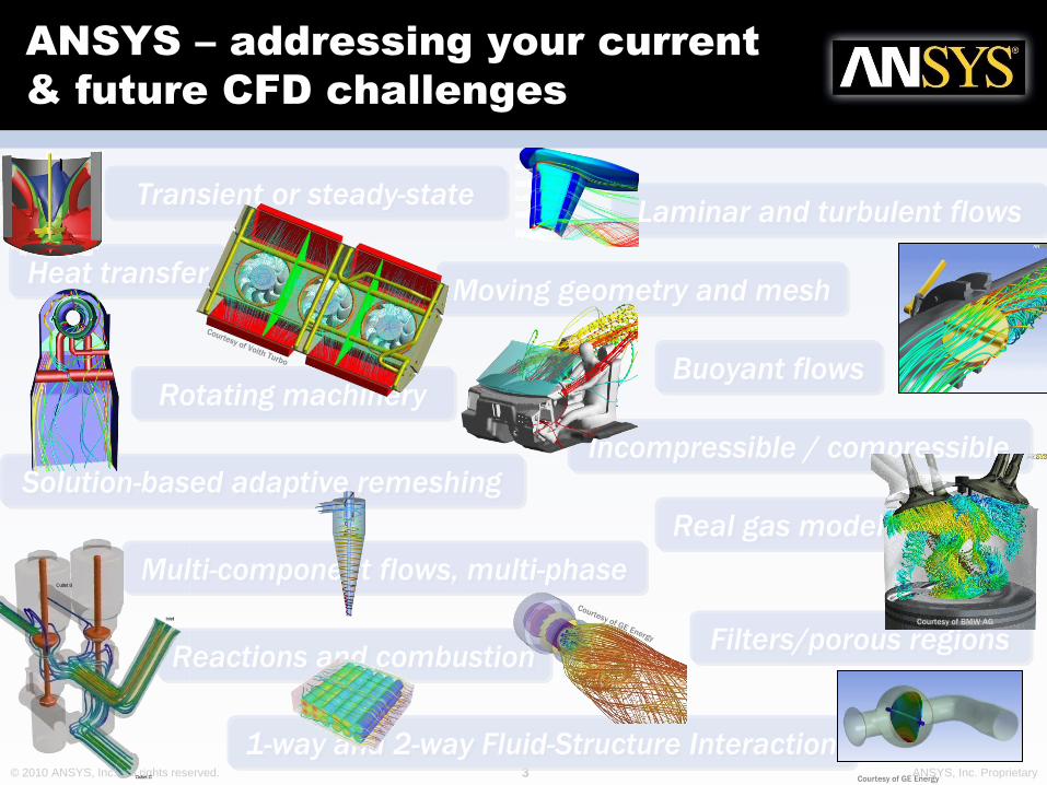
ANSYS – addressing your current
& future CFD challenges
Transient or steady-stateLaminar and turbulent flows
Heat transfer
Buoyant flows
Incompressible / compressible
Multi-component flows, multi-phase
Real gas modeling
Filters/porous regionsReactions and combustion
Moving geometry and mesh
Rotating machinery
Solution-based adaptive remeshing
1-way and 2-way Fluid-Structure InteractionCourtesy of GE Energy
Courtesy of BMW AG
© 2010 ANSYS, Inc. All rights reserved. 4 ANSYS, Inc. Proprietary
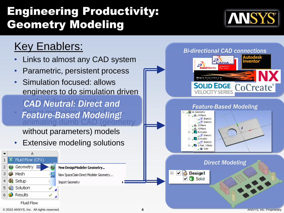
Key Enablers:• Links to almost any CAD system
• Parametric, persistent process
• Simulation focused: allows
engineers to do simulation driven
product development
• Direct modeling allows for re-
animating dumb CAD (geometry
without parameters) models
• Extensive modeling solutions
Engineering Productivity:
Geometry Modeling
Bi-directional CAD connections
Feature-Based Modeling
Direct Modeling
CAD Neutral: Direct and
Feature-Based Modeling!
© 2010 ANSYS, Inc. All rights reserved. 5 ANSYS, Inc. Proprietary
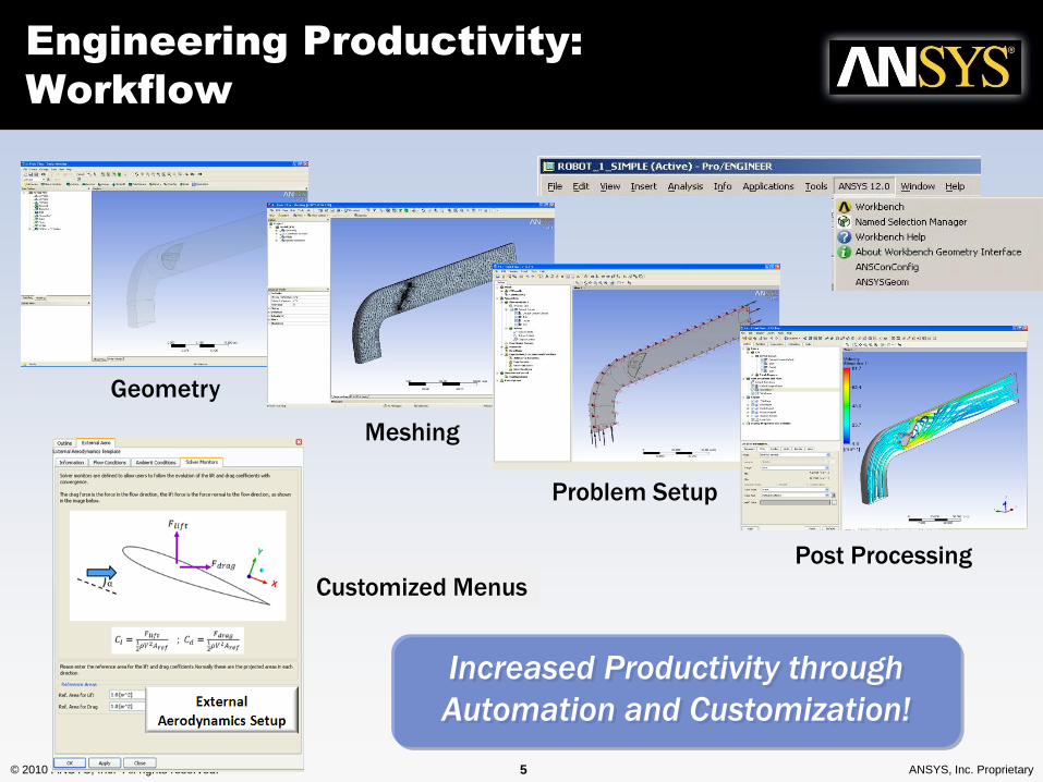
Setup Wizards
Engineering Productivity:
Workflow
Geometry
Meshing
Problem Setup
Post Processing
Customized Menus
Increased Productivity through
Automation and Customization!
© 2010 ANSYS, Inc. All rights reserved. 6 ANSYS, Inc. Proprietary
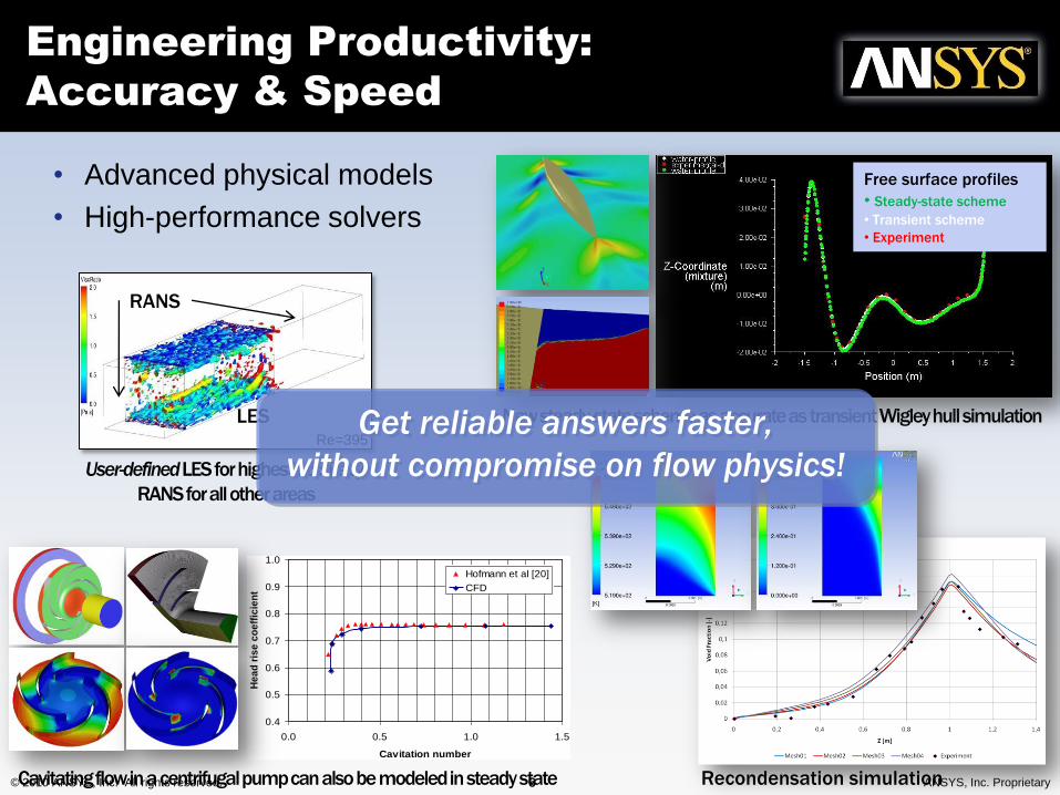
• Advanced physical models
• High-performance solvers
Engineering Productivity:
Accuracy & Speed
User-definedLES for highest accuracy;
RANS for all other areas
RANS
LESRe=395
New steady-state scheme as accurate as transient Wigley hull simulation
Free surface profiles
• Steady-state scheme
• Transient scheme
• Experiment
0.4
0.5
0.6
0.7
0.8
0.9
1.0
0.0 0.5 1.0 1.5
Cavitation number
He
ad
ris
e c
oe
ffic
ien
t
Hofmann et al [20]
CFD
Recondensation simulation Cavitating flow in a centrifugal pump can also be modeled in steady state
Get reliable answers faster,
without compromise on flow physics!
© 2010 ANSYS, Inc. All rights reserved. 7 ANSYS, Inc. Proprietary
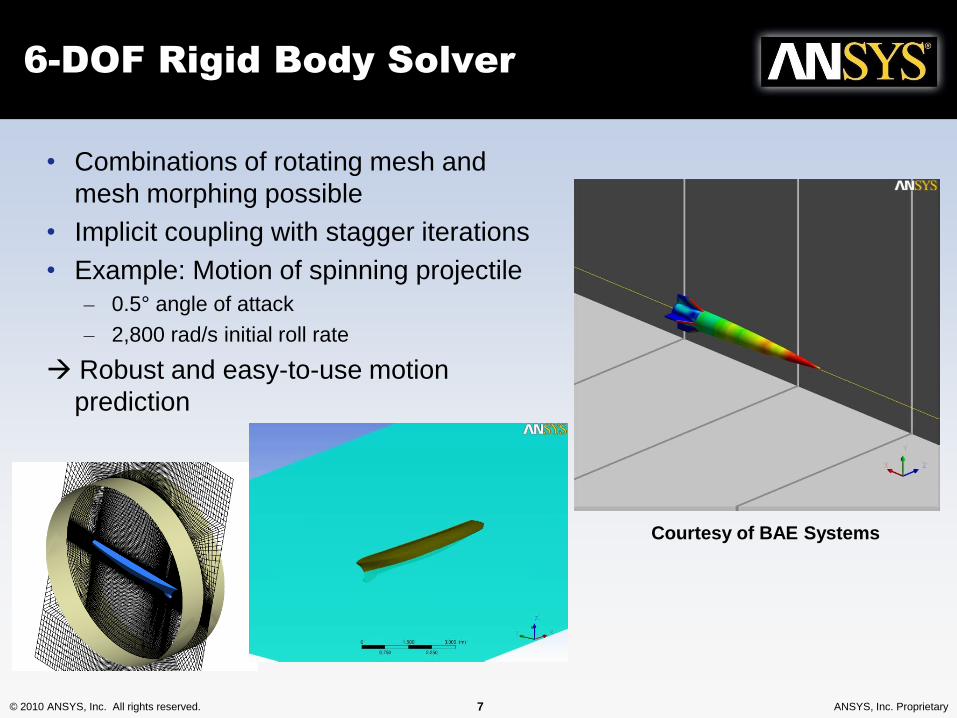
6-DOF Rigid Body Solver
• Combinations of rotating mesh and
mesh morphing possible
• Implicit coupling with stagger iterations
• Example: Motion of spinning projectile
– 0.5° angle of attack
– 2,800 rad/s initial roll rate
Robust and easy-to-use motion
prediction
Courtesy of BAE Systems
© 2010 ANSYS, Inc. All rights reserved. 8 ANSYS, Inc. Proprietary
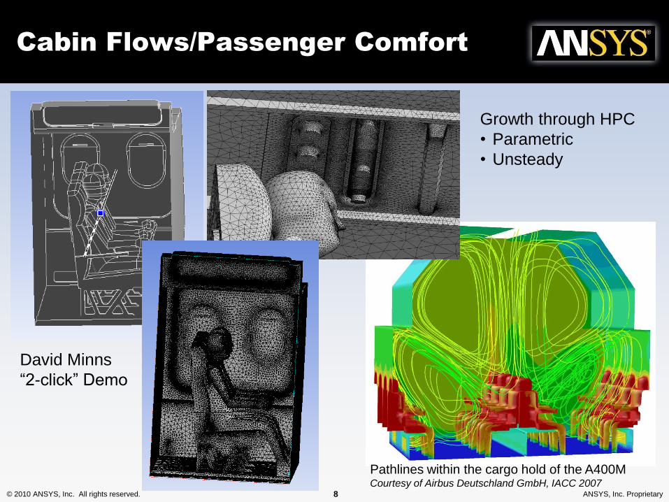
Cabin Flows/Passenger Comfort
David Minns
“2-click” Demo
Pathlines within the cargo hold of the A400M Courtesy of Airbus Deutschland GmbH, IACC 2007
Growth through HPC
• Parametric
• Unsteady
© 2010 ANSYS, Inc. All rights reserved. 9 ANSYS, Inc. Proprietary
0
5
10
15
20
25
30
35
40
45
50
0 2 4 6 8 10 12 14 16 18 20
Time (sec)
Halo
n C
on
ce
ntr
ati
on
(%
)
11-14-01 data
05-08-02 data
CFD-PROBE5
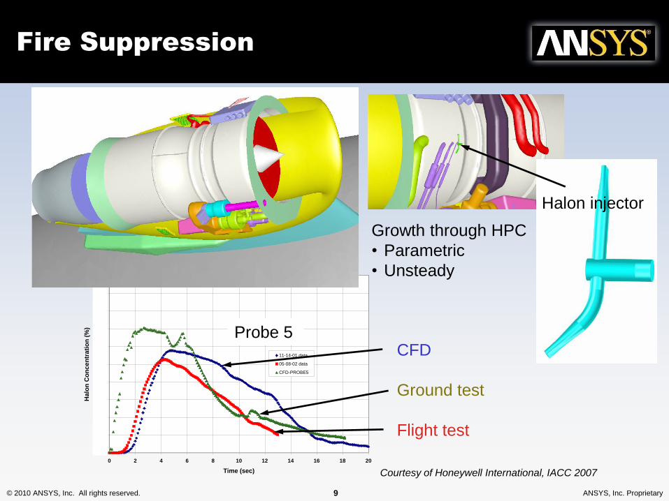
Fire Suppression
Probe 5CFD
Ground test
Flight test
Halon injector
Courtesy of Honeywell International, IACC 2007
Growth through HPC
• Parametric
• Unsteady
© 2010 ANSYS, Inc. All rights reserved. 10 ANSYS, Inc. Proprietary
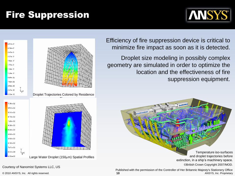
Courtesy of Nanomist Systems LLC, US
Droplet Trajectories Colored by Residence
Time
Large Water Droplet (150mm) Spatial Profiles
Efficiency of fire suppression device is critical to
minimize fire impact as soon as it is detected.
Droplet size modeling in possibly complex
geometry are simulated in order to optimize the
location and the effectiveness of fire
suppression equipment.
Temperature iso-surfaces
and droplet trajectories before
extinction, in a ship’s machinery space.
©British Crown Copyright 2007/MOD.
Published with the permission of the Controller of Her Britannic Majesty's Stationery Office
Fire Suppression
© 2010 ANSYS, Inc. All rights reserved. 11 ANSYS, Inc. Proprietary
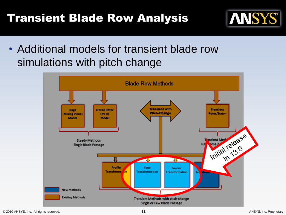
Transient Blade Row Analysis
• Additional models for transient blade row
simulations with pitch change
© 2010 ANSYS, Inc. All rights reserved. 12 ANSYS, Inc. Proprietary
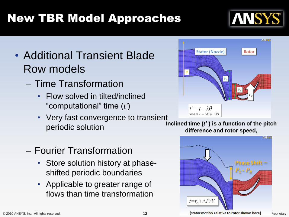
New TBR Model Approaches
• Additional Transient Blade
Row models
– Time Transformation
• Flow solved in tilted/inclined
“computational” time (t')
• Very fast convergence to transient
periodic solution
– Fourier Transformation
• Store solution history at phase-
shifted periodic boundaries
• Applicable to greater range of
flows than time transformation
Inclined time (t' ) is a function of the pitch
difference and rotor speed,
© 2010 ANSYS, Inc. All rights reserved. 13 ANSYS, Inc. Proprietary
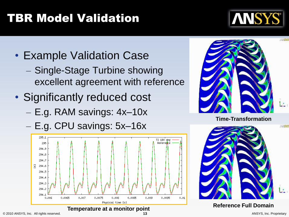
TBR Model Validation
• Example Validation Case
– Single-Stage Turbine showing
excellent agreement with reference
• Significantly reduced cost
– E.g. RAM savings: 4x–10x
– E.g. CPU savings: 5x–16xTime-Transformation
Reference Full DomainTemperature at a monitor point
© 2010 ANSYS, Inc. All rights reserved. 14 ANSYS, Inc. Proprietary
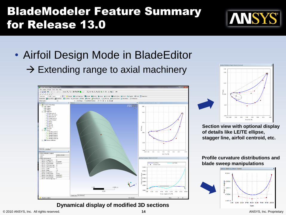
BladeModeler Feature Summary
for Release 13.0
• Airfoil Design Mode in BladeEditor
Extending range to axial machinery
Section view with optional display
of details like LE/TE ellipse,
stagger line, airfoil centroid, etc.
Dynamical display of modified 3D sections
Profile curvature distributions and
blade sweep manipulations
© 2010 ANSYS, Inc. All rights reserved. 15 ANSYS, Inc. Proprietary
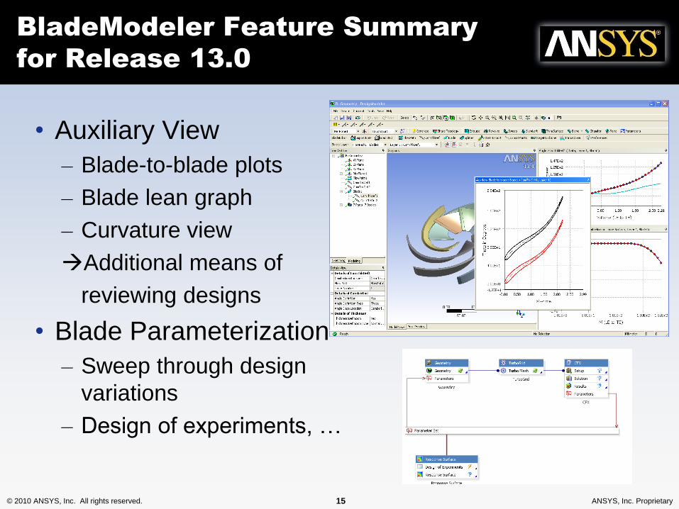
BladeModeler Feature Summary
for Release 13.0
• Auxiliary View
– Blade-to-blade plots
– Blade lean graph
– Curvature view
Additional means of
reviewing designs
• Blade Parameterization
– Sweep through design
variations
– Design of experiments, …
© 2010 ANSYS, Inc. All rights reserved. 16 ANSYS, Inc. Proprietary
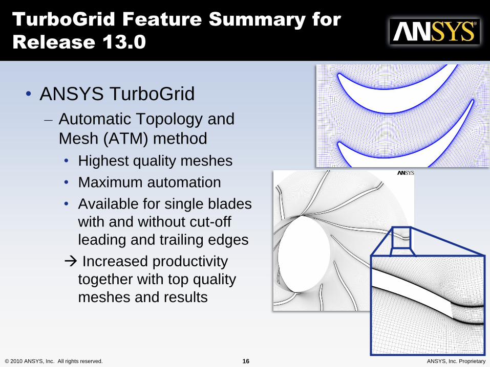
TurboGrid Feature Summary for
Release 13.0
• ANSYS TurboGrid
– Automatic Topology and
Mesh (ATM) method
• Highest quality meshes
• Maximum automation
• Available for single blades
with and without cut-off
leading and trailing edges
Increased productivity
together with top quality
meshes and results
© 2010 ANSYS, Inc. All rights reserved. 17 ANSYS, Inc. Proprietary
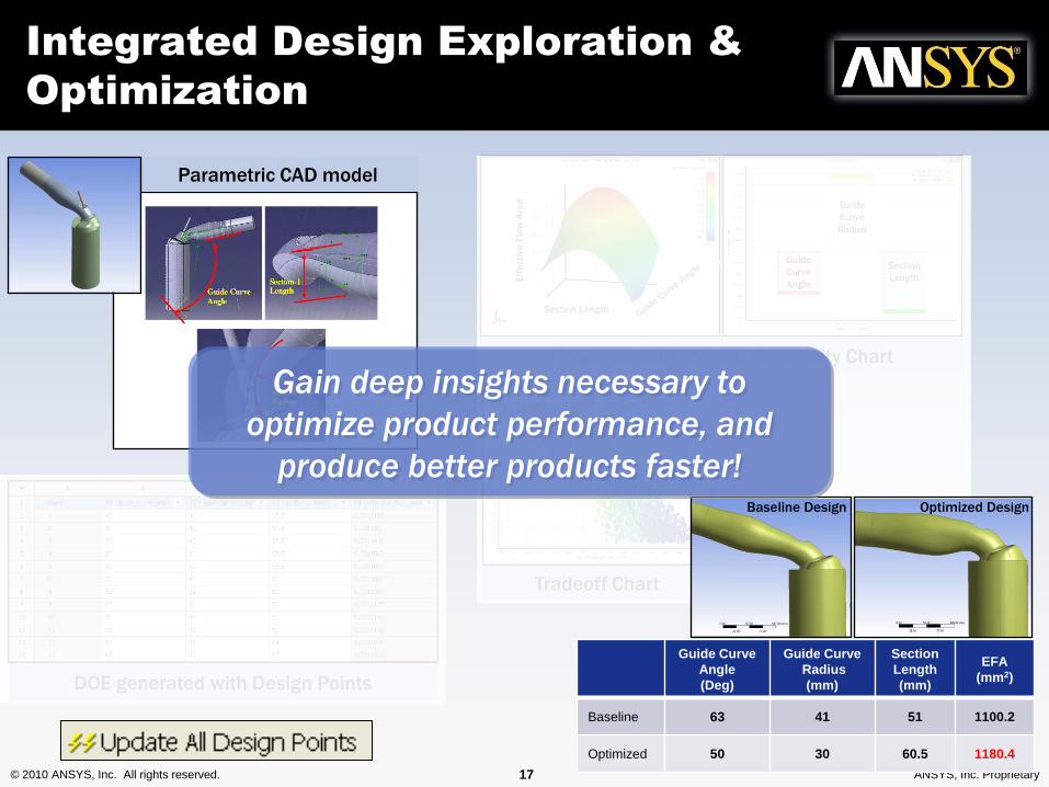
Integrated Design Exploration &
Optimization
Tradeoff Chart
Parametric CAD model
Response Surface and Sensitivity Chart
Section
Length
Guide
Curve
Angle
Guide
Curve
Radius
Eff
ecti
ve
Flo
w A
rea
Section Length
DOE generated with Design Points
Guide Curve
Angle
(Deg)
Guide Curve
Radius
(mm)
Section
Length
(mm)
EFA
(mm2)
Baseline 63 41 51 1100.2
Optimized 50 30 60.5 1180.4
Baseline Design Optimized Design
Gain deep insights necessary to
optimize product performance, and
produce better products faster!
© 2010 ANSYS, Inc. All rights reserved. 18 ANSYS, Inc. Proprietary
Drag sensitivity
Downforce sensitivity
Total pressure drop sensitivity
Total pressure drop sensitivity
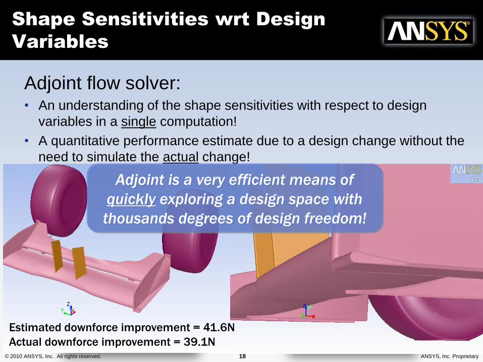
Estimated downforce improvement = 41.6N
Actual downforce improvement = 39.1N
Adjoint flow solver:• An understanding of the shape sensitivities with respect to design
variables in a single computation!
• A quantitative performance estimate due to a design change without the
need to simulate the actual change!
Adjoint is a very efficient means of
quickly exploring a design space with
thousands degrees of design freedom!
Shape Sensitivities wrt Design
Variables
© 2010 ANSYS, Inc. All rights reserved. 19 ANSYS, Inc. Proprietary
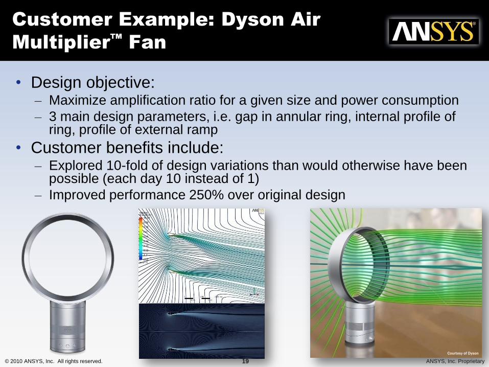
• Design objective:– Maximize amplification ratio for a given size and power consumption
– 3 main design parameters, i.e. gap in annular ring, internal profile of ring, profile of external ramp
• Customer benefits include:– Explored 10-fold of design variations than would otherwise have been
possible (each day 10 instead of 1)
– Improved performance 250% over original design
Customer Example: Dyson Air
Multiplier™
Fan
Courtesy of Dyson
© 2010 ANSYS, Inc. All rights reserved. 20 ANSYS, Inc. Proprietary
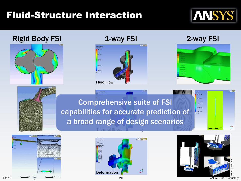
Fluid Flow
Thermal Stress
Fluid-Structure Interaction
Rigid Body FSI 1-way FSI 2-way FSI
Deformation
Co
urt
esy
of
Em
bra
co
Comprehensive suite of FSI
capabilities for accurate prediction of
a broad range of design scenarios
© 2010 ANSYS, Inc. All rights reserved. 21 ANSYS, Inc. Proprietary
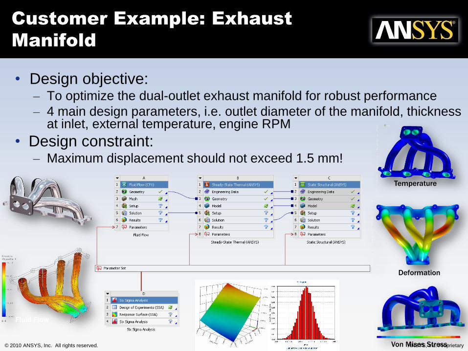
• Design objective:– To optimize the dual-outlet exhaust manifold for robust performance
– 4 main design parameters, i.e. outlet diameter of the manifold, thickness at inlet, external temperature, engine RPM
• Design constraint: – Maximum displacement should not exceed 1.5 mm!
Customer Example: Exhaust
Manifold
Fluid Flow
Deformation
Von Mises Stress
Temperature
© 2010 ANSYS, Inc. All rights reserved. 22 ANSYS, Inc. Proprietary
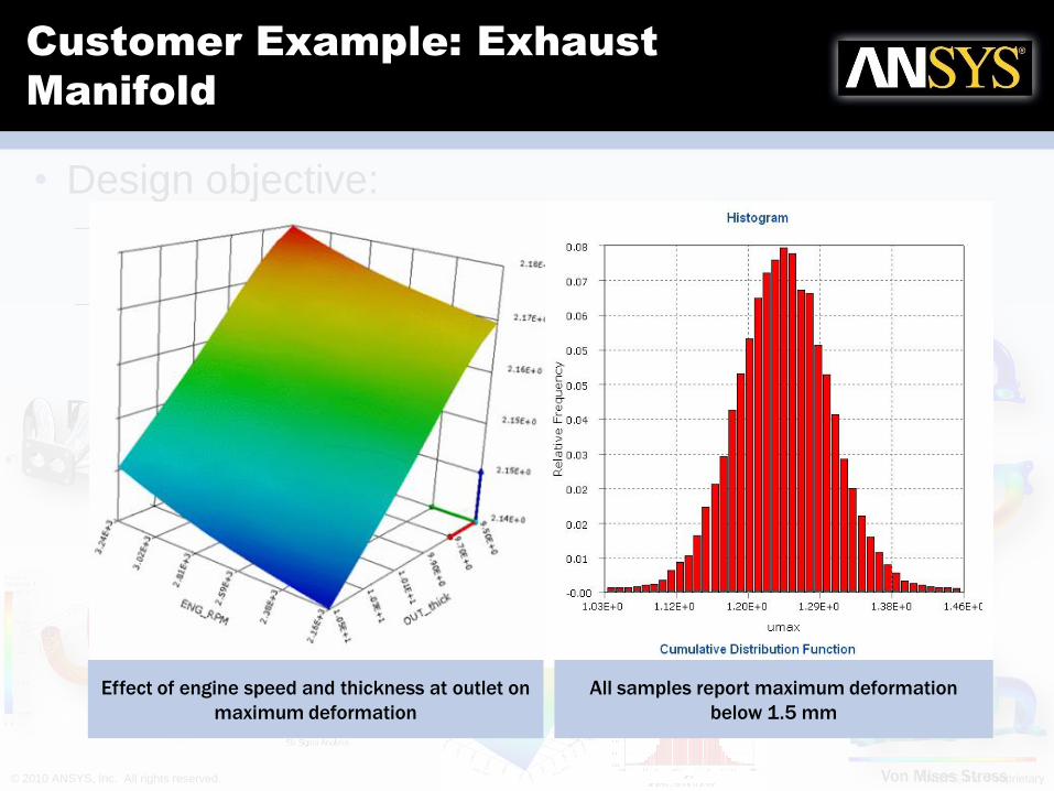
• Design objective:– To optimize the dual-outlet exhaust manifold for robust
performance
– 4 main design parameters, i.e. outlet diameter of the manifold, thickness at inlet, external temperature, engine RPM
• Design constraint: – Maximum displacement should not exceed 1.5 mm!
Customer Example: Exhaust
Manifold
Fluid Flow
Deformation
Von Mises Stress
Temperature
All samples report maximum deformation
below 1.5 mm
Effect of engine speed and thickness at outlet on
maximum deformation
© 2010 ANSYS, Inc. All rights reserved. 23 ANSYS, Inc. Proprietary
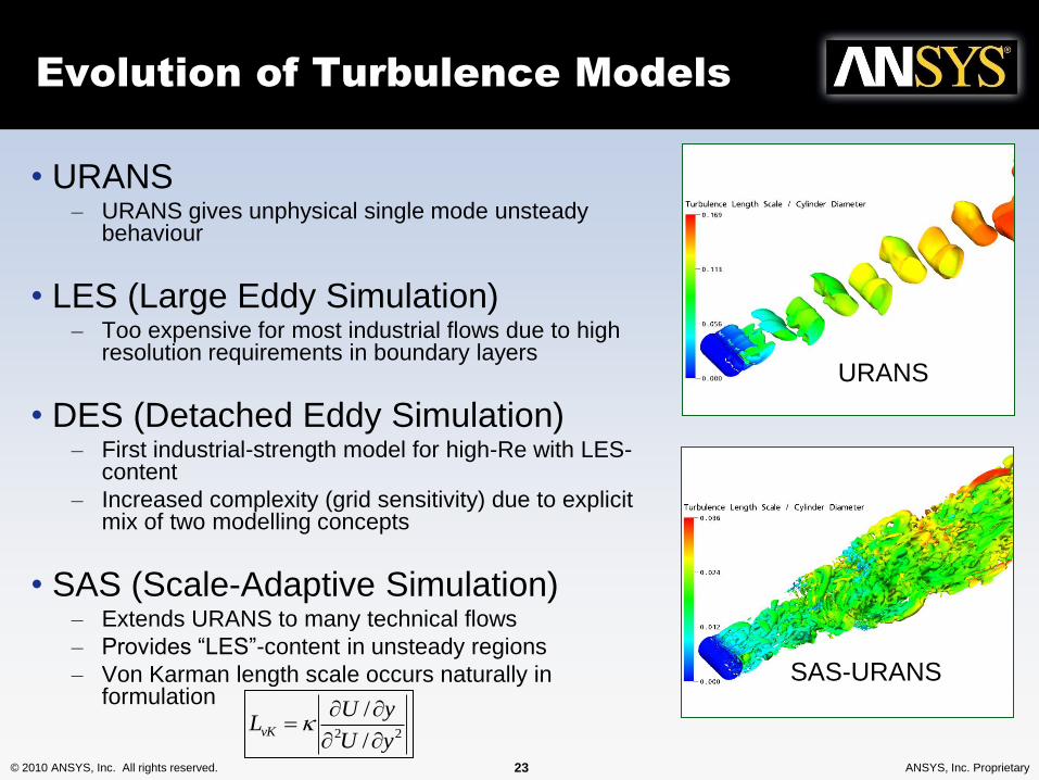
Evolution of Turbulence Models
• URANS– URANS gives unphysical single mode unsteady
behaviour
• LES (Large Eddy Simulation)– Too expensive for most industrial flows due to high
resolution requirements in boundary layers
• DES (Detached Eddy Simulation)– First industrial-strength model for high-Re with LES-
content
– Increased complexity (grid sensitivity) due to explicit mix of two modelling concepts
• SAS (Scale-Adaptive Simulation)– Extends URANS to many technical flows
– Provides “LES”-content in unsteady regions
– Von Karman length scale occurs naturally in formulation
URANS
SAS-URANS
22 /
/
yU
yULvK
© 2010 ANSYS, Inc. All rights reserved. 24 ANSYS, Inc. Proprietary
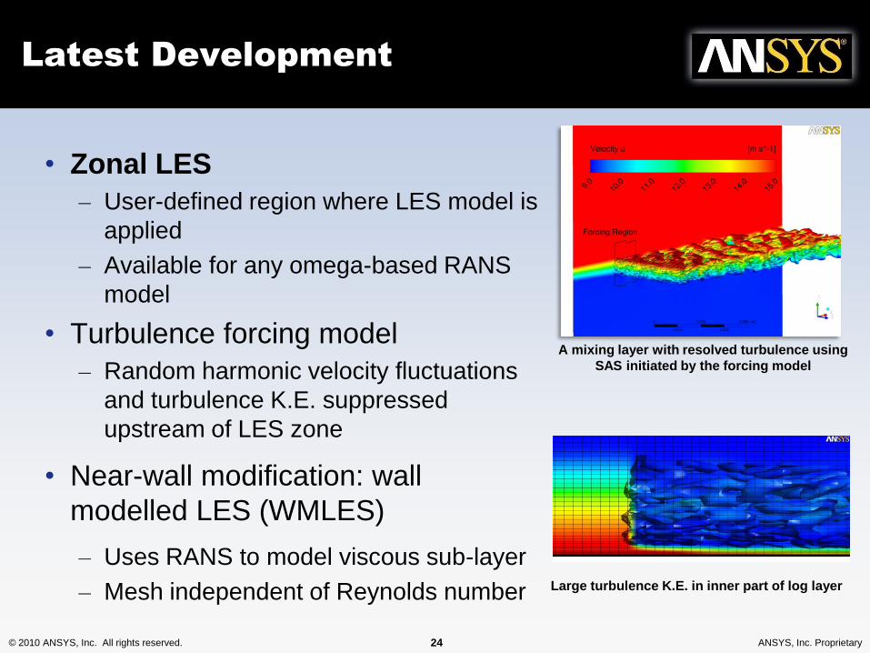
Latest Development
• Zonal LES
– User-defined region where LES model is
applied
– Available for any omega-based RANS
model
• Turbulence forcing model
– Random harmonic velocity fluctuations
and turbulence K.E. suppressed
upstream of LES zone
• Near-wall modification: wall
modelled LES (WMLES)
– Uses RANS to model viscous sub-layer
– Mesh independent of Reynolds number
A mixing layer with resolved turbulence using
SAS initiated by the forcing model
Large turbulence K.E. in inner part of log layer
© 2010 ANSYS, Inc. All rights reserved. 25 ANSYS, Inc. Proprietary
Courtesy of Oktal-SE
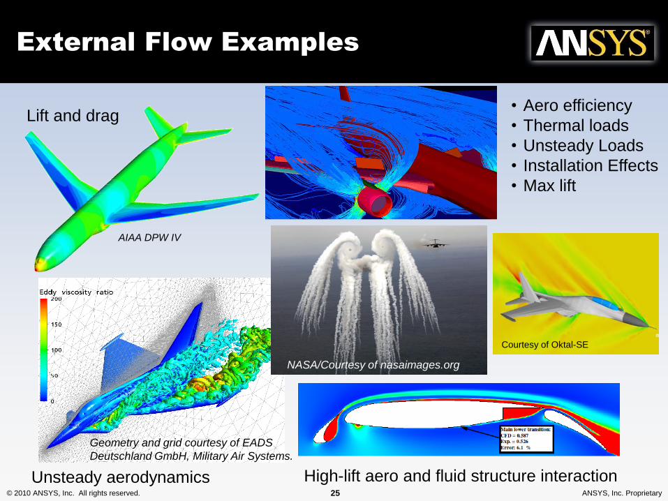
External Flow Examples
Lift and drag
AIAA DPW IV
Unsteady aerodynamics
Installation aero
High-lift aero and fluid structure interaction
• Aero efficiency
• Thermal loads
• Unsteady Loads
• Installation Effects
• Max lift
Geometry and grid courtesy of EADS
Deutschland GmbH, Military Air Systems.
NASA/Courtesy of nasaimages.org
© 2010 ANSYS, Inc. All rights reserved. 26 ANSYS, Inc. Proprietary
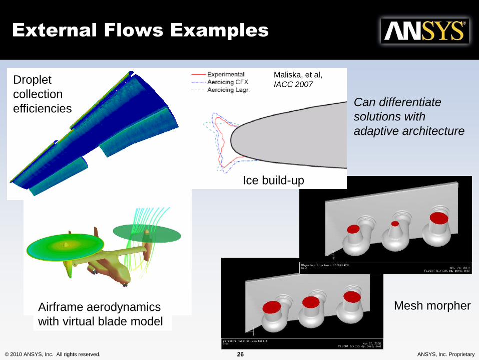
External Flows Examples
Airframe aerodynamics
with virtual blade model
Droplet
collection
efficiencies
Mesh morpher
Can differentiate
solutions with
adaptive architecture
Ice build-up
Maliska, et al,
IACC 2007
© 2010 ANSYS, Inc. All rights reserved. 27 ANSYS, Inc. Proprietary
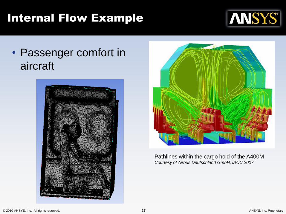
Internal Flow Example
• Passenger comfort in
aircraft
Pathlines within the cargo hold of the A400M Courtesy of Airbus Deutschland GmbH, IACC 2007
© 2010 ANSYS, Inc. All rights reserved. 28 ANSYS, Inc. Proprietary
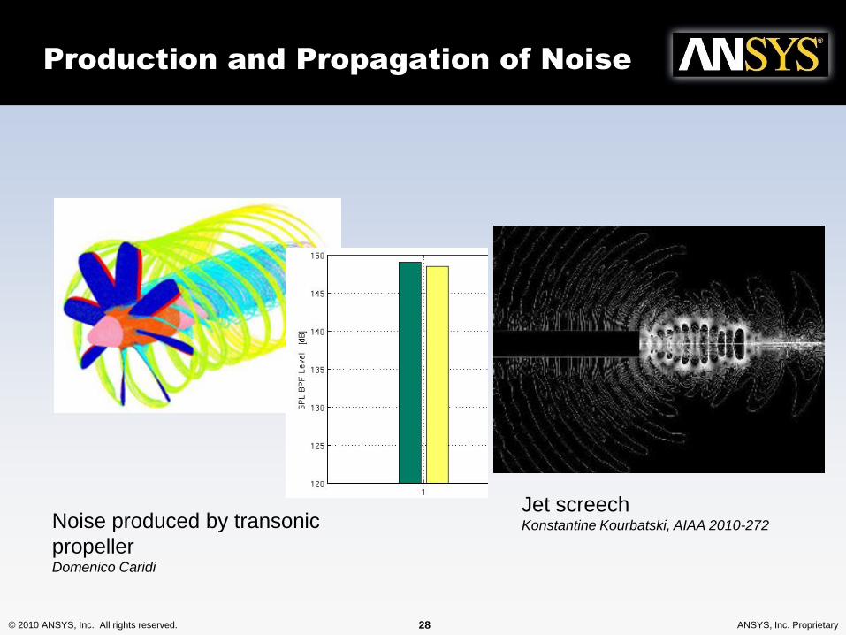
Production and Propagation of Noise
Noise produced by transonic
propellerDomenico Caridi
Jet screechKonstantine Kourbatski, AIAA 2010-272
© 2010 ANSYS, Inc. All rights reserved. 29 ANSYS, Inc. Proprietary
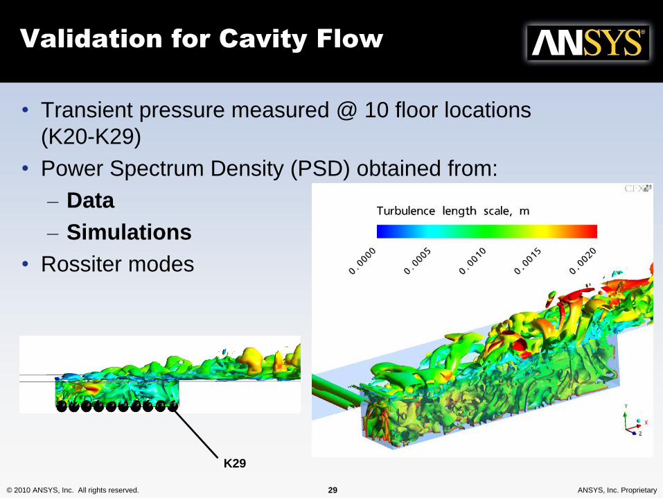
Validation for Cavity Flow
• Transient pressure measured @ 10 floor locations
(K20-K29)
• Power Spectrum Density (PSD) obtained from:
– Data
– Simulations
• Rossiter modes
K29
© 2010 ANSYS, Inc. All rights reserved. 30 ANSYS, Inc. Proprietary
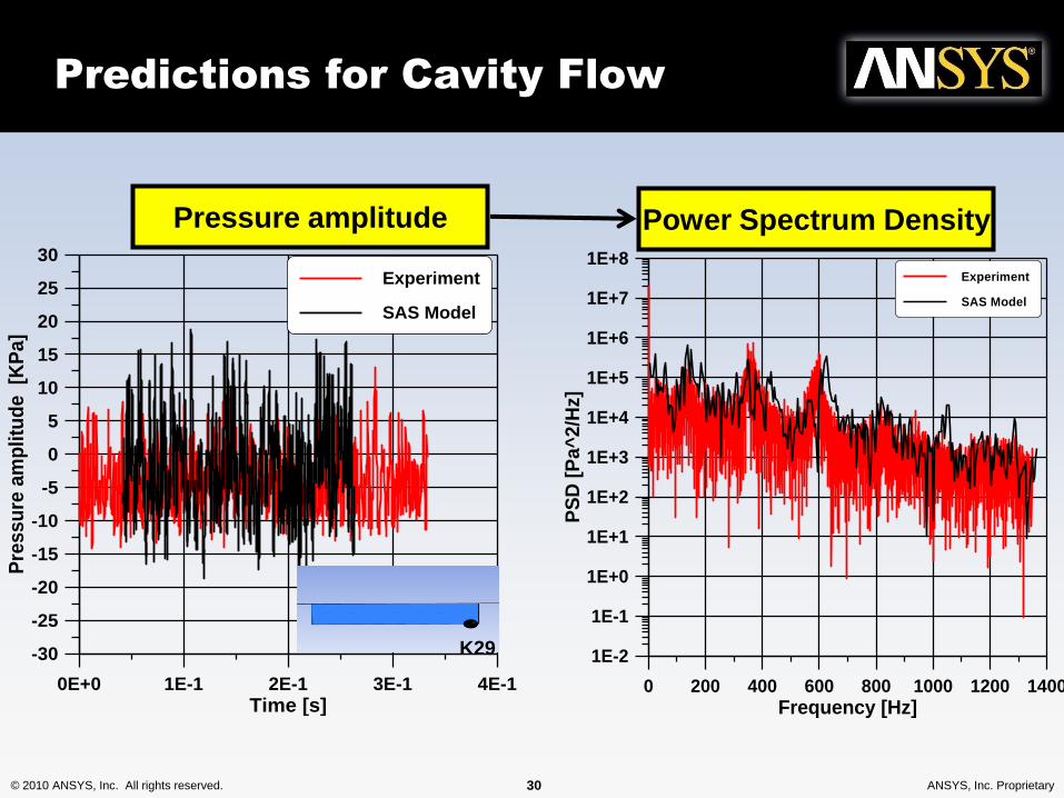
Predictions for Cavity Flow
0 200 400 600 800 1000 1200 1400
Frequency [Hz]
1E-2
1E-1
1E+0
1E+1
1E+2
1E+3
1E+4
1E+5
1E+6
1E+7
1E+8
PS
D [
Pa^
2/H
z]
Experiment
SAS Model
Pressure amplitude Power Spectrum Density
0E+0 1E-1 2E-1 3E-1 4E-1
Time [s]
-30
-25
-20
-15
-10
-5
0
5
10
15
20
25
30
Pre
ssu
re a
mp
litu
de
[K
Pa]
Experiment
SAS Model
K29
© 2010 ANSYS, Inc. All rights reserved. 31 ANSYS, Inc. Proprietary
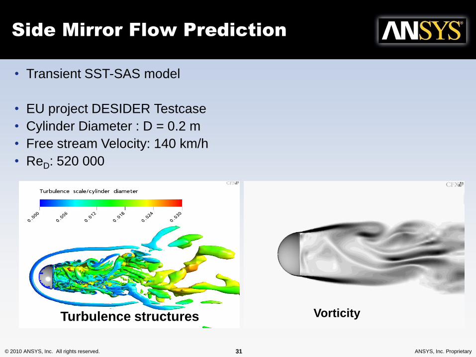
Side Mirror Flow Prediction
VorticityTurbulence structures
• Transient SST-SAS model
• EU project DESIDER Testcase
• Cylinder Diameter : D = 0.2 m
• Free stream Velocity: 140 km/h
• ReD: 520 000
© 2010 ANSYS, Inc. All rights reserved. 32 ANSYS, Inc. Proprietary
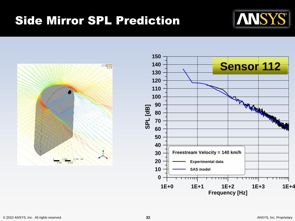
Side Mirror SPL Prediction
1E+0 1E+1 1E+2 1E+3 1E+4Frequency [Hz]
0
10
20
30
40
50
60
70
80
90
100
110
120
130
140
150
SP
L [
dB
]Freestream Velocity = 140 km/h
Experimental data
SAS model
Sensor 112
© 2010 ANSYS, Inc. All rights reserved. 33 ANSYS, Inc. Proprietary
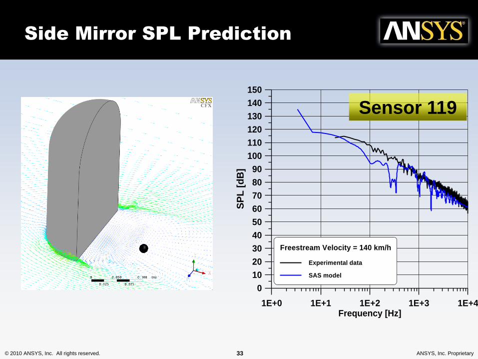
Side Mirror SPL Prediction
1E+0 1E+1 1E+2 1E+3 1E+4Frequency [Hz]
0
10
20
30
40
50
60
70
80
90
100
110
120
130
140
150
SP
L [
dB
]Freestream Velocity = 140 km/h
Experimental data
SAS model
Sensor 119
© 2010 ANSYS, Inc. All rights reserved. 34 ANSYS, Inc. Proprietary
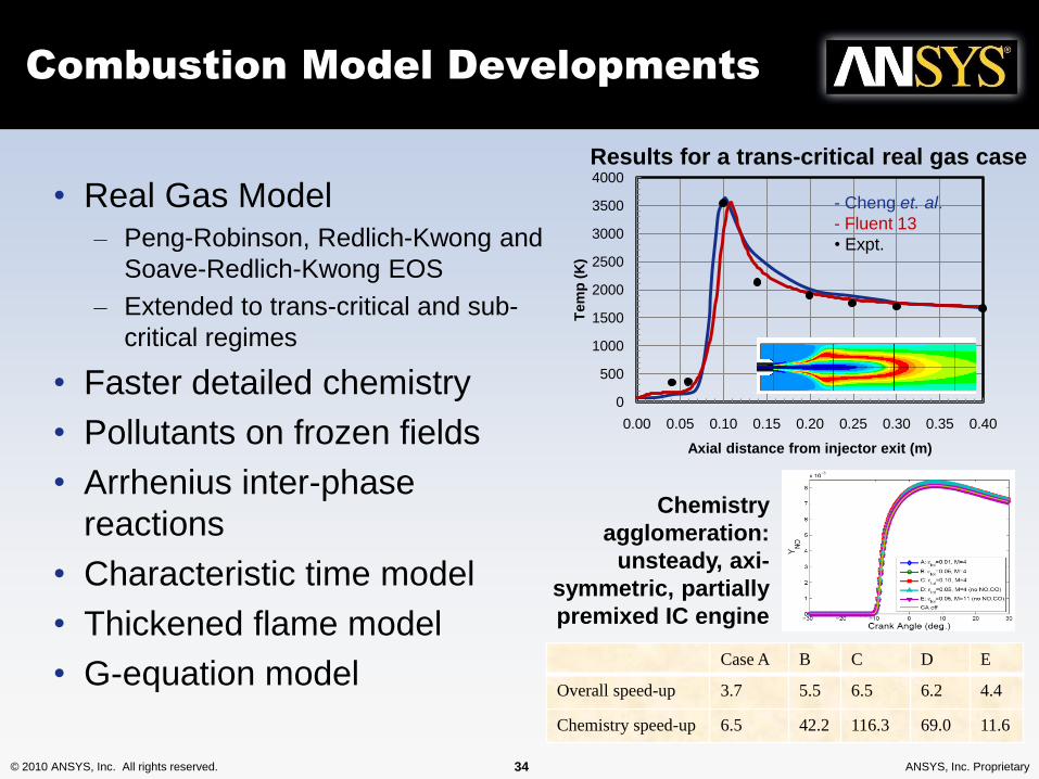
Combustion Model Developments
• Real Gas Model– Peng-Robinson, Redlich-Kwong and
Soave-Redlich-Kwong EOS
– Extended to trans-critical and sub-
critical regimes
• Faster detailed chemistry
• Pollutants on frozen fields
• Arrhenius inter-phase
reactions
• Characteristic time model
• Thickened flame model
• G-equation model
0
500
1000
1500
2000
2500
3000
3500
4000
0.00 0.05 0.10 0.15 0.20 0.25 0.30 0.35 0.40
Tem
p (
K)
Axial distance from injector exit (m)
- Cheng et. al.
- Fluent 13
• Expt.
Results for a trans-critical real gas case
Case A B C D E
Overall speed-up 3.7 5.5 6.5 6.2 4.4
Chemistry speed-up 6.5 42.2 116.3 69.0 11.6
Chemistry
agglomeration:
unsteady, axi-
symmetric, partially
premixed IC engine
© 2010 ANSYS, Inc. All rights reserved. 35 ANSYS, Inc. Proprietary
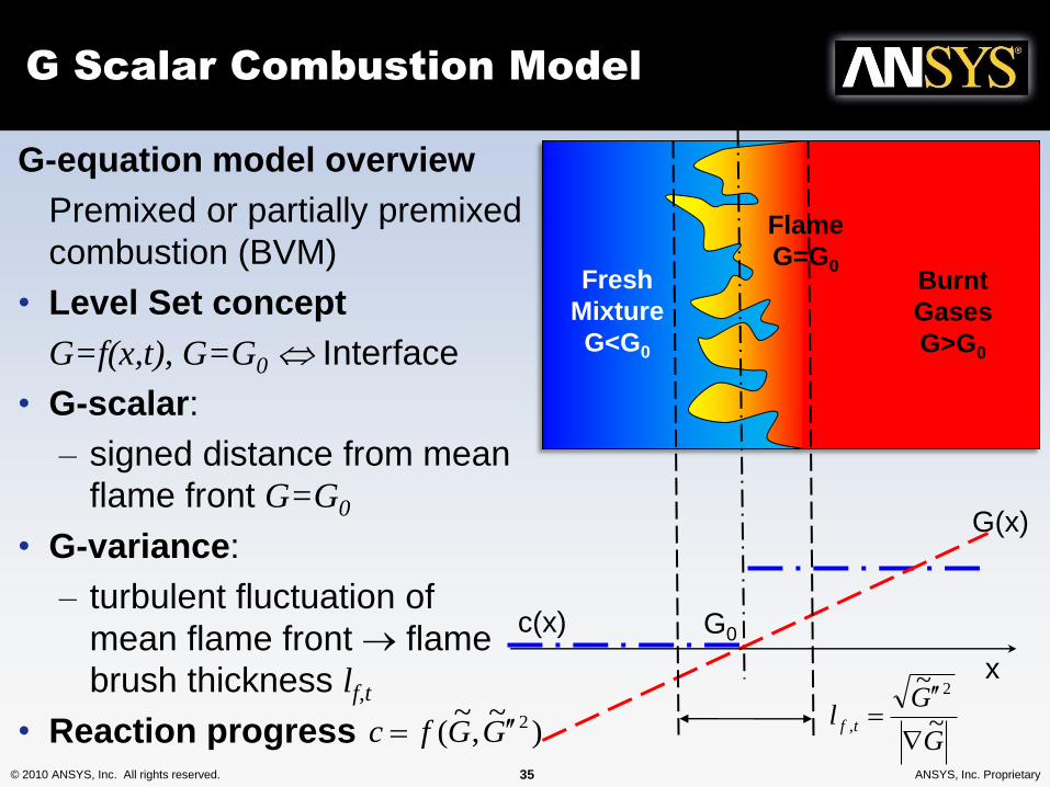
G Scalar Combustion Model
G-equation model overview
Premixed or partially premixed
combustion (BVM)
• Level Set concept
G=f(x,t), G=G0 Interface
• G-scalar:
– signed distance from mean
flame front G=G0
• G-variance:
– turbulent fluctuation of
mean flame front flame
brush thickness lf,t
• Reaction progress )~
,~
( 2GGfc
Fresh
Mixture
G<G0
Burnt
Gases
G>G0
Flame
G=G0
G(x)
x
c(x)
G
Gl tf ~
~ 2
,
G0
© 2010 ANSYS, Inc. All rights reserved. 36 ANSYS, Inc. Proprietary
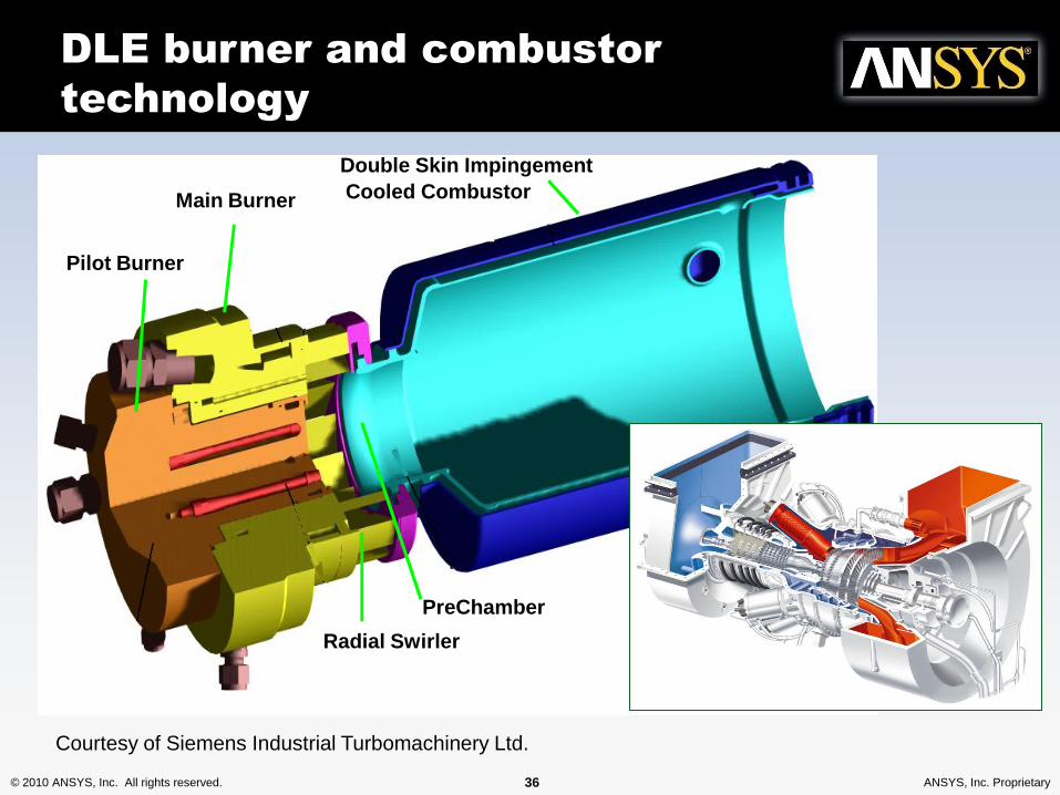
Double Skin Impingement
Cooled CombustorMain Burner
Pilot Burner
PreChamber
Radial Swirler
DLE burner and combustor
technology
Courtesy of Siemens Industrial Turbomachinery Ltd.
© 2010 ANSYS, Inc. All rights reserved. 37 ANSYS, Inc. Proprietary
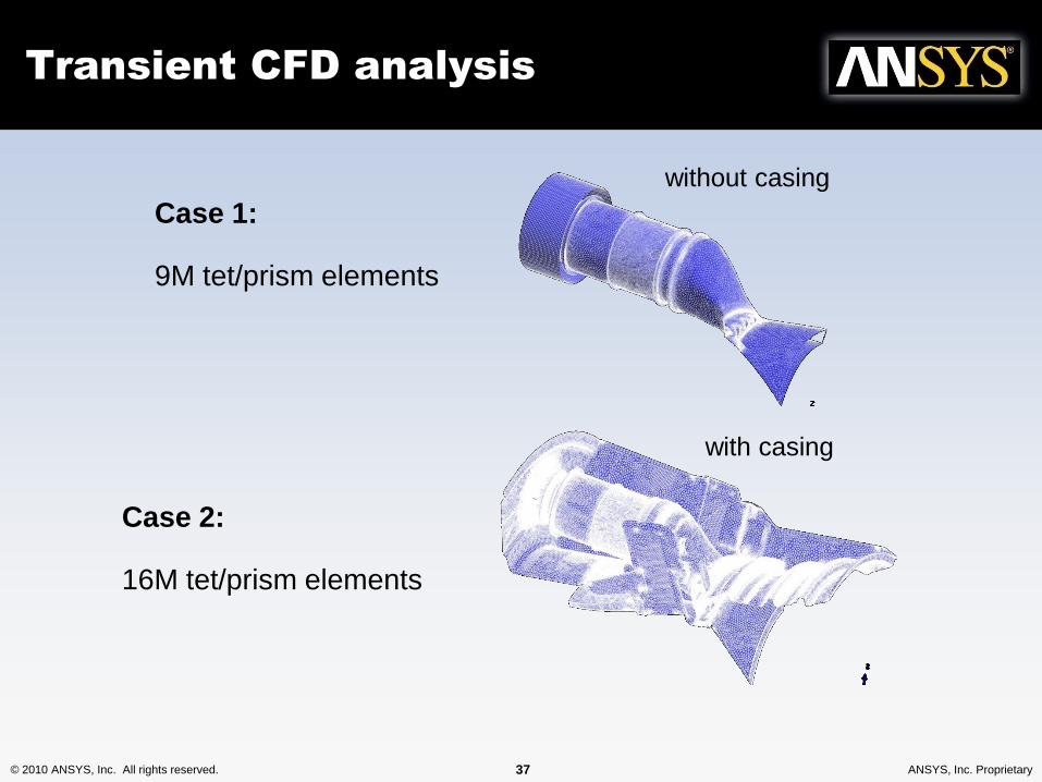
Transient CFD analysis
without casing
Case 1:
9M tet/prism elements
with casing
Case 2:
16M tet/prism elements
© 2010 ANSYS, Inc. All rights reserved. 38 ANSYS, Inc. Proprietary
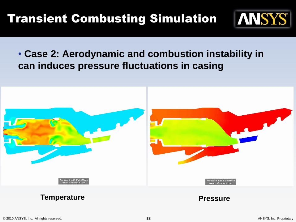
Transient Combusting Simulation
PressureTemperature
• Case 2: Aerodynamic and combustion instability in
can induces pressure fluctuations in casing
© 2010 ANSYS, Inc. All rights reserved. 39 ANSYS, Inc. Proprietary
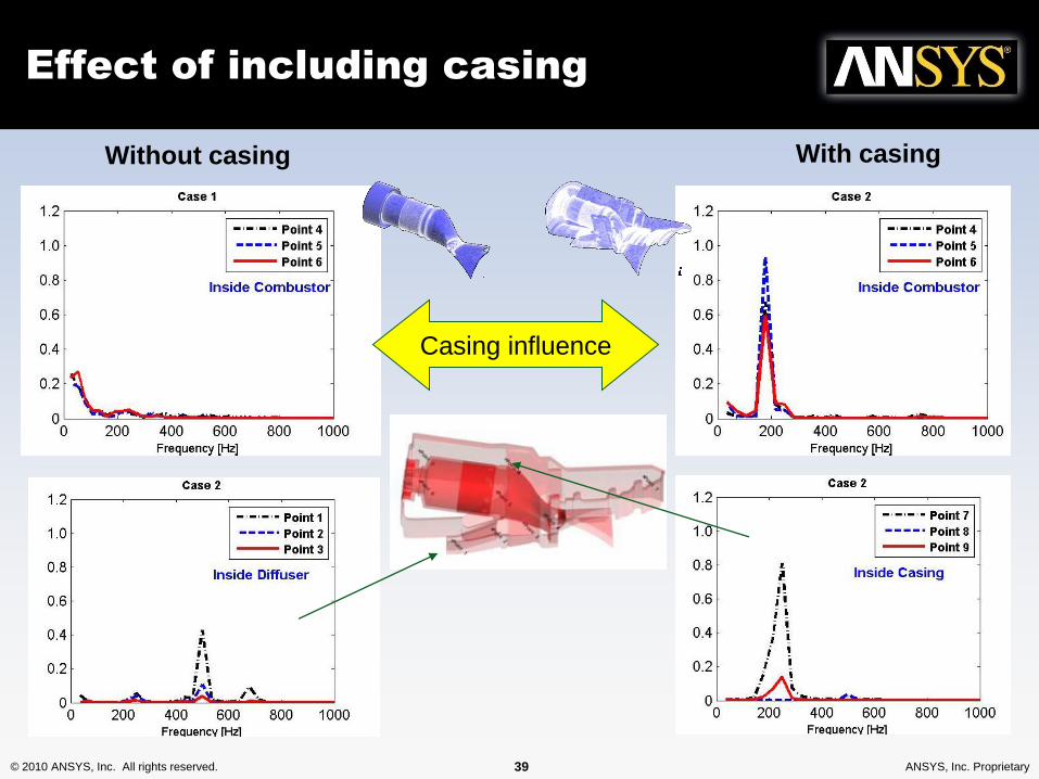
Effect of including casing
Casing influence
Without casing With casing
© 2010 ANSYS, Inc. All rights reserved. 40 ANSYS, Inc. Proprietary
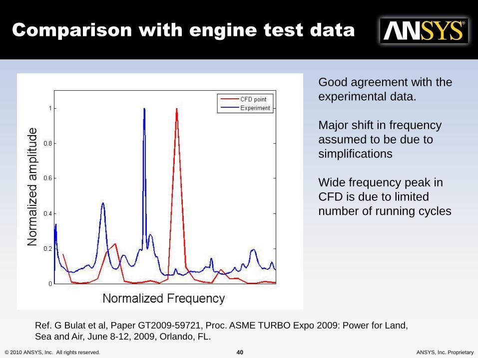
Comparison with engine test data
Good agreement with the
experimental data.
Major shift in frequency
assumed to be due to
simplifications
Wide frequency peak in
CFD is due to limited
number of running cycles
Ref. G Bulat et al, Paper GT2009-59721, Proc. ASME TURBO Expo 2009: Power for Land,
Sea and Air, June 8-12, 2009, Orlando, FL.
© 2010 ANSYS, Inc. All rights reserved. 41 ANSYS, Inc. Proprietary
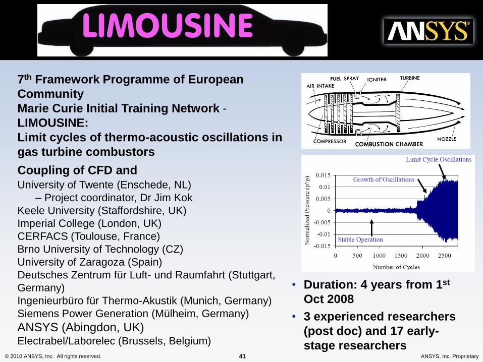
7th Framework Programme of European
Community
Marie Curie Initial Training Network -
LIMOUSINE:
Limit cycles of thermo-acoustic oscillations in
gas turbine combustors
Coupling of CFD and University of Twente (Enschede, NL)
– Project coordinator, Dr Jim Kok
Keele University (Staffordshire, UK)
Imperial College (London, UK)
CERFACS (Toulouse, France)
Brno University of Technology (CZ)
University of Zaragoza (Spain)
Deutsches Zentrum für Luft- und Raumfahrt (Stuttgart,
Germany)
Ingenieurbüro für Thermo-Akustik (Munich, Germany)
Siemens Power Generation (Mülheim, Germany)
ANSYS (Abingdon, UK)Electrabel/Laborelec (Brussels, Belgium)
• Duration: 4 years from 1st
Oct 2008
• 3 experienced researchers
(post doc) and 17 early-
stage researchers
© 2010 ANSYS, Inc. All rights reserved. 42 ANSYS, Inc. Proprietary
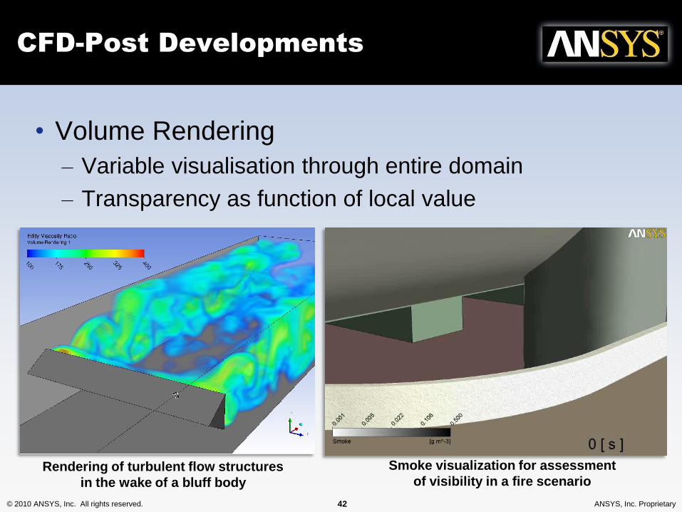
CFD-Post Developments
• Volume Rendering
– Variable visualisation through entire domain
– Transparency as function of local value
Smoke visualization for assessment
of visibility in a fire scenarioRendering of turbulent flow structures
in the wake of a bluff body
© 2010 ANSYS, Inc. All rights reserved. 43 ANSYS, Inc. Proprietary
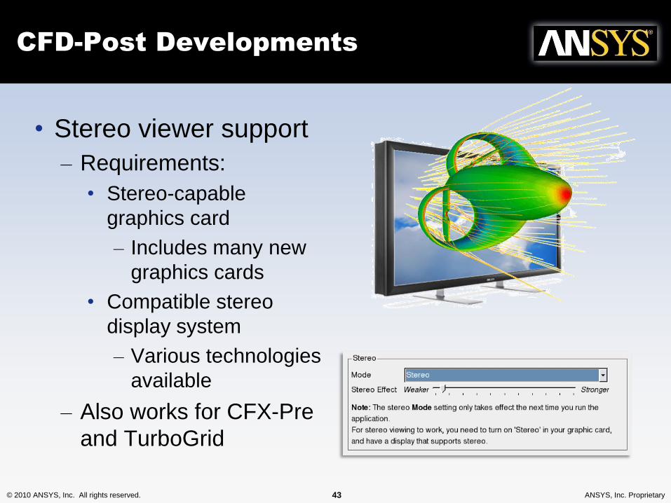
CFD-Post Developments
• Stereo viewer support
– Requirements:
• Stereo-capable
graphics card
– Includes many new
graphics cards
• Compatible stereo
display system
– Various technologies
available
– Also works for CFX-Pre
and TurboGrid
© 2010 ANSYS, Inc. All rights reserved. 44 ANSYS, Inc. Proprietary
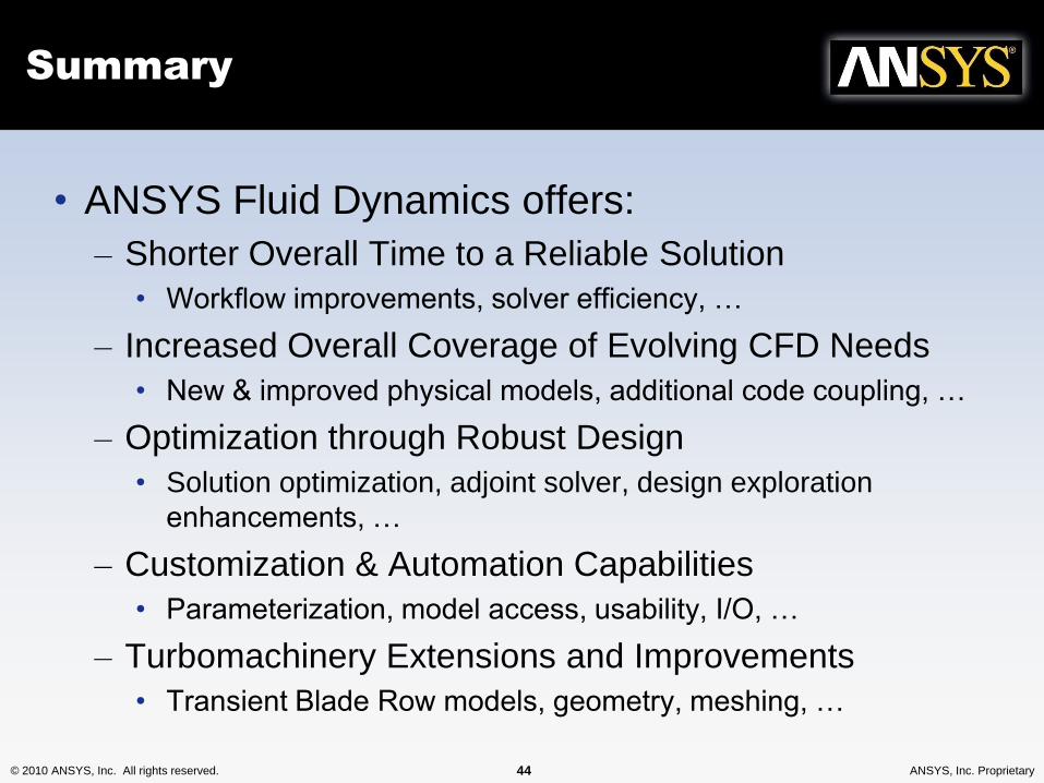
Summary
• ANSYS Fluid Dynamics offers:
– Shorter Overall Time to a Reliable Solution
• Workflow improvements, solver efficiency, …
– Increased Overall Coverage of Evolving CFD Needs
• New & improved physical models, additional code coupling, …
– Optimization through Robust Design
• Solution optimization, adjoint solver, design exploration
enhancements, …
– Customization & Automation Capabilities
• Parameterization, model access, usability, I/O, …
– Turbomachinery Extensions and Improvements
• Transient Blade Row models, geometry, meshing, …
© 2010 ANSYS, Inc. All rights reserved. 45 ANSYS, Inc. Proprietary© 2010 ANSYS, Inc. All rights reserved. 45 ANSYS, Inc. Proprietary
THANK YOU!