Embed Size (px)
Citation preview
1 Simulate to Innovate
Performance Investigation of an Aircraft Wing at Various Cant Angles of Winglets using CFD Simulation
Dinesh Myilsamy Post-Graduate Student
Pukyong National University, Dayeon Campus, Namgu,
Busan, Korea (South) 608-737
Yokesh Thirumalai Under-graduate Student Kumaraguru College of
Technology, Coimbatore, Tamil Nadu.
641- 049 [email protected]
Premkumar P.S Assistant Professor
Kumaraguru College of Technology,
Coimbatore, Tamil Nadu, 641- 049.
Abbreviations: Cl – Coefficient of Lift, Cd – Coefficient of drag,
α- Angle of attack
Keywords: Angle of Attack, Induced drag, Vortices, Normal wing (0° Winglet)
Abstract:
Winglet is a lift augmenting device which is attached at the wing tip of an aircraft. Winglets are used to improve the aerodynamic efficiency of an aircraft by lowering the formation of an Induced Drag which is caused by the wingtip vortices. Numerical studies have been carried out to investigate the best aerodynamic performance of a subsonic aircraft wing at various cant angles of winglets. This analytical study includes NACA 4412 airfoil coordinates for the wing design and the winglet with the blended design. The design process is carried out in CATIA-V5®. Flow features of the entire wing including winglet were examined at different cant angles of winglets varying from 0°, 30°& 90° degrees at different angles of attack from -2° to 10°. Discretization and the CFD simulation has been carried out through AcuSolve®, and the Post-processing results are obtained using AcuProbe® and AcuFieldview®. We have observed among the cases of this study, wings with winglets produces higher Cl/Cd ratio performance than the normal aircraft wing without winglets. Up to certain degree of angle of attack and by further increasing to higher angle of attack its performance getting diminished. The investigated concept of variable angle winglets appears to be a promising alternative for improving the aerodynamic efficiency of an aircraft.
Introduction
HE main purpose of any winglet is to improve the aircrafts aerodynamic performance by reducing the induced drag formation at the wing tips. [1]- [25]. The term winglet was previously used to describe an additional lifting surface on an aircraft. Wingtip devices are usually intended to improve the efficiency
of fixed-wing aircraft [1]. There are several types of wingtip devices, and although they function in different manners, the intended effect is always to reduce the aircraft's drag by partial recovery of the tip vortex energy. Wingtip devices can also improve aircraft handling characteristics and enhance safety. Such devices increase the effective aspect ratio of a wing without materially increasing the wingspan. Note that an extension of span would lower lift-induced drag, but would increase parasitic drag and would require boosting the strength and weight of the wing.
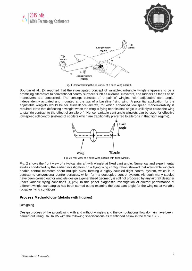
It is well known that any sort of body exposed in a viscous flow experiences profile drag, whether it produces lift or not. The induced drag is a different type of drag. It is caused by the pressure imbalance at the tip of a finite wing between its upper (pressure side) and lower (suction side) surfaces. That imbalance is necessary in order to produce a positive lift force. However, near the tip the high pressure air from the lower side tends to move upwards, where the pressure is lower, causing the streamlines to curl (see Fig. 1). This three-dimensional motion leads to the formation of a vortex, which alters the flow field and induces a velocity component in the downward direction at the wing, called downwash [2-4]. The induced flow pattern causes the relative velocity to cant downwards at each airfoil section of the wing, thus reducing the apparent angle of attack. The lift vector is tilted backwards and a force component in the direction of the drag appears, called induced drag. Reducing the size of this tip vortex and minimizing the induced drag is of great importance for the modern aircraft designers. For this purpose designers developed the winglet concept. Winglets are specially designed extensions adjusted to the wingtip that alter the velocity and pressure field and reduce the induced drag term, thus increasing aerodynamic efficiency.
T
2 Simulate to Innovate
Fig. 1 Demonstrating the tip vortex of a fixed wing aircraft.
Bourdin et al., [5] reported that the investigated concept of variable-cant-angle winglets appears to be a promising alternative to conventional control surfaces such as ailerons, elevators, and rudders as far as basic maneuvers are concerned. The concept consists of a pair of winglets with adjustable cant angle, independently actuated and mounted at the tips of a baseline flying wing. A potential application for the adjustable winglets would be for surveillance aircraft, for which enhanced low-speed maneuverability is required. Note that deflecting a winglet when the wing is flying near its stall angle is unlikely to cause the wing to stall (in contrast to the effect of an aileron). Hence, variable cant-angle winglets can be used for effective low-speed roll control (instead of spoilers which are traditionally preferred to ailerons in that flight regime).
Fig. 2 Front view of a fixed wing aircraft with fixed winglet.
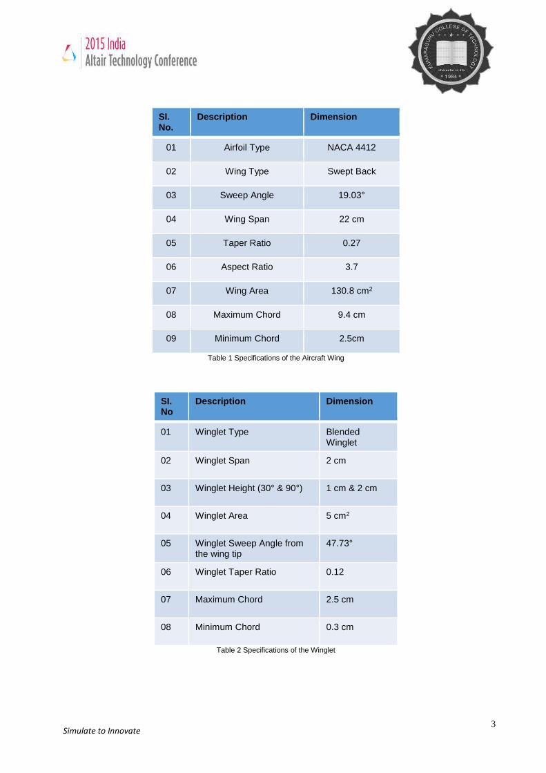
Fig. 2 shows the front view of a typical aircraft with winglet at fixed cant angle. Numerical and experimental studies conducted by the earlier investigators on a flying wing configuration showed that adjustable winglets enable control moments about multiple axes, forming a highly coupled flight control system, which is in contrast to conventional control surfaces, which form a decoupled control system. Although many studies have been carried out for winglets design a generalized geometry is still not proposed by any aircraft designer under variable flying conditions [1]-[25]. In this paper diagnostic investigation of aircraft performance at different winglet cant angles has been carried out to examine the best cant angle for the winglets at variable lucrative flying conditions. Process Methodology (details with figures) Designing Design process of the aircraft wing with and without winglets and the computational flow domain have been carried out using CATIA V5 with the following specifications as mentioned below in the table 1 & 2.
3 Simulate to Innovate
SI. No.
Description Dimension
01 Airfoil Type NACA 4412
02 Wing Type Swept Back
03 Sweep Angle 19.03°
04 Wing Span 22 cm
05 Taper Ratio 0.27
06 Aspect Ratio 3.7
07 Wing Area 130.8 cm2
08 Maximum Chord 9.4 cm
09 Minimum Chord 2.5cm
Table 1 Specifications of the Aircraft Wing
SI. No
Description Dimension
01 Winglet Type Blended Winglet
02 Winglet Span 2 cm
03 Winglet Height (30° & 90°) 1 cm & 2 cm
04 Winglet Area 5 cm2
05 Winglet Sweep Angle from the wing tip
47.73°
06 Winglet Taper Ratio 0.12
07 Maximum Chord 2.5 cm
08 Minimum Chord 0.3 cm
Table 2 Specifications of the Winglet
4 Simulate to Innovate
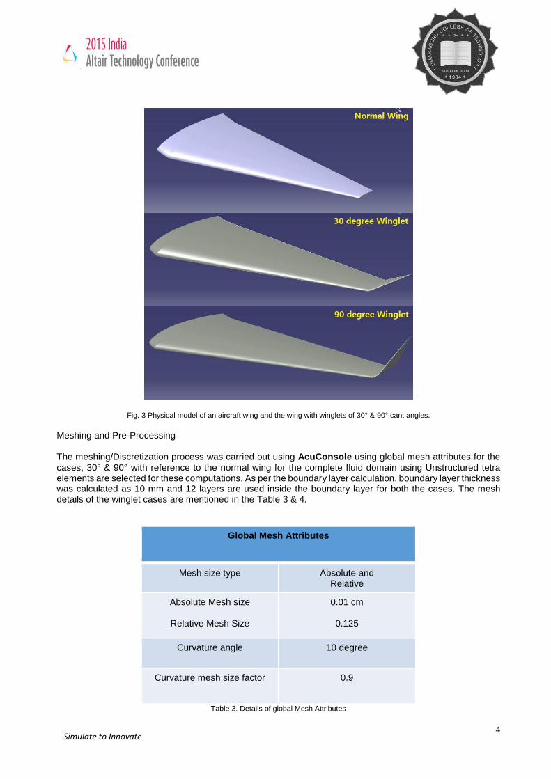
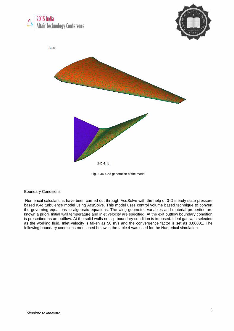
Fig. 3 Physical model of an aircraft wing and the wing with winglets of 30° & 90° cant angles. Meshing and Pre-Processing The meshing/Discretization process was carried out using AcuConsole using global mesh attributes for the cases, 30° & 90° with reference to the normal wing for the complete fluid domain using Unstructured tetra elements are selected for these computations. As per the boundary layer calculation, boundary layer thickness was calculated as 10 mm and 12 layers are used inside the boundary layer for both the cases. The mesh details of the winglet cases are mentioned in the Table 3 & 4.
Global Mesh Attributes
Mesh size type Absolute and Relative
Absolute Mesh size
Relative Mesh Size
0.01 cm
0.125
Curvature angle 10 degree
Curvature mesh size factor 0.9
Table 3. Details of global Mesh Attributes
5 Simulate to Innovate
Table 4. Mesh Details
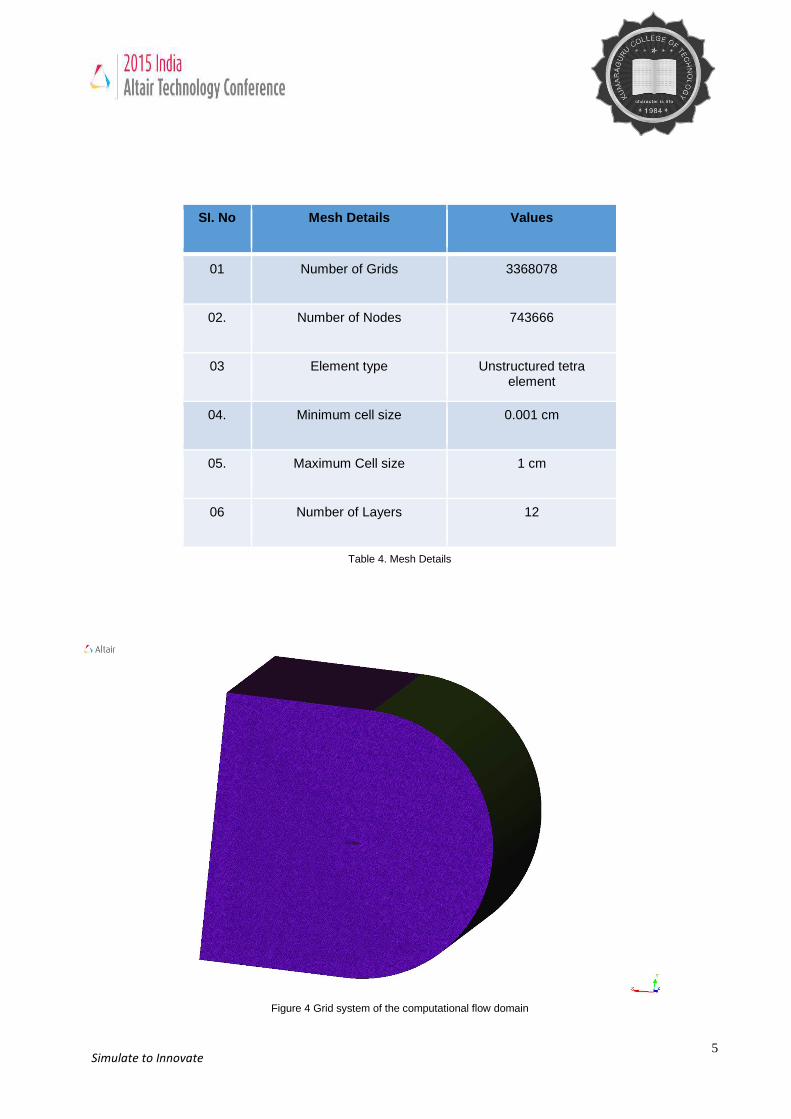
Figure 4 Grid system of the computational flow domain
SI. No Mesh Details Values
01 Number of Grids 3368078
02. Number of Nodes 743666
03 Element type Unstructured tetra element
04. Minimum cell size 0.001 cm
05. Maximum Cell size 1 cm
06 Number of Layers 12
6 Simulate to Innovate
Fig. 5 3D-Grid generation of the model
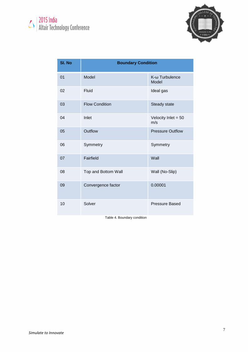
Boundary Conditions Numerical calculations have been carried out through AcuSolve with the help of 3-D steady state pressure based K-ω turbulence model using AcuSolve. This model uses control volume based technique to convert the governing equations to algebraic equations. The wing geometric variables and material properties are known a priori. Initial wall temperature and inlet velocity are specified. At the exit outflow boundary condition is prescribed as an outflow. At the solid walls no slip boundary condition is imposed. Ideal gas was selected as the working fluid. Inlet velocity is taken as 50 m/s and the convergence factor is set as 0.00001. The following boundary conditions mentioned below in the table 4 was used for the Numerical simulation.
7 Simulate to Innovate
SI. No Boundary Condition
01 Model K-ω Turbulence Model
02 Fluid Ideal gas
03 Flow Condition Steady state
04 Inlet Velocity Inlet = 50 m/s
05 Outflow Pressure Outflow
06 Symmetry Symmetry
07 Fairfield Wall
08 Top and Bottom Wall Wall (No-Slip)
09 Convergence factor 0.00001
10 Solver Pressure Based
Table 4. Boundary condition
8 Simulate to Innovate
Results & Discussions
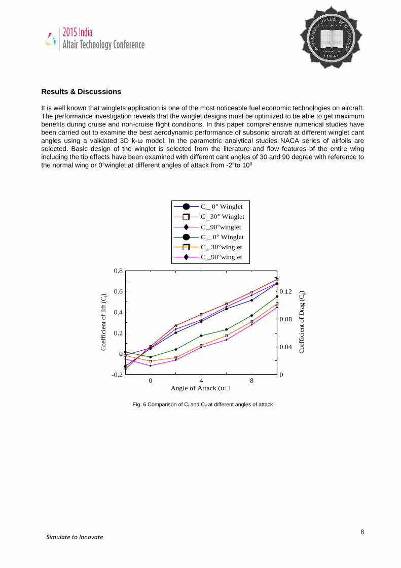
It is well known that winglets application is one of the most noticeable fuel economic technologies on aircraft. The performance investigation reveals that the winglet designs must be optimized to be able to get maximum benefits during cruise and non-cruise flight conditions. In this paper comprehensive numerical studies have been carried out to examine the best aerodynamic performance of subsonic aircraft at different winglet cant angles using a validated 3D k-ω model. In the parametric analytical studies NACA series of airfoils are selected. Basic design of the winglet is selected from the literature and flow features of the entire wing including the tip effects have been examined with different cant angles of 30 and 90 degree with reference to the normal wing or 0°winglet at different angles of attack from -2°to 100
0 4 8Angle of Attack (α)
-0.2
0
0.2
0.4
0.6
0.8
Coe
ffic
ient
of
lift
(C
l)
Cl_ 0° Winglet
Cl_30° Winglet
Cl_90°winglet
Cd_ 0° Winglet
Cd_30°winglet
Cd_90°winglet
0
0.04
0.08
0.12
Coe
ffic
ient
of
Dra
g (C
d)
Fig. 6 Comparison of Cl and Cd at different angles of attack
9 Simulate to Innovate
0 4 8Angle of Attack (α)
-4
0
4
8
12
Coe
ffic
ient
of
lift
to d
rag
rati
o (C
l/Cd)
Cl/Cd _90° Winglet
Cl/Cd_0° Winglet
Cl/Cd_30° Winglet
Cl/Cd Vs. Angle of attack for 0°, 30°, 90° Winglets
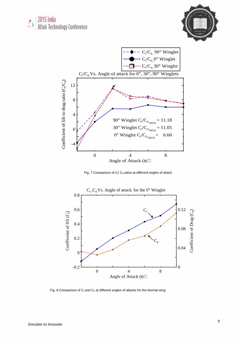
90° Winglet Cl/Cd MAX = 11.18
30° Winglet Cl/Cd MAX = 11.05
0° Winglet Cl/Cd MAX = 6.60
Fig. 8 Comparison of Cl and Cd at different angles of attacks for the Normal wing
Fig. 7 Comparison of Cl/ Cd ratios at different angles of attack
0 4 8Angle of Attack (α)
-0.2
0
0.2
0.4
0.6
0.8
Coe
ffic
eint
of
lift
(C
l)
0
0.04
0.08
0.12
Coe
ffic
ient
of
Dra
g (C
d)
Cd
Cl
Cl ,Cd Vs. Angle of attack for the 0° Winglet
10 Simulate to Innovate
0 4 8Angle of Attack (α)
-0.2
0
0.2
0.4
0.6
0.8C
oeff
icei
nt o
f li
ft (
Cl)
0
0.04
0.08
0.12
Coe
ffic
ient
of
Dra
g (C
d)
Cd
Cl
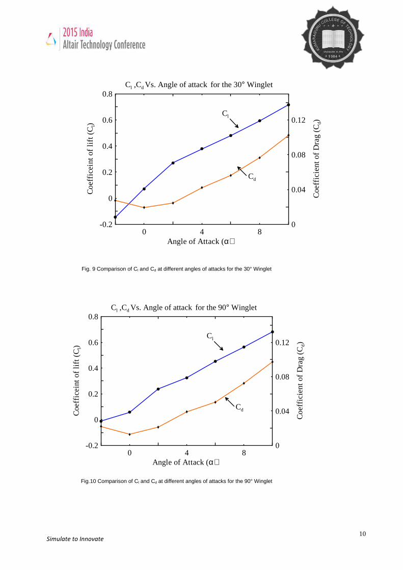
Cl ,Cd Vs. Angle of attack for the 30° Winglet
Fig. 9 Comparison of Cl and Cd at different angles of attacks for the 30° Winglet
Fig.10 Comparison of Cl and Cd at different angles of attacks for the 90° Winglet
0 4 8Angle of Attack (α)
-0.2
0
0.2
0.4
0.6
0.8
Coe
ffic
eint
of
lift
(C
l)
0
0.04
0.08
0.12
Coe
ffic
ient
of
Dra
g (C
d)
Cd
Cl
Cl ,Cd Vs. Angle of attack for the 90° Winglet
11 Simulate to Innovate
Fig. 6 shows the comparison of lift coefficient (Cl) and drag coefficient (Cd) at different angles of attack without and with winglet orienting at two different cant angles viz., 300 and 900. It is evident from Fig. 6 that a case with cant angle 900 is giving the highest coefficient of lift at various angles of attack (-2°- +10°). Nevertheless, as evident in Fig. 7, this trend is not seen while comparing the coefficient of lift to drag ratio (Cl
/ Cd) at different angles of attack. One can discern from Fig. 7 that a case with 900 cant angle (Cl / Cd) is relatively high up to 20 than a case with 300 cant angle and further it lowers at 40 angle of attack and again it increases due to change in flow features. It is evident from Fig. 7 that aerodynamic performance of an aircraft with winglet at a cant angle of 300 is giving better performance up to an angle of attack 20 is giving better performance due to the change in overall flow features and the corresponding drag coefficient variation. Figs.11-37 show the pressure and velocity contours at two different cant angles and various angles of attack.
In the parametric analytical studies NACA series of airfoils are selected. Basic design of the winglet is
selected from the literature and flow features of the entire wing including the tip effects have been examined with different cant angles varying from 300 & 900 with reference to the normal wing at different angles of attack up to -2° to 100. We have observed, among the cases considered in this study that a case with 300 & 90° cant angle the aerodynamics performance of the subsonic aircraft during takeoff was found better up to 20 angles of attack and further its performance got diminished at higher angles of attack. From the observation of Cl / Cd ratio graph (fig.7) for 300 & 900 after the angle of attack 20 the 900 cant angle causes non linear variation of Cl / Cd ratio due to the turbulence effect but in the case of 300 cant angle it shows a linear variation of cl/cd ratio. Analyses further revealed that increasing the winglet cant angle from 300 to 900 at higher angles of attack could negate the performance deterioration and additionally it has enhanced the peak value of Cl / Cd on the order of 25%. A winglet’s main purpose is to improve performance by reducing drag. To understand how this is done, it is first necessary to understand the distinction between profile drag and induced drag. Profile drags is a consequence of the viscosity, or stickiness, of the air moving along the surface of the airfoil, as well as due to pressure drag (pressure forces acting over the front of a body not being balanced by those acting over its rear). As a wing moves through viscous air, it pulls some of the air along with it, and leaves some of this air in motion. Clearly, it takes energy to set air in motion.
The transfer of this energy from the wing to the air is profile drag. Profile drag depends on, among other
things, the amount of surface exposed to the air (the wetted area), the shape of the airfoil, and its angle of attack. Profile drag is proportional to the airspeed squared. Note that variable cant-angle winglets in disrupts significantly the symmetry of the wing relative to its longitudinal plane, resulting in, conceivably, a more efficient method of lateral/directional control than through the articulation of discrete control surfaces. Through various parametric analytical studies we have conjectured that aircraft with variable winglets, viz., low cant angles at low angles of attack and relatively high cant angles at high angles of attack, could give better performance during takeoff and landing.
12 Simulate to Innovate
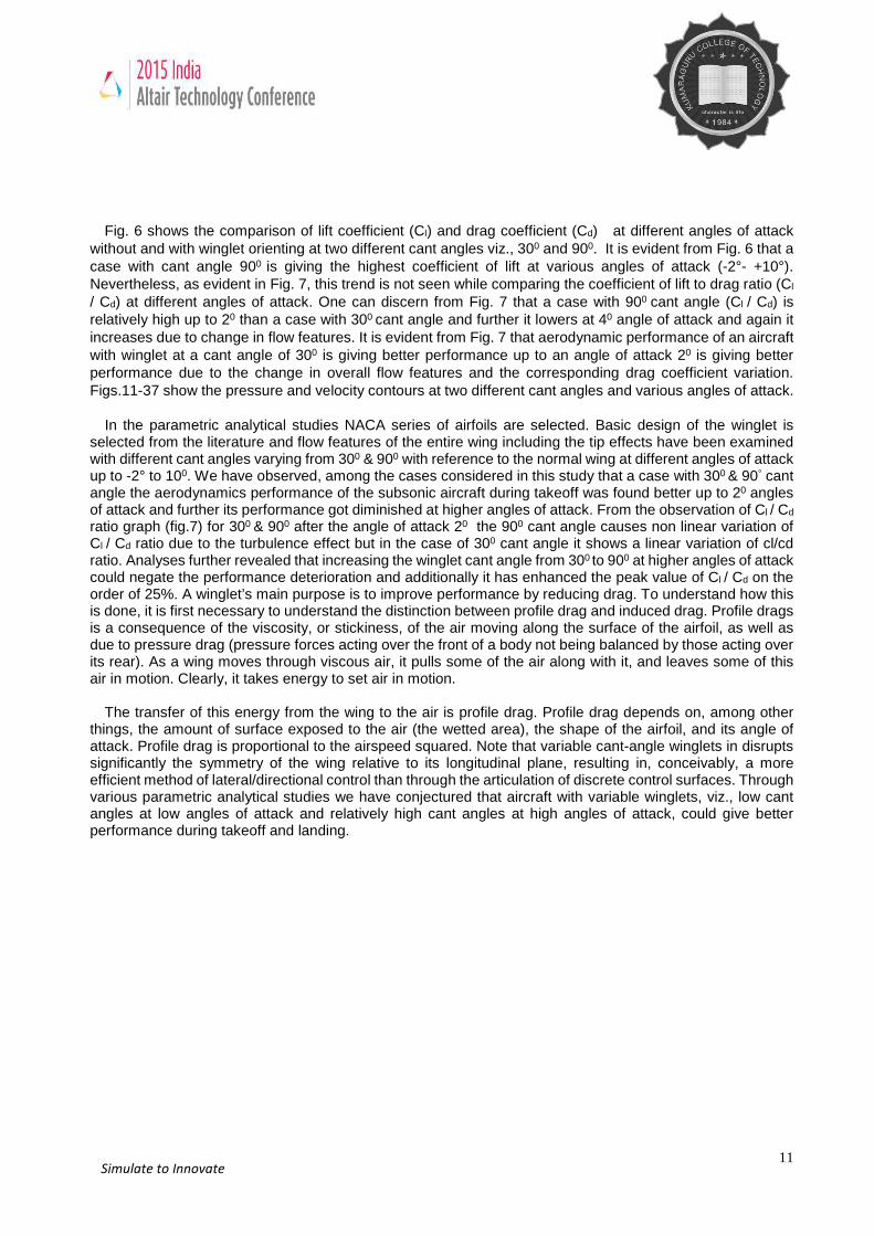
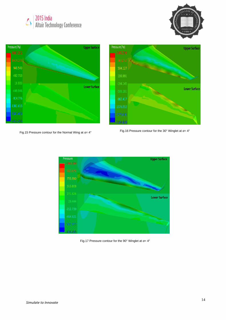
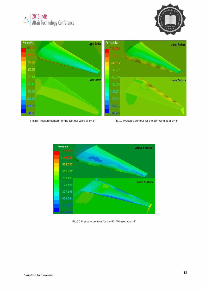
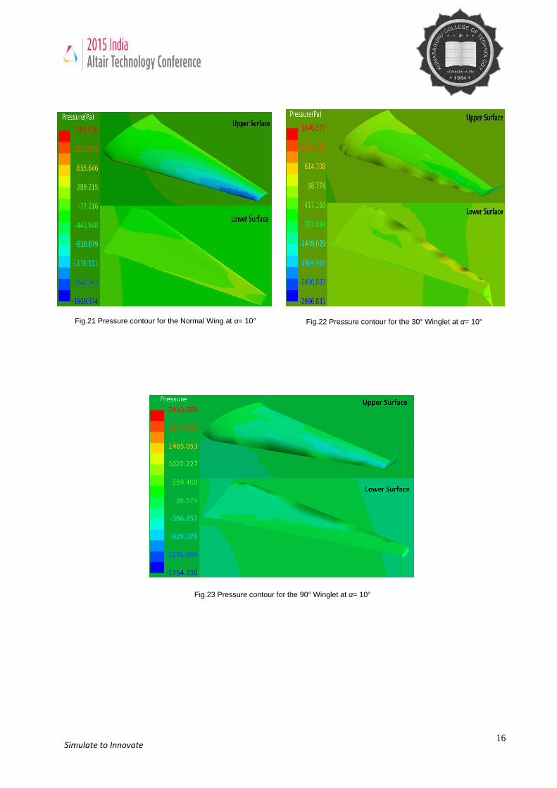
Pressure distribution over the upper and lower surface of the wing
Fig.11 Pressure contour for the Normal Wing at α= -2° Fig.12 Pressure contour for the 30° Winglet at α= -2°
Fig.13 Pressure contour for 90° Winglet at α= -2°
13 Simulate to Innovate
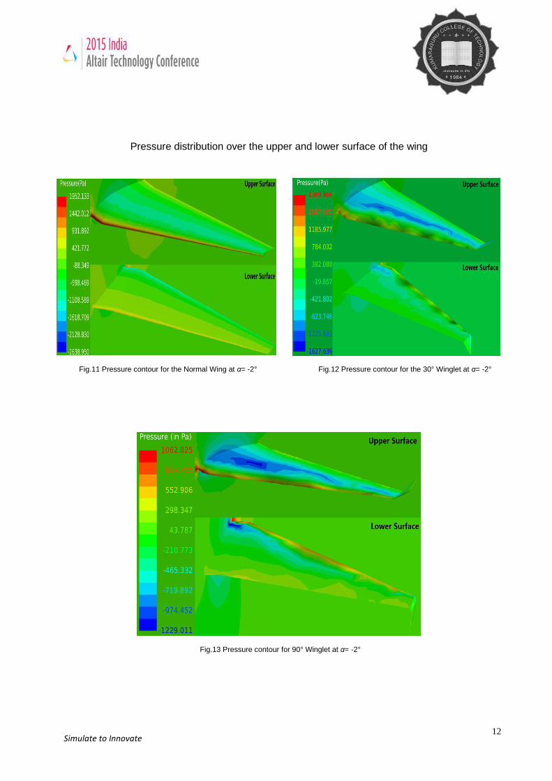
Pressure contour for the Normal Wing at α= 2° Pressure contour for the 30° Winglet at α= 2°
Fig.14 Pressure contour for the 90° Winglet at α= 2°
14 Simulate to Innovate
Fig.15 Pressure contour for the Normal Wing at α= 4° Fig.16 Pressure contour for the 30° Winglet at α= 4°
Fig.17 Pressure contour for the 90° Winglet at α= 4°
15 Simulate to Innovate
Fig.18 Pressure contour for the Normal Wing at α= 6° Fig.19 Pressure contour for the 30° Winglet at α= 6°
Fig.20 Pressure contour for the 90° Winglet at α= 6°
16 Simulate to Innovate
Fig.21 Pressure contour for the Normal Wing at α= 10° Fig.22 Pressure contour for the 30° Winglet at α= 10°
Fig.23 Pressure contour for the 90° Winglet at α= 10°
17 Simulate to Innovate
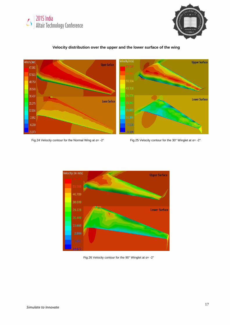
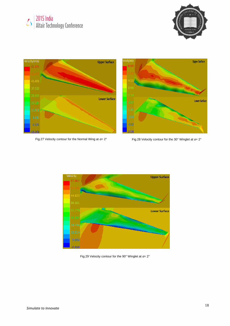
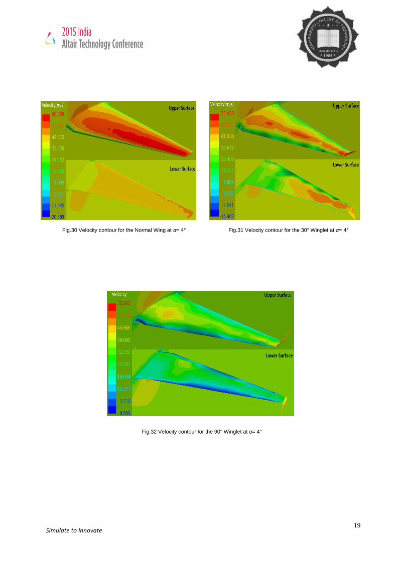
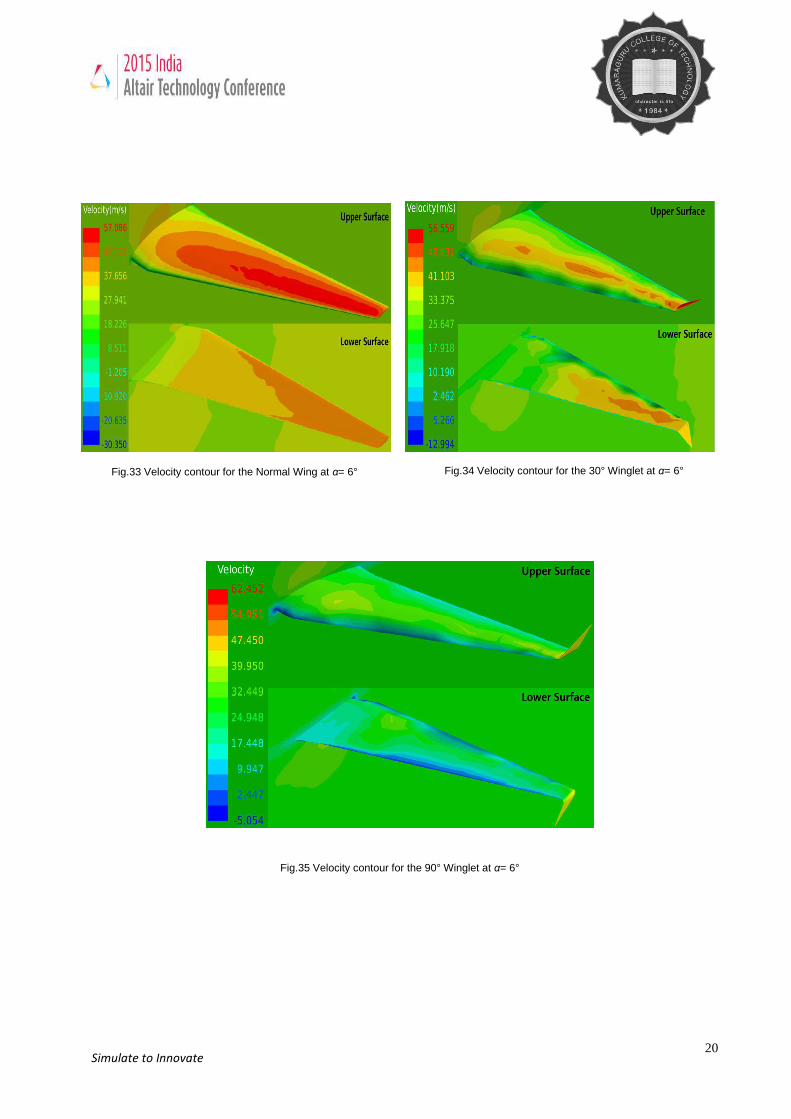
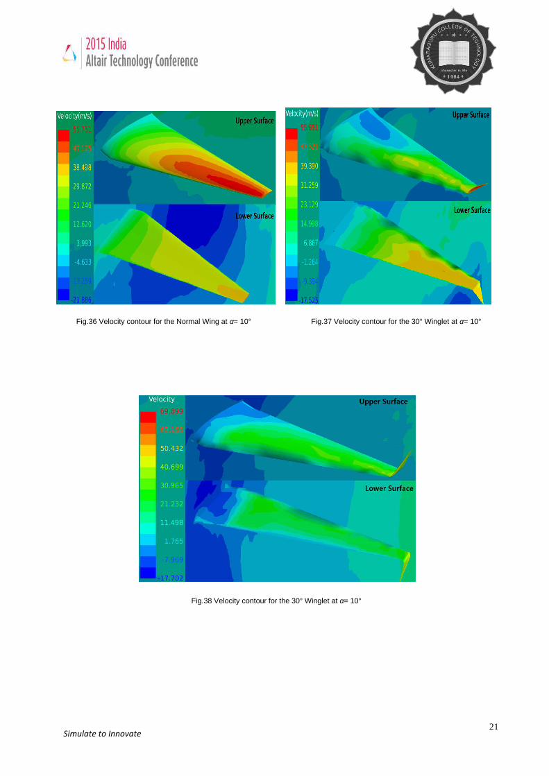
Velocity distribution over the upper and the lower surface of the wing
Fig.24 Velocity contour for the Normal Wing at α= -2° Fig.25 Velocity contour for the 30° Winglet at α= -2°
Fig.26 Velocity contour for the 90° Winglet at α= -2°
18 Simulate to Innovate
Fig.27 Velocity contour for the Normal Wing at α= 2° Fig.28 Velocity contour for the 30° Winglet at α= 2°
Fig.29 Velocity contour for the 90° Winglet at α= 2°
19 Simulate to Innovate
Fig.32 Velocity contour for the 90° Winglet at α= 4°
Fig.30 Velocity contour for the Normal Wing at α= 4° Fig.31 Velocity contour for the 30° Winglet at α= 4°
20 Simulate to Innovate
Fig.33 Velocity contour for the Normal Wing at α= 6° Fig.34 Velocity contour for the 30° Winglet at α= 6°
Fig.35 Velocity contour for the 90° Winglet at α= 6°
21 Simulate to Innovate
Fig.36 Velocity contour for the Normal Wing at α= 10° Fig.37 Velocity contour for the 30° Winglet at α= 10°
Fig.38 Velocity contour for the 30° Winglet at α= 10°
22 Simulate to Innovate
Benefits Summary By using Acusolve we could precisely observe the clear variation in the contours results at different flow condition. Observation of the pressure and velocity variation graph for the upper and lower surface of the wing, which help us to validate cl and cd using Acuprobe Acusolve is one of the powerful computational software which saves considerable time and cost. Challenges Obtaining a smooth curvature mesh at the leading edge of the wing. Plotting cl and cd graph using AcuProbe to observe the vortex formation at the tip of the wing Future Plans In future this CFD research work will be tested at cant angles form -180° to 180°. At different angles of
attacks using Acusolve as a main solver to find out the optimum cant angle for the best aerodynamic
performance of an aircraft wing
Also this design is to be modeled and to be tested in a subsonic wind tunnel and with the obtained
experimental results CFD results are to be validated.
ACKNOWLEDGEMENT:
We thank our management for providing the better computing facility to solve this huge mesh count problem
with in short period of time and also we thank Altair technical supporting team.
Conclusions The present work shows that winglets are one of the important device to achieve better aerodynamic performance of the aircraft. . This project proposes alternatives in the cant angles of the winglet from the conventional wing without winglet. An improved winglet design with at a certain cant angle will significantly yield a better performance of an aircraft by lowering the induced drag which causes tip vortices. The overall improved aerodynamic efficiency will result in reduced fuel consumption. Although performance gains achieved with winglets are only a few percent, such small differences can be of significant profit to any airline industry. Through our analytical studies we have concluded that aircraft with variable winglets, viz., low cant angles at low angles of attack and relatively high cant angles at high angles of attack, could give better performance during takeoff and landing. Winglet cant angle optimization needs to be carried out case by case. By using CFD to predict the performance of the winglets, huge amount of time and money can be saved before testing the winglet in the wind tunnel. We concluded that the investigated concept of variable-cant-angle winglets appears to be a promising alternative for improving the aerodynamic efficiency of aircraft. .
REFERENCES [1] Faye, R.; Laprete, R.; Winter, M. "Blended Winglets" Aero, No. 17., Boeing, January 2002. [2] J.D. Anderson, Fundamentals of Aerodynamics, McGraw-Hill, New York, 2011. [3] D. McLean, Understanding Aerodynamics Arguing from the Real Physics, Wiley-Blackwell, Chichester, 2013. [4] P. Panagiotou, P. Kaparos, K. Yakinthos, Winglet design and optimization for a MALE UAV using CFD, Aerospace Science and
Technology, Vol.39, December 2014, pp. 190–205. [5] P. Bourdin, A. Gatto, and M. I. Friswell. "Aircraft Control via Variable Cant-Angle Winglets", Journal of Aircraft, Vol. 45, No. 2, 2008,
pp. 414-423.
23 Simulate to Innovate
[6] Langevin, G. S. and Overbey, P., “To Reality: Winglets,” NASA Langley Research Center, October 17, 2003. [7] Bargsten, Clayton J.; Gibson, Malcolm T., NASA Innovation in Aeronautics: Select Technologies That Have Shaped Modern
Aviation, NASA/TM-2011-216987. National Aeronautics and Space Administration. August 2011, pp. 15–21. [8] M. Young, The Techincal Writers Handbook. Mill Valley, CA: University Science, 1989. [9] Faye, R.; Laprete, R.; Winter, M. "Wingtip Devices." Aero, No. 17., Boeing. [10] Air & Space Magazine, "How Things Work: Winglets". September 1, 2001. [11] Culick, F. E. C., “The Wright Brothers: First Aeronautical Engineers
and Test Pilots”, AIAA Journal, Vol. 41, No. 6, June 2003, pp. 985– 1006.
[12] A. Beechook , J. Wang “Aerodynamic Analysis of Variable Cant Angle Winglets for Improved Aircraft Performance”, Proceedings of the 19 International Conference on Automation & Computing, Brunel University, London, UK, September 2013
[13] R. Hallion, “NASA’s Contributions to Aeronautics: Aerodynamics, Structures, Propulsion, and Controls”, Vol. 1,Washington, DC: NASA SP-2010-570-Vol 1, 2010, pp. 116-118.
[14] M. K. V. Sankrithi, B.J. Frommer, “Controllable Winglets”, United States Patent Document, Patent No. US2008/0308683, 2008. [15] R. H. Grant, “Retractable Multiple Winglets”, United States Patent Document, Patent No. US2007/0262205, 2007. [16] M. A. Azlin, C. F. Mat Taib, S. Kasolang, F. H. Muhammad, “CFD Analysis of Winglets at Low Subsonic Flow”, World Congress on
Engineering 2011, Vol. 1, 2011, pp. 1-5 [17] A. Hossain, A. Rahman, P. Iqbal, M. Ariffin, M. Mazian, “Drag Analysis of an Aircraft Wing Model with and without Bird Feather like
Winglet”, International Journal of Aerospace and Mechanical Engineering , 6:1, 2012, pp. 8-13 [18] P. Marks, “Morphing Winglets Make for Greener Aircraft”, NewScientist , Issue 2692, 2009 [19] Jha, A. K., and KudvaSmart, J. N., “Morphing Aircraft Concepts, Classifications, and Challenges,” Structures and Materials 2004:
Industrial and Commercial Applications of Smart Structures Technologies, Proceedings of SPIE Vol. 5388, International Society for Optical Engineering, Bellingham, WA, 2004, pp. 213–224.
[20] Sanders, B., Eastep, F. E., and Forster, E., “Aerodynamic and Aeroelastic Characteristics of Wings with Conformal Control Surfaces for Morphing Aircraft,” Journal of Aircraft, Vol. 40, No. 1, Jan.–Feb. 2003, pp. 94–99.
[21] Raymer, D. P., Aircraft Design: A Conceptual Approach, AIAA Education Series, AIAA, Reston, VA, 2006, p. 506. [22] Bae, J. S., Seigler, T. M., and Inman, D. J., “Aerodynamic and Static Aeroelastic Characteristics of a Variable-Span Morphing Wing,”
Journal of Aircraft, Vol. 42, No. 2, 2005, pp. 528–534. [23] A.E. Von Doenhoff, “Investigation of the boundary layer about a symmetrical airfoil in a wind tunnel of low turbulence”, Langley
Memorial Aeronautical Laboratory, W.R. No. L.507, NACA, 1940. [24] Henry, J. J., Blondeau, J. E., and Pines, D. J., “Stability Analysis for
UAVs with a Variable Aspect Ratio Wing,” AIAA Paper 2005-2044,April 2005. [25] Phil Croucher , Jar Professional Pilot Studies. Electrocution. 2005, pp. 2–11. ISBN 978-0-9681928-2-5. .


![Commercial Aircraft Performance Graduate … using CATIA V5 R21 [6]. ... CFD simulation by FLUENT software using finite ... 4.1 Pressure field behind wing](https://img.pdfslide.us/doc/110x75/5b00d17d7f8b9a89598d3a49/commercial-aircraft-performance-graduate-using-catia-v5-r21-6-cfd-simulation.jpg)