Embed Size (px)
Citation preview
AAiirrccrraafftt IInnffoorrmmaattiioonn BBooookklleett
CCeessssnnaa 118822TT
VVHH--SSRREE
Last revised: 11 November 2013
© 2013 Airborne Aviation Pty Ltd
www.airborne-aviation.com.au

THIS PAGE INTENTIONALLY LEFT BLANK
Contents
Aircraft Overview
General Information ........................................................................... 1
Equipment and Features ..................................................................... 1
Recency and Restrictions ..................................................................... 1
Panel Photo ....................................................................................... 1
Performance – Specifications
Summary of Aircraft Performance and Specifications .............................. 2
Operating Limitations
Airspeeds .......................................................................................... 3
Power Plant ....................................................................................... 4
Fuel System ...................................................................................... 4
Tyre Pressures ................................................................................... 4
Manoeuvre / Load Limits ..................................................................... 4
Weight & Balance
Weight and Moment Tabulations .......................................................... 5
Loading Arrangements ........................................................................ 6
Centre of Gravity Moment Envelope ...................................................... 7
Sample Configurations ........................................................................ 8
Performance Charts
Takeoff Distances at 3100lbs (MTOW) ................................................... 9
Landing Distances at 2950lbs (MLW) ................................................... 10
Checklists
Normal Operations ............................................................................ 11
Emergency Operations ....................................................................... 22
Notes
Your Personal Notes .......................................................................... 29
NOTICE
The information and figures contained in this booklet are to be used for general purposes only. This document is
not a substitute for the approved aeroplane flight manual.
Report errors to [email protected]
VH-SRE (Version: 20131111) - 1 - www.airborne-aviation.com.au
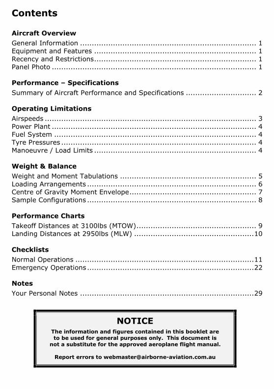
Aircraft Overview
This C182T is one of our new generation Cessna’s.
It is ideal for advanced flight training (CPL) and CSU endorsements for
pilots who are familiar with C172’s. With long endurance, big load carrying
abilities and a high cruise speed this aircraft is great for cross-country
touring.
Equipment & Features
- Dual NAV/COM (One with glide-slope)
- ADF Receiver
- Colour GPS (KLN 94)
- Multifunctional Display
- Transponder
- Dual axis autopilot with altitude pre-select
- Leather Seats
Recency & Restrictions
Private Hire: Company check flight.
Dual training: No restrictions.
Recency: Flown type (or similar) in last 45 days.
Panel Photo
VH-SRE (Version: 20131111) - 2 - www.airborne-aviation.com.au
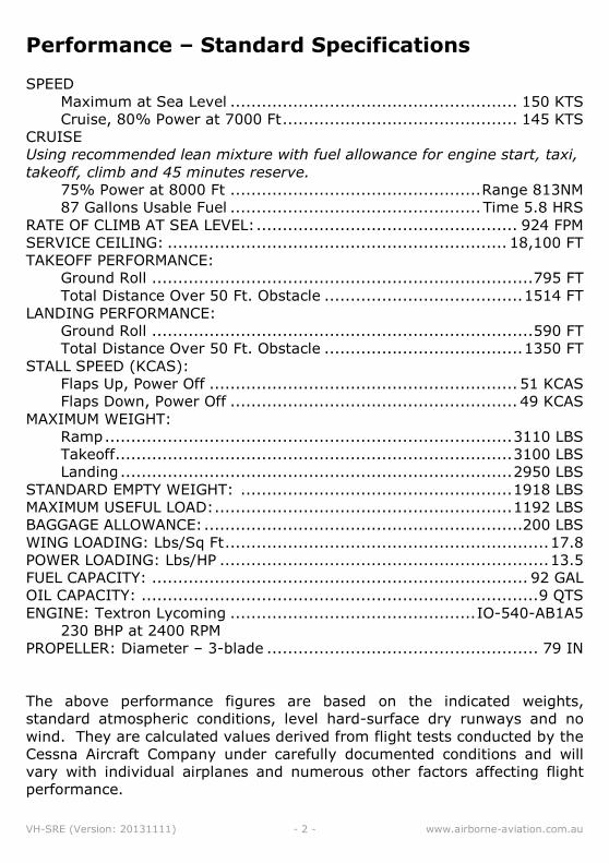
Performance – Standard Specifications
SPEED
Maximum at Sea Level ....................................................... 150 KTS
Cruise, 80% Power at 7000 Ft ............................................. 145 KTS
CRUISE
Using recommended lean mixture with fuel allowance for engine start, taxi,
takeoff, climb and 45 minutes reserve.
75% Power at 8000 Ft ................................................ Range 813NM
87 Gallons Usable Fuel ................................................ Time 5.8 HRS
RATE OF CLIMB AT SEA LEVEL: .................................................. 924 FPM
SERVICE CEILING: ................................................................. 18,100 FT
TAKEOFF PERFORMANCE:
Ground Roll ......................................................................... 795 FT
Total Distance Over 50 Ft. Obstacle ...................................... 1514 FT
LANDING PERFORMANCE:
Ground Roll ......................................................................... 590 FT
Total Distance Over 50 Ft. Obstacle ...................................... 1350 FT
STALL SPEED (KCAS):
Flaps Up, Power Off ........................................................... 51 KCAS
Flaps Down, Power Off ....................................................... 49 KCAS
MAXIMUM WEIGHT:
Ramp .............................................................................. 3110 LBS
Takeoff ............................................................................ 3100 LBS
Landing ........................................................................... 2950 LBS
STANDARD EMPTY WEIGHT: .................................................... 1918 LBS
MAXIMUM USEFUL LOAD: ......................................................... 1192 LBS
BAGGAGE ALLOWANCE: .............................................................200 LBS
WING LOADING: Lbs/Sq Ft .............................................................. 17.8
POWER LOADING: Lbs/HP ............................................................... 13.5
FUEL CAPACITY: ........................................................................ 92 GAL
OIL CAPACITY: ............................................................................ 9 QTS
ENGINE: Textron Lycoming ............................................... IO-540-AB1A5
230 BHP at 2400 RPM
PROPELLER: Diameter – 3-blade .................................................... 79 IN
The above performance figures are based on the indicated weights,
standard atmospheric conditions, level hard-surface dry runways and no
wind. They are calculated values derived from flight tests conducted by the
Cessna Aircraft Company under carefully documented conditions and will
vary with individual airplanes and numerous other factors affecting flight
performance.
VH-SRE (Version: 20131111) - 3 - www.airborne-aviation.com.au
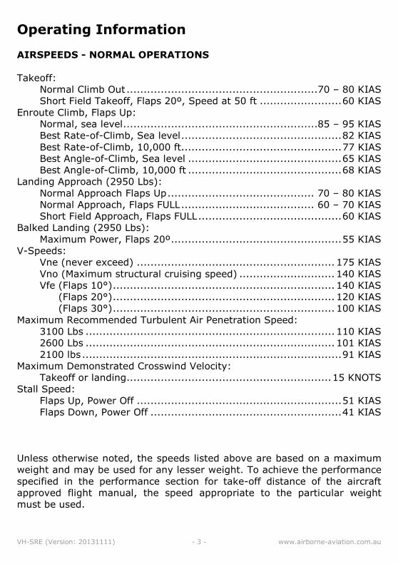
Operating Information
AIRSPEEDS - NORMAL OPERATIONS
Takeoff:
Normal Climb Out ........................................................70 – 80 KIAS
Short Field Takeoff, Flaps 20º, Speed at 50 ft ........................ 60 KIAS
Enroute Climb, Flaps Up:
Normal, sea level .........................................................85 – 95 KIAS
Best Rate-of-Climb, Sea level ............................................... 82 KIAS
Best Rate-of-Climb, 10,000 ft............................................... 77 KIAS
Best Angle-of-Climb, Sea level ............................................. 65 KIAS
Best Angle-of-Climb, 10,000 ft ............................................. 68 KIAS
Landing Approach (2950 Lbs):
Normal Approach Flaps Up ........................................... 70 – 80 KIAS
Normal Approach, Flaps FULL ....................................... 60 – 70 KIAS
Short Field Approach, Flaps FULL .......................................... 60 KIAS
Balked Landing (2950 Lbs):
Maximum Power, Flaps 20º .................................................. 55 KIAS
V-Speeds:
Vne (never exceed) .......................................................... 175 KIAS
Vno (Maximum structural cruising speed) ............................ 140 KIAS
Vfe (Flaps 10°) ................................................................. 140 KIAS
Vfe (Flaps 20°) ................................................................. 120 KIAS
Vfe (Flaps 30°) ................................................................. 100 KIAS
Maximum Recommended Turbulent Air Penetration Speed:
3100 Lbs ......................................................................... 110 KIAS
2600 Lbs ......................................................................... 101 KIAS
2100 lbs ............................................................................ 91 KIAS
Maximum Demonstrated Crosswind Velocity:
Takeoff or landing ............................................................ 15 KNOTS
Stall Speed:
Flaps Up, Power Off ............................................................ 51 KIAS
Flaps Down, Power Off ........................................................ 41 KIAS
Unless otherwise noted, the speeds listed above are based on a maximum
weight and may be used for any lesser weight. To achieve the performance
specified in the performance section for take-off distance of the aircraft
approved flight manual, the speed appropriate to the particular weight
must be used.
VH-SRE (Version: 20131111) - 4 - www.airborne-aviation.com.au
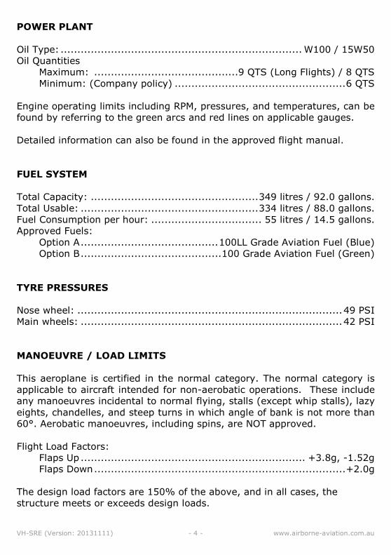
POWER PLANT
Oil Type: ........................................................................ W100 / 15W50
Oil Quantities
Maximum: ...........................................9 QTS (Long Flights) / 8 QTS
Minimum: (Company policy) ................................................... 6 QTS
Engine operating limits including RPM, pressures, and temperatures, can be
found by referring to the green arcs and red lines on applicable gauges.
Detailed information can also be found in the approved flight manual.
FUEL SYSTEM
Total Capacity: .................................................. 349 litres / 92.0 gallons.
Total Usable: ..................................................... 334 litres / 88.0 gallons.
Fuel Consumption per hour: ................................. 55 litres / 14.5 gallons.
Approved Fuels:
Option A ......................................... 100LL Grade Aviation Fuel (Blue)
Option B .......................................... 100 Grade Aviation Fuel (Green)
TYRE PRESSURES
Nose wheel: ............................................................................... 49 PSI
Main wheels: .............................................................................. 42 PSI
MANOEUVRE / LOAD LIMITS
This aeroplane is certified in the normal category. The normal category is
applicable to aircraft intended for non-aerobatic operations. These include
any manoeuvres incidental to normal flying, stalls (except whip stalls), lazy
eights, chandelles, and steep turns in which angle of bank is not more than
60°. Aerobatic manoeuvres, including spins, are NOT approved.
Flight Load Factors:
Flaps Up ................................................................... +3.8g, -1.52g
Flaps Down ........................................................................... +2.0g
The design load factors are 150% of the above, and in all cases, the
structure meets or exceeds design loads.
VH-SRE (Version: 20131111) - 5 - www.airborne-aviation.com.au
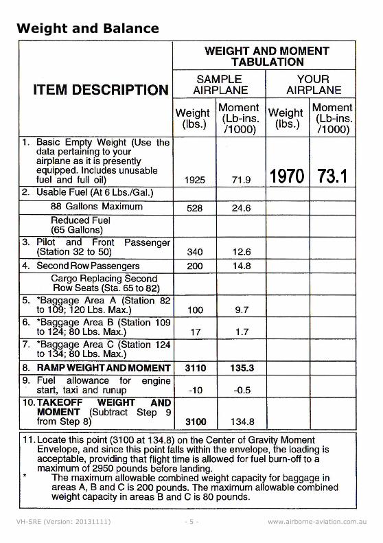
Weight and Balance
VH-SRE (Version: 20131111) - 6 - www.airborne-aviation.com.au
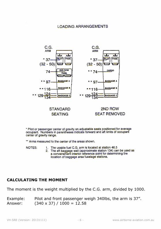
CALCULATING THE MOMENT
The moment is the weight multiplied by the C.G. arm, divided by 1000.
Example: Pilot and front passenger weigh 340lbs, the arm is 37”.
Answer: (340 x 37) / 1000 = 12.58
VH-SRE (Version: 20131111) - 7 - www.airborne-aviation.com.au
VH-SRE (Version: 20131111) - 8 - www.airborne-aviation.com.au
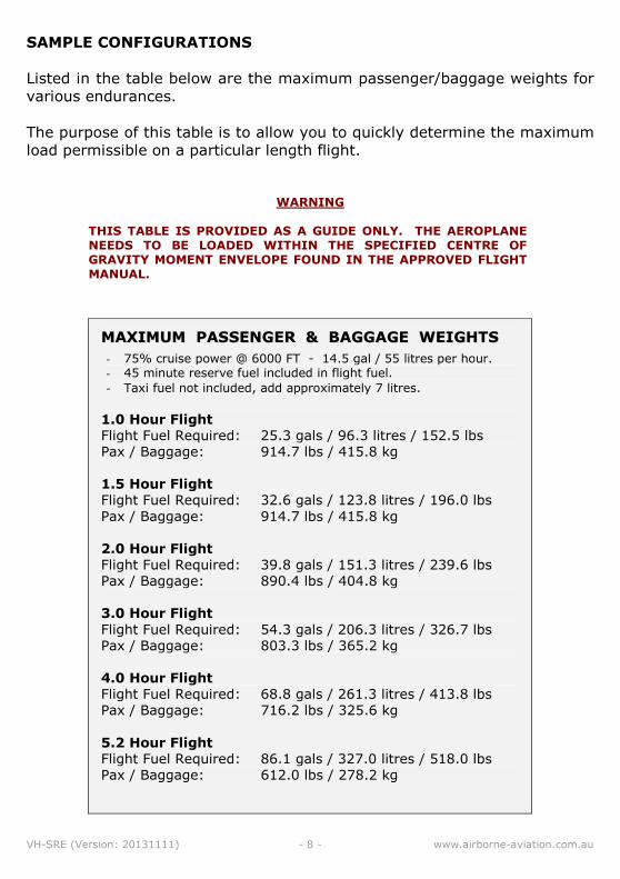
SAMPLE CONFIGURATIONS
Listed in the table below are the maximum passenger/baggage weights for
various endurances.
The purpose of this table is to allow you to quickly determine the maximum
load permissible on a particular length flight.
WARNING
THIS TABLE IS PROVIDED AS A GUIDE ONLY. THE AEROPLANE NEEDS TO BE LOADED WITHIN THE SPECIFIED CENTRE OF GRAVITY MOMENT ENVELOPE FOUND IN THE APPROVED FLIGHT MANUAL.
MMAAXXIIMMUUMM PPAASSSSEENNGGEERR && BBAAGGGGAAGGEE WWEEIIGGHHTTSS
- 75% cruise power @ 6000 FT - 14.5 gal / 55 litres per hour. - 45 minute reserve fuel included in flight fuel.
- Taxi fuel not included, add approximately 7 litres.
1.0 Hour Flight Flight Fuel Required: 25.3 gals / 96.3 litres / 152.5 lbs
Pax / Baggage: 914.7 lbs / 415.8 kg
1.5 Hour Flight Flight Fuel Required: 32.6 gals / 123.8 litres / 196.0 lbs
Pax / Baggage: 914.7 lbs / 415.8 kg
2.0 Hour Flight Flight Fuel Required: 39.8 gals / 151.3 litres / 239.6 lbs
Pax / Baggage: 890.4 lbs / 404.8 kg
3.0 Hour Flight
Flight Fuel Required: 54.3 gals / 206.3 litres / 326.7 lbs
Pax / Baggage: 803.3 lbs / 365.2 kg
4.0 Hour Flight Flight Fuel Required: 68.8 gals / 261.3 litres / 413.8 lbs
Pax / Baggage: 716.2 lbs / 325.6 kg
5.2 Hour Flight Flight Fuel Required: 86.1 gals / 327.0 litres / 518.0 lbs
Pax / Baggage: 612.0 lbs / 278.2 kg
VH-SRE (Version: 20131111) - 9 - www.airborne-aviation.com.au
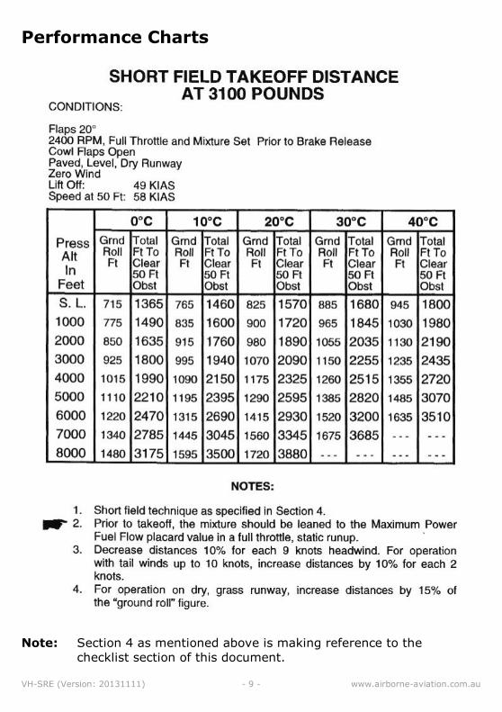
Performance Charts
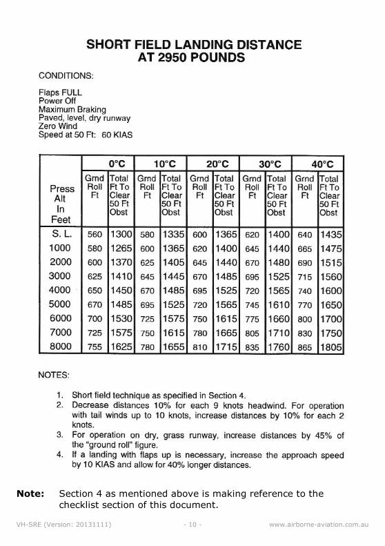
Note: Section 4 as mentioned above is making reference to the
checklist section of this document.
VH-SRE (Version: 20131111) - 10 - www.airborne-aviation.com.au
Note: Section 4 as mentioned above is making reference to the
checklist section of this document.
VH-SRE (Version: 20131111) - 11 - www.airborne-aviation.com.au
Checklists – Normal Operations
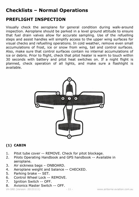
PREFLIGHT INSPECTION
Visually check the aeroplane for general condition during walk-around
inspection. Aeroplane should be parked in a level ground attitude to ensure
that fuel drain valves allow for accurate sampling. Use of the refuelling
steps and assist handles will simplify access to the upper wing surfaces for
visual checks and refuelling operations. In cold weather, remove even small
accumulations of frost, ice or snow from wing, tail and control surfaces.
Also, make sure that control surfaces contain no internal accumulations of
ice or debris. Prior to flight, check that pitot heater is warm to touch within
30 seconds with battery and pitot heat switches on. If a night flight is
planned, check operation of all lights, and make sure a flashlight is
available.
(1) CABIN
1. Pitot tube cover -- REMOVE. Check for pitot blockage.
2. Pilots Operating Handbook and GPS handbook -- Available in
aeroplane.
3. Air sickness bags – ONBOARD.
4. Aeroplane weight and balance -- CHECKED.
5. Parking brake -- SET.
6. Control Wheel Lock -- REMOVE.
7. Ignition Switch -- OFF.
8. Avionics Master Switch -- OFF.
VH-SRE (Version: 20131111) - 12 - www.airborne-aviation.com.au
WARNING
WHEN TURNING ON THE MASTER SWITCH, USING AN EXTERNAL POWER SOURCE, OR PULLING THE PROPELLER THROUGH BY HAND, TREAT THE PROPELLER AS IF THE IGNITION SWITCH WERE ON. DO NOT STAND, NOR ALLOW ANYONE ELSE TO STAND, WITHIN THE ARC OF THE PROPELLER, SINCE A LOOSE OR BROKEN WIRE OR A COMPONENT MALFUNCTION COULD CAUSE THE PROPELLER TO ROTATE.
9. Master Switch (ALT and BAT) -- ON.
10. Fuel QTY (L and R) -- CHECK. 11. LOW FUEL L and LOW FUEL R Annunciators -- Verify Annunciator OFF. 12. Avionics Master Switch -- ON. 13. Avionics Cooling Fan -- CHECK AUDIBLY FOR OPERATION. 14. Avionics Master Switch -- OFF. 15. Static Pressure Alternate Source Valve -- OFF. 16. Annunciator Panel Test Switch -- PLACE AND HOLD IN TST POSITION
and ensure all amber and red annunciators illuminate.
17. Annunciator Panel Test Switch -- RELEASE. Check that appropriate annunciators remain on.
NOTE
When Master Switch is turned ON, some annunciators will
flash for approximately 10 seconds before illuminating
steadily. When panel TEST switch is toggled up and held
in position, all remaining lights will flash until the switch is
released
18. Fuel Selector Valve -- BOTH. 19. Flaps – FULLY EXTEND. 20. Pitot Heat -- ON (Carefully check that pitot tube is warm to touch
within 30 seconds.)
21. Pitot Heat -- OFF. 22. Master Switch -- OFF. 23. Elevator and Rudder Trim Controls -- TAKEOFF position. 24. Fire Extinguisher -- CHECK verify green arc.
(2) EMPENNAGE
1. Rudder Gust Lock -- REMOVE.
2. Tail Tie-down -- DISCONNECT.
3. Control Surfaces -- CHECK freedom of movement and security.
4. Trim Tab -- CHECK security.
5. Antennas -- CHECK for security of attachment and general condition.
VH-SRE (Version: 20131111) - 13 - www.airborne-aviation.com.au
(3) RIGHT WING Trailing Edge
1. Flap -- CHECK for security and condition.
2. Aileron -- CHECK freedom of movement and security.
(4) RIGHT WING
1. Wing Tie-down -- DISCONNECT.
2. Fuel Tank Vent Opening -- CHECK for stoppage.
3. Main Wheel Tire -- CHECK for proper inflation and general condition
(weather checks, tread depth, and wear etc…).
WARNING
IF, AFTER REPEATED SAMPLING, EVIDENCE OF CONTAMINATION STILL EXISTS, THE AEROPLANE SHOULD NOT BE FLOWN. TANKS SHOULD BE DRAINED AND SYSTEM PURGED BY QUALIFIED MAINENANCE PERSONNEL. ALL EVIDENCE OF CONTAMINATION MUST BE REMOVED BEFORE FURTHER FLIGHT.
4. Fuel Tank Sump Quick Drain Valves -- DRAIN at least a cupful of fuel
(using sampler cup) from each sump location to check for water,
sediment, and proper fuel grade before each flight and after each
refuelling. If water is observed, take further samples until clear and
then gently rock wings and lower tail to the ground to move any
additional contaminants to the sampling points. Take repeated
samples from all fuel drain points until all contamination has been
removed. If contaminants are still present, refer to above WARNING
and do not fly aeroplane.
5. Fuel quantity -- CHECK VISUALLY for desired level.
6. Fuel Filler Cap -- SECURE AND VENT UNOBSTRUCTED.
(5) NOSE
1. Right Static Source Opening -- CHECK for blockage.
2. Fuel Selector Quick Drain Valve (located on bottom of fuselage below
the fuel selector valve) -- DRAIN at least a cupful of fuel (using
sampler cup) from valve to check for water, sediment, and proper fuel
grade before each flight and after each refuelling. If water is observed,
take further samples until clear and then gently rock wings and lower
tail to the ground to move any additional contaminants to the sampling
points. Take repeated samples from all fuel drain points until all
contamination has been removed. If contaminants are still present,
refer to above WARNING and do not fly aeroplane.
VH-SRE (Version: 20131111) - 14 - www.airborne-aviation.com.au
3. Engine Oil Dipstick/Filler Cap -- CHECK oil level, than check
dipstick/filler cap SECURE. Do not operate with less than six quarts.
Fill to nine quarts for extended flights.
4. Engine Cooling Air Inlets -- CLEAR of obstructions.
5. Propeller and spinner -- CHECK for nicks and security.
6. Air Filter -- CHECK for restrictions by dust or other foreign matter.
7. Nose wheel strut and tyre -- CHECK for proper inflation of strut and
general condition (weather checks, tread depth and wear) of tyre.
8. Left static source opening -- CHECK for blockage.
(6) LEFT WING
1. Fuel Quantity -- CHECK VISUALLY for desired level.
2. Fuel Filler Cap -- SECURE AND VENT UNOBSTRUCTED.
3. Fuel Tank Sump Quick Drain Valves -- DRAIN at least a cupful of fuel
(using a sampler cup) from each sump location to check for water,
sediment and proper fuel grade before each flight and after each
refuelling. If water is observed, take further samples until clear and
then gently rock wings and lower tail to the ground to move any
additional contaminants to the sampling points. Take repeated
samples from all fuel drain points until all contamination has been
removed. If contaminants are still present do not fly aeroplane.
4. Main Wheel Tyre -- CHECK for proper inflation and general condition
(weather checks, tread depth and wear, etc).
(7) LEFT WING Leading Edge
1. Fuel Tank Vent Opening -- CHECK for blockage.
2. Stall Warning System -- CHECK vane for freedom of movement. To
check the system, place the vane upward; a sound from the warning
horn with the Master Switch ON will confirm system operation.
3. Wing Tie-Down -- DISCONNECT.
4. Landing/Taxi Lights -- CHECK for condition and cleanliness of cover.
(8) LEFT WING Trailing edge
1. Aileron -- CHECK for freedom of movement and security.
2. Flap -- CHECK for security and condition.
3. Baggage door -- CHECK (lock with key)
VH-SRE (Version: 20131111) - 15 - www.airborne-aviation.com.au
BEFORE STARTING ENGINE
1. Pre-flight Inspection – COMPLETE
2. Aircraft Dispatch -- COMPLETE / AUTHORISED.
3. Running Sheet Figures -- COMPLETE.
4. Maintenance Release -- CHECKED.
5. Air Sickness Bags -- AVAILABLE.
6. Passenger Briefing -- COMPLETE
7. Seats, Seatbelts, Shoulder Harnesses -- ADJUST and LOCK. Ensure
inertia reel locking.
8. Brakes -- TEST and PARKING BRAKE SET
9. Cowl Flaps -- OPEN.
10. Circuit Breakers -- CHECK IN. 11. Fuel Selector Valve -- BOTH. 12. Electrical Equipment -- OFF. 13. Master Switch -- ON 14. ATIS / Clearance -- OBTAIN as required.
a. Master Switch -- ON
b. Avionics Master Switch -- ON.
c. Radios/Navaids -- ON, set as required.
d. ATIS / Clearance -- OBTAIN.
WARNING
THE AVIONICS MASTER SWITCH MUST BE OFF DURING ENGINE START TO PREVENT POSSIBLE DAMAGE TO AVIONICS.
15. Avionics Master Switch -- OFF.
STARTING ENGINE (With Battery)
1. Throttle -- OPEN ¼ INCH (5mm).
2. Propeller -- HIGH RPM (Fully in).
3. Mixture -- IDLE CUT OFF.
4. Propeller Area -- CLEAR.
5. Master switch – ON.
VH-SRE (Version: 20131111) - 16 - www.airborne-aviation.com.au
NOTE
If engine is warm omit priming procedure in steps
6, 7 & 8.
6. Auxiliary Fuel Pump Switch -- ON.
7. Mixture - ADVANCE to full rich for 3 to 4 seconds, then return to IDLE
CUT OFF position.
8. Auxiliary Fuel Pump -- OFF.
9. Confirm area around aircraft is clear -- call “CLEAR PROP!”
10. Ignition Switch -- START (release when engine starts). 11. Mixture -- ADVANCE smoothly to RICH when engine fires. 12. Set throttle -- 1000 RPM.
NOTE
If engine floods, turn off auxiliary fuel pump, place
mixture in idle cut off, open throttle ½ to full, and crank
engine. When engine fires, advance mixture to full rich
and retard throttle promptly
13. Oil Pressure -- CHECK. Confirm rising within 30 seconds or shut down. 14. AMPS/VOLTS -- Check for discharge. 15. Navigation lights and Flashing Beacon -- ON as required. 16. Avionics Master Switch -- ON 17. Radios/Navaids -- ON. Set as required 18. Flaps -- RETRACT.
STARTING ENGINE (With External Power)
Procedures for starting the engine with external power are similar to
starting with battery power.
Insert two additional steps to the STARTING ENGINE (with battery)
checklist:
4.1 External Power -- CONNECT to Aeroplane receptacle.
13.1 External Power -- DISCONNECT from aeroplane receptacle.
TAXYING
1. Brakes -- CHECK.
2. Instruments -- CHECK indications in correct sense.
Flight Controls – AS REQUIRED (Column AFT or as required due wind)
VH-SRE (Version: 20131111) - 17 - www.airborne-aviation.com.au
BEFORE TAKEOFF
1. Parking Brake -- SET.
2. Passenger Seat Backs -- MOST UPRIGHT POSITION.
3. Seats, Seatbelts and Shoulder Harnesses -- CHECK SECURE.
4. Cabin Doors -- CLOSED and LOCKED.
5. Flight Controls -- FULL FREE and CORRECT movement.
6. Flight Instruments -- CHECK and SET.
7. Fuel Quantity -- CHECK.
8. Mixture -- RICH.
9. Fuel Selector Valve -- RECHECK BOTH.
10. Elevator Trim and Rudder Trim -- SET for takeoff. 11. Throttle -- 1800 RPM.
a. Magnetos -- CHECK. RPM drop should not exceed 175 RPM on
either magneto or 50 RPM differential between Magnetos. Confirm
on BOTH.
b. Propeller -- CYCLE from high to low RPM; return to high RPM.
Repeat. Confirm in high RPM.
c. Vacuum Gauge -- CHECK.
d. Engine Instruments and Ammeter -- CHECK.
12. Annunciator Panel -- Ensure no annunciators are illuminated. 13. Throttle -- CHECK idle. 14. Throttle -- 800-1000 RPM. 15. Throttle Friction Lock -- ADJUST. 16. Radios and Avionics -- SET. 17. Autopilot -- OFF. 18. Wing Flaps -- SET for Takeoff (0º normal, 20º short field). 19. Cowl Flaps -- OPEN. 20. Self Brief -- COMPLETE (Aborted T/O, engine failure, TEM) 21. Brakes -- RELEASE.
HOLDING POINT CLEAR CHECKS
1. C - Clear approaches (final, base and RWY?)
2. L - Lights: Landing, Taxi, Strobes - ON (Nav - if required, eg. NVFR)
3. E - Engine: T&P green, flaps – set as required
4. A - ALT – set on TRANSPONDER and (3000 or 1200)
5. R - Radio – Frequency set, volume tested, request clearance.
VH-SRE (Version: 20131111) - 18 - www.airborne-aviation.com.au
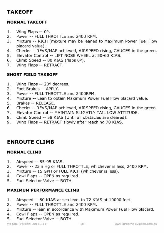
TAKEOFF
NORMAL TAKEOFF
1. Wing Flaps -- 0º.
2. Power -- FULL THROTTLE and 2400 RPM.
3. Mixture -- RICH (mixture may be leaned to Maximum Power Fuel Flow
placard value).
4. Checks -- REVS/MAP achieved, AIRSPEED rising, GAUGES in the green.
5. Elevator Control -- LIFT NOSE WHEEL at 50-60 KIAS.
6. Climb Speed -- 80 KIAS (flaps 0º).
7. Wing Flaps -- RETRACT.
SHORT FIELD TAKEOFF
1. Wing Flaps -- 20º degrees.
2. Foot Brakes -- APPLY.
3. Power -- FULL THROTTLE and 2400RPM.
4. Mixture -- Lean to obtain Maximum Power Fuel Flow placard value.
5. Brakes -- RELEASE.
6. Checks -- REVS/MAP achieved, AIRSPEED rising, GAUGES in the green.
7. Elevator Control -- MAINTAIN SLIGHTLY TAIL LOW ATTITUDE.
8. Climb Speed -- 58 KIAS (Until all obstacles are cleared).
9. Wing Flaps -- RETRACT slowly after reaching 70 KIAS.
ENROUTE CLIMB
NORMAL CLIMB
1. Airspeed -- 85-95 KIAS.
2. Power -- 23in Hg or FULL THROTTLE, whichever is less, 2400 RPM.
3. Mixture -- 15 GPH or FULL RICH (whichever is less).
4. Cowl Flaps -- OPEN as required.
5. Fuel Selector Valve -- BOTH.
MAXIMUM PERFORMANCE CLIMB
1. Airspeed -- 80 KIAS at sea level to 72 KIAS at 10000 feet.
2. Power -- FULL THROTTLE and 2400 RPM.
3. Mixture -- lean in accordance with Maximum Power Fuel Flow placard.
4. Cowl Flaps -- OPEN as required.
5. Fuel Selector Valve -- BOTH.
VH-SRE (Version: 20131111) - 19 - www.airborne-aviation.com.au
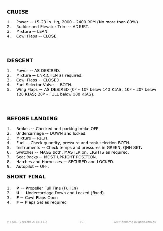
CRUISE
1. Power -- 15-23 in. Hg, 2000 - 2400 RPM (No more than 80%).
2. Rudder and Elevator Trim -- ADJUST.
3. Mixture -- LEAN.
4. Cowl Flaps -- CLOSE.
DESCENT
1. Power -- AS DESIRED.
2. Mixture -- ENRICHEN as required.
3. Cowl Flaps -- CLOSED.
4. Fuel Selector Valve -- BOTH.
5. Wing Flaps -- AS DESIRED (0º - 10º below 140 KIAS; 10º - 20º below
120 KIAS; 20º - FULL below 100 KIAS).
BEFORE LANDING
1. Brakes -- Checked and parking brake OFF.
2. Undercarriage -- DOWN and locked.
3. Mixture -- RICH.
4. Fuel -- Check quantity, pressure and tank selection BOTH.
5. Instruments -- Check temps and pressures in GREEN, QNH SET.
6. Switches -- MAGS both, MASTER on, LIGHTS as required.
7. Seat Backs -- MOST UPRIGHT POSITION.
8. Hatches and Harnesses -- SECURED and LOCKED.
9. Autopilot -- OFF.
SHORT FINAL 1. P -- Propeller Full Fine (Full In)
2. U -- Undercarriage Down and Locked (fixed).
3. F -- Cowl Flaps Open
4. F -- Flaps Set as required
VH-SRE (Version: 20131111) - 20 - www.airborne-aviation.com.au
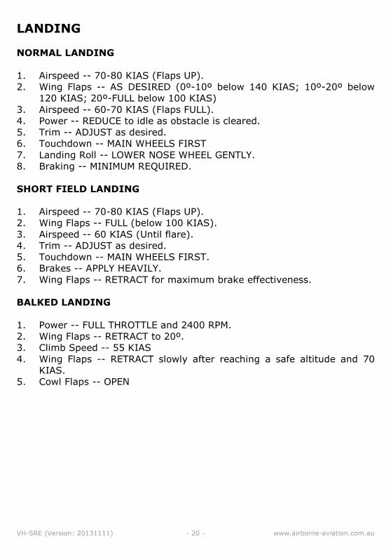
LANDING
NORMAL LANDING
1. Airspeed -- 70-80 KIAS (Flaps UP).
2. Wing Flaps -- AS DESIRED (0º-10º below 140 KIAS; 10º-20º below
120 KIAS; 20º-FULL below 100 KIAS)
3. Airspeed -- 60-70 KIAS (Flaps FULL).
4. Power -- REDUCE to idle as obstacle is cleared.
5. Trim -- ADJUST as desired.
6. Touchdown -- MAIN WHEELS FIRST
7. Landing Roll -- LOWER NOSE WHEEL GENTLY.
8. Braking -- MINIMUM REQUIRED.
SHORT FIELD LANDING
1. Airspeed -- 70-80 KIAS (Flaps UP).
2. Wing Flaps -- FULL (below 100 KIAS).
3. Airspeed -- 60 KIAS (Until flare).
4. Trim -- ADJUST as desired.
5. Touchdown -- MAIN WHEELS FIRST.
6. Brakes -- APPLY HEAVILY.
7. Wing Flaps -- RETRACT for maximum brake effectiveness.
BALKED LANDING
1. Power -- FULL THROTTLE and 2400 RPM.
2. Wing Flaps -- RETRACT to 20º.
3. Climb Speed -- 55 KIAS
4. Wing Flaps -- RETRACT slowly after reaching a safe altitude and 70
KIAS.
5. Cowl Flaps -- OPEN
VH-SRE (Version: 20131111) - 21 - www.airborne-aviation.com.au
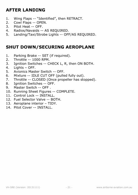
AFTER LANDING
1. Wing Flaps -- “Identified”, then RETRACT.
2. Cowl Flaps -- OPEN.
3. Pitot Heat -- OFF.
4. Radios/Navaids -- AS REQUIRED.
5. Landing/Taxi/Strobe Lights -- OFF/AS REQUIRED.
SHUT DOWN/SECURING AEROPLANE
1. Parking Brake -- SET (if required).
2. Throttle -- 1000 RPM.
3. Ignition Switches -- CHECK L, R, then ON BOTH.
4. Lights – OFF.
5. Avionics Master Switch -- OFF.
6. Mixture -- IDLE CUT OFF (pulled fully out).
7. Throttle -- CLOSED (Once propeller has stopped).
8. Ignition Switches -- OFF.
9. Master Switch -- OFF .
10. Running Sheet Figures -- COMPLETE. 11. Control Lock -- INSTALL. 12. Fuel Selector Valve -- BOTH. 13. Aeroplane interior – TIDY. 14. Pitot Cover -- INSTALL.
VH-SRE (Version: 20131111) - 22 - www.airborne-aviation.com.au
Checklists – Emergency Procedures
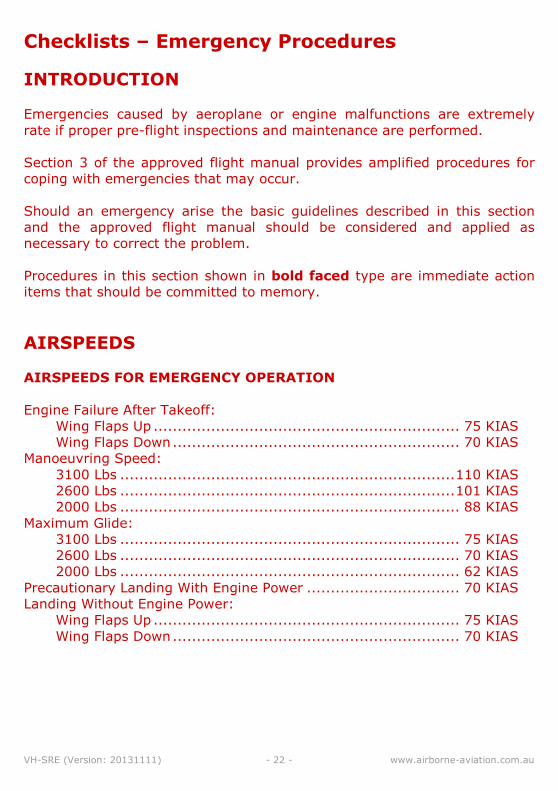
INTRODUCTION
Emergencies caused by aeroplane or engine malfunctions are extremely
rate if proper pre-flight inspections and maintenance are performed.
Section 3 of the approved flight manual provides amplified procedures for
coping with emergencies that may occur.
Should an emergency arise the basic guidelines described in this section
and the approved flight manual should be considered and applied as
necessary to correct the problem.
Procedures in this section shown in bold faced type are immediate action
items that should be committed to memory.
AIRSPEEDS
AIRSPEEDS FOR EMERGENCY OPERATION
Engine Failure After Takeoff:
Wing Flaps Up ................................................................ 75 KIAS
Wing Flaps Down ............................................................ 70 KIAS
Manoeuvring Speed:
3100 Lbs ...................................................................... 110 KIAS
2600 Lbs ...................................................................... 101 KIAS
2000 Lbs ....................................................................... 88 KIAS
Maximum Glide:
3100 Lbs ....................................................................... 75 KIAS
2600 Lbs ....................................................................... 70 KIAS
2000 Lbs ....................................................................... 62 KIAS
Precautionary Landing With Engine Power ................................ 70 KIAS
Landing Without Engine Power:
Wing Flaps Up ................................................................ 75 KIAS
Wing Flaps Down ............................................................ 70 KIAS
VH-SRE (Version: 20131111) - 23 - www.airborne-aviation.com.au
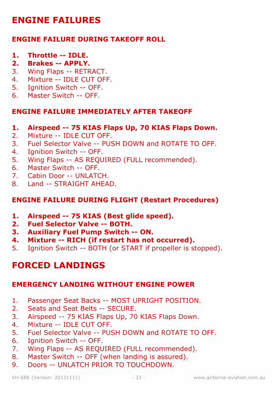
ENGINE FAILURES
ENGINE FAILURE DURING TAKEOFF ROLL
1. Throttle -- IDLE.
2. Brakes -- APPLY.
3. Wing Flaps -- RETRACT.
4. Mixture -- IDLE CUT OFF.
5. Ignition Switch -- OFF.
6. Master Switch -- OFF.
ENGINE FAILURE IMMEDIATELY AFTER TAKEOFF
1. Airspeed -- 75 KIAS Flaps Up, 70 KIAS Flaps Down.
2. Mixture -- IDLE CUT OFF.
3. Fuel Selector Valve -- PUSH DOWN and ROTATE TO OFF.
4. Ignition Switch -- OFF.
5. Wing Flaps -- AS REQUIRED (FULL recommended).
6. Master Switch -- OFF.
7. Cabin Door -- UNLATCH.
8. Land -- STRAIGHT AHEAD.
ENGINE FAILURE DURING FLIGHT (Restart Procedures)
1. Airspeed -- 75 KIAS (Best glide speed).
2. Fuel Selector Valve -- BOTH.
3. Auxiliary Fuel Pump Switch -- ON.
4. Mixture -- RICH (if restart has not occurred).
5. Ignition Switch -- BOTH (or START if propeller is stopped).
FORCED LANDINGS
EMERGENCY LANDING WITHOUT ENGINE POWER
1. Passenger Seat Backs -- MOST UPRIGHT POSITION.
2. Seats and Seat Belts -- SECURE.
3. Airspeed -- 75 KIAS Flaps Up, 70 KIAS Flaps Down.
4. Mixture -- IDLE CUT OFF.
5. Fuel Selector Valve -- PUSH DOWN and ROTATE TO OFF.
6. Ignition Switch -- OFF.
7. Wing Flaps -- AS REQUIRED (FULL recommended).
8. Master Switch -- OFF (when landing is assured).
9. Doors -- UNLATCH PRIOR TO TOUCHDOWN.
VH-SRE (Version: 20131111) - 24 - www.airborne-aviation.com.au
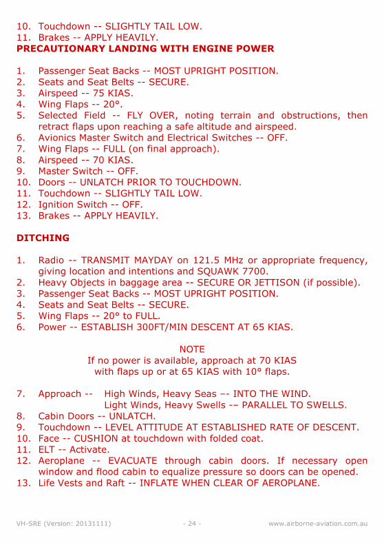
10. Touchdown -- SLIGHTLY TAIL LOW. 11. Brakes -- APPLY HEAVILY. PRECAUTIONARY LANDING WITH ENGINE POWER
1. Passenger Seat Backs -- MOST UPRIGHT POSITION.
2. Seats and Seat Belts -- SECURE.
3. Airspeed -- 75 KIAS.
4. Wing Flaps -- 20°.
5. Selected Field -- FLY OVER, noting terrain and obstructions, then
retract flaps upon reaching a safe altitude and airspeed.
6. Avionics Master Switch and Electrical Switches -- OFF.
7. Wing Flaps -- FULL (on final approach).
8. Airspeed -- 70 KIAS.
9. Master Switch -- OFF.
10. Doors -- UNLATCH PRIOR TO TOUCHDOWN. 11. Touchdown -- SLIGHTLY TAIL LOW. 12. Ignition Switch -- OFF. 13. Brakes -- APPLY HEAVILY.
DITCHING
1. Radio -- TRANSMIT MAYDAY on 121.5 MHz or appropriate frequency,
giving location and intentions and SQUAWK 7700.
2. Heavy Objects in baggage area -- SECURE OR JETTISON (if possible).
3. Passenger Seat Backs -- MOST UPRIGHT POSITION.
4. Seats and Seat Belts -- SECURE.
5. Wing Flaps -- 20° to FULL.
6. Power -- ESTABLISH 300FT/MIN DESCENT AT 65 KIAS.
NOTE
If no power is available, approach at 70 KIAS
with flaps up or at 65 KIAS with 10° flaps.
7. Approach -- High Winds, Heavy Seas –- INTO THE WIND.
Light Winds, Heavy Swells -– PARALLEL TO SWELLS.
8. Cabin Doors -- UNLATCH.
9. Touchdown -- LEVEL ATTITUDE AT ESTABLISHED RATE OF DESCENT.
10. Face -- CUSHION at touchdown with folded coat. 11. ELT -- Activate. 12. Aeroplane -- EVACUATE through cabin doors. If necessary open
window and flood cabin to equalize pressure so doors can be opened.
13. Life Vests and Raft -- INFLATE WHEN CLEAR OF AEROPLANE.
VH-SRE (Version: 20131111) - 25 - www.airborne-aviation.com.au
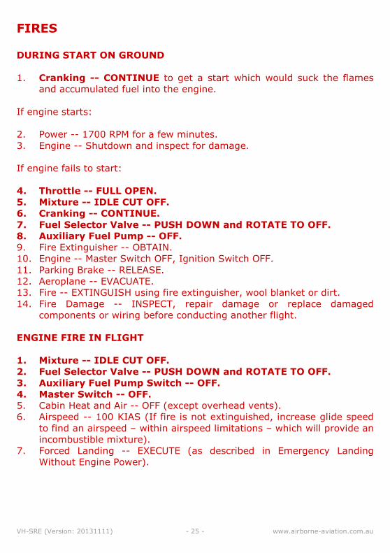
FIRES
DURING START ON GROUND
1. Cranking -- CONTINUE to get a start which would suck the flames
and accumulated fuel into the engine.
If engine starts:
2. Power -- 1700 RPM for a few minutes.
3. Engine -- Shutdown and inspect for damage.
If engine fails to start:
4. Throttle -- FULL OPEN.
5. Mixture -- IDLE CUT OFF.
6. Cranking -- CONTINUE.
7. Fuel Selector Valve -- PUSH DOWN and ROTATE TO OFF.
8. Auxiliary Fuel Pump -- OFF.
9. Fire Extinguisher -- OBTAIN.
10. Engine -- Master Switch OFF, Ignition Switch OFF. 11. Parking Brake -- RELEASE. 12. Aeroplane -- EVACUATE. 13. Fire -- EXTINGUISH using fire extinguisher, wool blanket or dirt. 14. Fire Damage -- INSPECT, repair damage or replace damaged
components or wiring before conducting another flight.
ENGINE FIRE IN FLIGHT
1. Mixture -- IDLE CUT OFF.
2. Fuel Selector Valve -- PUSH DOWN and ROTATE TO OFF.
3. Auxiliary Fuel Pump Switch -- OFF.
4. Master Switch -- OFF.
5. Cabin Heat and Air -- OFF (except overhead vents).
6. Airspeed -- 100 KIAS (If fire is not extinguished, increase glide speed
to find an airspeed – within airspeed limitations – which will provide an
incombustible mixture).
7. Forced Landing -- EXECUTE (as described in Emergency Landing
Without Engine Power).
VH-SRE (Version: 20131111) - 26 - www.airborne-aviation.com.au
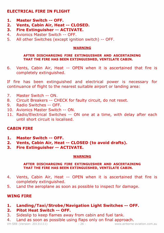
ELECTRICAL FIRE IN FLIGHT
1. Master Switch -- OFF.
2. Vents, Cabin Air, Heat -- CLOSED.
3. Fire Extinguisher -- ACTIVATE.
4. Avionics Master Switch -- OFF.
5. All other Switches (except ignition switch) -- OFF.
WARNING
AFTER DISCHARGING FIRE EXTINGUISHER AND ASCERTAINING THAT THE FIRE HAS BEEN EXTINGUISHED, VENTILATE CABIN.
6. Vents, Cabin Air, Heat -- OPEN when it is ascertained that fire is
completely extinguished.
If fire has been extinguished and electrical power is necessary for
continuance of flight to the nearest suitable airport or landing area:
7. Master Switch -- ON.
8. Circuit Breakers -- CHECK for faulty circuit, do not reset.
9. Radio Switches -- OFF.
10. Avionics Master Switch -- ON. 11. Radio/Electrical Switches -- ON one at a time, with delay after each
until short circuit is localised.
CABIN FIRE
1. Master Switch -- OFF.
2. Vents, Cabin Air, Heat -- CLOSED (to avoid drafts).
3. Fire Extinguisher -- ACTIVATE.
WARNING
AFTER DISCHARGING FIRE EXTINGUISHER AND ASCERTAINING THAT THE FIRE HAS BEEN EXTINGUISHED, VENTILATE CABIN.
4. Vents, Cabin Air, Heat -- OPEN when it is ascertained that fire is
completely extinguished.
5. Land the aeroplane as soon as possible to inspect for damage.
WING FIRE
1. Landing/Taxi/Strobe/Navigation Light Switches -- OFF.
2. Pitot Heat Switch -- OFF.
3. Sideslip to keep flames away from cabin and fuel tank.
4. Land as soon as possible using flaps only on final approach.
VH-SRE (Version: 20131111) - 27 - www.airborne-aviation.com.au
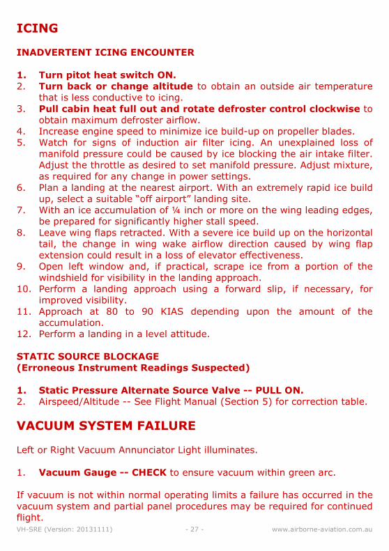
ICING
INADVERTENT ICING ENCOUNTER
1. Turn pitot heat switch ON.
2. Turn back or change altitude to obtain an outside air temperature
that is less conductive to icing.
3. Pull cabin heat full out and rotate defroster control clockwise to
obtain maximum defroster airflow.
4. Increase engine speed to minimize ice build-up on propeller blades.
5. Watch for signs of induction air filter icing. An unexplained loss of
manifold pressure could be caused by ice blocking the air intake filter.
Adjust the throttle as desired to set manifold pressure. Adjust mixture,
as required for any change in power settings.
6. Plan a landing at the nearest airport. With an extremely rapid ice build
up, select a suitable “off airport” landing site.
7. With an ice accumulation of ¼ inch or more on the wing leading edges,
be prepared for significantly higher stall speed.
8. Leave wing flaps retracted. With a severe ice build up on the horizontal
tail, the change in wing wake airflow direction caused by wing flap
extension could result in a loss of elevator effectiveness.
9. Open left window and, if practical, scrape ice from a portion of the
windshield for visibility in the landing approach.
10. Perform a landing approach using a forward slip, if necessary, for improved visibility.
11. Approach at 80 to 90 KIAS depending upon the amount of the accumulation.
12. Perform a landing in a level attitude.
STATIC SOURCE BLOCKAGE
(Erroneous Instrument Readings Suspected)
1. Static Pressure Alternate Source Valve -- PULL ON.
2. Airspeed/Altitude -- See Flight Manual (Section 5) for correction table.
VACUUM SYSTEM FAILURE
Left or Right Vacuum Annunciator Light illuminates.
1. Vacuum Gauge -- CHECK to ensure vacuum within green arc.
If vacuum is not within normal operating limits a failure has occurred in the
vacuum system and partial panel procedures may be required for continued
flight.
VH-SRE (Version: 20131111) - 28 - www.airborne-aviation.com.au
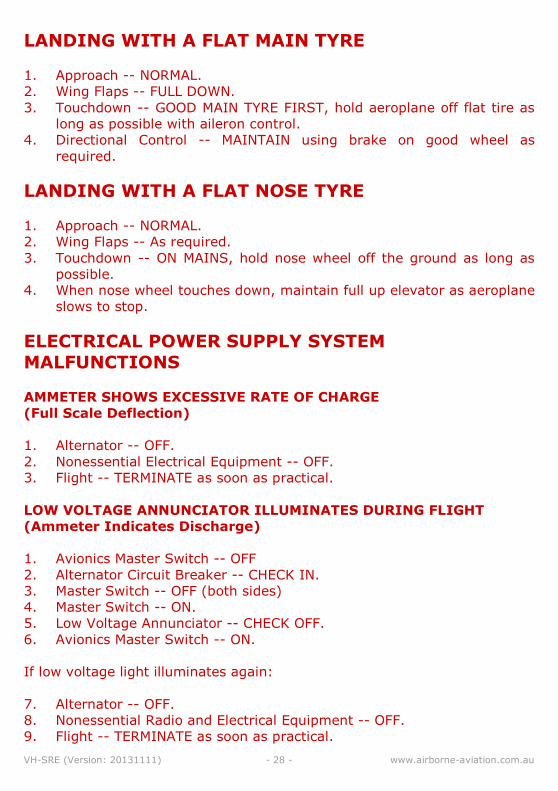
LANDING WITH A FLAT MAIN TYRE
1. Approach -- NORMAL.
2. Wing Flaps -- FULL DOWN.
3. Touchdown -- GOOD MAIN TYRE FIRST, hold aeroplane off flat tire as
long as possible with aileron control.
4. Directional Control -- MAINTAIN using brake on good wheel as
required.
LANDING WITH A FLAT NOSE TYRE
1. Approach -- NORMAL.
2. Wing Flaps -- As required.
3. Touchdown -- ON MAINS, hold nose wheel off the ground as long as
possible.
4. When nose wheel touches down, maintain full up elevator as aeroplane
slows to stop.
ELECTRICAL POWER SUPPLY SYSTEM
MALFUNCTIONS
AMMETER SHOWS EXCESSIVE RATE OF CHARGE
(Full Scale Deflection)
1. Alternator -- OFF.
2. Nonessential Electrical Equipment -- OFF.
3. Flight -- TERMINATE as soon as practical.
LOW VOLTAGE ANNUNCIATOR ILLUMINATES DURING FLIGHT
(Ammeter Indicates Discharge)
1. Avionics Master Switch -- OFF
2. Alternator Circuit Breaker -- CHECK IN.
3. Master Switch -- OFF (both sides)
4. Master Switch -- ON.
5. Low Voltage Annunciator -- CHECK OFF.
6. Avionics Master Switch -- ON.
If low voltage light illuminates again:
7. Alternator -- OFF.
8. Nonessential Radio and Electrical Equipment -- OFF.
9. Flight -- TERMINATE as soon as practical.
VH-SRE (Version: 20131111) - 29 - www.airborne-aviation.com.au
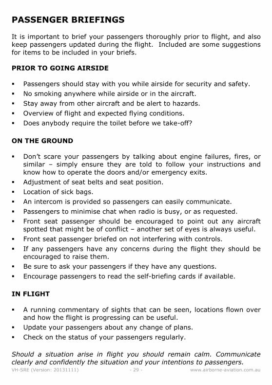
PASSENGER BRIEFINGS
It is important to brief your passengers thoroughly prior to flight, and also
keep passengers updated during the flight. Included are some suggestions
for items to be included in your briefs.
PRIOR TO GOING AIRSIDE
� Passengers should stay with you while airside for security and safety.
� No smoking anywhere while airside or in the aircraft.
� Stay away from other aircraft and be alert to hazards.
� Overview of flight and expected flying conditions.
� Does anybody require the toilet before we take-off?
ON THE GROUND
� Don’t scare your passengers by talking about engine failures, fires, or
similar – simply ensure they are told to follow your instructions and
know how to operate the doors and/or emergency exits.
� Adjustment of seat belts and seat position.
� Location of sick bags.
� An intercom is provided so passengers can easily communicate.
� Passengers to minimise chat when radio is busy, or as requested.
� Front seat passenger should be encouraged to point out any aircraft
spotted that might be of conflict – another set of eyes is always useful.
� Front seat passenger briefed on not interfering with controls.
� If any passengers have any concerns during the flight they should be
encouraged to raise them.
� Be sure to ask your passengers if they have any questions.
� Encourage passengers to read the self-briefing cards if available.
IN FLIGHT
� A running commentary of sights that can be seen, locations flown over
and how the flight is progressing can be useful.
� Update your passengers about any change of plans.
� Check on the status of your passengers regularly.
Should a situation arise in flight you should remain calm. Communicate
clearly and confidently the situation and your intentions to passengers.
VH-SRE (Version: 20131111) - 30 - www.airborne-aviation.com.au
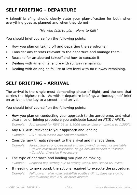
SELF BRIEFING - DEPARTURE
A takeoff briefing should clearly state your plan-of-action for both when
everything goes as planned and when they do not!
“He who fails to plan, plans to fail!”
You should brief yourself on the following points:
� How you plan on taking off and departing the aerodrome.
� Consider any threats relevant to the departure and manage them.
� Reasons for an aborted takeoff and how to execute it.
� Dealing with an engine failure with runway remaining.
� Dealing with an engine failure at low level with no runway remaining.
SELF BRIEFING - ARRIVAL
The arrival is the single most demanding phase of flight, and the one that
carries the highest risk. As with a departure briefing, a thorough self brief
on arrival is the key to a smooth and arrival.
You should brief yourself on the following points:
� How you plan on conducting your approach to the aerodrome, and what
clearance or joining procedure you anticipate based on ATIS / AWIS.
Example: Join upwind for RWY 06 at 1,800ft descending on upwind to 1,300ft.
� Any NOTAMS relevant to your approach and landing.
Example: RWY 10/28 closed due soft wet surface.
� Consider any threats relevant to the arrival and manage them.
Example: Particularly strong crosswind and in-to-wind runway not available.
- Revise crosswind procedure, be go-around minded if unstable. - Consider diversion if necessary.
� The type of approach and landing you plan on making.
Example: Reduced flap setting due to strong winds, final speed 65-75kts.
� If needing to go-around, the actions required to execute the procedure.
Example: Full power, raise nose, establish positive climb, flaps up slowly, communicate with ATC or other aircraft.
VH-SRE (Version: 20131111) - 31 - www.airborne-aviation.com.au
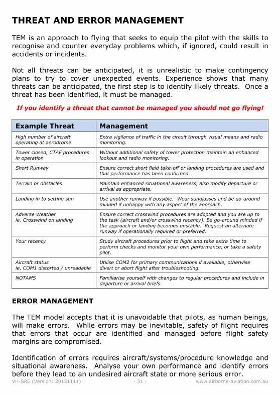
THREAT AND ERROR MANAGEMENT
TEM is an approach to flying that seeks to equip the pilot with the skills to
recognise and counter everyday problems which, if ignored, could result in
accidents or incidents.
Not all threats can be anticipated, it is unrealistic to make contingency
plans to try to cover unexpected events. Experience shows that many
threats can be anticipated, the first step is to identify likely threats. Once a
threat has been identified, it must be managed.
If you identify a threat that cannot be managed you should not go flying!
Example Threat Management
High number of aircraft operating at aerodrome
Extra vigilance of traffic in the circuit through visual means and radio monitoring.
Tower closed, CTAF procedures
in operation
Without additional safety of tower protection maintain an enhanced
lookout and radio monitoring.
Short Runway Ensure correct short field take-off or landing procedures are used and that performance has been confirmed.
Terrain or obstacles Maintain enhanced situational awareness, also modify departure or
arrival as appropriate.
Landing in to setting sun Use another runway if possible. Wear sunglasses and be go-around
minded if unhappy with any aspect of the approach.
Adverse Weather
ie. Crosswind on landing
Ensure correct crosswind procedures are adopted and you are up to
the task (aircraft and/or crosswind recency). Be go-around minded if
the approach or landing becomes unstable. Request an alternate
runway if operationally required or preferred.
Your recency Study aircraft procedures prior to flight and take extra time to
perform checks and monitor your own performance, or take a safety
pilot.
Aircraft status
ie. COM1 distorted / unreadable
Utilise COM2 for primary communications if available, otherwise
divert or abort flight after troubleshooting.
NOTAMS Familiarise yourself with changes to regular procedures and include in
departure or arrival briefs.
ERROR MANAGEMENT
The TEM model accepts that it is unavoidable that pilots, as human beings,
will make errors. While errors may be inevitable, safety of flight requires
that errors that occur are identified and managed before flight safety
margins are compromised.
Identification of errors requires aircraft/systems/procedure knowledge and
situational awareness. Analyse your own performance and identify errors
before they lead to an undesired aircraft state or more serious error.
VH-SRE (Version: 20131111) - 32 - www.airborne-aviation.com.au
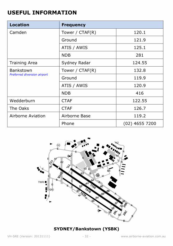
USEFUL INFORMATION
Location Frequency
Camden Tower / CTAF(R) 120.1
Ground 121.9
ATIS / AWIS 125.1
NDB 281
Training Area Sydney Radar 124.55
Bankstown Preferred diversion airport
Tower / CTAF(R) 132.8
Ground 119.9
ATIS / AWIS 120.9
NDB 416
Wedderburn CTAF 122.55
The Oaks CTAF 126.7
Airborne Aviation Airborne Base 119.2
Phone (02) 4655 7200
SYDNEY/Bankstown (YSBK)

VH-SRE (Version: 20131111) - 33 - www.airborne-aviation.com.au
Notes
………………………………………………………………………………………………………………………………………
………………………………………………………………………………………………………………………………………
………………………………………………………………………………………………………………………………………
………………………………………………………………………………………………………………………………………
………………………………………………………………………………………………………………………………………
………………………………………………………………………………………………………………………………………
………………………………………………………………………………………………………………………………………
………………………………………………………………………………………………………………………………………
………………………………………………………………………………………………………………………………………
………………………………………………………………………………………………………………………………………
………………………………………………………………………………………………………………………………………
………………………………………………………………………………………………………………………………………
………………………………………………………………………………………………………………………………………
………………………………………………………………………………………………………………………………………
………………………………………………………………………………………………………………………………………
………………………………………………………………………………………………………………………………………