Embed Size (px)
Citation preview
CESoPSN
Tuan Nguyen-viet
World of Standards
2
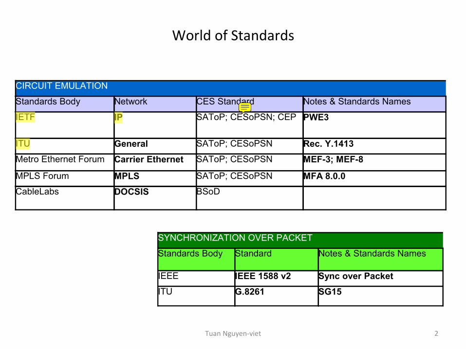
CIRCUIT EMULATION
Standards Body Network CES Standard Notes & Standards Names
IETF IP SAToP; CESoPSN; CEP PWE3
ITU General SAToP; CESoPSN Rec. Y.1413Metro Ethernet Forum Carrier Ethernet SAToP; CESoPSN MEF-3; MEF-8
MPLS Forum MPLS SAToP; CESoPSN MFA 8.0.0CableLabs DOCSIS BSoD
SYNCHRONIZATION OVER PACKET
Standards Body Standard Notes & Standards Names
IEEE IEEE 1588 v2 Sync over PacketITU G.8261 SG15
Tuan Nguyen-viet
Part 1: RFC5086 CESoPSN Background
3Tuan Nguyen-viet
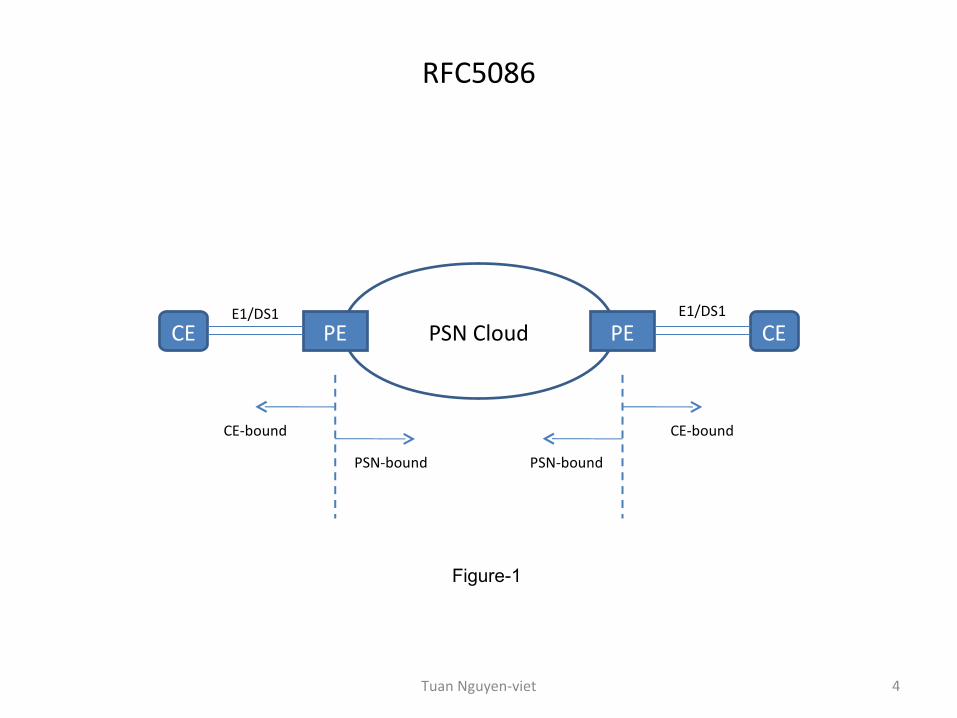
RFC5086
PSN CloudPE PECE CE
PSN-bound
CE-bound
E1/DS1 E1/DS1
PSN-bound
CE-bound
Figure-1
4Tuan Nguyen-viet
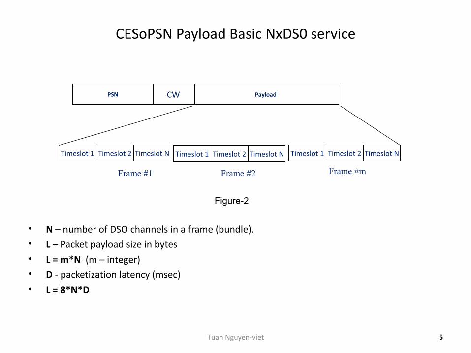
CESoPSN Payload Basic NxDS0 service
• N – number of DSO channels in a frame (bundle).• L – Packet payload size in bytes• L = m*N (m – integer) • D - packetization latency (msec)• L = 8*N*D
Frame #mFrame #1 Frame #2
PayloadCWPSN
Timeslot 1 Timeslot 2 Timeslot N Timeslot 1 Timeslot 2 Timeslot N Timeslot 1 Timeslot 2 Timeslot N
Figure-2
5Tuan Nguyen-viet
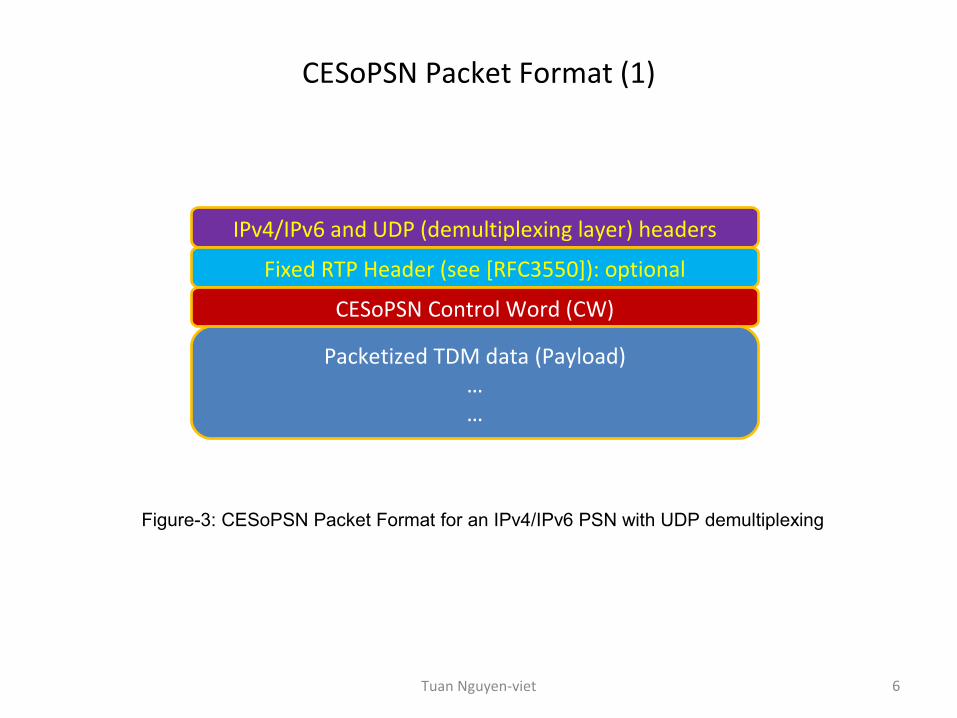
CESoPSN Packet Format (1)
IPv4/IPv6 and UDP (demultiplexing layer) headers
Fixed RTP Header (see [RFC3550]): optional
CESoPSN Control Word (CW)
Packetized TDM data (Payload)……
Figure-3: CESoPSN Packet Format for an IPv4/IPv6 PSN with UDP demultiplexing
6Tuan Nguyen-viet
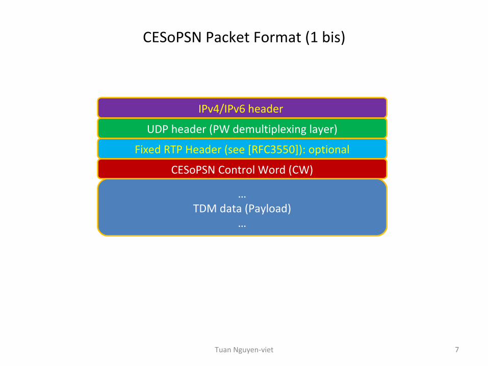
CESoPSN Packet Format (1 bis)
7
UDP header (PW demultiplexing layer)
Fixed RTP Header (see [RFC3550]): optional
CESoPSN Control Word (CW)
…TDM data (Payload)
…
IPv4/IPv6 header
Tuan Nguyen-viet
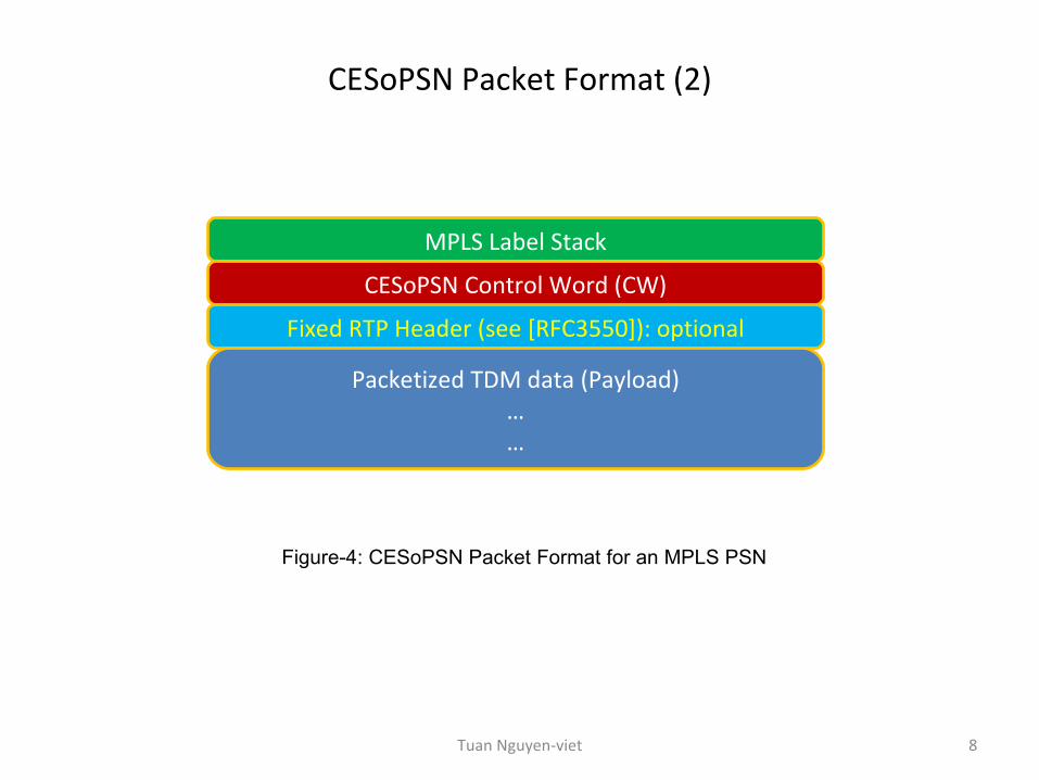
CESoPSN Packet Format (2)
MPLS Label Stack
CESoPSN Control Word (CW)
Fixed RTP Header (see [RFC3550]): optional
Packetized TDM data (Payload)……
Figure-4: CESoPSN Packet Format for an MPLS PSN
8Tuan Nguyen-viet
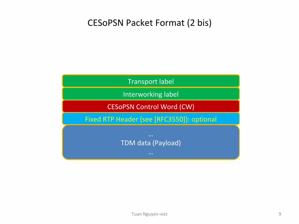
CESoPSN Packet Format (2 bis)
9
Interworking label
CESoPSN Control Word (CW)
Fixed RTP Header (see [RFC3550]): optional
…TDM data (Payload)
…
Transport label
Tuan Nguyen-viet
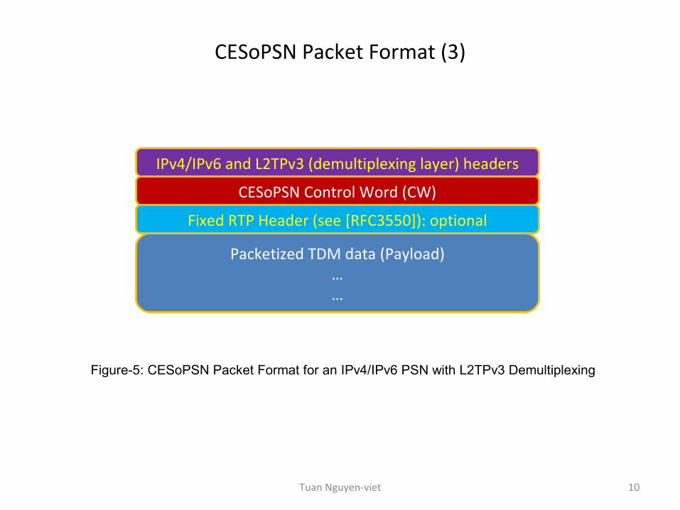
CESoPSN Packet Format (3)
IPv4/IPv6 and L2TPv3 (demultiplexing layer) headers
CESoPSN Control Word (CW)
Fixed RTP Header (see [RFC3550]): optional
Packetized TDM data (Payload)……
Figure-5: CESoPSN Packet Format for an IPv4/IPv6 PSN with L2TPv3 Demultiplexing
10Tuan Nguyen-viet
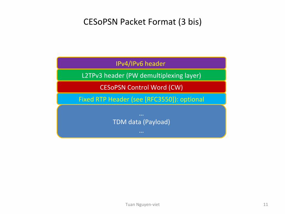
CESoPSN Packet Format (3 bis)
11
L2TPv3 header (PW demultiplexing layer)
Fixed RTP Header (see [RFC3550]): optional
CESoPSN Control Word (CW)
…TDM data (Payload)
…
IPv4/IPv6 header
Tuan Nguyen-viet
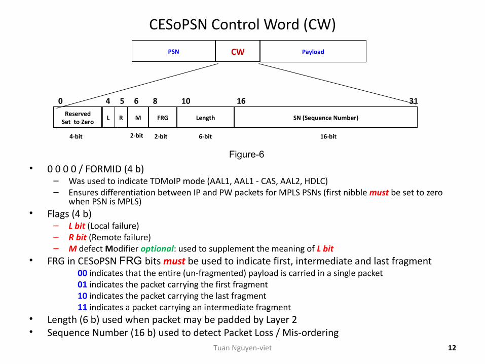
CESoPSN Control Word (CW)
• 0 0 0 0 / FORMID (4 b)– Was used to indicate TDMoIP mode (AAL1, AAL1 - CAS, AAL2, HDLC)– Ensures differentiation between IP and PW packets for MPLS PSNs (first nibble must be set to zero
when PSN is MPLS)• Flags (4 b)
– L bit (Local failure)– R bit (Remote failure)– M defect Modifier optional: used to supplement the meaning of L bit
• FRG in CESoPSN FRG bits must be used to indicate first, intermediate and last fragment 00 indicates that the entire (un-fragmented) payload is carried in a single packet 01 indicates the packet carrying the first fragment
10 indicates the packet carrying the last fragment 11 indicates a packet carrying an intermediate fragment
• Length (6 b) used when packet may be padded by Layer 2• Sequence Number (16 b) used to detect Packet Loss / Mis-ordering
ReservedSet to Zero
L R M FRG Length SN (Sequence Number)
540 6 8 10 16 31
PayloadCWPSN
2-bit 2-bit 6-bit 16-bit4-bit
Figure-6
12Tuan Nguyen-viet
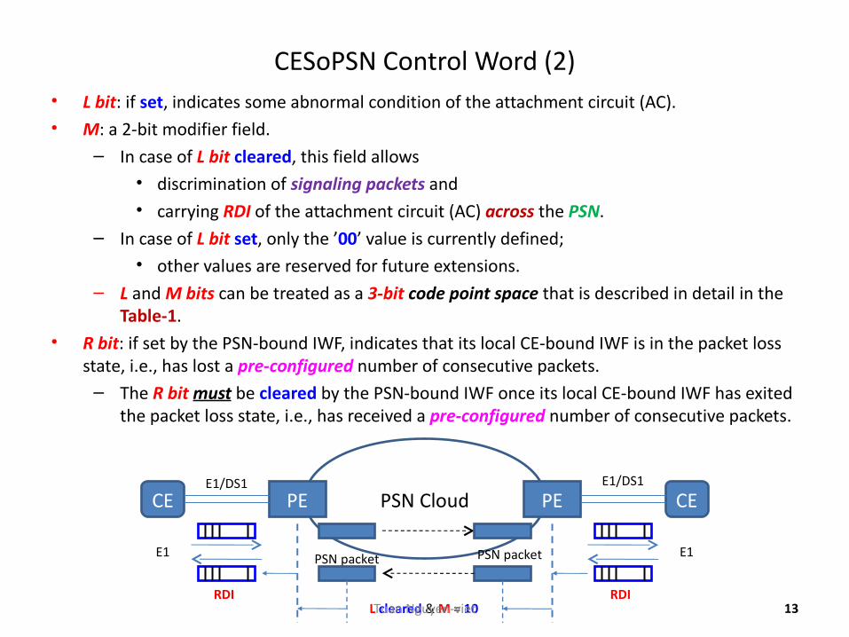
CESoPSN Control Word (2)• L bit: if set, indicates some abnormal condition of the attachment circuit (AC).• M: a 2-bit modifier field.
– In case of L bit cleared, this field allows• discrimination of signaling packets and• carrying RDI of the attachment circuit (AC) across the PSN.
– In case of L bit set, only the ’00’ value is currently defined;• other values are reserved for future extensions.
– L and M bits can be treated as a 3-bit code point space that is described in detail in the Table-1.
• R bit: if set by the PSN-bound IWF, indicates that its local CE-bound IWF is in the packet loss state, i.e., has lost a pre-configured number of consecutive packets.
– The R bit must be cleared by the PSN-bound IWF once its local CE-bound IWF has exited the packet loss state, i.e., has received a pre-configured number of consecutive packets.
13
PSN CloudPE PECE CE
PSN packetE1
E1/DS1 E1/DS1
L cleared & M = 10RDI
PSN packet E1
RDITuan Nguyen-viet
CESoPSN Control Word (3)
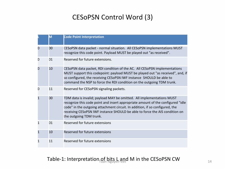
L M Code Point Interpretation
0 00 CESoPSN data packet - normal situation. All CESoPSN implementations MUST recognize this code point. Payload MUST be played out "as received".
0 01 Reserved for future extensions.
0 10 CESoPSN data packet, RDI condition of the AC. All CESoPSN implementations MUST support this codepoint: payload MUST be played out "as received", and, if so configured, the receiving CESoPSN IWF instance SHOULD be able to command the NSP to force the RDI condition on the outgoing TDM trunk.
0 11 Reserved for CESoPSN signaling packets.
1 00 TDM data is invalid; payload MAY be omitted. All implementations MUST recognize this code point and insert appropriate amount of the configured "idle code" in the outgoing attachment circuit. In addition, if so configured, the receiving CESoPSN IWF instance SHOULD be able to force the AIS condition on the outgoing TDM trunk.
1 01 Reserved for future extensions
1 10 Reserved for future extensions
1 11 Reserved for future extensions
Table-1: Interpretation of bits L and M in the CESoPSN CW 14Tuan Nguyen-viet
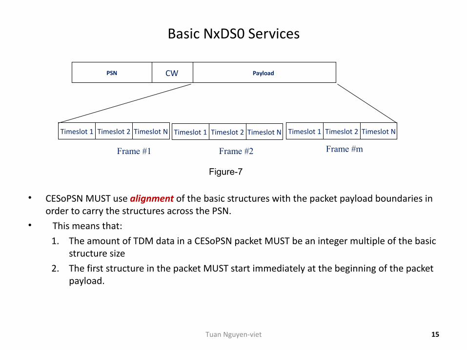
Basic NxDS0 Services
• CESoPSN MUST use alignment of the basic structures with the packet payload boundaries in order to carry the structures across the PSN.
• This means that:
1. The amount of TDM data in a CESoPSN packet MUST be an integer multiple of the basic structure size
2. The first structure in the packet MUST start immediately at the beginning of the packet payload.
Frame #mFrame #1 Frame #2
PayloadCWPSN
Timeslot 1 Timeslot 2 Timeslot N Timeslot 1 Timeslot 2 Timeslot N Timeslot 1 Timeslot 2 Timeslot N
Figure-7
15Tuan Nguyen-viet
Basic NxDS0 Services (2)
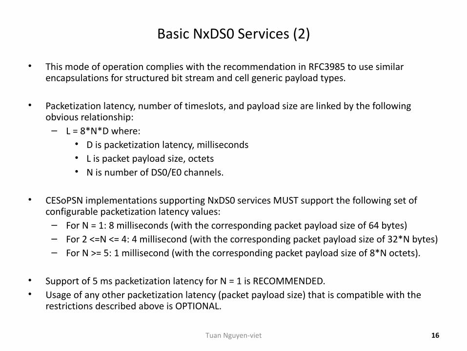
• This mode of operation complies with the recommendation in RFC3985 to use similar encapsulations for structured bit stream and cell generic payload types.
• Packetization latency, number of timeslots, and payload size are linked by the following obvious relationship:
– L = 8*N*D where:• D is packetization latency, milliseconds• L is packet payload size, octets• N is number of DS0/E0 channels.
• CESoPSN implementations supporting NxDS0 services MUST support the following set of configurable packetization latency values:
– For N = 1: 8 milliseconds (with the corresponding packet payload size of 64 bytes)– For 2 <=N <= 4: 4 millisecond (with the corresponding packet payload size of 32*N bytes)– For N >= 5: 1 millisecond (with the corresponding packet payload size of 8*N octets).
• Support of 5 ms packetization latency for N = 1 is RECOMMENDED.• Usage of any other packetization latency (packet payload size) that is compatible with the
restrictions described above is OPTIONAL.
16Tuan Nguyen-viet
Extending Basic NxDS0 Services with CE Application Signaling
• Implementations that have chosen to extend the basic NxDS0 service to support CE application state signaling carry-encoded CE application state signals in separate signaling packets.
• Signaling packets SHOULD be carried in a separate dedicated PW.– However, implementations MAY carry them in the same PW as the TDM data packets for
the basic NxDS0 service.
• The methods of "pairing“ the PWs carrying TDM data and signaling packets for the same extended NxDS0 service are out of scope of RFC5086.
17Tuan Nguyen-viet
Extending Basic NxDS0 Services with CE Application Signaling (2)
• Regardless of the way signaling packets are carried across the PSN, the following rules apply:– The CESoPSN signaling packets MUST:
• a) Use their own sequence numbers (SN) in the CW• b) Set the Flags in the CW like following:
– i) L = 0– ii) M = ’11’– iii) R = 0
– If an RTP header is used in the data packets, it MUST be also used in the signaling packets with the following restrictions:
• a) An additional RTP payload type (from the range of dynamically allocated types) MUST be allocated for the signaling packets.
• b) In addition, the signaling packets MUST use their own SSRC value.
18Tuan Nguyen-viet
Extending Basic NxDS0 Services with CE Application Signaling (3)
• Encoding of CE application state for telephony applications using CAS follows the RFC2833, – which has since been obsolete by the RFC4733 and the RFC4734, but they do not affect
the relevant text.• Encoding of CE application state for telephony application using CCS will be considered in a
separate document.
19Tuan Nguyen-viet
Extending Basic NxDS0 Services with CE Application Signaling (4)
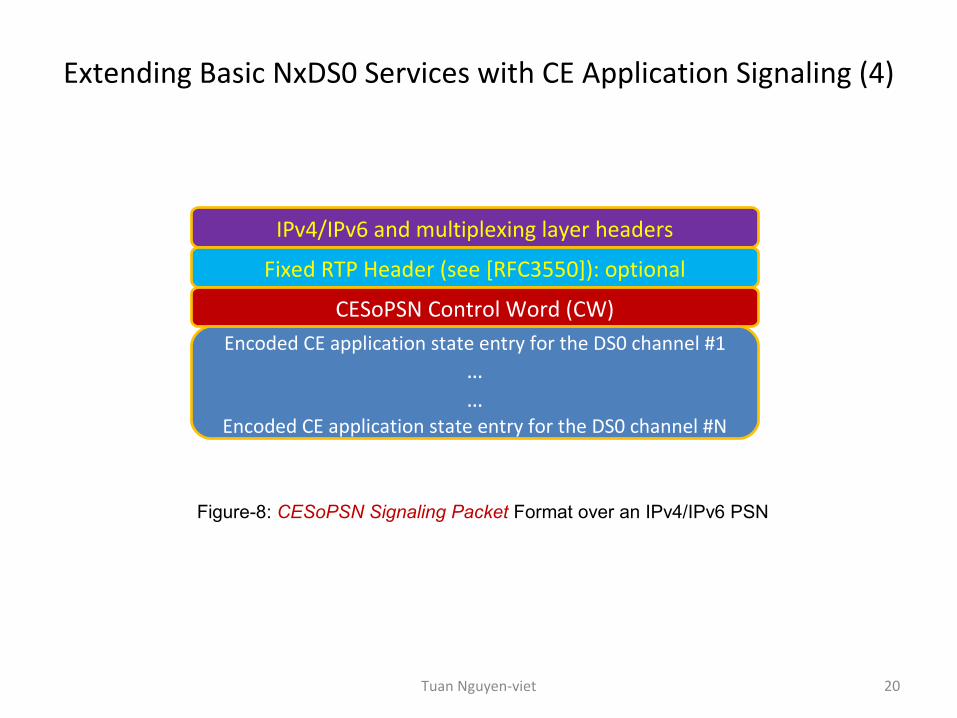
IPv4/IPv6 and multiplexing layer headers
Fixed RTP Header (see [RFC3550]): optional
CESoPSN Control Word (CW)Encoded CE application state entry for the DS0 channel #1
……
Encoded CE application state entry for the DS0 channel #N
Figure-8: CESoPSN Signaling Packet Format over an IPv4/IPv6 PSN
20Tuan Nguyen-viet
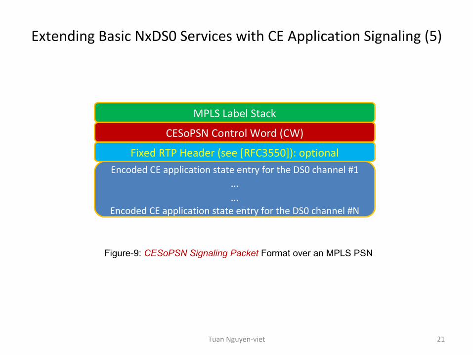
Extending Basic NxDS0 Services with CE Application Signaling (5)
MPLS Label Stack
CESoPSN Control Word (CW)
Fixed RTP Header (see [RFC3550]): optionalEncoded CE application state entry for the DS0 channel #1
……
Encoded CE application state entry for the DS0 channel #N
Figure-9: CESoPSN Signaling Packet Format over an MPLS PSN
21Tuan Nguyen-viet
Trunk-specific NxDS0 services with CAS
• The structure preserved by CESoPSN for this group of services is– the trunk multi-frame sub-divided into the trunk frames, and– signaling information is carried appended to the TDM data using the signaling
substructures defined in [ATM-CES].• These substructures comprise N consecutive nibbles, so that
– the i-th nibble carries CAS bits for the i-th DS0 channel, and– are padded with a dummy nibble for odd values of N.
• CESoPSN implementations supporting trunk-specific NxDS0 services with CAS must not carry more TDM data per packet than is contained in a single trunk multi-frame.
22Tuan Nguyen-viet
Trunk-specific NxDS0 services with CAS (2)
• All CESoPSN implementations supporting trunk-specific NxDS0 with CAS must support the default mode,
– where a single CESoPSN packet carries exactly the amount of TDM data• contained in exactly one trunk multi-frame and• appended with the signaling sub-structure.
• The TDM data is aligned with the packet payload. In this case:– Packetization latency is:
• 2 milliseconds for E1 NxDS0• 3 milliseconds for T1 NxDS0
– The packet payload size is:• 16*N + floor[(N+1)/2] for E1-NxDS0• 24*N + floor[(N+1)/2] for T1/ESF-NxDS0 and T1/SF- NxDS0
– The packet payload format coincides with the multi-frame structure described in [ATM-CES]
• Note: floor function -> [x] = n if and only if n ≤ x < n + 1
23Tuan Nguyen-viet
Trunk-specific NxDS0 services with CAS (3)
• In order to provide lower packetization latency, CESoPSN implementations for trunk-specific NxDS0 with CAS should support fragmentation of multi-frame structures between multiple CESoPSN packets.
• In this case:– The FRG bits (in CW) must be used to indicate first, intermediate, and last fragment of a
multi-frame as described in the RFC4623.– The amount of the TDM data per CESoPSN packet must be constant.– Each multi-frame fragment must comprise an integer multiple of the trunk frames.– The signaling substructure must be appended to the last fragment of each multi-frame.
24Tuan Nguyen-viet
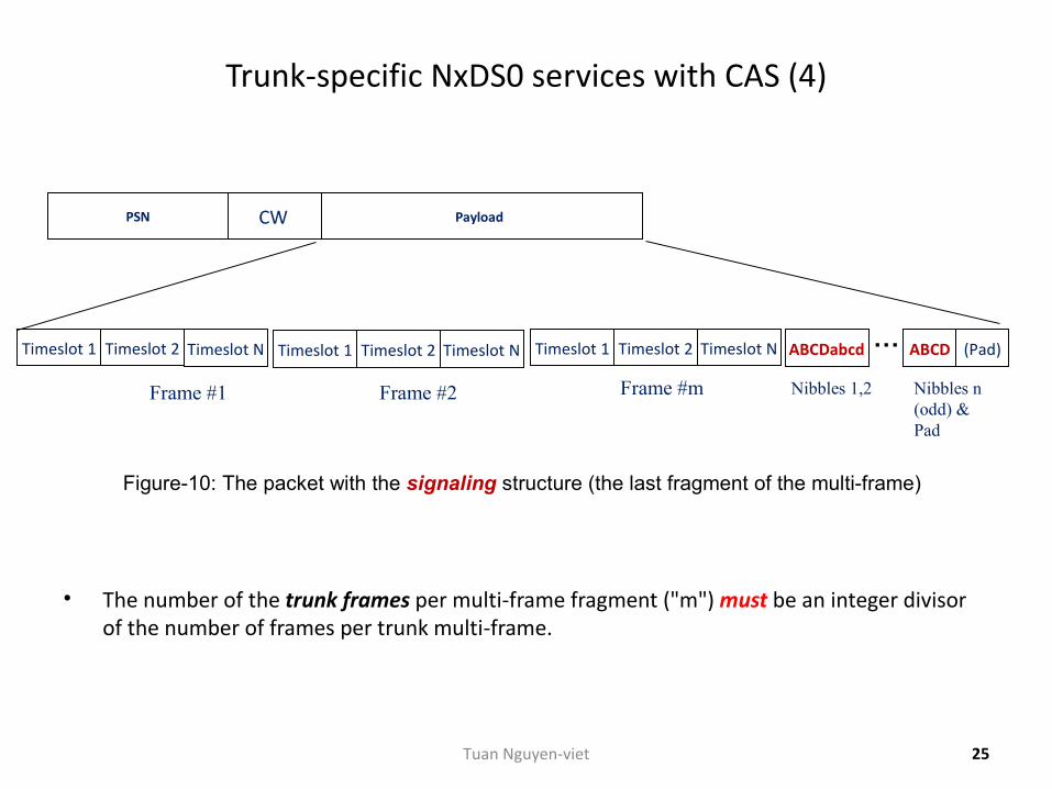
Trunk-specific NxDS0 services with CAS (4)
• The number of the trunk frames per multi-frame fragment ("m") must be an integer divisor of the number of frames per trunk multi-frame.
Frame #mFrame #1 Frame #2
PayloadCWPSN
Timeslot 1 Timeslot 2 Timeslot N Timeslot 1 Timeslot 2 Timeslot N Timeslot 1 Timeslot 2 Timeslot N ABCDabcd ABCD… (Pad)
Nibbles 1,2 Nibbles n (odd) & Pad
Figure-10: The packet with the signaling structure (the last fragment of the multi-frame)
25Tuan Nguyen-viet
Trunk-specific NxDS0 services with CAS (5)
• Notes:– In case of T1-NxDS0 with CAS,
• the signaling bits are carried in the TDM data, as well as in the signaling substructure (see the Figure-10).
• However, the receiver must use the CAS bits as carried in the signaling substructures.
– In case of trunk-specific NxDS0 with CAS originating in a T1-SF trunk (see the next slide),• each nibble of the signaling substructure contains A and B bits from two
consecutive trunk multi-frames as described in the ATM-CES.
26Tuan Nguyen-viet
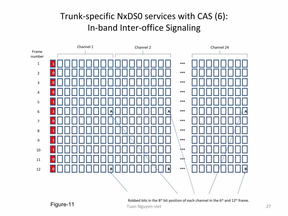
Trunk-specific NxDS0 services with CAS (6):In-band Inter-office Signaling
1 …
Channel 1 Channel 2 Channel 24
0 …
0 …
0 …
1 …
1 A A … A
0 …
1 …
1 …
1 …
0 …
0 B B … B
1
2
3
4
5
6
7
8
9
10
11
12
Frame number
Robbed bits in the 8th bit position of each channel in the 6th and 12th frame.Figure-11 27Tuan Nguyen-viet
Part 2: RFC5086 CESoPSN Operation
28Tuan Nguyen-viet
Common Considerations
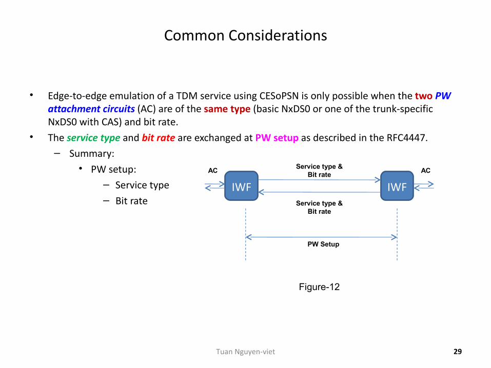
• Edge-to-edge emulation of a TDM service using CESoPSN is only possible when the two PW attachment circuits (AC) are of the same type (basic NxDS0 or one of the trunk-specific NxDS0 with CAS) and bit rate.
• The service type and bit rate are exchanged at PW setup as described in the RFC4447.– Summary:
• PW setup:– Service type– Bit rate
IWF IWF
ACAC
Service type & Bit rate
Service type & Bit rate
PW Setup
Figure-12
29Tuan Nguyen-viet
IWF Operation: PSN-bound Direction
• Once the PW is set up, the PSN-bound CESoPSN IWF operates as follows:
– TDM data is packetized using the configured number of payload bytes per packet.
– Sequence numbers (SN), flags, and timestamps (if the RTP header is used) are inserted in the CESoPSN headers and,
• for trunk-specific NxDS0 with CAS,– signaling substructures are appended to the packets carrying the last
fragment of a multi-frame.
– CESoPSN, multiplexing layer, and PSN headers are pre-pended to the packetized service data.
• • The resulting packets are transmitted over the PSN.
30Tuan Nguyen-viet
IWF Operation: CE-bound Direction
• The CE-bound CESoPSN IWF should include a jitter buffer – where payload of the received CESoPSN packets is stored prior to play-out to the local
TDM attachment circuit (AC).
• The size of this buffer should be locally configurable to allow accommodation to the PSN-specific packet delay variation (PDV).
• The CE-bound CESoPSN IWF must detect lost and mis-ordered packets.
– It should use the sequence number (SN) in the control word (CW) for these purposes but,
• if the RTP header is used, the RTP sequence number (SN) may be used instead.
– The CE-bound CESoPSN IWF may re-order mis-ordered packets.• Mis-ordered packets that cannot be re-ordered must be discarded and treated as
lost.
31Tuan Nguyen-viet
IWF Operation: CE-bound Direction (2)
• The payload of the received CESoPSN data packets marked with the L bit (in CW) set should be replaced by the equivalent amount of some locally configured "idle" bit pattern even if it has not been omitted.
• In addition, the CE-bound CESoPSN IWF will be locally configured to command its local Native Service Processing (NSP) block to perform one of the following actions:
– None (must be supported by all the implementations)
– Transmit the AIS pattern towards the local CE on the E1 or T1 trunk carrying the local attachment circuit (AC)
• (support of this action is recommended)
– Send the "Channel Idle" signal to the local CE for all the DS0 channels comprising the local attachment circuit (AC)
• (support of this action is optional).
32Tuan Nguyen-viet
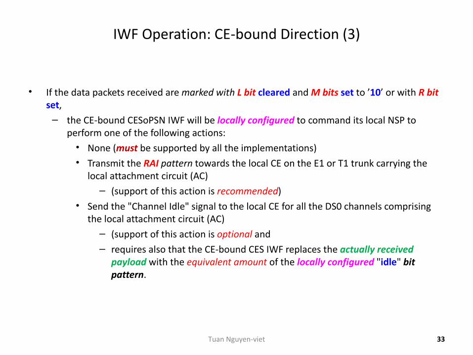
IWF Operation: CE-bound Direction (3)
• If the data packets received are marked with L bit cleared and M bits set to ’10’ or with R bit set,
– the CE-bound CESoPSN IWF will be locally configured to command its local NSP to perform one of the following actions:
• None (must be supported by all the implementations)• Transmit the RAI pattern towards the local CE on the E1 or T1 trunk carrying the
local attachment circuit (AC)– (support of this action is recommended)
• Send the "Channel Idle" signal to the local CE for all the DS0 channels comprising the local attachment circuit (AC)
– (support of this action is optional and– requires also that the CE-bound CES IWF replaces the actually received
payload with the equivalent amount of the locally configured "idle" bit pattern.
33Tuan Nguyen-viet
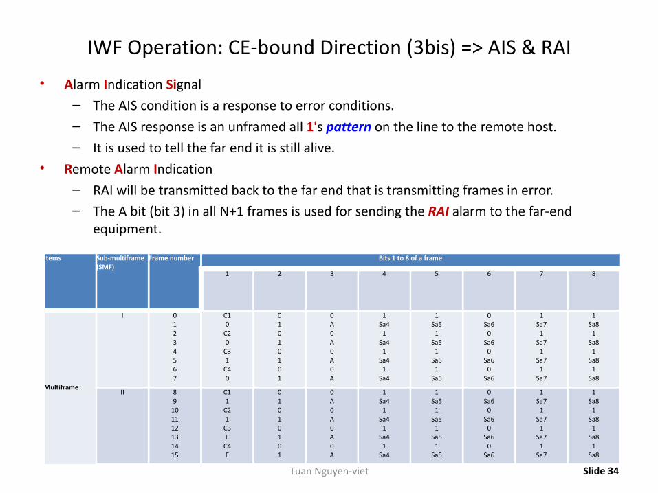
IWF Operation: CE-bound Direction (3bis) => AIS & RAI
• Alarm Indication Signal– The AIS condition is a response to error conditions.– The AIS response is an unframed all 1's pattern on the line to the remote host.– It is used to tell the far end it is still alive.
• Remote Alarm Indication– RAI will be transmitted back to the far end that is transmitting frames in error.– The A bit (bit 3) in all N+1 frames is used for sending the RAI alarm to the far-end
equipment.
Slide 34
Items Sub-multiframe (SMF)
Frame number Bits 1 to 8 of a frame
1 2 3 4 5 6 7 8
Multiframe
I 01234567
C10
C20
C31
C40
01010101
0A0A0A0A
1Sa4
1Sa4
1Sa4
1Sa4
1Sa5
1Sa5
1Sa5
1Sa5
0Sa6
0Sa6
0Sa6
0Sa6
1Sa7
1Sa7
1Sa7
1Sa7
1Sa8
1Sa8
1Sa8
1Sa8
II 89
101112131415
C11
C21
C3E
C4E
01010101
0A0A0A0A
1Sa4
1Sa4
1Sa4
1Sa4
1Sa5
1Sa5
1Sa5
1Sa5
0Sa6
0Sa6
0Sa6
0Sa6
1Sa7
1Sa7
1Sa7
1Sa7
1Sa8
1Sa8
1Sa8
1Sa8
Tuan Nguyen-viet
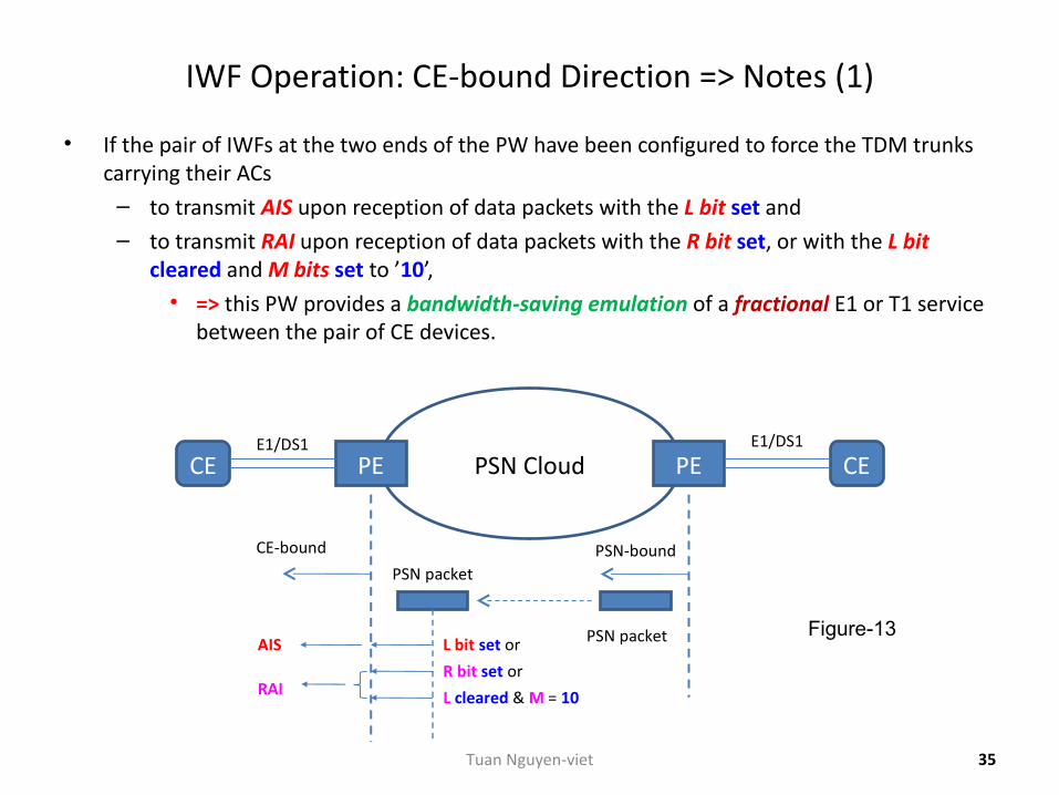
IWF Operation: CE-bound Direction => Notes (1)
• If the pair of IWFs at the two ends of the PW have been configured to force the TDM trunks carrying their ACs
– to transmit AIS upon reception of data packets with the L bit set and– to transmit RAI upon reception of data packets with the R bit set, or with the L bit
cleared and M bits set to ’10’,• => this PW provides a bandwidth-saving emulation of a fractional E1 or T1 service
between the pair of CE devices.
Figure-13
PSN CloudPE PECE CE
PSN packet
CE-bound
E1/DS1 E1/DS1
PSN-bound
L bit set or
R bit set or
L cleared & M = 10
AIS
RAI
PSN packet
35Tuan Nguyen-viet
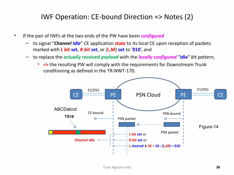
IWF Operation: CE-bound Direction => Notes (2)
• If the pair of IWFs at the two ends of the PW have been configured – to signal "Channel Idle" CE application state to its local CE upon reception of packets
marked with L bit set, R bit set, or (L,M) set to ’010’, and– to replace the actually received payload with the locally configured "idle" bit pattern,
• => the resulting PW will comply with the requirements for Downstream Trunk conditioning as defined in the TR-NWT-170.
Figure-14
36
PSN CloudPE PECE CE
PSN packet
CE-bound
E1/DS1 E1/DS1
PSN-bound
L bit set or
R bit set or
L cleared & M = 10 : (L,M) = 010
Channel Idle
PSN packet
TS16
ABCDabcd
Tuan Nguyen-viet
IWF Operation: CE-bound Direction => Notes (3)
• Usage of bits R, L, and M (in CW) described above– => additionally provides the tools for "single-ended" management of the CESoPSN
pseudowires with ability to distinguish between the problems in the PSN and in the TDM attachment circuits (ACs).
37Tuan Nguyen-viet
IWF Operation: CE-bound Direction => Extra
• The payload of each lost CESoPSN data packet must be replaced with the equivalent amount of the replacement data.
• The contents of the replacement data are implementation-specific and may be locally configurable.
• By default, all CESoPSN implementations must support generation of the locally configurable "idle" pattern as the replacement data.
• Before a PW has been set up and after a PW has been torn down,– the IWF must play out the locally configurable "idle" pattern to its TDM attachment
circuit (AC).
38Tuan Nguyen-viet
IWF Operation: CE-bound Direction => Extra (2)
• Once the PW has been set up,– the CE-bound IWF begins to
• receive CESoPSN packets and to store their payload in the jitter buffer, but• continues to play out the locally configurable "idle" pattern to its TDM attachment
circuit (AC).
• This intermediate state persists– until a pre-configured amount of TDM data (usually half of the jitter buffer) has been
received in consecutive CESoPSN packets, or– until a pre-configured intermediate state timer expires.
39Tuan Nguyen-viet
IWF Operation: CE-bound Direction => Extra (3)
• Once the pre-configured amount of the TDM data has been received,
– the CE-bound CESoPSN IWF enters its normal operation state,• where it continues to
– receive CESoPSN packets and store their payload in the jitter buffer– while playing out the contents of the jitter buffer in accordance with the
required clock.
– In this state, the CE-bound IWF• performs clock recovery,• may monitor PW defects, and• may collect PW performance-monitoring (PM) data.
40Tuan Nguyen-viet
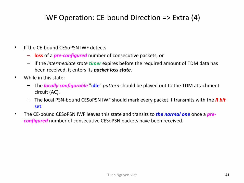
IWF Operation: CE-bound Direction => Extra (4)
• If the CE-bound CESoPSN IWF detects– loss of a pre-configured number of consecutive packets, or– if the intermediate state timer expires before the required amount of TDM data has
been received, it enters its packet loss state.• While in this state:
– The locally configurable "idle" pattern should be played out to the TDM attachment circuit (AC).
– The local PSN-bound CESoPSN IWF should mark every packet it transmits with the R bit set.
• The CE-bound CESoPSN IWF leaves this state and transits to the normal one once a pre-configured number of consecutive CESoPSN packets have been received.
41Tuan Nguyen-viet
Part 3: RFC5086 CESoPSN Defects
42Tuan Nguyen-viet
Defect Detection: Overview
• In addition to the packet loss state of the CE-bound CESoPSN IWF defined above, it may detect the following defects:
– Stray packets– Malformed packets– Excessive packet loss rate– Buffer overrun– Remote packet loss.
43Tuan Nguyen-viet
Defect Detection (2)
• Corresponding to each defect is a defect state of the IWF,– a detection criterion that triggers transition from the normal operation state to the
appropriate defect state, and– an alarm that may be reported to the management system and, thereafter, cleared.
• Alarms are only reported when the defect state persists for a pre-configured amount of time (typically 2.5 seconds) and
– must be cleared after the corresponding defect is undetected for a second pre-configured amount of time (typically 10 seconds).
• The trigger and release times for the various alarms may be independent.
44Tuan Nguyen-viet
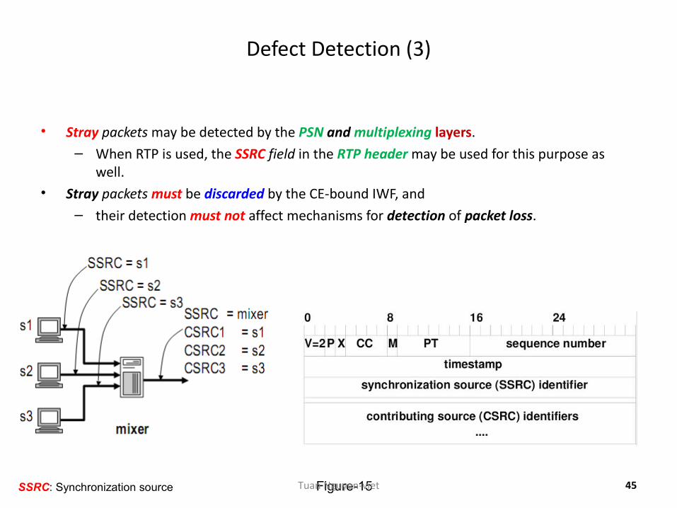
Defect Detection (3)
• Stray packets may be detected by the PSN and multiplexing layers.– When RTP is used, the SSRC field in the RTP header may be used for this purpose as
well.• Stray packets must be discarded by the CE-bound IWF, and
– their detection must not affect mechanisms for detection of packet loss.
SSRC: Synchronization source 45Figure-15Tuan Nguyen-viet
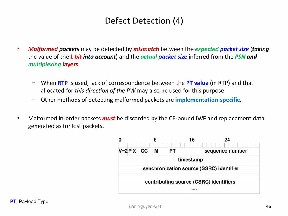
Defect Detection (4)
• Malformed packets may be detected by mismatch between the expected packet size (taking the value of the L bit into account) and the actual packet size inferred from the PSN and multiplexing layers.
– When RTP is used, lack of correspondence between the PT value (in RTP) and that allocated for this direction of the PW may also be used for this purpose.
– Other methods of detecting malformed packets are implementation-specific.
• Malformed in-order packets must be discarded by the CE-bound IWF and replacement data generated as for lost packets.
46PT: Payload Type
Tuan Nguyen-viet
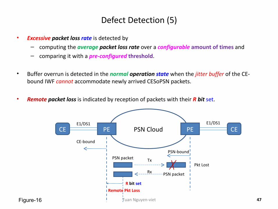
Defect Detection (5)
• Excessive packet loss rate is detected by– computing the average packet loss rate over a configurable amount of times and– comparing it with a pre-configured threshold.
• Buffer overrun is detected in the normal operation state when the jitter buffer of the CE-bound IWF cannot accommodate newly arrived CESoPSN packets.
• Remote packet loss is indicated by reception of packets with their R bit set.
47
PSN CloudPE PECE CE
PSN packet
CE-bound
E1/DS1 E1/DS1
PSN-bound
R bit set
Remote Pkt Loss
PSN packet
Tx
Rx
Pkt Lost
Figure-16 Tuan Nguyen-viet
Part 4: RFC5086 CESoPSN PW Performance Monitoring (PM)
48Tuan Nguyen-viet
PM Usage
• Performance monitoring (PM) parameters are routinely collected for TDM services and provide an important maintenance mechanism in TDM networks.
• Ability to collect compatible PM parameters for CESoPSN PWs enhances their maintenance capabilities.
• Collection of the CESoPSN PW performance monitoring parameters is optional and,– if implemented, is only performed after the CE-bound IWF has exited its intermediate
state.
Slide 49Tuan Nguyen-viet
PM Usage (2)
• CESoPSN defines error events, errored blocks, and defects as follows:
– A CESoPSN error event is defined as insertion of a single replacement packet into the jitter buffer
• (replacement of payload of CESoPSN packets with the L bit set is not considered as insertion of a replacement packet).
– A CESoPSN errored data block is defined as a block of data played out to the TDM attachment circuit (AC) and of size defined in accordance with the ITU-T G.826 rules for the corresponding TDM service that has experienced at least one CESoPSN error event.
– A CESoPSN defect is defined as the packet loss state of the CE-bound CESoPSN IWF.
• The CESoPSN PW PM parameters (Errored, Severely Errored, and Unavailable Seconds) are derived from these definitions, in accordance with the ITU-T G.826.
Slide 50Tuan Nguyen-viet
Part 5: ITU-T Y.1413 CESoPSN
51Tuan Nguyen-viet
Overview
• The ability to transport the following structured TDM types: – 1) DS1 as defined in ITU-T G.704 (N = 24); – 2) Fractional DS1 carrying N timeslots with N from 1 to 23 as defined in ANSI T1.107; – 3) E1 as defined in ITU-T G.704; (N = 30) – 4) Fractional E1 carrying N timeslots with N from 1 to 30 as defined in ITU-T G.704;– 5) DS2 as defined in ITU-T G.704;– 6) Multiple synchronous DS0s.
• The ability to transport the structured TDM types of items 1, 2, 3, 4, 5 with CAS signaling, as defined in ANSI T1.107 and ITU-T G.704.
Slide 52Tuan Nguyen-viet
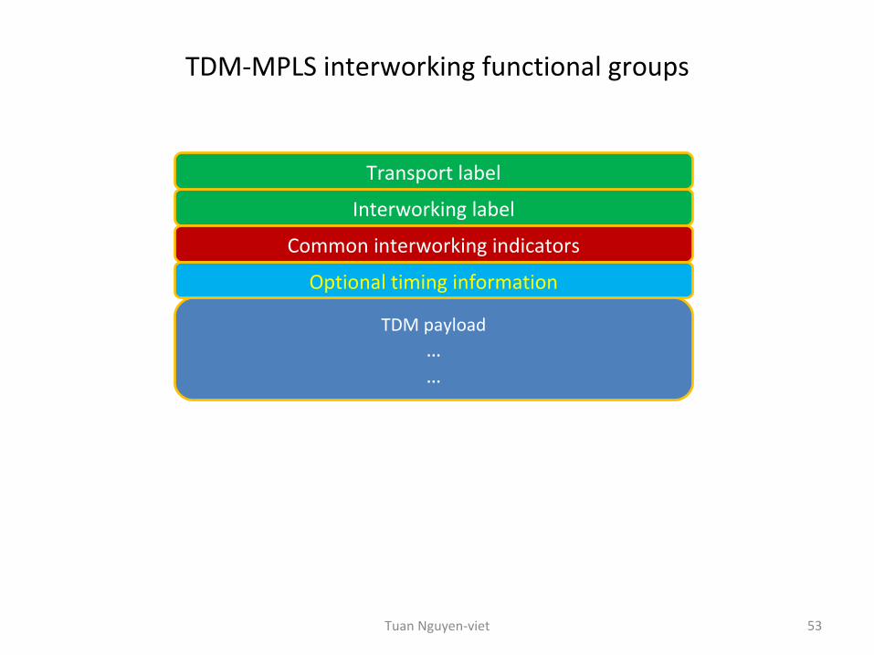
TDM-MPLS interworking functional groups
53
Interworking label
Common interworking indicators
Optional timing information
TDM payload……
Transport label
Tuan Nguyen-viet
Transport label
• Since LSPs are unidirectional while the TDM is inherently bidirectional,– the association of two transport LSPs in opposite directions will be required.– The LSPs may have different label values.
• The 4-octet (32-bit) transport label identifies a LSP used to transport traffic between two IWFs.
• The transport label is a standard MPLS shim header that is processed at each LSR (Label Switch Router).
• The S bit is cleared for this label, indicating that this is not the bottom of the label stack.
• Note:– The setting of the EXP (3-bit CoS) and TTL fields of the transport label is outside the
scope of this Y.1413 Recommendation.
Slide 54Tuan Nguyen-viet
Interworking label
• Since LSPs are unidirectional while the TDM is inherently bidirectional,– the association of two interworking LSPs in opposite directions will be required.– The LSPs may have different label values.
• The interworking function (IWF) maintains context information that associates TDM connections with the interworking LSP.
• The 4-octet (32-bit) interworking label uniquely identifies one interworking LSP carried inside a transport LSP.
– More than one interworking LSP may be supported by one transport LSP. • The interworking label is a standard MPLS shim header, with its S bit set, to indicate the
bottom of the label stack.• Since TDM-MPLS interworking is a strict point-to-point (P2P) application,
– the TTL value should be set to 2.
– Note: The setting of the EXP field of the interworking label is for further study.
Slide 55Tuan Nguyen-viet
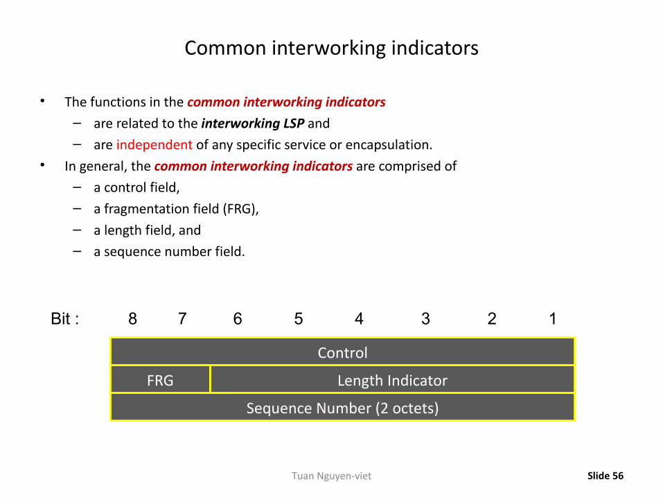
Common interworking indicators
• The functions in the common interworking indicators – are related to the interworking LSP and– are independent of any specific service or encapsulation.
• In general, the common interworking indicators are comprised of– a control field,– a fragmentation field (FRG),– a length field, and– a sequence number field.
Slide 56
Control
FRG Length Indicator
Sequence Number (2 octets)
12345678Bit :
Tuan Nguyen-viet
Control field
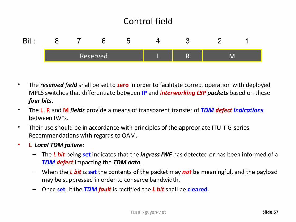
• The reserved field shall be set to zero in order to facilitate correct operation with deployed MPLS switches that differentiate between IP and interworking LSP packets based on these four bits.
• The L, R and M fields provide a means of transparent transfer of TDM defect indications between IWFs.
• Their use should be in accordance with principles of the appropriate ITU-T G-series Recommendations with regards to OAM.
• L Local TDM failure:– The L bit being set indicates that the ingress IWF has detected or has been informed of a
TDM defect impacting the TDM data.– When the L bit is set the contents of the packet may not be meaningful, and the payload
may be suppressed in order to conserve bandwidth. – Once set, if the TDM fault is rectified the L bit shall be cleared.
Slide 57
Reserved L R M
12345678Bit :
Tuan Nguyen-viet
Control field (2)
• R Remote Receive failure:– The R bit being set indicates that the source of the packet is not receiving packets from
the MPLS network (PSN).• Thus the setting of the R bit indicates failure of the opposite direction.• This indication can be used to signal
– MPLS-based PSN network congestion or– other network related faults.
– The R bit shall be set after a preconfigured number of consecutive packets are not received,
• and shall be cleared once packets are once again received.
Slide 58Tuan Nguyen-viet
Control field (3)
• M Defect Modifier:– Use of the M field is optional, and– when used it supplements the meaning of the L bit.
• When L is cleared (indicating valid TDM data), the M field is used as follows: – M =
• 0 0 Indicates no local defect modification. • 0 1 Reserved. • 1 0 Reports receipt of RDI at the TDM input to the ingress IWF. • 1 1 Reserved.
• When L bit is set (indicating invalid TDM data), the M field is used as follows: – M =
• 0 0 Indicates a TDM defect that should trigger AIS generation at the far end. • 0 1 Indicates idle TDM data, which should not cause any alarm to be raised.
– If the payload has been suppressed, then appropriate idle code should be generated at egress.
• 1 0 Indicates corrupted but potentially recoverable TDM data.– The use of this indication is for further study.
• 1 1 Reserved.
Slide 59Tuan Nguyen-viet
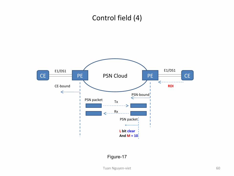
Control field (4)
60
Figure-17
PSN CloudPE PECE CE
PSN packet
CE-bound
E1/DS1 E1/DS1
PSN-bound
L bit clearAnd M = 10
PSN packet
Tx
Rx
RDI
Tuan Nguyen-viet
Fragmentation field
• This field is used for fragmenting multiframe structures into multiple packets as described in 9.2.1. of the ITU-T Y.1413.
• The field is used as follows: – FRG =
• 0 0 Indicates that the entire (unfragmented) multi-frame structure is carried in a single packet.
• 0 1 Indicates the packet carrying the first fragment. • 1 0 Indicates the packet carrying the last fragment. • 1 1 Indicates a packet carrying an intermediate fragment.
Slide 61Tuan Nguyen-viet
Length field
• When the LSP path includes an Ethernet link, a minimum packet size of 64 octets is required.– This may require padding to be applied to the interworking packet payload in order to
reach this minimum packet size.– The padding size can be determined from the length field so that the padding can be
extracted at the egress. • The Length field provides, in octets, the size of the MPLS packet payload, and its value is the
sum of: – a) size of the Common interworking indicators; – b) size of the optional timing information; and – c) size of the payload,
• unless this sum equals or exceeds (≥) 64 octets,– in which case the Length field shall be set to zero.
Slide 62Tuan Nguyen-viet
Sequence number (SN) field
• The Sequence number (SN) field is a two-octet field that is used to detect lost packets and packet mis-ordering.
• The sequence number (SN) space is a– 16-bit,– unsigned circular space,
=> set and processed as defined as in the next slides.
Slide 63Tuan Nguyen-viet
SN : Setting the sequence numbers (SN)
• The following procedures apply at the ingress IWF (TDM-to-MPLS direction): – The sequence number (SN) should be set to a random value for the first MPLS packet
transmitted on the interworking LSP. – For each subsequent MPLS packet, the sequence number (SN) shall be incremented by 1,
modulo 216.
Slide 64Tuan Nguyen-viet
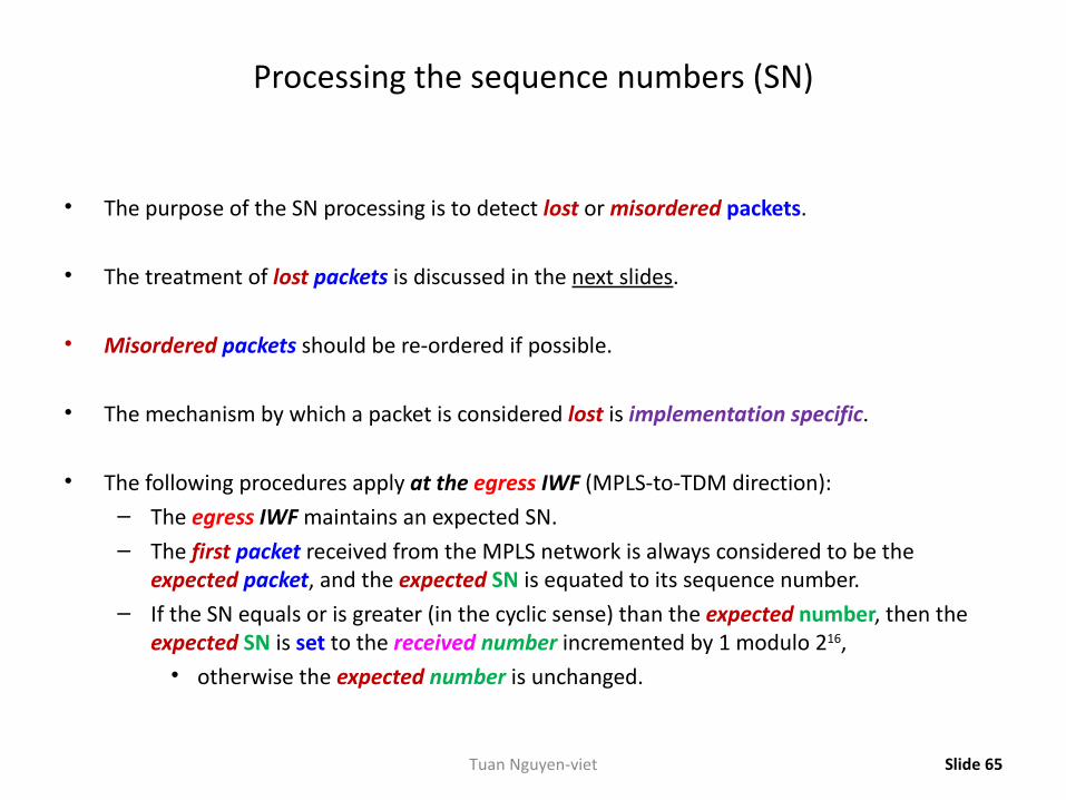
Processing the sequence numbers (SN)
• The purpose of the SN processing is to detect lost or misordered packets.
• The treatment of lost packets is discussed in the next slides.
• Misordered packets should be re-ordered if possible.
• The mechanism by which a packet is considered lost is implementation specific.
• The following procedures apply at the egress IWF (MPLS-to-TDM direction): – The egress IWF maintains an expected SN. – The first packet received from the MPLS network is always considered to be the
expected packet, and the expected SN is equated to its sequence number. – If the SN equals or is greater (in the cyclic sense) than the expected number, then the
expected SN is set to the received number incremented by 1 modulo 216,• otherwise the expected number is unchanged.
Slide 65Tuan Nguyen-viet
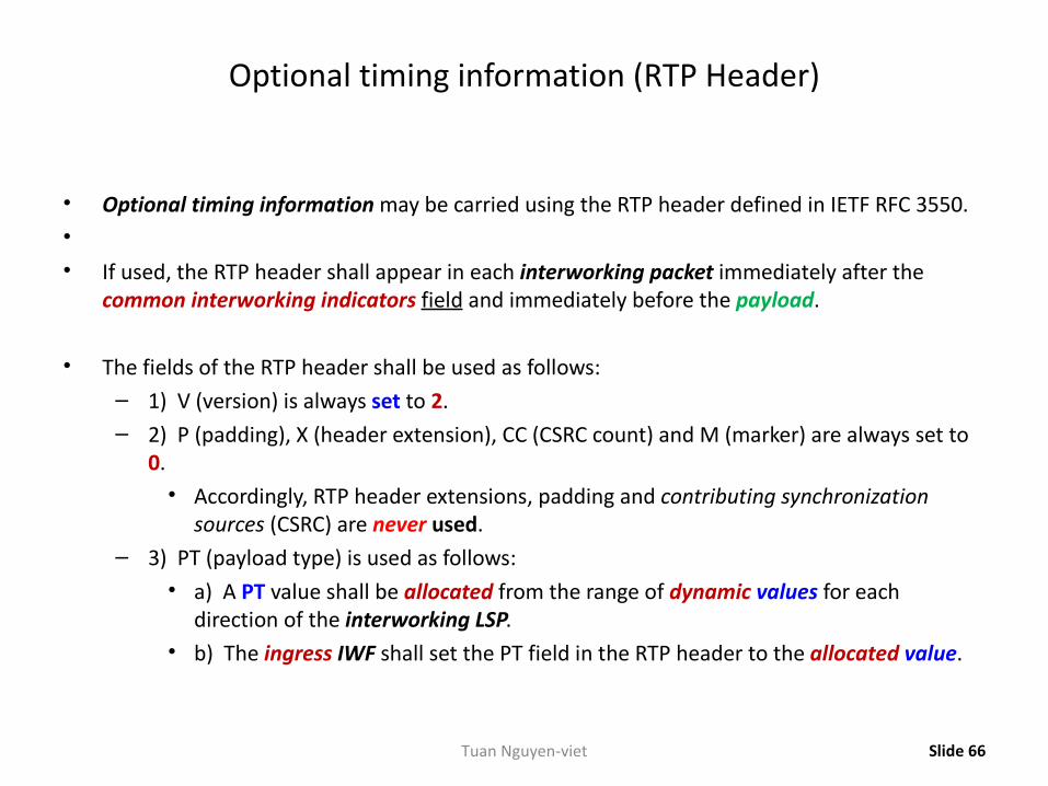
Optional timing information (RTP Header)
• Optional timing information may be carried using the RTP header defined in IETF RFC 3550.• • If used, the RTP header shall appear in each interworking packet immediately after the
common interworking indicators field and immediately before the payload.
• The fields of the RTP header shall be used as follows: – 1) V (version) is always set to 2. – 2) P (padding), X (header extension), CC (CSRC count) and M (marker) are always set to
0. • Accordingly, RTP header extensions, padding and contributing synchronization
sources (CSRC) are never used. – 3) PT (payload type) is used as follows:
• a) A PT value shall be allocated from the range of dynamic values for each direction of the interworking LSP.
• b) The ingress IWF shall set the PT field in the RTP header to the allocated value.
Slide 66Tuan Nguyen-viet
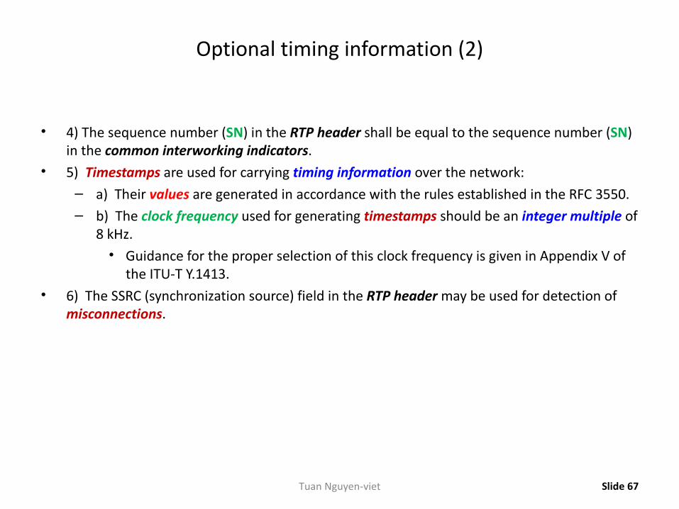
Optional timing information (2)
• 4) The sequence number (SN) in the RTP header shall be equal to the sequence number (SN) in the common interworking indicators.
• 5) Timestamps are used for carrying timing information over the network: – a) Their values are generated in accordance with the rules established in the RFC 3550. – b) The clock frequency used for generating timestamps should be an integer multiple of
8 kHz.• Guidance for the proper selection of this clock frequency is given in Appendix V of
the ITU-T Y.1413. • 6) The SSRC (synchronization source) field in the RTP header may be used for detection of
misconnections.
Slide 67Tuan Nguyen-viet
Payload formats for Structure-aware transport
• Structure-aware transport maintains correct operation of the remote TDM interface by removing structure overhead at ingress and regenerating it at egress, and preserves integrity of the TDM structure by
– structure-locking or– structure indication.
Slide 68Tuan Nguyen-viet
Structure-locked encapsulation
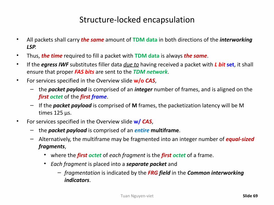
• All packets shall carry the same amount of TDM data in both directions of the interworking LSP.
• Thus, the time required to fill a packet with TDM data is always the same. • If the egress IWF substitutes filler data due to having received a packet with L bit set, it shall
ensure that proper FAS bits are sent to the TDM network.• For services specified in the Overview slide w/o CAS,
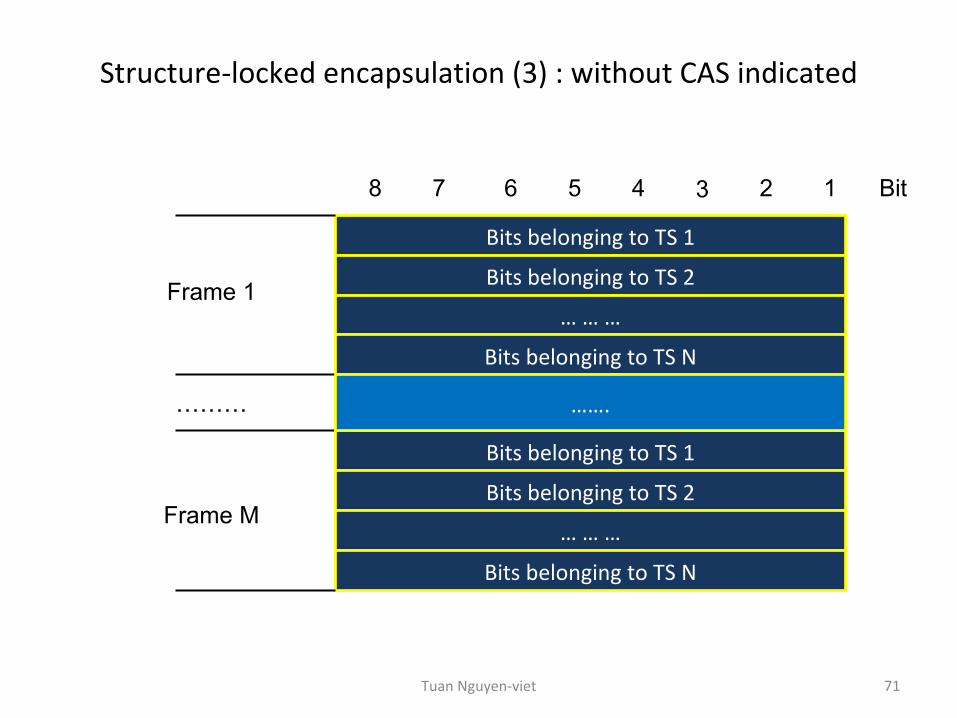
– the packet payload is comprised of an integer number of frames, and is aligned on the first octet of the first frame.
– If the packet payload is comprised of M frames, the packetization latency will be M times 125 µs.
• For services specified in the Overview slide w/ CAS,– the packet payload is comprised of an entire multiframe. – Alternatively, the multiframe may be fragmented into an integer number of equal-sized
fragments,• where the first octet of each fragment is the first octet of a frame.• Each fragment is placed into a separate packet and
– fragmentation is indicated by the FRG field in the Common interworking indicators.
Slide 69Tuan Nguyen-viet
Structure-locked encapsulation (2)
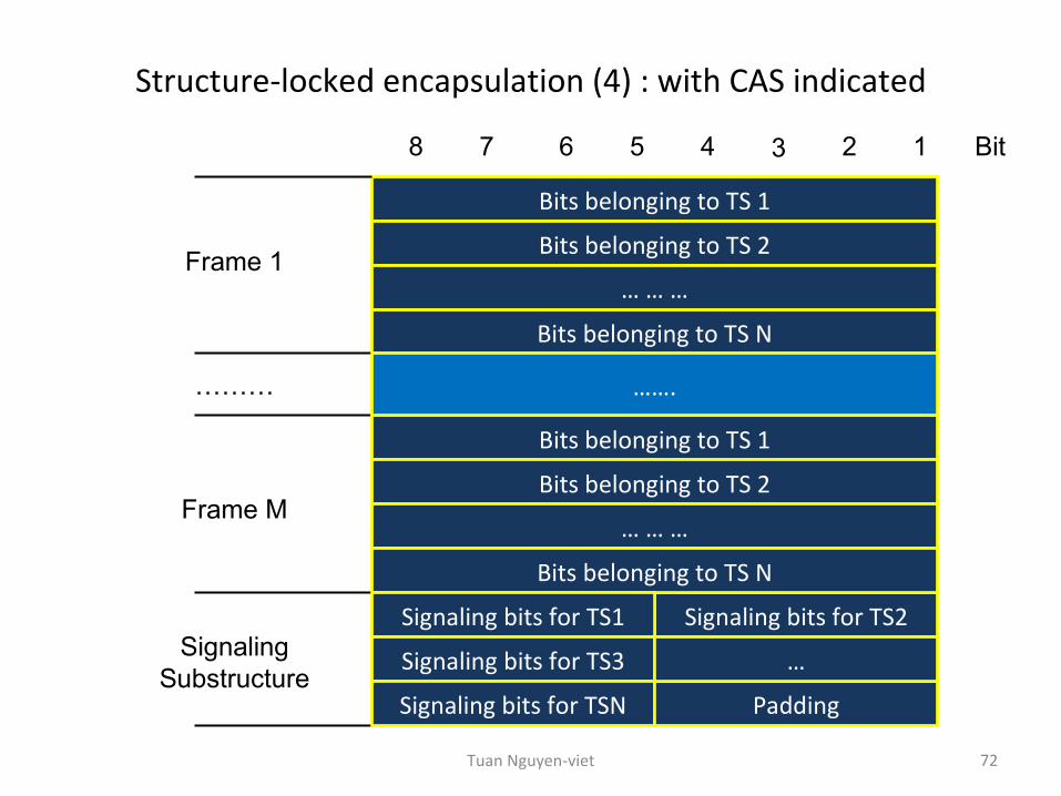
• The CAS signalling information shall be appended as a dedicated signalling substructure, as follows:
– The four CAS bits belonging to each consecutive timeslot are placed in the signalling substructure;
– The CAS bits A, B, C, and D are positioned from most significant to least significant bit of the nibble;
– If the number of timeslots is odd,• a padding nibble shall be appended in order to maintain octet alignment;
– If the multiframe structure is fragmented among several packets,• the signalling substructure is always appended to the last fragment of the
structure.
Slide 70Tuan Nguyen-viet
Structure-locked encapsulation (3) : without CAS indicated
71
Bits belonging to TS 1
12345678 Bit
Bits belonging to TS 2
… … …
Bits belonging to TS N
Frame 1
Bits belonging to TS 1
Bits belonging to TS 2
… … …
Bits belonging to TS N
Frame M
…….………
Tuan Nguyen-viet
Structure-locked encapsulation (4) : with CAS indicated
72
Bits belonging to TS 1
Signaling bits for TS2
12345678 Bit
Bits belonging to TS 2
… … …
Bits belonging to TS N
Frame 1
Bits belonging to TS 1
Bits belonging to TS 2
… … …
Bits belonging to TS N
Frame M
Signaling Substructure
Signaling bits for TS1
Signaling bits for TS3
Signaling bits for TSN Padding
…
…….………
Tuan Nguyen-viet
Structure-indicated encapsulation
• For this encapsulation the TDM bit stream is adapted using AAL Type 1, as described in ATM af-vtoa-0078.000 and ITU-T I.363.1, to form 48-octet AAL Type 1 SAR PDUs.
• The packet payload consists of one or more PDUs, as depicted in Figures on the next slide.– The number of PDUs per packet:
• shall be defined upon initialization;• may be exchanged using a signaling protocol;• shall be the same for both directions; and• shall remain unchanged for the lifespan of the connection.
Slide 73Tuan Nguyen-viet
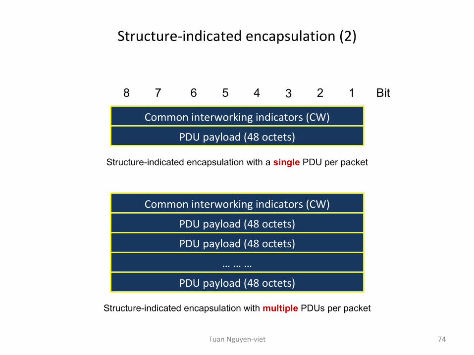
Structure-indicated encapsulation (2)
74
Common interworking indicators (CW)
12345678 Bit
PDU payload (48 octets)
Structure-indicated encapsulation with a single PDU per packet
Common interworking indicators (CW)
PDU payload (48 octets)
… … …
PDU payload (48 octets)
PDU payload (48 octets)
Structure-indicated encapsulation with multiple PDUs per packet
Tuan Nguyen-viet
Structure-indicated encapsulation (3)
• For structure-aware transport (CESoPSN), ATM af-vtoa-0078.000 defines two modes,– Structured and– Structured with CAS.
• Structured AAL type 1– carries byte-aligned TDM and– maintains TDM frame synchronization
• by embedding a pointer to the beginning of the next frame in the SAR-PDU header.• Structured AAL type 1 with CAS
– carries byte-aligned TDM and– maintains TDM frame and multi-frame synchronization
• by embedding a pointer to the beginning of the next multi-frame;• it furthermore contains a substructure including the CAS signaling bits.
Slide 75Tuan Nguyen-viet

Part 6: MFA-8
76Tuan Nguyen-viet
Introduction
• A method for encapsulating TDM signals belonging to the PDH hierarchy (DS1, E1, DS3, E3, Nx64 kbit/s) as pseudo-wires over a MPLS network (MPLS-based PSN).
• Fully aligned with the architecture of pseudo-wire emulation edge-to-edge (PWE3) described in draft-ietf-pwe3-arch-07.txt that has now been the RFC3985, March 2005.
• Structure-aware emulation:– assumes that the TDM framing and control information are
• detected and• possibly stripped from the TDM bit-stream at ingress, and are• regenerated at egress by the appropriate Native Service Processing (NSP) blocks.
– The encapsulation• treats the results of this processing as structured bit-streams in RFC3985, and• preserves the structures across the PSN.
Slide 77Tuan Nguyen-viet
Introduction (2)
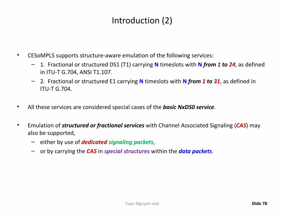
• CESoMPLS supports structure-aware emulation of the following services: – 1. Fractional or structured DS1 (T1) carrying N timeslots with N from 1 to 24, as defined
in ITU-T G.704, ANSI T1.107.– 2. Fractional or structured E1 carrying N timeslots with N from 1 to 31, as defined in
ITU-T G.704.
• All these services are considered special cases of the basic NxDS0 service.
• Emulation of structured or fractional services with Channel Associated Signaling (CAS) may also be supported,
– either by use of dedicated signaling packets,– or by carrying the CAS in special structures within the data packets.
Slide 78Tuan Nguyen-viet
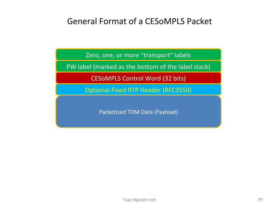
General Format of a CESoMPLS Packet
79
PW label (marked as the bottom of the label stack)
CESoMPLS Control Word (32 bits)
Optional Fixed RTP Header (RFC3550)
Packetized TDM Data (Payload)
Zero, one, or more "transport" labels
Tuan Nguyen-viet
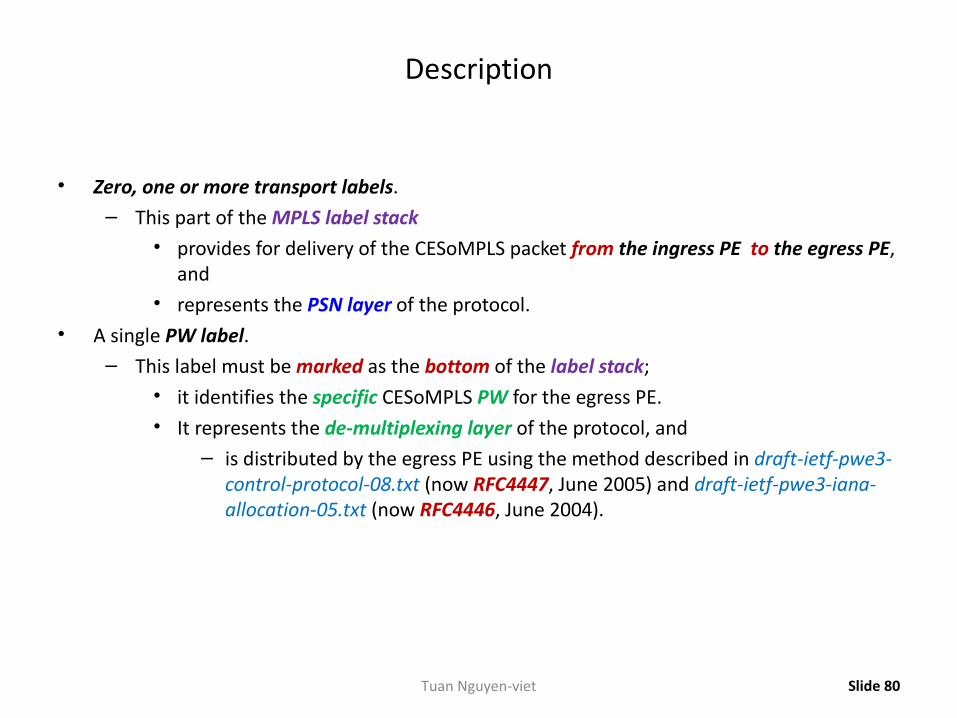
Description
• Zero, one or more transport labels.– This part of the MPLS label stack
• provides for delivery of the CESoMPLS packet from the ingress PE to the egress PE, and
• represents the PSN layer of the protocol.• A single PW label.
– This label must be marked as the bottom of the label stack;• it identifies the specific CESoMPLS PW for the egress PE.• It represents the de-multiplexing layer of the protocol, and
– is distributed by the egress PE using the method described in draft-ietf-pwe3-control-protocol-08.txt (now RFC4447, June 2005) and draft-ietf-pwe3-iana-allocation-05.txt (now RFC4446, June 2004).
Slide 80Tuan Nguyen-viet
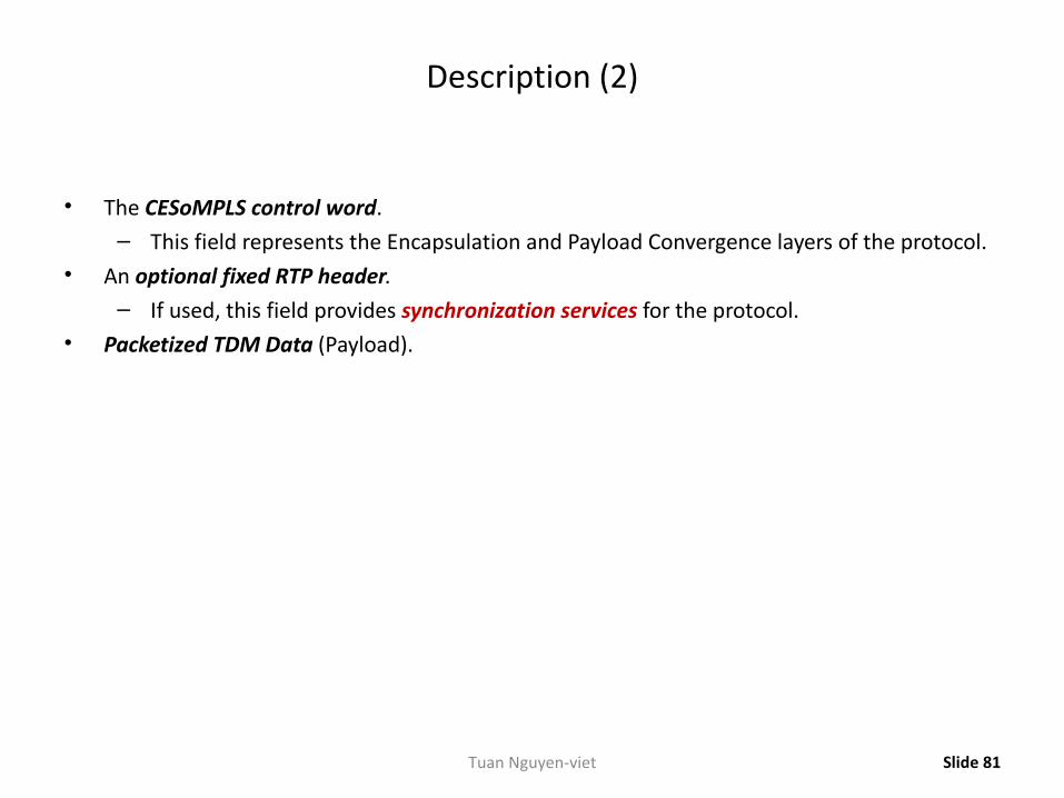
Description (2)
• The CESoMPLS control word.– This field represents the Encapsulation and Payload Convergence layers of the protocol.
• An optional fixed RTP header.– If used, this field provides synchronization services for the protocol.
• Packetized TDM Data (Payload).
Slide 81Tuan Nguyen-viet
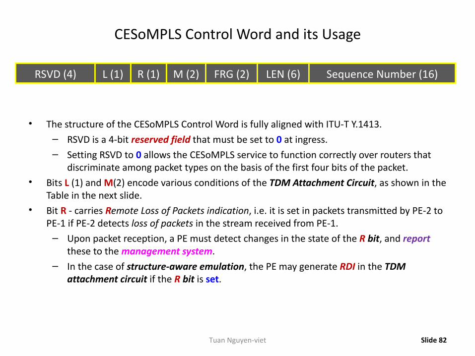
CESoMPLS Control Word and its Usage
• The structure of the CESoMPLS Control Word is fully aligned with ITU-T Y.1413.– RSVD is a 4-bit reserved field that must be set to 0 at ingress.– Setting RSVD to 0 allows the CESoMPLS service to function correctly over routers that
discriminate among packet types on the basis of the first four bits of the packet.• Bits L (1) and M(2) encode various conditions of the TDM Attachment Circuit, as shown in the
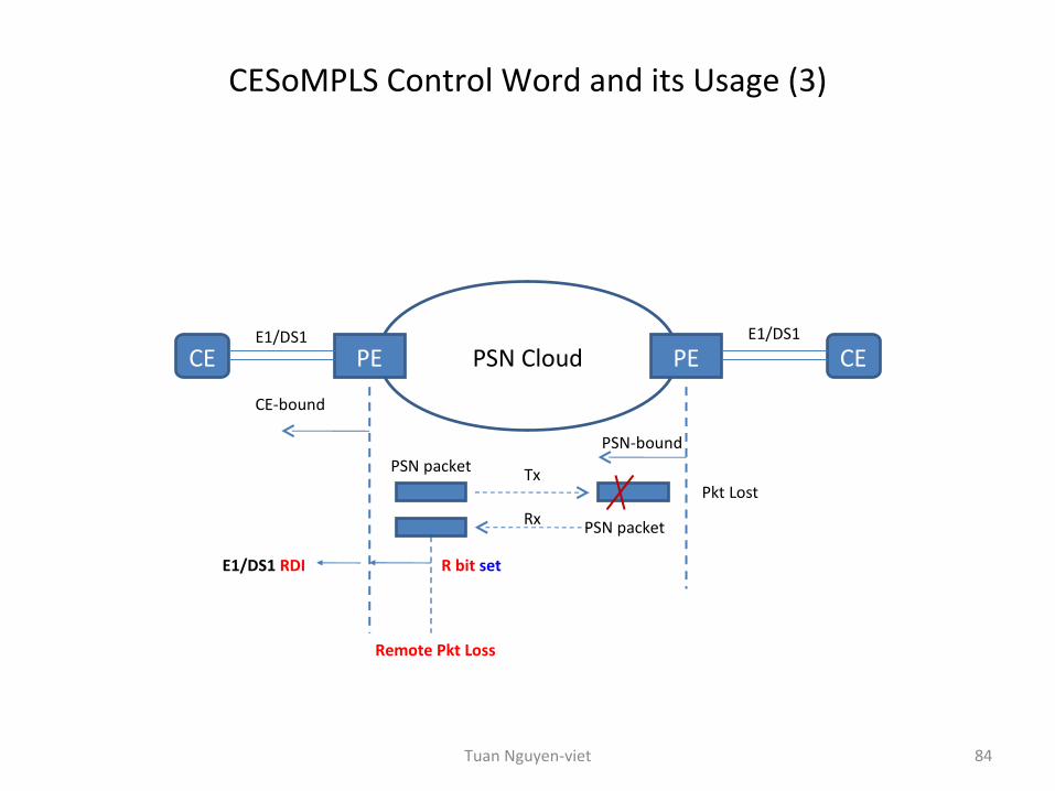
Table in the next slide.• Bit R - carries Remote Loss of Packets indication, i.e. it is set in packets transmitted by PE-2 to
PE-1 if PE-2 detects loss of packets in the stream received from PE-1.– Upon packet reception, a PE must detect changes in the state of the R bit, and report
these to the management system.– In the case of structure-aware emulation, the PE may generate RDI in the TDM
attachment circuit if the R bit is set.
Slide 82
RSVD (4) L (1) R (1) M (2) FRG (2) LEN (6) Sequence Number (16)
Tuan Nguyen-viet
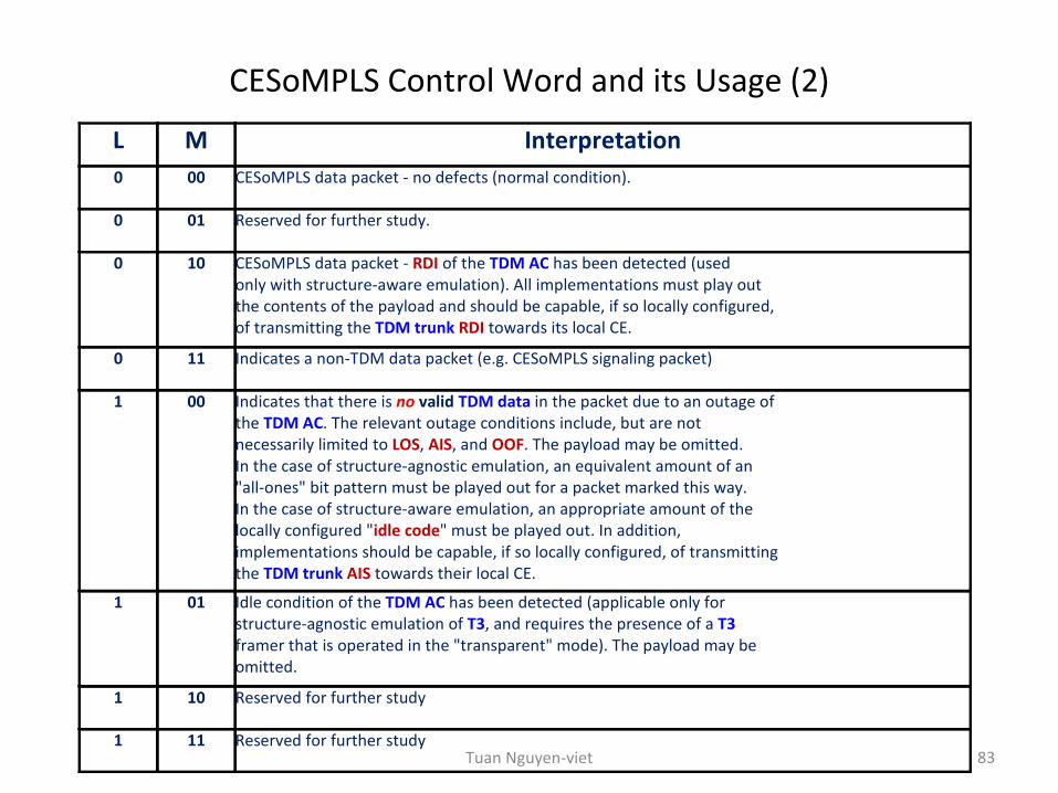
CESoMPLS Control Word and its Usage (2)
83
L M Interpretation0 00 CESoMPLS data packet - no defects (normal condition).
0 01 Reserved for further study.
0 10 CESoMPLS data packet - RDI of the TDM AC has been detected (used only with structure-aware emulation). All implementations must play out the contents of the payload and should be capable, if so locally configured, of transmitting the TDM trunk RDI towards its local CE.
0 11 Indicates a non-TDM data packet (e.g. CESoMPLS signaling packet)
1 00 Indicates that there is no valid TDM data in the packet due to an outage of the TDM AC. The relevant outage conditions include, but are not necessarily limited to LOS, AIS, and OOF. The payload may be omitted. In the case of structure-agnostic emulation, an equivalent amount of an "all-ones" bit pattern must be played out for a packet marked this way. In the case of structure-aware emulation, an appropriate amount of the locally configured "idle code" must be played out. In addition, implementations should be capable, if so locally configured, of transmitting the TDM trunk AIS towards their local CE.
1 01 Idle condition of the TDM AC has been detected (applicable only for structure-agnostic emulation of T3, and requires the presence of a T3 framer that is operated in the "transparent" mode). The payload may be omitted.
1 10 Reserved for further study
1 11 Reserved for further studyTuan Nguyen-viet
CESoMPLS Control Word and its Usage (3)
84
PSN CloudPE PECE CE
PSN packet
CE-bound
E1/DS1 E1/DS1
PSN-bound
R bit set
Remote Pkt Loss
PSN packet
Tx
Rx
Pkt Lost
E1/DS1 RDI
Tuan Nguyen-viet
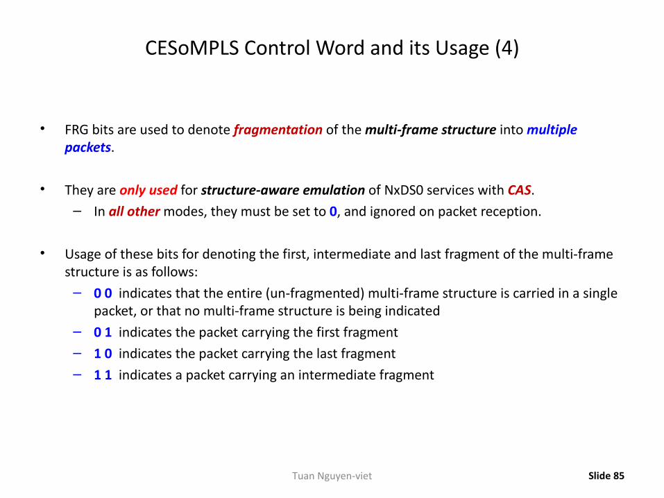
CESoMPLS Control Word and its Usage (4)
• FRG bits are used to denote fragmentation of the multi-frame structure into multiple packets.
• They are only used for structure-aware emulation of NxDS0 services with CAS.– In all other modes, they must be set to 0, and ignored on packet reception.
• Usage of these bits for denoting the first, intermediate and last fragment of the multi-frame structure is as follows:
– 0 0 indicates that the entire (un-fragmented) multi-frame structure is carried in a single packet, or that no multi-frame structure is being indicated
– 0 1 indicates the packet carrying the first fragment – 1 0 indicates the packet carrying the last fragment – 1 1 indicates a packet carrying an intermediate fragment
Slide 85Tuan Nguyen-viet
CESoMPLS Control Word and its Usage (5)
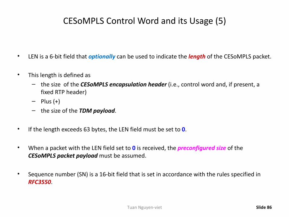
• LEN is a 6-bit field that optionally can be used to indicate the length of the CESoMPLS packet.
• This length is defined as– the size of the CESoMPLS encapsulation header (i.e., control word and, if present, a
fixed RTP header)– Plus (+)– the size of the TDM payload.
• If the length exceeds 63 bytes, the LEN field must be set to 0.
• When a packet with the LEN field set to 0 is received, the preconfigured size of the CESoMPLS packet payload must be assumed.
• Sequence number (SN) is a 16-bit field that is set in accordance with the rules specified in RFC3550.
Slide 86Tuan Nguyen-viet
Usage of the Fixed RTP Header Fields
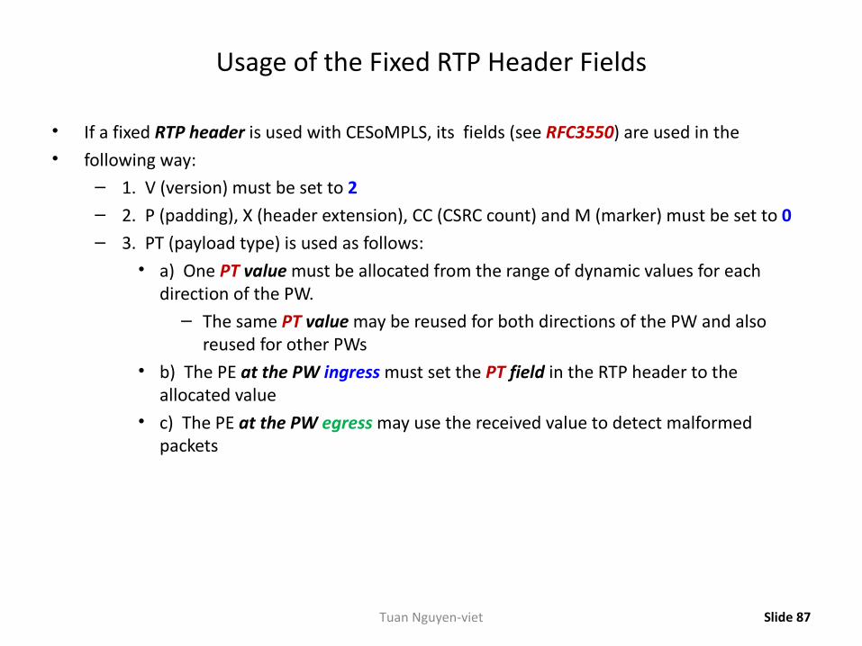
• If a fixed RTP header is used with CESoMPLS, its fields (see RFC3550) are used in the • following way:
– 1. V (version) must be set to 2 – 2. P (padding), X (header extension), CC (CSRC count) and M (marker) must be set to 0 – 3. PT (payload type) is used as follows:
• a) One PT value must be allocated from the range of dynamic values for each direction of the PW.
– The same PT value may be reused for both directions of the PW and also reused for other PWs
• b) The PE at the PW ingress must set the PT field in the RTP header to the allocated value
• c) The PE at the PW egress may use the received value to detect malformed packets
Slide 87Tuan Nguyen-viet
Usage of the Fixed RTP Header Fields (2): Payload Types
Slide 88
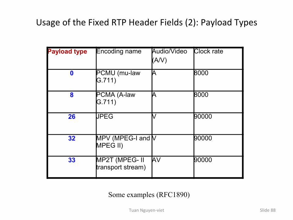
Payload type Encoding name Audio/Video (A/V)
Clock rate
0 PCMU (mu-law G.711)
A 8000
8 PCMA (A-law G.711)
A 8000
26 JPEG V 90000
32 MPV (MPEG-I and MPEG II)
V 90000
33 MP2T (MPEG- II transport stream)
AV 90000
Some examples (RFC1890)
Tuan Nguyen-viet
Usage of the Fixed RTP Header Fields (3)
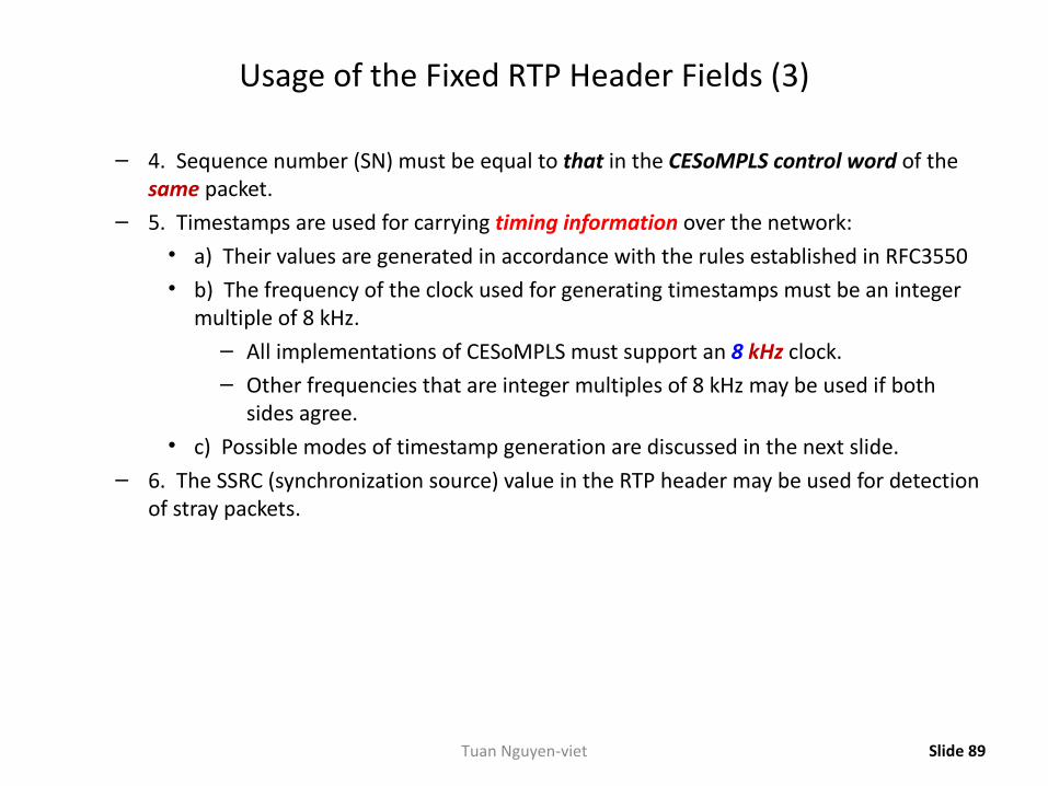
– 4. Sequence number (SN) must be equal to that in the CESoMPLS control word of the same packet.
– 5. Timestamps are used for carrying timing information over the network: • a) Their values are generated in accordance with the rules established in RFC3550 • b) The frequency of the clock used for generating timestamps must be an integer
multiple of 8 kHz.– All implementations of CESoMPLS must support an 8 kHz clock.– Other frequencies that are integer multiples of 8 kHz may be used if both
sides agree. • c) Possible modes of timestamp generation are discussed in the next slide.
– 6. The SSRC (synchronization source) value in the RTP header may be used for detection of stray packets.
Slide 89Tuan Nguyen-viet
Usage of the Fixed RTP Header Fields (4)
• The RTP header in CESoMPLS can be used in conjunction with at least the following modes of timestamp generation:
– 1. Absolute mode:• The ingress PE sets timestamps using the clock recovered from the incoming TDM
circuit.• As a consequence, the timestamps are closely correlated with the sequence
numbers.• All CESoMPLS implementations must support this mode
– 2. Differential mode:• The two PE devices connected by the PW must have access to the same high-
quality synchronization source, and this synchronization source must be used for timestamp generation.
• Support of this mode is optional.
Slide 90Tuan Nguyen-viet
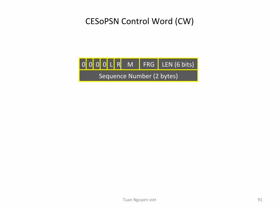
CESoPSN Control Word (CW)
91
0 0 0 0 L R M FRG LEN (6 bits)
Sequence Number (2 bytes)
Tuan Nguyen-viet