Embed Size (px)
Citation preview
CERN VIBRATION SENSOR PROPOSAL
The research leading to these results has received funding from the European Commission under the FP7 Research Infrastructures project EuCARD
K. Artoos, C. Collette, R. Leuxe, C.Eymin, P. Fernandez, S. Janssens*
2
Outline
Vibration Control with sensor Proposed sensitivity curve Proposed noise curve Environmental conditions Form of tender Some tests made
3
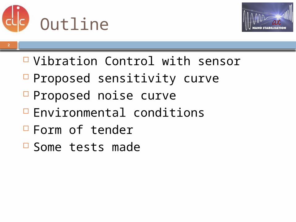
Integrated luminosity simulations
No stabilization 68% luminosity lossSeismometer FB maximum gain
13%
Seismometer FB medium gain 6% (reduced peaks @ 0.1 and 75 Hz)
Seismometer FB maximum gain +FF
7%
Inertial reference mass 11%Inertial reference. mass. + HP filter
3% to 0.7% for higher freq
Courtesy J. Snuverink et al.Commercial Seismometer
Custom Inertial Reference mass
S. Janssens, P. Fernandez, A&T Sector Seminar, Geneva, 24 November 2011
4
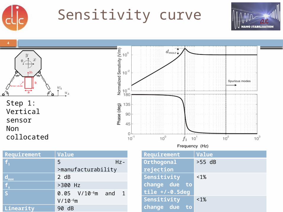
Sensitivity curve
Requirement Valuef1 5 Hz->manufacturability dmax 2 dBfs >300 HzS 0.05 V/10-6m and 1
V/10-6mLinearity 90 dBMax DC offset 0.5 Vm <1.5 kg
Requirement ValueOrthogonal rejection
>55 dB
Sensitivity change due to tile +/-0.5deg
<1%
Sensitivity change due to tile +/-0.5deg
<1%
Step 1:Vertical sensorNon collocated
5
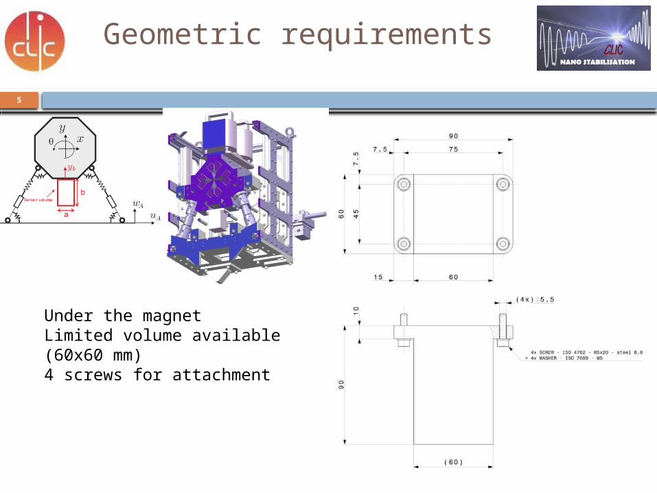
Geometric requirements
Under the magnetLimited volume available (60x60 mm)4 screws for attachment
6
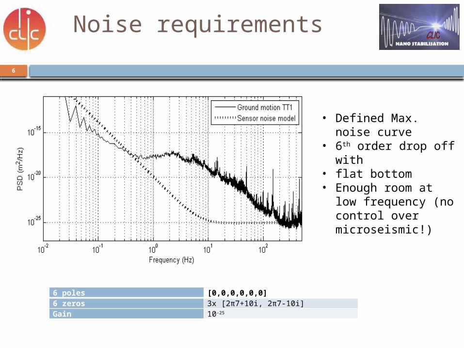
Noise requirements
6 poles [0,0,0,0,0,0]6 zeros 3x [2π7+10i, 2π7-10i]Gain 10-25
• Defined Max. noise curve
• 6th order drop off with
• flat bottom • Enough room at low
frequency (no control over microseismic!)
7
Noise requirements
10-2
10-1
100
101
102
10-1
100
Frequency [Hz]
Tw
x [-]
Twx
no noise
Twx
noise
10-1
100
101
102
10-11
10-10
10-9
10-8
10-7
10-6
[m]
[Hz]
ground (f)
quad+noise
(f)
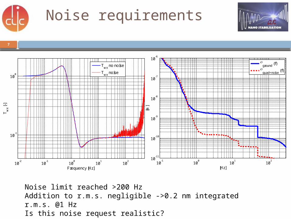
Noise limit reached >200 HzAddition to r.m.s. negligible ->0.2 nm integrated r.m.s. @1 HzIs this noise request realistic?
8
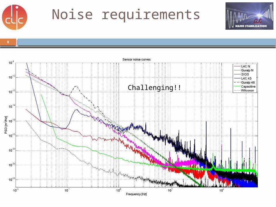
Noise requirements
Challenging!!
S. Janssens, CLIC Workshop, January 2013
9
Inertial reference mass proto (v3): With interferometer/with capacitive gauge
10
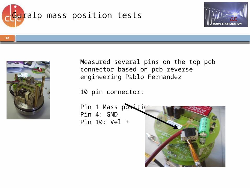
Guralp mass position tests
Measured several pins on the top pcb connector based on pcb reverse engineering Pablo Fernandez
10 pin connector:
Pin 1 Mass positionPin 4: GNDPin 10: Vel +
11
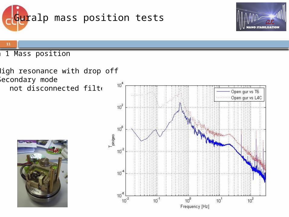
Guralp mass position tests
Pin 1 Mass position
• High resonance with drop off• Secondary mode not disconnected filter?
12
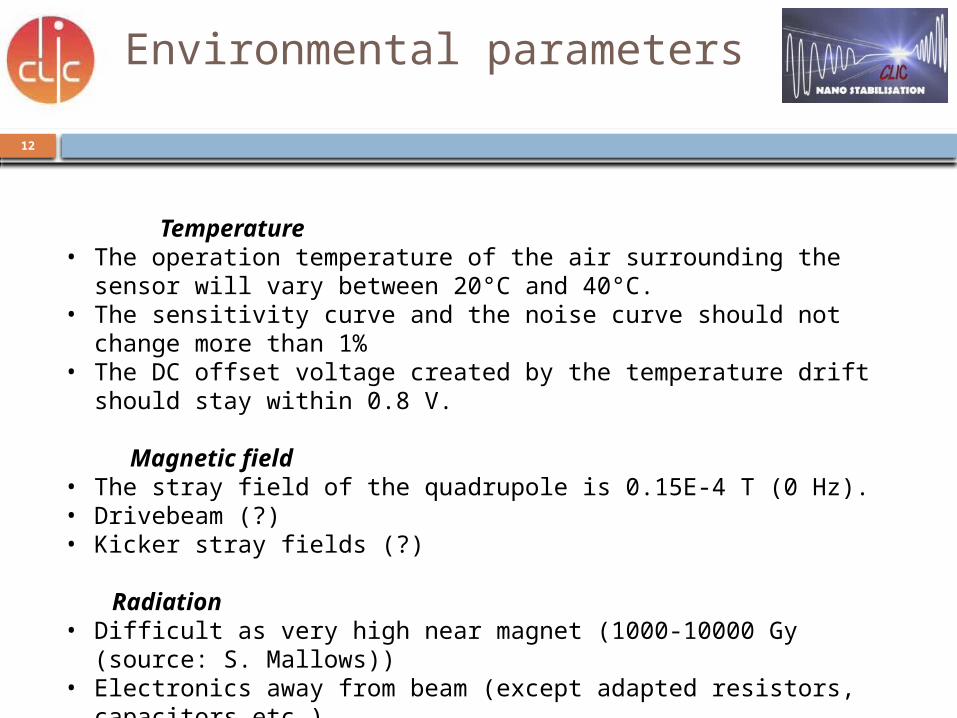
Environmental parameters
Temperature• The operation temperature of the air surrounding the sensor will
vary between 20°C and 40°C. • The sensitivity curve and the noise curve should not change more
than 1%• The DC offset voltage created by the temperature drift should stay
within 0.8 V.
Magnetic field• The stray field of the quadrupole is 0.15E-4 T (0 Hz). • Drivebeam (?)• Kicker stray fields (?)
Radiation• Difficult as very high near magnet (1000-10000 Gy (source: S.
Mallows))• Electronics away from beam (except adapted resistors, capacitors
etc.)
13
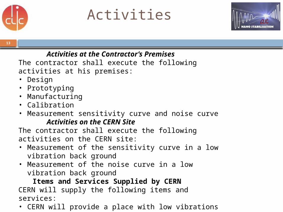
Activities
Activities at the Contractor’s PremisesThe contractor shall execute the following activities at his premises:• Design• Prototyping• Manufacturing• Calibration• Measurement sensitivity curve and noise curve
Activities on the CERN SiteThe contractor shall execute the following activities on the CERN site:• Measurement of the sensitivity curve in a low vibration
back ground• Measurement of the noise curve in a low vibration back
groundItems and Services Supplied by CERN
CERN will supply the following items and services:• CERN will provide a place with low vibrations• CERN will provide during the measurement of the
sensitivity curve, a Guralp 6T seismometer with calibration certificate.
• CERN will provide the shielding around the power supply, the conditioners and electronics.
14
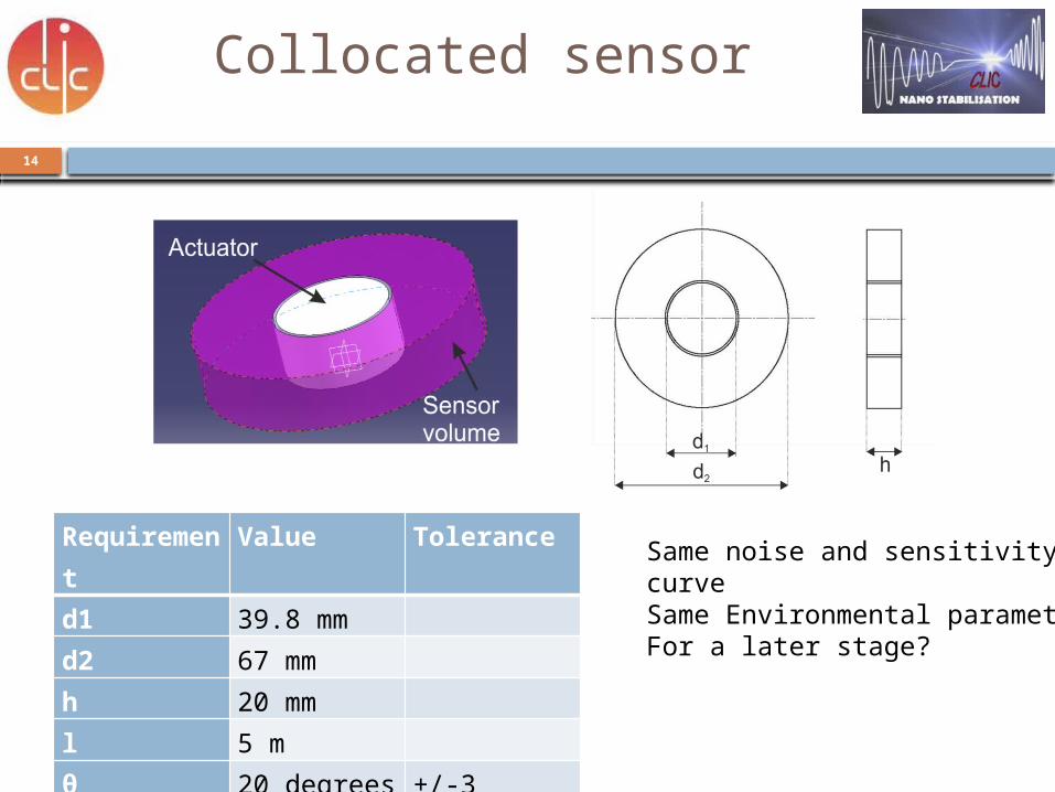
Collocated sensor
Requirement
Value Tolerance
d1 39.8 mm d2 67 mm h 20 mm l 5 m θ 20 degrees +/-3m 0.6 kg
Same noise and sensitivity curveSame Environmental parametersFor a later stage?
15
Conclusion
• From beam simulations a preferred sensor sensitivity is determined
• The volume to fit in the type 1 and type 4 full stabilization is limited to 60x60x60 mm
• The chosen maximum noise curve is challenging but possible
• The environmental parameters are standard except for the radiation => electronics outside of highly radiated area
Note: 20th of March we will have visitors from the Fraunhofer institute to test their accelerometer