Embed Size (px)
Citation preview
CERAMICS FOR SMALL RADIAL INFLOW POWER GENERATORS
Arthur G. Metcalfe and James C. Napier
Solar Turbines International, an Operating Group of International Harvester 2200 Pacific Highway San Diego, CA 92138
INTRODUCTION
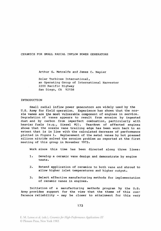
Small radial inflow power generators are widely used by the U.S. Army for field operation. Experience has shown that the nozzle vanes are the most vulnerable component of engines in service. Degradation of vanes appears to result from erosion by ingested dust and by carbon from imperfect combustion, particularly with heavier fuels (e.g., Diesel #2). Teardown of affected engines shows that the nozzle vane trailing edge has been worn back to an extent that is in line with the calculated decrease of performance plotted in Figure 1. Replacement of the metal vanes by hot pressed silicon nitride solved the erosion problem as reported at the first meeting of this group in November 1973.
Work since this time has been directed along three lines:
1. Develop a ceramic vane design and demonstrate by engine tests.
2. Extend application of ceramics to both vane and shroud to allow higher inlet temperatures and higher output.
3. Select effective manufacturing methods for implementation of ceramic vanes in engines.
Initiation of a Army provides support ference reliability -
manufacturing methods program by the U.S. for the view that the theme of this con
may be closer to attainment for this very
173
E. M. Lenoe et al. (eds.), Ceramics for High-Performance Applications III© Plenum Press, New York 1983
174 A. G. METCALFE AND J. C. NAPIER
1oor------------:~~~::::::==~------------------------,_----~200 '/. POWER
80 150
u 60 u.
Vl oe ::;; ..,
::> ~ 0 '/.SFC 100 ~ c.. ....
40
50 20
°0~-------------71~0------------~2~0~------------~30~-------------l400
EROSION/VANE LENGTH '/.
Figure 1. Relative Performance Loss With Nozzle Vane Erosion in a Small Radial Gas Turbine
special application than for other engines. The reasons for this include the favorable statistics derived from the small component size, the low structural stresses in the ceramic component, the use of the relaxing joint concept and other special conditions. These will be reviewed in the body of this paper.
THE MERADCOM 10 kW AUXILIARY POWER UNIT
I-c.. 0 "-u u. Vl
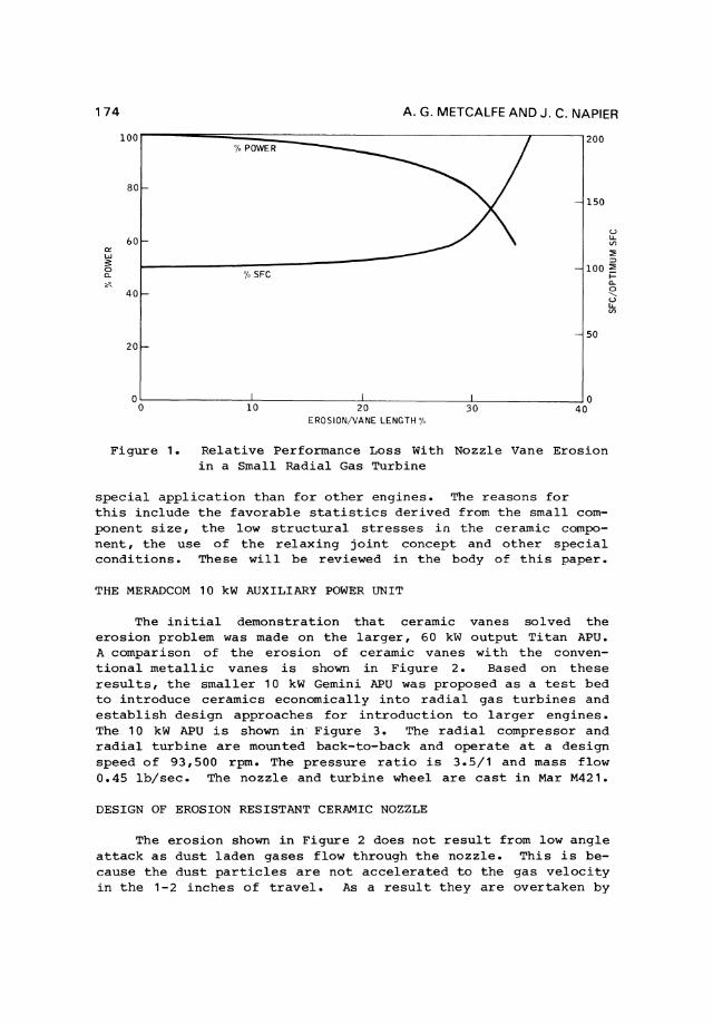
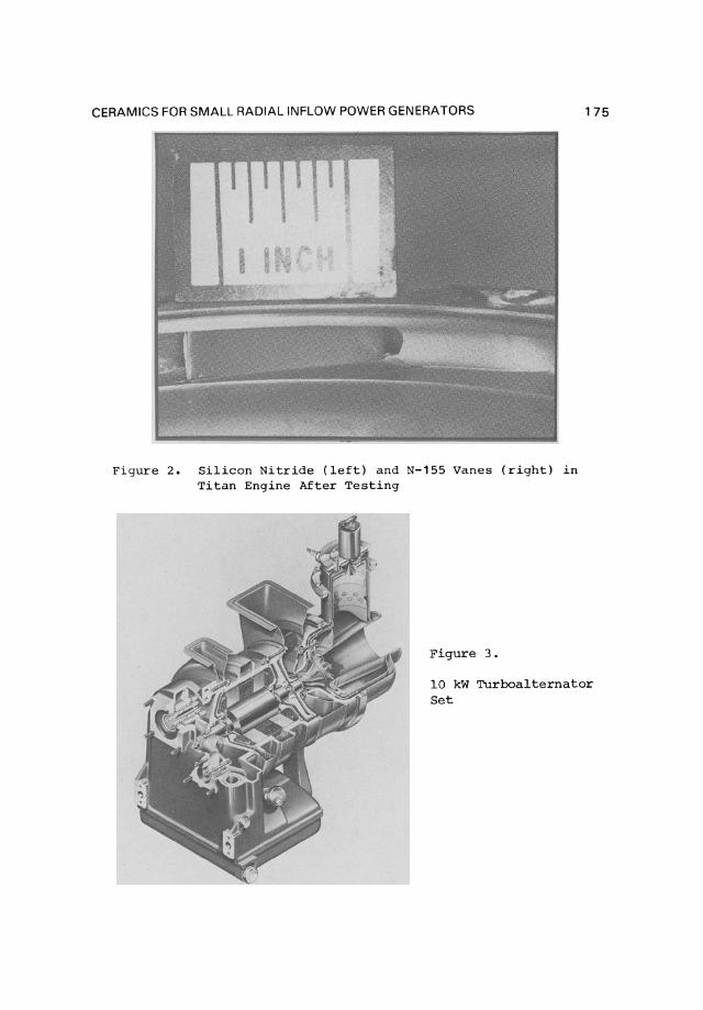
The initial demonstration that ceramic vanes solved the erosion problem was made on the larger, 60 kW output Titan APU. A comparison of the erosion of ceramic vanes with the conventional metallic vanes is shown in Figure 2. Based on these results, the smaller 10 kW Gemini APU was proposed as a test bed to introduce ceramics economically into radial gas turbines and establish design approaches for introduction to larger eng in es. The 10 kW APU is shown in" Figure 3. The radial compressor and radial turbine are mounted back-to-back and operate at a design speed of 93,500 rpm. The pressure ratio is 3.5/1 and mass flow 0.45 lb/sec. The nozzle and turbine wheel are cast in Mar M421.
DESIGN OF EROSION RESISTANT CERAMIC NOZZLE
The erosion shown in Figure 2 does not result from low angle attack as dust laden gases flow through the nozzle. This is because the dust particles are not accelerated to the gas velocity in the 1-2 inches of travel. As a result they are overtaken by
CERAMICS FOR SMALL RADIAL INFLOW POWER GENERATORS
Figure 2. Silicon Nitride (left) and N-155 Vanes (right) in Titan Engine After Testing
Figure 3 .
175
10 kW Turboalternator Set
176 A. G. METCALFE AND J. C. NAPIER
the turbine wheel and batted forward to hit the vanes at a high angle. The relative velocities at the turbine wheel impact are low and little erosion occurs; but they are extremely high at vane impact and cause severe erosion. It was concluded that high velocity, high angle impacts should be used to evaluate candidate nozzle vane materials.
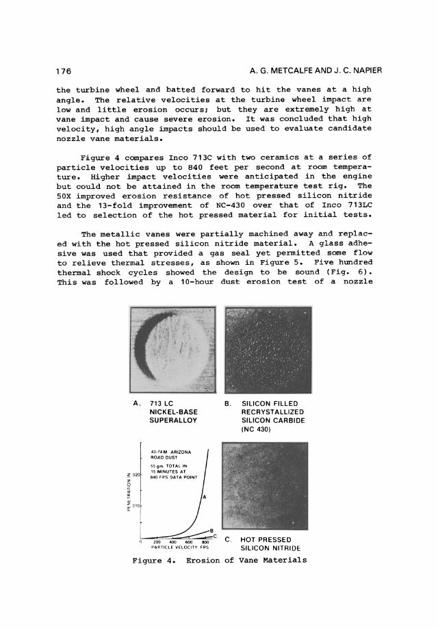
Figure 4 compares Inco 713C with two ceramics at aseries of particle velocities up to 840 feet per second at room temperature. Higher impact velocities were anticipated in the engine but could not be attained in the room temperature test rig. The SOX improved erosion resistance of hot pressed silicon nitride and the 13-fold improvement of NC-430 over that of Inco 713LC led to selection of the hot pressed material for initial tests.
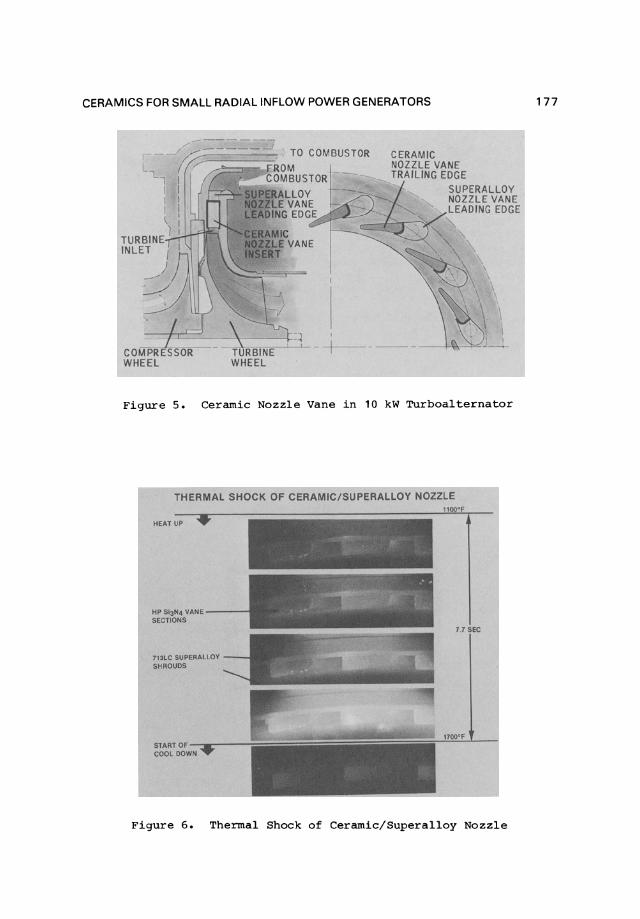
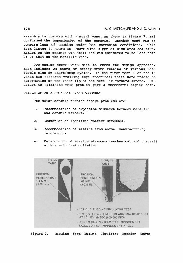
The metallic vanes were partially machined away and replaced with the hot pressed silicon nitride material. A glass adhesive was used that provided a gas seal yet permitted some flow to relieve thermal stresses, as shown in Figure S. Five hundred thermal shock cycles showed the design to be sound (Fig. 6). This was followed by a 10-hour dust erosion test of a nozzle
A. 713 LC B. SILICON FILLED NICKEL-BASE RECRYSTALLIZED SUPERALLOY SILICON CARBIDE
(NC 430)
43-74 M ARIZONA ROAD DUST
55 gm TOTAL IN
020 15 MINUTES AT 840 FPS OATA POINT
010
B C C. 200 HOT PRESSED
PARTIClE VELOCITY FPS SILICON NITRIDE
Figure 4. Erosion of Vane Materials
CERAMICS FOR SMALL RADIAL INFLOW POWER GENERATORS
i..., I ~
TURBINE ) INLET I
1 / _ ....
COMPRESSOR TURBINE WHEEL WHEEL
TO COMBUSTOR CERAMIC NOZZLE VANE TRAILING EDGE
Figure 5. Ceramic Nozzle Vane in 10 kW Turboalternator
THERMAL SHOCK OF CERAMIC/SUPERALLOY NOZZLE
HEATUP •
HP 513014 VANE--SECTIONS
7'3LC SUPERALlOY SHAOUDS
1100"F
~' , ,..
---.' '" " .. ' -.,y- ~,.,
17 SEC
STAATOF-_--..!::::;;;:::::::::::;~~~~~~~~~~ __ J1!!~L__l COOL DOWN
Figure 6. Thermal Shock of Ceramic/Superalloy Nozzle
177
178 A . G. METCALFE AND J. C. NAPIER
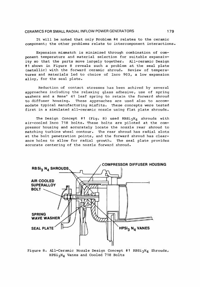
assembly to compare with a metal vane, as shown in Figure 7, and confirmed the superiority of the cerarnic. Another test was to compare loss of section under hot corrosion condi tions. This test lasted 70 hours at 1700 0 F with 3 ppm of simulated sea salto Attack on the cerarnic was small and was estimated to be less than 4% of that on the metallic vane.
Two engine tests were made to check the design approach. Each included 24 hours of steady-state running at various load levels plus 50 start/stop cycles. In the first test 6 of the 15 vanes had suffered trailing edge fracturesl these were traced to deformation of the inner lip of the metallic forward shroud. Redesign to eliminate this problem gave a successful engine test.
DESIGN OF AN ALL-CERAMIC VANE ASSEMBLY
The major cerarnic turbine design problems are:
1. Accornrnodation of expansion mismatch between metallic and cerarnic mernbers.
2. Reduction of localized contact stresses.
3. Accornrnodation of misfits from normal manufacturing tolerances.
4. Maintenance of service stresses (mechanical and thermal) within safe design limits.
EROSION PENETRATION 1.4 MM ( 055 IN.)
EROSION PENETRATION .89 MM (.0035 IN .)
HPSi3N4 VANE
- 10 HOUR TURBINE SIMULATOR TEST
- 1390gm OF 43-74 MICRON ARIZONA ROADDUST AT 251-274 M/SEC,I800-880 FPS)
- 953 CM (3/8 IN ) DIAMETER IMPINGEMENT NOZZLE AT 60' IMPINGEMENT ANGLE
Figure 7. Results from Engine Simulator Erosion Tests
CERAMICS FOR SMALL RADIAL INF-LOW POWER GENERATORS 179
It will be noted that only Problem #4 relates to the ceramic component1 the other problems relate to intercomponent interactions.
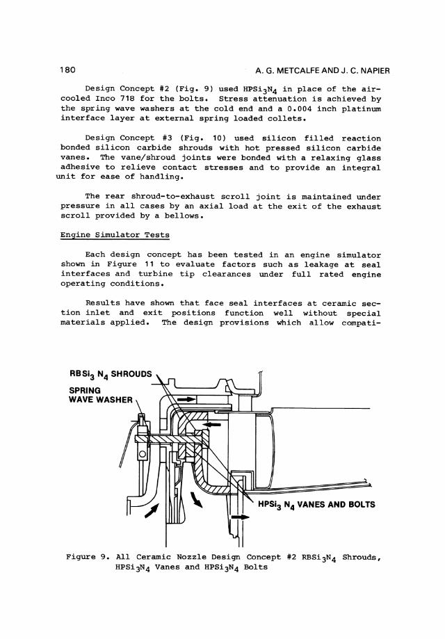
Expansion mismatch is minimized through combination of component temperature and material selection for suitable expansivity so that the parts move largely together. All-ceramic Design #1 shown in Figure 8 reveals such a problem at the seal plate (metallic) wi th the forward ceramic shroud. Review of temperatures and materials led to choice of Inco 903, a low expansion alloy, for the seal plate.
Reduction of contact stresses has been achived by several approaches including the relaxing glass adhesive, use of spring washers and aRene' 41 leaf spring to retain the forward shroud to diffuser housing. These approaches are used also to accommodate typical manufacturing misfits. These concepts were tested first in a simulated all-ceramic nozzle using flat plate shrouds.
The Design Concept #1 (Fig. 8) used RBSi3N4 shrouds with air-cooled Inco 718 bolts. These bolts are piloted at the compressor housing and accurately locate the nozzle re ar shroud to matching turbine wheel contour. The rear shroud has radial slots at the bolt penetration points, and the forward shroud has clearance holes to allow for radial growth. The seal plate provides accurate centering of the nozzle forward shroud.
AIR COOlED SUPERAllOY BOlT
SPRING WAVEWASHER
SEAL PlATE HPSi3 N4 VANES
Figure 8. All-Ceramic Nozzle Design Concept #1 RBSi3N4 Shrouds, HPSi3N4 Vanes and Cooled 718 Bolts
180 A. G. METCALFE AND J. C. NAPIER
Design Concept #2 (Fig. 9) used HPSi3N4 in place of the aircooled Inco 718 for the bolts. Stress attenuation is achieved by the spring wave washers at the cold end and a 0.004 inch platinum interface layer at external spring loaded collets.
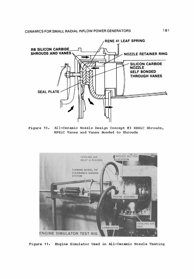
Design Concept #3 (Fig. 10) used silicon filled reaction bonded silicon carbide shrouds with hot pressed silicon carbide vanes. The vane/shroud joints were bonded with a relaxing glass adhesive to relieve contact stresses and to provide an integral
unit for ease of handling.
The rear shroud-to-exhaust scroll joint is maintained under pressure in all cases by an axial load at the exit of the exhaust scroll provided by a bellows.
Engine Simulator Tests
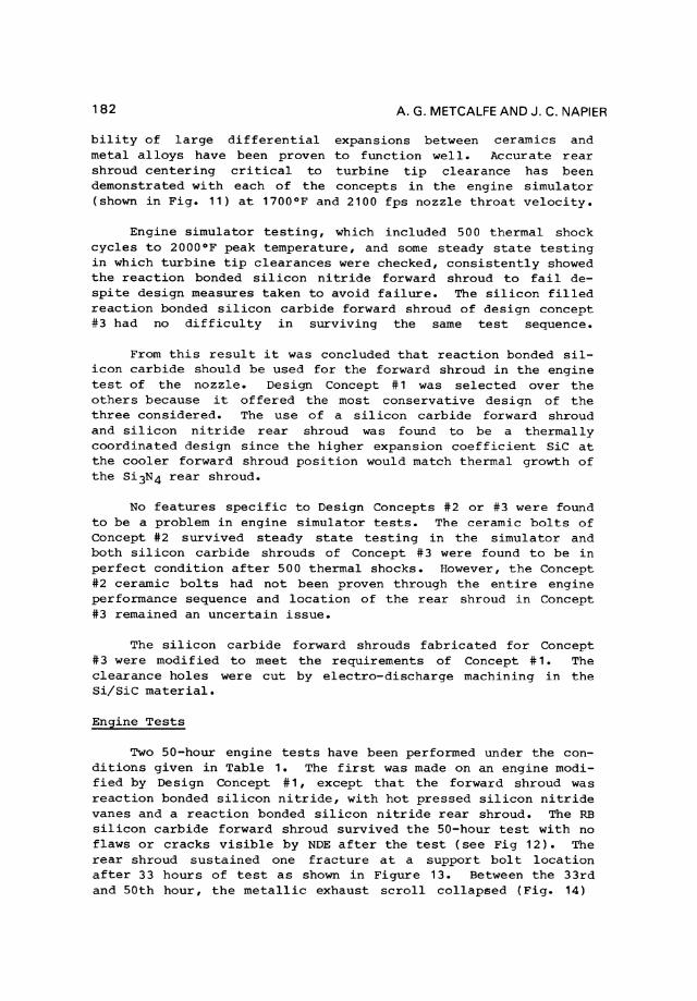
Each design concept has been tested in an engine simulator shown in Figure 11 to evaluate factors such as leakage at seal interfaces and turbine tip clearances under full rated engine operating conditions.
Results have shown that face seal interfaces at ceramic section inlet and exit positions function well without special materials applied. The design provisions which allow compati-
RBSi3 N4 SHROUDS
SPRING WAVE WASHER
HPSi3 N4 VANES AND BOLTS
Figure 9. All Ceramic Nozzle Design Concept #2 RBSi 3N4 Shrouds, HPSi3N4 Vanes and HPSi3N4 Bolts
CERAMICS FOR SMALL RADIAL INFLOW POWER GENERATORS 181
RENE 41 LEAF SPRING
NOZZLE RETAINER RING
SILICON CARBIDE NOZZLE SELF BONDED THROUGH VANES
Figure 10. All-Ceramic Nozzle Design Concept #3 RBSiC Shrouds, HPSiC Vanes and Vanes Bonded to Shrouds
COOLING AIR
TURBINE WHEEL TIP CLEARANCE GAGING SYSTEM
Figure 11. Engine Simulator Used in All-Ceramic Nozzle Testing
182 A. G. METCALFE AND J. C. NAPIER
bility of large differential expansions between ceramics and metal alloys have been proven to function well. Accurate rear shroud centering critical to turbine tip clearance has been demonstrated wi th each of the concepts in the engine simulator (shown in Fig. 11) at 1700°F and 2100 fps nozzle throat velocity.
Engine simulator testing, which included 500 thermal shock cycles to 2000 0 F peak temperature, and some steady state testing in which turbine tip clearances were checked, consistently showed the reaction bonded silicon nitride forward shroud to fail despite design measures taken to avoid failure. The silicon filled reaction bonded silicon carbide forward shroud of design concept #3 had no difficulty in surviving the same test sequence.
From this result it was concluded that reaction bonded silicon carbide should be used for the forward shroud in the engine test of the nozzle. Design Concept #1 was selected over the others because it offered the most conservative design of the three considered. The use of a silicon carbide forward shroud and silicon nitride rear shroud was found to be a thermally coordinated design since the higher expansion coefficient SiC at the cooler forward shroud position would match thermal growth of the Si3N4 re ar shroud.
No features specific to Design Concepts #2 or #3 were found to be a problem in engine simulator tests. The ceramic bolts of Concept #2 survived steady state testing in the simulator and both silicon carbide shrouds of Concept #3 were found to be in perfect condition after 500 thermal shocks. However, the Concept #2 ceramic bolts had not been proven through the entire engine performance sequence and location of the rear shroud in Concept #3 remained an uncertain issue.
The silicon carbide forward shrouds fabricated for Concept #3 were modified to meet the requirements of Concept # 1. The clearance holes were cut by electro-discharge machining in the Si/Sie material.
Engine Tests
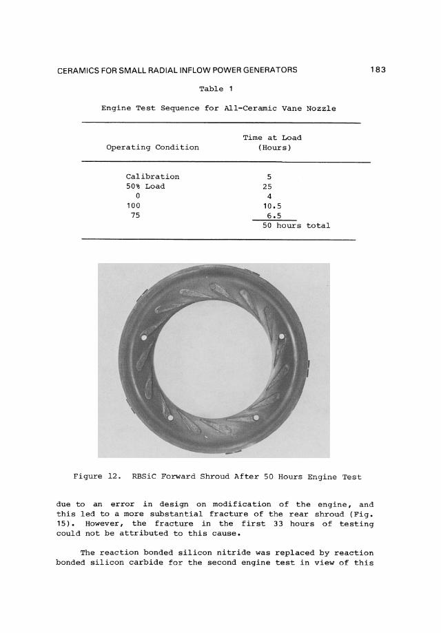
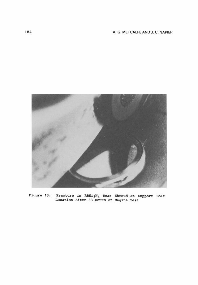
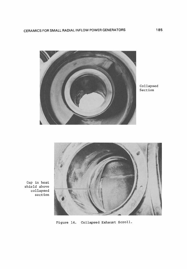
Two 50-hour engine tests have been performed under the conditions given in Table 1. The first was made on an engine modified by Design eoncept #1, except that the forward shroud was reaction bonded silicon nitride, with hot pressed silicon nitride vanes and areaction bonded silicon nitride rear shroud. The RB silicon carbide forward shroud survived the 50-hour test with no flaws or cracks visible by NDE after the test (see Fig 12). The rear shroud sustained one fracture at a support bol t location after 33 hours of test as shown in Figure 13. Between the 33rd and 50th hour, the metallic exhaust scroll collapsed (Fig. 14)
CERAMICS FOR SMALL RADIAL INFLOW POWER GENERATORS
Table 1
Engine Test Sequence for All-Cerarnic Vane Nozzle
Operating Condition
Calibration 50% Load
o 100
75
Time at Load (Hours)
5 25
4 10.5 6.5
50 hours total
Figure 12. RBSiC Forward Shroud After 50 Hours Engine Test
183
due to an error in design on modification of the engine, and this led to a more substantial fracture of the rear shroud (Fig. 15) • However, the fracture in the first 33 hours of testing could not be attributed to this cause.
The reaction bonded silicon nitride was replaced by reaction bonded silicon carbide for the second engine test in view of this
184 A. G. METCALFE AND J. C. NAPIER
Figure 13. Fracture in RBSi3N4 Rear Shroud at Support Bolt Location After 33 Hours of Engine Test
CERAMICS FOR SMALL RADIAL INFLOW POWER GENERATORS
Gap in heat shie1d above
co11apsed section
Figure 14. Co1lapsed Exhaust SerolI.
185
Collapsed Section
186 A. G. METCALFE AND J . C. NAPIER
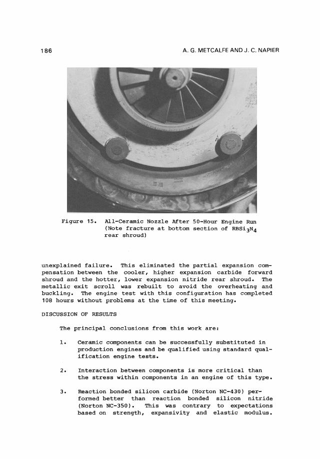
Figure 15. AlI-Cerarnic Nozzle After 50-Hour Engine Run (Note fracture at bottom section of RBSi3N4 rear shroud)
unexplained failure. This eliminated the partial expansion compensation between the cooler, higher expansion carbide forward shroud and the hotter, lower expansion nitride rear shroud. The metallic exit sc roll was rebuilt to avoid the overheating and buckling. The engine test with this configuration has completed 108 hours without problems at the time of this meeting.
DISCUSSION OF RESULTS
The principal conclusions from this work are:
1. Cerarnic components can be successfully substituted in production engines and be qualified using standard qualification engine tests.
2. Interaction between components is more critical than the stress within components in an engine of this type.
3. Reaction bonded silicon carbide (Norton NC-430) perforrned better than reaction bonded silicon nitride (Norton NC-350). This was contrary to expectations based on strength, expansivity and elastic modulus.


![Current Technology if Radial-Inflow Turbines fir Compressible ...the "Pelton," "Francis," and "Kaplan" [4]. Pelton turbines have a special geometry which has no true counterpart in](https://img.pdfslide.us/doc/110x75/6099c308eda602790f724e3b/current-technology-if-radial-inflow-turbines-fir-compressible-the-pelton.jpg)