Embed Size (px)
Citation preview

Product
Ceramic Capacitors:High Q High RF Power
High Temperature High Voltage
AFM MICROELECTRONICS INC
WWW.AFMMICROELECTRONICS.COM

Company Overview 4
Product Overveiw 5
High Frequency Capacitors - MPR,MNR, MXR Series
MPR11 - RF/ Microwave Porcelain Multilayer Capacitors size 0505 6
MPR12 - RF/ Microwave Porcelain Multilayer Capacitors size 1111 10
MNR11 - RF/ Microwave COG (NPO) Multilayer Capacitors size 0505 16
MNR12 - RF/ Microwave COG (NPO) Multilayer Capacitors size 1111 20
MNR02 - RF/ Microwave COG (NPO) Multilayer Capacitors size 0402 25
MNR03 - RF/ Microwave COG (NPO) Multilayer Capacitors size 0603 27
MNR05 - RF/ Microwave COG (NPO) Multilayer Capacitors size 0805 31
MXR11 - High Capacitance X7R Multilayer Ceramic Capacitors Size 0505 35
MXR12 - High Capacitance X7R Multilayer Ceramic Capacitors Size 1111 37
Termination Options 39
Lead Options 42
Engineering Kits Information 43
Highpower Capacitors - MPH, MNH Series
MPH Overview - High Power, High Current Capacitors 44
MPH25 - High Power, High Current RF Porcelain Multilayer Capacitors size 2325 46
MPH1 - High Power, High Current Capacitors size 3838 51
MPH2 - High Power, High Current Capacitors size 7638 56
MPH3 - High Power, High Current Capacitors size 7676 58
MNH25 - High Power, High Current Capacitors size 2325 60
MNH1 - High Power, High Current Capacitors size 3838 65
High Temperature Multilayer Ceramic Capacitors
HNT - High Temperature 200°C “T” Series Axial and Radial Leaded C0G (NP0) Capacitors 70
HXT - High Temperature 200°C “T” Series Axial and Radial Leaded X7R Capacitors 73
MNT11 - High Temperature 200°C “T” Series COG (NPO) RF/Microwave Multilayer Capacitors size 0505 76
MNT12 - High Temperature 200°C “T” Series COG (NPO) RF/Microwave Multilayer Capacitors size 1111 79
MPT12 - High Temperature 200°C “T” Series Porcelain RF/Microwave Multilayer Capacitors size 1111 82
HPT12 - High Temperature 200°C “T” Series Porcelain Radial and Axial Leaded Capacitors size 1111 85
Contents

High Voltage Multilayer Ceramic Capacitors
SNT/SXT - High Voltage, 200°C “T” Series DC COG (NPO)/X7R Ceramic Chip Surface Mount Capacitors 87
VNT/VXT - High Voltage, High Temperature 200°C “T” Series Radial Leaded COG (NPO)/X7R Capacitors 91
SNR/SXR - High Voltage, High Reliability DC COG (NPO)/X7R Chip Capacitors 96
VNR/VXR - High Voltage, High Reliability DC COG (NPO)/X7R Ceramic Chip Capacitors 100
VNC - High Voltage, COG (NPO) Radial Leaded Multilayer Ceramic Capacitors 104
VXC - High Voltage, X7R Radial Leaded Multilayer Ceramic Capacitors 106
VNM/VRM/VZM - High Voltage, MIL-PRF-49467 Equivalent Radial Leaded Multilayer Ceramic Capacitors 108
GBBL Substrate 111
Dielectric Powder 112
200C-ULF Powder 113
252X-ULF Powder 114
Cross Reference 115
High Reliability Multilayer Ceramic Capacitor Protocols 117
Useful Capacitor Formulas 120
Metric Prefixes & Symbols 121
Equipments 122
Contents

4AFM Microelectronics Inc
Phone (858)755-7688 • Fax (858)348-3217 • 3347 Industrial Court • Suite J • San Diego, CA 92121 USAwww.afmmicroelectronics.com
American Function Materials Inc (AFM Inc) founded at Alhambra, California in 2002, is now located at in San
Diego California.
AFM designs, develops, manufactures and markets RF/microwave Multilayer Capacitors, High Power High
current Multilayer Capacitors, High Temperature High Voltage Multilayer Capacitors, GBBL(Grain Boundary
Barrier Layer), High K substrates for Single Layer Capacitors, Ultra Low Fire Dielectric powder for multilayer
capacitors. Capacitors produced range in size from 0505 to 13560, with operating voltages from 25 volts to 50,000
volts. The AFM capacitors find wide use in the wireless communications infrastructure, fiber optic, medical
electronics, and semiconductor manufacturing equipment, defense, aerospace, and satellite communications
markets.
AFM operates a state of the art multilayer ceramic capacitor (MLCC), manufacturing line including ceramic slip
casting, automated tight-tolerance printing-stacking, iso-static pressing, automated termination, automated test
and sorting process, and plating process.
AFM has a full complement of test tools:
T.C.C. Test System,
Particle analyzer,
Thin film sputter
High frequency Q and ESR test system.
The AFM engineering team has been working in the ceramic capacitor industry more than 25 years. They have
accumulated the comprehensive knowledge of the technology involved in manufacturing electronic ceramics,
from formulation and processing to environment conditioning, life testing, product burn-in, acceleration and
etc.
AFM capacitors with their competitive price and their short lead times are an exceptional value in today’s
electronic market place. In addition to the AFM standard capacitor products AFM is also interested in pursuing
custom capacitor designs and will work with customers to develop special products in electronic ceramics.
For more information visit our website at www.afmmicroelectronics.com
Company Overview

5AFM Microelectronics Inc
Phone (858)755-7688 • Fax (858)348-3217 • 3347 Industrial Court • Suite J • San Diego, CA 92121 USAwww.afmmicroelectronics.com
Dielectrics Substrate and Low Fired Powder
• RF/UHF/Microwave Capacitors • Porcelain Capacitors • Medium and High Power High Frequency Capacitors • Non Magnetic Fixed Capacitors for Medical Imaging Equipment • Multilayer Ceramic Capacitors for RF and Microwave
Product Overview
. Dielectric substrate is Grain Boundary Layer (GBL) material, which equal to AVX’s MAXI material has highest dielectric constant in ceramic capacitor industry. Because of the low insert loss of GBL material at high frequency, it has been used in microwave device such as microwave amplifier, microwave module, IC package, blue tooth module and communication module etc.
Dielectric ceramic powder is Ultra Low fired material that can be fired at lower then 920oC. This low fired temperature allows manufacture to use low cost electrode system such as 95Ag/5Pd or 100% Silver to make Multilayer Ceramic Capacitor (MLCC). The ceramic powder includes COG and X7R formulation. The COG formulation has high Q at high frequency and can be used for making MLCC of cellular phone and other high frequency applications.
• High Temperature Multilayer Ceramic Capacitors (“T” Series) • RF/Microwave (200°C) Chip and Leaded Capacitors • High Temperature (200°C) Multilayer Ceramic Chip Capacitors • High Temperature(200°C) Leaded Capacitors, X7R & NPO • High Temperature, High Voltage (500V to 5000V) Leaded Capacitors
AFM has the most advanced test, and diagnostic equipment available for test and diagnostic material characterization and component electrical characteristics. The ability of our combined technical staff is unsurpassed.
Multilayer Capacitors
• High Voltage Capacitors • High Voltage Surface Mount Chip Capacitors • High Voltage Leaded Capacitors • High Temperature, High Voltage Leaded Capacitors

6AFM Microelectronics Inc
Phone (858)755-7688 • Fax (858)348-3217 • 3347 Industrial Court • Suite J • San Diego, CA 92121 USAwww.afmmicroelectronics.com
MPR 11RF/Microwave Porcelain Multilayer Capacitors
AFM Part Number Code
Applications
Typical Functional Applications: Bypass, Coupling, Tuning, Feedback, Impedance Matching and DC Blocking in circuits such as RF amplifiers, filters and timing circuits.
M W11RP EJ101 BB
Product Series:M: High Frequency
Dielectrics:P: Porcelain
Product Type:R: Chip
Chip Size:11: 0505
Termination Code:C: Pd/Ag TermG: Ag Term, Ni/Au PlatedN: Non Magnetic Term (Ag Term, Cu/Sn Plated)P: Solder Dipped W Term in 60/40 Sn/PbT: Ag Term, Ni/100% Sn Plated (Pb Free)W: Ag Term, Ni Barrier, 90/10 Sn/Pb Plated
Capacitance Code:1st two digits are significant: Third digit denotes number of zero(s); R=Decimal point 2R0=2.0pF101=100pF
Tolerance:B: ±0.1pFC: ±0.25pFD: ±0.5pFF: ±1%G: ±2%J: ±5%K: ±10%M: ±20%
Voltage:E: 150 VdcF: 200 VdcG: 250 Vdc
Marking:B: Not MarkedM: Marked (Cap code and tolerance)S: Special Marking
Packaging:B: BulkT: Tape & ReelW: Waffle Pack
C
Test Code:C: Commercial Test
S: Special (Customer Defined)
M: Hi-Rel
• Capacitance Range: 0.1pF to 100pF
• High Q Low ESR/ESL
• High Power
• Ultra Stable Performance
• High Self-Resonance
• Operating Voltages
- DC Voltage: 150V
• Extended WVDC up to 250VDC
Features

7AFM Microelectronics Inc
Phone (858)755-7688 • Fax (858)348-3217 • 3347 Industrial Court • Suite J • San Diego, CA 92121 USAwww.afmmicroelectronics.com
MPR 11
CAPCODE
CAP (pF)
TOL RATED WVdc
CAPCODE
CAP (pF)
TOL RATED WVdc
CAPCODE
CAP (pF)
TOL RATED WVdc
CAPCODE
CAP (pF)
TOL RATED WVdc
STD.* EXT.* STD. EXT. STD. EXT. STD. EXT.
0R1 0.1B
150 250
1R7 1.7
B, C, D 150 250
6R2 6.2 B, C, D
150 250
270 27
F, G, J, K, M 150
250
0R2 0.2 1R8 1.8 6R8 6.8
B, C, J, K, M
300 300R3 0.3
B, C1R9 1.9 7R5 7.5 330 33
0R4 0.4 2R0 2.0 8R2 8.2 360 360R5 0.5
B, C, D
2R1 2.1 9R1 9.1 390 390R6 0.6 2R2 2.2 100 10
F, G, J, K, M
430 430R7 0.7 2R4 2.4 110 11 470 470R8 0.8 2R7 2.7 120 12 510 510R9 0.9 3R0 3.0 130 13 560 561R0 1.0 3R3 3.3 150 15 620 62
200
1R1 1.1 3R6 3.6 160 16 680 68
1R2 1.2 3R9 3.9 180 18 750 75
1R3 1.3 4R3 4.3 200 20 820 82
1R4 1.4 4R7 4.7 220 22 910 91
1R5 1.5 5R1 5.1 240 24 101 100
1R6 1.6 5R6 5.6
RF/Microwave Porcelain Multilayer Capacitors
AFM Series
TermCode Type MIL-
PRF-55681 Outlines
Body DimensionsInches (mm)
Lead and TerminationDimensions and Materials
Length(L)
Width (W)
Thickness(T) B Materials
MPR11
W Solder Plate CDR12BG
.055+.015-.010
(1.40+0.38-0.25)
.055±.015(1.4±0.38)
.057 (1.45)max
.015 (0.38)±.010 (0.25)max
Solder Plated Over Nickel Barrier Termination90 Sn/ 10 Pb
P Pellet CDR12BG W Termination with Sn/Pb Solder Dip
T Lead FreeSolder Plated
N/A
Lead-Free and RoHS Compliant
Tin Plated Over Nickel Barrier Termination
G Gold Plated CDR11BG
Lead-Free and RoHS Compliant
Gold Plated Over Nickel BarrierTermination
C Pd/Ag CDR11BG Palladium/Silver Termination
NNon Magnetic
Term.(Ag Term, Cu/Sn Plated
N/A Cu/Sn Plated Over Silver Termination
Chip Dimensions and Termination Options
W
B
L
T
*STD.:Standard Voltage; EXT.: Extended VoltageStandard Capacitance Values

8AFM Microelectronics Inc
Phone (858)755-7688 • Fax (858)348-3217 • 3347 Industrial Court • Suite J • San Diego, CA 92121 USAwww.afmmicroelectronics.com
Specification and Performance
MPR 11RF/Microwave Porcelain Multilayer Capacitors
Piezoelectric and Aging Effect: None
Temperature Range: -55°C to +125°C
Temperature Coefficient of Capacitance( TCC): +90±20ppm/°C (-55°C to +125°C)
Quality Factor (Q) : >10,000 at 1MHz
Insulation Resistance (IR, at Rated Voltage):0.1pF~100pF: 106MΩ min. at +25°C at rated WVDC 105MΩ min. at +125°C at rated WVDC
Dielectric Withstand Voltage (DWV): 250% of rated WVDC for 5 secs
Capacitance Drift: ±0.02% or ±0.02pF, whichever is greater
Environmental Tests
Item Specifications Method
Thermal Shock DWV: the initial valueIR: shall be not less than 30% the initial valueCapacitance Change: no more than 0.5% or 0.5pF
MIL-STD-202, Method 107, Condition A.
At the maximum rated temperature (-55°C and +125°C) stay 30
minutes, the time of removing shall be not more than 3 minutes.
Perform the five cycles.
Moisture Resistance
MIL-STD-202, Method 106
Humidity (steady state)
DWV: the initial valueIR: the initial valueCapacitance Change: no more than 0.3% or 0.3pF
MIL-STD-202, Method 103, Condition A, with 1.5 volts D.C.
applied while subjected to an environment of 85°C with 85%
relative humidity for 240 hours min.
LifeIR: shall be not less than 30% the initial valueCapacitance Change: no more than 0.2%
MIL-STD-202, Method 108, for 2000 hours, at 125°C.
200% Rated Voltage D.C. applied.
MPR11 Series Capacitors are designed and manufactured to meet and exceed the requirements of EIA-198, MIL-PRF-55681 and MIL-PRF-123.

9AFM Microelectronics Inc
Phone (858)755-7688 • Fax (858)348-3217 • 3347 Industrial Court • Suite J • San Diego, CA 92121 USAwww.afmmicroelectronics.com
ESR vs. Capacitance Q vs. Capacitance
Resonance Current Rating vs. Capacitance
Performance Curve
MPR 11RF/Microwave Porcelain Multilayer Capacitors

10AFM Microelectronics Inc
Phone (858)755-7688 • Fax (858)348-3217 • 3347 Industrial Court • Suite J • San Diego, CA 92121 USAwww.afmmicroelectronics.com
MPR 12
AFM Part Number Code
Typical Functional Applications: Bypass, Coupling, Tuning, Feedback, Impedance Matching and DC Blocking in Circuits Such as RF Amplifiers, Filters and Timing Circuits.
M W12RP BJ101 BB
Product Series:M: High Frequency
Dielectrics:P: Porcelain
Product Type:R: Chip
Chip Size:12: 1111
Capacitance Code:1st two digits are signifi-cant: Third digit denotes number of zero(s); R=Decimal point 2R0=2.0pF101=100pF
Tolerance:B: ±0.1pFC: ±0.25pFD: ±0.5pFF: ±1%G: ±2%J: ±5%K: ±10%M: ±20%
Voltage:B: 50 VdcD: 100 VdcF: 200 VdcH: 300 VdcJ: 500 VdcL: 1000VdcN:1500VdcP: 2500Vdc
Marking:B: Not MarkedM: Marked (Cap code and tolerance)S: Special Marking
Packaging:B: BulkT: Tape & ReelW: Waffle Pack
RF/Microwave Porcelain Multilayer Capacitors
C
Test Code:C: Commercial Test
S: Special (Customer Defined)
M: Hi-Rel
Applications
• Capacitance Range: 0.1pF to 1000pF
• High Q Low ESR/ESL
• High Power
• Ultra Stable Performance
• High Self-Resonance
• Operating Voltages
- DC Voltage: 50V to 500V
• Extended WVDC up to 1500VDC
Features
Termination Code:A: Axial Wire;AN: Non-Mag Axial WireB: Axial RibbonBN: Non-Mag Axial RibbonC: Pd/Ag TermG: Ag Term, Ni/Au PlatedM: MicrostripMN: Non-Mag MicrostripN: Non Magnetic Term(Ag Term., Cu/Sn Plated)P: Solder Dipped W Term in 60/40 Sn/PbQ: Radial WireQN: Non-Mag Radial WireT: Ag Term, Ni/100% Sn Plated (Pb Free)W: Ag Term, Ni Barrier, 90/10 Sn/Pb Plated

11AFM Microelectronics Inc
Phone (858)755-7688 • Fax (858)348-3217 • 3347 Industrial Court • Suite J • San Diego, CA 92121 USAwww.afmmicroelectronics.com
TermCode Type MIL-
PRF-55681 Outlines
Body DimensionsInches (mm)
Lead and TerminationDimensions and Materials
Length(L) Width (W) Thickness
(T) B Materials
W Solder Plate CDR14BG
.110+.020-.010
(2.79+0.51-0.25)
.110±.015(2.79±0.38)
.102 (2.59)max
.015 (0.38)±.010 (0.25)max
Solder Plated Over Nickel Barrier Termination90 Sn/10 Pb
P Pellet CDR14BG
.110+.035-.010
(2.79+0.89-0.25)
.110±.015(2.79±0.38)
W Termination with Sn/Pb Solder Dip
T Lead FreeSolder Plated
N/A
.110+.020-.010
(2.79+0.51-0.25)
.110±.015(2.79±0.38)
Lead-Free and RoHS Compliant
Tin Plated Over Nickel Barrier Termination
G Gold Plated CDR13BG
Lead-Free and RoHS Compliant
Gold Plated Over Nickel BarrierTermination
C Pd/Ag CDR13BG Palladium/Silver Termination
N Non Magnetic Term.(Ag Term, Cu/Sn Plated) N/A Cu/Sn Plated Over
Silver Termination
Length(LL)
Width(WL)
Thickness(TL)
A/AN
Axial Wire/Non-Magnetic
CDR25BG
.145±.020(3.68±0.51)
.110±.015(2.79±0.38)
.102(2.59)max.
..500(12.7)min.
#26 AWG.,.016(.406) dia.
nominal
Q/QN
Radial Wire/Non-Magnetic
CDR23BG
M/MN
Microstrip/Non-Magnetic
CDR21GB
.135±.015(3.43±0.38)
.120(3.05)max.
..250inches(6.35mm)min.
.093±.0 05inches(2.36
±.0 13mm)
.004±.0 01inches(0.102
±.0.025mm)
B/BN
Axial Ribbon/Non-Magnetic
CDR22BG
102(2.59)max.
R
Radial Ribbon
CDR24BG
Chip Dimensions and Termination Options
W
B
L
T
MPR 12RF/Microwave Porcelain Multilayer Capacitors

12AFM Microelectronics Inc
Phone (858)755-7688 • Fax (858)348-3217 • 3347 Industrial Court • Suite J • San Diego, CA 92121 USAwww.afmmicroelectronics.com
Standard Capacitance Values
MPR 12RF/Microwave Porcelain Multilayer Capacitors
CAPCODE
CAP (pF) TOL
RATED WVdc CAPCODE
CAP (pF) TOL
RATED WVdc CAPCODE
CAP (pF) TOL
RATED WVdc CAP
CODECAP (pF) TOL
RATED WVdc
STD.* EXT.* STD. EXT. STD. EXT. STD. EXT.
0R1 0.1B
500 1500
2R4 2.4
B, C, D
500 1500
200 20
F, G, J, K, M
500 1500
151 150
F, G, J, K, M
300 10000R2 0.2 2R7 2.7 220 22 161 1600R3 0.3
B, C3R0 3.0 240 24 181 180
0R4 0.4 3R3 3.3 270 27 201 2000R5 0.5
B, C, D
3R6 3.6 300 30 221 220
200
N/A
0R6 0.6 3R9 3.9 330 33 241 2400R7 0.7 4R3 4.3 360 36 271 2700R8 0.8 4R7 4.7 390 39 301 3000R9 0.9 5R1 5.1 430 43 331 3301R0 1.0 5R6 5.6 470 47 361 3601R1 1.1 6R2 6.2 510 51
500
1000
391 3901R2 1.2 6R8 6.8
B, C, J, K, M
560 56 431 4301R3 1.3 7R5 7.5 620 62 471 4701R4 1.4 8R2 8.2 680 68 511 510
1001R5 1.5 9R1 9.1 750 75 561 5601R6 1.6 100 10
F, G, J, K, M
820 82 621 620
1R7 1.7 110 11 910 91 681 680
50
1R8 1.8 120 12 101 100 751 7501R9 1.9 130 13 111 110
300
821 8202R0 2.0 150 15 121 120 911 9102R1 2.1 160 16 131 130 102 10002R2 2.2 180 18
*STD.:Standard Voltage; EXT.: Extended Voltage
Specification and PerformancePiezoelectric and Aging Effect: None
Temperature Range: 0.1pF~330pF: -55°C to +175°C360pF~1000pF: -55°C to +125°C
Temperature Coefficient of Capacitance( TCC):+90±20ppm/°C (-55°C to +125°C)+90±30ppm/°C (125°C to +175°C)
Quality Factor (Q) : >10,000 at 1MHz
Insulation Resistance (IR, at Rated Voltage):
0.1pF~470pF: 106MΩ min. at +25°C at rated WVDC 105MΩ min. at +125°C at rated WVDC510pF~1000pF:105MΩ min. at +25°C at rated WVDC 104MΩ min. at +125°C at rated WVDC
Dielectric Withstand Voltage (DWV): 250% of rated WVDC for 5 secs
Capacitance Drift: ±0.02% or ±0.02pF, whichever is greater

13AFM Microelectronics Inc
Phone (858)755-7688 • Fax (858)348-3217 • 3347 Industrial Court • Suite J • San Diego, CA 92121 USAwww.afmmicroelectronics.com
MPR 12RF/Microwave Porcelain Multilayer Capacitors
Environmental Tests
Item Specifications Method
Thermal ShockDWV: the initial valueIR: shall be not less than 30% the initial valueCapacitance Change: no more than 0.5% or 0.5pF
MIL-STD-202, Method 107, Condition A.
At the maximum rated temperature (-55°C and +125°C) stay 30
minutes, the time of removing shall be not more than 3 minutes.
Perform the five cycles.
Moisture Resistance MIL-STD-202, Method 106
Humidity (steady state)
DWV: the initial valueIR: the initial valueCapacitance Change: no more than 0.3% or 0.3pF
MIL-STD-202, Method 103, Condition A, with 1.5 volts D.C.
applied while subjected to an environment of 85°C with 85%
relative humidity for 240 hours min.
LifeIR: shall be not less than 30% the initial valueCapacitance Change: no more than 0.2%
MIL-STD-202, Method 108, for 2000 hours, at 125°C.
Rated voltage≤500V: 200% Rated Voltage D.C. applied.
500V≤Rated Voltage≤1250V: 120% Rated Volatge D.C. applied.
Rated voltage >1250V: 100% Rated Voltage D.C. applied.
MPR12 Series Capacitors are designed and manufactured to meet and exceed the requirements of EIA-198, MIL-PRF-55681 and MIL-PRF-123.

14AFM Microelectronics Inc
Phone (858)755-7688 • Fax (858)348-3217 • 3347 Industrial Court • Suite J • San Diego, CA 92121 USAwww.afmmicroelectronics.com
MPR 12RF/Microwave Porcelain Multilayer Capacitors
ESR vs.Capacitance ESR vs.Capacitance
Performance Curve
Q vs.Capacitance Q vs.Capacitance

15AFM Microelectronics Inc
Phone (858)755-7688 • Fax (858)348-3217 • 3347 Industrial Court • Suite J • San Diego, CA 92121 USAwww.afmmicroelectronics.com
Resonance vs.Capacitance
Current Rating vs. Capacitance
MPR 12RF/Microwave Porcelain Multilayer Capacitors
Current Rating vs. Capacitance
Performance Curve
16AFM Microelectronics Inc
Phone (858)755-7688 • Fax (858)348-3217 • 3347 Industrial Court • Suite J • San Diego, CA 92121 USAwww.afmmicroelectronics.com
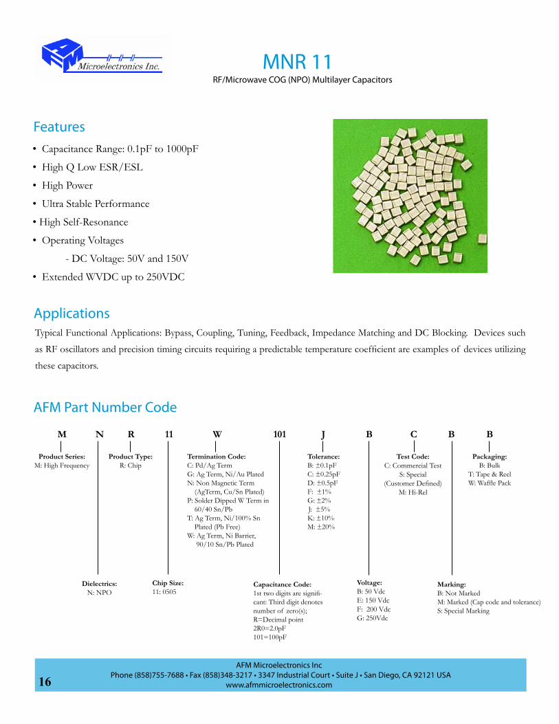
MNR 11RF/Microwave COG (NPO) Multilayer Capacitors
AFM Part Number Code
Typical Functional Applications: Bypass, Coupling, Tuning, Feedback, Impedance Matching and DC Blocking. Devices such
as RF oscillators and precision timing circuits requiring a predictable temperature coefficient are examples of devices utilizing
these capacitors.
M W11RN BJ101 BB
Product Series:M: High Frequency
Dielectrics:N: NPO
Product Type:R: Chip
Chip Size:11: 0505
Termination Code:C: Pd/Ag TermG: Ag Term, Ni/Au PlatedN: Non Magnetic Term (AgTerm, Cu/Sn Plated)P: Solder Dipped W Term in 60/40 Sn/PbT: Ag Term, Ni/100% Sn Plated (Pb Free)W: Ag Term, Ni Barrier, 90/10 Sn/Pb Plated
Capacitance Code:1st two digits are signifi-cant: Third digit denotes number of zero(s); R=Decimal point 2R0=2.0pF101=100pF
Tolerance:B: ±0.1pFC: ±0.25pFD: ±0.5pFF: ±1%G: ±2% J: ±5%K: ±10%M: ±20%
Voltage:B: 50 VdcE: 150 VdcF: 200 VdcG: 250Vdc
Marking:B: Not MarkedM: Marked (Cap code and tolerance)S: Special Marking
Packaging:B: Bulk
T: Tape & ReelW: Waffle Pack
C
Test Code:C: Commercial Test
S: Special (Customer Defined)
M: Hi-Rel
Applications
• Capacitance Range: 0.1pF to 1000pF
• High Q Low ESR/ESL
• High Power
• Ultra Stable Performance
• High Self-Resonance
• Operating Voltages
- DC Voltage: 50V and 150V
• Extended WVDC up to 250VDC
Features
17AFM Microelectronics Inc
Phone (858)755-7688 • Fax (858)348-3217 • 3347 Industrial Court • Suite J • San Diego, CA 92121 USAwww.afmmicroelectronics.com
CAPCODE
CAP (pF) TOL
RATED WVdc CAP-
CODECAP (pF) TOL
RATED WVdc CAP
CODECAP (pF) TOL
RATED WVdc CAP
CODECAP (pF) TOL
RATED WVdc
STD.* EXT.* STD. EXT. STD. EXT. STD. EXT.
0R1 0.1B
150 250
2R4 2.4
B, C, D
150 250
200 20
F, G, J, K, M
150
250
151 150
F, G, J, K, M
150
N/A
0R2 0.2 2R7 2.7 220 22 161 1600R3 0.3
B, C3R0 3.0 240 24 181 180
0R4 0.4 3R3 3.3 270 27 201 2000R5 0.5
B, C, D
3R6 3.6 300 30 221 2200R6 0.6 3R9 3.9 330 33 241 2400R7 0.7 4R3 4.3 360 36 271 2700R8 0.8 4R7 4.7 390 39 301 3000R9 0.9 5R1 5.1 430 43 331 3301R0 1.0 5R6 5.6 470 47 361 3601R1 1.1 6R2 6.2 510 51 391 3901R2 1.2 6R8 6.8 560 56 431 4301R3 1.3 7R5 7.5 620 62
200
471 4701R4 1.4 8R2 8.2 B, C,
J, K, M
680 68 511 5101R5 1.5 9R1 9.1 750 75 561 5601R6 1.6 100 10 820 82 621 620
1R7 1.7 110 11
F, G, J, K, M
910 91 681 680
50
1R8 1.8 120 12 101 100 751 7501R9 1.9 130 13 111 110
N/A
821 8202R0 2.0 150 15 121 120 911 9102R1 2.1 160 16 131 130 102 10002R2 2.2 180 18
Standard Capacitance Values
Capacitance (pF) Temperature (°C)
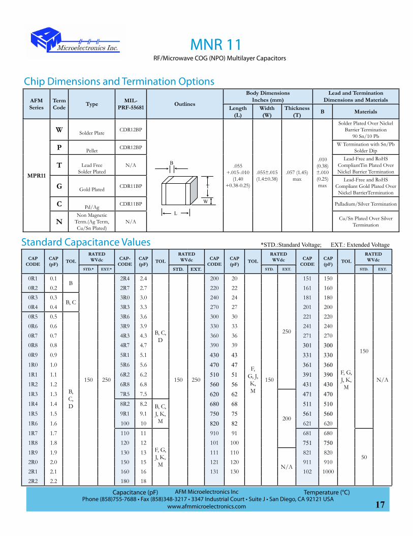
MNR 11RF/Microwave COG (NPO) Multilayer Capacitors
AFM Series
TermCode Type MIL-
PRF-55681 Outlines
Body DimensionsInches (mm)
Lead and TerminationDimensions and Materials
Length(L)
Width (W)
Thickness(T) B Materials
MPR11
W Solder Plate CDR12BP
.055+.015-.010
(1.40+0.38-0.25)
.055±.015(1.4±0.38)
.057 (1.45)max
.010 (0.38)±.010 (0.25)max
Solder Plated Over Nickel Barrier Termination
90 Sn/10 Pb
P Pellet CDR12BP W Termination with Sn/Pb Solder Dip
T Lead FreeSolder Plated
N/ALead-Free and RoHS
CompliantTin Plated Over Nickel Barrier Termination
G Gold Plated CDR11BPLead-Free and RoHS
Compliant Gold Plated Over Nickel BarrierTermination
C Pd/Ag CDR11BP Palladium/Silver Termination
NNon Magnetic
Term.(Ag Term, Cu/Sn Plated)
N/A Cu/Sn Plated Over Silver Termination
Chip Dimensions and Termination Options
W
B
L
T
*STD.:Standard Voltage; EXT.: Extended Voltage

18AFM Microelectronics Inc
Phone (858)755-7688 • Fax (858)348-3217 • 3347 Industrial Court • Suite J • San Diego, CA 92121 USAwww.afmmicroelectronics.com
Specification and Performance
MNR 11RF/Microwave COG (NPO) Multilayer Capacitors
Piezoelectric and Aging Effect: None
Temperature Range: -55°C to +125°C
Temperature Coefficient of Capacitance: 0±30ppm/°C
Quality Factor (Q) :>10,000 (0.1pF~100pF) at 1MHz>2000 (110pF~1000pF) at 1MHz
Insulation Resistance (IR, at Rated Voltage):
0.1pF~470pF: 106MΩ min. at +25°C at rated WVDC 105MΩ min. at +125°C at rated WVDC510pF~1000pF:105MΩ min. at +25°C at rated WVDC 104MΩ min. at +125°C at rated WVDC
Dielectric Withstand Voltage (DWV): 250% of rated WVDC for 5 secs
Capacitance Drift: ±0.02% or ±0.02pF, whichever is greater
Environmental Tests
Item Specifications Method
Thermal Shock DWV: the initial valueIR: shall be not less than 30% the initial valueCapacitance Change: no more than 0.5% or 0.5pF
MIL-STD-202, Method 107, Condition A.
At the maximum rated temperature (-55°C and +125°C) stay 30
minutes, the time of removing shall be not more than 3 minutes.
Perform the five cycles.
Moisture Resistance
MIL-STD-202, Method 106
Humidity (steady state)
DWV: the initial valueIR: the initial valueCapacitance Change: no more than 0.3% or 0.3pF
MIL-STD-202, Method 103, Condition A, with 1.5 volts D.C.
applied while subjected to an environment of 85°C with 85%
relative humidity for 240 hours min.
LifeIR: shall be not less than 30% the initial valueCapacitance Change: no more than 0.2%
MIL-STD-202, Method 108, for 2000 hours, at 125°C.
200% Rated Voltage D.C. applied.
MNR11 Series Capacitors are designed and manufactured to meet and exceed the requirements of EIA-198, MIL-PRF-55681 and MIL-PRF-123.
19AFM Microelectronics Inc
Phone (858)755-7688 • Fax (858)348-3217 • 3347 Industrial Court • Suite J • San Diego, CA 92121 USAwww.afmmicroelectronics.com
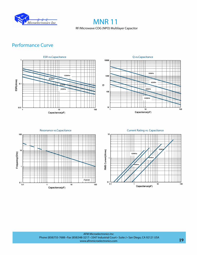
ESR vs.Capacitance Q vs.Capacitance
Resonance vs.Capacitance Current Rating vs. Capacitance
Performance Curve
MNR 11RF/Microwave COG (NPO) Multilayer Capacitor

20AFM Microelectronics Inc
Phone (858)755-7688 • Fax (858)348-3217 • 3347 Industrial Court • Suite J • San Diego, CA 92121 USAwww.afmmicroelectronics.com
Typical Functional Applications: Bypass, Coupling, Tuning, Feedback, Impedance Matching and DC Blocking. Devices such as RF oscillators and precision timing circuits requiring a predictable temperature coefficient are examples of devices utilizing these capacitors.
M W12RN BJ101 BB
Product Series:M: High Frequency
Dielectrics:N: NPO
Product Type:R: Chip
Chip Size:12: 1111
Capacitance Code:1st two digits are signifi-cant: Third digit denotes number of zero(s); R=Decimal point 2R0=2.0pF101=100pF
Tolerance:B: ±0.1pFC: ±0.25pFD: ±0.5pFF: ±1%G: ±2%J: ±5%K: ±10%M: ±20%
Voltage:B: 50 VdcD: 100 VdcF: 200 VdcH: 300 VdcJ: 500 VdcL: 1000 VdcN:1500 Vdc
Marking:B: Not MarkedM: Marked (Cap code and tolerance)S: Special Marking
Packaging:B: Bulk
T: Tape & ReelW: Waffle Pack
AFM Part Number Code
C
Test Code:C: Commercial Test
S: Special (Customer Defined)
M: Hi-Rel
MNR 12RF/Microwave COG (NPO) Multilayer Capacitors
Applications
• Capacitance Range: 0.1pF to 5100pF
• High Q Low ESR/ESL
• High Power
• Ultra Stable Performance
• High Self-Resonance
• Operating Voltages
- DC Voltage: 50V to 500V
• Extended WVDC up to 1500 Vdc
• Available with Encapsulation Option
Features
Termination Code:A: Axial Wire;AN: Non-Mag Axial WireB: Axial RibbonBN: Non-Mag Axial RibbonC: Pd/Ag TermG: Ag Term, Ni/Au PlatedM: MicrostripMN: Non-Mag MicrostripN: Non Magnetic Term(Ag Term., Cu/Sn Plated)P: Solder Dipped W Term in 60/40 Sn/PbQ: Radial WireQN: Non-Mag Radial WireT: Ag Term, Ni/100% Sn Plated (Pb Free)W: Ag Term, Ni Barrier, 90/10 Sn/Pb Plated

21AFM Microelectronics Inc
Phone (858)755-7688 • Fax (858)348-3217 • 3347 Industrial Court • Suite J • San Diego, CA 92121 USAwww.afmmicroelectronics.com
CAPCODE
CAP (pF) TOL
RATED WVdc CAPCODE
CAP (pF) TOL
RATED WVdc CAPCODE
CAP (pF) TOL
RATED WVdc CAPCODE
CAP (pF) TOL
RATED WVdc
STD.* EXT.* STD. EXT. STD. EXT. STD. EXT.
0R1 0.1B
500 1500
3R3 3.3
B, C, D
500 1500
360 36
F, G, J, K, M
500
1500
391 390
F, G, J, K, M
200
N/A
0R2 0.2 3R6 3.6 390 39 431 430
0R3 0.3B, C
3R9 3.9 430 43 471 470
0R4 0.4 4R3 4.3 470 47 511 5101000R5 0.5
B, C, D
4R7 4.7 510 51
1000
561 5600R6 0.6 5R1 5.1 560 56 621 6200R7 0.7 5R6 5.6 620 62 681 680
50
0R8 0.8 6R2 6.2 680 68 751 7500R9 0.9 6R8 6.8
B, C, J, K, M
750 75 821 8201R0 1.0 7R5 7.5 820 82 911 9101R1 1.1 8R2 8.2 910 91 102 10001R2 1.2 9R1 9.1 101 100 112 11001R3 1.3 100 10
F, G, J, K, M
111 110
300
122 12001R4 1.4 110 11 121 120 152 15001R5 1.5 120 12 131 130 182 18001R6 1.6 130 13 151 150 222 22001R7 1.7 150 15 161 160 272 27001R8 1.8 160 16 181 180 302 30001R9 1.9 180 18 201 200 332 33002R0 2.0 200 20 221 220
200 N/A
392 39002R1 2.1 220 22 241 240 472 47002R2 2.2 240 24 271 270 512 51002R4 2.4 270 27 301 3002R7 2.7 300 30 331 3303R0 3.0 330 33 361 360
Standard Capacitance Values
MNR 12RF/Microwave COG (NPO) Multilayer Capacitors
*STD.:Standard Voltage; EXT.: Extended Voltage
AFM Series
TermCode Type MIL-
PRF-55681 OutlinesBody Dimensions
Inches (mm) Lead and Termination
Dimensions and MaterialsLength(L) Width(W) Thickness(T) B Materials
MNR12
W Solder Plate CDR14BP.110
+.020-.010(2.79
+0.51-0.25)
.110±.015(2.79±0.38)
.102 (2.59)max
.015 (0.38)±.010 (0.25)
max
Solder Plated Over Nickel Barrier Termination
90 Sn/10 Pb
P Pellet CDR14BP W Termination with Sn/Pb Solder Dip
T Lead FreeSolder Plated N/A
Lead-Free and RoHS CompliantTin Plated Over Nickel Barrier Termination
Length(LL) Width(WL) Thickness(TL)
Q/QN Radial Wire/
Non-Magnetic
CDR23BP .145±.020(3.68±0.51)
.500(12.7)min.
#26 AWG.,.016 (0.406) dia.
nominal
RRadial Ribbon
CDR24BP .135±.015(3.43±0.38)
.025 (6.35)min.
.093±.005(2.36±0.13)
.004±.001(0.102±0.25)
Chip Dimensions and Termination Options
W
B
L
T

22AFM Microelectronics Inc
Phone (858)755-7688 • Fax (858)348-3217 • 3347 Industrial Court • Suite J • San Diego, CA 92121 USAwww.afmmicroelectronics.com
Specification and Performance
MNR 12RF/Microwave COG (NPO) Multilayer Capacitors
Piezoelectric and Aging Effect: None
Temperature Range: -55°C to +125°C
Temperature Coefficient of Capacitance: 0±30ppm/°C
Quality Factor (Q) :>10,000 (1pF~200pF) at 1MHz>2000 (220pF~1000pF) at 1MHz>2000 (1100pF~5100pF) at 1KHz
Insulation Resistance (IR, at Rated Voltage):
0.1pF~470pF:106MΩ min. at +25°C at rated WVDC105MΩ min. at +125°C at rated WVDC510pF~5100pF:105MΩ min. at +25°C at rated WVDC104MΩ min. at +125°C at rated WVDC
Dielectric Withstand Voltage (DWV): 250% of rated WVDC for 5 secs
Capacitance Drift: ±0.02% or ±0.02pF, whichever is greater
Environmental TestsMNR12 Series Capacitors are designed and manufactured to meet and exceed the requirements of EIA-198, MIL-PRF-55681 and MIL-PRF-123.
Item Specifications Method
Thermal Shock DWV: the initial valueIR: shall be not less than 30% the initial valueCapacitance Change: no more than 0.5% or 0.5pF
MIL-STD-202, Method 107, Condition A. At the maximum rated temperature (-55°C and +125°C) stay 30 minutes, the time of removing shall be not more than 3 minutes. Perform the five cycles.
Moisture Resistance
MIL-STD-202, Method 106
Humidity (steady state)
DWV: the initial valueIR: the initial valueCapacitance Change: no more than 0.3% or 0.3pF
MIL-STD-202, Method 103, Condition A, with 1.5 volts D.C. applied while subjected to an environment of 85°C with 85% relative humidity for 240 hours min.
Life IR: shall be not less than 30% the initial valueCapacitance Change: no more than 0.2%
MIL-STD-202, Method 108, for 2000 hours, at 125°C.Rated voltage≤500V: 200% Rated Voltage D.C. applied.500V≤Rated Voltage≤1250V: 120% Rated Volatge D.C. applied.Rated voltage >1250V: 100% Rated Voltage D.C. applied.
23AFM Microelectronics Inc
Phone (858)755-7688 • Fax (858)348-3217 • 3347 Industrial Court • Suite J • San Diego, CA 92121 USAwww.afmmicroelectronics.com
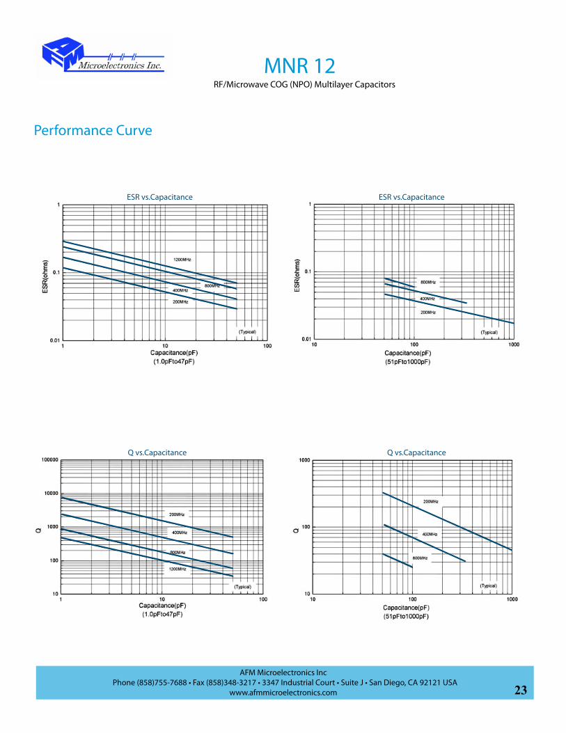
ESR vs.Capacitance ESR vs.Capacitance
Performance Curve
Q vs.Capacitance Q vs.Capacitance
MNR 12RF/Microwave COG (NPO) Multilayer Capacitors

24AFM Microelectronics Inc
Phone (858)755-7688 • Fax (858)348-3217 • 3347 Industrial Court • Suite J • San Diego, CA 92121 USAwww.afmmicroelectronics.com
MNR 12RF/Microwave COG (NPO) Multilayer Capacitors
Resonance vs.Capacitance
Current Rating vs.Capacitance Current Rating vs.Capacitance

25AFM Microelectronics Inc
Phone (858)755-7688 • Fax (858)348-3217 • 3347 Industrial Court • Suite J • San Diego, CA 92121 USAwww.afmmicroelectronics.com
MNR 02RF/Microwave COG (NPO) Multilayer Capacitors
AFM Part Number Code
Typical Functional Applications: Bypass, Coupling, Tuning, Feedback, Impedance Matching and DC Blocking. Devices such as RF oscillators and precision timing circuits requiring a predictable temperature coefficient are examples of devices utilizing these capacitors.
M W02RN FJ101 BB
Product Series:M: High Frequency
Dielectrics:N: NPO
Product Type:R: Chip
Chip Size:02: 0402
Termination Code:C: Pd/Ag TermT: Ag Term, Ni/100% Sn Plated (Pb Free)W: Ag Term, Ni Barrier, 90/10 Sn/Pb Plated
Capacitance Code:1st two digits are significant: Third digit denotes number of zero(s); R=Decimal point 2R0=2.0pF101=100pF
Tolerance:B: ± 0.1pFC: ± 0.25pFD: ±0.5pFF: ±1%G: ±2%J: ±5%K: ±10%M: ±20%
Voltage: F:200Vdc
Marking:B: Not Marked
Packaging:B: Bulk
T: Tape & ReelW: Waffle Pack
C
Test Code:C: Commercial Test
S: Special (Customer Defined)
M: Hi-Rel
Applications
• Capacitance Range: 0.1pF to 27pF
• High Q Low ESR/ESL
• High Power
• Ultra Stable Performance
• High Self-Resonance
• Operating Voltages
- DC Voltage: 250Vdc
Features

26AFM Microelectronics Inc
Phone (858)755-7688 • Fax (858)348-3217 • 3347 Industrial Court • Suite J • San Diego, CA 92121 USAwww.afmmicroelectronics.com
CAPCODE
CAP (pF) TOL RATED WVdc
CAP CODE
CAP (pF) TOL RATED WVdc
CAPCODE
CAP (pF) TOL RATED WVdc
0R1 0.1B
200
1R6 1.6
A, B, C, D 200
6R2 6.2 A, B, C, D
200
0R2 0.2 1R8 1.8 6R8 6.8
B, C, J, K0R3 0.3
A, B, C
2R0 2.0 7R5 7.5
0R4 0.4 2R2 2.2 8R2 8.2
0R5 0.5 2R4 2.4 9R1 9.10R6 0.6 2R7 2.7 100 10
F, G, J, K, M
0R7 0.7 3R0 3.0 110 11
0R8 0.8 3R3 3.3 120 120R9 0.9 3R6 3.6 150 151R0 1.0
A, B,C,D
3R9 3.9 180 181R1 1.1 4R3 4.3 200 201R2 1.2 4R7 4.7 220 221R3 1.3 5R1 5.1 240 241R5 1.5 5R6 5.6 270 27
Standard Capacitance Values
MNR 02RF/Microwave COG (NPO) Multilayer Capacitors
Chip DimensionsLength .040 ±.004in (1.02±0.1mm)
Width .020±.004in (0.51±0.1mm)
Thickness .024....+.005~-.003in (0.61....+0.13~-0.08mm)
Band .015in (0.38mm)
W
B
L
T
Specification and PerformancePiezoelectric and Aging Effect: None
Temperature Range: -55°C to +125°C
Temperature Coefficient of Capacitance: 0±30ppm/°C
Quality Factor (Q) : 2,000 min.
Insulation Resistance (IR, at Rated Voltage):105MΩ min. at +25°C at rated WVDC104MΩ min. at +125°C at rated WVDC
Dielectric Withstand Voltage (DWV): 250% of rated WVDC for 5 secs
Capacitance Drift: ±0.02% or ±0.02pF, whichever is greater

27AFM Microelectronics Inc
Phone (858)755-7688 • Fax (858)348-3217 • 3347 Industrial Court • Suite J • San Diego, CA 92121 USAwww.afmmicroelectronics.com
MNR 03RF/Microwave COG (NPO) Multilayer Capacitors
AFM Part Number Code
Typical Functional Applications: Bypass, Coupling, Tuning, Feedback, Impedance Matching and DC Blocking. Devices such as RF oscillators and precision timing circuits requiring a predictable temperature coefficient are examples of devices utilizing these capacitors.
M W03RN GJ101 BB
Product Series:M: High Frequency
Dielectrics:N: NPO
Product Type:R: Chip
Chip Size:03: 0603
Termination Code:C: Pd/Ag TermT: Ag Term, Ni/100% Sn Plated (Pb Free)W: Ag Term, Ni Barrier, 90/10 Sn/Pb Plated
Capacitance Code:1st two digits are signifi-cant: Third digit denotes number of zero(s); R=Decimal point 2R0=2.0pF101=100pF
Tolerance:B: ± 0.1pFC: ± 0.25pFD: ±0.5pFF: ±1%G: ±2%J: ±5%K: ±10%M: ±20%
Voltage:D: 100 VdcG: 250 Vdc
Marking:B: Not Marked
Packaging:B: Bulk
T: Tape & ReelW: Waffle Pack
C
Test Code:C: Commercial Test
S: Special (Customer Defined)
M: Hi-Rel
Applications
• Capacitance Range: 0.1pF to 100pF
• High Q Low ESR/ESL
• High Power
• Ultra Stable Performance
• High Self-Resonance
• Operating Voltages
- DC Voltage: 250Vdc
Features

28AFM Microelectronics Inc
Phone (858)755-7688 • Fax (858)348-3217 • 3347 Industrial Court • Suite J • San Diego, CA 92121 USAwww.afmmicroelectronics.com
CAPCODE
CAP (pF)
TOL RATED WVdc
CAP-CODE
CAP (pF)
TOL RATED WVdc
CAPCODE
CAP (pF)
TOL RATED WVdc
CAPCODE
CAP (pF)
TOL RATED WVdc
0R1 0.1
A, B, C, D 250
1R7 1.7
A, B, C, D 250
6R2 6.2 A,B,C,D
250
270 27
F, G, J, K, M 250
0R2 0.2 1R8 1.8 6R8 6.8
B, C, J, K,
300 300R3 0.3 1R9 1.9 7R5 7.5 330 330R4 0.4 2R0 2.0 8R2 8.2 360 360R5 0.5 2R1 2.1 9R1 9.1 390 390R6 0.6 2R2 2.2 100 10
F, G, J, K, M
430 430R7 0.7 2R4 2.4 110 11 470 470R8 0.8 2R7 2.7 120 12 510 510R9 0.9 3R0 3.0 130 13 560 561R0 1.0 3R3 3.3 150 15 620 621R1 1.1 3R6 3.6 160 16 680 681R2 1.2 3R9 3.9 180 18 750 751R3 1.3 4R3 4.3 200 20 820 821R4 1.4 4R7 4.7 220 22 910 911R5 1.5 5R1 5.1 240 24 101 100
1R6 1.6 5R6 5.6
Standard Capacitance Values
MNR 03RF/Microwave COG (NPO) Multilayer Capacitors
Chip DimensionsLength .063 ±.006in (1.60±0.15mm)
Width .032±.006in (0.81±0.15mm)
Thickness .030....+.005~-.003in (0.76....+0.13~-0.08mm)
Band .015in (0.38mm)
W
B
L
T
Specification and PerformancePiezoelectric and Aging Effect: None
Temperature Range: -55°C to +125°C
Temperature Coefficient of Capacitance: 0±30ppm/°C
Quality Factor (Q) : 2,000 min.
Insulation Resistance (IR, at Rated Voltage):105MΩ min. at +25°C at rated WVDC104MΩ min. at +125°C at rated WVDC
Dielectric Withstand Voltage (DWV): 250% of rated WVDC for 5 secs
Capacitance Drift: ±0.02% or ±0.02pF, whichever is greater

29AFM Microelectronics Inc
Phone (858)755-7688 • Fax (858)348-3217 • 3347 Industrial Court • Suite J • San Diego, CA 92121 USAwww.afmmicroelectronics.com
MNR 03RF/Microwave COG (NPO) Multilayer Capacitors
Environmental TestsMNR03 Series Capacitors are designed and manufactured to meet and exceed the requirements of EIA-198, MIL-PRF-55681 and MIL-PRF-123.
Item Specifications Method
Terminal Adhesion
Termination should not pull off, ceramic should remain undamaged.
Linear pull force exerted on axial leads soldered to each terminal 2.0lbs.
Resistance to soldering heat
No mechanical damgeCapacitance change: -1.0%~+2.0%Q>500I.R.>10G OhmsBreakdown voltage: 2.5 x WVDC
Preheat device to 150°C-180°C for 60 sec.Dip in 260°C±5°C solder for 10±1 sec.Measure after 24±2 hour cooling period
Thermal Shock
MIL-STD-202, Method 107, Condition A. At the maximum rated temperature (-55°C and +125°C) stay 30 minutes, the time of removing shall be not more than 3 minutes. Perform the five cycles.
Humidity (steady state)
No mechanical damgeCapacitance change: ±0.5% or 0.5pF max.Q>300I.R.>1G OhmsBreakdown voltage: 2.5 x WVDC
MIL-STD-202, Method 106
Low Voltage Humidity
No mechanical damgeCapacitance change: ±0.3% or 0.3pF max.Q>300I.R.>1G OhmsBreakdown voltage: 2.5 x WVDC
MIL-STD-202, Method 103, Condition A, with 1.5 volts D.C. applied while subjected to an environment of 85°C with 85% relative humidity for 240 hours min.
Life
No mechanical damgeCapacitance change: ±2.0% or 0.5pF max.Q>500I.R.>1G OhmsBreakdown voltage: 2.5 x WVDC
MIL-STD-202, Method 108, for 1000 hours, at 125°C.200% Rated Voltage D.C. applied.

30AFM Microelectronics Inc
Phone (858)755-7688 • Fax (858)348-3217 • 3347 Industrial Court • Suite J • San Diego, CA 92121 USAwww.afmmicroelectronics.com
MNR 03RF/Microwave C0G (NP0) Multilayer Capacitors
ESR vs.Capacitance
ESR vs. Frequency
Resonance vs.Capacitance
ESR vs. Frequency
Q vs.Capacitance Q vs. Frequency

31AFM Microelectronics Inc
Phone (858)755-7688 • Fax (858)348-3217 • 3347 Industrial Court • Suite J • San Diego, CA 92121 USAwww.afmmicroelectronics.com
MNR 05RF/Microwave COG (NPO) Multilayer Capacitors
AFM Part Number Code
Typical Functional Applications: Bypass, Coupling, Tuning, Feedback, Impedance Matching and DC Blocking. Devices such as RF oscillators and precision timing circuits requiring a predictable temperature coefficient are examples of devices utilizing these capacitors.
M W05RN FJ101 BB
Product Series:M: High Frequency
Dielectrics:N: NPO
Product Type:R: Chip
Chip Size:05:0805
Termination Code:C: Pd/Ag TermT: Ag Term, Ni/100% Sn Plated (Pb Free)W: Ag Term, Ni Barrier, 90/10 Sn/Pb Plated
Capacitance Code:1st two digits are significant: Third digit denotes number of zero(s); R=Decimal point 2R0=2.0pF101=100pF
Tolerance:B: ± 0.1pFC: ± 0.25pFD: ±0.5pFF: ±1%G: ±2%J: ±5%K: ±10%M: ±20%
Voltage:G: 250 Vdc
Marking:B: Not MarkedM: Marked (Cap code and tolerance)S: Special Marking
Packaging:B: Bulk
T: Tape & ReelW: Waffle Pack
C
Test Code:C: Commercial Test
S: Special (Customer Defined)
M: Hi-Rel
Applications
• Capacitance Range: 0.1pF to 240pF
• High Q Low ESR/ESL
• High Power
• Ultra Stable Performance
• High Self-Resonance
• Operating Voltages
- DC Voltage: 250Vdc
Features

32AFM Microelectronics Inc
Phone (858)755-7688 • Fax (858)348-3217 • 3347 Industrial Court • Suite J • San Diego, CA 92121 USAwww.afmmicroelectronics.com
CAPCODE
CAP (pF) TOL WVDCV
CAP CODE
CAP (pF) TOL WVDCV
CAPCODE
CAP (pF) TOL WVDCV
0R1 0.1A, B
250
3R3 3.3
B, C, D
250
300 30
F, G, J, K, M 250
0R2 0.2 3R6 3.6 330 330R3 0.3
A, B, C
3R9 3.9 360 360R4 0.4 4R3 4.3 390 390R5 0.5 4R7 4.7 430 430R6 0.6 5R1 5.1 470 470R7 0.7 5R6 5.6 510 510R8 0.8 6R2 6.2 560 560R9 0.9 6R8 6.8
B,C,J,K
620 621R0 1.0
A, B, C, D
7R5 7.5 680 681R1 1.1 8R2 8.2 750 751R2 1.2 9R1 9.1 820 821R3 1.3 100 10
F, G, J, K, M
910 911R5 1.5 110 11 101 1001R6 1.6 120 12 111 1101R8 1.8 150 15 121 1202R0 2.0 180 18 151 1502R2 2.2 200 20 181 1802R4 2.4 220 22 201 2002R7 2.7 240 24 221 2203R0 3.0 270 27 241 240
Standard Capacitance Values
MNR 05RF/Microwave COG (NPO) Multilayer Capacitors
Chip Dimensions
Length .080±.010in(2.00±0.25mm)
Width .050±.010in (1.20±0.25mm)
Thickness.057in
(1.45mm)
Band .015in (0.38mm)
W
B
L
T

33AFM Microelectronics Inc
Phone (858)755-7688 • Fax (858)348-3217 • 3347 Industrial Court • Suite J • San Diego, CA 92121 USAwww.afmmicroelectronics.com
MNR 05RF/Microwave COG (NPO) Multilayer Capacitors
Specification and PerformancePiezoelectric and Aging Effect: None
Temperature Range: -55°C to +125°C
Temperature Coefficient of Capacitance: +20~+70ppm/°C
Quality Factor (Q) : >10,000 at 1MHz
Insulation Resistance (IR, at Rated Voltage):106MΩ min. at +25°C at rated WVDC105MΩ min. at +125°C at rated WVDC
Dielectric Withstand Voltage (DWV): 250% of rated WVDC for 5 secs
Capacitance Drift: ±0.02% or ±0.02pF, whichever is greater
Environmental Tests
Item Specifications Method
Thermal Shock DWV: the initial valueIR: shall be not less than 30% the initial valueCapacitance Change: no more than 0.5% or 0.5pF
MIL-STD-202, Method 107, Condition A. At the maximum rated temperature (-55°C and +125°C) stay 30 minutes, the time of removing shall be not more than 3 minutes. Perform the five cycles.
Moisture Resistance
MIL-STD-202, Method 106
Humidity (steady state)
DWV: the initial valueIR: the initial valueCapacitance Change: no more than 0.3% or 0.3pF
MIL-STD-202, Method 103, Condition A, with 1.5 volts D.C. applied while subjected to an environment of 85°C with 85% relative humidity for 240 hours min.
Life IR: shall be not less than 30% the initial valueCapacitance Change: no more than 0.2%
MIL-STD-202, Method 108, for 2000 hours, at 125°C.200% Rated Voltage D.C. applied.

34AFM Microelectronics Inc
Phone (858)755-7688 • Fax (858)348-3217 • 3347 Industrial Court • Suite J • San Diego, CA 92121 USAwww.afmmicroelectronics.com
ESR vs.Capacitance Q vs.Capacitance
Resonance vs.Capacitance Current Rating vs.Capacitance
Performance Curve
MNR 05RF/Microwave COG (NPO) Multilayer Capacitors

35AFM Microelectronics Inc
Phone (858)755-7688 • Fax (858)348-3217 • 3347 Industrial Court • Suite J • San Diego, CA 92121 USAwww.afmmicroelectronics.com
MXR 11High Capacitance X7R Multilayer Capacitors
AFM Part Number Code
Typical Functional Applications: bypass, coupling, dc blocking and in switch mode power supplies and other high
power circuits.
Applications
• Capacitance Range: 510pF to 0.01µF
• Operating Temperature Range: -55°C to +125°C
• Rated Voltage: 50V
• High Permittivity Low Loss Dielectric
• X7R Temp Characteristics
• Low ERS/ESL
• Low Loss
Features
M W11RX BK101 BB
Product Series:M: High Frequency
Dielectrics:X: X7R
Product Type:R: Chip
Chip Size:11: 0505
Termination Code:C: Pd/Ag TermG: Ag Term, Ni/Au PlatedN: Non Magnetic Term (Ag Term, Cu/Sn Plated)P: Solder Dipped W Term in 60/40 Sn/PbT: Ag Term, Ni/100% Sn Plated (Pb Free)W: Ag Term, Ni Barrier, 90/10 Sn/Pb Plated
Capacitance Code:1st two digits are significant: Third digit denotes number of zero(s); R=Decimal point 2R0=2.0pF101=100pF
Tolerance:K: ±10%M: ±20%N: ±30%
Voltage:B: 50Vdc
Marking:B: Not MarkedM: Marked (Cap code and tolerance)S: Special Marking
Packaging:B: BulkT: Tape & ReelW: Waffle Pack
C
Test Code:C: Commercial Test
M: Hi-RelS: Special
(Customer Defined)

36AFM Microelectronics Inc
Phone (858)755-7688 • Fax (858)348-3217 • 3347 Industrial Court • Suite J • San Diego, CA 92121 USAwww.afmmicroelectronics.com
MXR 11High Capacitance X7R Multilayer Capacitors
MXR 11 Series Resonance vs. Capacitance
10
100
1000
100 1000 10000
Capacitance (pF)
Freq
uenc
y (M
Hz)
MXR 11 ESR vs. Capacitance
0.01
0.1
1
10
100 1000 10000
Capacitance (pF)
ESR
(Ohm
s)
Capacitance (pF)
Freq
uenc
y (M
Hz)
ESR vs. Capacitance
Capacitance (pF)
ESR
(Ohm
s)
Resonance vs. Capacitance
Standard Capacitance ValuesCAP Code
Cap (pF)
Tol WVdc CAP Code
Cap Tol WVdc
511 510
K, M, N
50
202 2000pF
K, M, N
50
561 560 222 2200pF
621 620 272 2700pF
681 680 332 3300pF
751 750 392 3900pF
821 820 472 4700pF
911 910 502 5000pF
102 1000 562 5600pF
122 1200 682 6800pF
152 1500 822 8200pF
182 1800 103 0.01µF
Chip Dimensions
Length .057in (1.5mm)
Width .055in (1.4mm)
Thickness .055in (1.4mm)
Band .015in (0.38mm)
W
B
L
T
Specification and PerformancePiezoelectric and Aging Effect: 3% Per Decade
Temperature Range: -55°C to +125°C
Temperature Coefficient of Capacitance: 0±15% Max
Dissipation Factor: 0.025 max at 1KHz and +25°C
Insulation Resistance (IR, at Rated Voltage):>104MΩ at +25°C>103MΩ at +125°C
Dielectric Withstand Voltage (DWV): 250% of rated WVDC for 5 secs
Capacitance Drift: ±0.02% or ±0.02pF, whichever is greater
Dielectric Absorption: ≤2%
Performance Curve
37AFM Microelectronics Inc
Phone (858)755-7688 • Fax (858)348-3217 • 3347 Industrial Court • Suite J • San Diego, CA 92121 USAwww.afmmicroelectronics.com
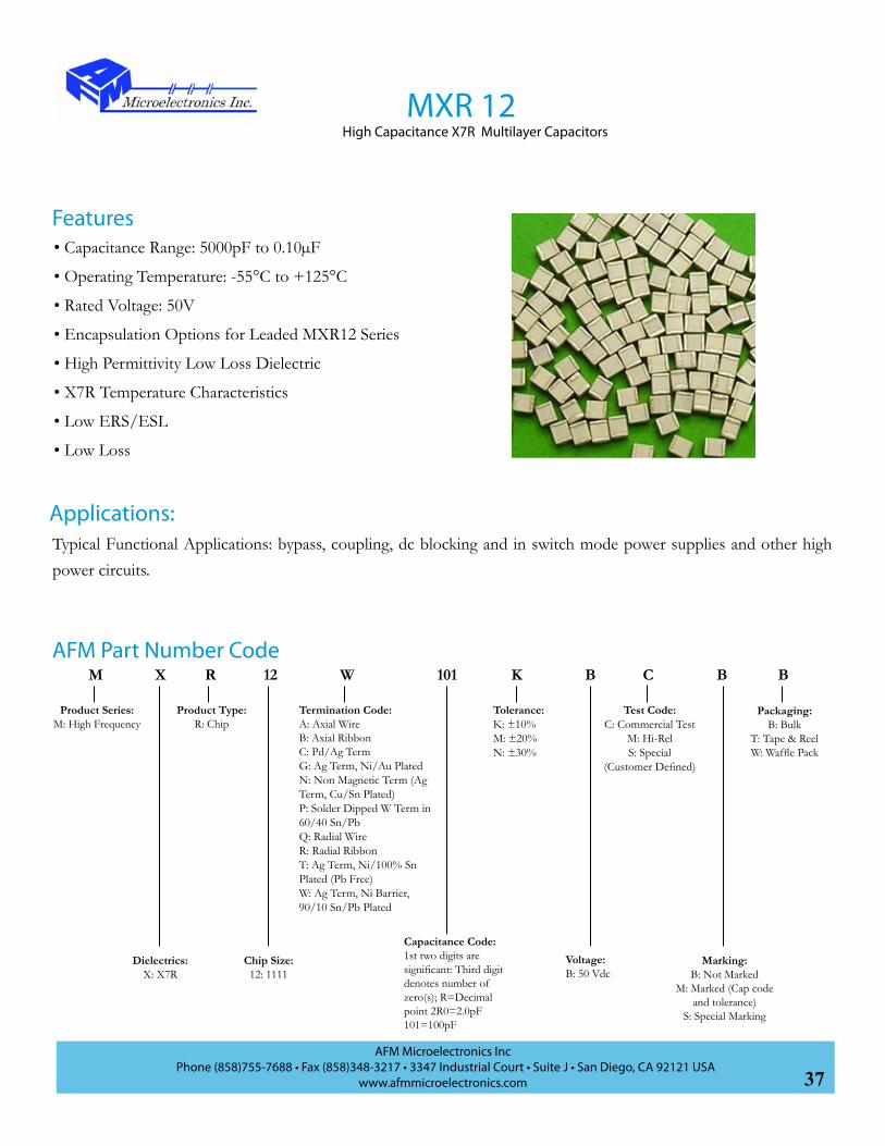
Typical Functional Applications: bypass, coupling, dc blocking and in switch mode power supplies and other high power circuits.
AFM Part Number Code
MXR 12High Capacitance X7R Multilayer Capacitors
Applications:
• Capacitance Range: 5000pF to 0.10µF
• Operating Temperature: -55°C to +125°C
• Rated Voltage: 50V
• Encapsulation Options for Leaded MXR12 Series
• High Permittivity Low Loss Dielectric
• X7R Temperature Characteristics
• Low ERS/ESL
• Low Loss
Features
M W12RX BK101 BB
Product Series:M: High Frequency
Dielectrics:X: X7R
Product Type:R: Chip
Chip Size:12: 1111
Termination Code:A: Axial WireB: Axial RibbonC: Pd/Ag TermG: Ag Term, Ni/Au PlatedN: Non Magnetic Term (Ag Term, Cu/Sn Plated)P: Solder Dipped W Term in 60/40 Sn/PbQ: Radial WireR: Radial RibbonT: Ag Term, Ni/100% Sn Plated (Pb Free)W: Ag Term, Ni Barrier, 90/10 Sn/Pb Plated
Capacitance Code:1st two digits are significant: Third digit denotes number of zero(s); R=Decimal point 2R0=2.0pF101=100pF
Tolerance:K: ±10%M: ±20%N: ±30%
Voltage:B: 50 Vdc
Marking:B: Not Marked
M: Marked (Cap code and tolerance)
S: Special Marking
Packaging:B: Bulk
T: Tape & ReelW: Waffle Pack
C
Test Code:C: Commercial Test
M: Hi-RelS: Special
(Customer Defined)

38AFM Microelectronics Inc
Phone (858)755-7688 • Fax (858)348-3217 • 3347 Industrial Court • Suite J • San Diego, CA 92121 USAwww.afmmicroelectronics.com
MXR 12High Capacitance X7R Multilayer Capacitors
Standard Capacitance ValuesChip Dimensions
Length .110in (2.79mm)
Width .110in (2.79mm)
Thickness .102in (2.59mm)
Band .015in (0.38mm)
W
B
L
T
Specification and PerformancePiezoelectric and Aging Effect: 3% Per Decade
Temperature Range: -55°C to +125°C
Temperature Coefficient of Capacitance: 0±15% Max
Dissipation Factor: 0.025 max at 1KHz and +25°C
Insulation Resistance (IR, at Rated Voltage):>104MΩ at +25°C>103MΩ at +125°C
Dielectric Withstand Voltage (DWV): 250% of rated WVDC for 5 secs
Capacitance Drift: ±0.02% or ±0.02pF, whichever is greater
Dielectric Absorption: ≤2%
Performance Curve
CAP Code
Cap Tol WVdc Cap Code
Cap Tol WVdc
502 5000pF
K, M, N
50
273 0.027µF
K, M, N
50
562 5600pF 333 0.033µF682 6800pF 393 0.039µF822 8200pF 473 0.047µF103 0.010µF 503 0.050µF123 0.012µF 563 0.056µF153 0.015µF 683 0.068µF183 0.018µF 823 0.082µF203 0.020µF 104 0.100µF
223 0.022µF
MXR 12 Series Resonance vs. Capacitance
10
100
1000
0.001 0.01 0.1
Capacitance (uF)
Fre
qu
ency
(M
Hz)
Resonance vs. Capacitance
Capacitance (pF)
Freq
uenc
y (M
Hz)
MXR 12 ESR vs. Capacitance
0.01
0.1
1
0.001 0.01 0.1
Capacitance (uF)
ES
R (
Oh
ms
)
ESR vs. Capacitance
Capacitance (pF)
ESR
(Ohm
s)

39AFM Microelectronics Inc
Phone (858)755-7688 • Fax (858)348-3217 • 3347 Industrial Court • Suite J • San Diego, CA 92121 USAwww.afmmicroelectronics.com
Termination OptionsCase Size 11 (0.055”x 0.057”)
SizeInternal
Electrode Orientation
A B C D
11Horizontal .125 (3.18) .075 (1.91) .025 (0.64) .05 (1.27)
Vertical .125 (3.18) .060 (1.52) .025 (0.64) .05 (1.27)
Recommended Pad Spacing Dimensions for the Size 11 Capacitors
B
A
D D
C
*NOTE: A= Max Length +0.030” B= Max Width +0.010” C= Min Length - 2 x Solder Band
All Dimensions are in Inches (mm)
AFM Series
TermCode Type Outlines
Body DimensionsInches (mm)
Lead and TerminationDimensions and Materials
Length(L) Width (W) Thickness
(T) (B) Materials
CASE SIZE 11
W Solder Plate
.057+.020-.010
inches(1.5
+0.51-0.25mm)
.055+.020-.010
inches(1.4
+0.51-0.25mm)
.055 (1.4 mm)
max
.015 (0.38)±.010 (0.25)
max
Solder Plated Over Nickel Barrier Termination90 Sn/10 Pb
P Pellet
.057+.035-.010
inches(1.5
+0.89-0.25mm)
.055+.035-.010
inches(1.4
+0.89-0.25mm)
W Termination with Sn/Pb Solder Dip
T Lead FreeSolder Plated
.057+.020-.010
inches(1.5
+0.51-0.25mm)
.055+.020-.010
inches(1.4
+0.51-0.25mm)
Lead-Free and RoHS Compliant
Tin Plated Over Nickel Barrier Termination
G Gold Plated
Lead-Free and RoHS Compliant
Gold Plated Over Nickel Barrier Termination
C Pd/Ag Palladium/Silver
Termination
NNon Magnetic
(Ag Term, Cu/Sn Plated)
Non-MagneticTermination
Silver TerminationCopper/Tin Plating
Termination OptionsCase Size 11 (0.055”x 0.057”)
W
B
L
T

40AFM Microelectronics Inc
Phone (858)755-7688 • Fax (858)348-3217 • 3347 Industrial Court • Suite J • San Diego, CA 92121 USAwww.afmmicroelectronics.com
Termination OptionsCase Size 12 (0.110”x0.110”)
AFM Series
TermCode Type Outlines
Body DimensionsInches (mm)
Lead and TerminationDimensions and Materials
Length(L) Width (W) Thickness
(T) B Materials
CASE SIZE 12
W Solder Plate
.110+.020-.010
inches(2.79
+0.51-0.25mm)
.110±.015inches
(2.79±0.38mm)
.102 (2.59)max
.015 (0.38)±.010 (0.25)max
Solder Plated Over Nickel Barrier Termination90 Sn/10 Pb
P Pellet
.110+.035-.010
inches(2.79
+0.89-0.25mm)
.110±.015inches
(2.79±0.38mm)
W Termination with Sn/Pb Solder Dip
T Lead FreeSolder Plated
.110+.020-.010
inches(2.79
+0.51-0.25mm)
.110±.015inches
(2.79±0.38mm)
Lead-Free and RoHS Compliant
Tin Plated Over Nickel Barrier Termination
G Gold Plated
Lead-Free and RoHS Compliant
Gold Plated Over Nickel BarrierTermination
C Pd/Ag Palladium/Silver
Termination
NNon Magnetic
(Ag Term, Cu/Sn Plated)
Non-MagneticTermination
Silver TerminationCopper/Tin Plating
SizeInternal
Electrode Orientation
A B C D
12Horizontal .170 (4.32) .140 (3.56) .070 (1.78) .050 (1.27)
Vertical .170 (4.32) .115 (2.92) .070 (1.78) .050 (1.27)
Recommended Pad Spacing Dimensions for Size 12 Capacitors
B
A
D D
C
*NOTE: A= Max. Length +0.030” B= Max. Width +0.010” C= Min. Length - 2 x Solder Band
All Dimensions are in Inches (mm)
Termination Options Case Size 12 (0.110”x0.110”)
W
B
L
T

41AFM Microelectronics Inc
Phone (858)755-7688 • Fax (858)348-3217 • 3347 Industrial Court • Suite J • San Diego, CA 92121 USAwww.afmmicroelectronics.com
Termination OptionsCase Size 03 (0.032”x0.063”)
SizeInternal
Electrode Orientation
A B C D
03Horizontal .110 (2.79) .040 (1.02) .024 (.610) .055 (1.40)
Vertical .110 (2.79) .040 (1.02) .024 (.610) .055 (1.40)
Recommended Pad Spacing Dimensions for Size 03 Capacitors
*NOTE: A= Max. Length +0.030”B= Max. Width +0.010”C= Min. Length - 2 x Solder Band
All Dimensions are in Inches (mm)
AFM Series
TermCode Type Outlines
Body DimensionsInches (mm)
Lead and TerminationDimensions and Materials
Length(L)
Width(W)
Thickness(T) (B) Materials
CASE SIZE 03
W Solder Plate
.063±.006inches(1.60
±0.15mm)
.032±.006inches
(0.81±0.15mm)
.035 inches (0.89mm)
max
.015 ±.01inches
(0.38±0.25mm)max
Solder Plated Over Nickel Barrier Termination90 Sn/10 Pb
P Pellet
.063±.015inches(1.60
±0.38mm)
W Termination with Sn/Pb Solder Dip
T Lead FreeSolder Plated
.063±.006inches(1.60
±0.15mm)
Lead-Free and RoHS Compliant
Tin Plated Over Nickel Barrier
Termination
G Gold Plated
.063±.006inches(1.60
±0.15mm)
Lead-Free and RoHS Compliant
Gold Plated Over Nickel BarrierTermination
C Pd/Ag
.063±.006inches(1.60
±0.15mm)
Palladium/Silver Termination
N
Non Magnetic (Ag Term,
Cu/Sn Plated)
.063±.006inches(1.60
±0.15mm)
Non-MagneticTermination
Silver TerminationCopper/Tin Plating
W
B
L
T
Termination OptionsCase Size 03 (0.032”x0.063”)
B
A
D D
C

42AFM Microelectronics Inc
Phone (858)755-7688 • Fax (858)348-3217 • 3347 Industrial Court • Suite J • San Diego, CA 92121 USAwww.afmmicroelectronics.com
Lead OptionsCase Size 12 (0.110”x0.110”)
Terminal Strength: (Excluding Non-Magnetic Types)
Leaded types shall withstand a lead pull of 22.25 Newton (5lbs) for 5 seconds, in the direction of the lead in accordance with
IEC 68-2-21 and MIL-STD-202 method 211.
Case Size
TermCode Style Outlines
Body DimensionsInches (mm)
Lead and TerminationDimensions and Materials
Length(L)
Width (W)
Thickness(T) Materials
12
M/MN Microstrip/
Non-Magnetic
.135±.015inches
(3.43±0.38)mm
.110±.015inches(2.79
±0.38)mm
.120 (3.05)max.
Length(LL )
Width(WL )
Thickness(TL )
.250 (6.35)min
.093±.005(2.36
±0.13)
.004±.001(.102
±.025)
B/BN Axial Ribbon/
Non-Magnetic
.102 (2.59)max.
R/RN Radial
Ribbon/Non-Magnetic
Q/QN
Radial Wire/Non-Magnetic .145
±.020inches
(3.68±0.51)mm
.500 (12.7) min
#26 AWG.,.016 (.406)dia nominal
A/AN Axial Wire/
Non-Magnetic
W
TL
L
T
L
LL
L
WL
LL
L
WL
LL
Lead Options Case Size 12 (0.110”x0.110”)

43AFM Microelectronics Inc
Phone (858)755-7688 • Fax (858)348-3217 • 3347 Industrial Court • Suite J • San Diego, CA 92121 USAwww.afmmicroelectronics.com
Kit No. Part No. Description Cap Range (pF) Cap Values (pF) Tolerance
(pF) Price $US
Kit 1 TEK001MPR11 Microporcelain Chip,
16 Values, 15 Pcs. Each Termination Option: “W”
0.1 to 2.00.1, 0.2, 0.3, 0.4, 0.5, 0.6, 0.7, 0.8,
0.9, 1.0, 1.1, 1.2, 1.5 ±0.1$120.00
1.6, 1.8, 2.0 ±0.25
Kit 2 TEK002MPR11 Microporcelain Chip,
16 Values, 15 Pcs. Each Termination Option: “W”
1.0 to 10
1.0, 1.2, 1.5, 1.8, 2.0, 2.2, 2.4, 2.7, 3.0, 3.3 ±0.1
$120.003.9, 4.7, 5.6, 6.8, 8.2 ±0.2510 ±5%
Kit 3 TEK003MPR11 Microporcelain Chip,
16 Values, 15 Pcs. Each Termination Option: “W”
10 to 100 10, 12, 15, 18, 20, 22, 24, 27, 30, 33, 39, 47, 56, 68, 82, 100 ±5% $120.00
Kit 4 TEK004MPR12 Microporcelain Chip,
16 Values, 15 Pcs. Each Termination Option: “W”
1.0 to 10
1.0, 1.2, 1.5, 1.8, 2.0, 2.2, 2.4, 2.7, 3.0, 3.3 ±0.1
$150.003.9, 4.7, 5.6, 6.8, 8.2 ±0.2510 ±5%
Kit 5 TEK005MPR12 Microporcelain Chip,
16 Values, 15 Pcs. Each Termination Option: “W”
10 to 100 10, 12, 15, 18, 20, 22, 24, 27, 30, 33, 39, 47, 56, 68, 82, 100 ±5% $150.00
Kit 6 TEK006MPR12 Microporcelain Chip,
16 Values, 15 Pcs. Each Termination Option: “W”
100 to 1000100, 120, 150, 180, 200, 220, 240,
270, 300, 330, 390, 470 ±5%$150.00
560, 680, 820, 1000 ±10%
Kit 7 TEK007
MNR03 C0G (NP0)Low ESR 0603 Capacitors
16 Values, 15 Pcs. Each Termination Option: “W”
0.1 to 2.0
0.1, 0.2, 0.3, 0.4, 0.5, 0.6, 0.7, 0.8, 0.9, 1.0, 1.1, 1.2, 1.5 ±0.1
$90.001.6, 1.8, 2.0 ±0.25
Kit 8 TEK008
MNR03 C0G (NP0)Low ESR 0603 Capacitors
16 Values, 15 Pcs. Each Termination Option: “W”
1.0 to 10
1.0, 1.2, 1.5, 1.8, 2.0, 2.2, 2.4, 2.7, 3.0, 3.3 ±0.1
$90.003.9, 4.7, 5.6, 6.8, 8.2 ±0.2510 ±5%
Kit 9 TEK009
MNR03 C0G (NP0)Low ESR 0603 Capacitors
16 Values, 15 Pcs. Each Termination Option: “W”
10 to 100 10, 12, 15, 18, 20, 22, 24, 27, 30, 33, 39, 47, 56, 68, 82, 100 ±5% $90.00
Engineering Kit Information
AFM offers design engineering kits for its RF/Microwave multilayer chip capacitor series. Each kit contains a range of the most
popular values of our Microporcelain and COG (NPO) dielectric systems. These engineering kits are offered in three different
sizes: MPR and MNR Series 11 (0.055” x 0.055”), MPR and MNR Series 12 (0.110” x 0.110”) and MNR Series 03 (0.063” x
0.032”). These engineering kits are to allow circuit designers to rapidly breadboard and optimize their circuits by having a variety
of capacitance values on hand.
These kits are normally in stock but may take several weeks ARO.

44AFM Microelectronics Inc
Phone (858)755-7688 • Fax (858)348-3217 • 3347 Industrial Court • Suite J • San Diego, CA 92121 USAwww.afmmicroelectronics.com
The MPH Series of capacitors are the updated version of Microelectronics Group MHP series and designed specifically for high voltage and high RF current applications. They are offered either in chip form, with axial or radial wire leads or axial silver ribbon leads. This configuration assures low ESR, minimum inductance and high RF current capabilities. Glass or epoxy encapsulation is available to protect the capacitors against contaminants and humidity and to minimize partial discharge activity. Non standard capacitance values, special tolerances and voltages, alternative dielectrics and other mechanical configurations are available. The MPH Series can be supplied compliant to the EU’s RoHS standard.
MPH Series OverviewHigh Power, High Current Capacitors
• MRI Coils
• HF/RF Power Amplifiers
• Plasma Chambers
• Antenna Tuning
• High Power RF Transmitters
• Inductive Heating
• Semiconductor Equipment
Applications• Capacitance Range: 1pF to 5100pF
• High Operating Voltages
- DC Voltage: 300Vdc to 7KVdc
- RF Voltage: 200Vrms to 5000Vrms
• RF Current Rating up to 12A rms
• Ultra Low ESR
• High Q
• Chip and Leaded Configurations Available
• Encapsulation Options Available
• High Reliability
Specification and Performance
Features
Piezoelectric and Aging Effects: None
Temperature Range: -55°C to +125°C
Temperature Coefficient of Capacitance (TCC): +90±30ppm/°C (-55°C to +125°C)
Q:>10,000 (1.0pF to 1000pF) at 1 MHz>10,000 (>1000pF) at 1KHz
Insulation Resistance:>105MΩ at 25°C , at 500VDC>104MΩ at 125°C , at 500VDC
Drift and Retrace: ±0.02% or 0.02pF Whichever is Greater

45AFM Microelectronics Inc
Phone (858)755-7688 • Fax (858)348-3217 • 3347 Industrial Court • Suite J • San Diego, CA 92121 USAwww.afmmicroelectronics.com
Series MPH
Range (Case Size Format) MPH25 MPH1 MPH2 MPH3
Ele
ctric
al C
hara
cter
istic
s
Capacitance Range (pF) 1-2700 1-5100 10-75 82-620Standard Capacitance Values E-24 E-24 E-24 E-24
Capacitance Tolerances B, C, D for capacitance C<10pF; F, G, J, K, M for capacitance C≥10pF; Capacitance Range (pF) for
Voltage Range1-
270300470
5101200
13001800
20002700
1-390 430680
7502200
24005100
10-75 82-155
160-330
360-620
VR Rated Voltage Vdc 2500 1500 1000 500 300 3600* 2500 1000 600 7000 7000 5000 3600
RF Rated Voltage Vrms 1768 1060 707 354 212 2500 1800 700 425 5000 5000 3500 2500
Test Voltage Vdc 3000 1800 1500 750 450 4320 3000 1500 900 8400 8400 6000 4320
Reactive Power (KVAR) Rating (kw)
4 2.2 1.5 1.2 1.0 12 6 6 3 18 18 18 12
RF Current Rating (Arms) 6 12
Dim
ensi
onal
Dat
a
Length of Chip (L) in (mm) .230 (5.84 ) (Non-Encapsulated) .380 (9.65) .760 (19.30)
Width of Chip (W) in (mm) .250 (6.35) (Non-Encapsulated) .380 (9.65) .760 (19.30)
Thickness of Chip (T) in (mm) (Encapsulated) (max) .145 (3.68) for Capacitance Value ≤680pF
.165 (4.19) for Capacitance Value ≥680pF.177 (4.50) may Increase to .236 (6.0) Max. After Glass Encapsulation
Ribbon Lead Dimensionin (mm)
Length: .500 (12.7) min Width: .24 (6.1) Thickness: .01 (0.25) Length: .750 (19.05) min Width: .350 (8.89) Thickness: .010 (0.25)
Con
stru
ctio
n Fe
atur
es
Rib
bon
Lead
ed
Lead Material Pure Silver (99.9%) Tin plated copper
Lead Bonding Silver Brazed 280°C Solder
Encapsulation Glass-Ceramic Coated on all 6 SidesHigh Frequency Polymer Optional
Glass-Ceramic Coated on 4 SidesHigh Frequency Polymer Optional
Wire
Lea
ded
MPH
25 O
nly
Lead Material Solder Coated Copper
Lead Bonding High Temperature Solder
Encapsulation Glass-Ceramic Coated on all 6 SidesHigh Frequency Polymer Optional
Lead Dimension Dia=0.024±0.002 (0.61±0.051) Lenth=0.5 (12.7) min
Condensed Data for MPH RF Power Capacitors
* 1-100pF with extended working voltage 7000Vdc
MPH Series OverviewHigh Power, High Current Capacitors

46AFM Microelectronics Inc
Phone (858)755-7688 • Fax (858)348-3217 • 3347 Industrial Court • Suite J • San Diego, CA 92121 USAwww.afmmicroelectronics.com
MPH 25(MHPO25)High Voltage High Current, High RF Power Capacitors
M W25HP HJ101 BB
Product Series:M: High Frequency
Dielectrics:P: Porcelain
Product Type:H: High Power
Chip Size:25: 2325
Capacitance Code:1st two digits are significant: Third digit denotes number of zero(s); R=Decimal point 2R0=2.0pF101=100pF
Tolerance:*B: ±0.1pFC: ±0.25pFD: ±0.5pFF: ±1%G: ±2%J: ±5%K: ±10%M: ±20%
*B,C,D for C<10pF
Voltage:H: 300 VdcJ: 500 VdcL: 1000 VdcN: 1500 VdcP: 2500 Vdc
Marking:B: Not MarkedM: Marked (Cap
code and tolerance)S: Special Marking
Packaging:B: BulkT: Tape & ReelW: Waffle Pack
AFM Part Number Code
C
Test Code:C: Commercial Test
S: Special (Customer Defined)
M: Hi-Rel
• MRI Coils
• HF/RF Power Amplifiers
• Plasma Chambers
• Antenna Tuning
• High Power RF Transmitters
• Inductive Heating
• Semiconductor Equipment
Applications
• Capacitance Range: 1pF to 2700pF
• High Q Low ESR/ESL
• High RF Power
• Ultra Stable Performance
• Operating Voltages
- DC Voltage: 300Vdc to 2500Vdc
- RF Voltage: 200Vrms to 1800Vrms
• RF Current Rating 6A rms
• Available with Encapsulation Option
Features
Termination Code:A: Axial Wire;AN: Non-Mag Axial WireB: Axial RibbonBN: Non-Mag Axial RibbonC: Pd/Ag TermG: Ag Term, Ni/Au PlatedM: MicrostripMN: Non-Mag MicrostripN: Non Magnetic Term(Ag Term., Cu/Sn Plated)P: Solder Dipped W Term in 60/40 Sn/PbQ: Radial WireQN: Non-Mag Radial WireT: Ag Term, Ni/100% Sn Plated (Pb Free)W: Ag Term, Ni Barrier, 90/10 Sn/Pb Plated

47AFM Microelectronics Inc
Phone (858)755-7688 • Fax (858)348-3217 • 3347 Industrial Court • Suite J • San Diego, CA 92121 USAwww.afmmicroelectronics.com
Specification and Performance
Standard Capacitance Values
Piezoelectric and Aging Effect: None
Temperature Range: -55°C to +125°C
Temperature Coefficient of Capacitance: +90±20ppm/°C
Quality Factor (Q) :>10,000 (1pF~1000pF) at 1MHz>10,000 (1100pF~2700pF) at 1KHz
Insulation Resistance (IR, at Rated Voltage):105MΩ min. at +25°C at rated WVDC104MΩ min. at +125°C at rated WVDC
Dielectric Withstand Voltage (DWV):1pF~470pF: 120% of rated WVDC for 5 secs;560pF~1200pF: 150% of rated WVDC for 5 secs;1500pF~2700pF: 250% of rated WVDC for 5 secs;
Capacitance Drift: ±0.02% or ±0.02pF, whichever is greater
MPH 25(MHPO25)High Voltage High Current, High RF Power Capacitors
Cap.Code
Cap.pF
Tol. WVDCV
Cap Code
Cap.pF
Tol. WVDCV
Cap Code
Cap.pF
Tol. WVDCV
1R0 1.0
B, C, D
2500
180 18
F, G, J, K, M 2500
331 330
F, G, J, K, M
15001R2 1.2 220 22 391 3901R5 1.5 270 27 471 4701R8 1.8 330 33 561 560
10002R2 2.2 390 39 681 6802R7 2.7 470 47 821 8203R3 3.3 560 56 102 10003R9 3.9 680 68 122 12004R7 4.7 820 82 152 1500 5005R6 5.6 101 100 182 18006R8 6.8 121 120 222 2200 3008R2 8.2 151 150 272 2700100 10 F, G, J, K,
M181 180
120 12 221 220150 15 271 270
* Special capacitance, tolances and WVDC are available, please consult with AFM.
48AFM Microelectronics Inc
Phone (858)755-7688 • Fax (858)348-3217 • 3347 Industrial Court • Suite J • San Diego, CA 92121 USAwww.afmmicroelectronics.com
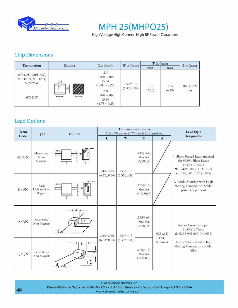
Chip Dimensions
Lead Options
Termination Outline Lin (mm) W in (mm) T in (mm) B in(mm)min max
MPH25C, MPH25G, MPH25N, MPH25T,
MPH25W
.230+.020~-.010
(5.84+0.51~- 0.25)) .250±.015
(6.35±0.38) .138(3.50)
.165(4.19)
.040 (1.02)max
MPH25P
230+.070~-.010
(5.84+1.78~-0.25)
MPH 25(MHPO25)High Voltage High Current, High RF Power Capacitors
Term Code Type Outline
Dimensions in (mm)Add .070 inches (1.77mm) if Encapsulated Lead Style
DesignationL W T d
M/MNMicrostrip/
Non-Magnetic
.245±.025(6.22±0.64)
.250±.015(6.35±0.38)
.145(3.68)Max for C≤680pF
1. Silver Braced leads attached for 99.9% Silver Leads
l: .500(12.7)minW: .240±.005 (6.10±0.127)t: .010±.001 (0.25±0.025)
2. Leads Attached with High Melting Temperature Solder
plated copper leadB/BNAxial
Ribbon/Non-Magneti
.165(4.19)Max for
C>680pF
A/AN Axial Wire/Non-Magneti
.245±.025(6.22±0.64)
.250±.015(6.35±0.38)
.145(3.68)Max for C≤680pF
.024 (.61) Dia.
Nominal
Solder Coated Copperl: .500(12.7)min
d: .024±.002 (0.610±0.051)
Leads Attached with High Melting Temperature Solder
AlloyQ/QN Radial Wire/
Non-Magneti
.165(4.19)Max for
C>680pF
W
T T
Lt
w
T
W
Lld
l
L
T
d

49AFM Microelectronics Inc
Phone (858)755-7688 • Fax (858)348-3217 • 3347 Industrial Court • Suite J • San Diego, CA 92121 USAwww.afmmicroelectronics.com
ESR vs.Capacitance ESR vs.Capacitance
Performance Curve
Environmental TestsMPH25 Series Capacitors are designed and manufactured to meet and exceed the requirements of EIA-198, MIL-PRF-55681 and MIL-PRF-123.
Item Specifications Method
Thermal ShockDWV: the initial valueIR: shall be not less than 30% the initial valueCapacitance Change: no more than 0.5% or 0.5pF
MIL-STD-202, Method 107, Condition A. At the maximum rated temperature (-55°C and +125°C) stay 30 minutes, the time of removing shall be not more than 3 minutes. Perform the five cycles.
Moisture Resistance
MIL-STD-202, Method 106
Humidity (steady state)
DWV: the initial valueIR: the initial valueCapacitance Change: no more than 0.3% or 0.3pF
MIL-STD-202, Method 103, Condition A, with 1.5 volts D.C. applied while subjected to an environment of 85°C with 85% relative humidity for 240 hours min.
LifeIR: shall be not less than 30% the initial valueCapacitance Change: no more than 0.2%
MiIL-Std-202, Method 108, for 2000 hours, at 125°C.no less than 1500V, 120% Rated voltage D.C. applied;less than 1500V, 150% rated voltage D.C. applied.
MPH 25(MHPO25)High Voltage High Current, High RF Power Capacitors

50AFM Microelectronics Inc
Phone (858)755-7688 • Fax (858)348-3217 • 3347 Industrial Court • Suite J • San Diego, CA 92121 USAwww.afmmicroelectronics.com
MPH 25(MHPO25)High Voltage High Current, High RF Power Capacitors
Q vs.Capacitance
Resonance vs.Capacitance Current Rating vs.Capacitance
Q vs.Capacitance

51AFM Microelectronics Inc
Phone (858)755-7688 • Fax (858)348-3217 • 3347 Industrial Court • Suite J • San Diego, CA 92121 USAwww.afmmicroelectronics.com
• Capacitance Range: 1pF to 5100pF
• High Q Low ESR/ESL
• High RF Power
• Ultra Stable Performance
• Operating Voltages
- DC Voltage: 600Vdc to 3600Vdc
- RF Voltage: 425Vrms to 2500Vrms
• Extended WVDC up to 7200 Vdc
• RF Current Rating 12A rms
• Available with Encapsulation Option
MPH 1 (MHP1-MHPU1)High Voltage High Current, High RF Power Capacitors
AFM Part Number Code
M
Product Series:M: High Frequency
H
Product Type:H: High Power
P
Dielectrics:P: Porcelain
1
Case Size:1: 3838
B J
Tolerance:F: ±1%G: ±2% J: ±5%K: ±10%M: ±20%
B
Packaging:B: Bulk
W: Waffle Pack
C
Test Code:C: Commercial Test
S: Special (Customer Defined)
M: Hi-Rel
101
Capacitance Code:1st two digits are significant: Third digit denotes number of zero(s); R=Decimal point 2R0=2.0pF101=100pF
R
Voltage:J: 500 VdcL: 1000 VdcP: 2500 VdcR: 3600 VdcT: 5000 Vdc U: 7200 Vdc
M
Marking:B: Not MarkedM: Marked (Cap code and tolerance)S: Special Marking
U
Blank: with encapsulated
U: Without encapsulated
G
Encapsulation:Blank: Without EncapsulatedG: Glass encapsulatedE: Epoxy encapsulatedU: Polymer Coating
• MRI Coils
• HF/RF Power Amplifiers
• Plasma Chambers
• Antenna Tuning
• High Power RF Transmitters
• Inductive Heating
• Semiconductor Equipment
ApplicationsFeatures
Termination Code:A: Axial Wire;AN: Non-Mag Axial WireB: Axial RibbonBN: Non-Mag Axial RibbonC: Pd/Ag TermG: Ag Term, Ni/Au PlatedM: MicrostripMN: Non-Mag MicrostripN: Non Magnetic Term(Ag Term., Cu/Sn Plated)P: Solder Dipped W Term in 60/40 Sn/PbQ: Radial WireQN: Non-Mag Radial WireT: Ag Term, Ni/100% Sn Plated (Pb Free)W: Ag Term, Ni Barrier, 90/10 Sn/Pb Plated

52AFM Microelectronics Inc
Phone (858)755-7688 • Fax (858)348-3217 • 3347 Industrial Court • Suite J • San Diego, CA 92121 USAwww.afmmicroelectronics.com
MPH 1 (MHP1-MHPU1)High Voltage, High Current, High RF Power Capacitors
* Special capacitance, tolances and WVDC are available, please consult with AFM.
Specification and Performance
Piezoelectric and Aging Effect: None
Temperature Range: -55°C to +125°C
Temperature Coefficient of Capacitance: +90±30ppm/°C
Quality Factor (Q) :>10,000 (1pF~1000pF) at 1MHz>10,000 (1100pF~5100pF) at 1KHz
Insulation Resistance (IR, at Rated Voltage):105MΩ min. at +25°C at rated WVDC104MΩ min. at +125°C at rated WVDC
Dielectric Withstand Voltage (DWV):1pF~680pF: 120% of rated WVDC for 5 secs;820pF~2200pF: 150% of rated WVDC for 5 secs;2700pF~5100pF: 250% of rated WVDC for 5 secs;
Capacitance Drift: ±0.02% or ±0.02pF, whichever is greater
Standard Capacitance Values *STD.:Standard Voltage; EXT.: Extended Voltage
CAPCODE
CAP (pF) TOL
RATED WVdc CAPCODE
CAP (pF) TOL
RATED WVdc CAPCODE
CAP (pF) TOL
RATED WVdc
STD.* EXT.* STD. EXT. STD. EXT.
1R0 1.0
B, C, D
3600 7200
220 22
F, G, J, K, M 3600
7200
471 470
F, G, J, K, M
3600
NA
1R2 1.2 270 27 561 560
1R5 1.5 330 33 681 6801R8 1.8 390 39 821 820
1000
2R2 2.2 470 47 102 10002R7 2.7 560 56 122 12003R3 3.3 680 68 152 15003R9 3.9 820 82 182 18004R7 4.7 101 100 222 22005R6 5.6 121 120
5000272 2700
G, J, K, M 500
6R8 6.8 151 150 332 33008R2 8.2 181 180 472 4700100 10
F, G, J, K, M
221 220
NA
512 5100120 12 271 270150 15 331 330
180 18 391 390

53AFM Microelectronics Inc
Phone (858)755-7688 • Fax (858)348-3217 • 3347 Industrial Court • Suite J • San Diego, CA 92121 USAwww.afmmicroelectronics.com
*STD.:Standard Voltage; EXT.: Extended Voltage
MPH 1 (MHP1-MHPU1)High Voltage, High Current, High RF Power Capacitors
Dim
ensi
onal
Dat
a
Length of Chip /Encapsulated (L) in (mm) .380 (9.65) /.550(13.97) max after encapsulation
Width of Chip/ Encapsulated (W) in (mm) .380 (9.65) / .550(13.97) max after encapsulation
Thickness of Chip (T) in (mm) (Encapsulated) (max)
.177 (4.50) may increase to
.236 (5.99) max. after glass encapsulation
All Dimensions are in Inches (mm)
.380 max(9.65)
.380 max(9.65)
.177 (4.50)
All Dimensions are in Inches (mm)Chip Dimensions
Lead Options
Term Code
Type OutlinesCapacitor Dimensions Lead Dimensions
Lead MaterialLength
(Lc)Width(Wc)
Thickness(Tc)
Length(Lc)
Width(Wc)
Thickness(Tc)
M/MN Microstrip/Non-Magnetic
.380+.015~-.010
(9.65+0.38~-0.25)
.038±.010
(9.65±0.25)
.177(4.5)max
.750(19.05)
min
.350±.010(8.89
±0.25)
.010±.005(0.25±0.13
Solder-platedCopper leaded
(Pure Silver Ribbon
with Glass Ecapsulation)
B/BN Axial Ribbon/Non-Magnetic
R Radial Ribbon .394 ±.039(10 ±1)
.114 ±.005(2.9 ±0.13)
.012 ±.002(0.3 ±0.05)
Q/QN Radial Wire/Non-Magnetic
.787(20)min
Dia.=.031 ±.004 (0.8 ±0.1)
A/ANAxial Wire/
Non-Magnetic1.18(30)min
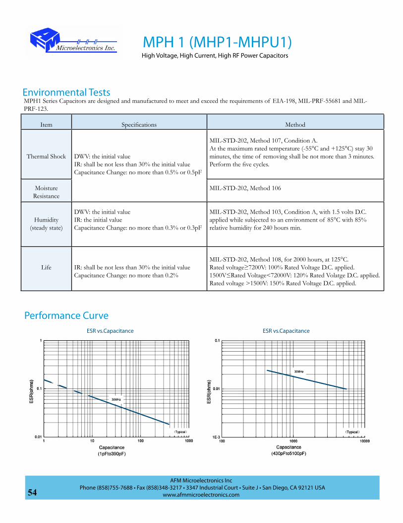
54AFM Microelectronics Inc
Phone (858)755-7688 • Fax (858)348-3217 • 3347 Industrial Court • Suite J • San Diego, CA 92121 USAwww.afmmicroelectronics.com
Environmental TestsMPH1 Series Capacitors are designed and manufactured to meet and exceed the requirements of EIA-198, MIL-PRF-55681 and MIL-PRF-123.
Item Specifications Method
Thermal Shock DWV: the initial valueIR: shall be not less than 30% the initial valueCapacitance Change: no more than 0.5% or 0.5pF
MIL-STD-202, Method 107, Condition A. At the maximum rated temperature (-55°C and +125°C) stay 30 minutes, the time of removing shall be not more than 3 minutes. Perform the five cycles.
Moisture Resistance
MIL-STD-202, Method 106
Humidity (steady state)
DWV: the initial valueIR: the initial valueCapacitance Change: no more than 0.3% or 0.3pF
MIL-STD-202, Method 103, Condition A, with 1.5 volts D.C. applied while subjected to an environment of 85°C with 85% relative humidity for 240 hours min.
Life IR: shall be not less than 30% the initial valueCapacitance Change: no more than 0.2%
MIL-STD-202, Method 108, for 2000 hours, at 125°C.Rated voltage≥7200V: 100% Rated Voltage D.C. applied.1500V≤Rated Voltage<72000V: 120% Rated Volatge D.C. applied.Rated voltage >1500V: 150% Rated Voltage D.C. applied.
MPH 1 (MHP1-MHPU1)High Voltage, High Current, High RF Power Capacitors
ESR vs.Capacitance ESR vs.Capacitance
Performance Curve

55AFM Microelectronics Inc
Phone (858)755-7688 • Fax (858)348-3217 • 3347 Industrial Court • Suite J • San Diego, CA 92121 USAwww.afmmicroelectronics.com
MPH 1 (MHP1-MHPU1)High Voltage, High Current, High RF Power Capacitors
Q vs.Capacitance Q vs.Capacitance
Resonance vs.Capacitance Current Rating vs.Capacitance

56AFM Microelectronics Inc
Phone (858)755-7688 • Fax (858)348-3217 • 3347 Industrial Court • Suite J • San Diego, CA 92121 USAwww.afmmicroelectronics.com
• Capacitance Range: 10pF to 75pF
• High Q Low ESR/ESL
• High RF Power
• Ultra Stable Performance • Operating Voltages - DC Voltage: 7000Vdc - RF Voltage: 5000Vrms• RF Current Rating: 12A rms
• Available with Encapsulation Option
MPH 2 (MHP2-MHPU2)High Power, High Current, Silver Ribbon Leaded Capacitors
Features• MRI Coils
• HF/RF Power Amplifiers
• Plasma Chambers
• Antenna Tuning
• High Power RF Transmitters
• Inductive Heating
• Semiconductor Equipment
Applications
AFM Part Number CodeM
Product Series:M: High Frequency
H
Product Type:H: High Power
P
Dielectrics:P: Porcelain
2
Case Size:2: 7638
B
Termination Code:B: Axial RibbonC: Pd/Ag TermN: Non Magnetic Term (Ag Term, Cu/Sn Plated)P: Solder Dipped W Term in 60/40 Sn/PbT: Ag Term, Ni/100% Sn Plated (Pb Free)U: UnencapsulatedW: Ag Term, Ni Barrier, 90/10 Sn/Pb Plated
J
Tolerance:F: ±1%G: ±2% J: ±5% K: ±10% M: ±20%
B
Packaging:B: Bulk
W: Waffle Pack
C
Test Code:C: Commercial Test
S: Special (Customer Defined)
M: Hi-Rel
101
Capacitance Code:1st two digits are significant: Third digit denotes number of zero(s); R=Decimal point 2R0=2.0pF101=100pF
K
Voltage:U: 7000 Vdc
M
Marking:B: Not MarkedM: Marked (Cap code and tolerance)S: Special Marking
U
Blank: with encapsulated
U: Without encapsulated
G
Encapsulation:Blank: Without EncapsulatedG: Glass encapsulatedE: Epoxy encapsulatedU: Other ploymer encapsulated
Specification and PerformancePiezoelectric and Aging Effect: None
Temperature Range: -55°C to +125°C
Temperature Coefficient of Capacitance: +90±30ppm/°C
Quality Factor (Q) : >10,000 (1pF~1000pF) at 1MHz; >10,000 (1100pF~5100pF) at 1KHz
Insulation Resistance (IR, Test Voltage 500V): 105MΩ min. at +25°C at rated WVDC; 104MΩ min. at +125°C at rated WVDC
Capacitance Drift: ±0.02% or ±0.02pF, whichever is greater

57AFM Microelectronics Inc
Phone (858)755-7688 • Fax (858)348-3217 • 3347 Industrial Court • Suite J • San Diego, CA 92121 USAwww.afmmicroelectronics.com
Con
stru
ctio
n Fe
atur
es
Rib
bon
Lead
ed
Lead Material Pure Silver (99.9%)
Solder Plated Copper
Lead Bonding Silver Brazed 280oC Solder
Encapsulation
Glass-Ceramic
Coated on all 6 Sides
Glass-Ceramic
Coated on all 4 Sides
Dim
ensi
onal
Dat
a
Length of Chip / Encapsulated (L) in (mm) .760 (19.3)/ 1.062 (26.97) max after encapsulation
Width of Chip/ Encapsulated (W) in (mm) .380 (9.65)/.550 (13.97) max after encapsulation
Thickness of Chip (T) in (mm) (Encapsulated) (max)
.177 (4.50) may increase to .236 (5.99) max. after glass encapsulation
Ribbon Lead (Axial) in (mm)Length: .750 (19.05) Width: .350 (8.89)
Thickness: .010 (0.25)
1.062 max(26.97)
.750 min(19.05)
.35(8.89)
.236 max(5.99)
.010 max(0.25)
.550 max
(13.97)
.760 max(19.3)
.380 max(9.65)
.177 (4.50)
Standard Capacitance Values
All Dimensions are in Inches (mm)Chip Dimensions
All Dimensions are in Inches (mm)Lead Options
MPH 2 (MHP2-MHPU2)High Power, High Current, Silver Ribbon Leaded Capacitors
CAPCODE
CAP (pF) TOL WVDCV
CAPCODE
CAP (pF) TOL WVDCV
100 10
F, G, J, K, M 7000
330 33
F, G, J, K, M 7000
110 11 360 36
120 12 390 39
130 13 430 43
150 15 470 47
160 16 510 51
180 18 560 56
200 20 620 62
220 22 680 68
240 24 750 75
270 27
300 30

58AFM Microelectronics Inc
Phone (858)755-7688 • Fax (858)348-3217 • 3347 Industrial Court • Suite J • San Diego, CA 92121 USAwww.afmmicroelectronics.com
AFM Part Number CodeM
Product Series:M: High Frequency
H
Product Type:H: High Power
P
Dielectrics:P: Porcelain
3
Case Size:3: 7676
B
Termination Code:B: Axial RibbonC: Pd/Ag TermN: Non Magnetic Term (Ag Term, Cu/Sn Plated)P: Solder Dipped W Term in 60/40 Sn/PbT: Ag Term, Ni/100% Sn Plated (Pb Free)U: UnencapsulatedW: Ag Term, Ni Barrier, 90/10 Sn/Pb Plated
J
Tolerance:F: ±1%G: ±2%J: ±5%K: ±10%M: ±20%
B
Packaging:B: Bulk
W: Waffle Pack
C
Test Code:C: Commercial Test
S: Special (Customer Defined)
M: Hi-Rel
101
Capacitance Code:1st two digits are significant: Third digit denotes number of zero(s); R=Decimal point 2R0=2.0pF101=100pF
K
Voltage:R: 3600 VdcT: 5000 Vdc U: 7000 Vdc
M
Marking:B: Not MarkedM: Marked (Cap code and tolerance)S: Special Marking
U
Blank: with encapsulated
U: Without encapsulated
G
Encapsulation:Blank: Without EncapsulatedG: Glass encapsulatedE: Epoxy encapsulatedU: Other ploymer encapsulated
MPH 3 (MHP3-MHPU3)High Power, High Current, Silver Ribbon Leaded Capacitors
• MRI Coils
• HF/RF Power Amplifiers
• Plasma Chambers
• Antenna Tuning
• High Power RF Transmitters
• Inductive Heating
• Semiconductor Equipment
Applications
Specification and Performance:Piezoelectric and Aging Effect: None Exhibited
Temperature Range: -55°C to +125°C
Temperature Coefficient of Capacitance: +90±30ppm/°C
Quality Factor (Q) : >10,000 (1pF~1000pF) at 1MHz; >10,000 (1100pF~5100pF) at 1KHz
Insulation Resistance (IR, at Rated Voltage): 105MΩ min. at +25°C at rated WVDC; 104MΩ min. at +125°C at rated WVDC
Capacitance Drift: ±0.02% or ±0.02pF, whichever is greater
• Capacitance Range: 82pF to 620pF
• High Q Low ESR/ESL
• High RF Power
• Ultra Stable Performance
• Operating Voltages
- DC Voltage: 3600Vdc to 7000Vdc
- RF Voltage: 2500Vrms to 5000Vrms
• RF Current Rating 12A rms
• Available with Encapsulation Option, Chip
and Leaded Configurations
Features

59AFM Microelectronics Inc
Phone (858)755-7688 • Fax (858)348-3217 • 3347 Industrial Court • Suite J • San Diego, CA 92121 USAwww.afmmicroelectronics.com
Con
stru
ctio
n Fe
atur
es
Rib
bon
Lead
ed
Lead Material Pure Silver (99.9%)
Lead Bonding Silver Brazed
EncapsulationGlass-Ceramic Coated on all
6 SidesEpoxy Encapsulation Optional
1.062 max(26.97)
.750 min(19.05)
.35(8.89)
.236 max(5.99)
.010 max(0.25)
1.062 max
(26.97)
.760 max(19.3)
.760 max(19.3)
.177 (4.50)
Standard Capacitance Values
Dim
ensi
onal
Dat
a
Length of Chip/ Encapsulated (L) in (mm)
.760 (19.3)/ 1.062 (26.97) max after encapsulation
Width of Chip /Encapsulated (W) in (mm)
.760 (19.3)/ 1.062 (26.97) max after encapsulation
Thickness of Chip (T) in (mm) (Encapsulated) (max)
.177 (4.50) May Increase to .236 (5.99) Max. After Glass
Encapsulation
Ribbon Lead (Axial) in (mm)
Length: .750 (19.05)Width: .350 (8.89)
Thickness: .010 (0.25)
All Dimensions are in Inches (mm)Chip Dimensions
All Dimensions are in Inches (mm)Lead Options
MPH 3 (MHP3-MHPU3)High Power, High Current, Silver Ribbon Leaded Capacitors
CAPCODE
CAP (pF) TOL WVDCV
CAPCODE
CAP (pF) TOL WVDCV
820 82
F, G, J, K, M
7000
271 270
F, G, J, K, M
5000910 91 301 300101 100 331 330111 110 361 360
3600
121 120 391 390131 130 431 430151 150 471 470
161 160
5000
511 510181 180 561 560201 200 621 620221 220241 240

60AFM Microelectronics Inc
Phone (858)755-7688 • Fax (858)348-3217 • 3347 Industrial Court • Suite J • San Diego, CA 92121 USAwww.afmmicroelectronics.com
MNH 25High Voltage, High Current, High RF Power Capacitors
M W25HN HJ101 BB
Product Series:M: High Frequency
Dielectrics:N: NPO
Product Type:H: High Power
Chip Size:25: 2325
Termination Code:A: Axial Wire;AN: Non-Mag Axial WireB: Axial RibbonBN: Non-Mag Axial RibbonC: Pd/Ag TermG: Ag Term, Ni/Au PlatedM: MicrostripMN: Non-Mag MicrostripN: Non Magnetic Term(Ag Term., Cu/Sn Plated)P: Solder Dipped W Term in 60/40 Sn/PbQ: Radial WireQN: Non-Mag Radial WireT: Ag Term, Ni/100% Sn Plated (Pb Free)W: Ag Term, Ni Barrier, 90/10 Sn/Pb Plated
Capacitance Code:1st two digits are significant: Third digit denotes number of zero(s); R=Decimal point 2R0=2.0pF101=100pF
Tolerance:*B: ±0.1pFC: ±0.25pFD: ±0.5pFF: ±1%G: ±2%J: ±5%K: ±10%M: ±20%
*B,C,D for C<10pF
Voltage:H: 300 VdcJ: 500 VdcL: 1000 VdcN: 1500 VdcP: 2500 Vdc
Marking:B: Not MarkedM: Marked (Cap
code and tolerance)S: Special Marking
Packaging:B: BulkT: Tape & ReelW: Waffle Pack
AFM Part Number Code
C
Test Code:C: Commercial Test
S: Special (Customer Defined)
M: Hi-Rel
• MRI Coils
• HF/RF Power Amplifiers
• Plasma Chambers
• Antenna Tuning
• High Power RF Transmitters
• Inductive Heating
• Semiconductor Equipment
Applications
• Capacitance Range: 1pF to 2700pF
• High Q Low ESR/ESL
• High RF Power
• Ultra Stable Performance
• Operating Voltages
- DC Voltage: 300Vdc to 2500Vdc
- RF Voltage: 200Vrms to 1800Vrms
• RF Current Rating 6A rms
• Available with Encapsulation Option
Features

61AFM Microelectronics Inc
Phone (858)755-7688 • Fax (858)348-3217 • 3347 Industrial Court • Suite J • San Diego, CA 92121 USAwww.afmmicroelectronics.com
Specification and Performance
Standard Capacitance Values
Piezoelectric and Aging Effect: None
Temperature Range: -55°C to +125°C
Temperature Coefficient of Capacitance: 0±30ppm/°C
Quality Factor (Q) :>10,000 (1pF~1000pF) at 1MHz>10,000 (1100pF~2700pF) at 1KHz
Insulation Resistance (IR, at Rated Voltage):
1pF~2700pF:105MΩ min. at +25°C at rated WVDC104MΩ min. at +125°C at rated WVDCMax. test voltage is 500VDC.
Dielectric Withstand Voltage (DWV):1pF~470pF: 120% of rated WVDC for 5 secs;560pF~1200pF: 150% of rated WVDC for 5 secs;1500pF~2700pF: 250% of rated WVDC for 5 secs;
Capacitance Drift: ±0.02% or ±0.02pF, whichever is greater
MNH 25High Voltage, High Current, High RF Power Capacitors
Cap.Code
Cap.pF
Tol. WVDCV
Cap Code
Cap.pF
Tol. WVDCV
Cap Code
Cap.pF
Tol. WVDCV
1R0 1.0
C, D
2500
180 18
G, J, K, M 2500
331 330
G, J, K, M
15001R2 1.2 220 22 391 3901R5 1.5 270 27 471 4701R8 1.8 330 33 561 560
10002R2 2.2 390 39 681 6802R7 2.7 470 47 821 8203R3 3.3 560 56 102 10003R9 3.9 680 68 122 12004R7 4.7 820 82 152 1500 5005R6 5.6 101 100 182 18006R8 6.8 121 120 222 2200 3008R2 8.2 151 150 272 2700100 10
G, J, K, M
181 180120 12 221 220
150 15 271 270
* Special capacitance, tolances and WVDC are available, please consult with AFM.

62AFM Microelectronics Inc
Phone (858)755-7688 • Fax (858)348-3217 • 3347 Industrial Court • Suite J • San Diego, CA 92121 USAwww.afmmicroelectronics.com
Term Code Type Outline
Dimensions in (mm)Add .070 inches (1.77mm) if Encapsulated Lead Style
DesignationL W T d
M/MNMicrostrip/
Non-Magnetic
.245±.025(6.22±0.64)
.250±.015(6.35±0.38)
.145(3.68)Max for C≤680pF
1. Silver Braced leads attached for 99.9% Silver Leads
l: .500(12.7)minW: .240±.005 (6.10±0.127)t: .010±.001 (0.25±0.025)
2. Leads Attached with High Melting Temperature Solder
plated copper leadB/BNAxial
Ribbon/Non-Magneti
.165(4.19)Max for
C>680pF
A/AN Axial Wire/Non-Magneti
.245±.025(6.22±0.64)
.250±.015(6.35±0.38)
.145(3.68)Max for C≤680pF
.024 (.61) Dia.
Nominal
Solder Coated Copperl: .500(12.7)min
d: .024±.002 (0.610±0.051)
Leads Attached with High Melting Temperature Solder
AlloyQ/QN Radial Wire/
Non-Magneti
.165(4.19)Max for
C>680pF
Chip Dimensions
Lead Options
Termination Outline Lin (mm) W in (mm) T in (mm) B in(mm)min max
MNH25C, MNH25G, MNH25N, MNH25T,
MNH25W
.230+.020~-.010
(5.84+0.51~- 0.25)) .250±.015
(6.35±0.38) .138(3.50)
.165(4.19)
.040 (1.02)max
MNH25P
230+.070~-.010
(5.84+1.78~-0.25)
W
T T
Lt
w
T
W
Lld
l
L
T
d
MNH 25High Voltage, High Current, High RF Power Capacitors

63AFM Microelectronics Inc
Phone (858)755-7688 • Fax (858)348-3217 • 3347 Industrial Court • Suite J • San Diego, CA 92121 USAwww.afmmicroelectronics.com
ESR vs.Capacitance ESR vs.Capacitance
Performance Curve
Environmental TestsMNH25 Series Capacitors are designed and manufactured to meet and exceed the requirements of EIA-198, MIL-PRF-55681 and MIL-PRF-123.
Item Specifications Method
Thermal ShockDWV: the initial valueIR: shall be not less than 30% the initial valueCapacitance Change: no more than 0.5% or 0.5pF
MIL-STD-202, Method 107, Condition A. At the maximum rated temperature (-55°C and +125°C) stay 30 minutes, the time of removing shall be not more than 3 minutes. Perform the five cycles.
Moisture Resistance
MIL-STD-202, Method 106
Humidity (steady state)
DWV: the initial valueIR: the initial valueCapacitance Change: no more than 0.3% or 0.3pF
MIL-STD-202, Method 103, Condition A, with 1.5 volts D.C. applied while subjected to an environment of 85°C with 85% relative humidity for 240 hours min.
LifeIR: shall be not less than 30% the initial valueCapacitance Change: no more than 0.2%
MiIL-Std-202, Method 108, for 2000 hours, at 125°C.no less than 1500V, 120% Rated voltage D.C. applied;less than 1500V, 150% rated voltage D.C. applied.
MNH 25High Voltage, High Current, High RF Power Capacitors

64AFM Microelectronics Inc
Phone (858)755-7688 • Fax (858)348-3217 • 3347 Industrial Court • Suite J • San Diego, CA 92121 USAwww.afmmicroelectronics.com
MNH 25High Voltage, High Current, High RF Power Capacitors
Q vs.Capacitance
Resonance vs.Capacitance Current Rating vs.Capacitance
Q vs.Capacitance
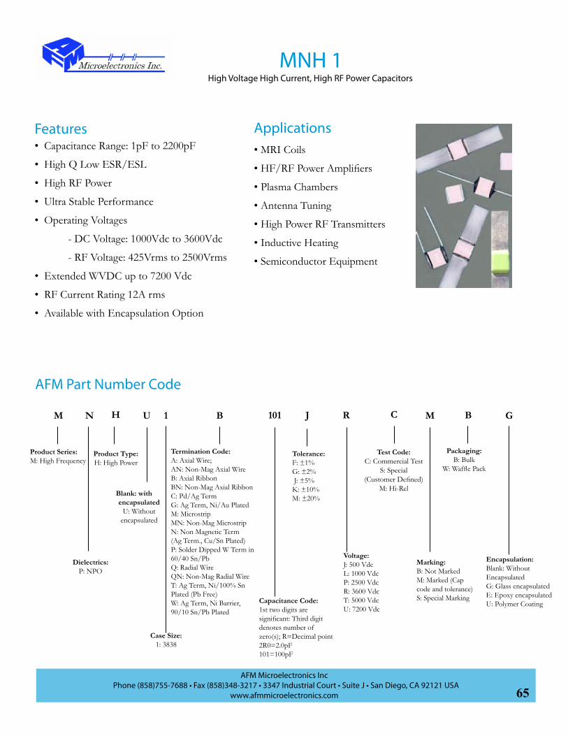
65AFM Microelectronics Inc
Phone (858)755-7688 • Fax (858)348-3217 • 3347 Industrial Court • Suite J • San Diego, CA 92121 USAwww.afmmicroelectronics.com
• Capacitance Range: 1pF to 2200pF
• High Q Low ESR/ESL
• High RF Power
• Ultra Stable Performance
• Operating Voltages
- DC Voltage: 1000Vdc to 3600Vdc
- RF Voltage: 425Vrms to 2500Vrms
• Extended WVDC up to 7200 Vdc
• RF Current Rating 12A rms
• Available with Encapsulation Option
MNH 1High Voltage High Current, High RF Power Capacitors
AFM Part Number Code
M
Product Series:M: High Frequency
H
Product Type:H: High Power
N
Dielectrics:P: NPO
1
Case Size:1: 3838
B J
Tolerance:F: ±1%G: ±2% J: ±5%K: ±10%M: ±20%
B
Packaging:B: Bulk
W: Waffle Pack
C
Test Code:C: Commercial Test
S: Special (Customer Defined)
M: Hi-Rel
101
Capacitance Code:1st two digits are significant: Third digit denotes number of zero(s); R=Decimal point 2R0=2.0pF101=100pF
R
Voltage:J: 500 VdcL: 1000 VdcP: 2500 VdcR: 3600 VdcT: 5000 Vdc U: 7200 Vdc
M
Marking:B: Not MarkedM: Marked (Cap code and tolerance)S: Special Marking
U
Blank: with encapsulated
U: Without encapsulated
G
Encapsulation:Blank: Without EncapsulatedG: Glass encapsulatedE: Epoxy encapsulatedU: Polymer Coating
• MRI Coils
• HF/RF Power Amplifiers
• Plasma Chambers
• Antenna Tuning
• High Power RF Transmitters
• Inductive Heating
• Semiconductor Equipment
ApplicationsFeatures
Termination Code:A: Axial Wire;AN: Non-Mag Axial WireB: Axial RibbonBN: Non-Mag Axial RibbonC: Pd/Ag TermG: Ag Term, Ni/Au PlatedM: MicrostripMN: Non-Mag MicrostripN: Non Magnetic Term(Ag Term., Cu/Sn Plated)P: Solder Dipped W Term in 60/40 Sn/PbQ: Radial WireQN: Non-Mag Radial WireT: Ag Term, Ni/100% Sn Plated (Pb Free)W: Ag Term, Ni Barrier, 90/10 Sn/Pb Plated

66AFM Microelectronics Inc
Phone (858)755-7688 • Fax (858)348-3217 • 3347 Industrial Court • Suite J • San Diego, CA 92121 USAwww.afmmicroelectronics.com
MNH 1High Voltage, High Current, High RF Power Capacitors
* Special capacitance, tolances and WVDC are available, please consult with AFM.
Specification and Performance
Piezoelectric and Aging Effect: None
Temperature Range: -55°C to +125°C
Temperature Coefficient of Capacitance: 0±30ppm/°C
Quality Factor (Q) :>10,000 (1pF~1000pF) at 1MHz>10,000 (1100pF~5100pF) at 1KHz
Insulation Resistance (IR, at Rated Voltage):105MΩ min. at +25°C at rated WVDC104MΩ min. at +125°C at rated WVDC
Dielectric Withstand Voltage (DWV):1pF~680pF: 120% of rated WVDC for 5 secs;820pF~2200pF: 150% of rated WVDC for 5 secs;2700pF~5100pF: 250% of rated WVDC for 5 secs;
Capacitance Drift: ±0.02% or ±0.02pF, whichever is greater
CAPCODE
CAP (pF) TOL
RATED WVdc CAPCODE
CAP (pF) TOL
RATED WVdc CAPCODE
CAP (pF) TOL
RATED WVdc
STD.* EXT.* STD. EXT. STD. EXT.
1R0 1.0
B, C, D
3600 7200
220 22
F, G, J, K, M 3600
7200
471 470
F, G, J, K, M
3600
NA
1R2 1.2 270 27 561 560
1R5 1.5 330 33 681 6801R8 1.8 390 39 821 820
1000
2R2 2.2 470 47 102 10002R7 2.7 560 56 122 12003R3 3.3 680 68 152 15003R9 3.9 820 82 182 18004R7 4.7 101 100 222 22005R6 5.6 121 120
5000272 2700
G, J, K, M 500
6R8 6.8 151 150 332 33008R2 8.2 181 180 472 4700100 10
F, G, J, K, M
221 220
NA
512 5100120 12 271 270150 15 331 330
180 18 391 390
Standard Capacitance Values *STD.:Standard Voltage; EXT.: Extended Voltage
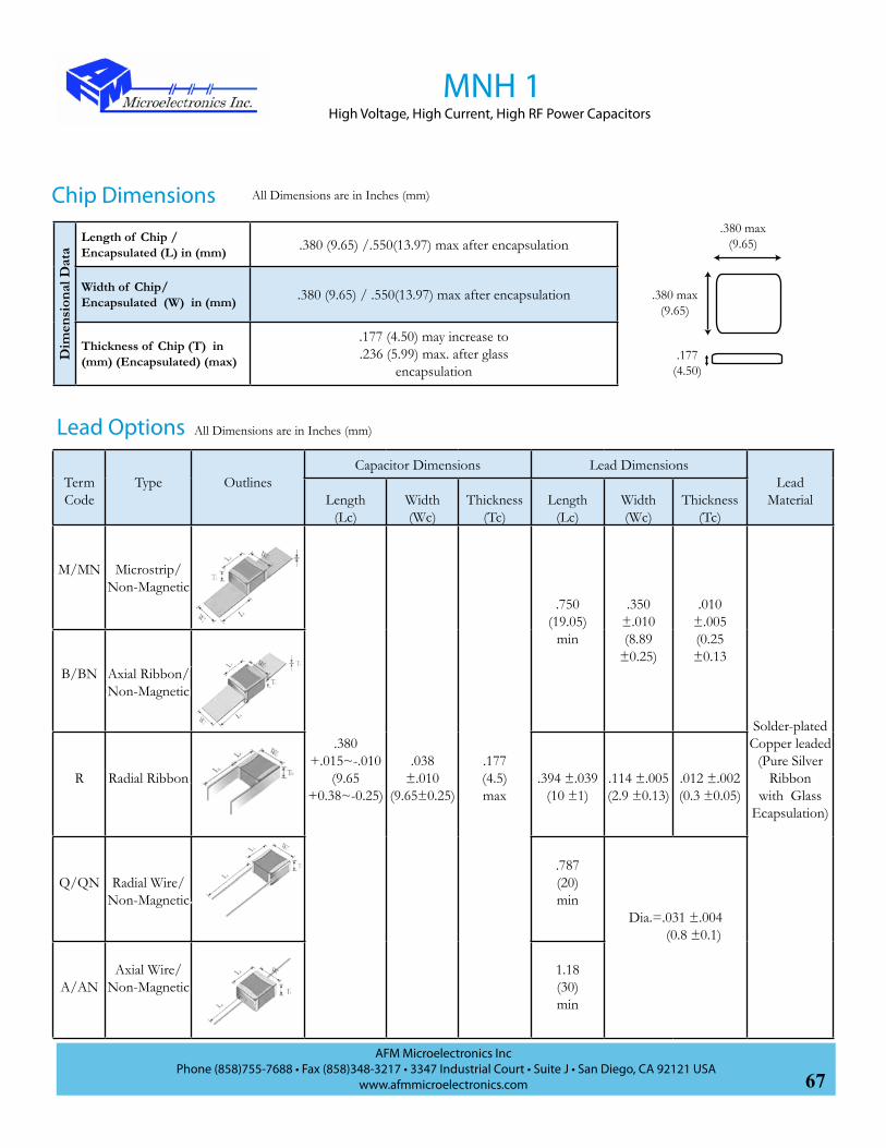
67AFM Microelectronics Inc
Phone (858)755-7688 • Fax (858)348-3217 • 3347 Industrial Court • Suite J • San Diego, CA 92121 USAwww.afmmicroelectronics.com
*STD.:Standard Voltage; EXT.: Extended Voltage
MNH 1High Voltage, High Current, High RF Power Capacitors
Term Code
Type OutlinesCapacitor Dimensions Lead Dimensions
Lead MaterialLength
(Lc)Width(Wc)
Thickness(Tc)
Length(Lc)
Width(Wc)
Thickness(Tc)
M/MN Microstrip/Non-Magnetic
.380+.015~-.010
(9.65+0.38~-0.25)
.038±.010
(9.65±0.25)
.177(4.5)max
.750(19.05)
min
.350±.010(8.89
±0.25)
.010±.005(0.25±0.13
Solder-platedCopper leaded
(Pure Silver Ribbon
with Glass Ecapsulation)
B/BN Axial Ribbon/Non-Magnetic
R Radial Ribbon .394 ±.039(10 ±1)
.114 ±.005(2.9 ±0.13)
.012 ±.002(0.3 ±0.05)
Q/QN Radial Wire/Non-Magnetic
.787(20)min
Dia.=.031 ±.004 (0.8 ±0.1)
A/ANAxial Wire/
Non-Magnetic1.18(30)min
Dim
ensi
onal
Dat
a
Length of Chip /Encapsulated (L) in (mm) .380 (9.65) /.550(13.97) max after encapsulation
Width of Chip/ Encapsulated (W) in (mm) .380 (9.65) / .550(13.97) max after encapsulation
Thickness of Chip (T) in (mm) (Encapsulated) (max)
.177 (4.50) may increase to
.236 (5.99) max. after glass encapsulation
All Dimensions are in Inches (mm)
.380 max(9.65)
.380 max(9.65)
.177 (4.50)
All Dimensions are in Inches (mm)Chip Dimensions
Lead Options

68AFM Microelectronics Inc
Phone (858)755-7688 • Fax (858)348-3217 • 3347 Industrial Court • Suite J • San Diego, CA 92121 USAwww.afmmicroelectronics.com
Environmental TestsMNH1 Series Capacitors are designed and manufactured to meet and exceed the requirements of EIA-198, MIL-PRF-55681 and MIL-PRF-123.
Item Specifications Method
Thermal Shock DWV: the initial valueIR: shall be not less than 30% the initial valueCapacitance Change: no more than 0.5% or 0.5pF
MIL-STD-202, Method 107, Condition A. At the maximum rated temperature (-55°C and +125°C) stay 30 minutes, the time of removing shall be not more than 3 minutes. Perform the five cycles.
Moisture Resistance
MIL-STD-202, Method 106
Humidity (steady state)
DWV: the initial valueIR: the initial valueCapacitance Change: no more than 0.3% or 0.3pF
MIL-STD-202, Method 103, Condition A, with 1.5 volts D.C. applied while subjected to an environment of 85°C with 85% relative humidity for 240 hours min.
Life IR: shall be not less than 30% the initial valueCapacitance Change: no more than 0.2%
MIL-STD-202, Method 108, for 2000 hours, at 125°C.Rated voltage≥7200V: 100% Rated Voltage D.C. applied.1500V≤Rated Voltage<72000V: 120% Rated Volatge D.C. applied.Rated voltage >1500V: 150% Rated Voltage D.C. applied.
MNH 1High Voltage, High Current, High RF Power Capacitors
ESR vs.Capacitance ESR vs.Capacitance
Performance Curve

69AFM Microelectronics Inc
Phone (858)755-7688 • Fax (858)348-3217 • 3347 Industrial Court • Suite J • San Diego, CA 92121 USAwww.afmmicroelectronics.com
MNH 1 High Voltage, High Current, High RF Power Capacitors
Q vs.Capacitance Q vs.Capacitance
Resonance vs.Capacitance Current Rating vs.Capacitance
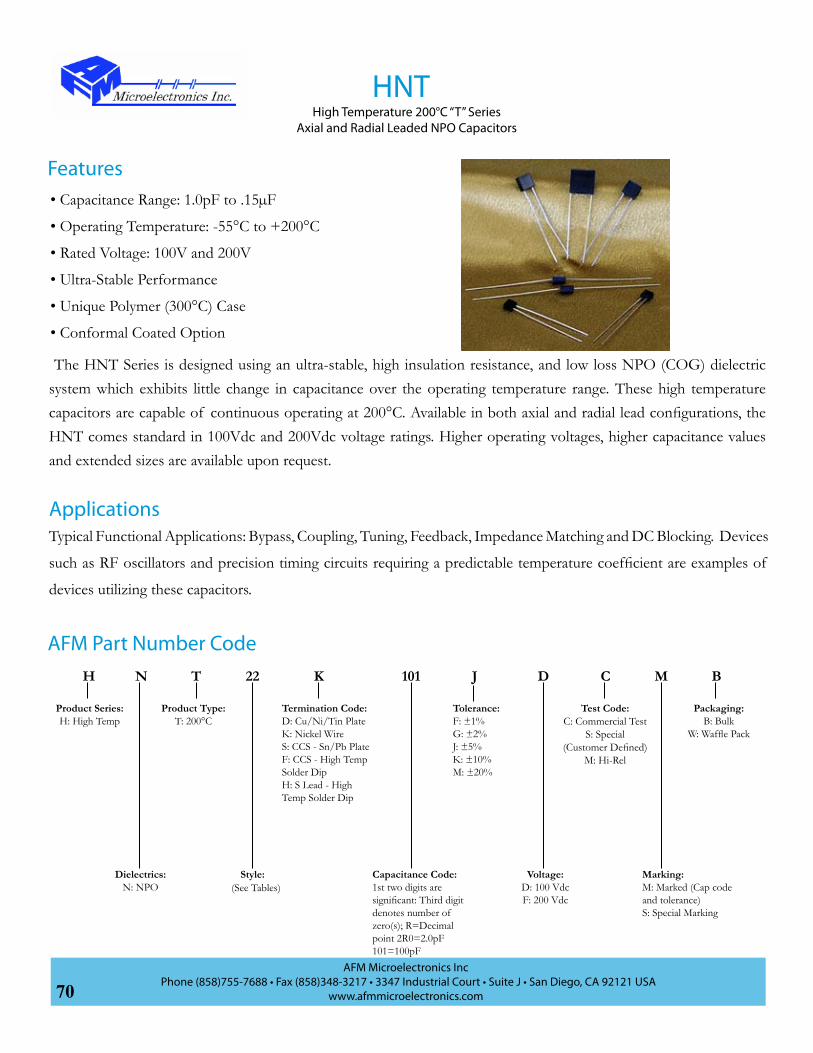
70AFM Microelectronics Inc
Phone (858)755-7688 • Fax (858)348-3217 • 3347 Industrial Court • Suite J • San Diego, CA 92121 USAwww.afmmicroelectronics.com
The HNT Series is designed using an ultra-stable, high insulation resistance, and low loss NPO (COG) dielectric system which exhibits little change in capacitance over the operating temperature range. These high temperature capacitors are capable of continuous operating at 200°C. Available in both axial and radial lead configurations, the HNT comes standard in 100Vdc and 200Vdc voltage ratings. Higher operating voltages, higher capacitance values and extended sizes are available upon request.
HNTHigh Temperature 200°C “T” Series
Axial and Radial Leaded NPO Capacitors
Typical Functional Applications: Bypass, Coupling, Tuning, Feedback, Impedance Matching and DC Blocking. Devices
such as RF oscillators and precision timing circuits requiring a predictable temperature coefficient are examples of
devices utilizing these capacitors.
Applications
• Capacitance Range: 1.0pF to .15µF
• Operating Temperature: -55°C to +200°C
• Rated Voltage: 100V and 200V
• Ultra-Stable Performance
• Unique Polymer (300°C) Case
• Conformal Coated Option
Features
AFM Part Number CodeH CK22TN DJ101 BM
Product Series:H: High Temp
Dielectrics:N: NPO
Product Type:T: 200°C
Style:
Termination Code:D: Cu/Ni/Tin PlateK: Nickel WireS: CCS - Sn/Pb PlateF: CCS - High Temp Solder DipH: S Lead - High Temp Solder Dip
Capacitance Code:1st two digits are significant: Third digit denotes number of zero(s); R=Decimal point 2R0=2.0pF101=100pF
Tolerance:F: ±1%G: ±2%J: ±5%K: ±10%M: ±20%
Voltage:D: 100 VdcF: 200 Vdc
Marking:M: Marked (Cap code and tolerance)S: Special Marking
Packaging:B: Bulk
W: Waffle Pack
(See Tables)
Test Code:C: Commercial Test
S: Special (Customer Defined)
M: Hi-Rel

71AFM Microelectronics Inc
Phone (858)755-7688 • Fax (858)348-3217 • 3347 Industrial Court • Suite J • San Diego, CA 92121 USAwww.afmmicroelectronics.com
Rad
ial L
eade
d N
P0 C
apac
itors
Style Capacitance Ranges Sizes (Max) Inches (mm) Lead Spacing ±0.30 (S)100 Vdc 200 Vdc Width
(W)Height
(H)Thickness
(T)Diameter
(D)Min Max Min Max
12 1.0pF .010µF 1.0pF 8200pF .200 (5.08)
.200 (5.08)
.100 (2.54)
.025 (.635)±.002 (.051)
.200 (5.08)
22 100pF .033µF 470pF .027µF .300 (7.62)
.300 (7.62)
.100 (2.54)
.025 (.635)±.002 (.051)
.200 (5.08)
25 270pF .047µF 560pF .039µF .300 (7.62)
.300 (7.62)
.150 (3.81)
.025 (.635)±.002 (.051)
.200 (5.08)
38 .010µF .100µF .010µF .100µF .500 (12.70)
.500 (12.70)
.250 (6.35)
.025 (.635)±.002 (.051)
.400 (10.16)
45 .010µF .150µF .010µF .120µF .675 (17.15)
.500 (12.70)
.250 (6.35)
.025 (.635)±.002 (.051)
.400 (10.16)
Axi
al L
eade
d N
P0 C
apac
itors
Diameter (D)
Length (L)
Lead Diameter (d)
10 12pF 1000pF 10pF 820pF .100 (2.54) .170 (4.32) .025 (.635)±.002 (.051)
17 16pF .010µF 16pF 8200pF .135 (3.43) .260 (6.60) .025 (.635)±.002 (.051)
30 1000pF .033µF 1000pF .027µF .155 (3.94) .400 (10.16) .025 (.635)±.002 (.051)
40 .010µF .047µF .010µF .039µF .200 (5.08) .500 (12.70) .025 (.635)±.002 (.051)
49 .010µF .100µF .010µF .082µF .375 (9.52) .750 (19.05) .025 (.635)±.002 (.051)
NPO Dielectric Capacitance Ranges and Size Information
TL
H
SD
1.25 Min
D
L
1.25”Min
d
HNTHigh Temperature 200°C “T” Series
Axial and Radial Leaded NPO Capacitors
100% of AFM’s high temperature capacitors undergo standard commercial testing. High reliability testing, customer SCD
test protocols, and optional extended tests are also available. For more information see testing pages at the end of the
catalog. AFM has the test facilities to perform electrical characterization measurements and burn in up to 300°C.
Testing and Burn In

72AFM Microelectronics Inc
Phone (858)755-7688 • Fax (858)348-3217 • 3347 Industrial Court • Suite J • San Diego, CA 92121 USAwww.afmmicroelectronics.com
Specification and Performance
Piezoelectric and Aging Effect: None
Temperature Range: -55°C to +200°C
Temperature Coefficient of Capacitance: 0±30ppm/°C
Dissipation Factor: 0.15% max at 200°C
Insulation Resistance (IR, at Rated Voltage):>104MΩ at 200°C or 100MΩµF Whichever is Less
Dielectric Withstand Voltage (DWV): 150% of Rated Voltage
Capacitance Drift: ±0.02% or ±0.02pF
Performance Curve
Temperature (°C)
-30
-20
-10
0
10
20
30
-20 20 60 100 140 180 220 260 300
Dissipation Factor
Dis
sipa
tion
Fact
or
Temperature (°C)
Capacitance vs. Temperature
0.00%
0.05%
0.10%
0.15%
0.20%
0.25%
0 40 80 120 160 200 240
Part
s Pe
r Mill
ion
HNTHigh Temperature 200°C “T” Series
Axial and Radial Leaded NPO Capacitors

73AFM Microelectronics Inc
Phone (858)755-7688 • Fax (858)348-3217 • 3347 Industrial Court • Suite J • San Diego, CA 92121 USAwww.afmmicroelectronics.com
The HXT Series is designed using a high insulation resistance, high dielectric constant barium titanate for high capacitance per unit volume. These high temperature capacitors are capable of continuous operating at 200°C. The dissipation factor of these capacitors improve five-fold at elevated temperature when compared to the dielectric loss at 25°C. The HXT comes standard with a 100Vdc and 200Vdc voltage rating. Higher voltage ratings are available upon request. See AFM’s VXT line of 200°C rated 1kV to 4kV capacitors.
HXTHigh Temperature 200°C “T” Series
Axial and Radial Leaded X7R Capacitors
Typical Functional Applications: Bypass, Coupling, Tuning, Feedback, Impedance Matching and DC Blocking. Devices
such as RF oscillators and precision timing circuits requiring a predictable temperature coefficient are examples of
devices utilizing these capacitors.
Applications
• Capacitance Range: 1000pF to 2.2µF
• Operating Temperature: -55°C to +200°C
• Rated Voltage: 100V and 200V
• Conformal Coated
• Unique High Temperature 300°C Polymer Case
Features
AFM Part Number CodeH CD22TX DJ101 BM
Product Series:H: High Temp
Dielectrics:X: X7R
Product Type:T: 200°C
Style: Capacitance Code:1st two digits are significant: Third digit denotes number of zero(s); R=Decimal point 2R0=2.0pF101=100pF
Tolerance:J: ±5%K: ±10%M: ±20%
Voltage:D: 100VF: 200V
Marking:M: Marked (Cap code and tolerance)S: Special Marking
Packaging:B: Bulk
W: Waffle Pack
(See Tables)
Test Code:C: Commercial Test
S: Special (Customer Defined)
M: Hi-Rel
Termination Code:D: Cu/Ni/Tin PlateK: Nickel WireS: CCS - Sn/Pb PlateF: CCS - High Temp Solder DipH: S Lead - High Temp Solder Dip

74AFM Microelectronics Inc
Phone (858)755-7688 • Fax (858)348-3217 • 3347 Industrial Court • Suite J • San Diego, CA 92121 USAwww.afmmicroelectronics.com
Rad
ial L
eade
d X
7R C
apac
itors
Style Capacitance Ranges Sizes (Max) Inches (mm) Lead Spacing ±0.30 (S)100 Vdc 200 Vdc Width
(W)Height
(H)Thickness
(T)Diameter
(D)Min Max Min Max
12 1000pF .027µF 1000pF .018µF .200 (5.08)
.200 (5.08)
.100 (2.54)
.025 (.635)±.002 (.051)
.200 (5.08)
22 1000pF .033µF 1000pF .120µF .300 (7.62)
.300 (7.62)
.100 (2.54)
.025 (.635)±.002 (.051)
.200 (5.08)
25 .010µF .047µF .010µF .150µF .300 (7.62)
.300 (7.62)
.150 (3.81)
.025 (.635)±.002 (.051)
.200 (5.08)
38 .010µF 1.5µF .010µF .500µF .500 (12.70)
.500 (12.70)
.250 (6.35)
.025 (.635)±.002 (.051)
.400 (10.16)
45 .100µF 2.2µF .100µF 1.0µF .675 (17.15)
.500 (12.70)
.250 (6.35)
.025 (.635)±.002 (.051)
.400 (10.16)
Axi
al L
eade
d X
7R C
apac
itors
Diameter (D)
Length (L)
Lead Diameter (d)
10 1000pF .022µF 1000pF .018µF .100 (2.54) .170 (4.32) .025 (.635)±.002 (.051)
17 1000pF .100µF 1000pF .027µF .135 (3.43) .260 (6.60) .025 (.635)±.002 (.051)
30 .010µF .180µF .015µF .056µF .155 (3.94) .400 (10.16) .025 (.635)±.002 (.051)
40 .010µF .560µF .027µF .390µF .200 (5.08) .500 (12.70) .025 (.635)±.002 (.051)
49 .100µF 1.0µF .100µF .680µF .375 (9.52) .750 (19.05) .025 (.635)±.002 (.051)
X7R Dielectric Capacitance Ranges and Size Information
TL
H
SD
1.25 Min
D
L
1.25”Min
d
HXTHigh Temperature 200°C “T” Series
Axial and Radial Leaded X7R Capacitors
100% of AFM’s high temperature capacitors undergo standard commercial testing. High reliability testing, customer SCD
test protocols, and optional extended tests are also available. For more information see testing pages at the end of the
catalog. AFM has the test facilities to perform electrical characterization measurements and burn in up to 300°C.
Testing and Burn In

75AFM Microelectronics Inc
Phone (858)755-7688 • Fax (858)348-3217 • 3347 Industrial Court • Suite J • San Diego, CA 92121 USAwww.afmmicroelectronics.com
Specification and Performance
Dielectric Absorption:<2.0% -55°C to 120°C None Exhibited Above 125°C (Paraelectric)
Temperature Range: -55°C to +200°C
Temperature Coefficient of Capacitance: +15% , -40%
Dissipation Factor: 1.2% at 25°C<2.0% at 200°C
Insulation Resistance (IR, at Rated Voltage):> 104MΩ at 25°C> 103MΩ at 200°C
Dielectric Withstand Voltage (DWV): 150% of Rated Voltage
Environmental and Mechanical: Capable of Meeting MIL-PRF-39014 Requirements
Performance Curve
HXTHigh Temperature 200°C “T” Series
Axial and Radial Leaded X7R Capacitors
-50
-40
-30
-20
-10
0
10
0 25 50 75 100 125 150 175 200 225 250 2750.00%
0.20%
0.40%
0.60%
0.80%
1.00%
1.20%
1.40%
0 50 100 150 200 250 300
Temperature Coefficient of Capacitance
Temperature °C
Dissipation Factor vs. Temperature
ESR
(Ohm
s)
% C
hang
e Ca
p
Temperature °C

76AFM Microelectronics Inc
Phone (858)755-7688 • Fax (858)348-3217 • 3347 Industrial Court • Suite J • San Diego, CA 92121 USAwww.afmmicroelectronics.com
MNT11 series is high temperature RF/Microwave capacitors incorporating an ultra-stable COG (NPO) dielectric system. These capacitors are designed for continuous operating at 200°C, are low loss, high insulation resistance, and exhibit little change in capacitance over the operating temperature range. The MNT11 Series is available with 100V with a rating up to 470pF and a 50V rating up to 1000pF. This Series can be supplied compliant to the EU’s RoHS standard.
MNT 11High Temperature 200°C “T” Series
COG (NPO) RF/Microwave Multilayer Capacitors
Typical Functional Applications: Bypass, Coupling, Tuning, Feedback, Impedance Matching and DC Blocking. Devices
such as RF oscillators and precision timing circuits requiring a predictable temperature coefficient are examples of
devices utilizing these capacitors.
Applications
• Capacitance Range: 0.1pF to 1000pF
• Operating Temperature: -55°C to +200°C
• Rated Voltage: 100V and 50V
• High Q
• Ultra-Stable Performance
• Low ESR/ESL
• High Self-Resonance
Features
AFM Part Number CodeM W11TN DJ101 BB
Product Series:M: High Frequency
Dielectrics:N: NPO
Product Type:T: 200°C
Chip Size:11: 0505
Termination Code:C: Pd/Ag TermG: Ag Term, Ni/Au PlatedN: Non Magnetic Term (Ag Term, Cu/Sn Plated)W: Ag Term, Ni Barrier, 90/10 Sn/Pb Plated
Capacitance Code:1st two digits are significant: Third digit denotes number of zero(s); R=Decimal point 2R0=2.0pF101=100pF
Tolerance:B: ±0.1pFC: ±0.25pFD: ±0.5pFF: ±1%G: ±2%J: ±5%K: ±10%M: ±20%
Voltage:B: 50Vdc
D: 100 Vdc
Marking:B: Not MarkedM: Marked (Cap code and tolerance)S: Special Marking
Packaging:B: Bulk
T: Tape & ReelW: Waffle Pack
C
Test Code:C: Commercial Test
S: Special (Customer Defined)
M: Hi-Rel

77AFM Microelectronics Inc
Phone (858)755-7688 • Fax (858)348-3217 • 3347 Industrial Court • Suite J • San Diego, CA 92121 USAwww.afmmicroelectronics.com
CAPCODE
CAP (pF)
TOL RATED WVdc
CAPCODE
CAP (pF)
TOL RATED WVdc
CAPCODE
CAP (pF)
TOL RATED WVdc
CAPCODE
CAP (pF)
TOL RATED WVdc
0R1 0.1B
100
2R4 2.4
B, C, D
100
200 20
F, G, J, K, M 100
151 150
F, G, J, K, M
100
0R2 0.2 2R7 2.7 220 22 161 1600R3 0.3
B, C3R0 3.0 240 24 181 180
0R4 0.4 3R3 3.3 270 27 201 2000R5 0.5
B, C, D
3R6 3.6 300 30 221 2200R6 0.6 3R9 3.9 330 33 241 2400R7 0.7 4R3 4.3 360 36 271 2700R8 0.8 4R7 4.7 390 39 301 3000R9 0.9 5R1 5.1 430 43 331 3301R0 1.0 5R6 5.6 470 47 361 3601R1 1.1 6R2 6.2 510 51 391 3901R2 1.2 6R8 6.8 560 56 431 4301R3 1.3 7R5 7.5 620 62 471 4701R4 1.4 8R2 8.2
B, C, J, K, M
680 68 511 510
50
1R5 1.5 9R1 9.1 750 75 561 560
1R6 1.6 100 10 820 82 621 620
1R7 1.7 110 11
F, G, J, K, M
910 91 681 6801R8 1.8 120 12 101 100 751 7501R9 1.9 130 13 111 110 821 8202R0 2.0 150 15 121 120 911 9102R1 2.1 160 16 131 130 102 10002R2 2.2 180 18
Standard Capacitance Values
Chip DimensionsLength .057in
(1.5mm)
Width .055in (1.4mm)
Thickness .055in(1.4mm)
Band .015in (0.38mm)
W
B
L
T
MNT 11High Temperature 200°C “T” Series
COG (NPO) RF/Microwave Multilayer Capacitors

78AFM Microelectronics Inc
Phone (858)755-7688 • Fax (858)348-3217 • 3347 Industrial Court • Suite J • San Diego, CA 92121 USAwww.afmmicroelectronics.com
Specification and Performance
Piezoelectric and Aging Effects: None
Temperature Range: -55°C to +200°C
Temperature Coefficient of Capacitance: 0±30ppm/°C
Quality Factor (Q):≤100pF at 1MHz >10k>100pF at 1MHz >2k
Insulation Resistance (IR, at Rated Voltage):>105MΩ at 25°C>104MΩ at 200°C
Dielectric Withstand Voltage (DWV): 250% of Rated Voltage
Capacitance Drift: ±0.02% or 0.02 pF
Performance Curve
MNT 11High Temperature 200°C “T” Series
COG (NPO) RF/Microwave Multilayer Capacitors
Size 12
Size 11
Q a
t1kH
z
0
2000
4000
6000
8000
10000
12000
14000
-40 -20 0 20 40 60 80 100 120 140 160 180 200
Self Resonant Frequency vs. Capacitance
Self
Reso
nant
Fre
quen
cy (G
Hz)
Q vs. Temperature
Capacitance (pF) Temperature (°C)

79AFM Microelectronics Inc
Phone (858)755-7688 • Fax (858)348-3217 • 3347 Industrial Court • Suite J • San Diego, CA 92121 USAwww.afmmicroelectronics.com
MNT12 series is high temperature RF/Microwave capacitors incorporating an ultra-stable COG (NPO) dielectric system. These capacitors are designed for continuous operating at 200°C, are low loss, high insulation resistance, and exhibit little change in capacitance over the operating temperature range. The MNT12 Series is available in voltages from 50 to 250 volts. High-reliability and burn-in testing is available as options. This Series can be supplied compliant to the EU’s RoHS standard.
MNT 12High Temperature 200°C “T” Series
COG (NPO) RF/Microwave Multilayer Capacitors
Typical Functional Applications: Bypass, Coupling, Tuning, Feedback, Impedance Matching and DC Blocking. Devices such as RF oscillators and precision timing circuits requiring a predictable temperature coefficient are examples of devices utilizing these capacitors.
Applications
• Capacitance Range: 0.1pF to 5100pF
• Operating Temperature: -55°C to 200°C
• Rated Voltage: 50V, 150V and 250V
• High Q
• Ultra-Stable Performance
• Low ESR/ESL
• High Self-Resonance
• Encapsulation Option for Leaded MNT 12 Series
• Lead Options (See Page 42)
Features
AFM Part Number CodeM W11TN DJ101 BB
Product Series:M: High Frequency
Dielectrics:N: NPO
Product Type:T: 200°C
Chip Size:11: 0505
Termination Code:C: Pd/Ag TermG: Ag Term, Ni/Au PlatedN: Non Magnetic Term (Ag Term, Cu/Sn Plated)W: Ag Term, Ni Barrier, 90/10 Sn/Pb Plated
Capacitance Code:1st two digits are significant: Third digit denotes number of zero(s); R=Decimal point 2R0=2.0pF101=100pF
Tolerance:B: ±0.1pFC: ±0.25pFD: ±0.5pFF: ±1%G: ±2%J: ±5%K: ±10%M: ±20%
Voltage:B: 50Vdc
D: 100 Vdc
Marking:B: Not MarkedM: Marked (Cap code and tolerance)S: Special Marking
Packaging:B: Bulk
T: Tape & ReelW: Waffle Pack
C
Test Code:C: Commercial Test
S: Special (Customer Defined)
M: Hi-Rel

80AFM Microelectronics Inc
Phone (858)755-7688 • Fax (858)348-3217 • 3347 Industrial Court • Suite J • San Diego, CA 92121 USAwww.afmmicroelectronics.com
Standard Capacitance Values
Chip DimensionsLength .110in
(2.79mm)
Width .110in (2.79mm)
Thickness .102in(2.59mm)
Band .015in (0.38mm)
W
B
L
T
MNT 12High Temperature 200°C “T” Series
COG (NPO) RF/Microwave Multilayer Capacitors
CAPCODE
CAP (pF) TOL
RATED WVdc CAPCODE
CAP (pF) TOL
RATED WVdc CAPCODE
CAP (pF) TOL
RATED WVdc CAPCODE
CAP (pF) TOL
RATED WVdc
STD.* EXT.* STD. EXT. STD. EXT. STD. EXT.
0R1 0.1B
500 1500
3R3 3.3
B, C, D
500 1500
360 36
F, G, J, K, M
500
1500
391 390
F, G, J, K, M
200
N/A
0R2 0.2 3R6 3.6 390 39 431 430
0R3 0.3B, C
3R9 3.9 430 43 471 470
0R4 0.4 4R3 4.3 470 47 511 5101000R5 0.5
B, C, D
4R7 4.7 510 51
1000
561 5600R6 0.6 5R1 5.1 560 56 621 6200R7 0.7 5R6 5.6 620 62 681 680
50
0R8 0.8 6R2 6.2 680 68 751 7500R9 0.9 6R8 6.8
B, C, J, K, M
750 75 821 8201R0 1.0 7R5 7.5 820 82 911 9101R1 1.1 8R2 8.2 910 91 102 10001R2 1.2 9R1 9.1 101 100 112 11001R3 1.3 100 10
F, G, J, K, M
111 110
300
122 12001R4 1.4 110 11 121 120 152 15001R5 1.5 120 12 131 130 182 18001R6 1.6 130 13 151 150 222 22001R7 1.7 150 15 161 160 272 27001R8 1.8 160 16 181 180 302 30001R9 1.9 180 18 201 200 332 33002R0 2.0 200 20 221 220
200 N/A
392 39002R1 2.1 220 22 241 240 472 47002R2 2.2 240 24 271 270 512 51002R4 2.4 270 27 301 3002R7 2.7 300 30 331 3303R0 3.0 330 33 361 360
*STD.:Standard Voltage; EXT.: Extended Voltage

81AFM Microelectronics Inc
Phone (858)755-7688 • Fax (858)348-3217 • 3347 Industrial Court • Suite J • San Diego, CA 92121 USAwww.afmmicroelectronics.com
Specification and Performance
Piezoelectric and Aging Effects: None
Temperature Range: -55°C to +200°C
Temperature Coefficient of Capacitance: 0±30ppm/°C
Quality Factor (Q):<200pF at 1 MHz >10k≥200pF to 1000pF at 1 MHz >1k
Insulation Resistance (IR, at Rated Voltage):>105MΩ at 25°C>104MΩ at 200°C
Dielectric Withstand Voltage (DWV): 200% of Rated Voltage
Capacitance Drift: ±0.02% or 0.02 pF
Performance Curve
MNT 12High Temperature 200°C “T” Series
COG (NPO) RF/Microwave Multilayer Capacitors
Capacitance (pF)
Self Resonant Frequency vs. Capacitance
Self
Reso
nant
Fre
quen
cy (G
Hz)
Temperature °C
Q a
t1kH
z
0
2000
4000
6000
8000
10000
12000
14000
-40 -20 0 20 40 60 80 100 120 140 160 180 200
Q vs. Temperature

82AFM Microelectronics Inc
Phone (858)755-7688 • Fax (858)348-3217 • 3347 Industrial Court • Suite J • San Diego, CA 92121 USAwww.afmmicroelectronics.com
The MPT series is high temperature, high frequency capacitors that is now available with an extended operating temperature up to 200°C. The MPT12 Series is available with a rated voltage from 50 volts to 300 volts based on capacitance value. Leaded capacitors are available as AFM HPT Series and are encapsulated to protect capacitors from contaminants that may be experienced due to severe environmental conditions. This Series can be supplied compliant to the EU’s RoHS standard.
MPT 12High Temperature 200°C “T” Series
Porcelain RF/Microwave Multilayer Capacitors
Typical functional applications include oil, natural gas and geothermal exploration equipment; high temperature engine
controls and sensors and any other applications having severe environments.
Applications
• Capacitance Range: 0.1pF to 1000pF
• Operating Temperature: -55°C to 200°C
• Rated Voltage: 50V to 300V
• Low Noise
• Low ESR/ESL
• High Self-Resonance
Features
AFM Part Number CodeM CW12TP BJ101 BB
Product Series:M: High Frequency
Dielectrics:P: Porcelain
Product Type:T: 200°C
Chip Size:12: 1111
Capacitance Code:1st two digits are significant: Third digit denotes number of zero(s); R=Decimal point 2R0=2.0pF101=100pF
Tolerance:B: ± 0.1pFC: ± 0.25pFD: ±0.5pFF: ±1%G: ±2%J: ±5%K: ±10%M: ±20%
Voltage:B: 50 VdcD: 100 VdcF: 200 VdcH: 300Vdc
Marking:B: Not MarkedM: Marked (Cap code and tolerance)S: Special Marking
Packaging:B: Bulk
T: Tape & ReelW: Waffle Pack
Test Code:C: Commercial Test
S: Special (Customer Defined)
M: Hi-Rel
Termination Code:A: Axial Wire*C: Pd/Ag TermG: Ag Term, Ni/Au PlatedS: High Temp Solder DipT: Ag Term, Ni/100% Sn Plated (Pb Free)W: Ag Term, Ni Barrier, 90/10 Sn/Pb Plated
*Wire is CCS with High Temp Solder Dip

83AFM Microelectronics Inc
Phone (858)755-7688 • Fax (858)348-3217 • 3347 Industrial Court • Suite J • San Diego, CA 92121 USAwww.afmmicroelectronics.com
Standard Capacitance Values
Chip DimensionsLength .110in
(2.79mm)
Width .110in (2.79mm)
Thickness .102in(2.59mm)
Band .015in (0.38mm)
W
B
L
T
MPT 12
CAPCODE
CAP (pF)
TOL RATED WVdc
CAPCODE
CAP (pF)
TOL RATED WVdc
CAPCODE
CAP (pF)
TOL RATED WVdc
CAPCODE
CAP (pF) TOL RATED WVdc
0R1 0.1B
300
2R4 2.4
F, G, J, K, M
300
180 18
F, G, J, K, M
300
131 130
F, G, J, K, M
2000R2 0.2 2R7 2.7 200 20 151 1500R3 0.3
B, C3R0 3.0 220 22 161 160
0R4 0.4 3R3 3.3 240 24 181 1800R5 0.5
B, C, D
3R6 3.6 270 27 201 2000R6 0.6 3R9 3.9 300 30 221 220
100
0R7 0.7 4R3 4.3 330 33 241 2400R8 0.8 4R7 4.7 360 36 271 2700R9 0.9 5R1 5.1 390 39 301 3001R0 1.0 5R6 5.6 430 43 331 3301R1 1.1 6R2 6.2 470 47 361 3601R2 1.2 6R8 6.8 510 51 391 3901R3 1.3 7R5 7.5 560 56 431 4301R4 1.4 8R2 8.2 620 62 471 4701R5 1.5 9R1 9.1 680 68 511 5101R6 1.6 100 10 750 75 561 560
50
1R7 1.7 110 11 820 82 621 6201R8 1.8 120 12 910 91 681 6801R9 1.9 130 13 101 100 751 7502R0 2.0 150 15 111 110 821 820
2R1 2.1 160 16 121 120200
911 9102R2 2.2 102 1000
High Temperature 200°C “T” Series Porcelain RF/Microwave Multilayer Capacitors

84AFM Microelectronics Inc
Phone (858)755-7688 • Fax (858)348-3217 • 3347 Industrial Court • Suite J • San Diego, CA 92121 USAwww.afmmicroelectronics.com
Specification and Performance
Piezoelectric and Aging Effects: None
Temperature Range: -55°C to +200°C
Temperature Coefficient of Capacitance: +90±30ppm/°C
Insulation Resistance (IR, at Rated Voltage):>106MΩ at 25°C>105MΩ at 125°C>104MΩ at 200°C
Dielectric Withstand Voltage (DWV): 250% of Rated Voltage
Capacitance Drift: ±0.02% or 0.02 pF
Performance Curve
MPT 12
ESR vs. Capacitance
Equi
vale
nt S
erie
s Re
sist
ance
(ohm
s)
Capacitance (pF)
Q vs. Capacitance
Capacitance (pF)
Q F
acto
r
Size 12 Size 12
Size 11Size 11
Self
Reso
nant
Fre
quen
cy (G
Hz)
Capacitance (pF)
Resonance
High Temperature 200°C “T” Series Porcelain RF/Microwave Multilayer Capacitors
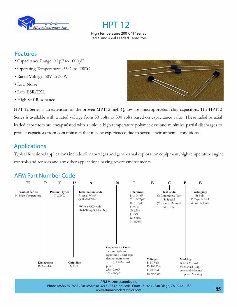
85AFM Microelectronics Inc
Phone (858)755-7688 • Fax (858)348-3217 • 3347 Industrial Court • Suite J • San Diego, CA 92121 USAwww.afmmicroelectronics.com
HPT 12 Series is an extension of the proven MPT12 high Q, low loss microporcelain chip capacitors. The HPT12
Series is available with a rated voltage from 50 volts to 300 volts based on capacitance value. These radial or axial
leaded capacitors are encapsulated with a unique high temperature polymer case and minimize partial discharges to
protect capacitors from contaminants that may be experienced due to severe environmental conditions.
HPT 12High Temperature 200°C “T” SeriesRadial and Axial Leaded Capacitors
Typical functional applications include oil, natural gas and geothermal exploration equipment; high temperature engine
controls and sensors and any other applications having severe environments.
Applications
• Capacitance Range: 0.1pF to 1000pF
• Operating Temperature: -55°C to 200°C
• Rated Voltage: 50V to 300V
• Low Noise
• Low ESR/ESL
• High Self-Resonance
Features
AFM Part Number CodeH CA12TP BJ101 BB
Product Series:H: High Temperature
Dielectrics:P: Porcelain
Product Type:T: 200°C
Chip Size:12: 1111
Capacitance Code:1st two digits are significant: Third digit denotes number of zero(s); R=Decimal point 2R0=2.0pF101=100pF
Tolerance:B: ± 0.1pFC: ± 0.25pFD: ±0.5pFF: ±1%G: ±2%J: ±5%K: ±10%M: ±20%
Voltage:B: 50 VdcD: 100 VdcF: 200 VdcH: 300Vdc
Marking:B: Not MarkedM: Marked (Cap code and tolerance)S: Special Marking
Packaging:B: Bulk
T: Tape & ReelW: Waffle Pack
Test Code:C: Commercial Test
S: Special (Customer Defined)
M: Hi-Rel
Termination Code:A: Axial Wire*Q: Radial Wire*
*Wire is CCS with High Temp Solder Dip

86AFM Microelectronics Inc
Phone (858)755-7688 • Fax (858)348-3217 • 3347 Industrial Court • Suite J • San Diego, CA 92121 USAwww.afmmicroelectronics.com
.240 (6.10)
.160 (4.06)
1.25 Min(31.75)
dS
.150(3.81)
.150(3.81)
.240 (6.10)
.160 (4.06)
Ll
d
HPT 12High Temperature 200°C “T” SeriesRadial and Axial Leaded Capacitors
Chip Dimensions:
Standard Capacitance ValuesCAP
CODECAP (pF)
TOL RATED WVdc
CAPCODE
CAP (pF)
TOL RATED WVdc
CAPCODE
CAP (pF)
TOL RATED WVdc
CAPCODE
CAP (pF) TOL RATED WVdc
0R1 0.1B
300
2R4 2.4
F, G, J, K, M
300
180 18
F, G, J, K, M
300
131 130
F, G, J, K, M
2000R2 0.2 2R7 2.7 200 20 151 1500R3 0.3
B, C3R0 3.0 220 22 161 160
0R4 0.4 3R3 3.3 240 24 181 1800R5 0.5
B, C, D
3R6 3.6 270 27 201 2000R6 0.6 3R9 3.9 300 30 221 220
100
0R7 0.7 4R3 4.3 330 33 241 2400R8 0.8 4R7 4.7 360 36 271 2700R9 0.9 5R1 5.1 390 39 301 3001R0 1.0 5R6 5.6 430 43 331 3301R1 1.1 6R2 6.2 470 47 361 3601R2 1.2 6R8 6.8 510 51 391 3901R3 1.3 7R5 7.5 560 56 431 4301R4 1.4 8R2 8.2 620 62 471 4701R5 1.5 9R1 9.1 680 68 511 5101R6 1.6 100 10 750 75 561 560
50
1R7 1.7 110 11 820 82 621 6201R8 1.8 120 12 910 91 681 6801R9 1.9 130 13 101 100 751 7502R0 2.0 150 15 111 110 821 820
2R1 2.1 160 16 121 120 200 911 910
2R2 2.2 102 1000
Specification and PerformancePiezoelectric and Aging Effects: None
Temperature Range: -55°C to +200°C
Temperature Coefficient of Capacitance: +90±30ppm/°C
Insulation Resistance (IR, at Rated Voltage): >106MΩ at 25°C; >105MΩ at 125°C; >104MΩ at 200°C
Dielectric Withstand Voltage (DWV): 250% of Rated Voltage
Capacitance Drift: ±0.02% or 0.02 pF
Radial Lead Axial Lead

87AFM Microelectronics Inc
Phone (858)755-7688 • Fax (858)348-3217 • 3347 Industrial Court • Suite J • San Diego, CA 92121 USAwww.afmmicroelectronics.com
SNT / SXTHigh Voltage, High Reliability 200°C “T” Series
DC COG (NPO)/X7R Ceramic Chip Surface Mount Capacitors
• Capacitance Range: 10pF to 2.7µF
• Operating Temperature Range: -55°C to 200°C
• Voltage Range: 500V to 5kV
• COG (NPO) and X7R DielectricSNT/SXT series is high voltage multilayer ceramic surface mount capacitors for use in severe environment with operating temperatures up to 200°C. These ruggedized capacitors are encapsulated with unique polymer/ceramic system which enables them to operate reliably in high shock and vibrational environment and also to prevent corona (partial discharges) during operation. Each capacitor is 100% tested physically and electrically* and can be screened to Group A and B performance criteria as defined in MIL-PRF-49467. AFM has extensive electrical and environmental test capability with component burn-in and characterization up to 300°C. Custom designs, extended thickness and test protocols to customer Source Control Drawings (SCD’s) are available on request.
Typical applications include filtering of high voltage power supplies, high voltage multipliers, transient protection and noise suppression.*See Test Options Pages at the End of the Catalog.
S L15TN LJ101 BM
Product Series:S: Surface Mount
Dielectrics:N: NPOX: X7R
Product Type:T: 200°C
Size:(See Table)
Termination Code:J: Ag Plated CuL: Ag Plated Cu
Capacitance Code:1st two digits are significant: Third digit denotes number of zero(s); R=Decimal point 2R0=2.0pF101=100pF
Tolerance:J: ±5%K: ±10%M: ±20%
Voltage:J: 500 VdcL: 1000 VdcO: 2000 VdcQ: 3000 VdcS: 4000 VdcT: 5000 Vdc
Marking:M: Marked (per description)S: Special Marking
Packaging:B: BulkW: Waffle Pack
C
Test Code:C: Commercial Test
S: Special (Customer Defined)
M: Hi-Rel
Features
Aplications:
AFM Part Number Code

88AFM Microelectronics Inc
Phone (858)755-7688 • Fax (858)348-3217 • 3347 Industrial Court • Suite J • San Diego, CA 92121 USAwww.afmmicroelectronics.com
SNT / SXTHigh Voltage, High Reliability 200°C “T” Series
DC COG (NPO)/X7R Ceramic Chip Surface Mount Capacitors
Style Length (L)Inches (mm)
Width (W)Inches (mm)
Thickness (T)Max Inches (mm)
Tab (B)Inches (mm)
15 .225 ±.015 (5.72 ±.38) .225 ±.015 (5.72 ±.38) .160 (4.06) .100 (2.54)20 .275 ±.015 (6.99 ±.38) .275 ±.015 (6.99 ±.38) .210 (5.33) .100 (2.54)25 .330 ±.015 (8.38 ±.38) .255 ±.015 (6.48 ±.38) .210 (5.33) .100 (2.54)35 .450 ±.020 (11.43 ±.51) .370 ± .020 (9.40 ±.51) .255 (6.48) .200 (5.08)40 .500 ±.020 (12.70±.51) .500 ±.020 (12.70±.51) .255 (6.48) .200 (5.08)45 .550 ±.020 (13.97±.76) .500 ±.020 (12.70±.51) .255 (6.48) .300 (7.62)55 .650 ±.030 (16.51±.76) .600 ± .030 (15.24±.51) .255 (6.48) .400 (10.16)65 .780 ±.030 (19.81±.76) .700 ± .030 (17.78±.76) .260 (6.60) .500 (12.70)70 .800 ±.030 (20.32±.76) .400 ±.030 (10.16±.76) .260 (6.60) .200 (5.08)90 1.00 ±.030 (25.40±.76) .500 ±.020 (12.70±.51) .260 (6.60) .300 (7.62)95 1.30 ±.030 (33.02±.76) .600 ±.030 (15.24±.76) .260 (6.60) .400 (10.16)99 1.50 ±.030 (38.1±.76) .700 ± .030 (17.78±.76) .260 (6.60) .500 (12.70)
Capacitor Dimensions and Tolerances
Outline Drawings and Lead Configurations
L
W
SNT99AFM225K1kV0511
.060/.120(1.52/3.05)
B± 0.010
“L” Lead
.030 ± .010(0.76 / 0.25)
T
“J” Lead
.080 / .120 (2.03 /3.05).030 / .050
(0.76 / 1.27) Style 15, 20, 22
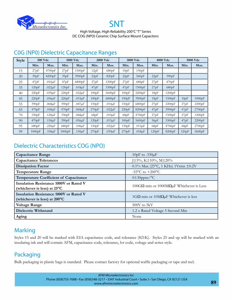
89AFM Microelectronics Inc
Phone (858)755-7688 • Fax (858)348-3217 • 3347 Industrial Court • Suite J • San Diego, CA 92121 USAwww.afmmicroelectronics.com
Style 500 Vdc 1000 Vdc 2000 Vdc 3000 Vdc 4000 Vdc 5000 VdcMin. Max. Min. Max. Min. Max. Min. Max. Min. Max. Min. Max.
15 27pF 4700pF 27pF 1500pF 12pF 680pF 10pF 150pF
20 39pF 8200pF 39pF 3900pF 22pF 820pF 22pF 560pF 22pF 390pF
25 47pF .010µF 47pF 6800pF 27pF 1200pF 27pF 680pF 27pF 470pF
35 120pF .022µF 120pF .018µF 47pF 3300pF 47pF 1500pF 27pF 680pF
40 220pF .039µF 220pF .022µF 100pF 5600pF 100pF 2200pF 18pF 1200pF
45 220pF .056µF 220pF .033µF 100pF 6800pF 100pF 3900pF 18pF 1500pF 18pF 1000pF
55 390pF .068µF 390pF .047µF 150pF .010µF 150pF 6800pF 27pF 2200pF 27pF 2200pF
65 470pF .100µF 470pF .068µF 270pF .022µF 220pF 8200pF 47pF 3900pF 47pF 2700pF
70 330pF .120µF 330pF .068µF 68pF .010µF 68pF 4700pF 27pF 1500pF 27pF 1200pF
90 470pF .150µF 390pF .056µF 120pF .015µF 100pF 5600pF 56pF 3300pF 47pF 2200pF
95 680pF .220µF 680pF .100µF 150pF .022µF 150pF .012µF 68pF 4700pF 68pF 2700pF
99 1000pF .330µF 1000pF .150µF 270pF .039µF 270pF .018µF 120pF 8200pF 120pF 5600pF
C0G (NP0) Dielectric Capacitance Ranges
Capacitance Range 10pF to .330µFCapacitance Tolerances J±5%, K±10%, M±20%Dissipation Factor 0.1% Max (25°C, 1 KHz) 1Vrms ±0.2VTemperature Range -55°C to +200°CTemperature Coefficient of Capacitance 0±30ppm/°CInsulation Resistance 1000V or Rated V (whichever is less) at 25°C 100GΩ min or 1000MΩµF Whichever is Less
Insulation Resistance 1000V or Rated V (whichever is less) at 200°C 1GΩ min or 10MΩµF Whichever is less
Voltage Range 500V to 5kVDielectric Withstand 1.2 x Rated Voltage 5 Second MinAging None
Styles 15 and 20 will be marked with EIA capacitance code, and tolerance (821K). Styles 25 and up will be marked with an insulating ink and will contain AFM, capacitance code, tolerance, lot code, voltage and series style.
Marking
PackagingBulk packaging in plastic bags is standard. Please contact factory for optional waffle packaging or tape and reel.
Dielectric Characteristics COG (NPO)
SNTHigh Voltage, High Reliability 200°C “T” Series
DC COG (NPO) Ceramic Chip Surface Mount Capacitors

90AFM Microelectronics Inc
Phone (858)755-7688 • Fax (858)348-3217 • 3347 Industrial Court • Suite J • San Diego, CA 92121 USAwww.afmmicroelectronics.com
SXTHigh Voltage, High Reliability 200°C “T” Series
DC X7R Ceramic Chip Surface Mount Capacitors
Style 500 Vdc 1000 Vdc 2000 Vdc 3000 Vdc 4000 Vdc 5000 VdcMin. Max. Min. Max. Min. Max. Min. Max. Min. Max. Min. Max.
15 680pF .047µF 680pF .012µF 270pF 2700pF 100pF 1200pF
20 1200pF .100µF 1200pF .039µF 560pF 6800pF 560pF 2700pF
25 1200pF .120µF 1200pF .056µF 680pF .012µF 680pF 4700pF
35 3300pF .390µF 3300pF .180µF 1200pF .027µF 1200pF .010µF 270pF 4700pF
40 6800pF .470µF 6800pF .220µF 2700pF .033µF 2700pF .012µF 470pF 6800pF
45 6800pF .680µF 6800pF .270µF 2700pF .047µF 2700pF .018µF 470pF 6800pF 470pF 4700pF
55 .010µF 1.00µF .010µF .470µF 3900pF .082µF 3900pF .027µF 680pF .010µF 680pF 6800pF
65 .015µF 1.50µF .015µF .560µF 6800pF .120µF 6800pF .047µF 1200pF .012µF 1200pF .010µF
70 .010µF 1.00µF .010µF .270µF 1800pF .056µF 1800pF .018µF 680pF 8200pF 680pF 4700pF
90 .012µF 1.50µF .012µF .470µF 3300pF .120µF 3300pF .033µF 1200pF .012µF 1200pF .012µF
95 .018µF 2.00µF .018µF .820µF 4700pF .180µF 3900pF .056µF 2200pF .027µF 2200pF .015µF
99 .027µF 2.70µF .027µF 1.50µF 8200pF .270µF 5600pF .082µF 3300pF .039µF 3300pF .018µF
X7R Dielectric Capacitance Ranges
Capacitance Range 100pF to 2.7µFCapacitance Tolerances J±5%, K±10%, M±20%Dissipation Factor 2.5% Max (25°C, 1 KHz) 1Vrms ±0.2V, <.20% @ 200°CTemperature Range -55°C to +200°CTemperature Coefficient of Capacitance +15%, -40% to 200°CInsulation Resistance 1000V or Rated V (whichever is less) at 25°C 10GΩ Min or 100MΩµF Whichever is Less
Insulation Resistance 1000V or Rated V (whichever is less) at 200°C 1GΩ Min or 10MΩµF Whichever is Less
Voltage Range 500V to 5kV (See Table)Dielectric Withstand 1.2 x rated Voltage 5 Second MinAging None
Bulk packaging in plastic bags is standard. Please contact factory for optional waffle packaging or tape and reel.
Marking
Packaging
Dielectric Characteristics X7R
Styles 15 and 20 will be marked with EIA capacitance code, and tolerance (821K). Styles 25 and up will be marked with an insulating ink and will contain AFM, Capacitance code, tolerance, lot code, voltage and series style.

91AFM Microelectronics Inc
Phone (858)755-7688 • Fax (858)348-3217 • 3347 Industrial Court • Suite J • San Diego, CA 92121 USAwww.afmmicroelectronics.com
VNT/VXTHigh Voltage, High Temperature 200°C “T” Series
Radial Leaded COG (NPO)/X7R Capacitors
• Capacitance Range: 12pF to .56µF
• Operating Temperature: -55°C to +200°C
• Rated Voltage: 500V to 4kV
• High Reliability
• Conformal Coated
• 200°C Burn-In Testing
VNT/VXT series is high voltage, high temperature capacitors which are based
on AFM’s industry proven high temperature HNT/HXT Series of capacitors. These capacitors have operating
voltage ratings of 500 volts up to 4000 volts. The VNT/VXT Series is designed using a high insulation resistance,
high dielectric constant barium titanate dielectric system.
AFM Part Number Code
Typical Functional Applications: Bypass, Coupling, Tuning, Feedback, Impedance Matching and DC Blocking. Devices
such as RF oscillators and precision timing circuits requiring a predictable temperature coefficient are examples of
devices utilizing these capacitors.
V CK15TN LJ101 BM
Product Series:V: High Voltage
Dielectrics:N: NPOX: X7R
Product Type:T: 200°C
Size:(See Table)
Capacitance Code:1st two digits are significant: Third digit denotes number of zero(s); R=Decimal point 2R0=2.0pF101=100pF
Tolerance:G: ±2%J: ±5%K: ±10%M: ±20%
Voltage:J: 500 VdcL: 1000 VdcO: 2000 VdcQ: 3000 VdcS: 4000 Vdc
Marking:M: Marked
S: Special Marking
Packaging:B: Bulk
W: Waffle Pack
Test Code:C: Commercial Test
S: Special (Customer Defined)
M: Hi-Rel
Termination Code:D: Cu/Ni/Tin PlateK: Nickel WireS: CCS - Sn/Pb PlateF: CCS - High Temp Solder DipH: S Lead - High Temp Solder Dip
Size 15 & 25
122kAFM
Date Code
VNT55N562K2kVAFM
Date Code
Size 35 & Up
Features
Aplications

92AFM Microelectronics Inc
Phone (858)755-7688 • Fax (858)348-3217 • 3347 Industrial Court • Suite J • San Diego, CA 92121 USAwww.afmmicroelectronics.com
VNTHigh Voltage, High Temperature 200°C “T” Series
Radial Leaded COG (NPO) Capacitors
Style VNT 15 VNT 25 VNT 35 VNT 45
Dim
ensi
ons
W Max .250 (6.35) .320 (8.13) .420 (10.67) .520 (13.21)
H Max .220 (5.59) .300 (7.62) .400 (10.16) .500 (12.70)
T Max .150 (3.81) .250 (6.35) .250 (6.35) .300 (7.62)
D ± .002 (.0508)
.025 (.635) .025 (.635) .025 (.635) .025 (.635)
S .170 (4.32) .200 (5.08) .300 (7.62) .400 (10.16)
Cap
acita
nce
Ran
ge (p
F)
Vdc 500 1kV 2kV 500 1kV 2kV 3kV 500 1kV 2kV 3kV 500 1kV 2kV 3kV12
1518
2228
3339
4756
6882
100120
150180
220270
330390
470560
680820
10001200
15001800
22002700
3300
39004700
56006800
W T
DS
H

93AFM Microelectronics Inc
Phone (858)755-7688 • Fax (858)348-3217 • 3347 Industrial Court • Suite J • San Diego, CA 92121 USAwww.afmmicroelectronics.com
Style VNT 55 VNT 65 VNT 71
Dim
ensi
ons
W Max .620 (15.75) .720 (18.29) .820 (20.83)
H Max .600 (15.24) .700 (17.78) .700 (17.78)
T Max .300 (7.62) .300 (7.62) .350 (8.89)
D ± .002 (.0508)
.025 (.635) .025 (.635) .025 (.635)
S .500 (12.70) .600 (15.24) .700 (17.78)
Vdc 500 1kV 2kV 3kV 4kV 500 1kV 2kV 3kV 4kV 500 1kV 2kV 3kV 4kV
Cap
acita
nce
Ran
ge
1000pF1200pF
1800pF2200pF
2700pF3300pF
3900pF4700pF
5600pF6800pF
8200pF.01µF
.012µF.015µF
.018µF.022µF
.027µF.033µF
Capacitance Range 12pF to .180µFCapacitance Tolerances G±2%, J±5%, K±10%, M±20%Dissipation Factor 0.1% Max (25°C, 1 KHz) 1Vrms ±0.2VTemperature Range -55°C to +200°CTemperature Coefficient of Capacitance 0±30ppm/°CInsulation Resistance 1000V or Rated V (whichever is less) at 25°C 100GΩ min or 1000MΩµF Whichever is Less
Insulation Resistance 1000V or Rated V (whichever is less) at 200°C 1GΩ min or 10MΩµF Whichever is Less
Voltage Range 500V to 4kV (See Table)Dielectric Withstand 1.2 x Rated Voltage 5 Second MinAging None
Dielectric Characteristics COG (NPO)
VNTHigh Voltage, High Temperature 200°C “T” Series
Radial Leaded COG (NPO) Capacitors
W T
DS
H

94AFM Microelectronics Inc
Phone (858)755-7688 • Fax (858)348-3217 • 3347 Industrial Court • Suite J • San Diego, CA 92121 USAwww.afmmicroelectronics.com
Style VXT 15 VXT 25 VXT 35 VXT 45
Dim
ensi
ons
W Max .250 (6.35) .320 (8.13) .420 (10.67) .520 (13.21)
H Max .220 (5.59) .300 (7.62) .400 (10.16) .500 (12.70)
T Max .150 (3.81) .250 (6.35) .250 (6.35) .300 (7.62)
D ± .002 (.0508)
.025 (.635) .025 (.635) .025 (.635) .025 (.635)
S .170 (4.32) .200 (5.08) .300 (7.62) .400 (10.16)
Voltage dc 500 1kV 2kV 500 1kV 2kV 3kV 500 1kV 2kV 3kV 500 1kV 2kV 3kV
Cap
acita
nce
Ran
ge
680pF820pF
1000pF1200pF
1500pF1800pF
2200pF2700pF
3300pF3900pF
4700pF5600pF
6800pF8200pF
.01µF.012µF
.015µF.018µF
.022µF.027µF
.033µF.039µF
.047µF.056µF
.068µF.082µF
.100µF.120µF
.150µF.180µF
VXTHigh Voltage, High Temperature 200°C “T” Series
Radial Leaded X7R Capacitors
W T
DS
H

95AFM Microelectronics Inc
Phone (858)755-7688 • Fax (858)348-3217 • 3347 Industrial Court • Suite J • San Diego, CA 92121 USAwww.afmmicroelectronics.com
VXTHigh Voltage, High Temperature 200°C “T” Series
Radial Leaded X7R Capacitors
Style VXT 55 VXT 65 VXT 71
Dim
ensi
ons W Max .620 (15.75) .720 (18.29) .820 (20.83)
H Max .600 (15.24) .700 (17.78) .700 (17.78)
T Max .300 (7.62) .300 (7.62) .350 (8.89)
D ± .002 (.0508) .025 (.635) .025 (.635) .025 (.635)
S .500 (12.7) .600 (15.24) .700 (17.78)
Voltage dc 500 1kV 2kV 3kV 4kV 500 1kV 2kV 3kV 4kV 500 1kV 2kV 3kV 4kV
Cap
acita
nce
Ran
ge (p
F)
.012.015
.018.022
.027.033
.039.047
.056.068
.082.100
.120.150
.180.220
.270.330
.390.470
.560.680
Capacitance Range 680pF to .56µFCapacitance Tolerances J±5%, K±10%, M±20%Dissipation Factor 2.5% Max (25°C, 1 KHz) 1Vrms ±0.2V, <.20% @200°CTemperature Range -55°C to +200°CTemperature Coefficient of Capacitance +15%, -40% to 200°CInsulation Resistance 1000V or Rated V (whichever is less) at 25°C 10GΩ min or 100MΩµF Whichever is Less
Insulation Resistance 1000V or Rated V (whichever is less) at 200°C 1GΩ min or 10MΩµF Whichever is Less
Voltage Range 500V to 5kV (See Table)Dielectric Withstand 1.2 x Rated Voltage 5 Second MinAging None
Dielectric Characteristics X7R
W T
DS
H

96AFM Microelectronics Inc
Phone (858)755-7688 • Fax (858)348-3217 • 3347 Industrial Court • Suite J • San Diego, CA 92121 USAwww.afmmicroelectronics.com
SNR / SXR
• Capacitance Range: 10pF to 5.6µF
• Operating Temperature Range: -55°C to 125°C
• Voltage Range: 500 Volt to 10KV
• COG (NPO) and X7R Dielectric
SNR/SXR series is high voltage multilayer ceramic chip capacitors for use
in high reliability commercial, industrial and military applications. These
capacitors are designed in accordance with MIL-PRF-49467 and can be supplied to NPO and X7R voltage temperature
limits. Each capacitor is 100% tested physically and electrically* and can be screened to Group A and B performance
criteria as defined in MIL-PRF-49467. Custom designs, extended thickness and test protocols to customer Source
Control Drawings (SCD’s) are available upon request.
S W15RN LJ101 BB
Product Series:S: Surface Mount
Dielectrics:N: NPOX: X7R
Product Type:R: Chip
Size:(See Table)
Termination Code:C: Pd/Ag TermJ: J LeadL: L LeadT: Ag Term, Ni Barrier 100 Sn platedW: Ag Term, Ni Barrier, 90/10 Sn/Pb Plated
Capacitance Code:1st two digits are significant: Third digit denotes number of zero(s); R=Decimal point 2R0=2.0pF101=100pF
Tolerance:J: ±5%K: ±10%M: ±20%
Voltage:J: 500 VdcL: 1000 VdcO: 2000 VdcQ: 3000 VdcS: 4000 VdcT: 5000 VdcW: 10000 Vdc
Marking:B: Not MarkedM: Marked (per description)S: Special Marking
Packaging:B: BulkT: Tape & ReelW: Waffle Pack
AFM Part Number Code
C
Test Code:C: Commercial Test
S: Special (Customer Defined)
M: Hi-Rel
High Voltage, High Reliability DC COG (NPO)/X7R Chip Capacitors
Features
AplicationsTypical applications include filtering of high voltage power supplies, high voltage multipliers, transient protection and
noise suppression.
* See Test Option pages at the end of the catalog.

97AFM Microelectronics Inc
Phone (858)755-7688 • Fax (858)348-3217 • 3347 Industrial Court • Suite J • San Diego, CA 92121 USAwww.afmmicroelectronics.com
SNR / SXRHigh Voltage, High Reliability DC COG (NPO)/X7R Chip Capacitors
Style Length (L)Inches (mm)
Width (W)Inches (mm)
Thickness (T) (Max) Inches (mm)
Termination Band (B)Inches (mm)
Tab (A)Inches (mm)
15 .150 ±.015 (3.81 ±.38) .150 ± .015 (3.81 ±.38) .140 (3.56) .020 (.508) .100 (2.54)20 .200 ±.020 (5.08 ±.51) .200 ± .020 (5.08 ±.51) .180 (4.57) .020 (.508) .100 (2.54)25 .250 ±.020 (6.35 ±.51) .200 ± .020 (5.08 ±.51) .180 (4.57) .020 (.508) .100 (2.54)35 .350 ±.030 (8.89 ±.76) .300 ± .030 (7.62 ±.76) .220 (5.59) .020 (.508) .200 (5.08)40 .400 ±.030 (10.16±.76) .400 ± .030 (10.16±.76) .220 (5.59) .020 (.508) .200 (5.08)45 .450 ±.030 (11.43±.76) .400 ± .030 (10.16±.76) .220 (5.59) .020 (.508) .300 (7.62)55 .550 ±.030 (13.97±.76) .500 ± .030 (12.70±.76) .220 (5.59) .020 (.508) .400 (10.16)65 .650 ±.030 (16.51±.76) .600 ± .030 (15.24±.76) .220 (5.59) .020 (.508) .500 (12.70)70 .700 ±.030 (17.78±.76) .300 ±.030 (7.62±.76) .220 (5.59) .020 (.508) .200 (5.08)90 .900 ±.030 (22.86±.76) .400 ±.030 (10.16±.76) .220 (5.59) .020 (.508) .300 (7.62)95 1.100 ±.030 (27.94±.76) .500 ±.030 (12.70±.76) .220 (5.59) .020 (.508) .400 (10.16)99 1.350 ±.030 (34.29±.76) .600 ±.030 (15.24±.76) .220 (5.59) .020 (.508) .500 (12.70)
Chip Capacitor Dimensions and Tolerances
.080” - .120”(2.03-3.05)
.030” ±.010”(.76±.25)
B
W
L
L .080” -.120”(2.03-3.05)
T
“L” Lead “J” Lead
L
A A
Outline Drawings and Lead Configurations

98AFM Microelectronics Inc
Phone (858)755-7688 • Fax (858)348-3217 • 3347 Industrial Court • Suite J • San Diego, CA 92121 USAwww.afmmicroelectronics.com
Style 500 Vdc 1000 Vdc 2000 Vdc 3000 Vdc 4000 Vdc 5000 Vdc 10,000 VdcMin. Max. Min. Max. Min. Max. Min. Max. Min. Max. Min. Max. Min. Max.
15 27pF 4700pF 27pF 1500pF 12pF 680pF 10pF 150pF
20 39pF 8200pF 39pF 3900pF 22pF 820pF 22pF 560pF 22pF 390pF
25 47pF .010µF 47pF 6800pF 27pF 1200pF 27pF 680pF 27pF 470pF
35 120pF .022µF 120pF .018µF 47pF 3300pF 47pF 1500pF 27pF 680pF
40 220pF .039µF 220pF .022µF 100pF 5600pF 100pF 2200pF 18pF 1200pF
45 220pF .056µF 220pF .033µF 100pF 6800pF 100pF 3900pF 18pF 1500pF 18pF 1000pF
55 390pF .068µF 390pF .047µF 150pF .010µF 150pF 6800pF 27pF 2200pF 27pF 2200pF
65 470pF .100µF 470pF .068µF 270pF .022µF 220pF 8200pF 47pF 3900pF 47pF 2700pF
70 330pF .120µF 330pF .068µF 68pF .010µF 68pF 4700pF 27pF 1500pF 27pF 1200pF
90 470pF .150µF 390pF .056µF 120pF .015µF 100pF 5600pF 56pF 3300pF 47pF 2200pF 18pF 1200pF
95 680pF .220µF 680pF .100µF 150pF .022µF 150pF .012µF 68pF 4700pF 68pF 2700pF 27pF 1500pF
99 1000pF .330µF 1000pF .150µF 270pF .039µF 270pF .018µF 120pF 8200pF 120pF 5600pF 56pF 2200pF
C0G (NP0) Dielectric Capacitance Ranges
Capacitance Range 10pF to .330µFCapacitance Tolerances J±5%, K±10%, M±20%Dissipation Factor 0.15% Max (25°C, 1 KHz) 1Vrms ±0.2VTemperature Range -55°C to +125°CTemperature Coefficient 0±30ppm/°CInsulation Resistance 1000 V or Rated V (Whichever is less) at 25°C 100GΩ min or 1000MΩµF Whichever is Less
Insulation Resistance 1000 V or Rated V (Whichever is less) at 125°C 10GΩ min or 100MΩµF Whichever is Less
Voltage Range 500V to 10kV (See Table)Dielectric Withstand 1.2 x Rated Voltage 5 Second MinAging None
Styles 15 and 20 will be marked with EIA capacitance code, and tolerance (821K). Styles 25 and up will be marked with an insulating ink and will contain AFM, capacitance code, tolerance, lot code, voltage and series style.
Optional Marking
PackagingBulk packaging in plastic bags is standard. Please contact factory for optional waffle packaging or tape and reel.
Dielectric Characteristics COG (NPO)
SNRHigh Voltage, High Reliability DC COG (NPO) Chip Capacitors

99AFM Microelectronics Inc
Phone (858)755-7688 • Fax (858)348-3217 • 3347 Industrial Court • Suite J • San Diego, CA 92121 USAwww.afmmicroelectronics.com
SXRHigh Voltage, High Reliability DC X7R Chip Capacitors
Style 500 Vdc 1000 Vdc 2000 Vdc 3000 Vdc 4000 Vdc 5000 Vdc 10,000 VdcMin. Max. Min. Max. Min. Max. Min. Max. Min. Max. Min. Max. Min. Max.
15 680pF .082µF 680pF .022µF 270pF 3900pF
20 1200pF .180µF 1200pF .068µF 560pF 8200pF 560pF 3900pF
25 1200pF .220µF 1200pF .082µF 680pF .018µF 680pF 5600pF
35 3300pF .560µF 3300pF .270µF 1200pF .033µF 1200pF .015µF 270pF 6800pF
40 6800pF .860µF 6800pF .390µF 2700pF .047µF 2700pF .018µF 470pF 8600pF
45 6800pF 1.20µF 6800pF .470µF 2700pF .068µF 2700pF .033µF 470pF .010µF 470pF 6800pF
55 .010µF 1.80µF .010µF .820µF 3900pF .120µF 3900pF .039µF 680pF .015µF 680pF .010µF
65 .015µF 2.50µF .015µF 1.00µF 6800pF .180µF 6800pF .082µF 1200pF .027µF 1200pF .015µF
70 .010µF 1.50µF .010µF .560µF 1800pF .082µF 1800pF .027µF 680pF .012µF 680pF 6800pF
90 .012µF 2.20µF .012µF .820µF 3300pF .150µF 3300pF .047µF 1200pF .027µF 1200pF .022µF 470pF 3900pF
95 .018µF 3.00µF .018µF 1.50µF 4700pF .270µF 3900pF .082µF 2200pF .039µF 2200pF .027µF 680pF 5600pF
99 .027µF 5.60µF .027µF 2.20µF 8200pF .390µF 5600pF .120µF 3300pF .056µF 3300pF .039µF 1200pF .010µF
X7R Dielectric Capacitance Ranges
Capacitance Range 270pF to 5.6µFCapacitance Tolerances J±5%, K±10%, M±20%Dissipation Factor 2.5% Max (25°C, 1 KHz) 1Vrms ±0.2VTemperature Range -55°C to +125°CTemperature Coefficient ±15%Insulation Resistance 1000 V or Rated V (Whichever is less) at 25°C 100GΩ min or 1000MΩµF Whichever is Less
Insulation Resistance 1000 V or Rated V (Whichever is less) at 125°C 10GΩ min or 100MΩµF Whichever is Less
Voltage Range 500V to 10kV (See Table)Dielectric Withstand 1.2 x Rated Voltage 5 Second MinAging None
Bulk packaging in plastic bags is standard. Please contact factory for optional waffle packaging or tape and reel.
Optional Marking
Packaging
Dielectric Characteristics X7R
Styles 15 and 20 can be marked with EIA capacitance code, and tolerance (821K). Styles 25 and up will be marked with an insulating ink and will contain AFM, capacitance code, tolerance, lot code, voltage and series style.

100AFM Microelectronics Inc
Phone (858)755-7688 • Fax (858)348-3217 • 3347 Industrial Court • Suite J • San Diego, CA 92121 USAwww.afmmicroelectronics.com
VNR / VXRHigh Voltage, High Reliability DC COG(NPO)/X7R Ceramic Chip Capacitors
• Capacitance Range: 10pF to 2.5µF
• Operating Temperature Range: -55°C to 125°C
• Voltage Range: 500 Volt to 5KV
• COG (NPO) and X7R DielectricVNR/VXR series is high voltage multilayer ceramic chip capacitors for use
in high reliability commercial, industrial and military applications. These
capacitors are designed in accordance with MIL-PRF-49467 and can be
supplied to NPO and X7R voltage temperature limits. Each capacitor is 100% tested physically and electrically* and
can be screened to Group A and B performance criteria as defined in MIL-PRF-49467.
Typical applications include filtering of high voltage power supplies, high voltage multipliers, transient protection and
noise suppression. Custom designs, extended thickness and test protocols to customer Source Control Drawings
(SCD’s) are available upon request.*
* See Test Option pages at the end of the catalog.
V W15RN LJ101 BB
Product Series:V: High Voltage
Dielectrics:N: NPOX: X7R
Product Type:R: Chip
Chip Size:(see table)
Termination Code:C: Pd/Ag TermG: Ag Term, NiP: Solder Dipped W Term in 60/40 Sn/PbT: Ag Term, Ni/100%Sn Plated. (Pb Free)W: Ag Term, Ni Barrier, 90/10 Sn/Pb Plated
Capacitance Code:1st two digits are significant: Third digit denotes number of zero(s); R=Decimal point 2R0=2.0pF101=100pF
Tolerance:F: ±1%*G: ±2%*J: ±5%K: ±10%M: ±20%
*VNR Only
Voltage:J: 500 VdcL: 1000 VdcO: 2000 VdcQ: 3000 VdcS: 4000 VdcT: 5000 Vdc
Marking:B: Not MarkedM: Marked (per description)S: Special Marking
Packaging:B: BulkT: Tape & ReelW: Waffle Pack
AFM Part Number Code
C
Test Code:C: Commercial Test
S: Special (Customer Defined)
M: Hi-Rel
Features
Aplications
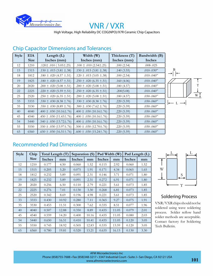
101AFM Microelectronics Inc
Phone (858)755-7688 • Fax (858)348-3217 • 3347 Industrial Court • Suite J • San Diego, CA 92121 USAwww.afmmicroelectronics.com
W
B
L
T
VNR / VXRHigh Voltage, High Reliability DC COG(NPO)/X7R Ceramic Chip Capacitors
Style EIA Size
Length (L)Inches (mm)
Width (W)Inches (mm)
Thickness (T)Inches (mm)
Bandwidth (B)Inches
12 1210 .120± .010 ( 3.05±.25) .100 ± .010 (2.54±.25) .100 (2.54) .008-.02515 1515 .150 ± .015 (3.81 ±.38) .150 ± .015 (3.81 ±.38) .140 (3.55) .010-.030”18 1812 .180 ± .020 (4.57 ±.51) .120 ± .015 (3.05 ±.38) .100 (2.54) .010-.040”19 1825 .180 ± .020 (4.57 ±.51) .250 ± .020 (6.35 ±.51) .160 (4.06) .010-.040”20 2020 .200 ± .020 (5.08 ±.51) .200 ± .020 (5.08 ±.51) .180 (4.57) .010-.040”22 2225 .220 ± .020 (5.59 ±.51) .250 ± .020 (6.35 ±.51) .200(5.08) .010-.040”25 2520 .250 ± .020 (6.35 ±.51) .200 ± .020 (5.08 ±.51) .180 (4.57) .030-.060”33 3333 .330 ± .030 (8.38 ±.76) .330 ± .030 (8.38 ±.76) .220 (5.59) .030-.060”35 3530 .350 ± .030 (8.89 ±.76) .300 ± .030 (7.62 ±.76) .220 (5.59) .030-.060”40 4040 .400 ± .030 (10.16±.76) .400 ± .030 (10.16±.76) .220 (5.59) .030-.060”45 4540 .450 ± .030 (11.43±.76) .400 ± .030 (10.16±.76) .220 (5.59) .030-.060”54 5440 .540 ± .030 (13.72±.76) .400 ± .030 (10.16±.76) .220 (5.59) .030-.060”55 5550 .550 ± .030 (13.97±.76) .500 ± .030 (12.70±.76) .220 (5.59) .030-.060”65 6560 .650 ± .030 (16.51±.76) .600 ± .030 (15.24±.76) .220 (5.59) .030-.060”
Style Chip Size
Total Length (T) Separation (S) Pad Width (W) Pad Length (L)Inches mm Inches mm Inches mm Inches mm
12 1210 0.177 4.50 0.060 1.52 0.115 2.92 0.060 1.5215 1515 0.205 5.20 0.075 1.91 0.171 4.34 0.065 1.6518 1812 0.232 5.89 0.091 2.31 0.146 3.71 0.071 1.8019 1825 0.232 5.89 0.091 2.31 0.272 6.91 0.071 1.8020 2020 0.256 6.50 0.110 2.79 0.221 5.61 0.073 1.8522 2225 0.276 7.01 0.130 3.30 0.268 6.81 0.073 1.8525 2520 0.342 8.69 0.196 4.98 0.221 5.61 0.073 1.8533 3333 0.430 10.92 0.280 7.11 0.365 9.27 0.075 1.9135 3530 0.453 11.51 0.300 7.62 0.335 8.51 0.077 1.9640 4040 0.507 12.88 0.350 8.89 0.435 11.05 0.079 2.0145 4540 0.559 14.20 0.400 10.16 0.435 11.05 0.080 2.0354 5440 0.650 16.51 0.410 10.41 0.435 11.05 0.120 3.0555 5550 0.745 18.92 0.505 12.83 0.535 13.59 0.120 3.0565 6560 0.780 19.81 0.520 13.21 0.635 16.13 0.130 3.30
T
L L
SW
VNR/VXR chips should not be soldered using wave soldering process. Solder reflow hand solder methods are acceptable. Contact factory for Soldering Tech Bulletin.
Soldering Process
Chip Capacitor Dimensions and Tolerances
Recommended Pad Dimensions

102AFM Microelectronics Inc
Phone (858)755-7688 • Fax (858)348-3217 • 3347 Industrial Court • Suite J • San Diego, CA 92121 USAwww.afmmicroelectronics.com
Style EIA Size
500 Vdc 1000 Vdc 2000 Vdc 3000 Vdc 4000 Vdc 5000 VdcMin. Max. Min. Max. Min. Max. Min. Max. Min. Max. Min. Max.
12 1210 10pF 2200pF 10pF 820pF 10pF 270pF
15 1515 27pF 4700pF 27pF 1500pF 12pF 680pF 12pF 150pF 10pF 100pF
18 1812 27pF 2700pF 27pF 1200pF 12pF 470pF 12pF 120pF 10pF 100pF
19 1825 39pF 8200pF 39pF 3900pF 22pF 820pF 22pF 560pF 22pF 390pF
20 2020 39pF 8200pF 39pF 3900pF 22pF 820pF 22pF 560pF 22pF 390pF
22 2225 47pF .012µF 47pF 8200pF 27pF 1200pF 27pF 680pF 27pF 470pF
25 2050 47pF .010µF 47pF 6800pF 27pF 1200pF 27pF 680pF 27pF 470pF
33 3333 120pF .015µF 120pF .012µF 47pF 2700pF 47pF 1200pF 27pF 680pF
35 3530 120pF .022µF 120pF .018µF 47pF 3300pF 47pF 1500pF 27pF 680pF
40 4040 220pF .039µF 220pF .022µF 100pF 5600pF 100pF 2200pF 18pF 1200pF
45 4540 220pF .056µF 220pF .033µF 100pF 6800pF 100pF 3900pF 18pF 1500pF 18pF 1000pF
54 5440 390pF .082µF 390pF .033µF 150pF 8200pF 150pF 3300pF 27pF 2200pF 22pF 1500pF
55 5550 390pF .068µF 390pF .047µF 150pF .010µF 150pF 6800pF 27pF 2200pF 27pF 2200pF
65 6560 470pF .100µF 470pF .068µF 270pF .022µF 270pF 6800pF 47pF 3900pF 47pF 2700pF
C0G (NP0) Dielectric Capacitance Ranges*
Capacitance Range 10pF to .100µFCapacitance Tolerances F±1%, G±2%, J±5%, K±10%, M±20%Dissipation Factor 0.15% Max (25°C, 1 KHz) 1Vrms ±0.2VTemperature Range -55°C to +125°CTemperature Coefficient 0±30ppm/°CInsulation Resistance 1000 V or Rated V at 25°C(Whichever is less) 100GΩ min or 1000MΩµF Whichever is Less
Insulation Resistance 1000 V or Rated V at 125°C(Whichever is less) 10GΩ min or 100MΩµF Whichever is Less
Voltage Range 500V to 5kV (See Table)Dielectric Withstand 1.2 x Rated Voltage 5 Second MinAging None
Chips are supplied unmarked. Marking, if required is an additional charge. Styles 12-15 will be laser marked with EIA capacitance code, and tolerance (821K). Styles 18 and up will be marked with an insulating ink and will contain AFM, capacitance code, tolerance code and lot code.
Marking
PackagingBulk packaging in plastic bags is standard. Please contact factory for optional waffle packaging or tape and reel.
Dielectric Characteristics COG (NPO)
*For Extended Capacitance Values Please Contact Our Factory
VNRHigh Voltage, High Reliability DC COG(NPO) Ceramic Chip Capacitors

103AFM Microelectronics Inc
Phone (858)755-7688 • Fax (858)348-3217 • 3347 Industrial Court • Suite J • San Diego, CA 92121 USAwww.afmmicroelectronics.com
VXRHigh Voltage, High Reliability DC X7R Ceramic Chip Capacitors
Style EIA Size
500 Vdc 1000 Vdc 2000 Vdc 3000 Vdc 4000 Vdc 5000 VdcMin. Max. Min. Max. Min. Max. Min. Max. Min. Max. Min. Max.
12 1210 270pF .033µF
15 1515 680pF .068µF 680pF .022µF
18 1812 680pF .056µF 680pF .018µF 270pF 2500pF
19 1825 1200pF .180µF 1200pF .047µF 560pF 8200pF 560pF 2700pF
20 2020 1200pF .180µF 1200pF .068µF 560pF 8200pF 560pF 3900pF
22 2225 1200pF .220µF 1200pF .082µF 680pF .018µF 680pF 5600pF
25 2520 1200pF .220µF 1200pF .068µF 680pF .015µF 680pF 4700pF
33 3333 3300pF .470µF 3300pF .250µF 1200pF .027µF 1200pF .012µF
35 3530 3300pF .560µF 3300pF .270µF 1200pF .033µF 1200pF .015µF 270pF 6800pF
40 4040 6800pF .860µF 6800pF .390µF 2700pF .047µF 2700pF .018µF 470pF 8600pF
45 4540 6800pF 1.20µF 6800pF .470µF 2700pF .068µF 2700pF .033µF 470pF .010µF 470pF 6800pF
54 5440 .010µF 1.50µF .010µF .680µF 3900pF .056µF 3900pF .012µF 680pF .010µF
55 5550 .010µF 1.80µF .010µF .820µF 3900pF .120µF 3900pF .039µF 680pF .015µF 680pF .010µF
65 6560 .015µF 2.50µF .015µF 1.00µF 6800pF .180µF 6800pF .082µF 1200pF .027µF 1200pF .015µF
X7R Dielectric Capacitance Ranges*
Capacitance Range 270pF to 2.5µFCapacitance Tolerances J±5%, K±10%, M±20%Dissipation Factor 2.5% Max (25°C, 1 KHz) 1Vrms ±0.2VTemperature Range -55°C to +125°CTemperature Coefficient ±15%Insulation Resistance 1000 V or Rated V at 25°C(Whichever is less)
100GΩ min or 1000MΩµF Whichever is Less
Insulation Resistance 1000 V or Rated V at 125°C(Whichever is less)
10GΩ min or 100MΩµF Whichever is Less
Voltage Range 500V to 5kV (See Table)Dielectric Withstand 1.2 x Rated Voltage 5 Second MinAging None
Chips are supplied unmarked. Marking, if required is an additional charge. Styles 12-15 will be laser marked with EIA capacitance code, and tolerance (821K). Styles 18 and up will be marked with an insulating ink and will contain AFM, capacitance code, tolerance code and lot code.
Bulk packaging in plastic bags is standard. Please contact factory for optional waffle packaging or tape and reel.
Marking
Packaging
Dielectric Characteristics X7R
*For Extended Capacitance Values Please Contact Our Factory

104AFM Microelectronics Inc
Phone (858)755-7688 • Fax (858)348-3217 • 3347 Industrial Court • Suite J • San Diego, CA 92121 USAwww.afmmicroelectronics.com
VNCHigh Voltage COG (NPO) Radial Leaded Multilayer Ceramic Capacitors
• Capacitance Range: 10pF to .33µF
• Operating Temperature Range: -55°C to 125°C
• Voltage Range: 500V to 10kV
• Intermediate and Higher Voltages are Available
• High Reliability Long Life
• Conformal CoatedVNC series is high voltage radial lead multilayer ceramic capacitors for use in high
reliability commercial and industrial applications. These capacitors are designed
using a high density, extremely stable ceramic, having temperature coefficients meeting COG (NPO) standards. These
capacitors conform to or exceed design guidelines outlined in DSCC and other MIL drawings and standards. Each
capacitor is 100% tested physically and electrically. Group A and Group B Inspections, as well as partial discharge,
SLAM and CSAM are available as options.
V S15CN LF101 BM
Product Series:V: High Voltage
Dielectrics:N: NPO
Product Type:C: Commercial
Conformal Coated
Size:(See Table)
Termination Code:S: CCFE - Pb/Sn Plated
Capacitance Code:1st two digits are significant: Third digit denotes number of zero(s); R=Decimal point 2R0=2.0pF101=100pF
Tolerance:F: ±1%G: ±2%J: ±5%
K: ±10%M: ±20%
Voltage:J: 500 VdcL: 1000 VdcO :2000 VdcQ: 3000 VdcS: 4000 VdcT: 5000 VdcW: 10000Vdc
Marking:M: Marked
Packaging:B: Bulk
W: Waffle Pack
AFM Part Number CodeC
Test Code:C: Commercial Tests
S: Optional TestsM: Mil-Spec Testing
Typical applications include high voltage power supplies, voltage multipliers, surge protection and other custom applications.
Features
Aplications
272K5kV
AFMDate Code
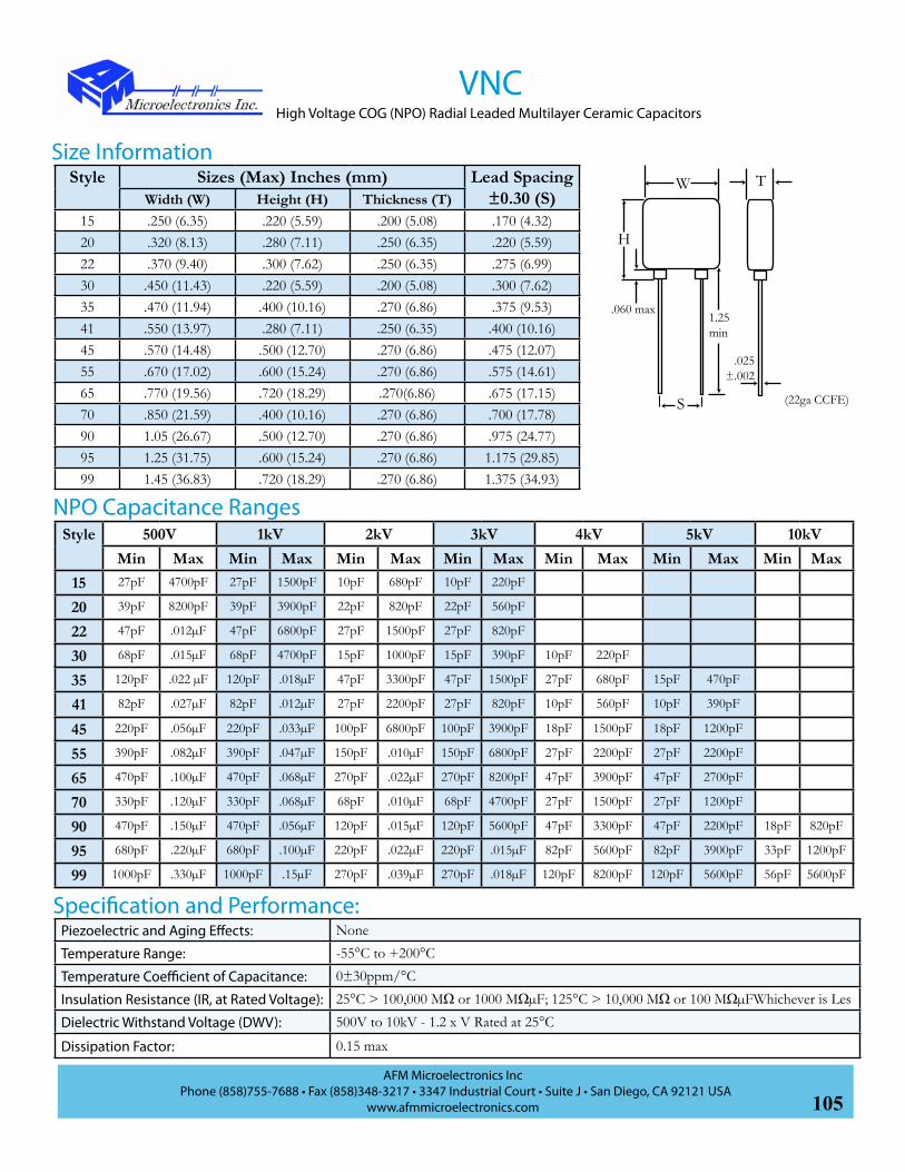
105AFM Microelectronics Inc
Phone (858)755-7688 • Fax (858)348-3217 • 3347 Industrial Court • Suite J • San Diego, CA 92121 USAwww.afmmicroelectronics.com
Style Sizes (Max) Inches (mm) Lead Spacing ±0.30 (S)Width (W) Height (H) Thickness (T)
15 .250 (6.35) .220 (5.59) .200 (5.08) .170 (4.32)20 .320 (8.13) .280 (7.11) .250 (6.35) .220 (5.59)22 .370 (9.40) .300 (7.62) .250 (6.35) .275 (6.99)30 .450 (11.43) .220 (5.59) .200 (5.08) .300 (7.62)35 .470 (11.94) .400 (10.16) .270 (6.86) .375 (9.53)41 .550 (13.97) .280 (7.11) .250 (6.35) .400 (10.16)45 .570 (14.48) .500 (12.70) .270 (6.86) .475 (12.07)55 .670 (17.02) .600 (15.24) .270 (6.86) .575 (14.61)65 .770 (19.56) .720 (18.29) .270(6.86) .675 (17.15)70 .850 (21.59) .400 (10.16) .270 (6.86) .700 (17.78)90 1.05 (26.67) .500 (12.70) .270 (6.86) .975 (24.77)95 1.25 (31.75) .600 (15.24) .270 (6.86) 1.175 (29.85)99 1.45 (36.83) .720 (18.29) .270 (6.86) 1.375 (34.93)
Size Information
Style 500V 1kV 2kV 3kV 4kV 5kV 10kVMin Max Min Max Min Max Min Max Min Max Min Max Min Max
15 27pF 4700pF 27pF 1500pF 10pF 680pF 10pF 220pF
20 39pF 8200pF 39pF 3900pF 22pF 820pF 22pF 560pF
22 47pF .012µF 47pF 6800pF 27pF 1500pF 27pF 820pF
30 68pF .015µF 68pF 4700pF 15pF 1000pF 15pF 390pF 10pF 220pF
35 120pF .022 µF 120pF .018µF 47pF 3300pF 47pF 1500pF 27pF 680pF 15pF 470pF
41 82pF .027µF 82pF .012µF 27pF 2200pF 27pF 820pF 10pF 560pF 10pF 390pF
45 220pF .056µF 220pF .033µF 100pF 6800pF 100pF 3900pF 18pF 1500pF 18pF 1200pF
55 390pF .082µF 390pF .047µF 150pF .010µF 150pF 6800pF 27pF 2200pF 27pF 2200pF
65 470pF .100µF 470pF .068µF 270pF .022µF 270pF 8200pF 47pF 3900pF 47pF 2700pF
70 330pF .120µF 330pF .068µF 68pF .010µF 68pF 4700pF 27pF 1500pF 27pF 1200pF
90 470pF .150µF 470pF .056µF 120pF .015µF 120pF 5600pF 47pF 3300pF 47pF 2200pF 18pF 820pF
95 680pF .220µF 680pF .100µF 220pF .022µF 220pF .015µF 82pF 5600pF 82pF 3900pF 33pF 1200pF
99 1000pF .330µF 1000pF .15µF 270pF .039µF 270pF .018µF 120pF 8200pF 120pF 5600pF 56pF 5600pF
NPO Capacitance Ranges
W T
H
1.25min
.025±.002
S
.060 max
(22ga CCFE)
VNCHigh Voltage COG (NPO) Radial Leaded Multilayer Ceramic Capacitors
Specification and Performance:Piezoelectric and Aging Effects: None
Temperature Range: -55°C to +200°C
Temperature Coefficient of Capacitance: 0±30ppm/°C
Insulation Resistance (IR, at Rated Voltage): 25°C > 100,000 MΩ or 1000 MΩµF; 125°C > 10,000 MΩ or 100 MΩµFWhichever is Les
Dielectric Withstand Voltage (DWV): 500V to 10kV - 1.2 x V Rated at 25°C
Dissipation Factor: 0.15 max

106AFM Microelectronics Inc
Phone (858)755-7688 • Fax (858)348-3217 • 3347 Industrial Court • Suite J • San Diego, CA 92121 USAwww.afmmicroelectronics.com
VXCHigh Voltage X7R Radial Leaded Multilayer Ceramic Capacitors
• Capacitance Range: 100pF to 5.6µF
• Operating Temperature Range: -55°C to 125°C
• Voltage Range: 1kV to 10kV
• Intermediate and Higher Voltages are Available
• High Reliability Long Life
• Conformal Coated
V S15CX LJ101 BM
Product Series:V: High Voltage
Dielectrics:X: X7R
Product Type:C: Commercial
Conformal Coat
Size:(See Table)
Termination Code:S: CCFE - Pb/Sn Plated
Capacitance Code:1st two digits are significant: Third digit denotes number of zero(s); R=Decimal point 2R0=2.0pF101=100pF
Tolerance:J: ±5%
K: ±10%M: ±20%
Voltage:L: 1000 VdcO: 2000 VdcQ: 3000 VdcS: 4000 VdcT: 5000 VdcW: 10000Vdc
Marking:M: Marked
Packaging:B: Bulk
W: Waffle Pack
AFM Part Number CodeC
Test Code:C: Commercial Tests
S: Optional TestsM: Mil-Spec Testing
VXC series is high voltage radial lead multilayer ceramic capacitors for use in high
reliability commercial and industrial applications. These capacitors are designed
using a high density barium titanate ceramic, having temperature coefficients meeting X7R standards. These capacitors
conform to or exceed design guidelines outlined in DSCC and other MIL drawings and standards. Each capacitor is
100% tested physically and electrically. Group A and Group B Inspections, as well as partial discharge, SLAM and
CSAM are available as options.
Typical applications include high voltage power supplies, voltage multipliers, surge protection and other
custom applications.
Features
Aplication
225K1kV
AFMDate Code

107AFM Microelectronics Inc
Phone (858)755-7688 • Fax (858)348-3217 • 3347 Industrial Court • Suite J • San Diego, CA 92121 USAwww.afmmicroelectronics.com
VXCHigh Voltage X7R Radial Leaded Multilayer Ceramic Capacitors
X7R Capacitance RangeStyle 500V 1kV 2kV 3kV 4kV 5kV 10kV
Min Max Min Max Min Max Min Max Min Max Min Max Min Max15 680pF .082µF 680pF .022µF 270pF 3900pF 100pF 1200pF
20 1200pF .180µF 1200pF .068µF 560pF .012µF 560pF 3900pF
22 1200pF .220µF 1200pF .082µF 680pF .018µF 680pF 5600pF
30 1800pF .220µF 1800pF .056µF 390pF 8200pF 390pF 2200pF 150pF 1200pF
35 3300pF .560µF 3300pF .270µF 1200pF .033µF 1200pF .015µF 270pF 6800pF
41 2700pF .390µF 2700pF .150µF 680pF .022µF 680pF 8200pF 270pF 4700pF 270pF 2700pF
45 6800pF 1.20µF 6800pF .470µF 2700pF .068µF 2700pF .033µF 470pF .010µF 470pF 6800pF
55 .010µF 1.80µF .010µF .680µF 3900pF .100µF 3900pF .039µF 680pF .015µF 680pF .010µF
65 .015µF 2.50µF .015µF 1.00µF 6800pF .180µF 6800pF .082µF 1200pF .027µF 1000pF .015µF 270pF 1200pF
70 .010µF 1.50µF .010µF .680µF 1800pF .082µF 1800pF .027µF 680pF .012µF 680pF 8200pF 150pF 1000pF
90 .012µF 2.20µF .012µF 1.00µF 3300pF .150µF 3300pF .056µF 1200pF .027µF 1000pF .022µF 470pF 3900pF
95 .018µF 3.90µF .018µF 1.5µF 5600pF .250µF 5600pF .082µF 2200pF .047µF 2000pF .027µF 820pF 5600pF
99 .027µF 5.60µF .027µF 2.20µF 8200pF .390µF 8200pF .120µF 3300pF .068µF 3000pF .039µF 1000pF .010µF
Style Sizes (Max) Inches (mm) Lead Spacing ±0.30 (S)Width (W) Height (H) Thickness (T)
15 .250 (6.35) .220 (5.59) .200 (5.08) .170 (4.32)20 .320 (8.13) .280 (7.11) .250 (6.35) .220 (5.59)22 .370 (9.40) .300 (7.62) .250 (6.35) .275 (6.99)30 .450 (11.43) .220 (5.59) .200 (5.08) .300 (7.62)35 .470 (11.94) .400 (10.16) .270 (6.86) .375 (9.53)41 .550 (13.97) .280 (7.11) .250 (6.35) .400 (10.16)45 .570 (14.48) .500 (12.70) .270 (6.86) .475 (12.07)55 .670 (17.02) .600 (15.24) .270 (6.86) .575 (14.61)65 .770 (19.56) .720 (18.29) .270(6.86) .675 (17.15)70 .850 (21.59) .400 (10.16) .270 (6.86) .700 (17.78)90 1.05 (26.27) .500 (12.70) .270 (6.86) .975 (24.77)95 1.25 (31.75) .600 (15.24) .270 (6.86) 1.175 (29.85)99 1.45 (36.83) .720 (18.29) .270 (6.86) 1.375 (34.93)
Size InformationW T
H
1.25min
.025±.002
S
.060 max
(22ga CCFE)
Specification and PerformancePiezoelectric and Aging Effects: None
Temperature Range: -55°C to +200°C
Temperature Coefficient of Capacitance: ±15%
Insulation Resistance (IR, at Rated Voltage): 25°C > 100,000 MΩ or 1000 MΩµF; 125°C > 10,000 MΩ or 100 MΩµF Whichever is less
Dielectric Withstand Voltage (DWV): 500V to 10kV - 1.2 x V Rated at 25°C
Dissipation Factor: 2.5% max

108AFM Microelectronics Inc
Phone (858)755-7688 • Fax (858)348-3217 • 3347 Industrial Court • Suite J • San Diego, CA 92121 USAwww.afmmicroelectronics.com
VNM/VRM/VZM
• Capacitance Range: 10pF to .47µF
• Operating Temperature Range: -55°C to 125°C
• Voltage Range: 600V to 5kV
• High Reliability Long Life
• Conformal Coated
• Sizes and Values Conform to MIL-PRF-49467VNM/VRM/VZM series is high voltage radial lead multilayer ceramic capacitors
for use in high reliability commercial, industrial and military applications. These
capacitors are designed in accordance with MIL-PRF-49467 and can be supplied to BP, BR, and BZ voltage temperature
limits. Each capacitor is 100% tested physically and electrically to Group A Inspection, Subgroups 1, 3, 4, as defined
in MIL-PRF-49467. AFM has in-house partial discharge (corona) testing capability and this test is available as an
option. Group B Inspection is also available as an option.
V SAMN LJ101 BM
Product Series:V: High Voltage
Dielectrics:N: NPO - BPR: X7R- BRZ: X7R - BZ
Product Type:M: Mil SpecApplicable
Size:(See Table)
Capacitance Code:1st two digits are significant: Third digit denotes number of zero(s); 101=100pF
Tolerance:J: ±5%K: ±10%M: ±20%
Voltage:K: 600 VdcL: 1000 VdcO: 2000 VdcQ: 3000 VdcS: 4000 VdcT: 5000 Vdc
Marking:M: Marked
(per MIL-PRF-49467)*
Packaging:B: Bulk
W: Waffle Pack
AFM Part Number CodeM
Test Code:S: Optional Tests
M: Group A MIL PRF-49467
High Voltage Radial Leaded Multilayer Ceramic Capacitors MIL-PRF-49467 (Equivalent)
Termination Code:S: CCFE - Pb/Sn Plated
Features
Specification and PerformanceBP, BR and BZ Temperature Coefficient: See “Voltage - Temperature Limits” table on next page
Insulation Resistance (IR, at Rated Voltage):
25°C > 100,000 MΩor 1000 MΩµF125°C > 10,000 MΩor 100 MΩµFWhichever is Less
Dissipation Factor:0.15% max for BP2.5% max for BR and BZ

109AFM Microelectronics Inc
Phone (858)755-7688 • Fax (858)348-3217 • 3347 Industrial Court • Suite J • San Diego, CA 92121 USAwww.afmmicroelectronics.com
VNMHigh Voltage Radial Leaded Multilayer Ceramic Capacitors MIL-PRF-49467 (Equivalent)
Style Sizes (Max) Inches (mm) Lead Spacing ±0.30 (S)Width (W) Height (H) Thickness (T)
A .250 (6.35) .220 (5.59) .200 (5.08) .170 (4.32)
B .320 (8.13) .280 (7.11) .250 (6.35) .220 (5.59)
C .370 (9.40) .300 (7.62) .250 (6.35) .275 (6.99)
D .470 (11.94) .400 (10.16) .270 (6.86) .375 (9.53)
E .570 (14.48) .500 (12.70) .270 (6.86) .475 (12.07)
F .670 (17.02) .600 (15.24) .270 (6.86) .575 (14.61)
G .770 (19.56) .720 (18.29) .270 (6.86) .675 (17.15)
Extended Case CodesJ 1.25 (31.75) .600 (15.24) .270(6.86) 1.10 (27.94)
K 1.45 (36.83) .720 (18.29) .270 (6.86) 1.30 (33.02)
L .450 (11.43) .220 (5.59) .200 (5.08) .300 (7.62)
M .450 (11.43) .220 (5.59) .270 (6.86) .300 (7.62)
Size Information
Style 600V 1kV 2kV 3kV 4kV 5kVMin Max Min Max Min Max Min Max Min Max Min Max
A 10pF 5600pF 10pF 1000pF 10pF 330pF
B 10pF 5600pF 56pF 1800pF 22pF 820pF 10pF 560pF
C 6800pF .012µF 68pF 2700pF 27pF 1200pF 22pF 680pF
D .018µF .039µF 120pF 4700pF 47pF 2200pF 39pF 1500pF 18pF 1000pF
E .047µF .068µF 270pF .018 µF 100pF 4700pF 100pF 3300pF 100pF 1800pF 100pF 1000pF
F 390pF .018µF 150pF 6800pF 150pF 5600pF 150pF 3300pF 150pF 1800pF
G 470pF .027µF 270pF .010µF 270pF 6800pF 270pF 4700pF 270pF 3300pF
K 560pF 3900pF
L 10pF 82pF
M 47pF 820pF
BP COG (NPO) Dielectric Capacitance Ranges
Voltage - Temperature Limits(-55°C to +125°C)
TC No Load Rated Voltage
% Change
BP 0±30ppm/°C 100% 0±30ppm/°C
BR ±15% 100% +15, -40%
BZ ±15% 60% +15, -45%
W T
H
1.25min
.025±.002
S
.060 max
(22ga CCFE)

110AFM Microelectronics Inc
Phone (858)755-7688 • Fax (858)348-3217 • 3347 Industrial Court • Suite J • San Diego, CA 92121 USAwww.afmmicroelectronics.com
VRM/VZMHigh Voltage Radial Leaded Multilayer Ceramic Capacitors MIL-PRF-49467 (Equivalent)
Style 600V 1kV 2kV 3kV 4kV 5kVMin Max Min Max Min Max Min Max Min Max Min Max
A 100pF .027µF 470pF 4700pF 220pF 1500pF
B .033µF .082µF 1200pF .010µF 390pF 3900pF 270pF 1500pF
C .100µF 1500pF .027µF 820pF 5600pF 560pF 2200pF
D .12µF .270µF 3300pF .068µF 1200pF .015µF 1000pF 6800pF 100pF 4700pF
E .330µF .470µF 6800pF .150µF 2700pF .033µF 2700pF .012µF 470pF 6800pF 390pF 2200pF
F .100µF .270µF 3900pF .047µF 3300pF .022µF 680pF .010µF 560pF 5600pF
G .12µF .470µF 6800pF .100µF 5600pF .039µF 1200pF .018µF 1200pF 8200pF
J 6800pF .047µF. 1800pF .027µF 2200pF .015µF
K 8200pF .082µF 2700pF .047µF 3300pF .022µF
M 100pF 820pF 100pF 560pF
BR (X7R) Dielectric Capacitance Ranges
BZ (X7R) Dielectric Capacitance RangesStyle 1kV 2kV 3kV 4kV 5kV
Min Max Min Max Min Max Min Max Min Max
A 680pF .010µF 220pF 2700pF
B 1200pF .015µF 560pF 6800pF 560pF 2200pF
C 1500pF .022µF 680pF .010µF 680pF 3300pF
D 3300pF .056µF 1200pF .027µF 1200pF 8200pF 120pF 6800pF
E 6800pF .120µF 2700pF .056µF 2700pF .018µF 680pF .010µF 470pF 6800pF
F .100µF .180µF 3900pF .082µF 3900pF .027µF 820pF .015µF 560pF .010µF
G 5600pF .150µF 6800pF .047µF 1200µF .027µF 1200pF .015µF
J 6800pF .047µF. 2200pF .039µF 2200pF .022µF
K 3300pF .056µF 3300pF .033µF

111AFM Microelectronics Inc
Phone (858)755-7688 • Fax (858)348-3217 • 3347 Industrial Court • Suite J • San Diego, CA 92121 USAwww.afmmicroelectronics.com
GBBL Substrate has 10 times and 20 times higher dielectric constant than traditional material but keeps
the same property; Low-loss; Low insertion loss; Operates at very much higher frequency than traditional
material and below the self-resonant frequency.
ApplicationDC Block, RF Bypass, Source Bypass, and Impedance Matching.
SpecificationK Size Thickness D.F. (%) I.R. (25~50V) TCC(-55°~ +125°C)
20000-22000 1.5”x1.5” 0.005”-0.020” <1.5 >10G X7R <+/-15%
25000=Avx MAXI + (<25mil part with border K=30000~50000)
1.5”x1.5” 0.005”-0.020” <1.5 >10G X7R <+/-15%
Low TC 15000-25000
1.5”x1.5” 0.005”-0.020” <1.5 >10G <+/-4.0%
Super High K 45000-50000 (<25mil Part With border K=90000-100000)
1.5”x1.5” 0.005”-0.020” <1.5 >10G X7S<+/-18~20%
GBBL SUBSTRATE Substrate for Single Layer (Grain Boundary Barrier Layer) Capacitors.
Features

112AFM Microelectronics Inc
Phone (858)755-7688 • Fax (858)348-3217 • 3347 Industrial Court • Suite J • San Diego, CA 92121 USAwww.afmmicroelectronics.com
AFM supplies the Ultra Low Fired ceramic powder for Multilayer Ceramic Capacitor
(MLCC) and Single Layer Capacitor (SLC). The powder system includes COG and X7R
formulation. Other formulation such as Z5U and Y5V are developing. All formulations are
fired at lower than 9200C. Therefore, the inner electrode can be used 95 Ag/5 Pd or 100%
Silver, which will dramatically, reduces the cost of MLCC.
All formulations are Lead(Pb), Cadmium(Cd), and Bismuth(Bi) free. The COG ceramic
powder is for microwave application that has high Q, low ESR, at high frequency. This
feature allows the MLCC can be used in cellular phone, communication device, microwave
amplifier, Blue Tooth module, computer etc.
X7R formulation has very fine grain size and density structure. This feature allows the
manufacture to make thinner ceramic sheets.
Dielectric Powder

113AFM Microelectronics Inc
Phone (858)755-7688 • Fax (858)348-3217 • 3347 Industrial Court • Suite J • San Diego, CA 92121 USAwww.afmmicroelectronics.com
200C-ULF Powder (K20 Ultra-Low-Fire COG Dielectric)
Features1. MgTiO3 based ultra-low-fire COG dielectric
2. Dielectric Constant of 20-23
3. Excellent insulation resistance
4. High Q at high frequency
5. No Cd, Pb, Bi containing compounds
Typical Physical Properties1. Particle Size (D50) 0.8-1.2um
2. Surface Area 2.0-4.0 m2/g
3. Specific Gravity 3.3-3.8g/cc
4. +325 mesh <0.5%
Typical Fired Electrical Properties1. Dielectric Constant 20-23
2. Dissipation Factor(1MHz,1.0Vrms) 0.020%
Q(0402 14pf) @(1 GHz) 137
ESR 096 Ohm
3. TCC 0± 30ppm/oC from -55-125oC
4. IR at 25oC >5,000 Ohm-F
125oC >1,000 Ohm-F
5. Dielectric Withstanding Voltage >1000V/mil
Sample size available
Processing Guidelines(Detailed instructions available)
1. 200C-ULF is a fine particle size, deagglomerated
powder. No further particle size reduction is required.
2. ZrO2 media is recommended for mixing/milling
operations. Contaminants such as aluminum oxides
will result in degradation of electrical properties.
3. 50wt% ceramic /50% binder ratio is recommended
as a starting point for casting using PVB or B7 acrylic
binder systems.
4. Firing on ZrO2 setters is recommended.
5.Firing temperature is in the 880-920oC range
with a 2 hours soaking at peak temperature.
Compatible Materials systems1.200C-ULF is compatible with solvent base binder
system.
2. 200C-ULF is compatible with commercially
available 95%Ag/5%Pd or 100%Ag electrode system.

114AFM Microelectronics Inc
Phone (858)755-7688 • Fax (858)348-3217 • 3347 Industrial Court • Suite J • San Diego, CA 92121 USAwww.afmmicroelectronics.com
252X-ULF Powder(K2500 Ultra-Low-Fire X7R Dielectric)
Features1. BaTiO3 based ultra-low-fire X7R dielectric
2. Dielectric Constant of 2300-2700
3. Excellent insulation resistance
4. Resistant to physical defects
5. No Cd, Pb, Bi containing compounds
Typical Physical Properties1. Particle Size (D50) 0.8-1.2um
2. Surface Area 2.0-4.0 m2/g
3. Specific Gravity 5.3-5.7g/cc
4. +325 mesh <0.5%
Typical Fired Electrical Properties1. Dielectric Constant 2300-2700
2. Dissipation Factor(1MHz,1.0Vrms) 1.700%
3. TCC 15% (-55-125oC)
4. IR at 25oC >20,000 Ohm-F
125oC >2,000 Ohm-F
5. Dielectric Withstanding Voltage >600V/mil
Sample size available
Processing Guidelines(Detailed instructions available)
1. 252X-ULF is a fine particle size, deagglomerated
powder. No further particle size reduction is required.
2. ZrO2 media is recommended for mixing/milling
operations. Contaminants such as aluminum oxides
will result in degradation of electrical properties.
3. 60wt% ceramic /40% binder ratio is recommended
as a starting point for casting using PVB or B7 acrylic
binder systems.
4. Firing on stainless steel or superalloy boat (which
reduces the recurring cost of setters) is recommended.
5.Firing temperature is in the 850-900oC range with a 2
hours soaking at peak temperature.
Compatible Materials systems1.252X-ULF is compatible with solvent base binder
system.
2. 252X-ULF is compatible with commercially
available 95%Ag/5%Pd or 100%Ag electrode system.

115AFM Microelectronics Inc
Phone (858)755-7688 • Fax (858)348-3217 • 3347 Industrial Court • Suite J • San Diego, CA 92121 USAwww.afmmicroelectronics.com
Cross ReferenceC
ross
Ref
eren
ce G
uide
to E
quiv
alen
t Par
t Num
bers
AFM
AT
CA
VX
DL
IT
EM
EX
MIL
-C-5
5681
Exam
ple
MPR
12T1
00JC
MT
ATC
100B
100J
T501
XT
AQ
147M
100J
ATM
EC
17A
H10
0J4Z
NX
1T50
1CH
B10
0JC
LE
Tin
Pla
ted
Ove
r N
icke
l Bar
rier
RoH
SC
ompl
iant
MPR
11T
MN
R11
TA
TC10
0A…
TA
TC70
0A…
TA
Q12
EM…
TA
Q12
EA…
TC
11A
H…
ZC
11C
F…Z
CH
A…
SSH
A…
SM
PR12
TM
NR
12T
ATC
100B
…T
ATC
700B
…T
AQ
147M
…T
AQ
147A
…T
C17
AH
…Z
C17
CF…
ZC
HB
…S
SHB
…S
MPH
25T
MN
H25
TA
TC10
0C…
TA
TC70
0C…
TH
QC
C…
TC
22A
H…
ZC
22C
F…Z
CPX
…S
CLX
…S
MPH
U1T
MN
HU
1TA
TC10
0E…
TA
TC70
0E…
TH
QC
E…T
C40
AH
…Z
C40
CF…
ZC
PE…
SC
LE…
S
Tin
Pla
ted
Ove
r C
oppe
r Bar
rier
RoH
SC
ompl
iant
Non
-M
agne
tic
MPR
11N
MN
R11
NA
TC10
0A…
TNA
TC70
0A…
TNC
11A
H…
WC
11C
F…W
CH
A…
CSH
A…
CM
PR12
NM
NR
12N
ATC
100B
…TN
ATC
700B
…TN
C17
AH
…W
C17
CF…
WC
HB
…C
SHB
…C
MPH
25N
MN
H25
NA
TC10
0C…
TNA
TC70
0C…
TNC
22A
H…
WC
22C
F…W
CPX
…C
CLX
…C
MPH
U1N
MN
HU
1NA
TC10
0E…
TNA
TC70
0E…
TNC
40A
H…
WC
40C
F…W
CPE
…C
CLX
…C
Tin
/ Pb
Pla
ted
Ove
r Nic
kel
Bar
rier
MPR
11W
MN
R11
WA
TC10
0A…
WA
TC70
0A…
WA
Q12
EM…
JA
Q12
EA…
JC
11A
H…
UC
11C
F…U
CD
R12
BG
CD
R12
BP
MPR
12W
MN
R12
WA
TC10
0B…
WA
TC70
0B…
WA
Q14
7M…
JA
Q14
7A…
JC
17A
H…
UC
17C
F…U
CD
R14
BG
CD
R14
BP
MPH
25W
MN
H25
WA
TC10
0C…
WA
TC70
0C…
WH
QC
C…
JC
22A
H…
UC
22C
F…U
MPH
U1W
MN
HU
1WA
TC10
0E…
WA
TC70
0E…
WH
QC
E…J
C40
AH
…U
C40
CF…
U
Tin
/ Pb
Pla
ted
Ove
r Nic
kel
Bar
rier W
ith
Hea
vy S
n/P
b S
olde
r Dip
MPR
11P
MN
R11
PA
TC10
0A…
PA
TC70
0A…
PA
Q12
EM…
JA
Q12
EA…
JC
11A
H…
TC
11C
F…T
CD
R12
BG
CD
R12
BP
MPR
12P
MN
R12
PA
TC10
0B…
PA
TC70
0B…
PA
Q14
7M…
JA
Q14
7A…
JC
17A
H…
TC
17C
F…T
CD
R14
BG
CD
R14
BP
MPH
25P
MN
H25
PA
TC10
0C…
PA
TC70
0C…
PH
QC
C…
JC
22A
H…
TC
22C
F…T
MPH
U1P
MN
HU
1PA
TC10
0E…
PA
TC70
0E…
PH
QC
E…J
C40
AH
…T
C40
CF…
T

116AFM Microelectronics Inc
Phone (858)755-7688 • Fax (858)348-3217 • 3347 Industrial Court • Suite J • San Diego, CA 92121 USAwww.afmmicroelectronics.com
Cro
ss R
efer
ence
Gui
de to
Equ
ival
ent P
art N
umbe
rs
AFM
AT
CA
VX
DL
IT
EM
EX
MIL
-C-5
5681
Lead
ed w
ith
Mic
rost
rip/
Non
-mag
netic
MPR
12M
/ M
NM
NR
12M
/ M
NA
TC10
0B…
MS/
MN
ATC
700B
…M
S/M
NC
17A
H…
A/W
AC
17C
F…A
/WA
CH
B…
1SH
B…
1C
DR
21B
GC
DR
21B
P
MPH
25M
/ M
NM
NH
25M
/ M
NA
TC10
0C…
MS/
MN
ATC
700C
…M
S/M
NH
QLC
C22
AH
…A
/WA
C22
CF…
A/W
AC
PX…
1C
LX…
1
MPH
1M/M
NM
NH
1M /
MN
ATC
100E
…M
S/M
NA
TC70
0E…
MS/
MN
HQ
LEC
40A
H…
A/W
AC
40C
F…A
/WA
CPE
…1
CLX
…1
Lead
ed w
ith
Axi
al R
ibbo
n /
Non
-mag
netic
MPR
12B
/ B
NM
NR
12B
/ B
NA
TC10
0B…
AR
/AN
ATC
700B
…A
R/A
NC
17A
H…
C/W
CC
17C
F…C
/WC
CH
B…
2SH
B…
2C
DR
22B
GC
DR
22B
P
MPH
25B
/BN
MN
H25
B /
BN
ATC
100C
…A
R/A
NA
TC70
0C…
AR
/AN
HQ
LCC
22A
H…
C/W
CC
22C
F…C
/WC
CPX
…2
CLX
…2
MPH
1B /
BN
MN
H1B
/ B
NA
TC10
0E…
AR
/AN
ATC
700E
…A
R/A
NH
QLE
C40
AH
…C
/WC
C40
CF…
C/W
CC
PE…
2C
LX…
2
Lead
ed w
ith
Axi
al W
ire /
Non
-mag
netic
MPR
12A
/ A
NM
NR
12A
/ A
NA
TC10
0B…
AW
/BN
ATC
700B
…A
W/B
NC
17A
H…
E/W
EC
17C
F…E/
WE
CH
B…
6SH
B…
6C
DR
25B
GC
DR
25B
P
MPH
25A
/AN
MN
H25
A /
AN
ATC
100C
…A
W/B
NA
TC70
0C…
AW
/BN
C22
AH
…E
/WE
C22
CF…
E/W
EC
PX…
6C
LX…
6
MPH
1A /
AN
MN
H1A
/ A
NA
TC10
0E…
AW
/BN
ATC
700E
…A
W/B
NC
40A
H…
E/W
EC
40C
F…E/
WE
CPE
…6
CLX
…6
Lead
ed w
ith
Rad
ial W
ire /
Non
-mag
netic
MPR
12Q
/ Q
NM
NR
12Q
/ Q
NA
TC10
0B…
RW
/RN
ATC
700B
…R
W/R
NC
17A
H…
F/W
FC
17C
F…F/
WF
CH
B…
7SH
B…
7C
DR
23B
GC
DR
23B
P
MPH
25Q
/QN
MN
H25
Q /
QN
ATC
100C
…R
W/R
NA
TC70
0C…
RW
/RN
C22
AH
…F/
WF
C22
CF…
F/W
FC
PX…
7C
LX…
7
MPH
1Q /
QN
MN
H1Q
/ Q
NA
TC10
0E…
RW
/RN
ATC
700E
…R
W/R
NC
40A
H…
F/W
FC
40C
F…F/
WF
CPE
…7
CLX
…7
Cross Reference

117AFM Microelectronics Inc
Phone (858)755-7688 • Fax (858)348-3217 • 3347 Industrial Court • Suite J • San Diego, CA 92121 USAwww.afmmicroelectronics.com
High Reliability Multilayer Ceramic Capacitor Test Protocols
AFM Microelectronics, Inc. (AFM) performs 100 percent testing of
capacitors for all the dielectric systems offered. As a minimum, all
capacitors are tested by AFM’s Commercial Test Protocol to verify
mechanical and electrical conformance to the applicable AFM or customer
specifications. For high reliability applications enhanced test protocols are
available options. This extended testing is outlined in the “High Reliability
Test Protocol” table. These tests are in addition to the Commercial Tests
and can be performed on the total lot or on a sample selected from the
manufacturing lot.
For extended design verification testing (DVT), AFM offers other
optional Environmental, Mechanical and Electrical Testing. These tests are
performed on samples randomly selected from the production lot. These
tests are used to verify that the design and manufacturing processes are
well suited for the specific application and help verify reliable operation.
These tests are typically destructive in nature and capacitors used for these
tests are not certified for use in the production lot.
AFM follows the test methods and specifications outlined in MIL-
STD-202, EIA-198 and can provide Group A, B and C testing to the MIL-
PRF-49467, MIL-PRF-55681 and MIL-PRF-39014*. AFM also works
with our customers to design custom test protocols that are specific to
the customer’s application. This can include burn-in and life testing up to
at 300°C for capacitors used in oil and geothermal exploration and other
high temperature applications, and high current pulse testing for detonator
application.
*These capacitors are not MIL qualified

118AFM Microelectronics Inc
Phone (858)755-7688 • Fax (858)348-3217 • 3347 Industrial Court • Suite J • San Diego, CA 92121 USAwww.afmmicroelectronics.com
Test Item Conditions Requirements
All Commercial Tests Plus:
Voltage Conditioning:
Capacitors, ≥500V are Burned-in at Rated Voltage at 125° C for 100 Hours
Capacitors, <500V are Burned at 200% Rated Voltage
PDA > 10% Lot is Rejected
Hot Insulation Resistance (IR) Method 302 of MIL-STD-202 See Commercial Protocol
IR=10GΩ or 100MΩ•µF
Percent Defective Allowed (PDA)
Cumulative Failures (PDA) After Voltage Conditioning Shall Not Exceed 10%.
Visual Defect and Out of Tolerance Pieces Not Included in PDA
High ReliabilityTest Protocol
High Reliability Multilayer Ceramic Capacitor Test Protocols
Test Item Conditions Requirements
Destructive Physical Analysis Cross Section Representative Sample Depending on Lot Size
Microscopic Examination to AFM Internal Specification
Capacitance Method 305 MIL-STD-202 100% at 25°C and 1Vrms Per
Dissipation Factor Method 305 MIL-STD-202 100% at 25°C and 1Vrms X7R≤2.5%, NP0≤0.15%
Dielectric Withstand Voltage (DWV) Method 301 MIL-STD 202
250V or Less - 250% of Rated Voltage250V to 400V - 150% of Rated Voltage≥500V to 5kV -120% of Rated Voltage
Insulation Resistance Method 301 MIL-STD 202 Rated Voltage or 1kV Whichever is Less100GΩ or 1000MΩ•µF @ 25°C Whichever is Less
Visual / Mechanical Inspection 100% Per AFM InternalSpecifications Reject Visual Defects
Commercial Test Protocol

119AFM Microelectronics Inc
Phone (858)755-7688 • Fax (858)348-3217 • 3347 Industrial Court • Suite J • San Diego, CA 92121 USAwww.afmmicroelectronics.com
Test Item Conditions Requirements
Thermal Shock Mil-STD-202, Method 107, Condition A (125°C) 20 cycles
No More Than 1 Failure Allowed in the Following
Mechanical and Electrical Tests
Humidity Steady State (Low Voltage)
MIL-STD-202, Method 103, Condition A 85°C, 85% RH, DC voltage 1.3 ± 0.25 Vdc No More Than 1 Failure Allowed
Immersion MIL-STD-202, Method 104 Condition B
Terminal Strength MIL-STD-202, Method 211, Condition A 5lbs Min Force
Resistance toSoldering Heat MIL-STD-202, Method 210, Condition B Conformal Coated or
Encapsulated Capacitors Only
Partial Discharge(Corona) MIL-PRF-49467, Appendix B
C≤5nF ≤5 picocoulombsC>5nf and < .10µF: <15 picocoulombs
C≥.1µF but < .47µF: <50pC AC Applied Voltage is 42% of Rated DC Voltage
Radiographic Inspection MIL-STD-202, Method 209 Dielectric Voids Less Than 1/2Dielectric Thickness
Life Test Rated Voltage, 125°C for 1000 Hours PDA 1 Piece or 10%Whichever is Greater
Solderablity MIL-STD-202 Method 208 > 95% Coverage
Body Insulation 1000 Volt DC Per MIL-PRF-49467 orMIl-PRF-39014 Where Applicable No Breakdown
Optional Environmental, Mechanical and Electrical Testing
Test DataProduction test data is available when requested by customer. High reliability testing and data package charges will
be negotiated at time of order.
Certificates of Compliance (CofC)CofCs can be supplied with all shipments if requested by customer.
High Reliability Multilayer Ceramic Capacitor Test Protocols

120AFM Microelectronics Inc
Phone (858)755-7688 • Fax (858)348-3217 • 3347 Industrial Court • Suite J • San Diego, CA 92121 USAwww.afmmicroelectronics.com
Useful Capacitor Formulas
Capacitance (Farads) English: C = (0.224 K A) / TDMetric: C = (0.0884 K A) / TD
Dissipation FactorD.F. = tan δ (loss angle) = ESR/XC = (2πfC) (ESR)
Equivalent Series Resistance ESR (Ohms)
ESR = (DF) XC = DF/2πfC = Rsd + Rsm Rsd: Dielectric Loss Rsm: Metal Loss
Quality Factor Q = cotan δ = 1/DF
Self Resonant Frequency, S.RF (Hz) S.R.F. = 1/(2π √ (LC))
Capacitive Reactance (Ohms) XC = 1/(2πfC)
Inductive Reactance (H) XL = 2πfL
Linear Charge of a Capacitor I = C (dV/dt)
Total Impedance of a Capacitor (Ohms) Z = √ [RS2 + (XC - XL )
2 ]
Power Loss Power Loss = (2πfCV2) (DF)
Power Factor PF = sin δ (loss angle) - cos Φ (Phase angle)
KVA (Kilowatts) KVA = 2πfCV2 X 10-3
Temperature Coefficient of Capacitance (TCC) T.C. = [(Ct - C25 ) / C25 (Tt - 25)] X 106
Capacitance Drift CD = [(C1 - C2 ) / C1] X 100
Aging Rate A.R. = % ΔC / decade of time
Root Mean Square rms = 0.707 Vp
Capacitors in Series
Any Number1/CT = 1/C1 + 1/C2 + •••. + 1/CnTwo CapacitorsCT = C1 C2 / (C1 + C2 )
Capacitors in Parellel Any NumberCT = C1 + C2 + •••. + Cn
Energy Stored in Capacitor E= ½ CV2
Ceramic Capacitor Reliability L0 / Lt = (Vt / V0 )X (Tt / T0)
Y

121AFM Microelectronics Inc
Phone (858)755-7688 • Fax (858)348-3217 • 3347 Industrial Court • Suite J • San Diego, CA 92121 USAwww.afmmicroelectronics.com
Prefix Numveric Values
Pico 10-12
Nano 10-9
Micro 10-6
Mili 10-3
Deci 10-1
Deca 101
Kilo 103
Mega 106
Giga 109
Tera 1014
A= Area
f= Frequency
K= Dielectric Constant
L= Inductance
L0= Operating Life
Lt= Test Life
RS= Series Resistance
t= Time
T0= Operating Temperature
TD= Dielectric Thickness
Tt= Test Temperature
V= Voltage
V0= Operating Temperature
Vt= Test Voltage
X, Y = Exponent Effect of Voltage and Temperatureδ= Loss angle
SymbolsMetric Prefixes
Metric Prefixes & Symbols

122AFM Microelectronics Inc
Phone (858)755-7688 • Fax (858)348-3217 • 3347 Industrial Court • Suite J • San Diego, CA 92121 USAwww.afmmicroelectronics.com
ESI Auto-Termination
Isostatic Press Auto-Test and Sort
Automated Printer / Stack and Laminate
Equipments

AFM Microelectronics Inc. 3347 Industrial Court Suite JSan Diego, CA 92121 U.S.A.
Phone: (858)755-7688Fax: (858)348-3217
www.afmmicroelectronics.comEmail: [email protected]
ESI Auto-Termination
Isostatic Press Auto-Test and Sort
Automated Printer / Stack and Laminate