Embed Size (px)
Citation preview

Centroid M-Series Mill Operators Manual
CNC Software Version: CNC12 Version 4.14Models: M400 & M39
www.centroidcnc.com
Copyright c©2013-2019 Centroid Corp. Howard, PA 16841
U.S. Patent #6490500

Throughout this manual and on associated products where applicable, in accordance with ANSI Z535, thefollowing symbols and words are used as defined below:
Information provided by CENTROID relating to wiring, installation, and operation of CNC components isintended as only a guide, and in all cases a qualified technician and all applicable local codes and laws mustbe consulted. CENTROID makes no claims about the completeness or accuracy of the informationprovided, as it may apply to an infinite number of field conditions.
As CNC control products from CENTROID can be installed on a wide variety of machine tools NOT soldor supported by CENTROID, you MUST consult and follow all safety instructions provided byyour machine tool manufacturer regarding the safe operation of your machine and uniqueapplication.
CENTROID CNC controls provide facilities for a required Emergency Stop circuit which can be used tocompletely disable your machine tool in the event of an emergency or unsafe condition. Properinstallation of your CNC control MUST include the necessary wiring to disable ALL machinetool movement when the Emergency Stop button is pressed. This includes machine, servo motors,tool changers, coolant pumps, and any other moving parts. DO NOT disable or alter any safety feature ofyour machine or CNC control.
1

Never alter or remove any safety sign or symbol from your machine or CNC controlcomponents. If signs become damaged or worn, or if additional signs are needed to emphasize aparticular safety issue, contact your dealer or CENTROID.
CNC Control Operating SpecificationsMinimum Maximum
Operating Temperature 40◦F (5◦C) 104◦F (40◦C)
Ambient Humidity30% relative, non-condensing
90% relative, non-condensing
Altitude 0 Ft. (Sea Level) 6000 Ft. (1830m)Input Voltage (110, 220, 440 VAC, Sys-tem Dependent)
-10% of Specified SystemInput Voltage
+10% of Specified SystemInput Voltage
Note: Your machine may have operating conditions different than those shown above. Always consultyour machine manual and documentation.
Safety signs and labels found on your machine tool, and on CNC system components typically follow thefollowing examples:
2

CNC Machine Tool Safety• All machine tools contain hazards from rotating parts; movement of belts, pulleys, gears, and chains;
high voltage electricity; compressed air; noise; and airborne dust, chips, swarf, coolant, and lubricants.Basic safety precautions must be followed to reduce the risk of personal injury and property damage.
• Your local safety codes and regulations must be consulted before installation and operation of yourmachine and CENTROID CNC control. Should a safety concern arise, always contact your dealer orservice technician immediately.
• Access to all dangerous areas of the machine must be restricted while the machine is in use. Ensurethat all safety guards and doors are properly in place during use. Automatically controlledmachine tools may start, stop, or move suddenly at any time. Do not enter themachining area when the machine is in motion; death or severe injury may result.
• Personal protective equipment, particularly ANSI-approved impact safety glasses andOSHA-approved hearing protection must be used. Proper handling, storage, use, and disposal ofmaterials in accordance with manufacturer’s instructions and Material Safety Data Sheets (MSDS, oryour local equivalent) must be followed.
• DO NOT operate your machine or CNC control in explosive atmospheres or in environmentalconditions outside of the manufacturer’s specified ranges. Electrical power must meet thespecifications provided by your machine and CNC control manufacturer.
• DO NOT operate your machine or CNC control if any safety systems are damaged or missing.Excessively scratched or damaged windows and guards must be replaced.
• ONLY authorized personnel should be allowed to operate the machine and CNC control. Improperoperation can cause injury, death, and machine or control damage, and may void applicablewarranties.
• All electrical enclosures and panels MUST be closed and secured at all times except duringinstallation and service. Only qualified electricians and service personnel should have access to theselocations. Hazards arising from high voltage electricity and heat exist in the control cabinet, and mayexist even after the main disconnect is turned OFF.
• Improperly clamped or fixtured parts; improperly secured tooling; and broken parts, fixtures, andtooling resulting from machining operations at unsafe feedrates and speeds may result in projectilesbeing ejected from your machine, even through safety systems such as guards and doors. Alwaysfollow safe and reasonable machining practices and follow all safety precautions provided by yourtooling and machine manufacturer.
• Ultimate responsibility for safe operation and maintenance of your machine and CNC control restswith shop owners and machine operators. Before performing any work or maintenance all individualsshould be thoroughly acquainted with the safe operation of BOTH machine tool AND CNC control.
• Shop owners and operators are responsible for ensuring that shop and machine safety systems such asEmergency Stop and fire suppression systems are present and functioning properly, as required bylocal codes and regulations.
3

CNC Control Warning Labels
4

Contents
1 Introduction 101.1 DRO Display . . . . . . . . . . . . . . . . . . . . . . . . . . . . . . . . . . . . . . . . . . . . 101.2 Distance-to-Go DRO . . . . . . . . . . . . . . . . . . . . . . . . . . . . . . . . . . . . . . . . 111.3 Status Window . . . . . . . . . . . . . . . . . . . . . . . . . . . . . . . . . . . . . . . . . . . 111.4 Message Window . . . . . . . . . . . . . . . . . . . . . . . . . . . . . . . . . . . . . . . . . . 111.5 Options Window . . . . . . . . . . . . . . . . . . . . . . . . . . . . . . . . . . . . . . . . . . 111.6 User Window . . . . . . . . . . . . . . . . . . . . . . . . . . . . . . . . . . . . . . . . . . . . 111.7 Conventions . . . . . . . . . . . . . . . . . . . . . . . . . . . . . . . . . . . . . . . . . . . . . 121.8 Machine Home . . . . . . . . . . . . . . . . . . . . . . . . . . . . . . . . . . . . . . . . . . . 131.9 Mill M and G Codes . . . . . . . . . . . . . . . . . . . . . . . . . . . . . . . . . . . . . . . . 151.10 How to unlock software features or unlock your Control . . . . . . . . . . . . . . . . . . . . 161.11 Skinning . . . . . . . . . . . . . . . . . . . . . . . . . . . . . . . . . . . . . . . . . . . . . . . 16
2 Operator Panel 172.1 Axis Jog Buttons . . . . . . . . . . . . . . . . . . . . . . . . . . . . . . . . . . . . . . . . . . 172.2 Slow/Fast . . . . . . . . . . . . . . . . . . . . . . . . . . . . . . . . . . . . . . . . . . . . . . 172.3 Inc/Cont . . . . . . . . . . . . . . . . . . . . . . . . . . . . . . . . . . . . . . . . . . . . . . . 172.4 x1, x10, x100 . . . . . . . . . . . . . . . . . . . . . . . . . . . . . . . . . . . . . . . . . . . . 182.5 MPG . . . . . . . . . . . . . . . . . . . . . . . . . . . . . . . . . . . . . . . . . . . . . . . . . 182.6 Single Block . . . . . . . . . . . . . . . . . . . . . . . . . . . . . . . . . . . . . . . . . . . . . 182.7 Cycle Start . . . . . . . . . . . . . . . . . . . . . . . . . . . . . . . . . . . . . . . . . . . . . 182.8 Feedrate Override . . . . . . . . . . . . . . . . . . . . . . . . . . . . . . . . . . . . . . . . . . 182.9 Feed Hold . . . . . . . . . . . . . . . . . . . . . . . . . . . . . . . . . . . . . . . . . . . . . . 192.10 Tool Check . . . . . . . . . . . . . . . . . . . . . . . . . . . . . . . . . . . . . . . . . . . . . 192.11 Cycle Cancel . . . . . . . . . . . . . . . . . . . . . . . . . . . . . . . . . . . . . . . . . . . . 192.12 Emergency Stop . . . . . . . . . . . . . . . . . . . . . . . . . . . . . . . . . . . . . . . . . . . 192.13 Spindle CW/CCW . . . . . . . . . . . . . . . . . . . . . . . . . . . . . . . . . . . . . . . . . 192.14 Spindle Speed + . . . . . . . . . . . . . . . . . . . . . . . . . . . . . . . . . . . . . . . . . . 202.15 Spindle Speed 100% . . . . . . . . . . . . . . . . . . . . . . . . . . . . . . . . . . . . . . . . 202.16 Spindle Speed - . . . . . . . . . . . . . . . . . . . . . . . . . . . . . . . . . . . . . . . . . . . 202.17 Spindle Auto/Man . . . . . . . . . . . . . . . . . . . . . . . . . . . . . . . . . . . . . . . . . 202.18 Spin Start . . . . . . . . . . . . . . . . . . . . . . . . . . . . . . . . . . . . . . . . . . . . . . 202.19 Spin Stop . . . . . . . . . . . . . . . . . . . . . . . . . . . . . . . . . . . . . . . . . . . . . . 202.20 Coolant Auto\Manual . . . . . . . . . . . . . . . . . . . . . . . . . . . . . . . . . . . . . . . 202.21 Coolant Flood . . . . . . . . . . . . . . . . . . . . . . . . . . . . . . . . . . . . . . . . . . . . 212.22 Coolant Mist . . . . . . . . . . . . . . . . . . . . . . . . . . . . . . . . . . . . . . . . . . . . 212.23 Auxiliary Function Keys (AUX1 - AUX12) . . . . . . . . . . . . . . . . . . . . . . . . . . . . 212.24 Notes About Operator Panels . . . . . . . . . . . . . . . . . . . . . . . . . . . . . . . . . . . 212.25 Keyboard Jog Panel . . . . . . . . . . . . . . . . . . . . . . . . . . . . . . . . . . . . . . . . 212.26 MDI and the Keyboard Jog Panel . . . . . . . . . . . . . . . . . . . . . . . . . . . . . . . . . 252.27 Keyboard Shortcut Keys . . . . . . . . . . . . . . . . . . . . . . . . . . . . . . . . . . . . . . 25
3 CNC Software Main Screen 30
5

3.1 F1 - Setup Menu . . . . . . . . . . . . . . . . . . . . . . . . . . . . . . . . . . . . . . . . . . 313.2 F2 - Load Job Menu . . . . . . . . . . . . . . . . . . . . . . . . . . . . . . . . . . . . . . . . 323.3 F3 - MDI . . . . . . . . . . . . . . . . . . . . . . . . . . . . . . . . . . . . . . . . . . . . . . 333.4 F4 - Run Menu . . . . . . . . . . . . . . . . . . . . . . . . . . . . . . . . . . . . . . . . . . . 353.5 F5 - CAM . . . . . . . . . . . . . . . . . . . . . . . . . . . . . . . . . . . . . . . . . . . . . . 363.6 F6 - Edit . . . . . . . . . . . . . . . . . . . . . . . . . . . . . . . . . . . . . . . . . . . . . . 373.7 F7 - Utility . . . . . . . . . . . . . . . . . . . . . . . . . . . . . . . . . . . . . . . . . . . . . 373.8 F8 - Graph . . . . . . . . . . . . . . . . . . . . . . . . . . . . . . . . . . . . . . . . . . . . . 383.9 F9 - Digitize . . . . . . . . . . . . . . . . . . . . . . . . . . . . . . . . . . . . . . . . . . . . . 413.10 F10 - Shutdown . . . . . . . . . . . . . . . . . . . . . . . . . . . . . . . . . . . . . . . . . . . 41
4 Part Setup (F1 from Setup) 424.1 Operation Description . . . . . . . . . . . . . . . . . . . . . . . . . . . . . . . . . . . . . . . 434.2 Part Setup Examples . . . . . . . . . . . . . . . . . . . . . . . . . . . . . . . . . . . . . . . . 454.3 Work Coordinate Systems (WCS) Configuration . . . . . . . . . . . . . . . . . . . . . . . . . 474.4 Coordinate System Rotation (CSR) . . . . . . . . . . . . . . . . . . . . . . . . . . . . . . . . 484.5 Transformed WCS (TWCS=Yes) . . . . . . . . . . . . . . . . . . . . . . . . . . . . . . . . . 50
5 Tool Setup 515.1 Offset Library . . . . . . . . . . . . . . . . . . . . . . . . . . . . . . . . . . . . . . . . . . . . 515.2 Tool Library . . . . . . . . . . . . . . . . . . . . . . . . . . . . . . . . . . . . . . . . . . . . . 565.3 Tool Life Management Menu . . . . . . . . . . . . . . . . . . . . . . . . . . . . . . . . . . . 58
6 Running a Job 626.1 Active Job Run Screen with G-code Display . . . . . . . . . . . . . . . . . . . . . . . . . . . 626.2 Run-Time Graphics Screen . . . . . . . . . . . . . . . . . . . . . . . . . . . . . . . . . . . . 636.3 Canceling a Job in Progress . . . . . . . . . . . . . . . . . . . . . . . . . . . . . . . . . . . . 646.4 Resuming a Canceled Job . . . . . . . . . . . . . . . . . . . . . . . . . . . . . . . . . . . . . 646.5 Run Menu . . . . . . . . . . . . . . . . . . . . . . . . . . . . . . . . . . . . . . . . . . . . . . 646.6 Power Feed . . . . . . . . . . . . . . . . . . . . . . . . . . . . . . . . . . . . . . . . . . . . . 66
7 The Utility Menu 68
8 Digitizing 718.1 Grid Digitize (F1 from Digitize Menu) . . . . . . . . . . . . . . . . . . . . . . . . . . . . . . 728.2 Radial Digitize (F2 from Digitize Menu) . . . . . . . . . . . . . . . . . . . . . . . . . . . . . 768.3 Contour Digitize (F3 from Digitize Menu) . . . . . . . . . . . . . . . . . . . . . . . . . . . . 808.4 Wall Following Digitizing (F8 from Digitize Menu) . . . . . . . . . . . . . . . . . . . . . . . 838.5 Dig to CAD (F6 from Digitize Menu) . . . . . . . . . . . . . . . . . . . . . . . . . . . . . . . 85
9 Probing 879.1 Part Setup with Probing . . . . . . . . . . . . . . . . . . . . . . . . . . . . . . . . . . . . . . 879.2 Calibrating the Probe Tip Diameter . . . . . . . . . . . . . . . . . . . . . . . . . . . . . . . 889.3 Probing Cycles . . . . . . . . . . . . . . . . . . . . . . . . . . . . . . . . . . . . . . . . . . . 899.4 Probe / TT-1 Parameters . . . . . . . . . . . . . . . . . . . . . . . . . . . . . . . . . . . . . 949.5 DSP Probe Parameters . . . . . . . . . . . . . . . . . . . . . . . . . . . . . . . . . . . . . . . 959.6 Additional Probe Parameters for DP-7 . . . . . . . . . . . . . . . . . . . . . . . . . . . . . . 959.7 Probe Protection . . . . . . . . . . . . . . . . . . . . . . . . . . . . . . . . . . . . . . . . . . 95
10 Intercon Software 9710.1 Introduction . . . . . . . . . . . . . . . . . . . . . . . . . . . . . . . . . . . . . . . . . . . . . 9710.2 Intercon Main Screen . . . . . . . . . . . . . . . . . . . . . . . . . . . . . . . . . . . . . . . . 9710.3 File Menu (Intercon Main Screen → F1 -– File) . . . . . . . . . . . . . . . . . . . . . . . . . 9810.4 Load Menu (Intercon Main Screen → F1 -– File → F2 -– Load) . . . . . . . . . . . . . . . . 9910.5 File Menu Continued . . . . . . . . . . . . . . . . . . . . . . . . . . . . . . . . . . . . . . . . 100
6

10.6 Intercon Main Screen Continued . . . . . . . . . . . . . . . . . . . . . . . . . . . . . . . . . 10010.7 Insert Operation (Intercon Main Screen → F3 – Insert) . . . . . . . . . . . . . . . . . . . . 10210.8 Graphics . . . . . . . . . . . . . . . . . . . . . . . . . . . . . . . . . . . . . . . . . . . . . . . 13910.9 Math Help . . . . . . . . . . . . . . . . . . . . . . . . . . . . . . . . . . . . . . . . . . . . . . 14210.10 Importing DXF files (Optional) . . . . . . . . . . . . . . . . . . . . . . . . . . . . . . . . . . 15210.11 Intercon Tutorial #1 . . . . . . . . . . . . . . . . . . . . . . . . . . . . . . . . . . . . . . . . 15910.12 Intercon Tutorial #2 . . . . . . . . . . . . . . . . . . . . . . . . . . . . . . . . . . . . . . . . 16810.13 Measuring Tool Heights . . . . . . . . . . . . . . . . . . . . . . . . . . . . . . . . . . . . . . 192
11 CNC Program Codes 19311.1 General . . . . . . . . . . . . . . . . . . . . . . . . . . . . . . . . . . . . . . . . . . . . . . . 19311.2 Miscellaneous CNC Program Symbols . . . . . . . . . . . . . . . . . . . . . . . . . . . . . . 19311.3 Advanced Macro Statements . . . . . . . . . . . . . . . . . . . . . . . . . . . . . . . . . . . . 202
12 CNC Program Codes: G-Codes 20612.1 G00 - Rapid Positioning . . . . . . . . . . . . . . . . . . . . . . . . . . . . . . . . . . . . . . 20812.2 G01 - Linear Interpolation . . . . . . . . . . . . . . . . . . . . . . . . . . . . . . . . . . . . . 20812.3 G02 & G03 - Circular or Helical Interpolation . . . . . . . . . . . . . . . . . . . . . . . . . . 20812.4 G04 - Dwell . . . . . . . . . . . . . . . . . . . . . . . . . . . . . . . . . . . . . . . . . . . . . 21112.5 G09 - Decelerate and Stop (formerly known as Exact Stop) . . . . . . . . . . . . . . . . . . 21112.6 G10 - Parameter Setting . . . . . . . . . . . . . . . . . . . . . . . . . . . . . . . . . . . . . . 21212.7 G17, G18, G19 - Circular Interpolation Plane Selection . . . . . . . . . . . . . . . . . . . . . 21212.8 G20 - Select Inch Units . . . . . . . . . . . . . . . . . . . . . . . . . . . . . . . . . . . . . . . 21212.9 G21 - Select Metric Units . . . . . . . . . . . . . . . . . . . . . . . . . . . . . . . . . . . . . 21212.10 G22/G23 – Work Envelope On/Off . . . . . . . . . . . . . . . . . . . . . . . . . . . . . . . . 21212.11 G28 - Return to Reference Point . . . . . . . . . . . . . . . . . . . . . . . . . . . . . . . . . 21312.12 G29 - Return from Reference Point . . . . . . . . . . . . . . . . . . . . . . . . . . . . . . . . 21312.13 G30 - Return to Secondary Reference Point . . . . . . . . . . . . . . . . . . . . . . . . . . . 21412.14 G40, G41, G42 - Cutter Compensation . . . . . . . . . . . . . . . . . . . . . . . . . . . . . . 21412.15 G43, G44, G49 - Tool Length Compensation . . . . . . . . . . . . . . . . . . . . . . . . . . . 21812.16 G43.3 - Tool Length Compensation (+) with Axis Tilt Compensation . . . . . . . . . . . . 21812.17 G43.4 - Rotary Tool Center Point (with G43.3 Compensation . . . . . . . . . . . . . . . . . 21812.18 G50, G51 - Scaling / Mirroring (Optional) . . . . . . . . . . . . . . . . . . . . . . . . . . . . 21812.19 G52 - Offset Local Coordinate System . . . . . . . . . . . . . . . . . . . . . . . . . . . . . . 21912.20 G53 - Rapid Positioning in Machine Coordinates . . . . . . . . . . . . . . . . . . . . . . . . 22012.21 G54 - G59 - Select Work Coordinate System . . . . . . . . . . . . . . . . . . . . . . . . . . . 22012.22 G61 - Modal Decelerate and Stop (formerly known as Exact Stop Mode) . . . . . . . . . . . 22112.23 G64 – Smoothing Mode Selection / Cancel Modal Decel and Stop . . . . . . . . . . . . . . . 22112.24 G65 - Call Macro . . . . . . . . . . . . . . . . . . . . . . . . . . . . . . . . . . . . . . . . . . 22212.25 G68, G69 - Coordinate Rotation on/off . . . . . . . . . . . . . . . . . . . . . . . . . . . . . . 22412.26 G68.1 — Transformed Work Coordinate System . . . . . . . . . . . . . . . . . . . . . . . . . 22412.27 G73, G76, G80, G81, G82, G83, G85, G89 - Canned Drilling/Boring Cycles; G74, G84 -
Canned Tapping Cycles . . . . . . . . . . . . . . . . . . . . . . . . . . . . . . . . . . . . . . 22512.28 G73 - High Speed Peck Drilling . . . . . . . . . . . . . . . . . . . . . . . . . . . . . . . . . . 22812.29 G74 - Counter Tapping . . . . . . . . . . . . . . . . . . . . . . . . . . . . . . . . . . . . . . . 22912.30 G76 –– Fine Bore Cycle . . . . . . . . . . . . . . . . . . . . . . . . . . . . . . . . . . . . . . 23012.31 G81 - Drilling and Spot Drilling . . . . . . . . . . . . . . . . . . . . . . . . . . . . . . . . . . 23012.32 G81 - Drill Cycle Transformation to G81 Air Drill Cycle . . . . . . . . . . . . . . . . . . . . 23112.33 G82 - Drill With Dwell . . . . . . . . . . . . . . . . . . . . . . . . . . . . . . . . . . . . . . . 23212.34 G83 - Deep Hole Drilling . . . . . . . . . . . . . . . . . . . . . . . . . . . . . . . . . . . . . . 23312.35 G84 - Tapping . . . . . . . . . . . . . . . . . . . . . . . . . . . . . . . . . . . . . . . . . . . . 23512.36 G85 – Boring . . . . . . . . . . . . . . . . . . . . . . . . . . . . . . . . . . . . . . . . . . . . 23812.37 G89 - Boring cycle with dwell . . . . . . . . . . . . . . . . . . . . . . . . . . . . . . . . . . . 23912.38 G90 & G91 - Absolute/Incremental Positioning Mode . . . . . . . . . . . . . . . . . . . . . 239
7

12.39 G92 - Set Absolute Position . . . . . . . . . . . . . . . . . . . . . . . . . . . . . . . . . . . . 24012.40 G93 - Inverse Time . . . . . . . . . . . . . . . . . . . . . . . . . . . . . . . . . . . . . . . . . 24012.41 G93.1 – Velocity Scrubber for Smoothed Inverse Time Data . . . . . . . . . . . . . . . . . . 24012.42 G94 - Cancel Inverse Time . . . . . . . . . . . . . . . . . . . . . . . . . . . . . . . . . . . . . 24112.43 G98 - Initial Point Return . . . . . . . . . . . . . . . . . . . . . . . . . . . . . . . . . . . . . 24112.44 G99 - R Point Return . . . . . . . . . . . . . . . . . . . . . . . . . . . . . . . . . . . . . . . 24112.45 G117, G118, G119 - Rotation of Pre-set Arc Planes . . . . . . . . . . . . . . . . . . . . . . . 24112.46 G173, G174, G176, G181, G182, G183, G184, G185, G189 – Compound Canned Cycles . . . 24212.47 G180 – Cancel Canned Cycles . . . . . . . . . . . . . . . . . . . . . . . . . . . . . . . . . . . 242
13 CNC Program Codes: M-Functions 24313.1 Summary of M Functions . . . . . . . . . . . . . . . . . . . . . . . . . . . . . . . . . . . . . 24313.2 Macro M functions (Custom M Functions) . . . . . . . . . . . . . . . . . . . . . . . . . . . . 24413.3 M00 - Stop for Operator . . . . . . . . . . . . . . . . . . . . . . . . . . . . . . . . . . . . . . 24513.4 M01 - Optional Stop for Operator . . . . . . . . . . . . . . . . . . . . . . . . . . . . . . . . . 24513.5 M02 - Restart Program . . . . . . . . . . . . . . . . . . . . . . . . . . . . . . . . . . . . . . 24513.6 M03 - Spindle On Clockwise . . . . . . . . . . . . . . . . . . . . . . . . . . . . . . . . . . . . 24613.7 M04 - Spindle On Counterclockwise . . . . . . . . . . . . . . . . . . . . . . . . . . . . . . . . 24613.8 M05 - Spindle Stop . . . . . . . . . . . . . . . . . . . . . . . . . . . . . . . . . . . . . . . . . 24613.9 M06 - Tool Change . . . . . . . . . . . . . . . . . . . . . . . . . . . . . . . . . . . . . . . . . 24613.10 M07 - Mist Coolant On . . . . . . . . . . . . . . . . . . . . . . . . . . . . . . . . . . . . . . 24713.11 M08 - Flood Coolant On . . . . . . . . . . . . . . . . . . . . . . . . . . . . . . . . . . . . . . 24713.12 M09 - Coolant Off . . . . . . . . . . . . . . . . . . . . . . . . . . . . . . . . . . . . . . . . . 24713.13 M10 - Clamp On . . . . . . . . . . . . . . . . . . . . . . . . . . . . . . . . . . . . . . . . . . 24713.14 M11 - Clamp Off . . . . . . . . . . . . . . . . . . . . . . . . . . . . . . . . . . . . . . . . . . 24713.15 M17 - Prepare for Tool Change (Macro) . . . . . . . . . . . . . . . . . . . . . . . . . . . . . 24713.16 M19 - Spindle Orient (Macro) . . . . . . . . . . . . . . . . . . . . . . . . . . . . . . . . . . . 24813.17 M25 - Move to Z Home . . . . . . . . . . . . . . . . . . . . . . . . . . . . . . . . . . . . . . 24813.18 M26 - Set Axis Home . . . . . . . . . . . . . . . . . . . . . . . . . . . . . . . . . . . . . . . . 24813.19 M30 - Custom M Code . . . . . . . . . . . . . . . . . . . . . . . . . . . . . . . . . . . . . . . 24813.20 M39 - Air Drill . . . . . . . . . . . . . . . . . . . . . . . . . . . . . . . . . . . . . . . . . . . 24813.21 M41, M42, M43 - Select Spindle Gear Range (Macros) . . . . . . . . . . . . . . . . . . . . . 24913.22 M60 - 5-Axis Digitizing Macro . . . . . . . . . . . . . . . . . . . . . . . . . . . . . . . . . . . 24913.23 M91 - Move to Minus Home . . . . . . . . . . . . . . . . . . . . . . . . . . . . . . . . . . . . 25013.24 M92 - Move to Plus Home . . . . . . . . . . . . . . . . . . . . . . . . . . . . . . . . . . . . . 25013.25 M93 - Release/Restore Motor Power . . . . . . . . . . . . . . . . . . . . . . . . . . . . . . . 25013.26 M94/M95 - Output On/Off . . . . . . . . . . . . . . . . . . . . . . . . . . . . . . . . . . . . 25113.27 M98 - Call Subprogram . . . . . . . . . . . . . . . . . . . . . . . . . . . . . . . . . . . . . . 25113.28 M99 - Return from Macro or Subprogram . . . . . . . . . . . . . . . . . . . . . . . . . . . . 25313.29 M100 - Wait for PLC bit (Open, Off, Reset) . . . . . . . . . . . . . . . . . . . . . . . . . . . 25313.30 M101 - Wait for PLC bit (Closed, On, Set) . . . . . . . . . . . . . . . . . . . . . . . . . . . 25313.31 M102 - Restart Program . . . . . . . . . . . . . . . . . . . . . . . . . . . . . . . . . . . . . . 25413.32 M103 - Programmed Action Timer . . . . . . . . . . . . . . . . . . . . . . . . . . . . . . . . 25413.33 M104 - Cancel Programmed Action Timer . . . . . . . . . . . . . . . . . . . . . . . . . . . . 25413.34 M105 - Move Minus to Switch . . . . . . . . . . . . . . . . . . . . . . . . . . . . . . . . . . . 25413.35 M106 - Move Plus to Switch . . . . . . . . . . . . . . . . . . . . . . . . . . . . . . . . . . . . 25413.36 M107 - Output Tool Number . . . . . . . . . . . . . . . . . . . . . . . . . . . . . . . . . . . 25513.37 M108 - Enable Override Controls . . . . . . . . . . . . . . . . . . . . . . . . . . . . . . . . . 25513.38 M109 - Disable Override Controls . . . . . . . . . . . . . . . . . . . . . . . . . . . . . . . . . 25513.39 M115/M116/M125/M126 - Protected Move Probing Functions . . . . . . . . . . . . . . . . 25513.40 M115/M116/M125/M126 - DSP Probe specific information . . . . . . . . . . . . . . . . . . 25613.41 M120 - Open data file (overwrite existing file) . . . . . . . . . . . . . . . . . . . . . . . . . . 25713.42 M121 - Open data file (append to existing file) . . . . . . . . . . . . . . . . . . . . . . . . . 25813.43 M122 - Record local position(s) and optional comment in data file . . . . . . . . . . . . . . 258
8

13.44 M123 - Record value and/or comment in data file . . . . . . . . . . . . . . . . . . . . . . . . 25813.45 M124 - Record machine position(s) and optional comment in data file . . . . . . . . . . . . 25913.46 M127 - Record Date and Time in a data file . . . . . . . . . . . . . . . . . . . . . . . . . . . 25913.47 M128 - Move Axis by Encoder Counts . . . . . . . . . . . . . . . . . . . . . . . . . . . . . . 25913.48 M129 - Record Current Job file path to data file . . . . . . . . . . . . . . . . . . . . . . . . 25913.49 M130 - Run system command . . . . . . . . . . . . . . . . . . . . . . . . . . . . . . . . . . . 25913.50 M150 - Set Spindle Encoder to zero at next index pulse . . . . . . . . . . . . . . . . . . . . 26013.51 M200, M223, M224, M225 & M290 - Formatted String Commands . . . . . . . . . . . . . . 26013.52 M200/M201 - Stop for Operator, Prompt for Action . . . . . . . . . . . . . . . . . . . . . . 26113.53 M223 - Write Formatted String to File . . . . . . . . . . . . . . . . . . . . . . . . . . . . . . 26113.54 M224 - Prompt for Operator Input Using Formatted String . . . . . . . . . . . . . . . . . . 26213.55 M225 - Display Formatted String for A Period of Time . . . . . . . . . . . . . . . . . . . . . 26213.56 M290 - Digitize Profile (Optional) . . . . . . . . . . . . . . . . . . . . . . . . . . . . . . . . . 26213.57 M300 - Fast Synchronous I/O update . . . . . . . . . . . . . . . . . . . . . . . . . . . . . . . 26313.58 M333 - Axis Role Re-assignment . . . . . . . . . . . . . . . . . . . . . . . . . . . . . . . . . 26313.59 M1000-M1015 - Graphing Color for Feedrate movement . . . . . . . . . . . . . . . . . . . . 263
14 ATC Operation 26514.1 Custom M codes for CNC ATC Systems . . . . . . . . . . . . . . . . . . . . . . . . . . . . . 265
15 Configuration 26815.1 User Specified Paths . . . . . . . . . . . . . . . . . . . . . . . . . . . . . . . . . . . . . . . . 27115.2 Machine Configuration . . . . . . . . . . . . . . . . . . . . . . . . . . . . . . . . . . . . . . . 27215.3 Machine Parameters (F3–Parms from Configuration) . . . . . . . . . . . . . . . . . . . . . . 27715.4 PID Menu . . . . . . . . . . . . . . . . . . . . . . . . . . . . . . . . . . . . . . . . . . . . . . 31715.5 System Test . . . . . . . . . . . . . . . . . . . . . . . . . . . . . . . . . . . . . . . . . . . . . 32015.6 ATC Init. . . . . . . . . . . . . . . . . . . . . . . . . . . . . . . . . . . . . . . . . . . . . . . 32715.7 DSP Probe Configuration . . . . . . . . . . . . . . . . . . . . . . . . . . . . . . . . . . . . . 32715.8 Smoothing Configuration Parameters . . . . . . . . . . . . . . . . . . . . . . . . . . . . . . . 32815.9 Smoothing Setup Menu . . . . . . . . . . . . . . . . . . . . . . . . . . . . . . . . . . . . . . 33215.10 Custom Smoothing Presets Menu . . . . . . . . . . . . . . . . . . . . . . . . . . . . . . . . . 333
16 CNC Software Messages 33516.1 CNC Software Startup Errors and Messages . . . . . . . . . . . . . . . . . . . . . . . . . . . 33516.2 Messages Issued Upon Exit From CNC Software . . . . . . . . . . . . . . . . . . . . . . . . 33516.3 Messages and Prompts in the Operator Status Window Status Messages . . . . . . . . . . . 33616.4 Abnormal Stops (Faults) . . . . . . . . . . . . . . . . . . . . . . . . . . . . . . . . . . . . . . 33816.5 CNC Syntax Errors . . . . . . . . . . . . . . . . . . . . . . . . . . . . . . . . . . . . . . . . . 34416.6 Cutter Compensation Errors . . . . . . . . . . . . . . . . . . . . . . . . . . . . . . . . . . . . 34616.7 Parameter Setting Errors . . . . . . . . . . . . . . . . . . . . . . . . . . . . . . . . . . . . . 34716.8 Canned Cycle Errors . . . . . . . . . . . . . . . . . . . . . . . . . . . . . . . . . . . . . . . . 34716.9 Miscellaneous Errors / Messages . . . . . . . . . . . . . . . . . . . . . . . . . . . . . . . . . 34816.10 Scaling/Mirroring Errors . . . . . . . . . . . . . . . . . . . . . . . . . . . . . . . . . . . . . . 35016.11 Configuration Modification Messages . . . . . . . . . . . . . . . . . . . . . . . . . . . . . . . 351
9

Chapter 1
Introduction
The CNC software display screen is separated into five areas called windows. A sample screen is shownbelow for reference. The five windows are the DRO display window, the status window, the messagewindow, the options window, and the user window. The information that each window displays isdescribed in detail in the following sections.
1.1 DRO Display
The DRO display contains the digital read out of the current position of the tool. The display isconfigurable for number of axes and desired display units of measure (see Chapter 14). The bars undereach axis are the load meters and represent the amount of power being supplied to the drive for that axis.
10

The display of axis load meters is configured by machine parameter 143 – see Chapter 14 for specificinformation.
1.2 Distance-to-Go DRO
The distance to go DRO is located below the main DRO. This display shows the distance to go to completethe current movement. The display of distance to go is controlled by parameter 143. It can be turned onby using Ctrl+D, see “Hot Keys” for more details.
1.3 Status Window
The first line in the status window contains the name of the currently loaded job file. Below the job nameare the Tool Number, Program Number, Feedrate Override, Spindle Speed, and Feed Hold indicators. TheFeedrate Override indicator displays the current override percentage set on the Jog Panel. The Feedratelabel will turn RED if the rapid override is turn off. If your machine is equipped with a variable frequencyspindle drive (inverter), the Spindle indicator will display the current spindle speed. The Feed Holdindicator displays the current status (on/off) of FEED HOLD. See Chapter 2 for descriptions of the FeedHold Button, Feedrate Override Knob, and Spindle controls. For a description of the Program Number seeG65 in Chapter 12 or M98 in Chapter 13.
The Part Cnt and Elapsed Time indicators appear when CYCLE START is pressed while a job isrunning. The Part Count indicator displays the number of times the currently loaded job has been run.They count increments by one after the completion of a run. If a job is canceled prematurely, the partcount will not be incremented. The Part # counter shows the how many parts have been run, with anup/down arrow displayed to indicate the counting direction. See the run menu for more information on thePart Cnt and Part # setting.
The Part Time indicator displays how much time has passed since the CYCLE START button was pressed.The indicator will help you to determine how long it takes to mill a particular part. The timer will notstop until the job is canceled. It will continue to count for optional stops, tool changes, FEED HOLD, etc.
1.4 Message Window
The message window is divided into a message section and a prompt section. The prompt section of thewindow is the lowest text line in the window and will display prompts to the user. For example, theprompt ’Press CYCLE START to start job’ is displayed on the prompt line after power-up. The messagesection is the top four text lines of the message window. This section will display warnings, errors, orstatus messages. The newest messages always appear on the lowest of the four lines. Old messages areshifted up until they disappear off the top of the message window. When old messages scroll out of view, ascroll bar will appear on the right side of the window. When the scroll bar is visible you may use the upand down arrow keys to view older messages. See Chapter 15 for a description of the CNC software errorand status messages.
1.5 Options Window
Options are selected by pressing the function key indicated in the box. For example, on the main screen,pressing the function key F5 - CAM selects the CAM option.
1.6 User Window
The information contained in this window is dependent upon on the operation the user is performing onthe control. If no action is being taken, the window is empty.
11

For instance, when the CYCLE START button is pressed and a job is processed correctly, up to 11 linesof G codes will be displayed in this window for the user to observe during the Run of the part. All of thepart zeros, the tool library setup, and the Digitizing/Probing information are entered in by the user in thiswindow.
1.7 Conventions
• Bold capitalized characters represent keystrokes. For example, the A key is written as A, and theenter key is written as ENTER. The ”Escape” key is written as ESC. Key combinations such asALT- D mean that you should press and hold ALT then press D.
• All data entry screens in the M-Series Control use F10 to save changes.
• Any menu in the M-Series Control can be exited by pressing ESC. This will take you back to theprevious menu. This also usually discards any changes you have made in that menu.
• All program examples and software use the standard Cartesian coordinate system (see the figurebelow). If you are facing the mill, the X-axis is defined positive to your right; the Y-axis is definedpositive to the mill; and the Z- axis is defined positive upward, perpendicular to the XY plane.
• The direction of motion is defined by the CUTTER motion, not the TABLE motion.
12

• CW stands for clockwise, and CCW stands for counterclockwise.
1.8 Machine Home
When the M-Series control is first started, the Main screen will appear as below.
Before you can run any jobs, you must set the machine home position. If your machine has home/limitswitches, reference marks or safe hard stops, the control can automatically home itself. If your machine hasreference marks, jog the machine until the reference marks are lined up, (see below), before you pressCYCLE START to begin the automatic homing sequence. The control will execute the G-codes in a filecalled cncm.hom in the c:/cncm directory. By default, this file contains commands to home Z in the plusdirection, then X in the minus and Y in the plus direction.
13

If your machine does not have home/limit switches or safe hard stops, the following message will appearinstead.
In this case you must move the machine to its home position yourself, using either the jog keys or thehandwheels. Once all axes are at their home positions, press CYCLE START to set machine home.
14

1.9 Mill M and G Codes
This is a summary list of M and G codes. See Chapters 12 – 13 for more information.
M00 Stop for Operator G00 - Rapid to PositionM01 Optional Stop for Operator G01 - Linear MoveM02 Restart Program G02/G03 - CW/CCW Arc MoveM03 Spindle On Clockwise G04 - DwellM04 Spindle On Counterclockwise G09 - Decel and StopM05 Spindle Stop G10 - Set ParameterM06 Tool Change G17/G18/G19 - XY/ZX/YZ Plane SelectionM07 Mist Coolant On G20 - Inch UnitsM08 Flood Coolant On G21 - Metric UnitsM09 Coolant Off G22 - Work Envelope OnM10 Clamp On G23 - Work Envelope OffM11 Clamp Off G28 - Return to Reference PointM25 Move to Z Home G29 - Return from Reference PointM26 Set Axis Home G30 - Return to Secondary Reference PointM30 M-code for End of Intercon Program G40 - Cancel Cutter CompensationM39 Air Drill G41/G42 - Cutter Compensation Left/RightM91 Move to Minus Home G43/G44 - Tool Length Compensation +/-M92 Move to Plus Home G49 - Cancel Tool Length CompensationM93 Release/Restore Motor Power G50 - Cancel Scaling / MirroringM94,M95 Output On/Off G51 - Scaling / MirroringM98 Call Subprogram G52 - Offset Local Coordinate System OriginM99 Return from Macro or Subprogram G53 - Rapid Positioning in Machine CoordinatesM100 Wait for PLC bit (Open, Off, Reset) G54-G59 - Select Work Coordinate SystemM101 Wait for PLC bit (Closed, On, Set) G61 - Modal Decel and StopM102 Restart Program G64 - Smoothing Mode SelectionM103 Programmed Action Timer G65 - Call MacroM104 Cancel Programmed Action Timer G68 - RotateM105 Move Minus to Switch G69 - Cancel RotateM106 Move Plus to Switch G73 - High Speed Peck Drilling (Canned Cycle)M107 Output Binary Coded Decimal Tool Number G74 - Counter Tapping (Canned Cycle)M108 Enable Override Controls G76 - Fine Bore (Canned Cycle)M109 Disable Override Controls G80 - Cancel Canned CycleM115,M116,M125,M126 Protected Move Probing G81 - Drilling and Spot Drilling (Canned Cycle)M120 Open data file (overwrite existing file) G82 - Drill with dwell (Canned Cycle)M121 Open data file (append to existing file) G83 - Deep hole drilling (Canned Cycle)M122 Record local position(s) in data file G84 - Tapping (Canned Cycle)M123 Record value and/or comment in data file G85 - Boring (Canned Cycle)M124 Record machine position(s) in data file G89 - Boring with dwell (Canned Cycle)M127 Record Date and Time in a data file G90 - Absolute Positioning ModeM128 Move Axis by Encoder Counts G91 - Incremental Positioning ModeM129 Record Current Job file path to data file G92 - Set Absolute PositionM130 Run system command G93 - Inverse Time Feedrate ModeM200/M201 Stop for Operator, Prompt for Action G94 - Cancel Inverse Time Feedrate ModeM223 Write Formatted String to File G98 - Initial Point ReturnM224 Prompt for Operator Input G99 - R Point ReturnM225 Display Formatted String for a time G117/G118/G119 - XY/ZX/YZ Plane SelectionM290 Digitize Profile G173,G174,G176,G181,G182,G183,G184,G185,G189M300 Fast Synchronous I/O update - Compound Canned CyclesM333 Axis Role Re-assignment G180 - Cancel Canned CycleM1000-M1015 Graphing Color for feed move
15

1.10 How to unlock software features or unlock your Control
The following are necessary to unlock software features:
1. If you are at the ”Demo mode expired” screen, start at step 4.
2. Go to the Main screen of the Control software.
3. Press F7 ”Utility” and then F8 ”Option”
4. Press F1 ”Unlock Option”. (You may need to enter the password – usually 137)
5. Next, type in the Unlock # and press ENTER.
6. Then, type in the Unlock Value and press ENTER.
7. Repeat step 4, 5, and 6 for each new Unlock.
1.11 Skinning
CNC12 gives the user the ability to create a custom interface that can be applied in many different ways.Using the CNC12 C# programming language API, users may write their own software programs thatcommunicate with CNC12 to perform desired tasks, including moving the machine, setting parameters, etc.For more information see the CncSkinningDocumentation folder in the root of the CNC12 installationdirectory.
16

Chapter 2
Operator Panel
The M-Series operator panel is a sealed membrane keyboard thatenables you to control various machine operations and functions.The panel contains momentary membrane switches. The M-Series jog panel can be customized as to the location of variouskeys. The jog panel displayed in the figure above is representativeof a default configuration found on most M-series controls.
2.1 Axis Jog Buttons
X+ X- Y+ Y- Z+ Z- 4TH+ 4TH-
The yellow X, Y, Z, and 4TH keys are momentary switches forjogging each of the four axes of the machine. There are twobuttons for each axis (+/-). Only one axis can be jogged at atime.
• NOTE: The jog buttons will not operate if the M -SeriesCNC software is not running, or if a job (a CNC program)is running.
2.2 Slow/Fast
The slow/fast key is located in the center of theAxis Motion Controls section and is labeled withthe turtle and rabbit icon shown to the right.The turtle represents slow jogging mode. WhenSLOW jog is selected (LED on) and a jog buttonis pressed, the axis moves at the slow jog rate. IfFAST jog is selected, the axis will move at thefast jog rate. See Chapter 14 for information onsetting the fast and slow jog rates for each axis.
2.3 Inc/Cont
INC/CONT selects between incremental and continuous jog-ging. Pressing the key will toggle between these two modes. TheLED is lit when INC is selected. If CONT jog is selected and an
17
axis jog button is pressed, the axis will move continuously untilthe button is released.
2.4 x1, x10, x100
Press any one of these keys to set the jog increment amount.The amount you select is the distance the control will move anaxis if you make an incremental jog (x1=0.0001”, x10=0.0010”and x100=0.0100”). You may select only one jog increment ata time, and the current jog increment is indicated by the keythat has a lit LED. The jog increment you select is for all axes;you cannot set separate jog increments for each axis. The jogincrement also selects the distance the control will move an axisfor each click of the MPG handwheel.
2.5 MPGThe MPG is housed in a separate hand-held unit. Press the MPG key to set the control jogto respond to the MPG hand wheel, if equipped. When selected, the LED will be on. Selectthe Jog Increment and desired axis and slowly turn the wheel. When the LED is not lit, theMPG is disabled and the jog panel is on.
2.6 Single Block
The SINGLE BLOCK key selects between auto and singleblock mode. When the SINGLE BLOCK LED is on, the singleblock mode has been enabled. Single Block mode allows you torun a program line by line by pressing CYCLE START after each block. While in block mode you canselect auto mode at any time. While in auto mode and a program is running you cannot select single blockmode. Auto mode runs the loaded program after CYCLE START is pressed. Auto mode is the default(LED off).
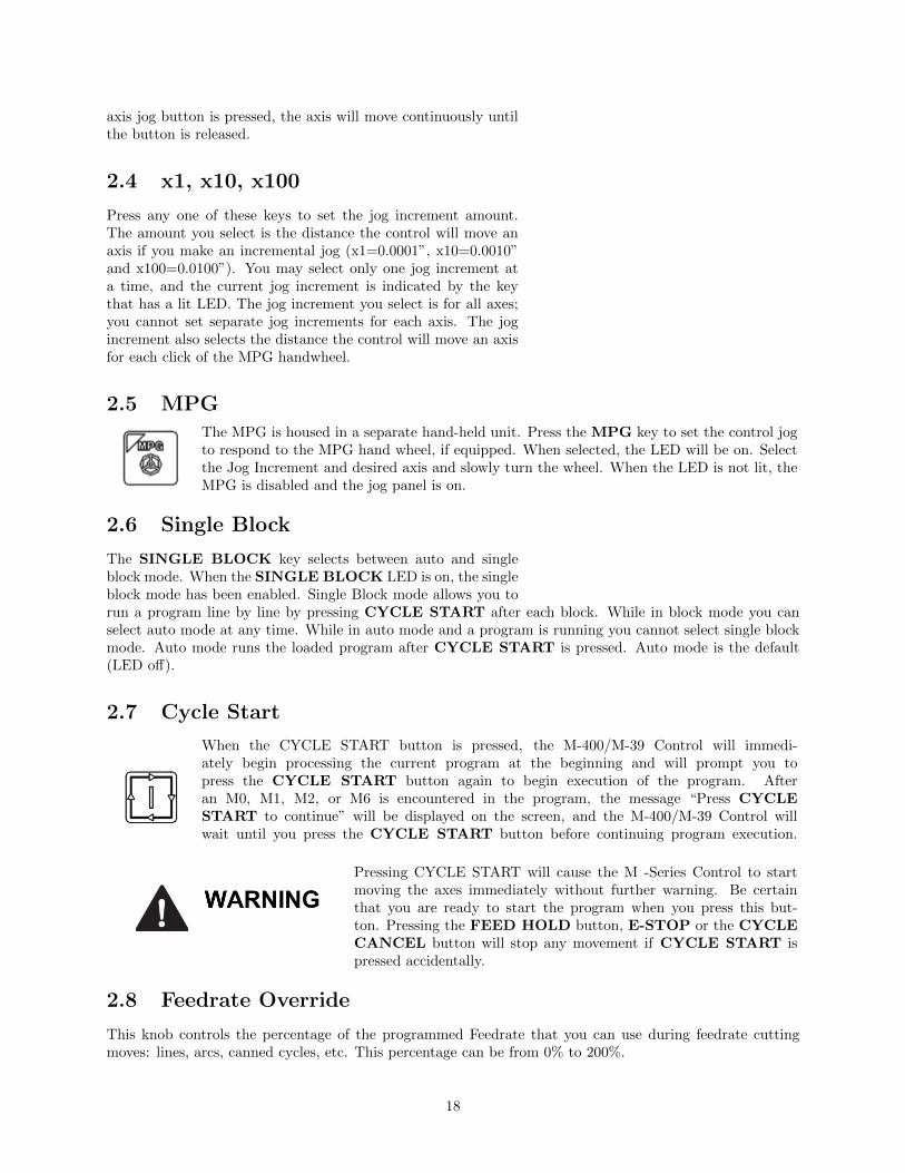
2.7 Cycle Start
When the CYCLE START button is pressed, the M-400/M-39 Control will immedi-ately begin processing the current program at the beginning and will prompt you topress the CYCLE START button again to begin execution of the program. Afteran M0, M1, M2, or M6 is encountered in the program, the message “Press CYCLESTART to continue” will be displayed on the screen, and the M-400/M-39 Control willwait until you press the CYCLE START button before continuing program execution.
Pressing CYCLE START will cause the M -Series Control to startmoving the axes immediately without further warning. Be certainthat you are ready to start the program when you press this but-ton. Pressing the FEED HOLD button, E-STOP or the CYCLECANCEL button will stop any movement if CYCLE START ispressed accidentally.
2.8 Feedrate Override
This knob controls the percentage of the programmed Feedrate that you can use during feedrate cuttingmoves: lines, arcs, canned cycles, etc. This percentage can be from 0% to 200%.
18

The Feerate Override knob will not work during tapping cycles (G74and G84) .
2.9 Feed Hold
Feed Hold decelerates motion of the current movement to a stop, pausing the job that is currently running.Pressing CYCLE START will continue the movement from the stopped location.
Feed Hold is temporarily disabled during tapping cycles (G74 andG84) , and automatic tool changes (M6).
2.10 Tool Check
Press TOOL CHECK while no program is running to move the Z-axis to its home position/G28 position.Press TOOL CHECK while a program is running to abort the currently running program. The controlwill stop normal program movement, pull Z to its home position, clear all M-functions, and automaticallydisplay the Resume Job Screen. From the Resume Job Screen, you can change tool settings (height offsets,diameter offsets, etc.) and resume the job with the new tool settings.
2.11 Cycle Cancel
Press CYCLE CANCEL to abort the currently running program. The control will stopmovement immediately, clear all M-functions, and return to the Main Screen. It is recom-mended that you press FEED HOLD first before CYCLE CANCEL. If you press CYCLECANCEL, program execution will stop; if you wish to restart the program you must rerunthe entire program or use the search function. See search function operation in Chapter 3 orChapter 6.
2.12 Emergency Stop
EMERGENCY STOP releases the power to all the axes and cancels the current job immediately uponbeing pressed. EMERGENCY STOP also resets certain faults if the fault condition has been fixed orcleared.
On some machines, vertical axes (such as Z and/or W) may start to move due togravity pulling it down when motor power is cut due to EMERGENCY STOPbeing pressed.
2.13 Spindle CW/CCW
The SPINDLE CLOCKWISE/COUNTERCLOCKWISE keys determine thedirection the spindle will turn if it is started manually. If the spindle is started auto-matically, the direction keys are ignored and the spindle runs according to the program.The default direction is CW.
19

2.14 Spindle Speed +
Pressing this key will increase the spindle speed by 10% of the commanded speed in Autospindle mode, limited by the maximum speed or 200% of commanded speed, whichever is less.For manual spindle mode, the spindle speed is increased by 5% of the maximum spindle speed(up to the maximum speed). The LED is on if the spindle speed is set above the 100% point.
2.15 Spindle Speed 100%
Pressing this key will set the spindle speed at the 100% point, which is defined as the commandedspeed in Auto spindle mode, or 1/2 the maximum spindle speed in manual mode. The LEDwill be on when the spindle is at the 100% point.
2.16 Spindle Speed -
Pressing this key will decrease the spindle speed by 10% of the commanded speed in Autospindle mode, limited to 10% of commanded speed. For manual spindle mode, the spindlespeed is decreased by 5% of the maximum spindle speed down to 5% of maximum. The LEDis on if the spindle speed is set below the 100% point.
2.17 Spindle Auto/Man
This key selects whether the spindle will operate under program control (automatic) or under operatorcontrol (manual). When the LED is lit, the spindle is under automatic control. If the LED is off, the spindleis under manual control. Pressing the SPINDLE (AUTO/MAN) key will toggle it from AUTO to MANand back again. The default is AUTO mode.
2.18 Spin Start
Press the SPIN START key when manual spindle mode is selected to cause the spindle tostart rotating. Press SPIN START when automatic mode is selected to restart the spindle ifit has been paused with SPIN STOP.
2.19 Spin Stop
Press the SPIN STOP key when manual spindle mode is selected to stop the spindle. PressSPIN STOP when automatic mode is selected to pause spindle rotation and can be restartedwith SPIN START.
SPIN STOP should only be pressed during FEED HOLD or when a program isNOT running.
2.20 Coolant Auto\Manual
This key will toggle between automatic and manual control of coolant. In automatic mode,M7 (Mist) and M8 (Flood) can be used in G-code programs to select the coolant type to beenabled. In manual mode, flood coolant and mist coolant are controlled by separate keys.Note: When switching from automatic to manual mode, both flood and mist coolants areturned off automatically.
20

2.21 Coolant Flood
In manual coolant control mode, flood coolant can be toggled off and on by pressing this key.The LED will be on when flood control is selected in either automatic or manual mode.
2.22 Coolant Mist
In manual coolant control mode, mist coolant can be toggled off and on by pressing this key.The LED will be on when mist control is selected in either automatic or manual mode.
2.23 Auxiliary Function Keys (AUX1 - AUX12)
The M-Series jog panel has 12 auxiliary keys (9 labeled), some of which may be defined by customizedsystems.
2.24 Notes About Operator Panels
The behavior of the control system in response to the functions listed above for the M-Series jog panel isdependent upon optional software options, the PLC program, machine parameters, and hardware wiring ofthe system. It is possible that the functioning explained in this chapter does not apply to a particular controlsystem or that it may differ in some aspects.
2.25 Keyboard Jog Panel
The PC keyboard may be used as a jog panel. Press Alt-J to display and enable the keyboard jog panel.The jog panel appears as shown below:
Some controls, such as coolant on/off, spindle on/off, feedrate and spindle override will work without the”jog panel” being displayed but for full functionality (and jogging) of the keyboard jog panel, the ”jogpanel” must be displayed on the screen. To enable keyboard jogging, parameter 170 must be set to ”1”.
The status window in the upper right corner of the screen displays the jogging mode(continuous/incremental), incremental step size, and jog speed (fast/slow). In continuous mode, the jog
21
keys start movement when pressed and movement stops when you release the key. In incremental mode,the axis will move the indicated incremental step amount.
As shown in the picture above, the jog keys are located in the cursor key block to the right of the mainkeyboard and to the left of the numeric keypad. If a jog key controls an axis, it will be overlaid with theaxis symbol (”X”, ”Y”, etc.) The jog keys are the Arrow Keys, Page Up, and Page Down.
The remaining keys are described below:
Legend Key(s) Function Description Availability (Notes)
– Alt JStart/ExitPanel
Invokes or exits the jog panel.Always, with few ex-ceptions.
Alt S Cycle Start Same as Cycle StartAlways, with few ex-ceptions.
Esc Cycle Cancel Same as Cycle Cancel.During a job run; Oth-erwise, Esc is used toexit menus.
Ctrl F1-F12 Aux 1-12
Executes the corresponding Auxfunction and signals the PLC. Acustom PLC program is requiredto act upon jog panel signals.
Always, with few ex-ceptions.
Ctrl MToggle AutoCoolant
Toggles coolant mode betweenauto and manual.
Always, with few ex-ceptions.
Ctrl NTurns on/offFlood
Toggles Flood coolant if in man-ual mode.
Always, with few ex-ceptions.
Ctrl KTurns on/offMist
Toggles Mist coolant if in manualmode.
Always, with few ex-ceptions.
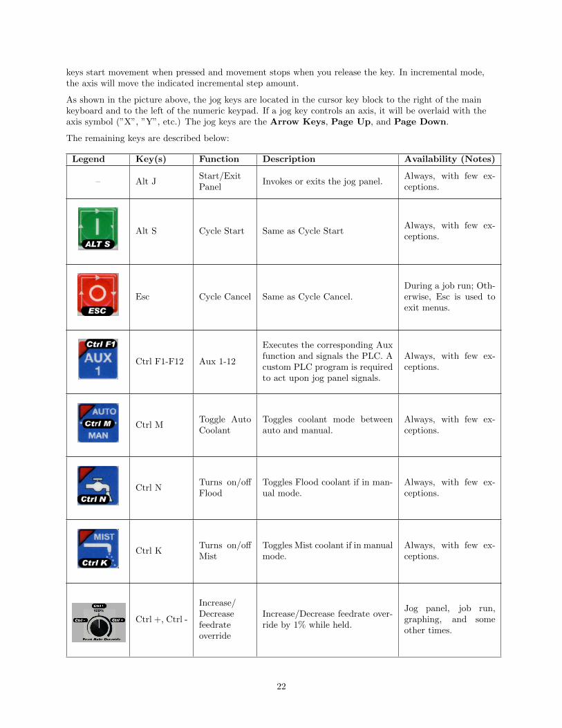
Ctrl +, Ctrl -
Increase/Decreasefeedrateoverride
Increase/Decrease feedrate over-ride by 1% while held.
Jog panel, job run,graphing, and someother times.
22

Legend Key(s) Function Description Availability (Notes)
Ctrl CSelects CWSpin
Selects CW Spin direction inman mode.
Always, with few ex-ceptions.
Ctrl WSelects CCWSpin
Selects CCW spin direction inman mod.e
Always, with few ex-ceptions.
Ctrl AToggleSpindle Au-to/Manual
Toggles between automatic andmanual spindle operation mode
Always, with few ex-ceptions.
Ctrl S Spin StartStarts spindle in selected direc-tion if in manual mode.
Always, with few ex-ceptions.
Ctrl Q Spin StopSTOPS spindle regardless ofauto or manual mode.
Always, with few ex-ceptions.
Ctrl >SpindleOverride+1%
Increase the spindle override by1% while held.
Always, with few ex-ceptions.
Ctrl <SpindleOverride-1%
Decrease the spindle override by1% while held.
Always, with few ex-ceptions.
Ctrl T Tool Check Preforms a tool check.Always, with few ex-ceptions.
23

Legend Key(s) Function Description Availability (Notes)
Ctrl IIncremental/ContinuousJog Selection
Toggles incremental or continu-ous jog mode.
Available most timesthat jogging is avail-able.
Ctrl BSelects Sin-gle BlockMode
Selects Single Block ModeAlways, with few ex-ceptions.
Delete/InsertDecrease/Increases Jogincrement
Decreases/Increases current jogincrement to the next availableincrement.
Always, with few ex-ceptions.
Right Arrow X+ JogWith on screen jogpanel displayed.
Left Arrow X- JogWith on screen jogpanel displayed.
Up Arrow Y+ JogWith on screen jogpanel displayed.
Down Arrow Y- JogWith on screen jogpanel displayed.
Page Up Z+ JogWith on screen jogpanel displayed.
Page Down Z- JogWith on screen jogpanel displayed.
Home 4th+ JogWith on screen jogpanel displayed.
24
Legend Key(s) Function Description Availability (Notes)
End 4th- JogWith on screen jogpanel displayed.
2.26 MDI and the Keyboard Jog Panel
Many of the keys used by the keyboard jog panel are also possible commands to MDI. To use the keyboardjog panel functions in MDI, you must press Alt J. You may jog; use the handwheels, or any other jogpanel function. Press Alt J or Esc to return to MDI.
2.27 Keyboard Shortcut Keys
A computer style keyboard is supplied with most systems. This keyboard can be used as a jog panel. Thekeyboard jog panel has many “hot keys”. Hot keys are keys that can be used at almost any time, with fewexceptions. Some menus may prohibit their use. Hot keys used in the CNC software are listed below:
2.27.1 ALT+D — WCS/Machine Coordinates
Switch DRO display between current WCS position and current machine position.
2.27.2 ALT+E — Generate Screenshot
If the value of parameter 389 is greater than 0, pressing the ALT+E key combination generates a screen shotand saves it as screenshot-nnn.png, where nnn is a three digit number starting at 000 and incrementingupward each time you take a screenshot. Note that when you restart the CNC software, the numberingstarts over at 000.
2.27.3 ALT+I — Live PLC I/O
Pressing ALT+I brings up the live PLC I/O display screen (see the image below). In this screen you mayview the real-time status of all the different inputs, outputs, etc. Use the arrow keys and the F11 and F12
keys to navigate the live PLC I/O screen. With proper PLC support, pressing CTRL+ALT+I allows you totoggle the value of inputs 1 through 80. Similarly, pressint CTRL+ALT+F allows you to toggle outputs.
25
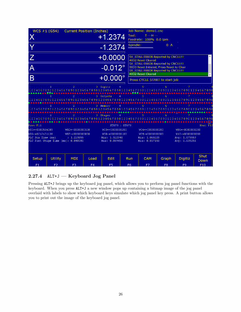
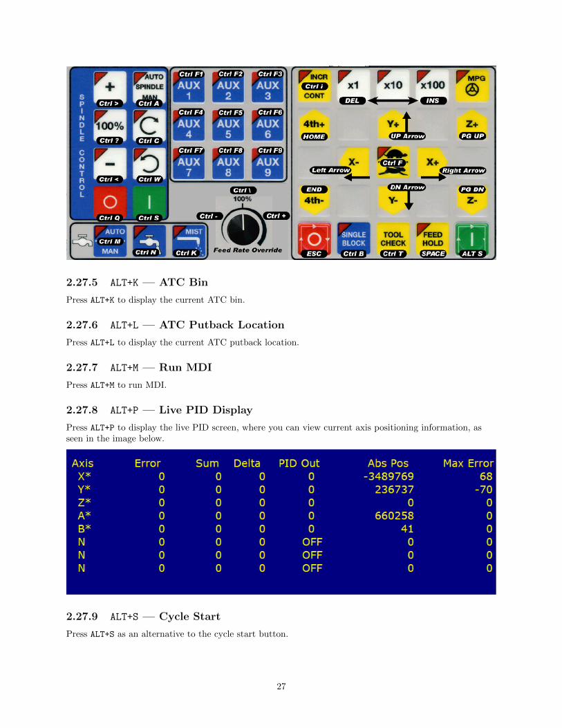
2.27.4 ALT+J — Keyboard Jog Panel
Pressing ALT+J brings up the keyboard jog panel, which allows you to perform jog panel functions with thekeyboard. When you press ALT+J a new window pops up containing a bitmap image of the jog paneloverlaid with labels to show which keyboard keys simulate which jog panel key press. A print button allowsyou to print out the image of the keyboard jog panel.
26
2.27.5 ALT+K — ATC Bin
Press ALT+K to display the current ATC bin.
2.27.6 ALT+L — ATC Putback Location
Press ALT+L to display the current ATC putback location.
2.27.7 ALT+M — Run MDI
Press ALT+M to run MDI.
2.27.8 ALT+P — Live PID Display
Press ALT+P to display the live PID screen, where you can view current axis positioning information, asseen in the image below.
2.27.9 ALT+S — Cycle Start
Press ALT+S as an alternative to the cycle start button.
27

2.27.10 ALT+T — Temperature Display
Press ALT+T to display the current temperatures for each axis in the message window.
2.27.11 ALT+V — Display CNC Software Version Info
Press ALT+V to display CNC12 software version information (the same information found when pressing F1from the main menu).
2.27.12 ALT+1, ALT+2, . . . , ALT+0 — Select WCS
Press ALT+1, ALT+2, . . . , ALT+0 to cycle through the first ten work coordinate systems.
2.27.13 ALT+- — Select Previous WCS
Press ALT+- to select the previous WCS.
2.27.14 ALT+= — Select Next WCS
Press ALT+= to select the next WCS.
2.27.15 ALT+F10 — Exit CNC12
Press ALT+F10 (in the utility menu only) to exit CNC12.
2.27.16 CTRL+D Swap DRO and Distance-to-Go DRO
Press CTRL+D to swap the positions of the DRO and the Distance-to-Go DRO.
2.27.17 CTRL+E — Launch PLC Detective
Press CTRL+E to launch the PLC Detective application.
2.27.18 CTRL+H — Enable G-Code Display
If a job is running and the G-Code display is hidden (perhaps behind the Live PLC I/O or Live PIDdisplay screens) press CTRL+H to show the G-Code display.
2.27.19 CTRL+I — Save PLC state to file.
If you are in the Live PLC I/O display screen (accessible by pressing ALT+I), then pressing CTRL+I willprint the current PLC I/O state to a file titled plcstate.txt.
2.27.20 CTRL+Q — Probing Cycles History
If you have run a probing cycle (found in the F9 Digitize → F4 Probe screen), then the probing cycle hasbeen recorded so that you may access the positions you probed. Press CTRL+Q to view this history. Awindow will pop up (as seen in the picture below) where you can enter a description, delete any probinghistory you don’t wish to keep, or copy the positions of that probing cycle to the clipboard. Click anywhereoutside of that window, or press CTRL+Q again, to close the probing cycles history.
28

2.27.21 SHIFT+F1 — Switch to Old Style Graphics Backplot
When you are in the accelerated backplot, press SHIFT+F1 to switch to the old style graphics backplot thatdoes not use OpenGL.
2.27.22 SHIFT+F2 — Erase Log File
From the Utility → Logs → Errors (or Stats) screen, press SHIFT+F2 to erase the log file. You will bepresented with a confirmation dialog before the log file is deleted.
2.27.23 CTRL+ALT+X — Go to Shutdown Screen
From the main menu, pressing CTRL+ALT+X will take you to the CNC12 shutdown screen.
29

Chapter 3
CNC Software Main Screen
F1 - Setup: Used to set part zeroes, set or change tool offsets, and change the control configuration.
F2 - Load: Use this menu to load a job.
F3 - MDI: The MDI menu allows you to a single line command such as: G1 X2 Y3 F20
F4 - Run: Use the Run menu to search and run a job from a specific line, resume a job after it has beencanceled or to change the way a job runs.
F5 - CAM: Use the CAM menu to program parts.
30

F6 - Edit: Brings up a G-code (text) editor that allows you to edit the currently loaded job.
F7 - Utility: View available software options, backup part and configuration files, create new directories,and import/export files to and from external locations.
F8 - Graph: Graphs the toolpath of the currently loaded part program.
F9 - Digitize: Displayed only if the Digitizing option has been purchased. Used to Digitize (reverseengineer) parts.
F10 - Shut down: Power off control. Shutting down your machine without using this menu may damageyour control.
3.1 F1 - Setup Menu
F1 - Part: This key displays the Part Setup menus that are explained in Chapter 4.
F2 - Tool: This key displays the Tool Setup menus that are explained in Chapter 5.
F3 - Config: This key displays the Configuration menu that is explained in Chapter 14.
F4 - Feed: This key displays the Feed menu that is discussed in Chapter 6.
F5 - 3rd Axit Toggle: This key will only be displayed if machine parameter 130 is set. See Chapter 14for configuration options.
F6 - 4th Axis Toggle: This key will only be displayed if machine parameter 131 is set. See Chapter 14for configuration options.
31

F7 - ATC: This key will only be displayed if machine parameter 6 is set to 1.0. It has the same effect asthe F7 - ATC key in the Tool menus. It will prompt you for a tool number and then perform theactions required for an automatic tool change cycle.
F8 - Smoothing Setup: This gives you acces to the Smoothing Setup Menu which provides a simplifiedway of choosing parameters for the Smoothing module. See Chapter 14 under “Smoothing SetupMenu”.
3.2 F2 - Load Job Menu
F1 - G code/ICN: Allows the user to change which types of files are displayed.
F2 - USB/LAN: Select a different drive from which to load files.
F3 - Details: Displays file details including: Programmer, Description and Date Modified.
F4 - Show Recent: Displays a list of the 15 most recently loaded jobs.
F5 - Date/Alpha: Toggles the current view of files to be sorted alphabetically or by date modified.
F6 - Edit: Opens selected file in editor.
F7 - Help: Displays on screen help for the load menu.
F8 - Graph: Backplots (graphs) the selected file.
F9 - Advanced: Displays a unified file and device browser similar to Windows Explorer. (If Parameter 4is set to 5, this is the default menu state).
32

Other Keys:
Page Up - Move the cursor backward one page.
Page Down - Move the cursor forward one page.
End - Select the last file in the list.
Home - Select the first file in the list.
Arrow Keys - Navigate items.
*Note: The path and/or file name may also be selected by typing the path or path and file name. Awindow will open automatically when you begin typing.
3.3 F3 - MDI
MDI mode allows you to directly enter M and G-codes one line at time. After entering the M and Gcodes youwish to run, press cycle start to have the controller execute the command. When, the command has finishedexecuting the command, it will prompt you for another line. When you are, finished entering commands,press ESC.
Navigation through previous commands is possible by pressing the ↑ UP ARROW key and the ↓ DOWNARROW key. Once selected, you may modify the command using the← LEFT or→ RIGHT arrow key.
33

Press the ENTER key or Cycle Start to execute.
Examples:
Block? G92X0Y0 ;Set the current XY position to 0,0
Block? M92 /Z ;Move the Z to the positive limit.
Block? M26 /Z ;Set the current Z position as Z home.
34

3.4 F4 - Run Menu
F2 - Search: You can resume a job by searching for the line, tool, or a block number.
F3 - Repeat: Toggles Job Repeat. Will repeat the current program when a job is finished.
F4 - Bock Skips: Turns on and off block skips in part programs.
F5 - Single Block: Program runs in single block mode when turned on.
F6 - Stops: Turns on and off optional stops (M01) in part programs.
F8 - Graph: Graphs tool path of currently loaded program
F9 - Rapid: Turns on and off rapid override function
F10 - RTG: Turns on and off Run Time Graphics
*Note: For more information on these options, please see Chapter 6.
35
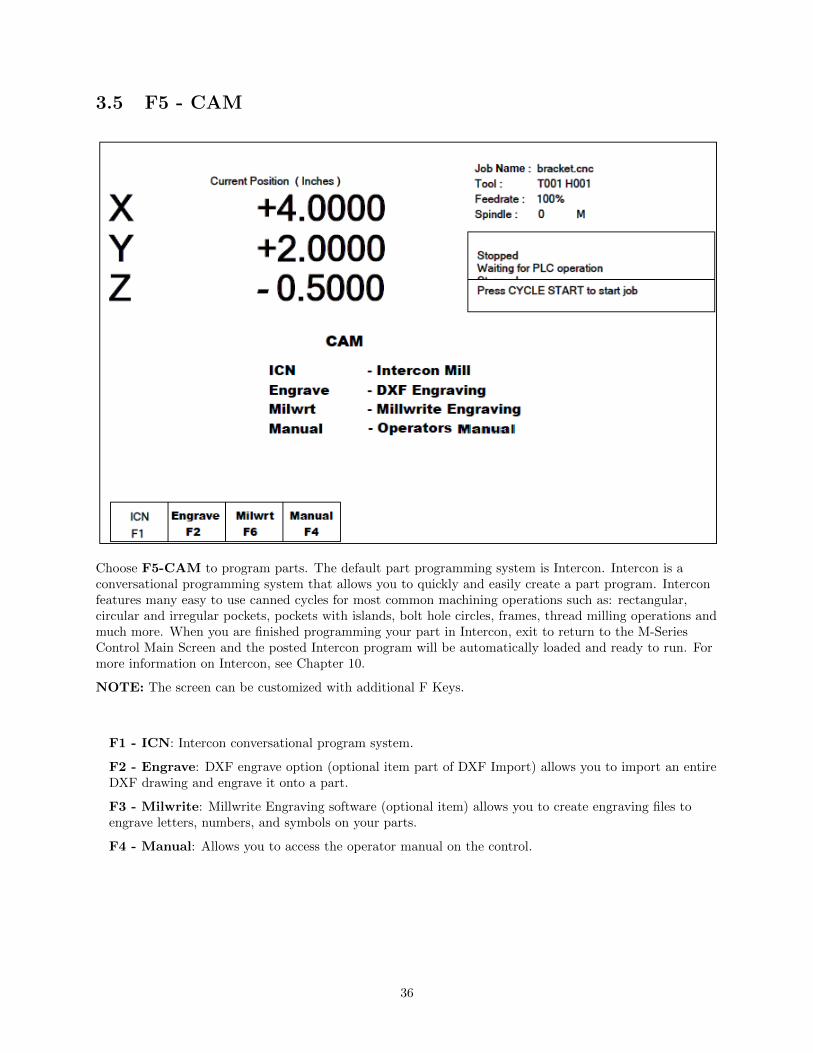
3.5 F5 - CAM
Choose F5-CAM to program parts. The default part programming system is Intercon. Intercon is aconversational programming system that allows you to quickly and easily create a part program. Interconfeatures many easy to use canned cycles for most common machining operations such as: rectangular,circular and irregular pockets, pockets with islands, bolt hole circles, frames, thread milling operations andmuch more. When you are finished programming your part in Intercon, exit to return to the M-SeriesControl Main Screen and the posted Intercon program will be automatically loaded and ready to run. Formore information on Intercon, see Chapter 10.
NOTE: The screen can be customized with additional F Keys.
F1 - ICN: Intercon conversational program system.
F2 - Engrave: DXF engrave option (optional item part of DXF Import) allows you to import an entireDXF drawing and engrave it onto a part.
F3 - Milwrite: Millwrite Engraving software (optional item) allows you to create engraving files toengrave letters, numbers, and symbols on your parts.
F4 - Manual: Allows you to access the operator manual on the control.
36

3.6 F6 - Edit
This key causes the control to load the current job into a text editor for viewing and/or editing.
When editing, care must be taken to save the file and to quit and exit the text editor before running thefile (the current job). Modifying a file that is currently running as the current job is dangerous and willcause unexpected results. It is best practice to not edit any files while the machine is moving.
Editing a file (modifying and saving) while the machine is moving cancause personal injury or machine damage.
Also, note that the C:\CNCM directory contains configuration files and binary data. DO NOT edit thesefiles. Doing so can cause loss of data and serious malfunctions.
Do not edit configuration data located in the C:\CNCM directory. Doingso can cause personal injury or machine damage.
3.7 F7 - Utility
From the utility menu you can view available software options, perform diagnostics, backup part and config-uration files, create new directories and import or export files to and from external locations. For furtherinformation please see Chapter 7.
F2 - Restore Report: Update your control’s configuration with a report.zip file.
F3 - Backup Files: Backup your CNC and ICN files.
F4 - Restore Files: Restore your CNC and ICN files.
F5 - File Ops: Use this menu to perform file and directory operations.
F6 - User Maint: Perform user maintenance.
F7 - Create Report: Generates a backup of system configuration files called report.zip.
F8 - Options: Shows the software options that you have purchased or added to your control.
F9 - Logs Shows the messages and errors that have been logged by the control.
37

3.8 F8 - Graph
This function plots the tool path of the current program loaded. Canned drilling cycles are shown ingray. Rapid traverse movements are shown in red. Feedrate movements are shown in yellow and cuttercompensated moves are in gray.
F1 - 2D/3D: Press this key to view your part isometrically (3D). An axis pointer indicates the currentdirection of the view. To return back to the tri-planar view, press F1 again.
F2 - View/Rotate: Press this key to change the planar view of your part. The view is indicated byTOP, RIGHT, or FRONT shown at the top of the screen. In 3D Mode, use this key in 3D mode to rotateyour part, using the keyboard arrow keys to rotate any in direction.
F3 - Range: Press this key to set the range of line numbers or block numbers to graph.
F4 - Time: Press this key to estimate the time needed to create part. It takes into account accelerationsand decelerations, but neglects tool change times.
F5 - Redraw: Press this key to redraw the part at any time.
F6 - Pan: Press this key to move the part around the screen. Once pressed, use the crosshairs to pick alocation of the part that will redraw at the center of the screen. Once a section is selected, press F6 againto continue panning.
F7 - Zoom In: Press these keys to zoom into the part relative to the center of the screen.
F8 - Zoom Out: Press these keys to zoom away from the part relative to the center of the screen.
F9 - Zoom All: Press this key to view the entire part fit inside the screen.
*Note: Use the FEEDRATE OVERRIDE knob to control the speed of the graphing. To pause the toolpath, turn the knob counter-clockwise until it stops. Turn the knob clockwise to resume drawing. On theoffline demo software, the simulated FEEDRATE OVERRIDE knob is controlled by pressing either Ctrl +or Ctrl –.
38
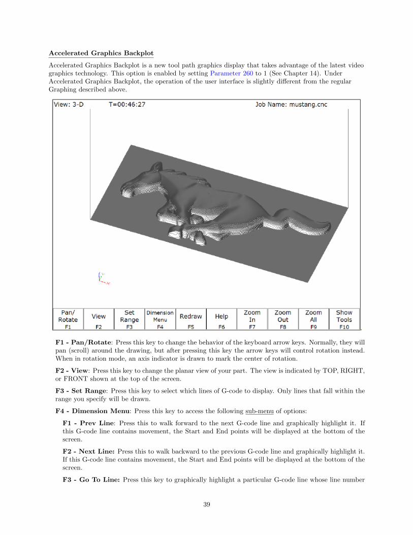
Accelerated Graphics Backplot
Accelerated Graphics Backplot is a new tool path graphics display that takes advantage of the latest videographics technology. This option is enabled by setting Parameter 260 to 1 (See Chapter 14). UnderAccelerated Graphics Backplot, the operation of the user interface is slightly different from the regularGraphing described above.
F1 - Pan/Rotate: Press this key to change the behavior of the keyboard arrow keys. Normally, they willpan (scroll) around the drawing, but after pressing this key the arrow keys will control rotation instead.When in rotation mode, an axis indicator is drawn to mark the center of rotation.
F2 - View: Press this key to change the planar view of your part. The view is indicated by TOP, RIGHT,or FRONT shown at the top of the screen.
F3 - Set Range: Press this key to select which lines of G-code to display. Only lines that fall within therange you specify will be drawn.
F4 - Dimension Menu: Press this key to access the following sub-menu of options:
F1 - Prev Line: Press this to walk forward to the next G-code line and graphically highlight it. Ifthis G-code line contains movement, the Start and End points will be displayed at the bottom of thescreen.
F2 - Next Line: Press this to walk backward to the previous G-code line and graphically highlight it.If this G-code line contains movement, the Start and End points will be displayed at the bottom of thescreen.
F3 - Go To Line: Press this key to graphically highlight a particular G-code line whose line number
39

you specify. If this G-code line contains movement, the Start and End points will be displayed.
F4 - Measure: Use this feature to measure between any 2 selected points. To do this, use a mouse tomove the pointer over the first point and then press F4 - Measure to anchor the first point. Then usethe mouse to move the pointer to the second point. As you move the mouse towards the second point,you will notice an Offset and Measurement display changing dynamically as you move the mouse. Alsoyou may notice some ”snap to” effects as you move the pointer close to start and end points of entitiesthat make up your program.
F5 - Redraw: Press this key to redraw the part slowly, which can be useful for visualizing the movementsthe machine will make. While the display is being redrawn, you can use the feedrate override knob toadjust the rate at which it is being drawn. If you don’t have a feedrate override knob, the + and - keyscan be used to adjust the rate. Pressing F5 again will cancel this mode.
F6 - Hide Rapids: Press this key to hide rapid movements. Press it again to show them.
F7 - Zoom In: Press these keys to zoom into the part relative to the center of the screen.
F8 - Zoom Out: Press these keys to zoom away from the part relative to the center of the screen.
F9 - Zoom All: Press this key to fit the entire part inside the screen.
F10 - Show Tools: Press this key to show the tools menu, which allows you to highlight movements ofcertain tools. Press this key again to hide the tools menu.
Spacebar - Measure: Press this key to take a measurement between two points. In a 2D view, thismeasurement will be a 2D measurement. In a 3D view, it will be a 3D measurement (and the measurementwill only be valid if the crosshairs are snapped to a line of the tool path).
*Note: If you have a mouse or touch screen attached to your device, you can use that to control thegraphing window. Holding the left mouse button allows you to drag the part across the screen, while theright mouse button controls rotation of the part. Spinning the mouse wheel (or holding both left and rightbuttons) zooms in and out. Double clicking on a feedrate movement will center the camera on thatmovement (which is very useful) and also tells you the length of that movement. For touchscreenoperation, use the F1 key to switch between Pan and Rotate modes.
40

3.9 F9 - Digitize
Use this to bring up the Digitize screen. This screen allows you to set up and run touch probe digitizing.See Chapter 8 for a detailed description of the digitizing operation.
3.10 F10 - Shutdown
Use to enter the Shutdown menu. This menu allows you to park the machine, power off the control, start acommand window, or exit CNC software.
F1 - Park: Use this to park the machine at the end of the day for quicker machine homing at startup.Once F10- Park is selected, The CYCLE START key must be press to start machine movement. The parkfeature homes each axis, at the maximum rate, to 1/4 of a motor revolution from its home position.
F2 - Poweroff : Use this to properly shutdown the control. With most controls, this action turns off thecontrol once the system has prepared itself to be shutdown. Just like a desktop computer, the controlshould be properly shutdown before turning off the power in order to reduce the risk of corrupting dataon the hard drive.
NOTE: This will only turn off the control. The machine itself will still need to be manually turned off.
F6 - System Prompt: This brings up the command line interface. Type the command exit to exit thecommand window.
F9 - Exit CNC11: Use this to exit the CNC control software.
41

Chapter 4
Part Setup (F1 from Setup)
The Part Setup menu is used to set the part position or the coordinate system origin for the part.
F1 - Next Axis Will toggle to the next axis. If changes were made to the current axis, but not yet accepted,they will be discarded.
F2 - Auto Uses probe to automatically measure and set part position. Make sure your probe height anddiameter offsets are set for the tool number you assigned to the probe and that parameter 12 is set tothat tool number. See Chapter 9 for more details.
F3 - Probe Will open the probing operations menu. See Chapter 9 for details.
F4 - Prev WCS Will select the previous work coordinate. The position being set will only affect thecurrently selected work coordinate.
F5 - Next WCS will select the next work coordinate. The position being set will only affect the currentlyselected work coordinate.
42

F6 - CSR Will open the CSR menu, which can be used to automatically detect coordinate system rotation.This function key appears only when the software option for Coordinate System Rotation is unlocked.
F7 - WCS Table Will open the Work Coordinate System (WCS) Configuration screen. See the WorkCoordinate System Configuration section later in this chapter for a complete description.
F8 - Set Will accept the position for the current axis, correcting for edge finder diameter based on theapproach direction if appropriate. It will not automatically advance to the next axis.
4.1 Operation Description
Setting the part position establishes a coordinate system with an origin at the part zero.
The F1 - Next Axis option selects the axis to be defined next. This field toggles between axis X, Y, Z,4th, and 5th Axes. For each axis you will see a graphic description of the parameters to be entered, as wellas the corresponding fields.
4.1.1 Setting up X or Y AXIS
Set Part Position1) Select Axis with F12) Jog to Touch Off on Part3) Edit the Value if Necessary4) Press F10 to Set Position
Axis Part Edge ApproachPosition Finder From
DiameterX 0.0000 0.0000 Left(-)
Part Position: enter the value of your part zero position or the offset.
Edge Finder Diameter: enter the diameter of the tool, or edge finder you are using to determine the partzero. The value entered is stored.
Approach From: Toggle the direction the edge finder or probe is approaching the part.
*Note - Use the arrow keys to toggle between Part Position, Edge Finder Diameter, and Approach Fromoptions.
43

4.1.2 Setting up the Z AXIS
Set Part Position1) Select Axis with F12) Jog to Touch Off on Part3) Edit the Value if Necessary4) Press F10 to Set Position
Axis Part ToolPosition Number
Z 0.0000 0
Part Position: enter the value of your part zero position or the offset.
Tool Number: enter the tool number from the Tool Library that corresponds to the tool being used. Whenthe Tool Number field is set to a value other than zero, the controller uses the Height Offset for that toolfrom the Tool Library to calculate the actual position.
Example 1 (You are using the reference tool to find the Z-axis part zero):Set Tool Number to 0: setting the Tool Number to zero tells the controller that you are using the referencetool.
Example 2 (You are using a tool other than the reference tool, and not a ball nose cut-ter):Set Tool Number to a number tool that is assigned in the tool library (make sure its height offset is set).
Example 3 (You are using a ball nose cutter, other than the reference tool):Set Part Position to the position of the surface plus the nose radius of the ball nose cutter, set Tool Numberto the number this tool is assigned in the tool library.
The Tool and Offset libraries must be up to date before setting the Z-axis Part Zero.
4.1.3 Setting up the 4th or 5th AXIS***
Position: enter the value of your part zero position or the offset.
Standoff Distance: this field is a generic parameter. Its physical meaning will depend on the specific natureof your machine’s fourth axis. It is the distance between the center of the tool and the point at which thetool is touching the part surface.
44

Approach From: enter the direction the edge finder is approaching the part from. Enter the correct di-rection given the nature of your 4th-Axis.
4.1.4 Using Multiple Work Coordinate Systems
If you will be using multiple work coordinates, you must set the part position separately for each work coor-dinate. Follow the instructions above to set the position for each axis in the first coordinate system. Thenmove to the next fixture and press F6 – Prev WCS to select the previous work coordinate or F7 – NextWCS to select the next work coordinate. The currently selected coordinate system is displayed below theaxis picture on the Part Setup screen. It is also displayed above the DRO at all times. For a description onsetting up each work coordinate, see the Work Coordinate System Configuration section later in this chapter.
This procedure does NOT apply to tilt table setup.
4.2 Part Setup Examples
Example 1: Setting the X-axis Part Zero with no offset (See diagram below)
If you wanted the left edge of the part to be the origin for the X-axis:
1. Move the Edge Finder to the left edge of the part
2. Press F1 – Next Axis until the Axis label displays ’X’
3. Move the cursor to the Edge Finder Diameter field
4. Type .25 and press ENTER
5. Press SPACE until Left (-) is displayed
6. Press F10 - Set to accept the values
45

Axis Part Edge ApproachPosition Finder From
DiameterX 0 0.25 Left (-)
Since no offset is being applied, Position is zero. The Edge Finder is approaching the part from the -Xdirection and has a diameter of .25 inches. Once this data is entered and F10 - Set is pressed, the X-axisDRO display will read -0.125. This means the center of the Edge Finder is sitting to the left (minus) of thepart by 0.125 inches (half of the Edge Finder Diameter).
This value is computed by: Position (Approach from) Edge Finder Diameter / 2.
Where (Approach from) is the sign of the approach direction. In other words, if the approach directionis minus, then the value is: Position - Edge Finder Diameter / 2 = 0.0 - .25 / 2 = -0.125
Example 2: X-Axis origin offset into part 1 inch.
If you wanted the origin offset 1 inch into the part:
1. Move the Edge Finder to the left edge of the part
2. Press F1 – Next Axis until the axis field displays ’X’
3. Move the cursor to the Part Position field
4. Type -1 and press ENTER
5. Type 0.25 and press ENTER
6. Press SPACE until Left (-) is displayed
7. Press F10 - Set to accept the value
Axis Part Edge ApproachPosition Finder From
DiameterX -1 0.25 Left (-)
The Position value is relative to the current position of the Edge Finder. Part position equals -1.0 since theEdge Finder is positioned 1 inch to the left (minus direction) of where you want the X-axis origin.
Another way to view the Part Position value is to assume the origin is already set at 1 inch into thepart. In this case, the Edge Finder would have to move -1 inches from where the origin is to get to the leftedge of the part.
46

The Edge Finder is approaching the part from the -X direction and has a diameter of .25 inches. Oncethis data is entered and F10 - Set is pressed, the X-axis DRO display will read -1.125. This means thecenter of the Edge Finder is sitting to the left (minus) of the origin by 1.125 inches. The X-axis origin isnow 1 inch into the part.
This value is computed by: Position (Approach from) Edge Finder Diameter / 2.
Where (Approach from) is the sign of the approach direction. In other words, if the approach directionis minus, then the value is:
Position - Edge Finder Diameter / 2 = -1.0 - .25 / 2 = -1.125
4.3 Work Coordinate Systems (WCS) Configuration
Press F9 – WCS Table from the Part Setup screen to display the Work Coordinates System (WCS) menu.The Work Coordinate Systems screen provides access to reference return points, coordinate system origins,and work envelope. Make sure your Home position has been set properly. Otherwise, the positions of eachcoordinate system will not be in the appropriate position.
When you enter the Work Coordinate System Configuration screen, the DRO display will automaticallyswitch over to machine coordinates as an aid to entering numbers. All the values on this screen are repre-sented in machine coordinates.
F1 - Reference Return Points Press this key access the menu that sets the reference return pointsfor the machine.
The reference return points are used with the G28 and G30 codes (see Chapter 12). They are specified inmachine coordinates. The Z coordinate of the first reference point is also used as a Z home position by theM2, M6, and M25 codes (see Chapter 13).
F2 - Origin Use this key to access the menu for specifying the locations (in machine coordinates) ofthe origins for all 18 work coordinate systems. Pressing F1 – Next Table will allow you to view the otherWCS (6 per page). This menu is a convenience and is not an absolute necessity for setting work coordinatesystem origins nor the CSR angles.
47

All coordinate systems are relative to Home position that is set during control power up. Note that while inthis screen, the DRO shows the actual machine position relative to Home, not the location relative to theWCS origin.
If the software option Coordinate System Rotation is unlocked, the CSR angle for each of the coordinatesystems can also be set. (This is an optional feature.)
For machines configured as an Articulated Head system with the TWCS feature enabled (set via Paramter166), the TWCS=Yes/No differentiates which WCS’s are transformed or not. See Transformed WCS laterin this chapter.
Note: A WCS can be ”locked out” from editing if you do not want it to be accidentally changed. SeeParameter 45 for more information.
F3 - Work Envelope Use the F3 – Work Envel key to specify the ‘+’ and ‘-‘work envelope locations(in machine coordinates) used in conjunction with the G22 G code. The X, Y, Z and I, J, K parametersspecified in the G22 G code are stored here, so subsequent G22 codes do not need to specify the limits unlessthey change.
Note: The work envelope will only work in programmed moves. You will still be able to jog outside the workenvelope.
4.4 Coordinate System Rotation (CSR)
Coordinate System Rotation saves you time when setting up your part. Rather than clamping your part andindicating the edge of the material to square it with the machine axes, you can use CSR to automaticallyrotate the coordinate system to the angle of the part or fixture that was probed. This allows you tocompensate for different orientations.
Simply clamp your part, and then probe two points along either the X or Y-axis of the material using the
48

process described below.
F1 - Orient is used to select the orientation for the CSR measurement. There are four possible orientations,which are: from the front (pictured above), the back, and the left and right sides.
F2 - Manual is used to determine the CSR angle without probing. The user jogs an edge finder to twopositions along one wall. These positions will be used for computing the CSR angle.
F3 - Zero Cur is used to set the CSR angle for the current WCS to zero.
F4 - Zero All is used to set all CSR angles to zero.
F5 - Probe Will open the probing operations menu. See Chapter 9 for details.
F6 - Prev WCS is used to cycle through the available WCS systems.
F7 - Next WCS is used to cycle through the available WCS systems.
F8 - MDI The MDI menu allows you to a single line command such as: G1 X2 Y3 F20
F9 - WCS Table is a shortcut to the Work Coordinate System Configuration Screen described above.
The instructions on how to perform a CSR measurement are numbered on the screen.Distance: The distance the X-axis (in front or back orientation) or Y-axis (in right or left side orientation)will move to probe the second point. If the distance is negative, the axis will be moved in the negativedirection.Clearance Amount: The distance the Z-axis will be moved upward when moving between the first probepoint and the second probe point. The clearance move will only be made when using the “Auto” option ofthe Movement between Points.
49

Movement Between Points: can be toggled between Jog and Auto modes. In Auto mode, the clearingmoves are made automatically as well as the move to the second point. In Jog mode, a prompt will bedisplayed in the center of the screen after the first point is probed.
4.5 Transformed WCS (TWCS=Yes)
This section only applies to Articulated Head machines with the TWCS feature enabled via Parameter 166(see Chapter 14 for more information on setting Parameter 166). On such a machine, when a WCS has asetting of TWCS=Yes, this is then called a transformed WCS (abbreviated as TWCS).
When a TWCS is selected, the DRO will show axis positions based on the TWCS’s frame of reference. Inother words, the shown positions are transformed based on the position of the B axis (5th axis).Furthermore, the WCS label will be shown as “TWCS” to indicate that the currently selected WCS isindeed transformed.
Also, when the Probing Cycles are run with a TWCS selected, the results shown will be based on theTWCS frame of reference.
Ordinary 3 axis moves types performed while running a CNC program with a TWCS selected will beautomatically transformed. Such move types include:
• G0, G1, G2, G3
• Protected move probing functions M115, M116, M125, M126
• Canned Cycles G73, G74, G76, G81, G82, G83, G84, G85, G89
• M25
• Moves that involve CSR and Cutter Compensation
However, moves that will not be transformed are:
• Homing moves M91/M92
• Move to switch M105/M106
• Move axis by counts M128
50
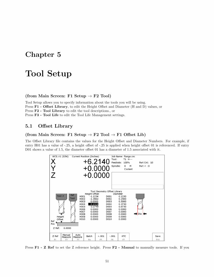
Chapter 5
Tool Setup
(from Main Screen: F1 Setup → F2 Tool)
Tool Setup allows you to specify information about the tools you will be using.Press F1 - Offset Library, to edit the Height Offset and Diameter (H and D) values, orPress F2 - Tool Library to edit the tool descriptions., orPress F3 - Tool Life to edit the Tool Life Management settings.
5.1 Offset Library
(from Main Screen: F1 Setup → F2 Tool → F1 Offset Lib)
The Offset Library file contains the values for the Height Offset and Diameter Numbers. For example, ifentry H01 has a value of -.25, a height offset of -.25 is applied when height offset 01 is referenced. If entryD01 shows a value of 1.5, the diameter offset 01 has a diameter of 1.5 associated with it.
Press F1 - Z Ref to set the Z reference height. Press F2 - Manual to manually measure tools. If you
51

purchased the Automatic Tool Measurement (TT1) option, press F3 - Auto to automatically measure toollengths. Press F5 - +.001 or F6 - -.001 to adjust the selected offset. If you have an automatic toolchanger installed, press F7 - ATC to change tools. Press F10 - Save to save changes and exit, or ESCto exit without saving changes. If you have both purchased the Automatic Tool Measurement (TT1) optionand also have an automatic tool changer installed, then you can press F4 - Auto to perform batch toolmeasuring, by entering a list of multiple tool numbers.
You can inspect and change any of the 200 Height Offset (H) values, and any of the 200 Diameter (D) values.In most cases you will use the automatic tool length measurement features described below to set H values,and you will enter D values manually, based on the known or measured diameters of your tools. mNote thatH01 and D01, H02 and D02, H03 and D03, etc. are displayed together on the same line for convenienceonly. The Height and Diameter Offset Numbers can be used independently; associations are made only inthe Tool Library.
Height Offset
This is the distance the control adjusts Z-axis positions when tool length compensation (G43 or G44) is usedwith a particular H value. For example, if H001 is -1.0 and the job contains G43 H1, then the CNC softwarewill shift all Z-axis positions down 1.0 to compensate for the shorter tool.
To edit the Height Offset entries move to the desired height offset number with the arrow keys, Page Up,Page Down, HOME, and END. You can choose to manually edit or automatically measure the value.
Height Offsets values are measured using the Z Reference position. The Z Reference position is the Z-axisposition when the tip of the reference tool is touching the work surface. The reference tool should always bethe longest tool.
The Height Offset value for end mills and drills is the difference between the Z-axis position when the tipof the tool is touching the work surface and the Z Reference position. The Height offset value for ball noseand bull nose cutters is the difference between the Z-axis position when the center of the tool is at the worksurface and the Z reference position. Because it is not possible to position the tool in this way, you mustinstead move the tip of the tool to the work surface, and then manually edit the value to subtract the toolnose radius.
To manually edit a Height Offset value, simply type the desired value and press ENTER.
To manually measure Height Offset values, use the following procedure:
Establishing the Z reference position
Press F1 - Z Ref to select the Z Reference setting function.
Insert the longest tool into the tool holder (you can use the jog keys or the TOOL CHECK key to assistyou).
Jog the tip of the tool down to the top of the work surface.
Press F10 - Save to save this Z Position as the Reference Position.
Measuring each tool height (Z position for tool minus Z position for Reference tool)
Insert the desired tool into the tool holder (Jog keys or the TOOL CHECK key can be used to assist you).
Jog the tip of the tool down to the top of the work surface.
If the tool is a drill or end mill, press F2 - Manual Measure to measure the height.
52
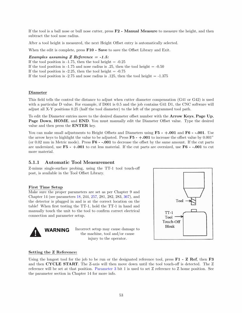
If the tool is a ball nose or bull nose cutter, press F2 - Manual Measure to measure the height, and thensubtract the tool nose radius.
After a tool height is measured, the next Height Offset entry is automatically selected.
When the edit is complete, press F10 - Save to save the Offset Library and Exit.
Examples assuming Z Reference = -1.5:If the tool position is -1.75, then the tool height = -0.25If the tool position is -1.75 and nose radius is .25, then the tool height = -0.50If the tool position is -2.25, then the tool height = -0.75If the tool position is -2.75 and nose radius is .125, then the tool height = -1.375
Diameter
This field tells the control the distance to adjust when cutter diameter compensation (G41 or G42) is usedwith a particular D value. For example, if D001 is 0.5 and the job contains G41 D1, the CNC software willadjust all X-Y positions 0.25 (half the tool diameter) to the left of the programmed tool path.
To edit the Diameter entries move to the desired diameter offset number with the Arrow Keys, Page Up,Page Down, HOME, and END. You must manually edit the Diameter Offset value. Type the desiredvalue and then press the ENTER key.
You can make small adjustments to Height Offsets and Diameters using F5 - +.001 and F6 - -.001. Usethe arrow keys to highlight the value to be adjusted. Press F5 - +.001 to increase the offset value by 0.001”(or 0.02 mm in Metric mode). Press F6 - -.001 to decrease the offset by the same amount. If the cut partsare undersized, use F5 - +.001 to cut less material. If the cut parts are oversized, use F6 - -.001 to cutmore material.
5.1.1 Automatic Tool MeasurementZ-minus single-surface probing, using the TT-1 tool touch-offpost, is available in the Tool Offset Library.
First Time SetupMake sure the proper parameters are set as per Chapter 9 andChapter 14 (see parameters 18, 244, 257, 281, 282, 283, 367), andthe detector is plugged in and is at the correct location on thetable! When first testing the TT-1, hold the TT-1 in hand andmanually touch the unit to the tool to confirm correct electricalconnection and parameter setup.
Incorrect setup may cause damage tothe machine, tool and/or cause
injury to the operator.
Setting the Z Reference:
Using the longest tool for the job to be run or the designated reference tool, press F1 - Z Ref, then F3and then CYCLE START. The Z-axis will then move down until the tool touch-off is detected. The Zreference will be set at that position. Parameter 3 bit 1 is used to set Z reference to Z home position. Seethe parameter section in Chapter 14 for more info.
53

Setting the Tool Height Offsets:
Pressing F3 - Auto Measure and then CYCLE START at the prompt will cause the Z-axis to movedown until the tool touch-off is detected; the resulting tool length will be entered in the table (same as withF2 - Manual). The Z-axis then returns to its home position.
If Parameter 17 has been set to the number of a valid return point (1 or 2), the F3 - Auto Measure optionwill move the X and Y axes to that return point before moving Z down. Return point 1 is the G28 positionfrom the Work Coordinate System Configuration screen (see Chapter 4). Return point 2 is the G30 positionon that screen. If Parameter 17 is zero (0), the X and Y-axes will not move before Z moves down. In thiscase you must be careful to jog the machine directly over the detector before pressing F3 - Auto Measure.
See parameters 18, 244, 257, 281, 282, 283, 367 in Chapter 14 for full setup information.
*Note: SHIFT + F3 can be used to override any return point movement in cases where parameter17 is set to use it. This is helpful for measuring tools wherein the height measurement is not taken from thecenter point of the tool.
Batch Tool Height Offset Measurement Process:
If you have both purchased the Automatic Tool Measurement (TT1) option and also have an automatic toolchanger installed, then you can press F4 - Batch to measure multiple tools in one process. After pressingF4 - Batch, you will be prompted with the following dialogue box:
After entering a list of tool numbers, you can press CYCLE START to perform the batch tool measurementprocess. This process is similar to the single tool height offset measurement (accessed via F3 - AutoMeasure) but will do multiple tools in one shot.
5.1.2 Setting Up Tool Height Offsets
Before manually jogging any probe to a position, make sure the machine Feedrate isturned down (less than 10 in/min) or damage to the probe may result!!!
Using a Probe as the Reference Tool
Before you set the Z Reference, make sure the probe Tool Number is entered into Parameter 12 on theMachine Parameters screen. Make sure that Parameter 17 on the Machine Parameters screen contains a 0.Follow these steps to probe Z Reference:
1. Load the probe into the machine.
2. Jog the probe over the desired reference surface and press F1 - Z Ref.
3. Press F3 and then CYCLE START. The probe will find the Z Reference.
At this point, the Z Reference is now entered into the Offset Library and is the reference height for all othertools. Remove the probe and measure any other tool offsets manually as described earlier in this chapter.
Measuring Each Tool Offset Using a Fixed Detector
54

Before measuring any tool height, make sure you enter the probe or reference tool-measuring location. Dothis by entering a reference point number (1 or 2) into Parameter 17 and entering the detector positionas the corresponding Reference Return Point on the WCS Configuration screen. Otherwise, the machinemay traverse to a location that could damage the probe or reference tool. Also remember that if Parameter17 is zero (0), the X and Y-axes will not move before Z moves down. Also be sure that parameter 44 isset correctly. This is the input number for the TT1. Now that a permanent location has been set, do thefollowing:
1. Load reference tool (preferably the longest tool) and highlight its corresponding Height Offset Numberusing the up or down arrow keys.
2. Press F1 - Z Ref, then F3 - Auto Measure and then CYCLE START to set the Z reference usingthis tool. The X and Y-axes will traverse to the preset location, and then Z will move down until thetool is detected and the Z reference will be set.
3. Load the next tool.
4. Highlight the desired Height Offset Number on screen using the up or down arrow keys.
5. Press F3 - Auto Measure and then CYCLE START. The X and Y-axes will traverse to the presetlocation, and then Z will move down until the tool is detected. Once the detector is triggered, the tooloffset will show on the screen. A negative offset means the tool is shorter than the reference tool.
Once all of the tool offsets have been measured, press F10 - Save to save them. Otherwise, press ESC tocancel any changes.
55

5.2 Tool Library
(from Main Screen: F1 Setup → F2 Tool → F1 Tool Lib)
The definitions in the Tool Library associate tool (T) numbers with height offset (H) and diameter (D) num-bers, the default coolant type, spindle direction, and spindle speed for the tool, and a text description of thetool. This information is used by the Intercon-programming package (described in Chapter 10) to providedefaults whenever a tool change is selected. For enhanced ATC features, the (T) numbers are also associ-ated with bin numbers. See Chapter 14 for more information about enhanced ATC features (parameter 160).
*Note: If enhanced ATC features are not on, the cursor cannot be moved into the bin column and the mes-sage “Bin fields are locked.” will appear where the tool in spindle display is located. In addition, the F1 - ClearBin and F2 - Clear All keys only appear if enhanced ATC features are on.
You can inspect and change any of the 200 tool definitions. To edit a Tool Library definition move to thedesired tool number with the arrow keys, Page Up, Page Down, HOME, and END. To change Height Offsetnumbers, Diameter numbers, default spindle speed values and the tool description, type a new value intothe field and then press ENTER. To change the default spindle direction and coolant press SPACE to cyclethrough the possible values. When the changes are complete press F10 - Save to save the Tool Library andexit.
56

Bin
This field specifies which bin location, or ATC carousel position, that the tool is occupying. Valid values are–1 (shown as dashes “—“) through the maximum number of tools specified by machine parameter 161. Avalue of 0 indicates that the tool is in the spindle. The F1 - F2 keys will work when the cursor is in the Bincolumn.
F1 - Clear Bin: Places dashes ”—” into the bin field (same as entering -1).
F2 - Clear All: Places dashes into every bin field.
*Note: For enhanced ATC applications, the bin numbers will be updated when tool changes are completed.For random, or arm type tool changers, tools in the spindle are placed into the bin where the next tool ispicked up, and not necessarily from the bin which it was originally taken.
Height
This field specifies a default Height Offset (H) number to use with each tool. Possible values are 1 to 200.Intercon uses this information to provide a default H value at each tool change. The CNC software also usesthis information to correct for the length of the tool that is used to establish the Z-axis position of the PartSetup (see Chapter 5).
Diameter
This field specifies a default Diameter (D) number to use with each tool. Possible values are 1 to 200.Intercon uses this information to provide a default D value at each tool change. To change the value type anew number and press ENTER.
Coolant
This field specifies a default coolant type to use with each tool. Possible values are FLOOD, MIST, or OFF.Intercon uses this information to automatically insert M7 or M8 after a tool change. To change the value,press SPACE until the desired value is shown.
Spindle
This field specifies a default spindle direction to use with each tool. Possible values are CW, CCW, or OFF.Intercon uses this information to automatically insert M3 or M4 after a tool change. To change the value,press SPACE until the desired value is shown.
Speed
This field specifies a default spindle speed to use with each tool. Possible values are 0 to 500000. Interconuses this information to automatically insert an S code after a tool change. To change the value, type a newnumber and press ENTER.
Description
This field contains a text description of the tool. The description will appear in a prompt message on thescreen when the CNC software reaches a tool change (M6).
F5 — Export Lib... The tool library can be exported in txt (space separated and aligned columns) or csv(comma separated columns) formats by pressing F5. Choose txt or csv to get the desired format.
57

5.3 Tool Life Management Menu
(from Main Screen: F1 Setup → F2 Tool → F1 Tool Life)
The Tool Life Management feature allows you to set up each tool’s pre-determined life, and have its usagetracked and monitored for end-of-life condition. By default, Tool Life Management is turned off, but can beenabled for each tool individually.
F1 - Show/Hide Unmanaged: This key toggles between including and excluding those tools that areunmanaged by Tool Life Management. A tool is unmanaged if its Total Life field is set to value 0 (Off ).
F2 - Sort Recent: This key sorts the list according to the tools whose Total Life and/or Used field weremost recently modified by tool usage in a job run or by edits done in this menu.
F3 - Sort Tool # : This key sorts the list ordered by Tool Number.
F4 - Sort Remaining: This key sorts the list ordered by the Life Remaining.
F10 - Save: Saves changes.
58
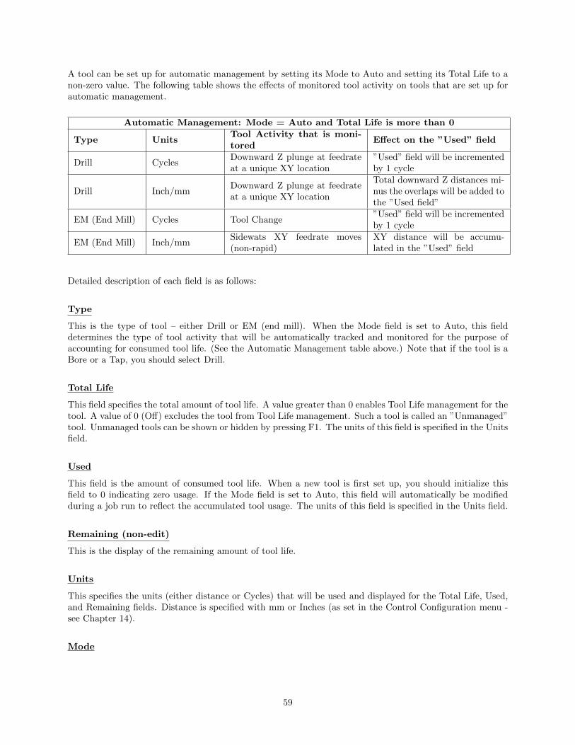
A tool can be set up for automatic management by setting its Mode to Auto and setting its Total Life to anon-zero value. The following table shows the effects of monitored tool activity on tools that are set up forautomatic management.
Automatic Management: Mode = Auto and Total Life is more than 0
Type UnitsTool Activity that is moni-tored
Effect on the ”Used” field
Drill CyclesDownward Z plunge at feedrateat a unique XY location
”Used” field will be incrementedby 1 cycle
Drill Inch/mmDownward Z plunge at feedrateat a unique XY location
Total downward Z distances mi-nus the overlaps will be added tothe ”Used field”
EM (End Mill) Cycles Tool Change”Used” field will be incrementedby 1 cycle
EM (End Mill) Inch/mmSidewats XY feedrate moves(non-rapid)
XY distance will be accumu-lated in the ”Used” field
Detailed description of each field is as follows:
Type
This is the type of tool – either Drill or EM (end mill). When the Mode field is set to Auto, this fielddetermines the type of tool activity that will be automatically tracked and monitored for the purpose ofaccounting for consumed tool life. (See the Automatic Management table above.) Note that if the tool is aBore or a Tap, you should select Drill.
Total Life
This field specifies the total amount of tool life. A value greater than 0 enables Tool Life management for thetool. A value of 0 (Off) excludes the tool from Tool Life management. Such a tool is called an ”Unmanaged”tool. Unmanaged tools can be shown or hidden by pressing F1. The units of this field is specified in the Unitsfield.
Used
This field is the amount of consumed tool life. When a new tool is first set up, you should initialize thisfield to 0 indicating zero usage. If the Mode field is set to Auto, this field will automatically be modifiedduring a job run to reflect the accumulated tool usage. The units of this field is specified in the Units field.
Remaining (non-edit)
This is the display of the remaining amount of tool life.
Units
This specifies the units (either distance or Cycles) that will be used and displayed for the Total Life, Used,and Remaining fields. Distance is specified with mm or Inches (as set in the Control Configuration menu -see Chapter 14).
Mode
59

This specifies the update mode of the Used field – either Auto or Manual. If this field is set to Auto, thentool activity is monitored during a job run for tool usage which will be automatically accumulated in theupdated Used field. (See the Automatic Management table above.) If this field is set to Manual, no suchautomatic updates will take place on the Used field. Rather, updates to the Used field will be dependentupon user variable modifications programmed in the G-code program being run. (See the section Tool LifeManagement - Using G-Code User Variables later in this chapter.)
Description
This field contains a text description of the tool. The description will appear in a prompt message on thescreen when the CNC software reaches a tool change (M6) during a job run.
5.3.1 Effect on Job Run and Backplot
At Start of Job
Tool life expiration will be checked at the beginning of a job run. If any managed tools are expired at thebeginning of a job, the following dialog will show up and you will have one of 3 choices to make:
When a job is first started, the CNC software will not yet know which tools are going to be used in the jobuntil the job is successfully completed. Therefore, the tools listed here will be the list of all expired toolseven if they are not going to be used in the job.
At Job Restart
Tool life expirations are also checked upon job restart (i.e. upon encountering M2 or M102). If any tool(s)expired during the previous job run (previous to the M2 or M102), then the dialog that is displayed is similarto that shown above except that the expired tools listed will only be the ones that were used in the job.
At End Of Job
When tool life expires during a job, such an event will not cancel the job. Instead, upon successful end ofthe job the following dialog will be displayed and you will have an opportunity to quickly get to the ToolLife Management menu:
This end-of-job dialogue will show only the expired tools that were used in the job.
60
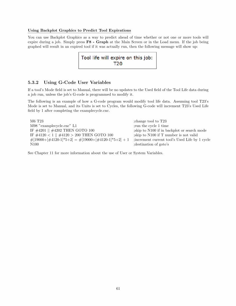
Using Backplot Graphics to Predict Tool Expirations
You can use Backplot Graphics as a way to predict ahead of time whether or not one or more tools willexpire during a job. Simply press F8 - Graph at the Main Screen or in the Load menu. If the job beinggraphed will result in an expired tool if it was actually run, then the following message will show up:
5.3.2 Using G-Code User Variables
If a tool’s Mode field is set to Manual, there will be no updates to the Used field of the Tool Life data duringa job run, unless the job’s G-code is programmed to modify it.
The following is an example of how a G-code program would modify tool life data. Assuming tool T23’sMode is set to Manual, and its Units is set to Cycles, the following G-code will increment T23’s Used Lifefield by 1 after completing the examplecycle.cnc.
M6 T23 ;change tool to T23M98 ”examplecycle.cnc” L1 ;run the cycle 1 timeIF #4201 || #4202 THEN GOTO 100 ;skip to N100 if in backplot or search modeIF #4120 < 1 || #4120 > 200 THEN GOTO 100 ;skip to N100 if T number is not valid#[19000+[#4120-1]*5+2] = #[19000+[#4120-1]*5+2] + 1 ;increment current tool’s Used Life by 1 cycleN100 ;destination of goto’s
See Chapter 11 for more information about the use of User or System Variables.
61
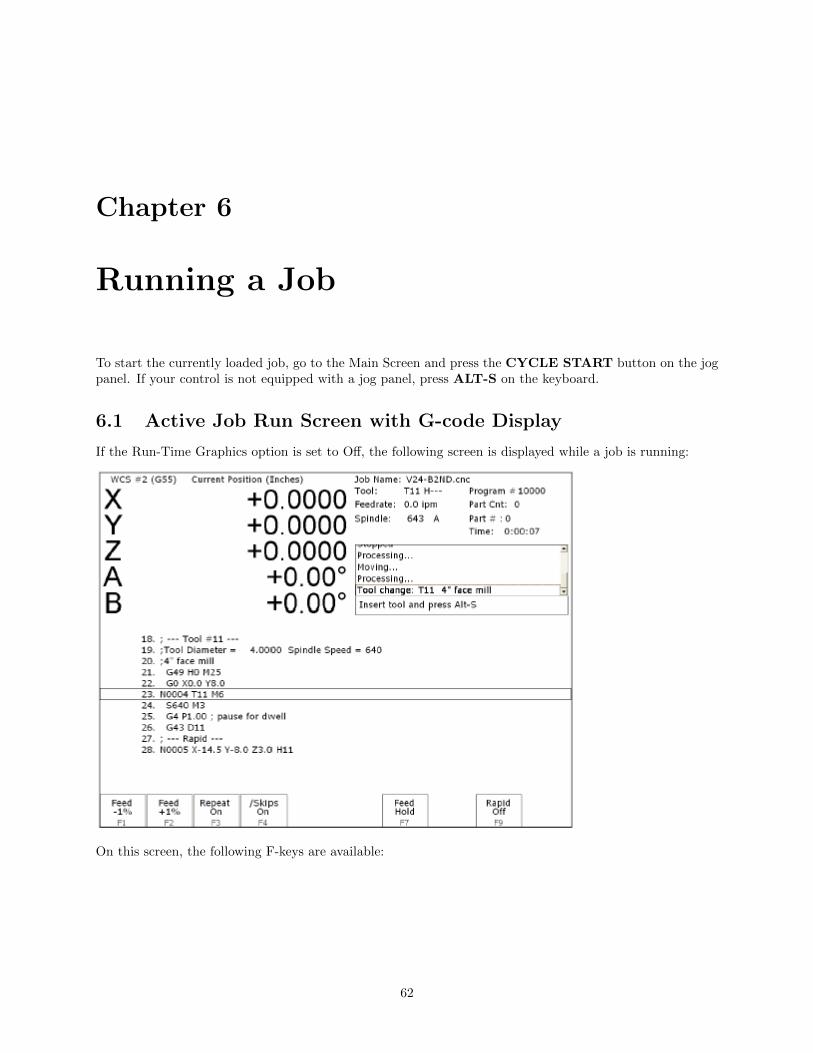
Chapter 6
Running a Job
To start the currently loaded job, go to the Main Screen and press the CYCLE START button on the jogpanel. If your control is not equipped with a jog panel, press ALT-S on the keyboard.
6.1 Active Job Run Screen with G-code Display
If the Run-Time Graphics option is set to Off, the following screen is displayed while a job is running:
On this screen, the following F-keys are available:
62

F1 -– Feed (-1% ) Decrease feedrate override by 1% . (Available only if keyboard jogging is active.)F2 -– Feed (+1% ) Increase feedrate override by 1% . (Available only if keyboard jogging is active.)
F3 -– Repeat On/Off Toggle the repeat feature for part counting. For more information, see F3 under theRun Menu section later in this chapter.
F4 -– Skips On/Off Enable/Disable block skips. For more information, see F4 under the Run Menu sectionlater in this chapter.
F5 -– Auto This key will only appear in Single Block mode. When you press this key, it turnson Auto mode and disables Single Block mode. Once Auto mode is turned on, SingleBlock cannot be re-enabled unless you stop the job. For more information, see F5under the Run Menu section later in this chapter.
F6 — Stops off This key will only appear if Optional Stops is on. When you press this key, it turns offOptional Stops. Once Optional Stops is turned off, it cannot be re-enabled unless youstop the job. For more information, see F6 under the Run Menu section later in thischapter.
F7 -– Feed Hold Turn feed hold on/off. (Available only if keyboard jogging is active.)F8 — Graph Switch to run-time graphics screen. This key only appears if the job was started with
the run-time graphics option turned on.F9 -– Rapid On/Off Turn rapid override on/off.
For information on other keys that are available while a job is running, see Chapter 2.
6.2 Run-Time Graphics Screen
When a job is running with Run-Time Graphics set to On, the following screen is displayed:
The following keys are available while the job is running in Run Time Graphics.
F7 -– Clear Clears the trail up to the tool’s current position in the program.F8 — G-Code Switch to the Job Run Screen with G-Code display.F9 -– Trail On/Off Turn on/off the tool trail display.
63
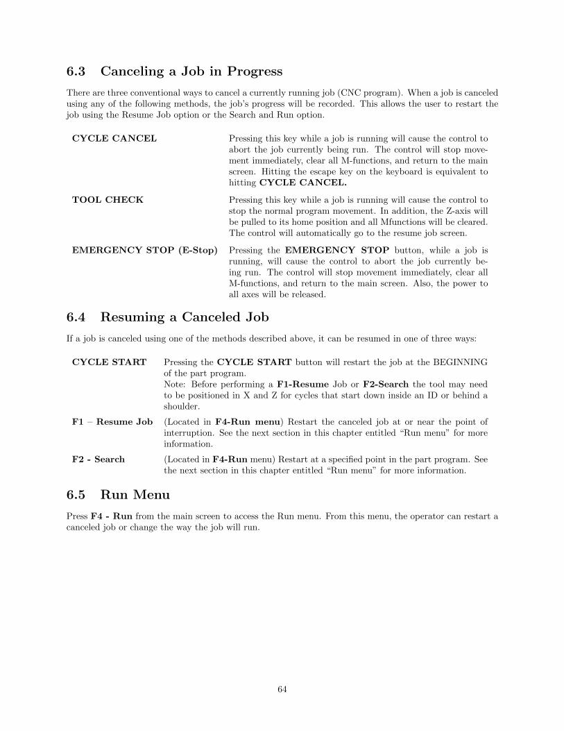
6.3 Canceling a Job in Progress
There are three conventional ways to cancel a currently running job (CNC program). When a job is canceledusing any of the following methods, the job’s progress will be recorded. This allows the user to restart thejob using the Resume Job option or the Search and Run option.
CYCLE CANCEL Pressing this key while a job is running will cause the control toabort the job currently being run. The control will stop move-ment immediately, clear all M-functions, and return to the mainscreen. Hitting the escape key on the keyboard is equivalent tohitting CYCLE CANCEL.
TOOL CHECK Pressing this key while a job is running will cause the control tostop the normal program movement. In addition, the Z-axis willbe pulled to its home position and all Mfunctions will be cleared.The control will automatically go to the resume job screen.
EMERGENCY STOP (E-Stop) Pressing the EMERGENCY STOP button, while a job isrunning, will cause the control to abort the job currently be-ing run. The control will stop movement immediately, clear allM-functions, and return to the main screen. Also, the power toall axes will be released.
6.4 Resuming a Canceled Job
If a job is canceled using one of the methods described above, it can be resumed in one of three ways:
CYCLE START Pressing the CYCLE START button will restart the job at the BEGINNINGof the part program.Note: Before performing a F1-Resume Job or F2-Search the tool may needto be positioned in X and Z for cycles that start down inside an ID or behind ashoulder.
F1 – Resume Job (Located in F4-Run menu) Restart the canceled job at or near the point ofinterruption. See the next section in this chapter entitled “Run menu” for moreinformation.
F2 - Search (Located in F4-Run menu) Restart at a specified point in the part program. Seethe next section in this chapter entitled “Run menu” for more information.
6.5 Run Menu
Press F4 - Run from the main screen to access the Run menu. From this menu, the operator can restart acanceled job or change the way the job will run.
64
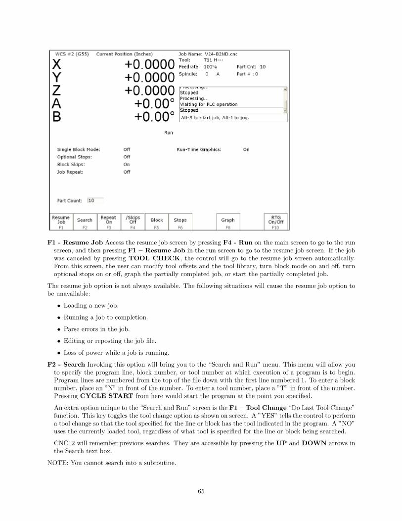
F1 - Resume Job Access the resume job screen by pressing F4 - Run on the main screen to go to the runscreen, and then pressing F1 – Resume Job in the run screen to go to the resume job screen. If the jobwas canceled by pressing TOOL CHECK, the control will go to the resume job screen automatically.From this screen, the user can modify tool offsets and the tool library, turn block mode on and off, turnoptional stops on or off, graph the partially completed job, or start the partially completed job.
The resume job option is not always available. The following situations will cause the resume job option tobe unavailable:
• Loading a new job.
• Running a job to completion.
• Parse errors in the job.
• Editing or reposting the job file.
• Loss of power while a job is running.
F2 - Search Invoking this option will bring you to the “Search and Run” menu. This menu will allow youto specify the program line, block number, or tool number at which execution of a program is to begin.Program lines are numbered from the top of the file down with the first line numbered 1. To enter a blocknumber, place an ”N” in front of the number. To enter a tool number, place a ”T” in front of the number.Pressing CYCLE START from here would start the program at the point you specified.
An extra option unique to the “Search and Run” screen is the F1 – Tool Change “Do Last Tool Change”function. This key toggles the tool change option as shown on screen. A ”YES” tells the control to performa tool change so that the tool specified for the line or block has the tool indicated in the program. A ”NO”uses the currently loaded tool, regardless of what tool is specified for the line or block being searched.
CNC12 will remember previous searches. They are accessible by pressing the UP and DOWN arrows inthe Search text box.
NOTE: You cannot search into a subroutine.
65

F3 – Repeat On/Off This key toggles the repeat feature for part counting. When part counting is ineffect and Repeat is on, the job will be automatically run again until the specified number of parts hasbeen run. The On or Off label indicates the state to which the repeat feature will toggle to when pressed.It does not indicate the current state. The current state is indicated in the user window above.
The Part Count: prompt is used to set the Part count. Positive values set the part counter to count upand negative values configure the part count to count down. For example, if 10 is entered in the Part Countprompt, the Part Cnt in the status window changes to 10 and the Part # changes to 0 with an upwardarrow indicator. When a job is run and then completes, the Part # will increment to 1. If repeat is on, thejob will automatically start again and keep running until the Part # has reached the Part Cnt. If a –10 isentered in the Part Count prompt, the Part Cnt in the status window changes to 10 and the Part # changesto 10 with a downward arrow indicator. When a job is finished, the Part # will decremented to 9. If repeatis on, the job will automatically start again and keep running until the Part # has reached 0.
F4 - Skips On/Off This function toggles the block skip feature. When block skipping is on, G-code linesthat start with a forward slash character ‘/’ are skipped, i.e., they are not processed. Note that becauseof the way a job is processed (in a pre-processed buffered fashion) the effect of this key may be delayedif you press it while a job is running. The On or Off label indicates the state to which the /Skips featurewill toggle to when pressed. It does not indicate the current state. The current state is indicated in theuser window above.
F5 - Block Mode Turns single block mode on and off. This is similar to pressing AUTO/BLOCK. IfSingle Block mode is on, the CNC software will stop after each block in your part program and wait foryou to press CYCLE START. Note that Auto mode is the default mode. If you use this key to turnon Single Block mode and then run a job, Auto mode will be re-instated when the job ends. The currentstate of this setting is indicated in the user window above.
F6 - Optional Stops Turns optional stops on and off. If optional stops are on, any M1 codes that appearin your program will cause a wait for CYCLE START (just like M0). If optional stops are off, M1 codeswill be ignored. Note that the default mode for Optional Stops is off. If you use this key to turn on SingleBlock mode and then run a job, Optional Stops will be set to off when the job ends. The current state ofthis setting is indicated in the user window above.
F8 — Graph Graphs the part. For more information, see the ”F8 - Graph” section in chapter 3. Ifthis feature is invoked from the Run and Search screen or the Resume Job screen, then the graphics willshow exactly where the searched line or block begins. Dotted lines indicate the portion of the part that isskipped. Solid lines indicate the portion of the part that will be machined.
F9 – Rapid On/Off This function key toggles Rapid Override. The On or Off label indicates the state towhich the Rapid Override feature will toggle when pressed. In the Rapid Override On state, the speed ofrapid moves (G0) can be adjusted by the Feedrate Override knob. In the Rapid Override Off state, thespeed of rapid moves will be at full speed (max rate).
F10 – RTG On/Off This function key toggles the Run-Time Graphics option. If the option is turned on,Run-Time Graphics automatically starts when the CYCLE START button is pressed. This option mustbe turned on for Run-Time Graphics to be used. If the option is turned off, Run- Time Graphics cannotbe started while a job is running.
Machine Parameter 400 determines whether or not CYCLE START is enabled on the Run Menu. Ifparameter 400 is set to zero, then CYCLE START is disabled in the Run Menu. For any other valueof parameter 400, CYCLE START is enabled. Note that this does not apply to the Resume and Searchsub-menus, where CYCLE START is always enabled.
6.6 Power Feed
Press F4 - Feed from the Setup menu to access the Power Feed screen. This screen is used to commandaxis movement. All the operations available on the Power Feed screen may also be performed in MDI with
66

the appropriate M and G codes.
F1 - Absolute Power Feed Press F1 - ABS to move an axis to an absolute position, at a specifiedfeedrate.
F2 - Incremental Power Feed Press F2 - INC to move an axis an incremental distance, at a specified
F3 - Free XY Press F3 - Free to release power to the X and Y motors, allowing you to use your machinemanually for these two axes. feedrate.
F4 - Power XY Press F4 - Power to apply power to the X and Y motors, allowing you o use your machinewith the jog panel for these two axes.
67

Chapter 7
The Utility Menu
To get to the Utility Menu, press F7 - Utility at the CNC software Main Screen. The model will varydepending on your M-Series Control model.
68

F2 - Restore Report This option is used primarily for restoring a system configuration from apreviously saved report.zip file (See F7 - Create Report).
F3 - Backup Files This creates an archive file ”cnc backup.zip” containing CNC program files,Intercon part program files, MillWrite engraving files, and digitized output files from the followingdirectories and their subdirectories: ncfiles directory, c:\intercon, c:\mw, and any other directoriesmentioned in the pathm.ini configuration file.
F4 - Restore Files Use this option to restore the data previously backed up with F3 - Backup Files.(Note that this feature will not work with backups created by control software prior to version 3.04.)
F5 - File Ops Use this menu to perform file and directory operations such as: Importing and Exporting(copying) files to and from the control, rename or delete files, create or delete directories.
F1 - Toggle Press once to select or press again to unselect a single file.F2 - All/None Press once to select all or press again to unselect all files.F3 - Import/Export Import or Export selected files.F4 - Edit Opens selected file in editor.F5 - Refresh Refresh file list. Use after inserting a new USB storage device.F7 - Rename Rename selected file or directory.F8 - New Dir Create a new directory in the current folder.F9 - Delete Deletes selected file or directory.Page Up Move the cursor backward one page.Page Down Move the cursor forward one page.End Select The last file in the list.Home Select The first file in the list.Arrow Keys Move the cursor in the selected direction.
F6 - User Maint Use this menu to perform user maintenance such as checking an axis for excessive
69

drag or setting backlash.
F1 - Drag The Drag Factor utility is used to determine if an axis has an excessive amount of drag.To run a drag test, use the F1 key to select the axis which you wish to test, position the axis at ornear the home position and press CYCLE START. The axis will move back to the home switchthen traverse the entire range of travel for the axis moving to the opposite limit and returning tohome while moving the slow jog rate. If excessive friction (drag) is encountered an error messagewill be displayed. When the test completes, use F8 - Graph to display the results. The redhorizontal lines indicate the bounds acceptable limits for the machine as it is currently configured.
F2 - Lash (Backlash Compensation) In order to insure an accurate measurement always set thebacklash compensation in the control to zero before attempting to measure the physical lash in anaxis.
F7 - Create Report Generates a backup of system configuration files called report.zip and copies it tothe specified location. Your dealer may then use this file for servicing and troubleshooting purposes. Torestore the configuration files from the report disk, press F2 - Restore Report from the Utility menu.
F8 - Options Shows the software options that you have purchased or added to your control. On thisscreen you can also enter unlock codes for software options that you have purchased. This page will alsodisplay the PLC programs, PIC type, and System ID #.
F9 - Logs Shows the messages and errors that have been logged by the control.
F1 - Errors Displays the error/message log. Use Page Up, Page Down, Home, and End toview and ESC to exit.
F2 - Stats Displays counts of errors logged. Use Page Up, Page Down, Home, and End toview and ESC to exit.
F3 - Export Exports the log to a destination of your choosing.
70
Chapter 8
Digitizing
The Digitize feature of the CNC software can be used to digitize surfaces in a variety of scenarios. Thedigitizing process creates a file with M & G-codes that represent the digitized surface. If the digitizingprobe tip is chosen to match the milling cutter size, the digitized file can be loaded and run to produce anexact copy of the digitized part.
F1 - Grid Digitize rectangular surface area.
F2 - Radial Digitize inside of a bore.
71

F3 - Contour Digitize inside or outside contour. (Not available if Parameter 155 is set to 2)
F4 - Probe Select from the Probing Cycles (See Chapter 9 of this manual).
F6 - Dig to CAD Export digitized files for use with a CAD/CAM system.
F8 - Wall Following Digitize inside and/or outside contour .
8.1 Grid Digitize (F1 from Digitize Menu)
Grid Digitize Run Setup
To set up a digitizing run, edit the parameters shown and then press CYCLE START. The control willmove through the area to be digitized in a rectangular pattern. At each X-Y point in the pattern, it willmeasure the Z height of the sample surface, and record the coordinates in the data file. Digitizing begins atthe current tool position when the CYCLE START button is pressed. This position should be in onecorner of the digitize area, at a Z position higher than any point on the surface.
Grid Digitize Parameters
Type: This sets the algorithm for digitizing: either regular Grid or Surface Following.
X Patch Length: The length of the area to be digitized, along the X-axis. A positive value will causedigitizing to proceed in the X+ direction from the starting point; a negative value will cause digitizing toproceed in the X direction. If the value is 0, then digitizing will collect just one stripe along Y.
72

X Step Over: The distance to move between points on the X-axis. A smaller value should be used for afine digitize along the X-axis. A larger value should be used for a rough digitize along the X-axis. Thisdistance should be a positive incremental value.
Y Patch Width: The width of the area to be digitized, along the Y-axis. A positive value will causedigitizing to proceed in the Y+ direction from the starting point; a negative value will cause digitizing toproceed in the Y direction. If the value is 0, then digitizing will collect just one stripe along X.
Y Step Over: The distance to move between points on the Y-axis. A smaller value should be used for afine digitize along the Y-axis. A larger value should be used for a rough digitize along the Y-axis. Thisdistance should be a positive incremental value.
Z Maximum Depth: The maximum distance the Z-axis moves below the starting height. If the probedoes not contact the surface at the maximum depth, that data point will be recorded as being at themaximum depth, and digitizing will proceed with the next point.
Z Step Up: The distance the Z-axis moves up after making contact, before the control attempts tomove X or Y. A small value should be used when digitizing parts with gentle slopes; a larger valueshould be used when digitizing parts with many steep walls.
Axis to Move First: The axis (either X or Y) which moves all the way across the digitize area witheach pass.
Digitize File Name: The base name of the output file in which the digitize data is stored. Anextension of .dig will automatically be appended to the name for replay as a CNC job.
Replay Feedrate: The feedrate to include with the G1 command on the first line of the data file. If thedata file is run as a CNC program, this is the feedrate at which the machine will retrace the digitizedsurface.
Multiple Patch: Indicates whether or not this digitizing is a continuation of an earlier digitizing.Choose NO if the current digitizing is the first or only digitize run for the part to be digitized. ChooseYES if the current digitizing is not the first digitize run for the part. If Yes is selected, specify the nameof a digitize file of a previous multiple patch.
Replay Pattern: Indicates the replay movement pattern. If ZIG ZAG is selected, the replay patternwill alternate between positive and negative directions on each successive pass. If ONE WAY is selected,the replay pattern will maintain a constant ”one-way” direction throughout the playback.
Probe Diameter: Indicates the probe tip diameter.
73

Grid Digitize Notes
1. A guide to the possible grid digitizing paths is as follows:
2. A digitizing patch can be located anywhere in the coordinate system. The digitizing starting point isreferenced from the part zero. For example, setting up digitizing, as shown in the figure on the rightbelow, will record the first point at (X5, Y5, Z1) and the last point at (X7, Y7, Z1). If the digitizingreplay starting point is desired to be at the part zero be sure to set the part zero equal to thedigitizing start point, as shown in the figure on the left below. This orientation will record the firstpoint at (X0, Y0, Z0) and the last point at (X2, Y2, Z1). For more information on part setup seeChapter 4.
74

3. A good technique for calculating Z maximum depth is to touch off the lowest surface of the part to bedigitized and set the part zero’s Z value to Z0. Then jog the probe tip to a point higher than thehighest surface of the part to be digitized. Note the displacement in the Z-axis. Again, set this Zheight to Z0 and use the noted displacement for the Z maximum depth.
4. Multiple patches are useful in the following situations: completing a canceled digitize run, digitizingparts with large areas that contain nothing to be digitized (shown below), and patching vertical wallsto eliminate scallops caused by the cutting tool.
The drill shown in the previous example is L-shaped. Therefore, it can be digitized faster and moreefficiently using three rectangular patches than digitizing the complete area with a single patch.
75

Digitizing the entire part and then adding multiple small patches along the walls can avoid vertical wallscalloping. If a vertical wall extending along the X axis needs to be cleared of scallops, just add a smallpatch running the length of the wall. Set the ”Axis to Move First” parameter to Y. This will clear thescallops.
8.2 Radial Digitize (F2 from Digitize Menu)
Setting up a Radial Digitize Run
To set up a digitize run, edit the parameters shown. Jog the probe tip to the starting height and to thecenter of the bore to be digitized. Then press F1 - Center to define the center position for digitizing. Thiscenter position will be used as the center of all radial digitizing runs until you leave the radial digitizemenu or redefine the center. If you are using a full angle, you can now press CYCLE START to begindigitizing. If you have specified partial angle, press F2 - Partial to define the partial angle (see setting thepartial angle section in this chapter). After defining the partial angle, pressing CYCLE START will startthe digitize run.
WARNING: The probe must be able to retreat to the center from any position on thedigitize surface. If the digitize surface contains features that do not allow for the probe toexit after entering, a probe crash may occur! See radial digitize note 2 later in this section.
76

Radial Digitize Parameters
Containment Radius: The maximum distance from the center position to look for a digitize datapoint. This parameter is used to contain the probe within a circle with this radius centered at the centerposition. If the probe does not contact the surface before reaching the maximum radius that data pointwill be recorded as being at the maximum radius, and digitizing will proceed with the next point.
Z Patch Depth: The depth of the patch to be digitized, along the Z-axis. A positive value will causedigitizing to proceed in the Z+ direction from the starting point; a negative value will cause digitizing toproceed in the Z direction.
Z Step: The distance to move between points on the Z-axis. A smaller value should be used for a finedigitize along the Z-axis. A larger value should be used for a rough digitize along the Z-axis. Thisdistance should be a positive incremental value.
Outer Stepover: The distance to move between points on one contour. A smaller value should be usedfor a fine digitize along any one contour. A larger value should be used for a rough digitize along any onecontour. This distance should be a positive incremental value.
Replay Pattern: Indicates the replay movement pattern. If Zigzag is selected, the replay pattern willalternate between positive and negative angle directions (CW and CCW) on each successive contour. IfCW or CCW is selected, the replay pattern will maintain a constant angle direction throughout theplayback.
Replay Feedrate: The feedrate to include with the G1 command on the first line of the data file. If thedata file is run as a CNC program, this is the feedrate at which the machine will retrace the digitizedsurface.
Digitize File Name: The base name of the file in which the digitize data is stored. The file has anextension of .dig for CNC replay.
Containment Angle: Indicates whether or not the digitizing is to follow a full circle or a partial sector.Choose Full if 0 to 360 degrees is desired. Choose Partial if some other angles are needed. These partialangles can then be changed later (see setting the Partial Digitizing Sector Setup section that follows).
Multiple Patch: Indicates whether or not this digitizing is a continuation of an earlier digitizing.Choose No if the current digitizing is the first or only digitize run for the part to be digitized. ChooseYes if the current digitizing is not the first digitize run for the part. If Yes is selected, specify the nameof a digitize file of a previous multiple patch.
Move Between Levels: This field is enabled only if Partial and CCW or CW option is selected. Itindicates the move between Z levels on replay of a partial sector radial digitize file. This move may nowbe done in three different ways: Clearance, which goes to the clearance height as in previous versions,Center, which goes to the digitizing center and then to the Z level of the next pass, and Direct, whichgoes directly to the starting point of the next pass.
Clearance Height: This field is enabled only if Partial, CCW or CW replay pattern, and ClearanceMove type option is selected. This distance indicates the clearance height needed to move the cutter fromthe end of one contour to the beginning of the next contour. This distance should be a positive value.
77

Radial Digitize Notes
1. A guide to possible radial digitizing paths is as follows:
2. When radial digitizing, make sure the probe can fully retract to the center position withoutobstructions. Observe the two parts below. The cross section on the left has no obstructions thatcould keep the probe from full retraction to the center position. The cross section on the right doesnot allow the digitizing to retract to the center in Area A. This area will cause a probe crash; singlepatch digitizing of parts such as this should be avoided. Use 2 or more patches to digitize the part onthe right (in this case, you could divide the part in half horizontally, and do each half separately).
78

Partial Digitizing Sector Setup
If you set the Radial Digitize Containment Angle to ”Partial” then you must set up the Digitizing Setupby pressing F2 - Partial from the CNC software Radial Digitize Screen.
The partial sector can be setup one of two methods:
1. One method is by editing the start and end angles directly. The start angle is referenced from zerodegrees and defines the beginning of the digitizing sector. The end angle is referenced from zerodegrees and defines the end of the digitizing sector.
2. The second method involves jogging the probe tip and touching off the digitize surface. By movingthe probe tip to positions on the digitizing surface, one can set the angles. To set the start angle, jogthe probe tip to the position on the digitizing surface where the digitizing is to begin and press F1 -Start to define this as the start angle.
*Notice: that the picture of the sector and the start angle’s value change to reflect these settings.To define the end angle, follow the procedure above but press F2 - End instead to set the end angle.
Regardless of the method used to define the start and end angles, pressing F10 - Save saves the anglesand exits back to the radial digitize menu. Pressing ESC will return to the radial digitize menu withoutmaking changes to the start and end angles.
79

8.3 Contour Digitize (F3 from Digitize Menu)
Contour Digitize Run Setup
To set up a digitizing run, jog the probe tip to the center of the part and hit F1 - Center to assign that asyour center point.
Select CAM for a true CAM shape contour, or Wall for irregular shapes for wall following. Enter the restof the parameters for the part and digitizing job as shown below.
Jog the probe to a starting point and press CYCLE START. The control will move the probe toward thecenter line in the +/- X direction until it comes into contact with the part. At each point of contact, the Xand Y coordinates will be recorded in the data file.
The probe will continue around the contour until it returns to the starting point to complete the cycle.Based on the starting point, and the first point of contact, the digitize software will determine if thecontour is internal or external.
Important note: When probing an external contour, make sure the probe comes in contact with part onthe first move. If it doesn’t, the software will compensate to the outside of the part as if it were an internalcontour causing your part to come out larger than you want it to be.
80
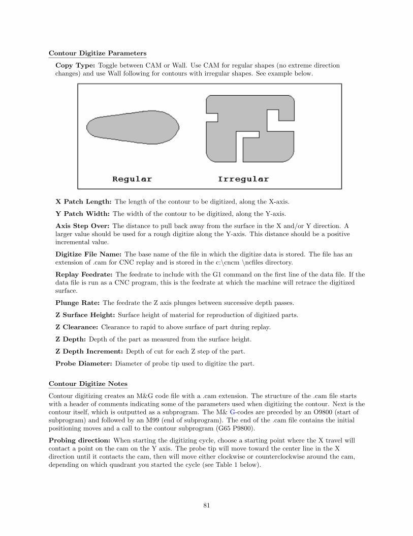
Contour Digitize Parameters
Copy Type: Toggle between CAM or Wall. Use CAM for regular shapes (no extreme directionchanges) and use Wall following for contours with irregular shapes. See example below.
X Patch Length: The length of the contour to be digitized, along the X-axis.
Y Patch Width: The width of the contour to be digitized, along the Y-axis.
Axis Step Over: The distance to pull back away from the surface in the X and/or Y direction. Alarger value should be used for a rough digitize along the Y-axis. This distance should be a positiveincremental value.
Digitize File Name: The base name of the file in which the digitize data is stored. The file has anextension of .cam for CNC replay and is stored in the c:\cncm \ncfiles directory.
Replay Feedrate: The feedrate to include with the G1 command on the first line of the data file. If thedata file is run as a CNC program, this is the feedrate at which the machine will retrace the digitizedsurface.
Plunge Rate: The feedrate the Z axis plunges between successive depth passes.
Z Surface Height: Surface height of material for reproduction of digitized parts.
Z Clearance: Clearance to rapid to above surface of part during replay.
Z Depth: Depth of the part as measured from the surface height.
Z Depth Increment: Depth of cut for each Z step of the part.
Probe Diameter: Diameter of probe tip used to digitize the part.
Contour Digitize Notes
Contour digitizing creates an M&G code file with a .cam extension. The structure of the .cam file startswith a header of comments indicating some of the parameters used when digitizing the contour. Next is thecontour itself, which is outputted as a subprogram. The M& G-codes are preceded by an O9800 (start ofsubprogram) and followed by an M99 (end of subprogram). The end of the .cam file contains the initialpositioning moves and a call to the contour subprogram (G65 P9800).
Probing direction: When starting the digitizing cycle, choose a starting point where the X travel willcontact a point on the cam on the Y axis. The probe tip will move toward the center line in the Xdirection until it contacts the cam, then will move either clockwise or counterclockwise around the cam,depending on which quadrant you started the cycle (see Table 1 below).
81

If the probe bypasses a contact point on the Y axis, it will continue moving in the X direction across thecenter line until it reaches the patch length limit and faults out.
Canceling a job: Unlike grid or radial digitizing if you cancel a contour operation before it is completedyou will not be able to restart the contour at the point of interruption to continue the cycle. You will needto start over.
Before running a job: Before running a job created by contour digitizing, you will need to add someinformation to the file to define any required tool change, cutter compensation and height offset commands.
1. Do a search in the G code for the phrase ”Add Comp Here.”
2. Refer to the descriptions of G40, G41 and G42 in Chapter 12.
3. Add the proper G code to the file after the ”Add Comp Here” prompt.
4. Save the file, and run your job.
82

8.4 Wall Following Digitizing (F8 from Digitize Menu)
Setting up a Wall Following Digitizing Run
To set up a digitize run, edit the parameters shown. Jog the probe tip to the XY starting location (insideor outside of the part to be digitized), and then jog Z to the level of the first digitize pass. Press CYCLESTART to start the digitize run.
Wall Following Digitizing Parameters
Probe Tool Number: The tool number of the probe.
Z Patch Distance: The total Z distance to digitize, incremental from the first pass. Entering anegative value will cause the routine to step down in the Z. Entering a positive value will cause theroutine to step up in the Z.
Z Step: The Z amount to step down per pass.
Stepover: The distance between the digitized points.
Digitize File Name: The base name of the output file in which the digitize data is stored. Anextension of .dig will automatically be appended to the name for replay as a CNC job.
Approach: The direction of the first digitizing move.
Inside/Outside: Starting location of the probe; inside the part or outside.
Cut Feedrate: The replay feedrate. This is the feedrate that will be output to the file specified by the
83

Digitize File Name above. This will cause the digitized data to be replayed at this specified feedratewhen the output data is run manual as a CNC job.
Cut Direction: The Clockwise or Counter Clockwise direction of the output data. This also defines thedirection of digitize.
Wall Following Digitizing Notes
The output data is uncompensated. Therefore the resultant output data points will be offset by the probetip’s radius amount. If you want to run this data as a CNC job and actually do cutting, you must use acutter that is the same shape and diameter as the probe tip. An alternative to this is to use a CAD/CAMsoftware package to remove the probe tip offset and to apply the desired compensation.
84

8.5 Dig to CAD (F6 from Digitize Menu)
The Dig to CAD feature of the CNC software is used to export digitized files for use with CAD/CAMsoftware. The digitized files are converted to point cloud data that is easily readable by most CAD/CAMsystems. Digitized files have either a .DIG or .DIG5 extension. Files with the extension .DIG are createdfrom the grid or wall following digitizing routines, while .DIG5 files are created from 5-axis digitizingtoolpaths. The resulting point cloud data files will have the same file name as the .DIG and .DIG5 filesthey were created from, only they will have a .TXT extension. These files can then be imported into anyCAD/CAM software or viewed with a simple text editor.
In the case of 5-axis CNC controls, where the 4th and 5th axes are rotary axes, parameters 116-119 areused in conjunction with Dig to CAD to properly position the collected data (see Chapter 14 for moreinformation on these parameters).
85

Converting Digitized Data
To export digitized data, first select the files you wish to convert by highlighting the files with the arrowkeys and using either F1 - Toggle or the Space bar to select the files. When a file has been selected anasterisk (*) will appear to the left of the file name. Once you have selected all the files you wish to convertpress F10 - Accept.
To convert the files and save them in the same directory as the digitized files press Y. To save the files in adifferent location such as a floppy or USB drive press N, navigate to the desired directory using the filemenu, and press F10 - Accept to convert and save the files in that location.
86

Chapter 9
Probing
Attention!! Refer to the Probe Parameters sections at the end of this chapter before usingany probe.
9.1 Part Setup with Probing
Single axis, single surface probing is available on the Set Part 0/Position screen using the F4 - Auto key.This allows you to probe various surfaces to define the part coordinate system. Multi-axis andmulti-surface probing cycles are available on a separate screen, accessible from Set Part 0/Position with theF5 - Probe key or from F4 - Probe in the digitize screen. These allow you to locate the center pointsand corners of differently shaped parts.
Brushless motor note: If you experience excessive vibration on a brushless drive system, use Parameter10 to select smooth deceleration in probing moves. See Chapter 14 for more information.
87

WARNING: Before manually jogging any probe, make sure the machine Feedrate is slow(less than 10 in/min) or damage to the probe may result!
Automatically Setting Part 0
Part zero can be found using the probe. Make sure your probe height and diameter offsets are set for thetool number you assigned to the probe and that parameter 12 is set to that tool number. The Edge FinderDiameter will be set automatically.
To set part 0 using the probe:
1. Select the current work coordinate system by pressing F6 - Prev WCS or F7 - Next WCS. Thenselect the axis you want to probe by pressing F1 - Next Axis.
2. Manually jog the probe about 1/2 inches away from the surface you wish to define. Make sure theapproach direction to the part is set properly. Probe the selected axis by pressing F4 - Auto. Whenthe surface is found, the control will assume this point to be the new axis 0.
3. If you want this probed surface to be something different than 0, enter the value by the using arrowkeys to highlight Part Position, and then type in the value and press F10 - Set.
Repeat steps 1-3 to set the remaining axes using the probe. Any previously entered Edge Finder Diameteror Tool Number value will be discarded.
Finding Center/Corner Points
To enter the Probing Cycles screen, press F5 - Probe from the Set Part 0/Position screen. You can locatethe center of a bore, boss, slot, or web. You can also find an inside corner, outside corner, or a single axis.The corner points don’t even have to be right angles! The Edge Finder Diameter doesn’t need to beentered since these cycles place the probe directly over the center or corner of the part.
9.2 Calibrating the Probe Tip Diameter
You can calibrate the probe tip diameter to compensate for pre-travel (the amount that the probe deflectsbefore it actually trips). Simply enter a probe tip diameter of zero, probe out a precision bore with aknown diameter, and enter the difference between the reported bore diameter and the found bore diameteras the actual probe tip diameter.
88

9.3 Probing Cycles
You can enter the Probing Cycles screen from either the Set Part 0/Position screen (F5 - Probe) or theDigitize menu (F4 - Probe). The Probing Cycles screen is shown below:
The probing cycles will report the location and dimensions, as applicable, of the probed feature in afloating dialog box. The dimensions are adjusted to compensate for the probe tip diameter, entered in theOffset Library (see Parameter 12). For your convenience, you can edit the probe diameter on this screen,as long as the Tool Number, as set in Parameter 12, is not 0. During the probing cycles, the probe willmove at speeds specified in Parameters 14 and 15. Refer to the Probe Parameters section later in thischapter for more information.
89

F1 – Bore Press to enter the Bore screen. A picture similar to the one shown at right will appear, withinstructions. Follow these steps:
1. Make sure the probe is clear of any obstacles.
2. Manually jog the probe inside the hole. The probe tip should be just below the top edge of thesurface.
3. Press CYCLE START to start the probing.
At the end of probing, the probe will be positioned at the center of the bore, and the X and Y positionswill be shown on the screen.
Press ESC to return to the Set Part 0/Position screen or digitize screen.
F2 - Boss Press to enter the Boss screen. A picture similar to the following will appear, withinstructions and two input fields. Follow these steps:
1. Press F1 - Orient to select the orientation of the probe with respect to the Boss. You will see oneof the screens shown below.
2. Slowly jog the probe to the approximate orientation as shown in the picture. Be sure to give enoughspace for the probe tip to clear any obstacles during the jog.
3. Enter the approximate Boss diameter.
4. Highlight the Z clearance amount by pressing the down arrow key. Enter approximate distance (inthe Z direction) the probe must move to lift up over the Boss.
5. Press CYCLE START to start the probing cycle.
If the Z clearance you entered is too small, the probe will stop and show an error message. Correct theproblem by repeating the previous steps. If the approximate diameter you entered is too small, the probewill bounce by 10 percent of its diameter across the top surface until it either finds the correct edge, theadditional distance searched is equal to Parameter 16, or a travel limit is reached.
Once the probing cycle is complete, the probe will be positioned at the center of the boss at the Zclearance level entered. Press ESC to return to the Set Part 0/ Position screen or digitize screen.
90

F3 - Slot Press to enter the Slot screen. A picture similar to the ones shown will appear along withinstructions:
1. Press F1 - Orient to select the orientation of the probe with respect to the slot.
2. Slowly jog the probe to the approximate position shown in the picture. During this jog, make sureyou have enough space between the probe and the part.
3. Press CYCLE START to begin probing.
Once the cycle is finished, the probe will belocated at the center of the slot. Press ESC to return to the Set Part 0 – Position Screen or digitize screen.
F4 - Web Press to enter the Web screen. A picture similar to the following will appear, withinstructions and two input fields. Follow these steps:
1. Press F1 - Orient to select the orientation of the probe. You will see one of the screens shownbelow.
2. Slowly jog the probe to the approximate position shown in the picture. During this jog, be sure togive enough space between the probe and the part.
3. Enter the approximate Web width.
4. Highlight the Z clearance value using the up or down arrow key. Enter approximate distance theprobe has to travel in order to lift up over the Web.
5. Press CYCLE START to start the probing cycle. Once the probe has completed its search, it willautomatically position to the centerline of the web.
If the Z clearance you entered is too small, the probe will stop and show an error message. Correct theproblem by repeating the previous steps. If the approximate width you entered is too small, the probewill bounce by 10 percent of its width across the top surface until it either finds the correct edge, theadditional distance searched is equal to Parameter 16, or a travel limit is reached.
Once the probing cycle is complete, the probe will be positioned at the center of the web, at the Zclearance level entered. Press ESC to return to the Set Part 0/ Position screen or digitize screen.
91
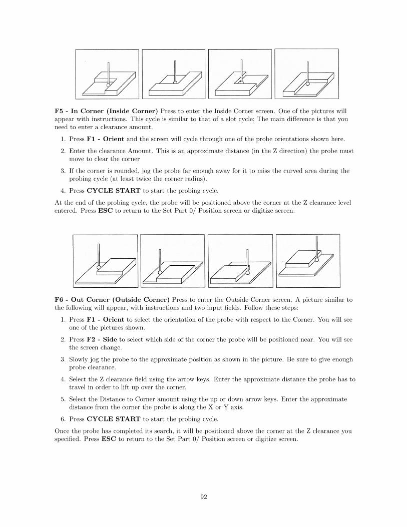
F5 - In Corner (Inside Corner) Press to enter the Inside Corner screen. One of the pictures willappear with instructions. This cycle is similar to that of a slot cycle; The main difference is that youneed to enter a clearance amount.
1. Press F1 - Orient and the screen will cycle through one of the probe orientations shown here.
2. Enter the clearance Amount. This is an approximate distance (in the Z direction) the probe mustmove to clear the corner
3. If the corner is rounded, jog the probe far enough away for it to miss the curved area during theprobing cycle (at least twice the corner radius).
4. Press CYCLE START to start the probing cycle.
At the end of the probing cycle, the probe will be positioned above the corner at the Z clearance levelentered. Press ESC to return to the Set Part 0/ Position screen or digitize screen.
F6 - Out Corner (Outside Corner) Press to enter the Outside Corner screen. A picture similar tothe following will appear, with instructions and two input fields. Follow these steps:
1. Press F1 - Orient to select the orientation of the probe with respect to the Corner. You will seeone of the pictures shown.
2. Press F2 - Side to select which side of the corner the probe will be positioned near. You will seethe screen change.
3. Slowly jog the probe to the approximate position as shown in the picture. Be sure to give enoughprobe clearance.
4. Select the Z clearance field using the arrow keys. Enter the approximate distance the probe has totravel in order to lift up over the corner.
5. Select the Distance to Corner amount using the up or down arrow keys. Enter the approximatedistance from the corner the probe is along the X or Y axis.
6. Press CYCLE START to start the probing cycle.
Once the probe has completed its search, it will be positioned above the corner at the Z clearance youspecified. Press ESC to return to the Set Part 0/ Position screen or digitize screen.
92

F7 - 1 Axis (Single Axis) Press to enter the Single Axis screen. Follow these steps:
1. Press F1 - Orient to select the orientation of the probe. You will see one of the screens shownbelow.
2. Slowly jog the probe to the approximate position as shown in the picture. Be sure to give enoughprobe clearance.
3. Press CYCLE START to start the probing cycle.
Once the probing cycle is complete, the probe will move away from the surface by the amount inParameter 13. The probedposition will be shown on screen. Press ESC to return to the Set Part 0/ Position screen or digitize screen.
F8 - Angle – Use this feature to measure an angle from based on 2 probed points. Follow these steps:
1. Press F1 - Orient to select how the angle is to be measured.
2. Slowly jog the probe to the first position as shown in the picture. Be sure to give enough probeclearance.
3. Select Auto or Jog between points.
4. Enter the distance to second point.
5. Enter a clearance amount away from the surface.
6. Press CYCLE START to start the probing cycle.
93

9.4 Probe / TT-1 Parameters
Various probing parameters can be set on the Machine Parameters screen (see Chapter 14). Make sure youenter these parameters before you begin using the probe and/or TT-1. If these parameters are not enteredproperly, damage to the probe or TT-1 may result.
Probe Type (Parameter 155): This specifies the probe type being used. This needs to be set to 0 ifyou are using a standard Mechanical probe.
Probe PLC Input Number and Contact State (Parameter 11): A single value, +/-1 through240. A positive number indicates Closed on contact; a negative number indicates Open on contact.
TT1 PLC input number (Parameter 44): This parameter is the input number that the TT1 iswired into on the PLC. If a shared PLC input is used for both the TT1 and the probe, then the valuecan be left at zero or set to the same value as parameter 11.
Probe Tool Number (Parameter 12): A single value, 0 through 200, used to look up the lengthoffset and tip diameter of the probe in the Offset Library.
Recovery Distance* (Parameter 13): The additional distance the probe moves off of a surface aftercontact is broken, before attempting to traverse parallel to the surface.
Fast Probing Rate* (Parameter 14): Used for positioning moves and initial surface detection, thisparameter is determined by machine response and permitted probe deflection as well as desiredtolerance. The default setting is 25 inches/min.
Slow Probing Rate* (Parameter 15): Used for final measuring moves, this parameter is determinedby a speed/accuracy tradeoff. The default setting is 3.5 inches/min.
Maximum Probing Distance (Parameter 16): The maximum distance that a probing cycle”searches” for a surface in a given direction if no travel limits have been entered. The default is 10 inches.A larger value should be entered for the hole and slot cycles if you are measuring very large features.
Detector Location Return Point (Parameter 17): A Zero (0) indicates that tool measurement willtake place at the current position, a 1 or 2 indicates the number of the G30 reference point to use whichspecifies the X, Y location of the TT1 (WCS Configuration).
*Mechanical type probe only. Please see the DSP type probe section below for differences.
94

9.5 DSP Probe Parameters
When using a DSP type probe (such as DP-7), a few of the probing parameters have a slightly differentbehavior than described above. These differences are noted below:
Probe Type (Parameter 155): This specifies the probe type being used. This needs to be set to 1 fora DP-4D probe or set to 2 for a DP-7 probe.
Repeatability tolerance for probing and radial digitizing (Parameter 151): used for DP-4probes. Must be set to 0 for DSP probes.
Grid digitize prediction minimum Z pullback (Parameter 121): set to 0.035 for DSP use.
Recovery Distance (Parameter 13): Works as described above but additionally it used as thedistance to retract for a retry after a failed window (does not apply to M115/116/125/126 moves)(Default for DSP is 0.05). Note: If probing small bores this parameter may need to be reducedaccordingly.
Fast Probing Rate (Parameter 14): When using a DSP type probe, this is actually the rate atwhich the probe will move ”in-between” actual probing moves. For instance, if you were probing a boss,this is the rate at which the probe will travel for the following moves:
1. When retracting from the surface after a point has been probed.
2. When retracting to the Z clearance position.
3. Rate at which it will traverse across the diameter of the boss at the Z clearance height.
4. Plunge rate to get to probing depth.
Note: When measuring a TOOL with the TT1, the behavior is identical to that listed above.
Slow Probing Rate (Parameter 15): Used only when measuring a TOOL with the TT-1.
9.6 Additional Probe Parameters for DP-7
For the DP-7 probe (parameter 155 = 2), the following additional parameters are utilized:
DP-7 Pullback Distance (Parameter 392): This sets the distance the probe moves off from thesurface after a probing move.
DP-7 Pullback Feedrate (Parameter 393): This sets the feedrate for the pullback move.
DP-7 Measuring Feedrate (Parameter 394): This sets the feedrate for the slow measuring move.
9.7 Probe Protection
Parameter 153 specifies whether the Probe Protection feature is enabled. When probe protection isenabled, most G-code, jog panel, and mpg moves will be stopped when the probe makes an unexpectedcontact. Unexpected contact is defined to be any probe contact made while jogging, using the mpg, ordoing a G-code move that is not a probing move (moves like M115 are probing moves and thus areexcluded from this definition).
9.7.1 Jog Panel Probe Protection
With proper PLC support, the jog panel includes probe protection. When jogging with a probe in, motionwill come to a stop if the probe is tripped. In this case, to clear the tripped probe, you may jog only in theopposite direction from which you were moving when you tripped the probe. For example, if you werejogging in the X+ direction when the probe tripped, you may only jog in the X- direction to clear the probe.NOTE: Proper PLC support is required for this feature to work!
95

9.7.2 Jog Parameters Menu for Probe Protection
In the jog parameters menu you may press F8 to go to the Probe Jog Parameters Menu. In this menu youmay set the slow and fast jog speeds that the machine will travel in when a probe is plugged in. Note thatfor fast jog, you can set the minus and plus directional jog speeds independently (for example, if you wantZ- to move especially slowly when a probe is plugged in). See the picture below for a still image from theprobe jog menu.
9.7.3 MPG Probe Protection
When probe protection is enabled, tripping the probe will cause MPG motion to stop for MPG withincrement multiplier set to 10x or 100x. To clear the probe you must set the increment multiplier to 1x
and then you can move the MPG in any direction on any axis.
9.7.4 Probe Protection While a Job is Running
If probe protection is enabled and the probe trips unexpectedly while a job is running, motion will stopand you may use the jog panel to clear the probe trip. These moves will also be stopped if the trip happensduring an MDI move.
96
Chapter 10
Intercon Software
10.1 Introduction
Intercon (Interactive Conversational) software allows you to quickly create a part program right at thecontrol without having to be a G-code expert. Intercon will prompt you to enter values from your printthat describes the geometry of the part. Intercon will display graphics of the part as you are creating it,helping you quickly proceed through part programming. Intercon can then generate a G-code program fromthe geometric information you have entered.
You can purchase an offline version of the Intercon software for use on your desktop PC. You will need topurchase a hardware key, which will allow the offline version to run. Simply plug the key into the computer,install the required drivers, and run it.
10.2 Intercon Main Screen
When you access Intercon through the F5 - CAM option in the CNC software Main screen, the partprogram will be displayed if the current job loaded in CNC software had an associated Intercon program. Ifthe job file in the CNC software did not have an associated Intercon program, the F1 - File menu will bedisplayed to load or create a file.
97

When the part program is displayed, different operations can be navigated and highlighted for additionalactions by using the arrow keys, and the HOME, END, PAGE UP and PAGE DOWN keys.
10.3 File Menu (Intercon Main Screen → F1 -– File)
F1 – File: Choosing F1 - File will display the screen below. Intercon stores part programs with anextension of .icn. For example, if you choose to name your new part program flange, Intercon will save theprogram as flange.icn. ICN files are only readable by Intercon.
F1 – File→ F1 – New: To program a new part, choose F1 – New. A prompt will be displayed where the
98
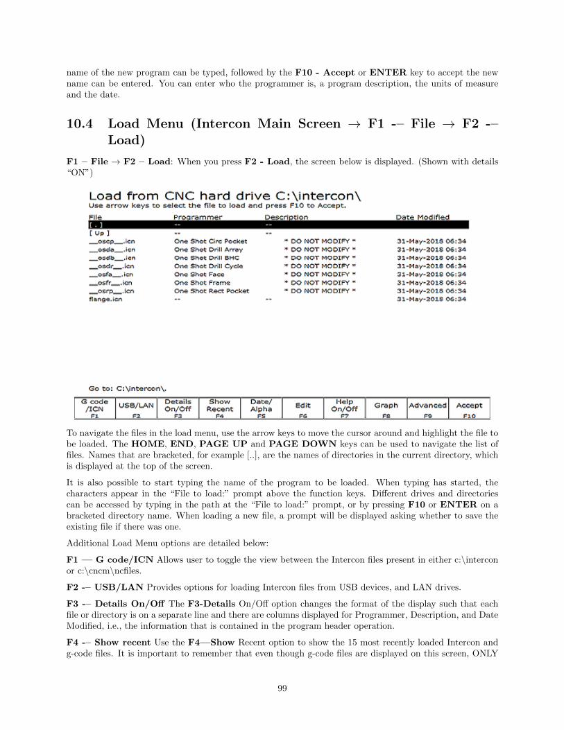
name of the new program can be typed, followed by the F10 - Accept or ENTER key to accept the newname can be entered. You can enter who the programmer is, a program description, the units of measureand the date.
10.4 Load Menu (Intercon Main Screen → F1 -– File → F2 -–Load)
F1 – File → F2 – Load: When you press F2 - Load, the screen below is displayed. (Shown with details“ON”)
To navigate the files in the load menu, use the arrow keys to move the cursor around and highlight the file tobe loaded. The HOME, END, PAGE UP and PAGE DOWN keys can be used to navigate the list offiles. Names that are bracketed, for example [..], are the names of directories in the current directory, whichis displayed at the top of the screen.
It is also possible to start typing the name of the program to be loaded. When typing has started, thecharacters appear in the “File to load:” prompt above the function keys. Different drives and directoriescan be accessed by typing in the path at the “File to load:” prompt, or by pressing F10 or ENTER on abracketed directory name. When loading a new file, a prompt will be displayed asking whether to save theexisting file if there was one.
Additional Load Menu options are detailed below:
F1 — G code/ICN Allows user to toggle the view between the Intercon files present in either c:\interconor c:\cncm\ncfiles.
F2 -– USB/LAN Provides options for loading Intercon files from USB devices, and LAN drives.
F3 -– Details On/Off The F3-Details On/Off option changes the format of the display such that eachfile or directory is on a separate line and there are columns displayed for Programmer, Description, and DateModified, i.e., the information that is contained in the program header operation.
F4 -– Show recent Use the F4—Show Recent option to show the 15 most recently loaded Intercon andg-code files. It is important to remember that even though g-code files are displayed on this screen, ONLY
99

Intercon files should be loaded from this screen. WARNING!!! Attempting to load a g-code file from the“Show Recent” screen will cause an error which will discard the current Intercon program. All unsavedchanges will be lost. If you should accidently load a g-code file, press escape to return to the main Interconmenu.
F5 -– Date/Alpha Use F5-Date/Alpha to view files either alphabetically or by date modified. By default,programs are listed in ascending alphabetical order.
F6 -– Edit Opens the selected file in Intercon for editing.
F7 -– Help On/Off Displays on screen help for the load menus.
F8 -– Graph Graphs the selected file.
F9 -– Advanced Displays file menu in a comprehensive “all in one” format similar to Windows Explorer
10.5 File Menu Continued
F1 -– File → F3 -– Save: Press F3 – Save to save the current part program. The current program willbe saved under the specified name.
F1 -– File→ F4 – Save As Press F4 -– Save As to save the current program with a different name. Typethe new name into the “Save part as:” prompt that appears above the function keys. If the new namealready exists, a prompt will be displayed as a warning and will give the option to overwrite the existing fileor return to enter a different name.
F1 -– File → F5 — Delete: Press F5 – Delete to delete a file. After F5 – Delete is pressed, the screenwill appear as in the F2 – Load option where you can be to navigate the files. A yes/no prompt will appearafter accepting a file for deletion for final confirmation.
F1 -– File→ F9 – Details on/off The F9 - Details On/Off changes the format of the display such thateach file or directory is on a separate line and there are columns displayed for Programmer, Description, andDate Modified, i.e., the information that is contained in the program header operation.
10.6 Intercon Main Screen Continued
F2 -– Modify: Choosing F2 - Modify (or press the ENTER key) from the Intercon main menu willallow the currently highlighted operation to be modified. When an operation is modified, the fields for thatoperation are displayed on the right hand side. When modifying an operation, the PAGE UP and PAGEDOWN keys can be used to move up and down through the Intercon operations listed on the left hand sideof the screen. See the ”Insert Operation” section later in this chapter for a description of each operationtype.
F3 -– Insert Choosing F3 – Insert will insert a new operation before the operation that is currentlyhighlighted, unless the highlighted operation is the first operation in which case the inserted operation willbe inserted as the second operation. For more information on the operations see Insert Operations later inthis chapter.
F4 -– Cut Choosing F4 – Cut will cut (remove) the highlighted operation from the program. The operationthat is cut is placed onto the clipboard stack.
F5 -– Paste Choosing F5 – Paste will paste the last operation that was cut or copied into the clipboardstack into the current program line that is before the highlighted operation. The number of operations thatare currently in the clipboard stack are indicated by the number in the Paste key. As long as you stay inIntercon, the clipboard stack will remain intact. You may cut and copy operations from one program andpaste them into a different program.
F6 -– Copy Choosing F6 – Copy will copy the highlighted operation into the clipboard stack and advancethe cursor to the next operation.
100
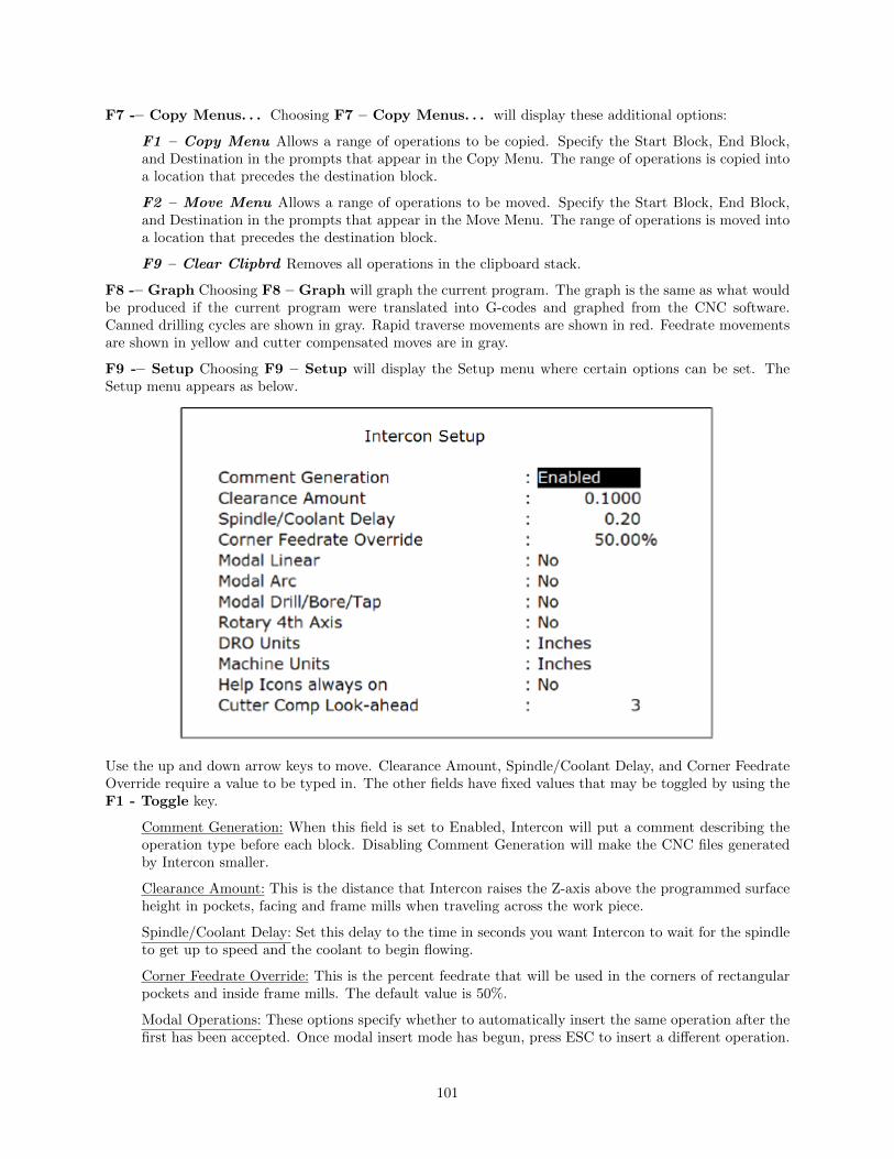
F7 -– Copy Menus. . . Choosing F7 – Copy Menus. . . will display these additional options:
F1 – Copy Menu Allows a range of operations to be copied. Specify the Start Block, End Block,and Destination in the prompts that appear in the Copy Menu. The range of operations is copied intoa location that precedes the destination block.
F2 – Move Menu Allows a range of operations to be moved. Specify the Start Block, End Block,and Destination in the prompts that appear in the Move Menu. The range of operations is moved intoa location that precedes the destination block.
F9 – Clear Clipbrd Removes all operations in the clipboard stack.
F8 -– Graph Choosing F8 – Graph will graph the current program. The graph is the same as what wouldbe produced if the current program were translated into G-codes and graphed from the CNC software.Canned drilling cycles are shown in gray. Rapid traverse movements are shown in red. Feedrate movementsare shown in yellow and cutter compensated moves are in gray.
F9 -– Setup Choosing F9 – Setup will display the Setup menu where certain options can be set. TheSetup menu appears as below.
Use the up and down arrow keys to move. Clearance Amount, Spindle/Coolant Delay, and Corner FeedrateOverride require a value to be typed in. The other fields have fixed values that may be toggled by using theF1 - Toggle key.
Comment Generation: When this field is set to Enabled, Intercon will put a comment describing theoperation type before each block. Disabling Comment Generation will make the CNC files generatedby Intercon smaller.
Clearance Amount: This is the distance that Intercon raises the Z-axis above the programmed surfaceheight in pockets, facing and frame mills when traveling across the work piece.
Spindle/Coolant Delay: Set this delay to the time in seconds you want Intercon to wait for the spindleto get up to speed and the coolant to begin flowing.
Corner Feedrate Override: This is the percent feedrate that will be used in the corners of rectangularpockets and inside frame mills. The default value is 50%.
Modal Operations: These options specify whether to automatically insert the same operation after thefirst has been accepted. Once modal insert mode has begun, press ESC to insert a different operation.
101

Rotary 4th Axis: This option specifies whether or not 4th axis movement fields appear in Linear andRapid moves and whether or not the Intercon program will post 4th axis movement. This option affectsthe value in the 4th axis configuration only (parameter 94). Note that although Intercon is restrictedto working with 1 rotary axis at a time, it can be directed to utilize the 5th axis as its rotary axisinstead of the 4th. To make Intercon to utilize the 5th axis as its rotary axis instead of the 4th axis,the 4th axis configuration (parameter 94) must have its rotary property turned off (bit 0 = 0) andthe 5th axis configuration (parameter 166) must have its rotary property turned on (bit 0 = 1). Seechapter 14 for details about parameters 94 and 166.
DRO Units: Specifies the Units used for the DRO. It affects the corresponding field in the ControlConfiguration.
Machine Units: Specifies the Units used for machining. It affects the corresponding field in the ControlConfiguration of the CNC software. The posted G-code will contain a G20 for Inches mode and a G21for Metric mode.
Help Icons always on: Toggle between yes or no. Selecting “yes” means that help information willalways be displayed when editing operations. “No” means that you will have to press a key to gethelp. Whether set to “yes” or “no”, the help screens can always be toggled on or off by pressing theF5 - Help key when editing an operation.
Cutter Comp Look-ahead: This sets the number of segments that can be parsed ahead when CutterComp is turned on.
F10 -– Post: Choosing F10 – Post will post the current program. Posting is the process of converting theoperations into G-codes. When the posting process is completed, Intercon is exited. The Intercon programis also saved as part of the posting.
10.7 Insert Operation (Intercon Main Screen → F3 – Insert)
When you press F3 – Insert, or when you choose New Part from the Main Screen, you will see the Insertscreen:
102

The new operation will be inserted right before the currently highlighted one. The operation types that youcan insert are listed across the bottom of the screen.
10.7.1 F1 – Rapid Traverse
Press F1 – Rapid from the Insert Operation screen to insert a Rapid Traverse. You may see the followingscreen:
103

End: When you first access the rapid traverse screen, the cursor will be highlighting the first field, EndX. This is the X coordinate of where the cutter will be after the rapid traverse has been completed.Similarly, Y and Z represent the coordinates of the cutter after the rapid traverse is completed. Theangle and length fields will be computed if you choose to enter the end point of the move.
Angle: The destination may also be specified in terms of a counterclockwise angle from the three o’clockposition. When combined with a length for the current move, the corresponding X and Y coordinatesfor the destination will be calculated and placed in the correct fields. The Z destination will remainunchanged, however.
Length: The length of the rapid traversal. When combined with the angle of the current move, thecorresponding X and Y coordinates for the destination will be calculated and placed in the correctfields. The Z destination will remain unchanged, however.
The F1 -– Abs/Inc key toggles between incremental and absolute positioning modes in any of the fieldswhere a positional dimension is needed. For example: X, Y, or Z-axis dimensions can all be in incrementalor absolute coordinates, or a mixture of both. The length and angle fields cannot be incremental. Thesefields are absolute values.
The F2 – Z Home key may be used on the Z destination field to tie the ending Z coordinate to the Z homeposition. This means that no matter what you’re Z home value is at the time that you run your program,the final Z position will be the Z home position.
When you are finished entering all of the dimensions for the rapid move, press F10 – Accept to accept theoperation and return to the Insert Operation screen.
NOTE: When making rapid moves, if a Z destination higher than the current cutter position isspecified, the cutter will first be raised to the destination Z position, and then move linearly inX and Y to arrive at the destination. If a Z destination lower than the current cutter positionis specified, the cutter will move linearly in X and Y first and then plunge Z to the destinationZ position.
NOTE: The Rapid traverse operation can have rotary fields, if you have a rotary fourth axis.
104

The rotary field descriptions are the same as that of the Linear Mill operation.
10.7.2 Linear Mill
If you press F2 - Linear from the Insert Operation screen, the following screen appears:
The numbers in the different fields on the screen correspond to the following Linear Mill example shown heregraphically:
End: When you first access the linear mill screen, the cursor will be highlighting the first field, EndX. This is the X coordinate of where the cutter will be after the linear move has been completed.Similarly, Y and Z represent the coordinates of the cutter after the linear move is completed. Theangle and length fields will be computed if you choose to enter the end point of the move.
Angle: The destination may also be specified in terms of a counterclockwise angle from the three o’clockposition. When combined with a length for the current move, the corresponding X and Y coordinates
105

for the destination will be calculated and placed in the correct fields. The Z destination will remainunchanged, however.
Length: The length of the linear mill. When combined with the angle of the current move, the corre-sponding X and Y coordinates for the destination will be calculated and placed in the correct fields.The Z destination will remain unchanged, however.
Connect Radius: If you are performing two linear mill operations and you wish to have a rounded’corner’ between them instead of a sharp peak, you may enter the radius of the ’corner’ and Interconwill insert an arc between the linear mill operations. This connect radius also works for blending a lineinto an arc operation.
Feedrate: Speed at which the cutter moves. The feedrate can be toggled to modal, fixed, or slave. Thisis indicated by the symbol beside the feedrate field. If the feedrate is modal then it will have the “M”symbol or if it is fixed it will have the “F” symbol shown below. The slave feedrate has no symbol andis set to the last modal feedrate set in the program, when the modal feedrate changes all the followingslave feedrates change until the next modal feedrate is encountered.
If you have a fourth axis installed and it is rotary, additional fields are shown for Linear Mill operationsafter the feedrate field.
Degrees: The number of degrees you want to move the rotary axis. This value can be positive ornegative and the movement of the rotary axis will depend on the orientation of the axis.
Minutes: The number of minutes you want to move the rotary axis. Values for this field are between0 and 59.
Seconds: The number of seconds you want to move the rotary axis. Values for this field are between 0and 59.
Decimal degrees: This is another method of entering the number of degrees. If you choose to enterthe movement of the rotary axis with the fields listed above, the value of this field will be calculatedautomatically. If you choose to enter the number of degrees with this field or make changes to it, thenthe degrees, minutes and seconds will be calculated or changed automatically. Values for this field canbe positive or negative.
Rotary movement defaults to zero degrees, incremental. To enter an absolute (rather than incremental)rotary position, you must press F1 – Abs/Inc to toggle to absolute.
10.7.3 Arc Mill
If you press F3 – Arc for Arc Mill from the Insert Operation screen, the following screen appears:
106

The numbers in the different fields on the screen correspond to the following Arc Mill example shown heregraphically:
Operation Type: There are four ways to specify your ARC: using an endpoint and a radius (EP&R),using a center point and an angle (CP&A), using a center point and an end point (CP&EP), or usinga mid-point and an end point (3- Point). The Three Point arc is designed to be used in conjunctionwith Teach Mode. When specifying a particular kind of arc, you will not be able to modify certainfields. For example, if you are specifying an endpoint and a radius, you will not be able to modifythe mid point, center point and angle fields. This is because Intercon calculates the correct values forthese fields.
Mid: The X, Y, and Z coordinates of a point on the arc path somewhere between the start point andend point of the arc. You will be able to modify this field only when specifying a Three Point arc. Also,the coordinate that does not lie in the plane of the arc cannot be edited; it is automatically calculated.
End: The X, Y and Z coordinates of where the cutter will be once the arc move is complete. You willnot be able to edit this field if you are specifying a center point and angle (CP&A) arc.
107

Center: This is the X, Y and Z position of the center of the arc. You will not be able to edit this fieldif you are specifying an end point and radius (EP&R) arc or a Three Point arc. Also, the coordinatethat does not lie in the plane of the arc cannot be edited; it is automatically carried forward from thelast operation.
Angle: Number of degrees through which the cutter will travel. This value must lie between 0 and 360degrees. You will be able to edit this field only if you are specifying a center point and angle (CP&A)arc.
Radius: Distance from the center of the arc to its edge. This value must be greater than 0. You willonly be able to edit this value if you are specifying an end point and radius (EP&R) arc.
Plane: This determines whether the arc is to be milled in the XY-, ZX- or YZ-plane. If any of the Zcoordinate values are tied to the Z home position, only XY-plane arcs may be selected.
Direction: Determines whether the arc moves clockwise (CW) or counterclockwise (CCW). Note thatthe direction of XZ arcs is judged looking Y+ (i.e. from the front of the machine). This is natural, butit is opposite of the way arcs are specified in G codes. Intercon automatically makes this translationwhen it generates CNC codes.
Connect Radius: This field works like the Linear Mill connect radius. It allows for the blending of anarc into the next line or arc operation.
Feedrate: Speed at which the cutter moves. The feedrate can be toggled to modal, fixed or slave, thisis indicated by the symbol beside the feedrate field. If the feedrate is modal then it will have the “M”symbol or if it is fixed it will have the “F” symbol shown below. The slave feedrate has no symbol andis set to the last modal feedrate set in the program, when the modal feedrate changes all the followingslave feedrates change until the next modal feedrate is encountered.
Angle ≤ 180◦: For end point and radius (EP& R) arcs, this field determines whether the arc is to beless than (YES) or greater than (NO) 180 degrees.
10.7.4 F4 – Tool Functions
When you select the tool functions by pressing F4 - Tool the following screen appears:
108
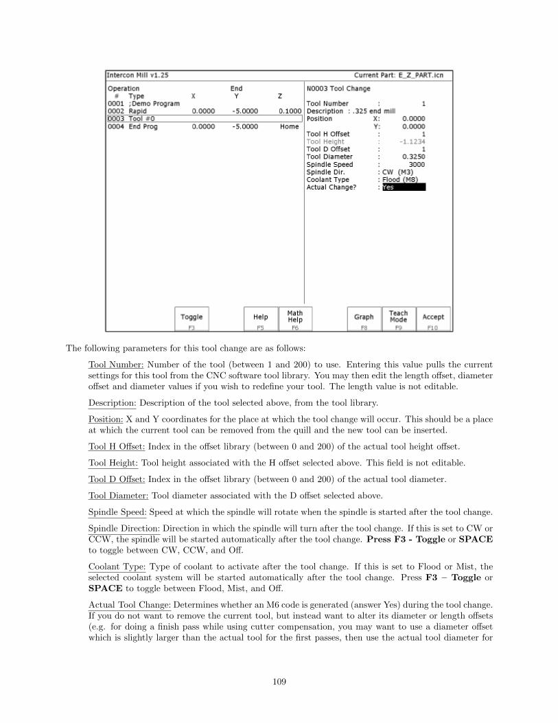
The following parameters for this tool change are as follows:
Tool Number: Number of the tool (between 1 and 200) to use. Entering this value pulls the currentsettings for this tool from the CNC software tool library. You may then edit the length offset, diameteroffset and diameter values if you wish to redefine your tool. The length value is not editable.
Description: Description of the tool selected above, from the tool library.
Position: X and Y coordinates for the place at which the tool change will occur. This should be a placeat which the current tool can be removed from the quill and the new tool can be inserted.
Tool H Offset: Index in the offset library (between 0 and 200) of the actual tool height offset.
Tool Height: Tool height associated with the H offset selected above. This field is not editable.
Tool D Offset: Index in the offset library (between 0 and 200) of the actual tool diameter.
Tool Diameter: Tool diameter associated with the D offset selected above.
Spindle Speed: Speed at which the spindle will rotate when the spindle is started after the tool change.
Spindle Direction: Direction in which the spindle will turn after the tool change. If this is set to CW orCCW, the spindle will be started automatically after the tool change. Press F3 - Toggle or SPACEto toggle between CW, CCW, and Off.
Coolant Type: Type of coolant to activate after the tool change. If this is set to Flood or Mist, theselected coolant system will be started automatically after the tool change. Press F3 – Toggle orSPACE to toggle between Flood, Mist, and Off.
Actual Tool Change: Determines whether an M6 code is generated (answer Yes) during the tool change.If you do not want to remove the current tool, but instead want to alter its diameter or length offsets(e.g. for doing a finish pass while using cutter compensation, you may want to use a diameter offsetwhich is slightly larger than the actual tool for the first passes, then use the actual tool diameter for
109

the finish pass), answer No to this question. Spindle and coolant will not be automatically turned offif you answer No here.
Press F10 - Accept, Page Up, or Page Down when you are finished to accept these values and makechanges to the tool library. If you have changed any field other than the Tool Number of the ActualTool Change field or position, you will make changes to the CNC software Tool Library. At the end of theprogram, Intercon always turns off the spindle and coolant and returns the Z-axis to the home position.These codes do not need to be entered at the end of your program.
10.7.5 F5 – Canned Cycles
When you choose the Canned Cycle operation by pressing F5 - Cycles, the following screen appears:
Canned Cycle Introduction #1: Using Pattern and Repeat (Drilling, Boring, Tapping)
Selecting F1 – Drill will give you four choices; F1 -– Drill, F2 -– Drill BHC, F3 -– Drill Array, orF4 -– Drill Repeat. F2 – Bore and F3 – Tap will have the same menu selections as drill except theywill display Bore or Tap cycles
110

All canned cycle operations using the Drill BHC (Bolt Hole Circle) or Drill Array are identical to theirequivalent using the F1 – Drill single hole selection. The use of the Drill BHC or Drill Array, however,offers the option to drill more than one hole in a pattern dictated by the new fields in the menu. F4 – DrillRepeat allows the user to repeat a set of holes with a different type drilling, boring or tapping operation without re-entering the X, Y coordinates. The Bolt Hole Circle and array patterns are explained graphically inthe following figure:
Canned Cycle Introduction #2: Linear Repetition of Operations (Drilling, Boring, Tapping)
If you want to perform one operation several times in a linear pattern, simply define Position X, Y or bothas incremental values. To do this, use the F1 – Abs/Inc Key. This key will toggle the Position value modebetween incremental and absolute. If you define X and/or Y as incremental values, a new field will appearasking for the number of holes:
111

The numbers in the fields on the screen correspond to the following example, shown here graphically:
Drilling (F1 in the Canned Cycle Menu: Option #1)
If you press F1 – Drill from the Canned Cycle Menu, you will gain access to three types of drilling operations:Drilling, Chip Breaking, and Deep Hole drilling. The current drilling operation in use is reflected in thefield “Cycle Type” and pressing F3 – Toggle or SPACE toggles between all three. In this section we willexamine the first option: Drilling.
112

The numbers in the fields on the screen correspond to the following example, shown here graphically:
Where:
Cycle Type: Selects one of three drilling operations: Drilling, Chip Breaking, or Deep Hole drilling.Press F3 – Toggle or SPACE to toggle between the three choices.
Position: Specifies the X and Y coordinates where the drilling will take place. If either the X or Ycoordinate is an incremental value, you will have the option to drill multiple holes in a linear pattern(See Canned Cycle Introduction #2).
113

Surface Height: Absolute Z-axis position from where each incremental depth is measured.
Clearance Height: This parameter specifies the Z-axis height used when performing rapid moves to theposition of each hole being drilled.
’Rapid To’ Depth: The depth to which the cutter rapid moves before beginning to drill the hole at thespecified Plunge Rate. This is below the Clearance Height but above the Surface Height.
Depth: Total: Depth of hole (incremental) as measured from Surface Height.
Plunge Rate: Z-axis speed of descent during drilling. The plunge rate can be toggled to modal, fixedor slave, this is indicated by the symbol beside the plunge rate field. If the plunge rate is modal thenit will have the “M” symbol or if it is fixed it will have the “F” symbol. The slave plunge rate hasno symbol and is set to the last modal plunge rate set in the program, when the modal plunge ratechanges all the following slave plunge rates change until the next modal plunge rate is encountered.
Dwell Time: Delay at bottom of hole before starting ascent.
Drilling provides a rapid to the hole position at the Clearance Height, followed by a rapid Z down to the’Rapid To’ Depth. Next is a feedrate down to the specified depth. If a Spot facing cycle is desired, enter avalue in the dwell time field and the cutter will wait the desired amount of time before performing a rapidmove up to the Clearance Height.
Chip Breaking (F1 in the Canned Cycle Menu: Option #2)
If you press F1 – Drill from the Canned Cycle Menu you will gain access to three types of drilling operations:Drilling, Chip Breaking, and Deep Hole drilling. The current drilling operation in use is reflected in thefield Cycle Type, and pressing F3 – Toggle or SPACE toggles between all three. In this section we willexamine the second option: Chip Breaking.
The numbers in the fields on the screen correspond to the following example, shown here graphically:
114

Where:
Cycle Type: Selects one of three drilling operations: Drilling, Chip Breaking, or Deep Hole drilling.Press F3 – Toggle or SPACE to toggle between the three choices.
Position: Specifies the X and Y coordinates where the drilling will take place. If either the X or Ycoordinate is an incremental value, you will have the option to drill multiple holes in a linear pattern(See Canned Cycle Introduction #2).
Surface Height: Absolute Z-axis position from where each incremental depth is measured.
Clearance Height: This parameter specifies the Z-axis height used when performing rapid moves to theposition of each hole being drilled.
’Rapid To’ Depth: The depth to which the cutter rapid moves before beginning to drill the hole at thespecified Plunge Rate. This is below the Clearance Height but above the Surface Height.
Depth: Total: Depth of hole (incremental) as measured from Surface Height.
Depth: Increment: Depth of each individual peck.
Peck Clearance: Distance the tool retracts before drilling the next peck.
Plunge Rate: Z-axis speed of descent during drilling. The plunge rate can be toggled to modal, fixedor slave, this is indicated by the symbol beside the plunge rate field. If the plunge rate is modal thenit will have the “M” symbol or if it is fixed it will have the “F” symbol. The slave plunge rate hasno symbol and is set to the last modal plunge rate set in the program, when the modal plunge ratechanges all the following slave plunge rates change until the next modal plunge rate is encountered.
Deep Hole Drilling (F1 in the Canned Cycle Menu: Option #3)
If you press F1 – Drill from the Canned Cycle Menu you will gain access to three types of drilling operations:Drilling, Chip Breaking, and Deep Hole drilling. The current drilling operation in use is reflected in thefield Cycle Type, and pressing F3 – Toggle or SPACE toggles between all three. In this section we willexamine the third option: Deep Hole drilling.
115

The numbers in the fields on the screen correspond to the following example, shown here graphically:
Where:
Cycle Type: Selects one of three drilling operations: Drilling, Chip Breaking, or Deep Hole drilling.Press F3–Toggle or SPACE to toggle between the three choices.
Position: Specifies the X and Y coordinates where the drilling will take place. If either the X or Ycoordinate is an incremental value, you will have the option to drill multiple holes in a linear pattern
116

(See Canned Cycle Introduction #2).
Surface Height: Absolute Z-axis position from where each incremental depth is measured.
Clearance Height: This parameter specifies the Z-axis height used when performing rapid moves to theposition of each hole being drilled.
’Rapid To’ Depth: The depth to which the cutter rapid moves before beginning to drill the hole at thespecified Plunge Rate. This is below the Clearance Height but above the Surface Height.
Depth: Total: Depth of hole (incremental) as measured from Surface Height.
Depth: Increment: Depth of each individual step of the drilling.
Rapid Clearance: Distance from the last incremental depth drilled that the tool rapid moves beforestarting the next plunge.
Plunge Rate: Z-axis speed of descent during drilling. The plunge rate can be toggled to modal, fixedor slave, this is indicated by the symbol beside the plunge rate field. If the plunge rate is modal thenit will have the “M” symbol or if it is fixed it will have the “F” symbol. The slave plunge rate hasno symbol and is set to the last modal plunge rate set in the program, when the modal plunge ratechanges all the following slave plunge rates change until the next modal plunge rate is encountered.
Boring (F2 in the Canned Cycle Menu)
If you press F2 – Bore from the Canned Cycle Menu you will gain access to the boring operation:
The numbers in the fields on the screen correspond to the following example, shown here graphically:
117

Where:
Position: Specifies the X and Y coordinates where the boring will take place. If either the X or Ycoordinate is an incremental value, you will have the option to bore multiple holes in a linear pattern.(See Canned Cycle Introduction #2)
Surface Height: Absolute Z-axis position from where each incremental depth is measured.
Clearance Height: This parameter specifies the Z-axis height used when performing rapid moves to theposition of each hole being drilled.
’Rapid To’ Depth: The depth to which the cutter rapid moves before beginning to drill the hole at thespecified Plunge Rate. This is below the Clearance Height but above the Surface Height.
Hole Depth: Depth of hole (incremental) as measured from Surface Height.
Plunge Rate: Z-axis speed of descent during drilling. The plunge rate can be toggled to modal, fixedor slave, this is indicated by the symbol beside the plunge rate field. If the plunge rate is modal thenit will have the “M” symbol or if it is fixed it will have the “F” symbol . The slave plunge rate hasno symbol and is set to the last modal plunge rate set in the program, when the modal plunge ratechanges all the following slave plunge rates change until the next modal plunge rate is encountered.
Dwell Time: Delay at bottom of hole before starting ascent.
Bore Tool Type: Standard - The tool will bore down at a feed rate and feed backup at a feed rate.Single Point – The tool will feed down at specified feedrate, Spindle will orient to the M19 positionand stop. The tool will retract in the X or Y direction by the angle specified by machine parameter136 and then retract at a Rapid feeedrate. The spindle will turn back on when it reaches the Rapidto Depth height. Note: Single Point bore tool feature uses G76 which needs M19 to orient the spindlebefore retract
Retract Shift: Only displayed with Single Point Bore Tool Type. This is the amount to shift away inthe X or Y direction from the surface before retracting.
118
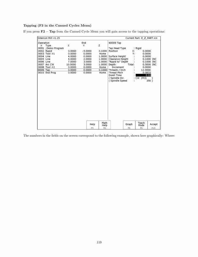
Tapping (F3 in the Canned Cycles Menu)
If you press F2 – Tap from the Canned Cycle Menu you will gain access to the tapping operations:
The numbers in the fields on the screen correspond to the following example, shown here graphically: Where:
119

Where:
Tap Head Type: Without rigid tapping, this selects either Floating tap head or Reversing tap head(where the special tapping head reverses for you). If rigid tapping is enabled (requires a spindleencoder), you can select either rigid or reversing.
Spindle Direction: Shows the current spindle direction. The spindle direction should be CW for right-hand tapping, and CCW for left-hand tapping. The spindle speed and direction appropriate for thetapping tool should be set in the tool change in which the tapping tool was loaded. This field will behidden if a reversing tap head is used.
WARNING: The tap must be rotating in the correct direction before performing this operation.
Position: Specifies the X and Y coordinates where the tapping will take place. If either the X or Ycoordinate is an incremental value, you will have the option to tap multiple holes in a linear pattern.(See Canned Cycle Introduction #2)
Surface Height: Absolute Z-axis position from where each incremental depth is measured.
Clearance Height: This parameter specifies the Z-axis height used when performing rapid moves to theposition of each hole being drilled.
’Rapid To’ Depth: The depth to which the cutter rapid moves before beginning to drill the hole at thespecified Plunge Rate. This is below the Clearance Height but above the Surface Height.
Depth Total: Depth of hole (incremental) as measured from Surface Height.
Depth Increment: (available only on rigid tapping.) This sets the length of each progressive ”peck”down the hole.
Threads / Unit: Number of threads on each inch/mm of the tap. Used in conjunction with the SpindleSpeed to calculate the appropriate plunge rate (Plunge Rate = Spindle Speed / Threads per Unit).
120

Spindle Speed: Rate at which the spindle rotates. Used in conjunction with the Threads / Unit tocalculate the plunge
WARNING: The spindle speed must be set before performing this operation. rate.
Dwell Time: Delay at bottom of hole before starting ascent. This is used for a floating tap to allow thespindle time to reverse direction at the bottom of the hole. A default value of 0.1 seconds is suggested.This field will be hidden if a reversing tap head is used; the tap head will reverse direction when thequill begins ascending.
NOTE: When using low gear for tapping, the spindle may turn opposite the direction specified. Theoperator is responsible for setting the correct spindle speed and direction.
Facing (F4 in the Canned Cycles Menu)
If you press F4 – Face at the Canned Cycle Selection Menu, the following screen is displayed:
The parameters in the previous screen correspond to the following dimensions:
121

Start: X and Y coordinates of the starting corner of the area to be faced.
Surface Height: Z coordinate of the top of the area to be faced.
Length: X-axis dimension of the area to be faced. If a negative value is entered for the length, thefacing will occur in the negative X-axis direction from the X-axis start position; otherwise, facing willoccur in the positive X-axis direction from the X-axis start position.
Width: Y-axis dimension of the area to be faced. If a negative value is entered for the width, the facingwill occur in the negative Y-axis direction from the Y-axis start position; otherwise, facing will occurin the positive Y-axis direction from the Y-axis start position.
Depth: Incremental amount of material to be removed from Surface Height.
Step Increment: Distance that the cutter will step over in the Y direction for each pass.
Plunge Rate: Z-axis speed of descent during facing. The plunge rate can be toggled to modal, fixedor slave, this is indicated by the symbol beside the plunge rate field. If the plunge rate is modal thenit will have the “M” symbol or if it is fixed it will have the “F” symbol. The slave plunge rate hasno symbol and is set to the last modal plunge rate set in the program, when the modal plunge ratechanges all the following slave plunge rates change until the next modal plunge rate is encountered.
Feedrate: Speed of the cutter during facing. The feedrate can be toggled to modal, fixed or slave, thisis indicated by the symbol beside the feedrate field. If the feedrate is modal then it will have the “M”symbol or if it is fixed it will have the “F” symbol shown below. The slave feedrate has no symbol andis set to the last modal feedrate set in the program, when the modal feedrate changes all the followingslave feedrates change until the next modal feedrate is encountered.
Rectangular Pocket (F5 in the Canned Cycles Menu)
Pressing F5 - Rect. Pocket from the Canned Cycle Selection Menu displays the following screen:
122

The parameters on the screen correspond to the following dimensions:
Where:
Center or Corner: Center - X and Y coordinates of the center of the Rectangular Pocket. Corner – Xand Y coordinates of the corner of the rectangular pocket. A positive or negative value in the lengthand width fields will determine the location of the rectangular pocket from the corner position.
Surface Height: Z-axis position from which each incremental depth is measured.
Length: X-axis dimension of the rectangular pocket.
Width: Y-axis dimension of the rectangular pocket.
123

Corner Radius: Radius of curvature of the corners. It cannot be smaller than the current cutter radius.
Depth: Total: Total depth of the rectangular pocket.
Depth: Per Pass: Depth of each individual pass.
Depth: Plunge Rate: Z-axis speed of descent.
Depth: Plunge Type: Straight or Ramped. Straight plunge does a vertical Z plunge with no X, Ymovement. Ramped plunge does a zigzag plunge limited by the Plunge Angle entered below.
Depth: Plunge Angle: The maximum limit angle allowed for a ramped plunge. A special value of 0means that there is no limit angle. Note: This field means nothing if the Plunge Type is Straight.
Rough Cuts: Selects type of rough cut: conventional or climb. Use F3 — Toggle or SPACE totoggle between them.
Rough Cuts: Stepover: Amount of material removed by cutter during each pass around the pocket.
Rough Cuts: Feedrate: Speed at which cutter performs rough cuts.
Finish Pass: Selects type of finish pass: climb, conventional or none at all. Use F3 – Toggle orSPACE to toggle between them.
Finish Pass: Amount: Amount of material to be removed on the finish pass.
Finish Pass: Feedrate: Speed at which cutter performs finish pass. The feedrate can be toggled tomodal, fixed or slave, this is indicated by the symbol beside the feedrate field. If the feedrate is modalthen it will have the “M” symbol or if it is fixed it will have the “F” symbol shown below. The slavefeedrate has no symbol and is set to the last modal feedrate set in the program, when the modalfeedrate changes all the following slave feedrates change until the next modal feedrate is encountered.
Circular Pocket (F6 in the Canned Cycles Menu)
When you press F6 - Circ. Pocket from the Canned Cycle Selection Menu, this screen is displayed:
124
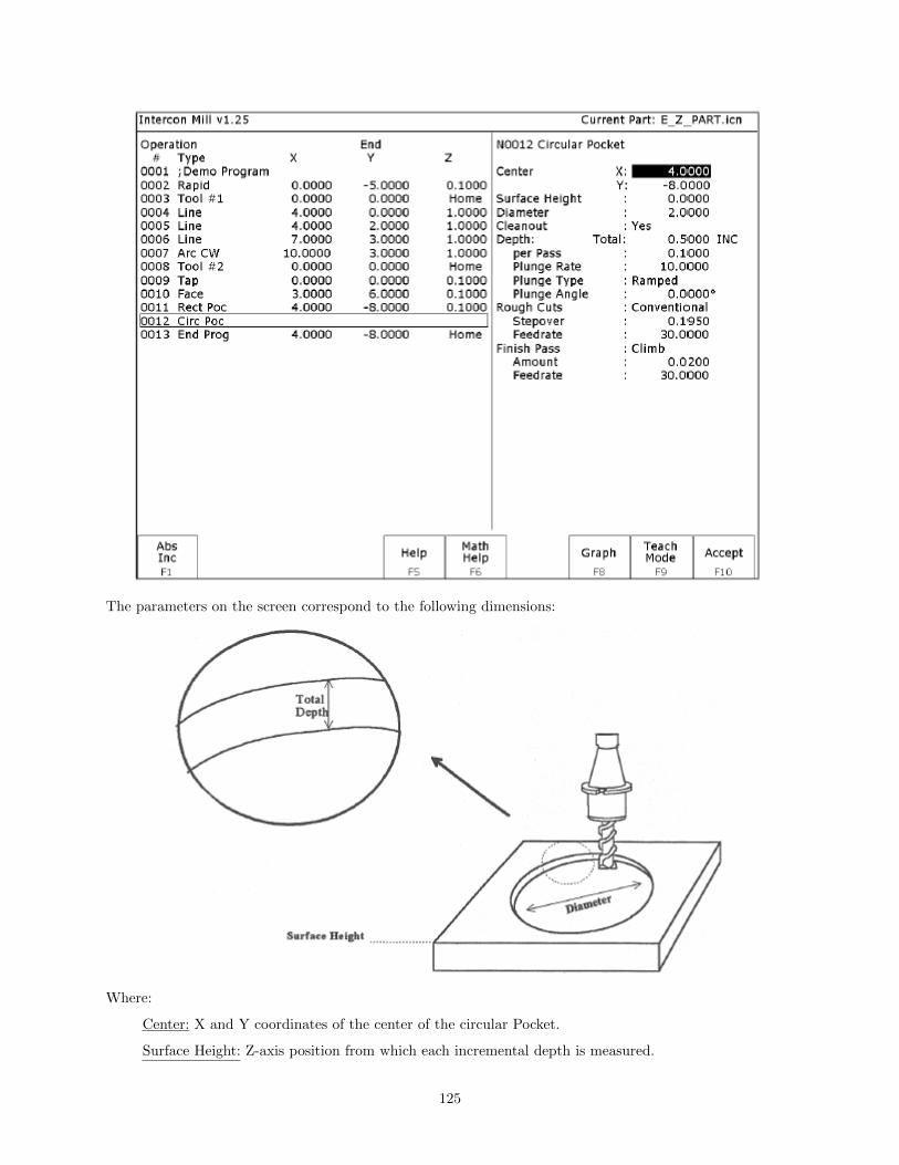
The parameters on the screen correspond to the following dimensions:
Where:
Center: X and Y coordinates of the center of the circular Pocket.
Surface Height: Z-axis position from which each incremental depth is measured.
125

Diameter: Diameter of circular pocket.
Cleanout: If cleanout is Yes, then all the material in the pocket will be removed. If cleanout is No,then all the material will not be removed. The cutter starts in the center of the pocket and arcing itsway out and then going around the frame.
Depth: Total: Total depth of the circular pocket.
Depth: Per Pass: Depth of each individual pass.
Depth: Plunge Rate: Z-axis speed of descent.
Depth: Plunge Type: Straight or Ramped. Straight plunge does a vertical Z plunge with no X, Ymovement. Ramped plunge does a zigzag plunge limited by the Plunge Angle entered below.
Depth: Plunge Angle: The maximum limit angle allowed for a ramped plunge. A special value of 0means that there is no limit angle. Note: This field means nothing if the Plunge Type is Straight.
Rough Cuts: Selects type of rough cut: conventional or climb. Use F3 – Toggle or SPACE to togglebetween them.
Rough Cuts: Stepover: Amount of material removed by cutter during each pass around the pocket.
Rough Cuts: Feedrate: Speed at which cutter performs rough cuts.
Finish Pass: Selects type of finish pass: climb, conventional or none at all. Use F3 – Toggle orSPACE to toggle.
Finish Pass: Amount: Amount of material to be removed on the finish pass.
Finish Pass: Feedrate: Speed at which cutter performs finish pass.
Rectangular or Circular Frame Milling (F7 in the Canned Cycle Menu)
When you press F7 - Frame from the Canned Cycle Selection Menu, the following screen is displayed:
126

The parameters on the screen correspond to the following dimensions (rectangular frame):
Where:
127

Frame Type: Selects Inside Rectangle, Outside Rectangle, Inside Circle, and Outside Circle. Press F3– Toggle or SPACE to toggle between them.
Center: X and Y coordinates of the center of the frame mill.
Surface Height: Z-axis position from where each incremental depth is measured. M-Series Operator’sManual 9/14/2016 29
Length: X-axis dimension of the frame mill. (Rectangular frame only.)
Width: Y-axis dimension of the frame mill. (Rectangular frame only.)
Corner Radius: Radius of curvature of the corners. On an Inside frame, corner radius must be greaterthan the current cutter radius. (Rectangular frame only.)
Diameter: Diameter of the frame mill. (Circular frame only)
Depth: Total: Total depth of the frame mill.
Depth: Per Pass: Depth of each individual pass.
Plunge Rate: Z-axis speed of descent.
Plunge Type: Straight or Ramped. Straight plunge does a vertical Z plunge with no X, Y movement.Ramped plunge does a zigzag plunge limited by the Plunge Angle entered below.
Plunge Angle: The maximum limit angle allowed for a ramped plunge. A special value of 0 means thatthere is no limit angle. Note: This field means nothing if the Plunge Type is Straight. Entrance Type:Selects type of entrance: Arc On or Arc Off, use F3 - Toggle or SPACE to toggle between them.(Circular frame only)
Cut type: Selects type of cut: conventional or climb, use F3 – Toggle or SPACE to toggle betweenthem.
Feedrate: Speed at which the cutter performs frame mill.
NOTE: To make a circular frame mill of radius R, specify R as the Corner Radius and set the Lengthand Width parameters equal to 2 x R.
Thread Milling (F8 in the Canned Cycles Menu)
When you press F8 - Thread from the canned cycle menu, the following screen is displayed:
128

The parameters on the screen correspond to the following:
Where:
Center: X and Y coordinates of the center of the thread mill operation.
129

Diameter: Major diameter of thread for internal thread milling and minor diameter for external threadmilling.
Thread / Unit: Number of threads per inch or mm. Used to calculate thread pitch.
Thread Pitch: Thread pitch calculated from threads/unit field. This field cannot be modified.
Thread Type: Specifies right or left hand threads.
Thread Direction: Specifies whether to start at the bottom of the hole and work up or start at the topof the hole and work down.
Tool Type: Single point or full form threading tool.
Thread Approach: Internal or external thread.
Clearance Amount: Used for external thread milling only. Specifies the diameter of the lead-in arc.Minimum clearance is 0.050 inches.
Clearance Angle: Used for external thread milling only. Specifies the angle from which the lead in arcwill start.
Feedrate: Cutting feed rate.
Surface Height: Absolute Z-axis position from position from where the incremental depth is measured.
Clearance Height: This parameter specifies the Z axis height used when performing rapid moves to theposition of each hole being thread.
’Rapid to’ Depth: The depth to which the cutter rapid moves before beginning to thread mill at thespecified Plunge Rate. This is below the Clearance Height but above the Surface Height.
Depth: The total depth of the thread.
Number of Passes: Number of times the thread mill is to be done on the same hole.
Cleanout (F9 in the Canned Cycles Menu)
The cleanout cycle performs a horizontal zigzag pocket cleanout of a profile composed of lines and arcs.When you press F9 - Cleanout from the canned cycle menu, the following screen is displayed:
130

Where:
Rough Cuts: Selects type of rough cut. Use F3-Toggle or SPACE to toggle between Conventionaland Climb.
Type: Selects type of cleanout to use. The choices are Collapse, which cleans out the pocket from theoutside in, or Expand, which cleans out the pocket from the inside out. You can switch between thetwo by using the F3-Toggle or SPACE keys
Stepover: The distance between each step in the pocket cleanout. This value cannot be greater than50% of the tool diameter.
Feedrate: Speed at which cutter performs rough cuts.
Finish Pass: Selects type of finish pass. Use F3-Toggle or SPACE to toggle between Conventional,Climb, or None.
Amount: Amount of material to be removed on the finish pass.
Feedrate: Speed at which cutter performs finish pass.
Tool Number: Tool number to be used for the finish pass.
Surface Height: The Z-axis position from where the incremental depth is measured.
Clearance Height: This parameter specifies the Z-axis height to which the tool is retracted beforemoving to different segments during a pocket cleanout.
’Rapid To’ Depth: The depth to which rapid positioning moves will be made to when moving the Zaxis downward.
Depth: Total: The total depth of the pocket measured as an incremental depth from the surface height.
per Pass: The depth amount of cut to be taken to reach the total depth. This value must be greaterthan 0.0 and cannot exceed the total depth.
131

Plunge Rate: The feedrate at which the Z axis is moved when plunging to a lower depth.
After the cleanout parameters are accepted, a screen similar to the following appears:
Key points about the Cleanout cycle:
• When creating a pocket the first move in your cleanout cycle must be a linear move.
• If the profile contour does not end at the start point, a linear segment will automatically be insertedto close the pocket.
• The last line of the contour will not include a connecting radius to the starting point.
Once you have defined the specifics of your cleanout cycle, the shape of your pocket will be defined througha series of lines and arcs by choosing the F2-Linear and F3-Arc options in the cleanout cycle.
F1-Island (Island Avoidance) Once you have defined a pocket in the cleanout cycle. There may be areas orislands that you don’t want cleaned out. To create an island press F1-Island, enter the starting point of theisland and then use F2-Linear and F3-Arc to create the island. See an example of a completed cleanoutbackplot below.
132

10.7.6 F6 - Other
Choosing F6 - Other will display the following operations that may be inserted.
F1 - Comment - Enter a comment, up to 35 characters long, which will be displayed in the generatedCNC program.
F2 - Spindle - Change the actual state of the spindle. Press F3 - Toggle or SPACE to togglebetween CW, CCW, and OFF.
F3 - Coolant - Change the actual state of the coolant. Press F3 - Toggle or SPACE to togglebetween FLOOD, MIST, and OFF.
F4 - Clamp - Turn the Clamp ON and OFF. Press F3 - Toggle or SPACE to change the clampstate.
F5 - Z Home - Send the Z-axis to its home position.
F6 - M & G Code - Enter M & G codes into your Intercon part program. Great care must be takenwhen using this function, as you could cause unpredictable results in the controller if you accidentallychanged positioning modes in your program, or perhaps turning the spindle off during a cut.
F7 - Rotary - Insert a rapid rotary move. This operation requires a rotary fourth axis. The fieldsare identical to the fields in the Linear Mill operation as shown below, but the resulting move is a G0(Rapid) moving only the rotary axis.
133

F8 - Import DXF - Insert Intercon operations created from objects in DXF files. For more informa-tion, refer to the “Importing DXF files” section later in this chapter.
10.7.7 F7 – Cutter Compensation
Pressing F7 – Cutter Comp from the Insert Operation screen, will insert a cutter compensation command.Press F3 – Toggle or SPACE to select cutter compensation Left, Right, or Off. Cutter compensationmay be used with Linear Mill, Frame Mill, and Rapid Traverse operations. For details on using cuttercompensation, see the section ”G40, G41, G42 -Cutter Compensation” in Chapter 12.
The Rectangular Pocket, Circular Pocket, Frame Mill and Cleanout canned cycles perform cutter compen-sation automatically. If compensation left or right was selected before the canned cycle, it will be turnedoff.
10.7.8 F9 – Subprograms
Intercon subprograms allow you to make additional copies of a programmed contour. The copies maybe repeated in the x/y axes, depth repeat, rotated, or even a mirror image of the original. To create asubprogram, first define the operations that will compose the contour. Any type of program operation (rapid,linear mill, arc mill, canned cycle, subprogram, etc.) may be included in the contour. These operations mustbe programmed at the Z depth at which the first pass will occur. When you are finished doing this, returnto the Program Edit Menu. Move to the place in the program where you want to repeat these operationsand press the F3 - Insert key. The operations will be performed once before the repeat operation occurs;therefore the operations to compose the contour should be defined at the place in the program where theyshould occur first.
When you press F9 - Subpgm from the Insert Operation screen you will see the Insert Subprogram screen:
You may now select the type of subprogram desired.
A typical subprogram screen appears as follows:
134

All subprogram operations contain the following fields:
Start Block: Selects the first operation in the block of operations to repeat. This operation must liebefore the place in your program where you are trying to repeat operations.
End Block: Selects the last operation in the block of operations to repeat. Again, this operation mustlie prior to place in your program where you are trying to repeat operations, but not precede the startblock.
Clearance Height: This field determines the Z height at which the tool is moved over the work piecebefore being repositioned at the start of the contour. This value must meet or exceed the maximum Zheight of all operations contained within the contour. If any operation places the tool at the Z homeposition, then you must tie this value to the home position (F2 - Z Home).
Plunge Rate: This is the speed at which the tool is repositioned on the Z-axis when moving to thebeginning of the first move of the contour. This has no effect on a plunge that you have programmedinto the contour; however, this has the effect of providing a vertical plunge for you in the event thatyou do not program your own plunge into the contour.
Other fields specific to the various subprogram operations are described in the next few pages.
135

Repeat to Depth (F1 in the Insert Subprogram Menu)
The Repeat to Depth feature is useful for repeating a part contour when the material being machined is toothick to cut in just one pass. The contour formed by these operations may either be a closed contour or anopen one. If a non-vertical plunge to the start of the contour is desired, it must be programmed into thecontour (a vertical plunge between passes will be provided if one is not programmed).
Total Depth: Indicates how deep the final depth pass is to be. This is a positive value. Note that becausethe contour has been programmed at a depth of one depth increment below the work piece surface, the finaldepth assumes that one depth pass has already been performed, and, thus, subtracts one depth incrementfrom the total depth.
Depth Increment: Specifies the distance to drop each time the contour is repeated. This is a positive valuethat may not exceed the total depth of the operation.
When you have finished entering the required parameters, press F10 - Accept to accept them. An operationlabeled “Depth Rpt” will be inserted into your program in front of the highlighted operation. You may nowedit this operation just as you would edit any other operation (use the cursor keys to highlight the “DepthRpt” operation, and then press ENTER.
* NOTE: If you wish to change the amount of the depth increment per pass after the contour has beenprogrammed, you must also change the Z depth of all the operations inside the contour to correspond to thenew increment.
Repeat (F2 in the Insert Subprogram Menu)
The Repeat feature is useful for repeating a part contour one or more times along a straight line in the XYplane. The contour formed by these operations may either be closed or open. If a rotary axis is enabled, thisoperation can also be used for repeating such a contour one or more times over a specified rotary increment.
136

Increment: Specifies the X and Y distances between the start points of each copy of the contour.
Rotary Increment: Specifies the rotary incremental amount to move between each copy of the contour. Note:This field will appear only if a rotary axis is enabled.
Number of Copies: The number of times to repeat the contour.
Skip List: List of copies that are skipped. Enter the number or numbers of the copies that you wish to skip.In the example below will skip copy # 2.
* NOTE: An array of repeats may be accomplished by doing a repeat of a repeat.
Mirror (F3 in the Insert Subprogram Menu)
The Mirror feature is useful for reflecting a part contour over a line. The contour formed by these operationsmay either be closed or open.
137

Mirror Line: Specifies the type of mirror line to use. Choices are Horizontal, Vertical and Other (user-defined).
X Offset: Specifies the X coordinate on the Mirror Line. This field will not be visible for a horizontal mirrorline.
Y Offset: Specifies the Y coordinate on the Mirror Line. This field will not be visible for a vertical mirrorline.
Angle: Specifies the angle (from the three o’clock position) of the Mirror Line. This field will only be visiblefor a user-defined mirror line and is used in conjunction with the X Offset and Y Offset fields to define themirror line.
Rotate (F4 in the Insert Subprogram Menu)
The Rotate feature is useful for rotating a part contour multiple times around a given point. The contourformed by these operations may either be closed or open.
Center: The XY location of the center of rotation.
Start Angle: The angle from the original copy at which the first copy will be placed. A positive angleindicates a counterclockwise rotation, while a negative angle indicates a clockwise rotation.
Angle Increment: The angle at which each copy after the first will be placed from the first copy. A positiveangle indicates a counterclockwise, while a negative angle indicates a clockwise rotation. Must have a value
138
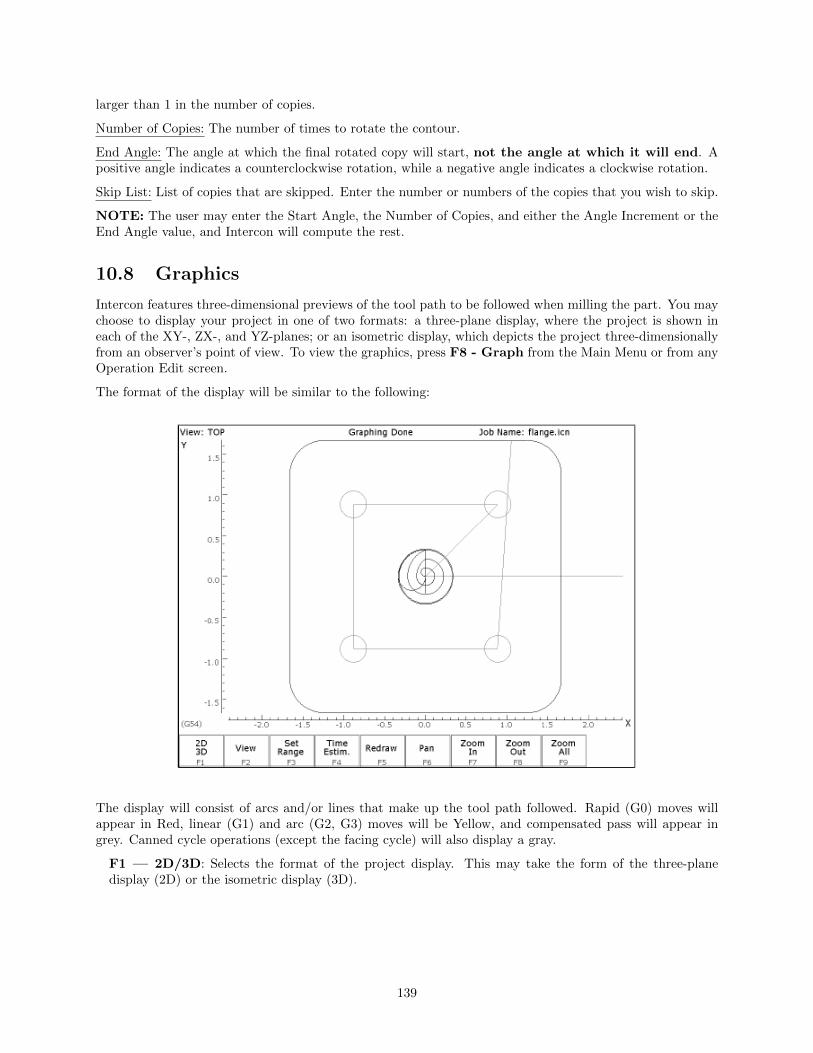
larger than 1 in the number of copies.
Number of Copies: The number of times to rotate the contour.
End Angle: The angle at which the final rotated copy will start, not the angle at which it will end. Apositive angle indicates a counterclockwise rotation, while a negative angle indicates a clockwise rotation.
Skip List: List of copies that are skipped. Enter the number or numbers of the copies that you wish to skip.
NOTE: The user may enter the Start Angle, the Number of Copies, and either the Angle Increment or theEnd Angle value, and Intercon will compute the rest.
10.8 Graphics
Intercon features three-dimensional previews of the tool path to be followed when milling the part. You maychoose to display your project in one of two formats: a three-plane display, where the project is shown ineach of the XY-, ZX-, and YZ-planes; or an isometric display, which depicts the project three-dimensionallyfrom an observer’s point of view. To view the graphics, press F8 - Graph from the Main Menu or from anyOperation Edit screen.
The format of the display will be similar to the following:
The display will consist of arcs and/or lines that make up the tool path followed. Rapid (G0) moves willappear in Red, linear (G1) and arc (G2, G3) moves will be Yellow, and compensated pass will appear ingrey. Canned cycle operations (except the facing cycle) will also display a gray.
F1 — 2D/3D: Selects the format of the project display. This may take the form of the three-planedisplay (2D) or the isometric display (3D).
139
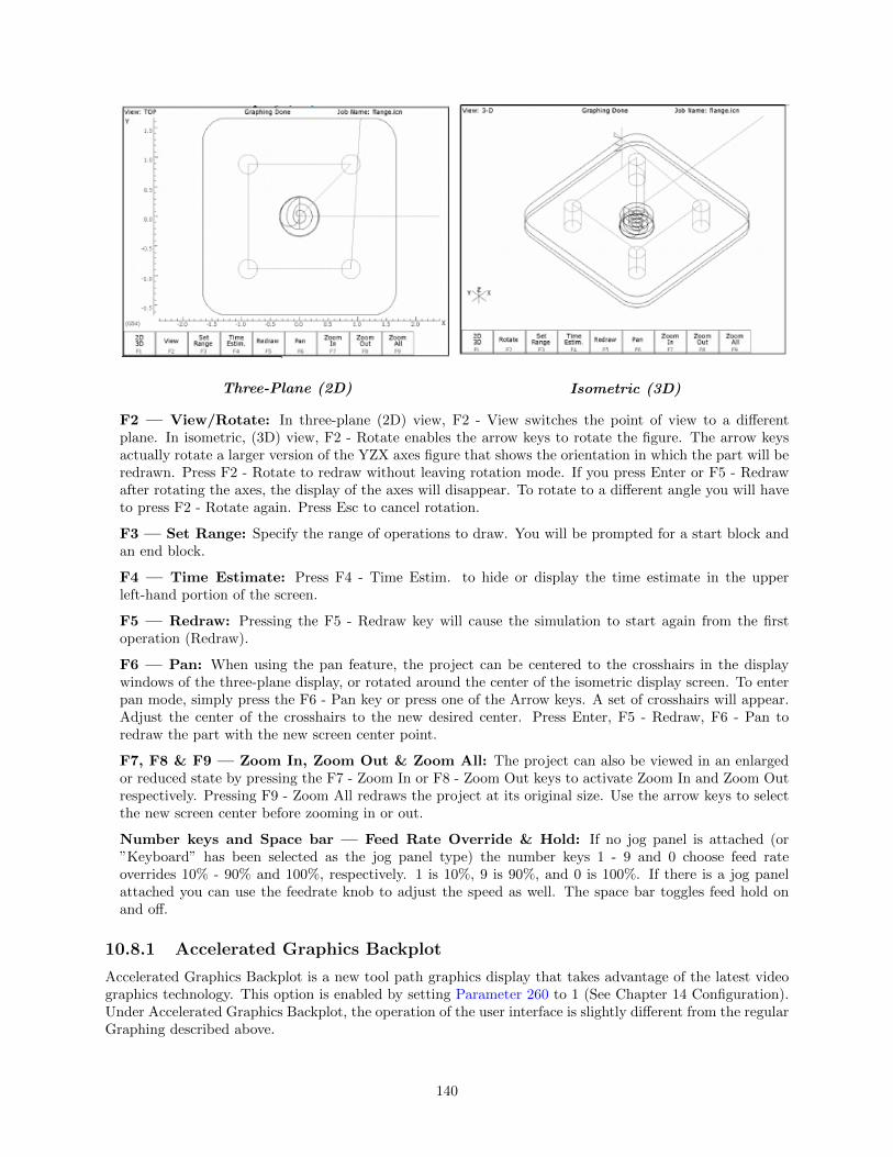
Three-Plane (2D) Isometric (3D)
F2 — View/Rotate: In three-plane (2D) view, F2 - View switches the point of view to a differentplane. In isometric, (3D) view, F2 - Rotate enables the arrow keys to rotate the figure. The arrow keysactually rotate a larger version of the YZX axes figure that shows the orientation in which the part will beredrawn. Press F2 - Rotate to redraw without leaving rotation mode. If you press Enter or F5 - Redrawafter rotating the axes, the display of the axes will disappear. To rotate to a different angle you will haveto press F2 - Rotate again. Press Esc to cancel rotation.
F3 — Set Range: Specify the range of operations to draw. You will be prompted for a start block andan end block.
F4 — Time Estimate: Press F4 - Time Estim. to hide or display the time estimate in the upperleft-hand portion of the screen.
F5 — Redraw: Pressing the F5 - Redraw key will cause the simulation to start again from the firstoperation (Redraw).
F6 — Pan: When using the pan feature, the project can be centered to the crosshairs in the displaywindows of the three-plane display, or rotated around the center of the isometric display screen. To enterpan mode, simply press the F6 - Pan key or press one of the Arrow keys. A set of crosshairs will appear.Adjust the center of the crosshairs to the new desired center. Press Enter, F5 - Redraw, F6 - Pan toredraw the part with the new screen center point.
F7, F8 & F9 — Zoom In, Zoom Out & Zoom All: The project can also be viewed in an enlargedor reduced state by pressing the F7 - Zoom In or F8 - Zoom Out keys to activate Zoom In and Zoom Outrespectively. Pressing F9 - Zoom All redraws the project at its original size. Use the arrow keys to selectthe new screen center before zooming in or out.
Number keys and Space bar — Feed Rate Override & Hold: If no jog panel is attached (or”Keyboard” has been selected as the jog panel type) the number keys 1 - 9 and 0 choose feed rateoverrides 10% - 90% and 100%, respectively. 1 is 10%, 9 is 90%, and 0 is 100%. If there is a jog panelattached you can use the feedrate knob to adjust the speed as well. The space bar toggles feed hold onand off.
10.8.1 Accelerated Graphics Backplot
Accelerated Graphics Backplot is a new tool path graphics display that takes advantage of the latest videographics technology. This option is enabled by setting Parameter 260 to 1 (See Chapter 14 Configuration).Under Accelerated Graphics Backplot, the operation of the user interface is slightly different from the regularGraphing described above.
140

F1 - Pan/Rotate Press this key to change the behavior of the keyboard arrow keys. Normally,they will pan (scroll) around the drawing, but after pressing this key thearrow keys will control rotation instead. When in rotation mode, an axisindicator is drawn to mark the center of rotation.
F2 - View Press this key to change the planar view of your part. The view is indicatedby TOP, RIGHT, or FRONT shown at the top of the screen.
F3 - Set Range Press this key to select which blocks of G-code to display. Only blocks thatfall within the range you specify will be drawn.
F4 — Dimension Menu Press this key to access a sub-menu of options:
F1 –– Prev Line: Press this to walk forward to the next G-code lineand graphically highlight it. If this G-code linecontains movement, the Start and End points willbe displayed at the bottom of the screen.
F2 –– Next Line: Press this to walk backward to the previous G-codeline and graphically highlight it. If this G-code linecontains movement, the Start and End points willbe displayed at the bottom of the screen.
F3 —- Go To Line: Press this key to graphically highlight a particularG-code line whose line number you specify. If thisG-code line contains movement, the Start and Endpoints will be displayed.
F4 —- Measure: Use this feature to measure between any 2 selectedpoints. To do this, use a mouse to move the pointerover the first point and then press F4 – Measure toanchor the first point. Then use the mouse to movethe pointer to the second point. As you move themouse towards the second point, you will notice anOffset and Measurement display changing dynam-ically as you move the mouse. Also you may no-tice some ”snap to” effects as you move the pointerclose to start and end points of entities that makeup your program.
F5 — Redraw Press this key to redraw the part slowly, which can be useful for visualizingthe movements the machine will make. While the display is being redrawn,you can use the feedrate override knob to adjust the rate at which it is beingdrawn. If you don’t have a feedrate override knob, the + and - keys can beused to adjust the rate. Pressing F5 again will cancel this mode.
F6 — Hide Rapids Press this key to hide rapid movements. Press it again to show them.
F7 — Zoom In Press these keys to zoom into the part relative to the center of the screen.
F8 — Zoom Out Press these keys to zoom away from the part relative to the center of thescreen.
F9 — Zoom All Press this key to fit the entire part inside the screen.
141

F10 — Show Tools Press this key to show the tools menu, which allows you to highlight move-ments of certain tools. Press this key again to hide the tools menu.
Spacebar — Measure Press this key to take a measurement between two points. In a 2D view,this measurement will be a 2D measurement. In a 3D view, it will be a 3Dmeasurement (and the measurement will only be valid if the crosshairs aresnapped to a line of the tool path).
NOTE: If you have a mouse or touch screen attached to your device, you can use that to control the graphingwindow. Holding the left mouse button allows you to drag the part across the screen, while the right mousebutton controls rotation of the part. Spinning the mouse wheel (or holding both left and right buttons)zooms in and out. Double clicking on a feedrate movement will center the camera on that movement (whichis very useful) and also tells you the length of that movement. For touchscreen operation, use the F1 key toswitch between Pan and Rotate modes.
10.9 Math Help
Intercon provides a math assistance function to solve the trigonometric problems common in part drawings.To enter Math Help, press F6 — Math Help from any Edit Operation screen. The first time that youinvoke Math Help, the following screen appears which shows all available solvers:
The figures on the right are a graphical representation of the highlighted solver on the left. Pressing EN-TER key will display another menu that has various fields particular to the type of problem that is beingsolved. The graphic below displays the Right Triangle Calculator menu. The options that are available onthe function keys are the same for every type of math help solver and perform the following operations:
142
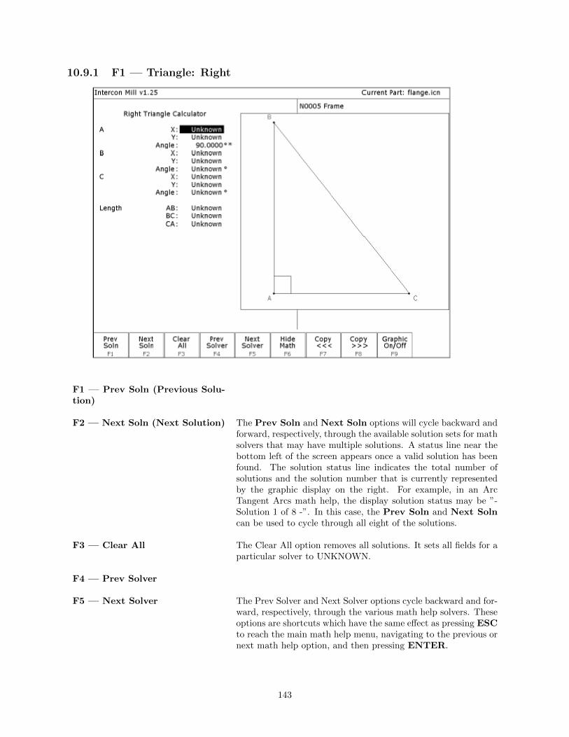
10.9.1 F1 — Triangle: Right
F1 — Prev Soln (Previous Solu-tion)
F2 — Next Soln (Next Solution) The Prev Soln and Next Soln options will cycle backward andforward, respectively, through the available solution sets for mathsolvers that may have multiple solutions. A status line near thebottom left of the screen appears once a valid solution has beenfound. The solution status line indicates the total number ofsolutions and the solution number that is currently representedby the graphic display on the right. For example, in an ArcTangent Arcs math help, the display solution status may be ”-Solution 1 of 8 -”. In this case, the Prev Soln and Next Solncan be used to cycle through all eight of the solutions.
F3 — Clear All The Clear All option removes all solutions. It sets all fields for aparticular solver to UNKNOWN.
F4 — Prev Solver
F5 –– Next Solver The Prev Solver and Next Solver options cycle backward and for-ward, respectively, through the various math help solvers. Theseoptions are shortcuts which have the same effect as pressing ESCto reach the main math help menu, navigating to the previous ornext math help option, and then pressing ENTER.
143

F6 –– Hide Math The F6 - Hide Math option exits math help mode and returnsto the operation edit menu. Pressing F6 - Math Help to invokeMath Help again will restore Math Help exactly as you left it.After copying values from Math Help, you can press F6 - HideMath to hide Math Help, and then hit F10 - Accept to acceptthe values entered.
F7 — Copy <<<
F8 — Copy >>> The F8 — Copy <<< option will move the value fromthe selected edit operation field into the selected math helpmenu field and the F7 — Copy >>> operation will movethe value from the selected math help menu field into theselected edit operation field. For both options, the selectedfields in the math help menu and the operation edit menuare advanced. Only when the graphics display is off will theCopy operations actually copy values and advance field selections.
The currently selected fields have either a box drawn aroundthem or are highlighted depending upon which menu is active.The active menu, which is either the math operation menu onthe left hand side or the operation edit menu on the right handside, depicts the selected field by highlighting the entire field.The non-active menu displays the active field with a box drawnaround it. Use the arrow keys to select fields as described below.
F9 — Graphic On/Off Toggle the graphical representation of the math help menu on thedisplay.
↑↓←→ (Arrow Keys) — SelectFields
The LEFT and RIGHT arrow keys are used to navigate betweenthe math menu and the edit menu. The UP and DOWN arrowkeys are used to navigate within a menu. To choose fields forthe ”Copy” option, above, use the UP and DOWN arrow keysto highlight the desired field in the menu and use the LEFT orRIGHT arrow keys to switch menus.
Other Features Common To All Math Help OperationsIn some math help operations, there will be an asterisk ’*’ character that appears immediately to the rightof a field. This character marks the field as a ”given” field, which means that the value of this field will beheld constant in the process of solving the math equations.
144

10.9.2 F2 — Triangle:Other
See button explanations above in the F1 — Triangle: Right section.
The screen will show UNKNOWN if the value of each parameter is not known. Math Help waits for knownvalues to be entered, where:
Point a, b, or c is the coordinate value for each corner of the triangle.
Angle A, B, or C is the angle at each point of the triangle.
Length of values are the distances between the points indicated.
Continue adding all the known parameters. Select parameters using the arrow soft keys. When Math Helpsolves the remaining unknown values, the screen will display them.
145

10.9.3 F3 — Tangent: Line Arc
See button explanations above in the F1 — Triangle: Right section.
Given the center (C1) the radius of an arc, and 1 point (LP) on a line, find the lines tangent to the arc(defined by the tangent point (T1)).
You must enter the X and Y coordinates for the circle’s center point, the circle’s radius, and the X and Ycoordinates for a point on the line.
146

10.9.4 F4 — Tangent: Arc Arc
See button explanations above in the F1 — Triangle: Right section.
Given the center points (C1 and C2) and radii (R1 and R2) of two arcs, find the point (T) at which theyare tangent.
You must enter the X and Y coordinates for the first circle’s center point, the radius of the first circle, theX and Y coordinates for the second circle’s center point, and the second circle’s radius.
147
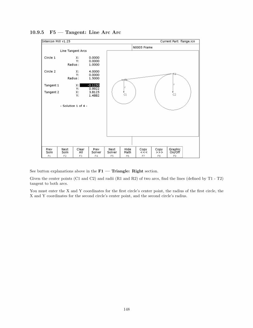
10.9.5 F5 — Tangent: Line Arc Arc
See button explanations above in the F1 — Triangle: Right section.
Given the center points (C1 and C2) and radii (R1 and R2) of two arcs, find the lines (defined by T1 - T2)tangent to both arcs.
You must enter the X and Y coordinates for the first circle’s center point, the radius of the first circle, theX and Y coordinates for the second circle’s center point, and the second circle’s radius.
148

10.9.6 F6 — Tangent: Arc Arc Arc
See button explanations above in the F1 — Triangle: Right section.
Given the center points (C1 and C2) and radii (R1 and R2) of two arcs and the radius of a third arc, findthe center point of the third arc and the tangent points (T1 and T2).
You must enter the radius of the tangent arc, the X and Y coordinates for the first circle’s center point, theradius of the first circle, the X and Y coordinates for the second circle’s center point, and the second circle’sradius.
149

10.9.7 F7 — Intersection: Line Line
See button explanations above in the F1 — Triangle: Right section.
You must enter the X and Y coordinates for 1 point on each line, and also one of the following:
• The X and Y coordinates for a second point.
• The X coordinate for a second point and the angle from horizontal.
• The Y coordinate for a second point and the angle from horizontal.
• The angle from horizontal only.
150

10.9.8 F8 — Intersection: Line Arc
See button explanations above in the F1 — Triangle: Right section.
Given the center (C1) and radius (R) of an arc, 1 point (P1) and either a second point (P2) or one coordinate(P2 X or Y) and the angle from horizontal, find the intersection point(s) (I1 and I2).
You must enter the X and Y coordinates for the circle’s center point, the circle’s radius, the X and Ycoordinates for one point on the line, and one of the following:
• The X and Y coordinates of a second point on the line.
• The X coordinate of a second point and the angle from horizontal.
• The Y coordinate of a second point and the angle from horizontal.
151

10.9.9 F9 — Intersection: Arc Arc
See button explanations above in the F1 — Triangle: Right section.
Given the center points (C1 and C2) and the radii (R1 and R2) of two arcs, find the intersection point(s)(I1 and I2) of the arcs.
You must enter the X and Y coordinates for the first circle’s center point, the radius of the first circle, theX and Y coordinates for the second circle’s center point, and the second circle’s radius.
10.10 Importing DXF files (Optional)
Intercon allows you to convert geometry in DXF files to Intercon operations. To insert operations from aDXF file press F6 — Other then F8 — Import DXF. If no DXF files have been loaded yet, the Interconload file menu will appear. From here you may select the DXF file you wish to load. By default, Interconexpects DXF files to reside in the c:\cncm\ncfiles directory. To change the default directory used by theIntercon load menu when loading DXF files, see the ”User Specified Paths” section of Chapter 14.
Intercon reads DXF files up to and including version R14. At this time, only point, line, arc, circle,polyline and lwpolyline entities can be used to create Intercon operations. All other entities such as textmust be converted to lines and arcs for them to appear in the Intercon Import DXF menu.
After a DXF file has been loaded, the Set zero reference menu appears.
152

This menu allows you to change the absolute zero reference of the DXF file. The current zero referenceappears as a green cross. All other points appear as gray crosses. A new zero reference may be defined by acombination the following methods:
• Press F1 — Input Zero to enter the coordinates of the new zero reference.
• Move the crosshairs with the arrow keys to highlight a point (represented by a gray cross) and whenthe crosshairs are close to a gray cross it will change red. Press F2 — Set Zero to set the zeroreference to the position of that point.
When satisfied with the current location of the zero reference, press F10 — Accept. The zero referencemay be changed multiple times before pressing F10 — Accept.
After the zero reference is set the Select Intercon operation menu appears:
153

This menu allows you to select the type of Intercon operation you wish to create using geometry from theDXF file.
F1 — Contour Convert one or more connected lines and/or arcs to linear and arc operations.
F2 — Pocket Convert a chain of lines and/or arcs to one of the Intercon pocket operations. Thetype of pocket depends on the geometry of the selected chain. A chain ofarcs will be converted to a circular pocket if all arcs have the same centerpoint and radius. A chain of four lines forming a rectangle will be convertedto a rectangular pocket. All other chains will be converted into a cleanoutoperation.
F3 — Frame Create a frame operation that surrounds a chain of lines and/or arcs. The height,width and center of the chain are used to define the frame.
F4 — Drill Convert one or more points to a drilling operation.
F5 — Bore Convert one or more points to a boring operation.
F6 — Tap Convert one or more points to a tapping operation.
F7 — Thread Convert one or more points to a threading operation.
F8 — Engrave (Optional) Converts the entire file to engraving operations. Choosing this option dis-plays the engraving menu. Set the options as desired for the engraving.Surface Height is the height of the surface to be engraved. ClearanceHeight is the height that the engraving tool will move up to clear thesurface. Depth is the depth of the engraving. Set the Plunge Rate andFeedrate appropriately for the tool and material.
154

F10 — File Pressing F10 — File displays the following options:
F1 — Load Load a new DXF file.
F2 — Zero Change the current zero reference.
F3 — Gap Modify the current gap tolerance. Two lines or arcsare connected if the distance between their end pointsis less than the gap tolerance.
Selecting DXF geometry
After selecting an operation to from the Select Intercon operation menu, one of two menus appears. Contour,pocket and frame operations display the Select Chain menu and Drill, Bore, Tap and Thread operationsdisplay the Select Point menu. These menus allow you to select the geometry you wish to use to create thespecified Intercon operation(s).
Select Chain Menu
This menu allows you to select a chain of one or more lines and/or arcs. To select a chain, highlight the firstline or arc with the crosshairs. Press either F2 — Single to accept only that object or press F3 — Chainto accept that object and create a chain of lines and arcs connected to that entity. When satisfied with theselected chain, press F10 — Done to edit the values for the chosen Intercon operation.
↑↓←→ (Arrow Keys) — Move crosshairs Use the arrow keys to move the crosshairs.
155

F1 — Reverse When a line or arc is highlighted, an arrow appears indicating the direction of theobject. Contour operations use this direction when cutting lines and arcs. To reversethe direction of the highlighted line or arc, press F1 — Reverse.
F2 — Single Select the currently highlighted line or arc.
F3 — Chain Select the currently highlighted line or arc and create a chain of connected lines orarcs in the direction of this selected object. Chaining will stop if there are no moreconnected, unselected lines or arcs, or the chain connects to the first object in thechain, or a branch point occurs. A branch point occurs when the last object in thechain is connected to more than one unselected lines or arcs. When this situationoccurs, highlight the desired unselected line or arc that connects to the last object inthe chain and press F3 — Chain to continue chaining.
F5 — Undo Unselect the last line or arc in the chain.
F6 — Pan Set the plot center to the center of the crosshairs.
F7, F8 & F9 —Zoom In, ZoomOut & Zoom All
F7 — Zoom In and F8 — Zoom Out, set the center of the plot to the center ofthe crosshairs and Zoom In and Zoom Out respectively. F9 — Zoom All redraws thepart with its original scale.
F10 – Done Accepts the selected chain and proceeds to the Intercon operation edit menu. Theoperation edit menu allows you to enter values for fields such as feedrate and plungerate. These values are copied to the rest of the lines and arcs in the chain whereapplicable.
156

The keys F1 — Reverse, F2 — Single and F3 — Chain only appear when a line or arc is highlighted.The keys F5 — Undo and F10 — Done only appear when one or more objects has been selected withF2 — Single or F3 — Chain.
Select Point Menu
This menu allows you to select one or more points to be converted into Intercon Drilling Threading op-erations. In this menu, all selectable points are displayed as gray crosses. Selectable points include pointentities, line/arc endpoints and arc/circle center points. To select a point, position the crosshairs over thedesired point until the cross turns red and press F2 — Single to accept the point. More points can beselected by highlighting them with the crosshairs and pressing F2 — Single. F1 — Window can be usedto select all points within a specified window. When satisfied with the selected point(s), press F10 — Doneto edit the Intercon operation parameters.
↑↓←→ (Arrow Keys) — Move crosshairs Use the arrow keys to move the crosshairs.
F1 — Window This key allows you to select all points within a specified box. Press F1 - Windowonce to set the first corner of the box. Move the crosshairs to the desired location forthe opposite corner of the box and press F1 — Window. All points within the boxare selected.
F2 — Single Accept the currently highlighted point.
F5 — Undo Unselect the last selected point.
157

F6, F7, F8 & F9— Pan, Zoom In,Zoom Out & ZoomAll
These keys perform the same operations they do in the Select Chain menu.
F10 – Done Accepts the selected points and proceeds to the Intercon operation edit menu. Theoperation edit menu allows you to enter values for fields such as plunge rate and depth.These values are copied to the rest of the selected operations where applicable.
The key F2 — Single only appears when a point is highlighted. The keys F5 — Undo and F10 — Doneonly appear when one or more points have been selected with F1 - Window or F2 — Single.
Using a mouseIn addition to the arrow keys, a mouse may be used to position the crosshairs in the DXF selection menus.Simply move the mouse pointer to the desired crosshair location and click the left mouse button. This actionwill move the crosshairs to the location of the mouse click and highlight the closest object.
158

10.11 Intercon Tutorial #1
This is a step-by-step instructional example of going from blueprint to part with Intercon. The tool path tobe created is for the part shown in Figure 1. For instructional purposes, this part will be programmed tocut into stock held in 3 fixtures, 6 inches apart along the X-axis.
FIG. 1 Blueprint of flange part and the 3 fixtures.
159

10.11.1 Part Creation
Each feature of the part will become an operation in your program. Before beginning, decide where you wantthe X0 and Y0 reference. For this particular part, the center of the bolt hole pattern was selected. Nowstart the Intercon program (from the CNC software main screen, press F5 — CAM). Beginning fromthe Intercon File Menu (press F1 — File if the file menu is not shown) the following series of keystrokeswill describe the step-by-step process of designing the part shown in Figure 1.
PRESS COMMENTS
F1 — New Fill in the program name flange. Enter your name in as the programmer. Enter thedescription as ”Intercon Tutorial #1”.
F4 — Tool Describe the tool below. The position values specify where to do the toolchange. This position should be a point outside of the workpiece so that thelast tool can be removed from the chuck and the new tool can be inserted. TheYes in the ’Actual Tool Change’ field turns off the spindle and coolant uponreaching this spot. Use a 0.3750-inch diameter cutter. The length and diame-ter are updated based on the offsets. (The longest tool should have a 0.0000 length).
F10 — Accept Keep selected values.
F5 — Cycles Access the list of available Canned Cycles.
160

F6 — Circ. Pocket Start with the 1.0000-inch diameter circular pocket. Enter the following values:
F10 — Accept Keep selected values.
F5 — Cycles Access the list of available Canned Cycles.
F1 — Drill Select drilling cycles
F2 — Drill BHC Select the bolt hole circle type of drilling cycles:
161

F8 — Graph Display a preview of the part up to this point. This preview can be used to detectproblems that may occur if the part was cut now.
FIG. 2 - Graphics screen showing bolt holes and circular pocket
ESC/CANCEL Return to the editing screen.
F10 — Accept Keep selected values.
F5 — Cycles Access the list of available Canned Cycles.
162

F7 — Frame Now add an outside frame to cut the flange out of the material. The flange is3.0000 inches long by 3.0000 inches wide, and has rounded corners with 0.2500-inchradii.
F8 — Graph Display a preview of the part up to this point. This preview can be used to detectproblems that may occur if the part was cut now.
163

ESC/CANCEL Return to the editing screen.
F10 — Accept Keep selected values.
F9 — Subpgm Access the Insert Subprogram screen.
F2 — Repeat We programmed the part to cut one copy only. We now want to repeat the part 2more times at an incremental distance of 6 inches along the X-axis. The part cannow be cut into the stock mounted into the two other fixtures. The part beginswith the circular pocket in operation #0003 and ends with the linear mill inoperation #0005. Press F2 — Z Home to enter ”Home” for ”Clearance Height”.
F8 — Graph Display a preview of the parts. This preview can be used to detect problems thatmay occur if the part was cut now.
164

ESC/CANCEL Return to Repeat Subprogram.
F10 — Accept Keep selected values if you wish to cut these two extra parts. If you do not wish todo this, press ESC/CANCEL.
ESC/CANCEL Creation of the part is complete. Intercon programs automatically turn the spindleand coolant off at the end.
F1 — File Press F3 — Save to save the part under its current name. Press F4 — Save Asto save it under a new name.
F10 — Post The CNC file needed to run this part on your mill will be generated at this time.The Intercon program displays the operation number of the part it is processing asit works through each operation in memory:
As it processes each operation, it checks for values that, if used, will cause incorrectcode to be produced. If such a value is found, a message will appear on the screenalerting you of the problem. For example, a problem with a Frame Mill mayproduce this message:
Changes to the part would then be required to allow proper code generation toproceed. If no problems are encountered during code generation, the followingmessage appears:
Program Finished! You are now finished designing your part. In order to run your part, you now needto return to the CNC software.
10.11.2 Milling The Part
Now that the part has been programmed, it is time to mill it. Take your material and clamp it to the table.Remember that the clamps must be positioned such that they do not interfere with the tool as it cuts. Youmay choose either to place the clamps around the edges of the material for the entire process and let thepart drop through upon completion, or you may wish to pause after milling the circular pockets and placeclamps through the holes to prevent the part from moving. The second option decreases the chance of thepart being marred because it moved during milling. Now you need to set your XYZ reference points. Insertyour longest tool in the quill and follow the procedure listed below:
165

PRESS COMMENTS
JOG KEYS Jog the table so that your tool rests on the stock at the location that will representX0 and Y0.
F1 — Setup Enter the CNC software Setup screen. We are going to establish the part XYZ zeroat the current tool location.
F1 — Part Access the Part Setup options.
F10 — Set Set your X zero position at current tool location.
F1 — Next Axis Select the Y-axis next.
F10 — Set Set your Y zero position at current tool location.
F1 — Next Axis Select the Z-axis next.
F10 — Set Set your Z zero position at current tool location.
TOOL CHECK Moves the quill to the Z home position if the home position has been set. Movestool to Z+ limit switch and sets home position if not.
ESC/CANCEL Leave Part Setup screen.
F2 - Tool Access Tool Library Editor. This is the place where we want to measure the actualheights of our tools (since we could not set the actual values in Intercon).
F1 — Offset Lib. You need to make sure that the tool diameter and height offset values are thecorrect ones for the tools you are going to be using. Inspect the values for D001and H001. D001 should be 0.375, H1 should be 0.0000 (the two inch tool). If eitherof these values are incorrect, use the arrow keys to select the incorrect values.Enter the new values in their places and press ENTER to accept them.
NOTE: The tool heights used above are merely example heights. In order toaccurately measure the heights of your tools, see the description of measuring toolheights in Chapter 5.
F10 — Save Keep the updated tool offset library values.
F2 — Tool Lib. Now you need to make sure that each tool uses the correct diameter and heightoffset values. Inspect the values for T001. T1 should use H001 and D001. If any ofthese values are incorrect, use the arrow keys to select the incorrect values. Enterthe new values in their places and press ENTER to accept them. You may alsoselect spindle and coolant settings for your tools here, or enter a short descriptionof the tool.
F10 — Save Keep the updated Tool Library values.
ESC/CANCEL Leave Tool Setup. Return to the CNC software Setup Screen.
ESC/CANCEL Leave CNC software Setup. Return to the CNC software Main Screen.
166

CYCLE START The CYCLE START button is located on your jog panel. This key will cause themill to begin cutting your part.
Tutorial Complete!
167

10.12 Intercon Tutorial #2
This demonstration will show you how to create a tool path for a part from a blueprint using the Math Helpfunction of Intercon. The tool path to be created is for the part shown in Figure 1 below:
Figure 1 — Part to be machined.
10.12.1 Part Creation
The process of creating a part is called part programming. Each feature of the part will become an operationin your program. Before beginning, decide where you want the X0 and Y0 reference. For this particulardemo, the center of the Bolt Hole pattern was selected for convenience). Beginning from the Intercon FileMenu (press F1 — File if the file menu is not shown) the following series of keystrokes will describe thestep-by-step process of designing the part shown in Figure 1.
168

PRESS COMMENTS
F1 — New Create a new program by filling in the appropriate program name (we recommendc rod) and your name. Press Enter or F10 — Accept to accept the new name.Enter ”Intercon Tutorial #2” for the description. Press F10 — Accept to accept.
F4 — Tool Describe the tool below. The position values specify where to do the tool change.The Yes in the ’Actual Tool Change’ field turns off the spindle and coolant uponreaching this spot. Use a 0.1875 inch drill. The height and diameter are updatedbased on the offsets. (The longest tool should have a 0.0000 height offset). Ifthis tool does not have the desired spindle (CW) and coolant (Flood) settings, youshould also select these values to match your particular machine setup.
N0002 Tool Change
Notice for this particular screen, the Tool height shows ’0.0000’, since it has the same tool height as theReference tool. However, your screen may differ since Intercon cannot change the Reference tool height inthe Tool Library. This will change when you run this program. Refer to the Measuring Tool Heights inChapter 5 for more details.
F10 — Accept Keep selected values.
F5 — Cycles Access the list of available Canned Cycles.
F1 — Drill Select drilling cycles
F2 — Drill BHC Select a bolt hole circle operation.
The clearance height is the Z height from which the downward rapid traverse begins before each hole. It isalso the Z height to which the tool returns upon completion of drilling the hole.
The ’Rapid To’ depth is the Z height to which the tool rapid traverses before drilling a hole.
169

Figure 2 — Bolt Hole Circle
N0003 Drill Bolt Holes
F10 — Accept Keep selected values.
170

F4 — Tool Use a 0.2500 diameter end mill now. Notice that the tool height shown below is anegative value. This value represents the difference in height between this tool andthe longest tool being used. The longest tool used (in this case, operation N0020above) has a height of 0.0000. Again, do not be alarmed if the Tool Height is not -1for operation N0040. If this tool does not have the desired spindle (CW) and coolant(Flood) settings, you should also enter values specific to your machine setup.
N0004 Tool Change
F10 — Accept Keep selected values.
F5 — Cycles Access the list of available canned cycles.
F6 — Circ. Pocket Start with 1.2000 inch diameter Pocket.
171
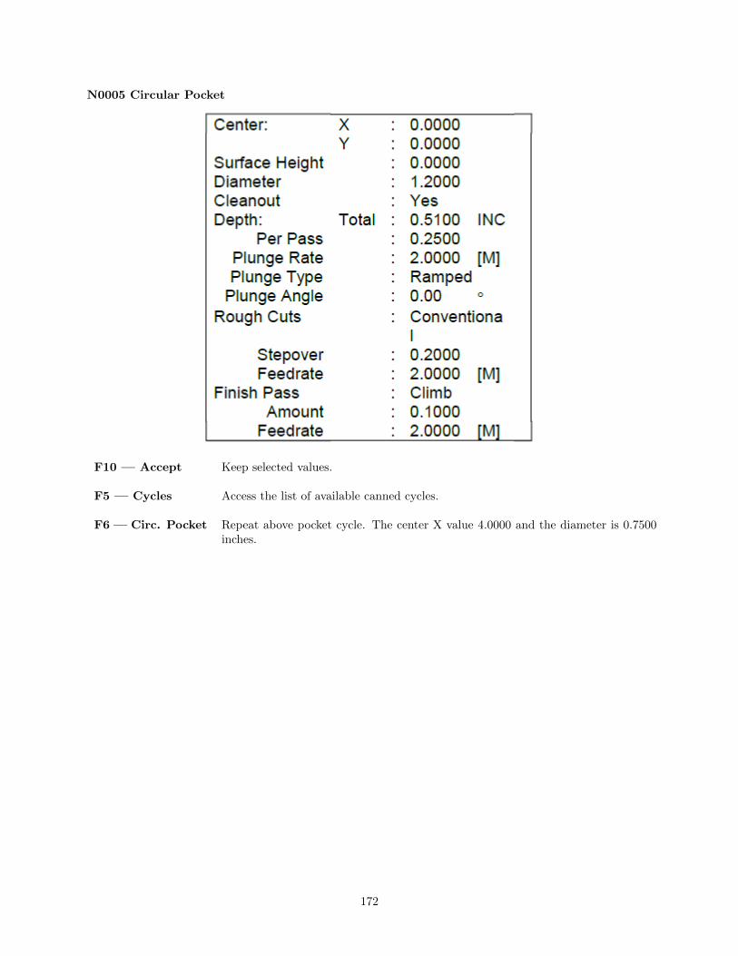
N0005 Circular Pocket
F10 — Accept Keep selected values.
F5 — Cycles Access the list of available canned cycles.
F6 — Circ. Pocket Repeat above pocket cycle. The center X value 4.0000 and the diameter is 0.7500inches.
172

N0006 Circular Pocket
F10 — Accept Keep selected values.
F5 — Cycles Access the list of available Canned Cycles.
F5—Rect. Pocket Cut the first rectangular pocket.
N0007 Rectangular Pocket
F10 — Accept Keep selected values.
173

F5 — Cycles Access the list of available Canned Cycles.
F5—Rect. Pocket Repeat above Pocket cycle. The center X value lies at 3.0000.
N0008 Rectangular Pocket
F10 — Accept Keep selected values.
F1 — Rapid Move to a location outside the part. The purpose of this move is to prepare to usecutter compensation on the tool.
N0009 Rapid Traverse
F10 — Accept Keep selected values.
F2 — Linear Need to do a zero length move to move the cutter down to zdepth before startingthe lead in move to the part. Not including the zero length move to z-depth wouldconfuse cutter comp. and cause the program to do weird things.
174
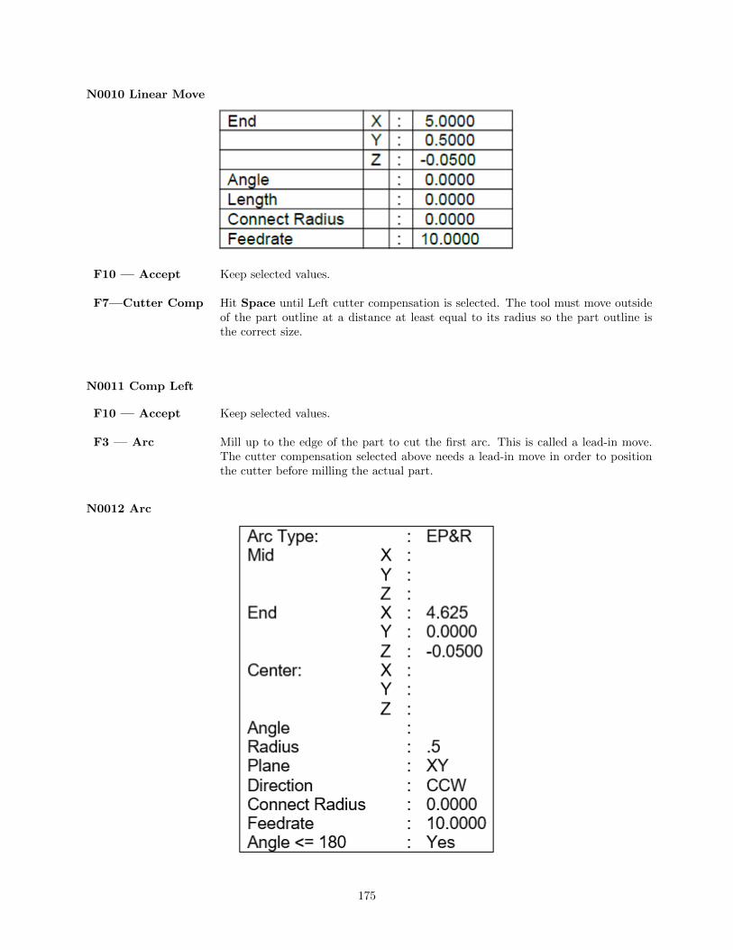
N0010 Linear Move
F10 — Accept Keep selected values.
F7—Cutter Comp Hit Space until Left cutter compensation is selected. The tool must move outsideof the part outline at a distance at least equal to its radius so the part outline isthe correct size.
N0011 Comp Left
F10 — Accept Keep selected values.
F3 — Arc Mill up to the edge of the part to cut the first arc. This is called a lead-in move.The cutter compensation selected above needs a lead-in move in order to positionthe cutter before milling the actual part.
N0012 Arc
175

You will see that after you enter in these values, the other points and arcs will be entered in automatically.
F10 — Accept Keep selected values.
F3 — Arc The first arc to be cut is labeled as ARC 1 in Figure 3 below. The start point,labeled P1, is the end point of the previous move. The end point of the arc will begenerated with Math Help. We will be using end point and radius (EP&R) arcs.
Figure 3 — Tangent point and arc reference.
176

N0013 Arc
F6 — Math Help We are trying to find end points for the arcs that make up the outside edge of thepart. Note: the main Math Help menu will list all available Math Help solvers.
F6 — Tangent ArcArc Arc
This scenario will generate tangent points P2 - P5 of Figure 3. Enter the values asshown below:
Arc Tangent Arcs:
Intercon will calculate the missing values for this scenario.
F2 — Next Soln Find scenario that corresponds to the actual arcs being milled. Observe Figure 4.Point T1 is the one needed.
177

ARROWS If necessary, move the block cursor to the Tangent 1 X field as shown above. Note:Use only ↑ and ↓. If you press the right arrow, press the left arrow to get back tothe Math Help fields.
F9 — Graphicon/off
Press to hide the graphical display and reveal the arc operation behind it.
→ (ARROW) Move the cursor to the arc operation. The solid block cursor on the left side of thescreen will be replaced by an outlined rectangle and the solid block will appear inthe arc operation on the right.
ARROWS Move the block cursor to the End X field of the arc operation. As before, use only↑ and ↓.
F8 — Copy >>> Transfer the tangent point T1 value for X into the end point X coordinate. Theactive fields on both sides of the screen advance automatically.
F8 — Copy >>> Transfer the tangent point T1 value for Y into the end point Y coordinate.
178

ARROWS Move down to the radius field and enter the radius of the arc labeled as ARC 1 inFigure 3. (This radius is 0.6250 in.).
F6 — Hide Math Hide Math Help temporarily. (We will return later to pick up the other tangentpoints.)
F8 — Graph Observe Figure 5. The graphics show a preview of the part up to this point. Thispreview can be used to detect problems that may occur if the part was cut now.
179

ESC/CANCEL Return to the editing screen.
F10 — Accept Keep selected values. The other arc values were calculated for you.
F3 — Arc The next arc to be cut is labeled as ARC 2 in Figure 3. The start point is labeledP2, the end point of the last arc.
N0014 Arc
↑↓ (UP/DOWN) Move down to the End X field. This selects End X as the destination of the MathHelp solution.
F6 — Math Help Re-display the Math Help values calculated for the last arc. The screen will looklike figure 6, below.
180

↑↓ (UP/DOWN) If necessary, move the block cursor to the Tangent 2 X field as shown above. Therectangle at End X shows that it will be the destination of the copy.
F8 — Copy >>> Transfer the tangent point T2 value for X into the end point X coordinate. Theactive fields on both sides of the screen advance automatically.
F8 — Copy >>> Transfer the tangent point T2 value for Y into the end point Y coordinate.
F6 — Hide Math Hide Math Help temporarily.
181
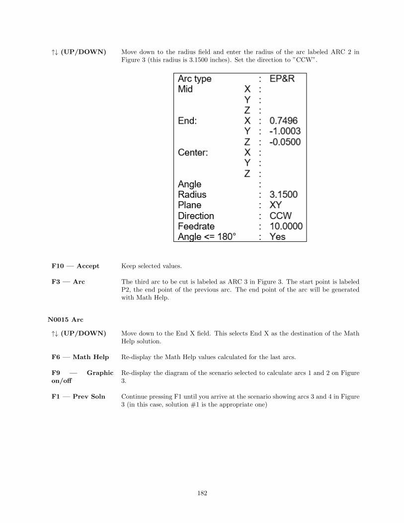
↑↓ (UP/DOWN) Move down to the radius field and enter the radius of the arc labeled ARC 2 inFigure 3 (this radius is 3.1500 inches). Set the direction to ”CCW”.
F10 — Accept Keep selected values.
F3 — Arc The third arc to be cut is labeled as ARC 3 in Figure 3. The start point is labeledP2, the end point of the previous arc. The end point of the arc will be generatedwith Math Help.
N0015 Arc
↑↓ (UP/DOWN) Move down to the End X field. This selects End X as the destination of the MathHelp solution.
F6 — Math Help Re-display the Math Help values calculated for the last arcs.
F9 — Graphicon/off
Re-display the diagram of the scenario selected to calculate arcs 1 and 2 on Figure3.
F1 — Prev Soln Continue pressing F1 until you arrive at the scenario showing arcs 3 and 4 in Figure3 (in this case, solution #1 is the appropriate one)
182

↑↓ (ARROWS) Press to highlight the needed tangent point X coordinate in Math Help. Tangentpoint T2 is the one you want this time.
← (ARROW) Press to remove the graphic display and move the cursor to the arc operation. (Thisshortcut saves you from pressing F9 — Graphic on/off to hide the graphics eachtime.) The solid block cursor on the left side of the screen will be replaced by anoutlined rectangle and the solid block will appear in the arc operation on the right.
↑↓ (ARROWS) Move the block cursor to the End X field of the arc operation.
F8 — Copy >>> Transfer the tangent point T2 value for X into the end point X coordinate. Theactive fields on both sides of the screen advance automatically.
F8 — Copy >>> Transfer the tangent point T2 value for Y into the end point Y coordinate.
183
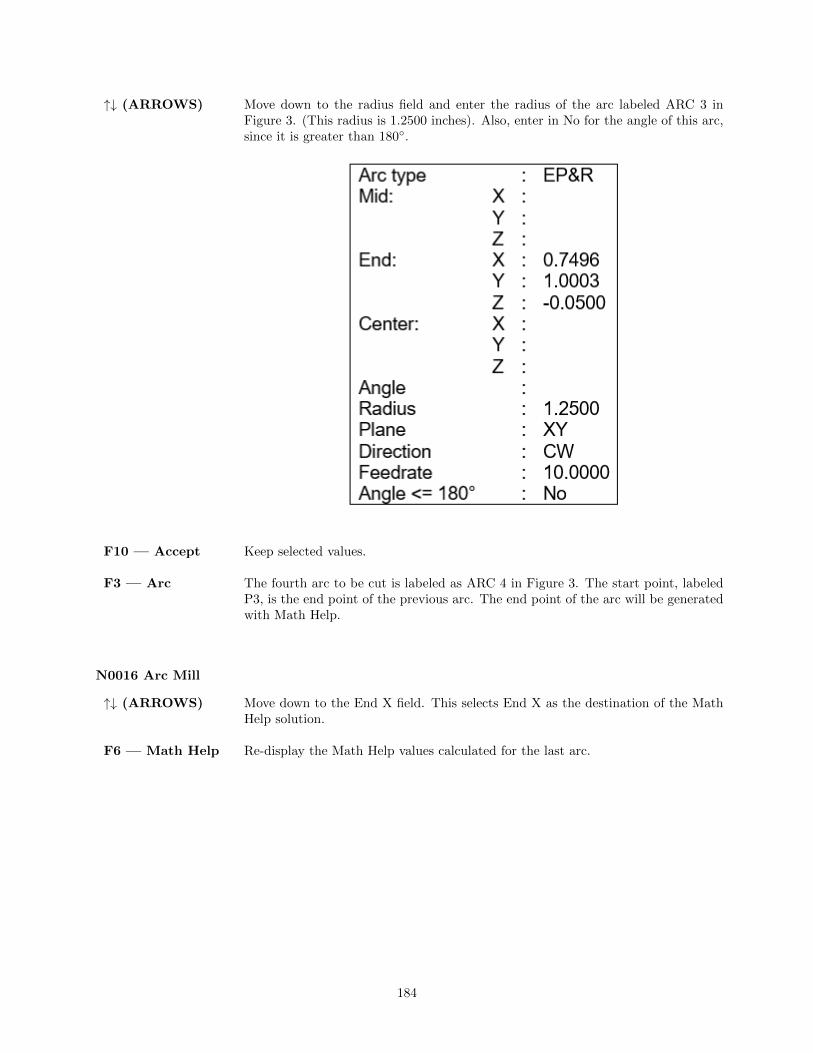
↑↓ (ARROWS) Move down to the radius field and enter the radius of the arc labeled ARC 3 inFigure 3. (This radius is 1.2500 inches). Also, enter in No for the angle of this arc,since it is greater than 180◦.
F10 — Accept Keep selected values.
F3 — Arc The fourth arc to be cut is labeled as ARC 4 in Figure 3. The start point, labeledP3, is the end point of the previous arc. The end point of the arc will be generatedwith Math Help.
N0016 Arc Mill
↑↓ (ARROWS) Move down to the End X field. This selects End X as the destination of the MathHelp solution.
F6 — Math Help Re-display the Math Help values calculated for the last arc.
184

↑↓ (UP/DOWN) Highlight the needed tangent point X. Tangent point T1 is the one you want thistime.
ARROWS If necessary, move the cursor to the arc operation and select the End X field.
F8 — Copy >>> Transfer the tangent point T1 value for X into the end point X coordinate. Theactive fields on both sides of the screen advance automatically.
F8 — Copy >>> Transfer the tangent point T1 value for Y into the end point Y coordinate.
F6 — Hide Math Hide Math Help.
185

ARROWS Move down to the radius field and enter the radius of the arc labeled ARC 4 inFigure 3. (This radius is 3.1500 inches). Be sure to set the direction to CCW.
F10 — Accept Keep selected values.
F3 — Arc Mill the arc labeled as ARC 5 in Figure 3 back to point P1.
186

N0017 Arc Mill
F10 — Accept Keep selected values.
F3 — Arc Move tool away from the edge of the part after the last arc.
N0018 Arc Mill
F10 — Accept Keep selected values.
187

F7 — CutterComp
Hit the SPACE bar until cutter compensation is turned ”Off”. It is no longerneeded.
N0019 Comp Off
F10 — Accept Keep selected values.
F1 — Rapid Move the tool away from the part. This is called a lead-out move. When cuttercompensation is turned off, the compensation is removed during the next move.This must be done to allow the CNC software to correct its position.
N0020 Rapid Traverse
F10 — Accept Keep selected values.
F9 — Subpgm Access the Subprogram screen.
F1 — Depth Re-peat
We programmed the outer contour of the part so that our tool would only penetratea small portion of the material per pass. We now want to repeat the outer contouroperations until the tool has cut the entire way through the material (the assumedmaterial thickness is 0.5 inches). The outer contour begins with the Plunge inoperation N0011 and ends with the Linear Mill in operation N0017.
N0021 Repeat To Depth
F10 — Accept Keep selected values.
F1 — Rapid Move the tool away from the part. This is called a lead-out move. When cuttercompensation is turned off, the compensation is removed during the next move.This must be done to allow the CNC software to correct its position.
188
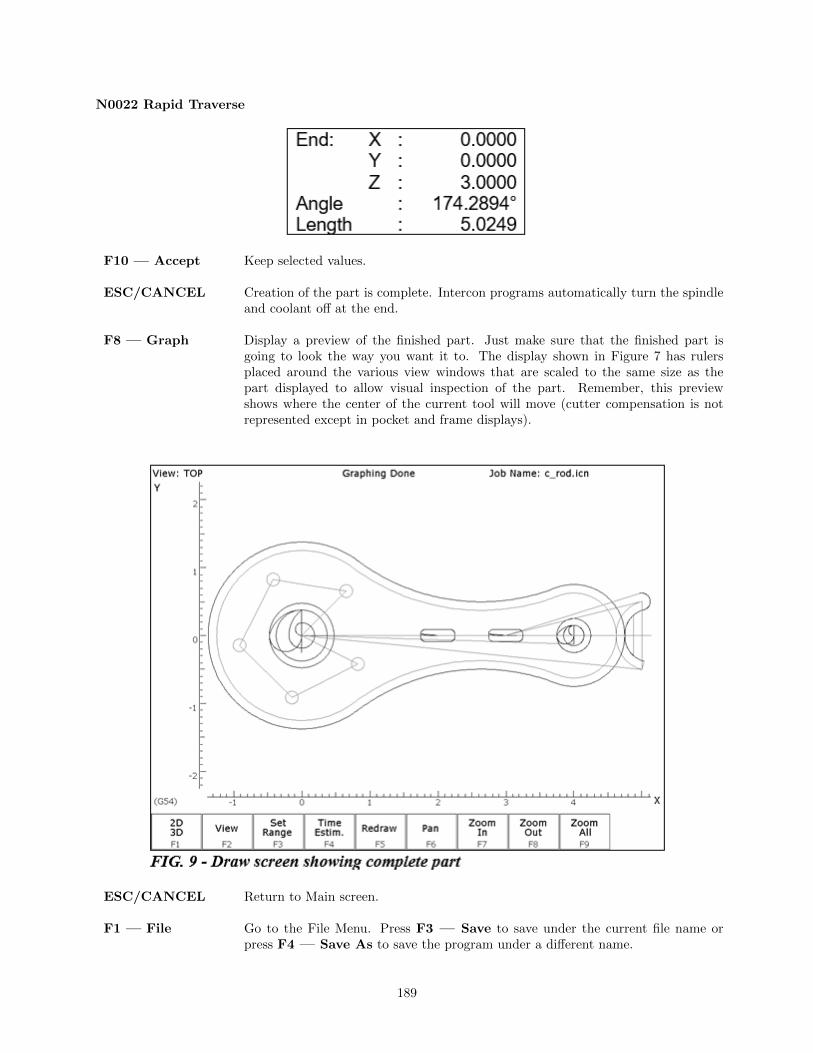
N0022 Rapid Traverse
F10 — Accept Keep selected values.
ESC/CANCEL Creation of the part is complete. Intercon programs automatically turn the spindleand coolant off at the end.
F8 — Graph Display a preview of the finished part. Just make sure that the finished part isgoing to look the way you want it to. The display shown in Figure 7 has rulersplaced around the various view windows that are scaled to the same size as thepart displayed to allow visual inspection of the part. Remember, this previewshows where the center of the current tool will move (cutter compensation is notrepresented except in pocket and frame displays).
ESC/CANCEL Return to Main screen.
F1 — File Go to the File Menu. Press F3 — Save to save under the current file name orpress F4 — Save As to save the program under a different name.
189

F10 — Post The CNC file needed to run this part on your mill will be generated at this time.The Intercon program displays the operation number of the part it is processing asit works through each operation in memory:
As it processes each operation, it checks for values that, if used, will cause incorrectcode to be produced. If such a value is found, a message will appear on the screenalerting you of the problem. For example, a problem with a rectangular pocketmay produce this message:
Changes to the part would then be required to allow proper code generation toproceed. If no problems are encountered during code generation, the followingmessage appears:
You are now at the main menu again.
Program Finished! You are now finished designing your part. In order to run your part, you now needto return to the CNC software.
10.12.2 Milling The Part
Now that the part has been programmed, it is time to mill it. Take your material and clamp it to the table.Remember that the clamps must be positioned such that they do not interfere with the tool as it cuts. Youmay choose to place the clamps around the edges of the material for the entire process and let the partdrop through upon completion, or you may wish to pause after milling the circular pockets and place clampsthrough the holes to prevent the part from moving. The second option decreases the chance of the partbeing marred because it moved during milling.
Now you need to set your XYZ reference points. Insert your longest tool in the quill and follow the procedurelisted below:
PRESS COMMENTS
JOG KEYS Jog the table so that your tool rests on the stock at the location that will representX0 and Y0.
F1 — Setup Enter the CNC software Setup screen. We are going to establish the part XYZ zeroat the current tool location.
F1 — Part Access the Part Setup options.
190

F10 — Set Set your X zero position at current tool location.
F1 — Next Axis Select the Y-axis next.
F10 — Set Set your Y zero position at current tool location.
F1 — Next Axis Select the Z-axis next.
F10 — Set Set your Z zero position at current tool location.
TOOL CHECK Moves the quill to the Z home position if the home position has been set. Movestool to Z+ limit switch and sets home position if not.
ESC/CANCEL Leave Part Setup screen.
F2 — Tool Access Tool Library Editor. This is the place where we want to measure the actualheights of our tools (since we could not set the actual values in Intercon).
F1 — Offset Lib. You need to make sure that the tool diameter and height offset values are thecorrect ones for the tools you are going to be using. Inspect the values for D001,H001, D002 and H002. D001 should be 0.1875, H1 should be 0.0000 (the two inchtool).
D002 should be 0.2500 and H002 should be -1.0000 (the one inch tool). If any ofthese values are incorrect, use the arrow keys to select the incorrect values. Enterthe new values in their places and press ENTER to accept them.
NOTE: The tool heights used above are merely example heights. In order to accurately measure the heightsof your tools, see the description of measuring tool heights in Chapter 5.
F10 — Save Keep the updated tool offset library values.
F2 — Tools Now you need to make sure that each tool uses the correct diameter and heightoffset values. Inspect the values for T001 and T002. T1 should use H001 and D001,while T002 should use H002 and D002. If any of these values are incorrect, use thearrow keys to select the incorrect values. Enter the new values in their places andpress ENTER to accept them. You may also select spindle and coolant settingsfor your tools here, or enter a short description of the tool.
F10 — Save Keep the updated Tool Library values.
ESC/CANCEL Leave Tool Setup. Return to the CNC software Setup Screen.
ESC/CANCEL Leave CNC software Setup. Return to the CNC software Main Screen.
CYCLE START The CYCLE START/START button is located on your jog panel. This key willcause the mill to begin cutting your part.
Tutorial Complete!
191

10.13 Measuring Tool Heights
The following is a brief description of the method used to measure tool height values (offsets). You will needto insert a reference tool into the quill before beginning. For more information also see chapter 5.
PRESS COMMENTS
F1 — Setup From the main screen enter the Setup.
F2 — Tool Enter tool screen.
F1 — Offset Lib. Enter the tool offsets screen.
JOG ARROWS You need to jog your reference tool down so it touches the top of some surface.
F1 — Z Ref Set your Z reference position. This is the value that appears on the DRO when thereference tool touches the top of the surface.
TOOL CHECK Move the quill up to the Z home position. Insert the first tool to measure.
ARROWS Select height offset which holds the height of the first tool.
JOG ARROWS Jog the tool down until it touches the same surface as did the reference tool.
F2 — Manual Record the height of the first tool.
Now repeat the last four steps above (from TOOL CHECK to F2 — Manual) foreach additional tool to measure.
F10 — Save Store modifications to offset library of your tools.
192

Chapter 11
CNC Program Codes
11.1 General
The next three chapters contain a description of the CNC program codes and parameters supported bythe M-Series Control. The M-Series Control has some G-codes and parameters that are modal, and somethat are ”one shots.” The G-codes and parameters that are modal will stay in effect until a new G-code orparameter is issued. One shots are effective for the current line only.
For example, a movement command of G1, which is modal, will remain in effect until a different movementcommand is issued, such as G0, G2, G3, etc.
11.2 Miscellaneous CNC Program Symbols
11.2.1 D — Tool Diameter Offset Number
D is used to select the Tool Diameter Offset from the offset library. The D code values are stored in theOffset Library. Tool Diameter Offsets can be specified anytime before Cutter Comp is turned on (G41 orG42). Once specified, the offset amount is stored and will only be changed when another D code is enteredtherefore, D is modal. The Tool Diameter Offset (D) can be placed on a line by itself or on a line with otherG-codes.
Example:
X0Y0F10 ;
G41 D2 ; Enables cutter comp left with diameter D2.
G1X0Y0 ;
X1Y1 .25 ; Cutter compensated moves
X2Y1.4 ;
G40 ; Cutter compensation off
G42 ; Enables cutter comp. right (still using D2)
11.2.2 E — Select Work Coordinate System
E1 through E18 select among the 18 work coordinate systems. For more information on work coordinatesystems see Work Coordinate Systems.
193

11.2.3 F — Feedrate
The F command is used to set the cutting feedrate. The feedrate is expressed in units/minute. The pro-grammed feedrate may be modified by the feedrate override knob (2 - 200% for DC systems and 2 – 100%for AC systems). The default feedrate is 3.0 units/minute. Units may be inches or millimeters.
Example:
G90 G1 X1.0 F50 ; linear mill to X1 at 50 units/minute
11.2.4 H — Tool Length Offset Number
H is used to select the Tool Length Offset Number. The H code offset amounts are stored in the file OffsetLibrary. Tool Length Offsets can be specified anytime before a G43 or G44 is issued. Once specified theoffset amount is stored and will only be changed when another H code is entered therefore, H is modal. TheTool Length Offset (H) can be placed on a line by itself or on a line with other G-codes. H00 is always a 0.0length offset.
Example:
H1 ; Selects offset corresponding to H1.
G43 Z3 ; Moves to Z3 using H1 offset.
G1X0Y1 ;
H3 ; Selects offset corresponding to H3.
X1Y1 .25 ;
G0H5 ; Selects offset corresponding to H5.
11.2.5 N — Block Number
Block numbers are used to identify CNC program lines. Block numbers are optional, but can be used asthe destinations of GOTO statements (see Advanced Macro Statements) and targets of the Search Func-tion (See Main Screen Search option in Chapter 3). Block numbers also can make reading the NC files easier.
Example:
N1 G90 G17 M25
N2 G0 X0 Y0 Z0
11.2.6 O — Program Number
The O program number allows you to identify your program with a certain number. However, if the specifiedprogram number is 9100-9999, the G-codes from the O number through the next M99 will be extracted (butnot executed) and placed in a separate subprogram/macro file named Oxxxx.cnc, where xxxx is the specifiedprogram number. This separate file can later be called with M98 or G65.
Example:
194

O1521
N1 G90 G17 M25
N2 G0 X0 Y0 Z0
11.2.7 P — Parameter
P can correspond to Dwell Time, subprogram number, or a general parameter in canned cycles. This is usedas a variable for any of those values in the NC file.
Example:
G4 P1.32 ; Pause execution for 1.32 seconds
G10 P73 R.1 ; Set parameter #73 (G73 retract) to .1 inches
11.2.8 Q — Parameter
Q is used as a depth parameter in canned drilling cycles.
Example:
G73 X1.5 Y2.0 Z-.75 R.25 Q.25 F5 ; Q Sets the depth cut at .25
11.2.9 R — Radius, Return Point, Parameter
R can represent the radius, a return point, or a general parameter. This is used as a variable for any of thosevalues in the NC file. R is similar to the P parameter.
Example:
G10 D5 R.5 ; sets tool diameter #5 to 0.5" in the offset library
G81 X0 Y0 Z-.5 R.1 F15 ; drill to Z-.5 with return height of .1
11.2.10 S — Spindle Speed Setting
Specifying a spindle speed causes the automatic spindle speed setting to be immediately updated. Settingthe spindle speed does not cause the spindle to start. The maximum spindle speed is used to compute theoutput value to the spindle speed control circuit.
Example:
S1400 M3 ; Starts the spindle CW at 1400 RPM
NOTE: The Spindle Speed is used in conjunction with the maximum spindle speed to determine the actualspindle speed output to the PLC. Also, this only works when a VFD (Variable Frequency Drive) spindledrive is connected.
195

11.2.11 T — Select Tool
Prompts the operator to insert the proper tool or change tools, when M6 is encountered.
Example:
T1 M6 ; Prompt operator to load tool number 1
T2 ; no action
G0X0Y0 ; move to X0 Y0
M6 ; prompt operator to load tool number 2
11.2.12 : — Visible Comment Identifier
The colon (:) is used to indicate the start of a comment line within a CNC program. The colon must be thefirst character on the line.
Example:
: select absolute positioning
G90
: XY plane
G17
:Visible comments will be displayed on screen with the G-codes.
11.2.13 ; — Internal Comment Identifier
The semicolon (;) is used to indicate the start of an internal comment within a CNC program line. All char-acters after the semicolon are ignored when the program is run. Internal comments are used to documentNC programs or temporarily omit the remainder of a line.
Example:
G90 ; select absolute positioning
G17 ; XY plane
G1 X1 Y1 F10
G0 ; X0 Y0 ; G0 selected with no movement
11.2.14 [ ] — Numerical Expression
The left bracket ’[’ and right bracket ’]’ are used to delimit a numerical expression. Numerical expressionscan contain floating-point numbers or user and system variables in combination with mathematical operatorsand functions. The left parenthesis ’(’ or bracket ’[’ and right parenthesis ’)’ or bracket ’]’ can be used be-tween the first left bracket and last right bracket to force operator precedence or associatively. A bracketednumerical expression can be used anywhere a number would be used. Comparison operators (’eq’, ’ne’, etc.)have built in rounding specified by parameter 144. Without this rounding, ’eq’ would usually return ”false”when comparing two numbers calculated in different ways. Comparison operators and logical operators (’ !’,’&&’, ’||’) return 1.0 for ”true” and 0.0 for ”false”.
The mathematical operators and functions are:
196

+ Addition (or unary positive)
- Subtraction (or unary negative)
* Multiplication
/ Division
^ Exponentiation
Mod or % Modulo (remainder of a division)
abs Absolute value
sin Sine (degrees)
cos Cosine (degrees)
tan Tangent (degrees)
sqrt Square root
asin Arc Sine (degrees)
acos Arc Cosine (degrees)
atan Arc Tangent (degrees)
fix Floor (round down to nearest integer)
fup Ceiling (round up to nearest integer)
# Variable access
eq or == Equals
ne or != Not equals
ge or >= Greater than or equals
gt or > Greater than
le or <= Less than or equals
lt or < Less than
not or ! Logical NOT
&& Logical AND
|| Logical OR
and Bit -wise AND
xor Bit -wise exclusive OR
or Bit -wise OR
~ Bit -wise complement
Example:
G91 X[13/64] Z[1+3/8] ; move the X axis 13/64 (0.2031) units
; and the Z axis 1 3/8 (1.375) units incrementally
X[SQRT[ABS[SIN [#101] - COS [#102]]]] ; Move X as a function of #101 and #102
11.2.15 $ — ASCII Code Substitution
The ’$’ symbol followed by an ASCII code is an alternate way of specifying a letter. Only ASCII codes 65 – 90(’A’ - ’Z’) are valid. This substitution can be used where a letter command or axis label is normally specified.
Example:
G0 $88 2.0 ; Rapid move X to 2.0 ( Equivalent to G0 X2.0 )
$71 0 $[88+2] 3.0 ; Rapid move Z to 3.0 ( Equivalent to G0 Z3.0 )
M26 /$90 ; Set Z home ( Equivalent to M26 /Z )
11.2.16 #, = — User or System Variable reference
The ’#’ character is used to reference a macro or a user or system variable. For variables that can be written,the ’=’ is used to assign to them. General purpose user variables are #100 to #149 and #29000 to #31999.
197

Index Description Returns R\W1-3 Macro arguments A-C
The floating point value ifdefined by a G65 call, 0.0otherwise. These can be used asprivate, local variables in anyprogram or subprogram exceptin custom macro M functions.In custom macro M functions,the macro arguments are passedin by reference.
R/W4-6 Macro arguments I-K (1st set) R/W7-9 Macro arguments D-F or 2nd set of I-K R/W10 3rd I (G is invalid) R/W11 Macro argument H or 3rd J R/W12 3rd K (L is invalid) R/W13 Macro argument M or 4th I R/W14 4th J (N is invalid) R/W15 4th K (O is invalid) R/W16 5th I (P is invalid) R/W17-18 Macro argument Q-R or 5th J-K R/W19-21 Macro arguments S,T,U or 6th set of I-K R/W22-24 Macro arguments V,W,X or 7th set of I-K R/W25-27 Macro arguments Y,Z or 8th set of I-K R/W28-30 9th set of I-K R/W31-33 10th set of I-K R/W
100 - 149 User variablesFloating-point value. Initializedto 0.0 at start of job processing
R/W
150 - 159 Nonvolatile user variablesFloating-point value saved incncm.job.xml file.
R/W
300-399User string variables. These variables re-tain their values until the CNC software isexited
String Literal R/W
2400, 2401-2418 Active WCS, WCS #1-18 CSR angles
Floating point value
R/W2500, 2501-2518 Active WCS, WCS #1-18 Axis 1 values R/W2600, 2601-2618 Active WCS, WCS #1-18 Axis 2 values R/W2700, 2701-2718 Active WCS, WCS #1-18 Axis 3 values R/W2800, 2801-2818 Active WCS, WCS #1-18 Axis 4 values R/W2900, 2901-2918 Active WCS, WCS #1-18 Axis 5 values R/W3000, 3001-3018 Active WCS, WCS #1-18 Axis 6 values R/W3100, 3101-3118 Active WCS, WCS #1-18 Axis 7 values R/W3200, 3201-3218 Active WCS, WCS #1-18 Axis 8 values R/W3901 Parts Cut (Part #) R/W3902 Parts Required (Part Cnt) R/W4001 Move mode 0.0 (rapid) or 1.0 (feed) R4003 Positioning mode 90.0 (abs) or 91.0 (inc) R4006 Units of measure 20.0 (inches) or 21.0 (metric) R4014 WCS 54.0-71.0 (WCS#1-18) R4109 Feedrate (F)
Floating point valueR
4119 Spindle Speed (S) R4120 Tool Number (T) R4121 Current height offset number (H) R
4122Current diameter offset number (D, millonly)
R
4201 Job processing state 0 = normal, 1 = graph R
4202 Job Search mode
0 = search mode off1 = searching for line number2 = searching for block numberN3 = searching for Tool number4 = resuming job
R
198

Index Description Returns R\W4203 Tool in spindle R
5021-5028Machine Position (axis 1 = 5021, axis 2 =5022, etc.) Floating point value
R
5041-5048Current Position (axis 1 = 5041, axis 2 =5042, etc.)
R
9000-9399 Parameter values 0 - 399 See Machine Parameters R9900-9999 Parameter values 900 - 999 See Machine Parameters R10000 Mill: Height offset amount, active H Floating point value R/W10001-10200 Mill: Height offset amount, H001 – H200 Floating point value R/W11000 Mill: Diameter offset amount, active D Floating point value R/W
11001-11200Mill: Diameter offset amount, D001 –D200
Floating point value R/W
12000 Mill: Tool H number, active tool (T) 0 - 200 R/W12001-12200 Mill: Tool H number, tools 1 - 200 0 - 200 R/W13000 Mill: Tool D number, active tool (T) 0 - 200 R/W13001-13200 Mill: Tool D number, tools 1 - 200 0 - 200 R/W14000 Mill: Tool coolant, active tool (T) 7, 8, 9 R/W14001-14200 Mill: Tool coolant, tools 1 – 200 7, 8, 9 R/W
15000Mill: Tool spindle direction, active tool(T)
3, 4, 5 R/W
15001-15200 Mill: Tool spindle direction, tools 1 - 200 3, 4, 5 R/W16000 Mill: Tool spindle speed, active tool (T) Floating point value R/W16001-16200 Mill: Tool spindle speed, tools 1 - 200 Floating point value R/W17000 Mill: Tool bin number, active tool (T) Floating point value R/W17001-17200 Mill: Tool bin number, tools 1 - 200 Floating point value R/W18000 Mill: Tool putback, active tool (T) Floating point value R/W18001-18200 Mill: Tool putback, tools 1 – 200 Floating point value R/W19000 Tool Life Data: Tool T1 Tool Type 0 = Drill, 1 = End Mill R/W19001 Tool Life Data: Tool T1 Total Life Floating point value R/W19002 Tool Life Data: Tool T1 Used Life Floating point value R/W
19003 Tool Life Data: Tool T1 Units0 = Cycles, 1 = Inch/mm dis-tance
R/W
19004 Tool Life Data: Tool T1 Update Mode 0 = Manual, 1 = Auto R/W19005-19009 Tool Life Data for Tool T2 see 19000-19004 above R/W19010-19014 Tool Life Data for Tool T3 see above R/W19015-19999 Tool Life Data for Tools T4 through T200 see above R/W20001-20008 max rate for axes 1-8 R20101-20108 label for axes 1-8 R20201-20208 slow jog for axes 1-8 R20301-20308 fast jog for axes 1-8 R20401-20408 screw pitch for axes 1-8 R/W20501-20508 lash comp for axes 1-8 R20601-20608 counts per unit for axes 1-8 R20701-20708 accel time for axes 1-8 R20801-20808 deadstart velocity for axes 1-8 R20901-20908 delta vmax for axes 1-8 R21001-21008 counts per turn for axes 1-8 R21101-21108 minus limit for axes 1-8 R21201-21208 plus limit for axes 1-8 R21301-21308 minus home for axes 1-8 R21401-21408 plus home for axes 1-8 R
199

Index Description Returns R\W21501-21508 reversed for axes 1-8 R21601-21608 laser comp for axes 1-8 R21701-21708 proportional for axes 1-8 R21801-21808 integration limit for axes 1-8 R21901-21908 kg for axes 1-8 R22001-22008 integral for axes 1-8 R22101-22108 kv1 for axes 1-8 R22201-22208 derivative for axes 1-8 R22301-22308 ka for axes 1-8 R22401-22408 num motor poles for axes 1-8 R22501-22508 drive current for axes 1-8 R22601-22608 drive offset angle for axes 1-8 R22701-22708 pwm kp for axes 1-8 R22801-22808 pwm ki for axes 1-8 R22901-22908 pwm kd for axes 1-8 R23001-23008 abrupt kp for axes 1-8 R23101-23108 feed forward kp for axes 1-8 R23201-23208 max error (PID) for axes 1-8 R23301-23308 min error (PID) for axes 1-8 R23401-23408 at index pulse for axes 1-8 R23501-23508 travel minus for axes 1-8 R/W23601-23608 travel plus for axes 1-8 R/W23701-23708 axis home set for axes 1-8 R
23801-23808abs position (in encoder counts) for axes1-8
R
23901-23908 PID out for axes 1-8 R24001-24008 reference set for axes 1-8 R24101-24108 Axis reference value for axes 1-8 R24201-24208 tilt table level offsets for axes 1-8 R24301-24308 dsp positions for axes 1-8 R
24401-24408abs position (in encoder counts) for axes1-8
R
24501-24508dsp positon in local cooridinates for axes1-8
R
24601-24608 local probing +limit position for axes 1-8 R24701-24708 local probing -limit position for axes 1-8 R
24801-24808probe stylus compensation amount foraxes 1-8
R
24901-24908 servo controlled axis indicator for axes 1-8 0 = no, 1 = yes R25000 DRO display units R25001 default units of measure R25002 PLC type R25003 console type R25004 jog panel optional R25005 min spin high R25006 max spin high R25007 home at powerup R25008 screen blank time R
25009Displayed / Calculated spindle speed. Ifparameter 78 =1 and spindle encoder ismounted.
R
200

Index Description Returns R\W25010 current spindle position (in counts) R25011 dsp time (in seconds) R25012 time (in seconds) R25013 clear max/min PID errors R25014 software type (Mill/Lathe) R25015 feedrate override R25016 spindle override R
25017 OSWindows/LINUX = 2; other OS= 1.0
R
25018 CNC series number (11 for CNC11) R25019 Software version number R25020 Software Beta revision number R25021 Digitizing boundary hit hit = 1, not hit = 0 R25022 last M115/116/125/126 probe trip 1 = tripped, 0 = not tripped R
25023 Drive type0 = Standard, 1 = Legacy DC,2 = Legacy AC
R
25101-25108Encoder counts away from index pulse foraxes 1-8
Counts away from index pulse.Values less than 0 means that in-dex pulse is not detected yet.
R
26001-26008dsp mechanical machine positions for axes1-8
R
26101-26108 dsp mechanical local positions for axes 1-8 R26201-26208 local + travel limit position for axes 1-8 R26301-26308 local - travel limit position for axes 1-8 R26401-26404 Axis 1 reference points 1-4 R26501-26504 Axis 2 reference points 1-4 R26601-26604 Axis 3 reference points 1-4 R26701-26704 Axis 4 reference points 1-4 R26801-26804 Axis 5 reference points 1-4 R26901-26904 Axis 6 reference points 1-4 R27001-27004 Axis 7 reference points 1-4 R27101-27104 Axis 8 reference points 1-4 R
27201-27208ACDC drive estimated brake wattage foraxes 1-8
R
27301-27308 Real motor encoder positions for axes 1-8
Motor encoder positions that ac-counts for lash, MPG, and scaleoffsets. (Note that these can bedifferent from what is displayedas Abs Pos in the PID menu.)
R
27401-27408 Scale encoder positions for axes 1-8 R
29000-31999User variables. These variables retaintheir values until the CNC software is ex-ited.
Floating point value R/W
32000-34999 Reserved for internal use. DO NOT USE Floating point value R/W50001-51312 PLC Inputs 1-1312 Jog Panel is on INP1057-1312 R60001-61312 PLC Outputs 1-1312 Jog Panel is on OUT1057-1312 R70001-71024 PLC Memory Bits 1-1024 R80001-89999 Reserved R90001-90064 Timer 1-64 status bits R91001-91064 Reserved R92001-92064 Reserved R
201

Index Description Returns R\W93001-93256 Stage 1-256 status bits R94001-94256 Fast Stage 1-256 status bits R95001-95256 Reserved R96001-96044 W1-W44 (32-bit signed integers) R97001-97022* DW1-DW22 (64-bit signed integers) R98001-98044 FW1-FW44 (32-bit floats) R99001-99022 DFW1-DFW22 (64-bit floats) R
* Since user or system variables are turned into (double) floating point values when referenced in an M- orG-code program, the 64-bit integer values lose precision when they exceed 253 (9,007,199,254,740,992).
Example:
#100 = #5041 ; set user variable #100 to the X axis current position
G90 X[#5041+1+7/32] ; move the X axis 1 7/32 units (1.2188) incrementally
#2501 = #5021 ; set WCS#1 X value to the current X position
#2703=[#2703+1/8] ; add 1/8 units (.125) to the WCS#3 Z value
; Subroutine parameter and local variable access.
G1 X#A Y#B Z#C F#F ; move to the coordinates passed as parameters
#[Q] = #F * .10 ; Assign local variable #Q to 10% of #F
#17 = #7 * .10 ; Same statement as previous using number references.
#[C] = 0.05 ; Reassign #C. (Value passed as parameter is lost.)
11.3 Advanced Macro StatementsBranching and conditional execution are extremely powerful tools that,combined with access to system variables, allow you to do many things thatwould otherwise be impossible. Nevertheless, using branching and condi-tional execution can introduce undesirable and even unpredictable behav-ior into your programs. Undesirable effects can occur simply by graphing aprogram. The least of these undesirable effects could be entering an endlessloop, failing to draw anything, or wiping out all the information in yourtool library or WCS settings. It is your responsibility to make sure thatundesirable things do not happen in your programs. You must monitor thejob processing and search modes in your program, if necessary, and takeappropriate action. Until you are confident of the actions of your program,you should step through it one block at a time to confirm your programlogic.
11.3.1 GOTO — Branch Execution
To branch to another line within the same program or subprogram, use the statement:
GOTO <expression>
where <expression> is any expression that evaluates to a valid block number in the program. GOTO causesan immediate branch to the specified destination. Program codes preceding a GOTO on the same line willbe executed normally. Any program codes following GOTO on the same line will cause an error.
202

If fast branching is disabled (parameter 145 = 0) then the CNC software searches forward in the program forthe first matching block number and resumes searching, if necessary from the top of the program. For thisreason when fast branching is disabled, backward branches take longer than forward branches and backwardbranch times depend on the total program size. If the program is sufficiently large, use of the GOTOstatement could introduce temporary pauses.
When fast branching is enabled (parameter 145 = 1) then the CNC software remembers the locations of blocknumbers as it finds them during program execution. Backward branches always take place immediately. Thefirst forward branch to a block not yet encountered will take additional time as the CNC software searchesforward for the block number; however, subsequent forward branches to that block number will take placeimmediately. The trade-off for using fast branching is that all line numbers at a given level of program orsubprogram must be unique and programs will use more memory (approximately 16kilobytes of memory forevery 1000 block numbers in the program.)
11.3.2 IF THEN ELSE — Conditional Execution
Program symbols, G-codes, M codes and GOTO commands may be executed conditionally using the IFstatement. The general form of the IF statement is:
IF <expression> THEN <execute if true> ELSE <execute if false>
where <expression> is any valid expression, <execute if true> is one or more program codes to executeif <expression> evaluates to ”true” (non-zero) and <execute if false> is one or more program codes toexecute if <expression> evaluates to ”false” (zero). All parts of the IF statement must appear on the sameline. The ”ELSE <execute if false>” part of the statement is optional and may be omitted. The ”THEN”may be omitted; however, <expression> must be enclosed in brackets ([ ]). The IF statement may followother program codes on the same line. Compound conditionals are possible but they cannot be nested. Thefirst THEN always pairs with the first IF. ELSE always pairs with the first <expression> that evaluates to”false”. All program codes executed are executed as part of the same block.
Example:
; Branch to N200 if machine position is okay , otherwise go to N300
N100 IF #5041 LE 5.0 THEN GOTO 200 ELSE GOTO 300
; Force subprogram parameter #D to be within range.
IF [#D LE 0.005] #[D] = 0.005
; Compound conditionals
IF [#A LE 0.0] GOTO 100 ELSE IF [#A LE 2.5] GOTO 200 ELSE GOTO 300
IF [#A GT 0.0] IF [#D/#A GE 0.0] #[C] = SQRT[#D/#A]
11.3.3 INPUT — Prompt Operator For Input
The INPUT macro prompts the operator for numeric input. The general form of the INPUT statement is:
INPUT ”<prompt>” <variable>
Where <prompt> is the message prompt for the operator and <variable> is the variable in which to storethe input. The CNC software will display a dialog with the given prompt and space for the operator response.The operator may enter any numeric expression (see above) including variables as a response. The operatormust press CYCLE START or Alt-S to dismiss the dialog. Pressing ESC will cancel the job.
The CNC software parses well ahead of the current execution to maximize throughput and efficiency. Forthis reason, an INPUT macro may prompt the operator for input immediately even though the INPUTmacro is located in the middle or near the end of the job. Parsing pauses while the dialog is displayed.
203

Any statements parsed prior to the INPUT macro will have been queued and will continue to execute inthe background while the prompt is displayed. Job processing will pause only if all queued statements havebeen executed before the operator supplies a response.
INPUT macros will not graph. If you must graph the job, first set the input variable to a default value anduse a conditional to execute the INPUT only if the job is being run normally.
Use search mode cautiously with INPUT macros. To have search work properly, you may have to supplyexactly the same input during the search as you did during the last actual run.
Example:
; Ask operator for pocket depth. Store result in #101
; Note: this will not graph.
INPUT "Enter pocket depth" #101
; Allow job with INPUT statements to be graphed.
#101 = 0.5; Supply a default value for graphing
; Ask for operator input only if not graphing.
IF NOT #4201 THEN INPUT "Enter pocket depth" #101
11.3.4 DEFINE — Text Aliases
You can define your own text aliases using angle brackets (<>). This is a pure text replacement tool (withone exception — any text found after a semicolon (’;’) will be ignored as a comment), but can be quiteuseful.
To define an alias in your G-code program, use the word DEFINE followed by the name of your alias (inangled brackets) followed by the text it will be replacing.
For example, consider the following G-code program:
G17 G90 F25
G00 X1.0 Y1.0 Z0.0
G02 X2.0 Y2.0 Z0.0 R-1.0
Using the angle bracket defines, we could write:
; Definitions begin here
DEFINE <XY_PLANE > G17
DEFINE <ABSOLUTE_POSITIONING > G90
DEFINE <FEEDRATE > F
DEFINE <RAPID_POSITIONING > G0
DEFINE <START_POSITION > X1.0 Y1.0 Z0.0
DEFINE <CLOCKWISE_ARC > G02
DEFINE <END_POSITION > X2.0 Y2.0 Z0.0
DEFINE <BIG_ARC_RADIUS > R-1.0
; Actual job begins below
<XY_PLANE > <ABSOLUTE_POSITIONING > <FEEDRATE >25
204

<RAPID_POSITIONING > <START_POSITION >
<CLOCKWISE_ARC > <END_POSITION > <BIG_ARC_RADIUS >
This can make your G-code programs more readable and understandable.
205

Chapter 12
CNC Program Codes: G-Codes
G-Code Group DescriptionG00 * A Rapid PositioningG01 A Linear InterpolationG02 A Circular or Helical Interpolation CWG03 A Circular or Helical Interpolation CCWG04 B DwellG09 B Decelerate and Stop (formerly known as Exact Stop)G10 B Parameter SettingG17 * C Circular Interpolation Plane Selection XYG18 C Circular Interpolation Plane Selection ZXG19 C Circular Interpolation Plane Selection YZG20 * K Select Inch UnitsG21 K Select Metric UnitsG22 O Work envelope onG23 * O Work envelope offG28 B Return to Reference PointG29 B Return from Reference PointG30 B Return to Secondary Reference PointG40 * D Cutter Compensation CancelG41 D Cutter Compensation LeftG42 D Cutter Compensation RightG43 E Tool Length Compensation (+)G43.3 E Tool Length Compensation (+) with Axis Tilt CompensationG43.4 E Rotary Tool Center Point (with G43.3 compensation)G44 E Tool Length Compensation (-)G49 * E Tool Length Compensation CancelG50 * M Scaling/Mirroring OffG51 M Scaling/Mirroring OnG52 B Offset Local Coordinate System OriginG53 B Rapid Position in Machine CoordinatesG54 L Select Work Coordinate System #1G55 L Select Work Coordinate System #2G56 L Select Work Coordinate System #3G57 L Select Work Coordinate System #4G58 L Select Work Coordinate System #5G59 L Select Work Coordinate System #6
206
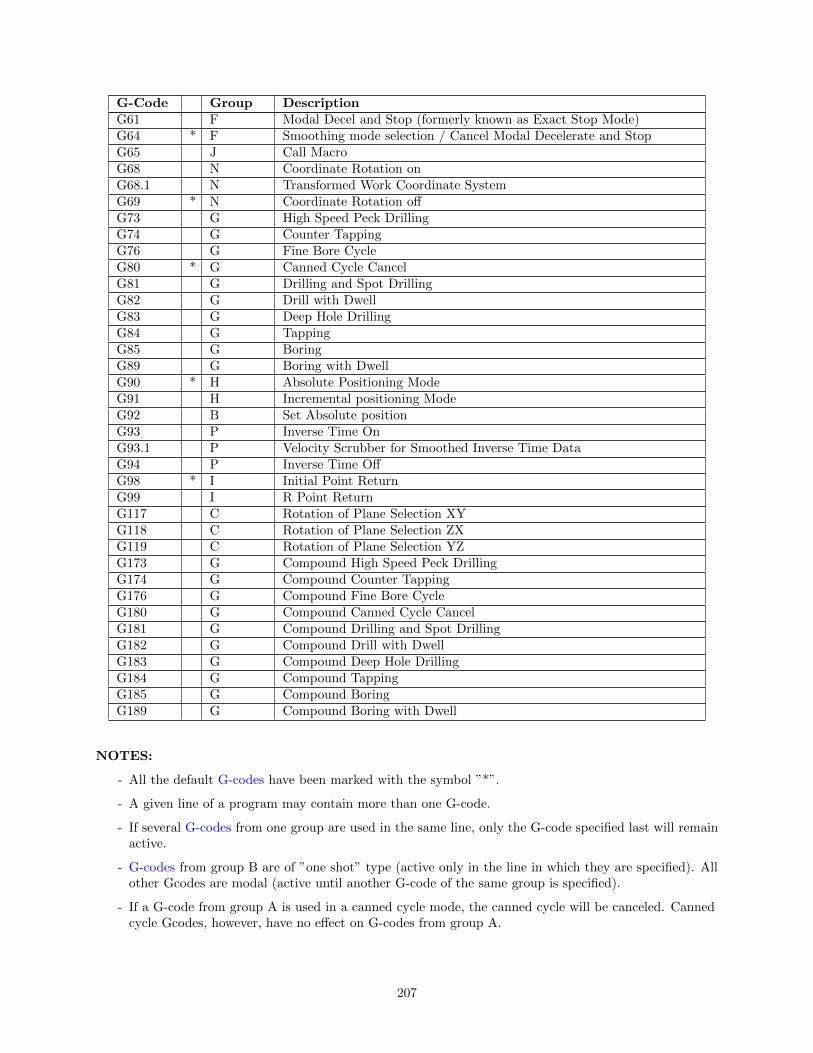
G-Code Group DescriptionG61 F Modal Decel and Stop (formerly known as Exact Stop Mode)G64 * F Smoothing mode selection / Cancel Modal Decelerate and StopG65 J Call MacroG68 N Coordinate Rotation onG68.1 N Transformed Work Coordinate SystemG69 * N Coordinate Rotation offG73 G High Speed Peck DrillingG74 G Counter TappingG76 G Fine Bore CycleG80 * G Canned Cycle CancelG81 G Drilling and Spot DrillingG82 G Drill with DwellG83 G Deep Hole DrillingG84 G TappingG85 G BoringG89 G Boring with DwellG90 * H Absolute Positioning ModeG91 H Incremental positioning ModeG92 B Set Absolute positionG93 P Inverse Time OnG93.1 P Velocity Scrubber for Smoothed Inverse Time DataG94 P Inverse Time OffG98 * I Initial Point ReturnG99 I R Point ReturnG117 C Rotation of Plane Selection XYG118 C Rotation of Plane Selection ZXG119 C Rotation of Plane Selection YZG173 G Compound High Speed Peck DrillingG174 G Compound Counter TappingG176 G Compound Fine Bore CycleG180 G Compound Canned Cycle CancelG181 G Compound Drilling and Spot DrillingG182 G Compound Drill with DwellG183 G Compound Deep Hole DrillingG184 G Compound TappingG185 G Compound BoringG189 G Compound Boring with Dwell
NOTES:
- All the default G-codes have been marked with the symbol ”*”.
- A given line of a program may contain more than one G-code.
- If several G-codes from one group are used in the same line, only the G-code specified last will remainactive.
- G-codes from group B are of ”one shot” type (active only in the line in which they are specified). Allother Gcodes are modal (active until another G-code of the same group is specified).
- If a G-code from group A is used in a canned cycle mode, the canned cycle will be canceled. Cannedcycle Gcodes, however, have no effect on G-codes from group A.
207

12.1 G00 - Rapid Positioning
G0 moves to the specified position at the maximum motor rate. The coordinates maybe either absolute positions (G90) or incremental positions (G91). G0 is modal andremains in effect until another positioning mode (G1, G2, G3 etc.) is commanded.G0 is the default-positioning mode.
When the Z axis is commanded to move in the + direction, the Z axis will move up to its new positionfirst, then the other axes will move to their new position along a straight line.
When the Z axis is commanded to move in the - direction, all axes but the Z axis will move to their newposition along a straight line, then the Z axis will move down to its new position.
Example:
G0 X0.0 Y0.0 Z0.0 ; Rapid move to X0, Y0, Z0
The feedrate override knob has no effect on G0 moves unless rapidoverride is turned ON.
12.2 G01 - Linear Interpolation
G1 moves to the specified position at the programmed feedrate. The coordinates maybe either absolute positions (G90) or incremental positions (G91). The movement willbe along a straight line. G1 is modal and remains in effect until another positioningmode (G0, G2, G3 etc.) is commanded.
Example:
G01 X2 Y3 Z4 W5 F10 ; Linear move to X2, Y3, Z4, W5 at a 10in/minG91 X6 Y7 ; Linear move to X8, Y10Z3 W4 F20 ; Linear move to Z7, W9 at 20in/min (G91 is modal)
12.3 G02 & G03 - Circular or Helical Interpolation
G2 moves in a clockwise circular motion, and G3 moves in a counterclockwise circularmotion. This clockwise and counterclockwise motion is relative to your point of view,however. See the diagram below. The X, Y or Z position specified in the G2 or G3command is the end position of the arc, and may be an absolute position (G90) or anincremental position (G91). G2 and G3 are modal and remain in effect until anotherpositioning mode (G0, G1, etc.) is commanded.
208

*Note: When using G18, the G2 command moves in a counterclockwise direction in the XZ plane.
The axes included in the currently selected circular plane (G17, G18, or G19) will move in a circularmotion. Any other axes specified will move along a straight line (helical movement). The programmedfeedrate is used for the interpolated motion along the movement of all axes.
Helical and circular motion can be programmed in two different ways: specifying the final point and theradius of the arc, or specifying the final point and the parameters I, J, K (center point of the arc asincremental values from the start position).
*Note: For closed circles (arc of 360 degrees), use method 2: specify final point and parameters I, J andK. Method 1 (specify final point and radius) will not work.
METHOD 1: USING FINAL POINT AND RADIUS
The commands G2 and G3 will have the following structure:
G2 Xa Yb Zc Rd
G3 Xa Yb Zc Rd
where a, b, and c will be the X, Y, and Z coordinates of the final point of the arc, and d will be the radius.In most cases there will be two possible arcs of the same radius connecting two given points. This occursbecause the center of the arc is not specified. To choose the bigger arc, make the radius negative. To choosethe smaller arc, make the radius positive. See examples 1 and 2 for graphical explanations of this concept.
Example 1 (small arc solution: positive radius):
G17 G90 F25 ; selects XY plane and absolute positioningG00 X1.0 Y1.0 Z0 ; rapid to start position X1, Y1, Z0G02 X2 Y2 Z0 R1 ; arc to X2 Y2 Z0 with radius of 1
; (small arc solution)
209
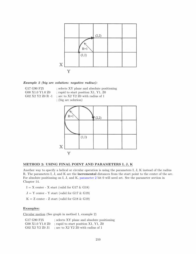
Example 2 (big arc solution: negative radius):
G17 G90 F25 ; selects XY plane and absolute positioningG00 X1.0 Y1.0 Z0 ; rapid to start position X1, Y1, Z0G02 X2 Y2 Z0 R -1 ; arc to X2 Y2 Z0 with radius of 1
; (big arc solution)
METHOD 2: USING FINAL POINT AND PARAMETERS I, J, K
Another way to specify a helical or circular operation is using the parameters I, J, K instead of the radiusR. The parameters I, J, and K are the incremental distances from the start point to the center of the arc.For absolute positioning on I, J, and K, parameter 2 bit 0 will need set. See the parameter section inChapter 14.
I = X center - X start (valid for G17 & G18)
J = Y center - Y start (valid for G17 & G19)
K = Z center - Z start (valid for G18 & G19)
Examples:
Circular motion (See graph in method 1, example 2)
G17 G90 F25 ; selects XY plane and absolute positioningG00 X1.0 Y1.0 Z0 ; rapid to start position X1, Y1, Z0G02 X2 Y2 Z0 J1 ; arc to X2 Y2 Z0 with radius of 1
210

G17 G90 F30 ; select XY plane and absolute positioningG00 X3.0 Y2.0 Z1.0 ; rapid to start position X3, Y2, Z1G02 X2.0 Y1.0 I-1.0 J0.0 Z0.0 ; CW XY arc from X3, Y2 to X2, Y1.
; Center at X2, Y2; Helical Z move from 1 to 0
12.4 G04 - Dwell
G4 causes motion to stop for the specified time. The P parameter is used tospecify the time in seconds to delay. G4 causes the block to decelerate to a full stop.
The minimum delay is 0.01 seconds and the maximum is 327.67 seconds. The dwelltime is performed after all motion is stopped and M functions on the line are com-pleted. If the P parameter is not specified, X will be used instead. If neither P nor Xis specified, the default dwell time of 0.01 seconds will be used.
Example:
G0 X1 Y1 ; rapid to X1, Y1G4 P2.51 ; pause for 2.51 secondsG1 X2 Y2 ; Linear move to X2, Y2
12.5 G09 - Decelerate and Stop (formerly known as Exact Stop)
G9 causes motion to decelerate to a stop and dwell for 1/100 seconds. G9 is equivalentto G4 P0.01. G9 is not modal; it is only effective for the block in which it appears.See G61 (Modal Decelerate and Stop).
Example:
G9 G0 X1 Y1 ; rapid to X1 Y1 and stopX2 Y2 ; continue to X2 Y2
211

12.6 G10 - Parameter Setting
G10 allows you to set parameters for different program operations.
Example:
G10 P73 R.05 ; Sets the peck drilling retract amount to .05G10 P83 R.05 ; Sets the deep drill rapid down clearance to .05G10 P81 R15 ; Sets G81 to use M15 instead of Z movementG10 H5 R-1.3 ; Sets tool length offset #5 to -1.3 in the offset lib.G10 D3 R.25 ; Sets tool diameter offset #3 to .25 in the offset lib.
12.7 G17, G18, G19 - Circular Interpolation Plane Selection
G17, G18, and G19 select the plane for circular interpolation commands (G02 & G03). G17 is the defaultplane. See figure under G2 and G3.
G17 is the XY planeG18 is the ZX planeG19 is the YZ plane
12.8 G20 - Select Inch Units
G20 selects inch units, affecting the interpretation of all subsequent dimensions and feedrates in the jobfile. G20 does not change the native machine units as set on the control setup menu.
12.9 G21 - Select Metric Units
G21 selects metric units, affecting the interpretation of all subsequent dimensions and feedrates in the jobfile. G21 does not change the native machine units, as set on the control setup menu.
12.10 G22/G23 – Work Envelope On/Off
G22 turns on programmable work envelope in machine coordinates. When the machine tries to move intothe forbidden area, let’s say the x-axis, an “x-axis work envelope exceeded” message is displayed, lettingyou know which line of the program is at fault. The work envelope is set with the X, Y, Z for the ‘+’ limitand I, J, K for the ‘–‘limit. G22 is modal and remains on until turned off by G23 or the end of the job.The limits entered in the X, Y, Z and I, J, K parameters are stored in the WCS menu under F3 - WorkEnvel. For more information see chapter 4.
Example:
G22 X-8 I-32 ; Keeps programs from moving into the outside 8 inches ofX- ; axis of travelG1 X-13 F20 ; Would generate a ”X axis work envelope exceeded, line 3” messageG23 ; Allows travel into G22 forbidden area.M25 ; Z homeG0 X-13 ; Ok to move X here now
212

12.11 G28 - Return to Reference Point
G28 moves to the first reference point, by way of an intermediate point. The location of the referencepoint, in machine coordinates, may be set in Work Coordinate System Configuration. The intermediatepoint is specified in the local coordinate system, and may be at the current location (resulting in a movedirectly to the reference point). If an intermediate point is specified, only those axes for which positions arespecified will be moved. If no axes are specified, all axes will be moved.The location of the intermediatepoint is stored for later use with G29. Movement is executed at the maximum (rapid) rate but can bechanged using the L word.
Example:
G28 G91 Z0 ; move Z-axis directly to reference point ( X and Y don’t move)G28 G91 X-.5 Y0 Z0 ; move X -0.5 (from current position), then move all three axes to reference pointG28 G90 X2 Y4 Z.1 ; move all axes to (X2, Y4, Z0.1), then to reference pointG28 ; move all axes to the reference point ( no intermediate point)G28 L100 ; move all axes to the reference point at 100 units/minute
*Note: As with G0 positioning moves, the Z-axis will move separately. If Z is moving up (the usual case)Z will move first, then the other axes. If Z is moving down, the other axes will move first, then Z. Becauseof this, it is rarely necessary to specify an intermediate point different from the current position.
12.12 G29 - Return from Reference Point
G29 moves all axes to the intermediate point stored in a preceding G28 or G30 command. It may be usedto return to the work piece. If a position is specified, the machine will move to that position (in localcoordinates) after reaching the intermediate point. G29 may only be specified after G28 or G30, thoughthere may be intervening moves.
Example:
G29 ; move all axes back from reference point to intermediate pointG29 X1 Y2 ; move all axes to intermediate point, then move to X1 Y2
*Note: As with G0 positioning moves, the Z-axis will move separately. If Z is moving up, Z will movefirst, then the other axes. If Z is moving down (the usual case for G29), the other axes will move first, thenZ will move.
213

12.13 G30 - Return to Secondary Reference Point
G30 functions exactly like G28, except that by default it uses the second reference point from the WorkCoordinate System Configuration table, and the P parameter may be used to request either reference point.
Example:
G30 G91 Z0 ; move Z axis directly to second reference pointG30 P1 ; move all axes to first reference point
*Note: G30 P1 is equivalent to G28.
12.14 G40, G41, G42 - Cutter Compensation
G41 and G42 in conjunction with the selected tool diameter (D code) apply cutter compensation to theprogrammed tool path.
G41 offsets the cutter tool one half of the tool diameter selected with a D code, to the left of the workpiece, relative to the direction of travel.
G42 offsets the cutter tool one half of the tool diameter selected with a D code, to the right of the workpiece, relative to the direction of travel.
G40 cancels G41 and G42.
Example:
G41 D03 ; Tells the machine to compensate left half of the; diameter of the amount that corresponds to D03 in the; Tool Library
Whenever cutter compensation is applied, the following factors must be taken into account in order toobtain proper results.
1. The cutter diameter compensation function (G41, G42) must be implemented before the cutter toolreaches the starting cutting point.
214

Example 1:
G0X0Y0 ; Rapid tool to X0, Y0G42 D3 ; Turn cutter compensation on, with a diameter of D3G0X.5Y2 ; Rapid to X0.5, Y2G1x4.1Y2 ; Linear cut to X4.1, Y2.
; Cut to X4.1 to clear material.G40 ; Turn cutter compensation off.G0X5Y0 ; Rapid to X5, Y0.
You may want to add .1 or .05 inches on the final position for the last cut to clear the material.
*Note: The diameter compensation statement G42 is placed before G0 X.5 Y2. As a result, thecompensation is applied before the cutter reaches the starting cutting point X.5 Y2.
2. If the cutter is down, then the cutter compensation lead-in must always come from an appropriatedirection. Otherwise, the work piece will be incorrectly cut, and the cutter tool could be damaged.One way to avoid this problem is by always keeping the cutter above the work piece whenever atransition is being made to a new starting cutting point. If for some reason this was not possible,then the G-code program should be written so that the cutter compensation lead-in paths do notinterfere with the space occupied by the work piece. Example 2 illustrates a possible harmfuloutcome of programming an inappropriate lead-in direction.
Example 2:
215

G0 X0Y0 ; Rapid tool to X0, Y0G42 D5 ; Turn cutter compensation on, with a diameter of D5G1 X.75Y-1 F5 ; Linear move to X0.75, Y-1. (Notice this damages the
; corner of the work piece)X3.6 ; move X to 3.6G40 ; Turn cutter compensation off.G0 X4Y-2 ; Rapid to X4, Y-2
*Note: This problem could have been avoided by selecting a transitional point between X0 Y0 andX.75 Y-1. A transitional point such as X-1 Y-1 would properly modify the lead-in path, keeping thecutter from damaging the corner of the work piece. Example 3 shows the correct way of performingthis operation.
216

Example 3:
G0X0Y0 ; Rapid tool to X0, Y0G42D5 ; Turn cutter compensation on, with a diameter of D5G0X0Y-1 ; Rapid tool to X0, Y-1G1X.75Y-1 ; Linear cut to X0.75, Y-1.X3.6 ; move X to 3.6G40 ; Turn cutter compensation off.
3. Lookahead. When the control machines any rapid traverse (G0), line (G1), or arc (G2, G3) with tooldiameter compensation enabled, the program will look up to N consecutive events ahead of thecurrent event in order to anticipate tool path clearance problems, where N is the number set inParameter 99. Lookahead ensures that compensated tool paths don’t overlap in programmed partsections where there is not enough clearance for the tool. The figure below shows a compensated toolpath, and the actual tool path after Lookahead corrects the clearance problem:
Refer to the “Machine Parameters” section in Chapter 14 for more information on Parameter 99.
217

12.15 G43, G44, G49 - Tool Length Compensation
G43 and G44 apply tool length compensation to a selected tool to allow the control to utilize multiple toolsin a single CNC program.
G43 applies positive compensation (from Z zero up). Work from part surface up. G44 applies negativecompensation (from Z zero down), used only when there is an absolute machine home. The spindle face isconsidered a zero length tool and all offsets are from there down.
G49 cancels tool length compensation (also canceled by issuing G43 H00).
Example:
G43 H01 ; tells the machine to offset the amount that; corresponds to H01 in the Offset Library
12.16 G43.3 - Tool Length Compensation (+) with Axis TiltCompensation
G43.3 is a special compensation mode which applies positive tool length compensation on a selected tool,just like G43, but also with additional X and Z compensations due to 5th axis tilt. This compensationmode is available only on those machines configured with a triangular rotary 5th axis (see parameter 166 inChapter 14). Note that this compensation mode is the equivalent to G43 as long as the 5th axis is nottilted (i.e. local position is 0). G49 cancels this compensation mode.
12.17 G43.4 - Rotary Tool Center Point (with G43.3Compensation
When G43.4 is active then any feed move (G1) will be made such that the tip of the tool moves in astraight line (this typically causes the Z-axis to move up and down during the move). G43.3 Compensationapplies in this mode.
12.18 G50, G51 - Scaling / Mirroring (Optional)
G50 and G51 scales program G-codes relative to a scaling center point defined as position (X, Y, Z). AG51 applies scaling/mirror to all positions, lines, and arcs following this G-code, until a G50 is entered.Specify scaling factors with a value I, J, K. The X, Y, and Z parameters are the coordinates of the scalingcenter. If the scaling center is not specified, the default scaling center is the current cutter position asshown on the DRO. To mirror, enter a negative value for the scaling factor.
Example, Scaling:
G51 X0.0 Y0.0 Z0.0 I3.0 J2 K1 ; turn scaling onG00 X0.0 Y0.0 Z1.0 ; rapid to X0, Y0, Z1G01 X1.0 Y0.0 Z1.0 ; line to X1, Y0, Z1G01 X1.0 Y1.0 Z1.0 ; line to X1, Y1, Z1G01 X0.0 Y1.0 Z1.0 ; line to X0, Y1, Z1G01 X0.0 Y0.0 Z1.0 ; line to X0, Y0, Z1G01 X0.0 Y0.0 Z0.0 ; line to X0, Y0, Z0G50 ; cancel scale
218

For this G51, the following program lines were scaled 3:1 in the X direction, 2:1 in the Y direction, and 1:1in the Z direction. If no scale factor is specified, the default is 1:1 for all axes.
Example, Mirroring:
G51 X-0.5 Y0.0 Z.0 I-1 J1 K1 ; turn mirror on (x axis -0.5 mirror; line)
G00 X0.0 Y0.0 Z1.0 ; rapid traverse to X0, Y0, Z1G01 X1.0 Y0.5 Z1.0 ; line to X1, Y.5, Z1G01 X0.0 Y1.0 Z1.0 ; line to X0, Y1, Z1G01 X0.0 Y0.0 Z1.0 ; line to X0, Y0, Z1G50 ; cancel mirror
If an arc is scaled with uneven scaling factors, the result will depend on how the arc center and radius werespecified:
1. If the arc radius was specified with R, the radius will be scaled by the larger of the two circular planescale factors. The result will be a circular arc between the scaled arc start and the scaled arc end.
2. If the arc center was specified with I, J, and/or K, the centers will be scaled by the appropriate axisscale factors. The result will be a circular arc from the scaled arc start, around the scaled center, andusually with a line from the end of the circular arc to the scaled arc end.
3. In no case can an ellipse be generated using scaling.
12.19 G52 - Offset Local Coordinate System
G52 shifts the local coordinate system origin by a specified distance. Multiple G52 codes are notcumulative; subsequent shifts replace earlier ones. The G52 shift may therefore be canceled by specifying ashift of zero. If you are using multiple coordinate systems, the G52 shift amount will affect all coordinatesystems.
219

Example:
G0 X0 Y0 ; move to originM98 P9100 ; call subprogramG52 Y4 ; shift coordinate system 4 inches in YG0 X0 Y0 ; move to new originM98 P9100 ; call subprogram again with new coordinatesG52 Y0 ; restore unshifted coordinate system
12.20 G53 - Rapid Positioning in Machine Coordinates
G53 is a one shot code that performs a rapid traverse using machine coordinates. It does not affect thecurrent movement mode (G0-G3) or coordinate system (G54-G59). G53 may only be used with absolutepositioning (G90). Movement rate can be overridden using the L word.
Example:
G53 X15 Y4 Z0 ; move to 15,4,0 in machine coordinatesG53 X15 Y4 Z0 L100 ; move to 15,4,0 in machine coordinates at 100 units/minute
12.21 G54 - G59 - Select Work Coordinate System
G54 through G59 select among the six regular work coordinate systems (WCS #1 through WCS #6).After issuing the code, subsequent absolute positions will be interpreted in the new coordinate system.Alternatively, the codes E1 through E6 to can be used instead of G54 through G59.
Example:
G54 G0 X0 Y0 Z0 ; select first WCS, move to originG2 X1 I.5 Z-.5 ; mill something...G0 Z.1 ; Rapid to position Z0.1G55 X1 Y1 ; select second WCS, move to X1, Y1
Using Extended Work Coordinate Systems (optional): There are 12 additional work coordinate systemsavailable as an extra-cost option. In a G-code program, these 12 additional work piece origins may beselected with either ”G54 P1” (WCS # 7) through ”G54 P12” (WCS #18) or ”E7” through ”E18.”
220

12.22 G61 - Modal Decelerate and Stop (formerly known asExact Stop Mode)
G61 activates Decelerate and Stop mode for every block processed. This forces motionto decelerate to a stop and invokes a brief dwell (1/100 seconds) at the end of eachblock (equivalent to G9 in each block). G61 is modal and remains in effect until it iscanceled with G64. Note that G61 also turns off Smoothing mode.
Example:
G0 X0 Y0 ; move to originG61 X2 ; move and decelerate and stop at X2X4 ; move and decelerate and stop at X4X5 ; move and decelerate and stop at X5
12.23 G64 – Smoothing Mode Selection / Cancel Modal Deceland Stop
G64 has multiple formats with different functionality. Invoking G64 with either an ON or OFF parametersets the Smoothing mode to on or off, and also cancels Modal Decelerate and Stop (G61). Invoking G64without either the ON or OFF parameter simply cancels Modal Decelerate and Stop. Note that all formsof G64 will cancel Modal Decelerate and Stop (Cancel G61).
G64 Format Function
G64Simply cancel Modal Decelerate and Stop (Cancel G61). This does notaffect Smoothing mode.
G64 ON
Turn on Smoothing mode using the current parameter settings (in P221-P228, P230, and P231). The effect of this command is temporary as it isactive only until the next G64 ON/OFF command or until the end of job.Upon the start of the next job, the the inital on/off state of Smoothingwill once again be determined by parameter 220. This command does notmodify any parameters. (This also cancels G61.)
G64 OFF
Turn off Smoothing mode. The effect of this command is temporary as itis active only until the next G64 ON/OFF command or until the end ofjob. Upon the start of the next job, the the inital on/off state of Smoothingwill once again be determined by parameter 220. This command does notmodify any parameters. (This also cancels G61.)
G64 ON ”preset label”G64 ON P (where P isP1-P99)
Turn on and activate Smoothing mode using the specified ”preset label” orpreset number (P1-P99). (See Chapter 14 for further information on settingup Smoothing Presets.) Note that ”preset label” is not case sensitive. Youcan use the preset number to specify those presets that don’t have a ”presetlabel”. These commands have a lasting effect beyond the end of the currentjob because they actually copy the specified Smoothing preset settings intothe current parameters (P221-P228, P230, and P231) and sets P220 to 1.(This also cancels G61.)
G64 ON P0 G64 OFF P0
Turn off and deactivate Smoothing mode. Both forms of this command dothe same thing. The P0 refers to “Exact Stop” mode. This command setsP220 to 0, and thus has a lasting effect beyond the end of the current job.(This also cancels G61.)
Example:
221

G64 ;cancel Modal Decelerate and StopG64 ON ;turn on modal Smoothing modeG64 OFF ;turn off modal Smoothing modeG64 ON P2 ;Activate Smoothing Preset #2 by numberG64 ON ”contouring mill” ;Activate ”Contouring Mill” Preset by labelG64 ON P0 ;Deactivate Smoothing. Activate Exact Stop mode.
12.24 G65 - Call Macro
G65 calls a macro with user-specified values. A macro is a subprogram that executes a certain operation(e.g. drill pattern, contours, etc.) with values assigned to variable parameters within the operation.
Calling methods:
G65 Pxxxx Lrrrr ArgumentsorG65 ”program.cnc” Lrrrr Arguments
where xxxx is the macro number (referring to file Oxxxx.cnc, 0000-9999 allowed, leading zeros required infilename, capital O, lowercase .cnc), rrrr is the repeat value, ”program.cnc” is the name of the macro file,and Arguments is a list of variable identifiers and values.
Arguments to macro calls are specified by using letters A-Z, excluding G, L, N, O, and P.
Macros are written just like normal programs. However, macro programs may access their arguments byusing #A, #B, etc., or by using numbers: #1 for A, #2 for B, etc. (exceptions: #4-6 for I-K, #7-11 forD-H). Arguments I, J, and K can be used more than once in a macro call, with the first set of values storedas #4-6, the second as #7-9, etc., to a maximum of 10 sets. See example at the end of this G65 section.
Macros 9100 - 9999 may be embedded into a main program, using O91xx to designate the beginning of themacro and M99 to end it. The CNC software will read the macro and generate a file O91xx.cnc, but willnot execute the macro. It will be executed when G65 is issued.
Example 1:
Main Program:
G65 ”TEST.cnc” A5 B3 X4
Macro TEST.cnc:
G1 X#X Y#A Z-#B
This call will produce:
G1 X4 Y5 Z-3
Example 2:
Main Program:
G65 ”TEST2.cnc” I5 J3 K40 I-1 J2 I0 J0
Macro TEST2.cnc:
G1 X#4 Y#5 F#6
G1 X#7 Y#8 Z#9
G1 X#10 Y#11 Z#12
222

This call will produce:
G1 X5 Y3 F40
G1 X-1 Y2 Z0
G1 X0 Y0 Z0
Example 3:
Suppose a piece is to have notches of different lengths and depths along the x-axis:
The macro variables would handle the length in the Y direction and depth in the Z direction:
O0002G90 G1 Z0 F30 ; Linear move to Z0Z#Z F5 ; Cut to variable depthG91Y#Y F10 ; Cut variable lengthG90 G0 Z0.1 ; Retract
The main program would call this macro five times, each time specifying the depth and length required.
: Main ProgramG90 G0 X1 Y1 Z0.1 ; Move to first notchG65 P0002 L1 Y1 Z.25 ; Call macro and assign Y=1” and Z=.25”G90 G0 X2.5 Y1 ; Move to second notchG65 P0002 L1 Y1.5 Z.5 ; Call macro and assign Y=1.5” and Z=.5”G90 G0 X4 Y1 ; Move to third notchG65 P0002 L1 Y2 Z.25 ; Call macro againG90 G0 X5.5 Y1 ; Move to fourth notchG65 P0002 L1 Y1.5 Z.5 ; Call macro againG90 G0 X7 Y1 ; Move to fifth notchG65 P0002 L1 Y1 Z.25 ; Call macro again: End program
223

12.25 G68, G69 - Coordinate Rotation on/off
G68 rotates program G-codes a specified angle R. G68 rotates all positions, lines, and arcs until a G69 isentered. The center of rotation can be specified by X, Y and Z values (X, Y for G17 plane). If the center isnot specified then a default center of rotation is used as determined by machine parameter 2 (see Chapter14 for parameter 2). The default plane of rotation is G17 (X, Y).
Example:
G68 R45 X4 Y2 ; Rotate 45 degrees centered on X4 Y2G0 X3.0 Y1.0 ; Rapid to positionG1 X5.0 Y1.0 F20 ; Start part profileX5.0 Y3.0X4.125 Y3.0G3 X4.0 Y2.875 J-0.125G1 X4.0 Y2.125G2 X3.875 Y2.0 I-0.125G1 X3.125 Y2.0G3 X3.0 Y1.875 J-0.125G1 X3.0 Y1.0 ; End part profileG69 ; Rotate Off
12.26 G68.1 — Transformed Work Coordinate System
G68.1 turns on Transformed Work Coordinate System during a job. G69 turns it off. For moreinformation, see the Transformed Work Coordinate System section of the Part Setup Menu chapter.
224

12.27 G73, G76, G80, G81, G82, G83, G85, G89 - CannedDrilling/Boring Cycles; G74, G84 - Canned TappingCycles
G code-Z direction (ma-chine hole)
Operation at bot-tom of hole
+Z direction Use
G73Intermittent Feed(Set with the Qparameter)
——— Rapid traverseHigh speed peckdrilling cycle
G74 FeedSpindle CW, thenDwell (Set with the Pparameter)
FeedCounter tapping(Left-hand thread)
G76 Feed
Dwell (P parameter),Orient Spindle (viaM19), Move Y+ (Qparameter)
Rapid traverse, thenStop Spindle Orient(via M5)
Fine Boring Cycle
G80 ——— ——— ———Cancels canned cy-cles
G81 Feed ——— Rapid traverseRegular and spotdrilling cycles andair drill cycle
G82 FeedDwell (Set with the Pparameter)
Rapid traverseRegular and counterboring cycles, spotfacing
G83Intermittent Feed(Set with the Qparameter)
——— Rapid traversePeck and deep holedrilling cycles
G84 FeedSpindle CCW, thenDwell (Set with the Pparameter)
FeedTapping (Right handthread)
G85 Feed ——— Feed Boring cycle
G89 FeedDwell (Set with the Pparameter)
Feed Boring cycle
Table 1. Canned drilling, boring and tapping cycles
Canned Cycle Operation
225

Operation 1: Position the X, Y axes.Operation 2: Rapid traverse to the position labeled R.Operation 3: Machine hole.Operation 4: Bottom hole operation.Operation 5: Return to point R.Operation 6: Rapid traverse to initial point.
Canned cycle G-code syntax
(Cycle codes do not have to be on the same line) G Canned cycle G-code from table 1.
X X position of the hole to be drilled.
Y Y position of the hole to be drilled.
Z Specifies point Z in figure 1. In incremental mode Z is measured from point R. In absolute mode Z isthe position of the hole bottom.
R Specifies the distance to point R (figure 1) with an absolute or incremental value.
Q Determines the cut-in depth for the G73 and G83 cycles. Determines the thread lead for G74 andG84 if Rigid Tapping is enabled. (In the case of Rigid Tapping Q is not modal)
P Sets the dwell time at the bottom of the holes for G74, G82, G84, and G89 cycles. The dwell time ismeasured in seconds (same as G04).
F Sets the feed rate. Remains the feedrate even after G80 (cancel canned cycles).
K Sets the number of repeats for drilling cycles. Operations 1 through 6 of figure 1 will be repeated Knumber of times. If K is not specified K = 1. K is only useful when using incremental positioning mode(G91) and is not retained from cycle to cycle. In absolute mode, K causes the drilling of the same hole inthe same position K times.
*Note: Canned cycles are modal and should be canceled with G80. However G00, G01, G02 and G03 willalso cause the cancellation of canned cycles. All parameters are stored until canned cycles are canceledexcept for the hole position and K, which must be set each time the cycle is used. When G80 is issued themovement mode will be the last one issued (G0, G1, G2, G3). Canned cycles will not be performed unlessX and/or Y are specified.
226

When performing canned cycle operations, the distances can be either incremental or absolute, dependingon the current active mode (G90 = absolute, G91= incremental). Figure 2 illustrates canned cycle Z-axisdistances in both modes.
*Note: In incremental mode the Z depth of the hole is measured from R, and R is measured from theinitial tool position.
Example:
(Part surface height is Z = 0, initial tool position is X.50 Y1.0 Z.625. Drill 0.50 deep hole at X1.0 Y1.0;clearance height (R) is 0.10 above surface.)
Absolute IncrementalG90 G91G81 X1 Y1 R.1 Z-.5 G81 X.5 Y0 R-.525 Z-.6G80 G80
*Note: for Articulated Head machines configured with the TWCS feature enabled via Parameter 166: Ifthe currently selected WCS is non-TWCS (TWCS = No) and the B axis is at an angle other than 0, thenyou cannot use the regular Canned Cycle G-codes G73, G74, G76, G81, G82, G83, G84, G85, G89. Youmust use the Compound Canned Cycle G-codes G173, G174, G176, G181, G182, G183, G184, G185, G189instead. Using regular Canned Cycle G-codes when the B axis is not 0 is an error and will cancel the job.See ”G173, G174... – Compound Canned Cycles” later in this chapter for more information about thissubject. See Chapter 14 for more information about Parameter 166.
227

12.28 G73 - High Speed Peck Drilling
G73 is the peck drilling cycle. The hole is drilled in a series of moves: down a distance Q at a givenfeedrate, up the retract distance at the rapid rate, and then down again at the given feedrate. The retractamount is set with G10 as shown in the example below.
Example:
G90 ; Absolute positioningG01 X3.00 Y1.50 Z.5 ; G01 mode before canned cycleG98 ; Set for initial point returnG10 P73 R.1 ; Sets the retract amount to .1G73 X3.250 Y1.75 Z-.650 R.1 Q0.325 F3 ; Peck drill at X3.25 Y1.75X4.5 Y3.5 ; Peck drill at X4.5 Y3.5G80 ; Cancel canned cycle, return
228

12.29 G74 - Counter Tapping
G74 performs left-hand tapping. The spindle speed (and feedrate, if you are doing floating tapping) shouldbe set and the spindle started in the CCW direction before issuing G74. G74 will normally use the defaultM3 to select spindle CW (at the bottom of the hole) and M4 to re-select spindle CCW (after backing outof the hole) depending on the settings of parameters 74 and 84.
The tap may continue to cut a short distance beyond the programmed Z height as the spindle comes to astop before reversing. When tapping blind holes, be sure to specify a Z height slightly above the bottom ofthe hole to prevent the tool from reaching bottom before the spindle stops.
Note: If rigid tapping is enabled, a Q may be used to set the thread lead or pitch. However, because Q isnot modal in the case of Rigid Tapping, you must specify Q on every line at which Rigid Tapping is tooccur.
Note: At the bottom of the hole, G74 will call the default version of the specified M function even if it hasbeen customized by an M function macro.
FEED HOLD is temporarily disabled during the tapping cycle, but it willbe re-enabled at the end of the cycle.
Pressing CYCLE CANCEL while the tap is in the hole will very probablybreak the tap or strip the threads in the tap hole. However, do so if it isan emergency.
Example:
M4 S500 F27.78 ; start spindle CCW, set up for 18 pitch tapG74 X1 Y1 R.1 Z-.5 ; counter-tap a 0.5 deep hole at X1 Y1Y1.5 ; ... and another one at X1 Y1.5G80 ; cancel canned cycles
229

12.30 G76 –– Fine Bore Cycle
G76 requires that the machine be capable of orienting the spindleand that a custom M19 macro is present in order to commandthe inverter to orient the spindle. Please contact your dealerto confirm that your machine meets these requirements beforeattempting to use this cycle.
NOTE: Parameter 136 = Fine Bore retract angle (0-360 degrees). A setting of 0 = Retract in Y+direction Format G76 X Y Z R Q R = Point R Q = Distance to pull away from wall in Y+direction at bottom of hole.
Example:
G76 X1 Y1 Z-3 R.1 Q.2 ; Bore hole at X1 Y1 retract .2 in Y+ directionY10 ; ... and another one at X1 Y10G80 ; cancel canned cycles
12.31 G81 - Drilling and Spot Drilling
G81 is a general purpose drilling cycle. The hole is drilled in a single feedrate move, and then the tool isretracted at the rapid rate.
230
Example:
G90 ; Absolute positioningG01 X3.00 Y1.50 Z.5 ; G01 mode before canned cycleG99 ; Set for R point returnG81 X3.250 Y1.75 Z-.650 R.1 F3 ; Drill at X3.25 Y1.75X4.5 Y3.5 ; Drill at X4.5 Y3.5G80 ; Cancel canned cycle, return to G1
12.32 G81 - Drill Cycle Transformation to G81 Air Drill Cycle
G81 may be modified to execute an M function instead of moving the Z-axis by setting parameter 81 to thedesired M function. Example use is for air-actuated drills.
Example: Execute M39 each time a new G81 position is given:
G10 P81 R39 ; Set parameter 81 to 39 (G81 air drill with M39)G81 X5 ; Move to X5 and execute M39Y3 ; Move to Y3 and execute M39
To revert to Z-axis drilling, specify M function #-1.
Example:
G10 P81 R-1 ; Set parameter 81 to -1 (G81 drilling cycle)
M function #39 is designed for general air drill use. See the description of M39 in the M functions section.
A different M function may be used instead, but any M function used must be a macro file that uses theM103 and M104 commands to time the cycle (see the example in the M function section under M103). Ifthe macro file does not use M103, the control will automatically cancel the job 1/2 second after startingG81. For information on creating customized M functions, review Macro M functions in Chapter 13.
The M39 default air drill cycle has a time out of 2.0 seconds. As a result, if the cycle does not completewithin 2 seconds then the cycle aborts and the output relay is turned off under PLC program control.
*Note: The PLC program must be involved in the execution of the cycle. The PLC program isresponsible for turning on relays based on M function requests and the status of program execution. ThePLC program must also stop all programmed machine functions when the program is canceled. See theM39 description (Chapter 13) for a sample of an air drill cycle M function.
231

12.33 G82 - Drill With Dwell
G82 is a general purpose drilling cycle similar to G81. However, G82 includes an optional dwell at thebottom of the hole before retracting the tool. This can make the depth of blind holes more accurate.
Example:
G82 X1 Y1 R.1 Z-.5 P.5 ; drill to Z-.5, dwell .5 seconds
232

12.34 G83 - Deep Hole Drilling
G83 is a deep hole drilling cycle. It periodically retracts the tool to the surface to clear accumulated chips,then returns to resume drilling where it left off. The retract and return are performed at the rapid rate.
233

Because there may be chips in the bottom of the hole, the tool does not return all the way to the bottomat the rapid rate. Instead it slows to feedrate a short distance above the bottom. This clearance distance isselected by setting Parameter 83 with G10 (see example below).
2 Line Format
Line 1: G10 P83 R_*
Line 2: G83 X_ Z_ Q_ R_ L_
Line 1 — R = Z Rapid to Clearance Amount *
Line 2 — X = X Position
Line 2 — Z = Final Z depth
Line 2 — Q = Z Peck Cutting Increment †
Line 2 — R = R(Z) Return point for clearance
Line 2 — L = Dwell time at each Final Z depth
* The modal default for Z Rapid to Clearance Amount is from Parameter 83. If Line 1 is not present, thedefault value in parameter 83 will be used.
† Q value is subject to the ”implied floating point” re-interpretation rules of Parameters 245 and 246,
Final Z depth, the Z Peck Cutting Increment (Q), and Return Point (R) are the minimal requiredparameters. All others are optional. If X is not specified, the last X position will be used. X should alwaysX0.0 unless the machine is set up with C-axis and live tooling.
Dwell Time (L) should be left out entirely if no dwell is desired because L0 will still cause a (albeit verybrief) dwell.
Example:
G10 P83 R.05 ; set clearance to .05”G83 X0 Y0 R.1 Z-2 Q.5 ; drill 2” deep hole in 0.5” stepsG80 ; cancel canned cycle
234

12.35 G84 - Tapping
G84 performs right-hand tapping. The spindle speed (and feedrate, if you are doing floating tapping)should be set and the spindle started in the CW direction before issuing G84. G84 will normally use thedefault M4 to select spindle CCW (at the bottom of the hole) and M3 to re-select spindle CW (afterbacking out of the hole) depending on the settings of parameters 74 and 84.
The tap may continue to cut a short distance beyond the programmed Z height as the spindle comes to astop before reversing. When tapping blind holes, be sure to specify a Z height slightly above the bottom ofthe hole to prevent the tool from reaching bottom before the spindle stops.
For a floating tap head, the combination of the modal feedrate and spindle speed implicitly determines theapproximate thread lead or pitch. Note: If rigid tapping is enabled, a Q may be used to set the thread leador pitch. However, because Q is not modal in the case of Rigid Tapping, you must specify Q on every lineat which Rigid Tapping is to occur.
Note: At the bottom of the hole, G84 will call the default version of the specified M function even if it hasbeen customized by an M function macro.
The Tap/Counter Tap cycle might cut a short distance beyond the programmed Z height as the spindlecomes to a stop before reversing. When tapping blind holes, be sure to specify a Z height slightly above thebottom of the hole to prevent the tool from reaching bottom before the spindle stops. The exact distanceyou must allow will depend on your machine and the diameter and pitch of the tapping tool.
FEED HOLD is temporarily disabled during the tapping cycle, but it willbe reenabled at the end of the cycle.
Pressing CYCLE CANCEL while the tap is in the hole will very probablybreak the tap or strip the threads in the tap hole. However, do so if it isan emergency.
Example:
235
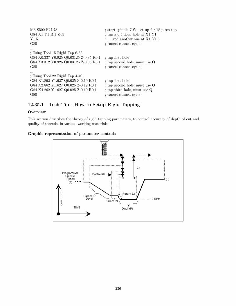
M3 S500 F27.78 ; start spindle CW, set up for 18 pitch tapG84 X1 Y1 R.1 Z-.5 ; tap a 0.5 deep hole at X1 Y1Y1.5 ; ... and another one at X1 Y1.5G80 ; cancel canned cycle...; Using Tool 15 Rigid Tap 6-32G84 X0.337 Y0.925 Q0.03125 Z-0.35 R0.1 ; tap first holeG84 X3.312 Y0.925 Q0.03125 Z-0.35 R0.1 ; tap second hole, must use QG80 ; cancel canned cycle...; Using Tool 22 Rigid Tap 4-40G84 X1.862 Y1.627 Q0.025 Z-0.19 R0.1 ; tap first holeG84 X2.862 Y1.627 Q0.025 Z-0.19 R0.1 ; tap second hole, must use QG84 X4.262 Y1.627 Q0.025 Z-0.19 R0.1 ; tap third hole, must use QG80 ; cancel canned cycle
12.35.1 Tech Tip - How to Setup Rigid Tapping
Overview
This section describes the theory of rigid tapping parameters, to control accuracy of depth of cut andquality of threads, in various working materials.
Graphic representation of parameter controls
236

List of Rigid tapping setup parameters – see Chapter 14 for more details
Parameter Function34 Spindle Encoder Counts/Rev35 Spindle Encoder Axis Number36 Rigid Tapping Enable/Disable37 Spindle Deceleration Time68 Minimum Rigid Tapping Spindle Speed69 Duration For Minimum Spindle Speed74 M-Function executed at bottom of tapping cycle84 M-Function executed at return to initial point of tapping cycle82 Spindle Drift Adjustment
12.35.2 Graphic representation of test results for precision
The above charts show test results of rigid tapping, utilizing version 7.14 software. The tool used in thetesting was a 1/2-13 spiral fluted tap with TiN coating. Coolant used was water base soluble oil. Hole sizewas .4218. Tapping depth was .800. Also note that the parameters were adjusted to cut air, and notchanged for aluminum or cold rolled steel for these tests. It can be seen, as the material changes, so doesthe off target values. This is due in part to the amount of torque required from the spindle to cut thevarious types of material. For testing purposes, the parameter settings for the above results were as follows:
Parameter 36 = 1, Parameter 37 = 3, Parameter 68 = 100, Parameter 69 = 1.25, Parameter 82 = 108
Summary
Rigid tapping parameters will vary from machine to machine. Not all machines are built the same (i.e.Spindle hp, inverter type, rigidity, etc.), and tooling will play a roll in performance also. It was foundthrough our testing, if we changed one physical parameter, (i.e. using a tapping oil instead of water basecoolant), it improved the off target values by 1.5%. This is due to the fact that less friction is present whenusing special cutting oil, therefore requiring less hp by the spindle to drive the tap. In most cases, rigidtapping depths should be able to be held within +/- .008 inch or less by adjusting parameter 82 for specificcases.
237

12.36 G85 – Boring
G85 is similar to G81, except that the tool is retracted with a feedrate move instead of a rapid move. G85may be used for tapping with reversing tap heads such as the Tapmatic NCR series.
Example 1:
G85 X1 Y1 R.1 Z-.5 ; bore a 0.5” hole at X1 Y1G80 ; cancel canned cycle
Example 2:
M3 S500 F27.78 ; start spindle CW, set for 18 pitch tapM109/1/2 ; disable feedrate and spindle overridesG85 X1 Y1 R.1 Z-.4 ; tap hole at X1 Y1 to a depth of 0.4”M108/1/2 ; enable feedrate and spindle overridesG80 ; cancel canned cycle
238

12.37 G89 - Boring cycle with dwell
G89 is similar to G85, except that it includes an optional dwell at the bottom of the hole before retractingthe tool.
Example:
G89 X1 Y1 R.1 Z-.5 P.1 ; bore 0.5” hole at X1 Y1, dwell .1 secondsG80 ; cancel canned cycle
12.38 G90 & G91 - Absolute/Incremental Positioning Mode
G90 selects absolute positioning, and G91 selects incremental positioning. In absolute positioning, allcoordinates are relative to the origin (0,0,0,0). In incremental positioning, all coordinates are distancesrelative to the last point.
G90 Absolute positioningG91 Incremental coordinates
Example:
G90 X2 Y3 ; moves the X and Y axes from the current position; to X2, Y3.
G91 X1 Y0 ; moves the X axis 1 inch referenced from the last X; position, the Y axis does not move.
239

12.39 G92 - Set Absolute Position
G92 sets the current absolute position to the coordinates specified. This command only affects thecurrently set Work Coordinate System.
Example:
G0 X5 Y3 Z-2 W5 ; Moves to the specified locationG92 X1 Y0 Z0 W1 ; Sets the current position to the absolute
; position specified.
12.40 G93 - Inverse Time
Rather than using a conventional federate in Inch per Minute or MM per Minute, F in inverse time modespecifies the movement frequency for subsequent moves. Specifically, the inverse time feedrate is the inverseof the amount of time that a move is allowed to take.
For example, using inverse time, the block:G1 G93 X10 F1
takes 1 minute to cut, regardless of X length. At F2.0 (1/2.0 minute) it takes 30 seconds; At F3.0 it takes20 seconds, and so on.
G93 is Modal, and remains in effect until a G94 is issued to cancel the G93.
Example of use in a program:
G0 G54 G90 X2.2126 Y-1.1995 A94.75 B-.161 S3000 M3 ; Move to startG43 H26 Z7.0002 M8Z3.1002G1 G93 X2.2048 Y-1.2593 Z3.0204 F100. ; Enable Inverse TimeX2.2052 Y-1.2586 Z3.0202 A94.756 B-.162 F30000. ; 1/30000 min for moveX2.2079 Y-1.2578 Z3.0197 A94.763 B-.173 F30000. ; 1/30000 min for moveX2.2124 Y-1.2566 Z3.0189 A94.773 B-.189 F30000. ; 1/30000 min for moveX2.2184 Y-1.2551 Z3.0179 A94.786 B-.212 F24065.56 ; 1/24065 min for moveX2.2258 Y-1.2533 Z3.0167 A94.802 B-.24 F19736.14 ; 1/19736 min for moveX2.2345 Y-1.2512 Z3.0155 A94.819 B-.272 F17187.45 ; 1/17187 min for move
12.41 G93.1 – Velocity Scrubber for Smoothed Inverse TimeData
This special feedrate interpretation mode substitutes inverse time feedrates (usually posted from aCAD/CAM program) with optimized feedrates to ensure that the tool tip center is moved at a set feedratein physical 3D space, taking into account tool length offset and the machine geometry as set by parameters116-119 (see Chapter 14) . The set feedrate (F) can be on the same G-code line as the G93.1 or can be thelast modal feedrate specified on prior G-code lines.
This mode is intended for CNC jobs run on machines configured with a triangular rotary 5th axis such as aTilt Table or Articulated Head (see parameter 166 in Chapter 14), although that is not an enforced definiterequirement to turn on this mode. It is recommended that moves programmed with this mode should be insmall vectors, and any long moves that require a sweep of a rotary axis by more than 10 degrees should bebroken up into 2 or more smaller moves. Note that Smoothing must also be turned on (P220 = 1) for thisfeature to work; otherwise, it will be treated as a regular G93 (Inverse Time).
240

Example of use in a program (based on the example from G93 above):
G0 G54 G90 X2.2126 Y-1.1995 A94.75 B-.161 S3000 M3 ; Move to startG43 H26 Z7.0002 M8Z3.1002G1 G93.1 X2.2048 Y-1.2593 Z3.0204 F150. ; Force tool tip to move 150 in/minX2.2052 Y-1.2586 Z3.0202 A94.756 B-.162 F30000. ; Ignore F..Move at 150ipmX2.2079 Y-1.2578 Z3.0197 A94.763 B-.173 F30000. ; Ignore F..Move at 150ipmX2.2124 Y-1.2566 Z3.0189 A94.773 B-.189 F30000. ; Ignore F..Move at 150ipmX2.2184 Y-1.2551 Z3.0179 A94.786 B-.212 F24065.56 ; Ignore F..Move at 150ipmX2.2258 Y-1.2533 Z3.0167 A94.802 B-.24 F19736.14 ; Ignore F..Move at 150ipmX2.2345 Y-1.2512 Z3.0155 A94.819 B-.272 F17187.45 ; Ignore F..Move at 150ipm
12.42 G94 - Cancel Inverse Time
G94 is used to cancel Inverse Time feedrates, and return to regular Feed per Minute feedrates.
12.43 G98 - Initial Point Return
G98 sets the +Z return level to point I as pictured in Figure 1 in the Canned Cycle Section. (G98 is thedefault setting)
12.44 G99 - R Point Return
G99 sets the +Z return level to point R as pictured in Figure 1 in the Canned Cycle Section.
12.45 G117, G118, G119 - Rotation of Pre-set Arc Planes
G117, G118 and G119 have the same functionality as G17, G18 and G19, respectively, except that theyinclude 2 optional parameters P and Q to specify the arc plane rotation away from the pre-set arc plane: Pspecifies the arc plane angle of rotation (in degrees) around the first axis and Q specifies the arc planeangle of rotation around the second axis.
For the G117 plane, the ”first axis” is X and the ”second axis” is Y.
For the G118 plane, the ”first axis” is Z and the ”second axis” is X.
For the G119 plane, the ”first axis” is Y and the ”second axis” is Z. If P and/or Q are not specified, theangles are assumed to be 0 degrees. If both P and Q parameters are 0, then the plane is assumed to be anorthogonal (pre-set) arc plane. The center of the arc can be specified by the user in a 3D form both in
241

G17-G19 and in G117-G119 (all I, J, K values are allowed at the same time with G2 and G3). Any arccenter component outside the circular plane is ignored.
Example:
G00 X0 Y0 Z1 ; rapid moveG03 G18 X1 Y0 Z0 K-1 F20 ; arc millG00 X0 Y0 Z1.1 ; retract moveG01 Z1 ; move to start of contourG03 G118 P1.000000 X0.9998 Y0.0175 Z0 K-1 ; arc mill rotated about Z
*Note: G117-G119 will not be permitted while cutter compensation is turned on. Also, scaling is notallowed while G117-G119 is specified and G117-G119 is not allowed while scaling is active.
*Note: G117-G119 will not work when Smoothing is turned on (P220 = 1).
12.46 G173, G174, G176, G181, G182, G183, G184, G185, G189– Compound Canned Cycles
On a machine configured as an Articulated Head machine with the TWCS feature enabled, the CompoundCanned Cycle G-codes are used to perform tilted-head Drill/Bore/Tap operations when the currentlyselected WCS is not transformed (TWCS=No). See Parameter 166 in Chapter 14 for information onArticulated Head configuration and turning on the TWCS feature for the machine.
On a such a machine, Compound Canned Cycles are used as an alternative to the their correspondingnoncompound Canned Cycles because the non-compound versions cannot be used when the currentlyselected WCS is not transformed (TWCS=No) and the spindle head is tilted off vertical (B/5th axis angleis not 0). In all other situations, Compound Canned Cycles are the same in functionality as theircorresponding non-compound counterparts.
Compound Canned Cycle G-code
FunctionCorresponding non-compoundCanned Cycle G-code
G173Compound High Speed PeckDrilling
G73
G174 Compound Counter Tapping G74G176 Compound Fine Bore Cycle G76
G181Compound Drilling and SpotDrilling
G81
G182 Compound Drill with Dwell G82G183 Compound Deep Hole Drilling G83G184 Compound Tapping G84G185 Compound Boring G85G189 Compound Boring with Dwell G89
12.47 G180 – Cancel Canned Cycles
G180 has the exact same functionality as G80.
242

Chapter 13
CNC Program Codes: M-Functions
M functions are used to perform specialized actions in CNC programs. Most of the M-series Control Mfunctions have default actions, but can be customized with the use of macro files.
13.1 Summary of M Functions
13.1 Summary of M Functions . . . . . . . . . . . . . . . . . . . . . . . . . . . . . . . . . . . 243
13.2 Macro M functions (Custom M Functions) . . . . . . . . . . . . . . . . . . . . . . . . . 244
13.3 M00 - Stop for Operator . . . . . . . . . . . . . . . . . . . . . . . . . . . . . . . . . . . 245
13.4 M01 - Optional Stop for Operator . . . . . . . . . . . . . . . . . . . . . . . . . . . . . . 245
13.5 M02 - Restart Program . . . . . . . . . . . . . . . . . . . . . . . . . . . . . . . . . . . . 245
13.6 M03 - Spindle On Clockwise . . . . . . . . . . . . . . . . . . . . . . . . . . . . . . . . . 246
13.7 M04 - Spindle On Counterclockwise . . . . . . . . . . . . . . . . . . . . . . . . . . . . . 246
13.8 M05 - Spindle Stop . . . . . . . . . . . . . . . . . . . . . . . . . . . . . . . . . . . . . . 246
13.9 M06 - Tool Change . . . . . . . . . . . . . . . . . . . . . . . . . . . . . . . . . . . . . . 246
13.10 M07 - Mist Coolant On . . . . . . . . . . . . . . . . . . . . . . . . . . . . . . . . . . . . 247
13.11 M08 - Flood Coolant On . . . . . . . . . . . . . . . . . . . . . . . . . . . . . . . . . . . 247
13.12 M09 - Coolant Off . . . . . . . . . . . . . . . . . . . . . . . . . . . . . . . . . . . . . . . 247
13.13 M10 - Clamp On . . . . . . . . . . . . . . . . . . . . . . . . . . . . . . . . . . . . . . . . 247
13.14 M11 - Clamp Off . . . . . . . . . . . . . . . . . . . . . . . . . . . . . . . . . . . . . . . . 247
13.15 M17 - Prepare for Tool Change (Macro) . . . . . . . . . . . . . . . . . . . . . . . . . . . 247
13.16 M19 - Spindle Orient (Macro) . . . . . . . . . . . . . . . . . . . . . . . . . . . . . . . . 248
13.17 M25 - Move to Z Home . . . . . . . . . . . . . . . . . . . . . . . . . . . . . . . . . . . . 248
13.18 M26 - Set Axis Home . . . . . . . . . . . . . . . . . . . . . . . . . . . . . . . . . . . . . 248
13.19 M30 - Custom M Code . . . . . . . . . . . . . . . . . . . . . . . . . . . . . . . . . . . . 248
13.20 M39 - Air Drill . . . . . . . . . . . . . . . . . . . . . . . . . . . . . . . . . . . . . . . . . 248
13.21 M41, M42, M43 - Select Spindle Gear Range (Macros) . . . . . . . . . . . . . . . . . . . 249
13.22 M60 - 5-Axis Digitizing Macro . . . . . . . . . . . . . . . . . . . . . . . . . . . . . . . . 249
13.23 M91 - Move to Minus Home . . . . . . . . . . . . . . . . . . . . . . . . . . . . . . . . . 250
13.24 M92 - Move to Plus Home . . . . . . . . . . . . . . . . . . . . . . . . . . . . . . . . . . 250
13.25 M93 - Release/Restore Motor Power . . . . . . . . . . . . . . . . . . . . . . . . . . . . . 250
13.26 M94/M95 - Output On/Off . . . . . . . . . . . . . . . . . . . . . . . . . . . . . . . . . . 251
13.27 M98 - Call Subprogram . . . . . . . . . . . . . . . . . . . . . . . . . . . . . . . . . . . . 251
13.28 M99 - Return from Macro or Subprogram . . . . . . . . . . . . . . . . . . . . . . . . . . 253
13.29 M100 - Wait for PLC bit (Open, Off, Reset) . . . . . . . . . . . . . . . . . . . . . . . . 253
13.30 M101 - Wait for PLC bit (Closed, On, Set) . . . . . . . . . . . . . . . . . . . . . . . . . 253
243

13.31 M102 - Restart Program . . . . . . . . . . . . . . . . . . . . . . . . . . . . . . . . . . . 254
13.32 M103 - Programmed Action Timer . . . . . . . . . . . . . . . . . . . . . . . . . . . . . . 254
13.33 M104 - Cancel Programmed Action Timer . . . . . . . . . . . . . . . . . . . . . . . . . 254
13.34 M105 - Move Minus to Switch . . . . . . . . . . . . . . . . . . . . . . . . . . . . . . . . 254
13.35 M106 - Move Plus to Switch . . . . . . . . . . . . . . . . . . . . . . . . . . . . . . . . . 254
13.36 M107 - Output Tool Number . . . . . . . . . . . . . . . . . . . . . . . . . . . . . . . . . 255
13.37 M108 - Enable Override Controls . . . . . . . . . . . . . . . . . . . . . . . . . . . . . . 255
13.38 M109 - Disable Override Controls . . . . . . . . . . . . . . . . . . . . . . . . . . . . . . 255
13.39 M115/M116/M125/M126 - Protected Move Probing Functions . . . . . . . . . . . . . . 255
13.40 M115/M116/M125/M126 - DSP Probe specific information . . . . . . . . . . . . . . . . 256
13.41 M120 - Open data file (overwrite existing file) . . . . . . . . . . . . . . . . . . . . . . . 257
13.42 M121 - Open data file (append to existing file) . . . . . . . . . . . . . . . . . . . . . . . 258
13.43 M122 - Record local position(s) and optional comment in data file . . . . . . . . . . . . 258
13.44 M123 - Record value and/or comment in data file . . . . . . . . . . . . . . . . . . . . . 258
13.45 M124 - Record machine position(s) and optional comment in data file . . . . . . . . . . 259
13.46 M127 - Record Date and Time in a data file . . . . . . . . . . . . . . . . . . . . . . . . 259
13.47 M128 - Move Axis by Encoder Counts . . . . . . . . . . . . . . . . . . . . . . . . . . . . 259
13.48 M129 - Record Current Job file path to data file . . . . . . . . . . . . . . . . . . . . . . 259
13.49 M130 - Run system command . . . . . . . . . . . . . . . . . . . . . . . . . . . . . . . . 259
13.50 M150 - Set Spindle Encoder to zero at next index pulse . . . . . . . . . . . . . . . . . . 260
13.51 M200, M223, M224, M225 & M290 - Formatted String Commands . . . . . . . . . . . . 260
13.52 M200/M201 - Stop for Operator, Prompt for Action . . . . . . . . . . . . . . . . . . . . 261
13.53 M223 - Write Formatted String to File . . . . . . . . . . . . . . . . . . . . . . . . . . . 261
13.54 M224 - Prompt for Operator Input Using Formatted String . . . . . . . . . . . . . . . . 262
13.55 M225 - Display Formatted String for A Period of Time . . . . . . . . . . . . . . . . . . 262
13.56 M290 - Digitize Profile (Optional) . . . . . . . . . . . . . . . . . . . . . . . . . . . . . . 262
13.57 M300 - Fast Synchronous I/O update . . . . . . . . . . . . . . . . . . . . . . . . . . . . 263
13.58 M333 - Axis Role Re-assignment . . . . . . . . . . . . . . . . . . . . . . . . . . . . . . . 263
13.59 M1000-M1015 - Graphing Color for Feedrate movement . . . . . . . . . . . . . . . . . . 263
* M functions marked with ”(macro)” actually have no standard default action, and could possibly beunimplemented and therefore unavailable on your machine. Also, their stated function is only standard oncertain machines.
13.2 Macro M functions (Custom M Functions)
Most M -Series CNC M functions from 0 through 90 can be fully customized. Exceptions are M2, M6, andM25 that can be customized, but will always move the 3rd (Z) axis to the home position before executingthe macro M function commands. No M functions above 90 may be customized with macros. The defaultaction listed will be performed unless that M function has been customized.
To create a macro for an M-function, a file must be created in the C:\cncm directory. The file’s name mustbe mfuncXX.mac where XX is the M function number used to call the macro. M functions 0-9 must usesingle digits in the filename (e.g. Use mfunc3.mac, not mfunc03.mac). The contents of the file may be anyvalid M and G codes.
Each time the M function is encountered in a program, the macro file will be processed line by line.
NOTE: Nesting of macro M functions is allowed. Recursive calls are not: if a macro M function callsitself, the default action of the function will be executed.
Example:
244
Turn on spindle with variable frequency drive and wait for ”at speed” response. This example depends onM94/M95 1 being used for the Spindle Enable signal and input 5 being the spindle at speed signal in thePLC program.
Create file c:\cncm\mfunc3.mac with contents as follows:
M94/1 ; request spindle startM101/50005 ; wait for up to speed signal
M2, M6, and M25 always move the Z-axis to the home position before any other motion. All other Mfunctions are performed after the motion of the current line is complete.
The M and G codes in a macro M function are not usually displayed on the screen as they are executed,and are all treated as one operation in block mode. If you wish to see or step through macro M functions(e.g. for testing purposes), set parameter 10 as follows:
0 Don’t display or step through macro M functions1 Display macro M functions, but don’t step through them2 Display and step through macro M functions
NOTES:
• You cannot use block mode to step through a macro M function called using the G81 transformation(see Chapter 12); the action timer will expire before you can press CYCLE START.
• Only one M function per line is permitted.
• Unlike subprograms invoked with G65, macro arguments passed into a macro M function are passedin by reference. This means local changes to #1 through #33 or #A through #Z will change thetheir values upon return from the macro M function.
13.3 M00 - Stop for Operator
Motion stops, and the operator is prompted to press the CYCLE START button to continue.
13.4 M01 - Optional Stop for Operator
M1 is an optional pause, whose action can be selected by the operator.
When optional stops are turned on, M1 will pause the currently running job until CYCLE START ispressed.However, if optional stops are turned off, M1 will not pause the program.
NOTE: If you plan to override the default action of M1 with a macro file, you may want to include a callto M1 within the macro file so that the default actions of M1 will still be effective in the overridden M1.Otherwise, if a call to M1 is not included within the macro file, the new overridden M1 will cause optionalstops to be ineffective.
13.5 M02 - Restart Program
M2 moves the Z-axis to the home position, performs any movement requested, and restarts the programfrom the first line. The operator is prompted to press the CYCLE START button to continue.
245
13.6 M03 - Spindle On Clockwise
M3 requests the PLC to start the spindle in the clockwise direction.
Default action:
M95/2
M94/1
13.7 M04 - Spindle On Counterclockwise
M4 requests the PLC to start the spindle in the counterclockwise direction.
Default action:
M95/1
M94/2
13.8 M05 - Spindle Stop
M5 requests the PLC to stop the spindle.
Default action if the spindle had been spinning CW:
M95/2
M95/1
Default action if the spindle was OFF or was spinning CCW:
M95/1
M95/2
13.9 M06 - Tool Change
M6 moves the Z-axis to the home position and stops the spindle and coolant. If an automatic tool changeris installed, it then commands the tool changer to switch to the requested tool. Otherwise, it prompts theoperator to insert the tool and then press the CYCLE START button on the Operator Panel.
Default action (no tool changer):
M25 ; always does M25 firstM95/1/2/3/5 ; turn off spindle & coolantM100/75 ; wait for CYCLE START button
Default action (tool changer installed):
M25 ; always does M25 firstM95/1/2/3/5 ; turn off spindle & coolantM95/16 ; turn off tool changer strobeM107 ; send tool number to tool changerM94/16 ; turn on tool changer strobeM101/32 ; wait for acknowledge from changerM95/16 ; turn off tool changer strobeM100/32 ; wait for acknowledge from changer
Manual tool changes are selected by setting Parameter 6 to 0 in the Machine Parameters table. Theautomatic tool changer is selected by setting Parameter 6 to 1 (see Chapter 14).
246

The PLC program must be involved in commanding an automatic tool changer and its associated strobe,BCD and Acknowledge lines. See Chapter 5 of the service manual for details of how such a PLC programcould be constructed.
13.10 M07 - Mist Coolant On
M7 causes the PLC to start the mist coolant system.
Default action:
M95/3M94/5
13.11 M08 - Flood Coolant On
M8 causes the PLC to start the flood coolant system.
Default action:
M95/5M94/3
13.12 M09 - Coolant Off
M9 causes the PLC to stop the coolant system.
Default action:
M95/3/5
13.13 M10 - Clamp On
M10 causes the PLC to activate the clamp–also referred to as a ’chuck’.
Default action:
M94/4
NOTE: adding 256 to parameter 178 can switch M10 and M11.
13.14 M11 - Clamp Off
M11 causes the PLC to release the clamp–also referred to as a ’chuck’.
Default action:
M95/4
13.15 M17 - Prepare for Tool Change (Macro)
M17 has no default action, therefore a custom M17 macro must be defined for this feature to work. Ifdefined, the M17 macro turns off spindle and coolant and starts the spindle orientation process inpreparation for M6 (Tool Change). The M17 macro is allocated for use with Intercon and the setting inParameter 162. See Parameter 162 in Chapter 14 for more information.
247

13.16 M19 - Spindle Orient (Macro)
M19 has no default action, therefore a custom M19 macro must be defined for this feature to work. Ifdefined, the M19 macro sends a request to the PLC to rotate the spindle to its pre-set orient position.
13.17 M25 - Move to Z Home
By default, M25 moves the Z axis to the home position at the Z axis maximum rate. The Z axis homeposition is the Z axis component of the Return #1 (G28) machine position. (The Return #1 position isfirst machine coordinate position defined in the Return sub-menu of the Work Coordinate SystemConfiguration.)
The default action of M25 only involves the Z axis. However, if you specify axis arguments (up to 3), thenthose axes specified will be moved to their axis home positions (Return #1 machine position).
Example:
M25 ; move Z to homeM25 /Z ; same as M25 by itself – move Z to homeM25 /X/Y/Z ; move X, Y and Z to their Return #1 positionsM25 /X ; move only X to its Return #1 position
13.18 M26 - Set Axis Home
M26 sets the machine home position for the specified axis to the current position (after the line’smovement). If no axis is specified, M26 sets the Z-axis home position. The L word can be used to set homeat the indicated encoder position provided the axis does not have an absolute encoder.
Example:
M91/X ; home X axis to minus home switchM26/X ; set machine home for X-axis thereM92/Z ; home Z-axis to plus home switchM26/Z ; set machine home for Z-axis thereM26/X L4096 ; set machine home for the X-axis at encoder position of 4096
13.19 M30 - Custom M Code
Intercon posts an M30 at the end of every G code program. By default M30 performs no operation. If youwish to perform certain operations at the end of every program, this M code can be customized to meetyou needs. For more information on customizing M codes see the beginning of this chapter.
13.20 M39 - Air Drill
M39 is a default air drill activation sequence with a timeout. The sequence of operations is as follows:
M94/15 ; activate M function request 15M103/2 ; start 2 second timerM100/50015 ; wait for input 15 to openM95/15 ; deactivate M function request 15M104 ; cancel timer
248

NOTE: This program will be canceled by timer expiration if input 15 does not open within 2 seconds afterM function request 15 is activated. The PLC program must be involved in taking away the drill outputwhen the CNC program stops:
Example:
; PLC program fragmentCNC program running is SV PROGRAM RUNNING ;program running indicatorM15 is SV M94 M95 15 ; M function 15 indicatordrill out is OUT5 ; air drill output relayif M15 && CNC program running then (drill out) ; Drill On if M94/15 and the
; CNC program is running. Drill; Off if M95/15 or the CNC
13.21 M41, M42, M43 - Select Spindle Gear Range (Macros)
M41, M42, and M43 have no default actions, and therefore custom macros must be defined for these Mcodes in order to make this feature work. If defined, these macros notify the PLC of which spindle gearrange is selected according to the following table:
Macro M Fuction ActionM41 Select Low Gear RangeM42 Select Medium-Low Gear RangeM43 Select High Gear Range
Note that selecting a ”Medium-High” Gear Range is currently not supported by this schema, although thatwould not prevent a system integrator from defining another custom macro M function to do that.
13.22 M60 - 5-Axis Digitizing Macro
The M60 is used only when digitizing with the 5-Axis Tilt Table system.
The M60 uses user variables to assign a ”Start Position” and a ”Finish Position” for 5-Axis Digitizing.When the M60 is executed, the probe will be moved from the start position to the end position. If duringthe motion the probe detects a surface, the surface position is recorded, and the probe returns to the startposition. If no surface is found the probe returns to the start position.
The following variables are to be assigned before the M60 is called, the M60 will then use the positions asassigned by the user variables:
#29100 = X-Axis Probing vector start point (Initial Position)#29101 = Y-Axis Probing vector start point (Initial Position)#29102 = Z-Axis Probing vector start point (Initial Position)#29103 = A-Axis Probing vector start point (Initial Position)#29104 = B-Axis Probing vector start point (Initial Position)#29110 = X-Axis Probing vector end point#29111 = Y-Axis Probing vector end point#29112 = Z-Axis Probing vector end point
Upon a successful probe the M60 will use an M122 to save the probed position to a text file that should beopened using an M120 or M121 before calling the M60.
Example:
249

M121 ”m60test.dig5” ; Open text file to record data too#29100 = -8.7999 ; X-Axis Start Position#29101 = .3747 ; Y-Axis Start Position#29102 = -1.1832 ; Z-Axis Start Position#29103 = 85.957 ; A-Axis Start Position#29104 = 21.36 ; B-Axis Start Position#29110 = -8.7138 ; X-Axis End Position#29111 = -.0159 ; Y-Axis End Position#29112 = -1.183 ; Z-Axis End PositionM60 ; Execute M60
13.23 M91 - Move to Minus Home
M91 moves to the minus home switch of the axis specified at the slow jog rate for that axis. After theminus home switch is tripped, the axis reverses until the home switch clears, and stops when it detects theindex pulse. When reversing until the home switch clears, the clear state must be reached within 0.25inches for a linear axis and 45 degrees for a rotary axis or an error occurs.
If the control configuration "Machine home at pwrup" field is set to "Ref Mark-HS" and the "Home -"
field in the Motor Parameter menu is set to 0 (zero) to specify reference mark homing, the behavior of thiscommand is to start moving and then stop when the index pulse is detected.
Example:
M91/X ; moves the X-axis to the minus home switch.G92 X-10 ; sets X minus home switch at -10
13.24 M92 - Move to Plus Home
M92 moves to the plus home switch of the axis specified at the slow jog rate for that axis. After the plushome switch is tripped, the axis reverses until the home switch clears, and stops when it detects the indexpulse. When reversing until the home switch clears, the clear state must be reached within 0.25 inches for alinear axis and 45 degrees for a rotary axis or an error occurs.
If the control configuration "Machine home at pwrup" field is set to "Ref Mark-HS" and the "Home +"
field in the Motor Parameter menu is set to 0 (zero) to specify reference mark homing, the behavior of thiscommand is to start moving and then stop when the index pulse is detected.
Example:
M92/X ; moves the X-axis to the plus home switch.G92 X+10 ; Sets X plus home switch at +10
13.25 M93 - Release/Restore Motor Power
M93 releases or restores motor power for the axis specified. If no axis is specified, then all axes are released.
Example:
To release motor power:
M93/X ; releases the X axis.M93 ; releases the motors on all axes.
250

Example:
To restore motor power:
M93/X P1 ; restore power to the X axis motor.M93 P1 ; restore power to the motors on all axes.
NOTE: Any axis freed within a CNC program should not be used in that program afterwards. Incorrectpositioning may result.
13.26 M94/M95 - Output On/Off
There are 128 user definable system variable bits that can be used to communicate with the PLC. M94 andM95 are used to request those system variable bits to turn on or off respectively. Requests 1-128 aremapped to the PLC as system variables SV M94 M95 1 through SV M94 M95 128 as shown in thefollowing table:
On Off PLC bitM94/1 M95/1 SV M94 M95 1M94/2 M95/2 SV M94 M95 2M94/3 M95/3 SV M94 M95 3M94/4 M95/4 SV M94 M95 4
. . .
. . .
. . .M94/128 M95/128 SV M94 M95 128
To use M94 and M95 to control a function external to the servo control, such as an indexer, the inputrequest must be mapped to one of the PLC outputs in the PLC program. See M94/M95 function usage inthe PLC section of the service manual.
Example:
M94/5/6 ; turns on SV M94 M95 5 and SV M94 M95 6.
NOTE: M94 and M95 will cause prior motion to decelerate to a stop before the requested bits are turnedon or off
NOTE: Requests 1-5, 15, and 16 are controlled by the default actions of M3, M4, M5, M6, M7, M8, M9,M10, M11, and M39. To override or disable a bit used in one of these M codes, define a custom M-function.
13.27 M98 - Call Subprogram
M98 calls a user-specified subprogram. A subprogram is a separate program that can be used to perform acertain operation (e.g. a drilling pattern, contour, etc.) many times throughout a main program.
Calling methods:
M98 Pxxxx Lrrrr
OR
M98 ”program.cnc” Lrrrr
251

where xxxx is the subprogram number (referring to file Oxxxx.cnc, 9100-9999 allowed, leading 0’s requiredin filename, capital O, lowercase .cnc), rrrr is the repeat value, and ”program.cnc” is the name of thesubprogram file.
Subprograms are written just like normal programs, with one exception: an M99 should be at the end ofthe subprogram. M99 transfers control back to the calling program.
Subprograms can call other subprograms (up to 20 nested levels of calling may be used), MacroM-functions, and Macros. Macro M-functions and Macros can similarly call subprograms.
Subprograms 9100-9999 can also be embedded into a main program, using O9xxx to designate thebeginning of the subprogram and M99 to end it. The CNC software will read the subprogram and generatea file O9xxx.cnc. The CNC will not execute the subprogram until it encounters M98 P9xxx.
NOTE: An embedded subprogram definition must be placed before any calls to the subprogram.
Example:
Suppose that a drilling pattern of 4 holes is needed in 3 different locations:
:Main programG90 G0 X2 Y5 Z0.5 ;Move to first hole patternM98 P9101 L1 ;Call subprogram O9101.cncG90 G0 X4Y1 Z0.5 ;Move to second hole patternM98 P9101 L1 ;Call subprogramG90 G0 X6 Y5 Z0.5 ;Move to third hole patternM98 P9101 L1 ;Call subprogram:End program
The main program would call this subprogram three times:
O9101 ;Program O9101.cncG91 F10 ;Incremental positioningG81 X0 Y0 R -.4 Z-.6 ;Drill lower left holeY1.5 R -.4 Z-.6 ;Drill upper left holeX1 R -.4 Z-.6 ;Drill upper right holeY-1.5 R-.4 Z-.6 ;Drill lower right holeG80 ;Cancel canned cyclesM99 ;End of subprogram
Example:
Another example is ”looping” or consecutively repeating a section of code. Here, the subprogram will bepart of the main program.
252

:Main programG90 G0 X0 Y0 Z0.1G1 Z0 F30O9100 ;Beginning of subprogramG91 G1 Z-0.1 F5G90 X2 F30Y2X0 Y0M99 ;End of subprogram 9100M98 P9100 L3 ;Repeat O9100 3 timesM25 G49 ;End main program
13.28 M99 - Return from Macro or Subprogram
M99 designates the end of a subprogram or macro and transfers control back to the calling program whenexecuted. M99 may be specified on a line with other G codes. M99 will be the last action executed on aline. If M99 is not specified in a subprogram file, M99 is assumed at the end of the file:
Example:
G1 X3 M99 ;Move to X3 then return to calling program.
If M99 is encountered in the main job file, it will be interpreted as the end of the job. If M99 isencountered in an M function macro file, it will be interpreted as the end of any enclosing subprogram ormacro, or as the end of the job.
13.29 M100 - Wait for PLC bit (Open, Off, Reset)
13.30 M101 - Wait for PLC bit (Closed, On, Set)
The M100/M101 commands wait for a PLC bit to reach a state as indicated in the table below:
Number PLC bit M100 M10150001 - 51312 INP1 - INP1312 open closed60001 - 61312 OUT1 - OUT1312 off on70001 - 71024 MEM1 - MEM1024 reset set90001 - 90064 T1 - T64 status bits reset (not expired) set (expired)93001 - 93256 STG1 - STG256 status bits reset (disabled) set (enabled)94001 - 94256 FSTG - FTSG256 status bits reset (disabled) set (enabled)
The number ranges 1-240 can be used to reference the first eighty INP, OUT, or MEM bits. It isrecommended that existing CNC10 programs and macros be converted to the new ranges for use withCNC11.
Number PLC bit M100 M1011 - 80 INP1 - INP80 open closed81 - 160 OUT1 - OUT80 off on161 - 240 MEM1 – MEM80 reset set
Example:
253

M101/50001 ; wait for INP1 to closeM100/60002 ; wait for OUT2 to turn offM101/70123 ; wait for MEM123 to be set (1)
NOTE: The numbers assigned to the PLC bits (except 1-240) are the same as those that can be usedwhen referencing system variables in M- and G-code programs.
13.31 M102 - Restart Program
M102 performs any movement requested, and restarts the program from the first line. The Z axis is NOTmoved to the home position, and the operator is NOT prompted to press the CYCLE START button tocontinue.
13.32 M103 - Programmed Action Timer
M103 is used to set up the time limit for a timed operation. If the timer is canceled (usually by M104)before the specified time limit , the program will be canceled and the message ”Programmed action timerexpired” will be displayed. If another M103 is issued before the time limit expires, then this time limit isnullified and the new time limit will be set up as specified by the latest occurring M103. Note also that ifM0 or M1 causes the program to stop momentarily and the ”M0 jogging” feature is enabled, then the thetimer will also be canceled without the need to issue M104.
Example:
Activate a device and wait for a response. If there is no response within 4.5 seconds, cancel the program:
M94/12 ; turn on input request 12M103/4.5 ; start 4.5 second timerM100/4 ; wait for input 4 to openM104 ; input 4 opened, cancel timer
13.33 M104 - Cancel Programmed Action Timer
M104 stops the timer started by the last M103 executed.
13.34 M105 - Move Minus to Switch
M105 moves the requested axis in the minus direction at the current feedrate until the specified switchopens (if the given P parameter is positive), or until the specified switch closes (if P parameter is negative).
Example:
M105/X P5 F30 ; move the X axis in minus direction at 30”/min until; the switch on INP5 opens
G92 X10 ; Sets X position to 10M105/Z P-6 ; move the Z axis in minus direction until switch on INP6 closes
13.35 M106 - Move Plus to Switch
M106 moves the requested axis in the plus direction at the current feedrate until the specified switch opens(if the given P parameter is positive), or until the specified switch closes (if P parameter is negative).
254

Example:
M106/Z P3 F30 ; move the Z axis in the plus direction at 30”/min, until; the switch on INP3 opens
G92 X10 ; Sets Z position to 10M106/X P-3 ; move the X axis in the plus direction until the switch on INP3 closes
13.36 M107 - Output Tool Number
M107 sends the current tool number to the automatic tool changer, via the PLC. M107 does not set thetool changer strobe or look for an acknowledgement from the changer (see M6).
Example:
M107 ; send request for tool to changeM94/16 ; turn on tool changer strobeM101/5 ; wait for acknowledge on input 5M95/16 ; turn off strobeM100/5 ; wait for acknowledge to be removed
13.37 M108 - Enable Override Controls
M108 re-enables the feedrate override and/or spindle speed override controls if they were disabled withM109. A parameter of ”1” indicates the feedrate override; ”2” indicates the spindle speed override.
Example:
M109/1/2 ; disables feedrate and spindle speed overridesM108/1 ; re-enables feedrate overrideM108/2 ; re-enables spindle speed override
13.38 M109 - Disable Override Controls
M109 disables the feedrate override and/or spindle speed override controls. It may be used before tappingwith G85 to assure that the machine runs at the programmed feedrate and spindle speed. It is notnecessary to specify M109 with G74 or G84; those cycles automatically disable and re-enable the overridecontrols. M109 cannot be used in MDI mode.
Example:
M3 S500 ; start spindle in clockwise direction, at 500 rpmF27.78 ; set feedrate for 18 pitch tapM109/1/2 ; disable feedrate and spindle speed overridesG85 X0 Y0 R.1 Z-.5 ; tap a holeM108/1/2 ; re-enable overrides
13.39 M115/M116/M125/M126 - Protected Move ProbingFunctions
The protected move probing functions provide the capability to program customized probing routines.
The structure for these commands is: Mnnn /Axis pos Pp Ff L1
255

Where:
nnn is either 115, 116, 125, or 126.Axis is a valid axis label, i.e., X, Y,Z, etc.pos is an optional positionP is a PLC bit number, which can be negative.F* is a feedrate (in units per minute.)
L1*options for the M115/M116 commands that prevents an error if the probe does notdetect a surface
Q1is an option for M115/M116 that forces the DSP probe to move a ”Recovery Distance”on retries. (See Machine Parameter 13 for ”Recovery Distance”) Note: the Q1 optiononly applies for DSP Probes
For M115 and M116 functions, the indicated axis will move to pos (if specified) until the correspondingPLC bit p state is 1, unless p is negative, in which case movement is until the PLC bit state is 0(closed). A”p value” of 1 to 80 (or -1 to -80) specifies PLC bits INP1-INP80. Warnings are generated in the CNCsoftware message window for ”Missing P value” and ”Invalid P value.” If ”pos” is not specified, M115 willmove the axis in the negative direction, and M116 will move the axis in the positive direction. Note if”pos” is specified, then if does not matter whether M115 or M116 is used. Regardless of whether or not posis specified, movement is bound by the settings in the software travel limits as well the maximum probingdistance (Machine Parameter 16).
For M125 and M126 protected move functions, the behavior is identical to that of the M115 and M116commands, except in regards to the PLC bit state. The M115 and M116 commands are to be used whenone expects contact to be made and M125 and M126 commands are to be used when one does not expectany contact to be made.
Example:
Finding the center of a vertical slot. In this example, it is assumed that there is a probe connected toINP15 and that the probe tip is positioned somewhere in the slot, such that movement along the X-axiswill cause a probe trigger.
M115/X P-15 F20 ; Move X minus at 20 ipm until probe tripM116/X P15 F5 ; Move X plus at 5 ipm until probe clears#100 = #5041 ; Record the point in user variable #100M116/X P-15 F20 ; Move X plus at 20 ipm until probe tripM115/X P15 F5 ; Move X minus at 5 ipm until probe clearsX[[#100+#5041]/2] ; Move X to center of slot
* Usage is slightly different when using a DSP type probe. Please see below for dissimilarities between astandard DP4 probe and the DSP type probe.
13.40 M115/M116/M125/M126 - DSP Probe specificinformation
Before attempting to use the protected move probing functions with a DSP type probe, please be sure tofamiliarize yourself with the DSP probe configuration in Chapter 9 of this manual. Using the protectedprobing moves with a DSP type probe may yield unexpected results if you do not fully understand theconcepts and guidelines discussed in the DSP probe configuration section.
If the control is configured to use a DSP type probe, all M115/M116 moves will perform window checkingand repeat on a failed window. On a failed window, a repeat attempt is made by returning to the startingpoint of the move.
256

Protected move probing functions follow the same command format as that of a standard probe (MnnnAxis pos Pp Ff L1 ) with the following exceptions:
f This will be ignored if “Force DSP Feedrate in M115/M116” has been set to yes.L1 Still prevents a fault from occurring. Stores last DSP position on failed window.
L2Like L1, prevents a fault from occurring but instead stores last mechanical pos. onfailed window.
Q1On a failed window, force a pull back distance equal to the Probing Recovery Dis-tance(Parameter 13), instead of moving back to the starting point.
DSP Position vs. Mechanical Position Protected probing moves that are performed using a standardDP4 probe can collect only the point at which motion has stopped after detecting contact. This position isreferred to as the ”mechanical position”. When using the DSP type probe, it detects and stores the contactposition ”on the fly”. This position is in machine position (not a local WCS position) and is referred to asthe DSP position.
Example: from above - Modified to use a DSP type probe.
Finding the center of a vertical slot:
M115/X P-15 ; Move X minus at DSP rate until probe trip (no feedrate needed)#100 =[[#24301]-[#2500]] ; Convert point to current WCS position, Store point in variable #100M116/X P15 ; Move X minus at 5 ipm until probe clearsM116/X P-15 ; Move X plus at DSP rate until probe tripX[[#100+[[#24301]-[#2500]]]/2] ; Move X to center of slot
Retrieving the DSP position:
The last stored DSP position for axes 1-5 can be retrieved from system variables #24301#24305 unless the L2 switch was used in which case #24301-#24305 will contain themechanical position after a failed window.
13.41 M120 - Open data file (overwrite existing file)
This M function will open the requested data file for writing. If no drive or directory is specified with thefile name, then the file will be opened in the same directory as the CNC program. If the file cannot besuccessfully opened, then an error will be returned, ultimately terminating the job. If a data file is alreadyopen when M120 is called, that file will first be closed, then the new file opened.
Example:
M120 ”probetst.dat” ; Opens probetst.dat file to write data too
NOTE: M120 and M121 also allow use of the string user variables #300 - #399 to specify a filename. Asan example, given that #300 = ”myfile” and #301 = ”cnc”
M120 ”#300.#301” ; Opens the file ”myfile.cnc” for data recording.
Keep in mind however that there is a quirk in the way that the M120/M121 operates that requires the ’.’to be present so assigning #301 = ”.cnc” and executing M120 ”#300#301” does not work and generates a”Could not open file” error message.
257

13.42 M121 - Open data file (append to existing file)
This M function will open the requested file for writing at the end of the file. If no drive or directory isspecified with the file name, then the file will be opened in the same directory as the CNC program. If thefile does not already exist, it will be created. This is not an error. If the file cannot be successfully opened,then an error will be returned, ultimately terminating the job. If a data file is already open when M121 iscalled, that file will first be closed, then the new file opened.
Example:
M121 ”c:\probetst.dat” ; Opens probetst.dat file to add data to it
String variables #300-#399 may also be used to specify a file name. Please see M120 above for details.
13.43 M122 - Record local position(s) and optional comment indata file
This M function will write the current expected position value to the data file, in the usual format (i.e.axis label before number, 4 decimal places in inch mode, 3 decimal places in millimeter mode. Anycomment that appeared on the line with M122 will be outputted after the position(s). With no axisarguments, M122 will write the positions of all installed axes. With axis arguments, it will write thepositions only of the requested axes. Positions will be written in local (not machine) coordinates, in nativemachine units. If no data file has been opened with M120 or M121 before M122 is called, then M122 willreturn an error and terminate the job. The parameter L1 may be used to suppress the new line characternormally outputted after the last position. Furthermore, the output of axis labels, comma separators, andspaces can be enabled or suppressed via machine parameter 72 (see Parameter 72 in Chapter 14). If thecontrol has been configured to use a DSP probe type, using parameter Q1 will write the values stored in#24301-#24305 to the file.
Example: M function and sample output:
M122 ;comment -> X1.2345 Y-3.2109 Z-0.5678 ;commentM122 /X L1 -> X-1.5000M122 /X -> X-1.5000 X-2.0000
13.44 M123 - Record value and/or comment in data file
This M function will write the specified parameter value (if any) to the data file, followed by any commentthat appeared on the line with M123. If a P value is specified, M123 will record the numeric value (4decimal places in inches, 3 in millimeters). If neither a P value nor a comment was specified, M123 doesnothing. This is not an error. If no data file has been opened with M120 or M121 before M123 is called,then M123 will return an error and terminate the job. The parameter L1 may be used to suppress the newline character normally outputted after the last value. The R and Q parameters can be used to specify thefield width and precision, respectively. Furthermore, the output of axis labels, comma separators, andspaces can be enabled or suppressed via machine parameter 72 (see Parameter 72 in Chapter 14).
Example: M function and sample output:
M123 ;1.2345 -> 1.2345M123 P#A ; first macro argument -> 1.2345 first macro argumentM123 Q0 P1.23 -> 1
258

13.45 M124 - Record machine position(s) and optional commentin data file
Identical to M122 above except that the m124 reports machine position instead of a local WCS position.
13.46 M127 - Record Date and Time in a data file
This M function is used to write the date, time, and year to the specified data file called out by the M120or M121. Examples (M function and sample output): Note: The M127 does not insert a semi-colonin front of the date. If desired, use the M123 as shown below.
M121 ”testdata.dat” M123 ;; M127
If you opened testdata.dat you would see: Day of week, Month, day, time, and year. (i.e. ;Wed Aug 2911:56:57 2007)
13.47 M128 - Move Axis by Encoder Counts
M128 moves the requested axis by L which specifies an encoder count position or quantity. The Lparameter is subject to the current G90/G91 mode (absolute/incremental).
Example:
G91 M128/X L-5000 ; move the X axis incrementally by -5000 counts
13.48 M129 - Record Current Job file path to data file
This M function is used to write the current job’s file path to the specified data file called out by the M120or M121.
Example: Run a job named job.cnc which contains the following 2 lines:
M121 ”output.txt” M129
If you opened the output.txt file you would see: c:\cncm\ncfiles\job.cnc
13.49 M130 - Run system command
This allows shell commands to be called from a CNC program or MDI. M130 takes one string argumentwhich contains the system command to execute.
For example:
M130 ”mycommand.bat”
will run the batch file mycommand.bat.
Normally, the command will run asynchronously, meaning that the G-code program will not wait for thecommand to finish before continuing. However, if an L1 parameter is given, the command will preventfurther G-code execution until a fault occurs (such as E-Stop).
259

13.50 M150 - Set Spindle Encoder to zero at next index pulse
M150 will cause the spindle encoder position to be reset to 0 upon the next encounter of the spindleencoder’s index pulse. M150 will not generate spindle movement. As a matter of fact, the spindle needs bebe commanded to move in order for M150 to work.
13.51 M200, M223, M224, M225 & M290 - Formatted StringCommands
The formatted string commands are provided to assist in custom screen and file I/O. A ”formatted-string”is similar to the C programming language ”printf ” command, with various restrictions. The basic form ofa formatted-string is a quoted string (comprised of a single line of up to 1024 characters) followed by a(possibly empty) list of user and/or system variable expressions. The variable expression is a ’#’ characterfollowed by a number or bracketed expression.
For example, given #100 = 88* (ASCII ’X’), #300 = ”absolute”, and #101 = 1.2345, this string:
"The %c* axis %s position is %f" #100 #300 #101
evaluates to
"The X* axis absolute position is 1.23450"
The ”%c”* is replaced by the ASCII character value of user variable #100, the ”%s” is replaced by thestring user variable #300, and the ”%f” is replaced by the value of user variable #101.
13.51.1 Type Specifiers
The ’s’, ’c’, and ’f’ are type specifiers, with ’s’ specifying a string user variable, ’f’ specifying a floating pointuser variable, and ’c’ specifying a single character substitution using the integer part of a floating pointuser variable. There should be one user variable expression for every ’%’ character in the quoted string. Itis also possible to specify a field width by inserting a number between the ’%’ and the type specifier.
Example:
%20s – specifies that the substituted string is displayed in a field 20 characters long, right justified andpadded with spaces on the left. Use ”%-20s” for left justification.
The ’f’ type can specify a precision such as:
• ”%.4f” - display number rounded at the fourth decimal place.
• ”%9.4f” - as above but in a field width nine characters wide.
• ”%+9.4f” - as above with an ’+’ output if variable is positive.
• ”%.0f” - display number rounded to integer
If no precision is specified, ”%f” will use a default precision of the current DRO display precision.
13.51.2 Special characters
The quoted string may contain one or more ”\n”, each of which will be converted to a single newlinecharacter. Up to seven newlines can be specified in a single formatted string. However, a formatted stringmay not contain an embedded quote character ’”’ or other printf-style escape sequences such as ’\t’, ’\\’,or ’\”’. If a quote character is desired, use a %c type specifier with a variable expression equal to 34.
User string variables #300-#399: These variables can be assigned a quoted string up to 80 characters inlength and are retained until the CNC software is exited. For example,
260

#300 = ”This is a text string of characters”
* The above method of representing an axis label should be used only when writing to an external file orfor display in a message box. It is not valid if you are attempting to ”build” a motion command inreal-time from within the currently running g code program. If your intent is to use a variable to representan axis label for a real-time command, you should instead use $ as the placeholder. The parser will replacea ’$’ character and the numerical expression following it with the ASCII character equivalent to thenumerical expression, provided that it evaluates to the characters ’A’ (65) through ’Z’ (90). If thenumerical expression is out-of-bounds, an ”Invalid character” error occurs.
Example: Given #100 = 88, #101 = 1, #102 = 89, #103 = 2, and #104 = 10,
G1 $[#100][#101] $[#102][#103] F[#104] evaluates to G1 X1 Y2 F10
13.51.3 Text Justification
By default, the text of the formatted string commands is center justified. However, adding the characters#) (a pound symbol followed by a right parenthesis) as the first two characters of the format stringindicates left justification of the text. For all but M224 the justification applies to the entire message; forM224, the justification applies to each line individually.
Example:
M200 "#)1. Jog the X axis to the desired X0 position\n2. Jog the Z axis to the
desired Z0 position.\n3. Press Cycle Start to continue."
Example:
M224 #300 "#)1. Jog the X axis to the desired X0 position\n#)2. Jog the Z axis
to the desired Z0 position.\n#)3. Continue?."
13.52 M200/M201 - Stop for Operator, Prompt for Action
M200 is used to pause the currently running job and prompt the operator for action. If M0 jogging isunlocked, or the control is in DEMO mode, jogging is enabled while waiting for the operator to respond. Ifthis option has not been enabled, the behavior will default to that of a standard M0. (jogging disabled)
The syntax is:
M200 formatted-string [[user var expr] ...]
Example:
M200 “Please jog the %c and %c axes to the desired X0, Y0 position\nPress Cycle Start tocontinue” #100 #101
M201 behaves exactly like M200 except that PLC bits SV PROGRAM RUNNING, SV MDI MODE, andSV JOB IN PROGRESS are turned off while the prompt is displayed.
13.53 M223 - Write Formatted String to File
The M223 command writes a formatted-string to a file that was opened using the M120 or M121commands. The syntax is:
M223 formatted-string [[user var expr] ...]
261

Example:
M223 ”; The measured diameter of the pocket = %.4f\n” #100
13.54 M224 - Prompt for Operator Input Using FormattedString
The M224 command displays a formatted-string and then accepts user input. The syntax is:
M224 /num lvalue expr formatted-string [[user var expr] ...]
Where /num is an optional parameter specifying the font family. Possibilities are:
/0 - Default /4 - Swiss/1 - Decorative /5 - Modern/2 - Roman /6 - Teletype/3 - Script
Where lvalue expr is a user var expr that evaluates to a user variable that can be written. If lvalue expr isa string type (#300-#399) then the user input is assigned verbatim to the string. Otherwise, the userinput is evaluated as any other ”bracketed” numerical expression.
Example:
M224 /0 #300 ”Please enter the direction that you wish to probe in the %c axis: (+ or -)” #100
13.55 M225 - Display Formatted String for A Period of Time
The M225 command displays a formatted-string for a specified period of time. The syntax is:
M225 /num time expr formatted-string [user var] ...
Where /num is an optional parameter specifying the font family. Possibilities are:
/0 - Default /4 - Swiss/1 - Decorative /5 - Modern/2 - Roman /6 - Teletype/3 - Script
The argument time expr is a user var expr that evaluates to a floating point variable specifying thenumber of seconds to display the output, with a value of zero interpreted as indefinitely. The CYCLESTART key can be used to immediately continue running without waiting for the time to expire.
Example:
M225 /6 #100 ”Warning, %s is not selected\n Please select %s and press Cycle Startto continue.” #300 #300
13.56 M290 - Digitize Profile (Optional)
This performs a 2 axis digitize, probing along an axis while stepping over using a perpendicular travel axis.This M-code is similar to performing a single slice of Grid Digitizing with the Surface Following typeselected (See Chapter 8). M290 expects that a file is already open with M120/121 (however, if not open,there will be no output).
262

The syntax is:
M290 /a #vvv /b #vvvv ”formatted-string” Q R P L
The first axis mentioned will be treated as the probing axis and the second will be treated as the travel axis.
Explanation of M290 Arguments:
/a +-nnn.nnn is the probing direction and max distance on axis ”a”.
/b +-nnn.nnn is the travel direction and max distance on axis ”b” (perpendicular to probing axis).
#vvv and #vvvv (optional) are G-code variables that will be a receptacle of the very last probedposition of the cycle.
”formatted-string” (optional) is the format of the output (if not mentioned, then there will be no outputto file).
Q is the stepover along the travel direction (this is a positive quantity).
R (optional) is the retract/pullback amount upon interruption or completion.
P (optional) is the interruption PLC bit state which causes a graceful end to the cycle. (If notmentioned, then no PLC bit will checked for graceful interruption.).
L (optional) is the output variable to which to store the interrupt status (0=no interruption,1=interrupted by PLC bit P , 2=surface not found error).
13.57 M300 - Fast Synchronous I/O update
There are 32 user definable fast system integer variables that can be used to communicate with the PLC(similar to M94 and M95), but without causing motion to decelerate to a stop* (unlike M94 and M95).The syntax is:
M300 /nn /vvv
where nn is 1-32 and vvv is a 32-bit signed integer value. The parameter nn (1-32) maps to systemvariables SV FSIO1 - SV FSIO32. These commands work in conjunction with a PLC program that canread the SV FSIOx and act upon them.
Example:
M300 /21 /-1234 ; set SV FSIO21 to integer value -1234
NOTE: Motion will be decelerated to a stop if Smoothing is turned on (P220 = 1).
13.58 M333 - Axis Role Re-assignment
This is an experimental M-function that re-assigns X,Y,Z axis behaviors to other axes. This command isnot recommended for normal use.
13.59 M1000-M1015 - Graphing Color for Feedrate movement
When a CNC program is graphed (F8 from the Main Screen), feedrate movements are normally plottedusing the color yellow. This color setting can be changed to another color as stated in the chart below.
263

M Code Feedrate Graphing ColorM1000 BlackM1001 Navy BlueM1002 GreenM1003 TealM1004 OrangeM1005 BlueM1006 LimeM1007 AquaM1008 MaroonM1009 PurpleM1010 OliveM1011 GrayM1012 RedM1013 FuchsiaM1014 YellowM1015 White
Changing this feedrate graphing color can be used as a method highlighting or hiding parts of a graphedCNC program, but will not affect the normal run of the program (when the CYCLE START button ispressed on the Main Screen). The limitations to using these M codes are as follows: These M codes cannotbe placed on the same line as another M code, and also the rapid (G0) movement color cannot be changed.
264
Chapter 14
ATC Operation
14.1 Custom M codes for CNC ATC Systems
Below is a list of custom M codes that can be found on swingarm and/or umbrella type tool changers forcontrols running CNC software.
14.1.1 Custom M Codes Used on All ATC PLC Programs
• M3 — Turns the spindle on in the clockwise direction.
• M4 — Turns the spindle on in the counterclockwise direction.
• M5 — Turns the spindle off.
• M6 — Changes the tool that is in the spindle by using other custom M codes.
• M7 — Turns the mister pump on.
• M8 — Turns the flood pump on.
• M9 — Turns both coolant pumps off.
• M10 — Turns on the clamp on the rotary table.
• M11 — Turns off the clamp on the rotary table.
• M18 — Resets the tool counter to tool #1. Ensure that the tool changer is at bin location #1and that tool #1 is in the spindle.
• M19 — Orients the spindle to the desired location to perform a tool change. Cannot be done inM15 is already active. If the spindle motor, spindle encoder, spindle inverter, or inverterencoder parameters are changed, the inverter parameters must be checked to ensureproper spindle orientation to prevent a crash. Please follow the tech bulletin for theappropriate inverter on setting the inverter parameters.
• M31 — Turns the optional chip auger forward.
• M32 — Reverses the optional chip auger.
• M33 — Turns the optional chip auger off.
14.1.2 AUX12 Key
The AUX12 key is the second unlabeled blue key located in the rightmost column of the coolant row on thejog panel. See the key marked with an asterisk (*) in the picture below. In the following four subsections,
265

commands with an asterisk (*) next to them require the AUX12 key to be pressed on the jog panel. TheAUX12 key must be held down until the carousel and clamp switches are in the default state or a stopcondition will result.
14.1.3 Additional M Codes Used on Umbrella Tool Changer PLC Programs inCNC11/CNC12
• M15* — Unclamps the tool and turns the air blow on. Be prepared to catch the tool from thespindle. Will not operate if the spindle is turning.
• M16* — Clamps the tool and turns the air blow off.
M15 and M16 are not to be used to manually change tools. Use the Clamp/Unclamp buttonlocated on the spindle head.
• M20 — Turns the spindle off.
• M21 — Turns the optional chip washer pump on.
• M22 — Turns the optional chip washer pump off.
• M80* — Moves the carousel in regardless of the Z-axis position. Will not operate if the spindle isturning. THERE IS NOTHING TO PREVENT THE CAROUSEL FROM SLAMMINGINTO THE SPINDLE HEAD OR TOOL. ENSURE SUFFICIENT CLEARANCE BE-FORE ISSUING THIS COMMAND!
• M81* — Moves the carousel out. ENSURE THE TOOL IS NOT PARTIALLY COVEREDBY SPINDLE OR THE TOOL WILL BE KNOCKED OUT AND THE CAROUSELFINGERS MAY BE DAMAGED!
14.1.4 Additional M Codes Used on Umbrella Tool Changer PLC Programs inCNC7/CNC10
• M17 — Turns the cooland and spindle off and turns spindle orientation on.
• M21 — Moves the spindle head up to the Z home position.
• M22 — Moves the spindle head up to the tool change position, G30. Do not change the G30 pa-rameters and do not use any codes in your program that will overwrite these parameters.
• M50 — Simulates a positive tool index while the program is running.
• M51 — Simulates a negative tool index while the program is running.
M50 and M51 are typically used when there are large tools that would interfere with the partor fixture.
266

14.1.5 Additional M Codes Used On Swingarm Tool Changer PLC Programsin CNC11/CNC12
• M13* — Cycles the tool changer swingarm. The M13 cycle does the following:
– Turns the swingarm motor on and waits for the ARM STOP signal to go off.
– Waits for the ARM STOP signal to come on and then shuts off the swingarm motor.
• M14* — Brings the tool pot down.
• M15* — Brings the tool pot up.
• M60 — Turns the optional chip washer pump on for 0.1 seconds and then shuts it off.
• M61 — Records the bin location of tool #1.
• M88 — Turns on the optional thru-tool coolant.
14.1.6 Additional M Codes Used on Swingarm Tool Changer PLC Program inCNC7/CNC10
• M0 — Turns on the optional amber light in addition to issuing an M0.
• M1 — Turns on the optional amber light in addition to issuing an M1.
• M14* — Brings the tool pot up.
• M88 — Turns on the optional thru-tool coolant.
• M89 — Turns off the optional thru-tool coolant.
267

Chapter 15
Configuration
15.0.1 General
The first four options, F1 through F4, will display a set of parameters. Each option is explained in detailbelow. The ESC key will return you to the previous screen (Setup).
The configuration option provides you with a means for modifying the machine and controller configuration.The majority of information in this section should not be changed without contacting your dealer. The F5- Test key should only be used by qualified factory technicians to perform automated system tests.
268

Some of the data, if corrupt or incorrect, could cause personal injury ormachine damage.
15.0.2 Password
When you press F3 - Config from the Setup Screen, you may be prompted to enter a password. This levelof security is necessary so that users do not accidentally change vital parameters. The original defaultpassword is distributed in the documentation provided to the owner of the machine when the control isinstalled. This password is changeable via Parameter 42.
If you know the password, type it and press ENTER. If the password you enter is incorrect, a messagewill appear telling you the password was incorrect and the password prompt will reappear. Pressing ESCwill remove the prompt.
If you don’t know the password, simply press ENTER. You will be given access to the configurationoptions so that you can view the information. However, you will not be able to change any of the data.
15.0.3 Control Configuration
Pressing F1 - Contrl from the configuration screen will display the Control Configuration screen. TheControl Configuration screen provides you with a method of changing controller dependent data. Each ofthe fields is discussed in detail below.
If you wish to change a field, use the up and down arrow keys to move the cursor to the desired field. Typethe new value and press ENTER, or press the SPACE bar to toggle. When you are done editing, pressF10 – Save to save any changes you have made. If you wish to discard your changes and restore theprevious values, press ESC.
269

DRO Display Units
This field controls the units of measure that the DRO displays. The two options are ’Millimeters’ and’Inches.’ When this field is highlighted by the cursor, ”Press SPACE to change” appears at the bottom ofthe screen. This message is explaining that pressing the SPACE bar will toggle the value of this fieldbetween the two options.
The DRO display units do not have to be the same as the machine units of measure (explained below).This field is provided for users of the G20 & G21 codes so that they may view the tool position in terms ofjob units.
Machine Units of Measure
This field controls which units of measure the machine uses for each job. The two options are ’Millimeters’and ’Inches’. Press the SPACE bar to toggle the field between the two options.
This field determines the default interpretation of job dimensions and feedrates. If ’Inches’ is selected, allfeedrates and dimensions will be interpreted as inches as well as any unit dependent parameters. * NOTE:This field should rarely, if ever, be changed. If you wish to run a job in units other than the defaultmachine units, use the G20 & G21 codes.
Maximum Spindle Speed (High Range)
This field sets the high range maximum spindle speed for those machines that have a variable frequencyspindle drive controller (VFD). All spindle speeds entered in a CNC program are sent to the PLC aspercentages of this maximum value.
270

If your machine is equipped with a dual range drive and VFD, the controller will not exceed the spindlespeed set by this field while in high gear. See Machine Parameters for information on setting the gearratios for medium and low gear ranges. If your machine has a VFD but is not equipped with a dual rangedrive, this field determines the maximum spindle speed.
Minimum Spindle Speed (High Range)
This parameter is used to adjust the minimum spindle speed for the high range. This parameter allows theoperator to set the minimum value for spindle speed to a value other than 0. All changes in spindle speedare made in relationship to this value, with this parameter as the minimum value. The values stored canrange from 0 to 500000.0 RPM.
Machine Home at Powerup
This field controls how the machine will home at powerup. Set Machine Home at Powerup to Home Switchif you have limit/home switches or safe hard stops for all axes, and wish to use the switches or stops forhoming. Set Machine Home at Powerup to Ref Mark – HS if you have fixed reference marks for any axis.In Ref Mark homing, axes that contain a zero (0) for the plus or minus home switch in the MachineConfiguration designate that axis to have a Ref Mark home, while non-zero values specify Limit Switchhoming. Set Machine Home at Powerup to Jog if you need to manually move or jog the machine to itshome position. See Machine Home for more information.
PLC Type
This field tells the controller which PLC type is installed. The available choices are: Standard, Legacy IO2,Legacy RTK2, and None.
Jog Panel Type
This field tells the controller which type of Jog Panel is installed. The available choices are: Jogboard,Legacy, and Offline.
Remote Drive & Directory
This field sets up the remapped default drive and directory for the F3 - Remote key in the Load Jobscreen. This allows you to conveniently load files from an attached computer via LAN network (via RJ-45Ethernet connection). The Control will usually remap the attached computer’s C: hard drive as drive E:,depending on the way it was set up.
15.1 User Specified Paths
Operators can now specify paths for INTERCON files, posted INTERCON files, Digitize files and CADfiles. These paths are specified in pathm.ini. This file is automatically generated by the CNC software if itdoes not exist. The default pathm.ini file is:
intercon path=C:\intercon\
icn post path=C:\cncm\ncfiles\
digitize path=C:\cncm\digitized data\
cad path=C:\cncm\ncfiles\
chamb dig path=C:\cncm\digitized data\
chamb dig setup path=C:\cncm\digitized data\
auto dig setup path=C:\cncm\digitized data\
271

Path tag Purpose of pathINTERCON PATH Main directory containing *.icnfiles
ICN POST PATHDirectory INTERCON places *.cnc files created when posting *.icn-files.
DIGITIZE PATHDirectory digitize files are saved to. Directory used by F4 key in LoadJob menu when parameter 4 is set to 2.
CAD PATHDefault directory used by the Import DXF file menu in Intercon. Thisdirectory is also used to store CAD files generated with the DIG→CADoption in the Utility menu.
CHAMB DIG PATHFor performance racing applications, the directory where the chamberdigitizing data is placed.
CHAMB DIG SETUP PATHFor performance racing applications, the directory where ChamberDigitizing Menu data is stored.
AUTO DIG SETUP PATHFor performance racing applications, the directory where AutonomousDigitizing Menu data is stored.
15.2 Machine Configuration
Pressing F2 - Machine from the configuration screen will display the machine configuration screen. Themachine configuration screen provides you with a method of changing machine dependent data.
If you wish to change the Jog or Motor parameters, press F1 - Jog or F2 - Motor to select the Jog orMotor screens. Use the arrow keys to move the cursor and select the desired field. Type the new value andpress ENTER or press the SPACE bar to toggle. When you are done editing, press F10 - Save to saveany changes you have made. If you wish to discard your changes and restore the previous values, pressESC. Pressing ESC again will return you to the previous screen (Configuration).
15.2.1 F1–Jog
This screen contains jog and feedrate information. See the figure below.
272

A description of each of these parameters is listed below. * NOTE: Some of these values are setautomatically by the Autotune option (See PID Menu).
Slow Jog: Determines the speed of motion on an axis when slow jog is selected and a jog button is pressed.The slow jog rate cannot be set to a value greater than the maximum rate.
Fast Jog (-): Determines the speed of motion on an axis when fast jog is selected and a negative directionjog button is pressed. The fast jog (-) rate cannot be set to a value greater than the maximum rate.
Fast Jog (+): Determines the speed of motion on an axis when fast jog is selected and a positive directionjog button is pressed. The fast jog (+) rate cannot be set to a value greater than the maximum rate.
Max Rate: Determines the maximum feedrate of each individual axis. The feedrate on each axis can neverexceed Max Rate, even if the feedrate override knob on the front panel is turned up above 100%. (Also seeParameter 38 — Multiaxis Max Feedrate, which limits the feedrate along move vectors, not just eachindividual axis.) * NOTE: The maximum rate may be set to a smaller value if you wish to run yourmachine at a slower rate.
Deadstart: Determines the speed an axis will decelerate to before stopping or reversing direction. A lowsetting will cause a large slowdown before a reverse in direction, causing your machine to be more accurate.A high setting will cause less slowdown before reversals, but this may cause your machine to ”bang” whichmay cause a decrease in accuracy. This parameter should not be changed.
Delta Vmax: The maximum instantaneous velocity change that will be commanded on a vector transition.This parameter should not be changed.
Travel (-): The maximum distance the axis can travel in the minus direction from the home position. Setthis parameter to create a software limit that stops the axis before the fixture or tool collides with the limitswitches or hard stops.
Travel (+): The maximum distance the axis can travel in the plus direction from the home position. Thisparameter is especially useful when using a part or fixture larger than the table. Set this parameter tocreate a software limit that stops the axis before the fixture or part collides with the machine or the limitswitch/hard stop.
F1–F8–Probe Jog Parameters
Within the Jog Parameters is a submenu, accessed by pressing F8–Probe Jog, that sets separate slowand fast jogs when a probe is plugged in. The following parameters are available:
Probe Slow Jog: Determines the speed of motion on an axis when slow jog is selected and a jog button ispressed while the probe is plugged in. The slow jog rate cannot be set to a value greater than themaximum rate.
Probe Fast Jog (-): Determines the speed of motion on an axis when fast jog is selected and a negativedirection jog button is pressed while the probe is plugged in. The fast jog (-) rate cannot be set to a valuegreater than the maximum rate.
Probe Fast Jog (+): Determines the speed of motion on an axis when fast jog is selected and a positivedirection jog button is pressed while the probe is plugged in. The fast jog (+) rate cannot be set to a valuegreater than the maximum rate.
From the Probe Jog Parameters menu, you can return to the Jog Parameters menu by pressingF8–Machine Jog.
15.2.2 F2–Motor Parameters
This screen contains information about the motors, ballscrews, and switches installed on your machine. Seethe figure below.
273

The Motor Parameters should not be changed without contacting yourdealer. Corrupt or incorrect values could cause damage to the machine,personal injury, or both.
Special function indicators: These appear, if present, between the axis number and the label. ‘s’ —-indicates the axis is the spindle, ‘p$’ —- axis is paired with axis ‘$’, ‘*’ —- pairing conflict. See MachineParameters for more information on setting up special functions.
Label: The letter you want to use to identify the axis. The first three axes should normally be X, Y, andZ.If a fourth axis is installed, it is usually named W or B. If you change a label, for example from X to A,the controller will then accept G-codes for axis A instead of X.
If fewer than four axes are present, the unused entries should be labeled N. If an axis is manually operated(it has an encoder but no motor), it should be labeled M. For a manual Z axis, the 3rd axis label should beset to @ symbol. This setting allows for two axes posting in Intercon. * WARNING: Intercon does NOTpost two axis programs if the 3rd axis is labeled M.
* NOTE: Tool length compensation (G43-G44) and canned drilling cycles (G73-G89) always affect thethird axis, regardless of its axis label. Tool diameter compensation (G41-G42) always affects the first andsecond axes, regardless of their axis labels.
Motor revs/inch OR millimeters/motor rev: The number of revolutions of the motor that results in oneinch of movement (if the machine is set up in inches). OR the number of millimeters that the machine willmove as a result of one turn of the motor (if the machine is set up in millimeters).
Encoder counts/rev: The counts per revolution of the encoders on your servomotors.
Lash compensation: The uniform amount of backlash compensation to be applied along the whole length ofthe axis. Backlash can be observed during axis direction reversals and is a normal occurrence due tolooseness or wear of moving parts in a machine. This parameter added to and works in conjunction withScrew Compensation (see below). Consult your machine manual or M Series Service Manual forinstructions on measuring backlash. The Lash Acceleration Coefficients, Parameters 208-215, can be usedto change the speed that Lash Compensation is applied. A Coefficient of zero will effectively disable LashCompensation.* NOTE: It is required that the machine be rehomed after changing Lash Compensation.
274

Limits: The PLC input numbers corresponding to any limit switches that you may have on your machine.Your installer should provide this information. If no limit switch is installed, this field should be set to 0.
Home: The PLC input numbers of any Home Switches you may have. These are similar to the limitswitches. If your machine does not have home switches, this field should be set to the Limit Switch value.If no home or limit switch is installed, this field should be set to 0. You may then use hard stops as homingpoints if you choose. * NOTE: The Home Switch should never be physically located beyond the LimitSwitch.
Direction reversed: Used to match the +/- reference of your machine to the control electronics. Toggle thisvalue if you actually move in the X minus direction (reverse) when you jog X+.
Screw Compensation*: This value indicates whether mapping ballscrew compensation is enabled. ScrewCompensation is similar to Lash Compensation (see above), but has differing compensations depending onthe mapped locations along the axis. Screw Compensation is added to and works in conjunction with LashCompensation. For more information, contact your dealer. It is recommended that you enable ballscrewerror compensation at all times. * NOTE: It is recommended that a rehoming of the machine be done afterchanging Screw Compensation.
15.2.3 F3–Find Home
Press F3–Find Home to move an axis to its plus or minus home switch.
15.2.4 F4–Set Home
Press F4–Set Home to set Machine Home for an axis at its current position. This is usually performedafter Find Home. This operation should not be used to set the part zero position. To set the part zeroposition, use the Part Setup screen.
15.2.5 F5 – M Comp
This menu lets you edit the ballscrew compensation tables.
The ballscrew compensation tables should not be changed without con-tacting your dealer. Corrupt or incorrect values could adversely affect theaccuracy of the positioning of your machine.
15.2.6 F7 – Scales
This menu lets you set up scale encoders for the purpose of applying scale encoder correction to one ormore axes.
275

The Scale Settings should not be changed without contacting your dealer.Corrupt or incorrect values could adversely affect the accuracy of the po-sitioning of your machine.
Axis and Label are for informational purposes to indicate on which axis the scales will be applied. Thesevalues cannot be modified on this screen.
Input is the scale encoder number based on the map shown on parameters 308-315. Numbers 1-6 are onthe MPU and 7-14 are on OpticDirect drives. If spare headers are available on the OpticDirect, they canbe used for scale feedback.
Enabled ”Y” enables the scale and ”N” disables the scale. Use the spacebar to toggle choices andremember to choose F10 to save.
Scale Counts/Unit is the number of counts of the scale per unit of measurement. This value should comedirectly from the scale data sheet and should be entered in the control units. If the control is in inches,then the value should be entered in inches. If the control is in mm, then the value should be entered in mm.
Ratio is calculated as [(Motor Encoder Counts per Rev. * Motor Rev. per Unit) / Scale Counts per Unit]and cannot be modified. It shows how close the counts/unit are between the motor encoder and scaleencoder.
Deadband* is the number of encoder counts away from the commanded position that the scale position canbe before compensating. Typically, you should start with a value of 0 or 1 and then increase it if thecontrol goes into oscillation during movement.
Velocity* is the number of motor encoder counts / interrupt at which the Scales should adjust the position.Typically a value of 0.1 to 1.0 is a good starting value. To figure out a value to use based on a units/min.speed you need to convert it. Due to the nature of scale feedback, it is inherently an oscillator and byadjusting the Deadband and Velocity that oscillation can be kept to a minimum. If you are havingoscillations you typically want to decrease the Velocity.
Scale Indicator Changing the Input, Enabled, or Scale Counts/Unit fields will cause scale compensation tobe temporarily disabled. Scale compensation is also temporarily disabled during homing moves. Eventhough the scale is enabled in the menu, scale compensation will be disabled until the axis is rehomed.
276

When a scale is configured for an axis, a scale indicator appears below the axis label on the DRO. It willhave a green background when the scale is enabled and a red background when the scale is disabled.
* These starting values are only suggestions. You will need to adjust the values for your setup to determinewhat works well for you.
15.3 Machine Parameters (F3–Parms from Configuration)
This screen provides you with a method of changing various parameters that are used by the control.Altogether, you have access to 500 parameters spread across 5 tables. Each table gives you access to 100parameters at a time. You can navigate between tables using the following keys: F7-Previous Table andF8-Next Table. The title at the top tells you which table you are on. If you wish to change a field in thetable, use the arrow keys to move the cursor and select the desired field. A short description of theparameter will appear below the table. Type the new value and press ENTER. When you are doneediting the fields, press F10-Save to accept any changes you have made and save them. Note thatF10-Save is a single operation that will save all changes in every table that you modified. Pressing ESCwill discard all changes in every table that were modified and will return to the previous menu [Setup].
NOTE: Many machine parameters can also be set with the G10 G-code or by #variable assignment.
277
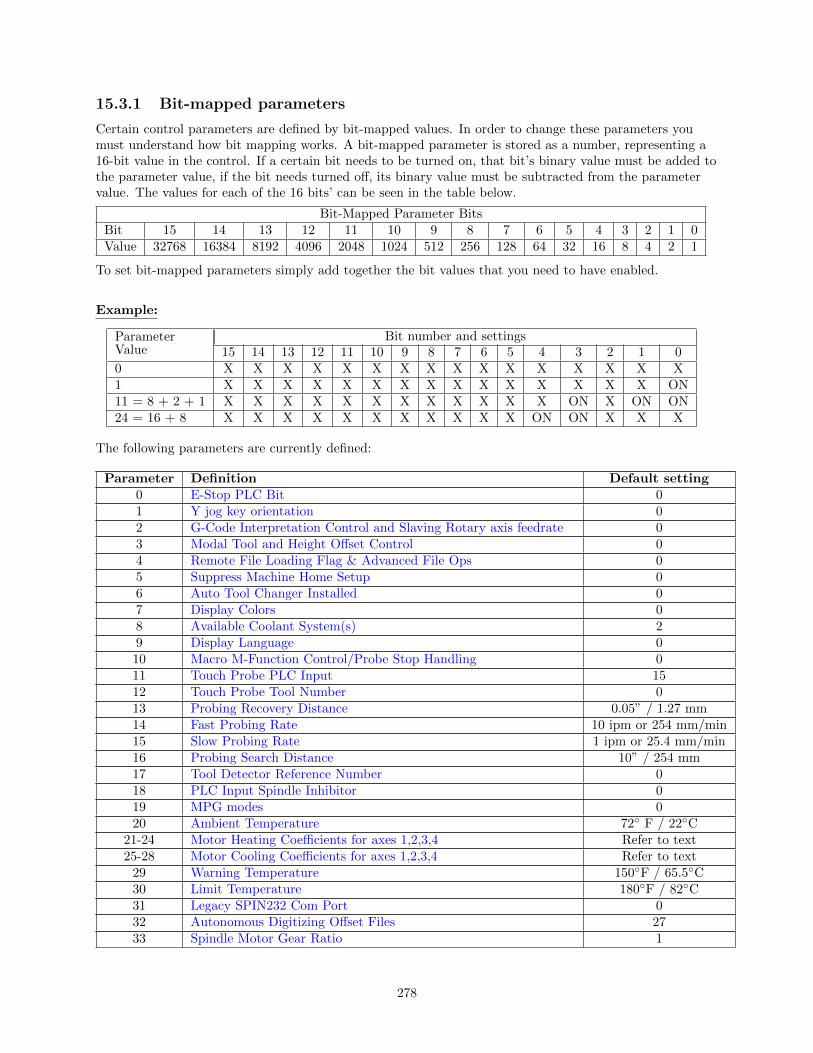
15.3.1 Bit-mapped parameters
Certain control parameters are defined by bit-mapped values. In order to change these parameters youmust understand how bit mapping works. A bit-mapped parameter is stored as a number, representing a16-bit value in the control. If a certain bit needs to be turned on, that bit’s binary value must be added tothe parameter value, if the bit needs turned off, its binary value must be subtracted from the parametervalue. The values for each of the 16 bits’ can be seen in the table below.
Bit-Mapped Parameter BitsBit 15 14 13 12 11 10 9 8 7 6 5 4 3 2 1 0Value 32768 16384 8192 4096 2048 1024 512 256 128 64 32 16 8 4 2 1
To set bit-mapped parameters simply add together the bit values that you need to have enabled.
Example:
ParameterValue
Bit number and settings15 14 13 12 11 10 9 8 7 6 5 4 3 2 1 0
0 X X X X X X X X X X X X X X X X1 X X X X X X X X X X X X X X X ON11 = 8 + 2 + 1 X X X X X X X X X X X X ON X ON ON24 = 16 + 8 X X X X X X X X X X X ON ON X X X
The following parameters are currently defined:
Parameter Definition Default setting0 E-Stop PLC Bit 01 Y jog key orientation 02 G-Code Interpretation Control and Slaving Rotary axis feedrate 03 Modal Tool and Height Offset Control 04 Remote File Loading Flag & Advanced File Ops 05 Suppress Machine Home Setup 06 Auto Tool Changer Installed 07 Display Colors 08 Available Coolant System(s) 29 Display Language 010 Macro M-Function Control/Probe Stop Handling 011 Touch Probe PLC Input 1512 Touch Probe Tool Number 013 Probing Recovery Distance 0.05” / 1.27 mm14 Fast Probing Rate 10 ipm or 254 mm/min15 Slow Probing Rate 1 ipm or 25.4 mm/min16 Probing Search Distance 10” / 254 mm17 Tool Detector Reference Number 018 PLC Input Spindle Inhibitor 019 MPG modes 020 Ambient Temperature 72◦ F / 22◦C
21-24 Motor Heating Coefficients for axes 1,2,3,4 Refer to text25-28 Motor Cooling Coefficients for axes 1,2,3,4 Refer to text
29 Warning Temperature 150◦F / 65.5◦C30 Limit Temperature 180◦F / 82◦C31 Legacy SPIN232 Com Port 032 Autonomous Digitizing Offset Files 2733 Spindle Motor Gear Ratio 1
278

Parameter Definition Default setting34 Spindle Encoder Counts/Rev 8,00035 Spindle Encoder Axis Number 036 Rigid Tapping Enable/Disable 037 Spindle Deceleration Time 1038 Multi-Axis Max Feedrate 039 Feedrate Override Knob Limit 12040 Basic Jog Increment 0.0001” / .001 mm41 Rotary Axis Jog Increment .01◦
42 Password for Configuration Menus 043 Automatic tool measurement options 044 TT1 PLC input number 045 WCS Lockout 046 Active G-Codes Display 048 Grid Digitize Patch Playback Z rapid clearance amount .1
49-51 Small Arc Feedrate Limiting 056 Feedrate Override Display Properties 057 Use Generic Load Meter Data from PLC 061 High Power Stall Timeout 0.562 High Power Stall PID Limit 11563 High Power Idle PID Multiplier 1.564 4th/5th Axis Pairing 0
65-67 Spindle Gear Ratios 1.068 Minimum Rigid Tapping Spindle Speed 069 Duration For Minimum Spindle Speed 1.070 Offset Library Inc/Decrement Amount .001” / .02 mm71 Part Setup Detector Height 072 Data Recording M-Function Options 073 Peck Drill Retract Amount 0.0574 M-Function executed at bottom of tapping cycle 475 Axis Summing Control 076 Manual Input Unrestricted Distance 077 Manual Input Movement Tolerance 078 Spindle Speed Display and Operations 079 Paired Axes Re-sync Delay Time 080 Voltage Brake Applied Message Frequency 081 Air Drill M-Function (executed instead of Z movement in drilling) -182 Spindle Drift Adjustment 083 Deep Hole Clearance Amount 0.0584 M-Function executed at return to initial point of tapping cycle 385 “Door Open” Interlock PLC bit 086 Rapid/Linear vector rate limit 0
87-90 Autotune Ka Performance parameters for axes 1,2,3,4 091-94 Axis Properties for axes 1,2,3,4 095-98 Autotune / Auto Delay Move Distance for axes 1,2,3,4 2” / 50.8 mm
99 Cutter Compensation Look-ahead 6100 Intercon comment generation 0101 Intercon clearance amount 0.1102 Intercon spindle coolant delay 3.0103 Intercon corner federate override 50.0104 Intercon modal line parameters 0105 Intercon modal arc parameters 0
279

Parameter Definition Default setting106 Intercon modal drilling cycle parameters 0115 Intercon Help 0116 A-Axis Y Coordinate 0117 A-Axis Z Coordinate 0118 B-Axis X Coordinate 0119 B-Axis Z Coordinate 0120 Probe stuck clearance amount 0.10” / 2.54 mm121 Grid digitize prediction minimum Z pullback 0.002” / .0508 mm122 Grid digitizing deadband move distance 0.0002” / .00508 mm123 Radial digitizing clearance move 0130 Z axis on/off selection 0131 4th axis on/off selection 0
132-135 Motor Heating Coefficients for axes 5,6,7,8 Refer to text136 G76 Fine Bore Retract Angle 0137 Load Meter Filter Size 0138 DRO Encoder Deadband 0139 Special Dwell between Moves 0140 Message log priority level 1141 Maximum message log lines 100142 Message log trim amount 100143 DRO properties (load meters, 4/5 digits, DTG) 0144 Comparison rounding 0145 Advanced macro properties (fast branching) 0146 Feed hold threshold for feed rate override 0147 Number of Messages in Operator Message Window 10148 Miscellaneous Jogging Options 0149 Spindle Speed Threshold 1.0150 Backplot Graphics display options 0151 Repeatability tolerance for probing 0154 Touchscreen options 0155 DSP Probe Installed 0
156-159 Autotune / Auto Delay Move Distance for axes 5,6,7,8 2” / 50.8 mm160 Enhanced ATC 0161 ATC Maximum Tool Bins 0162 Intercon M6 Initial M-Code 0164 ATC Feature Bit 0165 Acceleration/Deceleration Options 0
166-169 Axis Properties for axes 5,6,7,8 0170-177 PLC parameters 0
178 PLC I/O configuration (PLC program specific) 0179 Lube Pump Operation 0186 Probe Stuck retry disable 0187 Hard Stop Homing Power Limit 0
188-199 Aux key functions 0200-207 OPTIC4 Tach Volts Per RPM 0208-215 MPU Lash/Screw Comp Acceleration Coefficient 0.125
216 PC Based Lash Compensation on/off 0217 PC Based Screw Compensation on/off 0218 USB MPG Options 0219 Virtual Control Panel Options 0
220-231 Smoothing Parameters Refer to text
280

Parameter Definition Default setting236-239 Motor Cooling Coefficients for axes 5,6,7,8 0240-241 Rigid Tapping Decel and Stepsize 0252-255 Autotune Ka Performance parameters for axes 5,6,7,8 0
256 Drive Mode 0257 TT1 connection detection PLC input 0258 Velocity/Torque Mode override in Precision mode 0259 Manual Axis Designation 0260 Accelerated Graphics Backplot on/off 1
261-262 Precision Mode Standoff (Tolerance Percentage/Delay Time) 0265-266 BISS Encoder Options 0
270 Skew Correction: X Skew offset from Trusted/Intended X 0271 Skew Correction: Trusted/Intended Y 0278 Spindle Speed Display Precision 0
284-291 Brake Resistor Wattage for ACDC Drives 1-8 50300-307 Drive assignment to Axes 1-8 Refer to text308-315 Encoder assignment to Axes 1-8 Refer to text
316 Absolute Encoder Bits 0317 Single Turn Absolute Encoder Bits 0318 Five Axis Configuration 0323 MPU11 Encoder Speed Filter 0
324-331 Axis Boxcar size 0332-335 Encoder error suppression 0336-339 Motor torque estimation for velocity mode drives Refer to text340-347 Precision Mode delay (in milliseconds) for axes 1-8 0
348,351,354 MPG 1,2,3 Encoder Input 15, 0, 0349,352,355 MPG 1,2,3 Detents per Revolution 100350,353,356 MPG 1,2,3 Encoder Counts per Revolution 400
357-364 Axis Drive Max RPM 0365 Drive power-on delay 0.0366 Probe deceleration multiplier 2.0367 TT1 deceleration multiplier 2.0368 Autonomous Digitizing Angle Adjustment 4369 Tool Check Max Absolute Angle 0374 ACDC Drive Debug Log Axis Inclusion 0375 ACDC Drive Debug Log Size 0376 ACDC Drive Debug Log Collection Type 0377 ACDC Drive Debug Log Trigger Type 0378 ACDC Drive Debug Log Trigger Level 0379 ACDC Drive Debug Log Option 0
392-394 DP-7 parameters Refer to text395 Probing setup traverse speed 30 ipm or 762 mm/min396 Probing setup plunge speed 30 ipm or 762 mm/min398 Port/block mode 0399 AD1 arc chord tolerance adjustment .5400 Run Menu Cycle Start Enabled 0.0401 Forget Last Job Loaded 0.0411 Mpg Type 0
900-999 PLC program parameters –
281

15.3.2 Parameter 0 – E-Stop PLC Bit
This parameter specifies the PLC bit to which the physical Emergency Stop switch is connected. It ismainly used for ATC applications that use custom PLC messages. See table below for examples.
PLC Type ESTOP Input on PLC Parameter ValueGPIO4D Input 11 -11ALLINONE Input 11 -11OAK Input 11 -11RTK2/3/4 Input 11 -11PLCIO2 Input 11 -11DC3IO Input 11 -11Servo3IO Input 1 1
15.3.3 Parameter 1 – Y jog key orientation
This parameter is a 3-bit field where bit 0 is not used in the mill software. Bit 1 sets the direction ofmovement for the Y+ and Y- jog keys and bit 2 will swap the X and Y jog keys. This should always be setto 0 except for very special applications. Note: PLC program interaction is needed for these features.
Bit Function Description Parameter Value0 Not Used1 Flip direction of Y jog keys? Yes=2, No=02 Exchange X axis and Y-axis jog keys? Yes=4, No=0
15.3.4 Parameter 2 – G-code Interpretation Control and Slaving Rotary axisfeedrate
This parameter is a bit field that controls optional interpretation of several G-codes. The following tableshows the functions performed by the value entered in this parameter:
Bit Function Description Parameter Value0 Arc centers I, J, K are absolute in G90 mode? Yes = 1
No = 01 Allow Z being specified alone to be sufficient to trigger execution of a Yes = 2
canned tapping or drilling cycle to be executed? No = 02 Interpret dwell times associated with G4 , G74, G82, G84, and G89as Yes = 4
milliseconds rather than seconds? No = 03 Slaving rotary axis feedrate to non-rotary axis feedrate Yes = 8
Note that this feature has no effect for movement commands handled by No = 0Smoothing (when parameter 220=1).
4 Selects the center for scale, mirror and rotate. By default the center will Yes = 16be 0,0,0. Add 16 to this parameter to make the center of scale, mirror and No = 0rotate the current position.
5 Prevent rotary-only moves (rotary axis by itself on a line of G-code) from Yes = 32acquiring a remembered slaved rotary feedrate previously set by a No = 0previous line of G-code containing a rotary and non-rotary together.Note that this feature has no effect for movement commands handled bySmoothing (when parameter 220=1).
15.3.5 Parameter 3 – Modal Tool and Height Offset Control
282

Bit Meaning Parameter Value0 Tool and Height Offset numbers, T and H, will be reset upon job Reset upon job completion = 1,
completion (and not remain modal and active between jobs). Remain modal between jobs = 01 Reference tool position is set to Z home. Yes = 2 No = 02 Tool Height Offset Retention option. This option prevents the Turn on Tool Height Offset
current tool height offset from being turned off when the user enters Retention option = 4, No = 0the Tool Height Offset menu. Additionally, this option will causethe H height offset to be set to match the tool number when an AutoTool Change is performed (via F7 ATC) in the Offset Library.
15.3.6 Parameter 4 – Remote File Loading Flag & Advanced File Ops
This parameter controls the action of the Load Job menu when CNC job files are selected from drivesletters higher than C. These drives (i.e. drives D, E, F, etc.) are presumed to be network drives or extrahard drives.
Value Meaning0 Job files are not copied or cached. They are run from whichever drives they reside on.1 Job files are copied to the C drive (c:\cncm\ncfiles) when they are loaded. The local copy is used
when the job runs.2 Turn on file caching. Job files are temporarily cached on the C drive. The cached copy is used
while the job is running. The cached copy is deleted when the next job is loaded or whenParameter 4 changes to a 0 or 1.Digitize files are cached as the machine is digitizing. When digitizing is complete, the resultingfile is copied to the digitize directory specified in pathm.ini.
4 Set the Advanced File load menu as default for loading files8 Use Windows-style File Open dialogue
File caching is useful for machines with both a flash card and a hard drive. By caching job files from thehard drive on the flash card, the hard drive is not used while the job is running. As a result, the life of thehard drive is extended and the flash card does not fill up with job files.
15.3.7 Parameter 5 – Suppress Machine Home Setup
This parameter controls machine homing upon startup of the control. The following table details thefunctions controlled by this parameter:
Bit Function Description Parameter Value0 Suppress the requirement to set machine home before Yes = 1
running jobs? No = 01 Display router bit map at homing screen Yes = 2, No = 02 Disable stall detection when the CNC software first starts. Yes = 4, No = 0
Bit 0 suppresses the requirement to set machine home before running. If bit 0 of Parameter 5 is 0, machinehome must be set before jobs may be run. If bit 0 of Parameter 5 is 1, machine home is not requested orrequired, but Graphing and running of jobs will not work until the Z-axis is homed.
NOTE: Parameter 5 Bit 0 is separate from the ”Machine Home at Powerup” flag in the ControlConfiguration Screen. Parameter 5 Bit 0 determines whether you must home the machine; the ”MachineHome at Powerup” flag determines how you will home the machine, if you must do so.
15.3.8 Parameter 6 – Automatic Tool Changer Installed
This parameter tells the control whether an automatic tool changer installed on your machine. This fieldaffects the action of M6 in your CNC programs. See M6 for more information. It also affects whether the
283
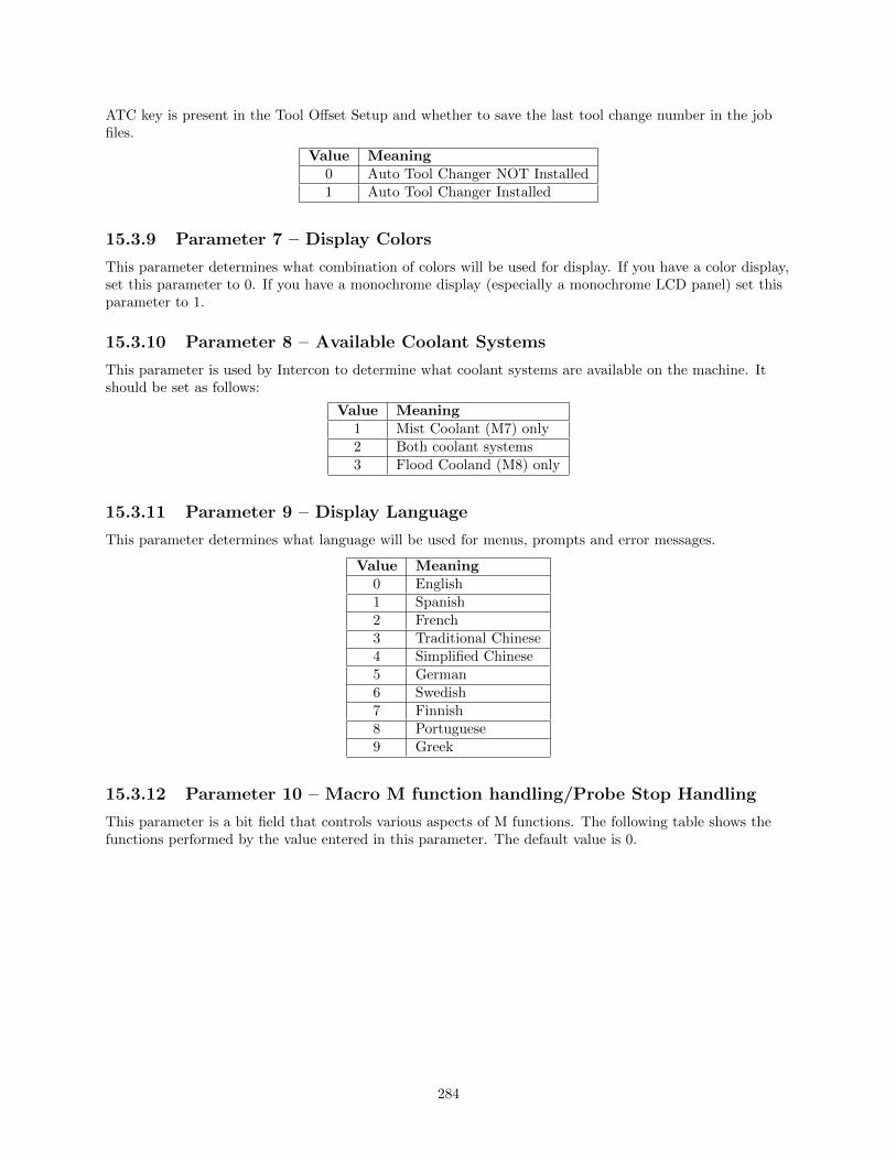
ATC key is present in the Tool Offset Setup and whether to save the last tool change number in the jobfiles.
Value Meaning0 Auto Tool Changer NOT Installed1 Auto Tool Changer Installed
15.3.9 Parameter 7 – Display Colors
This parameter determines what combination of colors will be used for display. If you have a color display,set this parameter to 0. If you have a monochrome display (especially a monochrome LCD panel) set thisparameter to 1.
15.3.10 Parameter 8 – Available Coolant Systems
This parameter is used by Intercon to determine what coolant systems are available on the machine. Itshould be set as follows:
Value Meaning1 Mist Coolant (M7) only2 Both coolant systems3 Flood Cooland (M8) only
15.3.11 Parameter 9 – Display Language
This parameter determines what language will be used for menus, prompts and error messages.
Value Meaning0 English1 Spanish2 French3 Traditional Chinese4 Simplified Chinese5 German6 Swedish7 Finnish8 Portuguese9 Greek
15.3.12 Parameter 10 – Macro M function handling/Probe Stop Handling
This parameter is a bit field that controls various aspects of M functions. The following table shows thefunctions performed by the value entered in this parameter. The default value is 0.
284

Bit Function Description Parameter Value0 Display M & G-codes in M function macros? Yes = 1, No = 01 Step through M function macros in Block Mode? Yes = 2, No = 02 Decelerate to stop on M105 and M106. With decel.set these moves take Decel = 4, Immediate
longer and are slightly less accurate. With immediate stop these moves are Stop = 0faster and more accurate; however the lack of controlled deceleration cancause excessive machine vibration.
3 Move to Z home on M6? No = 8, Yes = 04 (not used) Recommended value
This bit was previously used for controlling the type of deceleration to stop = 0on digitizing and probing moves. This functionality is now controlled byparameters 366 and 367.
15.3.13 Parameter 11 - DP4 PLC Input Number and Contact State
This parameter is used for the PLC input number that is used by the DP4 Touch Probe. Allowable rangeis a single value, +/- 1 to 240 and 50001 to 51312. A Positive number indicates Closed on contact and anegative number indicates Open on contact. A list of default settings for different console types are listedbelow.
Changing this parameter can cause damage to your probe. You shouldcontact your Dealer or Local Tech Representative before any modificationsare made.
Console Type/Model Input Number PLC Type/Model Input NumberM39 15 DC3IO 14M39s 14 RTK3 14M400 15 Servo3IO 2M400s 14 PLCIO2 15M15-10 2 15/15 15M400 ATC (RTK3) 14 RTK2 15M400 ATC (PLCIO2) 15 Koyo ATC 1MPU11 50769
15.3.14 Parameter 12 – Touch Probe Tool Number
This parameter is the tool number of the DP4 probe. Allowable range is 0 through 200. By default thevalue is 10. This is used to look up the length offset and tip diameter of the probe in the Tool OffsetLibrary.
15.3.15 Parameter 13 – Recovery Distance
This parameter is the distance that the probe moves off a surface after initial contact (only during probingcycles), before returning to the surface to take a recorded reading. For DSP Probes: This parameter isused for failed DSP windows. On a failed window, the DSP probe will retract this distance before retrying.
15.3.16 Parameter 14 – Fast Probing Rate
The fast probing rate is used for positioning moves and initial surface detection, and is determined by themachines response time and the permitted probe deflection. The default is 10 in/min. This is a veryconservative feedrate, in actual use 20 to 30 in/min is a good value and will not have any detrimentalimpact on accuracy in most cases.
285

15.3.17 Parameter 15 – Slow Probing Rate
The slow probing rate is used for the final measurement moves. The default setting is 1 in min. Thefollowing are some typical accuracy tolerances with the corresponding value set in parameter 15:
Probing Rate Accuracy0.5 in/min 12.7 mm/min 0.0001 in .00254 mm1 in/min 25.4 mm/min 0.0002 in .00508 mm1.5 in/min 38.1 mm/min 0.0005 in .0127 mm3.5 in/min 88.9 mm/min 0.0010 in .0254 mm18 in/min 457.2 mm/min 0.0050 in .1270 mm
15.3.18 Parameter 16 - Maximum Probing Distance
This is the maximum distance that the Boss and Web probing cycles “search” for a surface in a givendirection if no travel limits have been entered. The default setting is 10 inches. A larger value should beentered for the boss and web cycles if you are measuring very large features. These settings areconservative measurements and can be used initially for startup purposes. However, they can be changedto accommodate your work.
15.3.19 Parameter 17 – Detector Location Return Point
A non-zero value specifies the number of the reference return point (entered into the WCS menu) directlyabove a permanently mounted TT-1 tool detector. When the Auto function is called up in the tool offsetlibrary, the control will position the table to the return point specified by this parameter, and touch thetool off the TT-1 Tool detector.
Entry Return Point0 None1 G282 G303 G30P34 G30P4
A zero indicates that the tool detector is no permanently mounted; automatic tool measurement will beperformed without X/Y axis movement.
15.3.20 Parameter 18 – PLC Input Spindle Inhibit Parameter
This parameter stores the input for the Spindle Inhibit feature. A negative value must be entered if a”normally closed” probe is to be used with the control. A positive value must be entered if a ”normallyopen” probe is to be used with the control. The absolute value of Parameter 18 will directly reflect thePLC input the Spindle Inhibit is wired to. When this parameter is set, Digitizing and Probing cycles willnot run unless a probe or touch-off block is connected. This parameter is used to prevent the tool or probefrom crashing into the table. The default for this parameter is 0, which disables this feature.
286

PLC Type/Model Input NumberAllin1DC 50771MPU11 50771DC3IO/DC3IOB 15RTK3 15Servo3IO/M15DRV1 5PLCIO2 1015/15 10RTK2 10Koyo ATC 2
15.3.21 Parameter 19 – MPG modes
The MPG is a hand-held device that is used as an alternate way of jogging the machine. This parameterdefines the MPG’s mode of operation.
Bit Function Description Parameter Value2 Enable Z axis MPG* – This will allow the z- Yes = 4, No = 0
axis to be moved with the MPG whilerunning a job independent of the x and y axes
*PLC program interaction is needed for these features. The plc program is in direct control of MPGmodes. Z-axis MPG operation is not available with all controls.
15.3.22 Parameters 20–30 (also 132–135, 236–239) — Motor TemperatureEstimation
These parameters are used for motor temperature estimation. Parameters 20, 29 and 30 correspondrespectively to the ambient temperature of the shop, the overheating warning temperature, and the jobcancellation temperature, all in degrees Fahrenheit. Parameters 21-24 and 132-135 are the heatingcoefficients. Parameters 25-28 and 236-239 are the cooling coefficients.
To disable Motor Temperature Estimation for an axis, set its heating and cooling coefficients to 0. Forexample, to disable Motor Temperature Estimation for axis 1, set Parameter 21 to 0, and set Parameter 25to 0.
Note: Temperature estimation only applies to controls operating in Torque mode (i.e. DC brushed systemsand Centroid AC systems). MPU11 systems running in Velocity mode (i.e. third party drive systems) donot use this feature, and thus should be disabled (by setting all heating and cooling coefficients to 0).
Suggested values for AC Brushless Motors and DrivesSD SD3, SD1 SD3, SD1 SD3, SD1 SD1 45A SD1 45A
Drive 750 W 1, 2 KW (finned heatsink) (finned heatsink) (finned heatsink)motors motors 1, 2, KW motors 3 KW motors 4 KW motors
Parameters Axes Values Values Values Values Values21–24 1–4 0.23 0.5 0.23 0.23 0.23
132–135 5–8 0.23 0.5 0.23 0.23 0.2325–28 1–4 12.0 9.0 12.0 12.0 14.5
236–239 5–8 12.0 9.0 12.0 12.0 14.520 N/A 72 72 72 72 7229 N/A 150 150 150 150 15030 N/A 180 180 180 180 180
287
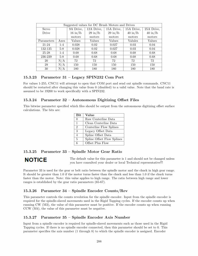
Suggested values for DC Brush Motors and DrivesServo 9A Drive, 12A Drive, 15A Drive, 15A Drive, 25A Drive,Drive 16 in/lb 29 in/lb 29 in/lb 40 in/lb 40 in/lb
motors motors motors motors motorsParameters Axes Values Values Values Valules Values
21-24 1-4 0.028 0.02 0.027 0.03 0.04132-135 5-8 0.028 0.02 0.027 0.03 0.0425-28 1-4 0.68 0.68 0.68 0.68 0.68
236-239 5-8 0.68 0.68 0.68 0.68 0.6820 N/A 72 72 72 72 7229 N/A 150 150 150 150 15030 N/A 180 180 180 180 180
15.3.23 Parameter 31 – Legacy SPIN232 Com Port
For values 1-255, CNC11 will attempt to open that COM port and send out spindle commands. CNC11should be restarted after changing this value from 0 (disabled) to a valid value. Note that the baud rate isassumed to be 19200 to work specifically with a SPIN232.
15.3.24 Parameter 32 – Autonomous Digitizing Offset Files
This bitwise parameter specified which files should be output from the autonomous digitizing offset surfacecalculations. The bits are:
Bit Value0 Raw Centerline Data1 Clean Centerline Data2 Centerline Flow Splines3 Legacy Offset Data4 Spline Offset Data5 Spline Offset Flow Splines6 Offset Plus Flow
15.3.25 Parameter 33 – Spindle Motor Gear Ratio
The default value for this parameter is 1 and should not be changed unlessyou have consulted your dealer or local Technical representative!!!
Parameter 33 is used for the gear or belt ratio between the spindle motor and the chuck in high gear range.It should be greater than 1.0 if the motor turns faster than the chuck and less than 1.0 if the chuck turnsfaster than the motor. Note: this value applies to high range. The ratio between high range and lowerranges is established by the gear ratio parameters (65-67).
15.3.26 Parameter 34 – Spindle Encoder Counts/Rev
This parameter controls the counts revolution for the spindle encoder. Input from the spindle encoder isrequired for the spindle-slaved movements used in the Rigid Tapping cycles. If the encoder counts up whenrunning CW (M3), the value of this parameter must be positive. If the encoder counts up when runningCCW (M4), the value of this parameter must be negative.
15.3.27 Parameter 35 – Spindle Encoder Axis Number
Input from a spindle encoder is required for spindle-slaved movements such as those used in the RigidTapping cycles. If there is no spindle encoder connected, then this parameter should be set to 0. Thisparameter specifies the axis number (1 through 8) to which the spindle encoder is assigned. Encoder
288

assignments are specified by parameters 308- 315. For example, if you decide to configure the 5th axis asthe spindle, and the spindle’s encoder is the 1st MPU11 onboard input encoder, then Parameter 35 (thisparameter) should be set to 5, and Parameter 312 should be set to 1.
15.3.28 Parameter 36 – Rigid Tapping Enable/Disable
This parameter is a bit field that enables or disables Rigid Tapping and its options. Bit Function
Bit Function Description Parameter Value0 Enable Rigid Tapping? Yes = 1, No = 01 Suppress sending ”Wait for Index Pulse” during Rigid Yes = 2, No = 0
Tapping?2 Allow Spindle Override during Rigid Tapping? Yes = 4, No = 03 Use Spindle Off system variable bit? Yes = 8, No = 0
(see note below) (see note below)4 What is the Spindle Encoder measuring? Spindle Encoder measures rotation
I.e. What is the physical mounting location of Spindle of spindle drive motor: value = 16,Encoder? Spindle Encoder measures rotation(see note below) of spindle head: value = 0
(see note below)5 Turn Off Spindle Following While At Bottom Of Yes = 32, No = 0
Hole. (NOT RECOMMENDED)
Note on Bit 3: This bit enables the spindle off system variable, for mpu11 systems. Most systems will notneed to set this bit. Mpu11 systems will not execute custom M5 macro commands during a rigid tap.Instead the software determines which bit, M3 or M4, to turn off to stop the spindle. Alternatively, settingbit 3 will cause the software to set the spindle off system variable bit, SV PC RIGID TAP SPINDLE OFF. Theplc program is then responsible for monitoring that bit and performing all actions in order to turn off thespindle.
Note on Bit 4: On machines where the Spindle Encoder is set up to measure the spindle drive motorrotation (Bit 4 = on, value 16), multi-pass Rigid Tapping and repeated Rigid Tapping down the same holecan only be done in the High Spindle Range. (See Parameters 33 and 65-67 for description of Spindle Gearranges/ratios.)
15.3.29 Parameter 37 – Spindle Deceleration Time ( Rigid TappingParameter)
This parameter is used in conjunction with parameter 36 when rigid tapping is enabled. This sets theamount of time required for the spindle to decelerate before it switches direction during a rigid tappingoperation.
15.3.30 Parameter 38 – Multi-Axis Max Feedrate
This parameter is used to limit the feedrate along all commanded move vectors. This parameter can beused to limit the speed of multi-axis moves on machines that may have enough power to move a single axisrapidly, but starve out of power on 2 or 3 axis rapid moves. A zero in this parameter will disable thisfeature. Note that this feature has no effect for movement commands handled by Smoothing (P220=1).
15.3.31 Parameter 39 – Feedrate Override Percentage Limit
This parameter is used for limiting the upper end of the Feedrate Override Knob percentage to a valuefrom 100% to 200%. This parameter can be used to restrict the Feedrate Override Knob effect on machineswith maximum rates over 200 in/min. The Feedrate Override Knob percentage is normally allowed to go to200%. However, on machines with high cutting speeds, if the knob is turned up to 200%, it createsovershoots on corners. If this parameter is set to something like 110, it will stop the Feedrate Override
289

Knob from exceeding 110% and thus causes the overshoots to disappear. The PLC program must checkthis parameter to actually enforce the limiting of Feedrate Override.
15.3.32 Parameter 40 – Basic Jog Increment
This parameter holds the basic jog increment for linear axes (0.0001” or 0.002 mm by default). This valueworks in conjunction with the x1, x10, and x100 jog keys to determine the amount to move a linear axisduring incremental jogging.
15.3.33 Parameter 41 – Rotary Axis Jog Increment
This parameter holds the jog increment for rotary axes (0.01◦ by default). This value works in conjunctionwith the x1, x10, and x100 jog keys to determine the amount to move a rotary axis during incrementaljogging.
15.3.34 Parameter 42 – Password for Configuration Menus
This parameter determines the password that the user must enter in order to gain full access to theconfiguration menus.
Value Meaning54.0 No password required for supervisor access; the user is not prompted for a passwordABCD.ABCD Password is 4 digits represented by ”ABCD” Example: for the password to be 1234,
set to 1234.1234Any other number Password is ”137”
15.3.35 Parameter 43 – Automatic tool measurement options
This parameter is a bit field that is used to configure properties of the TT1.
Bit Function Parameter Value0 The height of the tool detector (parameter 71) will be subtracted from
the measured height of the tool.Yes = 1; No = 0
1 Which PLC input to use for the Tool Z reference measurement. 0 = UseTouch Probe input in Parameter 11. 2 = Use TT1 input in Parameter44.
0 = Use Parameter 11.2 = Use Parameter 44.
2 Remind the operator to plug in the TT1 before doing Batch Tool Mea-suring.
Yes=4; No = 0
15.3.36 Parameter 44 – TT1 PLC input number
This parameter is the input number that the TT1 is wired into on the PLC. If a shared PLC input is usedfor the TT1 and the DP4 probe, then the value can be left at zero or set to the same value as parameter 11.
If you are using a different PLC input for the TT1 and DP4 when settingthe Z reference in the tool library with the DP4, make sure you don’t usea ruby probe tip. The TT1 is electrical continuity based and the ruby tipis not electrically conductive!
15.3.37 Parameter 45 — WCS Lockout
This parameter allows you to ”lock out” a WCS from editing if you do not want it’s values to change.Simply add the bit of the WCS you want locked out. For example, if you want to lock out WCS’s 1, 2, and5, you set the value of parameter 45 to 2(1−1) + 2(2−1) + 2(5−1) = 1 + 2 + 16 = 19. NOTE: G92 can still seta WCS even if it is locked out.
290

15.3.38 Parameter 46 — Active G-Codes Display
Set this parameter to 0 to always display the currently active G-codes in the bottom left corner of the mainscreen and MDI screen. Set it to 1 to display the G-codes only in MDI. Set it to 2 to disable the displaycompletely.
15.3.39 Parameter 48 – Grid Digitize Patch Playback Z rapid clearanceamount
This is the additional Z clearance amount higher than the Z surface level at which the original GridDigitizing operation was begun. The purpose of this value is to set the recorded starting “rapid to” Z levelof a Grid Digitize playback patch. In other words, the Z starting point of the first feedrate plunge move ofthe recorded patch is equal to the Z coordinate of the start of the original Grid Digitizing operation plusthe value of this parameter.
15.3.40 Parameters 49–51 — Small Arc Feedrate Limiting
These parameters are intended to control the federate limits of small-radius arc moves.
Parameter Function Description Input format49 Lower arc radius/federate limiting parameter rrrr.ffff, where rrrr is a radius threshold set-
ting, and .ffff is a federate adjustment setting50 Upper arc radius/federate limiting parameter RRRR.FFFF, where RRRR is a radius thresh-
old setting, and .FFFF is a federate adjust-ment setting
51 Arc Feedrate Limiting mode2 digit positive number.1’s digit (right digit) = Lower Limiting mode10’s digit (left digit) = Upper Limiting mode
The 2 digits in Parameter 51 can have the following values and associated meaning:
0 – Turn off Arc feedrate limiting for the associated radii range (default value)
1 – Literal Mode Feedrate limit = FFFF (.FFFF x 10000) for the associated radii range.
2 – Fractional Mode Feedrate limit = .FFFF x Programmed feedrate for the associated radii range
3 – Proportional Mode Feedrate limit = Arc radius x .FFFF x Programmed feerate for the associatedradii range.
The Lower Arc Limiting mode’s radii range includes any arc radius from 0 up to and including the rrrrsetting of Parameter 49. So, if you program a G2 or G3 arc with a radius of rrrr (of Parameter 49) or less,and the Lower Limiting mode in Parameter 51 is turned on, then the arc’s federate will be limitedaccording to how ffff (of Parameter 49) is interpreted. If the Control is set up in Millimeter mode, then rrrrspecifies the number of millimeters. However, if the Control is set up in Inch mode, then rrrr means thenumber of inches divided by 100.
The Upper Arc Limiting mode’s radii range includes any arc radius larger than the rrrr setting ofParameter 49 up to and including the RRRR setting of Parameter 50. So, if you program a G2 or G3 arcwith a radius of RRRR (of Parameter 50) or less, but greater than rrrr (of Parameter 49), and the UpperLimiting mode in Parameter 51 is turned on, then the arc’s federate will be limited according to how FFFF(of Parameter 50) is interpreted. If the Control is set up in Millimeter mode, then rrrr specifies the numberof millimeters. However, if the Control is set up in Inch mode, then rrrr means the number of inchesdivided by 100.
Note that if Parameter 51 contains values other than 00, 01, 02, 03, 10, 11, 12, 13, 20, 21, 22, 23, 30, 31,32, 33, it will be treated as invalid and will cause the Small Arc Feedrate Limiting feature to be disabled.
291

Also note that this feature has no effect for arc movement handled by Smoothing (P220=1).
Examples: (in millimeters)
Parameter 49 = 5.0050 (rrrr = 5 mm, ffff = 0050)Parameter 50 = 75.1500 (RRRR = 75 mm, FFFF = 1500)
If Parameter 51 = 31 and you program a G2 arc with a radius of 4 mm at a feedrate of 1000 mm min, thenthe actual feedrate of the arc will be lowered down to 50 mm/min.
If Parameter 51 = 23 and you program a G3 arc with a radius of 40 mm at a feedrate of 700 mm min, thenthe actual feedrate of the arc will be lowered down to 105 mm/min (=700 x .1500).
If Parameter 51 = 33 and you program a G3 arc with a radius of 72 mm at a feedrate of 1200 m/min, thenthe actual feedrate of the arc will remain at 1200 mm/min and will not be modified because it is wellwithin the Feedrate limit of 12960 mm/min (Arc radius x .FFFF x Programmed feerate = 72 x .1500 x1200 = 12960).
If Parameter 51 = 11 and you program a G2 arc with a radius of 100 mm at a feedrate of 2500 mm/min,then the actual feedrate of the arc will remain unmodified at 2500 mm/min because the arc radius isoutside both ranges specified by Parameters 49 and 50, and therefore this feature does not affect such arcs.
Examples: (in inches)
Parameter 49 = 50.0050 (rrrr = 1/2 inch, ffff = 0010)Parameter 50 = 200.1500 (RRRR = 2 inches, FFFF = 1500)If Parameter 51 = 31 and you program a G2 arc with a radius of 1/4 inch at a feedrate of 100 inches/min,then the actual feedrate of the arc will be lowered down to 10 inches per minute.
If Parameter 51 = 23 and you program a G3 arc with a radius of 1.5 inches at a feedrate of 200 inches/min,then the actual feedrate of the arc will be lowered down to 30 inches/min (=200 x .1500).
If Parameter 51 = 33 and you program a G3 arc with a radius of 1.75 inches at a feedrate of 300inches/min, then the actual feedrate of the arc will be lowered down to 78.75 inches/min (= Arc radius x.FFFF x Programmed feerate = 1.75 x .1500 x 300).
If Parameter 51 = 11 and you program a G2 arc with a radius of 3 inches at a feedrate of 250 inches/min,then the actual feedrate of the arc will remain unmodified at 250 inches/min because the arc radius isoutside both ranges specified by Parameters 49 and 50, and therefore this feature does not affect such arcs.
15.3.41 Parameter 56 — Feedrate Override Display Propertiexs / InverseTime Interpolation
Bits 1 and 2 define how the federate override is displayed in the status window. Bit 3 selects the meaningof inverse time feedrates (F) when inverse time mode (G93) is active. Bit 0 is unused.
Bit Function Parameter Value0 Not used1 Display programmed rate not actual 2 = Yes; 0 = No2 Display a bar meter of percentage 4 = Yes; 0 = No3 Inverse time meaning of F 8 = F is in inverse seconds, 0 = F is in inverse minutes
15.3.42 Parameter 57 — Use Generic Load Meter Data from PLC
If load meters are enabled (via parameter 143) the data being displayed for each axis is normally calculatedfrom its PID output (either real or simulated). However, if any axis has its corresponding bit set in thisparameter, then the data going into the load meter will come from the PLC system variables SV METER 1
292

- SV METER 8 (corresponding to axes 1-8). Furthermore, if an axis is a spindle axis (as set by parameter35) the load meter data will be displayed on the spindle override meter in the Status Window.
Cooperation from the PLC program is required for this feature to work. The PLC program needs to sendback a value between 0.0 and 100.0 via floating point system variables SV METER 1 - SV METER 8(corresponding to axes 1- 8). Note that there is future support for SV METER 9 up to SV METER 16,but for now there is support for up to only 8 axes.
15.3.43 Parameters 61 – 62 — Stall Detection Parameters
The M-Series control will detect and report several stall conditions. The low power stall occurs if thecontrol has been applying a specified minimum current for a specified time, and no encoder motion hasbeen detected. This may indicate a loose or severed encoder cable. A high power stall occurs if the controlhas been applying at least 90% current for a specified time, and no motion greater than 0.0005” has beendetected. This may indicate a physical obstruction. Note that this feature will only work with torque modedrives and not velocity mode drives.
Parameter 61 is the time limit, in seconds, for a high power stall. The default is 0.5 seconds. Parameter 62is the PID output threshold for a high power stall. The default is 115.
15.3.44 Parameter 63 — High Power Idle PID Multiplier
This parameter holds the value of a constant used for motor high power idle detection when an axis is notmoving and no job is running, but there is power going into the motor to maintain its position. The defaultvalue is 1.5. This is intended for early detection of an axis if it’s stopped against some abnormal resistanceor not tuned correctly, such that it will probably overheat later.
15.3.45 Parameter 64 — Fourth/Fifth Axis Pairing
This feature enables the 4th and 5th axes to be paired together or individually be run in a slaved statewith any of the other axes. This is intended to drive 2 screws on opposite sides of a table (probably arouter table or gantry system). Set this parameter to 0 (default) to indicate that no other axis is pairedwith the 4th or 5th axis. In order to pair both the 4th and 5th axes on the same system add the 4th axisvalue with the 5th axis value. Example: 4th axis paired with the Xaxis and 5th axis paired with the Z-axisa value of 49 would be entered into parameter 64. The axes are slaved upon power up but it is still possibleto move the paired (4th or 5th) axis independently if the axis is labeled.*NOTE: You cannot run Autotune on paired axes.
Value Meaning0 No Pairing (Default)1 Pair 4th axis with 1st Axis2 Pair 4th axis with 2nd Axis3 Pair 4th axis with 3rd Axis16 Pair 5th axis with 1st Axis32 Pair 5th axis with 2nd Axis48 Pair 5th axis with 3rd Axis64 Pair 5th axis with 4th Axis
15.3.46 Parameters 65 – 67 — Spindle Gear Ratios
These parameters tell the control the gear ratios for a multi-range spindle drive. Up to four speed rangesare supported; high range is the default. Parameters 65-67 specify the gear ratio for each lower range,relative to high range. For example, if the machine is a mill with a dual range spindle, and the spindle inlow range turns 1/10 the speed it turns in high range, then parameter 65 should be set to 0.1. Note that
293
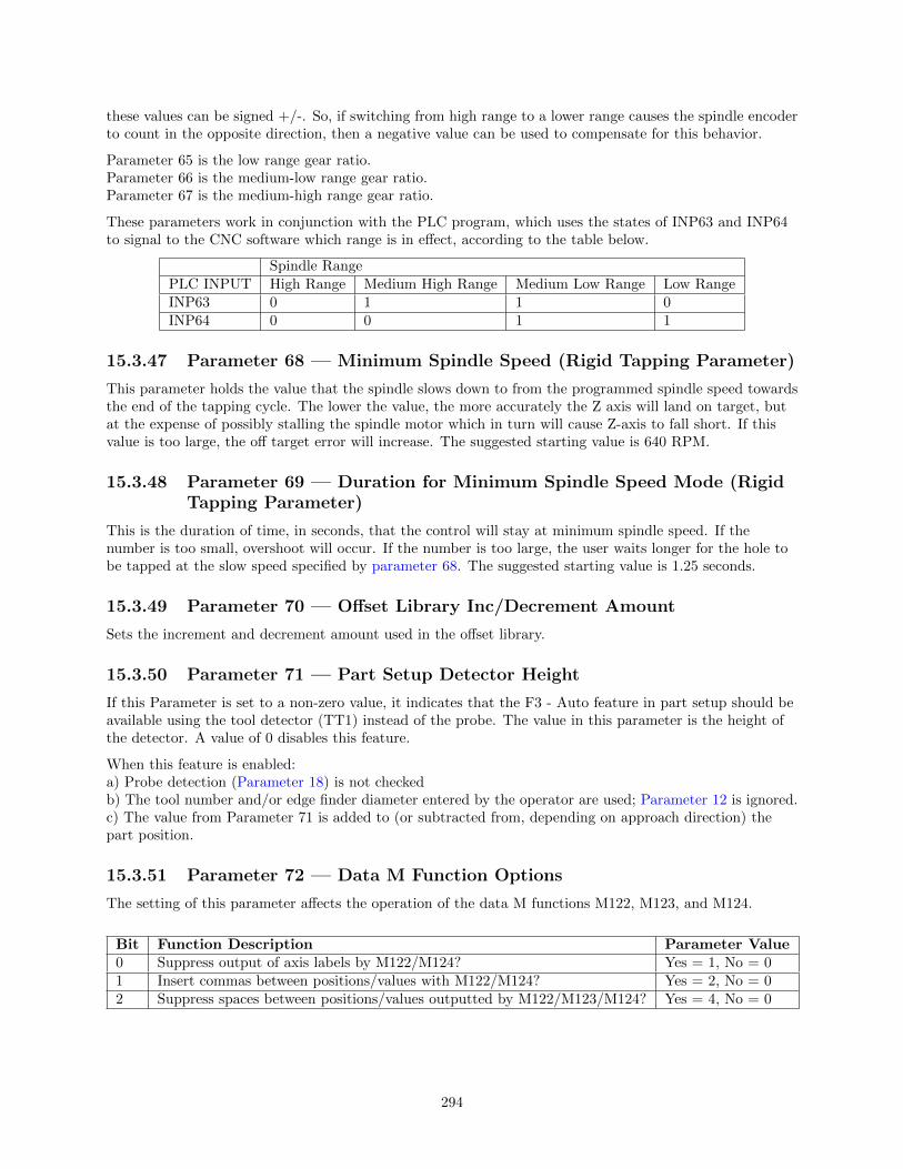
these values can be signed +/-. So, if switching from high range to a lower range causes the spindle encoderto count in the opposite direction, then a negative value can be used to compensate for this behavior.
Parameter 65 is the low range gear ratio.Parameter 66 is the medium-low range gear ratio.Parameter 67 is the medium-high range gear ratio.
These parameters work in conjunction with the PLC program, which uses the states of INP63 and INP64to signal to the CNC software which range is in effect, according to the table below.
Spindle RangePLC INPUT High Range Medium High Range Medium Low Range Low RangeINP63 0 1 1 0INP64 0 0 1 1
15.3.47 Parameter 68 — Minimum Spindle Speed (Rigid Tapping Parameter)
This parameter holds the value that the spindle slows down to from the programmed spindle speed towardsthe end of the tapping cycle. The lower the value, the more accurately the Z axis will land on target, butat the expense of possibly stalling the spindle motor which in turn will cause Z-axis to fall short. If thisvalue is too large, the off target error will increase. The suggested starting value is 640 RPM.
15.3.48 Parameter 69 — Duration for Minimum Spindle Speed Mode (RigidTapping Parameter)
This is the duration of time, in seconds, that the control will stay at minimum spindle speed. If thenumber is too small, overshoot will occur. If the number is too large, the user waits longer for the hole tobe tapped at the slow speed specified by parameter 68. The suggested starting value is 1.25 seconds.
15.3.49 Parameter 70 — Offset Library Inc/Decrement Amount
Sets the increment and decrement amount used in the offset library.
15.3.50 Parameter 71 — Part Setup Detector Height
If this Parameter is set to a non-zero value, it indicates that the F3 - Auto feature in part setup should beavailable using the tool detector (TT1) instead of the probe. The value in this parameter is the height ofthe detector. A value of 0 disables this feature.
When this feature is enabled:a) Probe detection (Parameter 18) is not checkedb) The tool number and/or edge finder diameter entered by the operator are used; Parameter 12 is ignored.c) The value from Parameter 71 is added to (or subtracted from, depending on approach direction) thepart position.
15.3.51 Parameter 72 — Data M Function Options
The setting of this parameter affects the operation of the data M functions M122, M123, and M124.
Bit Function Description Parameter Value0 Suppress output of axis labels by M122/M124? Yes = 1, No = 01 Insert commas between positions/values with M122/M124? Yes = 2, No = 02 Suppress spaces between positions/values outputted by M122/M123/M124? Yes = 4, No = 0
294

15.3.52 Parameter 73 — Peck Drill Retract Amount (Canned CycleParameter)
This specifies the retract amount used during a G73 peck drilling cycle.
15.3.53 Parameter 74 — M-function executed at bottom of tapping cycle(Canned Cycle Parameter)
This specifies the number of the M-function that is executed at the bottom of the G84 tapping cycle(primarily used for reversing the spindle in preparation for pulling out of the tap hole). This also specifiesthe number of the M-function that is executed after the G74 countertapping cycle is done (returned to theinitial point).
15.3.54 Parameter 75 — Summing Control
This parameter controls the type of position to be summed (local or machine), and which axes are to besummed together and which axis will bear the effects of the the summing. The parameter can contain upto four digits. The sign of the parameter value and the position and value of each digit has specialsignificance as indicated in the tables below:
Sign Position Type
+SumMachineCoordinates
-SumLocalCoordinates
Parameter DigitPosition
SummedAxis
1’s Col. Axis 110’s Col. Axis 2100’s Col. Axis 31,000’s Col. Axis 4
Digit Value Meaning0 Summing off1 through 4 Axis to Sum with5 (Reserved)6 Disable display7 Display if moved8 Display if other moves9 (Reserved)
The ”Summed Axis” is the axis that bears the position sum of itself with the ”Axis to Sum with”. TheDRO display of the ”Summed Axis” will show this summed position. The DRO will display both labelswhen displaying a summed axis. Furthermore, G-codes that command movement on the ”Summed Axis”will have their positions offset by the position of the ”Axis to Sum with”.
It is highly recommended that summing be done with Local Coordinates(using the ‘-’ sign in the parameter value). Summing with MachineCoordinates can cause the effective software travel limits to move, thusresulting in physical overtravel or severely handicapping the amount ofavailable travel, due to the fact that software travel limits are defined interms of Machine Coordinates. Summing with Local Coordinates avoidsthis problem.
Here are some examples:
Desired Display ParameterAxis 3 DRO will display the result of axis 3 and 4 machine coordinate positionssummed together.
400
Axis 4 DRO will display the result of axis 4 and 3 local coordinate positionssummed together. Machine coordinate positions are not affected.
-3000
Axis 3 DRO will display the result of axis 3 and 4 local coordinate positionssummed together. Axis 4 DRO display will be disabled.
-6400
Axis 4 DRO will display the result of axis 4 and 3 local coordinate positionssummed together. Axis 3 DRO display will be disabled.
-3600
Axis 3 DRO will display the result of axis 3 and 4 local coordinate positionssummed together. Axis 4 will be displayed only if it moves.
-7400
295
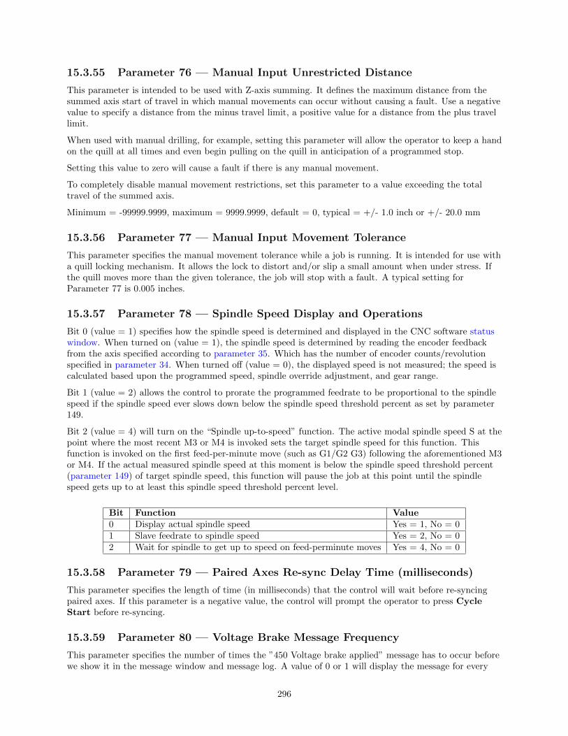
15.3.55 Parameter 76 — Manual Input Unrestricted Distance
This parameter is intended to be used with Z-axis summing. It defines the maximum distance from thesummed axis start of travel in which manual movements can occur without causing a fault. Use a negativevalue to specify a distance from the minus travel limit, a positive value for a distance from the plus travellimit.
When used with manual drilling, for example, setting this parameter will allow the operator to keep a handon the quill at all times and even begin pulling on the quill in anticipation of a programmed stop.
Setting this value to zero will cause a fault if there is any manual movement.
To completely disable manual movement restrictions, set this parameter to a value exceeding the totaltravel of the summed axis.
Minimum = -99999.9999, maximum = 9999.9999, default = 0, typical = +/- 1.0 inch or +/- 20.0 mm
15.3.56 Parameter 77 — Manual Input Movement Tolerance
This parameter specifies the manual movement tolerance while a job is running. It is intended for use witha quill locking mechanism. It allows the lock to distort and/or slip a small amount when under stress. Ifthe quill moves more than the given tolerance, the job will stop with a fault. A typical setting forParameter 77 is 0.005 inches.
15.3.57 Parameter 78 — Spindle Speed Display and Operations
Bit 0 (value = 1) specifies how the spindle speed is determined and displayed in the CNC software statuswindow. When turned on (value = 1), the spindle speed is determined by reading the encoder feedbackfrom the axis specified according to parameter 35. Which has the number of encoder counts/revolutionspecified in parameter 34. When turned off (value = 0), the displayed speed is not measured; the speed iscalculated based upon the programmed speed, spindle override adjustment, and gear range.
Bit 1 (value = 2) allows the control to prorate the programmed feedrate to be proportional to the spindlespeed if the spindle speed ever slows down below the spindle speed threshold percent as set by parameter149.
Bit 2 (value = 4) will turn on the “Spindle up-to-speed” function. The active modal spindle speed S at thepoint where the most recent M3 or M4 is invoked sets the target spindle speed for this function. Thisfunction is invoked on the first feed-per-minute move (such as G1/G2 G3) following the aforementioned M3or M4. If the actual measured spindle speed at this moment is below the spindle speed threshold percent(parameter 149) of target spindle speed, this function will pause the job at this point until the spindlespeed gets up to at least this spindle speed threshold percent level.
Bit Function Value0 Display actual spindle speed Yes = 1, No = 01 Slave feedrate to spindle speed Yes = 2, No = 02 Wait for spindle to get up to speed on feed-perminute moves Yes = 4, No = 0
15.3.58 Parameter 79 — Paired Axes Re-sync Delay Time (milliseconds)
This parameter specifies the length of time (in milliseconds) that the control will wait before re-syncingpaired axes. If this parameter is a negative value, the control will prompt the operator to press CycleStart before re-syncing.
15.3.59 Parameter 80 — Voltage Brake Message Frequency
This parameter specifies the number of times the ”450 Voltage brake applied” message has to occur beforewe show it in the message window and message log. A value of 0 or 1 will display the message for every
296

instance that it occurs.
15.3.60 Parameter 81 — Air Drill M-function (Canned Cycle Parameter)
P81 (when not equal to –1.0) specifies the M-function to be called in place of Z-axis movement during aG81 drilling cycle.
15.3.61 Parameter 82 — Spindle Drift Adjustment (Rigid Tapping Parameter)
This value is the number of degrees that the spindle will take to coast to a stop, when the spindle is turnedoff at the minimum spindle speed specified by parameter 68.
15.3.62 Parameter 83 — Deep Hole clearance amount (Canned CycleParameter)
Parameter 83 specifies the clearance amount used during a G83 deep hole drilling cycle.
15.3.63 Parameter 84 — M function executed at a return to initial point oftapping cycle (Canned Cycle Parameter)
This specifies the number of the M-function that is executed after the G84 tapping cycle is done (returnedto the initial point). This also specifies the number of the M-function that is executed at the bottom of theG74 countertapping cycle (to reverse the spindle in preparation for pulling out of the countertap hole).
15.3.64 Parameter 85 — ”Door Open” Interlock PLC Bit
This parameter provides a way for a system integrator to implement a safety interlock that limits rate ofmovement when the doors are open. This parameter specifies the PLC bit number and PLC bit polaritythat indicates the ”door open” condition. If the specified PLC bit is in the specified “door open” condition,then all normal movement commands will be limited to the slow jog rate (as specified in the JogParameters menu in Machine Configuration). Polarity of the “door open” condition is specified thuswise: apositive number indicates that the “door open” condition occurs when the specified PLC bit is On, and anegative number indicates that the “door open” condition occurs when the specified PLC bit is Off. If thisparameter is set to 0 (the default value), then this feature is disabled, and no checking for a “door open”condition is done. Note that this feature has no effect for movement commands handled by Smoothing(P220=1). Also note that PLC program interaction is needed for this feature to work.
15.3.65 Parameter 86 — Rapid/Linear vector rate limit
This parameter controls the feature that imposes a limit on the number of rapid and/or linear moves persecond to the value specified in this parameter. If the value of this parameter is more than 0, Rapid and/orLinear moves will be combined to prevent the aforementioned limit from being exceeded. This parameter isused for testing purposes and should be set to 0 to disable this feature. Note that this feature has no effectfor movement commands handled by Smoothing (P220=1).
15.3.66 Parameters 87 – 90 (and also 252 – 255) — Autotune Ka Performanceparameters
These parameters are used by autotune. Increasing the value will increase the Ka used by autotune whichwhen used will increase the PID used during acceleration. The default value is 0. The maximum value is50 and the minimum value is 0. Values for axes 1–4 are specified in parameters 87–90. Values for axes 5-8are specified in parameters 252–255.
297

15.3.67 Parameters 91 – 94 (and also 166 – 169) — Axis Properties
These parameters may be used to set various axis properties. Properties for axes 1 – 4 are specified inparameters 91 – 94. Properties for axes 5 – 8 are specified in parameters 166 – 169.
Bit Function Description Parameter Value0 Rotary/Linear Axis Selection Rotary Axis = 1, Linear Axis = 01 Rotary Display Mode Wrap Around = 2, Show Rotations = 02 Suppress direction check when doing Tool Check? Don’t Check = 4, Check = 03 Suppress park function? Don’t Park = 8, Park = 04 NOT USED ON MILL Recommended bit value is 05 Linear Display of Rotary Axis Linear Display = 32, Default Rotary = 06 4th Axis works like Z axis Yes = 64, No = 07 NOT USED ON MILL Recommended bit value is 08 Axis is triangular rotary? Yes = 256, No = 09 Hide axis display from DRO Yes = 512, No = 010 Triangular rotary axis type Articulated Head = 1024, Tilt Table = 011 Rotation Center is parallel to X? Yes = 2048, No = 012 NOT USED Recommended bit value is 013 NOT USED Recommended bit value is 014 Enable TWCS for Articulated Head machines Yes = 16384, No = 0
Bit 0: Turning this bit on will cause the DRO display for the affected axis to be displayed in degrees. Alsothis information is used by Intercon to make rotary axis support available (by setting parameter 94 to 1,indicating that the fourth axis is rotary). This bit is also used when performing inch/mm conversions:values for a rotary axis will not be converted since they are assumed to be in degrees regardless of thesystem of linear units.
Bit 1: This bit has no effect unless Bit 0 (mentioned above) is turned on. When this bit is turned on, a“Wrap Around” display is shown on the DRO. A “Wrap Around” Rotary Display is a display in degreeswithout the number of rotations shown. If this bit is turned off, the number of rotations away from 0degrees will be shown alongside the degree display.
Bit 2: This bit will only affect the Z-axis. It controls whether or not a direction check will be performedwhen the Tool Check button is pressed. If this bit is turned on, direction checking is turned off, and thus,there is a possibility for the Z-axis to move downward unexpectedly, depending on the Z value of ReturnPoint #1 (G28). Therefore, it is best in most cases to leave this bit turned off to allow direction checkingto be turned on (value = 0).
Bit 3: Setting this bit prevents ¡F1¿ (Park) in the Shutdown menu from parking this axis.
Bit 5: This setting overrides only the DRO display options for an axis that has bit 0 set (including theRotary Display Mode – bit 1) so that the display does not reflect a degree symbol or any indication of thenumber of rotations, but appears as a linear axis.
Bit 6: This bit only works for Parameter 94 (4th axis). Setting this bit will cause the 4th axis to respond toZ-axis only commands just like the Z-axis, for example issuing an M25 with this bit set will cause the Zand 4th axes to go the home (G28) position.
Bit 8: This setting is used in conjunction with bit 10. It only works for parameter 166 (5th axis). Settingthis bit on will identify this axis as a Triagular Rotary, which may either be an Articulated Head axis, or aTilt Table axis.
Bit 9: This setting will hide the affected axis from the DRO display. Note that this does not prevent suchan axis from being commanded to move.
Bit 10: In order for this setting to work, bit 8 must be turned on. This setting has meaning only forparameter 166 (5th axis). Setting this bit on will identify this axis as the controller of the angle of
298

articulation on an Articulated Head machine. If this bit is not set, then this axis will be identified as thecontroller of the tilt angle on a Tilt Table machine.
Bit 11: In order for this setting to work, bit 0 must be turned on (i.e. axis is rotary). Also, this setting onlyaffects axes 4 and higher. This setting indicates that this rotary axis is mounted in such a way so that itsrotation center line is parallel to the X axis (axis 1). The rotation center line’s machine coordinate locationis then defined by parameters 116 and 117. This setting enables backplot to display rotary movementsencircling the X axis and also gives the needed machine geometry information to G93.1 for it to properlycalculate the tool tip feedrate in 3D space in such a configuration.
Bit 14: This bit (in conjunction with the CSR unlock) enables the TWCS (Transformed WCS) feature forArticulated Head machines. When this feature is enabled, each individual WCS can be independently setup as either transformed or non-transformed using the TWCS=Yes/No setting in the WCS configurationscreen (See TWCS in Chapter 4). However, enabling this feature bit will always cause automatic B/5thaxis transformation on certain features regardless of the TWCS=Yes/No setting for each WCS. Suchfeatures are: Tool Check, M25, Digitizing, and the movements done in the Probing Cycles.
15.3.68 Parameters 95 – 98 (and also 156 – 159) — Autotune Move Distance/ Auto Delay Calculation Move Distance
These parameters hold the maximum distance that the control will move each axis in either direction fromthe starting point when either Autotune or Auto Delay Calculation is run. The default value for theseparameters is 2.0 inches. Values for axes 1 – 4 are specified in parameters 95 – 98. Values for axes 5 – 8 arespecified in parameters 156 – 159.
15.3.69 Parameter 99 — Cutter Compensation Look-ahead
This parameter sets the default number of line or arc events for the G-code interpreter to scan ahead whenCutter Compensation (G41 or G42) is active. Values of 1 to 99 are allowed for this parameter and defaultis 1.
15.3.70 Parameters 100 – 106 and 115 — Intercon parameters
These parameters are some of the Intercon setup parameters. See Chapter 10 for more information aboutthese parameters. Changing values will change Intercon settings and may affect the output of the G-codeprogram if it is reposted.
15.3.71 Parameter 116 — A-Axis Y Coordinate
This parameter is used in conjunction with Dig to CAD to export digitized data for use with CAD/CAMsoftware (see Chapter 8). It is used to define the Y coordinate of the center of rotation for a rotary axisthat rotates about the X-axis.
15.3.72 Parameter 117 — A-Axis Z Coordinate
This parameter is used in conjunction with Dig to CAD to export digitized data for use with CAD/CAMsoftware (see Chapter 8). It is used to define the Z coordinate of the center of rotation for a rotary axisthat rotates about the X-axis.
15.3.73 Parameter 118 — B-Axis X Coordinate
This parameter is used in conjunction with Dig to CAD to export digitized data for use with CAD/CAMsoftware (see Chapter 8). It is used to define the X coordinate of the center of rotation for a rotary axisthat rotates about the Y-axis.
299

15.3.74 Parameter 119 — B-Axis Z Coordinate
This parameter is used in conjunction with Dig to CAD to export digitized data for use with CAD/CAMsoftware (see Chapter 8). It is used to define the Z coordinate of the center of rotation for a rotary axisthat rotates about the Y-axis.
15.3.75 Parameter 120 — Probe Stuck Clearance Amount
This parameter specifies the distance that digitizing or probing functions will move to try to clear a stuckprobe condition. A stuck probe condition exists when the probe detects a point and then moves away butthe probe input has not changed. It is recommended that this parameter should not be changed from itsdefault value without consulting a qualified technician.
15.3.76 Parameter 121 — Grid digitize prediction minimum Z pullback
This parameter specifies the minimum distance the Z-axis will move upward when pulling back from asurface. The digitizing function attempts to predict the slope of a part surface because time is saved whenthe Z-axis does not have to travel upward to the starting Z depth for every digitized point. When probecontact is made traversing in the XY plane, this parameter specifies the minimum distance the Z-axismoves upward before attempting another XY plane move. Smaller values are better when the surface beingdigitized has smooth curves. Larger values are better for surfaces that have steep walls. It is recommendedthat this parameter should not be changed from its default value without consulting a qualified technician.
15.3.77 Parameter 122 — Grid digitizing deadband move distance
This parameter specifies a deadband distance used for internal calculations when doing a clearance move.It is recommended that this parameter should not be changed from its default value.
15.3.78 Parameter 123 — Radial Clearance Move
This parameter only applies to radial digitizing and determines what type of positioning move thedigitizing probe will make should it encounter an unexpected probe contact with the surface of the partduring Radial Digitizing. Unexpected probe contact is defined as probe contact occurring while the probeis traversing towards the user defined center point.
With Parameter 123 set to 0: When the probe encounters an unexpected probe contact, the digitizingprogram stops data collection. The control then prompts the operator to jog the probe to a clear position.This can be any place inside the digitizing radius and above the part, that the probe stylus has a clearpath to the defined center position. To restart data collection press Cycle Start. The probe moves in theXY plane from the position the operator placed it at, to the center position defined in the radial setupmenu. After reaching the center position, the probe will feed down to the Zaxis position it was at when thedata collection was interrupted. The digitizing run will resume with the probe approaching from thedefined center position.
With Parameter 123 set to 1: When the probe encounters an unexpected probe contact, it willautomatically move (with probe detection turned off) to the maximum Z height, then moves the X andY-axis to the defined center position. The probe will then move to the Z position it was at when theunexpected contact occurred. It will then move from the defined center position, towards the measurementposition it was trying to approach when the unexpected probe contact occurred and continue digitizing.
With Parameter 123 set to 2: When the probe encounters an unexpected probe contact, it willautomatically move back to the defined center position (with probe detection turned off), at its present Zheight. It will then move from the defined center position, towards the measurement position it was tryingto approach when the unexpected probe contact occurred and continue digitizing.
300
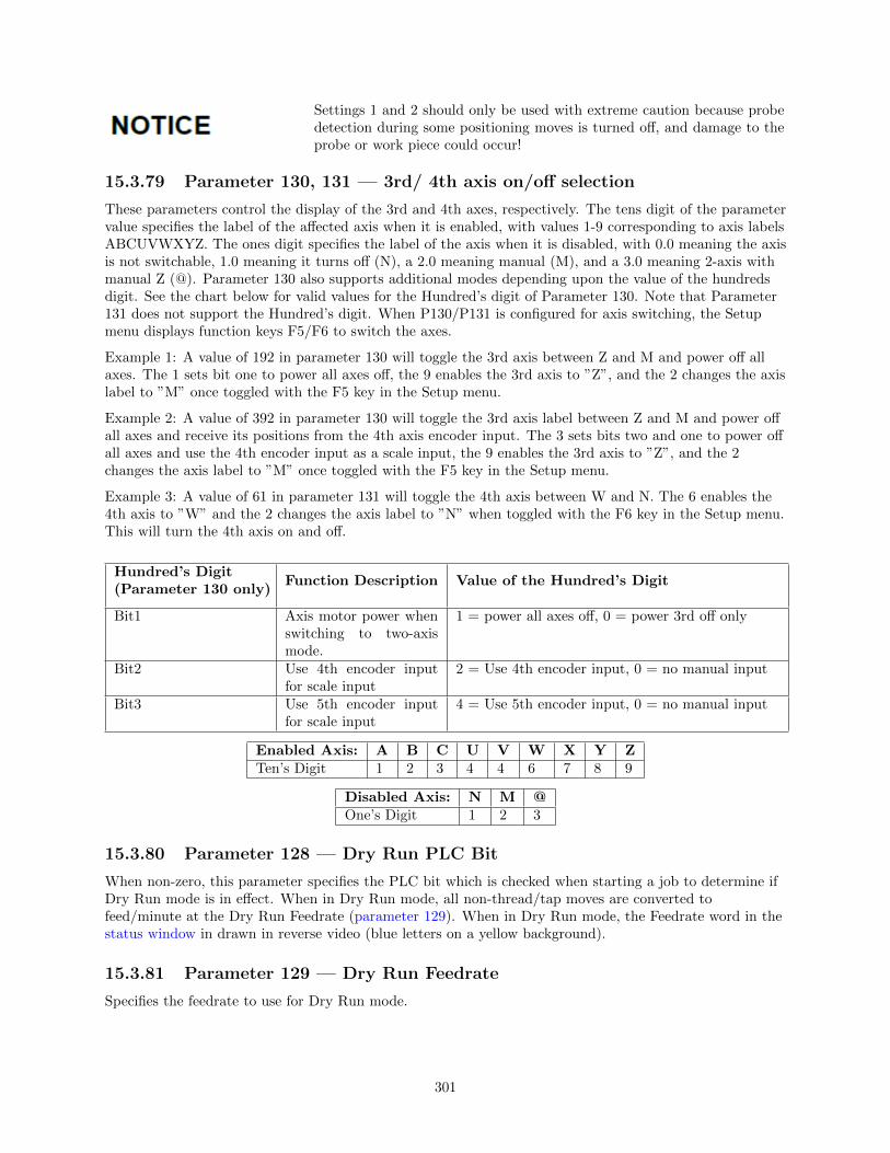
Settings 1 and 2 should only be used with extreme caution because probedetection during some positioning moves is turned off, and damage to theprobe or work piece could occur!
15.3.79 Parameter 130, 131 — 3rd/ 4th axis on/off selection
These parameters control the display of the 3rd and 4th axes, respectively. The tens digit of the parametervalue specifies the label of the affected axis when it is enabled, with values 1-9 corresponding to axis labelsABCUVWXYZ. The ones digit specifies the label of the axis when it is disabled, with 0.0 meaning the axisis not switchable, 1.0 meaning it turns off (N), a 2.0 meaning manual (M), and a 3.0 meaning 2-axis withmanual Z (@). Parameter 130 also supports additional modes depending upon the value of the hundredsdigit. See the chart below for valid values for the Hundred’s digit of Parameter 130. Note that Parameter131 does not support the Hundred’s digit. When P130/P131 is configured for axis switching, the Setupmenu displays function keys F5/F6 to switch the axes.
Example 1: A value of 192 in parameter 130 will toggle the 3rd axis between Z and M and power off allaxes. The 1 sets bit one to power all axes off, the 9 enables the 3rd axis to ”Z”, and the 2 changes the axislabel to ”M” once toggled with the F5 key in the Setup menu.
Example 2: A value of 392 in parameter 130 will toggle the 3rd axis label between Z and M and power offall axes and receive its positions from the 4th axis encoder input. The 3 sets bits two and one to power offall axes and use the 4th encoder input as a scale input, the 9 enables the 3rd axis to ”Z”, and the 2changes the axis label to ”M” once toggled with the F5 key in the Setup menu.
Example 3: A value of 61 in parameter 131 will toggle the 4th axis between W and N. The 6 enables the4th axis to ”W” and the 2 changes the axis label to ”N” when toggled with the F6 key in the Setup menu.This will turn the 4th axis on and off.
Hundred’s Digit(Parameter 130 only)
Function Description Value of the Hundred’s Digit
Bit1 Axis motor power whenswitching to two-axismode.
1 = power all axes off, 0 = power 3rd off only
Bit2 Use 4th encoder inputfor scale input
2 = Use 4th encoder input, 0 = no manual input
Bit3 Use 5th encoder inputfor scale input
4 = Use 5th encoder input, 0 = no manual input
Enabled Axis: A B C U V W X Y ZTen’s Digit 1 2 3 4 4 6 7 8 9
Disabled Axis: N M @One’s Digit 1 2 3
15.3.80 Parameter 128 — Dry Run PLC Bit
When non-zero, this parameter specifies the PLC bit which is checked when starting a job to determine ifDry Run mode is in effect. When in Dry Run mode, all non-thread/tap moves are converted tofeed/minute at the Dry Run Feedrate (parameter 129). When in Dry Run mode, the Feedrate word in thestatus window in drawn in reverse video (blue letters on a yellow background).
15.3.81 Parameter 129 — Dry Run Feedrate
Specifies the feedrate to use for Dry Run mode.
301

15.3.82 Parameters 132–135 — Motor Heating Coefficients for axes 5-8
See parameters 20-30 for more information.
15.3.83 Parameters 136 — G76 Fine Bore Retract Angle
0-360 Degrees. A setting of 0 = Retract in Y+ direction.
15.3.84 Parameters 137 — Load Meter Filter Size
This controls the number of samples used in calculating an average output for the load meter display, as away of smoothing it out.
15.3.85 Parameters 138 — DRO Encoder Deadband
This controls the deadband amount (in encoder counts) used by the anti-flicker DRO filter.
15.3.86 Parameter 139 — Special Dwell between Moves
This parameter turns on and specifies the amount dwell time between moves, with exceptions in specialcases. This parameter is similar to specifying a G61 (Modal Decel and Stop) at the beginning of a CNCprogram, except that dwelling will not happen under certain conditions: (1) No dwell will happen between2 arcs. (2) No dwell will happen if before the move that contains Z movement.
15.3.87 Parameter 140 — Message log priority level
This parameter controls the messages that are written to the message log, which can be accessed throughthe F9 - Logs function in the Utilities menu. See Chapter 15 for the list of numbered messages. Messagelogging can be disabled be setting this parameter to -1. The recommended log level is 4.
Value Which numbered messages are logged-1 None1 Numbered messages 0-299 and 400-499 – The most serious faults.4 Numbered messages 0-299 and 400 and higher – The most serious faults and medium severity errors.9 All numbered messages
15.3.88 Parameter 141 — Maximum message log lines
This parameter is the number of lines that will be kept in the message log. If this parameter is set to10,000, for example, the newest 10,000 messages will be retained. The CNC software will delete the oldestmessages, trimming the log file to the given number of lines at startup and periodically while the CNCsoftware is in an idle state. Parameter 142 controls the frequency of the log cleanup.
15.3.89 Parameter 142 — Message log trim amount
This parameter is the number of additional lines above the minimum that can be added to the log before itis reduced to the minimum size. Setting this parameter to a lower value will cause the log file to betrimmed to its minimum size more often. The higher the value, the less often the log will be trimmed. Thespeed of the disk drive and total size of the log file at the time it is trimmed will determine how long thelog cleanup takes. Under most circumstances, using 10,000 and 1,000 for parameters 141 and 142 willprovide a reasonable and useful log size with no noticeable effects on performance. If parameters 141 and142 are set to excessively high values, the message ”Trimming excess lines from log file” will be presented.This message will appear at startup and very infrequently when the CNC software is idle. Normaloperation can proceed after the message disappears. If the delay is unacceptable, reduce the values ofparameters 141 and 142.
302

15.3.90 Parameter 143 — DRO Properties (load meters, 4/5 digits, DistanceTo Go)
This parameter controls the display of the axis load meters and 4/5 digit DRO precision.
Bit Function Description Parameter Value0 Enable Load Meters Enable = 1, Disable = 01 Load Meter Outline Enable = 2, Disable = 02 DRO 4/5 Digit Precision 5 digits = 4, 4 digits = 03 Mini DRO (Distance to Go) Enable = 8, Disable = 0
Add the values of the desired properties. For example, use a value of 3 to display load meters with outlines.The value 11 will display load meters, outlines and the mini-DRO. The axis load meters will be coloredgreen for values that are up to 70% of maximum power output, yellow for values between 70% and 90%,and red for values between 90% and 100%. The axis load meters appear below the DRO for each axis (seeChapter 1).
15.3.91 Parameter 144 — Comparison Rounding
This parameter determines the built in rounding for the comparison operators (’EQ’, ’NE’, ’LT’, ’GT’, etc.)in expressions. Rounding of comparison arguments is necessary due to extremely small errors that are partof every floating-point calculation. The result of such errors is that two floating-point values are rarelyexactly equal. The value of parameter 144 represents the precision of comparison in places after thedecimal point. If the parameter is set to 9.0, for example, then comparison operators will declare twonumbers that differ in value by less than 0.0000000005 as being equal. The value 0.0 is a special value thatturns comparison rounding off. When comparison rounding is off, it is up to the G code programmer tobuild the precision into conditional statements, for example IF ABS[#A - #B] LT 0.00005 THEN GOTO
100. When comparison rounding is off, the “EQ” usually returns “false”. If parameter 144 is set to 9, theprogrammer can shorten the previous example to IF #A EQ #B THEN GOTO 100.
15.3.92 Parameter 145 — Advanced Macro Properties (Fast Branching)
This parameter turns fast branching on (1) and off (0). The other bits of this parameter are reserved forfuture use. If fast branching is disabled, the CNC software searches forward in the program for the firstmatching block number and resumes searching, if necessary, from the top of the program. For this reason,backward branches take longer than forward branches and backward branch times depend on the totalprogram size. If the program is significantly large, use of the GOTO statement could introduce temporarypauses.
When fast branching is enabled, the CNC software remembers the locations of block numbers as it findsthem during program execution. Backward branches always take place immediately. The first forwardbranch to a block not yet encountered will take additional time as the CNC software searches forward forthe block number; however, subsequent forward branches to that block number will take place immediately.The trade-off for using fast branching is that all line numbers at a given level of program or subprogrammust be unique and programs will use more memory (approximately 16kilobytes of memory for every 1000block numbers in the program.)
15.3.93 Parameter 146 — Feed Hold Threshold for Feed Rate Override
This parameter sets the lowest value permitted as the feed rate override percentage before feed hold isengaged. Feed hold will be released when the override percentage is greater than this value.
303

15.3.94 Parameter 147 — Number of Status Messages to keep in OperatorMessage Window
The Operator Message Window is the box of scrolling status messages that appears in the upper rightcorner of the Main Screen. The number of remembered status messages can be adjusted by this parameter.
15.3.95 Parameter 148 — Miscellaneous Jogging Options
This parameter enables and/or disables certain optional modes of jogging.
Bit Function Description Parameter Value0 Unused Should be set to 0
1 Prohibit Keyboard JoggingProhibit Keyboard Jogging = 2Keyboard Jogging allowed = 0
Note: With this parameter set to zero, you need to set parameter 170 to enable keyboard jogging.
15.3.96 Parameter 149 — Spindle Speed Threshold
This parameter defines the spindle speed threshold percent for the ”Slave feedrate to spindle speed”function and the ”Spindle up-to speed” function, both of which are enabled and disabled via Parameter 78.It is specified as a percentage of the programmed spindle speed. For example a value of 0.8 means 80percent of the programmed spindle speed. See Parameter 78 for more details.
15.3.97 Parameter 150 –– Backplot Graphics display options
This parameter controls the various options related to backplot graphics.
Bit Function Description Parameter Value0 Sets Run Time Graphics option default to ON Enable = 1, Disable = 01 Displays CSR positions in graphing Enable = 2, Disable = 02 Display A and B rotations for 5 axis machines Disable = 4, Enable = 03 Display Skew Correction Enable = 8, Disable = 04 Display Lash/Screw Compensation Enable = 16, Disable = 0
15.3.98 Parameter 151 –– Repeatability tolerance for probing and radialdigitizing.
Default is 0, repeatability check disabled. When disabled, only one measurement per point is taken in theprobing cycles and radial digitizing. When enabled, a minimum of two measurements are taken per pointand the difference (if any) is then compared to the repeatability tolerance as set in Parameter 151. If thedifference is less than or equal to parameter 151 the point is stored and probing continues. If the differenceis greater than parameter 151, 2 more measurements are taken and the process repeated up to a maximumof 10 times. In probing cycles, if the repeatability tolerance cannot be met the cycle is cancelled and anerror message generated. In radial digitizing, the point is discarded and digitizing continues withoutinterruption.
15.3.99 Parameter 153 — Probe Protection
A value of 1.0 will enable probe detection. Probe protection will cause motion to stop if the probe istripped while moving under the following G-codes: G0, G1, G2, G3, G28, G29, G30, G53, G73, G76, G81,G82, G83, G85, G89, G173, G176, G181, G182, G183, G185, and G189. Probe protection is also in effectwhen using these M-codes:M25, M91, M92, M105, M106, and M128.
304

15.3.100 Parameter 154 —- Touchscreen Options
If = 1 a half-width ESC key is displayed in most menus so there is a means of exiting the menu withoutusing the keyboard. Most of the menus have been reworked to more fully support touch.
15.3.101 Parameter 155 — Probe Type
This parameter specifies the type of probe being used.
Value Meaning0 Standard Mechanical probe1 DSP probe2 DP-7 probe
15.3.102 Parameters 156–159 — Autotune Move Distance / Auto DelayCalculation Move Distance for axes 5-8
See parameters 95 - 98 for more information.
15.3.103 Parameter 160 — Enhanced ATC
This parameter controls enhanced automatic tool changer (ATC) options. A value of 1 indicates anonrandom type of ATC (carousel ATC) and a value of 2 indicates a random type ATC. A value of 0disables enhanced ATC features. A warning is displayed when attempting to enable enhanced ATCfeatures as these features work in conjunction with specific PLC programs. The enhanced ATC option hasthe following characteristics:
The beginning of an M6, whether it be a customized mfunc6.mac routine or not, flags the job file, settingthe ATC error flag field to 1.
The end of an M6, whether customized or not, performs the following:(a) The ATC error flag is set to zero.(b) The tool number displayed on the screen is updated and this value is saved in the cncm.job file.(c) The tool library bin fields are updated in this manner:
If there was a valid tool in the spindle at the start of the M6, then the tool library bin field for this toolwill be updated with either the “putback” field for that tool (if nonrandom type) or the current ATCcarousel position (for random type). For both random and nonrandom types, the “putback” field is set to0. The ”putback” field is an internal field for each tool in the tool library. It can be displayed by using thecnccfgutil utility with the -dt option to display the tool library.
For nonrandom types, the new tool now in the spindle will have its “putback” field updated to the currentATC carousel position.
For both random and nonrandom types, the new tool now in the spindle has the bin field set to 0.
The current ATC carousel position is constantly monitored. When there is a change, the ATC bin field inthe cncm.job file is updated and the file is saved. The ATC carousel position is read from the PLC systemvariable SV ATC CAROUSEL POSITION, which should be written by the PLC program. At the start ofrunning a job, to include MDI mode, the ATC error field is checked. If this field is 1, then a warningmessage is displayed with a prompt to either clear the fault by entering a ‘Y’ or canceling the job bypressing some other key.
A tool change is not performed if the requested tool is already in the spindle.
An M107 command sends the bin number for the specified tool number, not the tool number.
305

For random types, tool changes in Intercon are posted as a tool change (Tnn M6) followed by a pre-fetchcommand for the next tool in the program (Tn2 M107). This allows the PLC program to rotate the toolcarousel to the next tool while a job continues with the current tool.
For random types, a job search for a tool number will look for lines of the form Tnn M6, i.e., the searchbypasses lines of the form Tnn M107, which are just pre-fetch commands.
The tool library allows editing of the bin fields to specify which carousel bin number the tools are stored in.
15.3.104 Parameter 161 — ATC Maximum Tool Bins
This parameter sets the number of tool changer bins (carousel positions) used with the enhanced ATCoption described above. PLC programs are responsible for reading this value. The tool library interfaceuses this parameter to validate bin fields and perform initialization of the bin fields.
15.3.105 Parameters 162 — Intercon M6 Initial M-Code
This parameter affects how Intercon programs post M& G-codes for a tool change operation. When set toa non-zero value, Intercon will post out an M-code at the start of a tool change and an M5 command afterthe Txx M6 command. This parameter should be set to 17 so that Intercon will post an M17 code at thestart of a tool change. The M17 command turns off spindle and coolant and starts the spindle orientationprocess.
15.3.106 Parameters 164 — ATC Feature Bit
This parameter controls specific features of the ATC system. It should be set to 1.0 to enable the ATCReset feature, which will appear as the F6 - ATC Reset function key in the tool library menu. Thisparameter only works with ATC3 plc programs.
15.3.107 Parameters 165 — Acceleration/Deceleration Options
This is a bit field parameter which modifies certain details of axis acceleration and deceleration when anaxis stops moving, changes direction, or starts moving. The Jog Parameters screen in the MachineConfiguration set the original DeadStart values for each axis. This parameter allows you to modify theseDeadStart settings under certain conditions. Note that if both Bits 0 and 1 are turned on (value = 1+2 =3), the effect is cumulative, i.e. the net effect will be that 1/2 DeadStart value will be used when a slaveaxis stops or starts up from a stop. Likewise, if both Bits 2 and 3 are turned on, the effect will becumulative also. Note that this feature has no effect for movement commands handled by Smoothing(P220=1).
Bit Function Description Parameter Value0 Use 1/4 DeadStart value for a slave axis that stops or starts
from a stopEnable = 1, Disable = 0
1 Use 2 x DeadStart value for a slave axis that stops or startsfrom a stop
Enable = 2, Disable = 0
2 Use 1/4 DeadStart value for a slave axis that reverses Enable = 4, Disable = 03 Use 2 x DeadStart value for a slave axis that reverses Enable = 8, Disable = 04 Limit the feedrate along the path of G2 or G3 arc moves such
that the feedrate will be uniformly limited to the lesser of themaximum rate of the 2 axes involved in the circular motion.
Enable = 16, Disable = 0
15.3.108 Parameters 166–169 — Axis Properties for axes 5–8
See parameters 91–94 for more information.
306

15.3.109 Parameters 170–179 — PLC Parameters
These parameters are especially reserved as a space for data which is to be sent to the PLC. Parameters177, 178, 179 have been standardized for specific applications. Parameter 177 is used for trouble shootingpurposes only.
15.3.110 Parameter 170 — Enable Keyboard Jogging and set Feedrate override Control
This PLC parameter is used to enable keyboard jogging and determine whether jog panel or keyboardfeedrate over ride is used. To enable keyboard jogging set parameter 148 to zero and this parameter to a 1.
Bit Function Parameter Value0 Enables Keyboard jogging Enable = 1, Disable = 01 Only looks at Feedrate over ride from Jog panel Enable = 2, Disable = 02 Only looks at Feedrate over ride from keyboard Enable = 4, Disable = 0
15.3.111 Parameter 178 — PLC I/O configuration
This parameter can be use to set switch types from NC to NO and some other options. Each Bitcorresponds to a different function. All values are to be added to the current setting. For example, if youneed to switch the low lube input to normally open add 1 to this parameter.
NOTE: This parameter works only with specific PLC programs. The PLC program installed in thecontrol MAY NOT be mapped as indicated below. These parameters should only be changed by a qualifiedtechnician. The example given below is intended for reference only:
Bit Function Default state Opposite State0 Lube Fault Closed = OK Add 11 Spindle Fault Closed = Fault Add 2
15.3.112 Parameter 179 — Lube Pump Operation
This parameter can be configured to control a variety of lube pumps. The value is formatted as MMMSS,MMM for minutes and SS for seconds. Below is a table of some examples.
Type of Pump MMM SS OperationMechanical/CAM 0 0 179=0 Power is on when machine is running a job or in MDI ModeElectronic “lubefirst”
16 00 179=1600 Holds power on to the pump for 16 minutes of job or MDItime
Electronic “lubelast”
16 00 179=1600 Holds power on to the pump for 16 minutes of job or MDItime
Direct ControlledPump
30 15 179=3015 Waits for 30 min of job or MDI time, then applies powerfor 15 seconds.
15.3.113 Parameters 186 — Probe Stuck retry disable
This parameter is used to disable retries when a probe is detected to be in a “stuck” condition. A probe“stuck” condition occurs during a probing move when a probe’s red light (LED) stays on even after theprobe has moved clear of the contact surface. The control can sometimes detect this condition and gothrough a series of corrective moves to “reseat” the probe and retry the probing move. If this parameter isset to a non-zero value, then the control will not do this corrective action nor attempt another probingmove. If this parameter is set to 0, then the control will go through the corrective action and retry theprobing move up to 5 times.
307

15.3.114 Parameters 187 — Hard Stop Homing
This parameter is used when homing off hard stops. The value set in this parameter determines theamount of current sent to the motor while homing. Value range is 0-32000; typical value for a DC system is16000. Note that this feature does not work with velocity mode drives.
15.3.115 Parameters 188–199 — Aux Key Functions
These parameters are used to assign a function to aux keys 1-12 (i.e. P188 = Aux1 . . . P199 = Aux12).The following is the list of possible functions that can be executed when an aux key is pressed.
Function ValueNo Function 0Input X Axis Position 1Input Y Axis Position 2Input Z Axis Position 3Set Absolute Zero 4Set Incremental Zero 5One Shot - Drill 6One Shot - Circular Pocket 7One Shot - Rectangular Pocket 8
Function ValueOne Shot - Frame 9One Shot - Face 10Execute M Code file m11*Free Axes 14Go to Power Feed Menu 15XYZ Set Absolute Zero 16One Shot - Drill Bolt Hole Circle 17One Shot - Drill Array 18
For example, if you wanted Aux4 to call up the ”One Shot - Circular Pocket ”, you would set parameter191 to 7.
The Input Axis Position functions must be used with the Set ABS/INC Zero functions. After entering thedesired value at the input field provided by the Input Axis Position function, press an aux key assignedeither the function Set ABS Zero or Set INC Zero.
* m is the number of the M code to execute. For example, if the parameter value is set to 7211, the filemfunc72.mac will be loaded and executed when the Aux key was pressed. Custom overlays with the keysthat represent these functions are available; contact your dealer for pricing.
15.3.116 Parameters 200–207 — OPTIC 4 Tach Volts Per 1000 RPM
These parameters control the digital Tach output on the Optic4 boards. They are used on drives like oldFanuc velocity mode drives that require a tach input. The value put here is the volts/1000 RPM off of themotor. A negative value can be entered to invert the tach voltage compared to the encoder count derivedvelocity direction from the encoder.
15.3.117 Parameters 208–215 — MPU-based Lash/Screw CompensationAcceleration Coefficient
These parameters control the speed of the Lash and/or Screw Compensation for axes 1-8. The lash will betaken up with acceleration equal to the coefficient multiplied by the acceleration rate for the axis. A valueof zero would effectively disable MPU-based Lash and/or MPU-based Screw Compensation. *NOTE:These coefficients are not used by PC-Based Lash nor PC-based Screw Compensation
15.3.118 Parameters 216 — PC Based Lash Compensation on/off
This parameter controls which Lash Compensation Algorithm to use. The default value of 0 isrecommended because it allows lash compensation to occur during any kind of motion. If PC Based lash isused then only during an MDI or programmed move (but not during jogging) will lash compensation beapplied.
308

Function ValueUse MPU-Based Lash Compensation 0Use PC-Based Lash Compensation 1
*NOTE: Lash/Screw Compensation Acceleration Coefficients (parameters 208-215) are not used byPC-Based Lash Compensation.
15.3.119 Parameters 217 — PC Based Screw Compensation on/off
This parameter controls which Screw Compensation Algorithm to use. The default value of 0 isrecommended because it allows screw compensation to occur during any kind of motion.
Function ValueUse MPU-Based Screw Compensation 0Use PC-Based Screw Compensation 1
15.3.120 Parameter 218 — USB MPG Options
A non-zero value specifies that a Wireless USB MPG is being used. When set, the CNC12 software willload the driver (MpgClient.exe) used to communicate with the Wireless USB MPG. The PLC programmay also use this parameter to determine the type of MPG connected to the system. A restart of CNCsoftware is required for changes to this parameter to take effect. Typical values are seven (P218 = 7) for athree axis system and 15 (P218 = 15) for a four axis system.Notes: 1.) also Set P348 = 15 to tell CNC12 to look for an MPG.2.) Wireless USB MPG support is a software unlock.
15.3.121 Parameter 219 — Virtual Control Panel Options
When set to 1.0, CNC software will launch the Virtual Control Panel (VCP) at start up. The VCP is anon-screen equivalent of an actual jog panel that allows the use of mouse clicks (or touches on a touchsensitive screen) to control the same things as the real jog panel. Use of the VCP requires support from thePLC program.
15.3.122 Parameters 220–231 –– Smoothing Parameters
These parameters are used for controlling the behavior of the Smoothing feature used during feed perminute moves. In particular, parameter 220 turns Smoothing on or off. When Smoothing is turned on,extreme care must be practiced to ensure that the rest of the Smoothing parameters are set to reasonablevalues, or else damage to the machine may result. For further Smoothing information, please seethe sections ”Smoothing Configuration Parameters” and ”Smoothing Setup Menu” later inthis chapter.
15.3.123 Parameters 236–239 –– Motor Cooling Coefficients for axes 5-8
See parameters 20-30 for more information.
15.3.124 Parameter 240 –– Rigid Tapping Accel Rate Distance
Default is 0.1000Setting to -1 for servo motors this will disable the parameters 240, 241. This will introduce banging at thehigher spindle speeds as before. For stepper motors do not set to a -1 because this will cause loss of axisposition.This parameter is used for servo motors to eliminate the banging at the start and end of tapping andthreading.This is the distance to get this axis up to speed to sink with the marker pulse on the spindle.
309
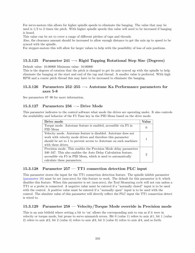
For servo-motors this allows for higher spindle speeds to eliminate the banging. The value that may beused is 1/2 to 2 times the pitch. With higher spindle speeds this value will need to be increased if bangingis heard.This value can be set to cover a range of different pitches of taps and threads.Also, the clearance amount should be increased to allow enough distance to get the axis up to speed to besynced with the spindle.For stepper-motors this will allow for larger values to help with the possibility of loss of axis positions.
15.3.125 Parameter 241 —- Rigid Tapping Rotational Step Size (Degrees)
Default value: 10.00000 Minimum value: 10.00000This is the degrees of rotation that the pitch is changed to get its axis synced up with the spindle to helpeliminate the banging at the start and end of the tap and thread. A smaller value is preferred. With highRPM and a coarse pitch thread this may have to be increased to eliminate the banging.
15.3.126 Parameters 252–255 —- Autotune Ka Performance parameters foraxes 5-8
See parameters 87–90 for more information.
15.3.127 Parameters 256 —- Drive Mode
This parameter indicates to the control software what mode the drives are operating under. It also controlsthe availability and behavior of the F5 Tune key in the PID Menu based on the drive mode.
Drive mode ValueTorque mode. Autotune feature is enabled, accessible via F5 inPID Menu
0
Velocity mode. Autotune feature is disabled. Autotune does notwork with velocity mode drives and therefore this parametershould be set to 1 to prevent access to Autotune on such machineswith these drives.
1
Precision mode. This enables the Precision Mode delay parameters340–347. This also enables the Auto Delay Calculation feature,accessible via F5 in PID Menu, which is used to automaticallycalculate these parameters.
2
15.3.128 Parameter 257 –– TT1 connection detection PLC input
This parameter stores the input for the TT1 connection detection feature. The spindle inhibit parameter(parameter 18) must be set (non-zero) for this feature to work. The default for this parameter is 0, whichdisables this feature. When this parameter is set (non-zero), the Tool Measuring cycle will not run unless aTT1 or a probe is connected. A negative value must be entered if a ”normally closed” input is to be usedwith the control. A positive value must be entered if a ”normally open” input is to be used with thecontrol. The absolute value of this parameter will directly reflect the PLC input the TT1 connection detectis wired to.
15.3.129 Parameter 258 –– Velocity/Torque Mode override in Precision mode
This is an axis bitfield where setting a bit to ‘on’ allows the corresponding axis to run as if it were invelocity or torque mode, but prone to servo mismatch errors. Bit 0 (value 1) refers to axis #1, bit 1 (value2) refers to axis #2, bit 2 (value 4) refers to axis #3, bit 3 (value 8) refers to axis #4, and so forth.
310

15.3.130 Parameter 259 –– Manual Axis Designation
This parameter is a bit field that designates an axis as a manual axis regardless of its label. Bit 0 (value 1)refers to axis #1, bit 1 (value 2) refers to axis #2, bit 2 (value 4) refers to axis #3, bit 3 (value 8) refers toaxis #4, and so forth. (Note that there is another way to designate an axis as a manual axis, which is toset its label to “M” or “@”.)
15.3.131 Parameter 260 –– Accelerated Graphics Backplot
This parameter controls the user interface that is presented when F8 – Graph is pressed. See Chapter 3 formore information about Accelerated Graphics Backplot.
Function ValueUse the original Graphics Backplot -1Use the new Accelerated Graphics Backplot 1
15.3.132 Parameter 261 —- Precision Mode Standoff Tolerance Percentage
Indicates the percentage of the motor encoder counts per revolution for which standoff error must exceedbefore any correction is made. Setting P261 to zero disables standoff error correction. Suggested setting is= 0.01
15.3.133 Parameter 262 —- Precision Mode Standoff Delay Time
Time in seconds that an axis must be continuously at rest (no change in expected position) before acorrection is made. Suggested setting is 0.1
15.3.134 Parameter 270–271 –– XY Skew Correction
These parameters work together to correct XY position skew, which can occur if the X axis is not exactlyperpendicular to the Y axis (or vice versa). To turn on XY skew correction, use the chart and follow theskew measurement procedure described below. To turn off XY skew correction, set both parameters to 0.
Parameter Symbol Description270 S +/- X skew deviation from perfect X and perfect Y
271 LY length over which to apply a position correction to counteract askew of amount S
Skew Measurement Procedure: Program a sufficiently large L x L square and cut it on a scrap piece ofmaterial using the machine in question. Put this “square” piece against a true square corner and measurethe skew S. If the square is leaning to the left, then S is negative; if it is leaning to the right, then S ispositive. Set Parameter 270=S and Parameter 271=L.
311

If you have trouble directly measuring S, you can calculate it by measuring the diagonals D1 and D2, andthen using the following formula: S = (D12 −D22)/(4L)
15.3.135 Parameter 278 —- Spindle Speed Display Precision
This sets the number of digits after the decimal point to display on the Spindle Speed display in the StatusWindow. A setting of 0 means to show whole number spindle speeds.
15.3.136 Parameter 284–291 –– Brake Resistor Wattage for ACDC Drives 1–8
These parameters specify the brake resistor wattage which default to the minimum internal resistor value.If CNC11 detects that the estimated brake wattage exceeds these parameter settings, then a ”470 axis(drive ) brake wattage exceeded” message is reported in the status window. These warnings may bewritten at most twice a minute. User variables #27201-#27208 can be used in an M- or G-code program toreturn the estimated brake wattage as reported by the ACDC drive to MPU11. Note that these are drivenumbers, and match the LED indicator on the ACDC drive, but do not necessarily match the axes asdisplayed in the DRO due to the flexibility of drive mapping.
15.3.137 Parameter 300–307 –– Drive assignment to Axes 1-8
These parameters control to what physical drive the commands for motion are sent. Parameter 300 assignsa physical drive to axis 1, parameter 301 assigns a physical drive to axis 2, and so on. The values for theseparameters can be set to any value from 1-25 based on the table below. These parameters must be setbefore attempting to move motors. Note that if you change any of these values, the machinemust be powered down and restarted for the changes to take effect. Contact your dealerbefore changing these values.
312
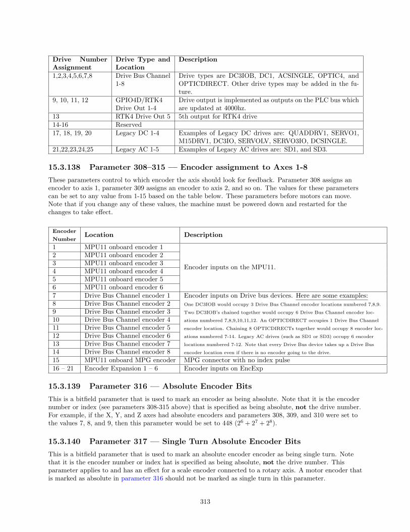
Drive NumberAssignment
Drive Type andLocation
Description
1,2,3,4,5,6,7,8 Drive Bus Channel1-8
Drive types are DC3IOB, DC1, ACSINGLE, OPTIC4, andOPTICDIRECT. Other drive types may be added in the fu-ture.
9, 10, 11, 12 GPIO4D/RTK4Drive Out 1-4
Drive output is implemented as outputs on the PLC bus whichare updated at 4000hz.
13 RTK4 Drive Out 5 5th output for RTK4 drive14-16 Reserved17, 18, 19, 20 Legacy DC 1-4 Examples of Legacy DC drives are: QUADDRV1, SERVO1,
M15DRV1, DC3IO, SERVOLV, SERVO3IO, DCSINGLE.21,22,23,24,25 Legacy AC 1-5 Examples of Legacy AC drives are: SD1, and SD3.
15.3.138 Parameter 308–315 –– Encoder assignment to Axes 1-8
These parameters control to which encoder the axis should look for feedback. Parameter 308 assigns anencoder to axis 1, parameter 309 assigns an encoder to axis 2, and so on. The values for these parameterscan be set to any value from 1-15 based on the table below. These parameters before motors can move.Note that if you change any of these values, the machine must be powered down and restarted for thechanges to take effect.
Encoder
NumberLocation Description
1 MPU11 onboard encoder 1
Encoder inputs on the MPU11.
2 MPU11 onboard encoder 23 MPU11 onboard encoder 34 MPU11 onboard encoder 45 MPU11 onboard encoder 56 MPU11 onboard encoder 67 Drive Bus Channel encoder 1 Encoder inputs on Drive bus devices. Here are some examples:
One DC3IOB would occupy 3 Drive Bus Channel encoder locations numbered 7,8,9.
Two DC3IOB’s chained together would occupy 6 Drive Bus Channel encoder loc-
ations numbered 7,8,9,10,11,12. An OPTICDIRECT occupies 1 Drive Bus Channel
encoder location. Chaining 8 OPTICDIRECTs together would occupy 8 encoder loc-
ations numbered 7-14. Legacy AC drives (such as SD1 or SD3) occupy 6 encoder
locations numbered 7-12. Note that every Drive Bus device takes up a Drive Bus
encoder location even if there is no encoder going to the drive.
8 Drive Bus Channel encoder 29 Drive Bus Channel encoder 310 Drive Bus Channel encoder 411 Drive Bus Channel encoder 512 Drive Bus Channel encoder 613 Drive Bus Channel encoder 714 Drive Bus Channel encoder 815 MPU11 onboard MPG encoder MPG connector with no index pulse16 – 21 Encoder Expansion 1 – 6 Encoder inputs on EncExp
15.3.139 Parameter 316 — Absolute Encoder Bits
This is a bitfield parameter that is used to mark an encoder as being absolute. Note that it is the encodernumber or index (see parameters 308-315 above) that is specified as being absolute, not the drive number.For example, if the X, Y, and Z axes had absolute encoders and parameters 308, 309, and 310 were set tothe values 7, 8, and 9, then this parameter would be set to 448 (26 + 27 + 28).
15.3.140 Parameter 317 — Single Turn Absolute Encoder Bits
This is a bitfield parameter that is used to mark an absolute encoder encoder as being single turn. Notethat it is the encoder number or index hat is specified as being absolute, not the drive number. Thisparameter applies to and has an effect for a scale encoder connected to a rotary axis. A motor encoder thatis marked as absolute in parameter 316 should not be marked as single turn in this parameter.
313

15.3.141 Parameter 318 — Five Axis Configuration
This parameter specifies configuration settings specific to five axis systems. On five axis systems that havethe fifth axis (usually labeled B) as a rotary axis that rotates around a line parallel to the Y axis, i.e., anarticulated head, values 1-8 are used to specify the drive to which the scale encoder is connected. Anon-zero value also signifies that the fifth axis is a ”straight rotary” (it is not a ”triangular rotary” type).
15.3.142 Parameter 323 –– MPU11 Encoder Speed Filter
This is an axis bitfield where setting a bit to ‘on’ selects the low speed filters for the corresponding axis. Asa general guideline, an axis’s bit should be set unless that axis refers to a 3rd party drive. Bit 0 (value 1)refers to axis #1, bit 1 (value 2) refers to axis #2, bit 2 (value 4) refers to axis #3, bit 3 (value 8) refers toaxis #4, and so forth.
15.3.143 Parameter 324–331 –– Axis Boxcar Size
These parameters set the maximum sample size of the boxcar filter for each axis. For most applicationsthese values should be set to 0 (default). For applications where the motor drives are too responsive orjumpy, these boxcar filters act as a way to smooth the PID output. They average the PID output by theentered boxcar size thus reducing PID spikes. Eg. A value of 4 would add the last 4 PID values and thendivide by 4 for before output. A value of 5 would add the last 5 PID values then divide by 5 before output.Note that during PID averaging, the Error Sum is not zeroed during direction reversal. Conversely, a valueof 0 disables the boxcar filter for that axis and also zeroes the Error Sum on Direction Reversal. Note alsothat as a byproduct of averaging by 1, a boxcar value of 1 may be used to produce a true PID output whilenot zeroing the Error Sum on direction reversal.
15.3.144 Parameters 332–335 –– Encoder error suppression
These parameters control suppression of various types of encoder errors on a per encoder basis. Theseparameters are bitfields by encoder index, NOT axis index. The mpu11 has 15 encoder indexes. Forexample to disable encoder faults for Encoder #5 on the mpu11, enter a 16 into the parameters 332 and334. To suppress encoder faults and error messages for all 8 axes, enter 255 into each of the paramtersmentioned in the following table.
Parameter Function332 Suppress encoder differential faults333 Suppress encoder differential error messages334 Suppress encoder quadrature faults335 Suppress encoder quadrature error messages
15.3.145 Parameters 336–339 –– Motor torque estimation for velocity modedrives
These parameters are intended to be used with velocity mode drives in order to faciliatate a more accuratedisplay of the axis load meter bars shown under each position in the main DRO display. If P336 = 0, thenthis feature is disabled and the normal PID output is displayed by the axis load meter bars. This feature isenabled if P336 is non-zero.
Parameter Symbol Function336 G Overall gain setting (0 = disable Motor torque estimation)337 Ga Absolute error gain338 Gs Error sum gain339 Gd Delta error gain
314

Technical details:The axis meter bar value (V) is then calculated as: V = abs(100.0*G*((Ea*Ga + Es*Gs +
Ed*Gd))/integration limit), where Ea is the absolute error, Es is the error sum, and Ed is the deltaerror from the PID algorithm and the integration limit is from the ”Limit” value set in the PID Configscreen . This value V is then bound to the range 0–100.
15.3.146 Parameters 340–347 –– Precision Mode delay (in milliseconds) foraxes 1-8
These parameters are used for synchronizing individual precision mode drives with different delays. TheMPU11 will use these values and compensate for the differences in the delays. These parameters have upto a 0.25 millisecond resolution.
15.3.147 Parameter 348, 351, and 354 –– MPG/Handwheel Encoder Input 1,2, and 3
The encoder input for the MPG or handwheel. (1-15) See the encoder chart above. Note: PLC programinteraction is needed to enable an MPG or handwheel.
15.3.148 Parameter 349, 352, and 355 —- MPG/Handwheel Detents perRevolution 1, 2, and 3
This value is the number of clicks (detents) per revolution. It is the number of divisions or markings on thempg or handwheel. Moving the mpg or handwheel one detent or division will cause the motor to move onejog increment (depending on the multiplier x1, x10, x100, etc). . Note: PLC program interaction is neededto enable an MPG or handwheel.
15.3.149 Parameter 350, 353, and 356 –– MPG/Handwheel Encoder Countsper Revolution 1, 2, and 3
This value is the number of counts generated per rotation of the mpg or handwheel. Note: PLC programinteraction is needed to enable an MPG or handwheel.
15.3.150 Parameters 357–364 –– Axis Drive Max RPM for Axes 1-8
These parameters allow you to set the drive/motor max rate capability (in RPMs) for use by the PIDalgorithm for the calculation of the axis KV1 contribution. This value is independent from the axis MaxRate setting in the Jog Parameters menu, which is used by the control software. However, for those axeswhose corresponding parameters are set to 0 (the default) the the PID algorithm will use the axis MaxRate setting in the Jog Parameters for the calculation of the axis KV1 contribution. These parameters areintended for 3rd party velocity mode drives that have a different max rate setting than that of the controlsoftware.
15.3.151 Parameters 365 –– Drive power-on delay
This specifies the number of milliseconds that the MPU11 will wait between the moment that drive powerfirst comes on and the start of commanded motion. However, this does not work for the case of turning offa single axis using M93, moving a different axis, and then moving the powered off axis. The default value is0 which means no delay.
315
15.3.152 Parameters 366 – 367 –– Probe / TT1 deceleration multiplier
Parameter Function
366Probe deceleration multiplier:This factor adjusts the deceleration rate of probing moves coming to a stop dueto probe hit.
367TT1 deceleration multiplier:This factor adjusts the deceleration rate of TT1 tool measuring moves coming toa stop due to tool touch detect.
The normal axis acceleration rate (configured by dividing the Max Rate in the Jog Parameters screen bythe Accel Time in the PID Config screen) is multiplied by the value of these parameters to determine theactual decelerations used for each situation. A value higher than 1 will cause a more abrupt decelerationthan the normal axis configuration. A value below 1 will cause a gentler deceleration.
15.3.153 Parameter 368 — Autonomous Digitizing Angle Adjustment
This parameter determines by what angle adjustments will be made to avoid shanking during AutonomousDigitizing. Note: This parameter applies only to performance racing users.
15.3.154 Parameter 369 — Tool Check Max Absolute Angle
This parameter is used in five-axis systems that have articulated heads (a rotary axis usually labeled as B)to limit the angle at which the tool check can be performed. If the absolute value of the B axis exceeds thisvalue, a warning is displayed. This parameter also specifies a limit for the tilt angle used in five axisautonomous digitizing routines.
15.3.155 Parameters 374–379 –– ACDC Drive Debug Log Settings
These parameters are used by support technicians and should be left at value 0.
15.3.156 Parameters 392–394 –– DP-7 parameters
These are parameters specific to the DP-7 probe and are used only if parameter 155 = 2.
Parameter Function
392DP-7 Pullback Distance:The distance the probe moves off of the surface after a probing move.
393DP-7 Pullback Feedrate:The feedrate for the pullback move.
394DP-7 Measuring Feedrate:The feedrate for the slow measuring move.
15.3.157 Parameters 395 –– Probing Setup Traverse Speed
This sets the probing traverse feedrate for the macro-based probing cycles on engine block systems.
15.3.158 Parameters 396 –– Probing Setup Plunge Speed
This sets the probing plunge feedrate for the macro-based probing cycles on engine block systems.
15.3.159 Parameters 398 –– Port/Block mode
This determines the current mode of Port/Block systems and is set by the Port/Block menu. Thisparameter should not be manually modified.
316

Value Mode0 3-Axis1 Engine Block2 Tilt Table
15.3.160 Parameters 399 –– AD1 arc chord tolerance adjustment
This parameter adjusts the precision of AD1 arcs. When Smoothing is turned off (P220 = 0) arc moves(such as G2 and G3) are generated as a string of many small linear moves that are used to closelyapproximate the programmed arc. These small linear moves are called arc chords. These arc chordsstraddle each side of the theoretical true arc path, but their distance (in encoder counts) from the path islimited by what value is set in this parameter. The default value is . 5, meaning that by default the arcchord never strays away from theoretical true arc by more than 1/2 encoder count.
15.3.161 Parameter 400 — Run Menu Cycle Start Enabled
Set this value to zero to disable the CYCLE START button in the Run Menu (F4 from Main Menu). Forany other value, CYCLE START will be enabled on the Run Menu.
15.3.162 Parameter 401 — Forget last job loaded
Setting this parameter to a value of 1.0 will cause the last job loaded to be forgotten when CNC software isstarted and replaced with the name ”no job loaded.cnc”.
15.3.163 Parameter 403 — Disable Keyboard Jogging Legend
This parameter determines whether or not the Keyboard Jogging Legend is launched with an Alt+j press.A value of 1.0 will prevent it from launching.
15.3.164 Parameter 411 — MPG Type
Set this parameter to select the type of MPG connected according to the table below.
MPG type ValueNon-USB MPG 0USB CWP-4 0USB WMPG-4 1
15.3.165 Parameters 900–999 —- PLC program parameters
These parameters are used as a way of communicating floating point values to a PLC program. Themeanings of these parameters depends on how a PLC program uses them and can vary from one machineto another. One suggested use of these parameters is as a set of configuration values. The values of theseparameters are saved upon modification (via a menu or CNC job) and will be retain their values even aftershutdown and restart of the control software.
All remaining parameters are reserved for further expansion.
15.4 PID Menu
Pressing F4 - PID from the Configuration screen will bring up the PID Menu. The PID Menu providesqualified technicians with a method of changing the PID dependent data to test and configure yourmachine.
317

The PID Parameters should not be changed without contacting yourdealer. Corrupt or incorrect values could cause damage to the machine,personal injury, or both.
15.4.1 F1 — PID Config
This option displays the Oscilloscope tuning screen, and is intended for qualified technicians only. Itallows technicians to modify the PID values, and to see (in real time) the effects of those modifications.Altering the PID values will cause DRAMATIC changes in the way the servo system operates, leading topossible machine damage. DO NOT attempt to change these parameters without contacting your dealer.
The general idea is to reduce the Absolute Error (ErrAbs) and the Sum of Absolute Error (ErrSum), whichare both measured in encoder counts. Absolute Error tells you how far off position the machine is at anyparticular point in time, and the Sum is used when tuning to make sure the overall error is being reduced.
Special Note for SD3 drives: The program containing test moves (edited via F1 and run via F2 on theOscilloscope tuning screen) must contain a dwell (G4 P ), otherwise the SD3’s drive parameters will notbe sent.
318

F1 –– Edit Program Change the program that will run when F2 is pressed
F2 –– Run Program Causes the machine to run a simple test program, while collecting data
F3 –– Ranges Can be used to specify the X and Y ranges for the Oscilloscope view
F4 –– Toggles & Pan Allows changes to how the collected data is displayed, and panning via the cursorkeys
F5 –– Zoom In Zooms in
F6 –– Zoom Out Zooms out
F7 –– Zoom All Fits all of the collected data into the Oscilloscope view
F8 –– Change Axis Tells the MPU11 to collect data for a different axis (displayed in the top left)
F9 — Save & Apply Saves any modifications
F10 –– Save & Exit Saves any modifications and exits the Oscilloscope menu
Page Up –– Tweak + Allows small modifications (+1to the PID values while the program is running.Hold shift for a larger (+10%) modification.
Page Down –– Tweak - Allows small modifications (-1to the PID values while the program is running.Hold shift for a larger (-10%) modification.
Improper PID values can ruin the machine, cause personal injury, and/ordestroy the motor drives!!!
319
15.4.2 F5 - Tune
This option is available only for Torque mode and Precision mode drives. See Parameter 256 earlier in thischapter for more information about Drive modes.
If the drives are in Torque mode, pressing this key will start the Autotune procedure. It is used byqualified technicians to automatically determine values for Max Rate, Accel/decel time, and Deadstart (Seesection Motor Configuration: Jog Parameters) as well as certain PID parameters for each installed axis.The Autotune procedure will make a series of moves on each non-paired controlled axis, traveling a limiteddistance (configured via parameters 95-98 and 156- 159) from the initial position in all directions todetermine the friction and gravity of each axis. The initial high-speed move will use half of this distance.You cannot run Autotune on paired axes. Do not run Autotune unless requested to do so by a qualifiedtechnician.
If the drives are in Precision mode, pressing this key will start the Auto Delay Calculation procedure. It isused by qualified technicians to automatically determine values for the Precision Mode delay parameters340-347. The Auto Delay Calculation procedure will make a single move on each non-paired controlledaxis, traveling a limited distance (configured via parameters 95-98 and 156-159) from the initial position.You cannot run the Auto Delay Calculation procedure on paired axes. Do not run the Auto DelayCalculation procedure unless requested to do so by a qualified technician.
15.4.3 F6 — Drag
This option is used by qualified technicians to determine whether your machine is binding anywhere alongthe axis travel. To run a drag test press F6 — Drag to begin the drag test. Press F1 — Next Axis to selectthe axis you wish to check and then hit the CYCLE START button. A text file drag x.out, or a similarlynamed file is generated and stored in the c:\cncm directory. If significant drag occurs, a message will bedisplayed on screen. Contact your dealer to correct the problem as soon as possible.
15.4.4 F7 — Laser
This option is used by qualified technicians to take automated laser measurements and create or adjust theballscrew compensation tables. Do not attempt to run automatic laser compensation without firstcontacting your dealer for details.
15.4.5 F8 — Drive
This menu will only appear on AC systems and only affects using SD or ACSingle drives. It is not forgeneral viewing and definitely not for modification by any unqualified individual. For more informationabout this menu option, refer to the SD installation manual.
15.4.6 F9 — Plot
This option is used by qualified technicians to plot data.
15.5 System Test
System Test is a feature that was released in software versions 8.23 (DOS) and 1.10 (CNC10). The purposeof the System Test is to check basic machine functionality and to verify key parameters are set correctly. Ifthe System Test has not run and passed, a message will be displayed on the screen at power up (see figure).This message will continue to be displayed at power up, until the System Test has been run successfully.
320

Requirements before running System Test:
1. Make sure control is fully integrated.
2. Check direction of each axis and change direction reversal (refer to TB137) and limits as required.
3. Setup/calibrate motor rev.’s/per (refer to TB36) and backlash (refer to TB37) for each axis.
4. Set travel limits. (Note: To save time in the home switch test, zero out the inputs that aren’t beingused for home switches.)
5. Run auto tune and drag tests.
6. Make sure machine table is cleared of all items.
7. Empty the spindle of any tools, and verify that the spindle face cannot run into the worktable at thebottom of its travel. DO NOT START the system test with a tool in the spindle.
8. (ATC systems only) ATC systems need to have their tool changers setup and verified by running toolchanges.
9. (ATC systems only) Insert at least four tools into the tool carousel. Load one into bin #1 andanother into the maximum bin number (ex. Load into bin 16 if a 16 - Tool ATC). The other twotools should be loaded into the carousel to balance it out. In the case of a 16 - Tool ATC load bins 5and 10. The tools must have lengths that differ by at least 0.010 inches (0.25 mm). Do NOT use flycutters, diamond tip tools or non conductive tools.
10. (ATC systems only) Position a TT1 on the worktable and connect the TT1 cable. Position thespindle over the TT1 then press F1 – Setup, F1 – Part, F9 – WCS Table and F1 – Return. Enter theX and Y values displayed on the screen in return point #3 and set the Z value to zero. Note; make
321

sure the spindle face will not run into the TT1 at the bottom of its travel (if it doesn’t clear, do NOTrun the System Test).
Running the System Test:
1. To run the System Test, press F1 – Setup, F3 – Config, enter the correct password, and then pressF5 – Test. The control will load the systest.cnc file located in the CNC10 directory. If for anyreason the systest.cnc file does not load, go to the CNC10 directory and manually load it.
2. Before System Test starts running any tests it moves the Z-axis to home. The travel limits andmachine home are verified that they are set. Travel limits are not tested for axes that are labeled asM, N, or S, or that have the rotary bit set in parameters 91-94 (axes 1-4) and or 166 (5th axis). Thetest also checks parameter 6 and 160, if P6 is set to 1 and 160 is set to a non-zero value the SystemTest will display a menu where you can select a single test or run all tests.
3. Here is a quick list of the Tests; below you can read about them in more detail.
(a) ATC — TT1 Test
(b) Quick Home Switch Test
(c) ATC — Spindle Test
(d) ATC — Tapping Test
(e) Home Switch and Travel Limit Test
(f) ATC — Tool Change Test
Note that Non-ATC systems will automatically run tests (b) and (e).
If System test fails at any time while testing you will see “Missing parameter, line 989” on the ConfigScreen. Go back to the main screen where you will see the following screen (see figure below). Load thesystest.out file located in the CNC10 directory and press F6 –– Edit to see exactly what failed (See figure).
322

Test Definitions:
1. ATC TT1 Test. This test starts with the following G-code message displayed on the screen:
; * Connect TT -1 and verify the XY location of the TT -1
; * is set in return point #3. Verify that the spindle\
; * face is above the TT -1 when at the Z minus travel
; * limit. After pressing CYCLE START ,
; * trigger the TT -1 twice.
M0
if [#9044 != 0] the #[a] = #9044
if [#9044 == 0] the #[a] = #9011
M123 L1 ; TT -1 set to be input
M123 q0 p#a
M101/#a
After pressing Cycle Start, the TT1 needs to be manually triggered twice. The best way to do this isby touching an electrically conductive material to the worktable and the top of the TT1. Aright-angled Allen-wrench about six inched long works well.
323

Before triggering the TT1 you will notice in the message window the message “Waiting for input #15(M101)”. If the TT1 parameters are set correctly the program will stop at a M0 after triggering theTT1. If the program doesn’t reach the second M0 shortly after triggering the TT1, stop the program.Press Alt + I to turn on Live PLC debugging and trigger the TT1 to see which input is actuallytoggling and then change parameter 44 to the input being tripped. If no input is tripped check theTT1 wiring.
2. Home Switch Test This test checks to see if the machine can be homed reliably by making sure thehome switches are not too close to the index pulse of the motors. If this test fails and you get a“home switch too close to index pulse” error message, refer to Tech bulletin 92 for a description ofhow to correct the problem.
3. ATC Spindle Test This test is made up of three parts:
(a) First parameter 78 (Spindle Speed Display) is set to 1.0 to enable live measurement andcalculated spindle speed to be displayed in the CNC status window. Parameter 36 (RigidTapping Enable/Disable) is set to 1.0 to enable rigid tapping and parameter 33 (Spindle MotorGear Ratio) is checked to see if it’s set to 1.0. If not set to 1.0, it will be changed to a 1.0 and awarning will be logged.
(b) The program turns the spindle on for a few seconds and looks for any change in the absoluteencoder position of all axes. If no changes are detected, the test will error out and log thefailure. In which case the spindle encoder wiring and connections need to be checked. Ifmovement is detected, parameter 35 is verified that it’s set correctly. A wrong value will resultin a failure; the failure message in the systest.out file will indicate the correct value. Change P35and run test again. A quick check for spindle direction is made, where the spindle is turned onwith an M3 to see in the spindle is counting up or counting down. If counting up nothinghappens, counting down will result in a minus sign being added or removed from parameter 34(Spindle Encoder Counts/Revolution) and a warning logged.
(c) The test now records the average spindle deceleration time from 2000RPM. Then spindle speedsof 10%, 20%, 30%, ..., up to 100% of maximum spindle speed set in the Control Configurationare checked and recorded in systest.out. The spindle speeds are commanded and then the actualspeeds are recorded after several seconds. The commanded speeds are compared to theactualand must be within 3% to pass. If a failure occurs check P34 is set correctly and that theinverter has been programmed for the correct maximum output frequency. To check parameter
324

34 turn the spindle 10 times by hand and divide the difference in encoder counts by 10. Theabsolute encoder position can be read off the PID screen.
4. ATC Tapping Test. Starts at machine home and taps down three inches at 1000RPM. The Z-axismovement should be very smooth, however if you notice a jerky motion it is probably due to P34having the wrong sign (+/-). For example, if P34 is set to 4096 and you have jerky motion on Z-axischange P34 to –4096. Another problem could occur with a “Z axis cannot follow the spindle” error.This means you have the wrong number of counts in P34 (i.e.8000 instead of 4096), although thecorrect value for P34 should have been determined in spindle test.
5. Machine Home Switch and Travel Limit Test.
(a) Home Switch test. The machine home test starts by checking the values stored in theplus/minus home switch fields in the Machine Configuration –– Motor screen. There are twochecks made before the test begins. The program first checks the “Machine home at pwrup”setting in the Control Configuration. If set to “Jog” the test is skipped and a warning is loggedin systest.out. In most cases it should be set to “Home switch” or “Ref Marks — HS”. Thesecond check looks for any axis that has at least one home switch input defined except for,rotary configured axes or axes with an “M”, “N”, or “S” label. Reference Mark homing willhave both plus/minus home switches set to zero. So any axes that fail this check will generate awarning in the systest.out file.
Review of homing process when homing to a switch:
i. The axis moves toward the home switch at the slow jog rate until the home switch is tripped.
ii. The axis moves away from the switch until the home switch closes.
iii. The axis moves further away by a small amount (0.0025 inches).
iv. The axis moves in small increments away from the switch until the encoder index pulse islocated.
Axes with a minus home switch defined will have multiple measurements taken of the homeposition (found by using an M91/ command) and the position after step (3) in the homingprocedure. The measurements are logged along with error measurements and other data. Topass the test, all home position measurements must be within 0.0005 inches of the firstmeasurement. If the test fails and the error is within 0.0010 inches of a motor revolution, thefollow message will be logged: “SUSPECTED LIMIT SWITCH PROBLEM”. Otherwise,“SUSPECTED ENCODER INDEX PROBLEM” will be logged.
Now the distance between the home position and the off-switch position (position after step 3)are checked to ensure that they are not less than 1/8 or greater than 7/8 of a motor revolution.If less than 1/8 or greater than 7/8 of a motor revolution a failure occurs and a “Home positiontoo close to encoder index pulse” message is logged (See figure 4). To correct this failure, movethe limit switch or trip dog a distance that corresponds to a 1/2 revolution of the motor. Thefull turn distance is recorded in the systest.out file. If unable to move, decouple the motor androtate the motor shaft 90 degrees clockwise. When attempting to resolve the problem byrotating the motor shaft, note that this method will affect the results of the home switch test atthe other end of travel, which means that it is possible when the test is repeated that theopposite end which passed will now fail. In this case, you must rotate the motor shaft 90 degreesclockwise once again.
325
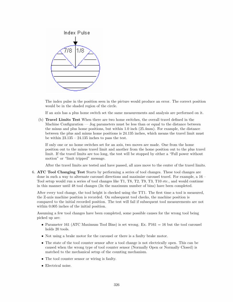
The index pulse in the position seen in the picture would produce an error. The correct positionwould be in the shaded region of the circle.
If an axis has a plus home switch set the same measurements and analysis are performed on it.
(b) Travel Limits Test When there are two home switches, the overall travel defined in theMachine Configuration –– Jog parameters must be less than or equal to the distance betweenthe minus and plus home positions, but within 1.0 inch (25.4mm). For example, the distancebetween the plus and minus home positions is 24.135 inches, which means the travel limit mustbe within 23.135 – 24.135 inches to pass the test.
If only one or no home switches set for an axis, two moves are made. One from the homeposition out to the minus travel limit and another from the home position out to the plus travellimit. If the travel limits are too long, the test will be stopped by either a “Full power withoutmotion” or “limit tripped” message.
After the travel limits are tested and have passed, all axes move to the center of the travel limits.
6. ATC Tool Changing Test Starts by performing a series of tool changes. These tool changes aredone in such a way to alternate carousel directions and maximize carousel travel. For example, a 16 –Tool setup would run a series of tool changes like T1, T8, T2, T9, T3, T10 etc., and would continuein this manner until 48 tool changes (3x the maximum number of bins) have been completed.
After every tool change, the tool height is checked using the TT1. The first time a tool is measured,the Z-axis machine position is recorded. On subsequent tool checks, the machine position iscompared to the initial recorded position. The test will fail if subsequent tool measurements are notwithin 0.005 inches of the initial position.
Assuming a few tool changes have been completed, some possible causes for the wrong tool beingpicked up are:
• Parameter 161 (ATC Maximum Tool Bins) is set wrong. Ex. P161 = 16 but the tool carouselholds 20 tools.
• Not using a brake motor for the carousel or there is a faulty brake motor.
• The state of the tool counter sensor after a tool change is not electrically open. This can becaused when the wrong type of tool counter sensor (Normally Open or Normally Closed) ismatched to the mechanical setup of the counting mechanism.
• The tool counter sensor or wiring is faulty.
• Electrical noise.
326

Completed System Test If the control runs through the complete test and passes everything thesystest.out file will say passed and the “Machine setup not completed” message will no longer appear atmachine power up.
WARNING: If you run the system test after it’s already passed, the systest.out file will be wiped out andthe control will need to run through the complete test again.
15.6 ATC Init.
This menu will only appear on enhanced ATC systems. Please see your ATC manual for furtherinformation.
15.7 DSP Probe Configuration
Pressing F7 —- DSP Probe from the configuration screen will display the DSP Probe configuration. Notethat this menu is available only for DSP probes (Parameter 155=1).
Minimum Difference:Default - 0.001 inches. The minimum difference between mechanical and reported DSP position.
Maximum difference:Default - 0.025 inches. The maximum difference between mechanical and reported DSP position.
DSP Probing feedrate:Default – 20. The feedrate to use for DSP probing moves.
DSP Probing Clearance feedrate:Default – 20. The feedrate to use for DSP probing Clearance moves.
327

DSP Retry Limit:Default - 10 times. The maximum number of tries to achieve a passing window.
Force DSP probing feedrate in M115/M116:Default - Yes. This forces the DSP feedrate for M115/M116 (recommended) rather than using the feedratespecified in an F command.
Accept Mechanical Points in Digitizing CyclesDefault –Yes. Used when any given point has failed window checking # times where # = the limit asspecified in DSP Retry Limit. Setting this option to Yes records the last mechanical position rather thanthrow out the point entirely. If this option is set to no, no value is recorded for the point and digitizingcontinues.
DSP Retry Dwell TimeDefault – 0 seconds. The amount of time to dwell at the end of a retract move when retrying a DSPprobing move. The purpose of this is to give the probe time to stop vibrating before moving towards thesurface again on a bad hit.
Other DSP Probe settingsThe DSP Probe eliminates the need for a multiple-hit probe measuring move (A fast inward move to findthe surface followed by a slow move to measure the surface). Therefore, the Slow Probing Rate (parameter15) does not apply to probing moves when the DSP probe is enabled. However, the Slow Probing Rate stillapplies to TT1 tool measurements. The Fast Probing Rate (parameter 14) is still used for positioningmoves in digitizing cycles, but not for probing mvoes which measure the surface. Instead, the DSP Probingfeedrate is used for these moves.
The following list is a list of other parameters which affect the DSP Probe. See the parameter descriptionsin the Machine Parameters section (earlier in this chapter) for more information.
• Probe Type (Parameter 155): This parameter enables/disables the DSP Probe.
• Recovery Distance (Parameter 13): This parameter is used for failed DSP windows. On a failedwindow, the DSP probe will retract this distance before retrying.
• Fast Probing Rate (Parameter 14): Used for positioning moves in digitizing and probing routines.These are moves which are not measuring a surface. It is not used for surface measuring moves whenthe DSP probe is enabled.
• Slow Probing Rate (Parameter 15): Not used by the DSP probe. However, it will still be used byTT-1 tool measurements.
• Repeatability Tolerance (Parameter 151): Recommended value is 0 (disabled). This parameterenables repeatability checking. It will work in conjunction with the DSP probe.
15.8 Smoothing Configuration Parameters
Parameter Description Recommended values
220 Turn the Smoothing feature ON or OFF.1 = Smoothing (set to 0 to use ExactStop mode)
221 NBpts: The number of points in the Smooth-ing filter. The higher this value, the morerounded corners will become (see tolerance be-low)
For MillingMachines:0 to 10
For Routers:5 to 20
328

222 STEP: Smoothing breaks up a G codeprogram into segments of this vector size.Use this rule of thumb: Tolerance =(Nbpts*STEP)/3.
For MillingMachines:.001 inch / .025mm
For Routers:.01 inch / .25mm
223 Umax: Sustained safe throughput rate goingto the CPU10/MPU11 card.
800
224 Centripetal control options: This bitfieldparameter controls the Centripetal stage ofthe Smoothing module. Value 0 (default)makes Centripetal operate on all axes and dis-ables excessive axis accel checking. Values 1and 3 (bit 0 = 1) limits Centripetal to onlylinear axes. Values 2 and 3 (bit 1 = 1) enablesexcessive axis accel checking
0 ( Centripetal stage will operateon all axes and disables excessiveaxis accel checking.)
226 W: Feature Width over which the Min Angleis determined.
10
227 Min Angle: Minimum angle to smooth indegrees. Settings of 95 to 100 degrees willcome to a near stop and produce sharp rightangles. 60 to 85 will move continuously whilerounding angles.
For Sharpcorners95 to 100degrees
For roundedcorners 60 to 85degrees
228 S curve: The recommended setting for thisparameter is 0.
0 = Off completely (recommendedsetting)
229 Backplot/Smoothing mode : Smoothingmay slow down the display of Backplot Graph-ics. This parameter allows a faster backplot bynot showing Smoothing.
0 = Faster Backplot, smoothingmay be active but is not shown1 = Slower Backplot, smoothingeffects shown.
230 Curve Feedrate Multiplier: Reducing thisvalue below 1.0 will cause the machine to moveslower around curves and corners, minimizing”bangs” and overshoots. Increasing this valueabove 1.0 may allow you to run your machinefaster if the feedrates in arcs and corners arestill satisfactory.
1.0 (default value)0.1 to 5.0 (Depending on user’spreference for speed vs ”bangs”and overshoots)
231 Acceleration Multiplier: This parameterallows you to adjust the overall acceleration /deceleration rate as a means to reduce machinevibration, and noise during starting, stoppingand feedrate changes. Reducing this value be-low 1.0 will cause more gentle accelerationsand decelerations. Increasing this value above1.0 will cause faster accelerations / decelera-tions.
1.0 (default value)0.5 to 1.5 (Depending on user’spreference for quickness ofaccelerations / decelerations)
329

Note: STEP must be in the same units that the control is currently set to (Inches or MM). Once enteredin, if you change units in the control from inches to mm or vice versa the Smoothing parameters willautomatically be converted to the other units for you, so you don’t have to re-enter them once you’ve typethem in properly.
Technical Background description of Smoothing :Smoothing performs several related functions:
1. Smoothing NBPTS (P221) and STEP (P222)These parameters control geometrical smoothing of the user supplied G-code. Smoothing allowssignificantly higher feedrates to be achieved while reducing vibration, bumps and bangs at corners andangles. It is also great for smoothing over a CAD-CAM generated data with peculiar features. See Fig 1.Smoothing’s strength is also a potential disadvantage, it modifies geometry and rounds corners. See Fig 2.When would you want to use smoothing? The user may want to run smoothly through rectangular Zmovements created by ”breakout tabs” on a router job. Smoothing will allow the job to run at high speedright through the breakout tabs, if the min angle P227 is set to less than 90 degrees.
330

2. P230 Curve Feedrate multiplier Arcs and CornersLow values produce lower feedrates in curves.
3. P231 Acceleration Multiplier
4. Min Angle (P227) defines the minimum angle to apply Smoothing to. All angles below the minimumangle will be sharp. For example if Min Angle is set to 95deg then all angles less than 95 right angle(including 90deg) corners will be sharp (not smoothed).
331

5. Feature width W (P226)W and Min Angle work together to determine which angles will be ”sharp” (not be smoothed). Forexample a Gcode file may contain small spikes, double backs or zig zags of less 1mm that may be causingunwanted slowdowns in an otherwise high speed stretch of toolpath. Given a STEP (P222) = .25mm ,setting W (P226)= 4 (4*.25=1mm) should reduce or eliminate decelerations across the problem toolpath.W does not itself smooth the offending data, that’s the job of Smoothing (controlled by NBpts and STEP),but W does allow you to minimize slowdowns caused by small features, which is very helpful for runningsmooth thru jagged CAD CAM generated G code.
15.9 Smoothing Setup Menu
Pressing F8 –– Smoothing Setup from the Setup menu will bring up the Smoothing Setup Menu. TheSmoothing Setup Menu provides a simplified way of choosing parameters for the Smoothing module.Smoothing is especially useful in controlling and minimizing the amount of banging a machine experiencesas it proceeds along the toolpath. Smoothing is also able to (optionally) round part geometry, allowing forfaster feedrates around corners.
332

F1 will turn off Smoothing. The other quick setup keys F2-F8 (if displayed) will turn on Smoothing andactivate a smoothing preset profile by setting Parameter 220 to 1 and copying preset values from theselected preset into parameters 221-231.
By default the following 4 presets are provided:F2 -— Precision Mill chooses Smoothing with settings for high precision work on a Mill.F3 -– Contouring Mill chooses Smoothing with settings for a Mill, with looser tolerances for roundedgeometry.F4 -— Precision Router chooses Smoothing with settings for precision work on a Router.F5 —- Contouring Router chooses Smoothing with settings for a Router, with looser tolerances forsmooth geometry.
Presets can be modified, added, or removed by pressing F9 – Customize Presets which will give you accessto the menu described in the next section.
15.10 Custom Smoothing Presets Menu
Pressing F9 –– Customize Presets from the Smoothing Setup menu will bring up the screen that allowsyou to customize the Quick Setups keys that appear in the Smoothing Setup menu.
333

There are a total of 99 Smoothing presets. Each Smoothing preset consists of a customizable label and acustomizable set of parameter values that will be copied to the actual parameters P221 through P231(excluding P229) when such a preset is selected in the Smoothing Setup Menu or when activated by the“G64 ON” command.
Smoothing presets #1 through #7 are the only presets that can appear in the Smoothing Setup menu andcorresponds to F2 through F8 in that menu. For these presets (#1 through #7), only those that have anon-blank F-key Label will be appear and be available in the Smoothing Setup Menu. To remove aparticular preset from the Smoothing Setup Menu (presets #1 through #7) , simply delete its Label andleave it blank.
All Smoothing presets can be activated by “G64 ON” in a CNC program or by MDI. Presets activated thisway will still be in effect even after the CNC program is finished. Here are some G64 examples:
G64 ON P1 ;Activate Preset #1 by number
G64 ON "precision mill" ;Activate Preset #1 by label
G64 ON P2 ;Activate Preset #2 by number
G64 ON "contouring mill" ;Activate Preset #2 by label
The ”G64 ON” command with a ”P” number can be used to activate those presets that do not have aLabel. For more details on G64 see Chapter 12.
The Smoothing Presets should not be changed without consulting yourdealer. Corrupt or incorrect values could cause damage to the machine,personal injury, or both.
334

Chapter 16
CNC Software Messages
16.1 CNC Software Startup Errors and Messages
Error Message Cause & Effect Action
102Error initializingCPU...cannot con-tinue.
Error sending a hex file program to the mo-tion control card.
Inspect MPU11 con-nection, or fix missingor corrupted hex file.Contact Dealer
103 Error sending setupError sending the current setup parametersto the motion control card.
Inspect MPU11 con-nection, or fix missingor corrupted hex file.Contact Dealer
104Error sending PIDsetup
Error sending the current PID setup param-eters to the motion control card.
Inspect MPU11 con-nection, or fix missingor corrupted hex file.Contact Dealer
105mpu.plc file read er-ror..cannot continue
Error sending the current PLC program tothe motion control card.
Install or recompilePLC program. Con-tact dealer
106The PC clock appearsto be wrong
Error while reading the temperature file.The time on the PC internal clock is ear-lier than the time recorded in a previouslystored file
199 CNC started CNC control software has started.
16.2 Messages Issued Upon Exit From CNC Software
Error Message Cause & Effect Action
201Exiting CNC dueto a known error(ACORN only)
MPU11 not responding, or mpu11.hex,mpu.plc is missing or damaged.
Check for possiblesoftware corruption.Contact dealer
202Exiting CNC due to amath error
A floating-point math error occurred. Pos-sible corruption of cnc.tem, cncm.job, orcncm.wcs.
Delete corrupted filesand reboot software.Contact dealer
335

Error Message Cause & Effect Action
204ExitingCNC...Normal Exit
CNC control software is shuting down nor-mally.
222 Autotune run Autotune has been run.
16.3 Messages and Prompts in the Operator Status WindowStatus Messages
Error Message Cause & Effect Action
301 StoppedA job has ended normally or the operatorhas aborted the job.
302 Moving...Motors are moving while a CNC programis running.
303 Paused...Motion is paused while a CNC program isrunning (FEED HOLD)
304 MDI... CNC software running in MDI mode
305 Processing...CNC software running in a mode other thanMDI
306 Job Finished. Normal end of CNC program
307Operator abort: jobcanceled
ESC or CYCLE CANCEL pressed. Job iscancelled.
308Waiting for input#NN
M100 or M101 executing. Program willcontinue once specified input opens orcloses.
309Waiting for CYCLESTART button
M0, M1, M100/75, or Block Mode is exe-cuted.
Press Cycle Start
310Waiting for output#NN
M100 or M101 executing. Program willcontinue once specified output opens orcloses.
311Waiting for memory#NN
M100 or M101 executing. Program willcontinue once specified memory bit changesto the correct state.
312Waiting for PLC op-eration (Mnn)
PLC program not clearing PLC operationin progress
313Waiting for dwelltime
G4 executing. Program waits for specifieddwell time then continues.
314Waiting for system#NN
M100 or M101 executing. Program willcontinue once specified PLC system vari-able changes to the correct state.
315 Searching... Run/search in progress
317Waiting for auto-matic tool change
mfunc6.mac executing
318Operator Abort prob-ing cancelled
ESC or CYCLE CANCEL pressed while do-ing a probing move
319Probing cycle can-celled
probing cycle was cancelled
320 Probe stuckprobe is stuck, or probe hit an object whenit wasn’t expecting contact.
336

Error Message Cause & Effect Action
322Stall: probing can-celled
probing was cancelled because of a stall
323 Stall: job cancelled job was cancelled because of a stall
324Limit: probing can-celled
probing was cancelled because of a limit er-ror
325 Limit: job cancelled job was cancelled because of a limit error
326Fault: probing can-celled
probing was cancelled because of a fault
327 Fault: job cancelled job was cancelled because of a fault
328Cutter comp error:job cancelled
job was cancelled because of a cutter comperror
329Invalid parameter:job cancelled
job was cancelled because of an invalid pa-rameter
330Canned cycle error:job cancelled
job was cancelled because of a canned cycleerror
332 Search FailedRun/Search was unable to find the re-quested G-code line
334Locating position toresume job...
Run/Search is locating the job continuationpoint in the program
335Emergency Stop Re-leased
Emergency Stop Button has been released
336 Digitize cancelledESC or CYCLE CANCEL pressed duringdigitizing
337 Digitize complete A digitizing routine ran to completion
338 Job CancelledESC or CYCLE CANCEL pressed duringjob run
339 Jogging...An axis jog key is pressed and machine ismoving the corresponding axis
340 Limit (# ) clearedA previously tripped limit switch is now inthe ”untripped” position
341Probing Cycle Fin-ished
A probing cycle ran to completion
342Waiting for motion tostop
PC is waiting for the MPU11 to completemotion
343Waiting for stop rea-son reset
PC is waiting for the MPU11 to reset thestop reason (as part of the PC/MPU11communications handshake).
344Feedrate modifieddue to spindle
The effective feedrate has been lowered be-cause the spindle is spinning slower thanthe threshold percentage of the commandedspindle speed. (The threshold percent isspecified in P149.)
345Waiting for spindle toget up to speed
Job progress is paused until the actual spin-dle speed reaches the threshold percentageof the commanded spindle speed. (Thethreshold percentage is specified in P149.)
346Waiting for spindledirection
Job progress is paused until the spindleturns the commanded direction.
337

16.4 Abnormal Stops (Faults)
Abnormal stops are detected in the following order: PLC, servo drive, spindle drive, lube, ESTOP. Thismeans that if both the servo drive and the spindle drive have faulted, the servo drive fault message wouldappear.
Error Message Cause & Effect Action
401PLC failure de-tected
MPU11 stopped with PLC failure bit set.Job cancelled.
Check PLC fibers and PLClogic power.
404Spindle drivefault detected
MPU11 stopped with spindle drive fault bitset. Job cancelled.
Check inverter for faultor reset spindle contactorOCR, then cycle EMER-GENCY STOP
405Lubricant levellow
MPU11 stopped with low lube fault bit set.Current job will finish but nothing will workafter that.
Add lube or check low lubeswitch wiring then cycleEMERGENCY STOP
406Emergency Stopdetected
MPU11 stopped with no fault bits set. Jobcancelled.
Release Estop
407limit (# )tripped
MPU11 stopped with limit switch tripped.Job cancelled.
Clear limit switch
408Programmedaction timerexpired
M103 time expired before M104 encoun-tered. Job cancelled.
Find out why timer expiredbefore specified action wascompleted.
409 axis lag
Lag Distance (Allowable Following Error)is detected on any axis for more than 1.5seconds.
All axis motion is stopped and the CNCprogram is aborted. The probable causesof this error are:
1. The machine is doing a very heavycut.
2. The maximum rates or the accelera-tion values for the motors are set toohigh.
3. The motors are undersized for the ap-plication
1. If the problem is oc-casional heavy cuts,slowing down the cut-ting feedrate can solvethe problem.
2. If the problem onlyoccurs on high speedmoves then either themaximum speed or theacceleration is set toohigh. Lower the valuesin the Motor Setupscreen or run Autotuneagain to determine newvalues.
3. If there are persistentlag errors in normal op-erations, this indicatesthat the motors are tooweak to handle the re-quired loads. Increasethe gear ratios or getmore powerful motors.
338

Error Message Cause & Effect Action
410axis position
error
A position error > 0.25 inches is detectedon any axis. All axis motion is stopped,power to the motors is released (all servodrive commands cease) and the CNCprogram is aborted.
The probable causes of this error are:1. The motor is wired up backwards.2. Noise is getting into the system via the
motor cables (the line integrity has beenviolated).
3. An encoder error occurred.
1. Try to slow jog themotor and watch theDRO position. If theposition on the DROgoes opposite the di-rection indicated onthe jog button, thenthe motor is wired upbackwards. Change themotor wiring.
2. Check the motor ca-bling paying particularattention to the groundconnections. Replacethe cable if it is dam-aged or repair the motorconnections.
3. Jog the motor awhile,at the maximum rate,using the fast jog but-tons. (Check the fastjog rate in the motorjog parameters screen tomake sure it is set equalto the maximum mo-tor rate.) If the motorseems to jump aroundrather than accelerateand decelerate smoothlythen you are probablyfighting an encoder er-ror. Swap the motorwith one from anotheraxis and see if the er-ror follows the motor. Ifit stays with the axis,replace the MPU11. Ifit follows the motor, re-place the motor cable.If the problem still per-sists, replace the motorand encoder.
339
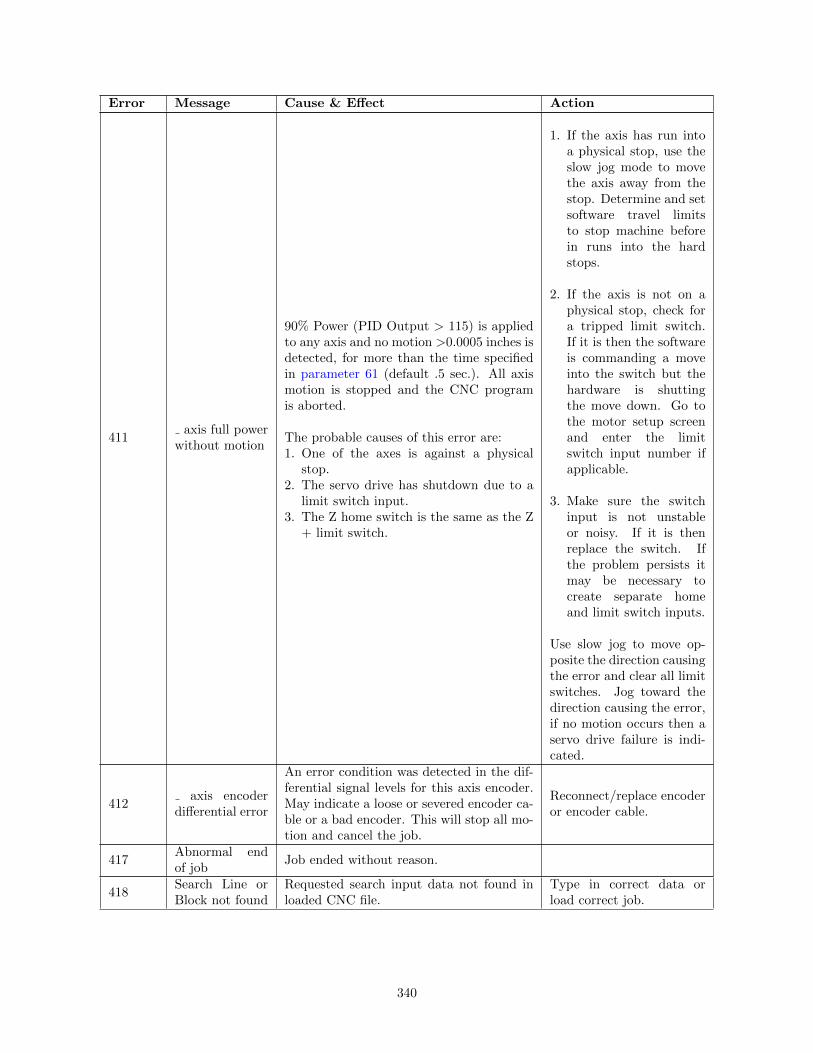
Error Message Cause & Effect Action
411axis full power
without motion
90% Power (PID Output > 115) is appliedto any axis and no motion >0.0005 inches isdetected, for more than the time specifiedin parameter 61 (default .5 sec.). All axismotion is stopped and the CNC programis aborted.
The probable causes of this error are:1. One of the axes is against a physical
stop.2. The servo drive has shutdown due to a
limit switch input.3. The Z home switch is the same as the Z
+ limit switch.
1. If the axis has run intoa physical stop, use theslow jog mode to movethe axis away from thestop. Determine and setsoftware travel limitsto stop machine beforein runs into the hardstops.
2. If the axis is not on aphysical stop, check fora tripped limit switch.If it is then the softwareis commanding a moveinto the switch but thehardware is shuttingthe move down. Go tothe motor setup screenand enter the limitswitch input number ifapplicable.
3. Make sure the switchinput is not unstableor noisy. If it is thenreplace the switch. Ifthe problem persists itmay be necessary tocreate separate homeand limit switch inputs.
Use slow jog to move op-posite the direction causingthe error and clear all limitswitches. Jog toward thedirection causing the error,if no motion occurs then aservo drive failure is indi-cated.
412axis encoder
differential error
An error condition was detected in the dif-ferential signal levels for this axis encoder.May indicate a loose or severed encoder ca-ble or a bad encoder. This will stop all mo-tion and cancel the job.
Reconnect/replace encoderor encoder cable.
417Abnormal endof job
Job ended without reason.
418Search Line orBlock not found
Requested search input data not found inloaded CNC file.
Type in correct data orload correct job.
340
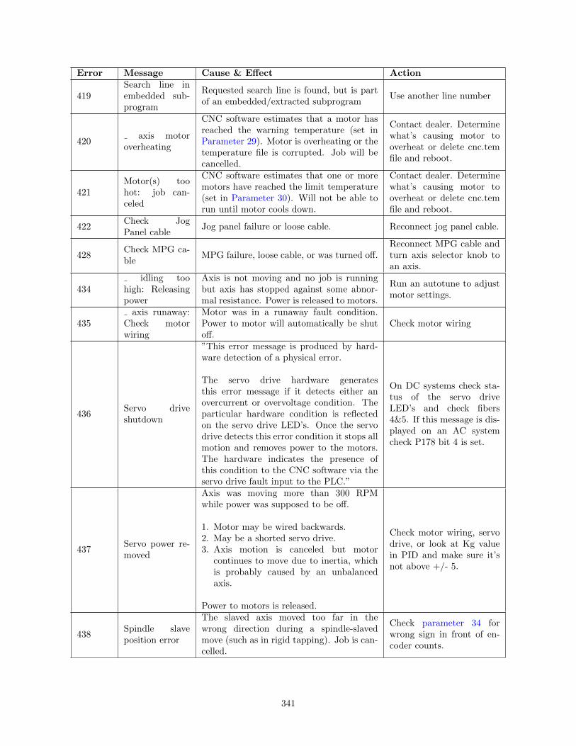
Error Message Cause & Effect Action
419Search line inembedded sub-program
Requested search line is found, but is partof an embedded/extracted subprogram
Use another line number
420axis motor
overheating
CNC software estimates that a motor hasreached the warning temperature (set inParameter 29). Motor is overheating or thetemperature file is corrupted. Job will becancelled.
Contact dealer. Determinewhat’s causing motor tooverheat or delete cnc.temfile and reboot.
421Motor(s) toohot: job can-celed
CNC software estimates that one or moremotors have reached the limit temperature(set in Parameter 30). Will not be able torun until motor cools down.
Contact dealer. Determinewhat’s causing motor tooverheat or delete cnc.temfile and reboot.
422Check JogPanel cable
Jog panel failure or loose cable. Reconnect jog panel cable.
428Check MPG ca-ble
MPG failure, loose cable, or was turned off.Reconnect MPG cable andturn axis selector knob toan axis.
434idling too
high: Releasingpower
Axis is not moving and no job is runningbut axis has stopped against some abnor-mal resistance. Power is released to motors.
Run an autotune to adjustmotor settings.
435axis runaway:
Check motorwiring
Motor was in a runaway fault condition.Power to motor will automatically be shutoff.
Check motor wiring
436Servo driveshutdown
”This error message is produced by hard-ware detection of a physical error.
The servo drive hardware generatesthis error message if it detects either anovercurrent or overvoltage condition. Theparticular hardware condition is reflectedon the servo drive LED’s. Once the servodrive detects this error condition it stops allmotion and removes power to the motors.The hardware indicates the presence ofthis condition to the CNC software via theservo drive fault input to the PLC.”
On DC systems check sta-tus of the servo driveLED’s and check fibers4&5. If this message is dis-played on an AC systemcheck P178 bit 4 is set.
437Servo power re-moved
Axis was moving more than 300 RPMwhile power was supposed to be off.
1. Motor may be wired backwards.2. May be a shorted servo drive.3. Axis motion is canceled but motor
continues to move due to inertia, whichis probably caused by an unbalancedaxis.
Power to motors is released.
Check motor wiring, servodrive, or look at Kg valuein PID and make sure it’snot above +/- 5.
438Spindle slaveposition error
The slaved axis moved too far in thewrong direction during a spindle-slavedmove (such as in rigid tapping). Job is can-celled.
Check parameter 34 forwrong sign in front of en-coder counts.
341

Error Message Cause & Effect Action
439axis servo
drive dataoutput error
Logic power failure or loss of communica-tion from the drive to the MPU11.
Is logic LED on? Checkfiber optic cables to drive.For SD1 drives, make surebus cables are shielded andare as short as possible.Power unit down and checkdrive connections.
441axis overvolt-
age
Input power has gone higher than 340VDCand will shutdown the drive and removespower. The motor brake will engage for 5seconds in this condition.
Check input voltage is be-low 340VDC. If not, incom-ing VAC needs lowered.
442axis undervolt-
ageDrive input power is less than 80 VDC. Check supply voltage.
443axis commu-
tation encoderbad
Control detected invalid commutation zonevalue
Preform a motor MoveSync in the Drive Menu.A Zero (0) or Seven (7) isan invalid zone. Check for:
1. Wiring problem inthe encoder cable ormotor end cap (brokenencoder wires).
2. Encoder cable shieldconnected at motorend, when it shouldn’tbe.
3. Bad encoder.
4. Motor power cableshields not connected.
5. Drive not groundedproperly.
444axis overtem-
perature de-tected
Drive overtemp sensor tripped. No motorpower.
The drive is being run atover capacity or the cool-ing fan is either not func-tioning or its air flow isblocked.
445axis overcur-
rent detectedOvercurrent detected on an axis. No motorpower.
Try to jog the axis. Thedrive will reset the currentlimit and try to move themotor. If the error comesback, check for a short inthe motor output.
446axis servo
drive data inputfailure
Communication Checksum error. No motorpower.
Check fiber optic cables.Verify continuity betweendrive chassis, ground stripand Earth ground.
342

Error Message Cause & Effect Action
447axis (#) bad
index pulse de-tected
Noise picked up by encoder cable or mis-aligned encoder. No motor power.
Remove noise or align theencoder.
449
Manual move-ment detectedin restrictedarea
Unexpected movement of manual axis de-tected when Z axis summing is active.
Physically lock the Z axismanual quill.
450Voltage brakeapplied
Overvoltage condition was detected. Elec-tronic braking was applied by offloading ex-cess voltage to dropping resistors.
Usually this error conditionis innocuous even if thismessage occurs every oncein a while in a job. How-ever, if this message occursin a continuous stream,contact your dealer.
451Current brakeapplied
Overcurrent spike was detected on thedrive.
Usually this error conditionis innocuous even if thismessage occurs every oncein a while in a job. How-ever, if this message oc-curs too often, it may meanyou need a higher currentdrive. But, if this mes-sage appears in a contin-uous stream, something isseriously wrong, and youshould hit E-Stop to cutpower to the drive and thencontact your dealer.
452PC ReceiveData Error
A fatal communication error occurred be-tween the MPU and PC. The error was de-tected on the PC side.
Restart the software toclear the error. If this erroroccurs often there may bean issue with the networkconfiguration or the Ether-net cable.
453CPU ReceiveData Error
A fatal communication error occurred be-tween the MPU and PC. The error was de-tected on the MPU11 side
Restart the software toclear the error. If this erroroccurs often there may bean issue with the networkconfiguration or the Ether-net cable.
453Jogging whileprobe detected
The probe was in the tripped state while ajog key was pressed.
454axis scaleencoder differ-ential error
An error condition was detected in the dif-ferential signal levels for this axis scale en-coder. May indicate a loose or severed en-coder cable or a bad encoder. This will stopall motion and cancel the job.
Reconnect/replace scaleencoder or scale encodercable.
455axis encoderquadratureerror
The axis encoder skipped a transition stateon its count-up/count-down sequence. Mayindicate a bad encoder or a loose or severedencoder cable. This will stop all motion andcancel the job.
Reconnect/replace encoderor encoder cable.
343
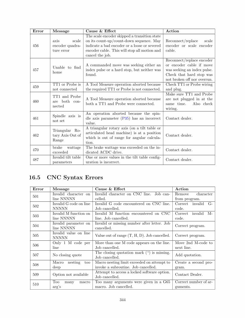
Error Message Cause & Effect Action
456axis scaleencoder quadra-ture error
The scale encoder skipped a transition stateon its count-up/count-down sequence. Mayindicate a bad encoder or a loose or severedencoder cable. This will stop all motion andcancel the job.
Reconnect/replace scaleencoder or scale encodercable.
457Unable to findhome
A commanded move was seeking either anindex pulse or a hard stop, but neither wasfound.
Reconnect/replace encoderor encoder cable if movewas seeking an index pulse.Check that hard stop wasnot broken off nor overrun.
459TT1 or Probe isnot connected
A Tool Measure operation aborted becausethe required TT1 or Probe is not connected.
Check TT1 or Probe wiringand plug.
460TT1 and Probeare both con-nected
A Tool Measure operation aborted becauseboth a TT1 and Probe were connected.
Make sure TT1 and Probeare not plugged in at thesame time. Also checkwiring.
461Spindle axis isnot set
An operation aborted because the spin-dle axis parameter (P35) has an incorrectvalue.
Contact dealer.
462Triangular Ro-tary Axis Out ofRange
A triangular rotary axis (on a tilt table orarticulated head machine) is at a positionwhich is out of range for angular calcula-tion.
Contact dealer.
470brake wattageexceeded
The brake wattage was exceeded on the in-dicated ACDC drive.
Contact dealer.
487Invalid tilt tableparameters
One or more values in the tilt table config-uration is incorrect.
Contact dealer.
16.5 CNC Syntax Errors
Error Message Cause & Effect Action
501Invalid character online NNNNN
Invalid character on CNC line. Job can-celled.
Remove characterfrom program.
502Invalid G code on lineNNNNN
Invalid G code encountered on CNC line.Job cancelled.
Correct invalid G-code.
503Invalid M function online NNNNN
Invalid M function encountered on CNCline. Job cancelled.
Correct invalid M-code.
504Invalid parameter online NNNNN
Invalid or missing number after letter. Jobcancelled.
Correct program.
505Invalid value on lineNNNNN
Value out of range (T, H, D). Job cancelled. Correct program.
506Only 1 M code perline
More than one M code appears on the line.Job cancelled.
Move 2nd M-code tonext line.
507 No closing quoteThe closing quotation mark (“) is missing.Job cancelled.
Add quotation.
508Macro nesting toodeep
Macro nesting limit exceeded on attempt toinvoke a subroutine. Job cancelled.
Create a second pro-gram.
509 Option not availableAttempt to access a locked software option.Job cancelled.
Contact Dealer.
510Too many macroarg’s
Too many arguments were given in a G65macro. Job cancelled.
Correct number of ar-guments.
344
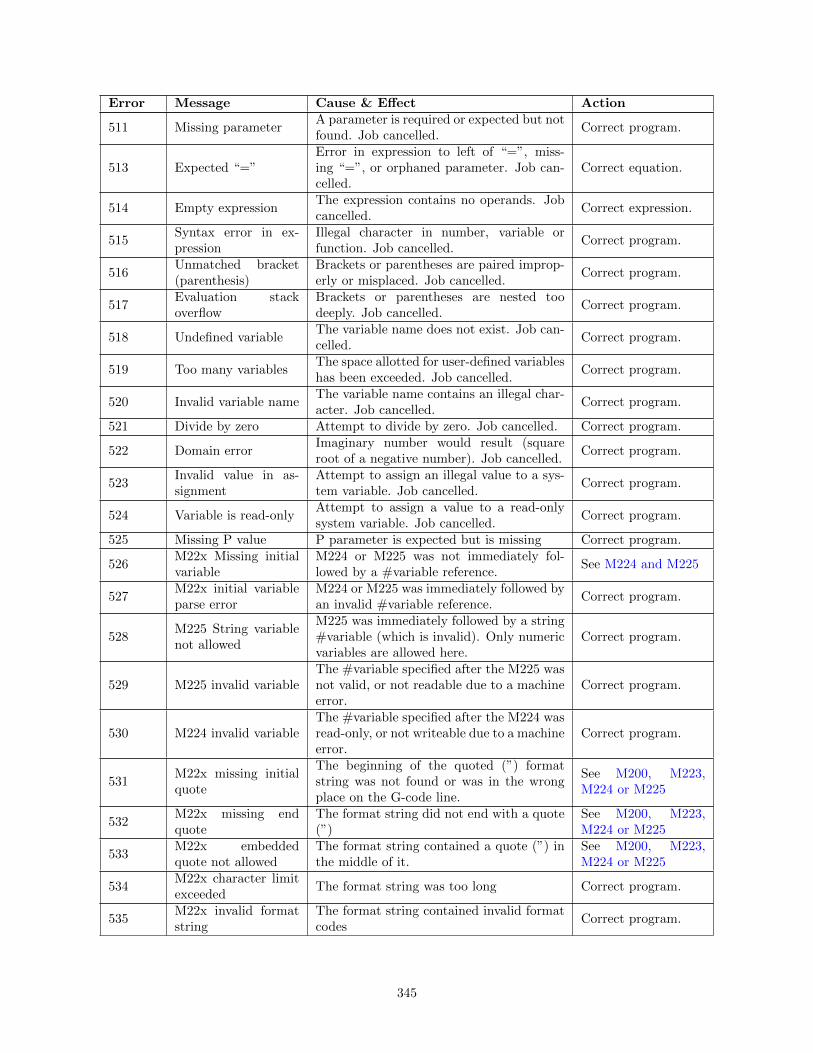
Error Message Cause & Effect Action
511 Missing parameterA parameter is required or expected but notfound. Job cancelled.
Correct program.
513 Expected “=”Error in expression to left of “=”, miss-ing “=”, or orphaned parameter. Job can-celled.
Correct equation.
514 Empty expressionThe expression contains no operands. Jobcancelled.
Correct expression.
515Syntax error in ex-pression
Illegal character in number, variable orfunction. Job cancelled.
Correct program.
516Unmatched bracket(parenthesis)
Brackets or parentheses are paired improp-erly or misplaced. Job cancelled.
Correct program.
517Evaluation stackoverflow
Brackets or parentheses are nested toodeeply. Job cancelled.
Correct program.
518 Undefined variableThe variable name does not exist. Job can-celled.
Correct program.
519 Too many variablesThe space allotted for user-defined variableshas been exceeded. Job cancelled.
Correct program.
520 Invalid variable nameThe variable name contains an illegal char-acter. Job cancelled.
Correct program.
521 Divide by zero Attempt to divide by zero. Job cancelled. Correct program.
522 Domain errorImaginary number would result (squareroot of a negative number). Job cancelled.
Correct program.
523Invalid value in as-signment
Attempt to assign an illegal value to a sys-tem variable. Job cancelled.
Correct program.
524 Variable is read-onlyAttempt to assign a value to a read-onlysystem variable. Job cancelled.
Correct program.
525 Missing P value P parameter is expected but is missing Correct program.
526M22x Missing initialvariable
M224 or M225 was not immediately fol-lowed by a #variable reference.
See M224 and M225
527M22x initial variableparse error
M224 or M225 was immediately followed byan invalid #variable reference.
Correct program.
528M225 String variablenot allowed
M225 was immediately followed by a string#variable (which is invalid). Only numericvariables are allowed here.
Correct program.
529 M225 invalid variableThe #variable specified after the M225 wasnot valid, or not readable due to a machineerror.
Correct program.
530 M224 invalid variableThe #variable specified after the M224 wasread-only, or not writeable due to a machineerror.
Correct program.
531M22x missing initialquote
The beginning of the quoted (”) formatstring was not found or was in the wrongplace on the G-code line.
See M200, M223,M224 or M225
532M22x missing endquote
The format string did not end with a quote(”)
See M200, M223,M224 or M225
533M22x embeddedquote not allowed
The format string contained a quote (”) inthe middle of it.
See M200, M223,M224 or M225
534M22x character limitexceeded
The format string was too long Correct program.
535M22x invalid formatstring
The format string contained invalid formatcodes
Correct program.
345
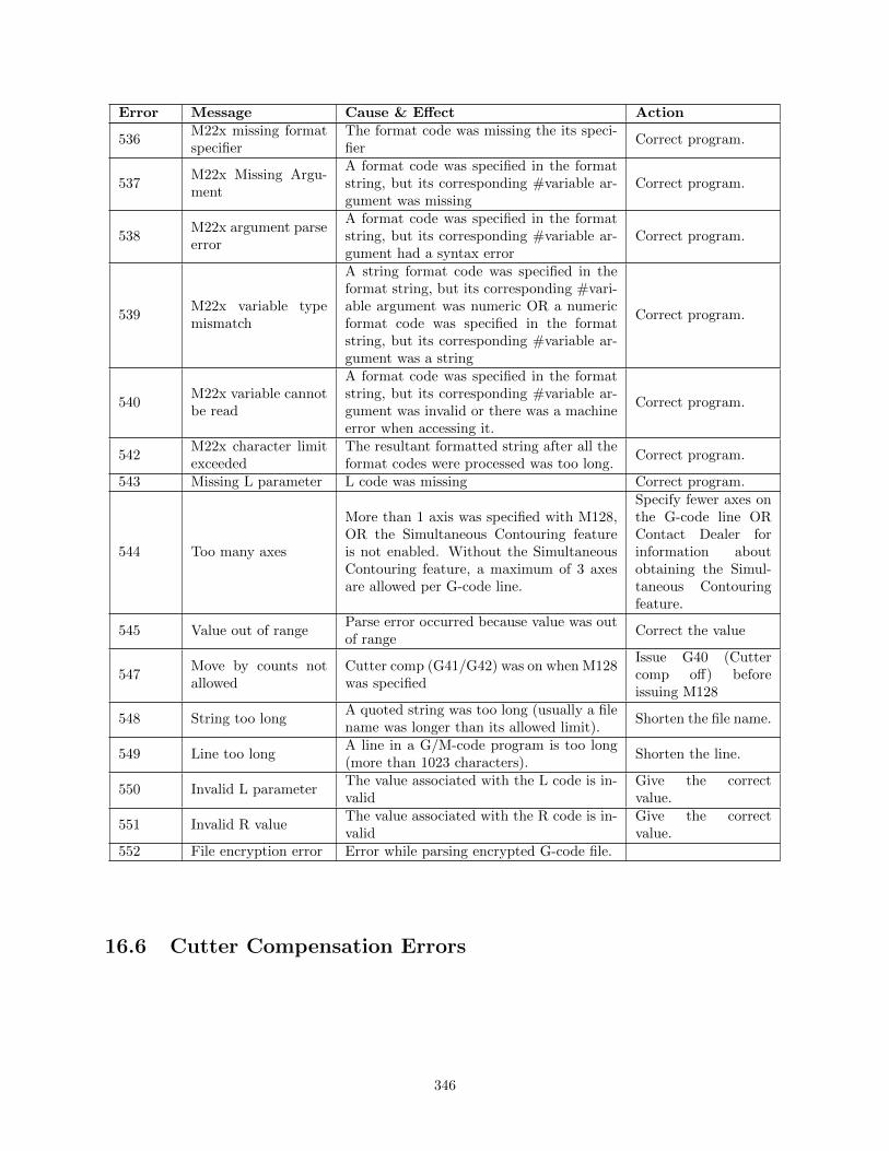
Error Message Cause & Effect Action
536M22x missing formatspecifier
The format code was missing the its speci-fier
Correct program.
537M22x Missing Argu-ment
A format code was specified in the formatstring, but its corresponding #variable ar-gument was missing
Correct program.
538M22x argument parseerror
A format code was specified in the formatstring, but its corresponding #variable ar-gument had a syntax error
Correct program.
539M22x variable typemismatch
A string format code was specified in theformat string, but its corresponding #vari-able argument was numeric OR a numericformat code was specified in the formatstring, but its corresponding #variable ar-gument was a string
Correct program.
540M22x variable cannotbe read
A format code was specified in the formatstring, but its corresponding #variable ar-gument was invalid or there was a machineerror when accessing it.
Correct program.
542M22x character limitexceeded
The resultant formatted string after all theformat codes were processed was too long.
Correct program.
543 Missing L parameter L code was missing Correct program.
544 Too many axes
More than 1 axis was specified with M128,OR the Simultaneous Contouring featureis not enabled. Without the SimultaneousContouring feature, a maximum of 3 axesare allowed per G-code line.
Specify fewer axes onthe G-code line ORContact Dealer forinformation aboutobtaining the Simul-taneous Contouringfeature.
545 Value out of rangeParse error occurred because value was outof range
Correct the value
547Move by counts notallowed
Cutter comp (G41/G42) was on when M128was specified
Issue G40 (Cuttercomp off) beforeissuing M128
548 String too longA quoted string was too long (usually a filename was longer than its allowed limit).
Shorten the file name.
549 Line too longA line in a G/M-code program is too long(more than 1023 characters).
Shorten the line.
550 Invalid L parameterThe value associated with the L code is in-valid
Give the correctvalue.
551 Invalid R valueThe value associated with the R code is in-valid
Give the correctvalue.
552 File encryption error Error while parsing encrypted G-code file.
16.6 Cutter Compensation Errors
346

Error Message Cause & Effect Action
601Error: no compensa-tion in MDI
G41 or G42 entered in MDI. MDI is notcanceled, but cutter compensation doesNOT go into effect. Remainder of line pro-cessed.
Do not use G41 orG42 in MDI.
603Arc as first uncomp.move on line NNNNN
Arc specified as first move after end of com-pensation (G40). Job cancelled.
First move after G40must be a linearmove.
604Plane must be XY online NNNNN
Cutter compensation started with YZ orZX plane selected. Job cancelled.
Remove cutter comp.for YZ or ZX planemoves, option is notavailable.
605Canned cycle notallowed on lineNNNNN
Canned cycle attempted during compensa-tion. Job cancelled.
Do not use cuttercomp. with cannedcycles.
606G53 not allowed online NNNNN
G53 attempted during compensation. Jobcancelled.
Choose a differentwork coordinate.
607Set home not allowedon line NNNNN
M26 attempted during compensation. Jobcancelled.
Do not use M26 withcutter comp.
608Ref. point movenot allowed on lineNNNNN
G28, G29, or G30 attempted during com-pensation. Job cancelled.
Do not use returnpoints with cuttercomp.
16.7 Parameter Setting Errors
Error Message Cause & Effect Action
701G10 error: no R-valueon line NNNNN
G10 used with no R-value. Job cancelled. Input an R-value.
702G10 error: invalid Don line NNNNN
Job cancelled (D0 cannot be set; it is alwayszero).
Change D to a validvalue.
703G10 error: invalid Hon line NNNNN
G10 H0 Rxx specified. Job canceled (H0cannot be set; it is always zero).
Change H to a validvalue.
704G10 error: invalid Pon line NNNNN
G10 used with unknown P value. Job can-celled.
Change P to a validvalue.
705G10 error: No D, H,or P on line NNNNN
G10 used without D, H, or P to assignvalue. Job cancelled.
Add appropriate D,H, or P value.
16.8 Canned Cycle Errors
Error Message Cause & Effect Action
801Error: No R point online NNNNN
No R-value specified. Job cancelled. Add an R-point.
802Error: Q = 0 on lineNNNNN
Q value of 0 specified (Q used for G73 andG83 only). Job cancelled.
Insert a Q non-zerovalue.
803Error: No Z point online NNNNN
No Z value specified for canned cycle. Jobcancelled.
Add a Z-value.
347

Error Message Cause & Effect Action
804Error: Ggg invalid online NNNNN (gg =76, 86, 87, 88)
Unimplemented canned cycle requested.Job cancelled.
Change to a valid G-code.
805Error: No Q value online NNNNN
Q value not specified for G73 or G83. Jobcancelled.
Insert a Q-value.
806Error: No P value online NNNNN
P value (dwell time) not specified for G82or G89. Job cancelled.
Add a P-value.
807Error: Cannot exe-cute G when axis Bis rotated
On an Articulated Head machine withTWCS feature enabled, a non-compoundcanned cycle (such as G73, G74, G76, G80,G81, G82, G83, G84, G85, G89) was issuedon a WCS that was set to TWCS=No whilethe spindle head was tilted (i.e. rotary Baxis was not 0). Job cancelled.
Either move B to 0 orissue the compoundcanned cycle versionof the erroneous G-code such as G173,G174, G176, G181,G182, G183, G184,G185, G189.
16.9 Miscellaneous Errors / Messages
Error Message Cause & Effect Action
901Ref. point invalid online NNNNN
G30 with invalid P value (must be 1 or 2).Job cancelled.
Change P-value to a 1or 2.
902No prior G28 or G30on line NNNNN
G29 with no preceding G28 or G30. Add a G29 or G30.
903Warning: No coordi-nates for G92 on lineNNNNN
G92 with no axis coordinates to set. Re-mainder of line processed; job continues.
Add coordinates.
905Warning: 0 radius arcon line NNNNN
Arc move was specified with a zero radius.Move is done as a linear move; job contin-ues.
Specify a radius.
906Warning: unknownarc on line NNNNN
Position of arc move could not be deter-mined from parameters (e.g. G91 G2 X0Y0 R1). Move is done as a linear move; jobcontinues.
Correct program.
907axis travel exceeded
on line NNNNNSoftware travel limit would be exceeded bythe requested move. Job cancelled.
Check program, partzero or tool offset.
909Program too long:job canceled
Attempt to run a job over 1MB in length,without the unlimited program size option.Job cancelled.
Contact Dealer orbreak up program.
910No subroutines inMDI
Specified O9100 - O9999 in MDI, whichwould begin an embedded subprogram.MDI cancelled.
911 Illegal recursionAttempt to execute a subprogram or macrothat calls itself, either directly or indirectly.Job cancelled.
Call correct subpro-gram.
913Could not open filefilename.ext
Attempt to call a subprogram or macro, butthe subprogram file does not exist. Job can-celled.
Make sure file name iscorrect and is in thencfiles directory.
348

Error Message Cause & Effect Action
915DSP window retry sNfN rN
DSP window checking failed, move will berepeated unless the maximum retries havebeen reached, s = number of successes, f =number of failures, r = number of times themaximum retry value has been reached
916Unexpected probecontact
probed tripped when a cycle did not ex-pected contact
917Invalid tilt lookup ta-ble
The tilt lookup table file (tilt.tab) has aninvalid format or if it is not found
918Probe unable to de-tect surface
Probe travelled maximum distance with-out contact, dsp window checking failed, orprobe repeatability failed.
919DSP window failedmaximum retries
DSP probe reached the maximum retrylimit without a successful window
920Unable to clear obsta-cle
Probing cycle failed to clear an obstacle
921Unable to determinecorner
Probing cycle failed to find corner (insideand outside corner)
922 Out of memory problem allocating memory923 Error: Z home not set Z home is not set
924 File read errorProblem reading the job file, this error oc-curs if the file was opened successfully butthere was an error while reading the file.
925 Error reading job filesame as above at a different place in thecode
926Failed to locate jobcontinuation position
Job continuation from the Run Menu failed. Do a Run/Search
927Too many subpro-gram calls
Nesting level of subprograms is too high.I.e. a subprogram calls another subprogramwhich calls another subprogram, which callsanother subprogram, etc. . .
928Error Loading LogConfiguration file. . .Using defaults
There was an error while loading the logconfiguration file. Default settings will beused.
929 Log Level set toThe logging level parameter (P140) hasbeen changed.
930
Log Level Configura-tion file not found. . .Creating new configu-ration.
The log level configuration file was notfound. A default file will be created.
932Error during ToolCheck
A general error condition occurred whenthe Tool Check key was pressed.
933 Log file initializedThere was an error in trimming the log file,or the log file did not exist, so a new log filehas been created.
934Warning: Excess pre-cision truncated
A CNC program is using axis positioningprecision greater than what is displayed,and therefore the actual commanded posi-tions are truncated. This happens when theSimultaneous Contouring feature was notenabled. This feature must be enabled forthe extra precision to be acknowledged.
Contact Dealer forinformation aboutobtaining the Simul-taneous Contouringfeature.
349

Error Message Cause & Effect Action
935axis (#) scale dis-
abled
A scale is enabled for this axis but compen-sation was disabled. Scale compensation isdisabled at initial power up, configurationchanges, and during homing moves.
Home the machine.
935Probe failed reset re-tries
Probe failed to reset after 3 tries. The prob-ing operation may have been started tooclose to the surface.
Move probe furtheraway from surfaceand do probing op-eration again. Ifthis continues tofail persistently, calldealer.
936axis (#) scale en-
abled
A scale is enabled for this axis and com-pensation was enabled. This happens afterhoming the axis.
Not Applicable
936 Probe failed to resetProbe failed to reset. The probing opera-tion may have been started too close to thesurface.
Move probe furtheraway from surfaceand do probing op-eration again. Ifthis continues tofail persistently, calldealer.
944MPU requested re-send
The MPU requested a resend Status Message
945 PC requested resend The PC requested a resend Status Message946 PC resending The PC is resending Status Message
947PC received data outof order
The PC needed to reorder data receivedfrom the MPU
Status Message
948 PC packet errorThe PC received bad data from the MPUand will try to recover by requesting a re-send.
Status Message
949Drive map does notmatch hardware
One or more of the drive mapping parame-ters 300-307 is misconfigured
Contact Dealer.
16.10 Scaling/Mirroring Errors
Error Message Cause & Effect Action
1001Invalid scaling pa-rameter on lineNNNNN
Invalid parameter specified (I, J, K, P). Jobcancelled.
Remove or change in-valid parameter.
1002Invalid scaling centeron line NNNNN
Invalid parameter specified (X, Y, Z). Jobcancelled.
Remove or change in-valid parameter.
1003G-code not allowedwhen scaling on lineNNNNN
G28/G29/G30/G92 is not allowed whenscaling or mirroring is turned on. Job can-celled.
Move G-code to ap-propriate line.
1004Turn scaling off be-fore rescaling
Tried to rescale while scaling is turned on.Job cancelled.
Turn scaling off, thenrescale.
1005Cannot scale arcswith different scalefactors
Scaling factors of the arc axes are different.Job cancelled.
Correct scaling fac-tors, or separate scal-ing operations.
350

Error Message Cause & Effect Action
1100-1199
Custom messages defined in cncxmsg.txt. Please contact your dealer if you have anyquestions regarding a particular message. This style of message should be replacedwith plcmsg.txt format on MPU11 systems.
16.11 Configuration Modification Messages
Error Message Cause & Effect111 modified: → An axis configuration parameter was modified.444 modified: → A servo drive configuration parameter was modified.555 modified: → A PID configuration parameter was modified.556 Axis converted: → A PID configuration parameter was converted.777 modified: → An axis configuration parameter was modified.888 G30 Z modified: → Z coordinate of Secondary Reference Point was modified.
999Parm # modified: →
A machine parameter was modified.
351


![ALIGNMENT SCHEMATIC PLAN - New Jersey...centroid n - [(centroid n - grid n)/combine scale factor]=north value modified local project coordinates centroid e - [(centroid e - grid e)/combined](https://img.pdfslide.us/doc/110x75/5ee18361ad6a402d666c5e4d/alignment-schematic-plan-new-jersey-centroid-n-centroid-n-grid-ncombine.jpg)