Embed Size (px)
Citation preview

Central Processing Unit/Graphics Processing Unit
(CPU/GPU) Hybrid Computing of
Synthetic Aperture Radar Algorithm
by Song Jun Park and Dale Shires
ARL-TR-5074 February 2010
Approved for public release; distribution is unlimited.
NOTICES
Disclaimers
The findings in this report are not to be construed as an official Department of the Army position unless
so designated by other authorized documents.
Citation of manufacturer’s or trade names does not constitute an official endorsement or approval of the
use thereof.
Destroy this report when it is no longer needed. Do not return it to the originator.
Army Research Laboratory Aberdeen Proving Ground, MD 21005-5069
ARL-TR-5074 February 2010
Central Processing Unit/Graphics Processing Unit
(CPU/GPU) Hybrid Computing of
Synthetic Aperture Radar Algorithm
Song Jun Park and Dale Shires
Computational and Information Sciences Directorate, ARL
Approved for public release; distribution is unlimited.
ii
REPORT DOCUMENTATION PAGE Form Approved OMB No. 0704-0188
Public reporting burden for this collection of information is estimated to average 1 hour per response, including the time for reviewing instructions, searching existing data sources, gathering and maintaining the data needed, and completing and reviewing the collection information. Send comments regarding this burden estimate or any other aspect of this collection of information, including suggestions for reducing the burden, to Department of Defense, Washington Headquarters Services, Directorate for Information Operations and Reports (0704-0188), 1215 Jefferson Davis Highway, Suite 1204, Arlington, VA 22202-4302. Respondents should be aware that notwithstanding any other provision of law, no person shall be subject to any penalty for failing to comply with a collection of information if it does not display a currently valid OMB control number.
PLEASE DO NOT RETURN YOUR FORM TO THE ABOVE ADDRESS.
1. REPORT DATE (DD-MM-YYYY)
February 2010
2. REPORT TYPE
Final
3. DATES COVERED (From - To)
4. TITLE AND SUBTITLE
Central Processing Unit/Graphics Processing Unit (CPU/GPU) Hybrid Computing
of Synthetic Aperture Radar Algorithm
5a. CONTRACT NUMBER
5b. GRANT NUMBER
5c. PROGRAM ELEMENT NUMBER
6. AUTHOR(S)
Song Jun Park and Dale Shires
5d. PROJECT NUMBER
0UE11C 5e. TASK NUMBER
5f. WORK UNIT NUMBER
7. PERFORMING ORGANIZATION NAME(S) AND ADDRESS(ES)
8. PERFORMING ORGANIZATION REPORT NUMBER
ARL-TR-5074
9. SPONSORING/MONITORING AGENCY NAME(S) AND ADDRESS(ES)
U.S. Army Research Laboratory
ATTN: RDRL-CIH-C
Aberdeen Proving Ground, MD 21005-5067
10. SPONSOR/MONITOR’S ACRONYM(S)
11. SPONSOR/MONITOR'S REPORT
NUMBER(S)
12. DISTRIBUTION/AVAILABILITY STATEMENT
Approved for public release; distribution is unlimited.
13. SUPPLEMENTARY NOTES
14. ABSTRACT
Graphics Processing Unit’s (GPU’s) powerful compute engine is leveraged to enhance the stand-alone capability of a central
processing unit (CPU). Synthetic Aperture Radar (SAR) algorithm is analyzed and implemented to execute on a system
equipped with a graphics card. Being a combined CPU/GPU solution, optimizations were applied to both architectures for
optimal hardware utilization.
15. SUBJECT TERMS
radar, multicore, GPU, image reconstruction, back-projection, parallel computing
16. SECURITY CLASSIFICATION OF: 17. LIMITATION
OF ABSTRACT
UU
18. NUMBER
OF PAGES
26
19a. NAME OF RESPONSIBLE PERSON
Song Jun Park a. REPORT
UNCLASSIFIED
b. ABSTRACT
UNCLASSIFIED
c. THIS PAGE
UNCLASSIFIED 19b. TELEPHONE NUMBER (Include area code)
410-278-5444
Standard Form 298 (Rev. 8/98)
Prescribed by ANSI Std. Z39.18
iii
Contents
Acknowledgements v
1. Introduction 1
2. Algorithm for the Synthetic Aperture Radar 1
3. Parallelizing CPU Code 3
4. Compute Unified Device Architecture (CUDA) 4
5. GPU Implementation 5
5.1 Basic Textbook Optimizations ..........................................................................................5
5.2 Memory Optimizations .....................................................................................................6
5.3 Data Reuse ........................................................................................................................6
5.4 Ratio of Computation to Memory .....................................................................................7
5.5 Increasing Assigned Parallelism .......................................................................................8
5.6 Output Discrepancies ........................................................................................................8
6. Results 9
6.1 CPU Back-projection Results ...........................................................................................9
6.2 GPU CUDA Back-projection Results .............................................................................10
6.3 Hybrid Radar Processing Results....................................................................................11
7. Recursive Sidelobe Minimization (RSM) 12
7.1 Optimizations for CUDA RSM ......................................................................................12
7.2 RSM Imaging Technique Results ...................................................................................14
8. Conclusion 14
9. References 16
List of Symbols, Abbreviations, and Acronyms 17
Distribution List 18
iv
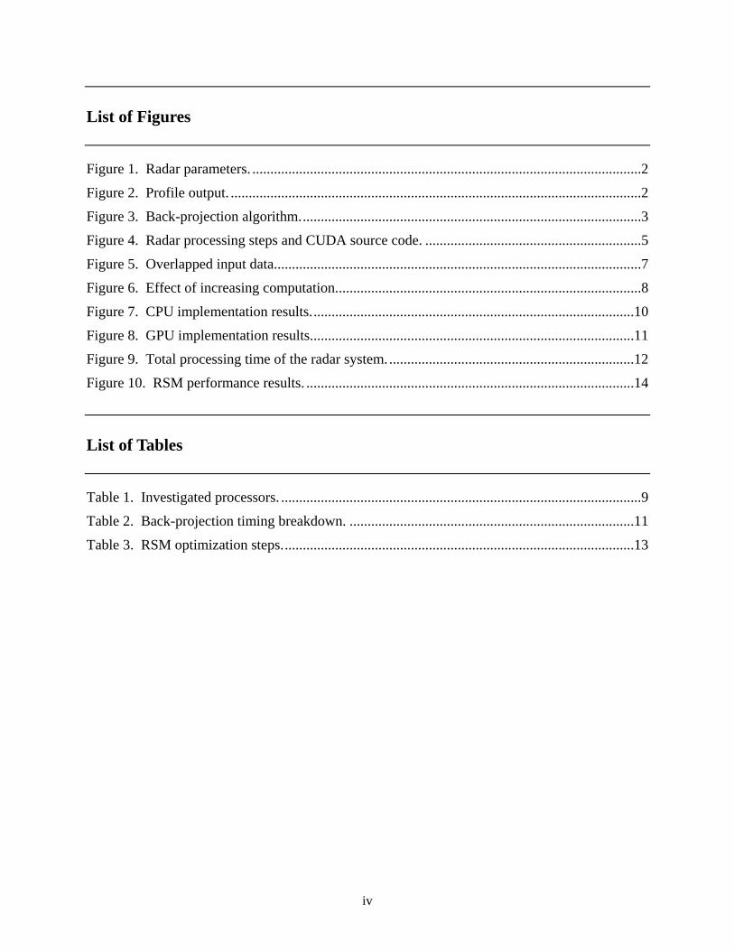
List of Figures
Figure 1. Radar parameters. ............................................................................................................2
Figure 2. Profile output. ..................................................................................................................2
Figure 3. Back-projection algorithm. ..............................................................................................3
Figure 4. Radar processing steps and CUDA source code. ............................................................5
Figure 5. Overlapped input data......................................................................................................7
Figure 6. Effect of increasing computation. ....................................................................................8
Figure 7. CPU implementation results. .........................................................................................10
Figure 8. GPU implementation results. .........................................................................................11
Figure 9. Total processing time of the radar system. ....................................................................12
Figure 10. RSM performance results. ...........................................................................................14
List of Tables
Table 1. Investigated processors. ....................................................................................................9
Table 2. Back-projection timing breakdown. ...............................................................................11
Table 3. RSM optimization steps. .................................................................................................13
v
Acknowledgements
The authors would like to thank James Ross for the programming and development of OpenMP
and Pthread implementations. He was able to apply a number of optimizations to enhance the
speed of the algorithm.
The authors wish to thank Dr. David Richie, User Productivity Enhancement and Technology
Transfer (PET) effort of the Department of Defense (DoD) High Performance Computing
Modernization Office (HPCMO). Dr. Richie is an on-site researcher at the U.S. Army Research
Laboratory (ARL) in the area of Electronics, Networking, and Systems/Command, Control,
Communications, Computers, & Intelligence (ENS/C4I). He provided valuable insights into new
application program interfaces (APIs) and directions for graphics processing units (GPUs) being
produced by Advanced Micro Devices, Inc. (AMD).
The authors wish to acknowledge the research collaboration with Lam Nguyen in the Sensors
and Electron Devices Directorate (SEDD) at ARL. The radar system provided an excellent test
bed and application to apply new heterogeneous computing capabilities to battlefield
applications like obstacle detection and avoidance.
vi
INTENTIONALLY LEFT BLANK.
1
1. Introduction
Graphics processing units (GPUs) are the most common accelerators found in today’s computing
systems. All modern computer systems host some sort of a GPU processor ranging from low-
end integrated video processors to high-end peripheral component interconnect (PCI)-Express
graphics cards. Due to its highly parallel and demanding computational requirement of graphics
applications, a dedicated processor known as a GPU assists a central processor in video
processing. This specialized nature of GPUs for computing display operations makes GPUs
faster than central processing units (CPUs) at graph-like problems with an ample amount of data
parallelism.
As evidenced by architectural differences, purposes and goals are different for GPUs and CPUs.
The major difference in terms of chip’s real estate is the allocation of processing elements and
cache. For example, out of 291 million transistors, 19 million are dedicated to execution core in
Intel Core 2 Duo processors (1) and about half of chip’s area is designated for cache. On the
other hand, GPUs typically have hundreds of floating-point execution units and large context
switch information storage space, resulting in a small area remaining for cache. The goal of a
GPU architecture design is to employ hardware multithreading and single instruction multiple
data (SIMD) execution.
Supported behind the driving market force of video game industry, GPU processors have become
inexpensive and powerful piece of silicon. As of January 2009, Nvidia’s GeForce GTX 285
graphics cards are rated at slightly above teraflop of computing power. Such capability opens an
opportunity for an unconventional high performance computing with GPU technology. The
power of supercomputing is now possible in a smaller footprint at a reduced cost by leveraging
graphic processor’s powerful engine. Originally designed for processing graphics, the role of a
GPU is increasingly targeting general-purpose and data-parallel applications (2).
2. Algorithm for the Synthetic Aperture Radar
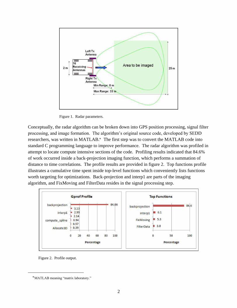
The ultra-wideband synthetic aperture radar system has been developed and mounted on a
vehicle for a prototype and testing by researchers at Sensors and Electron Devices Directorate
(SEDD). The radar is designed for obstacle avoidance and concealed target detection. Specific
parameter details are outlined in figure 1. The radar’s platform is equipped with two transmitting
antenna and an array of sixteen receiving antennas. An advantage of this radar is its ability to
operate with relatively slow and inexpensive analog to digital converters, making the system
affordable. Further detailed information regarding to the specifics of the radar system is
described in (3).
2
Figure 1. Radar parameters.
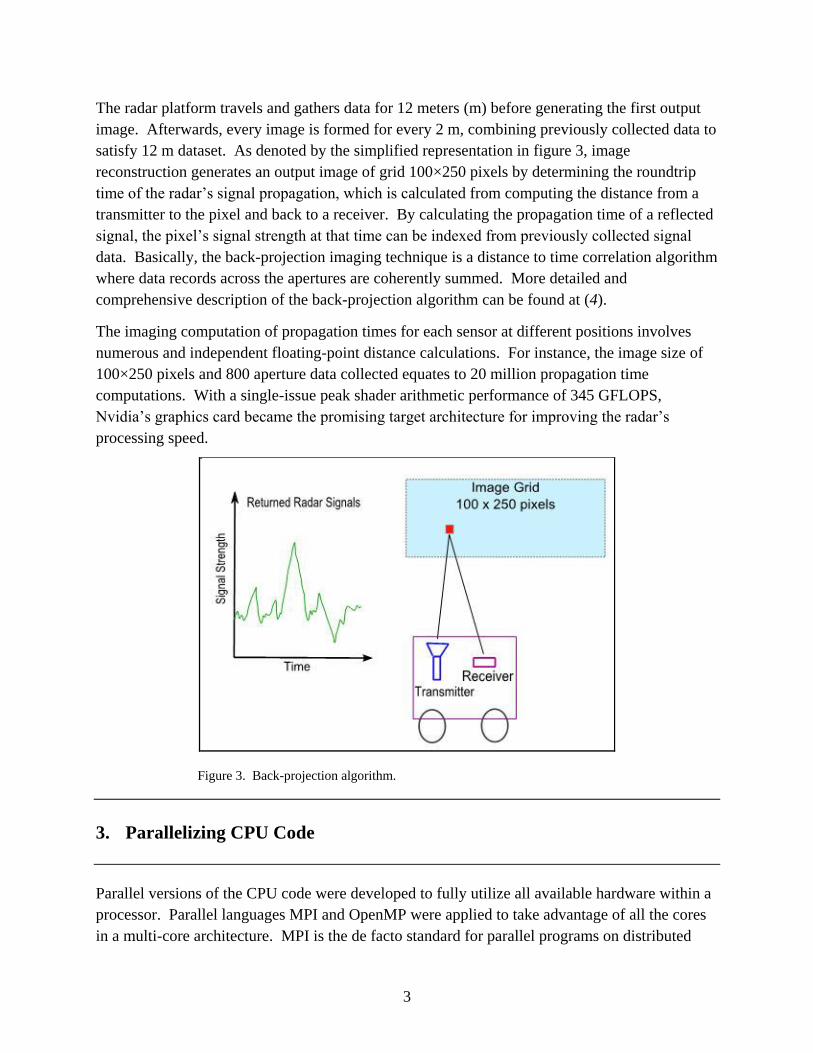
Conceptually, the radar algorithm can be broken down into GPS position processing, signal filter
processing, and image formation. The algorithm’s original source code, developed by SEDD
researchers, was written in MATLAB. The first step was to convert the MATLAB code into
standard C programming language to improve performance. The radar algorithm was profiled in
attempt to locate compute intensive sections of the code. Profiling results indicated that 84.6%
of work occurred inside a back-projection imaging function, which performs a summation of
distance to time correlations. The profile results are provided in figure 2. Top functions profile
illustrates a cumulative time spent inside top-level functions which conveniently lists functions
worth targeting for optimizations. Back-projection and interp1 are parts of the imaging
algorithm, and FixMoving and FilterData resides in the signal processing step.
Figure 2. Profile output.
MATLAB meaning “matrix laboratory.”
3
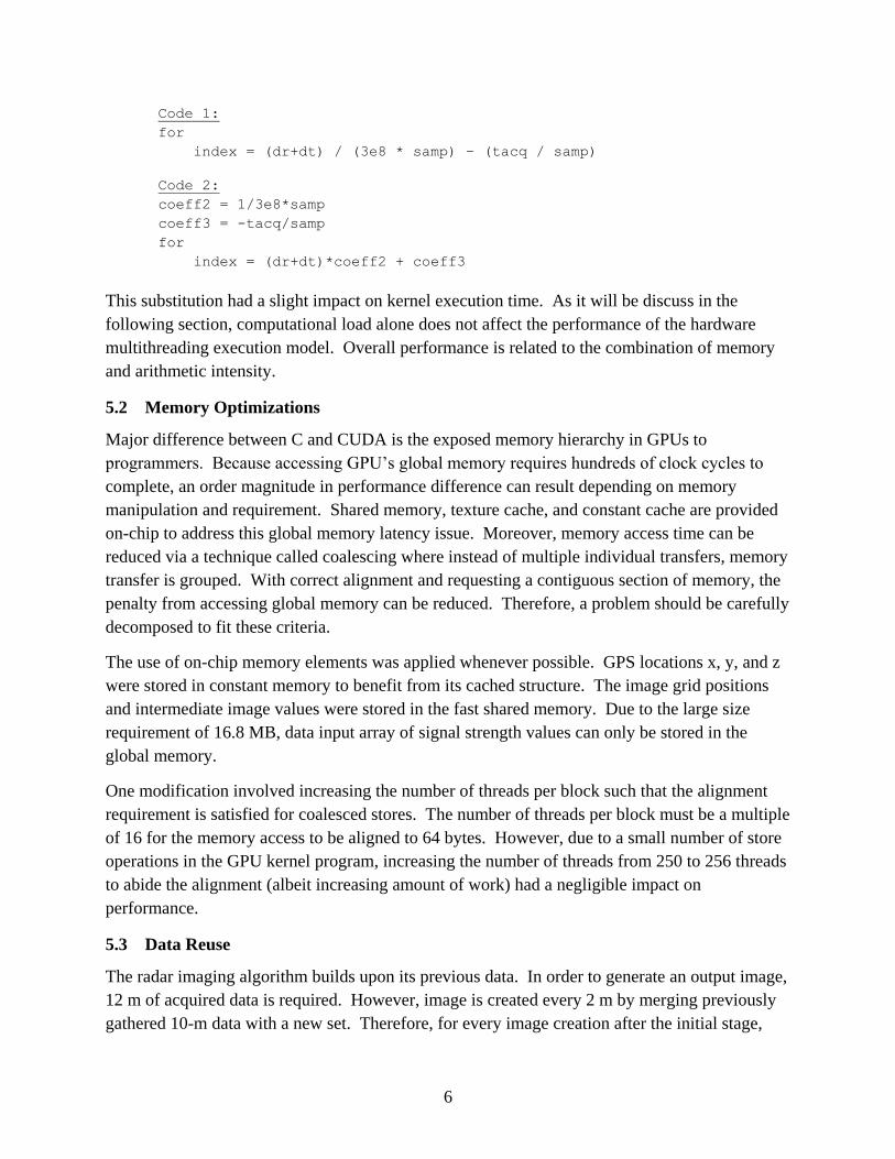
The radar platform travels and gathers data for 12 meters (m) before generating the first output
image. Afterwards, every image is formed for every 2 m, combining previously collected data to
satisfy 12 m dataset. As denoted by the simplified representation in figure 3, image
reconstruction generates an output image of grid 100×250 pixels by determining the roundtrip
time of the radar’s signal propagation, which is calculated from computing the distance from a
transmitter to the pixel and back to a receiver. By calculating the propagation time of a reflected
signal, the pixel’s signal strength at that time can be indexed from previously collected signal
data. Basically, the back-projection imaging technique is a distance to time correlation algorithm
where data records across the apertures are coherently summed. More detailed and
comprehensive description of the back-projection algorithm can be found at (4).
The imaging computation of propagation times for each sensor at different positions involves
numerous and independent floating-point distance calculations. For instance, the image size of
100×250 pixels and 800 aperture data collected equates to 20 million propagation time
computations. With a single-issue peak shader arithmetic performance of 345 GFLOPS,
Nvidia’s graphics card became the promising target architecture for improving the radar’s
processing speed.
Figure 3. Back-projection algorithm.
3. Parallelizing CPU Code
Parallel versions of the CPU code were developed to fully utilize all available hardware within a
processor. Parallel languages MPI and OpenMP were applied to take advantage of all the cores
in a multi-core architecture. MPI is the de facto standard for parallel programs on distributed

4
memory systems. It allows many compute systems to communicate by communications protocol
API. As for OpenMP, it is designed for multiprocessing on shared memory architectures. Here,
method of parallelization is achieved through the implementation of multithreading. Multi-core
parallelized versions of the back-projection routine were written in both MPI and OpenMP for
comparison analysis.
To further improve the processing speed of the CPU implementation, streaming SIMD
extensions (SSE) operations were incorporated to assign work to all available floating-point
execution units within Intel and AMD processors. Introduced with Pentium III, SSE is a SIMD
instruction set extension to x86 architecture. For example, Xeon processors have eight SIMD
floating-point arithmetic logic units (ALUs) per core (two 4-width vector instructions per clock)
capable of performing 16 floating-point operations per clock for a dual-core chip. The results
will reveal that the final performance ranges greatly depending on software and programming
method, which provides a tool to control how effectively the underlying hardware can be
utilized.
4. Compute Unified Device Architecture (CUDA)
CUDA is the Nvidia’s development toolkit that allows programmers to access the massively
parallel graphics cards for general-purpose computing. It is a Nvidia’s strategy for marketing
GPU parallel computing. CUDA allows scientist and engineers to easily harness the powerful
arithmetic capabilities of GPUs in solving computationally challenging problems.
To simplify, computation on a GPU can be viewed as a three step process: copy data to a GPU
memory, operate GPU processing, and copy the results back from the GPU memory. To keep
the learning curve at minimum, Nvidia’s programming model simply adds extensions to the
popular language C. From programmer’s perspective, CUDA provides communication API for
data transfers to a GPU accelerator and a kernel function that executes on a GPU device. In this
paradigm, only a key function needs be translated into CUDA and rest of the code can remain in
C. This approach has the benefit of quick integration with CUDA programming environment.
The code that remained in C will execute in a serial manner on a CPU and when the process
reaches to a kernel, the execution of parallel GPU computing will begin. A complete CUDA
programming guide is outlined in (5). Note that a GPU is providing an assistance and hopefully
acceleration to a standalone CPU processing by working side by side in performing computation.
One of the main execution model difference between a CPU and a GPU is the hardware
multithreading. CPU processors work to execute a single instruction as fast as possible, whereas
GPU units strive to increase the throughput speed of a group of instructions. Accordingly, GPU
devices keep more active threads than the available compute resources (6). These large thread
contexts are assigned and kept for each core such that switching of a stalled thread to an

5
executable thread incurs no penalty. Instead of having a large cache to address memory latency,
GPU devices sacrifice storage space in order to keep the execution thread information.
Hardware multithreading is how a GPU hides the main memory latency taking hundreds of clock
cycles. In Nvidia hardware, the number of active threads per multiprocessor is 768 (5). Since
GeForce 8800 GTX has 16 multiprocessors, minimum of 12,288 independent threads are
recommended for optimal GPU designs.
5. GPU Implementation
For GPU mapping, the output image of 100×250 pixels was decomposed into threads where each
pixel was assigned to a GPU thread. As a result, a total of 25,000 CUDA threads were assigned
for this application. A CUDA thread is a basic work element and the total number of threads
represents the amount of parallel work. The core distance calculations consist of subtractions of
x, y, z positions, applying square root operations, and correlating distance to time with constant
division and addition. A part of source code representing the core calculations inside the CUDA
kernel of the image formation algorithm is provided in figure 4.
Figure 4. Radar processing steps and CUDA source code.
5.1 Basic Textbook Optimizations
Similar to C code optimization techniques, the computational load within the main loop of the
kernel was reduced by substituting division and constants. The code transformation is outlined
below:
6
Code 1:
for
index = (dr+dt) / (3e8 * samp) – (tacq / samp)
Code 2:
coeff2 = 1/3e8*samp
coeff3 = -tacq/samp
for
index = (dr+dt)*coeff2 + coeff3
This substitution had a slight impact on kernel execution time. As it will be discuss in the
following section, computational load alone does not affect the performance of the hardware
multithreading execution model. Overall performance is related to the combination of memory
and arithmetic intensity.
5.2 Memory Optimizations
Major difference between C and CUDA is the exposed memory hierarchy in GPUs to
programmers. Because accessing GPU’s global memory requires hundreds of clock cycles to
complete, an order magnitude in performance difference can result depending on memory
manipulation and requirement. Shared memory, texture cache, and constant cache are provided
on-chip to address this global memory latency issue. Moreover, memory access time can be
reduced via a technique called coalescing where instead of multiple individual transfers, memory
transfer is grouped. With correct alignment and requesting a contiguous section of memory, the
penalty from accessing global memory can be reduced. Therefore, a problem should be carefully
decomposed to fit these criteria.
The use of on-chip memory elements was applied whenever possible. GPS locations x, y, and z
were stored in constant memory to benefit from its cached structure. The image grid positions
and intermediate image values were stored in the fast shared memory. Due to the large size
requirement of 16.8 MB, data input array of signal strength values can only be stored in the
global memory.
One modification involved increasing the number of threads per block such that the alignment
requirement is satisfied for coalesced stores. The number of threads per block must be a multiple
of 16 for the memory access to be aligned to 64 bytes. However, due to a small number of store
operations in the GPU kernel program, increasing the number of threads from 250 to 256 threads
to abide the alignment (albeit increasing amount of work) had a negligible impact on
performance.
5.3 Data Reuse
The radar imaging algorithm builds upon its previous data. In order to generate an output image,
12 m of acquired data is required. However, image is created every 2 m by merging previously
gathered 10-m data with a new set. Therefore, for every image creation after the initial stage,
7
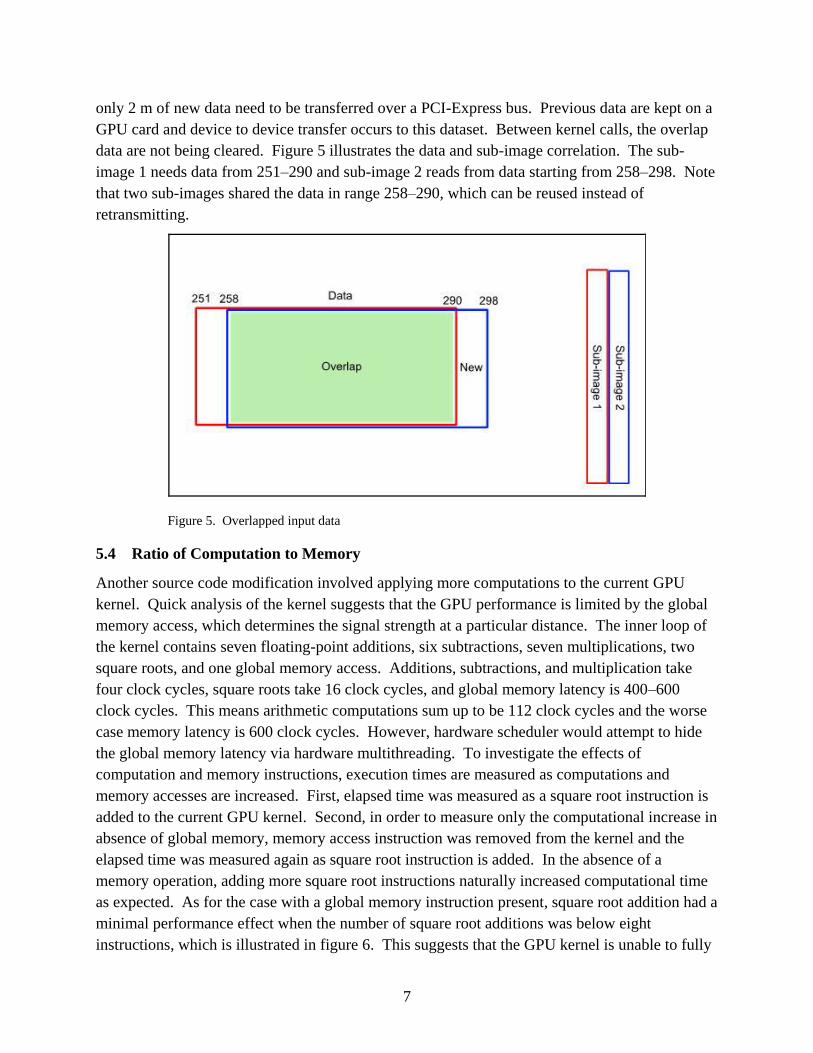
only 2 m of new data need to be transferred over a PCI-Express bus. Previous data are kept on a
GPU card and device to device transfer occurs to this dataset. Between kernel calls, the overlap
data are not being cleared. Figure 5 illustrates the data and sub-image correlation. The sub-
image 1 needs data from 251–290 and sub-image 2 reads from data starting from 258–298. Note
that two sub-images shared the data in range 258–290, which can be reused instead of
retransmitting.
Figure 5. Overlapped input data
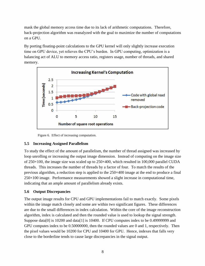
5.4 Ratio of Computation to Memory
Another source code modification involved applying more computations to the current GPU
kernel. Quick analysis of the kernel suggests that the GPU performance is limited by the global
memory access, which determines the signal strength at a particular distance. The inner loop of
the kernel contains seven floating-point additions, six subtractions, seven multiplications, two
square roots, and one global memory access. Additions, subtractions, and multiplication take
four clock cycles, square roots take 16 clock cycles, and global memory latency is 400–600
clock cycles. This means arithmetic computations sum up to be 112 clock cycles and the worse
case memory latency is 600 clock cycles. However, hardware scheduler would attempt to hide
the global memory latency via hardware multithreading. To investigate the effects of
computation and memory instructions, execution times are measured as computations and
memory accesses are increased. First, elapsed time was measured as a square root instruction is
added to the current GPU kernel. Second, in order to measure only the computational increase in
absence of global memory, memory access instruction was removed from the kernel and the
elapsed time was measured again as square root instruction is added. In the absence of a
memory operation, adding more square root instructions naturally increased computational time
as expected. As for the case with a global memory instruction present, square root addition had a
minimal performance effect when the number of square root additions was below eight
instructions, which is illustrated in figure 6. This suggests that the GPU kernel is unable to fully
8
mask the global memory access time due to its lack of arithmetic computations. Therefore,
back-projection algorithm was reanalyzed with the goal to maximize the number of computations
on a GPU.
By porting floating-point calculations to the GPU kernel will only slightly increase execution
time on GPU device, yet relieves the CPU’s burden. In GPU computing, optimization is a
balancing act of ALU to memory access ratio, registers usage, number of threads, and shared
memory.
Figure 6. Effect of increasing computation.
5.5 Increasing Assigned Parallelism
To study the effect of the amount of parallelism, the number of thread assigned was increased by
loop unrolling or increasing the output image dimension. Instead of computing on the image size
of 250×100, the image size was scaled up to 250×400, which resulted in 100,000 parallel CUDA
threads. This increases the number of threads by a factor of four. To match the results of the
previous algorithm, a reduction step is applied to the 250×400 image at the end to produce a final
250×100 image. Performance measurements showed a slight increase in computational time,
indicating that an ample amount of parallelism already exists.
5.6 Output Discrepancies
The output image results for CPU and GPU implementations fail to match exactly. Some pixels
within the image match closely and some are within two significant figures. These differences
are due to the small differences in index calculation. Within the core of the image reconstruction
algorithm, index is calculated and then the rounded value is used to lookup the signal strength.
Suppose data[0] is 10200 and data[1] is 10400. If CPU computes index to be 0.49999999 and
GPU computes index to be 0.50000000, then the rounded values are 0 and 1, respectively. Then
the pixel values would be 10200 for CPU and 10400 for GPU. Hence, indexes that falls very
close to the borderline tends to cause large discrepancies in the signal output.

9
6. Results
The execution time measurements of back-projection routine and overall radar processing are
presented. The measurements are based on the field gathered data set of 274 m. The total time
includes file I/O, GPS position processing, signal processing, imaging technique, and
visualization. Back-projection time focuses only on the imaging function call. The radar
platform’s theoretical speed can be derived from the total time whereas back-projection time
allows speedup comparisons between CPU and GPU processors. For the GPU case, back-
projection time includes GPU kernel setup and PCI bus data transfer overhead, as shown below:
GPU execution time = setup + data transfer + kernel
The source code was tested on various systems composed of different processors and operating
systems. The list of investigated processors is shown in table 1. Since the imaging algorithm of
the radar involves heavy single-precision computations, it is logical to compare the number of
available 32-bit floating-point units and clock frequency for each architecture. Note that even a
dual-core CPU processor has 16 floating point units available for parallel processing, although
programming them is not trivial. Putting memory constraints aside, a theoretical single-precision
compute power of CPUs and GPUs can be estimated from clock frequency and total number of
floating-point units. For example, GeForce 8800 GTX has 128 ALUs clocked at 1.35 GHz
where each ALU capable of computing one 32-bit multiply-add (2 floating-point operations) per
clock, which sums to 128*1.34*2 = 345 GFLOPS.
Table 1. Investigated processors.
Processor Type Floating-point
Units Clock Frequency
Theoretical
Single-precision
FLOPS
Intel Xeon 5160 16 3.0 GHz 48 GFLOPS
AMD Opteron 2350 32 2.0 GHz 64 GFLOPS
Intel Xeon E5450 32 3.0 GHz 96 GFLOPS
Nvidia Quadro FX 570 16 0.92 GHz 29 GFLOPS
Nvidia Quadro FX 3600M 64 1.25 GHz 160 GFLOPS
Nvidia GeForce 8800 GTX 128 1.35 GHz 345 GFLOPS
Nvidia Quadro FX 5600 128 1.35 GHz 345 GFLOPS
Nvidia Tesla C870 128 1.35 GHz 345 GFLOPS
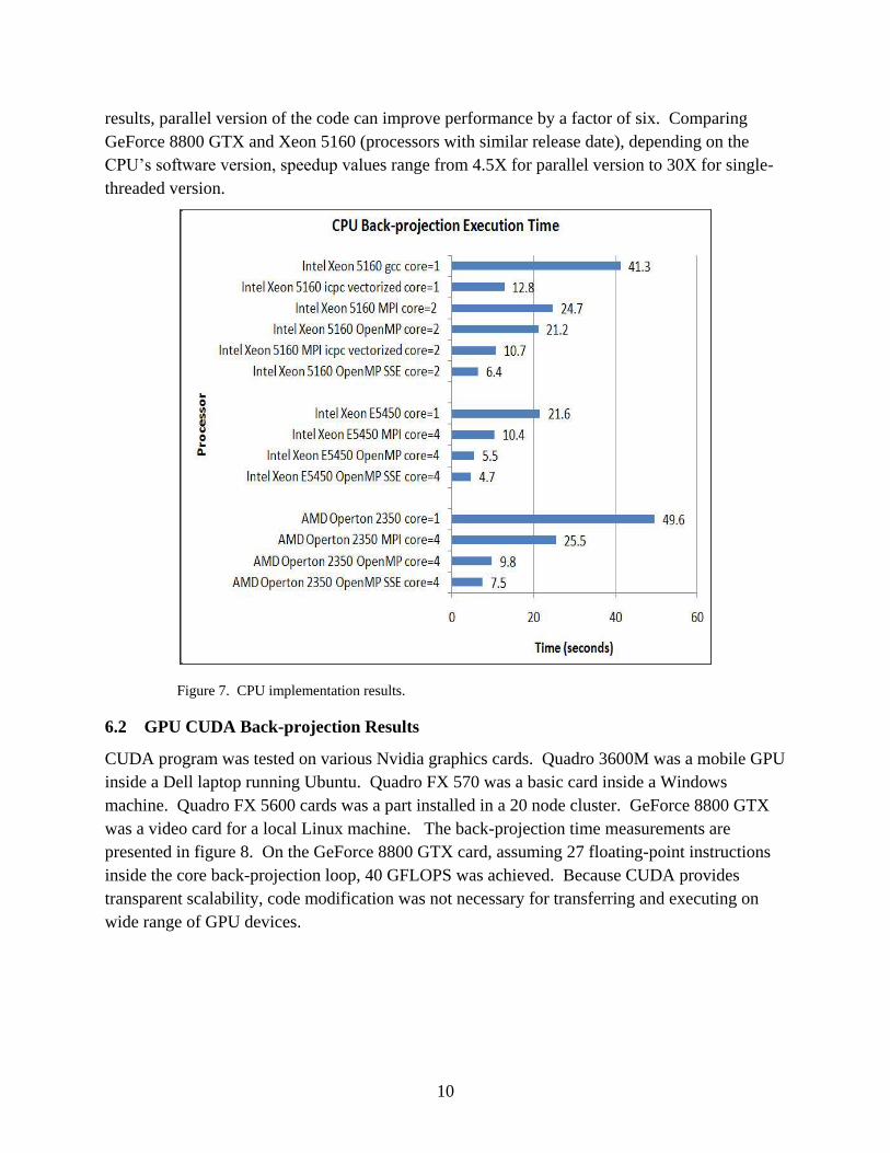
6.1 CPU Back-projection Results
For the CPU processors, OpenMP, MPI, and SSE executions had a great impact on performance
as shown in figure 7. OpenMP and MPI divide the code to run on multiple cores in parallel. The
use of SSE instructions enables 128-bit SIMD operations. As indicated by the CPU timing
10
results, parallel version of the code can improve performance by a factor of six. Comparing
GeForce 8800 GTX and Xeon 5160 (processors with similar release date), depending on the
CPU’s software version, speedup values range from 4.5X for parallel version to 30X for single-
threaded version.
Figure 7. CPU implementation results.
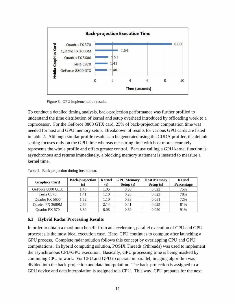
6.2 GPU CUDA Back-projection Results
CUDA program was tested on various Nvidia graphics cards. Quadro 3600M was a mobile GPU
inside a Dell laptop running Ubuntu. Quadro FX 570 was a basic card inside a Windows
machine. Quadro FX 5600 cards was a part installed in a 20 node cluster. GeForce 8800 GTX
was a video card for a local Linux machine. The back-projection time measurements are
presented in figure 8. On the GeForce 8800 GTX card, assuming 27 floating-point instructions
inside the core back-projection loop, 40 GFLOPS was achieved. Because CUDA provides
transparent scalability, code modification was not necessary for transferring and executing on
wide range of GPU devices.
11
Figure 8. GPU implementation results.
To conduct a detailed timing analysis, back-projection performance was further profiled to
understand the time distribution of kernel and setup overhead introduced by offloading work to a
coprocessor. For the GeForce 8800 GTX card, 25% of back-projection computation time was
needed for host and GPU memory setup. Breakdown of results for various GPU cards are listed
in table 2. Although similar profile results can be generated using the CUDA profiler, the default
setting focuses only on the GPU time whereas measuring time with host more accurately
represents the whole profile and offers greater control. Because calling a GPU kernel function is
asynchronous and returns immediately, a blocking memory statement is inserted to measure a
kernel time.
Table 2. Back-projection timing breakdown.
Graphics Card Back-projection
(s)
Kernel
(s)
GPU Memory
Setup (s)
Host Memory
Setup (s)
Kernel
Percentage
GeForce 8800 GTX 1.40 1.05 0.30 0.022 75%
Tesla C870 1.41 1.10 0.26 0.023 78%
Quadro FX 5600 1.52 1.10 0.33 0.051 72%
Quadro FX 3600M 2.64 2.14 0.41 0.025 81%
Quadro FX 570 8.80 8.08 0.69 0.020 91%
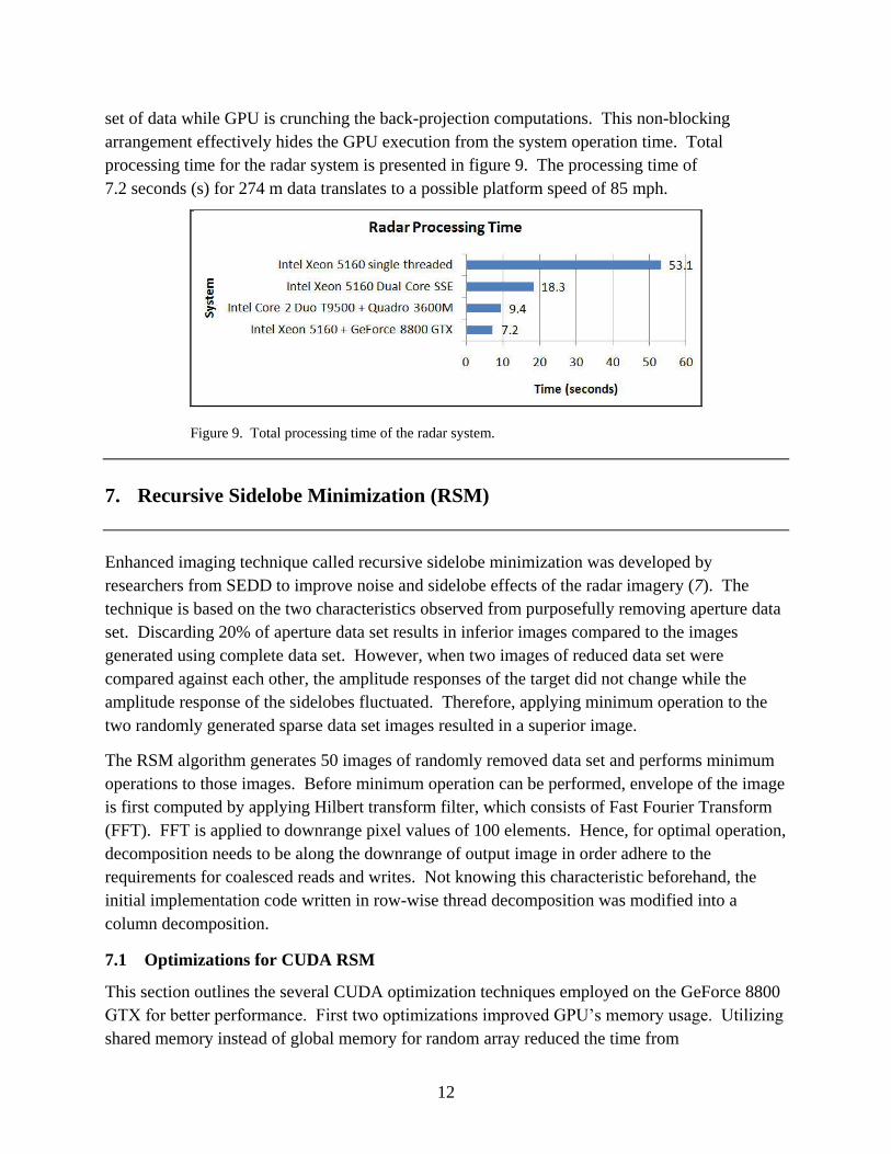
6.3 Hybrid Radar Processing Results
In order to obtain a maximum benefit from an accelerator, parallel execution of CPU and GPU
processes is the most ideal execution case. Here, CPU continues to compute after launching a
GPU process. Complete radar solution follows this concept by overlapping CPU and GPU
computations. In hybrid computing solution, POSIX Threads (Pthreads) was used to implement
the asynchronous CPU/GPU execution. Basically, GPU processing time is being masked by
continuing CPU to work. For CPU and GPU to operate in parallel, imaging algorithm was
divided into the back-projection and data interpolation. The back-projection is assigned to a
GPU device and data interpolation is assigned to a CPU. This way, CPU prepares for the next
12
set of data while GPU is crunching the back-projection computations. This non-blocking
arrangement effectively hides the GPU execution from the system operation time. Total
processing time for the radar system is presented in figure 9. The processing time of
7.2 seconds (s) for 274 m data translates to a possible platform speed of 85 mph.
Figure 9. Total processing time of the radar system.
7. Recursive Sidelobe Minimization (RSM)
Enhanced imaging technique called recursive sidelobe minimization was developed by
researchers from SEDD to improve noise and sidelobe effects of the radar imagery (7). The
technique is based on the two characteristics observed from purposefully removing aperture data
set. Discarding 20% of aperture data set results in inferior images compared to the images
generated using complete data set. However, when two images of reduced data set were
compared against each other, the amplitude responses of the target did not change while the
amplitude response of the sidelobes fluctuated. Therefore, applying minimum operation to the
two randomly generated sparse data set images resulted in a superior image.
The RSM algorithm generates 50 images of randomly removed data set and performs minimum
operations to those images. Before minimum operation can be performed, envelope of the image
is first computed by applying Hilbert transform filter, which consists of Fast Fourier Transform
(FFT). FFT is applied to downrange pixel values of 100 elements. Hence, for optimal operation,
decomposition needs to be along the downrange of output image in order adhere to the
requirements for coalesced reads and writes. Not knowing this characteristic beforehand, the
initial implementation code written in row-wise thread decomposition was modified into a
column decomposition.
7.1 Optimizations for CUDA RSM
This section outlines the several CUDA optimization techniques employed on the GeForce 8800
GTX for better performance. First two optimizations improved GPU’s memory usage. Utilizing
shared memory instead of global memory for random array reduced the time from
13
310 s to 108 s. Another optimization in relation to efficient memory usage was assigning more
threads per block in order to meet the divisible by 16 requirement for coalesced memory
operation. Instead of 100 elements in a column, 112 elements were assigned to align memory
accesses for the coalesce store, which improved the time by a factor of 1.4x. Third optimization
involved a traditional reducing workload in the compute intensive inner loop. Index value
lookup was pulled out of the main loop by storing the data signal values directly, which yielded a
1.8x speedup. Forth optimization reduced the total number of signal memory access by
subtracting from an original image. Rather than building up to an image using 80% of data, 20%
of data is removed from an original image, which resulted in less memory lookup. Next
optimization implemented a customized N2 complexity discrete Fourier transform (DFT)
algorithm where imaginary input and real output values were ignored. At first, the CUDA
version of DFT did not outperform the CPU’s FFT due to its small input size of 100 elements.
However, through splitting the kernel into forward and reverse DFT reduced register usage and
increased GPU’s occupancy. Although splitting kernel added extra memory operations, higher
occupancy improved overall performance. Sixth optimization involved distributing array
initialization work of transferring data from global to shared memory. Instead of assigning work
to one thread, the initialization step was divided among multiple threads. At this point, CUDA
profile showed 58% of compute time being spent inside the envelope function. To mitigate the
compute requirement of the envelope routine, fast math compiler flag was used to accelerate the
DFT computation. Fast math compiler flag computes higher level math functions in special
function units (SFU) at a modestly reduced precision. Updating CUDA driver also had a slight
improvement. After a variety of optimization techniques, final execution time was measured to
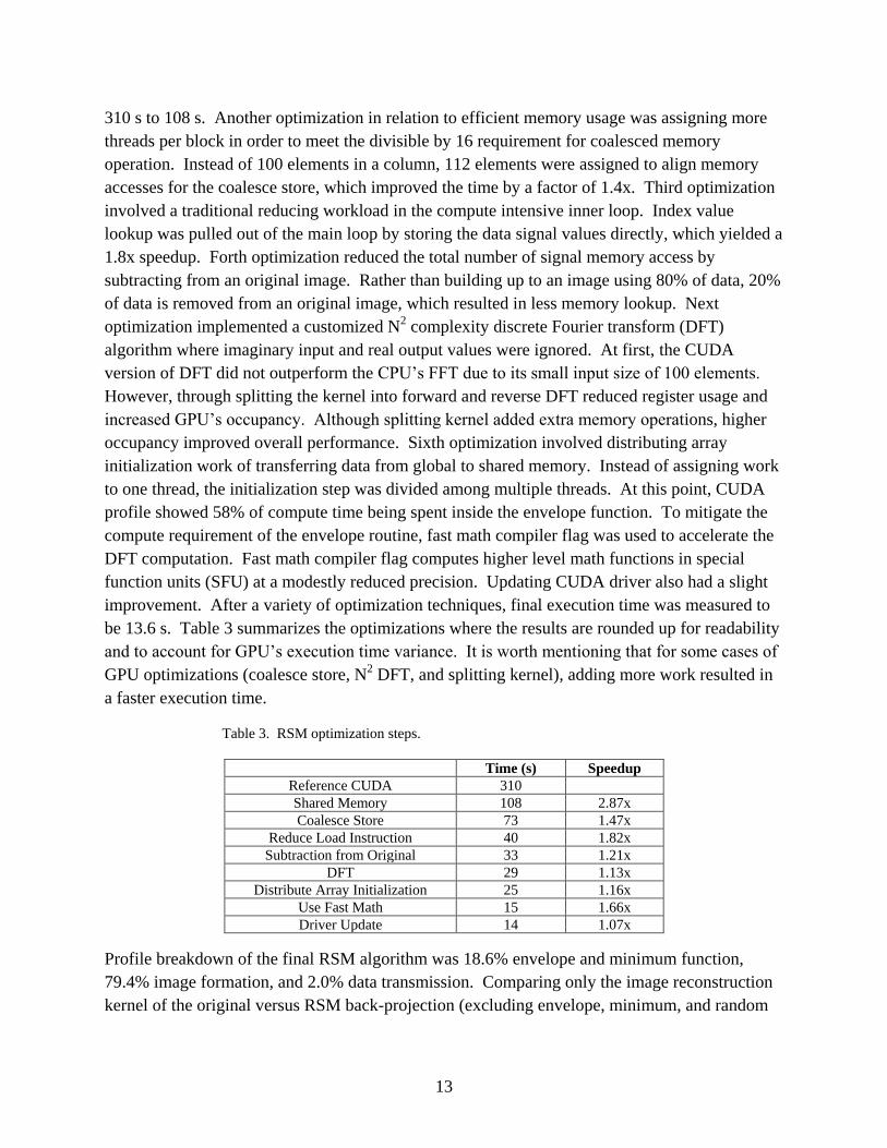
be 13.6 s. Table 3 summarizes the optimizations where the results are rounded up for readability
and to account for GPU’s execution time variance. It is worth mentioning that for some cases of
GPU optimizations (coalesce store, N2 DFT, and splitting kernel), adding more work resulted in
a faster execution time.
Table 3. RSM optimization steps.
Time (s) Speedup
Reference CUDA 310
Shared Memory 108 2.87x
Coalesce Store 73 1.47x
Reduce Load Instruction 40 1.82x
Subtraction from Original 33 1.21x
DFT 29 1.13x
Distribute Array Initialization 25 1.16x
Use Fast Math 15 1.66x
Driver Update 14 1.07x
Profile breakdown of the final RSM algorithm was 18.6% envelope and minimum function,
79.4% image formation, and 2.0% data transmission. Comparing only the image reconstruction
kernel of the original versus RSM back-projection (excluding envelope, minimum, and random
14
calculations), the execution time increased from 1.04–8.97 s. The effect of 10x memory
operation (50*20%) increase on a GPU resulted in the kernel execution time increase of 8.6x
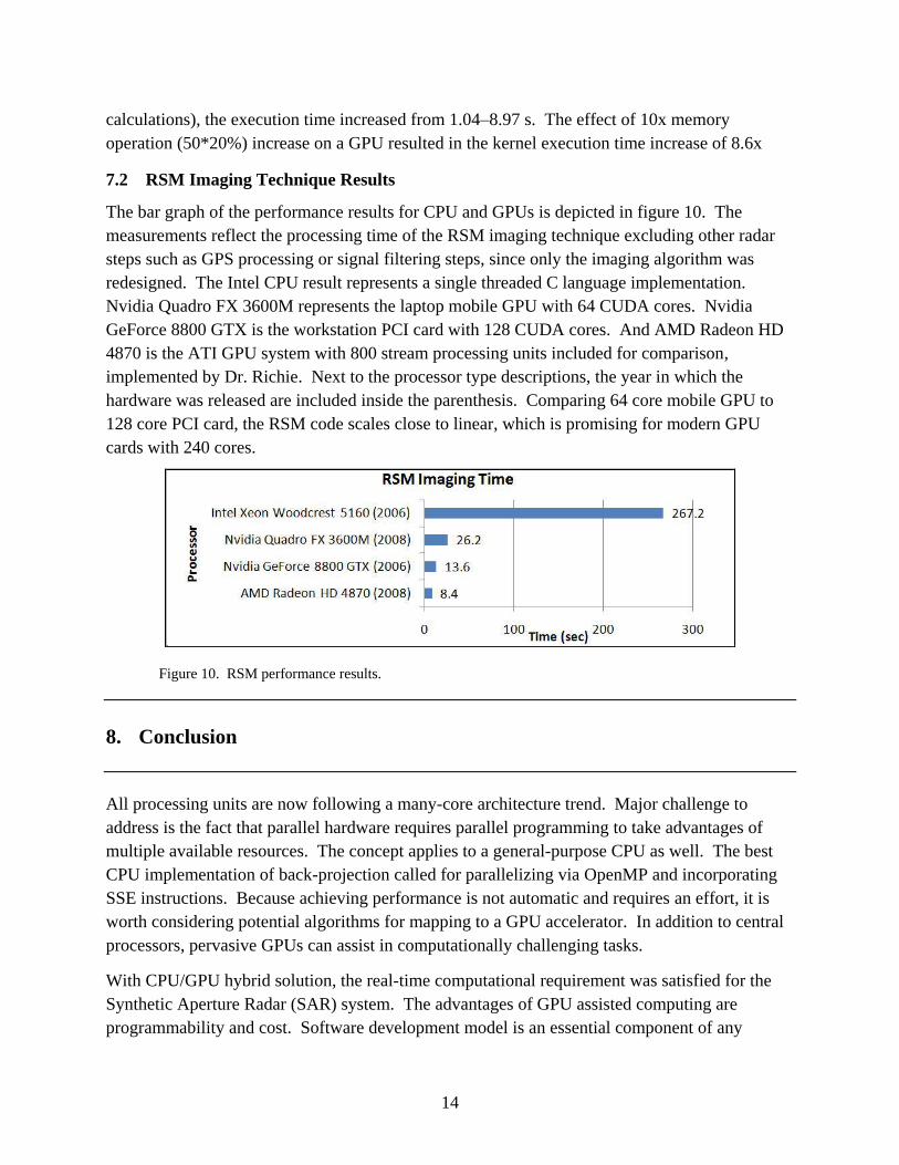
7.2 RSM Imaging Technique Results
The bar graph of the performance results for CPU and GPUs is depicted in figure 10. The
measurements reflect the processing time of the RSM imaging technique excluding other radar
steps such as GPS processing or signal filtering steps, since only the imaging algorithm was
redesigned. The Intel CPU result represents a single threaded C language implementation.
Nvidia Quadro FX 3600M represents the laptop mobile GPU with 64 CUDA cores. Nvidia
GeForce 8800 GTX is the workstation PCI card with 128 CUDA cores. And AMD Radeon HD
4870 is the ATI GPU system with 800 stream processing units included for comparison,
implemented by Dr. Richie. Next to the processor type descriptions, the year in which the
hardware was released are included inside the parenthesis. Comparing 64 core mobile GPU to
128 core PCI card, the RSM code scales close to linear, which is promising for modern GPU
cards with 240 cores.
Figure 10. RSM performance results.
8. Conclusion
All processing units are now following a many-core architecture trend. Major challenge to
address is the fact that parallel hardware requires parallel programming to take advantages of
multiple available resources. The concept applies to a general-purpose CPU as well. The best
CPU implementation of back-projection called for parallelizing via OpenMP and incorporating
SSE instructions. Because achieving performance is not automatic and requires an effort, it is
worth considering potential algorithms for mapping to a GPU accelerator. In addition to central
processors, pervasive GPUs can assist in computationally challenging tasks.
With CPU/GPU hybrid solution, the real-time computational requirement was satisfied for the
Synthetic Aperture Radar (SAR) system. The advantages of GPU assisted computing are
programmability and cost. Software development model is an essential component of any
15
processor technology. GPU programming model builds and extends to the popular C software,
hence keeping the changes and learning curve to a minimum. Once the concept of thread
parallelism is grasped, CUDA programming is not much more difficult than standard C.
Moreover, graphics cards are affordable and widely available commodity components. GPU
computing leverages a powerful chip with well established technology and gaming industry’s
support. As a result of these characteristics, GPU processors are expanding its applicable area
from desktop media applications to supercomputing.
16
9. References
1. Doweck, J. Inside Intel Core Microarchitecture. Intel Corporation, 2006.
2. Owens, J. D.; Houston, M.; Luebke, D.; Green, S.; Stone, J. E.; Phillips, J. C. GPU
Computing. Proceedings of the IEEE, Vol. 96, (5), May 2008.
3. Ressler, M.; Nguyen, L.; Koenig, F.; Wong, D.; Smith, G. The Army Resarch Laboratory
(ARL) Synchronous Impulse Reconstruction (SIRE) Forward-Looking Radar. Proceedings
of the SPIE. Unmanned Systems Technology IX. Vol. 6561, May 2007.
4. McCorkle, J. W.; Rofheard, M. An Order N^2log(N) Backprojector Algorithm for
Focusing Wide-angle Wide-bandwidth Arbitrary-motion Synthetic Aperture Radar. SPIE.
1996, Vol. 2747.
5. Nvidia CUDA, Compute Unified Device Architecture. Programming Guide. Nvidia
Corporation: Santa Clara, CA, 2008.
6. Fatahalian, K.; Houston, M. GPUs: A Closer Look. ACM Queue, Vol. 6, (2), 2008.
7. Nguyen, L. Signal and Image Processing Algorithms for the U.S. Army Research
Laboratory Ultra-wideband (UWB) Synchronous Impulse Reconstruction (SIRE) Radar.
ARL-TR-4784, U.S. Army Research Laboratory: Adelphi, MD, 2009.
17
List of Symbols, Abbreviations, and Acronyms
ALU arithmetic logic unit
AMD Advanced Micro Devices, Inc.
API application program interface
CPU Central Processing Unit
CUDA Compute Unified Device Architecture
DFT discrete Fourier transform
DoD Department of Defense
ENS/C4I Electronics, Networking, and Systems/Command, Control, Communications,
Computers, & Intelligence
FFT Fast Fourier Transform
GPU Graphics Processing Unit
HPCMO High Performance Computing Modernization Office
m meter
PCI peripheral component interconnect
PET Productivity Enhancement and Technology Transfer (ack)
RSM Recursive Sidelode Minimization
s second
SAR Synthetic Aperture Radar
SEDD Sensors and Electron Devices Directorate
SFU special function units
SIMD single instruction multiple data
SSE streaming SIMD extensions
NO. OF
COPIES ORGANIZATION
18
1 DEFENSE TECHNICAL
(PDF INFORMATION CTR
only) DTIC OCA
8725 JOHN J KINGMAN RD
STE 0944
FORT BELVOIR VA 22060-6218
1 DIRECTOR
US ARMY RESEARCH LAB
IMNE ALC HRR
2800 POWDER MILL RD
ADELPHI MD 20783-1197
1 DIRECTOR
US ARMY RESEARCH LAB
RDRL CIM L
2800 POWDER MILL RD
ADELPHI MD 20783-1197
1 DIRECTOR
US ARMY RESEARCH LAB
RDRL CIM P
2800 POWDER MILL RD
ADELPHI MD 20783-1197
ABERDEEN PROVING GROUND
1 DIR USARL
RDRL CIM G (BLDG 4600)
6 DIR USARL
RDRL CI
R NAMBURU
RDRL CIH
C NIETUBICZ
RDRL CIH C
J CLARKE
S PARK
D SHIRES
RDRL CIH M
P COLLINS