Embed Size (px)
Citation preview

We hit the gas
Central Gas Supply SystemsReinstgastechnik
Wir können mit Druck umgehenWir geben Gas
Zentrale Gaseversorgung
Zen
trale Gaseverso
rgu
ng
Rei
nst
gas
tech
nik
Vulkan_GasTech_Montiert mit 8mm Steg.indd 101.03.15 11:56
your way to our production in Solingen
for your navigation system
Please enter the following address:Stadt: Solingen
Straße: Erikaweg
Due to the fact that the other side of the “Bonner Straße” (street) at our company has
another name, Ohligser Straße (street), no actual navigation system is able to
find our number “305”.Close to our premises the “Erikaweg” exits
from the “Bonner Straße” (street). When your navigation systems tells you “please turn into the Erikaweg”,
you can see our company.
Your way to us
Exit Solingen (20)
Yo
ur
con
tact
per
son
s /
Yo
ur
way
to
us
The Vulkan Team is yours at any time
Management Rolf Everwand + 49 (0)212 / 88 09-15 [email protected]
Michael Everwand + 49 (0)212 / 88 09-27 [email protected]
Sales/Technique Manfred Biermann + 49 (0)212 / 88 09-26 [email protected]
Guido Fiebig + 49 (0)212 / 88 09-17 [email protected]
Sven Tetzlaff + 49 (0)212 / 88 09-30 [email protected]
Sales Margarete Bortz + 49 (0)212 / 88 09-23 [email protected]
Petra Quabus + 49 (0)212 / 88 09-24 [email protected]
Purchase Sabine Schulte-Meier + 49 (0)212 / 88 09-19 [email protected]
Shipping department Gerd Bülte + 49 (0)212 / 88 09-28 [email protected]
Accountancy Irena Hyza + 49 (0)212 / 88 09-22 [email protected]
Fax + 49 (0)212 / 88 09-10
© G
oogl
e M
aps

Imp
ress
um
3
IMPRESSUM
Responsible for the content:Everwand & Fell GmbHBonner Straße 305D-42697 Solingen
P.O. Box: 12 02 39D-42977 SolingenTelephone: +49 (0)212 / 88 09-0Fax: +49 (0)212 / 88 09-10E-Mail: [email protected]
Managing Directors: Rolf Everwand, Michael Everwand
Place of business: Solingen, Deutschlandregister court: Wuppertal, HRB 14988Vat number: DE 813264760
Photos: Manfred Biermann, Martin Leclaire, Helge Pohl, Cedric Schanze, Marcel Schauer - Fotolia.com Text and Project management: Aline Scholz, D-CologneDesign: Thomas Gebhard, Köln, Daniel Giesen, D-Cologne
Print: W+S Druck und Medien GmbH, D-Troisdorf-Spich
Bank details:National Bank AGbank code 360 200 30account no. 6728820BIC NBAG DE 3 EIBAN DE87 3602 0030 0006 7288 20
Sparkasse Langenfeldbank code 375 517 80account no. 33002197BIC WELADED1LAFIBAN DE16 3755 1780 0033 0021 97
Commerzbank AGbank code 342 400 50account no. 219 5162 00BIC COBADEFF342IBAN DE16 3424 0050 0219 5162 00
The Managing Directors accept no responsibility for changings and factual errors.Issue September 2017.

4
Co
nte
nt
Imprint, Bank Data ...................................................................................... Page 3
Everwand-group .......................................................................................... Page 5
TECLINEAutomatic manifolds Modula .................................................................. Page 12
Manual manifolds Modula Vareo ............................................................ Page 16
Rail systems Modula Vareo ..................................................................... Page 19
Single cylinder- and Single bundle manifold Modula ........................ Page 21
Cylinder and bundle hoses Vareo .......................................................... Page 24
Cylinder and bundle hoses standard .................................................... Page 25
Cylinder and bundle hoses standard and Vareo ................................. Page 26
Tapping point Vulkan ................................................................................ Page 27
Manifold regulators Vulkan acc. to ISO 7291 ....................................... Page 30
In-line regulator Vulkan ........................................................................... Page 37
Pressure regulator Vulkan acc. to ISO 2503 ........................................ Page 43
Accessories ................................................................................................ Page 48
Accessories - Tube fittings and flashback arrestors ........................ Page 54
Accessories for regulators and Spare part sets Vulkan .................... Page 55
Spare part sets Vulkan ............................................................................ Page 56
Accessories for regulators ...................................................................... Page 58
Flow charts ................................................................................................. Page 59
LABLINEAutomatic manifolds Modula .................................................................. Page 62
Manual manifolds Modula Vareo ............................................................ Page 63
Rail systems Vareo / Single cylinder manifolds Vareo ...................... Page 64
Cylinder and bundle hoses Vulkan ......................................................... Page 65
Tapping point Vulkan ................................................................................ Page 66
In-line regulator Vulkan ........................................................................... Page 67
Pressure regulator Vulkan acc. to ISO 2503 ........................................ Page 68
Accessories Vulkan LabLine ................................................................... Page 71
Spare part sets for regulators and manifolds ................................... Page 73
Flow charts ............................................................................................... Page 74
CONTENT

Since many years the Everwand-group is a well-known part of the gas industry. From single components to complete solutions or services for technical or medical gases as well as for high purity gases, piping constructions and automated welding
or brazing machines – Everwand has a wide product range and supplies global players around the world.
As a family owned company looking back on more than 100 years of history, Everwandbenefi ts from its large wealth of experience and combines that with modern and innovativeconcepts.
„The subject‚ gas‘ was omnipresent at home and it is always fascinating.I was particularly interested in bringing new ideas into our company aftermy studies.“ (Michael Everwand)
The brand name ‚Vulkan‘ made by Everwand, stands for conscientious precision work continual further development and state of the technology.
Also our online shop is constantly updated. www.gasetechnik24.de contains all important information about the Vulkan products. Ordering online you will benefi t from attractive prices and special offers. This service is „open“ 24 hours a day, enabling you to browse and order where ever and when ever you want.
Responsible for the online-shop: Ingo Knautz, gasetechnik24 KG, Rechenweg 16, 42655 Solingen
5
Eve
rwan
d
gasetechnik24
YEARSJAHRE100>INNOVATION
TRADITION
everwand.de
FRESH IDEAS MEET 100 YEARS OF EXPERIENCE

TECHNICAL PROGRESS WITH THE VIEW TO OUR ENVIRONMENT
Some major facts in briefFoundation: 1911
Number of employees: 60
Management: Rolf Everwand and
Michael Everwand
Product range: Single components,
regulators, manifolds, individual
complete solutions for central gas
manifolds for technical and medical
gases, plant and pipeline engineering
and construction, special purpose
welding and brazing machines
Certification: Certified acc. to the
Pressure Equipment Directive 2014/68/EU
Memberships: DVS, VDMA, standard
committee „Welding“ DIN, supporting group
standard committee „Welding“ DIN DIN,
DVS (in association „brazing“)
Quality: consistently in-house
quality management
Nowadays everybody is talking about environmental protection and sustainability. Since many years the Everwand group committed itself to highest quality and safety standards at its own production. That also requests a most possible
sustainable manufacturing and the utilisation of recyclable materials. The use of state-of-the-art hardware minimizes the energy input, creates the production more efficient and environmentally compliant.
„Today the environment concerns everyone, but especially enterprises bear a huge responsibility. Since many years we pay attention to a sustainable and preserving production!“ (Michael Everwand)
All products are Made in Germany and all vendor parts are made in the EU not to guarantee only a maximum quality, but also to reduce the CO
2 emission and to preserve
our environment.
„The label „Made in Germany“ fully applies to our products, as we only manufacture in Germany.“ (Rolf Everwand)
Everwand: Expertise, progress, sustainability around „gas“.
6
Eve
rwan
d

7
Eve
rwan
d
EVEN IF VULKAN DOESN’T STAND ON THE COVER, VULKAN MIGHT BE INSIDE!
Today you can find Vulkan quality also there where you do not expect it. Since many years the Everwand-group is an OEM (Original Equipment Manufacturer) for many well-known companies of Vulkan-products, which they distribute under their own
labels. Our aim is to continue partnership with the best, by providing top-quality products and service. We supply to the following industries:
• Gas industry• Medical industry• Automotive industry• Heat exchanger industry• Glass industry, food industry, Laboratory- and high purity technology• Steel and Ship building industry

CUSTOM MADE – YOU CAN ALWAYS FIND THE PERFECT SOLUTION
The Vulkan catalogue shows a variety of different components for the central gas supply. However, the needs and the requirements of our customers and the variety of applications are beginning to differ more and more. 40 years ago the Everwand
Group already began to design and deliver individual customized systems.
„From experience we learned: There is always a perfect solution and we love to rack our brains until we find this solution.“ (Michael Everwand)
Everwand is a full-service provider, supplying the entire range from a single source. Planning, design engineering, assembly as well as maintenance, always in a top quality and with fair conditions. Let us convince you from our comprehensive range of services. Our competent team will advise and support you in all issues regarding your application.
8
Eve
rwan
d

CUSTOM MADE – YOU CAN ALWAYS FIND THE PERFECT SOLUTION
9
Eve
rwan
d
EVERWAND DRUCKGASTECHNIK GMBH – HOSES AND MORE
VULKAN-BRAZING TECHNOLOGY – BRAZING MACHINES MADE IN SOLINGEN ARE OPERATING ALL OVER THE WORLD
Since acquiring the Hummel Engineering Products GmbH in 2002, the Everwand-group produces in Solingen/Germany high-quality hose systems for high and low pressure, technical- and cryogenic gases. Furthermore, a core competence of the company lies
in developing special solutions tailored to suit individual customer needs. Maximum opera- tional reliability is our supreme goal. Each product undergoes a strict in-house quality control procedure, and only passes this if it complies with the high quality criteria we set for Vulkan products.
What do fluid components for automotive applications, HVAC components, solar coll-ectors, steel pipe furnitures, domestic appliances, sanitary fittings, or carbide tools have in common? Automated brazing is typically required to
manufacture such components and Vulkan Brazing Machines are often used to perform that work. For more than 25 years, the Everwand brazing specialists have been providing now solutions for the automation of brazing processes. Solutions, that are speci-fically tailored to the individual needs of our customers. Right from the project start with first advisory discussions and demand analy-sis up to the installation and commissioning of the machine, in all phases of a project we maintain in a close dialogue with our clients. Thus, customized brazing machines are created, that meet all the high standards set by the industry.
10
Eve
rwan
d
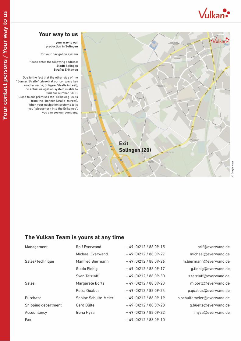
CENTRAL GAS SUPPLY 4.0 – GAS MONITORING FOR THE INDUSTRY 4.0
The uninterrupted and frictionless operation of your production becomes more and more important. A blackout means unexpected costs. Shutdown periods cause delayed delivery times and so upset customers. Consequently it is absolutely necessary to monitor not only machines and technical equipment, but also the gas
supply. Only a permanent and failure-free supply for your production with gas guarantees a high quality finishing of your products and ensures hence the satisfaction of your customers.
Welcome to the gas supply 4.0
The modern Vulkan Gas monitoring systems monitor permanently all necessary operation pressure and indicate immediately any deviation and interruption, which can be solved instantaneously. If needed, every single incoming gas cylinder can be scanned and registered, to even avoid a wrong connection to the gas supply system.
In addition to this you can display all operation conditions on the GasMoApp on your tablet (iPad). So you have access to all of your operating data of your gas supply system at any time all over the world.
The Gasmonitoring APP
The Gasmonitoring App is able to indicate you any operation condition of your gas supply system on your IOS iPad, and to generate any indications and reports of actual changings or disruptions. All data of the transducers and sensors will be transfered by a small control cabinet via WLAN or GSM to an external server (cloud). The App in combination with your iPad (on iPhone actually not available) can receive and show these data.
• displays clearly gas cylinder pressures• shows the different gas types and concentrations• the actual state of the supply is disposable• for every gas line status and alarm messages can indicated• multi storage management is possible• identification of supply stocks and possible shortages

11
VULKAN TECLINEFOR TECHNICALGASES
TECLINE
Vu
lkan
Tec
Lin
e

Lab
Lin
e V
ulk
an
12
TECLINEA
uto
mat
ic m
anif
old
s M
od
ula
Automatic manifold Modula AM 35/300 Kfor oxygen and other gases except acetylene Modula add on system, can be expanded to your requirements consisting of:2 Manifold regulators H 20 acc. to ISO 7291, adiabatic compression tested 1 In-line regulator AD 351 Automatic change over block1 Main shut off valve2 contact gauges with Reed switch (optional) acc. to DIN EN 837-1
complete on stainless steel base plate
Automatic manifold ModulaAt the fully automatic change-over device, the working pressure is adjusted through the pressure regulator. The switch from the empty to the full side will occur here automatically with the help of the change-over block which is installed between the two main pressure regulators. It is important that both manifold regulators are adjusted to the same working pressure. This is done by the manufacturer. If the cylinders or bundles on one side are empty, the pressure of the cylinders is reduced, leading to a reduction of the working pressure of the manifold regulator adjacent to the change-over block. If the working pressure of the main pressure regulator drops by more than 3-4/5-7 bar below the programmed pressure, the tension of the spring inside of the change-over block will cause the piston to move to the full side. If the empty cylinders or bundles are replaced, they must be opened again, so that the full pressure comes up to the automatic change-over device. This does not cause another switch of the change-over block. The switch will occur only at the time when the side currently in use is empty
Technical data Flow chart see enclosureBody brass pe max 300 bar pa 0-10 barSeals EPDM, polyamide, Viton, PTFE Qmax 50 Nm³/h at pa 10 barDiaphragm PTFE de M 24x1,5 RH da G 3/8x10 mmLeakage rate 1x10⁻⁶mbar l/s B 450 mm H 420 mmTemperaturee -20 to +60 °C T 210 mm M 11,0 kg
12
gas type article-no. with contact gauge article-no. without contact gauge Oxygen 414 851 413 850nitrogen 414 351 413 350argon 414 651 413 650 CO2 414 651 06 413 650 06helium 414 651 26 413 650 26hydrogen 414 451 413 450compressed air 414 751 413 750
Automatic manifold Modula AM 35/300 Has AM 35 KH, but without In-line regulator, working pressure pre-adjusted at 20 bar
Technical data Flow chart see enclosureBody brass pe max 300 bar pa 20 barSeals EPDM, polyamide, Viton, PTFE Qmax 120 Nm3/h at pa 20 barDiaphragm PTFE de M 24x1,5 RH da G 3/4x18 mmLeakage rate 1x10⁻⁶mbar l/s B 450 mm H 340 mmTemperature -20 to +60 °C T 210 mm M 9,0 kg
gas type Article-no. with contact gauge Article-no. without contact gauge Oxygen 414 854 413 853nitrogen 414 354 413 353argon 414 654 413 653 CO2 414 654 06 413 653 06helium 414 654 26 413 653 26hydrogen 414 454 413 453compressed air 414 754 413 753
Lab
Lin
e V
ulk
an
13
TECLINE
Au
tom
atic
man
ifo
lds
Mo
du
la
13
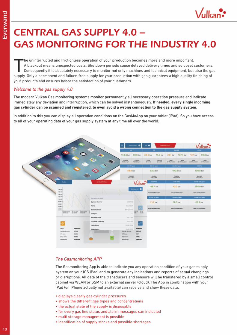
Automatic manifold Modula AM 45/300 Kfor oxygen and other gases except acetylene Modula add on system, can be expanded to your requirements consisting of:2 Manifold fin regulators HR 20 acc. to ISO 7291, BAM approved pre-adjusted 1 Automatic change over block1 Main shut off valve2 contact gauge acc. to DIN EN 837-1 optional with Reed switch,
complete on stainless steel base plate
Technical data Flow chart see enclosureBody brass pe max 300 bar pa 20 barSeals EPDM, polyamide, Viton Qmax 170 Nm3/h at pa 20 barDiaphragm PTFE de M 24x1,5 RH da G 3/4x18 mmLeakage rate 1x10⁻⁶mbar l/s B 500 mm H 370 mmTemperature -20 to +60 °C T 230 mm M 12,5 kg
gas type Article-no. with contact gauge Article-no. without contact gauge oxygen 414 856 413 855nitrogen 414 356 413 355argon 414 656 413 655CO2 414 656 06 413 655 06helium 414 656 26 413 655 26hydrogen 414 456 413 455compressed air 414 756 413 755
Automatic manifold Modula AM 55/300 Kfor oxygen and other gases except acetylene Modula add on system, can be expanded to your requirements consisting of:2 Manifold fin regulators HR 40 acc. to ISO 7192, adiabatic compression tested,
O2 with metal diaphragm
1 Automatic change over block1 Main shut off valve2 contact gauge acc. to DIN EN 837-1 optional with Reed switch,
complete on stainless steel base plate
Technical data Flow chart see enclosureBody brass pe max 300 bar pa 28 barSeals EPDM, polyamide, Viton Qmax 250 Nm3/h at pa 28 barDiaphragm rubber; with O2: V2A de M 24x1,5 RH da G 3/4x18 mmLeakage rate 1x10⁻⁶mbar l/s B 500 mm H 380 mmTemperature -20 to +60 °C T 230 mm M 15,0 kg
gas type Article-no. with contact gauge Article-no. without contact gauge oxygen 414 858 413 859nitrogen 414 358 413 359argon 414 658 413 659CO2 414 658 06 413 659 06helium 414 658 26 413 659 26hydrogen 414 458 413 459compressed air 414 758 413 759
Automatic Manifold AM 40/300as AM 35/300 H, but with working pressure pre-adjusted at 40 bar
Technical data Flow chart see enclosureBody brass pe max 300 bar pa 40 barSeals EPDM, polyamide, Viton, PTFE Qmax 160 Nm3/h at pa 40 barDiaphragm PTFE de M 24x1,5 RH da G 3/4x18 mmLeakage rate 1x10⁻⁶mbar l/s B 530 mm H 400 mmTemperature -20 to +60 °C T 210 mm M 9,5 kg
gas type Article-no. with contact gauge Article-no. without contact gauge nitrogen 414 341 413 342argon 414 641 413 642CO2 414 641 06 413 653 06 helium 414 641 26 413 653 26hydrogen 414 441 413 442compressed air 414 741 413 742

14
Au
tom
atic
man
ifo
lds
Mo
du
la TECLINE
Automatic manifold Modula AM 35/300 KHMfor oxygen, inert gases and fuel gases except acetylene Modula add on system, can be expanded to your requirements as AM 35/300 KM, but without In-line regulator working pressure pre-adjusted at 20 bar
Technical data Flow chart see enclosureBody brass pe max 300 bar pa 20 barSeals EPDM, polyamide, Viton Qmax 120 Nm3/h at pa 20 barDiaphragm PTFE de M 24x1,5 RH da G 3/4x18 mmLeakage rate 1x10⁻⁶mbar l/s B 690 mm H 350 mmTemperature -20 to +60 °C T 210 mm M 11,0 kg
gas type article-no.oxygen 424 854nitrogen 424 354argon 424 654CO2 424 654 06helium 424 654 26hydrogen 424 454compressed air 424 754
Automatic manifold Modula AM 40/300 KMfor inert gases and fuel gases except acetylene Modula add on system, can be expanded to your requirements consisting of:2 Manifold regulators H 40 acc. to ISO 7291, adiabatic compression tested1 double non return valve,1 Main shut off valve2 solenoid valves 24V AC, normally closed 2 contact gauge acc. to DIN EN 837-1 with Reed switch,
complete on stainless steel base plate
Technical data Flow chart see enclosureBody brass pe max 300 bar pa 40 barSeals EPDM, polyamide, Viton Qmax 160 Nm3/h at pa 40 barDiaphragm PTFE de M 24x1,5 RH da G 3/4x18 mmLeakage rate 1x10⁻⁶mbar l/s B 690 mm H 350 mmTemperature -20 to +60 °C T 210 mm M 11,0 kg
gas type article-no.oxygen 25 bar working pressure 424 842nitrogen 424 342argon 424 642CO2 424 642 06helium 424 642 26hydrogen 424 442compressed air 424 742
Automatic manifold Modula AM 35/300 KMfor oxygen and other gases except acetylene Modula add on system, can be expanded to your requirements with solenoid valves for more precise switching processes and lower difference pressures between left and right side consisting of:2 Manifold regulators H 20 acc. to ISO 7291, adiabatic compression tested1 In-line regulator AD 351 double non return valve,1 Main shut off valve2 solenoid valves 24V AC, normally closed2 contact gauge acc. to DIN EN 837-1 with Reed switch,
complete on stainless steel base plate
Technical data Flow chart see enclosureBody brass pe max 300 bar pa 0-10 barSeals EPDM, polyamide, Viton Qmax 50 Nm3/h at pa 10 barDiaphragm PTFE de M 24x1,5 RH da G 3/8x10 mmLeakage rate 1x10⁻⁶mbar l/s B 690 mm H 430 mmTemperature -20 to +60 °C T 210 mm M 12,5 kg
gas type article-no.oxygen 424 851nitrogen 424 351argon 424 651CO2 424 651 06helium 424 651 26hydrogen 424 451compressed air 424 751

15
Au
tom
atic
man
ifo
lds
Mo
du
laTECLINEAutomatic manifold Modula AM 45/300 KMfor oxygen and other gases except acetylene Modula add on system, can be expanded to your requirements consisting of:2 Manifold fin regulators HR 20 acc. to ISO 7291, adiabatic compression tested1 double non return valve,1 Main shut off valve2 solenoid valves 24V AC, normally closed2 contact gauge acc. to DIN EN 837-1 with Reed switch,
complete on stainless steel base plate
Technical data Flow chart see enclosureBody brass pe max 300 bar pa 20 barSeals EPDM, polyamide, Viton Qmax 170 Nm3/h at pa 20 barDiaphragm rubber de M 24x1,5 RH da G 3/4x18 mmLeakage rate 1x10⁻⁶mbar l/s B 720 mm H 385 mmTemperature -20 to +60 °C T 210 mm M 13,0 kg
gas type article-no.oxygen 424 856nitrogen 424 356argon 424 656CO2 424 656 06helium 424 656 26hydrogen 424 456Compressed air 424 756

16
Man
ual
man
ifo
lds
Mo
du
la V
areo TECLINE
Base station Modula Vareo BS 60/300consisting of one distributing block Vareo with two inlets for 2x1 cylinder or 2x1 bundle or for the connection of further distributing blocks Vareo, 1 Manifold regulator H 20 acc. to ISO 7291, adiabatic compression tested1 Main shut off valvecomplete on stainless steel base plate
also with incorporated gas pre-heater GPH 200 available
also with incorporated gas pre-heater GPH 200 available
Technical data Flow chart see enclosureBody brass pe max 300 bar pa 0 - 20 barSeals EPDM, polyamide, Viton Q max 75 Nm³/h at pa 20 barDiaphragm PTFE de M 24x1,5 RH da G3/4x18 mmLeakage rate 1x10⁻⁶mbar l/s B 570 mm H 250 mmTemperature -20 to +60 °C T 210 mm M 10,0 kg
gas type article-no.oxygen 414 820nitrogen 414 320argon 414 620CO2 414 620 06helium 414 620 26hydrogen 414 420compressed air 414 720
Base station Modula Vareo BS 80/300as Modula Vareo BS 60, but with manifold fin regulator HR 20
Technical data Flow chart see enclosureBody brass pe max 300 bar pa 0-20 barSeals EPDM, polyamide, Viton Q max 170 Nm3/h at pa 20 barDiaphragm rubber de M 24x1,5 RH da G 3/4x18 mmLeakage rate 1x10⁻⁶mbar l/s B 590 mm H 250 mmTemperature -20 to +60 °C T 210 mm M 11,0 kg
gas type article-no.oxygen 414 825nitrogen 414 325argon 414 625CO2 414 625 06helium 414 625 26hydrogen 414 425compressed air 414 725
Manual manifold Modula Vareo 300 barModula add-on system, for cylinders- and bundles, flexible and always expandable. The heart of this system is the distributing block Modula Vareo which consists of 2 inlets for 2 cylinders or bundles and 2 outlets to connecting a manifold regulator or further distributing blocks Modula Vareo.The distributing block Modula Vareo contains the following components:2 shut off valves to shut off the cylinders or bundles,2 non return valves prevent the reverse flow of the gas into empty cylinders or bundles,2 sinter metal filters prevent the penetration of dirt and extendthe life cycle of
the complete manifold.Optionally: 2 purge valvesYour advantages of Modula Vareo:- compact construction - all functions in one block- modular system - always expandable- easy assembly - only few thread connections- easy maintenance - all components are easily exchangeable- individual - for 300 bar or 200 barThese components are available:Base station BSOne distributing block Modula Vareo with manifold regulator and shut off valvecompletely fixed. For 2 x 1 cylinders or 2 x 1 bundles or for the connection of furthermanifold stations VS to connect more cylinders or bundles.Manifold station VSReplaces the traditional rail system. To connect to other manifold systems or to connect to a base station.

17
Man
ual
man
ifo
lds
Mo
du
la V
areoTECLINE
Base station Modula Vareo BS 100/300as Modula Vareo BS 60, but with Manifold fin regulator HR 40
Base station Modula Vareo BS 120/300as Modula Vareo BS 60, but with Manifold fin regulator HR 60
Base station Modula Vareo BS 200/300as Modula Vareo BS 60, but with Manifold regulator LHR 300/200
Technical data Flow chart see enclosureBody brass pe max 300 bar pa 15-40 barSeals EPDM, polyamide, Viton Qmax 290 Nm³/h at pa 40 barDiaphragm rubber; with O2: V2A de M 24x1,5 RH da G 3/4x18 mmLeakage rate 1x10⁻⁶mbar l/s B 590 mm H 270 mmTemperature -20 to +60 °C T 210 mm M 14,0 kg
Technical data Flow chart see enclosureBody brass pe max 300 bar pa 15-60 barSeals EPDM, polyamide, Viton Qmax 450 Nm3/h at pa 60 barDiaphragm rubber; with O2: V2A de M 24x1,5 RH da G 3/4x18 mmLeakage rate 1x10⁻⁶mbar l/s B 590 mm H 270 mmTemperature -20 to +60 °C T 210 mm M 14,0 kg
Technical data Flow chart see enclosureBody brass pe max 300 bar pa 15-200 barSeals EPDM, PCTFE Qmax 480 Nm3/h at pa 200 barDiaphragm brass de M 24x1,5 RH da G 1/2 RhiLeakage rate 1x10⁻⁶mbar l/s B 590 mm H 330 mmTemperature -20 to +60 °C T 285 mm M 12,0 kg
gas type article-no.oxygen 414 840nitrogen 414 340argon 414 640CO2 414 640 06helium 414 640 26hydrogen 414 440compressed air 414 740
gas type article-no.oxygen 414 860nitrogen 414 360argon 414 660CO2 414 660 06helium 414 660 26hydrogen 414 460compressed air 414 760
gas type article-no.oxygen Flow direction from right to left 414 880nitrogen 414 380argon 414 680helium 414 680 26hydrogen 414 480compressed air 414 780
Base station Modula Vareo BS 270/300as BS 200/300 but with working pressure up to 270 bar
Technical data Flow chart see enclosureBody brass pe max 300 bar pa 15-270 barSeals EPDM, PCTFE Q max 480 Nm3/h at pa 200 barDiaphragm brass de M 24x1,5 RH da G 1/2 RhiLeakage rate 1x10⁻⁶mbar l/s B 590 mm H 330 mmTemperature -20 to +60 °C T 285 mm M 12,0 kg
gas type article-no.oxygen Flow direction from right to left 414 881nitrogen 414 381argon 414 681CO2 414 681 07helium 414 681 27hydrogen 414 481compressed air 414 781

Man
ual
man
ifo
lds
Mo
du
la V
areo TECLINE
Purge valve Vareoto fit into manifold station or base station Modula Vareo, complete with shut off valve and optionally with clamp ring outlet Ø 10 mm, for connection of a purging pipe system
type article-no.without clamp ring in outlet 414 038with clamp ring in outlet 414 037to connect to outlet of Vareo VS 414 039 05
Base station Modula Vareo BSA 10 Bfor acetylene for 2x1 bundles, acc. to ISO 14114 as Modula Vareo BSA 10F, but complete with Automatic Quick cut off valve for bundles
gas type article-no.acetylene 414 915
Technical data Flow chart see enclosureBody brass pe max 26 bar pa 0 - 1,5 barSeals EPDM, polyamide, Viton Qmax 10 Nm³/h at pa 1,5 barDiaphragm EPDM de W21,8x1/14LH da G 3/4x18 mmLeakage rate 1x10⁻⁶mbar l/s B 850 mm H 250 mmTemperature -20 to +60 °C T 210 mm M 15,0 kg
Base station Modula Vareo BSA 20 Bfor acetylene for 2x1 bundle, acc. to ISO 14114 as Modula Vareo BSA 10 B, but with Manifold regulator H 20 acetylene, flow 18 Nm3/h
gas type article-no.acetylene 414 920
Technical data Flow chart see enclosureBody brass pe max 26 bar pa 0 - 1,5 barSeals EPDM, polyamide, Viton Qmax 18 Nm³/h at pa 1,5 barDiaphragm EPDM de W21,8x1/14LH da G 3/4x18 mmLeakage rate 1x10⁻⁶mbar l/s B 980 mm H 250 mmTemperature -20 to +60 °C T 230 mm M 19,0 kg
Base station Modula Vareo BSA 40 Bfor Acetylen, for 2x1 Bundle, acc. to ISO 14114, as BSA 20 B, but with manifold regulator H 40 acetylene, flow 38 Nm³/h
gas type article-no.acetylene 414 940
Technical data Flow chart see enclosureBody brass pe max 26 bar pa 0 - 1,5 barSeals EPDM, polyamide, Viton Qmax 38 Nm³/h at pa 1,5 barDiaphragm EPDM de W21,8x1/14LH da G 3/4x18 mmLeakage rate 1x10⁻⁶mbar l/s B 980 mm H 275 mmTemperature -20 to +60 °C T 210 mm M 26,0 kg
18
Base station Modula Vareo BSA 10 Ffor acetylene for 2x1 cylinder acc. to ISO 14114, consisting of one distributing block Vareo with two inlets for 2x1 cylinder or for connection of further distributing blocks Vareo Vareo 1 Manual Quick cut off valve acc. to ISO 15615, 1 Flashback arrestor acc. to EN 730 and ISO 15615, and Manifold regulator HA10 acc. to ISO 7291 complete on stainless steel base plate
Technical data Flow chart see enclosureBody brass pe max 26 bar pa 0-1,5 barSeals EPDM, polyamide, Viton Qmax 10 Nm3/h at pa 1,5 barDiaphragm PTFE de W21,8x1/14 LH da G 3/4x18 mmLeakage rate 1x10⁻⁶mbar l/s B 860 mm H 250 mmTemperature -20 to +60 °C T 210 mm M 14,5 kg
gas type article-no.acetylene 414 910

Rai
l sys
tem
s M
od
ula
Var
eoTECLINEManifold stations Modula VareoThe manifold stations Modula Vareo replace the classic rail systems.One manifold station is designed for the connection of two cylinders or twobundles. It can be connected to one base station and one other manifold stationor with two other manifold stations.The manifold stations consists of two sinter filters, two non return valves andtwo shut off valves. Optionally every inlet can be equipped with a purge valve,including the possibility to connect a purging pipe system.
Manifold station Modula Vareo VSas rail system with two inlets for two cylinders or two bundles and connection tobase stations Modula Vareo BS or to further manifold stations
Manifold station Modula Vareo VSDas Manifold stations VS but without non return valve and sintered filter
Manifold station Modula Vareo VSLas Manifold stations VS but without shut off valve
type article-no.for oxygen, inert gases, fuel gases except acetylene 414 515for acetylene inlet W21,8x1/14LH 414 525
type article-no.for oxygen, inert gases, fuel gases except acetylene 414 505
type article-no.for oxygen, inert gases, fuel gases except acetylene 414 510
Technical data Flow chart see enclosureBody brass p max 300 bar Seals FKM (Viton), EPDM de M24x1,5RH da M24x1,5 RHLeakage rate 1x10⁻⁶mbar l/s B 190 mm H 190 mmTemperature -20 to +60 °C T 235 mm M 5,0 kg
19
Railsystem Vulkan VareoFor all gases excpet acetylene, inlets M24x1,5RHak with non return valve and filter, connection to manifold, M24x1,5RHk nut
quantity inlets left side article-no. right side article-no.1 424 515 01 424 515 212 424 515 02 424 515 223 424 515 03 424 515 234 424 515 04 424 515 245 424 515 05 424 515 256 424 515 06 424 515 26
Technical data Material brass/copper Pmax 300 bar Seals EPDM de M24x1,5RHak da M24x1,5RHnutLeakage rate 1x10⁻⁶mbar l/s Temperature -20 to +60 °C

Rai
l sys
tem
s M
od
ula
Var
eo TECLINEConnecting pipes Vareo DN 10to connect manifold station to base station or toautomatic manifolds Modula as well as manifold stations to each other
type article-no.for oxygen, inert gases, fuel gases except acetylene 414 560for acetylene 414 590
type article-no.for oxygen, inert gases, fuel gases except acetylene 414 562for acetylene 414 592
type article-no.
type article-no.
for oxygen, inert gases, fuel gases except acetylene 414 564for acetylene 414 594
for oxygen, inert gases, fuel gases except acetylene 414 561for acetylene 414 591
type article-no.for oxygen, inert gases, fuel gases except acetylene 414 566for acetylene 414 596
type article-no.for oxygen, inert gases, fuel gases except acetylene 414 568for acetylene 414 598
connecting pipe VB, 90° bent, length 2x 150 mm to connect a manifold station to a base station, for cylinders
connecting pipe VU, 2x bent, length 300 mm to connect a manifoldstation to an automatic or manual manifold for cylinders
connecting pipe VF, straight, length 400 mm to connect two manifold stations, for cylinders
connecting pipe VP, straight, length 900 mm to connect two manifold stations, for bundles
connecting pipe VBP, 90° bent, length 900 mm x 150 mm to connect a manifold station to a base station, for bundles
connecting pipe VPU, 2x bent, length 900 mm to connect a manifold station to an automatic manifold and base station for bundles
20
Cylinder rack Vulkanfor wall fixture. To protect the gas cylinder against overbalancing. Complete made from stainless steel with edge protection, chain and snap hook for easy change of the cylinder
type Quantity cylinder Width article-no.Vulkan 1x1 1 cylinder 280 mm 410 040Vulkan 1x2 2 cylinders 560 mm 410 041Vulkan 1x3 3 cylinders 840 mm 410 042

Sin
gle
cyl
ind
er- a
nd
-Sin
gle
bu
nd
le m
anif
old
s M
od
ulaTECLINE
21
Single cylinder manifold Modula SE 10/300 Kfor oxygen and other gases , Modula add-on system, consisting of:1 HP-shut off valve,1 Manifold regulator H 10 acc. to ISO 7291, adiabatic compression tested, 1 Main shut off valve, 1 cylinder rack,complete on stainless steel base platefor acetylene including flashback arrestor acc. to EN 730, adjustable 0-1,5 bar, 5 Nm3/h
Single bundle manifold acetylene Modula EB 10 Kacc. to ISO 14114 consisting of:1 Manifold regulator HA 10 acc. to ISO 7291,1 Automatic Quick cut off valve acc. to ISO 15615, adiabatic compression tested1 Flashback arrestor acc. to EN 730, 1 Main shut off valve, complete on stainless steel base plate
Single bundle manifold acetylene Modula EB 20 Kas Modula EB 10 but with Manifold regulator H 20 acetylene 209 511, flow 18 Nm3/h
Single cylinder manifold Modula SE 20/300 Kas SE 10 but with Manifold regulator H 20, adjustable 0 - 20 bar
Technical data Flow chart see enclosureBody brass pe max 300 bar pa 0 - 10 barSeals EPDM, polyamide Qmax 50 Nm³/h at pa 10 barDiaphragm EPDM/PTFE de M 24x1,5 RH da G 3/8x10/12 mmLeakage rate 1x10⁻⁶mbar l/s B 420 mm H 260 mmTemperature -20 to +60 °C T 110 mm M 4,5 kg
Technical data Flow chart see enclosureBody brass pe max 300 bar pa 0 - 20 barSeals EPDM, polyamide Qmax 75 Nm³/h at pa 20 barDiaphragm PTFE de M 24x1,5 RH da G 3/4x18 mmLeakage rate 1x10⁻⁶mbar l/s B 420 mm H 320 mmTemperature -20 to +60 °C T 110 mm M 5,0 kg
Technical data Flow chart see enclosureBody brass pe max 26 bar pa 0 - 1,5 barSeals EPDM, polyamide Qmax 10 Nm³/h at pa 1,5 barDiaphragm EPDM de W21,8x1/14LH da G 3/4x18 mmLeakage rate 1x10⁻⁶mbar l/s B 700 mm H 190 mmTemperature -20 to +60 °C T 160 mm M 14,0 kg
Technical data Flow chart see enclosureBody brass pe max 26 bar pa 0 - 1,5 barSeals EPDM, polyamide Qmax 18 Nm³/h at pa 1,5 barDiaphragm EPDM de W21,8x1/14LH da G 3/4x18 mmLeakage rate 1x10⁻⁶mbar l/s B 970 mm H 190 mmTemperature -20 to +60 °C T 160 mm M 16,0 kg
gas type article-no. with contact gauge article-no. without contact gauge oxygen 414 802 413 801acetylene 410 902 410 901nitrogen 414 302 413 301argon 414 602 413 601CO2 414 602 06 413 601 06helium 414 602 26 413 601 26hydrogen 414 402 413 401compressed air 414 702 413 701
gas type article-no. with contact gauge article-no. without contact gauge oxygen 414 807 413 807nitrogen 414 307 413 307argon 414 607 413 607CO2 414 607 06 413 607 06helium 414 607 26 413 607 26hydrogen 414 407 413 407compressed air 414 707 413 707
gas type article-no. with contact gauge article-no. without contact gauge
gas type article-no. with contact gauge article-no. without contact gauge acetylene 411 909 410 909
acetylene 411 908 410 908

22
Sin
gle
cyl
ind
er- a
nd
-Sin
gle
bu
nd
le m
anif
old
s M
od
ula TECLINE
Single bundle manifold Modula EB 60/300 Kfor oxygen and other gases , Modula add-on system,consisting of:1 high pressure-shut off valve,1 Manifold regulator H 20 acc. to ISO 7291, adiabatic compression tested,1 Main shut off valve, complete on stainless steel base plate
Technical data Flow chart see enclosureBody brass pe max 300 bar pa 0 - 20 barSeals EPDM, polyamide Qmax 75 Nm³/h at pa 20 barDiaphragm PTFE de M 24x1,5 RH da G 3/4x18 mmLeakage rate 1x10⁻⁶mbar l/s B 420 mm H 320 mmTemperature -20 to +60 °C T 110 mm M 5 kg
Gas type article-no. with contact gauge article-no. without contact gauge oxygen 414 808 413 808nitrogen 414 308 413 308argon 414 608 413 608CO2 414 608 06 413 608 06helium 414 608 26 413 608 26hydrogen 414 408 413 408compressed air 414 708 413 708
Single bundle manifold Modula EB 80/300 Kfor oxygen and other gases , Modula add-on system,consisting of:1 high pressure-shut off valve,1 manifold fin regulator HR 20 acc. to ISO 7291, adiabatic compression tested 1 main shut off valve complete on stainless steel base plate
Technical data Flow chart see enclosureBody brass pe max 300 bar pa 0 - 20 barSeals EPDM, polyamide Qmax 170 Nm³/h at pa 20 barDiaphragm rubber de M 24x1,5 RH da G 3/4x18 mmLeakage rate 1x10⁻⁶mbar l/s B 440 mm H 350 mmTemperature -20 to +60 °C T 130 mm M 8 kg
Gas type article-no. with contact gauge article-no. without contact gauge oxygen 414 809 413 809nitrogen 414 309 413 309argon 414 609 413 609CO2 414 609 06 413 609 06helium 414 609 26 413 609 26hydrogen 414 409 413 409compressed air 414 709 413 709
Single cylinder manifold Modula EB 70/300 as EB 60/300, but with working pressure 0 – 40 bar
Single cylinder manifold Modula EB 75/300 as EB 70/300, but with working pressure 0 – 60 bar
Technical data Flow chart see enclosureBody brass pe max 300 bar pa 0 - 40 barSeals EPDM, polyamide Qmax 120 Nm³/h at pa 40 barDiaphragm PTFE de M 24x1,5 RH da G 3/4x19 mmLeakage rate 1x10⁻⁶mbar l/s B 370 mm H 280 mmTemperature -20 to +60 °C T 110 mm M 5 kg
Technical data Flow chart see enclosureBody brass pe max 300 bar pa 0 - 60 barSeals EPDM, polyamide Qmax 140 Nm³/h at pa 60 barDiaphragm PTFE de M 24x1,5 RH da G 3/4x19 mmLeakage rate 1x10⁻⁶mbar l/s B 370 mm H 280 mmTemperature -20 to +60 °C T 110 mm M 5 kg
Gas type article-no. with contact gauge article-no. without contact gauge
Gas type article-no. with contact gauge article-no. without contact gauge
nitrogen 414 314 413 314argon 414 614 413 614CO2 414 614 06 413 614 06helium 414 614 26 413 614 26hydrogen 414 414 413 414compressed air 414 714 413 714
nitrogen 414 324 413 323argon 414 624 413 623CO2 414 624 06 413 623 06helium 414 624 26 413 623 26hydrogen 414 424 413 423compressed air 414 724 413 723
23
Sin
gle
cyl
ind
er- a
nd
-Sin
gle
bu
nd
le m
anif
old
s M
od
ulaTECLINE
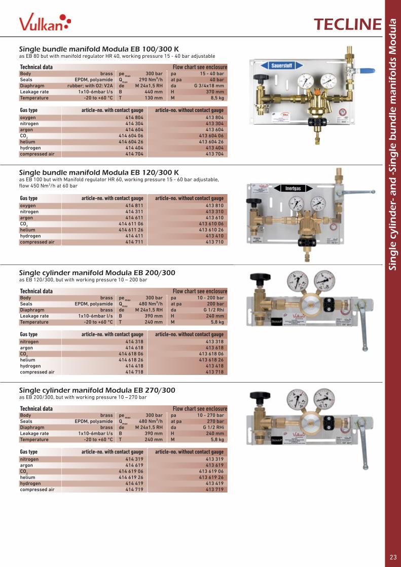
Single bundle manifold Modula EB 120/300 Kas EB 100 but with Manifold regulator HR 60, working pressure 15 - 60 bar adjustable, flow 450 Nm3/h at 60 bar
Gas type article-no. with contact gauge article-no. without contact gauge
Single bundle manifold Modula EB 100/300 Kas EB 80 but with manifold regulator HR 40, working pressure 15 - 40 bar adjustable
Technical data Flow chart see enclosureBody brass pe max 300 bar pa 15 - 40 barSeals EPDM, polyamide Qmax 290 Nm³/h at pa 40 barDiaphragm rubber; with O2: V2A de M 24x1,5 RH da G 3/4x18 mmLeakage rate 1x10⁻⁶mbar l/s B 440 mm H 370 mmTemperature -20 to +60 °C T 130 mm M 8,5 kg
Gas type article-no. with contact gauge article-no. without contact gauge oxygen 414 804 413 804nitrogen 414 304 413 304argon 414 604 413 604CO2 414 604 06 413 604 06helium 414 604 26 413 604 26hydrogen 414 404 413 404compressed air 414 704 413 704
oxygen 414 811 413 810nitrogen 414 311 413 310argon 414 611 413 610CO2 414 611 06 413 610 06helium 414 611 26 413 610 26hydrogen 414 411 413 410compressed air 414 711 413 710
Single cylinder manifold Modula EB 200/300 as EB 120/300, but with working pressure 10 – 200 bar
Single cylinder manifold Modula EB 270/300 as EB 200/300, but with working pressure 10 – 270 bar
Technical data Flow chart see enclosureBody brass pe max 300 bar pa 10 - 200 barSeals EPDM, polyamide Qmax 480 Nm³/h at pa 200 barDiaphragm brass de M 24x1,5 RH da G 1/2 RhiLeakage rate 1x10⁻⁶mbar l/s B 390 mm H 240 mmTemperature -20 to +60 °C T 240 mm M 5,8 kg
Technical data Flow chart see enclosureBody brass pe max 300 bar pa 10 - 270 barSeals EPDM, polyamide Qmax 480 Nm³/h at pa 270 barDiaphragm brass de M 24x1,5 RH da G 1/2 RHiLeakage rate 1x10⁻⁶mbar l/s B 390 mm H 240 mmTemperature -20 to +60 °C T 240 mm M 5,8 kg
Gas type article-no. with contact gauge article-no. without contact gauge
Gas type article-no. with contact gauge article-no. without contact gauge
nitrogen 414 318 413 318argon 414 618 413 618CO2 414 618 06 413 618 06helium 414 618 26 413 618 26hydrogen 414 418 413 418compressed air 414 718 413 718
nitrogen 414 319 413 319argon 414 619 413 619CO2 414 619 06 413 619 06helium 414 619 26 413 619 26hydrogen 414 419 413 419compressed air 414 719 413 719

24
Cyl
ind
er a
nd
bu
nd
le h
ose
s V
areo TECLINE
HP-rubber hose Vareorubber hose to connect cylinders or bundles to rail systems or manifolds, polyamide inside and 1 brass coated steel netting, outside polyuretane, with anti kink spring, complete assembled and tested
HP-Rubber hose Vareo 200 bar connection connection article-no. article-no. article-no. article-no. article-no. article-no. to cylinder an Vareo length 800mm length 1.000mm length 1.500mm length 2.000mm length 2.500mm length 3.000mmacetylene Clamp W21,8x1/14 LH 410 020 0008 410 020 0010 410 020 0015 410 020 0020 410 020 0025 410 020 0030inert gases W21,8x1/14 RH M24x1,5 RH 422 635 0008 422 635 0010 422 635 0015 422 635 0020 422 635 0025 422 635 0030nitrogen W24,32x1/14 RH M24x1,5 RH 422 335 0008 422 335 0010 422 335 0015 422 335 0020 422 335 0025 422 335 0030fuel gases W21,8x1/14 LH M24x1,5 RH 422 435 0008 422 435 0010 422 435 0015 422 435 0020 422 435 0025 422 435 0030compressed air G 5/8 RH M24x1,5 RH 422 735 0008 422 735 0010 422 735 0015 422 735 0020 422 735 0025 422 735 0030
connection connection article-no. article-no. article-no. article-no. article-no. article-no. to cylinder an Vareo length 800mm length 1.000mm length 1.500mm length 2.000mm length 2.500mm length 3.000mmoxygen G 3/4 RH M24x1,5 RH 425 835 0008 425 835 0010 425 835 0015 425 835 0020 425 835 0025 425 835 0030inert gases W21,8x1/14 RH M24x1,5 RH 425 635 0008 425 635 0010 425 635 0015 425 635 0020 425 635 0025 425 635 0030nitrogen W24,32x1/14 RH M24x1,5 RH 425 335 0008 425 335 0010 425 335 0015 425 335 0020 425 335 0025 425 335 0030fuel gases W21,8x1/14 LH M24x1,5 RH 425 435 0008 425 435 0010 425 435 0015 425 435 0020 425 435 0025 425 435 0030compressed air G 5/8 RH M24x1,5 RH 425 735 0008 425 735 0010 425 735 0015 425 735 0020 425 735 0025 425 735 0030
HP-Rubber hose Vareo 300 bar connection connection article-no. article-no. article-no. article-no. article-no. article-no. to cylinder an Vareo length 800mm length 1.000mm length 1.500mm length 2.000mm length 2.500mm length 3.000mminert gases W30x2 RH M24x1,5 RH 423 635 0008 423 635 0010 423 635 0015 423 635 0020 423 635 0025 423 635 0030nitrogen W30x2 RH M24x1,5 RH 423 335 0008 423 335 0010 423 335 0015 423 335 0020 423 335 0025 423 335 0030fuel gases W30x2 LH M24x1,5 RH 423 435 0008 423 435 0010 423 435 0015 423 435 0020 423 435 0025 423 435 0030compressed air W30x2 RH M24x1,5 RH 423 735 0008 423 735 0010 423 735 0015 423 735 0020 423 735 0025 423 735 0030
connection connection article-no. article-no. article-no. article-no. article-no. article-no. to cylinder an Vareo length 800mm length 1.000mm length 1.500mm length 2.000mm length 2.500mm length 3.000mmoxygen W30x2 RH M24x1,5 RH 424 835 0008 424 835 0010 424 835 0015 424 835 0020 424 835 0025 424 835 0030inert gases W30x2 RH M24x1,5 RH 424 635 0008 424 635 0010 424 635 0015 424 635 0020 424 635 0025 424 635 0030nitrogen W30x2 RH M24x1,5 RH 424 335 0008 424 335 0010 424 335 0015 424 335 0020 424 335 0025 424 335 0030fuel gases W30x2 LH M24x1,5 RH 424 435 0008 424 435 0010 424 435 0015 424 435 0020 424 435 0025 424 435 0030compressed air W30x2 RH M24x1,5 RH 424 735 0008 424 735 0010 424 735 0015 424 735 0020 424 735 0025 424 735 0030
HP-Stainless steel hose Vareostainless steel hose to connect cylinders and bundles to rail systems for manifolds, inside stainless steel tube, outside netting from stainless steel wire with anti kink springs, complete welded and tested
HP-Stainless steel hose Vareo 300 bar
HP-Stainless steel hose Vareo 200 bar
Technical data inner tube polyamide cover polyurethanebrading 2x brass-coated steelPS max 300 barDN 6 mm
Technical data inner tube corrugated tube 316Ti braiding 1x stainless steel 304complete welded with anti kink springsPS max 300 barDN 6 mm
25
Cyl
ind
er a
nd
bu
nd
le h
ose
s st
and
ardTECLINE
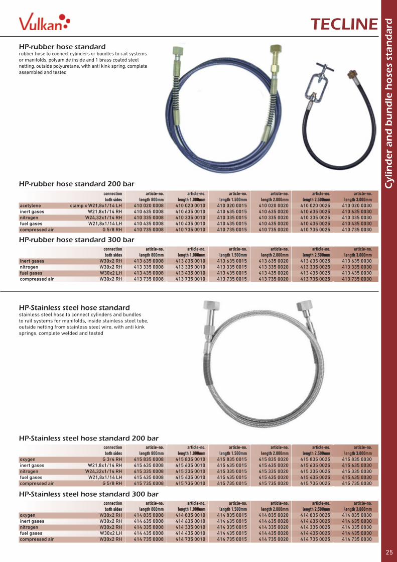
HP-rubber hose standard 200 bar connection article-no. article-no. article-no. article-no. article-no. article-no. both sides length 800mm length 1.000mm length 1.500mm length 2.000mm length 2.500mm length 3.000mmacetylene clamp x W21,8x1/14 LH 410 020 0008 410 020 0010 410 020 0015 410 020 0020 410 020 0025 410 020 0030inert gases W21,8x1/14 RH 410 635 0008 410 635 0010 410 635 0015 410 635 0020 410 635 0025 410 635 0030nitrogen W24,32x1/14 RH 410 335 0008 410 335 0010 410 335 0015 410 335 0020 410 335 0025 410 335 0030fuel gases W21,8x1/14 LH 410 435 0008 410 435 0010 410 435 0015 410 435 0020 410 435 0025 410 435 0030compressed air G 5/8 RH 410 735 0008 410 735 0010 410 735 0015 410 735 0020 410 735 0025 410 735 0030
connection article-no. article-no. article-no. article-no. article-no. article-no. both sides length 800mm length 1.000mm length 1.500mm length 2.000mm length 2.500mm length 3.000mmoxygen G 3/4 RH 415 835 0008 415 835 0010 415 835 0015 415 835 0020 415 835 0025 415 835 0030inert gases W21,8x1/14 RH 415 635 0008 415 635 0010 415 635 0015 415 635 0020 415 635 0025 415 635 0030nitrogen W24,32x1/14 RH 415 335 0008 415 335 0010 415 335 0015 415 335 0020 415 335 0025 415 335 0030fuel gases W21,8x1/14 LH 415 435 0008 415 435 0010 415 435 0015 415 435 0020 415 435 0025 415 435 0030compressed air G 5/8 RH 415 735 0008 415 735 0010 415 735 0015 415 735 0020 415 735 0025 415 735 0030
HP-rubber hose standard 300 bar connection article-no. article-no. article-no. article-no. article-no. article-no. both sides length 800mm length 1.000mm length 1.500mm length 2.000mm length 2.500mm length 3.000mminert gases W30x2 RH 413 635 0008 413 635 0010 413 635 0015 413 635 0020 413 635 0025 413 635 0030nitrogen W30x2 RH 413 335 0008 413 335 0010 413 335 0015 413 335 0020 413 335 0025 413 335 0030fuel gases W30x2 LH 413 435 0008 413 435 0010 413 435 0015 413 435 0020 413 435 0025 413 435 0030compressed air W30x2 RH 413 735 0008 413 735 0010 413 735 0015 413 735 0020 413 735 0025 413 735 0030
connection article-no. article-no. article-no. article-no. article-no. article-no. both sides length 800mm length 1.000mm length 1.500mm length 2.000mm length 2.500mm length 3.000mmoxygen W30x2 RH 414 835 0008 414 835 0010 414 835 0015 414 835 0020 414 835 0025 414 835 0030inert gases W30x2 RH 414 635 0008 414 635 0010 414 635 0015 414 635 0020 414 635 0025 414 635 0030nitrogen W30x2 RH 414 335 0008 414 335 0010 414 335 0015 414 335 0020 414 335 0025 414 335 0030fuel gases W30x2 LH 414 435 0008 414 435 0010 414 435 0015 414 435 0020 414 435 0025 414 435 0030compressed air W30x2 RH 414 735 0008 414 735 0010 414 735 0015 414 735 0020 414 735 0025 414 735 0030
HP-Stainless steel hose standard 300 bar
HP-Stainless steel hose standard 200 bar
HP-rubber hose standardrubber hose to connect cylinders or bundles to rail systems or manifolds, polyamide inside and 1 brass coated steel netting, outside polyuretane, with anti kink spring, complete assembled and tested
HP-Stainless steel hose standardstainless steel hose to connect cylinders and bundles to rail systems for manifolds, inside stainless steel tube, outside netting from stainless steel wire, with anti kink springs, complete welded and tested
26
Cyl
ind
er a
nd
bu
nd
le h
ose
s st
and
ard
an
d V
areo TECLINE
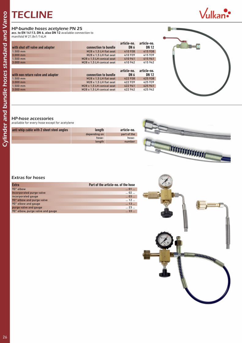
HP-bundle hoses acetylene PN 25acc. to EN 14113, DN 6, also DN 12 available connection to manifold W 21,8x1/14LH
article-no. article-no.with shut off valve and adapter connection to bundle DN 6 DN 121.500 mm M28 x 1,5 LH flat seat 410 938 415 9383.000 mm M28 x 1,5 LH flat seat 410 939 415 9391.500 mm M28 x 1,5 LH conical seat 410 941 415 9413.000 mm M28 x 1,5 LH conical seat 410 942 415 942
article-no. article-no.with non return valve and adapter connection to bundle DN 6 DN 121.500 mm M28 x 1,5 LH flat seat 422 938 425 9383.000 mm M28 x 1,5 LH flat seat 422 939 425 9391.500 mm M28 x 1,5 LH conical seat 422 941 425 9413.000 mm M28 x 1,5 LH conical seat 422 942 425 942
HP-hose accessoriesavailable for every hose except for acetylene
anti whip cable with 2 sheet steel angles length article-no. depending on part of the hose- hose- length number
Extra Part of the article-no. of the hose90° elbow ... 01 ...Incorporated purge valve ... 02 ...incorporated gauge ... 03 ...90° elbow and purge valve ... 12 ...90° elbow and gauge ... 13 ...purge valve and gauge ... 23 ...90° elbow, purge valve and gauge ... 33 ...
Extras for hoses

27
Tap
pin
g p
oin
t V
ulk
anTECLINE Tapping point regulator Vulkan E 10single stage, with working gauge to adjust the working pressure at point of use and connection to tapping point
Tapping point regulator Vulkan E 10 Fsingle stage with flowmeter and regulating valve for precise adjustment of aconstant working flow
Tapping point regulator Vulkan E 20single stage, with working gauge, adjustable 0 - 20 bar
Technical data Flow chart see enclosureBody brass pe max 20 bar pa 0 - 10 barSeals EPDM Qmax see below at pa 10 barDiaphragm Perbunan de G 3/8 RH/LH da see belowLeakage rate 1x10⁻⁶mbar l/s B 120 mm H 160 mmTemperature -20 to +60 °C T 65 mm M 1,0 kg
Technical data Body brass pe max 20 bar pa 1,5 barSeals EPDM Qmax see below at pa 1,5 barDiaphragm Perbunan de G 3/8 RH/LH da see belowLeakage rate 1x10⁻⁶mbar l/s B 120 mm H 210 mmTemperature -20 to +60 °C T 65 mm M 1,0 kg
Technical data Flow chart see enclosureBody brass pe max 40 bar pa see belowSeals EPDM, polyamide, PTFE Qmax see below at pa see belowDiaphragm EPDM/PTFE de G 1/2 RH/LH da see belowLeakage rate 1x10⁻⁶mbar l/s B 180 mm H 225 mmTemperature -20 to +60 °C T 75 mm M 1,7 kg
Gas type inlet pressure pressure flow inlet outlet article-no.oxygen 20 bar 0 - 10 bar 46 Nm³/h G 3/8 RH nut G 1/4 RH x 6 mm 108 700acetylene 1,5 bar 0 - 1,5 bar 3,5 Nm³/h G 3/8 LH nut G 3/8 LH x 9 mm 109 700CO2 /argon 20 bar 0 - 10 bar 46 Nm³/h G 3/8 RH nut G 1/4 RH x 6 mm 126 700 ” ” 0 - 20 Nl/min. ” ” 126 720 „ „ 0 - 30 Nl/min. „ „ 126 725 ” 0 - 4 bar 0 - 30 Nl/min. ” ” 126 728helium ” 0 - 10 bar 46 Nm³/h ” ” 126 706nitrogen ” ” ” ” ” 103 700hydrogen ” ” ” G 3/8 LH nut G 3/8 LH x 9 mm 104 700forming gas ” ” ” ” ” 104 845 ” ” 0 - 20 Nl/min. ” ” 104 843 ” ” 0 - 30 Nl/min. ” ” 104 841 ” ” 0 - 50 Nl/min. ” ” 104 842compressed air ” ” 46 Nm³/h G 3/8 RH nut G 1/4 RH x 6 mm 107 700testing gas ” ” 46 Nm³/h G 3/8 LH nut G 3/8 LH x 9 mm 103 800nitrous oxide ” ” 46 Nm³/h G 3/8 RH nut G 1/4 RH x 6 mm 102 070propane 8 bar 0 - 4 bar 5 kg/h G 3/8 LH nut G 3/8 LH x 9 mm 105 700 8 bar 0 - 2,5 bar 2,5 kg/h ” ” 105 750ethene ” 0 - 1,5 bar 3,5 Nm³/h ” ” 105 760methane ” 0 - 1,5 bar 3,5 Nm³/h ” ” 105 770
Gas type inlet pressure pressure flow inlet outlet article-no.oxygen 40 bar 0 - 20 bar 75 Nm³/h G 1/2 RH nut G 1/2 RH x 9 mm 108 720acetylene 1,5 bar 0 - 1,5 bar 5 Nm³/h G 1/2 LH nut G 1/2 LH x 9 mm 109 720CO2 /argon 40 bar 0 - 20 bar 75 Nm³/h G 1/2 RH nut G 1/2 RH x 9 mm 106 720helium ” ” ” ” ” 106 726nitrogen ” ” ” ” ” 103 720hydrogen ” ” ” G 1/2 LH nut G 1/2 LH x 9 mm 104 720forming gas ” ” ” ” ” 104 820compressed air ” ” ” G 1/2 RH nut G 1/2 RH x 9 mm 107 720propane 8 bar 0 - 4,0 bar 10 kg/h G 1/2 LH nut G 1/2 LH x 9 mm 105 720
Gas type flow range pressure inlet outlet article-no.oxygen 1,4 - 14,5 Nl/min. 1,5 bar G 3/8 RH nut G 1/4 RH x 6 mm 108 715CO2 /argon 1,0 – 6,5 Nl/min. 4,0 bar „ „ 102 725 1,4 - 14,0 Nl/min. 1,5 bar „ „ 102 700 3,0 - 22,0 Nl/min. „ „ „ 102 720 3,6 - 36,0 Nl/min. „ „ „ 102 750 10,0 - 95,0 Nl/min. 9,0 bar „ „ 102 710helium 3,6 – 34,0 Nl/min. 1,5 bar „ „ 104 724 5, 0 - 65,0 Nl/min. „ „ „ 104 725nitrogen 0,3 - 2,0 Nl/min. „ „ „ 103 745 4,0 - 42 Nl/min. „ „ „ 103 750 8,5 - 85,0 Nl/min. 4,0 bar „ „ 103 775hydrogen 1,8 -18,0 Nl/min. 1,5 bar G 3/8 LH nut G 3/8 LH x 9 mm 104 750 2,6 - 26 Nl/min. „ „ „ 104 755forming gas 2,0 - 23,0 Nl/min. „ „ „ 104 723

28
Tap
pin
g p
oin
t V
ulk
an TECLINETapping point regulator Vulkan E 40single stage, with working gauge, adjustable 0 - 40 bar
Tapping point fin regulator Vulkan ER 20single stage, with working gauge, adjustable 0 - 20 bar
Tapping point fin regulator Vulkan ER 40single stage, with working gauge, adjustable 15 - 40 bar
Tapping point Vulkan Alu-Line 3/8complete on aluminium profile, horizontally adjustable, with shut off valveand brazing connecting pieces for connection to piping system Ø 12 mm,connection for tapping point regulator G3/8RH or LH, PN 40, for acetylene PN 1,5
Technical data Flow chart see enclosureBody brass pe max 60 bar pa 0 - 40 barSeals EPDM, polyamide, PTFE Qmax see below at pa 40 barDiaphragm PTFE, oxygen: V2A de G 1/2 RH/LH da see belowLeakage rate 1x10⁻⁶mbar l/s B 180 mm H 225 mmTemperature -20 to +60 °C T 75 mm M 1,7 kg
Technical data Flow chart see enclosureBody brass pe max 100 bar pa 0 - 20 barSeals polyamide, NBR Qmax see below at pa 20 barDiaphragm rubber de G 1/2 RH/LH da see belowLeakage rate 1x10⁻⁶mbar l/s B 240 mm H 240 mmTemperature -20 to +60 °C T 100 mm M 3 kg
Technical data Flow chart see enclosureBody brass pe max 100 bar pa 15 - 40 barSeals polyamide, NBR Qmax see below at pa 40 barDiaphragm rubber, with O2:VA de G 1/2 RH/LH da see belowLeakage rate 1x10⁻⁶mbar l/s B 240 mm H 330 mmTemperature -20 to +60 °C T 100 mm M 3,8 kg
for 1 tapping point regulator oxygen acetylene fuel gases inert gas propane compressed air 400 21 001 400 21 002 400 21 003 400 21 004 400 21 005 400 21 007
For 2 tapping point regulators oxygen acetylene fuel gases inert gas propane compressed air oxygen 400 22 011 400 22 012 400 22 013 400 22 014 400 22 015 400 22 017acetylene 400 22 022 400 22 023 400 22 024 400 220 25 400 22 027fuel gases 400 22 033 400 22 034 400 22 035 400 22 037inert gas 400 22 044 400 22 045 400 22 047propane 400 22 055 400 22 057compressed air 400 22 077
Gas type inlet pressure pressure flow inlet outlet article-no.oxygen 60 bar 40 bar 120 Nm³/h G 1/2 RH nut G 1/2 RH x 9 mm 118 730CO2 /argon ” ” ” ” ” 106 730helium ” ” ” ” ” 106 736nitrogen ” ” ” ” ” 103 730hydrogen ” ” ” G 1/2 LH nut G 1/2 LH x 9 mm 104 730forming gas ” ” ” ” ” 104 830compressed air ” ” ” G 1/2 RH nut G 1/2 RH x 9 mm 107 730
Gas type inlet pressure pressure flow inlet outlet article-no.oxygen 100 bar 0 - 20 bar 160 Nm³/h G 1/2 RH nut G 1/2 RH 108 735CO2 /argon ” ” ” ” ” 106 735helium ” ” ” ” ” 106 735 26nitrogen ” ” ” ” ” 103 735hydrogen ” ” ” G 1/2 LH nut G 1/2 LH 104 735forming gas ” ” ” ” G 1/2 LH 104 835compressed air ” ” ” G 1/2 RH nut G 1/2 RH 107 735
Gas type inlet pressure pressure flow inlet outlet article-no.oxygen 100 bar 15 -40 bar 280 Nm³/h G 1/2 RH nut G 1/2 RH 118 740CO2 /argon ” ” ” ” ” 106 740helium ” ” ” ” ” 106 746nitrogen ” ” ” ” ” 103 740hydrogen ” ” ” G 1/2 LH nut G 1/2 LH 104 740forming gas ” ” ” ” ” 104 840compressed air ” ” ” G 1/2 RH nut G 1/2 RH 107 740

29
Tap
pin
g p
oin
t V
ulk
anTECLINE
Shipyard tapping point Vulkan Alu-Line ST 3/8complete on aluminium bar, distance between each outlet 85 mm, with distributing pipe and block ball valve, one inlet with shut off valves for each outlet, for fuel gases, inert gases, and oxygen for up to 10 tapping point regulators, inlet with 2 connections G 1/2RH, with more than 2 connections G3/4RH, outlets G 3/8RH or LH, PN 40, for acetylene PN 1,5
Shipyard tapping point Vulkan Alu-Line ST 1/2as shipyard tapping point Alu-Line St 3/8 but outlets G 1/2RH/LHak and inlets G 3/4RHi, interval 120 mm
quantity connections oxygen acetylene fuel gases inert gas propane compressed air 2 415 041 01 415 041 02 415 041 03 415 041 04 415 041 05 415 041 07 3 415 043 01 415 043 02 415 043 03 415 043 04 415 043 05 415 043 07 4 415 045 01 415 045 02 415 045 03 415 045 04 415 045 05 415 045 07 5 415 047 01 415 047 02 415 047 03 415 047 04 415 047 05 415 047 07 6 415 049 01 415 049 02 415 049 03 415 049 04 415 049 05 415 049 07 7 415 051 01 415 051 02 415 051 03 415 051 04 415 051 05 415 051 07 8 415 053 01 415 053 02 415 053 03 415 053 04 415 053 05 415 053 07 9 415 055 01 415 055 02 415 055 03 415 055 04 415 055 05 415 055 07 10 415 057 01 415 057 02 415 057 03 415 057 04 415 057 05 415 057 07
quantity connections oxygen acetylene fuel gases inert gas propane compressed air 2 415 241 01 415 241 02 415 241 03 415 241 04 415 241 05 415 241 07 3 415 243 01 415 243 02 415 243 03 415 243 04 415 243 05 415 243 07 4 415 245 01 415 245 02 415 245 03 415 245 04 415 245 05 415 245 07 5 415 247 01 415 247 02 415 247 03 415 247 04 415 247 05 415 247 07 6 415 249 01 415 249 02 415 249 03 415 249 04 415 249 05 415 249 07 7 415 251 01 415 251 02 415 251 03 415 251 04 415 251 05 415 251 07 8 415 253 01 415 253 02 415 253 03 415 253 04 415 253 05 415 253 07 9 415 255 01 415 255 02 415 255 03 415 255 04 415 255 05 415 255 07 10 415 257 01 415 257 02 415 257 03 415 257 04 415 257 05 415 257 07
For 1 tapping point regulator oxygen acetylene fuel gases inert gas propane compressed air 415 21 001 415 21 0002 415 21 003 415 21 004 415 21 005 415 21 007
For 2 tapping point regulators oxygen acetylene fuel gases inert gas propane compressed airoxygen 415 22 011 415 22 012 415 22 013 415 22 014 415 22 015 415 22 017acetylene 415 22 022 415 22 023 415 22 024 415 22 025 415 22 027fuel gases 415 22 033 415 22 034 415 22 035 415 22 037inert gas 415 22 044 415 22 045 415 22 047propane 415 22 055 415 22 057compressed air 415 22 077
Tapping point Vulkan Alu-Line 1/2 NDas tapping point 3/8 with connection G 1/2 for higher flow, PN 40, for acetylene PN 1,5
For 1 tapping point regulator oxygen acetylene fuel gases inert gas propane compressed air 418 21 001 418 21 0002 418 21 003 418 21 004 418 21 005 418 21 007
For 2 tapping point regulators oxygen acetylene fuel gases inert gas propane compressed airoxygen 418 22 011 418 22 012 418 22 013 418 22 014 418 22 015 418 22 017fuel gases 418 22 033 418 22 034 418 22 035 418 22 037inert gas 418 22 044 418 22 045 418 22 047compressed air 418 22 077
Tapping point Vulkan Alu Line 1/2 MDas tapping point 1/2 ND with connection G 1/2 for higher pressure, PN 100, for acetylene PN 1,5
For 1 tapping point regulator oxygen acetylene fuel gases inert gas propane compressed air 415 31 001 415 31 0002 415 31 003 415 31 004 415 31 005 415 31 007
For 2 tapping point regulators oxygen acetylene fuel gases inert gas propane compressed airoxygen 415 32 011 415 32 012 415 32 013 415 32 014 415 32 015 415 32 017acetylene 415 32 022 415 32 023 415 32 024 415 32 025 415 32 027fuel gases 415 32 033 415 32 034 415 32 035 415 32 037inert gas 415 32 044 415 32 045 415 32 047propane 415 32 055 415 32 057compressed air 415 32 077
Tapping point Vulkan Alu Line 1/2 GUas tapping point 1/2 ND with connection G 1/2 for higher pressure, PN 40, but with outlet downwards for e.g. LH40 or LH25

30
Man
ifo
ld r
egu
lato
r V
ulk
an a
cc. t
o IS
O 7
29
1 TECLINEManifold regulator Vulkan HA 5 acetyleneacc. to ISO 7291
Hauptdruckminderer Vulkan HA 10 acetylenenach ISO 7291
Manifold regulator Vulkan HA 40 acetyleneacc. to ISO 7291
Manifold regulator Vulkan H 20 acetylene Effectwith high pressure compensation for a constant working pressure, acc. to ISO 7291, for high flow and high pressure especially suitable for flame cutting machines
Manifold regulator Vulkan H 20/300 Effectfor manifolds or direct connection to a bundle, acc. to ISO 7291, adiabatic compression tested
Technical data Flow chart see enclosureBody brass pe max 26 bar pa 0 - 1,5 barSeals EPDM Qmax 5 Nm³/h at pa 1,5 barDiaphragm EPDM de G 3/4 LH nut da G 1/2 RHakLeakage rate 1x10⁻⁶mbar l/s B 200 mm H 190 mmTemperature -20 to +60 °C T 75 mm M 1,5 kg
Technical data Flow chart see enclosureBody brass pe max 26 bar pa 0 - 1,5 barSeals EPDM Qmax 10 Nm³/h at pa 1,5 barDiaphragm EPDM de G 3/4 LH nut da G 1/2 RHakLeakage rate 1x10⁻⁶mbar l/s B 200 mm H 190 mmTemperature -20 to +60 °C T 75 mm M 1,5 kg
Technical data Flow chart see enclosureBody brass pe max 26 bar pa 0 - 1,5 barSeals EPDM Qmax 18 Nm³/h at pa 1,5 barDiaphragm EPDM de G 3/4 LH nut da G 1/2 RHakLeakage rate 1x10⁻⁶mbar l/s B 250 mm H 190 mmTemperature -20 to +60 °C T 75 mm M 1,7 kg
Technical data Flow chart see enclosureBody brass pe max 26 bar pa 0 - 1,5 barSeals EPDM Qmax 40 Nm³/h at pa 1,5 barDiaphragm EPDM de 16 mm da 22 mmLeakage rate 1x10⁻⁶mbar l/s B 195 mm H 275 mmTemperature -20 to +60 °C T 135 mm M 5,5 kg
Technical data Flow chart see enclosureBody brass pe max 200/300 bar pa 0 - 20 barSeals EPDM, polyamide, PTFE Qmax 75 Nm³/h at pa 20 barDiaphragm PTFE de see below da see belowLeakage rate 1x10⁻⁶mbar l/s B 200 mm H 190 mmTemperature -20 to +60 °C T 75 mm M 1,7 kg
gas type inlet pressure inlet outlet article-no.acetylene 26 bar G 3/4 LH G 1/2 RH 209 520
gas type inlet pressure inlet outlet article-no.acetylene 26 bar G 3/4 LH G 1/2 RH 209 510
gas type inlet pressure inlet outlet article-no.acetylene 26 bar G 3/4 LH G 1/2 RH 209 511
gas type inlet pressure inlet outlet article-no.acetylene 26 bar 16 mm 22 mm 209 530
gas type inlet pressure inlet outlet article-no.oxygen 200 bar G 3/4 RH nut G1/2RH 208 520CO2 /argon ” W21,8x1/14RH nut ” 206 520helium ” ” ” 206 520 26nitrogen ” W24,32x1/14RH nut ” 203 520hydrogen ” W21,8x1/14LH nut ” 204 520compressed air ” G 5/8 RH ÜS ” 207 520oxygen 300 bar W30x2 RH nut G1/2RH 308 520CO2 /argon ” ” ” 306 520helium ” ” ” 306 520 26nitrogen ” ” ” 303 520hydrogen ” W30x2 LH nut ” 304 520compressed air ” W30x2 RH nut ” 307 520
31
Man
ifo
ld r
egu
lato
r V
ulk
an a
cc. t
o IS
O 7
29
1TECLINE
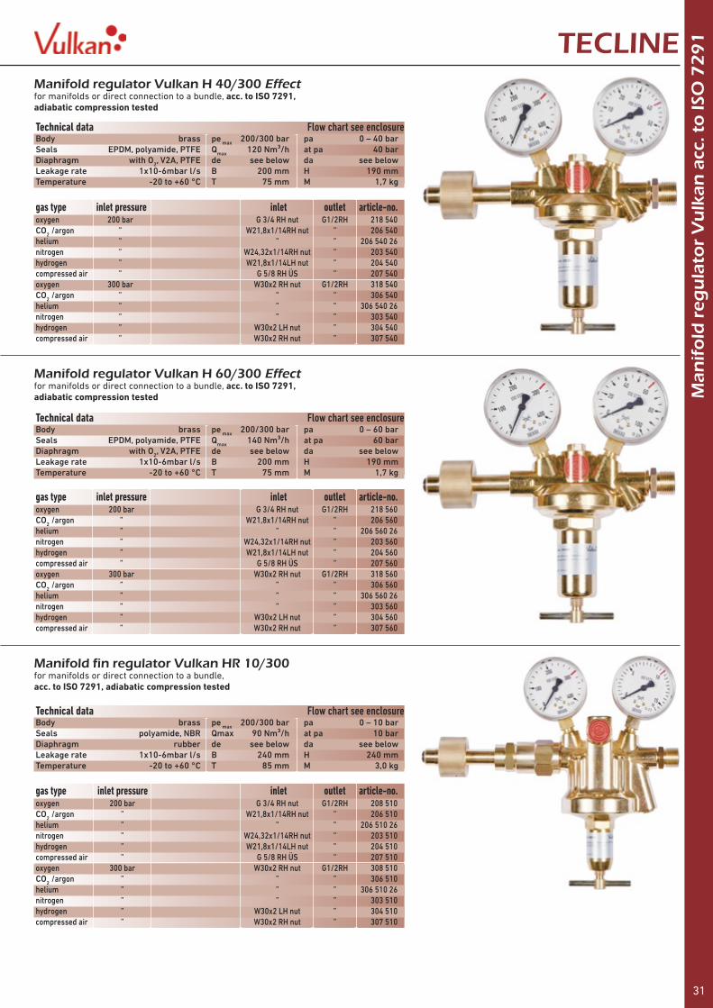
Manifold fin regulator Vulkan HR 10/300for manifolds or direct connection to a bundle,acc. to ISO 7291, adiabatic compression tested
Technical data Flow chart see enclosureBody brass pe max 200/300 bar pa 0 – 10 barSeals polyamide, NBR Qmax 90 Nm³/h at pa 10 barDiaphragm rubber de see below da see belowLeakage rate 1x10⁻⁶mbar l/s B 240 mm H 240 mmTemperature -20 to +60 °C T 85 mm M 3,0 kg
gas type inlet pressure inlet outlet article-no.oxygen 200 bar G 3/4 RH nut G1/2RH 208 510CO2 /argon ” W21,8x1/14RH nut ” 206 510helium ” ” ” 206 510 26nitrogen ” W24,32x1/14RH nut ” 203 510hydrogen ” W21,8x1/14LH nut ” 204 510compressed air ” G 5/8 RH ÜS ” 207 510oxygen 300 bar W30x2 RH nut G1/2RH 308 510CO2 /argon ” ” ” 306 510helium ” ” ” 306 510 26nitrogen ” ” ” 303 510hydrogen ” W30x2 LH nut ” 304 510compressed air ” W30x2 RH nut ” 307 510
Manifold regulator Vulkan H 40/300 Effectfor manifolds or direct connection to a bundle, acc. to ISO 7291, adiabatic compression tested
Technical data Flow chart see enclosureBody brass pe max 200/300 bar pa 0 – 40 barSeals EPDM, polyamide, PTFE Qmax 120 Nm³/h at pa 40 barDiaphragm with O2, V2A, PTFE de see below da see belowLeakage rate 1x10⁻⁶mbar l/s B 200 mm H 190 mmTemperature -20 to +60 °C T 75 mm M 1,7 kg
gas type inlet pressure inlet outlet article-no.oxygen 200 bar G 3/4 RH nut G1/2RH 218 540CO2 /argon ” W21,8x1/14RH nut ” 206 540helium ” ” ” 206 540 26nitrogen ” W24,32x1/14RH nut ” 203 540hydrogen ” W21,8x1/14LH nut ” 204 540compressed air ” G 5/8 RH ÜS ” 207 540oxygen 300 bar W30x2 RH nut G1/2RH 318 540CO2 /argon ” ” ” 306 540helium ” ” ” 306 540 26nitrogen ” ” ” 303 540hydrogen ” W30x2 LH nut ” 304 540compressed air ” W30x2 RH nut ” 307 540
Manifold regulator Vulkan H 60/300 Effectfor manifolds or direct connection to a bundle, acc. to ISO 7291, adiabatic compression tested
Technical data Flow chart see enclosureBody brass pe max 200/300 bar pa 0 – 60 barSeals EPDM, polyamide, PTFE Qmax 140 Nm³/h at pa 60 barDiaphragm with O2, V2A, PTFE de see below da see belowLeakage rate 1x10⁻⁶mbar l/s B 200 mm H 190 mmTemperature -20 to +60 °C T 75 mm M 1,7 kg
gas type inlet pressure inlet outlet article-no.oxygen 200 bar G 3/4 RH nut G1/2RH 218 560CO2 /argon ” W21,8x1/14RH nut ” 206 560helium ” ” ” 206 560 26nitrogen ” W24,32x1/14RH nut ” 203 560hydrogen ” W21,8x1/14LH nut ” 204 560compressed air ” G 5/8 RH ÜS ” 207 560oxygen 300 bar W30x2 RH nut G1/2RH 318 560CO2 /argon ” ” ” 306 560helium ” ” ” 306 560 26nitrogen ” ” ” 303 560hydrogen ” W30x2 LH nut ” 304 560compressed air ” W30x2 RH nut ” 307 560
32
Man
ifo
ld r
egu
lato
r V
ulk
an a
cc. t
o IS
O 7
29
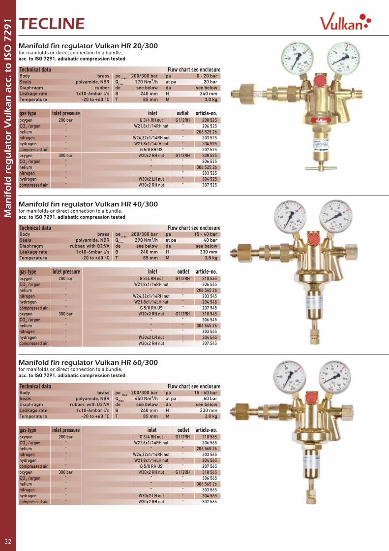
1 TECLINEManifold fin regulator Vulkan HR 20/300for manifolds or direct connection to a bundle,acc. to ISO 7291, adiabatic compression tested
Manifold fin regulator Vulkan HR 40/300for manifolds or direct connection to a bundle,acc. to ISO 7291, adiabatic compression tested
Manifold fin regulator Vulkan HR 60/300for manifolds or direct connection to a bundle,acc. to ISO 7291, adiabatic compression tested
Technical data Flow chart see enclosureBody brass pe max 200/300 bar pa 0 - 20 barSeals polyamide, NBR Qmax 170 Nm³/h at pa 20 barDiaphragm rubber de see below da see belowLeakage rate 1x10⁻⁶mbar l/s B 240 mm H 240 mmTemperature -20 to +60 °C T 85 mm M 3,0 kg
Technical data Flow chart see enclosureBody brass pe max 200/300 bar pa 15 - 40 barSeals polyamide, NBR Qmax 290 Nm³/h at pa 40 barDiaphragm rubber, with O2:VA de see below da see belowLeakage rate 1x10⁻⁶mbar l/s B 240 mm H 330 mmTemperature -20 to +60 °C T 85 mm M 3,8 kg
Technical data Flow chart see enclosureBody brass pe max 200/300 bar pa 15 - 60 barSeals polyamide, NBR Qmax 450 Nm³/h at pa 60 barDiaphragm rubber, with O2:VA de see below da see belowLeakage rate 1x10⁻⁶mbar l/s B 240 mm H 330 mmTemperature -20 to +60 °C T 85 mm M 3,8 kg
gas type inlet pressure inlet outlet article-no.oxygen 200 bar G 3/4 RH nut G1/2RH 208 525CO2 /argon ” W21,8x1/14RH nut ” 206 525helium ” ” ” 206 525 26nitrogen ” W24,32x1/14RH nut ” 203 525hydrogen ” W21,8x1/14LH nut ” 204 525compressed air ” G 5/8 RH ÜS ” 207 525oxygen 300 bar W30x2 RH nut G1/2RH 308 525CO2 /argon ” ” ” 306 525helium ” ” ” 306 525 26nitrogen ” ” ” 303 525hydrogen ” W30x2 LH nut ” 304 525compressed air ” W30x2 RH nut ” 307 525
gas type inlet pressure inlet outlet article-no.oxygen 200 bar G 3/4 RH nut G1/2RH 218 545CO2 /argon ” W21,8x1/14RH nut ” 206 545helium ” ” ” 206 545 26nitrogen ” W24,32x1/14RH nut ” 203 545hydrogen ” W21,8x1/14LH nut ” 204 545compressed air ” G 5/8 RH ÜS ” 207 545oxygen 300 bar W30x2 RH nut G1/2RH 318 545CO2 /argon ” ” ” 306 545helium ” ” ” 306 545 26nitrogen ” ” ” 303 545hydrogen ” W30x2 LH nut ” 304 545compressed air ” W30x2 RH nut ” 307 545
gas type inlet pressure inlet outlet article-no.oxygen 200 bar G 3/4 RH nut G1/2RH 218 565CO2 /argon ” W21,8x1/14RH nut ” 206 565helium ” ” ” 206 565 26nitrogen ” W24,32x1/14RH nut ” 203 565hydrogen ” W21,8x1/14LH nut ” 204 565compressed air ” G 5/8 RH ÜS ” 207 565oxygen 300 bar W30x2 RH nut G1/2RH 318 565CO2 /argon ” ” ” 306 565helium ” ” ” 306 565 26nitrogen ” ” ” 303 565hydrogen ” W30x2 LH nut ” 304 565compressed air ” W30x2 RH nut ” 307 565

33
Man
ifo
ld r
egu
lato
r V
ulk
an a
cc. t
o IS
O 7
29
1TECLINEManifold and in-line regulator Vulkan LHR 300/200 BSPsingle stage, with safety gauges acc. to ISO 5171, in 3 working pressure steps, 270 bar, 200 bar und 100 bar, outlet G 1/2RHak
Manifold and in-line regulator Vulkan LHR 300/200 DINsingle stage, with safety gauges acc. to ISO 5171, in 3 working pressure steps, 270 bar, 200 bar und 100 bar, outlet acc. to DIN 477-1
Technical data Flow chart see enclosureBody brass pe max see below pa see belowSeals EPDM Qmax 480 Nm³/h at pa see belowDiaphragm EPDM de DIN 477 RH/LH da DIN 477 RH/LHLeakage rate 1x10⁻⁶mbar l/s B 150 mm H 210 mmTemperature -20 to +60 °C T 120 mm M 1,2 kg
gas type outlet pressure inlet pressure 200 bar inlet pressure 300 bar article-no. article-no.CO2 /argon 270 bar 306 771helium 270 bar 306 771 26nitrogen 270 bar 303 771hydrogen 270 bar 304 771compressed air 270 bar 307 771oxygen 200 bar 208 770 308 770CO2 /argon 200 bar 206 770 306 770helium 200 bar 206 770 26 306 770 26nitrogen 200 bar 203 770 303 770hydrogen 200 bar 204 770 304 770compressed air 200 bar 207 770 307 770oxygen 100 bar 208 760 308 760CO2 /argon 100 bar 206 760 306 760helium 100 bar 206 760 26 306 760 26nitrogen 100 bar 203 760 303 760hydrogen 100 bar 204 760 304 760compressed air 100 bar 207 760 307 760
gas type outlet outlet pressure inlet pressure 200 bar inlet pressure 300 bar article-no. article-no.oxygen G 3/4RHaf 200 bar 208 775 308 775CO2 /argon W21,8x1/14RHaf 200 bar 206 775 306 775helium W21,8x1/14RHaf 200 bar 206 775 26 306 775 26nitrogen W24,32x1/14RHaf 200 bar 203 775 303 775hydrogen W21,8x1/14LHaf 200 bar 204 775 304 775compress. air G 5/8RHif 200 bar 207 775 307 775oxygen G 3/4RHaf 100 bar 208 765 308 765CO2 /argon W21,8x1/14RHaf 100 bar 206 765 306 765helium W21,8x1/14RHaf 100 bar 206 765 26 306 765 26nitrogen W24,32x1/14RHaf 100 bar 203 765 303 765hydrogen W21,8x1/14LHaf 100 bar 204 765 304 765compress. air G 5/8RHif 100 bar 207 766 307 765
Technical data Flow chart see enclosureBody brass pe max see below pa see belowSeals EPDM Qmax 480 Nm³/h at pa see belowDiaphragm EPDM de DIN 477 RH/LH da G 1/2 RhakLeakage rate 1x10⁻⁶mbar l/s B 150 mm H 210 mmTemperature -20 to +60 °C T 120 mm M 1,2 kg

34
TECLINEM
anif
old
reg
ula
tor
Vu
lkan
acc
. to
ISO
72
91
Manifold regulator Vulkan H 20 for AM 35 / AM 35Hexchange regulator for Automatic manifolds AM 35, 35 K, 35 KM, 35 H, 35 KH and 35 KHM, without contact gauge, in case of order please indicate serial no. of manifold
Manifold regulator Vulkan H40 for AM 40exchange regulator for Automatic manifolds AM 35, 35 K, 35 KM, 35 H, 35 KH and 35 KHM, without contact gauge, in case of order please indicate serial no. of manifold
In-line regulator Vulkan AD 35 (2.stage)exchange regulator for Automatic manifold AM 35, AM 35 K and AM 35 KM
inlet pressure outlet pressure outlet pressure outlet pressure outlet pressuregas type 14 bar left side 14 bar right side 20 bar left side 20 bar right side
inlet pressure left side right sidegas type article-no. article-no.
oxygen 200 bar 208 521 41 208 522 41 208 521 20 208 522 20CO2 /argon ” 206 521 41 206 522 41 206 521 20 206 522 20helium ” 206 521 41 26 206 522 41 26 206 521 20 26 206 522 20 26nitrogen ” 203 521 41 203 522 41 203 521 20 203 522 20hydrogen ” 204 521 41 204 522 41 204 521 20 204 522 20compressed air ” 207 521 41 207 522 41 207 521 20 207 522 20oxygen 300 bar 308 521 41 308 522 41 308 521 20 308 522 20CO2 /argon ” 306 521 41 306 522 41 306 521 20 306 522 20helium ” 306 521 41 26 306 522 41 26 306 521 20 26 306 522 20 26nitrogen ” 303 521 41 303 522 41 303 521 20 303 522 20hydrogen ” 304 521 41 304 522 41 304 521 20 304 522 20compressed air ” 307 521 41 307 522 41 307 521 20 307 522 20
oxygen 200 bar 208 521 40 208 522 40CO2 /argon ” 206 521 40 206 522 40helium ” 206 521 40 26 206 522 40 26nitrogen ” 203 521 40 203 522 40hydrogen ” 204 521 40 204 522 40compressed air ” 207 521 40 207 522 40oxygen 300 bar 308 521 40 308 522 40CO2 /argon ” 306 521 40 306 522 40helium ” 306 521 40 26 306 522 40 26nitrogen ” 303 521 40 303 522 40hydrogen ” 304 521 40 304 522 40compressed air ” 307 521 40 307 522 40
gas type inlet pressure outlet pressure article-no.oxygen 20 bar 0 - 10 bar 108 022CO2 /argon ” ” 106 022helium ” ” 106 022 26nitrogen ” ” 103 022hydrogen ” ” 104 022compressed air ” ” 107 022
Technical data Flow chart see enclosureBody brass pe max 200/300 bar pa see belowSeals EPDM, polyamide, PTFE Qmax 75 Nm³/h at pa 20 barDiaphragm PTFE de M 24x1,5 RHak da G 1/2RHk nutLeakage rate 1x10⁻⁶mbar l/s B 200 mm H 190 mmTemperature -20 to +60 °C T 75 mm M 1,5 kg
Technical data Flow chart see enclosureBody brass pe max 200/300 bar pa see belowSeals EPDM, polyamide, PTFE Qmax 120 Nm³/h at pa 40 barDiaphragm PTFE de M 24x1,5 RHak da G 1/2RHk nutLeakage rate 1x10⁻⁶mbar l/s B 200 mm H 190 mmTemperature -20 to +60 °C T 75 mm M 1,5 kg

35
TECLINE
Man
ifo
ld r
egu
lato
r V
ulk
an a
cc. t
o IS
O 7
29
1
Manifold fin regulator Vulkan HR 20 for AM 45exchange regulator for Automatic manifolds AM 45, 45 K and 45 KM, without contact gauge, in case of order please indicate serial no. of manifold
gas type inlet pressure outlet pressure linke Seite rechte Seiteoxygen 200 bar 20 bar 208 025 208 026CO2 /argon ” ” 206 025 206 026helium ” ” 206 025 26 206 026 26nitrogen ” ” 203 025 203 026hydrogen ” ” 204 025 204 026compressed air ” ” 207 025 207 026oxygen 300 bar 20 bar 308 025 308 026CO2 /argon ” ” 306 025 306 026helium ” ” 306 025 26 306 026 26nitrogen ” ” 303 025 303 026hydrogen ” ” 304 025 304 026compressed air ” ” 307 025 307 026
Manifold regulator BS 60, SE 20 and EB 60exchange regulator for Single cylinder manifold BS 60, SE 20 and EB 60in case of order please indicate serial no. of manifold
gas type inlet pressure outlet pressure article-no.oxygen 300 bar 0 – 20 bar 308 520 05CO2 /argon ” ” 306 520 05helium ” ” 306 520 06nitrogen ” ” 303 520 05hydrogen ” ” 304 520 05compressed air ” ” 307 520 05
Manifold regulator Vulkan H 10 for SE 10exchange regulator for Single cylinder manifold SE 10,in case of order please indicate serial no. of manifold
gas type inlet pressure outlet pressure article-no.oxygen 300 bar 0 - 10 bar 308 515 01CO2 /argon ” ” 306 515 01helium ” ” 306 515 06nitrogen ” ” 303 515 01hydrogen ” ” 304 515 01compressed air ” ” 307 515 01
Manifold fin regulator Vulkan HR 40 for AM 55exchange regulator for Automatic manifolds AM 55, 55 K and 55 KM, without contact gauge, in case of order please indicate serial no. of manifold
gas type inlet pressure outlet pressure left side right side oxygen 200 bar 28 bar 218 524 218 526CO2 /argon ” ” 206 524 206 526helium ” ” 206 524 26 206 526 26nitrogen ” ” 203 524 203 526hydrogen ” ” 204 524 204 526compressed air ” ” 207 524 207 526oxygen 300 bar 28 bar 318 524 318 526CO2 /argon ” ” 306 524 306 526helium ” ” 306 524 26 306 526 26nitrogen ” ” 303 524 303 526hydrogen ” ” 304 524 304 526compressed air ” ” 307 524 307 526

36
Man
ifo
ld r
egu
lato
r V
ulk
an a
cc. t
o IS
O 7
29
1 TECLINE
Manifold fin regulator BS 100 and EB 100exchange regulator for Automatic manifolds BS 100 and EB 100, without contact gauge, in case of order please indicate serial no. of manifold
Manifold fin regulator BS 120 and EB 120exchange regulator for Automatic manifolds BS 120 and EB 120, without contact gauge, in case of order please indicate serial no. of manifold
gas type inlet pressure outlet pressure article-no.oxygen 300 bar 15 – 40 bar 318 545 05CO2 /argon ” ” 306 545 05helium ” ” 306 545 06nitrogen ” ” 303 545 05hydrogen ” ” 304 545 05compressed air ” ” 307 545 05
gas type inlet pressure outlet pressure article-no.oxygen 300 bar 15 – 60 bar 318 565 05CO2 /argon ” ” 306 565 05helium ” ” 306 565 06nitrogen ” ” 303 565 05hydrogen ” ” 304 565 05compressed air ” ” 307 565 05
Manifold fin regulator BS 80 and EB 80exchange regulator for Automatic manifolds BS 80 and EB 80, without contact gauge, in case of order please indicate serial no. of manifold
gas type inlet pressure outlet pressure article-no.oxygen 300 bar 0 – 20 bar 308 525 05CO2 /argon ” ” 306 525 05helium ” ” 306 525 06nitrogen ” ” 303 525 05hydrogen ” ” 304 525 05compressed air ” ” 307 525 05
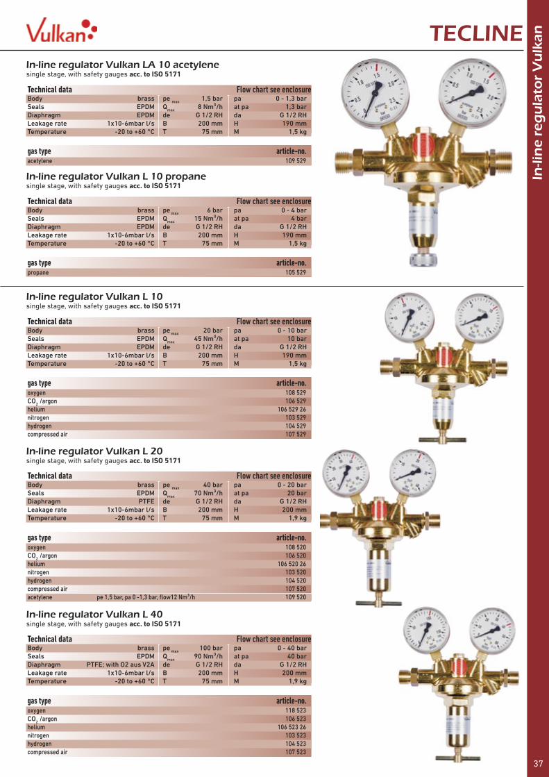
37
In-li
ne
reg
ula
tor
Vu
lkanTECLINE
In-line regulator Vulkan LA 10 acetylenesingle stage, with safety gauges acc. to ISO 5171
In-line regulator Vulkan L 10 propanesingle stage, with safety gauges acc. to ISO 5171
In-line regulator Vulkan L 10single stage, with safety gauges acc. to ISO 5171
In-line regulator Vulkan L 20single stage, with safety gauges acc. to ISO 5171
In-line regulator Vulkan L 40single stage, with safety gauges acc. to ISO 5171
Technical data Flow chart see enclosureBody brass pe max 1,5 bar pa 0 - 1,3 barSeals EPDM Qmax 8 Nm³/h at pa 1,3 barDiaphragm EPDM de G 1/2 RH da G 1/2 RHLeakage rate 1x10⁻⁶mbar l/s B 200 mm H 190 mmTemperature -20 to +60 °C T 75 mm M 1,5 kg
Technical data Flow chart see enclosureBody brass pe max 6 bar pa 0 - 4 barSeals EPDM Qmax 15 Nm³/h at pa 4 barDiaphragm EPDM de G 1/2 RH da G 1/2 RHLeakage rate 1x10⁻⁶mbar l/s B 200 mm H 190 mmTemperature -20 to +60 °C T 75 mm M 1,5 kg
Technical data Flow chart see enclosureBody brass pe max 20 bar pa 0 - 10 barSeals EPDM Qmax 45 Nm³/h at pa 10 barDiaphragm EPDM de G 1/2 RH da G 1/2 RHLeakage rate 1x10⁻⁶mbar l/s B 200 mm H 190 mmTemperature -20 to +60 °C T 75 mm M 1,5 kg
Technical data Flow chart see enclosureBody brass pe max 40 bar pa 0 - 20 barSeals EPDM Qmax 70 Nm³/h at pa 20 barDiaphragm PTFE de G 1/2 RH da G 1/2 RHLeakage rate 1x10⁻⁶mbar l/s B 200 mm H 200 mmTemperature -20 to +60 °C T 75 mm M 1,9 kg
Technical data Flow chart see enclosureBody brass pe max 100 bar pa 0 - 40 barSeals EPDM Qmax 90 Nm³/h at pa 40 barDiaphragm PTFE; with O2 aus V2A de G 1/2 RH da G 1/2 RHLeakage rate 1x10⁻⁶mbar l/s B 200 mm H 200 mmTemperature -20 to +60 °C T 75 mm M 1,9 kg
gas type article-no.acetylene 109 529
gas type article-no.propane 105 529
gas type article-no.oxygen 108 529CO2 /argon 106 529helium 106 529 26nitrogen 103 529hydrogen 104 529compressed air 107 529
gas type article-no.oxygen 118 523CO2 /argon 106 523helium 106 523 26nitrogen 103 523hydrogen 104 523compressed air 107 523
gas type article-no.oxygen 108 520CO2 /argon 106 520helium 106 520 26nitrogen 103 520hydrogen 104 520compressed air 107 520acetylene pe 1,5 bar, pa 0 -1,3 bar, flow12 Nm³/h 109 520

38
In-li
ne
reg
ula
tor
Vu
lkan TECLINE
In-line regulator Vulkan LR 20single stage, with safety gauges acc. to ISO 5171
In-line regulator Vulkan LR 40single stage, with safety gauges acc. to ISO 5171
In-line regulator Vulkan LR 60single stage, with safety gauges acc. to ISO 5171
Technical data Flow chart see enclosureBody brass pe max 40 bar pa 0 - 20 barSeals polyamide Qmax 160 Nm³/h at pa 20 barDiaphragm rubber de G 3/4 RH da G 3/4 RHLeakage rate 1x10⁻⁶mbar l/s B 240 mm H 240 mmTemperature -20 to +60 °C T 85 mm M 3 kg
Technical data Flow chart see enclosureBody brass pe max 100 bar pa 15 - 40 barSeals polyamide Qmax 280 Nm³/h at pa 40 barDiaphragm rubber, with O2 VA de G 3/4 RH da G 3/4 RHLeakage rate 1x10⁻⁶mbar l/s B 240 mm H 330 mmTemperature -20 to +60 °C T 85 mm M 3,8 kg
Technical data Flow chart see enclosureBody brass pe max 100 bar pa 15 - 60 barSeals polyamide Qmax 370 Nm³/h at pa 60 barDiaphragm rubber, with O2 VA de G 3/4 RH da G 3/4 RHLeakage rate 1x10⁻⁶mbar l/s B 240 mm H 330 mmTemperature -20 to +60 °C T 85 mm M 3,8 kg
gas type article-no.oxygen 108 525CO2 /argon 106 525helium 106 525 26nitrogen 103 525hydrogen 104 525compressed air 107 525propane, pe 6 bar, pa 0 - 4 bar, flow 25 Nm³/h 105 525
gas type article-no.oxygen 118 545CO2 /argon 106 545helium 106 545 26nitrogen 103 545hydrogen 104 545compressed air 107 545
gas type article-no.oxygen 118 565CO2 /argon 106 565helium 106 565 26nitrogen 103 565hydrogen 104 565compressed air 107 565
In-line regulator Vulkan L 15/2double stage, with safety gauges acc. to ISO 5171
Technical data Flow chart see enclosureBody brass pe max 20 bar pa 0 - 1,5 barSeals polyamide Qmax 5 Nm³/h at pa 1,5 barDiaphragm EPDM de G 1/2 RH da G 1/2 RHLeakage rate 1x10⁻⁶mbar l/s B 220 mm H 190 mmTemperature -20 to +60 °C T 75 mm M 2,0 kg
gas type article-no.oxygen 108 564CO2 /argon 106 564helium 106 564 26nitrogen 103 564hydrogen 104 564compressed air 107 564

39
In-li
ne
reg
ula
tor
Vu
lkanTECLINE
In-line regulator Vulkan LH 25/10single stage, with safety gauge acc. to ISO 5171, like LH 25, but owrking pressure adjustable 0 - 10 bar
Technical data Flow chart see enclosureBody brass pe max 40 bar pa 0 - 10 barSeals NBR Qmax 180 Nm³/h at pa 10 barDiaphragm NBR de G 1 RH da G 1 RHLeakage rate 1x10⁻³mbar l/s B 200 mm H 240 mmTemperature -20 to +60 °C T 145 mm M 3,6 kg
gas type article-no.oxygen 108 511 10CO2 /argon 106 511 10helium 106 511 26 10nitrogen 103 511 10hydrogen 104 511 10compressed air 107 511 10
In-line regulator Vulkan LH 25single stage, with safety gauge acc. to ISO 5171
Technical data Flow chart see enclosureBody brass pe max 40 bar pa 0 - 25 barSeals NBR Qmax 300 Nm³/h at pa 25 barDiaphragm NBR de G 1 da G 1Leakage rate 1x10⁻³mbar l/s B 200 mm H 210 mmTemperature -20 to +60 °C T 120 mm M 3,6 kg
gas type article-no.oxygen 108 511CO2 /argon 106 511helium 106 511 26nitrogen 103 511hydrogen 104 511compressed air 107 511
In-line regulator Vulkan LH 40single stage, with safety gauge acc. to ISO 5171, for high flow and high performance
Technical data Flow chart see enclosureBody brass pe max 40 bar pa see belowSeals Perbunan Qmax see below at pa see belowDiaphragm NBR de G 1/2 RH da G 1/2 RHLeakage rate 1x10⁻³mbar l/s B 90 mm H 180 mmTemperature -20 to +60 °C T 90 mm M 1,3 kg
gas type outlet pressure flow article-no.oxygen 0,2 – 4 bar 30 Nm³/h 108 530 04CO2 /argon 106 530 04helium 106 530 26 04nitrogen 103 530 04hydrogen 104 530 04compressed air 107 530 04oxygen 0,2 – 10 bar 105 Nm³/h 108 530 10CO2 /argon 106 530 10helium 106 530 26 10nitrogen 103 530 10hydrogen 104 530 10compressed air 107 530 10oxygen 0,2 – 20 bar 170 Nm³/h 108 530 20CO2 /argon 106 530 20helium 106 530 26 20nitrogen 103 530 20hydrogen 104 530 20compressed air 107 530 20oxygen 0,2 – 35 bar 230 Nm³/h 108 530 35CO2 /argon 106 530 35helium 106 530 26 35nitrogen 103 530 35hydrogen 104 530 35compressed air 107 530 35
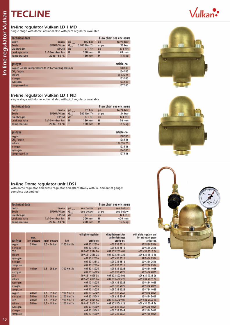
40
In-li
ne
reg
ula
tor
Vu
lkan TECLINE
In-line regulator Vulkan LD 1 MDsingle stage with dome, optional also with pilot regulator available
In-line regulator Vulkan LD 1 NDsingle stage with dome, optional also with pilot regulator available
Technical data Flow chart see enclosureBody brass pe max 100 bar pa to 99 barSeals EPDM/Viton Qmax 2.400 Nm³/h at pa 99 barDiaphragm EPDM de G 1 RH da G 1 RHLeakage rate 1x10⁻⁶mbar l/s B 130 mm H 170 mmTemperature -20 to +60 °C T 130 mm M 11,5 kg
Technical data Flow chart see enclosureBody brass pe max 25 bar pa to 24 barSeals EPDM/Viton Qmax 280 Nm³/h at pa 24 barDiaphragm EPDM de G 1 RH da G 1 RHLeakage rate 1x10⁻⁶mbar l/s B 130 mm H 170 mmTemperature -20 to +60 °C T 130 mm M 11,5 kg
gas type article-no.oxygen 40 bar inlet pressure, to 39 bar working pressure 108 535CO2 /argon 106 535helium 106 535 26nitrogen 103 535hydrogen 104 535compressed air 107 535
gas type article-no.oxygen 108 536CO2 /argon 106 536helium 106 536 26nitrogen 103 536hydrogen 104 536compressed air 107 536
In-line Dome regulator unit LDS1 with dome regulator and pilote regulator and alternatively with in- and outlet gauge; complete assembled
Technical data Flow chart see enclosureBody brass pe max see below pa see belowSeals EPDM/Viton Qmax see below at pa see belowDiaphragm EPDM de G 1 RH da G 1 RHLeakage rate 1x10⁻⁶mbar l/s B 200 mm H 400 mmTemperature -20 to +60 °C T 200 mm M 13,5 kg
with pilote regulator with pilote regulator with pilote regulator and max. and outlet gauge in- and outlet gaugegas type inlet pressure outlet pressure flow article-no. article-no. article-no.oxygen 25 bar 0,5 – 16 bar 1.100 Nm³/h 409 831 2516 409 833 2516 409 834 2516inert gas 409 631 2516 409 633 2516 409 634 2516CO2 409 631 2516 06 409 633 2516 06 409 634 2516 06helium 409 631 2516 26 409 633 2516 26 409 634 2516 26hydrogen 409 431 2516 409 433 2516 409 434 2516nitrogen 409 331 2516 409 333 2516 409 334 2516compr. air 409 731 2516 409 733 2516 409 734 2516oxygen 40 bar 0,5 – 25 bar 1.700 Nm³/h 409 831 4025 409 833 4025 409 834 4025inert gas 409 631 4025 409 633 4025 409 634 4025CO2 409 631 4025 06 409 633 4025 06 409 634 4025 06helium 409 631 4025 26 409 633 4025 26 409 634 4025 26hydrogen 409 431 4025 409 433 4025 409 434 4025nitrogen 409 331 4025 409 333 4025 409 334 4025compr. air 409 731 4025 409 733 4025 409 734 4025oxygen 40 bar 0,5 – 39 bar 1.900 Nm³/h 409 831 4049 409 833 4049 409 834 4049inert gas 50 bar 0,5 – 49 bar 2.100 Nm³/h 409 631 5049 409 633 5049 409 634 5049CO2 40 bar 0,5 – 39 bar 1.900 Nm³/h 409 631 4049 06 409 633 4049 06 409 634 4049 06helium 50 bar 0,5 – 49 bar 2.100 Nm³/h 409 631 5049 26 409 633 5049 26 409 634 5049 26hydrogen 409 431 5049 409 433 5049 409 434 5049nitrogen 409 331 5049 409 333 5049 409 334 5049compr. air 409 731 5049 409 733 5049 409 734 5049

41
In-li
ne
reg
ula
tor
Vu
lkanTECLINE
Precision-In-line regulator Vulkan LP 216-0.6single stage, with safety gauge
Precision-In-line regulator Vulkan LP 216-1.6single stage, with safety gauge
Technical data Flow chart see enclosureBody aluminium, zinc diecasting pe max 21 bar pa 0,01 - 0,6 barSeals NBR Qmax 45 Nm³/h at pa 0,6 barDiaphragm NBR de G 3/8 RH da G 3/8 RHLeakage rate 1x10⁻⁶mbar l/s B 108 mm H 162 mmTemperature -20 to +60 °C T 108 mm M 2,0 kg
Technical data Flow chart see enclosureBody aluminium, zinc diecasting pe max 21 bar pa 0,01 - 1,6 barSeals NBR Qmax 50 Nm³/h at pa 1,6 barDiaphragm NBR de G 3/8 RH da G 3/8 RHLeakage rate 1x10⁻⁶mbar l/s B 108 mm H 162 mmTemperature -20 to +60 °C T 108 mm M 2,0 kg
gas type article-no.oxygen 108 512CO2 /argon 106 512helium 106 512 26nitrogen 103 512hydrogen 104 512compressed air 107 512
gas type article-no.oxygen 108 512 01CO2 /argon 106 512 01helium 106 512 26 01nitrogen 103 512 01hydrogen 104 512 01compressed air 107 512 01
In-line regulator Vulkan LH 119-1single stage, with safety gauge
Technical data Flow chart see enclosureBody zinc die cast/brass pe max 21 bar pa 0,2 – 1,8 barSeals NBR Qmax 150 Nm³/h at pa 1,8 barDiaphragm NBR de G ½ RH da G ½ RHLeakage rate 1x10⁻⁶mbar l/s B 90 mm H 175 mmTemperature -20 to +60 °C T 90 mm M 1,6 kg
gas type article-no.oxygen max. 10 bar inlet pressure 108 410CO2 /argon 106 410helium 106 410 26nitrogen 103 410hydrogen 104 410compressed air 107 410
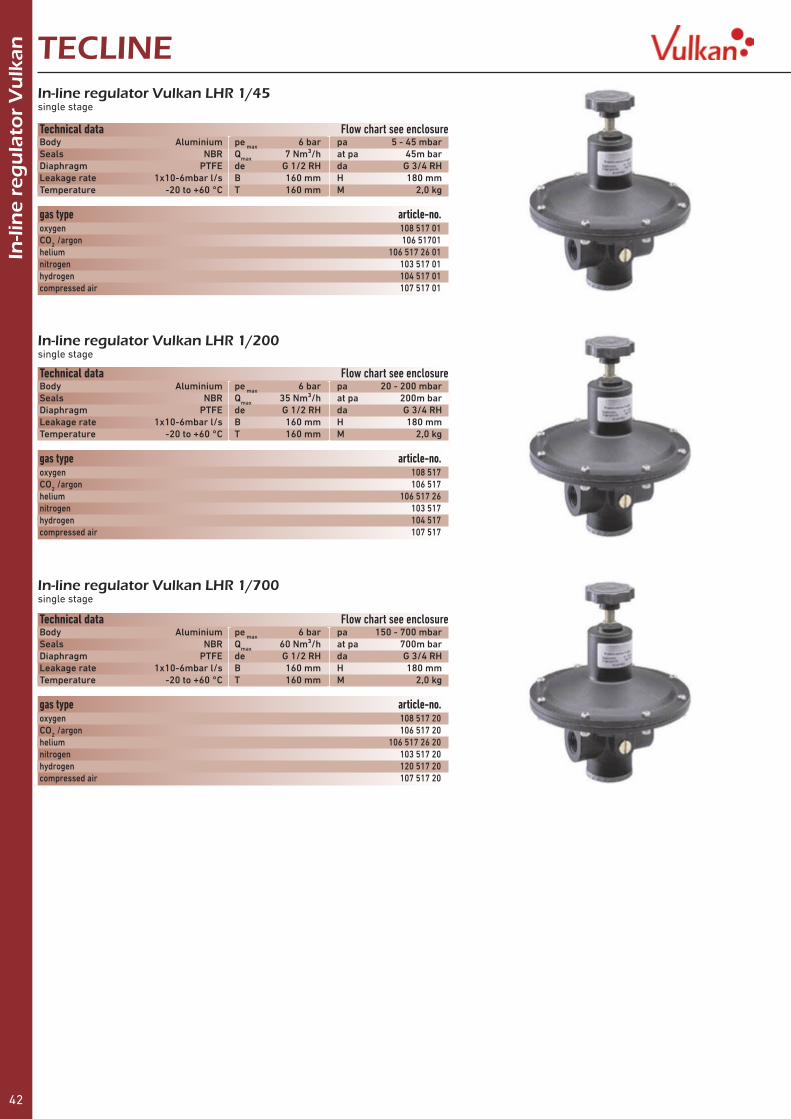
42
TECLINEIn
-lin
e re
gu
lato
r V
ulk
an
In-line regulator Vulkan LHR 1/200single stage
In-line regulator Vulkan LHR 1/45single stage
In-line regulator Vulkan LHR 1/700single stage
Technical data Flow chart see enclosureBody Aluminium pe max 6 bar pa 20 - 200 mbarSeals NBR Qmax 35 Nm³/h at pa 200m barDiaphragm PTFE de G 1/2 RH da G 3/4 RHLeakage rate 1x10⁻⁶mbar l/s B 160 mm H 180 mmTemperature -20 to +60 °C T 160 mm M 2,0 kg
Technical data Flow chart see enclosureBody Aluminium pe max 6 bar pa 5 - 45 mbarSeals NBR Qmax 7 Nm³/h at pa 45m barDiaphragm PTFE de G 1/2 RH da G 3/4 RHLeakage rate 1x10⁻⁶mbar l/s B 160 mm H 180 mmTemperature -20 to +60 °C T 160 mm M 2,0 kg
Technical data Flow chart see enclosureBody Aluminium pe max 6 bar pa 150 - 700 mbarSeals NBR Qmax 60 Nm³/h at pa 700m barDiaphragm PTFE de G 1/2 RH da G 3/4 RHLeakage rate 1x10⁻⁶mbar l/s B 160 mm H 180 mmTemperature -20 to +60 °C T 160 mm M 2,0 kg
gas type article-no.oxygen 108 517CO2 /argon 106 517helium 106 517 26nitrogen 103 517hydrogen 104 517compressed air 107 517
gas type article-no.oxygen 108 517 01CO2 /argon 106 51701helium 106 517 26 01nitrogen 103 517 01hydrogen 104 517 01compressed air 107 517 01
gas type article-no.oxygen 108 517 20CO2 /argon 106 517 20helium 106 517 26 20nitrogen 103 517 20hydrogen 120 517 20compressed air 107 517 20

43
TECLINE
Pre
ssu
re r
egu
lato
r V
ulk
an a
cc. t
o IS
O 2
50
3
Vulkan Effect with high pressure compensationfor constant working pressure at all working conditions
Without high pressure compensation As the cylinder pressure decreases, the working pressure increases.The consumption of gas will increase with 300 bar up to more than 50 %With high pressure compensationAs the cylinder pressure decreases, the working pressure will remain constant and so does your gas consumption you realise significant gas savings!
300 bar gas cylinders intensify enormously the effect of increase of working pressure, while the cylinder pressure is decreasing. It is even more important to use a pressure regulator with high pressure compensation than with 200 bar gas cylinders.Therefore all pressure regulators Vulkan have the integrated high pressure compensation Effect to provide you an optimal working performance and safety.
Pressure regulator Vulkan F 10/300 Effectsingle stage, acc. to ISO 2503, for oxygen and acetylene BAM-approved
Pressure regulator Vulkan F10/200 standard single stage, acc. to ISO 2503, but without high pressure compensation,for oxygen BAM-approved
Technical data Flow chart see enclosureBody brass pe max 200/300 bar pa 0 - 10 barSeals polyamide, EPDM Qmax see below at pa see belowDiaphragm EPDM de see below da see belowLeakage rate 1x10⁻⁶mbar l/s B 210 mm H 190 mmTemperature -20 to +60 °C T 75 mm M 1,5 kg
gas type inlet pressure pressure flow inlet outlet art.-no.oxygen 200 bar 0 - 10 bar 46 Nm³/h G3/4RH nut G 1/4 RH x 6 mm 208 100acetylene 20 bar 0 - 1,5 bar 3,5 Nm³/h clamp G 3/8 LH x 9 mm 209 000CO2 /argon 200 bar 0 - 10 bar 46 Nm³/h W21,8x1/14RH nut G 1/4 RH x 6 mm 226 005helium ” ” ” ” ” 226 025nitrogen ” ” ” W24,32x1/14RH nut ” 203 005hydrogen ” ” ” W21,8x1/14LH nut G 3/8 LH x 9 mm 204 005forming gas ” ” ” ” ” 204 805 ” 0 - 30 Nl/min. 1,8 Nm³/h ” ” 204 835 ” 0 - 50 Nl/min. 3,0 Nm³/h ” ” 204 855compressed air ” 0 - 10 bar 46 Nm³/h G 5/8 RH G 1/4 RH x 6 mm 207 005testing gas ” ” ” M19x1,5LH nut G 3/8 LH x 9 mm 203 805nitrous oxide 80 bar ” ” G 3/8 RH nut G 1/4 RH x 6 mm 203 061methane 200 bar ” ” W21,8x1/14LH nut G 3/8 LH x 9 mm 205 676oxygen 300 bar 0 - 10 bar 46 Nm³/h W 30x2RH nut G 1/4 RH x 6 mm 308 100CO2 /argon ” ” ” ” ” 326 005 ” 0 - 20 Nl/min. 1,2 Nm³/h ” ” 326 105 ” 0 - 30 Nl/min. 1,8 Nm³/h ” ” 326 130helium ” 0 - 10 bar 46 Nm³/h ” ” 326 025nitrogen ” 0 - 10 bar ” ” ” 303 005hydrogen ” ” ” W 30x2LH nut G 3/8 LH x 9 mm 304 005forming gas ” ” ” ” ” 304 805 ” 0 - 30 Nl/min. 1,8 Nm³/h ” ” 304 835 ” 0 - 50 Nl/min. 3,0 Nm³/h ” ” 304 855compressed air ” 0 - 10 bar 46 Nm³/h W 30x2RH nut G 1/4 RH x 6 mm 307 005testing gas ” ” ” W 30x2LH nut G 3/8 LH x 9 mm 303 805
gas type inlet pressure pressure flow inlet outlet art.-no.oxygen 200 bar 0 - 10 bar 46 Nm³/h G3/4RH nut G 1/4 RH x 6 mm 208 000CO2 /argon 200 bar „ „ W21,8x1/14RH nut „ 226 000 „ 0 - 20 Nl/min. 1,2 Nm³/h „ „ 226 100 „ 0 - 30 Nl/min. 1,8 Nm³/h „ „ 226 125helium „ 0 - 10 bar 46 Nm³/h „ „ 226 020nitrogen „ „ „ W24,32x1/14RH nut „ 203 000hydrogen „ „ „ W21,8x1/14LH nut G 3/8 LH x 9 mm 204 000forming gas „ „ „ „ „ 204 800 „ 0 - 30 Nl/min. 1,8 Nm³/h „ „ 204 830 „ 0 - 50 Nl/min. 3,0 Nm³/h „ „ 204 850compressed air „ 0 - 10 bar 46 Nm³/h G 5/8 RH G 1/4 RH x 6 mm 207 000testing gas „ „ „ M19x1,5LH Üm G 3/8 LH x 9 mm 203 800nitrous oxide 80 bar „ „ G 3/8 RH nut G 1/4 RH x 6 mm 203 060propane 8 bar 0 - 4 bar 5 kg/h W21,8x1/14LH nut G 3/8 LH x 9 mm 205 600ethene 80 bar 0 - 1,5 bar 3,5 Nm³/h „ „ 205 625methane 200 bar 0 - 10 bar 46 Nm³/h „ „ 205 675
38
Pre
ssu
re r
egu
lato
r V
ulk
an a
cc. t
o IS
O 2
50
3 TECLINEVulkan Effect with high pressure compensationfor constant working pressure at all working conditions
Without high pressure compensation As the cylinder pressure decreases, the working pressure increases.The consumption of gas will increase with 300 bar up to more than 50 %With high pressure compensationAs the cylinder pressure decreases, the working pressure willremain constant and so does your gas consumption you realise signifi cant gas savings!
300 bar gas cylinders intensify enormously the effect of increase of working pressure, while the cylinder pressure is decreasing. It is even more important to use a pressure regulator with high pressure compensation than with 200 bar gas cylinders.Therefore all pressure regulators Vulkan have the integrated high pressure compensation Effect to provide you an optimal working performance and safety.
Pressure regulator Vulkan F 10/300 Effectsingle stage, acc. to ISO 2503, for oxygen and acetylene BAM-approved
Pressure regulator Vulkan F10/200 standard single stage, acc. to ISO 2503, but without high pressure compensation,for oxygen BAM-approved
Technical data Flow chart see enclosureBody brass pe max 200/300 bar pa 0 - 10 barSeals polyamide, EPDM Qmax see below at pa see belowDiaphragm EPDM de see below da see belowLeakage rate 1x10⁻⁶mbar l/s B 210 mm H 190 mmTemperature -20 to +60 °C T 75 mm M 1,5 kg
gas type inlet pressure pressure fl ow inlet outlet art.-no.oxygen 200 bar 0 - 10 bar 46 Nm³/h G3/4RH nut G 1/4 RH x 6 mm 208 100acetylene 20 bar 0 - 1,5 bar 3,5 Nm³/h clamp G 3/8 LH x 9 mm 209 000CO2 /argon 200 bar 0 - 10 bar 46 Nm³/h W21,8x1/14RH nut G 1/4 RH x 6 mm 226 005helium ” ” ” ” ” 226 025nitrogen ” ” ” W24,32x1/14RH nut ” 203 005hydrogen ” ” ” W21,8x1/14LH nut G 3/8 LH x 9 mm 204 005forming gas ” ” ” ” ” 204 805 ” 0 - 30 Nl/min. 1,8 Nm³/h ” ” 204 835 ” 0 - 50 Nl/min. 3,0 Nm³/h ” ” 204 855compressed air ” 0 - 10 bar 46 Nm³/h G 5/8 RH G 1/4 RH x 6 mm 207 005testing gas ” ” ” M19x1,5LH nut G 3/8 LH x 9 mm 203 805nitrous oxide 80 bar ” ” G 3/8 RH nut G 1/4 RH x 6 mm 203 061methane 200 bar ” ” W21,8x1/14LH nut G 3/8 LH x 9 mm 205 676oxygen 300 bar 0 - 10 bar 46 Nm³/h W 30x2RH nut G 1/4 RH x 6 mm 308 100CO2 /argon ” ” ” ” ” 326 005 ” 0 - 20 Nl/min. 1,2 Nm³/h ” ” 326 105 ” 0 - 30 Nl/min. 1,8 Nm³/h ” ” 326 130helium ” 0 - 10 bar 46 Nm³/h ” ” 326 025nitrogen ” 0 - 10 bar ” ” ” 303 005hydrogen ” ” ” W 30x2LH nut G 3/8 LH x 9 mm 304 005forming gas ” ” ” ” ” 304 805 ” 0 - 30 Nl/min. 1,8 Nm³/h ” ” 304 835 ” 0 - 50 Nl/min. 3,0 Nm³/h ” ” 304 855compressed air ” 0 - 10 bar 46 Nm³/h W 30x2RH nut G 1/4 RH x 6 mm 307 005testing gas ” ” ” W 30x2LH nut G 3/8 LH x 9 mm 303 805
gas type inlet pressure pressure fl ow inlet outlet art.-no.oxygen 200 bar 0 - 10 bar 46 Nm³/h G3/4RH nut G 1/4 RH x 6 mm 208 000CO2 /argon 200 bar ” ” W21,8x1/14RH nut ” 226 000 ” 0 - 20 Nl/min. 1,2 Nm³/h ” ” 226 100 ” 0 - 30 Nl/min. 1,8 Nm³/h ” ” 226 125helium ” 0 - 10 bar 46 Nm³/h ” ” 226 020nitrogen ” ” ” W24,32x1/14RH nut ” 203 000hydrogen ” ” ” W21,8x1/14LH nut G 3/8 LH x 9 mm 204 000forming gas ” ” ” ” ” 204 800 ” 0 - 30 Nl/min. 1,8 Nm³/h ” ” 204 830 ” 0 - 50 Nl/min. 3,0 Nm³/h ” ” 204 850compressed air ” 0 - 10 bar 46 Nm³/h G 5/8 RH G 1/4 RH x 6 mm 207 000testing gas ” ” ” M19x1,5LH nut G 3/8 LH x 9 mm 203 800nitrous oxide 80 bar ” ” G 3/8 RH nut G 1/4 RH x 6 mm 203 060propane 8 bar 0 - 4 bar 5 kg/h W21,8x1/14LH nut G 3/8 LH x 9 mm 205 600ethene 80 bar 0 - 1,5 bar 3,5 Nm³/h ” ” 205 625methane 200 bar 0 - 10 bar 46 Nm³/h ” ” 205 675
Vulkan2013_28-39_TecLine_Vulkan_eng.indd 38 21.07.13 15:57

44
TECLINEP
ress
ure
reg
ula
tor
Vu
lkan
acc
. to
ISO
25
03
Pressure regulator Vulkan F 20/300 Effectsingle stage, acc. to ISO 2503, working pressure adjustable to 20 bar
Pressure regulator Vulkan F 60/300 Effectflow up to 140 Nm3/h as Pressure regulator Vulkan F20 Effect, but working pressure adjustable to 60 bar and without shut off valve
Pressure regulator Vulkan F 40/300 Effectflow up to 120 Nm3/h as Pressure regulator Vulkan F20 Effect, but working pressure adjustable to 40 bar
Technical data Flow chart see enclosureBody brass pe max 200/300 bar pa 0 - 20 barSeals EPDM, polyamide Qmax 75 Nm³/h at pa 20 barDiaphragm PTFE de see below da see belowLeakage rate 1x10⁻⁶mbar l/s B 210 mm H 210 mmTemperature -20 to +60 °C T 75 mm M 1,9 kg
gas type inlet pressure pressure inlet outlet art.-no.oxygen 200 bar 0 - 20 bar G3/4RH nut G 1/4 RH x 6 mm 208 300CO2 /argon ” ” W21,8x1/14RH nut ” 206 300helium ” ” ” ” 206 326nitrogen ” ” W24,32x1/14RH ” 203 300hydrogen ” ” W21,8x1/14LH G 3/8 LH x 9 mm 204 300forming gas ” ” ” ” 204 380compressed air ” ” G 5/8 RH G 1/4 RH x 6 mm 207 300testing gas ” ” M19x1,5LH G 3/8 LH x 9 mm 203 380methane ” ” W21,8x1/14LH ” 204 320oxygen 300 bar 0 - 20 bar W 30x2RH nut G 1/4 RH x 6 mm 308 300CO2 /argon ” ” ” ” 306 300helium ” ” ” ” 306 326nitrogen ” ” ” ” 303 300hydrogen ” ” W 30x2LH nut G 3/8 LH x 9 mm 304 300forming gas ” ” ” ” 304 380compressed air ” ” W 30x2RH nut G 1/4 RH x 6 mm 307 300testing gas ” ” W 30x2LH nut G 3/8 LH x 9 mm 303 380
gas type inlet pressure pressure inlet outlet art.-no.CO2 /argon 200 bar 0 - 40 bar W21,8x1/14RH nut G 1/4 RH x 6 mm 206 350helium ” ” ” ” 206 376nitrogen ” ” W24,32x1/14RH ” 203 350hydrogen ” ” W21,8x1/14LH G 3/8 LH x 9 mm 204 350forming gas ” ” ” ” 204 383compressed air ” ” G 5/8 RH G 1/4 RH x 6 mm 207 350testing gas ” ” M19x1,5LH G 3/8 LH x 9 mm 203 383methane ” ” W21,8x1/14LH ” 204 323CO2 /argon 300 bar 0 - 40 bar W30x2RH nut G 1/4 RH x 6 mm 306 350helium ” ” ” ” 306 376nitrogen ” ” ” ” 303 350hydrogen ” ” W30x2LH nut G 3/8 LH x 9 mm 304 350forming gas ” ” ” ” 304 383compressed air ” ” W30x2RH nut G 1/4 RH x 6 mm 307 350testing gas ” ” W30x2LH nut G 3/8 LH x 9 mm 303 383
gas type inlet pressure pressure inlet outlet art.-no.CO2 /argon 200 bar 0 – 60 bar W21,8x1/14RH nut G 1/4 RH 206 375helium ” ” ” ” 206 375 26nitrogen ” ” W24,32x1/14RH ” 203 375hydrogen ” ” W21,8x1/14LH G 3/8 LH 204 375forming gas ” ” ” ” 204 384compressed air ” ” G 5/8 RH G 1/4 RH 207 375testing gas ” ” M19x1,5LH G 3/8 LH 203 384methane ” ” W21,8x1/14LH ” 204 324CO2 /argon 300 bar 0 – 60 bar W30x2RH nut G 1/4 RH 306 375helium ” ” ” ” 306 375 26nitrogen ” ” ” ” 303 375hydrogen ” ” W30x2LH nut G 3/8 LH 304 375forming gas ” ” ” ” 304 384compressed air ” ” W30x2RH nut G 1/4 RH 307 375testing gas ” ” W30x2LH nut G 3/8 LH 303 384

45
CO2 /argon 0,9 - 5,0 Nl/min. 4,0 bar W 30x2RH nut G 1/4 RH x 6 mm 326 403 1,0 - 14,0 Nl/min. 1,5 bar ” ” 326 405 2,5 - 23,0 Nl/min. ” ” ” 326 425 4,0 - 32,0 Nl/min. ” ” ” 326 455 10,0 - 95,0 Nl/min. 9 bar ” ” 326 475helium 3,0 - 34,0 Nl/min. 1,5 bar ” ” 326 795 5, 0 - 60,0 Nl/min. ” ” ” 326 797nitrogen 0,3 - 2,0 Nl/min. ” ” ” 323 610 4,0 - 42 Nl/min. 1,5 bar ” ” 323 615 8,0 - 80,0 Nl/min. 4,0 bar ” ” 323 616hydrogen 1,7 - 17,0 Nl/min. 1,5 bar W 30x2LH nut G 3/8 LH x 9 mm 324 600 2,6 - 26 Nl/min. ” ” ” 324 605forming gas 2,0 - 23,0 Nl/min. ” ” ” 326 605
Pre
ssu
re r
egu
lato
r V
ulk
an a
cc. t
o IS
O 2
50
3TECLINEPressure regulator Vulkan F 15/300 Effectsingle stage, acc. to ISO 2503, working pressure adjustable 0 - 1,5 bar
Technical data Flow chart see enclosureBody brass pe max 200/300 bar pa 0 - 1,5 barSeals EPDM Qmax to 8 Nm³/h bei pa 1,5 barDiaphragm EPDM de see below da see belowLeakage rate 1x10⁻⁶mbar l/s B 210 mm H 190 mmTemperature -20 to +60 °C T 75 mm M 1,5 kg
gas type inlet pressure pressure inlet outlet art.-no.CO2 /argon 200 bar 0 - 1,5 bar W21,8x1/14RH nut G 1/4 RH x 6 mm 206 315helium ” ” ” ” 206 316nitrogen ” ” W24,32x1/14RH ” 203 315hydrogen ” ” W21,8x1/14LH G 3/8 LH x 9 mm 204 315forming gas ” ” ” ” 204 316compressed air ” ” G 5/8 RH G 1/4 RH x 6 mm 207 315testing gas ” ” M19x1,5LH G 3/8 LH x 9 mm 203 316methane ” ” W21,8x1/14LH ” 204317CO2 /argon 300 bar 0 - 1,5 bar W30x2RH nut G 1/4 RH x 6 mm 306 315helium ” ” ” ” 306 316nitrogen ” ” ” ” 303 315hydrogen ” ” W30x2LH nut G 3/8 LH x 9 mm 304 315forming gas ” ” ” ” 304 316compressed air ” ” W30x2RH nut G 1/4 RH x 6 mm 307 315testing gas ” ” W30x2LH nut G 3/8 LH x 9 mm 303 316
Pressure regulator Vulkan F 10/300 F Effect with Flowmetersingle stage, acc. to ISO 2503, with high pressure compensation Effect for constant working pressure at all working conditions, he flowmeter enables the adjustment of a certain flow at constant working pressure
gas type inlet 200 bar pressure inlet outlet art.-no. flow rangeCO2 /argon 0,9 - 5,0 Nl/min. 4,0 bar W21,8x1/14RH nut G 1/4 RH x 6 mm 226 403 1,0 - 14,0 Nl/min. 1,5 bar ” ” 226 405 2,5 - 23,0 Nl/min. ” ” ” 226 425 4,0 - 32,0 Nl/min. ” ” ” 226 455 10,0 - 95,0 Nl/min. 9 bar ” ” 226 475helium 3,0 - 34,0 Nl/min. 1,5 bar ” ” 226 795 5, 0 - 60,0 Nl/min. ” ” ” 226 797nitrogen 0,3 - 2,0 Nl/min. ” W24,32x1/14RH ” 223 610 4,0 - 42 Nl/min. 1,5 bar ” ” 223 615 8,0 - 80,0 Nl/min. 4,0 bar ” ” 223 616hydrogen 1,7 - 17,0 Nl/min. 1,5 bar W21,8x1/14LH G 3/8 LH x 9 mm 224 600 2,6 - 26 Nl/min. ” ” ” 224 605forming gas 2,0 - 23,0 Nl/min. ” ” ” 226 605
Technical data Body brass pe max 200/300 bar pa see belowSeals polyamide, EPDM Qmax see below bei pa see belowDiaphragm EPDM de see below da see belowLeakage rate 1x10⁻⁶mbar l/s B 210 mm H 230 mmTemperature -20 to +60 °C T 75 mm M 1,5 kg
gas type inlet 300 bar pressure inlet outlet art.-no. flow range

46
Pre
ssu
re r
egu
lato
r V
ulk
an a
cc. t
o IS
O 2
50
3 TECLINEPressure regulator Vulkan F 15/300 2F Effect with 2 flow metersas Pressure regulator Vulkan F 10/300 F Effect with Flowmeter but with 2 flowmeters for two independent working processes
gas type inlet 200 bar pressure inlet outlet art.-no. flow range 2 x
gas type inlet 300 bar pressure inlet outlet art.-no. flow range 2 x
CO2/Argon 1,0 – 6,5 Nl/min. 4,0 bar W21,8x1/14RH nut G 1/4 RH x 6 mm 226 403 11 1,4 - 14,0 Nl/min. 1,5 bar „ „ 226 405 11 3,0 - 22,0 Nl/min. „ „ „ 226 425 11 3,6 - 36,0 Nl/min. „ „ „ 226 455 11 10,0 - 95,0 Nl/min. 9,0 bar „ „ 226 475 11helium 3,6 – 34,0 Nl/min. 1,5 bar „ „ 226 795 11 5, 0 - 65,0 Nl/min. „ „ „ 226 797 11nitrogen 0,3 - 2,0 Nl/min. „ W24,32x1/14RH „ 223 610 11 4,0 - 42 Nl/min. „ „ „ 223 615 11 8,5 - 85,0 Nl/min. 4,0 bar „ „ 223 616 11hydrogen 1,8 -18,0 Nl/min. 1,5 bar W21,8x1/14LH G 3/8 LH x 9 mm 224 600 11 2,6 - 26 Nl/min. „ „ „ 224 605 11forming gas 2,0 - 23,0 Nl/min. „ „ „ 226 605 11
CO2 / argon 1,0 – 6,5 Nl/min. 4,0 bar W 30x2RH nut G 1/4 RH x 6 mm 326 403 11 1,4 - 14,0 Nl/min. 1,5 bar „ „ 326 405 11 3,0 - 22,0 Nl/min. „ „ „ 326 425 11 3,6 - 36,0 Nl/min. „ „ „ 326 455 11 10,0 - 95,0 Nl/min. 9,0 bar „ „ 326 475 11helium 3,6 – 34,0 Nl/min. 1,5 bar „ „ 326 795 11 5, 0 - 65,0 Nl/min. „ „ „ 326 797 11nitrogen 0,3 - 2,0 Nl/min. „ „ „ 323 610 11 4,0 - 42 Nl/min. „ „ „ 323 615 11 8,5 - 85,0 Nl/min. 4,0 bar „ „ 323 616 11hydrogen 1,8 -18,0 Nl/min. 1,5 bar W 30x2LH nut G 3/8 LH x 9 mm 324 600 11 2,6 - 26 Nl/min. „ „ „ 324 605 11forming gas 2,0 - 23,0 Nl/min. „ „ „ 326 605 11
Technical data Body brass pe max 200/300 bar pa see belowSeals polyamide, EPDM Qmax see below bei pa see belowDiaphragm EPDM de see below da see belowLeakage rate 1x10⁻⁶mbar l/s B 250 mm H 230 mmTemperature -20 to +60 °C T 130 mm M 2,0 kg
Pressure regulator Vulkan F 10/2 300 Effectdouble stage, acc. to ISO 2503, working pressure adjustable 0 - 10 bar
Technical data Flow chart see enclosureBody brass pe max 200/300 bar pa 0 - 10 barSeals EPDM, polyamide Qmax 48 Nm³/h bei pa 10 barDiaphragm EPDM de see below da see belowLeakage rate 1x10⁻⁶mbar l/s B 240 mm H 190 mmTemperature -20 to +60 °C T 75 mm M 2,0 kg
gas type inlet pressure pressure inlet outlet art.-no.oxygen 200 bar 0 - 10 bar G3/4RH nut G 1/4 RH x 6 mm 208 200CO2 /argon 200 bar ” W21,8x1/14RH nut ” 226 200helium ” ” ” ” 226 226nitrogen ” ” W24,32x1/14RH nut ” 203 200hydrogen ” ” W21,8x1/14LH nut G 3/8 LH x 9 mm 204 200forming gas ” ” ” ” 204 820compressed air ” ” G 5/8 RH G 1/4 RH x 6 mm 207 200testing gas ” ” M19x1,5LH nut G 3/8 LH x 9 mm 203 820oxygen 300 bar 0 - 10 bar W30x2RH nut G 1/4 RH x 6 mm 308 200CO2 /argon ” ” ” ” 326 200helium ” ” ” ” 326 226nitrogen ” ” ” ” 303 200hydrogen ” ” W30x2LH nut G 3/8 LH x 9 mm 304 200forming gas ” ” ” ” 304 820compressed air ” ” W30x2RH nut G 1/4 RH x 6 mm 307 200testing gas ” ” W30x2LH nut G 3/8 LH x 9 mm 303 820

47
Pre
ssu
re r
egu
lato
r V
ulk
an a
cc. t
o IS
O 2
50
3TECLINEPressure regulator Vulkan F 15/2 300 Effectas Pressure regulator Vulkan F 10/2 300 Effect but working pressure adjustable 0 - 1,5 bar
Technical data Flow chart see enclosureBody brass pe max 200/300 bar pa 0 – 1,5 barSeals EPDM, polyamide Qmax 8 Nm³/h bei pa 1,5 barDiaphragm EPDM de see below da see belowLeakage rate 1x10⁻⁶mbar l/s B 240 mm H 190 mmTemperature -20 to +60 °C T 75 mm M 2,0 kg
gas type inlet pressure pressure inlet outlet art.-no.oxygen 200 bar 0 – 1,5 bar G3/4RH nut G 1/4 RH x 6 mm 208 250CO2 /argon 200 bar ” W21,8x1/14RH nut ” 226 250helium ” ” ” ” 226 250 26nitrogen ” ” W24,32x1/14RH nut ” 203 250hydrogen ” ” W21,8x1/14LH nut G 3/8 LH x 9 mm 204 250forming gas ” ” ” ” 204 851compressed air ” ” G 5/8 RH G 1/4 RH x 6 mm 207 250testing gas ” ” M19x1,5LH nut G 3/8 LH x 9 mm 203 851oxygen 300 bar 0 – 1,5 bar W30x2RH nut G 1/4 RH x 6 mm 308 250CO2 /argon ” ” ” ” 326 250helium ” ” ” ” 326 250 26nitrogen ” ” ” ” 303 250hydrogen ” ” W30x2LH nut G 3/8 LH x 9 mm 304 250forming gas ” ” ” ” 304 851compressed air ” ” W30x2RH nut G 1/4 RH x 6 mm 307 250testing gas ” ” W30x2LH nut G 3/8 LH x 9 mm 303 851

48
A
cces
sori
es TECLINEGas pre-heater Vulkan GPH 200a patented system puts the heat, where it has to be: into the gas!For an efficient heat transfer, complete with plug 230 V/50 HzFor high pressure applications, especially for high output or low atmospheretemperatures, gas connections acc. to DIN 477, PN 300, 200 W
Technical data Body plastic P max 300 bar L 150 mmGasführung brass Voltage 230V 50Hz H 90 mmSeals EPDM/PTFE flow 200 W H 90 mmLeakage rate 1x10⁻⁶mbar l/s protection class IP 44 M 2,0 kgTemperature -20 to +60 °C approved with CE mark
gas type pressure inlet outlet article-no.oxygen 200 bar G 3/4 RH nut G 3/4 RHaf 450 208 G 3/4 RHaf G 3/4 RH nut 450 218inert gases ” W 21,8x1/14 RH nut W 21,8x1/14 RHaf 450 206 W 21,8x1/14 RHaf W 21,8x1/14 RH nut 450 216nitrogen ” W 24,32x1/14 RH nut W 24,32x1/14 RHaf 450 203nitrous oxide ” G 3/8RH nut G 3/8RHa 450 202oxygen 300 bar W 30 x 2 RH nut W 30 x 2 RHa 450 308 M24x1,5RH nut M24x1,5RHak 450 070 M24x1,5RHak M24x1,5RH nut 450 079inert gases ” W 30 x 2 RH nut W 30 x 2 RHa 450 306 M24x1,5RH nut M24x1,5RHak 450 072 M24x1,5RHak M24x1,5RH nut 450 071 G 1/4RHi G 1/4RHi 450 073 1/4RH NPT F 1/4RH NPT M 450 074 G 1/2RHk nut G 1/2RHak 450 080nitrogen ” W 30 x 2 RH nut W 30 x 2 RHa 450 303
This sketch shows the development of the temperature when using 1 cylinder argon with 1 fin regulator at a constant flow of 25 Nm³/h at 5 bar working pressure
Gas pre-heater Vulkan GPH 400as GPH 200, but power 400 W
Gas pre-heater Vulkan GPH 400 VAas GPH 400, gas line parts made from stainless steel
Technical data Body plastic P max 300 bar L 150 mmGasführung brass Voltage 230V 50Hz H 90 mmSeals EPDM/PTFE flow 400 W H 90 mmLeakage rate 1x10⁻⁶mbar l/s protection class IP 44 M 2,0 kgTemperature -20 to +60 °C approved with CE mark
Technical data Body plastic P max 300 bar L 150 mmGas line AlSi316L Voltage 230V 50Hz H 90 mmSeals EPDM/PTFE flow 200 W H 90 mmLeakage rate 1x10⁻⁶mbar l/s protection class IP 44 M 2,0 kgTemperature -20 to +60 °C approved with CE mark
gas type pressure inlet outlet article-no.
gas type pressure inlet outlet article-no.
oxygen 200 bar G 3/4 RH nut G 3/4 Rhaf 451 208 G 3/4 Rhaf G 3/4 RH nut 451 218inert gases „ W 21,8x1/14 RH nut W 21,8x1/14 Rhaf 451 206 W 21,8x1/14 Rhaf W 21,8x1/14 RH nut 451 216nitrogen „ W 24,32x1/14 RH nut W 24,32x1/14 Rhaf 451 203nitrous oxide „ G 3/8RG nut G 3/8RHa 451 202oxygen 300 bar W 30 x 2 RH nut W 30 x 2 Rha 451 308 M 24x1,5 RH nut M 24x1,5 RHak 451 070 M 24x1,5 RHak M 24x1,5 RH nut 451 079inert gases „ W 30 x 2 RH nut W 30 x 2 Rha 451 306 M 24x1,5 RH nut M 24x1,5 RHak 451 072 M 24x1,5 RHak M 24x1,5 RH nut 451 071 G 1/4 RHi G 1/4 RHi 451 073 1/4 RH NPT F 1/4 RH NPT M 451 074 G 1/2 RHk nut G 1/2 RHak 451 080nitrogen „ W 30 x 2 RH W 30 x 2 Rha 451 303
inert gases 300 bar G 1/4 RH NPT F G 1/4 RH NPT F 457 074 03
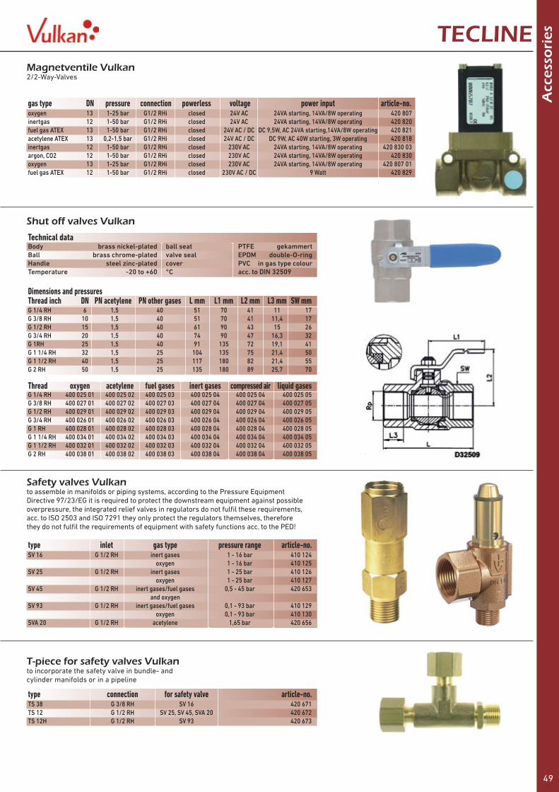
49
A
cces
sori
esTECLINE
Shut off valves Vulkan
Technical data Body brass nickel-plated ball seat PTFE gekammertBall brass chrome-plated valve seal EPDM double-O-ringHandle steel zinc-plated cover PVC in gas type colourTemperature -20 to +60 °C acc. to DIN 32509
Magnetventile Vulkan2/2-Way-Valves
gas type DN pressure connection powerless voltage power input article-no.oxygen 13 1-25 bar G1/2 RHi closed 24V AC 24VA starting, 14VA/8W operating 420 807inertgas 12 1-50 bar G1/2 RHi closed 24V AC 24VA starting, 14VA/8W operating 420 820fuel gas ATEX 13 1-50 bar G1/2 RHi closed 24V AC / DC DC 9,5W, AC 24VA starting, 14VA/8W operating 420 821acetylene ATEX 13 0,2-1,5 bar G1/2 RHi closed 24V AC / DC DC 9W, AC 40W starting, 3W operating 420 818inertgas 12 1-50 bar G1/2 RHi closed 230V AC 24VA starting, 14VA/8W operating 420 830 03argon, CO2 12 1-50 bar G1/2 RHi closed 230V AC 24VA starting, 14VA/8W operating 420 830oxygen 13 1-25 bar G1/2 RHi closed 230V AC 24VA starting, 14VA/8W operating 420 807 01fuel gas ATEX 12 1-50 bar G1/2 RHi closed 230V AC / DC 9 Watt 420 829
Dimensions and pressuresThread inch DN PN acetylene PN other gases L mm L1 mm L2 mm L3 mm SW mm
Thread oxygen acetylene fuel gases inert gases compressed air liquid gases
G 1/4 RH 6 1,5 40 51 70 41 11 17G 3/8 RH 10 1,5 40 51 70 41 11,4 17G 1/2 RH 15 1,5 40 61 90 43 15 26G 3/4 RH 20 1,5 40 74 90 47 16,3 32G 1RH 25 1,5 40 91 135 72 19,1 41G 1 1/4 RH 32 1,5 25 104 135 75 21,4 50G 1 1/2 RH 40 1,5 25 117 180 82 21,4 55G 2 RH 50 1,5 25 135 180 89 25,7 70
G 1/4 RH 400 025 01 400 025 02 400 025 03 400 025 04 400 025 04 400 025 05G 3/8 RH 400 027 01 400 027 02 400 027 03 400 027 04 400 027 04 400 027 05G 1/2 RH 400 029 01 400 029 02 400 029 03 400 029 04 400 029 04 400 029 05G 3/4 RH 400 026 01 400 026 02 400 026 03 400 026 04 400 026 04 400 026 05G 1 RH 400 028 01 400 028 02 400 028 03 400 028 04 400 028 04 400 028 05G 1 1/4 RH 400 034 01 400 034 02 400 034 03 400 034 04 400 034 04 400 034 05G 1 1/2 RH 400 032 01 400 032 02 400 032 03 400 032 04 400 032 04 400 032 05G 2 RH 400 038 01 400 038 02 400 038 03 400 038 04 400 038 04 400 038 05
Safety valves Vulkanto assemble in manifolds or piping systems, according to the Pressure EquipmentDirective 97/23/EG it is required to protect the downstream equipment against possibleoverpressure, the integrated relief valves in regulators do not fulfil these requirements,acc. to ISO 2503 and ISO 7291 they only protect the regulators themselves, thereforethey do not fulfil the requirements of equipment with safety functions acc. to the PED!
T-piece for safety valves Vulkanto incorporate the safety valve in bundle- and cylinder manifolds or in a pipeline
type connection for safety valve article-no.TS 38 G 3/8 RH SV 16 420 671TS 12 G 1/2 RH SV 25, SV 45, SVA 20 420 672TS 12H G 1/2 RH SV 93 420 673
type inlet gas type pressure range article-no.SV 16 G 1/2 RH inert gases 1 - 16 bar 410 124 oxygen 1 - 16 bar 410 125SV 25 G 1/2 RH inert gases 1 - 25 bar 410 126 oxygen 1 - 25 bar 410 127SV 45 G 1/2 RH inert gases/fuel gases 0,5 - 45 bar 420 653 and oxygen SV 93 G 1/2 RH inert gases/fuel gases 0,1 - 93 bar 410 129 oxygen 0,1 - 93 bar 410 130SVA 20 G 1/2 RH acetylene 1,65 bar 420 656
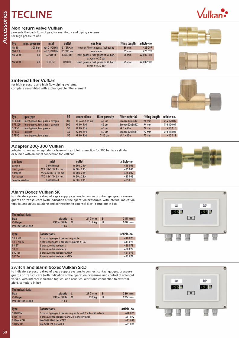
50
A
cces
sori
es TECLINE
Alarm Boxes Vulkan SKto indicate a pressure drop of a gas supply system, to connect contact gauges/pressure guards or transducers (with indication of the operation pressures, with internal indication (optical and acustical alert) and connection to external alert, complete in box
Switch and alarm boxes Vulkan SKDto indicate a pressure drop of a gas supply system, to connect contact gauges/pressure guards or transducers (with indication of the operation pressures and control of solenoid valves, with internal indication (optical and acustical alert) and connection to external alert, complete in box
Technical data Box plastic L 210 mm B 215 mmVoltage 230V/50Hz M 1,1 kg H 100 mmProtection class IP 44
Technical data Box plastic L 290 mm B 280 mmVoltage 230V/50Hz M 2,8 kg H 175 mmProtection class IP 65
Type Connections article-no.SK 2 KD 2 contact gauges / pressure guards 410 075SK 2 KD ex 2 contact gauges / pressure guards ATEX 411 075SK 2T 2 pressure transducers 420 078SK 3T 3 pressure transducers 420 079SK2Tex 2 pressure transducers ATEX 421 078SK3Tex 3 pressure transducers ATEX 421 079
Type Connections article-no.SKD KDM 2 contact gauges / pressure guards and 2 solenoid valves 420 075SKD TM 2 pressure transducers and 2 solenoid valves 411 092SKDex KDM like SKD KDM, but ATEX 411 090SKDex TM like SKD TM, but ATEX 421 081
Typ gas type PS connections filter porosity filter material fitting length article-no.SFT300 inert gases, fuel gases, oxygen 300 M 24x1,5 RHak 45 µm Bronze (CuSn12) 94 mm 414 120 07SFT200 inert gases, fuel gases, oxygen 200 G 3/4 RHi 45 µm Bronze (CuSn12) 94 mm 410 120 07SFT50 inert gases, fuel gases 50 G 3/4 RHi 40 µm VA 1.4404 72 mm 410 118SFT40 oxygen 40 G 3/4 RHi 50 µm Bronze (CuSn11) 72 mm 410 118 01SFT50 inert gases, fuel gases 50 G 3/4 RHi 7-10 µm VA 1.4404 72 mm 410 119
Non return valve Vulkanprevents the back flow of gas, for manifolds and piping systems,for high pressure use
Sintered filter Vulkanfor high pressure and high flow piping systems,complete assembled with exchangeable filter element
Adapter 200/300 Vulkanadapter to connect a regulator or hose with an inlet connection for 300 bar to a cylinderor bundle with an outlet connection for 200 bar
gas type inlet outlet article-no.oxygen G3/4RH nut W 30 x 2 RH 425 005inert gases W 21,8x1/14 RH nut W 30 x 2 RH 425 006nitrogen W 24,32x1/14 RH nut W 30 x 2 RH 425 002fuel gases W 21,8x1/14 LH nut W 30 x 2 LH 425 008compressed air G5/8RH nut W 30 x 2 RH 425 010
Typ max. pressure inlet outlet gas type fitting length article-no.NV 30 300 bar nut G1/2RHk G1/2RHak oxygen / inert gases / fuel gases 89 mm 423 097NVA 20 25 nut G1/2RHk G1/2RHak acetylene 89 mm 423 093NV 40 HF 40 G3/4RHif G3/4RHif inert gases / fuel gases to 40 bar / 95 mm 420 097 05 oxygen to 20 bar NV 40 HF 40 G1RHif G1RHif inert gases / fuel gases to 40 bar / 95 mm 420 097 06 oxygen to 20 bar

51
A
cces
sori
esTECLINEPressure transducer Vulkanto determine the operating pressure and to alert a pressure drop, connection pressure: G 1/4RHaf, Supply voltage: 10 – 30 VDC, Outlet signa: 4 – 20 mA, Cable length 2m
T-piece Vulkanfor high pressure, to connect a pressure guard, transducer or contact gauge to a manifold or in a pipeline
connection connections article-no.G 3/4 RH G 1/4RH acc. to EN 837 410 070M24x1,5 RH G 1/4RH acc. to EN 837 414 070
Type Pressure range Gas Type article-no.DT 300 0 - 300 bar oxygen/inert gases 420 085 11DT 20 0 - 20 bar oxygen/inert gases 420 085 13DT 300 ex 0 - 300 bar fuel gases 420 086 11DT 20 ex 0 - 26 bar acetylene 420 084 01
Safety gauge Vulkan acc. to ISO 5171with steel body Ø 63 mm
Contact gauge Vulkan acc. to DIN EN 837-1stainless steel body Ø 63 mm with Reed contact,also for ATEX area
Technical data Body steel coated diameter Ø 63 mmConnection brass thread G 1/4 RHTemperature -20 to +60 °C acc. to ISO 5171, class 2.5
Technical data Body stainless steel diameter Ø 63 mmAnschluss stainless steel connection G 1/4 RHContakt Reed type opens with falling pressurepower 10W at DC and 10VA at AC switch hysteresis 1,6% maxmax. switch voltage 24 V max. switch power 0,4 Atemperature -30 to +75 °C acc. to DIN EN 837-1, class 1.6
gas type working pressure scale article-no.acetylene 0 - 26 bar 0 - 40 / 26 bar 401 002 0 – 1,5 bar 0 - 2,5 / 1,5 bar 401 022oxygen 0 - 300 bar 0 - 400 / 300 bar 401 018and 0 – 200 bar 0 - 315 / 200 bar 401 001other gases 0 – 100 bar 0 - 160 / 100 bar 401 040 0 – 60 bar 0 - 100 / 60 bar 401 097 0 – 40 bar 0 - 60 / 40 bar 401 008 0 – 20 bar 0 - 40 / 20 bar 401 026 0 – 10 bar 0 - 16 / 10 bar 401 021 0 – 6 bar 0 - 10 / 6 bar 401 030 0 – 4 bar 0 - 6 / 4 bar 401 029 0 – 2,5 bar 0 - 4 / 2,5 bar 401 036 0 – 1,5 bar 0 - 2,5 / 1,5 bar 401 017 0 – 1 bar 0 - 1,6 / 1 bar 401 035CO2 /argon 0 - 20 Nl/min. 0 - 20 Nl/min. 401 024 0 - 30 Nl/min. 0 - 30 Nl/min. 401 028
gas type working pressure scale article-no.acetylene 0 - 26 bar 0 - 40 / 26 bar 401 103 0 - 1,5 bar 0 - 2,5 / 1,5 bar 401 107oxygen 0 - 300 bar 0 - 400 / 300 bar 401 102and 0 - 200 bar 0 - 250 / 200 bar 401 101other gases 0 - 100 bar 0 - 160 / 100 bar 401 112 0 - 40 bar 0 - 60 / 40 bar 401 108 0 - 20 bar 0 - 40 / 20 bar 401 106 0 - 10 bar 0 - 16 / 10 bar 401 110
Thickness packing unit article-no.1,5 mm 20 pieces 300 017 220,8 mm 40 pieces 300 018 40
Gauge seals from aluminium 11 x 5,5 mm x 5,5 mm

52
A
cces
sori
es TECLINE
Balloon valve VulkanKink valve to fill up Gas balloons, for 200 bar connection W 21,8 x 1/14RH with hand tight nut
Gas saver Vulkansaves fuel gas and oxygen complete with pilot flame, connection oxygen G 1/4 RH, connection fuel gases G 3/8 LH
Test gauge Vulkanto check the cylinder pressure, with high pressure gauge and purge valve,connections acc. to DIN 477
Typ article-no.with thread 95 880with needle tip 95 885
gas type article-no.acetylene/oxygen 403 101propane or natural gas/oxygen 403 103
gas type pressure connection article-no.oxygen 200 bar G 3/4 RH 420 958inert gases ” W 21,8x1/14 RH 420 956nitrogen W 24,32x1/14 RH 420 953fuel gases ” W 21,8x1/14 LH 420 954compressed air ” G 5/8 RH 420 957testing gas ” M 19 x 1,5 RH 420 952acetylene 26 bar clamp 420 959oxygen 300 bar W 30 x 2 RH 423 958inert gases ” W 30 x 2 RH 423 956fuel gases ” W 30 x 2 LH 423 954compressed air ” W 30 x 2 RH 423 957
Hand tight connections 200 barfor hoses and regulators, to connect to cylinder valves, connections acc. to DIN 477
gas type connection DIN 477-1 article-no.oxygen G 3/4 RH no. 9 410 845nitrogen W 24,32 x 1/14 RH no. 10 410 345inert gases W 21,8 x 1/14 RH no. 6 410 645fuel gases W 21,8 x 1/14 LH no. 1 410 445nitrous oxide G 3/8 RH no. 11 410 844testing gas M 19x1,5 LH no. 14 410 245
Rubber protection cap acc. to DIN 32503colour grey, acc. to DIN 32 503, for safety gauges Ø 63 mm, not for contact gauges
Connection seals for regulators 200 and 300 bar
gas type pressure material packing unit article-no.oxygen/ 200 bar fibermaterial 50 pieces 300 001 50inert gases and ” polyamide 30 pieces 300 005 30fuel gases ” copper 2 pieces 410 395 12 ” PTFE 10 pieces 300 019 10acetylene 26 bar rubber 10 pieces 300 011 10testing gas 200 bar fibermaterial 10 pieces 300 004 10nitrous oxide 80 bar fibermaterial 10 pieces 300 012 10oxygen/ 300 bar Viton 10 pieces 911 025 10inert gases and 300 bar Viton 10 pieces 911 028 10fuel gases EPDM 10pieces 911 025 12
article-no. 401 057

53
A
cces
sori
esTECLINE
Shut off valve Vareo DVfor high pressure PN 300 for all gases, except acetylene
inlet outlet article-no.M 24 x 1,5 RH nut M 24 x 1,5 RH male 424 004M 24 x 1,5 RH male M 24 x 1,5 RH nut 424 114G 3/4 RH nut G 3/4 RH male 424 113G 3/4 RH male G 3/4 RH nut 424 108
Purge valvefor High pressure complete with clamp ring for relief pipe 10 mm
Connection article-no.M 24 x 1,5 RHk nut 414 039 05G 3/4 RHf nut 413 037
Gas type labelsin gas type colour
gas type 36 x 26 mm 180 x 38 mmoxygen 420 512 420 502acetylene 420 513 420 503CO2 420 514 420 504inert gases 420 515 420 505argon 420 517 420 506nitrogen 420 511 420 501hydrogen 420 518 420 507helium 420 519 420 508nitrous oxide 420 522 420 509propane 420 520 420 510compressed air 420 516 420 530mixed gas 420 521 420 533fuel gases 420 523 420 532forming gas 420 524 420 531

54
Acc
esso
ries
- T
ub
e fi
ttin
gs
and
fla
shb
ack
arre
sto
rs TECLINE
Flashback arrestors VU/RTC acc. to ISO 5175/EN 730to connect to regulator, consisting of filter, non return valve, sintered element and thermal cut off valve and flame dispenser
Flashback arrestors VU/RT91C HiFlow acc. to ISO 5175/EN 730to connect to regulator, consisting of filter, non return valve, sintered element and thermal cut off valve and flame dispenser
type gas type connection thread article-no.VU/RTC-F 3/8 fuel gases G 3/8 LH 430 221VU/RTC-O 1/4 oxygen G 1/4 RH 430 225
type gas type connection thread article-no.VU/RT91C-F 3/8 fuel gases G 3/8 LH 430 321VU/RT91C-F 1/2 ” G 1/2 LH 430 324VU/RT91C-O 1/4 oxygen G 1/4 RH 430 325VU/RT91C-O 1/2 ” G 1/2 RH 430 329
Technical data Body brass acetylene 1,5 bar Q max 6,0 Nm³/hSeals EPDM oxygen 20 bar Q max 80,0 Nm³/hFilter sintered bronze propane 3,5 bar Q max 12,5 Nm³/hLeakage rate 1x10⁻⁶mbar l/s L 83 mm M 155 gTemperature -20 to +60 °C d Ø 22 mm acc. to ISO 5175/EN 730
Technical data Body brass acetylene 1,5 bar Q max 23 Nm³/hSeals EPDM oxygen 20 bar Q max 300 Nm³/hFilter sintered bronze propane 3,5 bar Q max 50 Nm³/hLeakage rate 1x10⁻⁶mbar l/s L 110 mm M 425 gTemperature -20 to +60 °C d Ø 34 mm acc. to ISO 5175/EN 730
Tube fittings with clamp ring brass and stainless steelto connect to regulator Vulkan or for pipelines
connection Ø pipe male stainless steel brassG 1/4 RH 6 mm up to PN 300 420 855 up to PN 270 420 755 8 mm 420 856 420 756 10 mm 420 857 420 757 12 mm 420 858 420 758G 3/8 RH 6 mm up to PN 300 420 860 up to PN 270 420 760 8 mm 420 861 420 761 10 mm 420 862 420 762 12 mm 420 863 420 763G 1/2 RH 8 mm up to PN 300 420 866 up to PN 260 420 766 10 mm 420 867 420 767 12 mm 420 868 420 768 15 mm 420 869 420 769 18 mm 420 870 420 770 20 mm 420 871 G 3/4 RH 12 mm up to PN 300 420 875 up to PN 250 420 775 18 mm 420 876 420 776 20 mm 420 877 420 778 22 mm 420 878 25 mm 420 879

55
A
cces
sori
es f
or
reg
ula
tors
an
d s
par
e p
art
sets
Vu
lkanTECLINE
Accessories for regulatorfor all regulators Vulkan, for pressure regulators, manifold regulators, In-line regulators and tapping point regulators
Chrome-plating of regulatorsregulator complete chrome-plated and specially cleaned
Metal diaphragm for regulatormetal diaphragm from stainless steel for higher gas quality up to 5.0
Special working pressure ranges for regulatorsother working pressure ranges for standard regulators for the following types: F 10/20, F 10 F, L 10/20, E 10/20, H 10/20
Surcharge for special inlet- & outlet connectionsfor regulators
Typ article-no.F10/20/40/60 F10F L10/20/40 E10/20/40 H10/20/40/60 912 930F10/2 / F15/2 912 932HR20/40/60 LR20/40/60 ER20/40 912 934
Typ article-no.F10/20/40/60 F10F L10/20/40 E10/20/40 H10/20/40/60 912 935F10/2 / F15/2 912 938HR20/40/60 LR20/40/60 ER20/40 912 936
range article-no.0 - 1,5 / 2,5 bar 912 9600 - 2,5 / 4 bar 912 9610 - 4 / 6 bar 912 9620 - 6 / 10 bar 912 963
type article-no.Special inlet connection 912 950Special outlet connection 912 952
every single regulator can be fitted with special in- and outlet connections likeclamp ring connections or brazing or welding connecting pieces, an adaptation isnecessary, which is described by the following numbers
Spare part sets for regulatorsthe spare part sets are mostly divided into high pressure sets and low pressuresets and contain all necessary parts, filters and seals for a proper refurbishment
Spare part sets for Pressure regulators
regulator type gas type high pressure low pressure low pressure Standard MetallmembranF10/200 Standard oxygen/inert gases/fuel gases 900208 909208 919218F10 acetylene acetylene 900209 909209 -F10/ F10F 200bar oxygen/inert gases/fuel gases 900218 909208 919218F10/ F10F 200bar helium/hydrogen 90021801 909208 919218F10/ F10F 300bar oxygen/inert gases/fuel gases 900318 909208 919218F10/ F10F 300bar helium/hydrogen 90031801 909208 919218F15/200 oxygen/inert gases/fuel gases 900218 909217 919217F15/300 oxygen/inert gases/fuel gases 900318 909217 919217F20/200bar oxygen/inert gases/fuel gases 900218 909219 919219F20/300bar oxygen/inert gases/fuel gases 900318 909219 919219F40/200 oxygen/inert gases/fuel gases 900217 909235 919208F40/300 oxygen/inert gases/fuel gases 900317 909235 919208F10/2 200 oxygen/inert gases/fuel gases 900228 909228 919228F10/2 300 oxygen/inert gases/fuel gases 900328 909228 919228F15/2 200 oxygen/inert gases/fuel gases 900227 909227 919228F15/2 300 oxygen/inert gases/fuel gases 900327 909227 919228

56
Spar
e p
art
sets
Vu
lkan TECLINE
Spare part sets for manifold regulators
regulator type gas type high pressure low pressure low pressure standard metal diaphragmH10/200 oxygen/inert gases/fuel gases 900 218 909 207 919 218H10/200 helium/hydrogen 900 218 01 909 207 919 218H10/300 oxygen/inert gases/fuel gases 900 318 909 207 919 218H10/300 helium/hydrogen 900 318 01 909 207 919 218H20/200 oxygen/inert gases/fuel gases 900 218 909 218 919 219H20/300 oxygen/inert gases/fuel gases 900 318 909 218 919 219H40/200 oxygen/inert gases/fuel gases 900 217 909 238 919 208H40/300 oxygen/inert gases/fuel gases 900 317 909 238 919 208HR20/200 oxygen/inert gases/fuel gases 900 225 909225 919 245HR20/300 oxygen/inert gases/fuel gases 900 325 909 225 919 245HR40/60 /200 inert gases/fuel gases 900 225 909 245 919 245HR40/60 /200 oxygen 900 225 - 919 245HR40/60 /300 inert gases/fuel gases 900 325 909 245 919 245HR40/60 /300 oxygen 900 325 - 919 245HA5 acetylene 900 209 909 209 919 209HA10 acetylene 900 209 909 209 919 209H20 acetylene acetylene 900 239 909 239 919 209
Spare part sets for In-line regulator
regulator type gas type high pressure low pressure low pressure standard metal diaphragmL10 oxygen/inert gases/fuel gases 900 218 909 208 919 218L10 helium/hydrogen 900 218 01 909 208 919 218L20 oxygen/inert gases/fuel gases 900 208 909 218 919 219L20 helium/hydrogen 900 218 01 909 218 919 219L15 oxygen/inert gases/fuel gases 900 208 909 217 919 217L40 oxygen/inert gases/fuel gases 900 217 909 238 919 208L10/2 oxygen/inert gases/fuel gases 900 228 909 228 919 228L15/2 oxygen/inert gases/fuel gases 900 227 909 227 919 228LD 1 oxygen/inert gases, not for CO2 900 535 -LD 1 carbon dioxide CO2 900 535 01 -LH16 oxygen/inert gases/fuel gases 900 122 -LH25 oxygen/inert gases/fuel gases 900 121 -LR20 oxygen/inert gases/fuel gases 900 225 909 225 919 245LR40/60 oxygen 900 225 - 919 245LR40/60 inert gases/fuel gases 900 225 909 245 919 245L10 acetylene acetylene 900 209 909 209 919 209
Spare part sets for flowmeter complete for regulator with flowmeter
for type gas type article-no.flowmeter complete F10F/ E10F CO2 /argon 1 - 14 Nl/min. 909 405flowmeter complete F10F/ E10F CO2 /argon 4 - 32 Nl/min. 909 455flowmeter complete F10F/ E10F hydrogen 2,6 - 26 Nl/min. 909 606flowmeter complete F10F/ E10F forming gas 2 - 23 Nl/min. 909 605flowmeter complete F10F/ E10F nitrogen 4 -42 Nl/min. 909 615
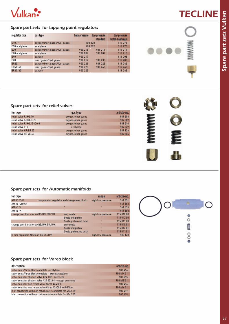
57
Spar
e p
art
sets
Vu
lkanTECLINE
Spare part sets for tapping point regulators
for type gas type article-no.relief valve F/H/L 10 oxygen/other gases 909 508relief valve F/H/L/E 20 oxygen/other gases 909 509relief valve F/H/L/E 40/60 oxygen/other gases 909 510relief valve F10 acetylene 909 229relief valve HR/LR 20 oxygen/other gases 909 226relief valve HR 40/60 oxygen/other gases 909 266
Spare part sets for relief valves
regulator type gas type high pressure low pressure low pressure standard metal diaphragmE10 /F oxygen/inert gases/fuel gases 900 278 919 278E10 acetylene acetylene 900 279 919 278E20 oxygen/inert gases/fuel gases 900 218 909 219 919 219E20 acetylene acetylene 900 209 909 209 919 218E40 oxygen 900 217 - 919 208E40 inert gases/fuel gases 900 217 909 235 919 208ER20 oxygen/inert gases/fuel gases 900 225 909 225 919 245ER40/60 inert gases/fuel gases 900 225 909 245 919 245ER40/60 oxygen 900 225 - 919 245
Spare part sets for Automatic manifolds
Spare part sets for Vareo block
for type range article-no.AM 35 /D/K complete for regulator and change over block high/low pressure 941 851AM 35 /DH/KH ” ” 941 853AM 45 /K ” ” 941 855AM 55 /K ” ” 941 858change over block for AM35/D/K/DH/KH only seals high/low pressure 115 040 00 Seals and piston ” 115 042 00 Seals, piston and bush ” 115 041 00change over block for AM45/D/K 55 /D/K only seals ” 115 040 01 Seals and piston ” 115 042 01 Seals, piston and bush ” 115 041 01In-line regulator AD 35 off AM 35 /D/K high/low pressure 900 128
description article-no.set of seals Vareo block complete - acetylene 900 414set of seals Vareo block complete – except acetylene 900 414 01set of seals for shut off valve 424 002 – acetylene 900 515set of seals for shut off valve 424 002 01 – except acetylene 900 415 01set of seals for non return valve Vareo 424003 900 416set of seals for non return valve Vareo 424003, with Filter 900 416 01inlet connection with non return valve complete for 414 515 900 417inlet connection with non return valve complete for 414 525 900 418

58
Acc
esso
ries
fo
r re
gu
lato
rs TECLINESurcharge for special connections for pressure regulatorsevery pressure regulator can be fitted with the following cylinder connections,which are mostly on stock
gas type country/countries VDMA standard, no./type connection article-no.oxygen Australia also for Argon and nitrogen 1.1 AS2473, Typ 10 AG G5/8RHk 912101 Belgium 1.2 NBN 226 AG G5/8RHk 912102 Danmark, Norway, Croatia, Czech republic, Slowakia, Slovenia 1.3 DS727.2 nut W21,8x1/14RHf 912103 Germany, Austria, Poland, Switzerland, Czech republic 1.4 DIN 477-1, Nr. 9 nut G3/4RHf 912104 France, Spain Portugal Greece, Northern Africa 1.5 NFE 29656 AG W22,91x1/14RHk 912105 Great Britain, Egypt, Asia, South Africa, Arabia also for Argon and nitrogen 1.6 BS342-1, Nr. 3 AG G5/8RHk 912106 Italy, Cyprus 1.7 UNI 4406 nut W21,7x1/14 RHf 912107 Netherlands 1.8 NEN3268 RI2 AG G5/8RHk 912108 Sweden, Norway, Finland, Greece, Turkey 1.9 SMS 690 nut W21,8x1/14RHf 912109 Switzerland 1.11 SN 219 505 Bl. 2 nut G3/4RHf 912111 USA, South America 1.10 CGA 540 nut 0,908x1/14 RHk 912110acetylen Australia also for hydrogen 2.1 AS2473, Typ 20 AG G5/8LHk 912207 Belgium 2.2 NBN 226, Typ D clamp 912202 Danmark, Sweden, Norway, Finland, South America, 2.3 DS727.7 AG G3/4RHf 912203 Germany, Greece, Austria, Poland, Czech republic, Switzerland, Slowakia,Turkey, Cyprus 2.4 DIN 477-1, Nr. 3 clamp 912204 France, Spain Portugal, Northern Africa 2.5 NFA 84421, Typ 2 clamp 912205 France, Spain Portugal, Northern Africa 2.6 NFE 29658 AG G5/8LHk 912206 Great Britain, Egypt, Asia, South Africa, Arabia 2.7 BS342-1, Nr. 2 AG G5/8A-LHk 912207 Italy 2.8 UNI 4411 clamp 912208 Netherlands 2.11 NEN3268 Typ 4 clamp 912211 USA, Asia 2.14 CGA 510 AG 0,880x1/14LHk 912214 Switzerland 2.15 SN 219 505 Bl. 6 AG G3/4RHf 912215CO2 Danmark, Norway, Croatia, Czech republic, Slowakia, Slovenia 1.3 DS727.2 nut W21,8x1/14RHf 912103 Czech republic, Slowakia 1.4 DIN 477-1, Nr. 9 nut G3/4RHf 912104 Italy 1.7 UNI 4406 nut W21,7x1/14 RHf 912107 Sweden 1.9 SMS 690 nut W21,8x1/14RHf 912109 Australia 4.1 AS2473, Typ 30 nut 0,860x1/14RHf 912401 Germany, Belgium, Finland, Austria, Poland, Switzerland 4.2 DIN 477-1, Nr. 6 nut W21,8x1/14 RHf 912402 France, Spain, Portugal, Greece, Northern Africa also for Argon and nitrogen 4.3 NFE29650 Typ C nut W21,7x1/14RHk/f 912403 Great Britain, Egypt, Asia, South Africa, Arabia 4.4 BS342-1, Nr. 8 nut 0,860x1/14RHf 912404 Belgium, Netherlands 4.5 NEN RU1 nut W21,8x1/14 RHf 912405 USA, South America 4.6 CGA 320 nut 0,830x1/14RHf 912406 Switzerland 4.7 SN 219 505 Bl. 7 nut W21,8x1/14 RHf 912407argon Slowakia 1.4 DIN 477-1, Nr. 9 nut G3/4RHf 912104 Germany, Austria, Poland, Sweden, Switzerland, Czech republic 4.2 DIN 477-1, Nr. 6 nut W21,8x1/14 RHf 912402 Danmark, Norway 5.1 DS727.3 nut W24,32x1/14RHf 912501 Italy 5.2 UNI 4412 AG W24,5x1/14RHk 912502 Netherlands, Sweden 5.3 NEN RU3 nut W24,32x1/14RHf 912503 USA, South America 5.5 CGA 580 AG 0,960 x 1/14 RHk 912505 Finland 7.1 DIN 477-1, Nr. 10 nut W24,32x1/14RHf 912701hydrogen Germany, Finland, Norway, Austria, Poland, Sweden, Switzerland, Slowakia Czech republic 3.1 DIN 477-1, Nr. 1 nut W21,8x1/14LHf 912301 France, Spain, Portugal, Greece, Northern Africa 3.2 NFE29650 Typ E nut W21,7x1/14LHk 912302 Great Britain, Egypt, Asia, South Africa, Arabia 3.3 BS342-1, Nr. 4 AG G5/8A-LHk 912303 Italy 3.5 UNI 4405 nut W20x1/14LHf 912305 Netherlands 3.6 NEN LU1 nut W21,8x1/14LHf 912306 Danmark 6.1 DS727.1 nut W21,8x1/14LHf 912601 USA, South America 6.4 CGA 350 nut 0,830x1/14RHk 912604nitrogen Danmark, Norway 5.1 DS727.3 nut W24,32x1/14RHf 912501 Netherlands 5.3 NEN RU3 nut W24,32x1/14RHf 912503 Sweden 5.4 SS2238, Typ A nut W24,32x1/14RHf 912504 USA, South America 5.5 CGA 580 AG 0,960 x 1/14 RHk 912505 Germany, Finland, Austria, Poland, Switzerland, Slowakia, Czech republic 7.1 DIN 477-1, Nr. 10 nut W24,32x1/14RHf 912701 Italy 7.2 UNI 4409 AG W21,7x1/14RHf 912702

59
Flo
w c
har
ts -
max
. flo
wFLOW CHARTStable 1
Automatic manifold AM 35/K Base stations Modula Vareo
Conversion factorsAll flow data are measured with compressed air (acc. to DIN), except acetylene (measured with acetylene).Please see following conversion factors for the flow of other gases:
at inlet pressure = 2 x working pressure + 1 bar
table 2 Manifold regulators
Tapping point regulator acetylene
table 3 Pressure regulators, also 300 bar
Tapping point regulators
table 4 Pressure regulators, also 300 bar
Tapping point regulator
gas type Chemical sign Conversion factors gas type Chemical sign Conversion factorsargon Ar 0,85 propane C
3H
8 0,80
helium He 2,70 oxygen O2 0,95
carbon dioxide CO2 0,84 nitrogen N
2 1,00
nitrous oxide N2O 0,80 hydrogen H
2 3,80
For more information – please do not hesitate to contact us!
working pressure in barworking pressure in bar
flow
in N
m3 /
h
flow
in N
m3 /
h
working pressure in barworking pressure in bar
flow
in N
m3 /
h
flow
in N
m3 /
h

60
Flo
w c
har
ts -
max
. flo
w FLOW CHARTStable 5
Manifold regulator also 300 bar
table 6 In-line regulator
acetylene and propane
table 7 In-line regulator
table 8 In-line fin regulator
Conversion factorsAll flow data are measured with compressed air (acc. to DIN), except acetylene (measured with acetylene).Please see following conversion factors for the flow of other gases:
gas type Chemical sign Conversion factors gas type Chemical sign Conversion factorsargon Ar 0,85 propane C
3H
8 0,80
helium He 2,70 oxygen O2 0,95
carbon dioxide CO2 0,84 nitrogen N
2 1,00
nitrous oxide N2O 0,80 hydrogen H
2 3,80
For more information – please do not hesitate to contact us!
at inlet pressure = 2 x working pressure + 1 bar
working pressure in barworking pressure in bar
flow
in N
m3 /
h
flow
in N
m3 /
h
working pressure in barworking pressure in bar
flow
in N
m3 /
h
flow
in N
m3 /
h

61
LABLINE
VULKAN LABLINE FOR HIGH PURITY GASES UP TO 5.0
Vu
lkan
Lab
Lin
e
61

Lab
Lin
e V
ulk
an
62
LABLINEA
uto
mat
ic m
anif
old
s M
od
ula
Automatic manifold Modula AM 35/300 Kfor oxygen and other gases except acetylene Modula add on system, can be expanded to your requirementsconsisting of2 Manifold regulators H20 acc. to ISO 7291, adiabatic compression tested,2 ND-purge valves, 1 In-line regulator AD 35,1 Automatic change over block, 1 Main shut off valve,2 contact gauges with Reed switch (optional) acc. to DIN EN 837-1
complete on stainless steel base plate
Automatic manifold ModulaAt the fully automatic change-over device, the working pressure is adjusted through the pressure regulator. The switch from the empty to the full side will occur here auto- matically with the help of the change-over block which is installed between the two main pressure regulators. It is important that both manifold regulators are adjusted to the same working pressure. This is done by the manufacturer. If the cylinders or bundles on one side are empty, the pressure of the cylinders is reduced, leading to a reduction of the working pressure of the manifold regulator adjacent to the change-over block. If the working pressure of the main pressure regulator drops by more than 3-4/5-7 bar below the programmed pressure, the tension of the spring inside of the change-over block will cause the piston to move to the full side. If the empty cylinders or bundles are replaced, they must be opened again, so that the full pressure comes up to the automatic change- over device. This does not cause another switch of the change-over block. The switch will occur only at the time when the side currently in use is empty.
All products of the Vulkan LabLine range are manufactured from brass and chrome-plated after a special Vibratory Finishing cleaning processes, according to the latest environmental requirements. This is a process that works on a mechanical basis for surface finishing. In the working bowl of the machines the grinding media (Chips) and work pieces are being brought to a relative movement to each other. Water and compound control the required surface treatment and guarantee the latest “state-of-the-art” in surface treatment. All Vulkan LabLine components undercut the limit of maximal 100 mg/m² of fat content of the surfaces.
The leak rate is approx. 10-6 therefore all parts are helium leak proof. The Vulkan LabLine products are designed and manufactured according to the latest DIN, EN and ISO – standards and fulfil also the requirements of the PED, and the German DGUV – rules.
The high pressure compensation Effect on all high pressure regulators allows an absolute constant working pressure. Thus it succeeds nearly in process performance of a double stage regulator for the price of a single stage regulator. It secures therefore a reproductive and absolute constant working result.
The Vulkan LabLine programme can offer you an extensive range of accessories, as for example Vareo block rail systems, high pressure metal hoses, purge valves or additional filters. Many national and inter-national cylinder connections are available, as well as different pressure ranges or flow ranges for flowmeter regulators and outlet connections.
If you need more information or technical details, please do not hesitate to contact us.
Technical data Flow chart see enclosureBody brass chrome-plated pe max 300 bar pa 0 - 10 barSeals EPDM, polyamide, Viton, PTFE Qmax 50 Nm³/h at pa 10 barDiaphragm stainless steel de M 24x1,5 RH da clamp ring 8 mmLeakage rate 1x10⁻⁶mbar l/s B 450 mm H 420 mmTemperature -20 to +60 °C T 210 mm M 11 kg
62
oxygen 474 851 473 850nitrogen 474 351 473 350argon 474 651 473 650CO2 474 651 06 473 650 06helium 474 651 26 473 650 26hydrogen 474 451 473 450compressed air 474 751 473 750
gas type article-no. with contact gauge article-no. without contact gauge

Lab
Lin
e V
ulk
an
63
LABLINE
Man
ual
man
ifo
lds
Mo
du
la V
areo
63
Base station Modula Vareo BS 50consisting of one distributing block Vareo with two inlets for 2x1 cylinder or 2x1 bundle or for connection of further distributing blocks Vareo Vareo 1 Manifold regulator Vulkan H 10, acc. to ISO 7291, adiabatic compression tested, 1 Main shut off valve, complete on stainless steel base plate, purge valve optional.
Manifold stations Modula VareoOne manifold station has two connections for cylinders or bundles. It can be connected to one base station and one other manifold station or with two other manifold stations. The manifold stations consists of two sinter filters, two non return valves and two shut off valves. Optionally every inlet can be equipped with a purge valve, including the possibility to install a purging pipe system.
Purge valve Vareoto fit into manifold station or base station Modula Vareo, complete with shut off valve and optionally with clamp ring outlet Ø 10 mm for connection of a purging pipe system
Manual manifold Modula Vareo 300 barModula add-on system, for cylinders- and bundles, flexible and always expandable. The heart of this system is the distributing block Modula Vareo which consists of 2 inlets for 2 cylinders or bundles and 2 outlets to connecting a manifold regulator or further distributing blocks Modula Vareo.
The distributing block Modula Vareo contains the following components:2 shut off valves to shut off the cylinders or bundles,2 non return valves prevent the reverse flow of the gas into empty cylinders or bundles,2 sinter metal filters prevent the penetration of dirt and extendthe life cycle of the complete manifold.Optionally: 2 purge valvesYour advantages of Modula Vareo:- compact construction - all functions in one block- modular system - always expandable- easy assembly - only few thread connections- easy maintenance - all components are easily exchangeable- individual - for 300 bar or 200 barThese components are available:
Base station BSOne distributing block Modula Vareo with manifold regulator and shut off valvecompletely fixed. For 2 x 1 cylinders or 2 x 1 bundles or for the connection of furthermanifold stations VS to connect more cylinders or bundles.
Manifold station VSReplaces the traditional rail system. To connect to other manifold systems or to connect to a base station.
Technical data Flow chart see enclosureBody brass chrome-plated pe max 300 bar pa 0 - 10 barSeals EPDM, polyamide, Viton Qmax 50 Nm³/h at pa 10 barDiaphragm stainless steel de M 24x1,5 RH da clamp ring 8 mmLeakage rate 1x10⁻⁶mbar l/s B 570 mm H 250 mmTemperature -20 to +60 °C T 210 mm M 10 kg
Technical data Body brass chrome-plated pmax 300 bar Seals EPDM de M24x1,5RH RH da M24x1,5RH mmLeakage rate 1x10⁻⁶mbar l/s B 190 mm H 190 mmTemperature -20 to +60 °C T 235 mm M 5 kg
gas type article-no.oxygen 474 810nitrogen 474 310argon 474 610CO2 474 610 06helium 474 610 26hydrogen 474 410compressed air 474 710
type article-no.for oxygen, inert gases, fuel gases except acetylene 474 515for acetylene inlet W21,8x1/14LH 474 525
type article-no.without clamp ring in outlet 474 038with clamp ring in outlet 474 037to connect to outlet of Vareo VS 474 039

64
Rai
l sys
tem
s V
areo
/Sin
gle
cyl
ind
er m
anif
old
s V
areo LABLINE
Connecting pipes Vareo DN 10to connect a manifold station to a base station or to automatic manifolds Modula as well as manifold stations to each other
connecting pipe VB, 90° bent, length 2x 150 mm, to connect a manifold station to a base station
connecting pipe VU, 2x bent, length 300 mm, to connect a manifold station to an automatic manifold and Base station for cylinders
connecting pipe VF, straight, length 400 mm, to connect two manifold stations, for cylinders
Single cylinder manifold Modula SE 10/300/Kfor oxygen and other gases , Modula add-on system, also for laser gases consisting of:1 HP-shut off valve,1 manifold regulator H 10, acc. to ISO 7291, adiabatic compression tested,1 main shut off valve,1 purge valve, 1 cylinder rack,
complete on stainless steel base platefor acetylene not chrome-plated, including flashback arrestor acc. to EN 730, adjustable 0-1,5 bar, 5 Nm3/h, outlet G 3/8 LHak acc. to EN 560
Single cylinder manifold Modula SE 10/2 300/Kfor oxygen and other gases , Modula add-on system, also for laser gases consisting of: 1 HP-shut off valve,1 manifold regulator H10/2 double stage, acc. to ISO 7291, adiabatic compression tested, 1 main shut off valve,1 purge valve,1 cylinder rack complete on stainless steel base plate
type article-no.for oxygen, inert gases, fuel gases except acetylene 474 560for acetylene 474 590
type article-no.for oxygen, inert gases, fuel gases except acetylene 474 562for acetylene 474 592
type article-no.for oxygen, inert gases, fuel gases except acetylene 474 564for acetylene 474 594
Technical data Flow chart see enclosureBody brass chrome-plated pe max 300 bar pa 0 - 10 barSeals EPDM, polyamide Qmax 50 Nm³/h at pa 10 barDiaphragm stainless steel de M 24x1,5 RH da clamp ring 8 mmLeakage rate 1x10⁻⁶mbar l/s B 420 mm H 280 mmTemperature -20 to +60 °C T 110 mm M 4,5 kg
Technical data Flow chart see enclosureBody brass chrome-plated pe max 300 bar pa 0 - 10 barSeals EPDM, polyamide Qmax 30 Nm³/h at pa 10 barDiaphragm stainless steel de M 24x1,5 RH da clamp ring 8 mmLeakage rate 1x10⁻⁶mbar l/s B 480 mm H 280 mmTemperature -20 to +60 °C T 110 mm M 5,0 kg
gas type article-no. without contact gauge article-no. with contact gaugeoxygen 473 801 474 802acetylene 410 901 410 902nitrogen 473 301 474 302argon 473 601 474 602CO2 473 601 06 474 602 06helium 473 601 26 474 602 26hydrogen 473 401 474 402compressed air 473 701 474 702
gas type article-no. without contact gauge article-no. with contact gaugeoxygen 473 816 474 817nitrogen 473 316 474 317argon 473 616 474 617CO2 473 616 06 474 617 06helium 473 616 26 474 617 26hydrogen 473 416 474 417compressed air 473 716 474 717

65
Cyl
ind
er a
nd
bu
nd
le h
ose
s V
ulk
anLABLINE
Connection Connection article-no. article-no. article-no. article-no. article-no. article-no. to cylinder to Vareo length 800mm length 1.000mm length 1.500mm length 2.000mm length 2.500mm length 3.000mmoxygen G 3/4 RH M24x1,5 RH 425 835 0008 425 835 0010 425 835 0015 425 835 0020 425 835 0025 425 835 0030inert gases W21,8x1/14 RH M24x1,5 RH 425 635 0008 425 635 0010 425 635 0015 425 635 0020 425 635 0025 425 635 0030nitrogen W24,32x1/14 RH M24x1,5 RH 425 335 0008 425 335 0010 425 335 0015 425 335 0020 425 335 0025 425 335 0030fuel gases W21,8x1/14 LH M24x1,5 RH 425 435 0008 425 435 0010 425 435 0015 425 435 0020 425 435 0025 425 435 0030compressed air G 5/8 RH M24x1,5 RH 425 735 0008 425 735 0010 425 735 0015 425 735 0020 425 735 0025 425 735 0030
Connection Connection article-no. article-no. article-no. article-no. article-no. article-no. to cylinder to Vareo length 800mm length 1.000mm length 1.500mm length 2.000mm length 2.500mm length 3.000mmoxygen W30x2 RH M24x1,5 RH 424 835 0008 424 835 0010 424 835 0015 424 835 0020 424 835 0025 424 835 0030inert gases W30x2 RH M24x1,5 RH 424 635 0008 424 635 0010 424 635 0015 424 635 0020 424 635 0025 424 635 0030nitrogen W30x2 RH M24x1,5 RH 424 335 0008 424 335 0010 424 335 0015 424 335 0020 424 335 0025 424 335 0030fuel gases W30x2 LH M24x1,5 RH 424 435 0008 424 435 0010 424 435 0015 424 435 0020 424 435 0025 424 435 0030compressed air W30x2 RH M24x1,5 RH 424 735 0008 424 735 0010 424 735 0015 424 735 0020 424 735 0025 424 735 0030
HP-Stainless steel hose Vareo DN 6stainless steel hose to connect cylinders and bundles to rail systems for manifolds, inside stainless steel tube, outside netting from stainless steel wire with anti kink springs, complete welded and tested
HP-Stainless steel hose Vareo 300 bar
HP-Stainless steel hose Vareo 200 bar
Technical data Seele Ringwellschlauch 1.4571 Geflecht 1fach aus 1.4571komplett verschweißt mit KnickschutzfedernPS max 450 barDN 6 mm
Connection article-no. article-no. article-no. article-no. article-no. article-no. both sides length 800mm length 1.000mm length 1.500mm length 2.000mm length 2.500mm length 3.000mmoxygen G 3/4 RH 415 835 0008 415 835 0010 415 835 0015 415 835 0020 415 835 0025 415 835 0030inert gases W21,8x1/14 RH 415 635 0008 415 635 0010 415 635 0015 415 635 0020 415 635 0025 415 635 0030nitrogen W24,32x1/14 RH 415 335 0008 415 335 0010 415 335 0015 415 335 0020 415 335 0025 415 335 0030fuel gases W21,8x1/14 LH 415 435 0008 415 435 0010 415 435 0015 415 435 0020 415 435 0025 415 435 0030compressed air G 5/8 RH 415 735 0008 415 735 0010 415 735 0015 415 735 0020 415 735 0025 415 735 0030
Connection article-no. article-no. article-no. article-no. article-no. article-no. both sides length 800mm length 1.000mm length 1.500mm length 2.000mm length 2.500mm length 3.000mmoxygen W30x2 RH 414 835 0008 414 835 0010 414 835 0015 414 835 0020 414 835 0025 414 835 0030inert gases W30x2 RH 414 635 0008 414 635 0010 414 635 0015 414 635 0020 414 635 0025 414 635 0030nitrogen W30x2 RH 414 335 0008 414 335 0010 414 335 0015 414 335 0020 414 335 0025 414 335 0030fuel gases W30x2 LH 414 435 0008 414 435 0010 414 435 0015 414 435 0020 414 435 0025 414 435 0030compressed air W30x2 RH 414 735 0008 414 735 0010 414 735 0015 414 735 0020 414 735 0025 414 735 0030
HP-Stainless steel hose standard 300 bar
HP-Stainless steel hose standard 200 bar
HP-Stainless steel hose standard DN 6stainless steel hose to connect cylinders and bundles to rail systems for manifolds, inside stainless steel tube, outside netting from stainless steel wire, with anti kink springs, complete welded and tested

66
Tap
pin
g p
oin
t V
ulk
an LABLINETapping point-regulator Vulkan E 10single stage, with working gauge to adjust the working pressure at the point of use and connection to tapping point
Tapping point Vulkan Alu-Line 3/8complete on aluminium profile, horizontally adjustable, with shut off valve, connection to piping system clamp ring Ø 8 mm, connection for tapping point regulator G3/8RH nut or LH nut, PN 40, acetylene PN 1,5
Technical data Flow chart see enclosureBody brass chrome-plated pe max 20 bar pa 0 - 10 barSeals EPDM Qmax see below at pa see belowDiaphragm stainless steel de G 3/8 RH/LH da see belowLeakage rate 1x10⁻⁶mbar l/s B 120 mm H 180 mmTemperature -20 to +60 °C T 65 mm M 1,0 kg
Technical data Body brass chrome-plated pe max 20 bar pa see belowSeals EPDM Qmax see below at pa see belowDiaphragm stainless steel de G 3/8 RH/LH da see belowLeakage rate 1x10⁻⁶mbar l/s B 120 mm H 220 mmTemperature -20 to +60 °C T 65 mm M 1,0 kg
Tapping point-regulator Vulkan E 10 Fsingle stage with Flowmeter and regulating valve for precise adjustment of the flow per minute
gas type inlet pressure pressure flow inlet outlet article-no.oxygen 20 bar 0 - 10 bar 40 Nm³/h G 3/8 RH nut clamp ring 6mm 178 700acetylene 1,5 bar 0 - 1,5 bar 3,5 Nm³/h G 3/8 LH nut ” 179 700CO2 /argon 20 bar 0 - 10 bar 40 Nm³/h G 3/8 RH nut ” 176 700 ” 0 - 20 Nl/min. 1,2 Nm³/h ” ” 176 720 ” 0 - 30 Nl/min. 1,8 Nm³/h ” ” 176 725helium ” 0 - 10 bar 40 Nm³/h ” ” 176 706nitrogen ” 0 - 10 bar ” G 3/8 RH nut ” 173 700hydrogen ” ” ” G 3/8 LH nut ” 174 700forming gas ” ” ” ” ” 174 835 ” 0 - 20 Nl/min. 1,2 Nm³/h ” ” 174 840 ” 0 - 30 Nl/min. 1,8 Nm³/h ” ” 174 841 ” 0 - 50 Nl/min. 3,0 Nm³/h ” ” 174 842compressed air ” 0 - 10 bar 40 Nm³/h G 3/8 RH nut ” 177 700testing gas ” 0 - 10 bar ” G 3/8 LH nut ” 173 800nitrous oxide ” 0 - 10 bar ” G 3/8 RH nut ” 172 070propane 8 bar 0 - 4 bar 5 kg/h G 3/8 LH nut ” 175 700 8 bar 0 - 2,5 bar 2,5 kg/h ” ” 175 750ethene ” 0 - 1,5 bar 3,5 Nm³/h ” ” 175 760methane ” 0 - 1,5 bar 3,5 Nm³/h ” ” 175 770
gas type flow range pressure inlet outlet article-no.oxygen 1,4 - 14,5 Nl/min. 1,5 bar G 3/8 RH nut Klemmring 6mm 178 715CO2 /argon 1,0 - 6,5 Nl/min. 4,0 bar ” ” 172 725 1,4 - 14,0 Nl/min. 1,5 bar ” ” 172 700 3,0 - 22,0 Nl/min. ” ” ” 172 720 3,6 - 36,0 Nl/min. ” ” ” 172 750 10,0 - 95,0 Nl/min. 9,0 bar ” ” 172 717helium 3,6 - 34,0 Nl/min. 1,5 bar ” ” 174 724 5, 0 - 65,0 Nl/min. ” ” ” 174 725nitrogen 0,3 - 2,0 Nl/min. ” ” ” 173 745 4,0 - 42 Nl/min. ” ” ” 173 750 8,5 - 85,0 Nl/min. 4,0 bar ” ” 173 775hydrogen 1,8 - 18,0 Nl/min. 1,5 bar G 3/8 LH nut ” 174 750 2,6 - 26 Nl/min. ” ” ” 174 755forming gas 2,0 - 23,0 Nl/min. ” ” ” 174 723
for 1 tapping point regulator oxygen acetylene fuel gases inert gases propane compr. air 417 21 001 417 21 0002 417 21 003 417 21 004 417 21 005 417 21 007
for 2 tapping point regulator oxygen acetylene fuel gases inert gases propane compr. airoxygen 417 22 011 417 22 012 417 22 013 417 22 014 417 22 015 417 22 017acetylene 417 22 022 417 22 023 417 22 024 417 220 25 417 22 027fuel gases 417 22 033 417 22 034 417 22 035 417 22 037inert gases 417 22 044 417 22 045 417 22 047propane 417 22 055 417 22 057compressed air 417 22 077

67
In-li
ne
reg
ula
tor
Vu
lkanLABLINE
In-line regulator Vulkan L 10single stage, with safety gauges acc. to ISO 5171
In-line regulator Vulkan L 10/2double stage, with safety gauges acc. to ISO 5171
In-line regulator Vulkan L 15single stage, with safety gauges acc. to ISO 5171
In-line regulator Vulkan L 15/2double stage, with safety gauges acc. to ISO 5171
Technical data Flow chart see enclosureBody brass chrome-plated pe max 20 bar pa 0 - 10 barSeals polyamide, EPDM Qmax 45 Nm³/h at pa 10 barDiaphragm stainless steel de clamp ring 8 mm da clamp ring 8 mmLeakage rate 1x10⁻⁶mbar l/s B 200 mm H 190 mmTemperature -20 to +60 °C T 75 mm M 1,5 kg
Technical data Flow chart see enclosureBody brass chrome-plated pe max 20 bar pa 0 - 10 barSeals polyamide, EPDM Qmax 30 Nm³/h at pa 10 barDiaphragm stainless steel de clamp ring 8 mm da clamp ring 8 mmLeakage rate 1x10⁻⁶mbar l/s B 240 mm H 190 mmTemperature -20 to +60 °C T 75 mm M 2,0 kg
Technical data Flow chart see enclosureBody brass chrome-plated pe max 20 bar pa 0 - 1,5 barSeals polyamide, EPDM Qmax 8 Nm³/h at pa 1,5 barDiaphragm stainless steel de clamp ring 8 mm da clamp ring 8 mmLeakage rate 1x10⁻⁶mbar l/s B 200 mm H 190 mmTemperature -20 to +60 °C T 75 mm M 1,5 kg
Technical data Flow chart see enclosureBody brass chrome-plated pe max 20 bar pa 0 - 1,5 barSeals polyamide, EPDM Qmax 8 Nm³/h at pa 1,5 barDiaphragm stainless steel de clamp ring 8 mm da clamp ring 8 mmLeakage rate 1x10⁻⁶mbar l/s B 240 mm H 190 mmTemperature -20 to +60 °C T 75 mm M 2,0 kg
gas type article-no.oxygen 178 529CO2 /argon 176 529helium 176 529 26nitrogen 173 529hydrogen 174 529compressed air 177 529
gas type article-no.oxygen 178 562CO2 /argon 176 562helium 176 562 26nitrogen 173 562hydrogen 174 562compressed air 177 562
gas type article-no.oxygen 178 551CO2 /argon 176 551helium 176 551 26nitrogen 173 551hydrogen 174 551compressed air 177 551
gas type article-no.oxygen 178 564CO2 /argon 176 564helium 176 564 26nitrogen 173 564hydrogen 174 564compressed air 177 564

68
Pre
ssu
re r
egu
lato
r V
ulk
an a
cc. t
o IS
O 2
50
3 LABLINE
Pressure regulator Vulkan F10/300 Effect single stage, acc. to ISO 2503, for oxygen and acetylene BAM-approved
Pressure regulator Vulkan F10/300 Effect LGsingle stage, acc. to ISO 2503, for oxygen BAM-approved, for laser gases, as above, but with incorporated purge valve at the low pressure side, with outlet clamp ring VA 6 mm and shut off valve in outlet
Technical data Flow chart see enclosureBody brass chrome-plated pe max 200/300 bar pa 0 - 10 barSeals polyamide, EPDM Qmax see below at pa see belowDiaphragm stainless steel de see below da see belowLeakage rate 1x10⁻⁶mbar l/s B 210 mm H 190 mmTemperature -20 to +60 °C T 75 mm M 1,5 kg
gas type inlet pressure pressure flow inlet outlet article-no.
gas type inlet pressure pressure inlet outlet article-no.
oxygen 200 bar 0 - 10 bar 48 Nm³/h G3/4RH nut clamp ring 6 mm 278 100acetylene 20 bar 0 - 1,5 bar 3,5 Nm³/h clamp ” 279 000CO2 /argon 200 bar 0 - 10 bar 48 Nm³/h W21,8x1/14RH nut ” 276 005helium ” ” ” ” ” 276 025nitrogen ” ” ” W24,32x1/14RH nut ” 273 005hydrogen ” ” ” W21,8x1/14LH nut ” 274 005forming gas ” ” ” ” ” 274 805 ” 0 - 30 Nl/min. 1,8 Nm³/h ” ” 274 835 ” 0 - 50 Nl/min. 3,0 Nm³/h ” ” 274 855compr. air ” 0 - 10 bar 48 Nm³/h G 5/8 RH ” 277 005testing gas ” ” ” M19x1,5LH nut ” 273 805nitrous oxide 80 bar ” ” G 3/8 RH nut ” 273 061methane 200 bar ” ” W21,8x1/14LH nut ” 275 676oxygen 300 bar 0 - 10 bar 48 Nm³/h W30x2RH nut clamp ring 6 mm 378 100CO2 /argon ” ” 48 Nm³/h ” ” 376 005 ” 0 - 20 Nl/min. 1,2 Nm³/h ” ” 376 105 ” 0 - 30 Nl/min. 1,8 Nm³/h ” ” 376 137helium ” 0 - 10 bar 48 Nm³/h ” ” 376 025nitrogen ” 0 - 10 bar ” ” ” 373 005hydrogen ” ” ” W30x2LH nut ” 374 005forming gas ” ” ” ” ” 374 805 ” 0 - 30 Nl/min. 1,8 Nm³/h ” ” 374 835 ” 0 - 50 Nl/min. 3,0 Nm³/h ” ” 374 855compr. air ” 0 - 10 bar 48 Nm³/h W30x2RH nut ” 377 005testing gas ” ” ” W30x2LH nut ” 373 805
oxygen 200 bar 0 - 10 bar G3/4RH nut clamp ring 6 mm 278 107CO2 /argon ” ” W21,8x1/14RH nut ” 276 007helium ” ” ” ” 276 027nitrogen ” ” W24,32x1/14RH nut ” 273 007forming gas ” ” W21,8x1/14LH nut ” 274 807hydrogen ” ” ” ” 274 007testing gas ” ” M19x1,5LH nut ” 273 807oxygen 300 bar 0 - 10 bar W 30x2RH nut clamp ring 6 mm 378 107CO2 /argon ” ” ” ” 376 007helium ” ” ” ” 376 027nitrogen ” ” ” ” 373 007hydrogen ” ” W 30x2LH nut ” 374 007forming gas ” ” ” ” 374 807testing gas ” ” ” 373 807
Vulkan Effect with high pressure compensationfor constant working pressure at all working conditions
Without high pressure compensation As the cylinder pressure decreases, the working pressure increases.The consumption of gas will increase with 300 bar up to more than 50 %With high pressure compensationAs the cylinder pressure decreases, the working pressure willremain constant and so does your gas consumptionyou realise significant gas savings!
300 bar gas cylinders intensify enormously the effect of increase of working pressure, while the cylinder pressure is decreasing. It is even more important to use a pressure regulator with high pressure compensation than with 200 bar gas cylinders.Therefore all pressure regulators Vulkan have the integrated high pressure compensation Effect to provide you an optimal working performance and safety.
64
Pre
ssu
re r
egu
lato
r V
ulk
an a
cc. t
o Is
o 2
50
3 laBlINe
Pressure regulator Vulkan F10/300 effect single stage, acc. to ISO 2503, for oxygen and acetylene BAM-approved
Pressure regulator Vulkan F10/300 effect lGsingle stage, acc. to ISO 2503, for oxygen BAM-approved, for laser gases, as above, but with incorporated purge valve at the low pressure side, with outlet clamp ring VA 6 mm and shut off valve in outlet
Technical data Flow chart see enclosureBody brass chrome-plated pe max 200/300 bar pa 0 - 10 barSeals polyamide, EPDM Qmax see below at pa see belowDiaphragm stainless steel de see below da see belowLeakage rate 1x10⁻⁶mbar l/s B 210 mm H 190 mmTemperature -20 to +60 °C T 75 mm M 1,5 kg
gas type inlet pressure pressure fl ow inlet outlet article-no.
gas type inlet pressure pressure inlet outlet article-no.
oxygen 200 bar 0 - 10 bar 48 Nm3/h G3/4RH nut clamp ring 6 mm 278 100acetylene 20 bar 0 - 1,5 bar 3,5 Nm3/h clamp ” 279 000CO2 /argon 200 bar 0 - 10 bar 48 Nm3/h W21,8x1/14RH nut ” 276 005helium ” ” ” ” ” 276 025nitrogen ” ” ” W24,32x1/14RH nut ” 273 005hydrogen ” ” ” W21,8x1/14LH nut ” 274 005forming gas ” ” ” ” ” 274 805 ” 0 - 30 Nl/min. 1,8 Nm3/h ” ” 274 835 ” 0 - 50 Nl/min. 3,0 Nm3/h ” ” 274 855compressed air ” 0 - 10 bar 48 Nm3/h G 5/8 RH ” 277 005testing gas ” ” ” M19x1,5LH nut ” 273 805nitrous oxide 80 bar ” ” G 3/8 RH nut ” 273 061methane 200 bar ” ” W21,8x1/14LH nut ” 275 676oxygen 300 bar 0 - 10 bar 48 Nm3/h W30x2RH nut clamp ring 6 mm 378 100CO2 /argon ” ” 48 Nm3/h ” ” 376 005 ” 0 - 20 Nl/min. 1,2 Nm3/h ” ” 376 105 ” 0 - 30 Nl/min. 1,8 Nm3/h ” ” 376 137helium ” 0 - 10 bar 48 Nm3/h ” ” 376 025nitrogen ” 0 - 10 bar ” ” ” 373 005hydrogen ” ” ” W30x2LH nut ” 374 005forming gas ” ” ” ” ” 374 805 ” 0 - 30 Nl/min. 1,8 Nm3/h ” ” 374 835 ” 0 - 50 Nl/min. 3,0 Nm3/h ” ” 374 855compressed air ” 0 - 10 bar 48 Nm3/h W30x2RH nut ” 377 005testing gas ” ” ” W30x2LH nut ” 373 805
oxygen 200 bar 0 - 10 bar G3/4RH nut clamp ring 6 mm 278 107CO2 /argon ” ” W21,8x1/14RH nut ” 276 007helium ” ” ” ” 276 027nitrogen ” ” W24,32x1/14RH nut ” 273 007forming gas ” ” W21,8x1/14LH nut ” 274 807hydrogen ” ” ” ” 274 007testing gas ” ” M19x1,5LH nut ” 273 807oxygen 300 bar 0 - 10 bar W 30x2RH nut clamp ring 6 mm 378 107CO2 /argon ” ” ” ” 376 007helium ” ” ” ” 376 027nitrogen ” ” ” ” 373 007hydrogen ” ” W 30x2LH nut ” 374 007forming gas ” ” ” ” 374 807testing gas ” ” ” 373 807
Vulkan effect with high pressure compensationfor constant working pressure at all working conditions
Without high pressure compensation As the cylinder pressure decreases, the working pressure increases.The consumption of gas will increase with 300 bar up to more than 50 %With high pressure compensationAs the cylinder pressure decreases, the working pressure willremain constant and so does your gas consumptionyou realise signifi cant gas savings!
300 bar gas cylinders intensify enormously the effect of increase of working pressure, while the cylinder pressure is decreasing. It is even more important to use a pressure regulator with high pressure compensation than with 200 bar gas cylinders.Therefore all pressure regulators Vulkan have the integrated high pressure compensation Effect to provide you an optimal working performance and safety.
Vulkan2013_58-71_LabLine_Modula_eng.indd 64 21.07.13 16:08
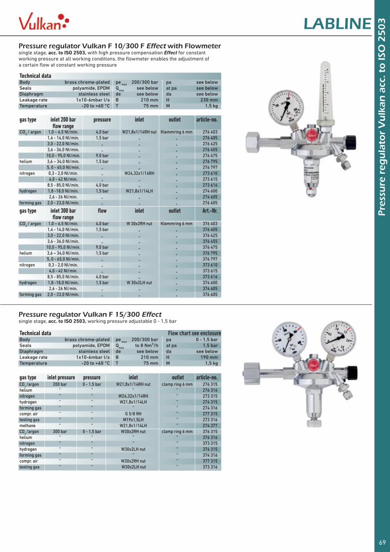
69
Pre
ssu
re r
egu
lato
r V
ulk
an a
cc. t
o IS
O 2
50
3LABLINEPressure regulator Vulkan F 10/300 F Effect with Flowmetersingle stage, acc. to ISO 2503, with high pressure compensation Effect for constant working pressure at all working conditions, the flowmeter enables the adjustment of a certain flow at constant working pressure
Pressure regulator Vulkan F 15/300 Effectsingle stage, acc. to ISO 2503, working pressure adjustable 0 - 1,5 bar
Technical data Body brass chrome-plated pe max 200/300 bar pa see belowSeals polyamide, EPDM Qmax see below at pa see belowDiaphragm stainless steel de see below da see belowLeakage rate 1x10⁻⁶mbar l/s B 210 mm H 230 mmTemperature -20 to +60 °C T 75 mm M 1,5 kg
Technical data Flow chart see enclosureBody brass chrome-plated pe max 200/300 bar pa 0 - 1,5 barSeals polyamide, EPDM Qmax to 8 Nm³/h at pa 1,5 barDiaphragm stainless steel de see below da see belowLeakage rate 1x10⁻⁶mbar l/s B 210 mm H 190 mmTemperature -20 to +60 °C T 75 mm M 1,5 kg
gas type inlet pressure pressure inlet outlet article-no.CO2 /argon 200 bar 0 - 1,5 bar W21,8x1/14RH nut clamp ring 6 mm 276 315helium ” ” ” ” 276 316nitrogen ” ” W24,32x1/14RH ” 273 315hydrogen ” ” W21,8x1/14LH ” 274 315forming gas ” ” ” ” 274 316compr. air ” ” G 5/8 RH ” 277 315testing gas ” ” M19x1,5LH ” 273 316methane ” ” W21,8x1/14LH ” 274 377CO2 /argon 300 bar 0 - 1,5 bar W30x2RH nut clamp ring 6 mm 376 315helium ” ” ” ” 376 316nitrogen ” ” ” ” 373 315hydrogen ” ” W30x2LH nut ” 374 315forming gas ” ” ” ” 374 316compr. air ” ” W30x2RH nut ” 377 315testing gas ” ” W30x2LH nut ” 373 316
gas type inlet 200 bar pressure inlet outlet article-no. flow range
gas type inlet 300 bar flow inlet outlet Art.-Nr. flow range
CO2 / argon 1,0 – 6,5 Nl/min. 4,0 bar W21,8x1/14RH nut Klemmring 6 mm 276 403 1,4 - 14,0 Nl/min. 1,5 bar „ „ 276 405 3,0 - 22,0 Nl/min. „ „ „ 276 425 3,6 - 36,0 Nl/min. „ „ „ 276 455 10,0 - 95,0 Nl/min. 9,0 bar „ „ 276 475helium 3,6 – 34,0 Nl/min. 1,5 bar „ „ 276 795 5, 0 - 65,0 Nl/min. „ „ „ 276 797nitrogen 0,3 - 2,0 Nl/min. „ W24,32x1/14RH „ 273 610 4,0 - 42 Nl/min. „ „ „ 273 615 8,5 - 85,0 Nl/min. 4,0 bar „ „ 273 616hydrogen 1,8 -18,0 Nl/min. 1,5 bar W21,8x1/14LH „ 274 600 2,6 - 26 Nl/min. „ „ „ 274 605forming gas 2,0 - 23,0 Nl/min. „ „ „ 276 605
CO2 / argon 1,0 – 6,5 Nl/min. 4,0 bar W 30x2RH nut Klemmring 6 mm 376 403 1,4 - 14,0 Nl/min. 1,5 bar „ „ 376 405 3,0 - 22,0 Nl/min. „ „ „ 376 425 3,6 - 36,0 Nl/min. „ „ „ 376 455 10,0 - 95,0 Nl/min. 9,0 bar „ „ 376 475helium 3,6 – 34,0 Nl/min. 1,5 bar „ „ 376 795 5, 0 - 65,0 Nl/min. „ „ „ 376 797nitrogen 0,3 - 2,0 Nl/min. „ „ „ 373 610 4,0 - 42 Nl/min. „ „ „ 373 615 8,5 - 85,0 Nl/min. 4,0 bar „ „ 373 616hydrogen 1,8 -18,0 Nl/min. 1,5 bar W 30x2LH nut „ 374 600 2,6 - 26 Nl/min. „ „ „ 374 605forming gas 2,0 - 23,0 Nl/min. „ „ „ 376 605
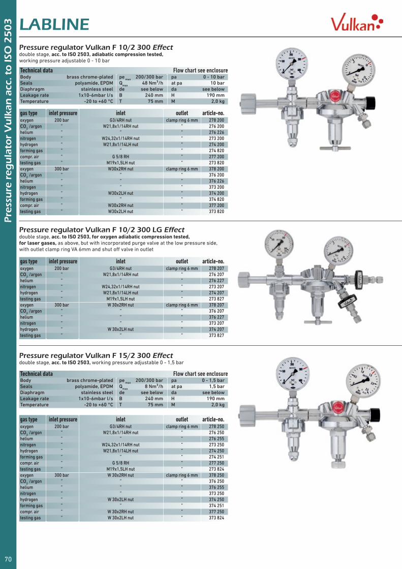
70
Pre
ssu
re r
egu
lato
r V
ulk
an a
cc. t
o IS
O 2
50
3 LABLINEPressure regulator Vulkan F 10/2 300 Effectdouble stage, acc. to ISO 2503, adiabatic compression tested, working pressure adjustable 0 - 10 bar
Pressure regulator Vulkan F 10/2 300 LG Effectdouble stage, acc. to ISO 2503, for oxygen adiabatic compression tested, for laser gases, as above, but with incorporated purge valve at the low pressure side, with outlet clamp ring VA 6mm and shut off valve in outlet
Pressure regulator Vulkan F 15/2 300 Effectdouble stage, acc. to ISO 2503, working pressure adjustable 0 - 1,5 bar
Technical data Flow chart see enclosureBody brass chrome-plated pe max 200/300 bar pa 0 - 10 barSeals polyamide, EPDM Qmax 48 Nm³/h at pa 10 barDiaphragm stainless steel de see below da see belowLeakage rate 1x10⁻⁶mbar l/s B 240 mm H 190 mmTemperature -20 to +60 °C T 75 mm M 2,0 kg
Technical data Flow chart see enclosureBody brass chrome-plated pe max 200/300 bar pa 0 - 1,5 barSeals polyamide, EPDM Qmax 8 Nm³/h at pa 1,5 barDiaphragm stainless steel de see below da see belowLeakage rate 1x10⁻⁶mbar l/s B 240 mm H 190 mmTemperature -20 to +60 °C T 75 mm M 2,0 kg
gas type inlet pressure inlet outlet article-no.oxygen 200 bar G3/4RH nut clamp ring 6 mm 278 200CO2 /argon ” W21,8x1/14RH nut ” 276 200helium ” ” ” 276 226nitrogen ” W24,32x1/14RH nut ” 273 200hydrogen ” W21,8x1/14LH nut ” 274 200forming gas ” ” ” 274 820compr. air ” G 5/8 RH ” 277 200testing gas ” M19x1,5LH nut ” 273 820oxygen 300 bar W30x2RH nut clamp ring 6 mm 378 200CO2 /argon ” ” ” 376 200helium ” ” ” 376 226nitrogen ” ” ” 373 200hydrogen ” W30x2LH nut ” 374 200forming gas ” ” ” 374 820compr. air ” W30x2RH nut ” 377 200testing gas ” W30x2LH nut ” 373 820
gas type inlet pressure inlet outlet article-no.oxygen 200 bar G3/4RH nut clamp ring 6 mm 278 250CO2 /argon ” W21,8x1/14RH nut ” 276 250helium ” ” ” 276 255nitrogen ” W24,32x1/14RH nut ” 273 250hydrogen ” W21,8x1/14LH nut ” 274 250forming gas ” ” ” 274 251compr. air ” G 5/8 RH ” 277 250testing gas ” M19x1,5LH nut ” 273 824oxygen 300 bar W 30x2RH nut clamp ring 6 mm 378 250CO2 /argon ” ” ” 376 250helium ” ” ” 376 255nitrogen ” ” ” 373 250hydrogen ” W 30x2LH nut ” 374 250forming gas ” ” ” 374 251compr. air ” W 30x2RH nut ” 377 250testing gas ” W 30x2LH nut ” 373 824
gas type inlet pressure inlet outlet article-no.oxygen 200 bar G3/4RH nut clamp ring 6 mm 278 207CO2 /argon ” W21,8x1/14RH nut ” 276 207helium ” ” ” 276 227nitrogen ” W24,32x1/14RH nut ” 273 207hydrogen ” W21,8x1/14LH nut ” 274 207testing gas ” M19x1,5LH nut ” 273 827oxygen 300 bar W 30x2RH nut clamp ring 6 mm 378 207CO2 /argon ” ” ” 376 207helium ” ” ” 376 227nitrogen ” ” ” 373 207hydrogen ” W 30x2LH nut ” 374 207testing gas ” ” ” 373 827
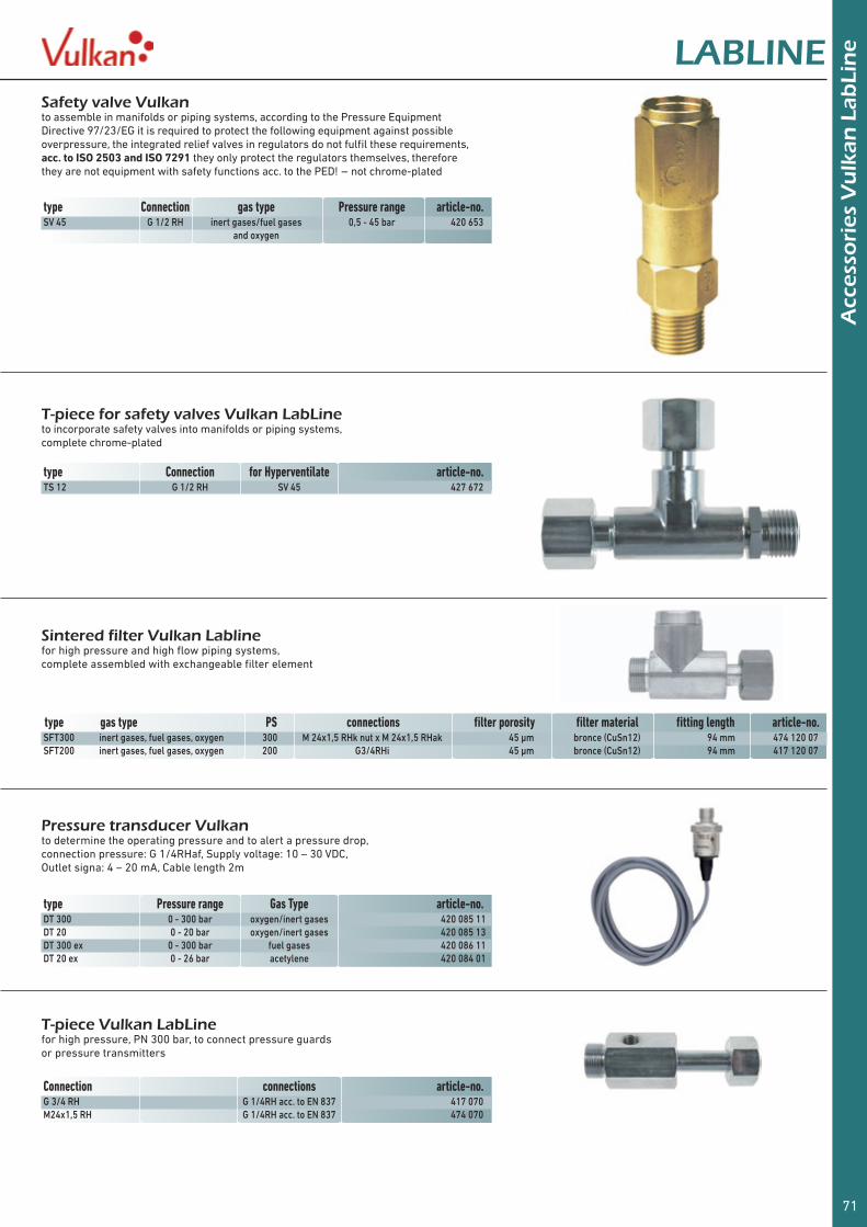
71
Acc
esso
ries
Vu
lkan
Lab
Lin
eLABLINESafety valve Vulkanto assemble in manifolds or piping systems, according to the Pressure Equipment Directive 97/23/EG it is required to protect the following equipment against possible overpressure, the integrated relief valves in regulators do not fulfil these requirements, acc. to ISO 2503 and ISO 7291 they only protect the regulators themselves, therefore they are not equipment with safety functions acc. to the PED! - not chrome-plated
T-piece for safety valves Vulkan LabLineto incorporate safety valves into manifolds or piping systems, complete chrome-plated
Sintered filter Vulkan Labline for high pressure and high flow piping systems, complete assembled with exchangeable filter element
Pressure transducer Vulkanto determine the operating pressure and to alert a pressure drop, connection pressure: G 1/4RHaf, Supply voltage: 10 – 30 VDC, Outlet signa: 4 – 20 mA, Cable length 2m
T-piece Vulkan LabLinefor high pressure, PN 300 bar, to connect pressure guards or pressure transmitters
type Connection for Hyperventilate article-no.TS 12 G 1/2 RH SV 45 427 672
type gas type PS connections filter porosity filter material fitting length article-no.SFT300 inert gases, fuel gases, oxygen 300 M 24x1,5 RHk nut x M 24x1,5 RHak 45 µm bronce (CuSn12) 94 mm 474 120 07SFT200 inert gases, fuel gases, oxygen 200 G3/4RHi 45 µm bronce (CuSn12) 94 mm 417 120 07
Connection connections article-no.G 3/4 RH G 1/4RH acc. to EN 837 417 070M24x1,5 RH G 1/4RH acc. to EN 837 474 070
type Pressure range Gas Type article-no.DT 300 0 - 300 bar oxygen/inert gases 420 085 11DT 20 0 - 20 bar oxygen/inert gases 420 085 13DT 300 ex 0 - 300 bar fuel gases 420 086 11DT 20 ex 0 - 26 bar acetylene 420 084 01
type Connection gas type Pressure range article-no.SV 45 G 1/2 RH inert gases/fuel gases 0,5 - 45 bar 420 653 and oxygen

72
Acc
esso
ries
Vu
lkan
Lab
Lin
e LABLINESafety gauge Vulkan LabLine acc. to ISO 5171with steel body Ø 63 mm
Technical data Body steel chrome-plated diameter Ø 63 mmConnection brass chrome-plated connection G 1/4 RHTemperature -20 to +60 °C acc. to ISO 5171, class 2.5
gas type pressure scale article-no.oxygen 0–300 bar 0–400/300 bar 401 092and 0–200 bar 0–315/200 bar 401 093other gases 0–100 bar 0–160/100 bar 401 043 0–60 bar 0–100/60 bar 401 086 0–40 bar 0–60/40 bar 401 027 0–20 bar 0–40/20 bar 401 014 0–10 bar 0–16/10 bar 401 094 0–6 bar 0–10/6 bar 401 044 0–4 bar 0–6/4 bar 401 098 0–2,5 bar 0–4/2,5 bar 401 049 0–1,5 bar 0–2,5/1,5 bar 401 099 0–1 bar 0–1,6/1 bar 401 096
Contact gauge Vulkan acc. to DIN EN 837-1in stainless steel body Ø 63 mm with Reed contact, also for ex area
Gauge sealsaus from aluminium 11 x 5,5 mm 11 x 5,5 mm
Technical data Body stainless steel diameter Ø 63 mmConnection stainless steel connection G 1/4 RHContact Reed type opens with falling pressureSwitch flow 10W at DC and 10VA at AC switch hysteresis 1,6% maxmax. switch voltage 24 V max. switch power 0,4 ATemperature -30 to +75 °C acc. to DIN EN 837-1, class 1.6
gas type pressure scale article-no.acetylene 0 – 26 bar 0 - 40 / 26 bar 401 103 0 – 1,5 bar 0 - 2,5 / 1,5 bar 401 107oxygen 0 - 300 bar 0 - 400 / 300 bar 401 102and 0 - 200 bar 0 - 250 / 200 bar 401 101other gases 0 – 100 bar 0 - 160 / 100 bar 401 112 0 – 40 bar 0 - 60 / 40 bar 401 108 0 – 20 bar 0 - 40 / 20 bar 401 106 0 - 10 bar 0 - 16 / 10 bar 401 110
Hand tight connections 200 bar LabLinefor hoses and regulators, to connect to Cylinder valves, chrome-plated, connections acc. to DIN 477
gas type Connection DIN 477-1 article-no.oxygen G 3/4 RH no. 9 417 845nitrogen W 24,32 x 1/14 RH no. 10 417 345inert gases W 21,8 x 1/14 RH no. 6 417 645 01fuel gases W 21,8 x 1/14 LH no. 1 417 445nitrous oxide G 3/8 RH no. 11 417 844testing gas M 19x1,5 LH no. 14 417 245
thickness packing unit article-no.1,5 mm 20 pieces 300 017 220,8 mm 40 pieces 300 018 40
Connection seals for regulators 200 and 300 bar
gas type pressure material packing unit article-no.oxygen/ 200 bar fiber material 50 pieces 300 001 50inert gases and ” polyamide 30 pieces 300 005 30fuel gases ” copper 2 pieces 410 395 12 ” PTFE 10 pieces 300 019 10acetylene 26 bar rubber 10 pieces 300 011 10testing gas 200 bar fiber material 10 pieces 300 004 10nitrous oxide 80 bar fiber material 10 pieces 300 012 10oxygen 300 bar Viton 10 pieces 911 025 10inert gases and 300 bar Viton 10 pieces 911 028 10fuel gases EPDM 10 pieces 911 025 12

73
Spar
e p
art
sets
fo
r re
gu
lato
rs a
nd
man
ifo
ldsLABLINE
Spare part sets for pressure regulators LabLine
Spare part sets for Manifold regulator LabLine
Spare part sets for In-line regulator LabLine
Spare part sets for tapping point regulators LabLine
Ersatzteilsets für Automatische Umschaltgruppen LabLine
for type range article-no.AM 35 /D/K complete for regulator and change over block high/low pressure 971 851AM 35 /DH/KH „ „ 971 853AM 45 /K „ „ 971 855AM 55 /K „ „ 971 858change over block for AM35/D/K/DH/KH only Seals high/low pressure 115 040 00 Seals and piston „ 115 042 00 Seals, piston and bush „ 115 041 00change over block for AM45/D/K 55 /D/K only Seals „ 115 040 01 Seals and piston „ 115 042 01 Seals, piston and bush „ 115 041 01In-line regulator AD 35 for AM 35 /D/K high/low pressure high/low pressure 970 128
regulator type gas type high pressure low pressure metal diaphragmF10/ F10F 200bar oxygen/inert gases/fuel gases 900218 919218F10/ F10F 200bar helium/hydrogen 90021801 919218F10/ F10F 300bar oxygen/inert gases/fuel gases 900318 919218F10/ F10F 300bar helium/hydrogen 90031801 919218F15/200 oxygen/inert gases/fuel gases 900218 919217F15/300 oxygen/inert gases/fuel gases 900318 919217F10/2 200 oxygen/inert gases/fuel gases 900228 919228F10/2 300 oxygen/inert gases/fuel gases 900328 919228F15/2 200 oxygen/inert gases/fuel gases 900227 919228F15/2 300 oxygen/inert gases/fuel gases 900327 919228
regulator type gas type high pressure low pressure metal diaphragmH10/200 oxygen/inert gases/fuel gases 900218 919218H10/200 helium/hydrogen 90021801 919218H10/300 oxygen/inert gases/fuel gases 900318 919218H10/300 helium/hydrogen 90031801 919218
regulator type gas type high pressure low pressure metal diaphragmL10 oxygen/inert gases/fuel gases 900218 919218L10 helium/hydrogen 90021801 919218L15 oxygen/inert gases/fuel gases 900208 919218L10/2 oxygen/inert gases/fuel gases 900228 919228L15/2 oxygen/inert gases/fuel gases 900227 919228
regulator type gas type high pressure low pressure metal diaphragmE10 /F oxygen / inert gases / fuel gases 910 278

74
Flo
w c
har
ts -
max
. flo
w FLOW CHARTS
table 3 Pressure regulator, in-line- and tapping point regulator
table 4 Single cylinder manifolds
table 1 Automatic manifolds Modula AM/K and KM
table 2 Pressure regulator In-line regulator
Conversion factorsAll flow data are measured with compressed air (acc. to DIN), except acetylene (measured with acetylene).Please see following conversion factors for the flow of other gases:
Gas type Chemical sign Conversion factors Gas type Chemical sign Conversion factorsargon Ar 0,85 propane C
3H
8 0,80
helium He 2,70 oxygen O2 0,95
carbon dioxide CO2 0,84 nitrogen N
2 1,00
nitrous oxide N2O 0,80 hydrogen H
2 3,80
For more information - please do not hesitate to contact us!
at inlet pressure = 2 x working pressure + 1 bar
working pressure in barworking pressure in bar
flow
in N
m3 /
h
flow
in N
m3 /
h
working pressure in barworking pressure in bar
flow
in N
m3 /
h
flow
in N
m3 /
h


We can handle pressure
High Purity Systems Reinstgastechnik
Wir können mit Druck umgehenWir geben Gas
Zentrale Gaseversorgung
Zen
trale Gaseverso
rgu
ng
Rei
nst
gas
tech
nik
Vulkan_GasTech_Montiert mit 8mm Steg.indd 101.03.15 11:56
Ask for our spearate catalogue!