Embed Size (px)
Citation preview

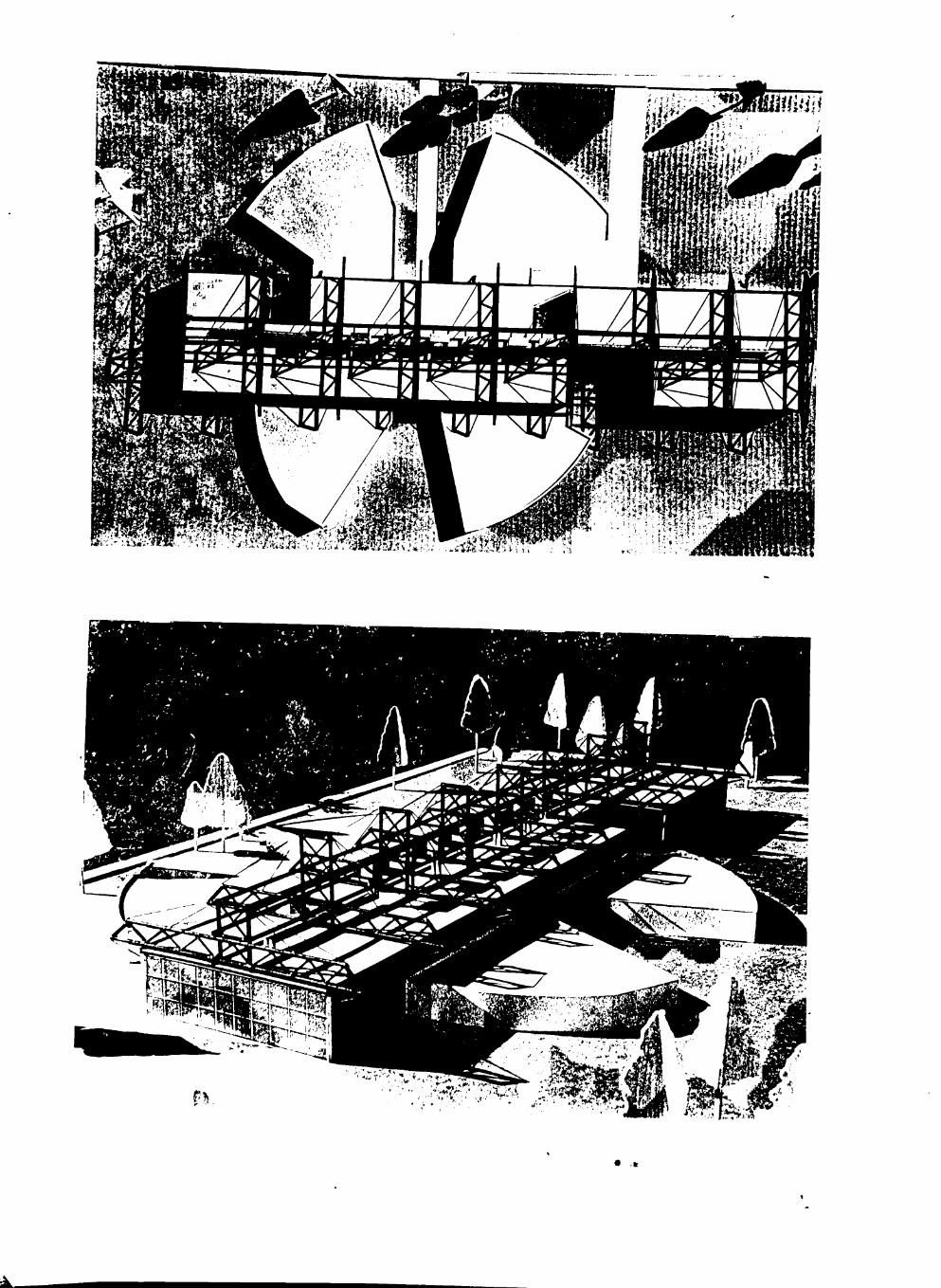
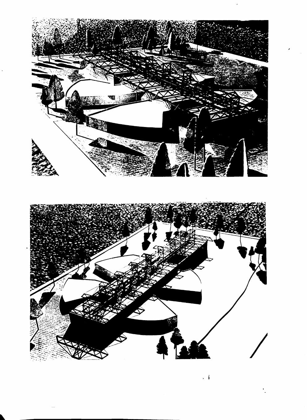
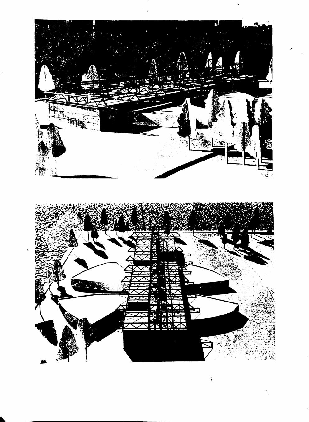
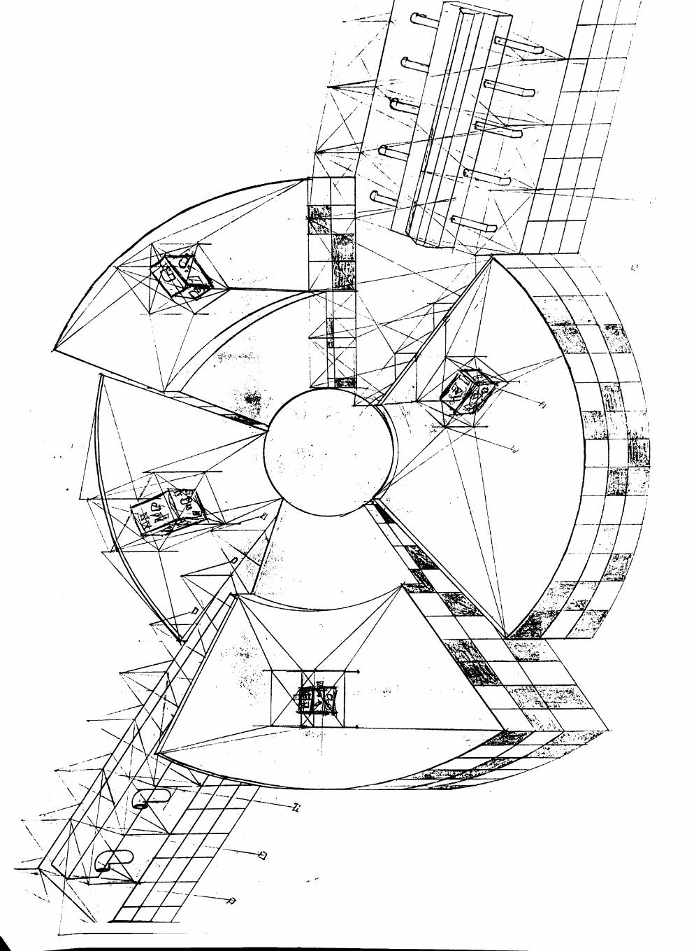
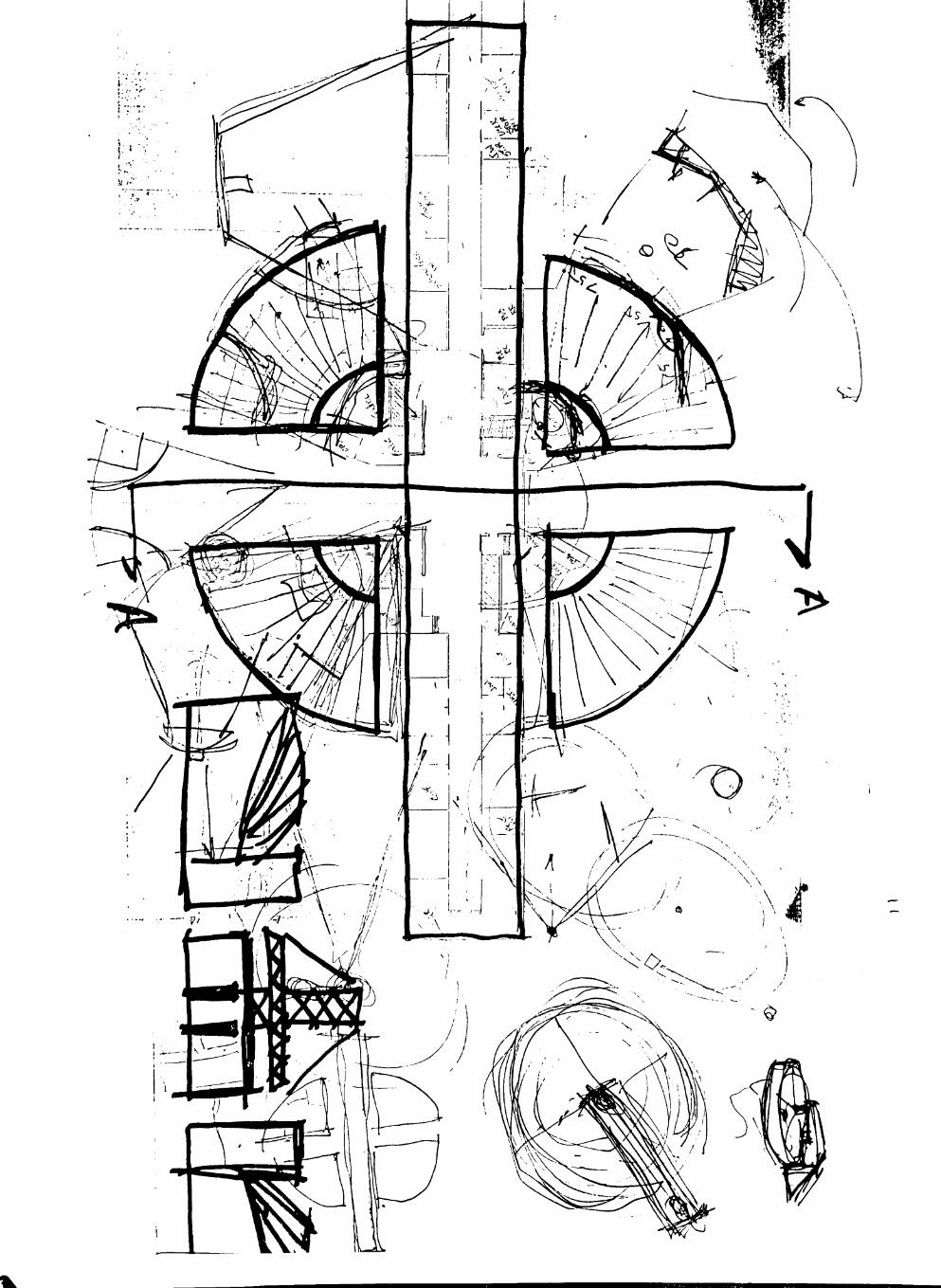
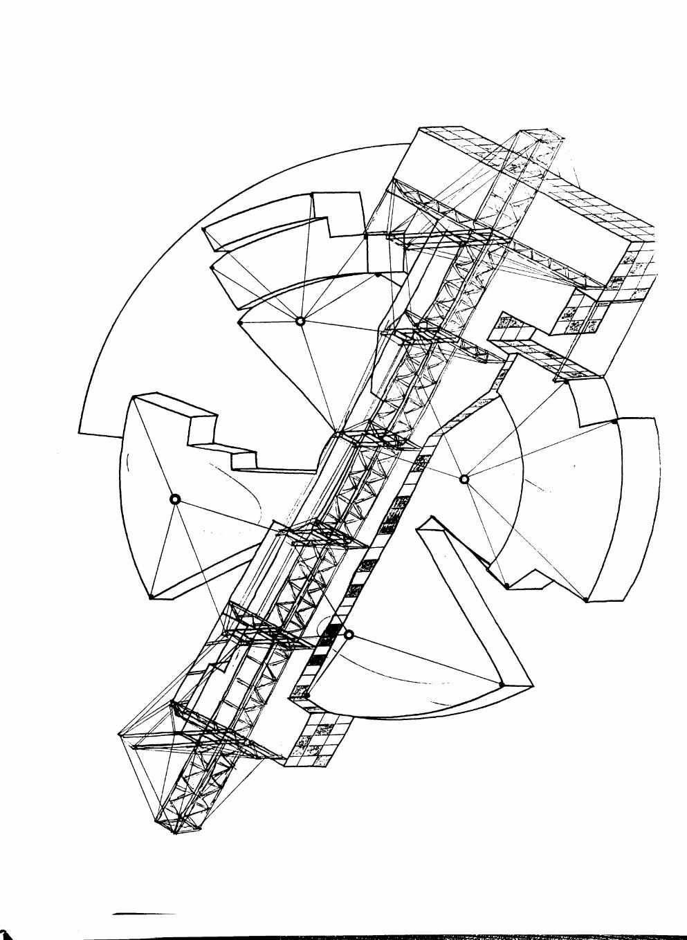
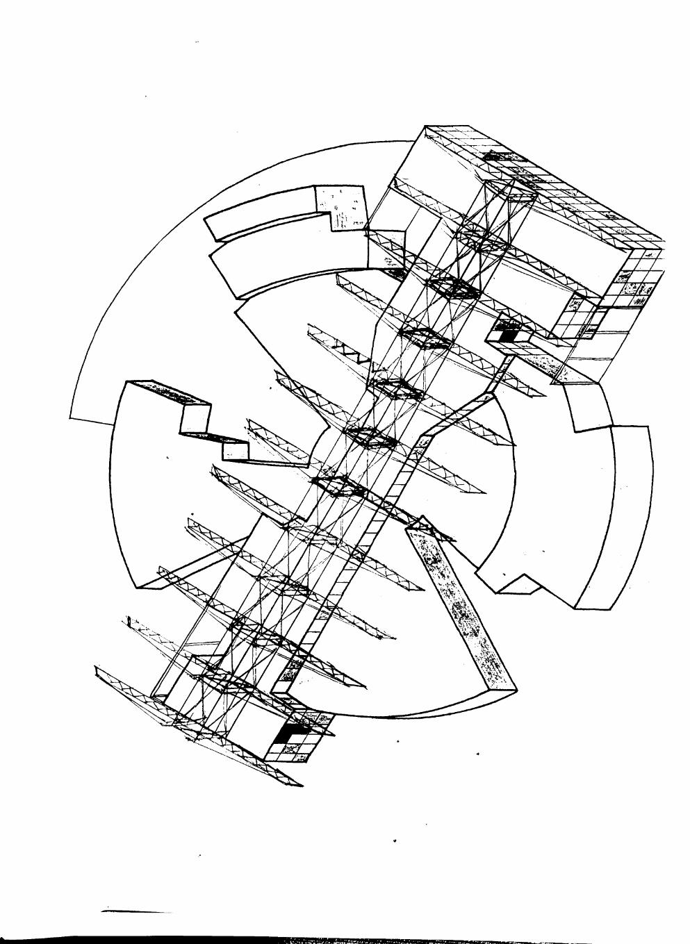
CENLA SOUND LAB RECORDING STUDIO
COMPLEX
By
James D. Knight
A THESIS
IN
ARCHITECTURE
\
Submitted to the Architecture Faculty of the College of Architecture of Texas Tech University in
Partial Fulfillment for the Degree of
CHITECTURE
Chairman of the Committee
Programming Instructor (ARCH 4395): Prof. G. Lehmann Design Critic (ARCH 4631): Prof. G. Lehmann
jan, College of Architecture
May 1989
Ft PROGRAM OUTLINE K)SZ.
, 2 ^ 1 THESIS STATEMENT / INTRODUCTION
2 BACKGROUND
A. Technical Demands B. Case Study Evaluation
3 DESIGN FOCUS
A. Technical Aspects B. Activity / Space Analysis C. Site Information
4 BIBLIOGRAPHY
5 TECHNICAL APPENDIX

THESIS STATEMENT / INTRODUCTION
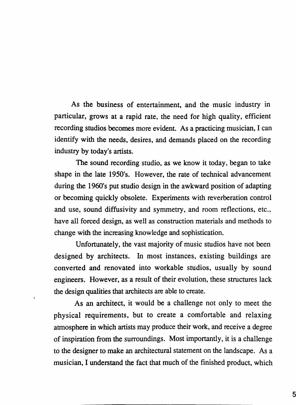
As the business of entertainment, and the music industry in
particular, grows at a rapid rale, the need for high quality, efficient
recording studios becomes more evident. As a practicing musician, I can
identify with the needs, desires, and demands placed on the recording
industry by today's artists.
The sound recording studio, as we know it today, began to take
shape in the late 1950's. However, the rate of technical advancement
during the 1960*s put studio design in the awkward position of adapting
or becoming quickly obsolete. Experiments with reverberation control
and use, sound diffusivily and symmetry, and room reflections, etc.,
have all forced design, as weU as construction materials and methods to
change with the increasing knowledge and sophistication.
Unfortunately, the vast majority of music studios have not been
designed by architects. In most instances, existing buildings are
convened and renovated into workable studios, usually by sound
engineers. However, as a result of their evolution, these structures lack
the design qualities that architects are able to create.
As an architect, it would be a challenge not only to meet the
physical requirements, but to create a comfortable and relaxing
atmosphere in which artists may produce their work, and receive a degree
of inspiration from the surroundings. Most importantly, it is a challenge
to the designer to make an architectural statement on the landscape. As a
musician, I understand the fact that much of the finished product, which
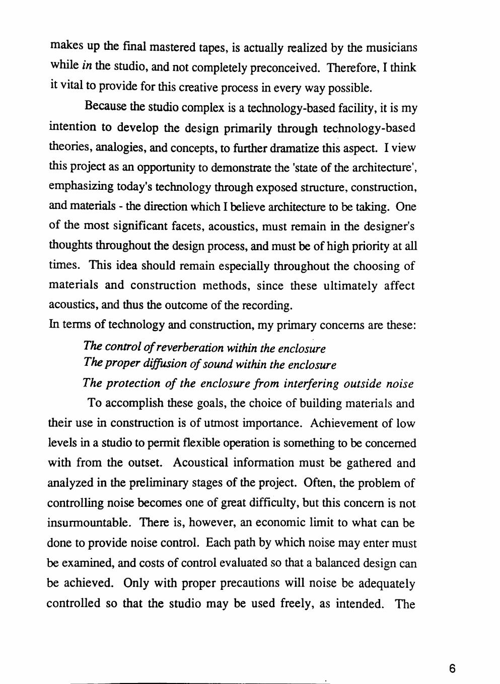
makes up the final mastered tapes, is actually realized by the musicians
while in the studio, and not completely preconceived. Therefore, I think
It vital to provide for this creative process in every way possible.
Because the studio complex is a technology-based facility, it is my
intention to develop the design primarily through technology-based
theories, analogies, and concepts, to fiirther dramatize this aspect. I view
this project as an opportunity to demonstrate the 'state of the architecture',
emphasizing today's technology through exposed structure, construction,
and materials - the direction which I believe architecture to be taking. One
of the most significant facets, acoustics, must remain in the designer's
thoughts throughout the design process, and must be of high priority at all
times. This idea should remain especially throughout the choosing of
materials and construction methods, since these ultimately affect
acoustics, and thus the outcome of the recordmg.
In terms of technology and construction, my primary concerns are these:
The control of reverberation within the enclosure The proper dijfusion of sound within the enclosure
The protection of the enclosure from interfering outside noise
To accomplish these goals, the choice of building materials and
their use in construction is of utmost importance. Achievement of low
levels in a studio to permit flexible operation is something to be concemed
with from the outset. Acoustical information must be gathered and
analyzed in the preliminary stages of the project. Often, the problem of
controlling noise becomes one of great difficulty, but this concern is not
insurmountable. There is, however, an economic limit to what can be
done to provide noise control. Each path by which noise may enter must
be examined, and costs of control evaluated so that a balanced design can
be achieved. Only with proper precautions will noise be adequately
controlled so that the studio may be used freely, as intended. The
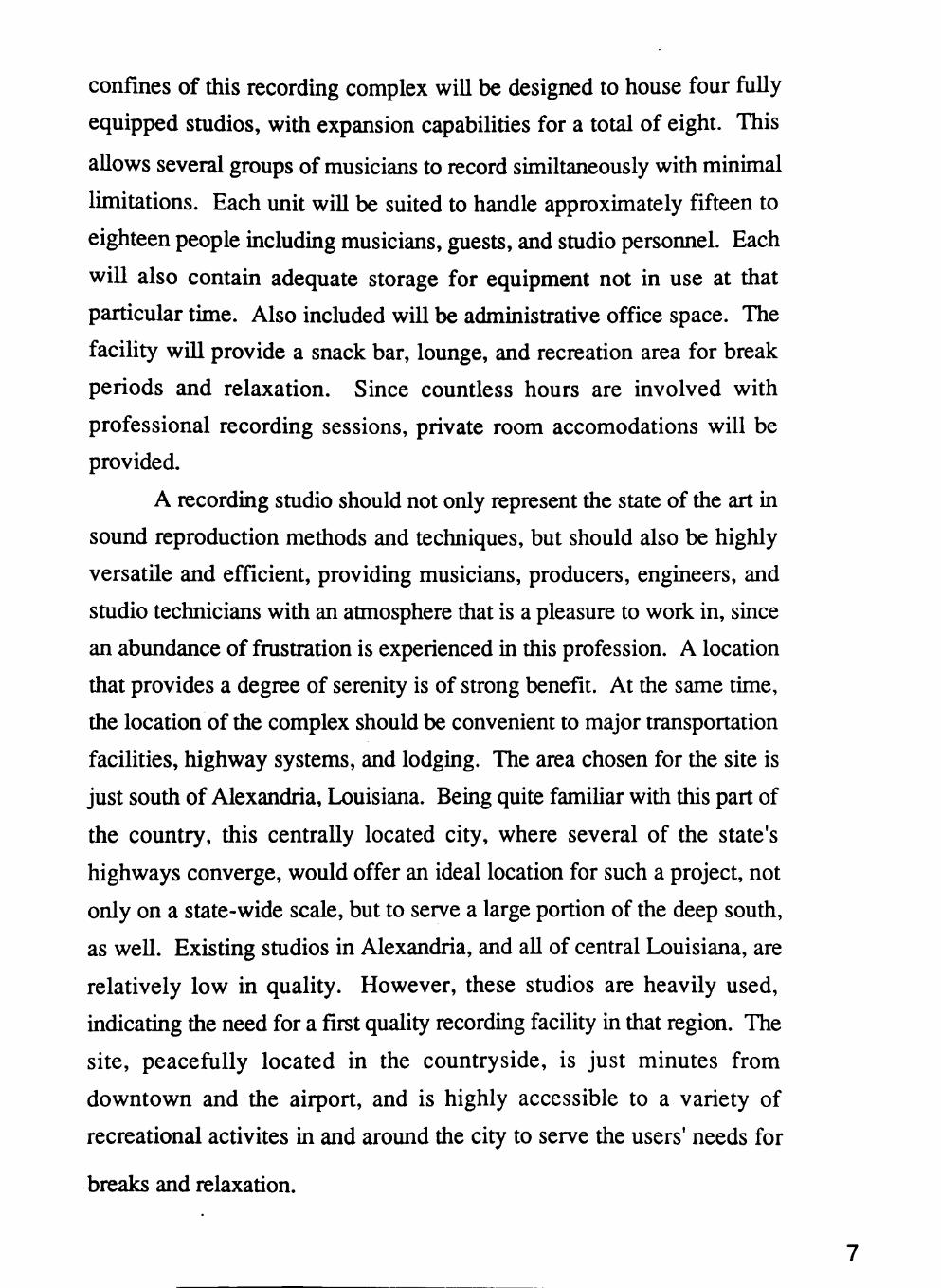
confines of this recording complex will be designed to house four fully
equipped studios, with expansion capabilities for a total of eight. This
allows several groups of musicians to record similtaneously with minimal
limitations. Each unit will be suited to handle approximately fifteen to
eighteen people including musicians, guests, and studio personnel. Each
will also contain adequate storage for equipment not in use at that
particular time. Also included will be administrative office space. The
facility will provide a snack bar, lounge, and recreation area for break
periods and relaxation. Since countless hours are involved with
professional recording sessions, private room accomodations will be
provided.
A recording studio should not only represent the state of the art in
sound reproduction methods and techniques, but should also be highly
versatile and efficient, providing musicians, producers, engineers, and
studio technicians with an atmosphere that is a pleasure to work in, since
an abundance of frustration is experienced in this profession. A location
that provides a degree of serenity is of strong benefit. At the same time,
the location of the complex should be convenient to major transportation
facilities, highway systems, and lodging. The area chosen for the site is
just south of Alexandria, Louisiana. Being quite familiar with this part of
the country, this centrally located city, where several of the state's
highways converge, would offer an ideal location for such a project, not
only on a state-wide scale, but to serve a large portion of the deep south,
as well. Existing studios in Alexandria, and all of central Louisiana, are
relatively low in quality. However, these studios are heavily used,
indicating the need for a first quality recording facility in that region. The
site, peacefully located in the countryside, is just minutes from
downtown and the airport, and is highly accessible to a variety of
recreational activites in and around the city to serve the users' needs for
breaks and relaxation.

Having a strong interest in music and the music profession, this is an
opportunity for me to create a recording complex that would serve as the
ultimate environment for completing the proposed function: Creating,
arranging, and reproducing a work of art in music.
8

BACKGROUND
lECHNICAL DEMANDS
Some have attributed it to the technological explosion in the science
of sound reproduction in the last fifteen years. Others have pointed to the
cultural revolution of the 1960's, ushered in by the likes of the Beatles
and the Rolling Stones, which made music a pivotal force in the lives of
so many. Still others have pointed to the new musicians, composers, and
writers, whose search for artistic freedom has led in directions never
considered twenty years ago.
Whatever the reason, the recording studio phenomenon is
exploding. In 1960, there were only several hundred professional
recording studios in the United States. By 1978 there were over ten times
that number. By 1984, semi-professional and home studios, which were
almost nonexistent in 1960, number an estimated 50,000.
Acoustics is the science of sound, including its production,
transmission, and effects. Although it is derived from a Greek word
meaning to hear, its meaning has been extended to include sound beyond
the limits of hearing. Acoustics is a broad field which embraces music,
radio, sound reproduction, sonar, and many other specialized subjects of
only passing interest to most architects.
Occasionally, nature provides an ideal environment for some human
activities. The architect, however, is often called upon to provide a
full-time, ideal environment to suit an activity which a man chooses to do.
A building is a controlled environment which facilitates human activity
and influences human conduct and attitudes. Sound is an integral and
10
vital part of any environment. To the architect, it is almost like a building
material - a medium which can be molded, directed, and manipulated to
create the sought after environment.
It is somewhat unfortunate that the term acoustical materials has
become a part of our technical vocabulary, since this suggests a family of
unique, specific materials with unique properties. Actually, all materials
are acoustical materials in the sense that they absorb, reflect, or ra4iate
sound, and damp vibrations. The acoustical characteristics of all materials
are as basic as their density, elasticity, or hardness. In fact, the acoustical
characteristics of materials are directly related to the basic physical
properties of the materials. This should be taken into account when a
material is considered during design.
During the past few decades, a collection of misconceptions about
acoustics and acoustical materials has been developed, even among the
technically trained. Acoustical materials are essentially transducers.
Usually they convert some of the sound energy which reaches them to
thermal energy. The reflection, transmission, radiation, and absorption
of acoustic energy by various materials constitutes essentially the whole
field of sound and vibration control.
SOUND
Sound is the sensation caused by the vibration of the ear drum.
When an object or source is caused to vibrate, a series of pressure
impulses is created in the surrounding air. As these impulses strike the
eardrum they are translated into minute electrical signals which are, in
tum, sent to the brain.
WAVES
When a source, such as a guitar string, is set into motion, the
surrounding air reacts in an elastic manner. It is altemately compressed
11
and expanded by the rapid back and forth movement of the vibrating
object. One complete cycle is called a wave.
As successful waves are formed, they travel outward in a spherical
pattem, in much the same way that water waves travel outward from a
splash.
FREQUENCY
The speed with which the waves are regularly produced is called the
frequency of vibration and is measured in cycles per second or hertz. The
length of time taken for one complete cycle is called the period of
vibration. Humans can hear frequencies in the approximate range of 20
to 20,000 Hz. This range is often referred to as the audible spectrum.
The frequency of sound is related to the pitch heard by the ear. In
general, the higher the frequency, the higher the pitch.
VELOCITY
In air, sound pressure waves travel outward from the source at
approximately 1,130 feet per second. This is commonly referred to as the
velocity of sound. This velocity varies slightly with air temperature and
humidity.
In solid materials such as wood and steel, sound travels much more
quickly (11,700 and 18,000 feet per second, respectively). These
materials are more elastic than air, which means their molecules tend to
bounce back more quickly when deflected by a sound source. The result
is that a vibrational impulse is easily sent through wood or steel,
accounting for the remarkable ability of most buildings to conduct sound
directly through their structural framework.
INTENSITY
At any given distance from a sound source, the sound wave has a
12
characteristic intensity. The intensity decreases rapidly as the wave
travels outward. Specifically, intensity diminishes according to the
square of distance traveled.
The intensity of a sound field is defined as the flow of acoustic
power, in watts, through a given area, in square meters. Thus, sound
intensity is measured in watts per square meter.
SOUND PRESSURE
Intensities of everyday sounds are extremely difficult to obtain.
They caimot be looked up on a chart or measured with a simple
instrument. This is because intensity represents a mathematical ideal
more closely than a physical quantity.
However, pressure is fortunately related to intensity and can be
measured using a relatively simple device: the microphone. Therefore,
most acoustical measurements given in decibels (dB) are actually sound
pressure levels, rather than intensity levels. The measurements are taken
with a microphone and an instrument that electrically calibrates the output
of the microphone in decibels. Such an instrument is called a sound level
meter.
THE DECIBEL
The decibel is probably the most misunderstood and misused term in
acoustics. This stems from the fact that it does not really measure a
physical quantity. The decibel merely represents a ratio between two
quantities.
As such, the decibel is used for comparing many physical quantities
whose values span a vast range. Thus, for clarification, the term dB
should be followed by an abbreviated reference, describing the quantities
being referred to. Sound pressure levels, for example, are denoted as
dB(spl).
13
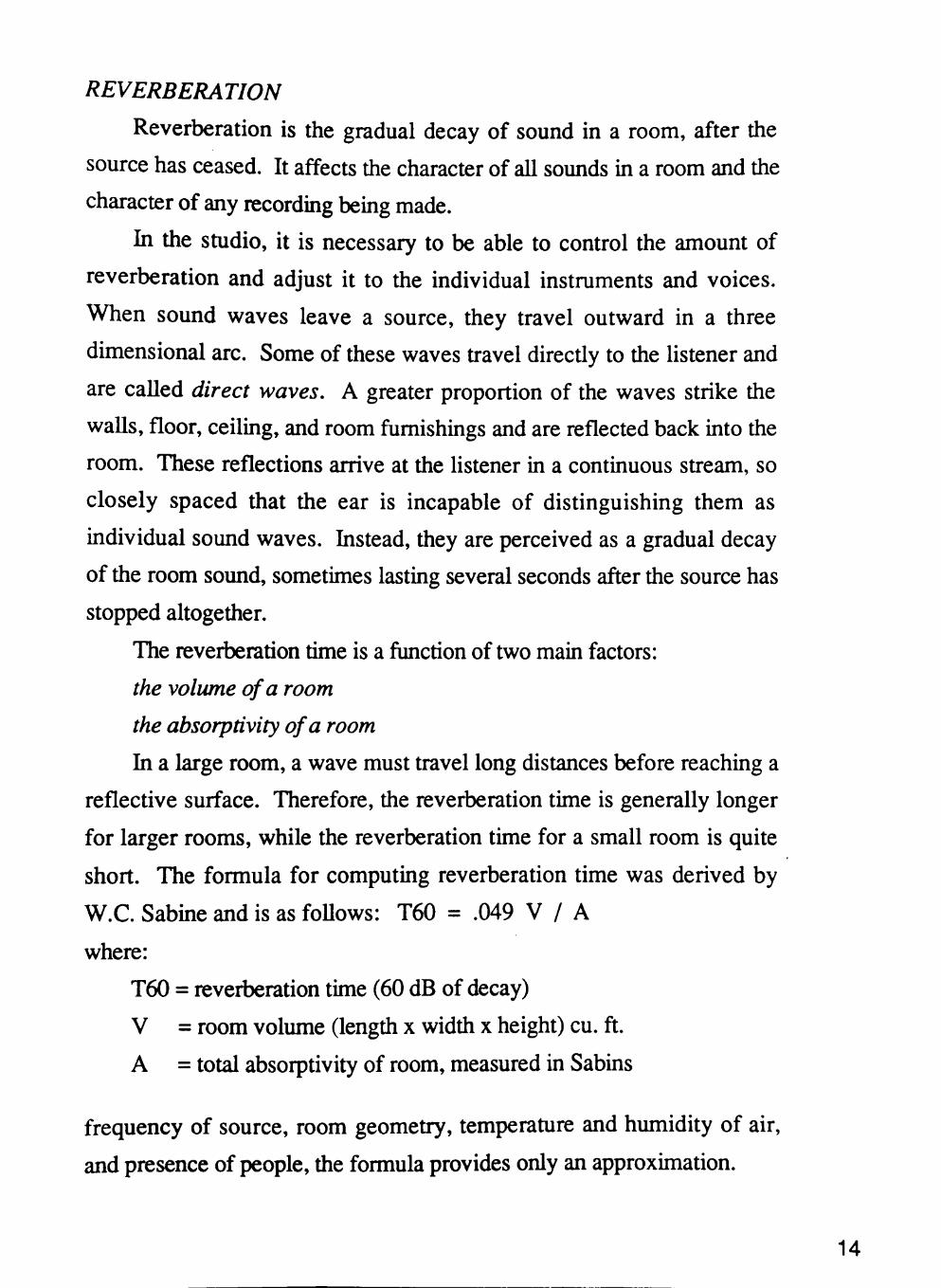
REVERBERATION
Reverberation is the gradual decay of sound in a room, after the
source has ceased. It affects the character of all sounds in a room and the
character of any recording being made.
In the studio, it is necessary to be able to control the amount of
reverberation and adjust it to the individual instruments and voices.
When sound waves leave a source, they travel outward in a three
dimensional arc. Some of these waves travel directly to the listener and
are called direct waves. A greater proportion of the waves strike the
walls, floor, ceiling, and room fumishings and are reflected back into the
room. These reflections arrive at the listener in a continuous stream, so
closely spaced that the ear is incapable of distinguishing them as
individual sound waves. Instead, they are perceived as a gradual decay
of the room sound, sometimes lasting several seconds after the source has
stopped altogether.
The reverberation time is a function of two main factors:
the volume of a room
the absorptivity of a room
In a large room, a wave must travel long distances before reaching a
reflective surface. Therefore, the reverberation time is generally longer
for larger rooms, while the reverberation time for a small room is quite
short. The formula for computing reverberation time was derived by
W.C. Sabine and is as foUows: T60 = .049 V / A
where:
T60 = reverberation time (60 dB of decay)
V = room volume (length x width x height) cu. ft.
A = total absorptivity of room, measured in Sabins
frequency of source, room geometry, temperature and humidity of air,
and presence of people, the formula provides only an approximation.
14
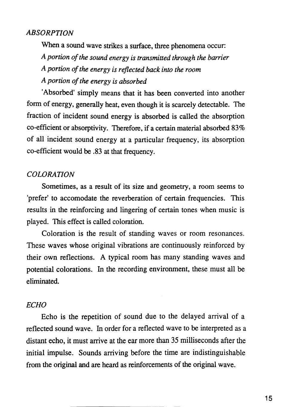
ABSORPTION
When a sound wave strikes a surface, three phenomena occur:
A portion of the sound energy is transmitted through the barrier
A portion of the energy is reflected back into the room
A portion of the energy is absorbed
'Absorbed' simply means that it has been converted into another
form of energy, generally heat, even though it is scarcely detectable. The
fraction of incident sound energy is absorbed is called the absorption
co-efficient or absorptivity. Therefore, if a certam material absorbed 83%
of all incident sound energy at a particular frequency, its absorption
co-efficient would be .83 at that frequency.
COLORATION
Sometimes, as a result of its size and geometry, a room seems to
'prefer' to accomodate the reverberation of certaui frequencies. This
results in the reinforcing and lingering of certain tones when music is
played. This effect is called coloration.
Coloration is the result of standing waves or room resonances.
These waves whose original vibrations are continuously reinforced by
their own reflections. A typical room has many standing waves and
potential colorations. In the recording environment, these must all be
eliminated.
ECHO
Echo is the repetition of sound due to the delayed arrival of a
reflected sound wave. In order for a reflected wave to be interpreted as a
distant echo, it must arrive at the ear more than 35 milliseconds after the
initial impulse. Sounds arriving before the time are indistinguishable
from the original and are heard as reinforcements of the original wave.
15
Echoes in the studio can completely ruin a recording. The most
common cause of echoes is the hard, reflective surface of the control
room window. Often, a stream of flutter echoes will set up between this
surface and other surfaces in the studio. Occasionally, only a single
reflection wiU bounce off the window and return to the microphone in the
recording area. This latter type of echo is called slapback echo. It is
crucial that both types are eliminated.
SHAPE AND CONFIGURATION
All of the surfaces which enclose a space affect the acoustics within
that space. Surfaces absorb, reflect, focus, diffuse, or diffract the sound
which reaches them. For the most part, a sound wave may be thought of
as similar to a ray of light, and optical analogies can be used to study the
behavior of sound within an enclosure.
Generally, pure geometric shapes tend to be troublesome.
Particularly dangerous are spherical, ellipsoidal, cubical, and cylindrical.
Unfortunately, architectural design tends strongly toward such shapes
under ordinary circumstances.
The dimensions of the studio are important in the relationship to the
sound quality. The smaller the studio dimensions are, the more precise
they need to be. Good reverberation characteristics depend not only on
the proper reverberation time, but also on the uniform rate of decay of
sound. These effects are achieved by the careful shaping of the studio
walls.
Small spaces normally present few difficult problems, but the
severity of acoustical problems tends to increase with the size of the
room. In small rooms, time of travel of the wave front from its source to
the listener is short. Distant echoes rarely occur, and reverberation time is
usually quite short. Although sound in small spaces may be far from
optimum, they are rarely unusable because of their intemal acoustics.
16

In large spaces, echoes, flutter, excessive reverberation,
non-uniform distribution of energy, inadequate levels in areas remote
from the source, excessive concentration in sonie areas, and similar faults
are quite common.
17
CASE STUDY EVALUATION
EXAMINATION OF ISSUES
Glass in the Studio
- the importance of using thick, double-paned glass, separated, and
angled slightly downward to send direct waves to the floor of the studio
and control room.
Lighting
- lights in the recording studio and control room should be bright
enough for visual communication, working of controls, and reading sheet
music and/or lyrics, but should not be glaring or excessive. Through the
use of track lighting and dimmers, lights should be controllable in
brightness and direction.
Studio Building Systems
- the need for using a 'floating' building system when constructing
studio walls, ceiling, and floors to prevent vibration from being
transferred from structure.
Control Room Equipment for Space Allocation
-the need for allowing space in the control room for basic required
recording equipment:
36 channel multi-track recording console
Noise reduction system
Digital reverberator
Digital delay system
18
Necessary amplifiers and monitor speakers
24 channel dolby system
Sound Screens
- the need for mobile, cylindrical screens used to provide moderately
reverberant soimd; reverse side lined with sound absorbing material and
arranged so as to not change the acoustic efficiency of the studio.
Studio Setting
- existing studio in Colorado expressing the quality atmosphere
provided by a countryside setting, away from the city and the tension
associated with it.
Isolation Booths
- when isolation booths are intended for drums, absorpant material
should be used on the lower portion of the walls for the low frequency of
the drums, while reflective material should be used on the upper portion
to maximize high frequency given by cymbols.
19

DESIGN FOCUS
20
TECHNICAL ASPECTS
Room acoustics can mean the difference between good and bad
recordings. They affect every phase of the recording process, from the
initial recording session to the final cutting of the disc.
During a recording session, room acoustics are critical. They can
cause instruments and voices to be clearly isolated, or hopelessly
muddled together in a common blur. Acoustical qualities can also have an
important secondary effect at the recording session - on the temperament
of the performers. When the acoustics are excellent, the musicians are apt
to be pleased, and will tend to perform more confidently and
enthusiastically. On the other hand, when the acoustics are poor, the
musicians are likely to feel incapable of communicating with one another
and a lack of cohesiveness may characterize the performance. Thus,
room acoustics may play into the emotional, as well as the technical
quality of a recording.
NOISE
Noise, quite simply, is unwanted sound. It is the first and most
basic element of room acoustics that affects recording. If a recording
environment is noisy, chances are the recording itself will be.
Noise can be produced by an infinite variety of sources whose only
common bond is their undesirability. Noise can never be completely
eliminated - for it is interwoven with the very fabric of our existence.
Despite this, in a recording environment, one must attempt to reduce
21
extraneous noise to its lowest possible threshold. This process is referred
to as soundproofing.
The background noise which is always present in any environment is
known as ambient noise. It can result from traffic, the operation of air
conditioners and other mechanical equipment, or much more subtle
sources such as the rustiing of trees or the falling of rain.
There are several misconceptions about ambient noise and how it is
controlled. The first is that bothersome ambient noise can be eliminated
by applying carpet, curtains, and acoustic tile to the surfaces of a room.
The truth is that these materials do very littie to stop the bulk of sound
energy from entering or leaving a room. Another common misconception
is that a room that sounds quiet to the ear has a low ambient noise level.
This is false because of the human ear's remarkable ability to reject
background noise. We seldom notice sounds which constantiy envelop
us, such as traffic, wind, or continual mechanical noise. Unfortunately, a
microphone picks up these noises immediately and transfers them to the
recording.
SOUNDPROOFING
Sound is a vibratory phenomenon. As long as the studio or control
room is rigidly connected to the immediate environment, the transfer of
sound waves and vibration to and from that environment is inevitable. As
a result, there is a point of diminishing returns beyond which further
sealing and insulation of the studio will not increase its acoustical
isolation.
By separating or floating the construction of the studio from its
immediate surroundings, we can effectively impede the transfer of sound
and vibration to and from the studio.
A floating studio is one whose walls, ceiling, and floor are separated
from the exterior architectural shell by an insulating air space. The
22
floating studio is actually an entire new room built within the existing
structure. The following sections deal with the treatment of the different
components mvolved. The details are applicable to bodi the studio and
control room construction.
WALLS
Noise transmission to and from adjacent spaces can be reduced
considerably by building floating walls separated by an air space from the
existing wall. It is important that these new walls be resilient - that is, not
rigidly connected to any part of the structure. This prevents vibrations
from being transferred from the inner walls to the outer walls, and vice
versa. This resiliency is accomplished by supporting the walls on
vibration-isolation mounting board or by hanging resilient clips. The wall
itself can be made from plywood, plaster board, gypsum drywall
material, or even masonry brick - if the structure can support the load.
The walls should completely surround the entire studio area.
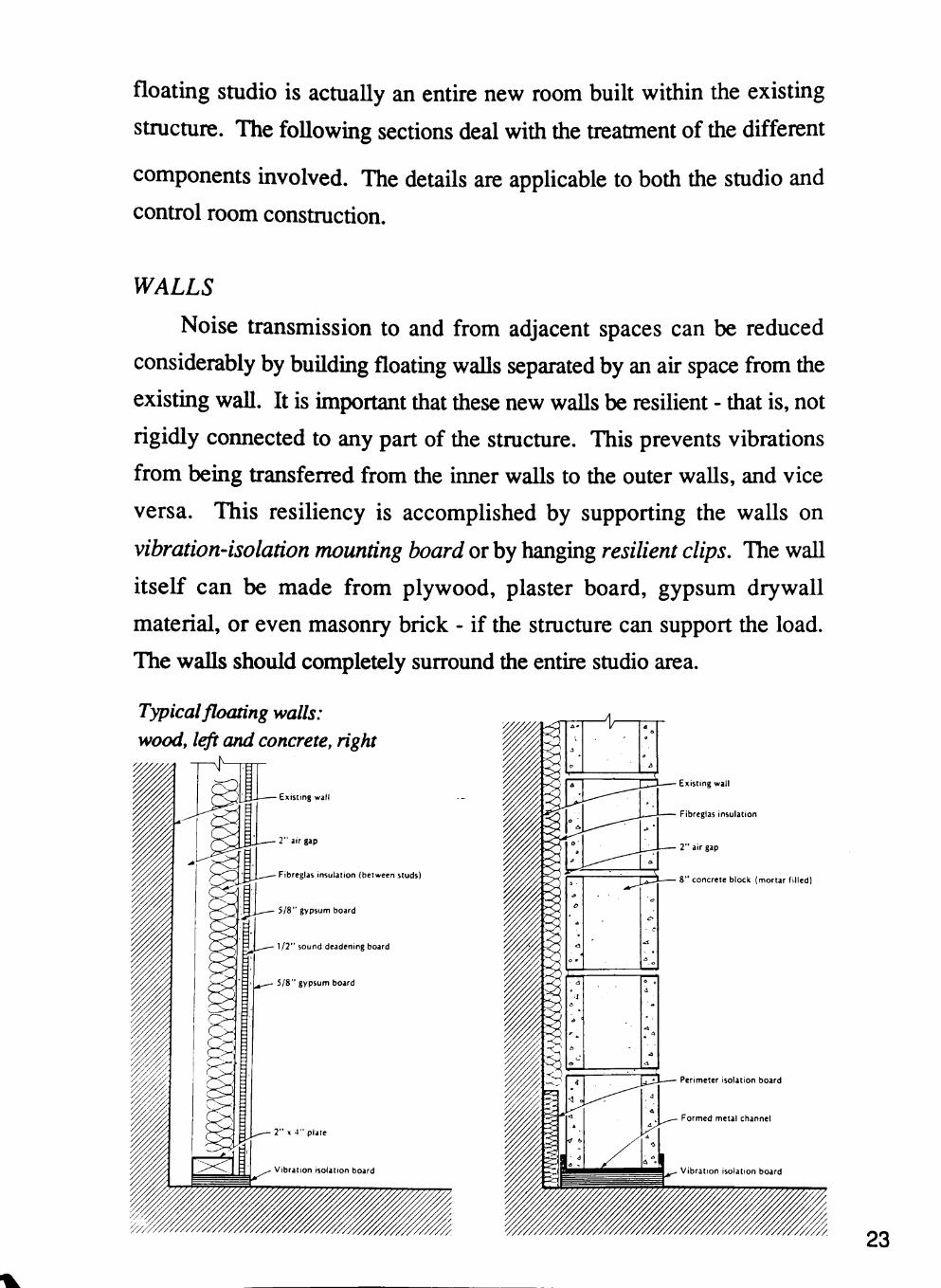
Typical floating walls: woody left and concrete, right
Existing wall
Fibreglas insulation (between studs)
\!7" sound deadening board
Existing wall
Fibreglas insulation
8" concrete block (mortar filled)
23
The floating walls should not contact the outer walls at any point.
The new walls should be caulked to eliminate any possible air leaks. The
space between the floating walls and the structure should be lined with a
porous absorbent such as fiberglas.
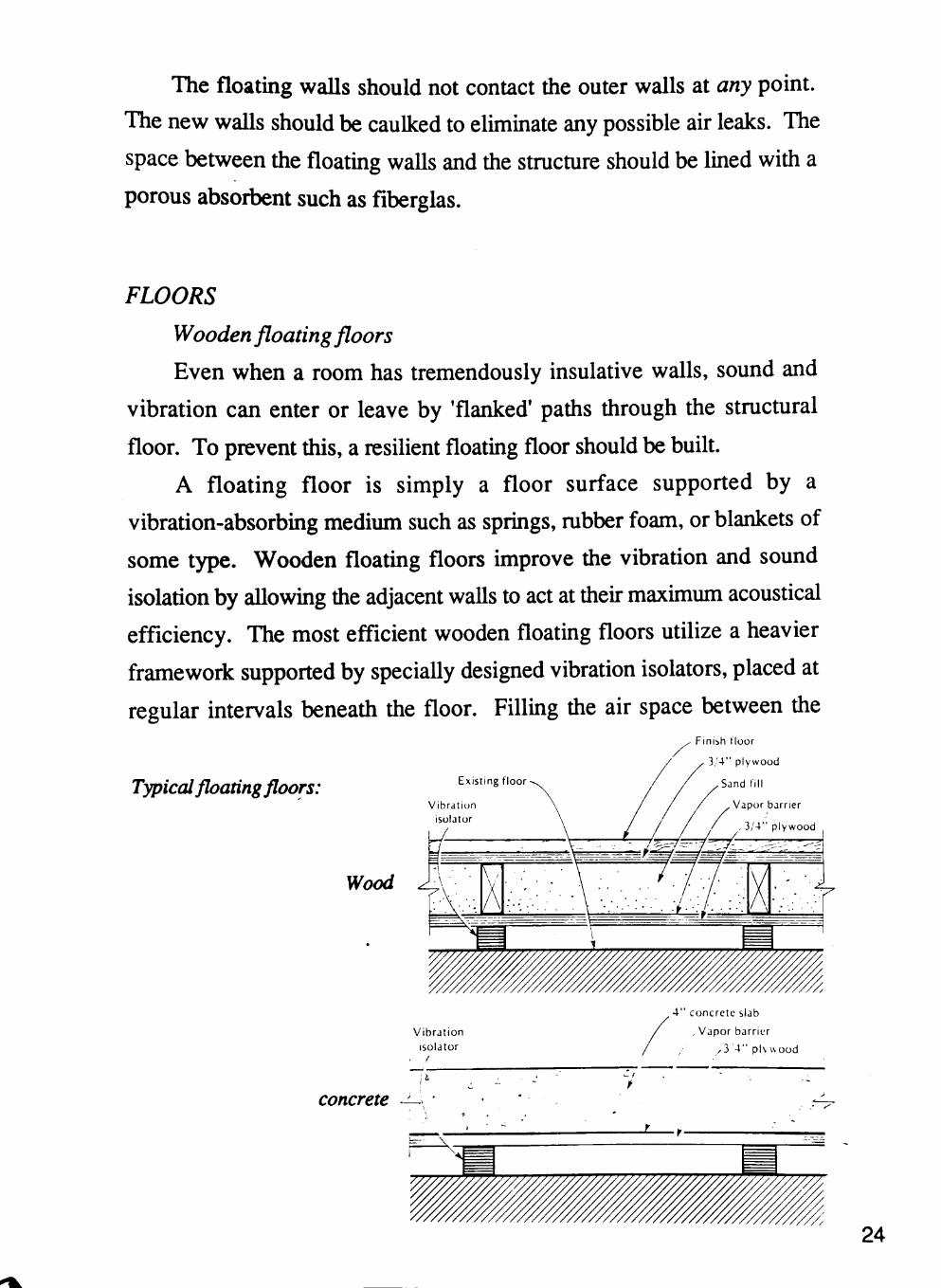
FLOORS
Wooden floating floors
Even when a room has tremendously insulative walls, sound and
vibration can enter or leave by 'flanked' paths through the structural
floor. To prevent this, a resilient floating floor should be built.
A floating floor is simply a floor surface supported by a
vibration-absorbing medium such as springs, mbber foam, or blankets of
some type. Wooden floating floors improve the vibration and sound
isolation by allowing the adjacent walls to act at their maximum acoustical
efficiency. The most efficient wooden floating floors utilize a heavier
framework supported by specially designed vibration isolators, placed at
regular intervals beneatii die floor. Filling the air space between the
Typical floating floors: Existing floor
Vibration isolator
Finish floor
3 /4" plywood
Sand fil l
Vapor barrier
, 3 /4 " plywood
y/ood
Vibra t ion isolator
, 4 " concrete slab
, Vapor barrier
, 3 4 " pK \ \ood
concrete ^ -
24
support joists with sand increases the mass of the floor substantially,
thereby increasing its isolation performance.
Concrete Floating Floors
A heavy concrete floating floor, working in conjunction with a
substantial structural slab, can eliminate virtually aU vertical transmission
of noise through the studio floor. The basic method for building and
floating a concrete floor is to support the floor at discrete pomts with very
efficient vibration isolators, thus creating a sound-attenuating air space
between the floating floor and the structural floor.
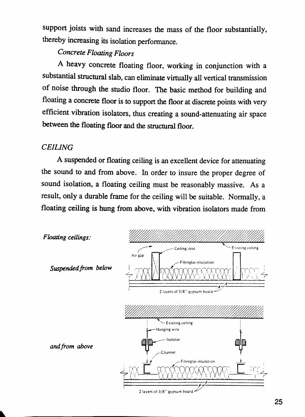
CEILING
A suspended or floating ceiling is an excellent device for attenuating
the sound to and from above. In order to insure the proper degree of
sound isolation, a floating ceiling must be reasonably massive. As a
result, only a durable frame for the ceiling will be suitable. Normally, a
floating ceiling is hung from above, with vibration isolators made from
Floating ceilings:
Suspended from below
Ceiling joist
Fibreglas insulation
Existing ceiling
ciYm:m\ur)'i 2 layers of 5/8" gypsum board
- / r •A:
and from above
Existing ceiling
i,*—Hanging wire
2 layers of 5 /8 " gypsum board
25
neoprene rubber or coiled springs. This insures resiliency and maximum
acoustical efficiency of the ceiling. The periphery of the ceiling should be
1/4 inch clear of the surrounding walls to insure that no rigid contact
occurs. The resulting air space should then be caulked tightly with a
nonhardening compound, and the space above lined with absorbent
material.
DOORS
Doors are the least massive, least airtight part of the floatmg studio's
walls. Thus, they are the weakest link in the sound transmission chain.
To alleviate this problem, each passageway leading out of a studio or
control room should have two doors - one for the inner shell and one for
the outer shell. This creates an air pocket between the doors called a
sound lock.
The larger a sound lock is, the more usable it becomes. When
properly designed, a sound lock can serve as a vocal booth or isolation
room. If properly planned, one central sound lock can take the place of
many small ones by offering access to the control room and the outside
environment, as well as to the studio.
Only solid doors should be used. Laminated double-doors or foam
lined acoustical doors are recommended. Gasketing is a must, and
door-closing hardware is important to insure a tight fit. If the doors are
outfitted with windows, only thick double panes should be used with the
air space between lined with absorptive material.
WINDOWS
Windows, like doors, are a weak link in the studio. For this reason,
strict attention to detail in window construction is of paramount
importance if the isolation of the studio is not to degenerate. It is always
26
necessary to install observation windows for the purpose of visual
communication between the engineers and performers.
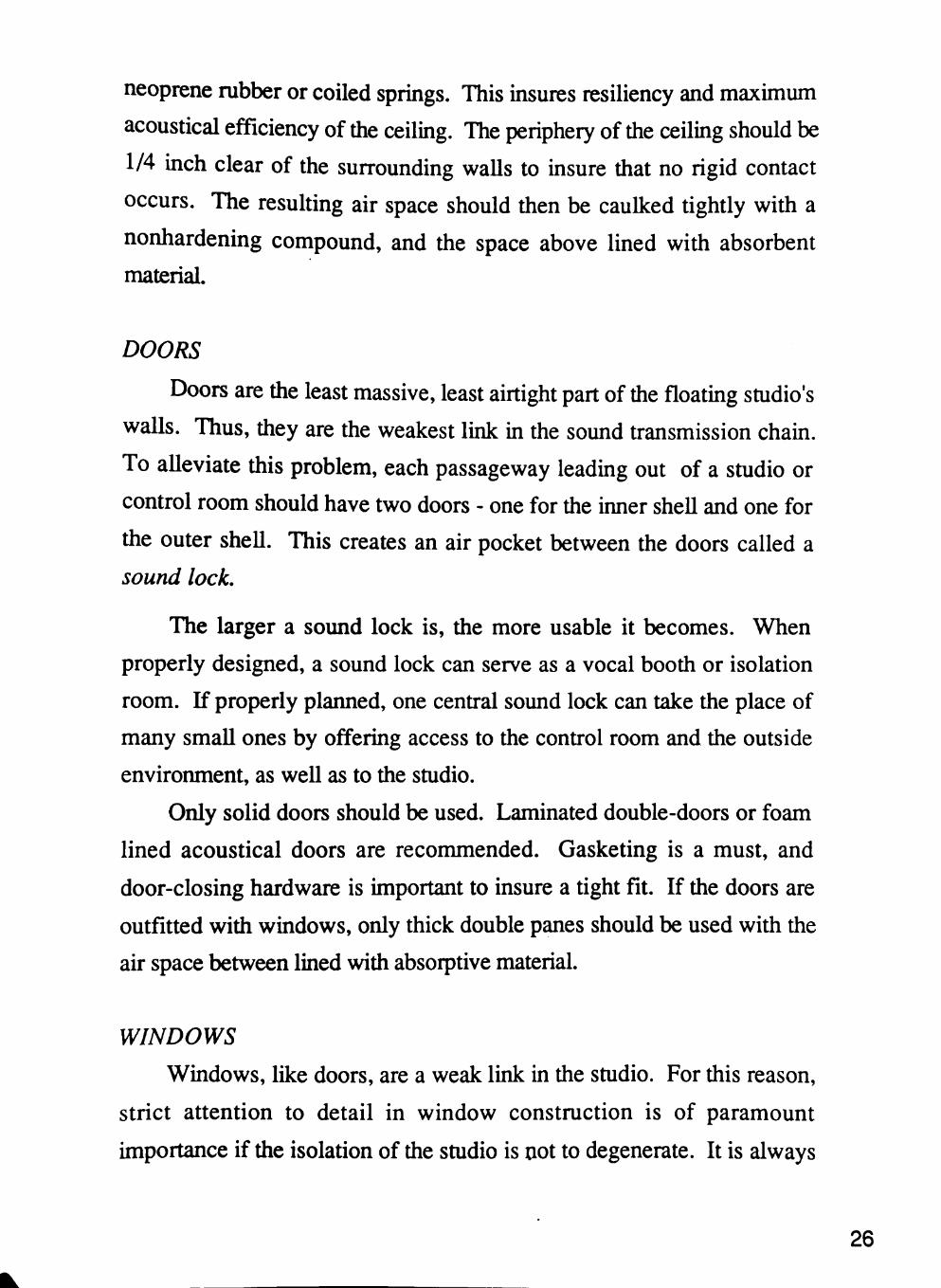
The control room window
The control room window is one of the most difficult constructions
in the studio. Visual criteria require that it be large, sometimes up to 200
Control room window detail
Isolation gap
Header beam (size according to span
Fabric over compressed fibreglas
Place compressed fibreglas over isolation gap, sprinkle
with silica gel to maintain relative humidity; cover
with fabric finish
\ ^ ^ - Maintain isolation gap
27
square feet. Unfortunately, glass is a poor sound isolator. Therefore,
control rooni windows are constructed from two or more panes.
The best results are obtained when each pane is placed in an
independent floating wall, so that sound vibration cannot be transferred
from one pane to the other by the adjacent structure. The panes should be
skewed with respect to each other and opposing walls. This measure
helps prevent the formation of flutter echoes and standing waves between
the panes.
Other windows
Very often, it is desirable to incorporate windows other than the
control room observation window into the design of the studio. For
instance, since this studio is isolated in the countryside, it may be
advantageous to open up to a view from within the studio. This type of
amenity may be quite beneficial to the look and feel of the studio, thus
making a more comfortable environment to work and create in.
Using the same construction method as previously presented,
windows to the exterior would not be a problem. It should be noted that
the presence of a large panel of reflective glass wiU influence die interior
acoustics of the studio in a manner that may not always be desirable. For
this reason, the window should be fitted with a thick curtain which can be
drawn to increase flexibility.
VENTILATION
After every effort has been made to close off the studio from the
external environment, the infihration of fresh outside air will be ahnost
completely impeded. As a result, the heat created by the lights,
musicians, and equipment will build very quickly m the air space that
surrounds the inner shell, as well as in the studio.
Installing an isolated air-conditioning and ventilation system is a
complicated matter. The problems that must be solved include:
28
Isolation of compressor and fan noise transmitted through the
building structure.
Isolation of mechanical noises transmitted through the actual
ductwork.
Elimination of air-movement noise through the duct and grill work.
Minimization of air-delivery velocity to eliminate interference with
recording microphones.
Isolation of external noise transmitted through the ductwork.
Controlling the distribution of air to the studio, control room,
isolation booths, and peripheral areas in a manner that provides for
a very responsive control of temperature and humidity under a wide
range of climactic conditions.
The solutions to tiiese problems vary, depending on the final layout
of the studio, the construction, the mechanical equipment chosen, and the
space available.
MECHANICAL EQUIPMENT NOISE AND VIBRATION CONTROL
The mechanical and electrical equipment is a source of many
acoustical problems. The choice of a heating, ventilating, or
air-conditioning system is an acoustical design decision. Nearly every
piece of mechanical equipment in a building is a source of sound and
vibration.
Noise control at the source is ordinarily the most efficient and
economical approach to this problem. Low flow velocities in ducts and
pipes, a minimum of throttling devices or abrupt changes in
cross-section, and good aerodynamic design of all elements in a system
tend to minimize acoustical problems. Any change in a process or
procedure which eluninates noise is invariably more effective than noise
control techniques to do away with acoustic energy already produced.
29
Mechanical equipment for a building is probably the most persuasive
noise problem that exists in recording studios. This results from the fact
that most people make insufficient allowance for noise control required
for a mechanical system. Considering the investment in the studio, the
extra effort involved in providing adequate mechanical system noise
reduction will be returned many times over in the usefulness of the
studio.
Probably the most straightforward item of a mechanical system
which can be controlled for noise is the fan. To provide noise control for
the fan, the ducts used to supply air to the studio and surrounding spaces
are lined either with a sound absorbing material such as fiber, or provided
with prefabricated mufflers or silencers.
LIGHTING
Proper lighting in the studio and control room is essential for the
creation of a space that is comfortable and functional. In the studio,
lighting must be powerful enough to provide musicians with the ability to
see one another, communicate, and read music or lyric sheets. On the
other hand, it must not be so excessive that it distracts or interferes with
the emotional aura of the music being recorded.
To satisfy these varying criteria, the lighting system should be
flexible. This means that the lighting fixtures should be movable and
their brightness controllable. Very often, several circuits employing a
combination of white and colored lights are used to maximize flexibility.
Dimmers can also be installed to control brightness.
Track systems, which allow the positioning of lights as well as
interchangeability of fixtures can be effective m conjunction with a fixed
lighting system. Recessed lights, which create punctures in the sound
seal, should be avoided in favor of surface-mounted fixtures. In general.
30
flourescent fixtures should be avoided in studios and control rooms
because of their tendency to induce electrical and acoustical hum.
AESTHETICS
Since the look and feel of a room can have a tremendous effect on
the behavior of the people within the room, it is no surprise that the
aesthetics of a studio often have a profound influence on the music
produced in it. Many studios have become famous for their 'sound'
which is said to be a large component of the successful records produced
in that studio. Very often, this 'sound' is a combination of acoustical
phenomena and the aesthetic presence of the studio on all musicians who
use it.
Most musicians agree that colors should not be too distracting.
Subdued colors are often effective for setting a comfortable mood. As a
rule, colors which are harmonious tend to inspire moods and music with
the same quality. Colors which are flamboyant and outrageous tend to
produce the opposite.
Natural light and views from exterior windows and skylights can
have a stimulating effect, which artificial light can never duplicate.
Natural light creates an open, airy feel in a studio that can be
tremendously inspiring. Natural light also provides an environment in
which plants and trees can flourish, giving the studio the aura of life.
31
ACTIVITY / SPACE ANALYSIS
Because of its highly specialized use, there is a very limited number
of activities which take place in a recording studio. These include band
rehearsals, sound recording, fmal mixes onto master tapes, meetings with
studio personnel, management, agents, producers, record company
representatives, etc., and periods of relaxation.
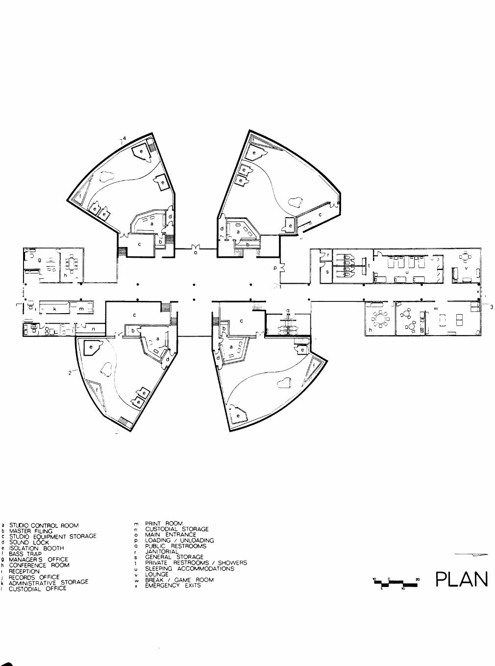
When designing the recording studio complex, the location and
relationships of the various spaces is crucial. First of all, four fully
equipped studios will be provided, each having its own control room
located adjacentiy. Other provisions include:
MASTER FILING
Storage vaults for the filing of mastered tapes will be provided
adjacent to or near the control room. These spaces must be climate
controlled due to the delicate nature and importance of the final master
recordings.
OBSERVATION AREAS
In some cases, studio observation areas will be provided for guests
to watch the recording sessions take place. While these individuals may
see into the studio, they will have no immediate access. These
observation areas will also have the capability of being closed off easily,
when necessary.
CONFERENCE ROOMS I OFFICES
Centrally located in the complex will be conference rooms to be used
for meetings by musicians, engineers, producers, press, etc., whenever
32
needed. These rooms will be designed to accommodate approximately
eighteen to twenty people.
Also located in this area will be the administrative offices for the
studio manager, chief engineer, assistant engmeers, business manager,
financial manager, and for secretarial use.
PRIVATE ROOM ACCOMMODATIONS
For the benefit of the musicians and their inmiediate staff, private
room acconmiodations will be provided. Suites with adjacent rooms
sharing shower facilities will probably be die most suitable.
LOBBY I RECEPTION
Upon entrance into the complex, the lobby and reception area will
exemplify the technology theme existing throughout the project. This area
will be highly accessible to each of the studios and their observation
areas.
BREAK I RECREATION ROOMS
For much needed time away from the business at hand, a break
room with a snack bar will be provided. Adjacent to this space will be a
recreation room featuring a variety of activities to provide musicians and
staff the opportunity to unwind.
STORAGE
An absolute neccessity to die studio's design is that of adequate and
highly accessible storages areas. These storage rooms should be climate
controlled spaces to protect delicate musical instruments and equipment
from damage. The location of these rooms should minimize the distance
that equipment must be moved and should also be arranged to serve as
sound buffers against adjacent spaces as well.
33
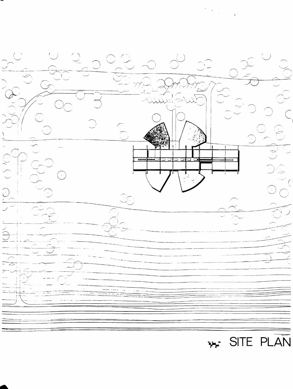
SITE INFORMATION
The location of the site and die building's orientation on diat site can
have a tremendous effect on die performance of a studio. Ambient noise
measurements can differ substantially from one part of a building to
another, depending on die proximity of traffic, mechanical equipment,
and other source noises. In general, if the choice is available, the studio
should located as far from noise producing elements as possible.
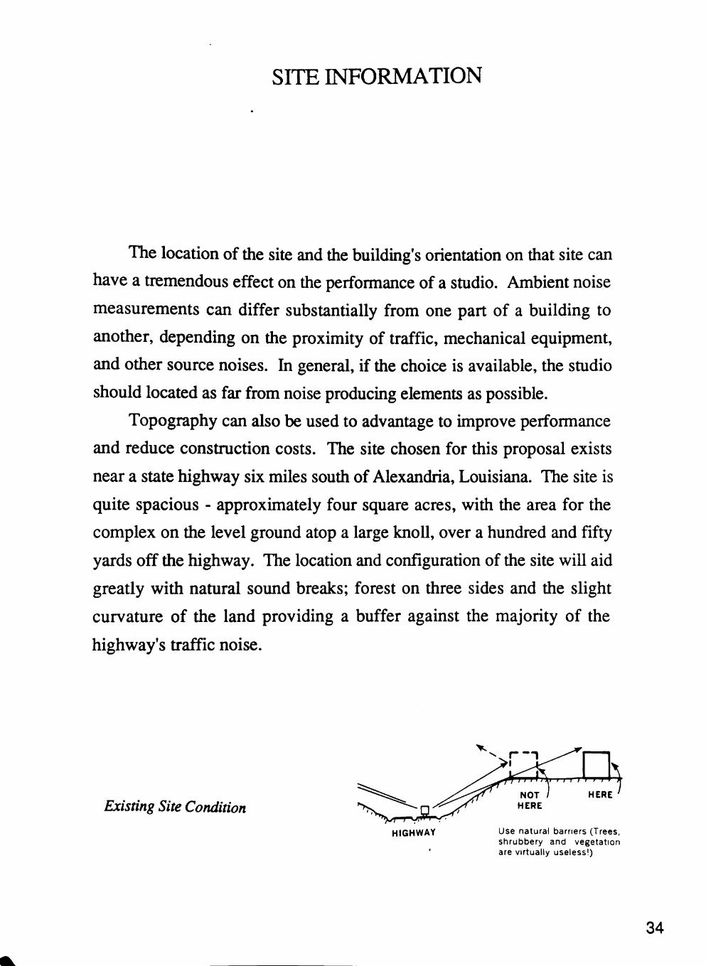
Topography can also be used to advantage to improve performance
and reduce construction costs. The site chosen for this proposal exists
near a state highway six miles south of Alexandria, Louisiana. The site is
quite spacious - approximately four square acres, with the area for the
complex on the level ground atop a large knoU, over a hundred and fifty
yards off the highway. The location and configuration of the site will aid
greatly with natural sound breaks; forest on three sides and the slight
curvature of the land providing a buffer against the majority of the
highway's traffic noise.
Existing Site Condition
HIGHWAY
HERE HERE
Use natural barriers (Trees, shrubbery and vegetation are virtually useless!)
34

35

BIBLIOGRAPHY
36
TEXTS:
Lyle F. Verges, Sound. Noise, and Vibration Control. (New York: Van Nostrand Reinhold Co., 1969).
P.H. Parkin, Acoustics. Noise, and Buildings. (London: Faber and Faber, 1979).
Harry F. Olson, Modem Sound Reproduction. (New York: Van Nostrand Reinhold Co., 1972).
G. Slot, Audio Oualitv. (New York: Drake, 1971).
Glenn D. White, The Audio Dictionary. (Seattle: University of Washington Press, 1987).
Campbell and Created, The Musician's Guide to Acoustics. (New York: Schirmer Books, 1987).
J. Backus, The Acoustical Foundations of Music. (New York: W.W. Norton and Company, 1969).
PERIODICALS:
John Borwick, "The World's First All-Digital Studio," Db-Sound Hngineering Magazine. (March/April, 1985): p. 10
S. Brewster, "Renovations at Montreal Sound," Db-Sound Hngineering Magazine. (February, 1985): p. 31
S. Caine, "Profile: Cherokee Recording Studios," Db-Sound Engineering Magazine. (May/June, 1985): p. 35
37
F.A. Everest, "Acoustic Treatment of Three Small Studios," Journal of Audio Engineering SnHPiy (July, 1968): p.307
J. Corona, "Profile: Howard Schwartz Studio," Db-Sound Engmeerinf^Mp^^yW, (July/August, 1985): p.37
S. Keene, "Tale of die Telearte Recording Studio," Sound Engineering Magazine.. (February, 1983): p.38
F.A. Everest, "Glass in die Studio," Db-Sound Engineering Magazine. (April, 1984): p. 20
M.L. Fischer, "Dallas Sound Lab," Db-Sound Engineering Magazine. (March, 1984): p. 41
M. Rettinger, "Shape of Recording Studios to Come," Journal of die Audio Engineering Societv. (April, 1980): p.237
P.B. Ostergard, "Noise Control for Studios," Joumal of the Audio Engineering Societv. (May, 1975): p.294
P.S. Penner, "Supreme Being Studios," Joumal of the Audio Engineering Society. (May, 1979): p. 249
Y. Shiraishi, "Victor Recording Studios," Joumal of the Audio Engineering Society. (May, 1971): p.405
38

TECHNICAL APPENDIX
39
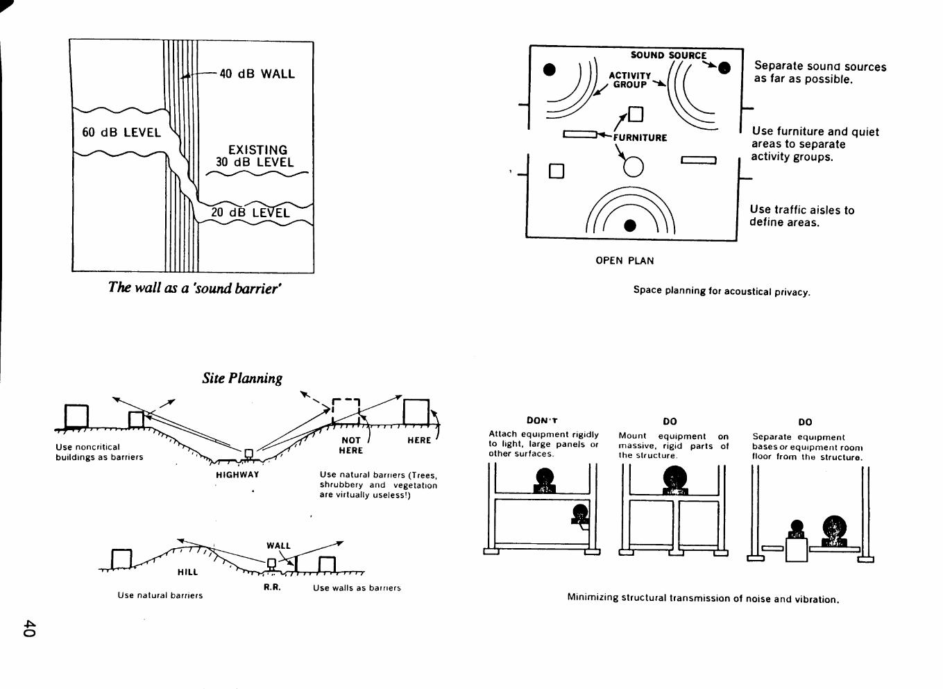
60 dB LEVEL ^
40 dB WALL
EXISTING 30 dB LEVEL
The wall as a 'sound barrier'
OPEN PLAN
Separate sound sources as far as possible.
I Use furniture and quiet areas to separate activity groups.
Use traffic aisles to define areas.
Space planning for acoustical privacy.
Use noncritic buildings as
Site Planning
HIGHWAY
Use natural barriers
Use natural barriers (Trees, shrubbery and vegetation are virtually useless!)
^r}. \^, /*! I f r I I'l I I I f
R.R. Use walls as barriers
O O N T
Attach equipment rigidly to l ight, large panels or other surfaces.
00 Mount equipment on massive, rigid parts of the structure.
JSK.
00 Separate equipment bases or equipment room floor f rom the structure.
C=l A. S.
CZ3
Minimizing structural transmission of noise and vibration.
O
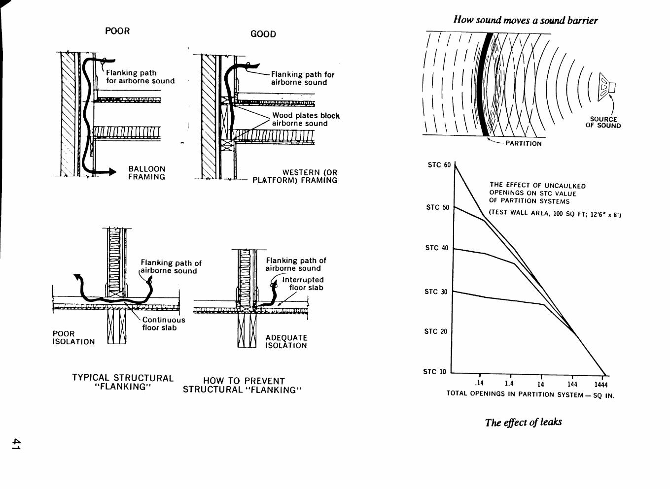
How sound moves a sound barrier POOR GOOD
Flanking path for airborne sound
n"m l"rr m^u'n:m
(III IIII III! II m i
BALLOON FRAMING
Flanking path for airborne sound
Wood plates block airborne sound
WESTERN (OR PLATFORM) FRAMING
Flanking path of airborne sound
.'juii.inu2ut
POOR ISOLATION
Continuous floor slab
Flanking path of airborne sound
Interrupted floor slab
ADEQUATE ISOLATION
"^^^'9.^Ll^t?.y.9^TV^AL HOW TO PREVENT FLANKING STRUCTURAL "FLANKING'
111 i I
STC 60
STC 50
STC 40
STC 30
STC 20
STC 10
MIW SOURCE OF SOUND
PARTITION
THE EFFECT OF UNCAULKED OPENINGS ON STC VALUE OF PARTITION SYSTEMS
(TEST WALL AREA. 100 SQ FT; 12'6' x 8')
T — r 1.4 14 144 1444
TOTAL OPENINGS IN PARTITION SYSTEIVI - SQ IN.
The ^ect of leaks
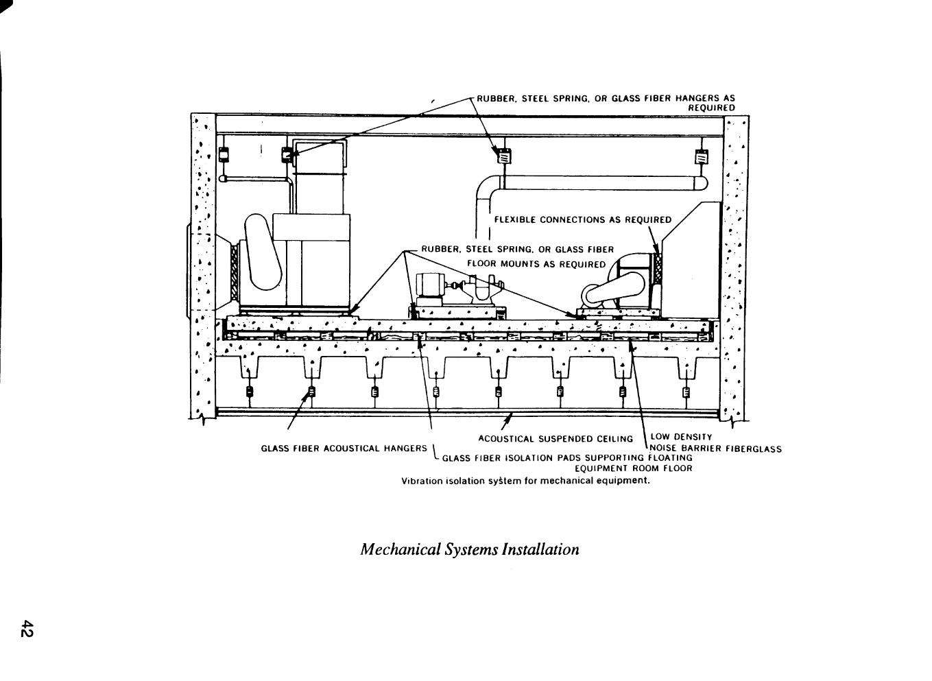
RUBBER, STEEL SPRING, OR GLASS FIBER HANGERS AS REQUIRED
ACOUSTICAL SUSPENDED CEILING \ LOW DENSITY GLASS FIBER ACOUSTICAL HANGERS \ »NOISE BARRIER FIBERGLASS
'-GLASS FIBER ISOLATION PADS SUPPORTING FLOATING EQUIPfVlENT ROOM FLOOR
Vibration isolation system for mechanical equipment.
Mechanical Systems Installation
IV)
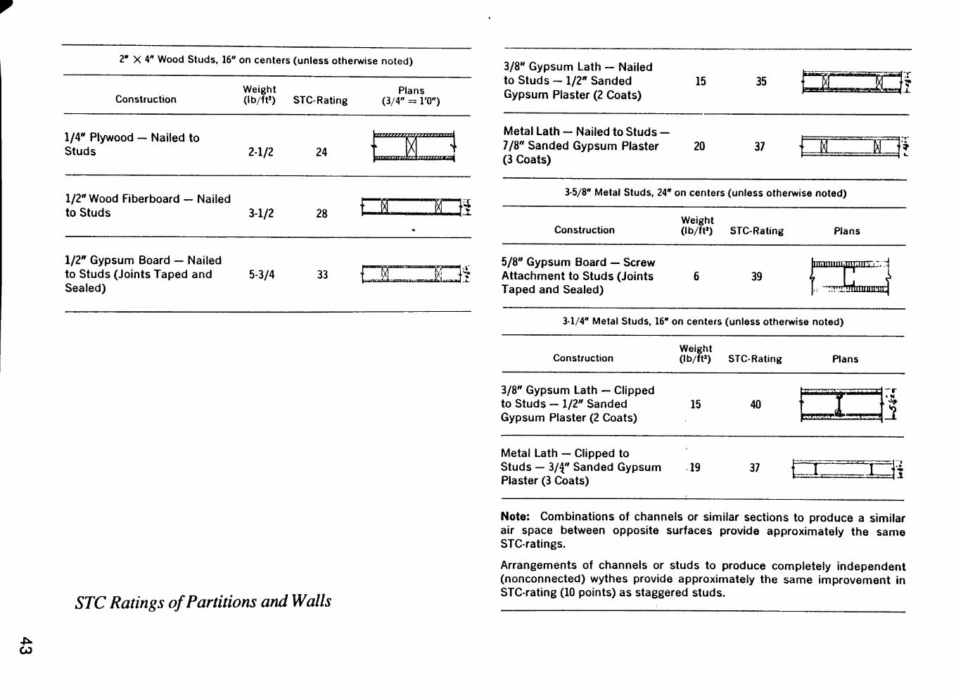
2" X 4" Wood Studs, 16" on centers (unless otherwise noted)
Construction Weight (lb/ft») STC-Rating
Plans (3/4" = I'O")
1/4" Plywood - Nailed to Studs 2-1/2 24
1/2" Wood Fiberboard - Nailed to Studs 3-1/2 28
1/2" Gypsum Board — Nailed to Studs (Joints Taped and Sealed)
5-3/4 33
szzszsazz; •nBUzzLca.
\ IlllllllltU^
S 05
{_.i<l ^L • *
3/8" Gypsum Lath - Nailed to Studs - 1/2" Sanded Gypsum Plaster (2 Coats)
15
Metal Lath - Nailed to Studs -7/S" Sanded Gypsum Plaster 20 (3 Coats)
35
37 K
3-5/8" Metal Studs, 24" on centers (unless otherwise noted)
Construction Weight (lb/ft») STC-Rating
H .,;|.
Plans
5/8" Gypsum Board — Screw Attachment to Studs (Joints Taped and Sealed)
39 ranummnnmuj/nl
3-1/4" Metal Studs, 16" on centers (unless otherwise noted)
STC Ratings of Partitions and Walls
Construction Weight (lb/ft») STC-Rating Plans
3/8" Gypsum Lath — Clipped to Studs - 1/2" Sanded Gypsum Plaster (2 Coats)
15 40 CTPWffr' I
Metal Lath — Clipped to Studs - 3/4" Sanded Gypsum 19 Plaster (3 Coats)
37 : ±
Note: Combinations of channels or similar sections to produce a similar air space between opposite surfaces provide approximately the same STC-ratings.
Arrangements of channels or studs to produce completely independent (nonconnected) wythes provide approximately the same improvement in STC-rating (10 points) as staggered studs.
CO
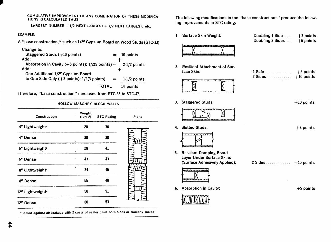
CUMULATIVE IMPROVEMENT OF ANY COMBINATION OF THESE MODIFICATIONS IS CALCULATED THUS:
LARGEST NUMBER + 1/2 NEXT LARGEST + 1/2 NEXT LARGEST, etc.
EXAMPLE:
A "base construction," such as 1/2" Gypsum Board on Wood Studs (STC-33)
Change to: Staggered Studs (+10 points) = 10 points
Add: 4-Absorption in Cavity (+5 points); 1/2(5 points) = 2-1/2 points
Add: 4-One Additional 1/2" Gypsum Board
to One Side Only (+3 points); 1/2(3 points) = 1-1/2 points
TOTAL 14 points
Therefore, "base construction" increases from STC-33 to STC-47.
HOLLOW MASONRY BLOCK WALLS
Construction Werght (lb/ft») STC-Rating Plans
4" Lightweight" 20 36
4" Dense 30 38
6" Lightweight"
6" Dense
8" Lightweight"
28 1
43
34
41
43
46
In^
tm mm 8" Dense 55 48
12" Lightweight" 50 51
12" Dense 80 53
HI
"Sealed against air leakage with 2 coats of sealer paint botti sides or similarly sealed.
The following modifications to the "base constructions" produce the following improvements in STC-rating:
1. Surface Skin Weight:
2. Resilient Attachment of Surface Skin:
rr:rrr'^'^':-• • • • » . i i '
3. Staggered Studs: " " • " ' • " • • I lllLIIIIIUIllllJIIimillllllllllJUILUll]
i i i i . i i i i i iui . l l l l l lui l l l l l l inf i i . l ini in iinimHiiii i iru
4. Slotted Studs:
- . ' ; ' i . ' d :
i I ' >
5. Resilient Damping Board Layer Under Surface Skins (Surface Adhesively Applied):
ilniiauiiui'iiiiiinfliafl
6. Absorption in Cavity:
Doubling 1 Side.. Doubling 2 Sides.
-f-3 points +5 points
ISide.. 2 Sides.
-f 6 points +10 points
+10 points
+8 points
2 Sides +10 points
+5 points
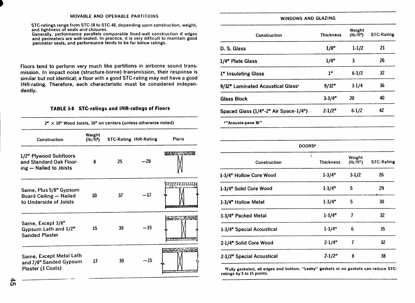
MOVABLE AND OPERABLE PARTITIONS
STC-ratings range from STC-18 to STC-48, depending upon construction, weight, and tightness of seals and closures. Generally, performance parallels comparable fixed-wall construction if edges and perimeters are well-sealed. In practice, it is very difficult to maintain good perimeter seals, and performance tends to be far below ratings.
Floors tend to perform very much like partitions in airborne sound transmission, l-n impact noise (structure-borne) transmission, their response is similar but not identical; a floor with a good STC-rating may not have a good INR-rating. Therefore, each characteristic must be considered independently.
TABLE 3-8 STC-ratings and INR-ratings off Floors
2" X 10" Wood Joists, 16" on centers (unless otherwise noted)
Construction Weight (lb/ft») STC-Rating INR-Rating Plans
1/2" Plywood Subfloors and Standard Oak Flooring — Nailed to Joists
25 - 2 8
Same, Plus 5/8" Gypsum Board Ceiling— Nailed to Underside of Joists
10 37 -17
iTf I rrrmrjrii
• •mnimiiiirtiiftllllllUUj
Same, Except 3/8" Gypsum Lath and 1/2" Sanded Plaster
15 39 -15
iviiU'iiiiU"Mi'u^pnm
Same, Except Metal Lath and 7/8" Sanded Gypsum Plaster (3 Coats)
17 39 -15
WINDOWS AND GLAZING
Construction
D. S. Glass
1/4" Plate Glass
1" Insulating Glass
9/32" Laminated Acoustical Glass'
Glass Block
Spaced Glass ( l /4"-2" Air Space-1/4")
Thickness
1/8"
1/4"
1 "
9/32"
3-3/4"
2-1/2"
Weight (lb/ft»)
1-1/2
3
6-1/2
3-1/4
20
6-1/2
STC-Rating
21
26
32
36
40
42
'"Acousta-pane 36"
DOORS''
1.
Construction
1-3/4" Hollow Core Wood
1-3/4" Solid Core Wood
1-3/4" Hollow Metal
1-3/4" Packed Metal
1-3/4" Special Acoustical
2-1/4" Solid Core Wood
2-1/2" Special Acoustical
•Tully gasketed, all edges and bottom. "Leaky" ratings by 5 to 15 points.
Thickness
1-3/4"
1-3/4"
1-3/4"
1-3/4"
1-3/4"
2-1/4"
2-1/2"
gaskets or no
Weight (lb/ft»)
3-1/2
5
5
7
6
7
8
STC-Rating
26
29
30
32
35
32
38
gaskets can reduce STC-
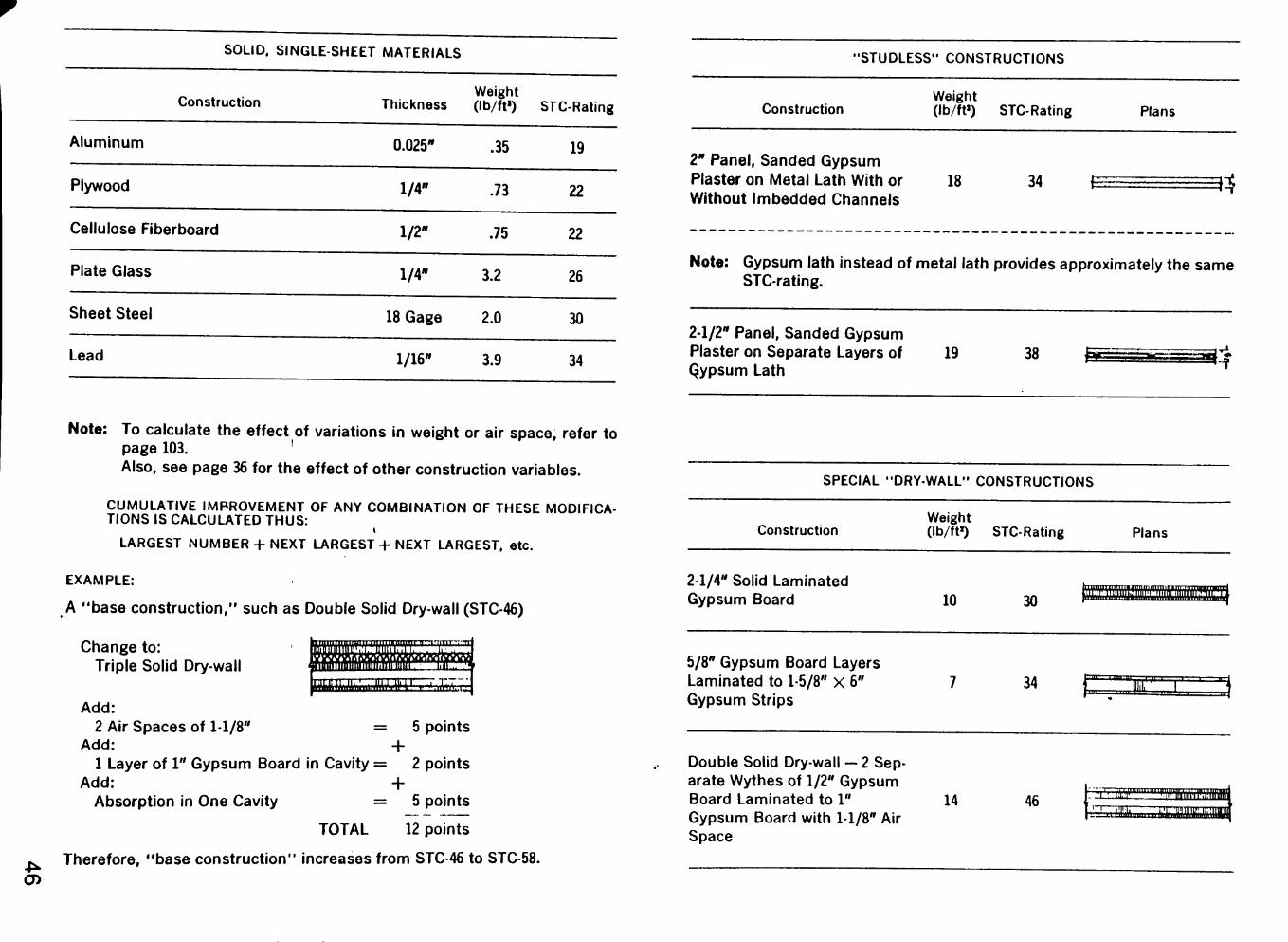
SOLID. SINGLE-SHEET MATERIALS
Construction
Aluminum
Plywood
Cellulose Fiberboard
Plate Glass
Sheet Steel
Lead
Weight Thickness (lb/ft») STC-Rating
0.025*
l/4«
1/2"
1/4"
1/16*
.35
.73
.75
3.2
18 Gage 2.0
3.9
19
22
22
26
30
34
"STUDLESS" CONSTRUCTIONS
Construction Weight (lb/ft») STC-Rating Plans
2" Panel, Sanded Gypsum Plaster on Metal Lath With or Without Imbedded Channels
18 34 ^ m
Note: Gypsum lath instead of metal lath provides approximately the same STC-rating.
2-1/2" Panel, Sanded Gypsum Plaster on Separate Layers of 19 Qypsum Lath
38
Note: To calculate the effect of variations in weight or air space, refer to page 103. ' Also, see page 36 for the effect of other construction variables.
CUMULATIVE IMPROVEMENT OF ANY COMBINATION OF THESE MODIFICATIONS IS CALCULATED THUS:
LARGEST NUMBER + NEXT LARGEST + NEXT LARGEST, etc.
EXAMPLE:
A "base construction," such as Double Solid Dry-wall (STC-46)
Change to: Triple Solid Dry-wall
Add: 2 Air Spaces of 1-1/8" = 5 points
Add: + 1 Layer of 1" Gypsum Board in Cavity = 2 points
Add: + Absorption in One Cavity = 5 points
TOTAL 12 points
Therefore, "base construction" increases from STC-46 to STC-58.
SPECIAL "DRY-WALL" CONSTRUCTIONS
Construction Weight (lb/ft») STC-Rating
2-1/4" Solid Laminated Gypsum Board
Plans
10
5/8" Gypsum Board Layers Laminated to 1-5/8" x 6" Gypsum Strips
Double Solid Dry-wall — 2 Separate Wythes of 1/2" Gypsum Board Laminated to 1" Gypsum Board with 1-1/8" Air Space
14
30
34
46
IIIWiaillltlllMIIIIUMIIIIimilMlllllMtlllW
- ^ ' ' " ' " ' l n ' . ^ -" ' • ' *
Jllll i l l l l f ^
li'i w%\ffivmm ''..^T.^> '..i,ijniirii!iiiBii
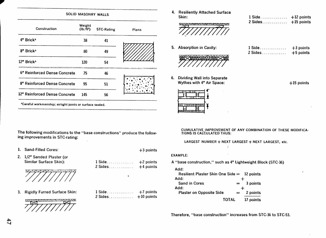
SOLID MASONRY WALLS
Construction Weight (lb/ft») STC-Rating
4" Brick" 38
8" Brick' 80
12" Brick* 120
41
49
54
6" Reinforced Dense Concrete 75 46
8" Reinforced Dense Concrete 95 51
12" Reinforced Dense Concrete 145 56
''Careful workmanship; airtight joints or surface sealed.
Plans
4. Resiliently Attached Surface Skin:
5. Absorption in Cavity:
V.'Sa •AV»V/.V#VAV/.'i»^ W
y//////7//7 6. Dividing Wall into Separate
Wythes with 4" Air Space:
t^i>:uur
:?.,;it/f:.7 Si mwmwwmmm. 'initifniitimmm
T
IS ide +12 points 2 Sides +15 points
IS ide +3 points 2 Sides +5 points
+15 points
The following modifications to the "base constructions" produce the following improvements in STC-rating:
1. Sand-Filled Cores: +3 points
2. 1/2" Sanded Plaster (or Similar Surface Skin): 1 Side +2 points
2 Sides +4 points • . . . ' v ' • • ; ' " / ' ' ' • ' • • ) • / 'j
3. Rigidly Furred Surface Skin: IS ide +7 points 2 Sides +10 points
CUMULATIVE IMPROVEMENT OF ANY COMBINATION OF THESE MODIFICATIONS IS CALCULATED THUS:
LARGEST NUMBER + NEXT LARGEST + NEXT LARGEST, etc.
EXAMPLE:
A "base construction," such as 4" Lightweight Block (STC-36)
Add: Resilient Plaster Skin One Side = 12 points
Add: + Sand in Cores = 3 points
Add: + Plaster on Opposite Side = 2 points
TOTAL 17 points
Therefore, "base construction" increases from STC-36 to STC-53. -P*-^
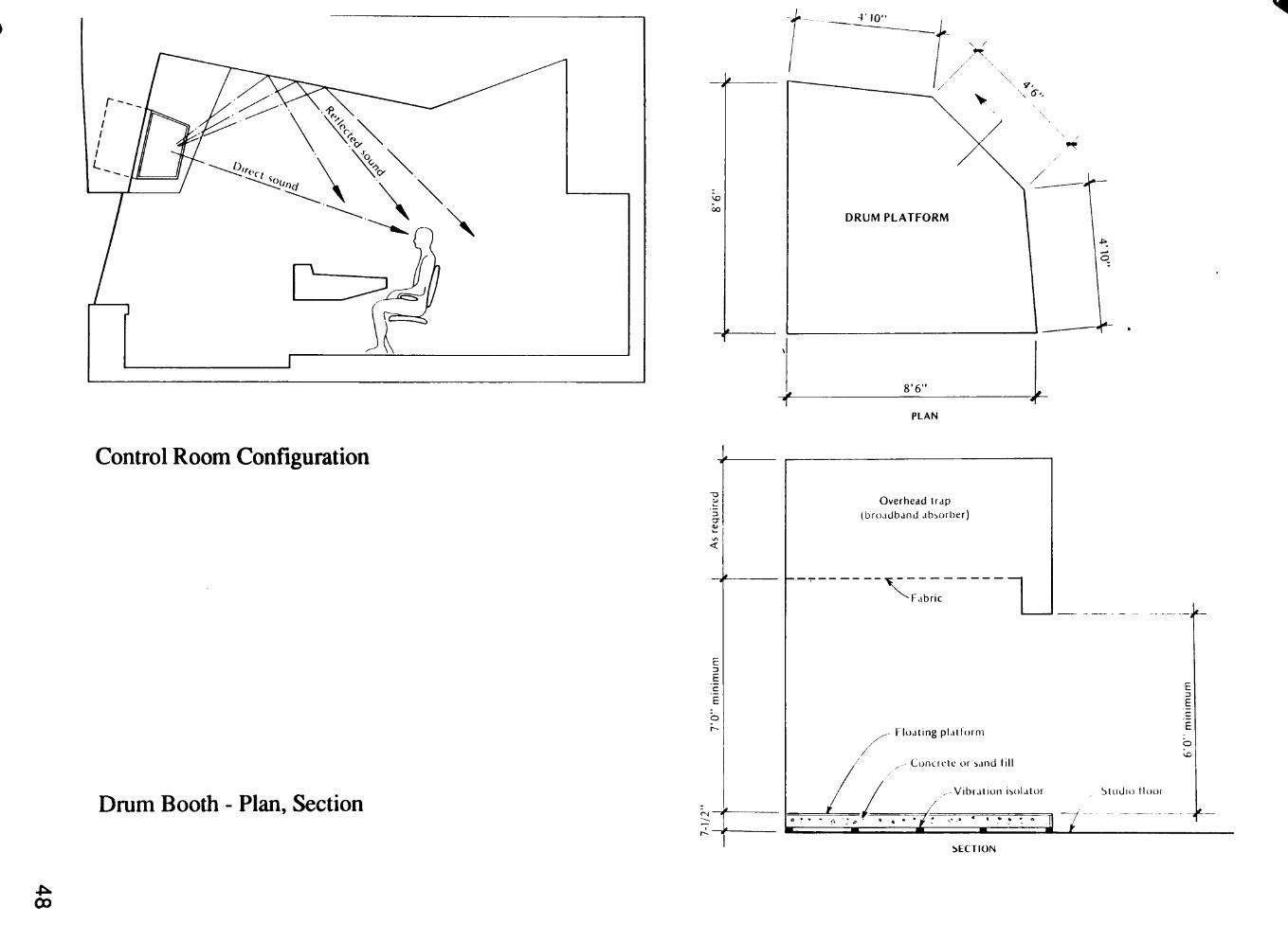
PLAN
Control Room Configuration
Drum Booth - Plan, Section
As
req
uir
ed
^ 7
'0"
min
imu
m
•1/2
r- •
f
Overhead trap (broadband absorber)
_ _ ^ F a b r i i
Floating plaltorni
^, Contrcic or sand ti l l
, Vibration isolator
o
Studio t looi
a ; .p • <» 4 » . • ^
SECTION
00
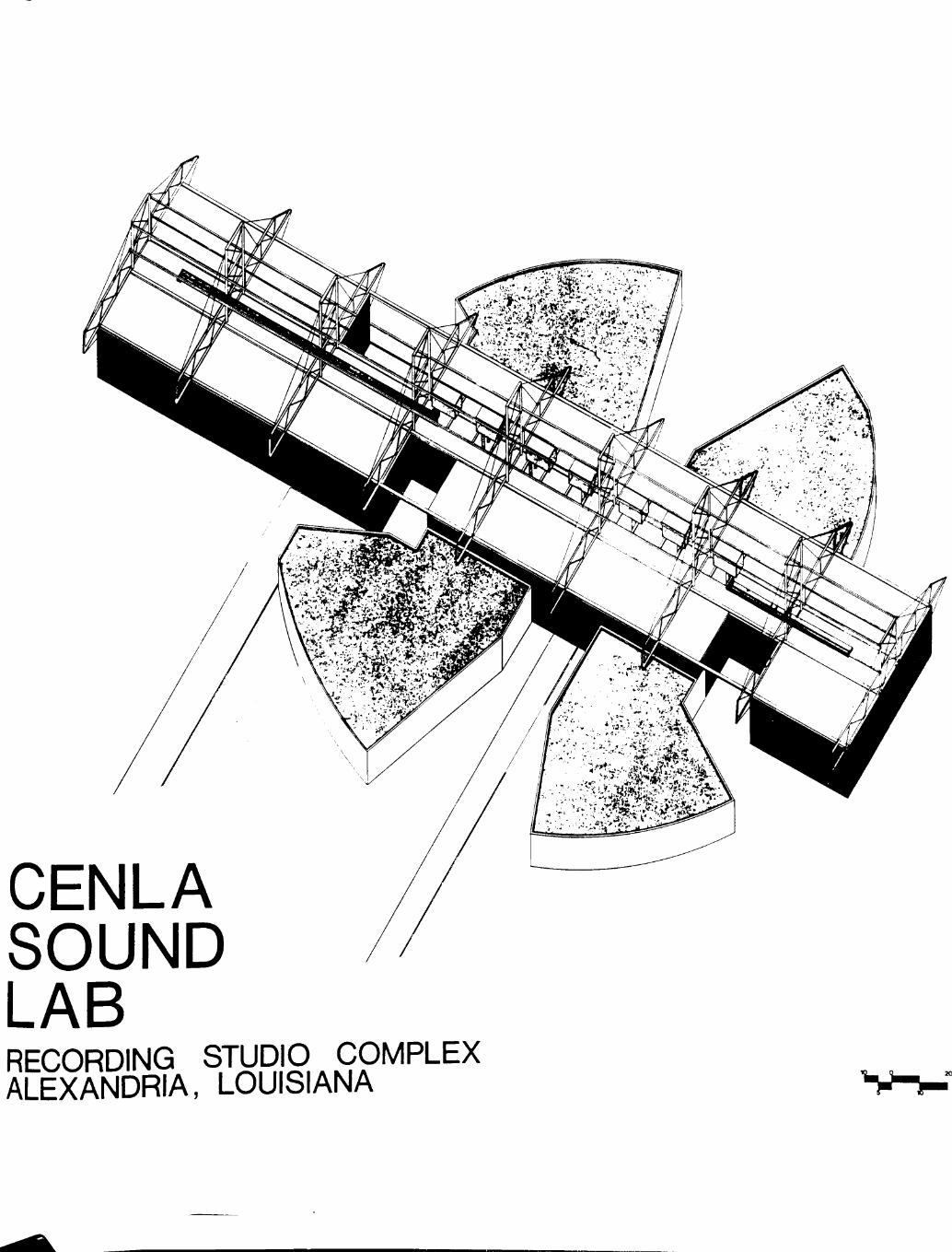
CENLA SOUND LAB RECORDING ^RIS .COMPLEX ALEXANDRIA, LOUISIANA
• >
'^r"'^-J\-' '. utj^i^^y-j^^^^mmM^^:^
w SITE PLAN
5 ^ -T
rvil
a STUDIO CONTROL ROOM b MASTER FILING c STUDIO EQUIPMENT STORAGE d SOUND LOCK e ISOLATION BOOTH f BASS TRAP g MANAGERS OFFICE h CONFERENCE ROOM I RECEPTION J RECORDS OFFICE k ADMINISTRATIVE STORAGE I CUSTODIAL OFFICE
m PRINT ROOM n CUSTODIAL STORAGE o MAIN ENTRANCE p LOADING / UNLOADING q PUBLIC RESTROOMS r JANITORIAL s GENERAL STORAGE t PRIVATE RESTROOMS / SHOWERS u SLEEPING ACCOMMODATIONS V LOUNGE w BREAK / GAME ROOM X EMERGENCY EXITS PLAN
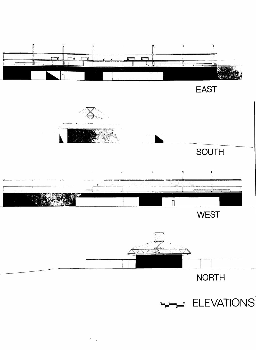
EAST
K SOUTH
WEST
NORTH
ELEVATIONS
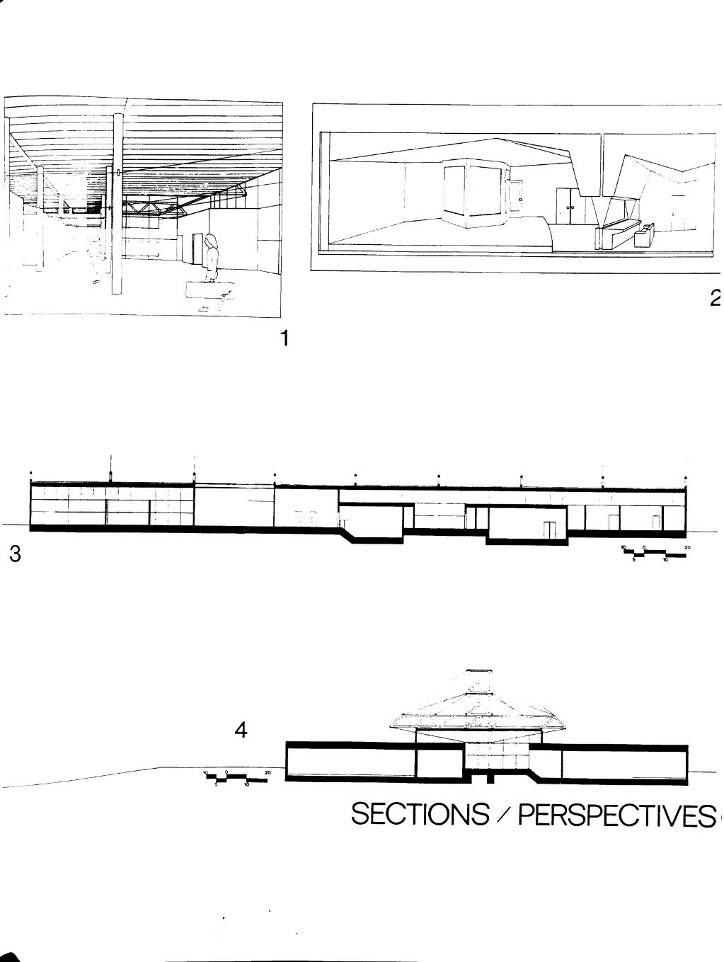
2
1
n
SECTIONS / PERSPECTIVES
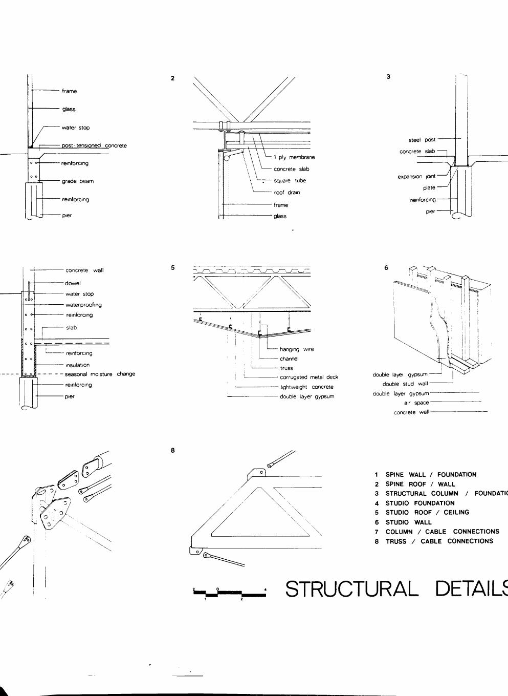
frame
glass
• water stop
post - tensioned concrete
' reinforcing
• grade beam
" reinforcing
"pier
steel post
concrete slab
expansion joint"
plate -
reinforcing -
pier-
V*
- concrete wall
• dowel
• water stop
- waterproofing
• reinforcing
• slab
O ^
- reinforcing
• insulation
seasonal moisture cfiange
• reinforcing
•pier
flanging wire
channel
truss
corrugated metal deck
lightweight concrete
double layer gypsum
double layer gypsum
double stud wall
double layer gypsum
air space
concrete wall
1 SPINE WALL / FOUNDATION
2 SPINE ROOF / WALL
3 STRUCTURAL COLUMN / FOUNDATIC
4 STUDIO FOUNDATION
5 STUDIO ROOF / CEILING
6 STUDIO WALL
7 COLUMN / CABLE CONNECTIONS 8 TRUSS / CABLE CONNECTIONS
STRUCTURAL DETAILS

mcnB
r \