Embed Size (px)
Citation preview

Quick Start Installation Guide
Copyright 2017-2019, PumpAlarm.com, All Rights Reserved
CELLULAR ALARMQuick Start Installation Guide
CELLULAR ALARM
2
To view our installation video, visit the link below.
www.pumpalarm.com/installation
Need more guidance?For technical support please call : 1-888-454-5051Hours: M-F 8a-5p EST
The following items are available to you at pumpalarm.com:
• Digital User Manual
• Installation Video
• How it Works Video
• Online Store (where you can buy additional units and accessories)
PumpAlarm.com203 W Morris St.
Indianapolis, IN 46225888-454-5051

3
Components:1. Cellular Alarm Unit2. Hose Clamps (2)3. Cable Ties (4)4. AA Batteries (4)
Optional Sensors : A. Water Sensor B. Tilt Switch C. Single Float Switch D. Dual Float Switch
*See PumpAlarm.com for our most up-to-date list of sensors.
Missing or Damaged Components?
Call PumpAlarm.com888-454-5051M-F 8:00a-5:00p EST
Do not return product to retail location.
1. 2.
3.
A. B. C. D.
4.

4
1. Status Light - Indicates the cellular status of your unit. Refer to the chart on page 29 for a description of all blink patterns.
2. Low Battery and Temperature Light - 2 red blinks indicates the backup batteries are low. If the red light is flashing, it indicates the batteries are critically low. When the green light is flashing, it indicates the Temperature Alarm. Refer to page 29 of this manual for more descriptions of blink patterns.
3. HOLD TO POWER/TAP TO MUTE - Press and hold for 3 seconds to turn on/off.
Press the button 1 time to mute the device and 1 time to unmute the device.
4. HOLD TO CONFIGURE/TAP TO TEST - Hold the Test Button to configure. Tap the Test Button to test. Press the button 1 time to test device and receive a text message.
5. Input LEDs: 1 - 2 - LEDs blink when the associated inputs 1 and 2 are triggered.
6. Input LEDs: 3 - 4 - LEDs blink when the associated inputs 3 and 4 are triggered. If using our dual float: #3 input LED blinks when the lower float is triggered and #4 blinks when the upper float is triggered. If using our sewage float: #3 input LED only blinks.
7. Sensor Input Connectors -A. Inputs 1 and 2 are 2-pin closures. Can be used with our Digital Float
Switch or Digital Water Sensor. (Can be customized for Normally Open or Normally Closed contact closures.)
B. Inputs 3 and 4 are tied together as a 3-pin closure. Can be used with our Dual Float or Sewage Float. Can be split into two 2-pin closures with additional splitter. Contact Tech Support at 1-888-454-5051 for questions about sensors or splitter option.
Getting to Know Your Device:

5
8. External Antenna Port - A coaxial connection port for our External Antenna which may be needed in some locations to boost the signal strength/reception in your basement. Refer to page 28 to learn more.
1
2
8
3
4
5
7A
67B
7
Unit Label

6
Mount the Cellular Alarm to a wall or pipe using the mounting template below. It is the correct dimensions for mounting the product. Mark the points using a pencil, then use a 3/16” drill bit to make your holes. Apply the red anchors and screws. Place Cellular Alarm on the wall.
4.56”x x
Mounting Template
Mounting Hardware and Sensors

7
Mount the device to a pipe using the hose clamps.
Hose Clamps
Connect your choice of sensor into one of the inputs on the bottom of the unit. (See page 4 for recommended sensor positions.) We suggest using our Float Switch, or Dual Float switch for sump pump applications, our Digital Water Sensor for floor or drain applications, and our Tilt Switch for aggressive sewage ejector pumps basins or any basins with iron algae build-up. For more sensor options, visit www.pumpalarm.com/sensors.

8
Please activate your unit. Visit : www.pumpalarm.com/activate. Enter the 6 digit alphanumeric unit number found on the side of the unit. Then your billing information.
This generates the phone number for your unit as well. Save this phone number as a contact in your phone.
Install (4) AA batteries by opening the battery door on the back of the unit. Align the negative (-) end of the battery to the spring in each holder.
Activate Onlinewww.pumpalarm.com/activate
PumpAlarm.com/activate
Phone #: (555)123-4567
addphoto
Cellular Alarm
LastCompany
Mobile
iPhone
(555)123-4567Side of Unit
UNITID 123ABC
1 Unit Activation and Power On
A Install Batteries

9
Plug the device into a 110V A/C outlet to power your unit on. Once the status light turns solid green, press and hold the HOLD TO CONFIGURE/TAP TO TEST button for 3 seconds. Unit will chirp twice and status light will blink red & green. This will get the unit ready to receive text messages from your cell phone. In the next step, you will configure the unit by sending it text message commands.
Solid Green Light
B Power Device On
Caller ID and Configuration ModeIf no phone numbers are configured in the unit, it will accept commands from any phone number. Once a phone number is configured in the unit, only commands from phone numbers configured in the unit will be processed.
The unit can be placed in Configure Mode by pressing and holding the HOLD TO CONFIGURE/TAP TO TEST button until the status light (top light) changes to red/green blinking. This allows the device to accept commands from any phone.

10
Your device can hold up to three phone numbers. To begin set up for phone1, use your mobile phone to create and send a text message to your device.
If you want text messages sent to additional phones, repeat this process by replacing phone1 for phone2 or phone3 followed by the mobile phone number.
phoneX [Phone Number]Space
Adding phone numbers
Phone1 5557654321
2
A
Setting up Contact Phone Numbers
Adding phone numbers
Phone2 5557656778
For your main number, which is phone1, you will send the following message; replacing 5557654321 with YOUR mobile phone number.

11
Name your unit by sending the following message, replace John Doe Residence with the name you’d like to use, up to 20 characters long:
If successful, the unit will chirp twice and you will receive a text message to the phone number you just entered. Contact our tech support team if this step is not successful.
name [Unit Name]
Name: Your AlarmPhone1: 5557654321Phone2:Phone3:
Unit Settings
Name John Doe Residence
B
Space
Name Unit3

12
If successful, the unit will chirp twice and you will receive a text message with the current settings. Contact our tech support team if this step is not successful.
Setting Up Your Temperature AlarmIf the temperature falls below the low threshold a “low temp condition” message is sent. If the temperature rises above the high threshold a “high temp conditon” message is sent. When the temperature returns to the range between the low and high thresholds, a “normal temp condition” is sent. The temperature sensor has an accuracy of +/- 5 °F.
Two degrees above or below the set thresholds are required to return to normal. Example: if the low threshold is 30°F, the temperature must go up to 32°F before it is considered to have returned to normal.
A
Name: John Doe ResidencePhone1: 5557654321Phone2:Phone3:
Unit Settings
5

13
Atemplow [°F]Space
*Use as a Heating System Alarm
We recommend setting your low temperature threshold to around 48°F and if away from the property, keep your thermostat at least 6°F warmer than you set the low threshold at to account for accuracy of sensor.
B
Send the unit a message with the following command. The 39 below should be replaced with the degrees F at which you want to have an alarm trigger.
Configuring Low Temp
TempLow 39
If successful, the unit will chirp twice and you will receive a text message with the current settings. Contact our tech support team if this step is not successful.
PwrDelay: TempLow: 39 degFTempHigh: Silent:
Setting display
14
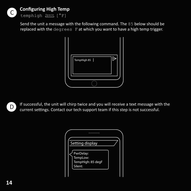
temphigh [°F]SpaceC
D
TempHigh 85
Send the unit a message with the following command. The 85 below should be replaced with the degrees F at which you want to have a high temp trigger.
Configuring High Temp
If successful, the unit will chirp twice and you will receive a text message with the current settings. Contact our tech support team if this step is not successful.
PwrDelay: TempLow: TempHigh: 85 degFSilent:
Setting display

15
Space
Space
templow none -OR- temphigh none
TempHigh none
You may want to remove the temperature alarm functionality. You can remove the high and low thresholds individually by sending either of the commands above.
Clearing Temperature
If successful, the unit will chirp twice and you will receive a text message with the current settings. Contact our tech support team if this step is not successful.
PwrDelay: TempLow: TempHigh: noneSilent:
Setting display
E
F

16
6
A
Basic configuration is now complete. Hold the HOLD TO CONFIGURE button for 5 seconds to take the device out of Configuration Mode. . The unit will chirp and stop displaying the flashing red to green pattern. Now tap the HOLD TO CONFIGURE/TAP TO TEST button on the front of the device to invoke a text message.
If successful, the unit will chirp twice and you will receive a text message with the current settings. Contact our tech support team if this step is not successful.
TEST
Testing Your Unit
John Doe Residence is operating correctly at 8:55AM on 09/23/2019
Test noti�cation
17
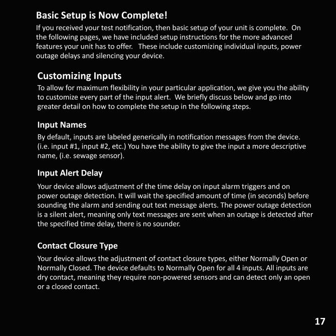
Customizing Inputs
Input NamesBy default, inputs are labeled generically in notification messages from the device. (i.e. input #1, input #2, etc.) You have the ability to give the input a more descriptive name, (i.e. sewage sensor).
Input Alert Delay Your device allows adjustment of the time delay on input alarm triggers and on power outage detection. It will wait the specified amount of time (in seconds) before sounding the alarm and sending out text message alerts. The power outage detection is a silent alert, meaning only text messages are sent when an outage is detected after the specified time delay, there is no sounder.
Contact Closure Type Your device allows the adjustment of contact closure types, either Normally Open or Normally Closed. The device defaults to Normally Open for all 4 inputs. All inputs are dry contact, meaning they require non-powered sensors and can detect only an open or a closed contact.
To allow for maximum flexibility in your particular application, we give you the ability to customize every part of the input alert. We briefly discuss below and go into greater detail on how to complete the setup in the following steps.
Basic Setup is Now Complete!If you received your test notification, then basic setup of your unit is complete. On the following pages, we have included setup instructions for the more advanced features your unit has to offer. These include customizing individual inputs, power outage delays and silencing your device.

18
Input1 �oat switch
Setting Up Your Custom Input Name
You can give the input a more descriptive name. Where the X is replaced with the input number 1,2,3, or 4, and the [input name] is replaced with your descriptive name.
Inp1: �oat switch, NO, 1 secInp2: Input 2, NO, 1 secInp3: Input 3, NO, 1 secInp4: Input 4, NO, 1 sec
Input Name
If successful, the unit will chirp twice and you will receive a text message with the current settings. Contact our tech support team if this step is not successful.
7
A
inputX [input name]Space

19
Your device allows customization of the time delay on input alarm triggers. X is either 1,2,3, or 4 for the specific input you’re trying to update.
delayX [Seconds]Space
Delay1 30
Setting Up Input Alert Delay8
Inp1: Input 1, NO, 30 secInp2: Input 2, NO, 1 secInp3: Input 3, NO, 1 secInp4: Input 4, NO, 1 sec
Input delay
If successful, the unit will chirp twice and you will receive a text message with the current settings. Contact our tech support team if this step is not successful.A
20
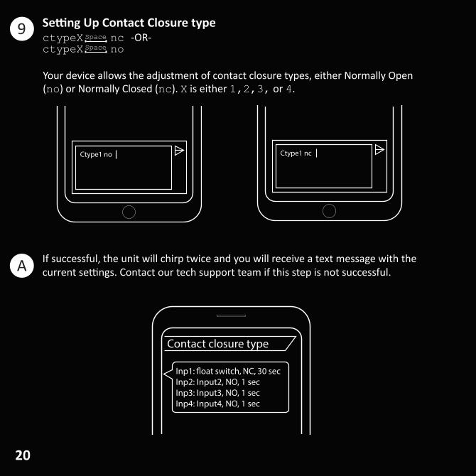
Your device allows the adjustment of contact closure types, either Normally Open (no) or Normally Closed (nc). X is either 1,2,3, or 4.
ctypeX nc -OR- ctypeX no
Space
Space
Setting Up Contact Closure type
Inp1: �oat switch, NC, 30 secInp2: Input2, NO, 1 secInp3: Input3, NO, 1 secInp4: Input4, NO, 1 sec
Contact closure type
If successful, the unit will chirp twice and you will receive a text message with the current settings. Contact our tech support team if this step is not successful.
Ctype1 no Ctype1 nc
9
A

21
Your device allows customization of the time delay on power outage detection. Send a message to your device with the following command. Replace 30 with the timeframe (in seconds) in which you want the power to be out before an alert message is sent.
NOTE: Your PumpAlarm goes to sleep to conserve the backup batteries when electrical power is lost. While sleeping, it is still monitoring but will not respond to SMS commands. If it detects an alarm condition or power has been restored, it will wake up and send text notifications as well as respond to any received commands.
pwrdelay [Secs]Space
Setting Up Power Outage Alarm Delay
If successful, the unit will chirp twice and you will receive a text message with the current settings. Contact our tech support team if this step is not successful.
PwrDelay: 30 secTempLow:TempHigh:Silent:
Power delay
PwrDelay 30
10
B

22
Tapping the Power/Mute button silences the sounder for low battery chirps and all alarm conditions. When muted the LED status light will change from solid green to flashing orange and back to solid green. Mute mode is automatically canceled after 2 hours or if an alarm state change occurs.
Silencing Alarms
Tap the Power / Mute button momentarily and release to silence sounder. Hold for longer than 3 sec and your device will power off instead of mute.

23
You can also mute your device remotely from your phone. Send the unit a message with the following command:
silent yesSpace
Silent yes
Silencing Alarms via Text Message
If successful, the unit will chirp twice and you will receive a text message with the current settings. Contact our tech support team if this step is not successful.
PwrDelay: 1 secTempLow: NONETempHigh: NONESilent: YES
Mute
24
If successful, the unit will chirp twice and you will receive a text message with the current settings. Contact our tech support team if this step is not successful.
Pump Alarm Settings:Name: John Doe Residence#1 5557654321#2#3Contractor: Mike’s PlumbingContact:
Contractor settings
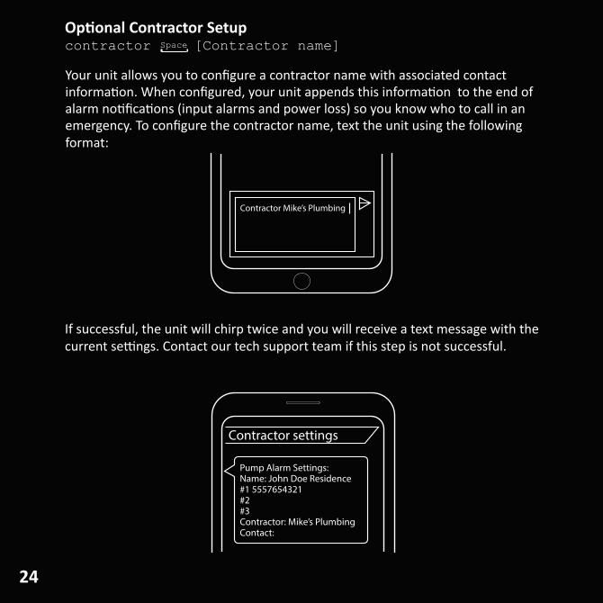
Your unit allows you to configure a contractor name with associated contact information. When configured, your unit appends this information to the end of alarm notifications (input alarms and power loss) so you know who to call in an emergency. To configure the contractor name, text the unit using the following format:
Contractor Mike’s Plumbing
Optional Contractor Setupcontractor [Contractor name]Space

25
If successful, the unit will chirp twice and you will receive a text message with the current settings. Contact our tech support team if this step is not successful.
Pump Alarm Settings:Name: John Doe Residence#1 5557654321#2#3Contractor: Mike’s PlumbingContact: 8884545051
Contractor settings
To configure the contractor’s contact phone number, text the unit using the following format:
Contact 8884545051
Spacecontact [10 digit contractor number]Setting Contractor Phone Number
26
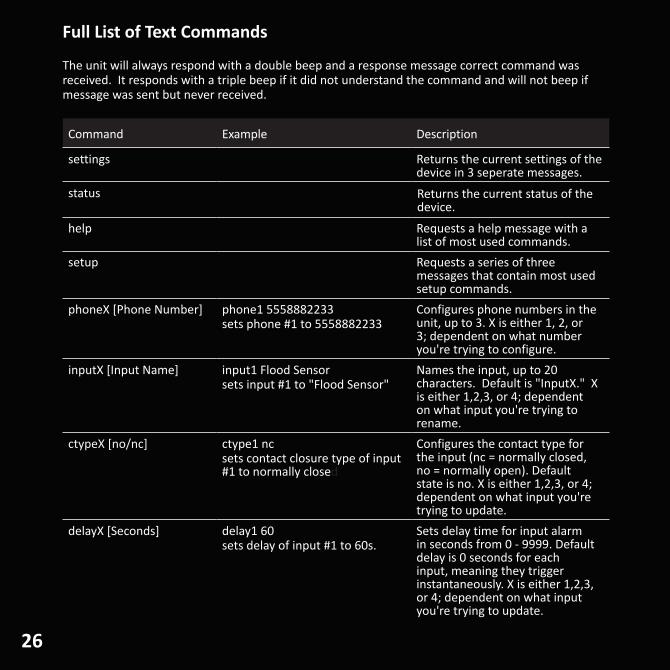
The unit will always respond with a double beep and a response message correct command was received. It responds with a triple beep if it did not understand the command and will not beep if message was sent but never received.
Command Example Description
settings Returns the current settings of the device in 3 seperate messages.
status Returns the current status of the device.
help Requests a help message with a list of most used commands.
setup Requests a series of three messages that contain most used setup commands.
phoneX [Phone Number] phone1 5558882233 sets phone #1 to 5558882233
Configures phone numbers in the unit, up to 3. X is either 1, 2, or 3; dependent on what number you're trying to configure.
inputX [Input Name] input1 Flood Sensorsets input #1 to "Flood Sensor"
Names the input, up to 20 characters. Default is "InputX." X is either 1,2,3, or 4; dependent on what input you're trying to rename.
ctypeX [no/nc] ctype1 ncsets contact closure type of input #1 to normally closed
Configures the contact type for the input (nc = normally closed, no = normally open). Default state is no. X is either 1,2,3, or 4; dependent on what input you're trying to update.
delayX [Seconds] delay1 60sets delay of input #1 to 60s.
Sets delay time for input alarm in seconds from 0 - 9999. Default delay is 0 seconds for each input, meaning they trigger instantaneously. X is either 1,2,3, or 4; dependent on what input you're trying to update.
Full List of Text Commands

27
Command Example Description
pwrdelay [Seconds] pwrdelay 30device won't send a message unless power is out for at least 30s
Sets power lost message delay in seconds from 0 - 999. Default power delay is 5 seconds. Meaning power must be out for at least 5 seconds before a text message notification is sent.
name [Device Name] name Jones Alarmsets name of device to Jones Alarm
Names the device up to 20 characters. Default name is “Your Alarm”.
test Sends a test message to all phone numbers configured in the unit.
silent [yes/no] silent yessets input alarm so that it will not beep.
Enables or disables silent mode. When enabled, unit will not beep when input triggers. Defaults to no. Cannot be overridden locally, text only feature.
templow [°F] templow 48sets low temperature threshold to 48°F.
Sets low temp alarm threshold in °F.
temphigh [°F] temphigh 99sets high temperature threshold to 99°F.
Sets high temp alarm threshold in °F.
templow none Clears low temperature alarm threshold.
temphigh none Clears high temperature alarm threshold.
contractor [Name] contractor Acme Plumbing Sets the contractor name to append to end of alarm messages, up to 20 characters.
contact [Contact Number] contact 5558001000 Sets the contractor phone number to append to end of alarm messages, up to 14 characters.
sponsor [Sponsor Name] sponsor Acme Insurance Sets the sponsor name to append to end of alarm messages, up to 25 characters. Contractor settings override sponsor messages.

28
Audible Alarms
Alert Event Type
(1) 1sec Beep on/off toggle Input alarm activated
(1) 1sec Beep Power on (after activation)
(1) 1/4sec Beep Every 30S Battery low or critically low
(1) 1sec Beep Push to test
(2) Chirps Successful programming
(5) Chirps Cellular service or transmission error
(3) 1/4 sec Beeps Incorrect or unsuccessful programming error
Your unit will warn you when there is a problem detected. Use the chart below to determine your audible alarms.
Signal Strength Guide
Where Signal is Status Corrective Action(s)
-40 dB to -99 dB OK None
-100 dB to -113 dB WEAK Make sure device is not near foundation wall or an area that can restrict cellular signal. Move to another location where better cellular signal is available.
> -113 dB NONE The device is not able to send or receive alert messages. Move device to a location that can connect with the cellular towers.
In some cases it will be necessary to boost the signal strength/reception in your basement to install or activate the device. One option for increasing signal strength is to purchase an external antenna. Visit www.pumpalarm.com /sensors to learn more. Below are the ranges of cellular signal strength you may encounter (in dB) during setup. If there is a problem connecting to the network, or the device will not stay connected, refer to the chart above to diagnose the problem.
Recommended signal range for optimal performance should be between -40 dB and -99 dB.
For a full list of Technical Specifications, visit the product page at store.pumpalarm.com

29
Battery / Temp LED
Off Batteries normal
Flashing Red Batteries low or critically low
Flashing Green Once Low temperature detected
Flashing Green Twice High temperature detected
Input LED
Off Input in normal condition
Blinking Input in alarm condition
Your unit will warn you when there is a problem detected. Use the chart below to determine your notifications and LED blink patterns.
Network LED
Green Flashing Sleeping because running on battery backup power
Green Blinking Not ready, attempting to connect to cellular network
Green Solid Ready
Red Solid Cellular signal not present
Red Blinking Fast An error occurred
Green to Orange Flashing Unit is in Mute Mode
Definitions:Flashing - LED will turn on very briefly and then it turns off for two seconds.Blinking - LED will toggle On/Off every second.
Led Blinking Patterns
Red/Green Blinking Unit is in Configuration Mode
The following safety and use information and Limited Warranty applies to products sold by PumpAlarm.com, LLC (“PumpAlarm.com”) to you the end-user (“You”) on www.pumpalarm.com namely a sump pump alarm with text notification capability, related accessories such as sensors (collectively “Products”), and cellular service, which is required in order for the alarm to send notification text messages (“Services” collectively with Products “Products and Services”).Product Safety and Use Information
IMPORTANT: Use only approved and recommended batteries and power adapter with your Products. Routinely check the batteries in Products; failure to routinely check the batteries may result in the failure of Products to function during a loss of power. Routinely check the strength of the cellular signal to Products and/or perform tests to check the text notification capability of the Products.
WARNING: Products use electricity in the presence of water, therefore your safety and the safety of others depends upon you thoroughly reading and understanding the Installation Guide. If you have questions or do not understand the information presented in the Installation Guide, please call 1-888-454-5051. Be sure that electrical cords used are not frayed or placed in a located where they can pose a danger. To reduce the risk of fire, electric shock, injury or death, always disconnect all sources of electrical power before servicing or cleaning; do not touch the electrical terminals or controls with wet hands; and do not tilt, jolt or tip Products while powered-on. Never disassemble Products. Never allow children to use Products.
CAUTION: Products are cellular devices and must be activated before use. Please visit www.pumpalarm.com to activate your Products. You must have a cellular device in which to communicate with Products. Cellular service for the Products must be renewed or purchased once the free period of cellular service expires. PumpAlarm.com utilizes automatic bill pay as a convenience to its customers and to ensure continuity of cellular service. PumpAlarm.com will notify you before cellular service is to be renewed and before the credit card you provided during activation is charged. If PumpAlarm.com is not able to successfully bill for the cellular service, PumpAlarm.com has the right to immediately disconnect cellular service to your Products and your Products will no longer send text notifications.
CAUTION: Do not expose Products to rain, snow or extreme temperatures. Products are not for outdoor use.
CAUTION: Products and Services are intended for residential use only and were designed and tested for residential purposes. Seller’s Products and Services are convenience items and are not intended to be a substitute for normal maintenance and proper upkeep of equipment or property that Products and Services are monitoring. Seller’s Products and Services are convenience items and are not intended to monitor equipment, products or other items which are vital, necessary, and/or have life-or-death consequences.
NOTE: Upon delivery inspect contents immediately and file claim with delivery carrier for any damage. PumpAlarm.com recommends saving the original box and packing material. You are responsible for damage to Products if returned to PumpAlarm.com improperly packed.
NOTE: PumpAlarm.com’s primary method for contacting you is via email. Please add us as a contact to ensure delivery of these emails. Please promptly update your email address with us if it changes.
Limited WarrantyPumpAlarm.com, LLC (“PumpAlarm.com”) warrants to You that Products will be free from defects in materials and workmanship under normal use and service for one (1) year from the purchase date. A claim under this Limited Warranty must be presented during the Limited Warranty period and within thirty (30) days after any covered condition has occurred. A claim under this Limited Warranty shall be satisfied by either, in PumpAlarm.com’s sole discretion, repairing or replacing the Products and/or part. Replacement Products may be new or reconditioned.

31
To make a claim under this Limited Warranty, PumpAlarm.com must first issue You a Returned Material Authorization (RMA) number. This number can be obtained by calling PumpAlarm.com and a copy will be provided by email. A copy of the RMA must be included with any materials shipped to PumpAlarm.com. The entirety of Products must be sent back to PumpAlarm.com (unless specifically listed otherwise on the RMA form) and properly packaged to ensure against damage during shipping. If PumpAlarm.com determines that the claim is covered by this Limited Warranty, PumpAlarm.com will either, in its sole discretion, repair or replace the Products and/or part. Any damages not covered under this Limited Warranty will not be repaired until a written purchase order is received.
The Limited Warranty period shall not be extended by the replacement or repair of Products or parts under this Limited Warranty but the remaining Limited Warranty period shall continue in effect and be applicable to the replaced or repaired Products or parts under conditions of the Limited Warranty. Payment for cellular service covers only cellular transmission fees and in no way extends any portion of this Limited Warranty. This fee does not include out-of-warranty service or repair.
The cellular service provided in conjunction with the purchase and use of Products and Services is not guaranteed, and PumpAlarm.com cannot and does not guarantee or represent that cellular service will be available in Your area nor that cellular service will be continuous and uninterrupted in Your area. It is Your responsibility to determine if cellular coverage is available in Your area and to monitor the warning light on Products and Services to determine the cellular signal strength to Products and Services. You should contact PumpAlarm.com for assistance if needed. If cellular service is not available in Your area, then Your sole remedy is to return Products and Services as provided for in PumpAlarm.com’s Return Policy as found at www.pumpalarm.com/return-policy. As such, PumpAlarm.com is not liable for any causes of action, losses or damages of any kind whatsoever arising out of mistakes, omissions, interruptions, errors, or defects in the provision of cellular service and failures or defects in the cellular network.
Upon expiration of the Limited Warranty period, all liability of PumpAlarm.com shall be terminated. This Limited Warranty does not apply in the following cases: failure to follow installation and operating instructions, misuse, alteration, abuse, accident or tampering, and repair by anyone other than PumpAlarm.com.
THIS LIMITED WARRANTY IS EXCLUSIVE AND EXPRESSLY IN LIEU OF ALL OTHER WARRANTIES, OBLIGATIONS OR LIABILITIES, WHETHER WRITTEN, ORAL, EXPRESS OR IMPLIED, INCLUDING ANY WARRANTY OF MERCHANTABILITY OR FITNESS FOR A PARTICULAR PURPOSE, OR OTHERWISE. IN NO CASE SHALL PUMPALARM.COM BE LIABLE TO ANYONE FOR ANY CONSEQUENTIAL OR INCIDENTAL DAMAGES FOR BREACH OF THIS WARRANTY OR ANY OTHER WARRANTIES WHATSOEVER. This Limited Warranty gives specific legal rights. You may have other rights, which vary from state to state. Some states do not allow the exclusion or limitation of incidental or consequential damages, so that the above limitation of exclusion may not apply to you. You, the individual user, should take care to determine prior to use whether Products and Services are suitable, adequate or safe for the use intended. Since individual applications are subject to great variation, PumpAlarm.com makes no representation or warranty as to suitability or fitness of Products and Services for any specific application.
PumpAlarm.com makes no representation that Products and Services will reduce any risk of property loss or personal injury or prolong the life of any equipment or other property; or that Products and Services will in all cases provide adequate warning and protection. You understand that Products and Services if properly installed and maintained may only reduce the risk of property loss or other loss but Products and Services are not an insurance or a guarantee that there will be no property loss or other loss as a result. CONSEQUENTLY, PUMPALARM.COM SHALL HAVE NO LIABILITY FOR ANY PROPERTY DAMAGE, PERSONAL INJURY OR OTHER LOSS BASED ON A CLAIM THE PRODUCTS AND SERVICES FAILED TO GIVE WARNING. However, if PumpAlarm.com is held liable, whether directly or indirectly, for any loss or damage arising under this Limited warranty or otherwise, PumpAlarm.com’s liability shall be limited to the purchase price of Products and Services purchased and paid for by You, which shall be the complete and exclusive remedy against PumpAlarm.com.

Ver. 3, Copyright 2017-2019, PumpAlarm.com, All Rights Reserved
PumpAlarm.com203 W Morris St.
Indianapolis, IN 46225888-454-5051