Embed Size (px)
Citation preview


CE EMC Test Report Report No.:O13-I210-1303-372
CENTRAL RESEARCH TECHNOLOGY CO. Page : 1 / 97 11, Lane 41, Fushuen St., Jungshan Chiu, Taipei, Taiwan, 104, R.O.C. TEL. : 886-2-25984542 FAX. : 886-2-25984546
CE EMC Test Report for
Audio Distribution System
Trade Name :
Model Number : AD-4x
Report Number : O13-I210-1303-372
Date of Receipt : April 1, 2013
Date of Report : May 3, 2013
Prepared for
Remote Technologies Inc.
5775 12th Ave. East, Suite 180, Shakopee, MN55379, U.S.A.
Prepared by
Central Research Technology Co.
EMC Test Laboratory
11, Lane 41, Fushuen St., Jungshan Chiu, Taipei, Taiwan, 104, R.O.C.
This report shall not be reproduced, except in full, without the written approval of Central Research Technology Co.. It may be duplicated completely in its entirely for legal use with the permission of the applicant. The test result in the report applies only to the sample tested.

CE EMC Test Report Report No.:O13-I210-1303-372
CENTRAL RESEARCH TECHNOLOGY CO. Page : 2 / 97 11, Lane 41, Fushuen St., Jungshan Chiu, Taipei, Taiwan, 104, R.O.C. TEL. : 886-2-25984542 FAX. : 886-2-25984546
Verification of Compliance
Equipment Under Test : Audio Distribution System
Model No. : AD-4x
Applicant : Remote Technologies Inc.
Address : 5775 12th Ave. East, Suite 180, Shakopee, MN55379, U.S.A.
Applicable Standards : EN 55013:2001+A1:2003+A2:2006
AS/NZS CISPR13:2004
EN 61000-3-2:2006 +A1:2009 +A2:2009
EN 61000-3-3:2008
EN 55020:2007+A11:2011
IEC 61000-4-2:2008
IEC 61000-4-4:2004+A1:2010
Date of Testing : April 10~25, 2013
Deviation : N/A
Condition of Test Sample : Pre-production Sample
We, Central Research Technology Co., hereby certify that one sample of the designated product was tested in our facility during the period mentioned above. The test records, data evaluation and Equipment Under Test (EUT) configurations shown in the present report are true and accurate representation of the measurements of the sample’s EMC characteristics under the conditions herein specified.
The test results show that the EUT as described in the present report is in compliance with the requirements set forth in the standards mentioned above and apply to the tested sample identified in the present report only. The test report shall not be reproduced, except in its entirety, without the written approval of Central Research Technology Co.

CE EMC Test Report Report No.:O13-I210-1303-372
CENTRAL RESEARCH TECHNOLOGY CO. Page : 3 / 97 11, Lane 41, Fushuen St., Jungshan Chiu, Taipei, Taiwan, 104, R.O.C. TEL. : 886-2-25984542 FAX. : 886-2-25984546
Contents
1. General Description ............................................................................................... 6
1.1 General Description of EUT................................................................................ 6
1.2 Test Mode ............................................................................................................. 7
1.3 Applied standards ............................................................................................... 8
1.4 Test Setup for the EUT ........................................................................................ 9
1.5 The Support Units ............................................................................................. 10
1.6 Layout of the Setup ............................................................................................11
1.7 Test Capability ................................................................................................... 15
2. Conducted Emission Measurement ................................................................... 17
2.1 Limits for Emission Measurement ................................................................... 17
2.2 Test Instruments ................................................................................................ 18
2.3 Test Procedures................................................................................................. 20
2.4 Test Configurations........................................................................................... 21
2.5 Photographs of the Test Configurations ......................................................... 21
2.6 Test Results ....................................................................................................... 22
3. Disturbance Power Measurement....................................................................... 24
3.1 Limits for Emission Measurement ................................................................... 24
3.2 Test Instruments ................................................................................................ 25
3.3 Test Procedures................................................................................................. 27
3.4 Test Configurations........................................................................................... 28
3.5 Photographs of the Test Configurations ......................................................... 28
3.6 Test Results ....................................................................................................... 29
4. Harmonic Current Emission Measurement........................................................ 39
4.1 Limits for Emission Measurement ................................................................... 39
4.2 Test Instruments ................................................................................................ 40
4.3 Test Procedures................................................................................................. 41
4.4 Test Configurations........................................................................................... 42
4.5 Photographs of the Test Configurations ......................................................... 42
4.6 Test Results ....................................................................................................... 43

CE EMC Test Report Report No.:O13-I210-1303-372
CENTRAL RESEARCH TECHNOLOGY CO. Page : 4 / 97 11, Lane 41, Fushuen St., Jungshan Chiu, Taipei, Taiwan, 104, R.O.C. TEL. : 886-2-25984542 FAX. : 886-2-25984546
5. Voltage Fluctuations and Flickers Emission Measurement ............................. 45
5.1 Limits for Emission Measurement ................................................................... 45
5.2 Test Instruments ................................................................................................ 45
5.3 Test Procedures................................................................................................. 46
5.4 Test Configurations........................................................................................... 47
5.5 Photographs of the Test Configurations ......................................................... 47
5.6 Test Results ....................................................................................................... 48
6. Immunity Against RFI Voltage(S2a) .................................................................... 49
6.1 Limits for Immunity Measurement ................................................................... 49
6.2 Description of Performance Criteria ................................................................ 50
6.3 Test Instruments ................................................................................................ 51
6.4 Test Procedures................................................................................................. 52
6.5 Test Configurations........................................................................................... 53
6.6 Photographs of the Test Configurations ......................................................... 53
6.7 Test Results ....................................................................................................... 54
7. Immunity Against Radiated RFI (S3)................................................................... 68
7.1 Limits for Immunity Measurement ................................................................... 68
7.2 Description of Performance Criteria ................................................................ 69
7.3 Test Instruments ................................................................................................ 70
7.4 Test Procedures................................................................................................. 71
7.5 Test Configurations........................................................................................... 72
7.6 Photographs of the Test Configurations ......................................................... 72
7.7 Test Results ....................................................................................................... 73
8. Keyed Carrier(S5) ................................................................................................. 75
8.1 Limits for Immunity Measurement ................................................................... 75
8.2 Description of Performance Criteria ................................................................ 76
8.3 Test Instruments ................................................................................................ 77
8.4 Test Procedures................................................................................................. 79
8.5 Test Setup .......................................................................................................... 80
8.6 Photographs of the Test Configurations ......................................................... 80
8.7 Test Results ....................................................................................................... 81
9. Electrostatic Discharge (ESD) Immunity Test.................................................... 83

CE EMC Test Report Report No.:O13-I210-1303-372
CENTRAL RESEARCH TECHNOLOGY CO. Page : 5 / 97 11, Lane 41, Fushuen St., Jungshan Chiu, Taipei, Taiwan, 104, R.O.C. TEL. : 886-2-25984542 FAX. : 886-2-25984546
9.1 Specifications of Immunity Test Requirement ................................................ 83
9.2 Description of Performance Criteria ................................................................ 84
9.3 Test Instruments ................................................................................................ 85
9.4 Test Procedures................................................................................................. 86
9.5 Test Configurations........................................................................................... 88
9.6 Photographs of the Test Configurations ......................................................... 88
9.7 Test Results ....................................................................................................... 89
10. Electrical fast transient / burst (EFT) Immunity Test....................................... 92
10.1 Specifications of Immunity Test Requirement ................................................ 92
10.2 Description of Performance Criteria ................................................................ 93
10.3 Test Instruments ................................................................................................ 94
10.4 Test Procedures................................................................................................. 95
10.5 Test Configurations........................................................................................... 96
10.6 Photographs of the Test Configurations ......................................................... 96
10.7 Test Results ....................................................................................................... 97
Attachment 1 – Photographs of the Test Configurations Attachment 2 – Photographs of EUT

CE EMC Test Report Report No.:O13-I210-1303-372
CENTRAL RESEARCH TECHNOLOGY CO. Page : 6 / 97 11, Lane 41, Fushuen St., Jungshan Chiu, Taipei, Taiwan, 104, R.O.C. TEL. : 886-2-25984542 FAX. : 886-2-25984546
1. General Description
1.1 General Description of EUT
Equipment Under Test : Audio Distribution System
Model No. : AD-4x
Power in : 230V/50Hz
Manufacturer : Amcli International Corp.
Function Description :
The EUT is a Pre-production Sample of the Audio Distribution System. Please refer to the user’s manual for the details.
The I/O ports of EUT are listed below:
NO. I/O Port Type Quantity
1 ZONE SOURCE L&R 4 set
2 ZONE LOOP OUT L&R 4 set
3 ZONE PRE-OUT L&R 4 set
4 ZONE SPEAKERS OUT L&R 4 set
5 RS232 1
6 CTRL IN 1
7 CTRL OUT 1
8 MUTE 1
9 STATUS 1
10 ETHERNET 1
11 REMOTE SOURCE IR INPUT1~4,ALL 1
12 REMOTE SOURCE 1~4 1
13 +12VDC 1

CE EMC Test Report Report No.:O13-I210-1303-372
CENTRAL RESEARCH TECHNOLOGY CO. Page : 7 / 97 11, Lane 41, Fushuen St., Jungshan Chiu, Taipei, Taiwan, 104, R.O.C. TEL. : 886-2-25984542 FAX. : 886-2-25984546
1.2 Test Mode
Normal operating as the specification of manufacturer.

CE EMC Test Report Report No.:O13-I210-1303-372
CENTRAL RESEARCH TECHNOLOGY CO. Page : 8 / 97 11, Lane 41, Fushuen St., Jungshan Chiu, Taipei, Taiwan, 104, R.O.C. TEL. : 886-2-25984542 FAX. : 886-2-25984546
1.3 Applied standards
According to the specifications of the manufacturer and the requirements set in European Council EMC Directive 2004/108/EC, the applied standards to evaluate the compliance of the EUT are as following:
Applied Standards Test Items Results
Conducted Emission Measurement
PASS
Disturbance Power Measurement
PASS
Radiated Emission Measurement
N/A
EN55013: 2001+A1:2003+A2:2006 AS/NZS CISPR 13:2004
Disturbance Voltage at the Antenna Terminals Measurement
N/A
EN 61000-3-2:2006 +A1:2009 +A2:2009 Harmonic Current Emission Measurement
PASS
EN 61000-3-3:2008 Voltage Fluctuation and Flicker Emission Measurement
PASS
Immunity Against Input Interference (S1)
N/A
Immunity Against RFI Voltage(S2a)
PASS
Immunity Against RFI Current(S2b)
N/A
Immunity Against Radiated RFI (S3)
PASS
Screening Effectiveness (S4)
N/A
Keyed Carrier(S5) PASS
EN 55020:2007+A11:2011
Immunity from Radiated field not fitting inside the open strip line (S6)
N/A
IEC 61000-4-2:2008 Electrostatic discharge Test
(ESD) PASS
EN 55020: 2007+A11:2011 IEC 61000-4-4:2004
+A1:2010 Electrical fast transient / burst
immunity Test (EFT) PASS

CE EMC Test Report Report No.:O13-I210-1303-372
CENTRAL RESEARCH TECHNOLOGY CO. Page : 9 / 97 11, Lane 41, Fushuen St., Jungshan Chiu, Taipei, Taiwan, 104, R.O.C. TEL. : 886-2-25984542 FAX. : 886-2-25984546
1.4 Test Setup for the EUT
The EUT is an unique unit connected with other necessary accessories and support units listed in the next section. It has been tested against each standard after the following setup steps:
EN 55013, EN 61000-3-2, EN 61000-3-3, ESD and EFT
a. Connect the EUT and all the support units to the appropriate power source.
b. Turn on the EUT and all the accessories and support units.
c. The DVD player sends 1kHz audio signal to the speakers by the EUT.
d. The DVD player sends 1kHz audio signal to Earphone by the EUT.(For EN 55013 Tests)
e. Adjust the speaker output of the EUT to 1/8 rated power.
f. Repeat and keep the setup steps listed above before and during all tests.
EN 55020 (S2a, S3, S5)
a. Connect the EUT and all the support units to the appropriate power source.
b. Turn on the EUT and all the accessories and support units.
c. The TS9980 TV sound test signal system plays the wanted and unwanted signals to the EUT.
d. Repeat and keep the setup steps listed above before and during all tests.

CE EMC Test Report Report No.:O13-I210-1303-372
CENTRAL RESEARCH TECHNOLOGY CO. Page : 10 / 97 11, Lane 41, Fushuen St., Jungshan Chiu, Taipei, Taiwan, 104, R.O.C. TEL. : 886-2-25984542 FAX. : 886-2-25984546
1.5 The Support Units
EN 55013
No. Unit Model No./ Serial No.
FCC ID Trade Name
Power Cord
Supportedby lab.
1 DVD Player KVD-1080/
0601000119 DoC KOLIN 1.4m
2 Earphone CW-010M.V/
20120821-07 N/A i-Acom N/A
3 8Ω Resistor N/A N/A N/A N/A
EN 61000-3-2, EN 61000-3-3, ESD and EFT
No. Unit Model No./ Serial No.
FCC ID Trade Name
Power Cord
Supportedby lab.
1 DVD Player DVD-S660/
7315194 N/A Panasonic 1.4m
2 Speaker
A215/
CN-0Y09266-69804-
5B6-0346
DoC DELL 1.8m
3 Speaker SP-600R/
70503509 N/A TATUNG N/A
EN 55020 (S2a, S3, S5)
No. Unit Model No./ Serial No.
FCC ID Trade Name
Power Cord
Supportedby lab.
1 - - - - - -

CE EMC Test Report Report No.:O13-I210-1303-372
CENTRAL RESEARCH TECHNOLOGY CO. Page : 11 / 97 11, Lane 41, Fushuen St., Jungshan Chiu, Taipei, Taiwan, 104, R.O.C. TEL. : 886-2-25984542 FAX. : 886-2-25984546
1.6 Layout of the Setup
Conducted Emission Test
Connecting Cables :
No. Cable Length Shielded CoreShielded Backshell
Supported by lab.
Note
A 1.2m
A1 AV*2 Cable
1.2m Floating
B 1.2m
B1 Audio Cable
1.2m Floating
C RS232 Cable 1.8m Floating
D Control Cable 1.5m
E 1.5m
E1 Speaker Cable
1.5m Floating
1. DVD Player 2. Earphone 3. 8Ω Resistor
A B E A1 B1
E1
C
D
Control Module

CE EMC Test Report Report No.:O13-I210-1303-372
CENTRAL RESEARCH TECHNOLOGY CO. Page : 12 / 97 11, Lane 41, Fushuen St., Jungshan Chiu, Taipei, Taiwan, 104, R.O.C. TEL. : 886-2-25984542 FAX. : 886-2-25984546
Disturbance Power Test
Connecting Cables :
No. Cable Length Shielded CoreShielded Backshell
Supported by lab.
Note
A AV*2 Cable 21m Hitching Core
B Audio Cable 8m Hitching Core
C Speaker Cable 1.5m Hitching Core
D Control Cable 1.5m Hitching Core
1. DVD Player 2. Earphone 3. 8Ω Resistance
A B C
Control Module
D

CE EMC Test Report Report No.:O13-I210-1303-372
CENTRAL RESEARCH TECHNOLOGY CO. Page : 13 / 97 11, Lane 41, Fushuen St., Jungshan Chiu, Taipei, Taiwan, 104, R.O.C. TEL. : 886-2-25984542 FAX. : 886-2-25984546
EN 61000-3-2, EN 61000-3-3, ESD and EFT Tests
Connecting Cables :
No. Cable Length Shielded CoreShielded Backshell
Supported by lab.
Note
A 1.2m
A1 AV*2 Cable
1.2m Floating
B 1.2m
B1 Audio Cable
1.2m Floating
C 1.5m
C1 Speaker Cable
1.5m Floating
1. DVD Player 2. Speaker 3. Speaker
A B C A1 B1
C1

CE EMC Test Report Report No.:O13-I210-1303-372
CENTRAL RESEARCH TECHNOLOGY CO. Page : 14 / 97 11, Lane 41, Fushuen St., Jungshan Chiu, Taipei, Taiwan, 104, R.O.C. TEL. : 886-2-25984542 FAX. : 886-2-25984546
EN 55020 (S2a, S3, S5)
Connecting Cables :
No. Cable Length Shielded CoreShielded Backshell
Supported by lab.
Note
A AV*2 Cable 1.2m
B Signal Cable >3m
TS9980 System
EUT
A B

CE EMC Test Report Report No.:O13-I210-1303-372
CENTRAL RESEARCH TECHNOLOGY CO. Page : 15 / 97 11, Lane 41, Fushuen St., Jungshan Chiu, Taipei, Taiwan, 104, R.O.C. TEL. : 886-2-25984542 FAX. : 886-2-25984546
1.7 Test Capability
Test Facility
The test facility used for evaluating the conformance of the EUT with each standard in the present report meets what required in CISPR16-1-4, CISPR16-2-3.
Test Room Type of Test Room Descriptions
TR1 10m semi-anechoic chamber
(23m14m9m)
TR1 3m fullly-anechoic chamber
(23m14m9m)
TR11 3m semi-anechoic chamber
(9m6m6m)
Complying with the NSA requirements in documents CISPR 22/ EN 55022 for the radiated emission measurement.
TR5 Shielding Room
(8m5m4m)
TR4 Shielding Room
(5m3m3m)
For the conducted emission measurement.
TR2 3m fully-anechoic chamber
(7m3m3m)
Complying with the field uniformity requirements in standard IEC/ EN 61000-4-3 for the radiated immunity test.
TR7 Shielding Room
(5m3m3m)
TR8 Shielding Room
(5m3m3m)
AR Shielding Room
(3m3m3m)
For the Current Harmonic / Voltage Flicker and other immunity tests.
TR20 Shielding Room
(8.5m4m2.5m)
For Input Immunity (S1) Immunity from conducted Voltage (S2a) Immunity to RF voltages (common mode) of antenna terminals (S2b) Immunity from Radiated field(S3) Screening Effectiveness (S4)
TR300 3m fully-anechoic chamber
(8m5m5m)
Complying with the site VSWR requirements set in documents CISPR 16-1-4 for the radiated emission measurement.

CE EMC Test Report Report No.:O13-I210-1303-372
CENTRAL RESEARCH TECHNOLOGY CO. Page : 16 / 97 11, Lane 41, Fushuen St., Jungshan Chiu, Taipei, Taiwan, 104, R.O.C. TEL. : 886-2-25984542 FAX. : 886-2-25984546
Test Laboratory Competence Information
Central Research Technology Co. has been accredited / filed / authorized by the agencies listed in the following table.
Certificate Nation Agency Code Mark
USA NVLAP 200575-0 ISO/IEC 17025
R.O.C. (Taiwan)
TAF 0905 ISO/IEC 17025
Accreditation Certificate
R.O.C. (Taiwan)
BSMI
SL2-IN-E-0033, SL2-IS-E-0033, SL2-R1/R2-E-0033, SL2-A1-E-0033 SL2-L1-E-0033
ISO/IEC 17025
USA FCC 474046,TW1053 Test facility list & NSA Data
Canada IC 4699A-1,-3 Test facility list & NSA Data
Site Filing Document
Japan VCCI R-1527,C-1609,T-1441,G-10, C-4400, G-614, T-1334
Test facility list & NSA Data
Germany TUV 10021687 ISO/IEC 17025Authorization Certificate Norway Nemko ELA 212 ISO/IEC 17025
The copy of each certificate can be downloaded from our web site: www.crc-lab.com

CE EMC Test Report Report No.:O13-I210-1303-372
CENTRAL RESEARCH TECHNOLOGY CO. Page : 17 / 97 11, Lane 41, Fushuen St., Jungshan Chiu, Taipei, Taiwan, 104, R.O.C. TEL. : 886-2-25984542 FAX. : 886-2-25984546
2. Conducted Emission Measurement
Test Result : PASS
2.1 Limits for Emission Measurement
Limits for conducted disturbances at the power mains
Frequency (MHz)
Quasi-peak (dBμV)
Average (dBμV)
0.15 to 0.5 66 – 56 56 – 46
0.5 to 5 56 46
5 to 30 60 50 Note 1- The lower limit shall apply at the transition frequency. Note 2- The limit decreases linearly with the logarithm of the frequency in the range 0.15 MHz to
0.5MHz for Class B equipment.

CE EMC Test Report Report No.:O13-I210-1303-372
CENTRAL RESEARCH TECHNOLOGY CO. Page : 18 / 97 11, Lane 41, Fushuen St., Jungshan Chiu, Taipei, Taiwan, 104, R.O.C. TEL. : 886-2-25984542 FAX. : 886-2-25984546
2.2 Test Instruments
Test Site and Equipment
Manufacturer Model No./ Serial No.
Last Calibration Date
Calibration Due Date
Test Receiver R&S ESCS 30/
836858/021 Jan. 14, 2013 Jan. 14, 2014
LISN R&S ESH2-Z5/
836613/001 June 5, 2012 June 5, 2013
2nd LISN R&S ENV4200/
833209/010 March 29, 2013 March 29, 2014
50Ω terminator N/A N/A/ 001
Aug. 20, 2012 Aug. 20, 2013
RF Switch R&S RSU28/
338965/002 Feb. 19, 2013 Aug. 19, 2013
RF Cable N/A N/A/
C0052 ~ 56 Feb. 19, 2013 Aug. 19, 2013
Test Software Audix e3/
Ver. 5.2004-2-19kNCR NCR
TR5 shielded room
ETS LINDGREN
TR5/ 15353-F
NCR NCR
Note:
1. The calibrations are traceable to NML/ROC.
2. NCR : No Calibration Required.
CE EMC Test Report Report No.:O13-I210-1303-372
CENTRAL RESEARCH TECHNOLOGY CO. Page : 19 / 97 11, Lane 41, Fushuen St., Jungshan Chiu, Taipei, Taiwan, 104, R.O.C. TEL. : 886-2-25984542 FAX. : 886-2-25984546
Measurement Uncertainty
The assessed measurement uncertainty with a suitable coverage factor K to ensure 95% confidence level for the normal distribution are shown as below, the values are less than Ucispr in table 1 of CISPR 16-4-2.
Equipment Model Number Uncertainty Value
ESH2-Z5 3.1dB LISN
ENV 4200 2.7dB
CE EMC Test Report Report No.:O13-I210-1303-372
CENTRAL RESEARCH TECHNOLOGY CO. Page : 20 / 97 11, Lane 41, Fushuen St., Jungshan Chiu, Taipei, Taiwan, 104, R.O.C. TEL. : 886-2-25984542 FAX. : 886-2-25984546
2.3 Test Procedures
a. The EUT was set up per the test configuration figured in the next section of this chapter to simulate the typical usage per the user’s manual.
b. If the EUT is tabletop equipment, it was placed on a wooden table with a height of 0.8 meters above the reference ground plane and 0.4 meters from the conducting wall of the shielded room. Also if the EUT is floor-standing equipment, it was placed on a non-conducted support with a height up to 0.15 meters above the reference ground plane.
c. Connect the EUT’s power source lines to the appropriate power mains / peripherals through the LISN.
d. All the other peripherals are connected to the 2nd LISN, if any.
e. The LISN was placed 0.8 meters from the EUT and at least 0.8 meters from other units and other metal planes.
f. Measure the conducted emissions on each power line (Neutral Line and Line 1 – Hot side) of the EUT’s power source by using the test receiver connected to the coupling RF output port of LISN.
g. Rapidly scan the signal from 150kHz to 30MHz by using the receiver through the Maximum-Peak detector to determine those frequencies associated with higher emission levels for each measured line.
h. Then measure the maximum level of conducted disturbance for each frequency found from step g. by using the receiver through the Quasi-Peak and Average detectors per CISPR 16-1.
i. Record the level for each frequency and compare with the required limit.
j. If the peak emission level is lower than the specified Average limit, then the emission values presented will be the peak value only. Otherwise, accurate Q.P. or Average values will be measured and presented.

CE EMC Test Report Report No.:O13-I210-1303-372
CENTRAL RESEARCH TECHNOLOGY CO. Page : 21 / 97 11, Lane 41, Fushuen St., Jungshan Chiu, Taipei, Taiwan, 104, R.O.C. TEL. : 886-2-25984542 FAX. : 886-2-25984546
2.4 Test Configurations
2.5 Photographs of the Test Configurations
Please refer to the Attachment 1 of the present report.
EUT Included Units
peripherals peripherals
2nd LISN LISN Receiver
Multiple outlet strip 50 terminator Reference ground plane
non-conducted table
80cm
80cm
power cord
10cm

CE EMC Test Report Report No.:O13-I210-1303-372
CENTRAL RESEARCH TECHNOLOGY CO. Page : 22 / 97 11, Lane 41, Fushuen St., Jungshan Chiu, Taipei, Taiwan, 104, R.O.C. TEL. : 886-2-25984542 FAX. : 886-2-25984546
2.6 Test Results
Test Mode : Normal Test Voltage : 230V/50Hz
Tester : Der-Jan Ken Temperature : 26°C
Humidity : 56%RH Frequency Range : 150kHz~30MHz
IF Bandwidth : 9kHz Phase : Line
Note: 1. Emission Level = reading value + correction factor. 2. Correction factor = cable loss + insertion loss of LISN. 3. Q.P. is abbreviation of quasi-peak. 4. If the limit for the measurement with the average detector is met when using a receiver with
a quasi-peak detector, the EUT shall be deemed to meet both limits.

CE EMC Test Report Report No.:O13-I210-1303-372
CENTRAL RESEARCH TECHNOLOGY CO. Page : 23 / 97 11, Lane 41, Fushuen St., Jungshan Chiu, Taipei, Taiwan, 104, R.O.C. TEL. : 886-2-25984542 FAX. : 886-2-25984546
Test Mode : Normal Test Voltage : 230V/50Hz
Tester : Der-Jan Ken Temperature : 26°C
Humidity : 56%RH Frequency Range : 150kHz~30MHz
IF Bandwidth : 9kHz Phase : Neutral
Note: 1. Emission Level = reading value + correction factor. 2. Correction factor = cable loss + insertion loss of LISN. 3. Q.P. is abbreviation of quasi-peak. 4. If the limit for the measurement with the average detector is met when using a receiver with
a quasi-peak detector, the EUT shall be deemed to meet both limits.

CE EMC Test Report Report No.:O13-I210-1303-372
CENTRAL RESEARCH TECHNOLOGY CO. Page : 24 / 97 11, Lane 41, Fushuen St., Jungshan Chiu, Taipei, Taiwan, 104, R.O.C. TEL. : 886-2-25984542 FAX. : 886-2-25984546
3. Disturbance Power Measurement
Test Result : PASS
3.1 Limits for Emission Measurement
Disturbance power limits
Frequency (MHz)
Quasi-peak (dBpW)
Average (dBpW)
30 to 300 45 – 55 35 – 45 Note 1- The limit increases linearly with the frequency in the range 30 MHz to 300MHz.

CE EMC Test Report Report No.:O13-I210-1303-372
CENTRAL RESEARCH TECHNOLOGY CO. Page : 25 / 97 11, Lane 41, Fushuen St., Jungshan Chiu, Taipei, Taiwan, 104, R.O.C. TEL. : 886-2-25984542 FAX. : 886-2-25984546
3.2 Test Instruments
Test Site and Equipment
Manufacturer Model No./ Serial No.
Last Calibration Date
Calibration Due Date
Test Receiver R&S ESCS 30/
836858/021 Jan. 14, 2013 Jan. 14, 2014
Absorbing Clamp R&S MDS21/
833711/029 June. 14, 2012 June. 14, 2013
RF Switch R&S RSU28/
338965/002 Feb. 19, 2013 Aug. 19, 2013
RF Cable N/A N/A/
C0052 ~ 56 Feb. 19, 2013 Aug. 19, 2013
Test Software Audix e3/
Ver. 5.2004-2-19kNCR NCR
TR5 shielded room
ETS LINDGREN
TR5/ 15353-F
NCR NCR
Note:
1. The calibrations are traceable to NML/ROC.
2. NCR : No Calibration Required.

CE EMC Test Report Report No.:O13-I210-1303-372
CENTRAL RESEARCH TECHNOLOGY CO. Page : 26 / 97 11, Lane 41, Fushuen St., Jungshan Chiu, Taipei, Taiwan, 104, R.O.C. TEL. : 886-2-25984542 FAX. : 886-2-25984546
Measurement Uncertainty
The assessed measurement uncertainty with a suitable coverage factor K to ensure 95% confidence level for the normal distribution are shown as below, the values are less than Ucispr in table 1 of CISPR 16-4-2.
Equipment Model Number Uncertainty Value
Clamp MDS21 3.5 dB

CE EMC Test Report Report No.:O13-I210-1303-372
CENTRAL RESEARCH TECHNOLOGY CO. Page : 27 / 97 11, Lane 41, Fushuen St., Jungshan Chiu, Taipei, Taiwan, 104, R.O.C. TEL. : 886-2-25984542 FAX. : 886-2-25984546
3.3 Test Procedures
a. The EUT was set up per the test configuration figured in the next section of this chapter to simulate the typical usage per the user’s manual.
b. If the EUT is tabletop equipment, it was placed on a wooden table with a height of 0.8 meters above the reference ground plane and 0.4 meters from the conducting wall of the shielded room. Also if the EUT is floor-standing equipment, it was placed on a non-conducted support with a height of 0.1 meters above the reference ground plane.
c. Connect each of the EUT’s terminal line to the appropriate auxiliaries / accessories thorough the absorbing clamp.
d. Measure the emissions on each terminal line of the EUT by using the test receiver connected to the RF output port of absorbing clamp which is fixed at the 0cm position.
e. Rapidly scan the signal from 30MHz to 300MHz by using the receiver through the Maximum-Peak detector to determine those frequencies associated with higher emission levels for each terminal line.
f. Then measure each frequency found from step c by using the receiver through the Quasi-Peak and Average detectors per CISPR 16-1.with moving the absorbing clamp from the position 0cm to 500cm to determine the maximum level.
g. Record the level for each frequency and compare with the required limit.
h. If the peak emission level is lower than the specified Average limit, then the emission values presented will be the peak value only. Otherwise, accurate Q.P. or Average values will be measured and presented.

CE EMC Test Report Report No.:O13-I210-1303-372
CENTRAL RESEARCH TECHNOLOGY CO. Page : 28 / 97 11, Lane 41, Fushuen St., Jungshan Chiu, Taipei, Taiwan, 104, R.O.C. TEL. : 886-2-25984542 FAX. : 886-2-25984546
3.4 Test Configurations
3.5 Photographs of the Test Configurations
Please refer to the Attachment 1 of the present report.
EUT
0cm
80cm
Receiver
To AC power source or other accessories
Power Clamp
600cm

CE EMC Test Report Report No.:O13-I210-1303-372
CENTRAL RESEARCH TECHNOLOGY CO. Page : 29 / 97 11, Lane 41, Fushuen St., Jungshan Chiu, Taipei, Taiwan, 104, R.O.C. TEL. : 886-2-25984542 FAX. : 886-2-25984546
3.6 Test Results
Measurement at power line
Test Mode : Normal Test Voltage : 230V/50Hz
Tester : Der-Jan Ken Temperature : 26°C
Humidity : 56%RH Frequency Range : 30MHz~300MHz
IF Bandwidth : 120kHz Cable : Power Line

CE EMC Test Report Report No.:O13-I210-1303-372
CENTRAL RESEARCH TECHNOLOGY CO. Page : 30 / 97 11, Lane 41, Fushuen St., Jungshan Chiu, Taipei, Taiwan, 104, R.O.C. TEL. : 886-2-25984542 FAX. : 886-2-25984546
Note: 1. Emission Level = reading value + correction factor. 2. Correction factor = cable loss + insertion loss of absorbing clamp. 3. P.K., Q.P. and AV. are abbreviation of peak, quasi-peak and average respectively. 4. If the limit for the measurement with the average detector is met when using a receiver with
a quasi-peak detector, the EUT shall be deemed to meet both limits.

CE EMC Test Report Report No.:O13-I210-1303-372
CENTRAL RESEARCH TECHNOLOGY CO. Page : 31 / 97 11, Lane 41, Fushuen St., Jungshan Chiu, Taipei, Taiwan, 104, R.O.C. TEL. : 886-2-25984542 FAX. : 886-2-25984546
Measurement at connecting terminals Test Mode : Normal Test Voltage : 230V/50Hz
Tester : Der-Jan Ken Temperature : 26°C
Humidity : 56%RH Frequency Range : 30MHz~300MHz
IF Bandwidth : 120kHz Cable : CTRL IN

CE EMC Test Report Report No.:O13-I210-1303-372
CENTRAL RESEARCH TECHNOLOGY CO. Page : 32 / 97 11, Lane 41, Fushuen St., Jungshan Chiu, Taipei, Taiwan, 104, R.O.C. TEL. : 886-2-25984542 FAX. : 886-2-25984546
Note: 1. Emission Level = reading value + correction factor. 2. Correction factor = cable loss + insertion loss of absorbing clamp. 3. P.K., Q.P. and AV. are abbreviation of peak, quasi-peak and average respectively. 4. If the limit for the measurement with the average detector is met when using a receiver with
a quasi-peak detector, the EUT shall be deemed to meet both limits.

CE EMC Test Report Report No.:O13-I210-1303-372
CENTRAL RESEARCH TECHNOLOGY CO. Page : 33 / 97 11, Lane 41, Fushuen St., Jungshan Chiu, Taipei, Taiwan, 104, R.O.C. TEL. : 886-2-25984542 FAX. : 886-2-25984546
Test Mode : Normal Test Voltage : 230V/50Hz
Tester : Der-Jan Ken Temperature : 26°C
Humidity : 56%RH Frequency Range : 30MHz~300MHz
IF Bandwidth : 120kHz Cable : PREOUTS 1

CE EMC Test Report Report No.:O13-I210-1303-372
CENTRAL RESEARCH TECHNOLOGY CO. Page : 34 / 97 11, Lane 41, Fushuen St., Jungshan Chiu, Taipei, Taiwan, 104, R.O.C. TEL. : 886-2-25984542 FAX. : 886-2-25984546
Note: 1. Emission Level = reading value + correction factor. 2. Correction factor = cable loss + insertion loss of absorbing clamp. 3. P.K., Q.P. and AV. are abbreviation of peak, quasi-peak and average respectively. 4. If the limit for the measurement with the average detector is met when using a receiver with
a quasi-peak detector, the EUT shall be deemed to meet both limits.

CE EMC Test Report Report No.:O13-I210-1303-372
CENTRAL RESEARCH TECHNOLOGY CO. Page : 35 / 97 11, Lane 41, Fushuen St., Jungshan Chiu, Taipei, Taiwan, 104, R.O.C. TEL. : 886-2-25984542 FAX. : 886-2-25984546
Test Mode : Normal Test Voltage : 230V/50Hz
Tester : Der-Jan Ken Temperature : 26°C
Humidity : 56%RH Frequency Range : 30MHz~300MHz
IF Bandwidth : 120kHz Cable : Source 1 out

CE EMC Test Report Report No.:O13-I210-1303-372
CENTRAL RESEARCH TECHNOLOGY CO. Page : 36 / 97 11, Lane 41, Fushuen St., Jungshan Chiu, Taipei, Taiwan, 104, R.O.C. TEL. : 886-2-25984542 FAX. : 886-2-25984546
Note: 1. Emission Level = reading value + correction factor. 2. Correction factor = cable loss + insertion loss of absorbing clamp. 3. P.K., Q.P. and AV. are abbreviation of peak, quasi-peak and average respectively. 4. If the limit for the measurement with the average detector is met when using a receiver with
a quasi-peak detector, the EUT shall be deemed to meet both limits.

CE EMC Test Report Report No.:O13-I210-1303-372
CENTRAL RESEARCH TECHNOLOGY CO. Page : 37 / 97 11, Lane 41, Fushuen St., Jungshan Chiu, Taipei, Taiwan, 104, R.O.C. TEL. : 886-2-25984542 FAX. : 886-2-25984546
Test Mode : Normal Test Voltage : 230V/50Hz
Tester : Der-Jan Ken Temperature : 26°C
Humidity : 56%RH Frequency Range : 30MHz~300MHz
IF Bandwidth : 120kHz Cable : Zone 1 out AMP speaker

CE EMC Test Report Report No.:O13-I210-1303-372
CENTRAL RESEARCH TECHNOLOGY CO. Page : 38 / 97 11, Lane 41, Fushuen St., Jungshan Chiu, Taipei, Taiwan, 104, R.O.C. TEL. : 886-2-25984542 FAX. : 886-2-25984546
Note: 1. Emission Level = reading value + correction factor. 2. Correction factor = cable loss + insertion loss of absorbing clamp. 3. P.K., Q.P. and AV. are abbreviation of peak, quasi-peak and average respectively. 4. If the limit for the measurement with the average detector is met when using a receiver with
a quasi-peak detector, the EUT shall be deemed to meet both limits.

CE EMC Test Report Report No.:O13-I210-1303-372
CENTRAL RESEARCH TECHNOLOGY CO. Page : 39 / 97 11, Lane 41, Fushuen St., Jungshan Chiu, Taipei, Taiwan, 104, R.O.C. TEL. : 886-2-25984542 FAX. : 886-2-25984546
4. Harmonic Current Emission Measurement
Test Result : PASS
4.1 Limits for Emission Measurement Limits for Class A equipment
Harmonic order (n) Harmonic order (n) Odd harmonics
Maximum permissible harmonic current (A) Even Harmonics
Maximum permissible harmonic current (A)
3 5 7 9 11 13
15 ≦ n ≦ 39
2.30 1.14 0.77 0.40 0.33 0.21
0.15 15/n
2 4 6
8 ≦ n ≦40
1.08 0.43 0.3
0.23 8/n
Limits for Class B equipment
It shall not exceed the vales give in calss A multiplied by a factor of 1.5.
Limits for Class C equipment
Harmonic order (n) Maximum permissible harmonic current expressed as a
percentage of the input current at the fundamental frequency % 2 3 5 7 9
11 ≤ n ≤ 39 (odd harmonics only)
2 30 ( is the circuit power factor)
10 7 5 3
Limits for Class D equipment
Harmonic order (n) Maximum permissible harmonic
current per watt (mA/W) Maximum permissible harmonic
current (A) 3 5 7 9 11
13 ≤ n ≤ 39 (odd harmonics only)
3.4 1.9 1.0 0.5
0.35 3.85/n
2.30 1.14 0.77 0.40 0.33
See class A

CE EMC Test Report Report No.:O13-I210-1303-372
CENTRAL RESEARCH TECHNOLOGY CO. Page : 40 / 97 11, Lane 41, Fushuen St., Jungshan Chiu, Taipei, Taiwan, 104, R.O.C. TEL. : 886-2-25984542 FAX. : 886-2-25984546
4.2 Test Instruments
Test Site and Equipment
Manufacturer Model No./ Serial No.
Last Calibration Date
Calibration Due Date
Power Source 5001ix-208/
56619 Oct. 17, 2012 Oct. 17, 2013
Power Analyzer
California Instrument PACS-1/
72398 Oct. 17, 2012 Oct. 17, 2013
Test Software C.I. CTS 3.0/
Ver. 3.2.0.18 NCR NCR
TR7 shielded room
ETS. LINDGREN
TR7/ 15353-D
NCR NCR
Note:
1. The calibrations are traceable to NML/ROC.
2. NCR : No Calibration Required.
CE EMC Test Report Report No.:O13-I210-1303-372
CENTRAL RESEARCH TECHNOLOGY CO. Page : 41 / 97 11, Lane 41, Fushuen St., Jungshan Chiu, Taipei, Taiwan, 104, R.O.C. TEL. : 886-2-25984542 FAX. : 886-2-25984546
4.3 Test Procedures
a. The EUT was set up per the test configuration figured in the next section of this chapter to simulate the typical usage per the user’s manual.
b. If the EUT is tabletop equipment, it was placed on a wooden table with a height of 0.8 meters in the shielded room.
c. If the EUT is floor-standing equipment, it was placed on a non-conducted support with a height of 0.1 meters in the shielded room.
d. Decide the classification of the EUT as following:
Class A : - balanced three-phase equipment
- household appliances, excluding equipment identified as class D
- tools, excluding portable tools
- dimmers for incandescent lamps
- audio equipment
- equipments not specified in one of the three other classes
Class B : - portable tools
- arc welding equipment which is not professional equipment.
Class C : - lighting equipment
Class D : - Equipment specified power less than or equal to 600W of the following types
- personal computers and personal computer monitors
- television receivers
e. Connects the EUT’s power source to the mains power supplied by the test instrument. Turn on the EUT.
f. Operating the EUT as required and measuring the harmonic current emissions on the current carrying lines of EUT’s power source.

CE EMC Test Report Report No.:O13-I210-1303-372
CENTRAL RESEARCH TECHNOLOGY CO. Page : 42 / 97 11, Lane 41, Fushuen St., Jungshan Chiu, Taipei, Taiwan, 104, R.O.C. TEL. : 886-2-25984542 FAX. : 886-2-25984546
4.4 Test Configurations
4.5 Photographs of the Test Configurations
Please refer to the Attachment 1 of the present report.
Test instrument Control PC
& Monitor
EUT Included Units
power cord

CE EMC Test Report Report No.:O13-I210-1303-372
CENTRAL RESEARCH TECHNOLOGY CO. Page : 43 / 97 11, Lane 41, Fushuen St., Jungshan Chiu, Taipei, Taiwan, 104, R.O.C. TEL. : 886-2-25984542 FAX. : 886-2-25984546
4.6 Test Results
Test Mode : Normal
Tester : Wilson
Temperature : 24°C
Humidity : 63%RH
TEST FREQ 50
TEST VOLTS 230
TEST TIME 10 Minutes
MAX WATTS 9 W
-0.3
-0.2
-0.1
0.0
0.1
0.2
0.3
-300
-200
-100
0
100
200
300
Cu
rre
nt (A
mp
s)
Vo
ltag
e (V
olts)
The EUT power level is below 75.0 Watts and therefore has no defined limits.

CE EMC Test Report Report No.:O13-I210-1303-372
CENTRAL RESEARCH TECHNOLOGY CO. Page : 44 / 97 11, Lane 41, Fushuen St., Jungshan Chiu, Taipei, Taiwan, 104, R.O.C. TEL. : 886-2-25984542 FAX. : 886-2-25984546
Test Raw Data:
Harm# Harms(avg) 100%Limit %of Limit Harms(max) 150%Limit %of Limit Status
2 0.001 1.080 0.1 0.001 1.620 0.07 N/L
3 0.031 2.300 1.3 0.031 3.450 0.89 N/L
4 0.001 0.430 0.2 0.001 0.645 0.14 N/L
5 0.028 1.140 2.5 0.028 1.710 1.65 N/L
6 0.000 0.300 0.0 0.000 0.450 0.07 N/L
7 0.021 0.770 2.8 0.021 1.155 1.85 N/L
8 0.000 0.230 0.0 0.000 0.345 0.08 N/L
9 0.016 0.400 3.9 0.016 0.600 2.61 N/L
10 0.000 0.184 0.0 0.000 0.276 0.09 N/L
11 0.010 0.330 3.0 0.010 0.495 2.02 N/L
12 0.000 0.153 0.0 0.000 0.230 0.13 N/L
13 0.006 0.210 2.6 0.006 0.315 1.76 N/L
14 0.000 0.131 0.0 0.000 0.197 0.08 N/L
15 0.002 0.150 1.5 0.002 0.225 1.01 N/L
16 0.000 0.115 0.0 0.000 0.173 0.10 N/L
17 0.000 0.132 0.0 0.000 0.199 0.11 N/L
18 0.000 0.102 0.0 0.000 0.153 0.17 N/L
19 0.001 0.118 1.0 0.001 0.178 0.65 N/L
20 0.000 0.092 0.0 0.000 0.138 0.12 N/L
21 0.001 0.107 1.4 0.001 0.161 0.92 N/L
22 0.000 0.084 0.0 0.000 0.125 0.10 N/L
23 0.001 0.098 1.3 0.001 0.147 0.90 N/L
24 0.000 0.077 0.0 0.000 0.115 0.12 N/L
25 0.001 0.090 1.0 0.001 0.135 0.70 N/L
26 0.000 0.071 0.0 0.000 0.106 0.09 N/L
27 0.000 0.083 0.0 0.000 0.125 0.39 N/L
28 0.000 0.066 0.0 0.000 0.099 0.15 N/L
29 0.000 0.078 0.0 0.000 0.116 0.14 N/L
30 0.000 0.061 0.0 0.000 0.092 0.22 N/L
31 0.000 0.073 0.0 0.000 0.109 0.31 N/L
32 0.000 0.058 0.0 0.000 0.086 0.15 N/L
33 0.000 0.068 0.0 0.000 0.102 0.42 N/L
34 0.000 0.054 0.0 0.000 0.081 0.12 N/L
35 0.000 0.064 0.0 0.000 0.096 0.43 N/L
36 0.000 0.051 0.0 0.000 0.077 0.15 N/L
37 0.000 0.061 0.0 0.000 0.091 0.34 N/L
38 0.000 0.048 0.0 0.000 0.073 0.12 N/L
39 0.000 0.058 0.0 0.000 0.087 0.21 N/L
40 0.000 0.046 0.0 0.000 0.069 0.15 N/L

CE EMC Test Report Report No.:O13-I210-1303-372
CENTRAL RESEARCH TECHNOLOGY CO. Page : 45 / 97 11, Lane 41, Fushuen St., Jungshan Chiu, Taipei, Taiwan, 104, R.O.C. TEL. : 886-2-25984542 FAX. : 886-2-25984546
5. Voltage Fluctuations and Flickers Emission Measurement
Test Result : PASS
5.1 Limits for Emission Measurement
- the short-term flicker indicator, Pst, shall not be greater than 1.0;
- the long-term flicker indicator, Plt, shall not be greater than 0.65;
- the relative steady-state voltage change, dc, shall not exceed 3.3%;
- the voltage change with time, d(t), during a voltage change shall not exceed 3.3%
for more than 500ms.
- the maximum relative voltage change, dmax, shall not exceed
a) 4% without additional conditions;
b) 6% for equipment which is switched manually
c) 7% for equipment which is attended whilst in use
5.2 Test Instruments
Test Site and Equipment
Manufacturer Model No./ Serial No.
Last Calibration Date
Calibration Due Date
Power Source 5001ix-208/
56619 Oct. 17, 2012 Oct. 17, 2013
Power Analyzer
California Instrument PACS-1/
72398 Oct. 17, 2012 Oct. 17, 2013
Test Software C.I. CTS 3.0/
Ver. 3.2.0.18 NCR NCR
TR7 shielded room
ETS. LINDGREN
TR7/ 15353-D
NCR NCR
Note:
1. The calibrations are traceable to NML/ROC.
2. NCR : No Calibration Required.

CE EMC Test Report Report No.:O13-I210-1303-372
CENTRAL RESEARCH TECHNOLOGY CO. Page : 46 / 97 11, Lane 41, Fushuen St., Jungshan Chiu, Taipei, Taiwan, 104, R.O.C. TEL. : 886-2-25984542 FAX. : 886-2-25984546
5.3 Test Procedures
a. The EUT was set up per the test configuration figured in the next section of this chapter to simulate the typical usage per the user’s manual.
b. If the EUT is tabletop equipment, it was placed on a wooden table with a height of 0.8 meters in the shielded room.
c. If the EUT is floor-standing equipment, it was placed on a non-conducted support with a height of 0.1 meters in the shielded room.
d. Decide the type of EUT to define the dmax limit and its corresponding test methods described in the relative standard.
e. Maintain the supply voltage to be ±2% of the EUT’s rated voltage and also the frequency to be 50Hz ±0.5%.
f. Verify the total harmonic distortion of the supply voltage to be less than 3%.
g. Connects the EUT’s power source to the mains power supplied by the test instrument.
h. Operating the EUT as required and measuring the voltage fluctuation and flickers of EUT’s power source.
i. Verify the fluctuations of the test supply voltage to be less than 0.4 before and after the test.

CE EMC Test Report Report No.:O13-I210-1303-372
CENTRAL RESEARCH TECHNOLOGY CO. Page : 47 / 97 11, Lane 41, Fushuen St., Jungshan Chiu, Taipei, Taiwan, 104, R.O.C. TEL. : 886-2-25984542 FAX. : 886-2-25984546
5.4 Test Configurations
5.5 Photographs of the Test Configurations
Please refer to the Attachment 1 of the present report.
Test instrument Control PC
& Monitor
EUT Included Units
power cord

CE EMC Test Report Report No.:O13-I210-1303-372
CENTRAL RESEARCH TECHNOLOGY CO. Page : 48 / 97 11, Lane 41, Fushuen St., Jungshan Chiu, Taipei, Taiwan, 104, R.O.C. TEL. : 886-2-25984542 FAX. : 886-2-25984546
5.6 Test Results
Test Mode : Normal
Tester : Wilson
Temperature : 24°C
Humidity : 63%RH
TEST FREQ 50
TEST VOLTS 230
TEST TIME 10 Minutes
EUT Data Limit
d(t)>3.3% (ms) 0 500
dc (%) 0 3.3
dmax (%) 0 4
Pst max 0.064 1
Plt max 0.028 0.65
0.25
0.50
0.75
1.00
Pst
14:1
9:5
5

CE EMC Test Report Report No.:O13-I210-1303-372
CENTRAL RESEARCH TECHNOLOGY CO. Page : 49 / 97 11, Lane 41, Fushuen St., Jungshan Chiu, Taipei, Taiwan, 104, R.O.C. TEL. : 886-2-25984542 FAX. : 886-2-25984546
6. Immunity Against RFI Voltage(S2a)
Test Result : PASS
6.1 Limits for Immunity Measurement
Limits of immunity to RF voltages of mains, loudspeaker and headphone terminals
Frequency (MHz)
Level dB(μV) (e.m.f.)
0.15 to 30 130 30 to 100 120
100 to 150 120 – 110 a a Decreasing linearly with the logarithm of the frequency.
Limits of immunity to RF voltages of audio input and output terminals (except loudspeaker and headphone terminals)
Frequency (MHz)
Level dB(μV) (e.m.f.)
0.15 to 1.6 80 – 90 a 1.6 to 20 90 – 120 a 20 to 100 120
100 to 150 120 – 110 b a Increasing linearly with the logarithm of the frequency. b Decreasing linearly with the logarithm of the frequency.
Test Voltage : 230V/50Hz
Tester : Jacky Kao
Ambient Temperature : 25°C
Relative Humidity : 45%
Atmospheric Pressure : 1012mbar

CE EMC Test Report Report No.:O13-I210-1303-372
CENTRAL RESEARCH TECHNOLOGY CO. Page : 50 / 97 11, Lane 41, Fushuen St., Jungshan Chiu, Taipei, Taiwan, 104, R.O.C. TEL. : 886-2-25984542 FAX. : 886-2-25984546
6.2 Description of Performance Criteria
Performance criterion A
The equipment shall continue to operate as intended during the test. No change of actual operating state (for example change of channel) is allowed as a result of the application of the test. Multifunction equipment shall for each function meet the relevant requirements. Evaluation is carried out for audio and video functions. The equipment is supposed to operate as intended if the criteria of “Evaluation of audio quality” and/or “Evaluation of picture quality” are fulfilled.
Performance criterion B
The equipment shall continue to operate as intended after the test. No loss of function is allowed after the test when the apparatus is used as intended, but failures which are recovered automatically but which cause temporary delay in processing, are permissible. No change of actual operating state for example change of channel or stored data and settings is allowed as a result of the application of the test. During the test, degradation of performance is allowed.

CE EMC Test Report Report No.:O13-I210-1303-372
CENTRAL RESEARCH TECHNOLOGY CO. Page : 51 / 97 11, Lane 41, Fushuen St., Jungshan Chiu, Taipei, Taiwan, 104, R.O.C. TEL. : 886-2-25984542 FAX. : 886-2-25984546
6.3 Test Instruments
Test Site and Equipment
Manufacturer Model No./ Serial No.
Last Calibration Date
Calibration Due Date
Test Receiver R&S ESCI/
100316 March 1, 2013 March 1, 2014
Signal Generator R&S SML01/ 104230
Dec. 15, 2011 Dec. 15, 2013
Signal Generator R&S SML02/ 101519
Dec. 15, 2011 Dec. 15, 2013
Audio Analyzer R&S UPL/
101285 Dec. 16, 2011 Dec. 16, 2013
Power Amplifier R&S BSA 1515-25/
055966-5 Dec. 16, 2011 Dec. 16, 2013
TV Test Transmitter
R&S SFQ/
100565 Dec. 14, 2011 Dec. 14, 2013
TV Test Transmitter
R&S SFM/
100182 Dec. 14, 2011 Dec. 14, 2013
TV Generator SECAM
R&S SGSF/ 100062
Dec. 19, 2011 Dec. 19, 2013
TV Generator NTSC
R&S SGMF/ 100043
Dec. 19, 2011 Dec. 19, 2013
TV Generator PAL
R&S SGPF/ 100160
Dec. 19, 2011 Dec. 19, 2013
MPEG2 Measurement
Generator R&S
DVG/ 100403
Dec. 19, 2011 Dec. 19, 2013
Power Meter R&S NRVD/
837333/066 Dec. 3, 2012 Dec. 3, 2013
RF Probe R&S URV5-Z4/ 100121
Oct. 18, 2012 Oct. 18, 2013
Test Software R&S T80-K1 V2.1 NCR NCR
TR20 shielded room
ETS LINDGREN
TR20/ 17873-2
NCR NCR
Note:
1. The calibrations are traceable to NML/ROC.
2. NCR : No Calibration Required.

CE EMC Test Report Report No.:O13-I210-1303-372
CENTRAL RESEARCH TECHNOLOGY CO. Page : 52 / 97 11, Lane 41, Fushuen St., Jungshan Chiu, Taipei, Taiwan, 104, R.O.C. TEL. : 886-2-25984542 FAX. : 886-2-25984546
6.4 Test Procedures
a. Network RCi matches the RF disturbance source to the input impedance of the relevant audio terminal and a similar network RCo is used to match the output terminals.
b. A mains stopfilter MSF is used to inject the unwanted signal at the mains terminal and acts as a stopfilter for unwanted signals from the mains network.
c. The EUT is placed 0.1m above the center of a metal ground plane of dimensions 2m by 1m.
d. The mains lead is bundled to a length less than 0.3m and connected to the mains stop filter MSF.
e. The ground connection of the mains filter(MSF) is directly connected to the metal table.
f. All unused input/output connections on the EUT are terminated with the proper resistance.
g. The power supplied to the test system and to the mains filter (MSF) is attached to an isolation transformer.
h. The 50ohm RF carrier signal is connected from the test system via a 50/75 ohm matching pad (RAM) to the EUT.
i. The measurements are performed with test software T80-K1 Ver. 2.1.

CE EMC Test Report Report No.:O13-I210-1303-372
CENTRAL RESEARCH TECHNOLOGY CO. Page : 53 / 97 11, Lane 41, Fushuen St., Jungshan Chiu, Taipei, Taiwan, 104, R.O.C. TEL. : 886-2-25984542 FAX. : 886-2-25984546
6.5 Test Configurations
6.6 Photographs of the Test Configurations
Please refer to the Attachment 1 of the present report.
System Panel
RCo 8 Ω
RCo 300Ω
Isolation Transformer
AC Power Source
Test System TS9980 Test Table
RCo Infinity
Desired Signal
Analyzer In
Interfering Signal
Desired + Interfering Signal
50/75 Ω
Audio System
Left
Left
Right
Speaker
AF Generator
AC Power
EUT
Antenna Input
Headphones
Left
Right
Left
Right
AF Out
AF In
100 Ω
1 KΩ
2.2 KΩ
10 KΩ
Right
Isolation Transformer
MSF
Left
BP
RCi
Ri
W10.08
W10.07
W10.09
W10.10
CE EMC Test Report Report No.:O13-I210-1303-372
CENTRAL RESEARCH TECHNOLOGY CO. Page : 54 / 97 11, Lane 41, Fushuen St., Jungshan Chiu, Taipei, Taiwan, 104, R.O.C. TEL. : 886-2-25984542 FAX. : 886-2-25984546
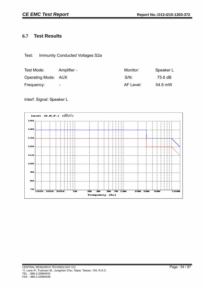
6.7 Test Results
Test: Immunity Conducted Voltages S2a
Test Mode: Amplifier - Monitor: Speaker L
Operating Mode: AUX S/N: 75.6 dB
Frequency: - AF Level: 54.6 mW
Interf. Signal: Speaker L

CE EMC Test Report Report No.:O13-I210-1303-372
CENTRAL RESEARCH TECHNOLOGY CO. Page : 55 / 97 11, Lane 41, Fushuen St., Jungshan Chiu, Taipei, Taiwan, 104, R.O.C. TEL. : 886-2-25984542 FAX. : 886-2-25984546
Test Mode: Amplifier - Monitor: Speaker L
Operating Mode: AUX S/N: 75.6 dB
Frequency: - AF Level: 54.6 mW
Interf. Signal: Speaker R

CE EMC Test Report Report No.:O13-I210-1303-372
CENTRAL RESEARCH TECHNOLOGY CO. Page : 56 / 97 11, Lane 41, Fushuen St., Jungshan Chiu, Taipei, Taiwan, 104, R.O.C. TEL. : 886-2-25984542 FAX. : 886-2-25984546
Test: Immunity Conducted Voltages S2a
Test Mode: Amplifier - Monitor: Speaker L
Operating Mode: AUX S/N: 75.6 dB
Frequency: - AF Level: 54.6 mW
Interf. Signal: Mains

CE EMC Test Report Report No.:O13-I210-1303-372
CENTRAL RESEARCH TECHNOLOGY CO. Page : 57 / 97 11, Lane 41, Fushuen St., Jungshan Chiu, Taipei, Taiwan, 104, R.O.C. TEL. : 886-2-25984542 FAX. : 886-2-25984546
Test Mode: Amplifier - Monitor: Speaker L
Operating Mode: AUX S/N: 75.6 dB
Frequency: - AF Level: 54.6 mW
Interf. Signal: Source1 L

CE EMC Test Report Report No.:O13-I210-1303-372
CENTRAL RESEARCH TECHNOLOGY CO. Page : 58 / 97 11, Lane 41, Fushuen St., Jungshan Chiu, Taipei, Taiwan, 104, R.O.C. TEL. : 886-2-25984542 FAX. : 886-2-25984546
Test: Immunity Conducted Voltages S2a
Test Mode: Amplifier - Monitor: Speaker L
Operating Mode: AUX S/N: 75.6 dB
Frequency: - AF Level: 54.6 mW
Interf. Signal: Source1 R

CE EMC Test Report Report No.:O13-I210-1303-372
CENTRAL RESEARCH TECHNOLOGY CO. Page : 59 / 97 11, Lane 41, Fushuen St., Jungshan Chiu, Taipei, Taiwan, 104, R.O.C. TEL. : 886-2-25984542 FAX. : 886-2-25984546
Test Mode: Amplifier - Monitor: Speaker L
Operating Mode: AUX S/N: 75.6 dB
Frequency: - AF Level: 54.6 mW
Interf. Signal: Preouts1 L

CE EMC Test Report Report No.:O13-I210-1303-372
CENTRAL RESEARCH TECHNOLOGY CO. Page : 60 / 97 11, Lane 41, Fushuen St., Jungshan Chiu, Taipei, Taiwan, 104, R.O.C. TEL. : 886-2-25984542 FAX. : 886-2-25984546
Test: Immunity Conducted Voltages S2a
Test Mode: Amplifier - Monitor: Speaker L
Operating Mode: AUX S/N: 75.6 dB
Frequency: - AF Level: 54.6 mW
Interf. Signal: Preouts1 R

CE EMC Test Report Report No.:O13-I210-1303-372
CENTRAL RESEARCH TECHNOLOGY CO. Page : 61 / 97 11, Lane 41, Fushuen St., Jungshan Chiu, Taipei, Taiwan, 104, R.O.C. TEL. : 886-2-25984542 FAX. : 886-2-25984546
Test: Immunity Conducted Voltages S2a
Test Mode: Amplifier - Monitor: Speaker R
Operating Mode: AUX S/N: 75.8 dB
Frequency: - AF Level: 58.3 mW
Interf. Signal: Speaker L

CE EMC Test Report Report No.:O13-I210-1303-372
CENTRAL RESEARCH TECHNOLOGY CO. Page : 62 / 97 11, Lane 41, Fushuen St., Jungshan Chiu, Taipei, Taiwan, 104, R.O.C. TEL. : 886-2-25984542 FAX. : 886-2-25984546
Test Mode: Amplifier - Monitor: Speaker R
Operating Mode: AUX S/N: 75.8 dB
Frequency: - AF Level: 58.3 mW
Interf. Signal: Speaker R

CE EMC Test Report Report No.:O13-I210-1303-372
CENTRAL RESEARCH TECHNOLOGY CO. Page : 63 / 97 11, Lane 41, Fushuen St., Jungshan Chiu, Taipei, Taiwan, 104, R.O.C. TEL. : 886-2-25984542 FAX. : 886-2-25984546
Test: Immunity Conducted Voltages S2a
Test Mode: Amplifier - Monitor: Speaker R
Operating Mode: AUX S/N: 75.8 dB
Frequency: - AF Level: 58.3 mW
Interf. Signal: Mains

CE EMC Test Report Report No.:O13-I210-1303-372
CENTRAL RESEARCH TECHNOLOGY CO. Page : 64 / 97 11, Lane 41, Fushuen St., Jungshan Chiu, Taipei, Taiwan, 104, R.O.C. TEL. : 886-2-25984542 FAX. : 886-2-25984546
Test Mode: Amplifier - Monitor: Speaker R
Operating Mode: AUX S/N: 75.8 dB
Frequency: - AF Level: 58.3 mW
Interf. Signal: Source1 L

CE EMC Test Report Report No.:O13-I210-1303-372
CENTRAL RESEARCH TECHNOLOGY CO. Page : 65 / 97 11, Lane 41, Fushuen St., Jungshan Chiu, Taipei, Taiwan, 104, R.O.C. TEL. : 886-2-25984542 FAX. : 886-2-25984546
Test: Immunity Conducted Voltages S2a
Test Mode: Amplifier - Monitor: Speaker R
Operating Mode: AUX S/N: 75.8 dB
Frequency: - AF Level: 58.3 mW
Interf. Signal: Source1 R

CE EMC Test Report Report No.:O13-I210-1303-372
CENTRAL RESEARCH TECHNOLOGY CO. Page : 66 / 97 11, Lane 41, Fushuen St., Jungshan Chiu, Taipei, Taiwan, 104, R.O.C. TEL. : 886-2-25984542 FAX. : 886-2-25984546
Test Mode: Amplifier - Monitor: Speaker R
Operating Mode: AUX S/N: 75.8 dB
Frequency: - AF Level: 58.3 mW
Interf. Signal: Preouts1 L

CE EMC Test Report Report No.:O13-I210-1303-372
CENTRAL RESEARCH TECHNOLOGY CO. Page : 67 / 97 11, Lane 41, Fushuen St., Jungshan Chiu, Taipei, Taiwan, 104, R.O.C. TEL. : 886-2-25984542 FAX. : 886-2-25984546
Test: Immunity Conducted Voltages S2a
Test Mode: Amplifier - Monitor: Speaker R
Operating Mode: AUX S/N: 75.8 dB
Frequency: - AF Level: 58.3 mW
Interf. Signal: Preouts1 R
CE EMC Test Report Report No.:O13-I210-1303-372
CENTRAL RESEARCH TECHNOLOGY CO. Page : 68 / 97 11, Lane 41, Fushuen St., Jungshan Chiu, Taipei, Taiwan, 104, R.O.C. TEL. : 886-2-25984542 FAX. : 886-2-25984546
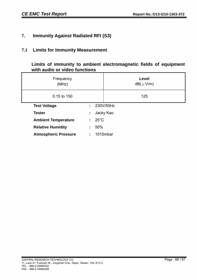
7. Immunity Against Radiated RFI (S3)
7.1 Limits for Immunity Measurement
Limits of immunity to ambient electromagnetic fields of equipment with audio or video functions
Frequency (MHz)
Level dB(μV/m)
0.15 to 150 125
Test Voltage : 230V/50Hz
Tester : Jacky Kao
Ambient Temperature : 25°C
Relative Humidity : 50%
Atmospheric Pressure : 1015mbar
CE EMC Test Report Report No.:O13-I210-1303-372
CENTRAL RESEARCH TECHNOLOGY CO. Page : 69 / 97 11, Lane 41, Fushuen St., Jungshan Chiu, Taipei, Taiwan, 104, R.O.C. TEL. : 886-2-25984542 FAX. : 886-2-25984546
7.2 Description of Performance Criteria
Performance criterion A
The equipment shall continue to operate as intended during the test. No change of actual operating state (for example change of channel) is allowed as a result of the application of the test. Multifunction equipment shall for each function meet the relevant requirements. Evaluation is carried out for audio and video functions. The equipment is supposed to operate as intended if the criteria of “Evaluation of audio quality” and/or “Evaluation of picture quality” are fulfilled.
Performance criterion B
The equipment shall continue to operate as intended after the test. No loss of function is allowed after the test when the apparatus is used as intended, but failures which are recovered automatically but which cause temporary delay in processing, are permissible. No change of actual operating state for example change of channel or stored data and settings is allowed as a result of the application of the test. During the test, degradation of performance is allowed.

CE EMC Test Report Report No.:O13-I210-1303-372
CENTRAL RESEARCH TECHNOLOGY CO. Page : 70 / 97 11, Lane 41, Fushuen St., Jungshan Chiu, Taipei, Taiwan, 104, R.O.C. TEL. : 886-2-25984542 FAX. : 886-2-25984546
7.3 Test Instruments
Test Site and Equipment
Manufacturer Model No./ Serial No.
Last Calibration Date
Calibration Due Date
Test Receiver R&S ESCI/
100316 March 1, 2013 March 1, 2014
Signal Generator R&S SML01/ 104230
Dec. 15, 2011 Dec. 15, 2013
Signal Generator R&S SML02/ 101519
Dec. 15, 2011 Dec. 15, 2013
Audio Analyzer R&S UPL/
101285 Dec. 16, 2011 Dec. 16, 2013
Power Amplifier R&S BSA 1515-25/
055966-5 Dec. 16, 2011 Dec. 16, 2013
TV Test Transmitter
R&S SFQ/
100565 Dec. 14, 2011 Dec. 14, 2013
TV Test Transmitter
R&S SFM/
100182 Dec. 14, 2011 Dec. 14, 2013
TV Generator SECAM
R&S SGSF/ 100062
Dec. 19, 2011 Dec. 19, 2013
TV Generator NTSC
R&S SGMF/ 100043
Dec. 19, 2011 Dec. 19, 2013
TV Generator PAL
R&S SGPF/ 100160
Dec. 19, 2011 Dec. 19, 2013
MPEG2 Measurement
Generator R&S
DVG/ 100403
Dec. 19, 2011 Dec. 19, 2013
Power Meter R&S NRVD/
837333/066 Dec. 3, 2012 Dec. 3, 2013
RF Probe R&S URV5-Z4/ 100121
Oct. 18, 2012 Oct. 18, 2013
Test Software R&S T80-K1 V2.1 NCR NCR
TR20 shielded room
ETS LINDGREN
TR20/ 17873-2
NCR NCR
Note:
1. The calibrations are traceable to NML/ROC.
2. NCR : No Calibration Required.

CE EMC Test Report Report No.:O13-I210-1303-372
CENTRAL RESEARCH TECHNOLOGY CO. Page : 71 / 97 11, Lane 41, Fushuen St., Jungshan Chiu, Taipei, Taiwan, 104, R.O.C. TEL. : 886-2-25984542 FAX. : 886-2-25984546
7.4 Test Procedures
a. The EUT is placed on a non-metallic support, 0.1m high, in the center of the stripline.
b. The wanted signal is fed to all input terminals respectively. The unwanted signal is fed to a matching network of the stripline.
c. The ground connection of the mains filter(M) is directly connected to the JACKY.
d. All unused input/output connections on the EUT are terminated and shielded with the proper resistance.
e. The power supply to the mains of the EUT is attached to the mains filter(M).
f. The measurements were performed with test software T80-K1 Ver. 2.1.

CE EMC Test Report Report No.:O13-I210-1303-372
CENTRAL RESEARCH TECHNOLOGY CO. Page : 72 / 97 11, Lane 41, Fushuen St., Jungshan Chiu, Taipei, Taiwan, 104, R.O.C. TEL. : 886-2-25984542 FAX. : 886-2-25984546
7.5 Test Configurations
7.6 Photographs of the Test Configurations
Please refer to the Attachment 1 of the present report.
System Panel
Isolation Transformer
AC Power Source
Test System TS9980 50/150 Ω
Desired Signal
Analyzer In
Interfering Signal
Desired + Interfering Signal
Ri
100 Ω
1 kΩ
2.2 KΩ
Audio System
Left
Right
Left
Right
Speaker
AF Generator
AC Power
EUT
Antenna Input
Headphones
Left
Right
Left
Right AF Out
AF In Right
AC Power Source
M
Left
BP
W10.08
W10.07
W10.09 BS 8 Ω
150 Ω Att
JACKY
50/150 Ω
BS 300 Ω
BS Infinity

CE EMC Test Report Report No.:O13-I210-1303-372
CENTRAL RESEARCH TECHNOLOGY CO. Page : 73 / 97 11, Lane 41, Fushuen St., Jungshan Chiu, Taipei, Taiwan, 104, R.O.C. TEL. : 886-2-25984542 FAX. : 886-2-25984546
7.7 Test Results
Test: Immunity Radiated Fields S3
Test Mode: Amplifier - Monitor: Speaker L
Operating Mode: AUX S/N: 75.3 dB
Frequency: - AF Level: 59.9 mW
Interf. Signal: Scan, K2 = 1.6 dB
CE EMC Test Report Report No.:O13-I210-1303-372
CENTRAL RESEARCH TECHNOLOGY CO. Page : 74 / 97 11, Lane 41, Fushuen St., Jungshan Chiu, Taipei, Taiwan, 104, R.O.C. TEL. : 886-2-25984542 FAX. : 886-2-25984546
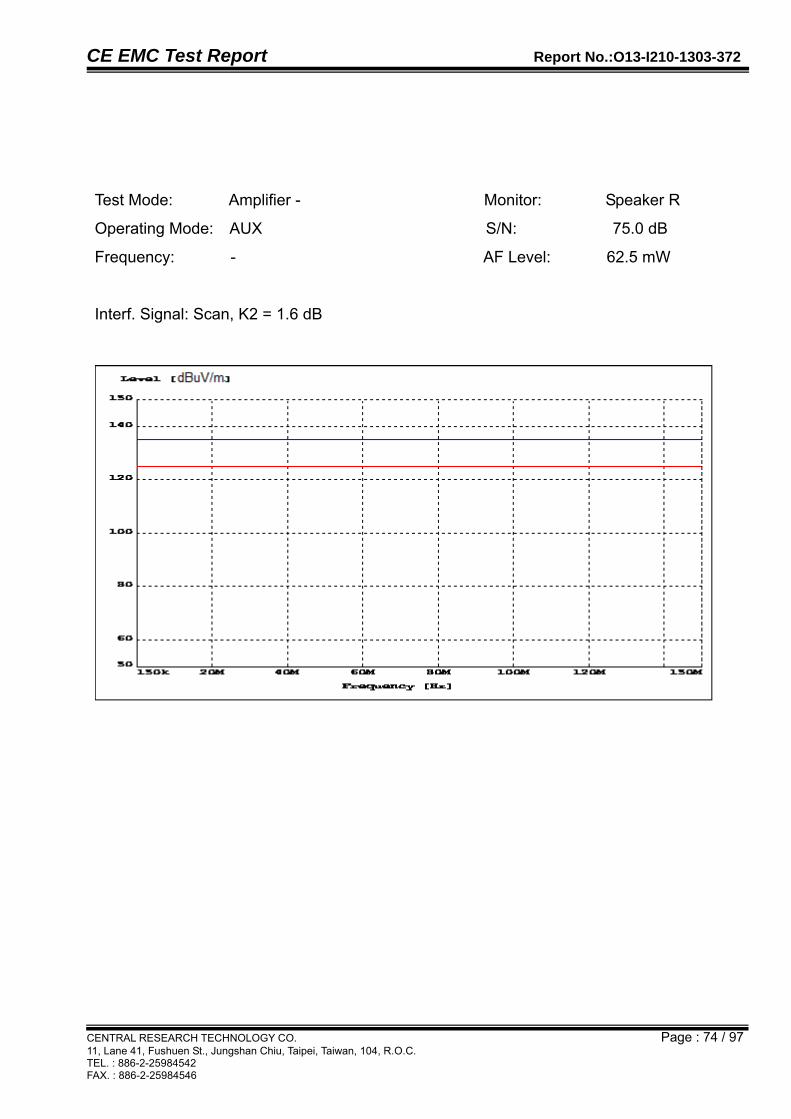
Test Mode: Amplifier - Monitor: Speaker R
Operating Mode: AUX S/N: 75.0 dB
Frequency: - AF Level: 62.5 mW
Interf. Signal: Scan, K2 = 1.6 dB
CE EMC Test Report Report No.:O13-I210-1303-372
CENTRAL RESEARCH TECHNOLOGY CO. Page : 75 / 97 11, Lane 41, Fushuen St., Jungshan Chiu, Taipei, Taiwan, 104, R.O.C. TEL. : 886-2-25984542 FAX. : 886-2-25984546
8. Keyed Carrier(S5)
Test Result : PASS
8.1 Limits for Immunity Measurement
Frequency
(MHz)
Level
dB(V)/m
900 130
Test Voltage : 230V/50Hz
Tester : Jacky Kao
Ambient Temperature : 26°C
Relative Humidity : 52%
Atmospheric Pressure : 1016mbar

CE EMC Test Report Report No.:O13-I210-1303-372
CENTRAL RESEARCH TECHNOLOGY CO. Page : 76 / 97 11, Lane 41, Fushuen St., Jungshan Chiu, Taipei, Taiwan, 104, R.O.C. TEL. : 886-2-25984542 FAX. : 886-2-25984546
8.2 Description of Performance Criteria
Performance criterion A
The equipment shall continue to operate as intended during the test. No change of actual operating state (for example change of channel) is allowed as a result of the application of the test. Multifunction equipment shall for each function meet the relevant requirements. Evaluation is carried out for audio and video functions. The equipment is supposed to operate as intended if the criteria of “Evaluation of audio quality” and/or “Evaluation of picture quality” are fulfilled.
Performance criterion B The equipment shall continue to operate as intended after the test. No loss of function is allowed after the test when the apparatus is used as intended, but failures which are recovered automatically but which cause temporary delay in processing, are permissible. No change of actual operating state for example change of channel or stored data and settings is allowed as a result of the application of the test. During the test, degradation of performance is allowed.
CE EMC Test Report Report No.:O13-I210-1303-372
CENTRAL RESEARCH TECHNOLOGY CO. Page : 77 / 97 11, Lane 41, Fushuen St., Jungshan Chiu, Taipei, Taiwan, 104, R.O.C. TEL. : 886-2-25984542 FAX. : 886-2-25984546
8.3 Test Instruments
Test Site and Equipment
Manufacturer Model No./ Serial No.
Last Calibration Date
Calibration Due Date
Signal Generator R&S SML01/ 104230
Dec. 15, 2011 Dec. 15, 2013
Signal Generator R&S SML02/ 101519
Dec. 15, 2011 Dec. 15, 2013
Audio Analyzer R&S UPL/
101285 Dec. 16, 2011 Dec. 16, 2013
TV Test Transmitter
R&S SFQ/
100565 Dec. 14, 2011 Dec. 14, 2013
TV Test Transmitter
R&S SFM/
100182 Dec. 14, 2011 Dec. 14, 2013
TV Generator SECAM
R&S SGSF/ 100062
Dec. 19, 2011 Dec. 19, 2013
TV Generator NTSC
R&S SGMF/ 100043
Dec. 19, 2011 Dec. 19, 2013
TV Generator PAL
R&S SGPF/ 100160
Dec. 19, 2011 Dec. 19, 2013
MPEG2 Measurement
Generator R&S
DVG/ 100403
Dec. 19, 2011 Dec. 19, 2013
50/75 Ohm Matching Pad
MINI-CIRCUITSUNMD-5075/
3 0605 March 4, 2013 March 4, 2014
Power Meter R&S NRVD/
837333/066 Dec. 3, 2012 Dec. 3, 2013
RF Probe R&S URV5-Z4/ 100121
Oct. 18, 2012 Oct. 18, 2013
Dual Directional Coupler
AR DC6180/
28730 Jan. 3, 2013 Jan. 3, 2014
Power Amplifier
AR 150W1000/
29167 NCR NCR
Bi-Log Antenna EMCO 3142B/ 1716
NCR NCR
Isotropic E Field Probe
AR FL7006/ 0336500
April 12, 2013 April 12, 2014
Dual Channel Power Meter
R&S NRVD/ 100499
Jan. 4, 2013 Jan. 4, 2014

CE EMC Test Report Report No.:O13-I210-1303-372
CENTRAL RESEARCH TECHNOLOGY CO. Page : 78 / 97 11, Lane 41, Fushuen St., Jungshan Chiu, Taipei, Taiwan, 104, R.O.C. TEL. : 886-2-25984542 FAX. : 886-2-25984546
Test Site and Equipment
Manufacturer Model No./ Serial No.
Last Calibration Date
Calibration Due Date
Test Software R&S T80-K1/ Ver. 2.1
NCR NCR
TR2 fully-
anechoic chamber ETS.
LINDGREN TR2/
15353-R Sept. 16, 2012 Sept. 16, 2013
Note:
1. The calibrations are traceable to NML/ROC.
2. NCR : No Calibration Required.
3. The calibration date of the fully-anechoic chamber listed above is the date of Field Uniformity Calibration measurement.

CE EMC Test Report Report No.:O13-I210-1303-372
CENTRAL RESEARCH TECHNOLOGY CO. Page : 79 / 97 11, Lane 41, Fushuen St., Jungshan Chiu, Taipei, Taiwan, 104, R.O.C. TEL. : 886-2-25984542 FAX. : 886-2-25984546
8.4 Test Procedures
a. The EUT was set up per the test configuration figured in the next section of this chapter to simulate the typical usage per the user’s manual.
b. If the EUT is tabletop equipment, it was placed on a wooden table with a height of 0.8 meters and 3 meters away from the transmitting antenna in the fully anechoic chamber.
c. If the EUT is floor-standing equipment, it was placed on a non-conducted support with a height of 0.1 meters and 3 meters away from the transmitting antenna in the fully anechoic chamber. Also if the floor-standing equipment which is capable of being stood on a non-conducting 0.8m high platform may be so arranged.
d. All EUT’s individual faces shall be fully enclosed by the “uniform area” and its wires shall be arranged parallel to the uniform area of the field.
e. Before testing the EUT, the intensity of the established field strength is checked by placing the field sensor at a calibration grid point to give the calibrated field strength to measure the EUT.
f. After the calibration has been verified, the test field can be generated using the values obtained from the calibration.
g. Perform the test with the specified immunity level in the test frequency range and with the specified modulation type.
h. The transmitting antenna is normally facing the front side of the EUT with vertical polarization to perform the test.
i. The dwell time shall be not less than the time necessary for the EUT to be exercised and be able to respond.
j. Record the performance of the EUT.

CE EMC Test Report Report No.:O13-I210-1303-372
CENTRAL RESEARCH TECHNOLOGY CO. Page : 80 / 97 11, Lane 41, Fushuen St., Jungshan Chiu, Taipei, Taiwan, 104, R.O.C. TEL. : 886-2-25984542 FAX. : 886-2-25984546
8.5 Test Setup
8.6 Photographs of the Test Configurations
Please refer to the Attachment 1 of the present report.
System Panel
BS 8 Ω
BS 300Ω
Isolation Transformer
Test System TS9980 Anecholc Chamber
BS Infinity
Desired Signal
Analyzer In
Interfering Signal
Desired + Interfering Signal
Audio System Left
Right
Left
Right
Speaker
AF Generator
AC Power
AC Power Source
EUT
Antenna Input
Headphones
Right
Left
Left
Right
AF Out
AF In
Left
Right
Antenna
AC Power Source
Ri
100 Ω
1 kΩ
2.2 KΩ
50/75 Ω
Insertion Unit URV5-Z4
Power Meter
M

CE EMC Test Report Report No.:O13-I210-1303-372
CENTRAL RESEARCH TECHNOLOGY CO. Page : 81 / 97 11, Lane 41, Fushuen St., Jungshan Chiu, Taipei, Taiwan, 104, R.O.C. TEL. : 886-2-25984542 FAX. : 886-2-25984546
8.7 Test Results
Test: Keyed Carrier S5
Test Mode: Amplifier - Monitor: Speaker L
Operating Mode: AUX S/N: 57.5 dB
Frequency: - AF Level: 63.2 mW
Interf. Signal: Scan

CE EMC Test Report Report No.:O13-I210-1303-372
CENTRAL RESEARCH TECHNOLOGY CO. Page : 82 / 97 11, Lane 41, Fushuen St., Jungshan Chiu, Taipei, Taiwan, 104, R.O.C. TEL. : 886-2-25984542 FAX. : 886-2-25984546
Test Mode: Amplifier - Monitor: Speaker R
Operating Mode: AUX S/N: 57.0 dB
Frequency: - AF Level: 66.7 mW
Interf. Signal: Scan

CE EMC Test Report Report No.:O13-I210-1303-372
CENTRAL RESEARCH TECHNOLOGY CO. Page : 83 / 97 11, Lane 41, Fushuen St., Jungshan Chiu, Taipei, Taiwan, 104, R.O.C. TEL. : 886-2-25984542 FAX. : 886-2-25984546
9. Electrostatic Discharge (ESD) Immunity Test
9.1 Specifications of Immunity Test Requirement
Product (Generic) Standard : EN 55020:2007+A11:2011
Basic Standard : IEC 61000-4-2:2008
Required Performance : B
Test Level : 2 (Contact discharge)
: 3 (Air discharge)
Discharge Voltage : Contact ±4kV (Direct / Indirect discharge)
: Air ±2 kV, ±4kV, ±8kV (Direct discharge)
Time Interval : 1 sec. minimum
Number of discharges : Minimum 20 times at each test point
Test Voltage : 230V/50Hz
Tester : Rick
Ambient Temperature : 22°C
Relative Humidity : 48%
Atmospheric Pressure : 1012mbar

CE EMC Test Report Report No.:O13-I210-1303-372
CENTRAL RESEARCH TECHNOLOGY CO. Page : 84 / 97 11, Lane 41, Fushuen St., Jungshan Chiu, Taipei, Taiwan, 104, R.O.C. TEL. : 886-2-25984542 FAX. : 886-2-25984546
9.2 Description of Performance Criteria
Performance criterion A
The equipment shall continue to operate as intended during the test. No change of actual operating state (for example change of channel) is allowed as a result of the application of the test. Multifunction equipment shall for each function meet the relevant requirements. Evaluation is carried out for audio and video functions. The equipment is supposed to operate as intended if the criteria of “Evaluation of audio quality” and/or “Evaluation of picture quality” are fulfilled.
Performance criterion B The equipment shall continue to operate as intended after the test. No loss of function is allowed after the test when the apparatus is used as intended, but failures which are recovered automatically but which cause temporary delay in processing, are permissible. No change of actual operating state for example change of channel or stored data and settings is allowed as a result of the application of the test. During the test, degradation of performance is allowed.

CE EMC Test Report Report No.:O13-I210-1303-372
CENTRAL RESEARCH TECHNOLOGY CO. Page : 85 / 97 11, Lane 41, Fushuen St., Jungshan Chiu, Taipei, Taiwan, 104, R.O.C. TEL. : 886-2-25984542 FAX. : 886-2-25984546
9.3 Test Instruments
Test Site and Equipment
Manufacturer Model No./ Serial No.
Last Calibration Date
Calibration Due Date
Electrostatic Generator EM TEST
DITO/ V0537100716
July 5, 2012 July 5, 2013
TR8 shielded room
ETS. LINDGREN
TR8/ 15353-C
NCR NCR
Note:
1. The calibrations are traceable to NML/ROC.
2. NCR : No Calibration Required.
CE EMC Test Report Report No.:O13-I210-1303-372
CENTRAL RESEARCH TECHNOLOGY CO. Page : 86 / 97 11, Lane 41, Fushuen St., Jungshan Chiu, Taipei, Taiwan, 104, R.O.C. TEL. : 886-2-25984542 FAX. : 886-2-25984546
9.4 Test Procedures
a. The EUT was set up per the test configuration figured in the next section of this chapter to simulate the typical usage per the user’s manual.
b. If the EUT is tabletop equipment, it was placed on a wooden table with a height of 0.8 meters above the ground reference plane in the shielded room. Also a HCP (Horizontal Coupling Plane) which was connected to the ground reference plane
via a cable with a 470k resister located at each end was placed on the wooden table and isolated with the EUT by an insulating support 0.5mm thick. The ground reference plane shall project beyond the EUT or HCP by at least 0.5m on all sides.
c. If the EUT is floor-standing equipment, it was placed on a non-conducted support with a height of 0.1 meters above the ground reference plane in the shielded room. The ground reference plane shall project beyond the EUT by at least 0.5m on all sides.
d. Keep the EUT 1m away from all other metallic walls in the shielded room as the minimum distance.
e. The static electricity discharges shall be applied only to those points and surfaces of the EUT which are accessible to persons during normal use. Contact discharge is the preferred test method and it is applied to the conductive surfaces of EUT and coupling planes. Air discharge shall be used where contact discharge cannot be performed and it is applied to the insulating surfaces of EUT.
f. The discharge return cable of the generator shall be kept at a distance of at least 0.2m from the EUT whilst the discharge is being applied.
g. The time interval between successive single discharges was at least 1 second.
h. Select appropriate points of the EUT for contact discharge and put marks on it to indicate the tested point(s). Then start the contact discharge with the tip of the discharge electrode to touch the EUT before the discharge switch is operated.
i. Use the round discharge tip of the discharge electrode to scan the EUT to select the points for air discharge. Then start the air discharge by approaching the discharge electrode as fast as possible to touch the EUT. After each discharge, the ESD generator shall be removed from the EUT.
j. The indirect HCP discharge test is applied at the front edge of each HCP opposite the center point of each unit of the EUT and 0.1m from the front of the EUT. The long axis of the discharge electrode shall be in the plane of the HCP and perpendicular to its front edge during the discharge.

CE EMC Test Report Report No.:O13-I210-1303-372
CENTRAL RESEARCH TECHNOLOGY CO. Page : 87 / 97 11, Lane 41, Fushuen St., Jungshan Chiu, Taipei, Taiwan, 104, R.O.C. TEL. : 886-2-25984542 FAX. : 886-2-25984546
k. The indirect VCP (Vertical Coupling Plane) discharge test is applied to the center
of one vertical edge of the coupling plane. The VCP, of dimensions 0.5m0.5m, is placed parallel to, and positioned at a distance of 0.1m from the EUT. It shall be applied with sufficient different positions such that the four faces of the EUT are completely illuminated.

CE EMC Test Report Report No.:O13-I210-1303-372
CENTRAL RESEARCH TECHNOLOGY CO. Page : 88 / 97 11, Lane 41, Fushuen St., Jungshan Chiu, Taipei, Taiwan, 104, R.O.C. TEL. : 886-2-25984542 FAX. : 886-2-25984546
9.5 Test Configurations
9.6 Photographs of the Test Configurations
Please refer to the Attachment 1 of the present report.

CE EMC Test Report Report No.:O13-I210-1303-372
CENTRAL RESEARCH TECHNOLOGY CO. Page : 89 / 97 11, Lane 41, Fushuen St., Jungshan Chiu, Taipei, Taiwan, 104, R.O.C. TEL. : 886-2-25984542 FAX. : 886-2-25984546
9.7 Test Results
Test Mode : Normal
Performance Discharge Voltage
(kV)
Type of discharge
Label for Dischargeable
Points Required Observation
Result (Pass/Fail)
4 Contact 9~13 B B(2) Pass
2 Air 1~8 B A(1) Pass
+4 Air 1,3~8 B A(1) Pass
-4 Air 2 B B(2) Pass
8 Air 1~8 B A(1) Pass
4 HCP-Bottom Edge of the HCP B B(2) Pass
4 VCP-Front Center of the VCP B B(2) Pass
4 VCP-Left Center of the VCP B B(2) Pass
4 VCP-Back Center of the VCP B B(2) Pass
4 VCP-Right Center of the VCP B B(2) Pass
Observation of Performance during Test
(1) Normal operation condition specified by manufacturer during the test.
(2) The noise would appear from speaker while test is performing, it could self-recover after finishing the test.

CE EMC Test Report Report No.:O13-I210-1303-372
CENTRAL RESEARCH TECHNOLOGY CO. Page : 90 / 97 11, Lane 41, Fushuen St., Jungshan Chiu, Taipei, Taiwan, 104, R.O.C. TEL. : 886-2-25984542 FAX. : 886-2-25984546
Photographs of the Test Points on the EUT for ESD Test

CE EMC Test Report Report No.:O13-I210-1303-372
CENTRAL RESEARCH TECHNOLOGY CO. Page : 91 / 97 11, Lane 41, Fushuen St., Jungshan Chiu, Taipei, Taiwan, 104, R.O.C. TEL. : 886-2-25984542 FAX. : 886-2-25984546

CE EMC Test Report Report No.:O13-I210-1303-372
CENTRAL RESEARCH TECHNOLOGY CO. Page : 92 / 97 11, Lane 41, Fushuen St., Jungshan Chiu, Taipei, Taiwan, 104, R.O.C. TEL. : 886-2-25984542 FAX. : 886-2-25984546
10. Electrical fast transient / burst (EFT) Immunity Test
10.1 Specifications of Immunity Test Requirement
Product (Generic) Standard : EN 55020:2007+A11:2011
Basic Standard : IEC 61000-4-4:2004+A1:2010
Required Performance : B
Test Level : 2
Voltage Peak : ±1kV (on power supply port)
Impulse Frequency : 5kHz
Wave Shape of the Pulse (Tr/Th) : 5ns / 50ns
Burst Duration : 15ms
Burst Period : 300ms
Time Duration : 1 min
Test Voltage : 230V/50Hz
Tester : Wilson
Ambient Temperature : 24°C
Relative Humidity : 63%
Atmospheric Pressure : 1008mbar

CE EMC Test Report Report No.:O13-I210-1303-372
CENTRAL RESEARCH TECHNOLOGY CO. Page : 93 / 97 11, Lane 41, Fushuen St., Jungshan Chiu, Taipei, Taiwan, 104, R.O.C. TEL. : 886-2-25984542 FAX. : 886-2-25984546
10.2 Description of Performance Criteria
Performance criterion A
The equipment shall continue to operate as intended during the test. No change of actual operating state (for example change of channel) is allowed as a result of the application of the test. Multifunction equipment shall for each function meet the relevant requirements. Evaluation is carried out for audio and video functions. The equipment is supposed to operate as intended if the criteria of “Evaluation of audio quality” and/or “Evaluation of picture quality” are fulfilled.
Performance criterion B The equipment shall continue to operate as intended after the test. No loss of function is allowed after the test when the apparatus is used as intended, but failures which are recovered automatically but which cause temporary delay in processing, are permissible. No change of actual operating state for example change of channel or stored data and settings is allowed as a result of the application of the test. During the test, degradation of performance is allowed.

CE EMC Test Report Report No.:O13-I210-1303-372
CENTRAL RESEARCH TECHNOLOGY CO. Page : 94 / 97 11, Lane 41, Fushuen St., Jungshan Chiu, Taipei, Taiwan, 104, R.O.C. TEL. : 886-2-25984542 FAX. : 886-2-25984546
10.3 Test Instruments
Test Site and Equipment
Manufacturer Model No./ Serial No.
Last Calibration Date
Calibration Due Date
EFT/Burst Simulator
EMC PARTNERTRA2000IN6/
870 April 2, 2013 April 2, 2014
Coupling Clamp
EMC PARTNERCN-EFT1000/
532 NCR NCR
Test Software EMC PARTNERTEMA/
Ver. 1.86 NCR NCR
TR7 shielded room
ETS. LINDGREN
TR7/ 15353-D
NCR NCR
Note:
1. The calibrations are traceable to NML/ROC.
2. NCR : No Calibration Required.

CE EMC Test Report Report No.:O13-I210-1303-372
CENTRAL RESEARCH TECHNOLOGY CO. Page : 95 / 97 11, Lane 41, Fushuen St., Jungshan Chiu, Taipei, Taiwan, 104, R.O.C. TEL. : 886-2-25984542 FAX. : 886-2-25984546
10.4 Test Procedures
a. The EUT was set up per the test configuration figured in the next section of this chapter to simulate the typical usage per the user’s manual.
b. If the EUT is tabletop equipment, it was placed on a wooden table with a height of 0.8 meters above the ground reference plane in the shielded room. The ground reference plane shall project beyond the EUT by at least 0.1m on all sides.
c. If the EUT is floor-standing equipment, it was placed on a non-conducted support with a height of 0.1 meters above the ground reference plane in the shielded room. The ground reference plane shall project beyond the EUT by at least 0.1m on all sides.
d. Keep the EUT 0.5m away from all other conductive structures, except the ground reference plane beneath the EUT as the minimum distance. Also if any, the minimum distance between the coupling clamp and all other conductive structures, except the ground reference plane beneath the coupling clamp and EUT shall be 0.5m.
e. Keep the length of the power and signal lines, if required, between the coupling device and the EUT to be 1m or less. If a non-detachable supply cable more than 1m long, the excess length of this cable shall be gathered into a flat coil with a 0.4m diameter and situated at a distance of 0.1m above the ground reference plane.
f. Connect the EUT’s power source to the appropriate power through the coupling devices and perform the specified test level.
g. If any, connect all the I/O signal, data and control lines between EUT and accessories/support units through the coupling devices and perform the specified test level.
h. Record the performance of the EUT.

CE EMC Test Report Report No.:O13-I210-1303-372
CENTRAL RESEARCH TECHNOLOGY CO. Page : 96 / 97 11, Lane 41, Fushuen St., Jungshan Chiu, Taipei, Taiwan, 104, R.O.C. TEL. : 886-2-25984542 FAX. : 886-2-25984546
10.5 Test Configurations
Power supply port Test
10.6 Photographs of the Test Configurations
Please refer to the Attachment 1 of the present report.
Control PC & Monitor
EUT Included Units
EFT / Burst Generator
Reference Ground Plane
80cm
AC Power Source
10cm insulating support

CE EMC Test Report Report No.:O13-I210-1303-372
CENTRAL RESEARCH TECHNOLOGY CO. Page : 97 / 97 11, Lane 41, Fushuen St., Jungshan Chiu, Taipei, Taiwan, 104, R.O.C. TEL. : 886-2-25984542 FAX. : 886-2-25984546
10.7 Test Results
Test Mode : Normal
Performance Injected Line
Voltage Peak (kV)
Injected Method Required Observation
Result (Pass/Fail)
L1 - L2 - PE +1.0 Direct B B(1) Pass
L1 - L2 - PE -1.0 Direct B B(1) Pass
Observation of Performance during Test
(1) The noise would appear from speaker and 1kHz audio signal would disappear while test is performing, it could self-recover after finishing the test.

CE EMC Test Report Report No.:O13-I210-1303-372
CENTRAL RESEARCH TECHNOLOGY CO. Page : A1-1 11, Lane 41, Fushuen St., Jungshan Chiu, Taipei, Taiwan, 104, R.O.C. TEL. : 886-2-25984542 FAX. : 886-2-25984546
Attachment 1
Photographs of the Test Configurations

CE EMC Test Report Report No.:O13-I210-1303-372
CENTRAL RESEARCH TECHNOLOGY CO. Page : A1-i 11, Lane 41, Fushuen St., Jungshan Chiu, Taipei, Taiwan, 104, R.O.C. TEL. : 886-2-25984542 FAX. : 886-2-25984546
Contents
1. Conducted Emission Measurement.......................................................... 1
2. Disturbance Power Measurement ............................................................. 2
3. Harmonic Current & Voltage Fluctuations Emission Measurement....... 7
4. Immunity Against RFI Voltage (S2a) ......................................................... 8
5. Immunity Against Radiated RFI (S3) ......................................................... 9
6. Keyed Carrier (S5) .................................................................................... 10
7. Electrostatic Discharge (ESD) Immunity Test .........................................11
8. Electrical fast transient / burst (EFT) Immunity Test ..............................11

CE EMC Test Report Report No.:O13-I210-1303-372
CENTRAL RESEARCH TECHNOLOGY CO. Page : A1-1 11, Lane 41, Fushuen St., Jungshan Chiu, Taipei, Taiwan, 104, R.O.C. TEL. : 886-2-25984542 FAX. : 886-2-25984546
1. Conducted Emission Measurement

CE EMC Test Report Report No.:O13-I210-1303-372
CENTRAL RESEARCH TECHNOLOGY CO. Page : A1-2 11, Lane 41, Fushuen St., Jungshan Chiu, Taipei, Taiwan, 104, R.O.C. TEL. : 886-2-25984542 FAX. : 886-2-25984546
2. Disturbance Power Measurement

CE EMC Test Report Report No.:O13-I210-1303-372
CENTRAL RESEARCH TECHNOLOGY CO. Page : A1-3 11, Lane 41, Fushuen St., Jungshan Chiu, Taipei, Taiwan, 104, R.O.C. TEL. : 886-2-25984542 FAX. : 886-2-25984546

CE EMC Test Report Report No.:O13-I210-1303-372
CENTRAL RESEARCH TECHNOLOGY CO. Page : A1-4 11, Lane 41, Fushuen St., Jungshan Chiu, Taipei, Taiwan, 104, R.O.C. TEL. : 886-2-25984542 FAX. : 886-2-25984546

CE EMC Test Report Report No.:O13-I210-1303-372
CENTRAL RESEARCH TECHNOLOGY CO. Page : A1-5 11, Lane 41, Fushuen St., Jungshan Chiu, Taipei, Taiwan, 104, R.O.C. TEL. : 886-2-25984542 FAX. : 886-2-25984546

CE EMC Test Report Report No.:O13-I210-1303-372
CENTRAL RESEARCH TECHNOLOGY CO. Page : A1-6 11, Lane 41, Fushuen St., Jungshan Chiu, Taipei, Taiwan, 104, R.O.C. TEL. : 886-2-25984542 FAX. : 886-2-25984546

CE EMC Test Report Report No.:O13-I210-1303-372
CENTRAL RESEARCH TECHNOLOGY CO. Page : A1-7 11, Lane 41, Fushuen St., Jungshan Chiu, Taipei, Taiwan, 104, R.O.C. TEL. : 886-2-25984542 FAX. : 886-2-25984546
3. Harmonic Current & Voltage Fluctuations Emission Measurement

CE EMC Test Report Report No.:O13-I210-1303-372
CENTRAL RESEARCH TECHNOLOGY CO. Page : A1-8 11, Lane 41, Fushuen St., Jungshan Chiu, Taipei, Taiwan, 104, R.O.C. TEL. : 886-2-25984542 FAX. : 886-2-25984546
4. Immunity Against RFI Voltage (S2a)

CE EMC Test Report Report No.:O13-I210-1303-372
CENTRAL RESEARCH TECHNOLOGY CO. Page : A1-9 11, Lane 41, Fushuen St., Jungshan Chiu, Taipei, Taiwan, 104, R.O.C. TEL. : 886-2-25984542 FAX. : 886-2-25984546
5. Immunity Against Radiated RFI (S3)

CE EMC Test Report Report No.:O13-I210-1303-372
CENTRAL RESEARCH TECHNOLOGY CO. Page : A1-10 11, Lane 41, Fushuen St., Jungshan Chiu, Taipei, Taiwan, 104, R.O.C. TEL. : 886-2-25984542 FAX. : 886-2-25984546
6. Keyed Carrier (S5)

CE EMC Test Report Report No.:O13-I210-1303-372
CENTRAL RESEARCH TECHNOLOGY CO. Page : A1-11 11, Lane 41, Fushuen St., Jungshan Chiu, Taipei, Taiwan, 104, R.O.C. TEL. : 886-2-25984542 FAX. : 886-2-25984546
7. Electrostatic Discharge (ESD) Immunity Test
8. Electrical fast transient / burst (EFT) Immunity Test

CE EMC Test Report Report No.:O13-I210-1303-372
CENTRAL RESEARCH TECHNOLOGY CO. Page : A2-1 11, Lane 41, Fushuen St., Jungshan Chiu, Taipei, Taiwan, 104, R.O.C. TEL. : 886-2-25984542 FAX. : 886-2-25984546
Attachment 2
Photographs of EUT

CE EMC Test Report Report No.:O13-I210-1303-372
CENTRAL RESEARCH TECHNOLOGY CO. Page : A2-1 11, Lane 41, Fushuen St., Jungshan Chiu, Taipei, Taiwan, 104, R.O.C. TEL. : 886-2-25984542 FAX. : 886-2-25984546

CE EMC Test Report Report No.:O13-I210-1303-372
CENTRAL RESEARCH TECHNOLOGY CO. Page : A2-2 11, Lane 41, Fushuen St., Jungshan Chiu, Taipei, Taiwan, 104, R.O.C. TEL. : 886-2-25984542 FAX. : 886-2-25984546

CE EMC Test Report Report No.:O13-I210-1303-372
CENTRAL RESEARCH TECHNOLOGY CO. Page : A2-3 11, Lane 41, Fushuen St., Jungshan Chiu, Taipei, Taiwan, 104, R.O.C. TEL. : 886-2-25984542 FAX. : 886-2-25984546