Embed Size (px)
Citation preview
Part Number MN/CDM600L.IOM Revision 2
IMPORTANT NOTE: The information contained in this document supersedes all previously published information regarding this product. Product specifications are subject to change without prior notice.
CDM-600LOpen Network Satellite Modem (2.4 kbps – 20 Mbps)
Installation and Operation ManualFor Firmware Version 1.3.0 or higher
(see New in this Release – Section 1.5)

s:\tpubs\manuals\released_word\modems\cdm600l_rev2\errata\mn-cdm600l-ea2.doc 1
Errata A Comtech EF Data Documentation Update
Subject: Changes to 15.7 Miscellaneous Date: March 30, 2005 Original Document Part Number/Rev:
MN/CDM600L.IOM Rev 2
Errata Part Number:
MN/CDM600L.EA2
This information will be incorporated into the next revision.
Change Specifics:
Changed from: Dimensions 1U high, 12 inches (305 mm) deep To: Dimensions 1U high, 18 inches (457 mm) deep Note: The dimensional envelope drawing in Chapter 4 is correct.

s:\tpubs\manuals\released_word\modems\cdm600l_rev2\errata\errata b.doc 1
Errata B Comtech EF Data Documentation Update
Subject: Changes to power consumption and fuse information Date: April 25, 2005 Document: CDM-600L Satellite Modem Installation and Operation Manual,
Rev.2, dated March 9, 2005 Part Number: MN/CDM600L.EB2 Collating Instructions: Attach this page to page x Comments:
This information will be incorporated into the next revision.
Change Specifics:
FUSES The CDM-600L Satellite Modem is fitted with two fuses, one each for line and neutral connections. These are contained within the body of the IEC power connector, behind a small plastic flap.
• Use T5.0A, Slow blow fuse, P/N FS/5ASB-IEC.
The DC CDM-600L Satellite Modem is fitted with two fuses – one each for positive and negative connections. These are contained within the body of the power inlet , behind a small plastic flap.
• For 38 to 60 VDC operation, use T2.0A, 20mm fuses if the modem has no BUC power supply.
• For 38 to 60 VDC operation, use T8.0A, 20 mm fuses if the modem is fitted with internal BUC power supply.
IMPORTANT
For continued operator safety, always replace the fuses with the correct type and rating.

s:\tpubs\manuals\released_word\modems\cdm600l_rev2\errata\errata c.doc 1
Errata C Comtech EF Data Documentation Update
Subject: Change AUPC Target Eb/No Limit Date: November 23, 2005 Document: CDM-600L Revision 2, Open Network Satellite Modem, Installation
and Operation Manual, dated March 9, 2005 Part Number: MN/CDM600L.EC2 Collating Instructions: Attach this page to page 16-23 Comments:
The following changes affects the values shown on page 6-10 and 16-23.
Change Specifics:
Change to AUPC Target Eb/No Parameter Since Revision 2 of the CDM-600L Manual was published, the range of the value of target Eb/No has been increased. Effective in firmware version 1.4.0 and subsequent:
• Previously the maximum value was 9.9 dB • New maximum value is 14.9 dB.
This affects the front panel and the remote control, refer to the remote control command table for more detail.
s:\tpubs\manuals\released_word\modems\cdm600l_rev2\errata\errata c.doc 2
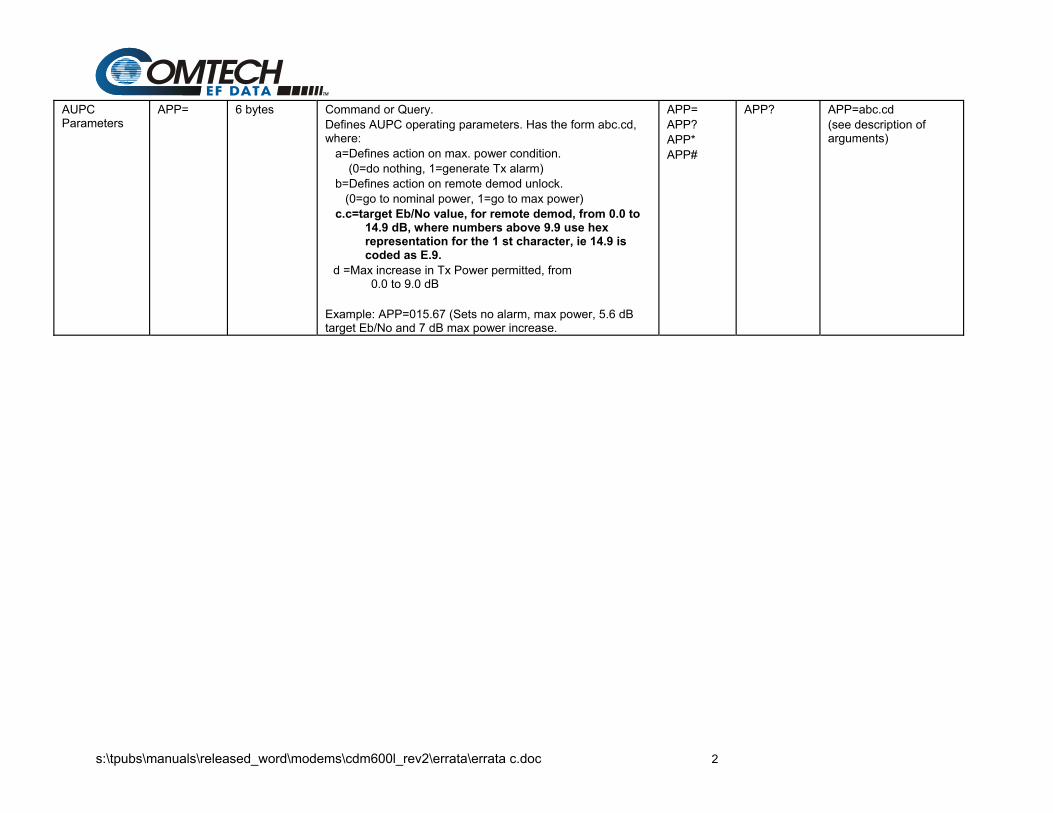
AUPC Parameters
APP=
6 bytes Command or Query. Defines AUPC operating parameters. Has the form abc.cd, where: a=Defines action on max. power condition. (0=do nothing, 1=generate Tx alarm) b=Defines action on remote demod unlock. (0=go to nominal power, 1=go to max power) c.c=target Eb/No value, for remote demod, from 0.0 to
14.9 dB, where numbers above 9.9 use hex representation for the 1 st character, ie 14.9 is coded as E.9.
d =Max increase in Tx Power permitted, from 0.0 to 9.0 dB
Example: APP=015.67 (Sets no alarm, max power, 5.6 dB target Eb/No and 7 dB max power increase.
APP= APP? APP* APP#
APP? APP=abc.cd (see description of arguments)
CDM-600L Open Network Satellite Modem (2.4 kbps – 20 Mbps)
Installation and Operation Manual For Firmware Version 1.3.0 or higher
(see New in this Release – Section 1.5)
Part Number MN/CDM600L.IOM Revision 2
March 9, 2005
Copyright © Comtech EF Data, 2003. All rights reserved. Printed in the USA. Comtech EF Data, 2114 West 7th Street, Tempe, Arizona 85281 USA, 480.333.2200, FAX: 480.333.2161
Comtech EF Data is an ISO 9001 Registered Company.

ii
iii
Table of Contents
ABOUT THIS MANUAL .............................................................................................................. IX CONVENTIONS AND REFERENCES ....................................................................................... IX RECOMMENDED STANDARD DESIGNATIONS ....................................................................... X ELECTRICAL SAFETY................................................................................................................ X TELECOMMUNICATIONS TERMINAL EQUIPMENT DIRECTIVE........................................... XII EMC (ELECTROMAGNETIC COMPATIBILITY) ....................................................................... XII WARRANTY POLICY ............................................................................................................... XIV
CHAPTER 1. INTRODUCTION .............................................................................................1–1 1.1 STANDARD FEATURES ...............................................................................................1–2
1.1.1 AUPC ......................................................................................................................1–2 1.1.2 Software – Flash Upgrading ...................................................................................1–2 1.1.3 Verification ..............................................................................................................1–3 1.1.4 Data Interfaces........................................................................................................1–3
1.2 MAJOR ASSEMBLIES...................................................................................................1–3 1.3 FAST OPTIONS AND HARDWARE OPTIONS .............................................................1–4
1.3.1 FAST Accessible Options .......................................................................................1–5 1.3.2 FAST System Theory..............................................................................................1–5 1.3.3 Implementation .......................................................................................................1–6 1.3.4 Hardware Options ...................................................................................................1–6 1.3.5 Supporting Hardware and Software........................................................................1–7
1.4 COMPATIBILITY............................................................................................................1–7 1.5 NEW IN THIS RELEASE ...............................................................................................1–7
CHAPTER 2. INSTALLATION ..............................................................................................2–1 2.1 UNPACKING..................................................................................................................2–1 2.2 MOUNTING....................................................................................................................2–2 2.3 CONFIGURATION .........................................................................................................2–4 2.4 SELECT INTERNAL IF LOOP .......................................................................................2–4 2.5 CONNECT EXTERNAL CABLES ..................................................................................2–4
CHAPTER 3. FUNCTIONAL DESCRIPTION........................................................................3–1
CHAPTER 4. PHYSICAL DESCRIPTION.............................................................................4–1 4.1 INTRODUCTION............................................................................................................4–1 4.2 FRONT PANEL ..............................................................................................................4–1 4.3 REAR PANEL ................................................................................................................4–2 4.4 DIMENSIONAL ENVELOPE ..........................................................................................4–6
CHAPTER 5. CONNECTOR PINOUTS................................................................................5–1
CDM-600L Satellite Modem Revision 2 Preface MN/CDM600.IOM
iv
5.1 CONNECTOR OVERVIEW............................................................................................5–1 5.2 OVERHEAD INTERFACE CONNECTOR (P3A) ...........................................................5–3 5.3 DATA INTERFACE CONNECTOR (P3B) ......................................................................5–4 5.4 AUDIO INTERFACE CONNECTOR (P4A) ....................................................................5–5 5.5 REMOTE CONTROL INTERFACE CONNECTOR (P4B).............................................5–5 5.6 IDR BACKWARD ALARMS CONNECTOR (P5A) .........................................................5–6 5.7 AUXILIARY SERIAL CONNECTOR (P6).......................................................................5–6 5.8 BALANCED G.703 INTERFACE CONNECTOR (P7)....................................................5–7 5.9 BNC CONNECTORS .....................................................................................................5–7 5.10 UNIT ALARMS (P5B) .................................................................................................5–8 5.11 AC POWER CONNECTOR OPTION .........................................................................5–8 5.12 DC POWER CONNECTOR OPTION.........................................................................5–9 5.13 GROUND CONNECTOR ...........................................................................................5–9
CHAPTER 6. FRONT PANEL OPERATION.........................................................................6–1 6.1 DESCRIPTION...............................................................................................................6–1 6.2 OPENING SCREEN.......................................................................................................6–5 6.3 MAIN MENU...................................................................................................................6–5
6.3.1 CONFIG ..................................................................................................................6–6 6.3.2 TEST.....................................................................................................................6–28 6.3.3 INFORMATION.....................................................................................................6–30 6.3.4 MONITOR .............................................................................................................6–34 6.3.5 STORE/LOAD.......................................................................................................6–39 6.3.6 UTILITIES .............................................................................................................6–40 6.3.7 ODU ......................................................................................................................6–42 6.3.8 FAST.....................................................................................................................6–46
CHAPTER 7. FORWARD ERROR CORRECTION OPTIONS.............................................7–1 7.1 INTRODUCTION............................................................................................................7–1 7.2 VITERBI .........................................................................................................................7–1 7.3 SEQUENTIAL ................................................................................................................7–2 7.4 REED-SOLOMON OUTER CODEC ..............................................................................7–3 7.5 TRELLIS CODING (FAST OPTION)..............................................................................7–5 7.6 TURBO PRODUCT CODEC (HARDWARE OPTION)...................................................7–6 7.7 TPC AND LOW DENSITY PARITY CHECK (LDPC) CODING......................................7–6
7.7.1 Introduction .............................................................................................................7–6 7.7.2 LDPC versus TPC...................................................................................................7–7 7.7.3 End-to-End Processing Delay.................................................................................7–9
7.8 UNCODED OPERATION (NO FEC)............................................................................7–11
CHAPTER 8. OFFSET QPSK OPERATION.........................................................................8–1
CHAPTER 9. OPEN NETWORK OPERATIONS ..................................................................9–1
CDM-600L Satellite Modem Revision 2 Preface MN/CDM600.IOM
v
9.1 INTRODUCTION............................................................................................................9–1 9.2 IBS .................................................................................................................................9–1
9.2.1 IBS Clock/data recovery and De-jitter .....................................................................9–2 9.2.2 IBS Framing ............................................................................................................9–2 9.2.3 IBS Engineering Service Channel...........................................................................9–2 9.2.4 IBS Scrambling .......................................................................................................9–2
9.3 DROP AND INSERT ......................................................................................................9–2 9.3.1 D&I Primary Data Interfaces ...................................................................................9–3 9.3.2 D&I Framing............................................................................................................9–3
9.4 IDR .................................................................................................................................9–4 9.4.1 IDR Primary Data Interfaces ...................................................................................9–5 9.4.2 IDR Engineering Service Channel ..........................................................................9–5
CHAPTER 10. CLOCK MODES AND DROP AND INSERT (D&I) .....................................10–1 10.1 TRANSMIT CLOCKING ...........................................................................................10–1
10.1.1 Internal Clock ........................................................................................................10–1 10.1.2 TX Terrestrial Clock ..............................................................................................10–2 10.1.3 RX Loop-Timed, RX=TX .......................................................................................10–2 10.1.4 RX Loop-Timed, RX<>TX (Asymmetric Loop Timing) ..........................................10–2 10.1.5 External Clock.......................................................................................................10–2 10.1.6 External Reference ...............................................................................................10–3
10.2 RECEIVE CLOCKING ..............................................................................................10–3 10.2.1 Buffer Disabled (RX Satellite) ...............................................................................10–3 10.2.2 Buffer Enabled, TX=RX (TX Terrestrial or External Clock) ...................................10–3 10.2.3 Buffer Enabled, RX<>TX (TX Terrestrial or External Clock) .................................10–3
10.3 X.21 NOTES.............................................................................................................10–3 10.4 DROP AND INSERT ................................................................................................10–6 10.5 FRAME FORMATS ..................................................................................................10–6 10.6 TIME SLOT SELECTION .........................................................................................10–7 10.7 DROP AND INSERT CLOCKING.............................................................................10–8 10.8 RX BUFFER CLOCK = INSERT (D&I ONLY) ..........................................................10–9 10.9 SINGLE-SOURCE MULTIPLE MODEMS ................................................................10–9
CHAPTER 11. EDMAC CHANNEL ......................................................................................11–1 11.1 THEORY OF OPERATION ......................................................................................11–1 11.2 M&C CONNECTION ................................................................................................11–2 11.3 SETUP SUMMARY ..................................................................................................11–3 11.4 DROP & INSERT ++ ................................................................................................11–4
CHAPTER 12. AUTOMATIC UPLINK POWER CONTROL................................................12–1 12.1 INTRODUCTION ......................................................................................................12–1 12.2 SETTING AUPC PARAMETERS .............................................................................12–2
12.2.1 AUPC Target Eb/No..............................................................................................12–2 12.2.2 Max Range, AUPC................................................................................................12–2 12.2.3 Alarm, AUPC.........................................................................................................12–3
CDM-600L Satellite Modem Revision 2 Preface MN/CDM600.IOM
vi
12.2.4 Demod Unlock ......................................................................................................12–3 12.3 COMPENSATION RATE..........................................................................................12–3 12.4 MONITORING ..........................................................................................................12–4
CHAPTER 13. ESC++...........................................................................................................13–1 13.1 INTRODUCTION ......................................................................................................13–1 13.2 OVERHEAD DETAILS .............................................................................................13–1 13.3 AVAILABLE BAUD RATES ......................................................................................13–2 13.4 CONFIGURATION ...................................................................................................13–2 13.5 EFFECT ON EB/NO PERFORMANCE ....................................................................13–2
CHAPTER 14. FLASH UPGRADING ...................................................................................14–1
CHAPTER 15. SUMMARY OF SPECIFICATIONS ..............................................................15–1 15.1 MODULATOR...........................................................................................................15–1 15.2 DEMODULATOR......................................................................................................15–4 15.3 AUTOMATIC UPLINK POWER CONTROL .............................................................15–9 15.4 DATA INTERFACES ................................................................................................15–9 15.5 DATA RATE RANGES ...........................................................................................15–10 15.6 FRAMING SUMMARY............................................................................................15–11 15.7 MISCELLANEOUS .................................................................................................15–11 15.8 APPROVALS..........................................................................................................15–12
CHAPTER 16. REMOTE CONTROL....................................................................................16–1 16.1 INTRODUCTION ......................................................................................................16–1 16.2 RS-485 .....................................................................................................................16–1 16.3 RS-232 .....................................................................................................................16–2 16.4 BASIC PROTOCOL..................................................................................................16–2 16.5 PACKET STRUCTURE ............................................................................................16–3
16.5.1 Start Of Packet......................................................................................................16–3 16.5.2 Address.................................................................................................................16–3 16.5.3 Instruction Code....................................................................................................16–4 16.5.4 Instruction Code Qualifier .....................................................................................16–4 16.5.5 Message Arguments .............................................................................................16–5 16.5.6 End Of Packet.......................................................................................................16–5
16.6 REMOTE COMMANDS............................................................................................16–6 16.6.1 TX Remote Commands ........................................................................................16–7 16.6.2 RX Remote Commands ......................................................................................16–13 16.6.3 Unit Remote Commands.....................................................................................16–20 16.6.4 Query Commands...............................................................................................16–27 16.6.5 Bulk Commands..................................................................................................16–33 16.6.6 BUC Commands .................................................................................................16–36 16.6.7 LNB Commands..................................................................................................16–39
CDM-600L Satellite Modem Revision 2 Preface MN/CDM600.IOM
vii
CHAPTER 17. BUC FSK COMMUNICATIONS ...................................................................17–1 17.1 INTRODUCTION ......................................................................................................17–1
17.1.1 Transmission Interface..........................................................................................17–2 17.2 MESSAGE STRUCTURE.........................................................................................17–2
17.2.1 Command Message Structure (CDM-600L to BUC).............................................17–2 17.2.2 Response Message Structure (BUC to CDM-600L) .............................................17–3
17.3 BUC POWER CLASS...............................................................................................17–3 17.4 BUC OUTPUT POWER LEVELING .........................................................................17–4
CHAPTER 18. DST SETUP..................................................................................................18–1 18.1 INITIAL OPERATION ...............................................................................................18–1
18.1.1 Prior to Turning On Power ....................................................................................18–1 18.1.2 Initial Power Up – Modem Only ............................................................................18–2
18.2 LO, MIX AND SPECTRUM (INVERSION) SETTINGS.............................................18–3 18.3 APPLYING POWER TO THE BUC ..........................................................................18–4 18.4 INITIAL OPERATION OF THE MODEM WITH THE BUC AND LNB.......................18–5
APPENDIX A. CABLE DRAWINGS ...................................................................................... A–1
APPENDIX B. EB/NO MEASUREMENT ............................................................................... B–1
APPENDIX C. FAST ACTIVATION PROCEDURE............................................................... C–1 C.1 INTRODUCTION........................................................................................................... C–1 C.2 ACTIVATION PROCEDURE......................................................................................... C–1
C.2.1 Serial Number ........................................................................................................ C–1 C.2.2 View currently installed features ............................................................................ C–2 C.2.3 Enter Access Codes .............................................................................................. C–2
INDEX .......................................................................................................................I–1
Figures Figure 1-1. CDM-600L L-Band Satellite Modem......................................................................................1–1 Figure 2-1. Installation of the Optional Mounting Bracket, KT/6228-2.....................................................2–3 Figure 3-1. CDM-600L Modem Block Diagram........................................................................................3–2 Figure 4-1. CDM-600L Front Panel..........................................................................................................4–1 Figure 4-2. CDM-600L Rear Panel ..........................................................................................................4–2 Figure 4-3. CDM-600L Dimensional Envelope .........................................................................................4–6 Figure 6-1. Front Panel View ...................................................................................................................6–1 Figure 6-2. Keypad...................................................................................................................................6–3 Figure 6-3. CDM-600L Menu Trees .........................................................................................................6–4 Figure 6-4. Loopback Modes .................................................................................................................6–29 Figure 7-1. Viterbi Decoding ..................................................................................................................7–13 Figure 7-2. Sequential Decoding 64 kbps.............................................................................................7–14 Figure 7-3. Sequential Decoding 1024 kbps..........................................................................................7–15 Figure 7-4. Sequential Decoding 2048 kbps..........................................................................................7–16
CDM-600L Satellite Modem Revision 2 Preface MN/CDM600.IOM
viii
Figure 7-5. Viterbi with concatenated R-S Outer Code .........................................................................7–17 Figure 7-6. Sequential with concatenated R-S Outer Code...................................................................7–18 Figure 7-7. 8-PSK/TCM Rate 2/3 with and without concatenated Reed-Solomon Outer Code ............7–19 Figure 7-8. Comtech EF Data Turbo Product Codec Rate 3/4 QPSK/OQPSK, 8-PSK and 16-QAM..7–20 Figure 7-9. Comtech EF Data Turbo Product Codec Rate 7/8 QPSK/OQPSK, 8-PSK and 16-QAM..7–21 Figure 7-10. Rate 1/2 QPSK, Rate 0.95 QPSK and Rate 0.95 8-PSK ..................................................7–22 Figure 7-11. Rate 21/44 BPSK and Rate 5/16 BPSK Turbo..................................................................7–23 Figure 7-12. 16-QAM Viterbi, Rate 3/4 and Rate 7/8 with 220,200 Reed-Solomon Outer Code ..........7–24 Figure 7-13. Differential Encoding - No FEC, No Scrambling................................................................7–25 Figure 7-14. LDPC, Rate 1/2, BPSK, (O)QPSK.....................................................................................7–26 Figure 7-15. LDPC, Rate 2/3, (O)QPSK/8-PSK/8-QAM ........................................................................7–27 Figure 7-16. LDPC, Rate 3/4, (O)QPSK/8-QAM....................................................................................7–28 Figure 7-17. LDPC, Rate 3/4, 8-PSK / 8-QAM.......................................................................................7–29 Figure 10-1 Tx Clock Modes..................................................................................................................10–4 Figure 10-2 Rx Clock Modes .................................................................................................................10–5 Figure 10-3 Supported T1 and E1 Framing Formats.............................................................................10–6 Figure 10-4 Drop and Insert Clocking ....................................................................................................10–8 Figure 10-5. Single-Source Multiple Modems (Looming) ....................................................................10–10
Tables Table 5-1. CDM-600L External Connections ...........................................................................................5–2 Table 5-2. Overhead Interface Connector Pin Assignments ...................................................................5–3 Table 5-3. Data Interface Connector Pin Assignments............................................................................5–4 Table 5-4. Audio Interface Connector Pin Assignments ..........................................................................5–5 Table 5-5. Remote Control Interface Connector Pin Assignments.........................................................5–5 Table 5-6. IDR Alarm Interface Connector Pin Assignments..................................................................5–6 Table 5-7. Auxiliary Serial Connector (USB Type B Socket) ...................................................................5–6 Table 5-8. Balanced G.703 Interface Connector Pin Assignments .........................................................5–7 Table 5-9. BNC Connectors .....................................................................................................................5–7 Table 5-10. Alarm Interface Connector Pin Assignments.......................................................................5–8 Table 6-1. Front Panel LED Indicators.....................................................................................................6–2 Table 7-1. Viterbi Decoding Summary .....................................................................................................7–2 Table 7-2. Sequential Decoding Summary ..............................................................................................7–3 Table 7-3. Concatenated Reed-Solomon Coding Summary ...................................................................7–4 Table 7-4. 8-PSK/TCM Coding Summary................................................................................................7–5 Table 7-5. Available TPC and LDPC Modes............................................................................................7–8 Table 7-6. Turbo Product Coding Processing Delay Comparison...........................................................7–9 Table 7-7. TPC and LDPC Summary.....................................................................................................7–11
ix
Preface
About this Manual
This manual provides installation and operation information for the Comtech EF Data CDM-600L satellite modem. This is a technical document intended for earth station engineers, technicians, and operators responsible for the operation and maintenance of the CDM-600L.
Conventions and References
Metric Conversion
Metric conversion information is located on the inside back cover of this manual. This information is provided to assist the operator in cross-referencing English to Metric conversions.
Cautions and Warnings
IMPORTANT Indicates information critical for proper equipment function.
WARNING
WARNING indicates a potentially hazardous situation that, if not avoided, could result in death or serious injury.
CDM-600L Satellite Modem Revision 2 Preface MN/CDM600.IOM
x
Reporting Comments or Suggestions Concerning this Manual
Comments and suggestions regarding the content and design of this manual will be appreciated. To submit comments, please contact the Comtech EF Data Technical Publications Department: [email protected]
Recommended Standard Designations
Recommended Standard (RS) is equivalent to the Electronic Industries Association (EIA) designation. Either designation is acceptable. However, Comtech EF Data has decided that only one reference designator, either RS or EIA, may be used in a manual.
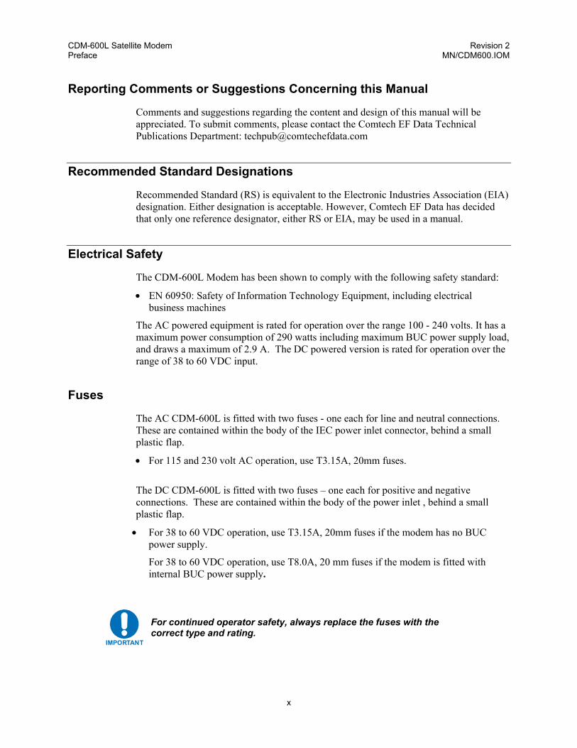
Electrical Safety
The CDM-600L Modem has been shown to comply with the following safety standard:
• EN 60950: Safety of Information Technology Equipment, including electrical business machines
The AC powered equipment is rated for operation over the range 100 - 240 volts. It has a maximum power consumption of 290 watts including maximum BUC power supply load, and draws a maximum of 2.9 A. The DC powered version is rated for operation over the range of 38 to 60 VDC input.
Fuses
The AC CDM-600L is fitted with two fuses - one each for line and neutral connections. These are contained within the body of the IEC power inlet connector, behind a small plastic flap.
• For 115 and 230 volt AC operation, use T3.15A, 20mm fuses.
The DC CDM-600L is fitted with two fuses – one each for positive and negative connections. These are contained within the body of the power inlet , behind a small plastic flap.
• For 38 to 60 VDC operation, use T3.15A, 20mm fuses if the modem has no BUC power supply.
For 38 to 60 VDC operation, use T8.0A, 20 mm fuses if the modem is fitted with internal BUC power supply.
IMPORTANT
For continued operator safety, always replace the fuses with the correct type and rating.
CDM-600L Satellite Modem Revision 2 Preface MN/CDM600.IOM
xi
Environmental
The CDM-600L must not be operated in an environment where the unit is exposed to extremes of temperature outside the ambient range 0 to 50°C (32° to 122°F), precipitation, condensation, or humid atmospheres above 95% RH, altitudes (un-pressurised) greater than 2000 metres, excessive dust or vibration, flammable gases, corrosive or explosive atmospheres. Operation in vehicles or other transportable installations that are equipped to provide a stable environment is permitted. If such vehicles do not provide a stable environment, safety of the equipment to EN60950 may not be guaranteed.
Installation
AC Modem Installation: The installation and connection to the line supply must be made in compliance to local or national wiring codes and regulations. The CDM-600L is designed for connection to a power system that has separate ground, line and neutral conductors. The equipment is not designed for connection to power system that has no direct connection to ground. The CDM-600L is shipped with a line inlet cable suitable for use in the country of operation. If it is necessary to replace this cable, ensure the replacement has an equivalent specification. Examples of acceptable ratings for the cable include HAR, BASEC and HOXXX-X. Examples of acceptable connector ratings include VDE, NF-USE, UL, CSA, OVE, CEBEC, NEMKO, DEMKO, BS1636A, BSI, SETI, IMQ, KEMA-KEUR and SEV. International Symbols:
Symbol Definition Symbol Definition
~ Alternating Current
Protective Earth
Fuse
Chassis Ground
DC Modem Installation: The DC input CDM-600L is connected to a nominal 48 VDC prime power source. The DC input is isolated from the chassis and from the DC output to the BUC if equipped with internal BUC power supply. The chassis may be connected to a local system ground
CDM-600L Satellite Modem Revision 2 Preface MN/CDM600.IOM
xii
using a separate wire to the ground stud on the back of the chassis. Since the DC input is isolated, either the positive or the negative side of the DC input may be common with local ground. Labeling on the back of the chassis indicates the positive and negative terminals of the input power socket. The modem is supplied with a 2-wire power cable (CEFD part number CA/WR10327-1) with one end terminated with a connector that mates with the modem input power socket. Positive DC input is on the red wire, while negative DC input is on the black wire. The DC input connector is Molex PN 03-12-1026 with Molex PN 08-12-1222 pins.
Telecommunications Terminal Equipment Directive
In accordance with the Telecommunications Terminal Equipment Directive 91/263/EEC, this equipment should not be directly connected to the Public Telecommunications Network.
EMC (Electromagnetic Compatibility)
In accordance with European Directive 89/336/EEC, the CDM-600L Modem has been shown, by independent testing, to comply with the following standards: Emissions: EN 55022 Class B - Limits and methods of measurement of radio
interference characteristics of Information Technology Equipment.
(Also tested to FCC Part 15 Class B) Immunity: EN 50082 Part 1 - Generic immunity standard, Part 1: Domestic,
commercial and light industrial environment. Additionally, the CDM-600L has been shown to comply with the following standards:
EN 61000-3-2 Harmonic Currents Emission EN 61000-3-3 Voltage Fluctuations and Flicker EN 61000-4-2 ESD Immunity EN 61000-4-4 EFT Burst Immunity EN 61000-4-5 Surge Immunity EN 61000-4-6 RF Conducted Immunity EN 61000-4-8 Power frequency Magnetic Field Immunity EN 61000-4-9 Pulse Magnetic Field Immunity EN 61000-4-11 Voltage Dips, Interruptions, and Variations Immunity EN 61000-4-13 Immunity to Harmonics
In order that the Modem continues to comply with these standards, observe the following instructions:
IMPORTANT
CDM-600L Satellite Modem Revision 2 Preface MN/CDM600.IOM
xiii
• Connections to the transmit and receive IF ports (Type N or Type F connectors) should be made using a good quality coaxial cable - for example 50 Ω or 75 Ω.
• All 'D' type connectors attached to the rear panel must have back-shells that provide
continuous metallic shielding. Cable with a continuous outer shield (either foil or braid, or both) must be used, and the shield must be bonded to the backshell.
• The equipment must be operated with its cover on at all times. If it becomes necessary
to remove the cover, the user should ensure that the cover is correctly re-fitted before normal operation commences.
CDM-600L Satellite Modem Revision 2 Preface MN/CDM600.IOM
xiv
Warranty Policy
This Comtech EF Data product is warranted against defects in material and workmanship for a period of two years from the date of shipment. During the warranty period, Comtech EF Data will, at its option, repair or replace products that prove to be defective. For equipment under warranty, the customer is responsible for freight to Comtech EF Data and all related custom, taxes, tariffs, insurance, etc. Comtech EF Data is responsible for the freight charges only for return of the equipment from the factory to the customer. Comtech EF Data will return the equipment by the same method (i.e., Air, Express, Surface) as the equipment was sent to Comtech EF Data.
Limitations of Warranty
The foregoing warranty shall not apply to defects resulting from improper installation or maintenance, abuse, unauthorized modification, or operation outside of environmental specifications for the product, or, for damages that occur due to improper repackaging of equipment for return to Comtech EF Data. No other warranty is expressed or implied. Comtech EF Data specifically disclaims the implied warranties of merchantability and fitness for particular purpose.
Exclusive Remedies
The remedies provided herein are the buyer's sole and exclusive remedies. Comtech EF Data shall not be liable for any direct, indirect, special, incidental, or consequential damages, whether based on contract, tort, or any other legal theory.
Disclaimer
Comtech EF Data has reviewed this manual thoroughly in order that it will be an easy-to-use guide to your equipment. All statements, technical information, and recommendations in this manual and in any guides or related documents are believed reliable, but the accuracy and completeness thereof are not guaranteed or warranted, and they are not intended to be, nor should they be understood to be, representations or warranties concerning the products described. Further, Comtech EF Data reserves the right to make changes in the specifications of the products described in this manual at any time without notice and without obligation to notify any person of such changes. If you have any questions regarding your equipment or the information in this manual, please contact the Comtech EF Data Customer Support Department.
1–1
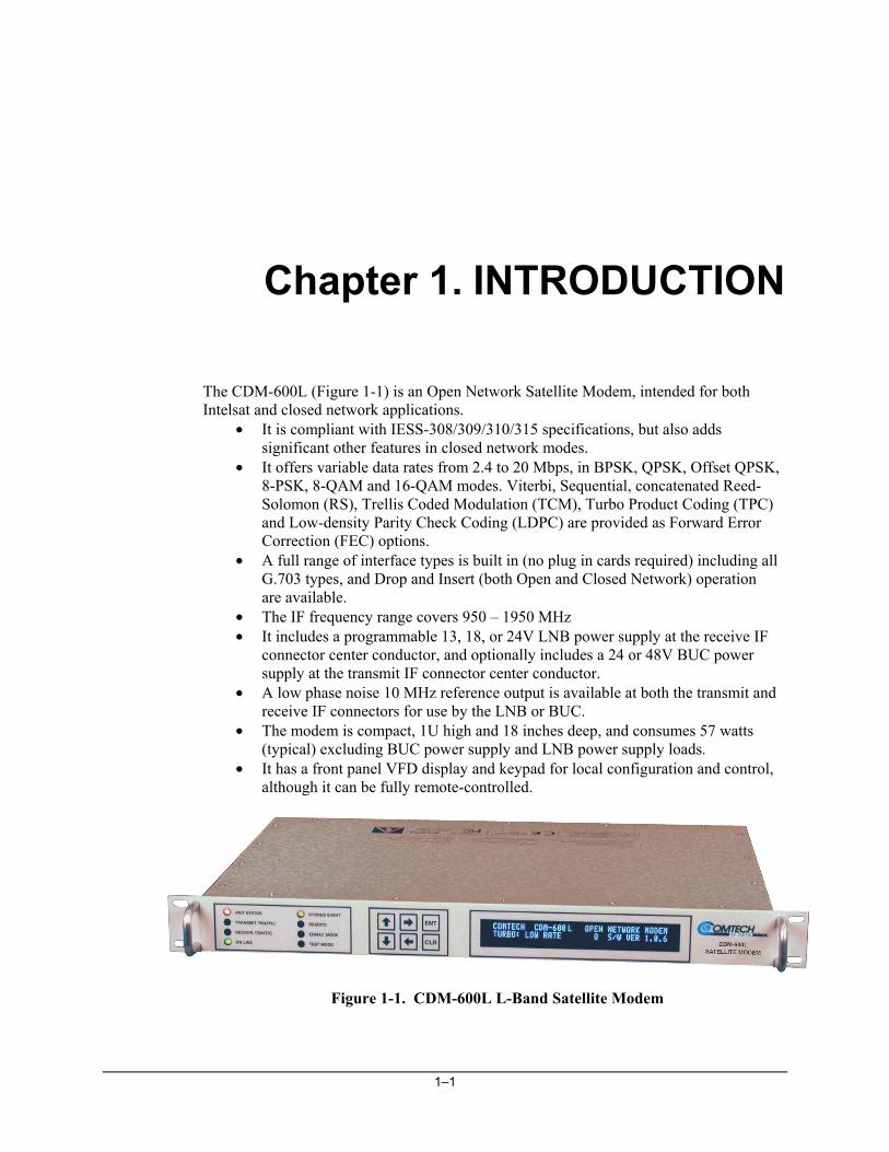
Chapter 1. INTRODUCTION
The CDM-600L (Figure 1-1) is an Open Network Satellite Modem, intended for both Intelsat and closed network applications.
• It is compliant with IESS-308/309/310/315 specifications, but also adds significant other features in closed network modes.
• It offers variable data rates from 2.4 to 20 Mbps, in BPSK, QPSK, Offset QPSK, 8-PSK, 8-QAM and 16-QAM modes. Viterbi, Sequential, concatenated Reed-Solomon (RS), Trellis Coded Modulation (TCM), Turbo Product Coding (TPC) and Low-density Parity Check Coding (LDPC) are provided as Forward Error Correction (FEC) options.
• A full range of interface types is built in (no plug in cards required) including all G.703 types, and Drop and Insert (both Open and Closed Network) operation are available.
• The IF frequency range covers 950 – 1950 MHz • It includes a programmable 13, 18, or 24V LNB power supply at the receive IF
connector center conductor, and optionally includes a 24 or 48V BUC power supply at the transmit IF connector center conductor.
• A low phase noise 10 MHz reference output is available at both the transmit and receive IF connectors for use by the LNB or BUC.
• The modem is compact, 1U high and 18 inches deep, and consumes 57 watts (typical) excluding BUC power supply and LNB power supply loads.
• It has a front panel VFD display and keypad for local configuration and control, although it can be fully remote-controlled.
Figure 1-1. CDM-600L L-Band Satellite Modem
CDM-600L Satellite Modem Revision 2 Introduction MN/CDM600L.IOM
1–2
1.1 Standard Features
The CDM-600L provides a wealth of standard features which go far beyond the basic requirements of the Intelsat specifications.
• Low rate variable data rates – 2.4 kbps to 5.0 Mbps • Mid-rate variable data rates – 2.4 kbps to 10.0 Mbps • High-rate variable data rates – 2.4 kbps to 20.0 Mbps • Embedded Distant-end Monitor and Control (EDMAC) (see Note) • Asymmetric Loop Timing • Automatic Uplink Power Control (AUPC) • Software – Flash Upgrading • Modulation Types –BPSK, QPSK, and OQPSK • 1:1 and 1:10 redundancy switches
Note: In EDMAC mode, an additional 5% overhead is combined with the traffic data, (1.5% in Turbo BPSK modes, Turbo Rate 1/2 QPSK/OQPSK, and all data rates greater than 2 Mbps) which permits Monitor & Control (M&C) information to be added (transparently to the user), allowing access to the distant-end modem. This mode does not require any additional cabling at either the local or distant-end modems - access to EDMAC is via the standard M&C control port. Full M&C is possible, and importantly, the on/off status of the carrier at the distant-end carrier can be controlled. In addition, for firmware version 1.2.0 and higher, the proprietary D&I++ framing mode is available. This combines Drop & Insert (D&I) operation with a similar EDMAC link and a 2.2% overhead.
1.1.1 AUPC
An important innovation in the CDM-600L is the addition of Automatic Uplink Power Control (AUPC). This feature enables the modem to automatically adjust its output power to maintain the Eb/No of the remote end of the satellite link constant. This provides protection against rain fading, a particularly severe problem with Ku-band links. To accomplish this, either the EDMAC or D&I++ or ESC++ framing types may be used, and the distant end modem constantly sends back information about the demodulator Eb/No using reserved bytes in the overhead structure. Using the Eb/No, the local modem then adjusts its output power, and hence, a closed-loop feedback system is created over the satellite link. A benefit of this AUPC feature is that the remote demodulator’s Eb/No can be viewed from the front panel display of the local modem.
1.1.2 Software – Flash Upgrading
The internal software is both powerful and flexible, permitting storage and retrieval of up to 10 different modem configurations. The modem uses ‘flash memory’ technology internally, and new firmware can be uploaded to the unit from an external PC. This
CDM-600L Satellite Modem Revision 2 Introduction MN/CDM600L.IOM
1–3
simplifies software upgrading, and updates can now be sent via the Internet, e-mail, or on disk. The upgrade can be performed without opening the unit by simply connecting the modem to the serial port of a computer. Refer to Chapter 13 for addition information.
1.1.3 Verification
The unit includes many test modes and loopbacks for rapid verification of the correct functioning of the unit. Of particular note is the IF loopback, which permits the user to perform a quick diagnostic test without having to disturb external cabling. During the loopback, all of the receive configuration parameters are temporarily changed to match those of the transmit side, and an internal RF switch connects the modulator output to the demodulator input. When normal operation is again selected, all of the previous values are restored.
1.1.4 Data Interfaces
The CDM-600L includes, as standard, a universal data interface that eliminates the need to exchange interface cards for different applications. The interfaces offered include:
• RS-422 (RS-530) DCE (at rates up to 10 Mbps) • X.21 DTE and DCE (at rates up to 10 Mbps) • V.35 DCE (at rates up to 10 Mbps) • Synchronous RS-232 DCE (at rates up to 300 kbps) • G.703 E1, balanced and unbalanced • G.703 T1, balanced • G.703 E2, balanced and unbalanced • G.703 T2, balanced • Serial LVDS (at rates up to 20 Mbps) • Dual Audio, 600Ω (produces a single 64 kbps IBS data stream)
1.2 Major Assemblies
Assembly Description PL/9662-1 0.02 PPM Reference Modem Card – 75Ω receive Type F PL/9662-2 1 PPM Reference Modem Card – 75Ω receive Type F PL/9662-3 0.02 PPM Reference Modem Card – 50Ω receive Type N PL/9662-4 1 PPM Reference Modem Card – 50Ω receive Type N AS/0463 Turbo Codec – low rate AS/9436 Turbo Codec – high rate PL/10341-1 LDPC and High RateTurbo Codec PL/9076-1 Baseband Framing Card PL/9640-1 Chassis
CDM-600L Satellite Modem Revision 2 Introduction MN/CDM600L.IOM
1–4
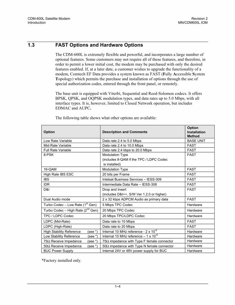
1.3 FAST Options and Hardware Options
The CDM-600L is extremely flexible and powerful, and incorporates a large number of optional features. Some customers may not require all of these features, and therefore, in order to permit a lower initial cost, the modem may be purchased with only the desired features enabled. If, at a later date, a customer wishes to upgrade the functionality of a modem, Comtech EF Data provides a system known as FAST (Fully Accessible System Topology) which permits the purchase and installation of options through the use of special authorization codes, entered through the front panel, or remotely. The base unit is equipped with Viterbi, Sequential and Reed-Solomon codecs. It offers BPSK, QPSK, and OQPSK modulation types, and data rates up to 5.0 Mbps, with all interface types. It is, however, limited to Closed Network operation, but includes EDMAC and AUPC. The following table shows what other options are available:
Option Description and Comments Option Installation Method
Low Rate Variable Data rate 2.4 to 5.0 Mbps BASE UNIT Mid-Rate Variable Data rate 2.4 to 10.0 Mbps FAST Full Rate Variable Data rate 2.4 kbps to 20.0 Mbps FAST 8-PSK Modulation Type
(includes 8-QAM if the TPC / LDPC Codec is installed)
FAST
16-QAM Modulation Type FAST High Rate IBS ESC 20 bits per Frame FAST IBS Intelsat Business Services – IESS-309 FAST IDR Intermediate Data Rate – IESS-308 FAST D&I Drop and Insert
(includes D&I++, S/W Ver 1.2.0 or higher) FAST
Dual Audio mode 2 x 32 kbps ADPCM Audio as primary data FAST Turbo Codec – Low Rate (1st Gen) 5 Mbps TPC Codec Hardware Turbo Codec – High Rate (2nd Gen) 20 Mbps TPC Codec Hardware TPC / LDPC Codec 20 Mbps TPC/LDPC Codec Hardware LDPC (Mid-Rate) Data rate to 10 Mbps FAST LDPC (High-Rate) Data rate to 20 Mbps FAST High Stability Reference (see *) Internal 10 MHz reference - 2 x 10⁻⁸ Hardware Low Stability Reference (see *) Internal 10 MHz reference – 1 x 10⁻⁶ Hardware 75Ω Receive Impedance (see *) 75Ω impedance with Type F female connector Hardware 50Ω Receive Impedance (see *) 50Ω impedance with Type N female connector Hardware BUC Power Supply Internal 24V or 48V power supply for BUC Hardware
*Factory installed only.
CDM-600L Satellite Modem Revision 2 Introduction MN/CDM600L.IOM
1–5
In order to operate in Turbo (TPC) Mode: To operate in the Low Rate range (up to 5 Mbps), the modem requires any of the three Codec cards to be installed. To operate in the Mid- or High-Rate ranges (up to 10 or 20 Mbps), the modem requires either the High Rate TPC Codec or the TPC / LDPC Codec to be installed. In order to operate in LDPC Mode: The unit will require the TPC/LDPC Codec to be installed. In the base configuration this will provide LDPC up to 5 Mbps. In order to operate at higher data rates, there are two additional FAST options available that permit operation up to 10 Mbps or 20 Mbps. Note that these are in addition to the base modem rate options. In order to operate in 8-QAM mode: The modem will require the TPC/LDPC Codec to be installed and have the 8-PSK / 8-QAM FAST option enabled. For example, if LDPC operation at 20 Mbps, 8-QAM mode is required, the modem must be configured with the following: • TPC/LDPC Codec hardware option • Full rate variable FAST option • High-Rate LDPC FAST option • 8-PSK /8-QAM FAST option
1.3.1 FAST Accessible Options
Comtech EF Data’s FAST system allows immediate implementation of different options through the user interface keypad. All FAST options are available through the basic platform unit.
1.3.2 FAST System Theory
FAST is an enhancement feature available in Comtech EF Data products, enabling on-location upgrade of the operating feature set - in the rack - without removing a modem from the setup. When service requirements change, the operator can upgrade the topology of the modem to meet those requirements within minutes after confirmation by Comtech EF Data. This accelerated upgrade can be accomplished only because of FAST’s extensive use of programmable devices incorporating Comtech EF Data-proprietary signal processing techniques. These techniques allow the use of a unique access code to enable configuration of the available hardware. The access code can be purchased at any time from Comtech EF Data. Once obtained, the access code is loaded into the unit through the front panel keyboard or the rear remote port.
CDM-600L Satellite Modem Revision 2 Introduction MN/CDM600L.IOM
1–6
With the exclusive FAST technology, operators have maximum flexibility for enabling functions as they are required. FAST allows an operator to order a modem precisely tailored for the initial application.
1.3.3 Implementation
FAST is factory-implemented in the modem at the time of order. Hardware options for basic modems can be ordered and installed either at the factory or in the field. The operator can select options that can be activated easily in the field, depending on the current hardware configuration of the modem. The Activation Procedure is described in Appendix C.
1.3.4 Hardware Options
There are seven hardware options available. There are two Comtech EF Data Turbo Product Codecs, and a combination TPC(Turbo) and Low-Density Parity Check (LDPC) codec, representing a very significant development in the area of FEC. They are plug-in daughter cards (SIMM modules), field upgradeable. The Low Rate (1st Generation) TPC option provides data rate capability up to 5 Mbps, and code rates limited to Rate 5/16 (BPSK), Rate 21/44 (BPSK) and Rate 3/4 (QPSK, OQPSK, 8-PSK and 16-QAM). The High Rate (2nd Generation) TPC option provides data rate capability up to 20 Mbps, in addition to Rate 7/8 and Rate 0.95 capability. The combination Low-density Parity Check (LDPC) and TPC Codec is capable of data rates up to 20 Mbps, and provides Rate 1/2, Rate 2/3 and Rate 3/4 code rates across the range of modulation types. The fourth hardware option is the Internal Reference Stability. The high stability option includes a 2 x 10⁻⁸ 10 MHz reference oscillator on the modem board, while the low stability option places a 1 x 10⁻⁶ 10 MHz reference on the modem board. This option must be fitted in the factory at the time of order. The fifth hardware option is the Receive IF Impedance and Connector. The receive IF may be configured with either a Type F female connector at 75Ω impedance, or a Type N female connector at 50Ω impedance. This option must also be fitted in the factory at the time of order. The sixth hardware option is prime power input for the modem. The modem chassis may be configured for either 100-240 VAC input, or 38-60 VDC input. The seventh hardware option is an internal power supply for the BUC. This power supply provides 24V (100W max.) or 48V (180W max.) power to the BUC on the center conductor of the transmit cable. This hardware option can be fitted in the factory at the time of order, or be installed in the field as an upgrade kit. The options include 100-240 VAC input, or 38-60 VDC input.
CDM-600L Satellite Modem Revision 2 Introduction MN/CDM600L.IOM
1–7
1.3.5 Supporting Hardware and Software
The CDM-600L incorporates an FSK serial link that can be activated on the TX-IF port for the purpose of communicating with an FSK capable BUC. In this manner, a user may monitor, configure, and control the BUC using the front panel display and keypad of the modem or the modem’s remote control interface. The EDMAC channel can be used to convey M&C interface to a BUC at the distant end of a satellite link if it is connected to a CDM-600L. This FSK interface with the BUC includes a BUC output power leveling mode where the modem M&C monitors the detected BUC output power level reported on the FSK link, and automatically adjusts the modem transmit output power to maintain a constant BUC transmit output level. The CDM-600L is supported by Comtech EF Data’s SatMac software, a Windows TM based application that provides a ‘point and click’ interface for complete systems of Comtech equipment, comprising Modems, Transceivers, and Redundancy Switches. For more information, or to order a free demo disk, contact the factory.
1.4 Compatibility
The CDM-600L is fully backwards-compatible with the Comtech EF Data CDM-500, CDM-550, CDM-550T, and CDM-600 modems. Being an Open Network Modem, the CDM-600L is fully compatible with modems from other manufacturers that are compliant with the IESS-308/-309/-310/-314/-315 specifications.
1.5 New in this Release
Revision 2 of this document includes information on the the following new features:
* Low-Density Parity Check (LDPC) Codec (supported in Firmware Version 1.3.0 onwards). This is the latest form of Forward Error Correction, giving enhanced performance when compared to some TPC modes. This is a plug-in module that also includes all of the 2nd Generation TPC (Turbo) functionality. Please see Chapter 7 for more details. * 8-QAM – a new modulation scheme included specifically to replace 8-PSK when LDPC is used. It is only available when the LDPC codec is installed, and is supported in Firmware Version 1.3.0 onwards. Please see Chapter 7 for more details. * A higher-throughput ESC type, called ESC++ . This new mode permits an async ESC rate of up 38.4 kbaud at a user data rate of 512 kbps (up to 4.8 kbaud at 64 kbps), while simultaneously permitting AUPC operation. This naturally uses more overhead than previous modes, although the percentage overhead reduces significantly at higher data rates. This is now a standard feature in Firmware Version 1.3.0 onwards. Please see Chapter 13 for more details.
CDM-600L Satellite Modem Revision 2 Introduction MN/CDM600L.IOM
1–8
* A Power-On, Carrier-Off (POCO) feature has been added to the Factory Menu.
* When this option is set to OFF, the CDM-600L will power-up with the Tx Carrier in the last known state. (For example, if the Tx Carrier was ON, and then the power is cycled, the Tx Carrier will be turned ON once more.) NOTE THAT THIS IS THE DEFAULT OPERATING MODE OF THE CDM-600, AND IT IS RECOMMENDED THAT THE USER LEAVE THE UNIT CONFIGURED IN THIS WAY.
* When this option is set to ON, the CDM-600L will always power-up with the Tx Carrier in the OFF state. The user must then, either through the front panel, or the remote control port, turn the Carrier ON in order for the unit to transmit a carrier.
Consult the factory for details of how to access the Factory Menu.
2–1
Chapter 2. INSTALLATION
2.1 Unpacking
Inspect shipping containers for damage. If shipping containers are damaged, keep them until the contents of the shipment have been carefully inspected and checked for normal operation. The modem and manual are packaged in pre-formed, reusable, cardboard cartons containing foam spacing for maximum shipping protection.
CAUTION
Do not use any cutting tool that will extend more than 1 inch into the container. This can cause damage to the modem.
Unpack the modem as follows:
1. Cut the tape at the top of the carton indicated by OPEN THIS END.
2. Remove the cardboard/foam space covering the modem.
3. Remove the modem, manual, and power cord from the carton.
4. Save the packing material for storage or reshipment purposes.
5. Inspect the equipment for any possible damage incurred during shipment.
6. Check the equipment against the packing list to ensure the shipment is correct.
7. Refer to the following sections for further installation instructions.
CDM-600L Satellite Modem Revision 2 Installation MN/CDM600L.IOM
2–2
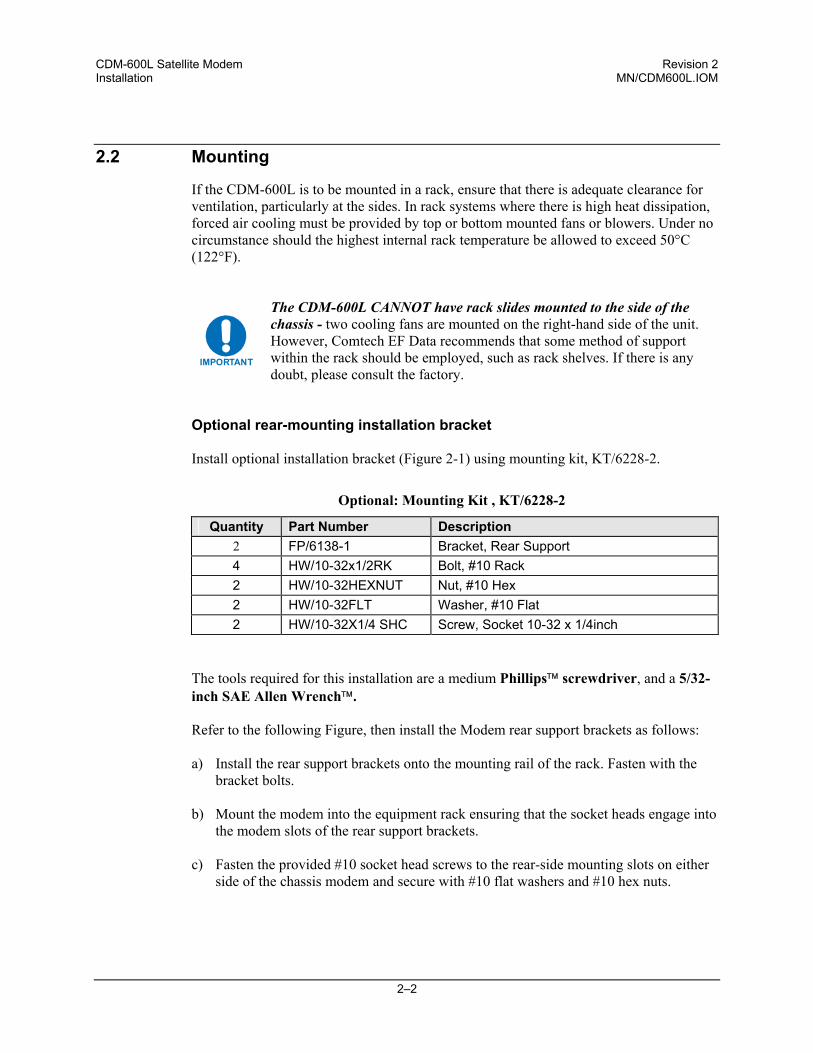
2.2 Mounting
If the CDM-600L is to be mounted in a rack, ensure that there is adequate clearance for ventilation, particularly at the sides. In rack systems where there is high heat dissipation, forced air cooling must be provided by top or bottom mounted fans or blowers. Under no circumstance should the highest internal rack temperature be allowed to exceed 50°C (122°F).
IMPORTANT
The CDM-600L CANNOT have rack slides mounted to the side of the chassis - two cooling fans are mounted on the right-hand side of the unit. However, Comtech EF Data recommends that some method of support within the rack should be employed, such as rack shelves. If there is any doubt, please consult the factory.
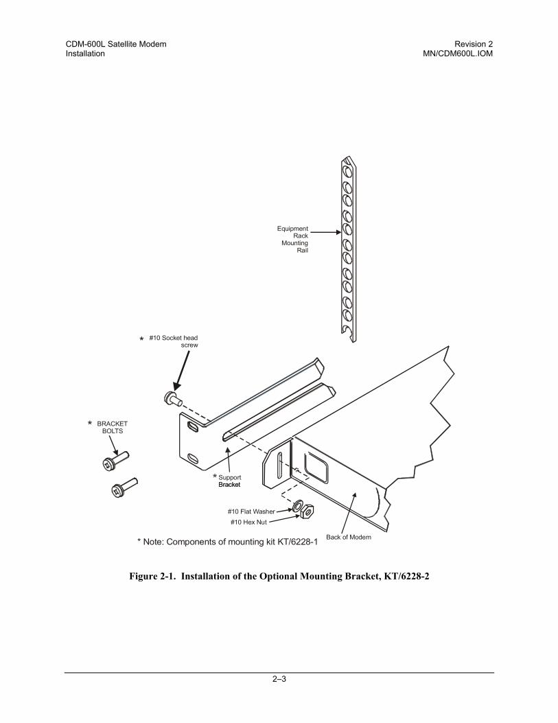
Optional rear-mounting installation bracket Install optional installation bracket (Figure 2-1) using mounting kit, KT/6228-2.
Optional: Mounting Kit , KT/6228-2
Quantity Part Number Description 2 FP/6138-1 Bracket, Rear Support 4 HW/10-32x1/2RK Bolt, #10 Rack 2 HW/10-32HEXNUT Nut, #10 Hex 2 HW/10-32FLT Washer, #10 Flat 2 HW/10-32X1/4 SHC Screw, Socket 10-32 x 1/4inch
The tools required for this installation are a medium Phillips screwdriver, and a 5/32-inch SAE Allen Wrench.
Refer to the following Figure, then install the Modem rear support brackets as follows: a) Install the rear support brackets onto the mounting rail of the rack. Fasten with the
bracket bolts.
b) Mount the modem into the equipment rack ensuring that the socket heads engage into the modem slots of the rear support brackets.
c) Fasten the provided #10 socket head screws to the rear-side mounting slots on either side of the chassis modem and secure with #10 flat washers and #10 hex nuts.
CDM-600L Satellite Modem Revision 2 Installation MN/CDM600L.IOM
2–3
Figure 2-1. Installation of the Optional Mounting Bracket, KT/6228-2
EquipmentRack
MountingRail
#10 Socket headscrew
BRACKETBOLTS
SupportBracket
Back of Modem* Note: Components of mounting kit KT/6228-1
*
*
*
Bracket
#10 Flat Washer#10 Hex Nut
CDM-600L Satellite Modem Revision 2 Installation MN/CDM600L.IOM
2–4
2.3 Configuration
There are no internal jumpers to configure, no interface cards to install, and no other options to install. All configuration is carried out entirely in software. The unit should first be configured locally, using the front panel keypad and display. The unit will ship with a default 64 kbps, QPSK, Rate 1/2 configuration. Refer to the ‘FRONT PANEL OPERATION’ chapter for details on how to fully configure the unit for the desired operating parameters. Note: The auto-sensing AC power supply does not require any adjustments. Simply plug in the supplied line cord, and turn on the switch on the rear panel.
2.4 Select Internal IF Loop
Correct operation of the unit may be verified rapidly, without the need for externally connected equipment. From the top level menu, select TEST, then IF LOOP (refer to the ‘FRONT PANEL OPERATION’ chapter). The demod should synchronize, and the green RECEIVE TRAFFIC LED should illuminate. If the unit does not pass this test, call the factory for assistance.
2.5 Connect External Cables
Having verified correct operation in IF loop, enter the desired configuration, and proceed to connect all external cables. If difficulties occur, please call the factory for assistance. Note: The modulator gives an output power level in the range 0 to -40 dBm, and the demodulator expects to see a signal in the range –130 + 10log(symbol rate) dBm to -130 + 10log(symbol rate) +50 dBm.
CAUTION
The CDM-600L includes an internal programmable 13, 18, or 24V LNB power supply at the receive IF connector, and optionally includes a 24 or 48V BUC power supply at the transmit IF connector. These power supply outputs are user configurable from the front panel or remote control for ON/OFF state. Use appropriate DC blocks for external test equipment or other devices subject to damage by high DC voltage, or alternatively, assure that these power supply outputs are turned OFF before connecting DC sensitive external devices.
3–1
Chapter 3. FUNCTIONAL DESCRIPTION
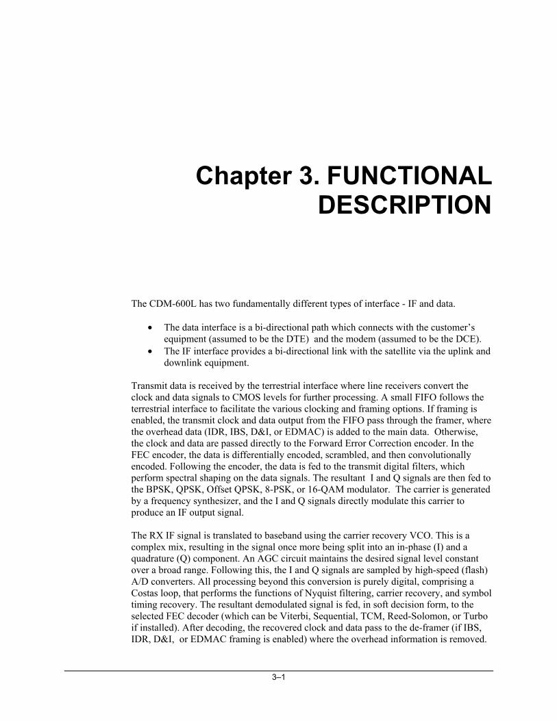
The CDM-600L has two fundamentally different types of interface - IF and data.
• The data interface is a bi-directional path which connects with the customer’s equipment (assumed to be the DTE) and the modem (assumed to be the DCE).
• The IF interface provides a bi-directional link with the satellite via the uplink and downlink equipment.
Transmit data is received by the terrestrial interface where line receivers convert the clock and data signals to CMOS levels for further processing. A small FIFO follows the terrestrial interface to facilitate the various clocking and framing options. If framing is enabled, the transmit clock and data output from the FIFO pass through the framer, where the overhead data (IDR, IBS, D&I, or EDMAC) is added to the main data. Otherwise, the clock and data are passed directly to the Forward Error Correction encoder. In the FEC encoder, the data is differentially encoded, scrambled, and then convolutionally encoded. Following the encoder, the data is fed to the transmit digital filters, which perform spectral shaping on the data signals. The resultant I and Q signals are then fed to the BPSK, QPSK, Offset QPSK, 8-PSK, or 16-QAM modulator. The carrier is generated by a frequency synthesizer, and the I and Q signals directly modulate this carrier to produce an IF output signal. The RX IF signal is translated to baseband using the carrier recovery VCO. This is a complex mix, resulting in the signal once more being split into an in-phase (I) and a quadrature (Q) component. An AGC circuit maintains the desired signal level constant over a broad range. Following this, the I and Q signals are sampled by high-speed (flash) A/D converters. All processing beyond this conversion is purely digital, comprising a Costas loop, that performs the functions of Nyquist filtering, carrier recovery, and symbol timing recovery. The resultant demodulated signal is fed, in soft decision form, to the selected FEC decoder (which can be Viterbi, Sequential, TCM, Reed-Solomon, or Turbo if installed). After decoding, the recovered clock and data pass to the de-framer (if IBS, IDR, D&I, or EDMAC framing is enabled) where the overhead information is removed.
CDM-600L Satellite Modem Revision 2 Functional Description MN/CDM600L.IOM
3–2
Following this, the data passes to the Plesiochronous/Doppler buffer, which has a programmable size, or alternatively bypasses the buffer. From here, the receive clock and data signals are routed to the terrestrial interface, and are passed to the externally connected DTE equipment. Physically the CDM-600L modem is comprised of two main card assemblies.
• The first of these is the baseband framer card, which includes all of the interface circuits, the framer/de-framer, plesiochronous/Doppler buffer, Reed Solomon outer codec, and the main microcontroller.
• The second card is the modem itself, that performs all of signal processing
functions of modulation, demodulation, and Forward Error Correction.
These functions are shown in Figure 3-1.
Figure 3-1. CDM-600L Modem Block Diagram
LVDSINTERFACE
TX FRAMING(IBS, IDR, D&IOR EDMAC) TX REED-
SOLOMONWITH
SCRAMB-LER
SEQENCODER
TX G703 T1/E1DEFRAMER AND
INTERFACE
RS-422, V.35 ORRS-232
INTERFACE
G703 T2/E2INTERFACE
TX LINEDECODING
RX G703 T1/E1DEFRAMER AND
INTERFACE
IBS OREDMACSCRAM-
BLER
MUX
DEMUX
INT CLKDDS
ENC CLKDDS
PL/9076BASEBANDFRAMING
CARD
AS/0424MODEMCARD
I & Q FILTERS
TX IF
RX IF
RX REED-SOLOMONWITH DE-SCRAMB-
LER
OVERHEADINTERFACES
TX AUDIO INTERFACE
IBS OR EDMACDESCRAMBLER
RX DE-FRAMING(IBS, IDR, D&I OR
EDMAC)RX AUDIO INTERFACE
BUFFER
INS CLKDDS
RX LINEENCODING
INSERT
VITERBI& TCMCODEC
TURBO CODECW/ SCRAMBLER
& DESCRAMBLER(OPTIONAL CARD)
SEQDEC-ODER
VIT/SEQ/OM73SCRAMBLERS
VIT/SEQ/OM73DESCRAMBLERS
TXFIR
FIR/PD & I/QRECOVERY
SYM & BITTIMING
RECOVERY
DLF/NCO
MICROPROCESSOR& PROCESSOR FPGA
BIT/SYMDACS
CARRIERDACS
INS CLKDDS
BUFFER CLKDDS
4–1
Chapter 4. PHYSICAL DESCRIPTION
4.1 Introduction
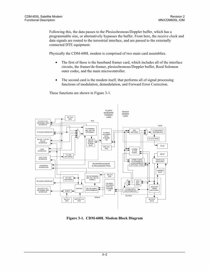
The CDM-600L is constructed as a 1U high rack-mounting chassis, which can be free-standing, if desired. Rack handles at the front facilitate removal from and placement into a rack. Figure 4-1 shows the front panel of the modem.
Figure 4-1. CDM-600L Front Panel
4.2 Front Panel
The CDM-600L front panel features a Vacuum Fluorescent Display (VFD), a keypad, and eight LED indicators. The user enters data via the keypad, and messages are displayed on the VFD. The LEDs indicate, in a summary fashion, the status of the unit. The VFD is an active display showing 2 lines, each of 40 characters. It produces a blue light, the brightness of which can be controlled by the user. It has greatly superior viewing characteristics compared to a Liquid Crystal Display (LCD), and does not suffer problems of viewing angle or contrast.
CDM-600L Satellite Modem Revision 2 Physical Description MN/CDM600L.IOM
4–2
The keypad has six individual keyswitches, mounted directly behind a fully sealed membrane overlay. They have a positive ‘click’ action, which provides the user with tactile feedback. These six switches are identified as [↑], [↓], [→], [←] arrows, ENTER and CLEAR. The functions of these keys are described in the ‘FRONT PANEL OPERATION’ section. There are eight LEDs on the front panel. The behavior of these LEDs is described in the ‘FRONT PANEL OPERATION’ section.
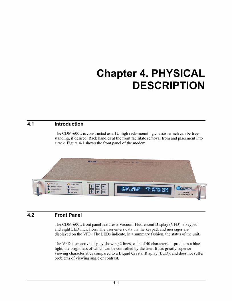
4.3 Rear Panel
Modem with AC Input Power
Modem with DC Input Power
Figure 4-2. CDM-600L Rear Panel
External cables are attached to connectors on the rear panel of the CDM-600L. These comprise:
• IEC line input connector for AC power, or Corcom PS000DD6D for DC power • Rx and Tx IF connectors • Data interface connector • Overhead data connector • Audio connector • External reference connector • External clock connector • IDR alarm connector • Form C alarm connector • Balanced G.703 connector • Unbalanced G.703 Tx/Rx connectors • IDI, DDO connectors • Remote Control connector • Auxiliary Serial connector
CDM-600L Satellite Modem Revision 2 Physical Description MN/CDM600L.IOM
4–3
IEC AC line input connector The IEC line input connector contains the ON/OFF switch for the unit. It is also fitted with two fuses - one each for line and neutral connections (or L1, L2, where appropriate). These are contained within the body of the connector, behind a small plastic flap.
• Use T3.15A, (slow-blow) 20mm fuses.
DC Power input connector The input connector for DC power is Corcom PN PS000DD6D, which mates with Molex connector 03-12-1026 using Molex 18-12-1222 sockets. It is also fitted with two fuses - one each for positive and negative DC input connections. These are contained within the body of the connector, behind a small plastic flap.
• Use T2.0A, (slow-blow) 20mm fuses if modem has no internal BUC power supply
• Use T8.0A, (slow-blow) 20mm fuses if modem has internal BUC power supply.
IMPORTANT
For continued operator safety, always replace the fuses with the correct type and rating.
RX and TX IF connectors (J1 and J2) The TX-IF connector is a 50 Ω Type N female. The RX-IF connector is either a 50Ω Type N female or a 75Ω Type F female. Data interface connector (P3B) The Data connector is a 25-pin ‘D’ type female (DB25-F). This connector conforms to the RS-530 pinout, which allows for connection of different electrical standards, including RS-422, V.35, and RS-232. A shielded 25-pin ‘D’ type provides a very solid solution to EMC problems, unlike the sometimes-used V.35 Winchester connector.
IMPORTANT
It is the responsibility of the user to provide the appropriate cables to connect to this RS-530 connector.
CDM-600L Satellite Modem Revision 2 Physical Description MN/CDM600L.IOM
4–4
Overhead connector (P3A) The Overhead connector is a 25-pin ‘D’ type male (DB25-M). It is used for passing components of INTELSAT specified overhead frame structures. These include 64 kbps RS-422 and 1/16 IBS overhead ESC at RS-232. The IDR backward alarm inputs are found on this connector. Audio connector (P4A) The Audio connector is a 9-pin ‘D’ type female (DB9-F). It is used for the two 32 kbps ADPCM audio inputs and outputs (600Ω transformer coupled, balanced signals). These can be used for both ESC voice circuits in IDR mode, or as the primary data (FAST option). External clock connector (J9) This is a BNC female connector. It is used for operating the buffer with an external station clock. It requires an RS-422 compatible level, so this unbalanced input should have a zero volt offset and a swing of at least ± 2V into the 120Ω termination provided. IDR alarm connector (P5A) The Alarms connector is a 15-pin 'D' type female (DB15-F). Four Form C backward alarm outputs specified by INTELSAT are found on this connector. External Reference connector (J12) This 50Ω BNC female connector provides an external reference input for the Tx and Rx IF synthesizers, and for the internal transmit clock. The load impedance is 60.4Ω, so the VSWR is less than 1.25:1 at either 50Ω or 75Ω. Input level is 0 dBm minimum to +20 dBm maximum at 1, 2, 5, 10, or 20 MHz. When external reference is enabled, the internal 10 MHz reference oscillator is phase locked to the external reference input by a 10Hz bandwidth PLL. If no activity is present at the external reference input, the modem will revert to the internal 10 MHz reference. Form C Traffic alarm connector (P5B) The Alarms connector is a 15-pin 'D' type male (DB15-M). This provides the user with access to the Form-C relay contacts, which indicate the fault status of the unit. These are typically connected to an external fault monitoring system, often found in satellite earth stations. In addition, the receive I and Q demodulator samples are provided on this connector. Connecting these signals to an oscilloscope in X,Y mode will provide the receive signal constellation diagram, which is a useful diagnostic aid. A pin also is provided which can mute the transmit carrier. This requires that the pin be shorted to ground, or a TTL ‘low’, or an RS-232 ‘high’ signal be applied. As an aid to antenna pointing, or for driving step-track equipment, an analog AGC signal is provided on Pin 2 of this connector.
CDM-600L Satellite Modem Revision 2 Physical Description MN/CDM600L.IOM
4–5
Balanced G.703 connector Tx/Rx connector (P7) A 15-pin 'D' type female (DB15-F) for balanced operation at the G.703 data rates of T1 (1.544 Mbps), E1 (2.048 Mbps), or T2 (6.312 Mbps). Unbalanced G.703 Tx/Rx (J10B and J11B) Two female BNC 75Ω connectors for unbalanced operation at the G.703 data rates of E1 (2.048 Mbps), T2 (6.312 Mbps), or E2 (8448 kbps). IDI, DDO connectors (J10A and J11A) Two additional female BNC 75Ω connectors for D&I unbalanced operation at the G.703 data rate of E1 (2.048 Mbps). These are the Insert Data In (IDI) and Drop Data Out (DDO) ports. Another function of these connectors is for auxiliary G.703 data paths operating at 512, 1024, and 2048 kbps. When these rates are selected, the IDI port is the TX terrestrial G.703 input and the DDO port is the RX G.703 output. Remote Control interface connector (P4B) The Remote Control connector is a 9-pin 'D' type male (DB9-M). Access is provided to remote control ports of the modem, both RS-232 and RS-485. Auxiliary Serial connector (P6) This is an additional RS-232 serial port, which is only used when the modem is part of a 1:1 pair. It uses a USB Type B connector.
WARNING
Although this port uses a USB connector, the signals are not USB compatible. DO NOT connect this port to the USB port of a PC, or other computing device.
CDM-600L Satellite Modem Revision 2 Physical Description MN/CDM600L.IOM
4–6
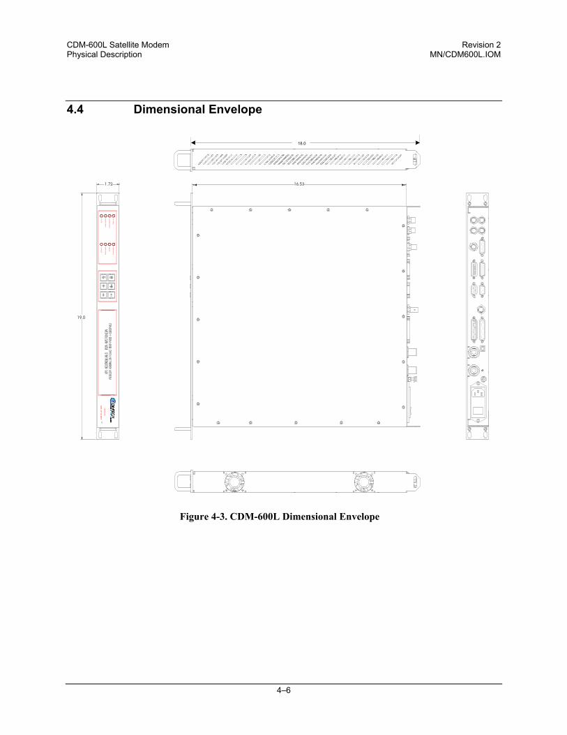
4.4 Dimensional Envelope
Figure 4-3. CDM-600L Dimensional Envelope
CLR
ENT
19.0
1.72 16.53
ONLIN
E
RECEIVE
TRAFFIC
TRANSM
ITTRAFFIC
UNITSTATUS
EDMACMODE
STORED
EVENT
TESTMODE
REMOTE
SATELLITEMODEM
CDM-600
18.0
5–1
Chapter 5. CONNECTOR PINOUTS
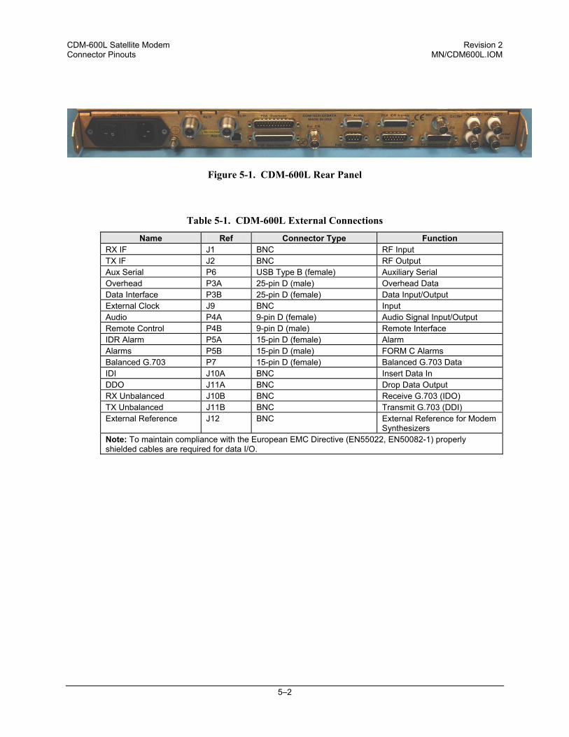
5.1 Connector Overview The rear panel connectors (Figure 5-1) provide all necessary external connections between the modem and other equipment.
CDM-600L Satellite Modem Revision 2 Connector Pinouts MN/CDM600L.IOM
5–2
Figure 5-1. CDM-600L Rear Panel
Table 5-1. CDM-600L External Connections
Name Ref Connector Type Function RX IF J1 BNC RF Input TX IF J2 BNC RF Output Aux Serial P6 USB Type B (female) Auxiliary Serial Overhead P3A 25-pin D (male) Overhead Data Data Interface P3B 25-pin D (female) Data Input/Output External Clock J9 BNC Input Audio P4A 9-pin D (female) Audio Signal Input/Output Remote Control P4B 9-pin D (male) Remote Interface IDR Alarm P5A 15-pin D (female) Alarm Alarms P5B 15-pin D (male) FORM C Alarms Balanced G.703 P7 15-pin D (female) Balanced G.703 Data IDI J10A BNC Insert Data In DDO J11A BNC Drop Data Output RX Unbalanced J10B BNC Receive G.703 (IDO) TX Unbalanced J11B BNC Transmit G.703 (DDI) External Reference J12 BNC External Reference for Modem
Synthesizers Note: To maintain compliance with the European EMC Directive (EN55022, EN50082-1) properly shielded cables are required for data I/O.
CDM-600L Satellite Modem Revision 2 Connector Pinouts MN/CDM600L.IOM
5–3
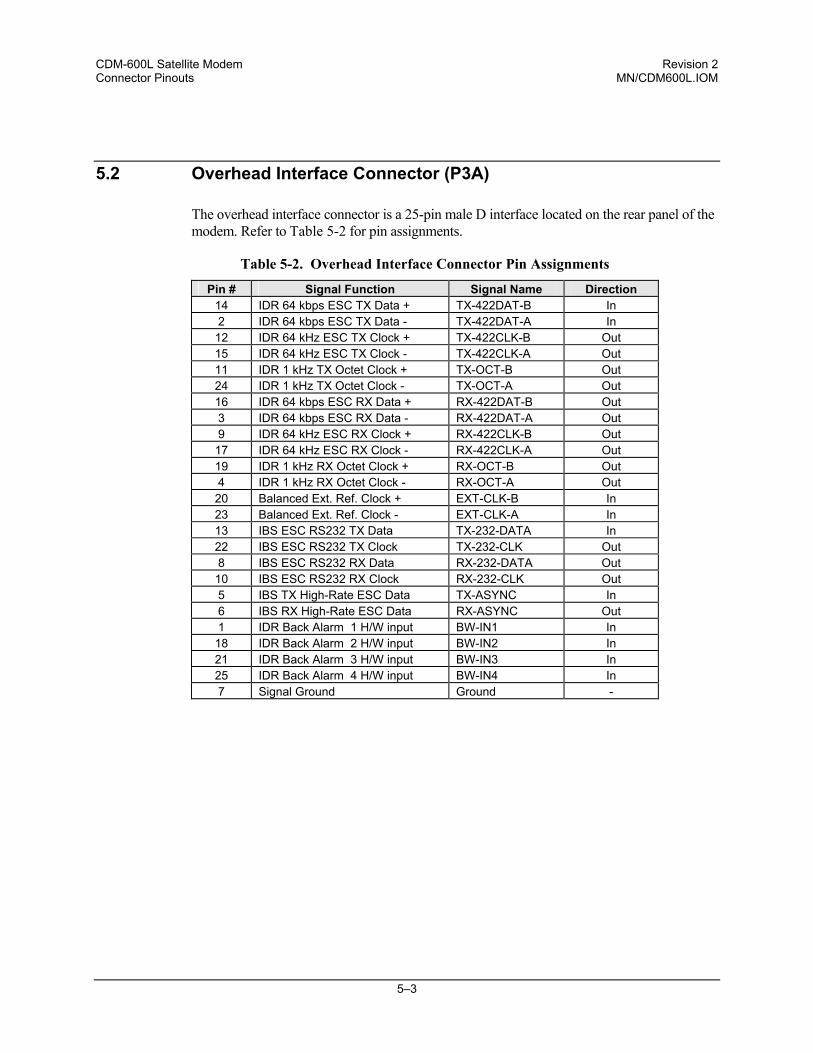
5.2 Overhead Interface Connector (P3A)
The overhead interface connector is a 25-pin male D interface located on the rear panel of the modem. Refer to Table 5-2 for pin assignments.
Table 5-2. Overhead Interface Connector Pin Assignments
Pin # Signal Function Signal Name Direction 14 IDR 64 kbps ESC TX Data + TX-422DAT-B In 2 IDR 64 kbps ESC TX Data - TX-422DAT-A In 12 IDR 64 kHz ESC TX Clock + TX-422CLK-B Out 15 IDR 64 kHz ESC TX Clock - TX-422CLK-A Out 11 IDR 1 kHz TX Octet Clock + TX-OCT-B Out 24 IDR 1 kHz TX Octet Clock - TX-OCT-A Out 16 IDR 64 kbps ESC RX Data + RX-422DAT-B Out 3 IDR 64 kbps ESC RX Data - RX-422DAT-A Out 9 IDR 64 kHz ESC RX Clock + RX-422CLK-B Out 17 IDR 64 kHz ESC RX Clock - RX-422CLK-A Out 19 IDR 1 kHz RX Octet Clock + RX-OCT-B Out 4 IDR 1 kHz RX Octet Clock - RX-OCT-A Out 20 Balanced Ext. Ref. Clock + EXT-CLK-B In 23 Balanced Ext. Ref. Clock - EXT-CLK-A In 13 IBS ESC RS232 TX Data TX-232-DATA In 22 IBS ESC RS232 TX Clock TX-232-CLK Out 8 IBS ESC RS232 RX Data RX-232-DATA Out 10 IBS ESC RS232 RX Clock RX-232-CLK Out 5 IBS TX High-Rate ESC Data TX-ASYNC In 6 IBS RX High-Rate ESC Data RX-ASYNC Out 1 IDR Back Alarm 1 H/W input BW-IN1 In 18 IDR Back Alarm 2 H/W input BW-IN2 In 21 IDR Back Alarm 3 H/W input BW-IN3 In 25 IDR Back Alarm 4 H/W input BW-IN4 In 7 Signal Ground Ground -
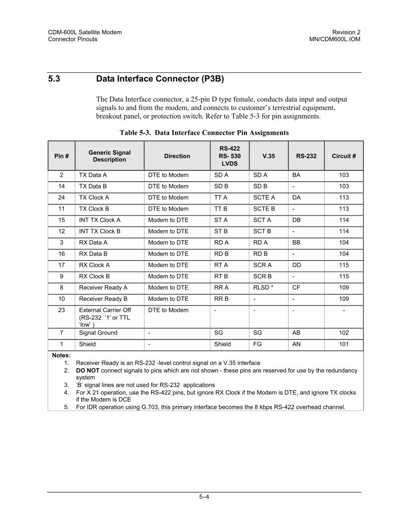
CDM-600L Satellite Modem Revision 2 Connector Pinouts MN/CDM600L.IOM
5–4
5.3 Data Interface Connector (P3B)
The Data Interface connector, a 25-pin D type female, conducts data input and output signals to and from the modem, and connects to customer’s terrestrial equipment, breakout panel, or protection switch. Refer to Table 5-3 for pin assignments.
Table 5-3. Data Interface Connector Pin Assignments
Pin # Generic Signal Description Direction
RS-422 RS- 530 LVDS
V.35 RS-232 Circuit #
2 TX Data A DTE to Modem SD A SD A BA 103
14 TX Data B DTE to Modem SD B SD B - 103
24 TX Clock A DTE to Modem TT A SCTE A DA 113
11 TX Clock B DTE to Modem TT B SCTE B - 113
15 INT TX Clock A Modem to DTE ST A SCT A DB 114
12 INT TX Clock B Modem to DTE ST B SCT B - 114
3 RX Data A Modem to DTE RD A RD A BB 104
16 RX Data B Modem to DTE RD B RD B - 104
17 RX Clock A Modem to DTE RT A SCR A DD 115
9 RX Clock B Modem to DTE RT B SCR B - 115
8 Receiver Ready A Modem to DTE RR A RLSD * CF 109
10 Receiver Ready B Modem to DTE RR B - - 109
23 External Carrier Off (RS-232 ‘1' or TTL ‘low’ )
DTE to Modem - - - -
7 Signal Ground - SG SG AB 102
1 Shield - Shield FG AN 101
Notes: 1. Receiver Ready is an RS-232 -level control signal on a V.35 interface 2. DO NOT connect signals to pins which are not shown - these pins are reserved for use by the redundancy
system 3. ‘B’ signal lines are not used for RS-232 applications 4. For X.21 operation, use the RS-422 pins, but ignore RX Clock if the Modem is DTE, and ignore TX clocks
if the Modem is DCE 5. For IDR operation using G.703, this primary interface becomes the 8 kbps RS-422 overhead channel.
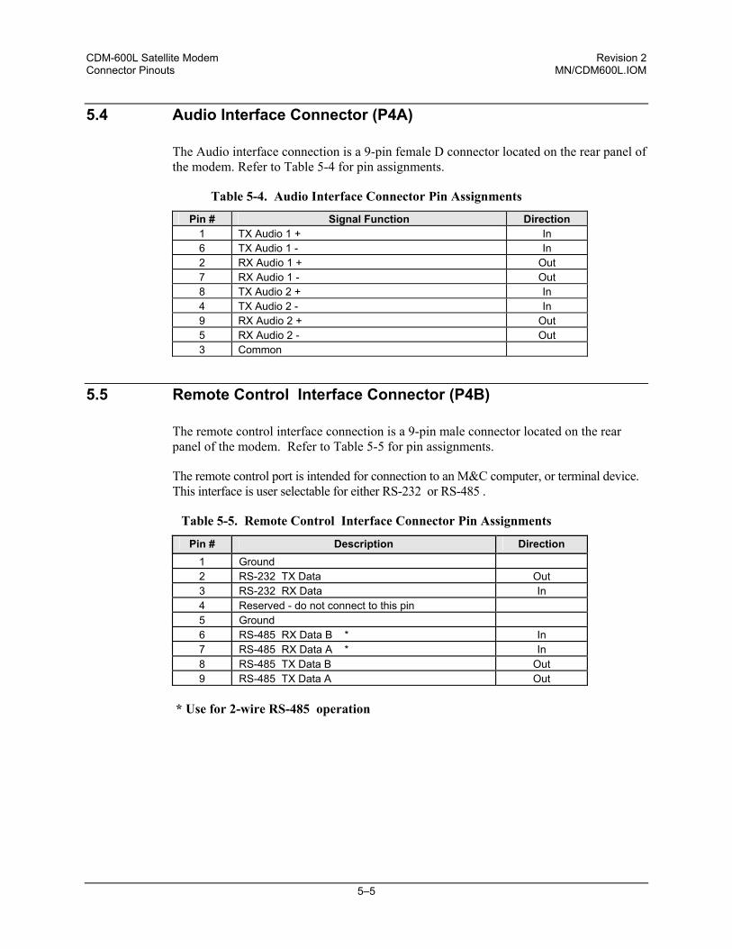
CDM-600L Satellite Modem Revision 2 Connector Pinouts MN/CDM600L.IOM
5–5
5.4 Audio Interface Connector (P4A)
The Audio interface connection is a 9-pin female D connector located on the rear panel of the modem. Refer to Table 5-4 for pin assignments.
Table 5-4. Audio Interface Connector Pin Assignments
Pin # Signal Function Direction 1 TX Audio 1 + In 6 TX Audio 1 - In 2 RX Audio 1 + Out 7 RX Audio 1 - Out 8 TX Audio 2 + In 4 TX Audio 2 - In 9 RX Audio 2 + Out 5 RX Audio 2 - Out 3 Common
5.5 Remote Control Interface Connector (P4B)
The remote control interface connection is a 9-pin male connector located on the rear panel of the modem. Refer to Table 5-5 for pin assignments.
The remote control port is intended for connection to an M&C computer, or terminal device. This interface is user selectable for either RS-232 or RS-485 .
Table 5-5. Remote Control Interface Connector Pin Assignments
Pin # Description Direction 1 Ground 2 RS-232 TX Data Out 3 RS-232 RX Data In 4 Reserved - do not connect to this pin 5 Ground 6 RS-485 RX Data B * In 7 RS-485 RX Data A * In 8 RS-485 TX Data B Out 9 RS-485 TX Data A Out
* Use for 2-wire RS-485 operation
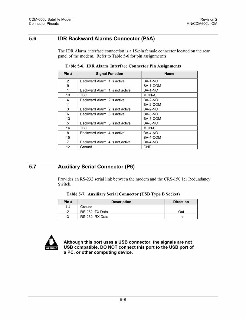
CDM-600L Satellite Modem Revision 2 Connector Pinouts MN/CDM600L.IOM
5–6
5.6 IDR Backward Alarms Connector (P5A)
The IDR Alarm interface connection is a 15-pin female connector located on the rear panel of the modem. Refer to Table 5-6 for pin assignmernts.
Table 5-6. IDR Alarm Interface Connector Pin Assignments
Pin # Signal Function Name
2 9 1
Backward Alarm 1 is active Backward Alarm 1 is not active
BA-1-NO BA-1-COM BA-1-NC
10 TBD MON-A 4
11 3
Backward Alarm 2 is active Backward Alarm 2 is not active
BA-2-NO BA-2-COM BA-2-NC
6 13 5
Backward Alarm 3 is active Backward Alarm 3 is not active
BA-3-NO BA-3-COM BA-3-NC
14 TBD MON-B 8
15 7
Backward Alarm 4 is active Backward Alarm 4 is not active
BA-4-NO BA-4-COM BA-4-NC
12 Ground GND
5.7 Auxiliary Serial Connector (P6)
Provides an RS-232 serial link between the modem and the CRS-150 1:1 Redundancy Switch.
Table 5-7. Auxiliary Serial Connector (USB Type B Socket)
Pin # Description Direction 1,4 Ground 2 RS-232 TX Data Out 3 RS-232 RX Data In
WARNING
Although this port uses a USB connector, the signals are not USB compatible. DO NOT connect this port to the USB port of a PC, or other computing device.
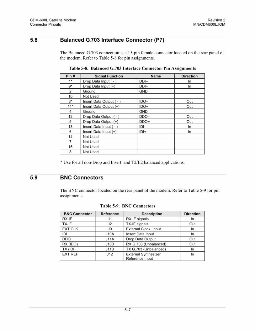
CDM-600L Satellite Modem Revision 2 Connector Pinouts MN/CDM600L.IOM
5–7
5.8 Balanced G.703 Interface Connector (P7)
The Balanced G.703 connection is a 15-pin female connector located on the rear panel of the modem. Refer to Table 5-8 for pin assignments.
Table 5-8. Balanced G.703 Interface Connector Pin Assignments
Pin # Signal Function Name Direction 1* Drop Data Input ( - ) DDI– In 9* Drop Data Input (+) DDI+ In 2 Ground GND
10 Not Used 3* Insert Data Output ( - ) IDO– Out
11* Insert Data Output (+) IDO+ Out 4 Ground GND
12 Drop Data Output ( - ) DDO– Out 5 Drop Data Output (+) DDO+ Out
13 Insert Data Input ( - ) IDI– In 6 Insert Data Input (+) IDI+ In
14 Not Used 7 Not Used
15 Not Used 8 Not Used
* Use for all non-Drop and Insert and T2/E2 balanced applications.
5.9 BNC Connectors
The BNC connector located on the rear panel of the modem. Refer to Table 5-9 for pin assignments.
Table 5-9. BNC Connectors
BNC Connector Reference Description Direction RX-IF J1 RX-IF signals In TX-IF J2 TX-IF signals Out EXT CLK J9 External Clock Input In IDI J10A Insert Data Input In DDO J11A Drop Data Output Out RX (IDO) J10B RX G.703 (Unbalanced) Out TX (IDI) J11B TX G.703 (Unbalanced) In EXT REF J12 External Synthesizer
Reference Input In
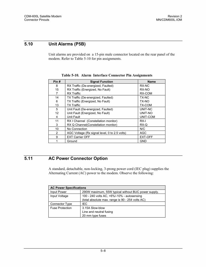
CDM-600L Satellite Modem Revision 2 Connector Pinouts MN/CDM600L.IOM
5–8
5.10 Unit Alarms (P5B)
Unit alarms are provided on a 15-pin male connector located on the rear panel of the modem. Refer to Table 5-10 for pin assignments.
Table 5-10. Alarm Interface Connector Pin Assignments
Pin # Signal Function Name 8
15 7
RX Traffic (De-energized, Faulted) RX Traffic (Energized, No Fault) RX Traffic
RX-NC RX-NO RX-COM
14 6
13
TX Traffic (De-energized, Faulted) TX Traffic (Energized, No Fault) TX Traffic
TX-NC TX-NO TX-COM
5 12 4
Unit Fault (De-energized, Faulted) Unit Fault (Energized, No Fault) Unit Fault
UNIT-NC UNIT-NO UNIT-COM
11 3
RX I Channel (Constellation monitor) RX Q Channel(Constellation monitor)
RX-I RX-Q
10 No Connection N/C 2 AGC Voltage (Rx signal level, 0 to 2.5 volts) AGC 9 EXT Carrier OFF EXT-OFF 1 Ground GND
5.11 AC Power Connector Option
A standard, detachable, non-locking, 3-prong power cord (IEC plug) supplies the Alternating Current (AC) power to the modem. Observe the following:
AC Power Specifications Input Power 290W maximum, 55W typical without BUC power supply. Input Voltage 100 - 240 volts AC, +6%/-10% - autosensing
(total absolute max. range is 90 - 254 volts AC) Connector Type IEC Fuse Protection 3.15A Slow-blow
Line and neutral fusing 20 mm type fuses
CDM-600L Satellite Modem Revision 2 Connector Pinouts MN/CDM600L.IOM
5–9
5.12 DC Power Connector Option
A detachable, locking, 2-prong power cord supplies the Direct Current (DC) power to the modem. Observe the following:
DC Power Specifications Input Power 250W maximum, 55W typical without BUC power supply. Input Voltage 38-60 volts DC Connector Type Molex 03-12-1026 with 08-12-1222 terminals Fuse Protection T3.15A Slow-blow without internal BUC power supply
8.0A Slow-blow with internal BUC power supply Positive and negative fusing 20 mm type fuses
5.13 Ground Connector
A #10-32 stud on the rear panel of the modem is used for connecting a common chassis ground among equipment.
Note: The AC power connector provides the safety ground.

CDM-600L Satellite Modem Revision 2 Connector Pinouts MN/CDM600L.IOM
5–10
NOTES:
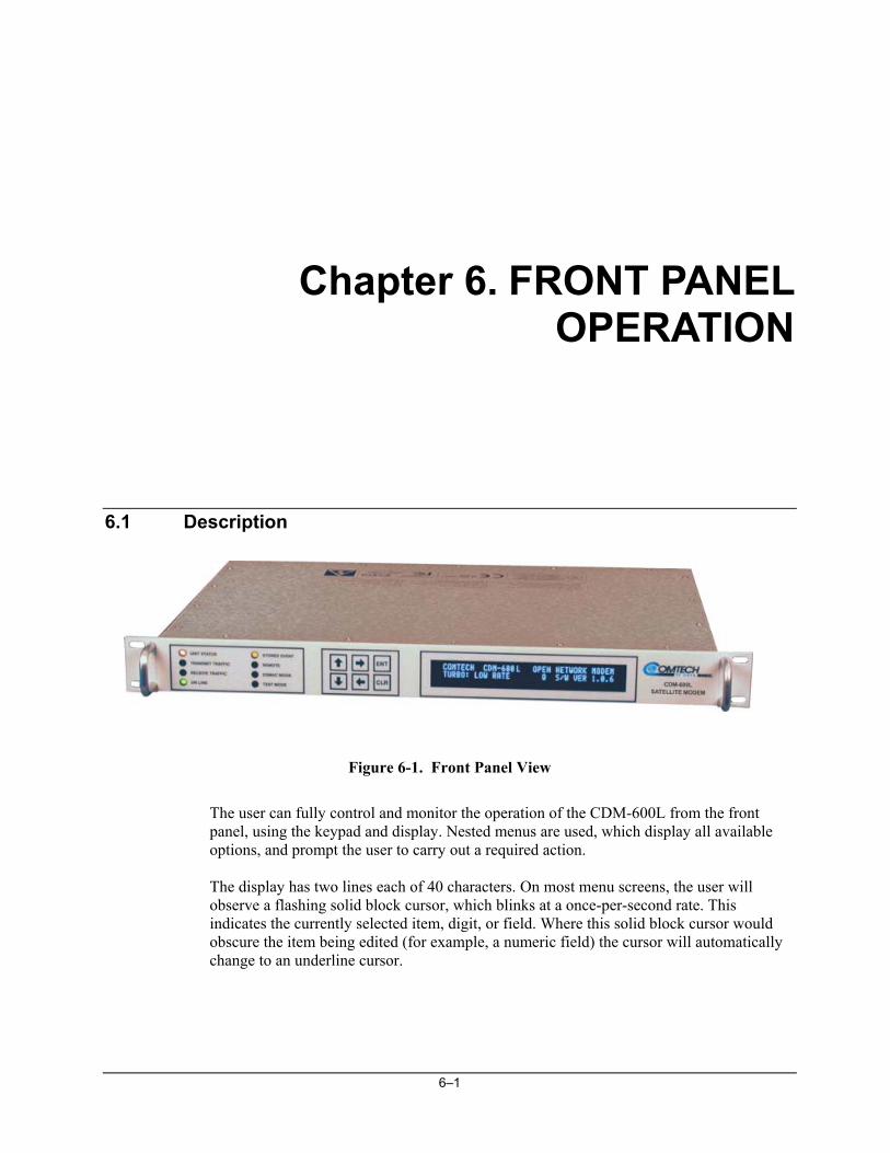
6–1
Chapter 6. FRONT PANEL OPERATION
6.1 Description
Figure 6-1. Front Panel View
The user can fully control and monitor the operation of the CDM-600L from the front panel, using the keypad and display. Nested menus are used, which display all available options, and prompt the user to carry out a required action. The display has two lines each of 40 characters. On most menu screens, the user will observe a flashing solid block cursor, which blinks at a once-per-second rate. This indicates the currently selected item, digit, or field. Where this solid block cursor would obscure the item being edited (for example, a numeric field) the cursor will automatically change to an underline cursor.
CDM-600L Satellite Modem Revision 2 Front Panel Operation MN/CDM600L.IOM
6–2
If the user were to display the same screen for weeks at a time, the display could become ‘burnt’ with this image. To prevent this, the unit has a ‘screen saver’ feature which will activate after 1 hour. The top line of the display will show the Circuit ID (which can be entered by the user) and the bottom line will show the circuit Eb/No value (if the demod is locked) followed by ‘Press any key....’. The message moves from right to left across the screen, then wraps around. Pressing any key will restore the previous screen.
The behavior of the front panel LEDs is described below in Table 6-1.
Table 6-1. Front Panel LED Indicators
LED Color Condition Red A Unit Fault exists (Example: PSU fault) Orange No Unit Faults, but a Traffic Fault exists
Unit Status
Green No Unit Faults, or Traffic Faults Green No Tx Traffic Faults
Flashing
On/Off once per second. The carrier-on delay is active. Refer to ODU, BUC, Config menu for setting countdown seconds remaining. It also is indicated via the Remote Command: TXO?; response: TXO=4, which means, OFF due to BUC carrier-on-delay.
Transmit Traffic
Off A Tx Traffic fault exists OR the Tx Carrier is in OFF state Green No Rx Traffic Faults (demod and Viterbi decoder are locked, everything is OK) Receive
Traffic Off An Rx Traffic fault exists (the demod may still be OK) Green The Unit is On Line, and carrying traffic
On line Off The Unit is Off Line (standby) - forced by externally connected 1:1 or 1:N
redundancy system
Orange There is a Stored Event in the log, which can be viewed from the front panel, or retrieved via the remote control interface Stored Event
Off There are no Stored Events Orange The Unit is in Remote Mode - local monitoring is possible, but no local control
Remote Off The Unit is in Local Mode - remote monitoring is possible, but no remote control
Orange Framing on, EDMAC on, and unit defined as Slave - local monitoring is possible, but no local control EDMAC Mode
Off Either no EDMAC, EDMAC Master, or Transparent mode is selected Orange A Test Mode is selected (Example: IF Loopback) Test Mode Off There is no Test Mode currently selected
IMPORTANT
In general, the Alarm relay state will reflect the state of the Front Panel LEDs. For instance, if the Unit Status LED is red, the Unit Alarm relay will be active, etc. The one exception is the Transmit Traffic relay. This will only be activated if a Transmit Traffic Fault exists – it does not reflect the state of the Tx carrier.
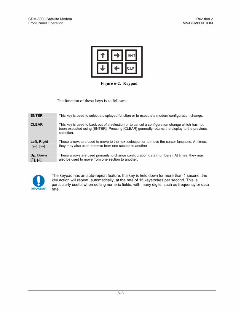
CDM-600L Satellite Modem Revision 2 Front Panel Operation MN/CDM600L.IOM
6–3
Figure 6-2. Keypad
The function of these keys is as follows:
ENTER This key is used to select a displayed function or to execute a modem configuration change.
CLEAR This key is used to back out of a selection or to cancel a configuration change which has not been executed using [ENTER]. Pressing [CLEAR] generally returns the display to the previous selection.
Left, Right [←], [→]
These arrows are used to move to the next selection or to move the cursor functions. At times, they may also used to move from one section to another.
Up, Down [↑], [↓]
These arrows are used primarily to change configuration data (numbers). At times, they may also be used to move from one section to another.
IMPORTANT
The keypad has an auto-repeat feature. If a key is held down for more than 1 second, the key action will repeat, automatically, at the rate of 15 keystrokes per second. This is particularly useful when editing numeric fields, with many digits, such as frequency or data rate.
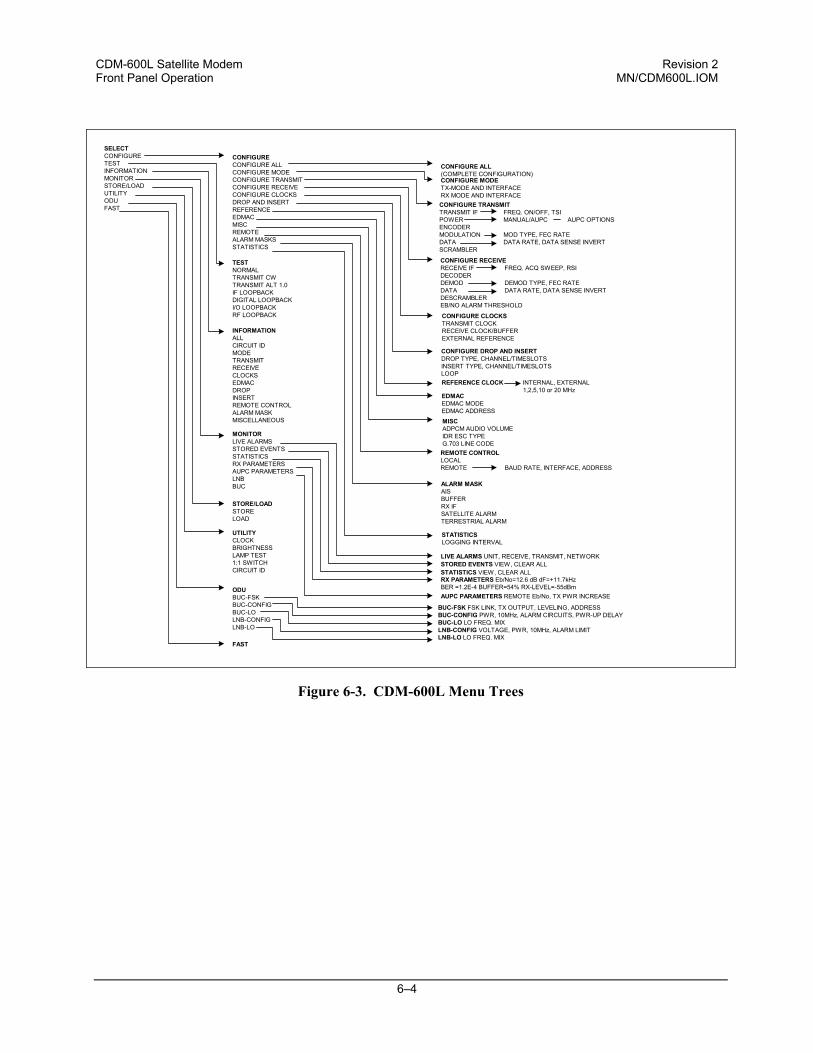
CDM-600L Satellite Modem Revision 2 Front Panel Operation MN/CDM600L.IOM
6–4
SELECTCONFIGURETESTINFORMATIONMONITORSTORE/LOADUTILITYODUFAST
CONFIGURECONFIGURE ALLCONFIGURE MODECONFIGURE TRANSMITCONFIGURE RECEIVECONFIGURE CLOCKSDROP AND INSERTREFERENCEEDMACMISCREMOTEALARM MASKSSTATISTICS
TESTNORMALTRANSMIT CWTRANSMIT ALT 1.0IF LOOPBACKDIGITAL LOOPBACKI/O LOOPBACKRF LOOPBACK
INFORMATIONALLCIRCUIT IDMODETRANSMITRECEIVECLOCKSEDMACDROPINSERTREMOTE CONTROLALARM MASKMISCELLANEOUS
MONITORLIVE ALARMSSTORED EVENTSSTATISTICSRX PARAMETERSAUPC PARAMETERSLNBBUC
STORE/LOADSTORELOAD
UTILITYCLOCKBRIGHTNESSLAMP TEST1:1 SWITCHCIRCUIT ID
ODUBUC-FSKBUC-CONFIGBUC-LOLNB-CONFIGLNB-LO
CONFIGURE ALL(COMPLETE CONFIGURATION)CONFIGURE MODETX-MODE AND INTERFACERX MODE AND INTERFACECONFIGURE TRANSMITTRANSMIT IF FREQ. ON/OFF, TSIPOWER MANUAL/AUPC AUPC OPTIONSENCODERMODULATION MOD TYPE, FEC RATEDATA DATA RATE, DATA SENSE INVERTSCRAMBLER
CONFIGURE RECEIVERECEIVE IF FREQ. ACQ SWEEP, RSIDECODERDEMOD DEMOD TYPE, FEC RATEDATA DATA RATE, DATA SENSE INVERTDESCRAMBLEREB/NO ALARM THRESHOLD
CONFIGURE CLOCKSTRANSMIT CLOCKRECEIVE CLOCK/BUFFEREXTERNAL REFERENCE
CONFIGURE DROP AND INSERTDROP TYPE, CHANNEL/TIMESLOTSINSERT TYPE, CHANNEL/TIMESLOTSLOOPREFERENCE CLOCK INTERNAL, EXTERNAL
1,2,5,10 or 20 MHzEDMACEDMAC MODEEDMAC ADDRESSMISCADPCM AUDIO VOLUMEIDR ESC TYPEG.703 LINE CODE
REMOTE CONTROLLOCALREMOTE BAUD RATE, INTERFACE, ADDRESS
ALARM MASKAISBUFFERRX IFSATELLITE ALARMTERRESTRIAL ALARM
STATISTICSLOGGING INTERVAL
LIVE ALARMS UNIT, RECEIVE, TRANSMIT, NETWORKSTORED EVENTS VIEW, CLEAR ALLSTATISTICS VIEW, CLEAR ALLRX PARAMETERS Eb/No=12.6 dB dF=+11.7kHzBER =1.2E-4 BUFFER=54% RX-LEVEL=-55dBmAUPC PARAMETERS REMOTE Eb/No, TX PWR INCREASE
BUC-FSK FSK LINK, TX OUTPUT, LEVELING, ADDRESSBUC-CONFIG PWR, 10MHz, ALARM CIRCUITS, PWR-UP DELAYBUC-LO LO FREQ. MIXLNB-CONFIG VOLTAGE, PWR, 10MHz, ALARM LIMITLNB-LO LO FREQ. MIX
FAST
Figure 6-3. CDM-600L Menu Trees
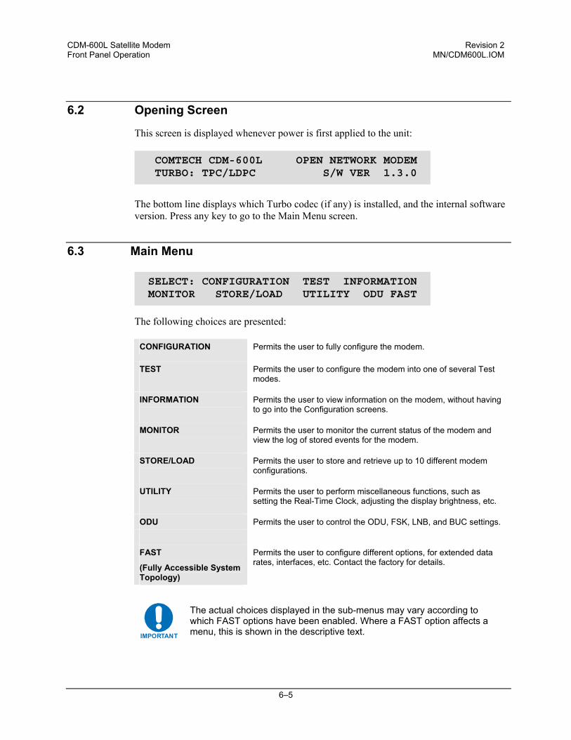
CDM-600L Satellite Modem Revision 2 Front Panel Operation MN/CDM600L.IOM
6–5
6.2 Opening Screen
This screen is displayed whenever power is first applied to the unit:
The bottom line displays which Turbo codec (if any) is installed, and the internal software version. Press any key to go to the Main Menu screen.
6.3 Main Menu
The following choices are presented:
CONFIGURATION Permits the user to fully configure the modem.
TEST
Permits the user to configure the modem into one of several Test modes.
INFORMATION
Permits the user to view information on the modem, without having to go into the Configuration screens.
MONITOR
Permits the user to monitor the current status of the modem and view the log of stored events for the modem.
STORE/LOAD
Permits the user to store and retrieve up to 10 different modem configurations.
UTILITY
Permits the user to perform miscellaneous functions, such as setting the Real-Time Clock, adjusting the display brightness, etc.
ODU Permits the user to control the ODU, FSK, LNB, and BUC settings.
FAST
(Fully Accessible System Topology)
Permits the user to configure different options, for extended data rates, interfaces, etc. Contact the factory for details.
IMPORTANT
The actual choices displayed in the sub-menus may vary according to which FAST options have been enabled. Where a FAST option affects a menu, this is shown in the descriptive text.
COMTECH CDM-600L OPEN NETWORK MODEM TURBO: TPC/LDPC S/W VER 1.3.0
SELECT: CONFIGURATION TEST INFORMATION MONITOR STORE/LOAD UTILITY ODU FAST
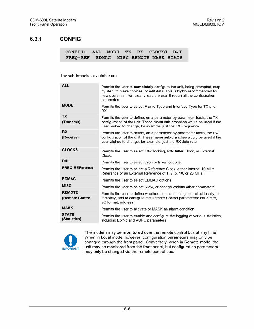
CDM-600L Satellite Modem Revision 2 Front Panel Operation MN/CDM600L.IOM
6–6
6.3.1 CONFIG
The sub-branches available are:
ALL Permits the user to completely configure the unit, being prompted, step by step, to make choices, or edit data. This is highly recommended for new users, as it will clearly lead the user through all the configuration parameters.
MODE Permits the user to select Frame Type and Interface Type for TX and RX.
TX (Transmit)
Permits the user to define, on a parameter-by-parameter basis, the TX configuration of the unit. These menu sub-branches would be used if the user wished to change, for example, just the TX Frequency.
RX (Receive)
Permits the user to define, on a parameter-by-parameter basis, the RX configuration of the unit. These menu sub-branches would be used if the user wished to change, for example, just the RX data rate.
CLOCKS
Permits the user to select TX-Clocking, RX-Buffer/Clock, or External Clock.
D&I Permits the user to select Drop or Insert options. FREQ-REFerence Permits the user to select a Reference Clock, either Internal 10 MHz
Reference or an External Reference of 1, 2, 5, 10, or 20 MHz. EDMAC Permits the user to select EDMAC options. MISC Permits the user to select, view, or change various other parameters. REMOTE (Remote Control)
Permits the user to define whether the unit is being controlled locally, or remotely, and to configure the Remote Control parameters: baud rate, I/O format, address.
MASK Permits the user to activate or MASK an alarm condition. STATS (Statistics)
Permits the user to enable and configure the logging of various statistics, including Eb/No and AUPC parameters
IMPORTANT
The modem may be monitored over the remote control bus at any time. When in Local mode, however, configuration parameters may only be changed through the front panel. Conversely, when in Remote mode, the unit may be monitored from the front panel, but configuration parameters may only be changed via the remote control bus.
CONFIG: ALL MODE TX RX CLOCKS D&I FREQ-REF EDMAC MISC REMOTE MASK STATS
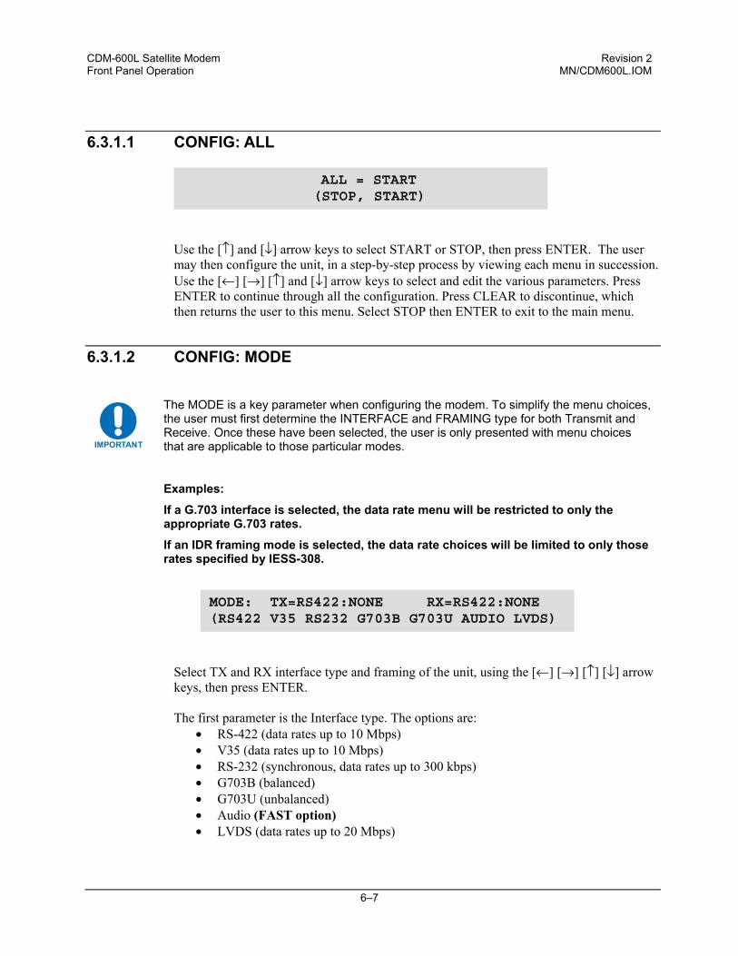
CDM-600L Satellite Modem Revision 2 Front Panel Operation MN/CDM600L.IOM
6–7
6.3.1.1 CONFIG: ALL
Use the [↑] and [↓] arrow keys to select START or STOP, then press ENTER. The user may then configure the unit, in a step-by-step process by viewing each menu in succession. Use the [←] [→] [↑] and [↓] arrow keys to select and edit the various parameters. Press ENTER to continue through all the configuration. Press CLEAR to discontinue, which then returns the user to this menu. Select STOP then ENTER to exit to the main menu.
6.3.1.2 CONFIG: MODE
IMPORTANT
The MODE is a key parameter when configuring the modem. To simplify the menu choices, the user must first determine the INTERFACE and FRAMING type for both Transmit and Receive. Once these have been selected, the user is only presented with menu choices that are applicable to those particular modes.
Examples:
If a G.703 interface is selected, the data rate menu will be restricted to only the appropriate G.703 rates.
If an IDR framing mode is selected, the data rate choices will be limited to only those rates specified by IESS-308.
Select TX and RX interface type and framing of the unit, using the [←] [→] [↑] [↓] arrow keys, then press ENTER. The first parameter is the Interface type. The options are:
• RS-422 (data rates up to 10 Mbps) • V35 (data rates up to 10 Mbps) • RS-232 (synchronous, data rates up to 300 kbps) • G703B (balanced) • G703U (unbalanced) • Audio (FAST option) • LVDS (data rates up to 20 Mbps)
ALL = START (STOP, START)
MODE: TX=RS422:NONE RX=RS422:NONE (RS422 V35 RS232 G703B G703U AUDIO LVDS)
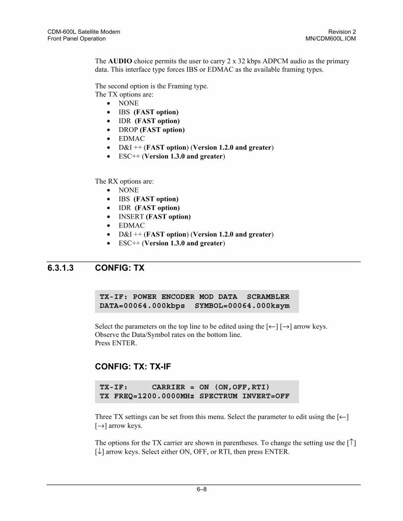
CDM-600L Satellite Modem Revision 2 Front Panel Operation MN/CDM600L.IOM
6–8
The AUDIO choice permits the user to carry 2 x 32 kbps ADPCM audio as the primary data. This interface type forces IBS or EDMAC as the available framing types. The second option is the Framing type. The TX options are:
• NONE • IBS (FAST option) • IDR (FAST option) • DROP (FAST option) • EDMAC • D&I ++ (FAST option) (Version 1.2.0 and greater) • ESC++ (Version 1.3.0 and greater)
The RX options are:
• NONE • IBS (FAST option) • IDR (FAST option) • INSERT (FAST option) • EDMAC • D&I ++ (FAST option) (Version 1.2.0 and greater) • ESC++ (Version 1.3.0 and greater)
6.3.1.3 CONFIG: TX
Select the parameters on the top line to be edited using the [←] [→] arrow keys. Observe the Data/Symbol rates on the bottom line. Press ENTER.
CONFIG: TX: TX-IF
Three TX settings can be set from this menu. Select the parameter to edit using the [←] [→] arrow keys.
The options for the TX carrier are shown in parentheses. To change the setting use the [↑] [↓] arrow keys. Select either ON, OFF, or RTI, then press ENTER.
TX-IF: CARRIER = ON (ON,OFF,RTI)TX FREQ=1200.0000MHz SPECTRUM INVERT=OFF
TX-IF: POWER ENCODER MOD DATA SCRAMBLER DATA=00064.000kbps SYMBOL=00064.000ksym
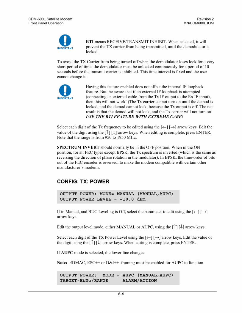
CDM-600L Satellite Modem Revision 2 Front Panel Operation MN/CDM600L.IOM
6–9
IMPORTANT
RTI means RECEIVE/TRANSMIT INHIBIT. When selected, it will prevent the TX carrier from being transmitted, until the demodulator is locked.
To avoid the TX Carrier from being turned off when the demodulator loses lock for a very short period of time, the demodulator must be unlocked continuously for a period of 10 seconds before the transmit carrier is inhibited. This time interval is fixed and the user cannot change it.
IMPORTANT
Having this feature enabled does not affect the internal IF loopback feature. But, be aware that if an external IF loopback is attempted (connecting an external cable from the Tx IF output to the Rx IF input), then this will not work! (The Tx carrier cannot turn on until the demod is locked, and the demod cannot lock, because the Tx output is off. The net result is that the demod will not lock, and the Tx carrier will not turn on. USE THE RTI FEATURE WITH EXTREME CARE!
Select each digit of the Tx frequency to be edited using the [←] [→] arrow keys. Edit the value of the digit using the [↑] [↓] arrow keys. When editing is complete, press ENTER. Note that the range is from 950 to 1950 MHz.
SPECTRUM INVERT should normally be in the OFF position. When in the ON position, for all FEC types except BPSK, the Tx spectrum is inverted (which is the same as reversing the direction of phase rotation in the modulator). In BPSK, the time-order of bits out of the FEC encoder is reversed, to make the modem compatible with certain other manufacturer’s modems.
CONFIG: TX: POWER
If in Manual, and BUC Leveling is Off, select the parameter to edit using the [←] [→]
arrow keys.
Edit the output level mode, either MANUAL or AUPC, using the [↑] [↓] arrow keys.
Select each digit of the TX Power Level using the [←] [→] arrow keys. Edit the value of the digit using the [↑] [↓] arrow keys. When editing is complete, press ENTER. If AUPC mode is selected, the lower line changes: Note: EDMAC, ESC++ or D&I++ framing must be enabled for AUPC to function.
OUTPUT POWER: MODE= MANUAL (MANUAL,AUPC) OUTPUT POWER LEVEL = –10.0 dBm
OUTPUT POWER: MODE = AUPC (MANUAL,AUPC) TARGET-EbNo/RANGE ALARM/ACTION
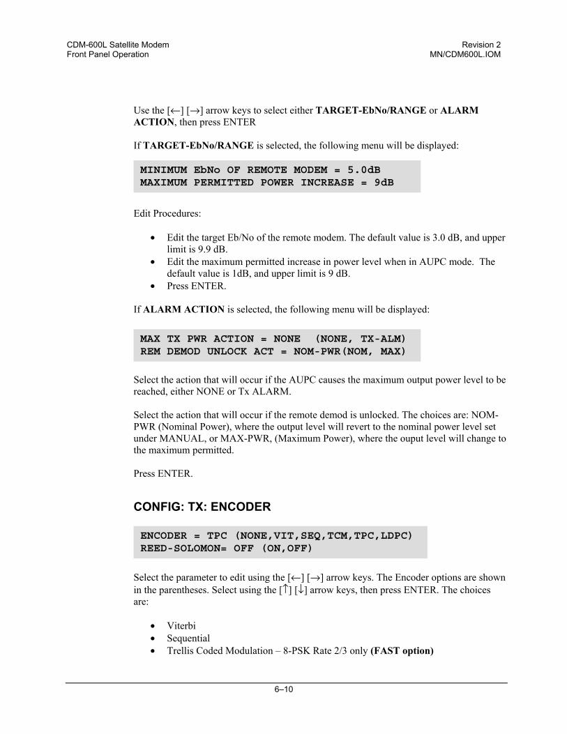
CDM-600L Satellite Modem Revision 2 Front Panel Operation MN/CDM600L.IOM
6–10
Use the [←] [→] arrow keys to select either TARGET-EbNo/RANGE or ALARM ACTION, then press ENTER If TARGET-EbNo/RANGE is selected, the following menu will be displayed:
Edit Procedures:
• Edit the target Eb/No of the remote modem. The default value is 3.0 dB, and upper limit is 9.9 dB.
• Edit the maximum permitted increase in power level when in AUPC mode. The default value is 1dB, and upper limit is 9 dB.
• Press ENTER. If ALARM ACTION is selected, the following menu will be displayed:
Select the action that will occur if the AUPC causes the maximum output power level to be reached, either NONE or Tx ALARM. Select the action that will occur if the remote demod is unlocked. The choices are: NOM-PWR (Nominal Power), where the output level will revert to the nominal power level set under MANUAL, or MAX-PWR, (Maximum Power), where the ouput level will change to the maximum permitted. Press ENTER.
CONFIG: TX: ENCODER
Select the parameter to edit using the [←] [→] arrow keys. The Encoder options are shown in the parentheses. Select using the [↑] [↓] arrow keys, then press ENTER. The choices are:
• Viterbi • Sequential • Trellis Coded Modulation – 8-PSK Rate 2/3 only (FAST option)
ENCODER = TPC (NONE,VIT,SEQ,TCM,TPC,LDPC) REED-SOLOMON= OFF (ON,OFF)
MINIMUM EbNo OF REMOTE MODEM = 5.0dBMAXIMUM PERMITTED POWER INCREASE = 9dB
MAX TX PWR ACTION = NONE (NONE, TX-ALM) REM DEMOD UNLOCK ACT = NOM-PWR(NOM, MAX)
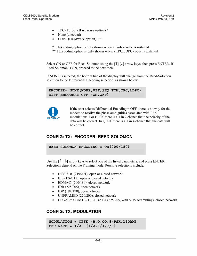
CDM-600L Satellite Modem Revision 2 Front Panel Operation MN/CDM600L.IOM
6–11
• TPC (Turbo) (Hardware option) * • None (uncoded) • LDPC (Hardware option). ** * This coding option is only shown when a Turbo codec is installed. ** This coding option is only shown when a TPC/LDPC codec is installed.
Select ON or OFF for Reed-Solomon using the [↑] [↓] arrow keys, then press ENTER. If Reed-Solomon is ON, proceed to the next menu. If NONE is selected, the bottom line of the display will change from the Reed-Solomon selection to the Differential Encoding selection, as shown below:
IMPORTANT
If the user selects Differential Encoding = OFF, there is no way for the modem to resolve the phase ambiguities associated with PSK modulations. For BPSK there is a 1 in 2 chance that the polarity of the data will be correct. In QPSK there is a 1 in 4 chance that the data will be correct.
CONFIG: TX: ENCODER: REED-SOLOMON
Use the [↑] [↓] arrow keys to select one of the listed parameters, and press ENTER. Selections depend on the Framing mode. Possible selections include:
• IESS-310 (219/201), open or closed network • IBS (126/112), open or closed network • EDMAC (200/180), closed network • IDR (225/205), open network • IDR (194/178), open network • UNFRAMED (220/200), closed network • LEGACY COMTECH EF DATA (225,205, with V.35 scrambling), closed network
CONFIG: TX: MODULATION
REED-SOLOMON ENCODING = ON(200/180)
MODULATION = QPSK (B,Q,OQ,8-PSK,16QAM)FEC RATE = 1/2 (1/2,3/4,7/8)
ENCODER= NONE(NONE,VIT,SEQ,TCM,TPC,LDPC) DIFF-ENCODER= OFF (ON,OFF)
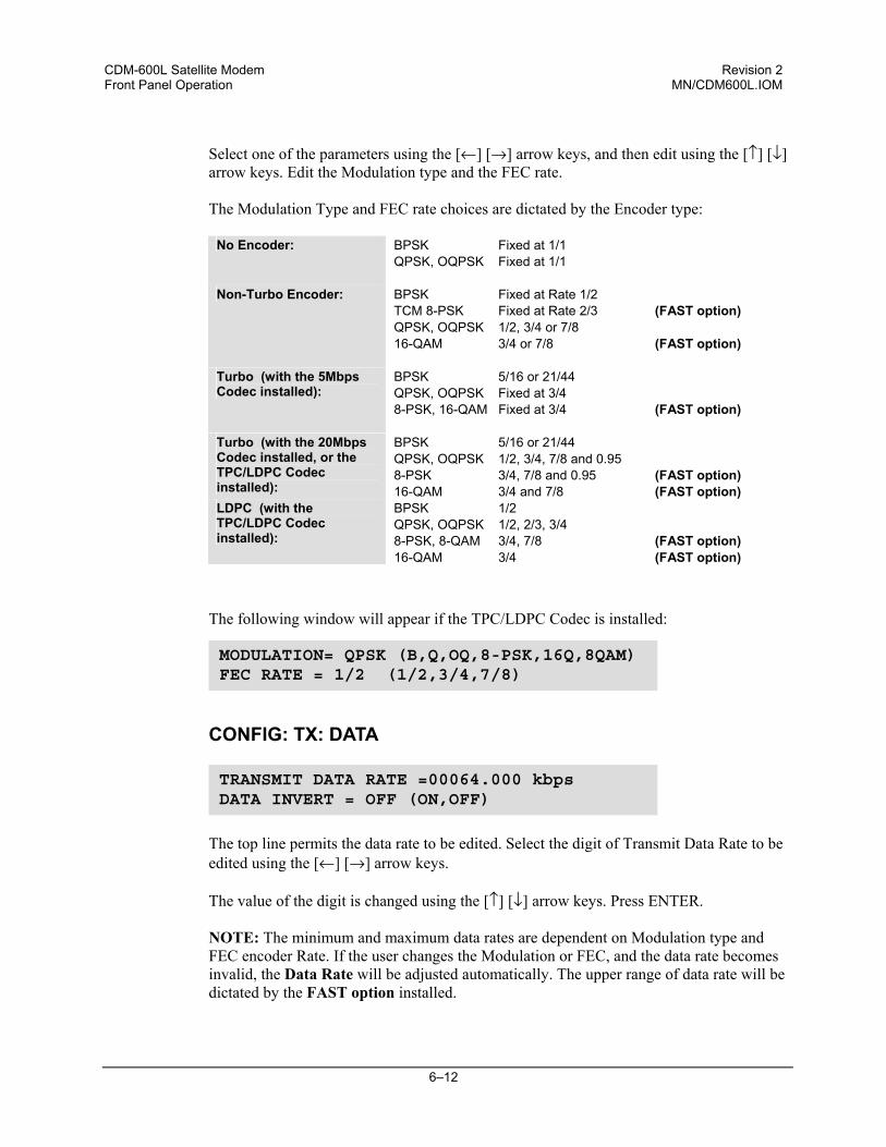
CDM-600L Satellite Modem Revision 2 Front Panel Operation MN/CDM600L.IOM
6–12
Select one of the parameters using the [←] [→] arrow keys, and then edit using the [↑] [↓] arrow keys. Edit the Modulation type and the FEC rate.
The Modulation Type and FEC rate choices are dictated by the Encoder type:
No Encoder: BPSK Fixed at 1/1 QPSK, OQPSK Fixed at 1/1
Non-Turbo Encoder: BPSK Fixed at Rate 1/2 TCM 8-PSK Fixed at Rate 2/3 (FAST option) QPSK, OQPSK 1/2, 3/4 or 7/8 16-QAM 3/4 or 7/8 (FAST option)
Turbo (with the 5Mbps Codec installed):
BPSK 5/16 or 21/44 QPSK, OQPSK Fixed at 3/4 8-PSK, 16-QAM Fixed at 3/4 (FAST option)
Turbo (with the 20Mbps Codec installed, or the TPC/LDPC Codec installed):
BPSK 5/16 or 21/44 QPSK, OQPSK 1/2, 3/4, 7/8 and 0.95 8-PSK 3/4, 7/8 and 0.95 (FAST option) 16-QAM 3/4 and 7/8 (FAST option)
LDPC (with the TPC/LDPC Codec installed):
BPSK 1/2 QPSK, OQPSK 1/2, 2/3, 3/4 8-PSK, 8-QAM 3/4, 7/8 (FAST option) 16-QAM 3/4 (FAST option)
The following window will appear if the TPC/LDPC Codec is installed:
CONFIG: TX: DATA
The top line permits the data rate to be edited. Select the digit of Transmit Data Rate to be edited using the [←] [→] arrow keys.
The value of the digit is changed using the [↑] [↓] arrow keys. Press ENTER.
NOTE: The minimum and maximum data rates are dependent on Modulation type and FEC encoder Rate. If the user changes the Modulation or FEC, and the data rate becomes invalid, the Data Rate will be adjusted automatically. The upper range of data rate will be dictated by the FAST option installed.
TRANSMIT DATA RATE =00064.000 kbpsDATA INVERT = OFF (ON,OFF)
MODULATION= QPSK (B,Q,OQ,8-PSK,16Q,8QAM) FEC RATE = 1/2 (1/2,3/4,7/8)
CDM-600L Satellite Modem Revision 2 Front Panel Operation MN/CDM600L.IOM
6–13
When Drop Framing or the G.703 interface type is used the [↑] [↓] arrow keys will scroll through the available data rates. If in Drop Mode and the data rate is edited to 1920 kbps, a comment is shown to indicate that E1 fixed channel mode will be implemented. When G.703 is used and the Modem is Hardware Revision 2.0 or higher, three auxiliary rates will also be available (512, 1024 and 2048 kbps) indicated by the word AUX appearing to the right of the decimal place. (For example, 00512.AUX kbps). Refer to Section 4.3 IDI/DDO connectors for additional information about how to connect the cables for the AUX data rates. The bottom line permits the user to select the data inversion feature (added for compatibility with certain older equipment). Select either ON or OFF, using the [↑] [↓] arrow keys, then press ENTER.
CONFIG: TX: SCRAMBLER
Select either ON or OFF, using the [↑] [↓] arrow keys, then press ENTER. The choice of scrambler is selected automatically, and will be depend on the exact operating mode. For example, if no framing is being used, the ITU V.35 scrambler (Intelsat variant) will be used. If IBS framing is selected, the IESS-309 scrambler will be used, etc. If Turbo encoding is used, a second scrambler is available: IESS-315 V.35 instead of the TPC scrambler: If LDPC encoding is selected the standard ITU V.35 scrambler will be used.
6.3.1.4 CONFIG: RX
The sub-branches available are:
TX SCRAMBLER = NORMAL (NORMAL,OFF) ENCODER SCRAMBLER
RX-IF DECODER DEMOD DATA DESCRAM EbNo DATA=00064.000kbps SYMBOL=00064.000ksym
TX SCRAMBLER = IESS (NORMAL, IESS, OFF) IESS-315 V.35 SCRAMBLER
CDM-600L Satellite Modem Revision 2 Front Panel Operation MN/CDM600L.IOM
6–14
CONFIG: RX: RX-IF
Edit the Acquisition Sweep Range of the demodulator. The value of the digit is changed using the [↑] [↓] arrow keys. Press ENTER. The value entered determines the amount of frequency uncertainty the demodulator will sweep over in order to find and lock to an incoming carrier. When operating at low bit rates, large values of sweep range (compared to the data rate) will cause excessively long acquisition times. For example: selecting ± 32 kHz with a data rate of 2.4 kbps, BPSK, will result in an average acquisition time of around 3 minutes. Edit the Receive Frequency (RX FREQ) of the demodulator. Select the digit to be edited using the [←] [→] arrow keys. The value of the digit is changed using the [↑] [↓] arrow keys. Press ENTER. Note that the range is from 950 to 1950 MHz.
SPECTRUM INVERT should normally be in the OFF position. When in the ON position,
the receive spectrum is inverted (which is the same as reversing the direction of phase rotation in the demodulator). Note that in BPSK mode, the demodulator will automatically synchronize to either the normal time-ordering of bits FEC codeword pairs, or the inverted ordering used by certain other manufacturers.
CONFIG: RX: DECODER
Select the parameter to edit using the [←] [→] arrow keys.
The Decoder options are shown in the parentheses. Select using the [↑] [↓] arrow keys, then press ENTER. The choices are:
• Viterbi • Sequential • Trellis Coded Modulation - 8-PSK Rate 2/3 only (FAST option) • TPC (Turbo) (Hardware option) * • None (uncoded) • LDPC (Hardware option). ** * This coding option is only shown when a Turbo codec is installed. ** This coding option is only shown when a TPC/LDPC codec is installed.
ACQUISITION SWEEP RANGE = +/- 10 kHzRX FREQ=1200.0000MHz SPECTRUM INVERT=OFF
DECODER= VIT (NONE,VIT,SEQ,TCM,TPC,LDPC) REED-SOLOMON = OFF (ON,OFF)
CDM-600L Satellite Modem Revision 2 Front Panel Operation MN/CDM600L.IOM
6–15
Select ON or OFF for Reed-Solomon using the [↑] [↓] arrow keys, then press ENTER. If Reed-Solomon is ON, proceed to the next menu. If NONE is selected, the bottom line of the display will change from the R-S selection to the Differential Encoding selection, as shown below:
IMPORTANT
If the user selects Differential Decoding = OFF, there is no way for the modem to resolve the phase ambiguities associated with PSK modulations. For BPSK, there is a 1 in 2 chance that the polarity of the data will be correct. In QPSK, there is a 1 in 4 chance that the data will be correct.
CONFIG: RX: DECODER: REED-SOLOMON
Use the [↑] [↓] arrow keys to select one of the listed parameters, and press ENTER. Selections depend on the Framing mode. Possible selections include:
• IESS-310 (219/201), open or closed network • IBS (126/112), open or closed network • EDMAC (200/180), closed network • IDR (225/205), open network • IDR (194/178), open network • UNFRAMED (220/200), closed network • LEGACY COMTECH EF DATA (225,205, with V.35 scrambling), closed network
CONFIG: RX: DEMODULATION
Select one of the parameters using the [←] [→] arrow keys, and then edit using the [↑] [↓] arrow keys. Edit the Modulation type and the FEC rate.
REED-SOLOMON DECODING = ON(200/180)
DEMODULATION=QPSK(B,Q,OQ,8-PSK,16QAM)FEC RATE = 1/2 (1/2,3/4,7/8)
DECODER= NONE(NONE,VIT,SEQ,TCM,TPC,LDPC) DIFF-DECODER= OFF (ON,OFF)
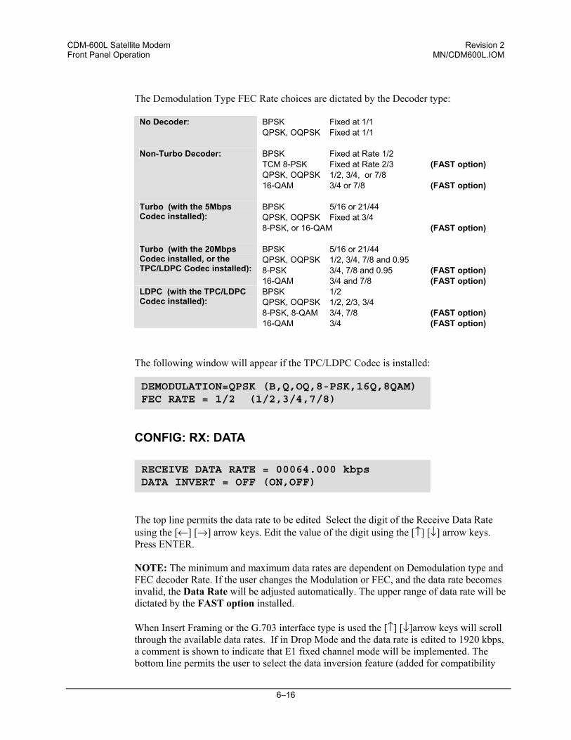
CDM-600L Satellite Modem Revision 2 Front Panel Operation MN/CDM600L.IOM
6–16
The Demodulation Type FEC Rate choices are dictated by the Decoder type:
No Decoder: BPSK Fixed at 1/1
QPSK, OQPSK Fixed at 1/1
Non-Turbo Decoder: BPSK Fixed at Rate 1/2 TCM 8-PSK Fixed at Rate 2/3 (FAST option) QPSK, OQPSK 1/2, 3/4, or 7/8 16-QAM 3/4 or 7/8 (FAST option)
Turbo (with the 5Mbps Codec installed):
BPSK 5/16 or 21/44 QPSK, OQPSK Fixed at 3/4 8-PSK, or 16-QAM (FAST option)
Turbo (with the 20Mbps Codec installed, or the TPC/LDPC Codec installed):
BPSK 5/16 or 21/44 QPSK, OQPSK 1/2, 3/4, 7/8 and 0.95 8-PSK 3/4, 7/8 and 0.95 (FAST option) 16-QAM 3/4 and 7/8 (FAST option)
LDPC (with the TPC/LDPC Codec installed):
BPSK 1/2 QPSK, OQPSK 1/2, 2/3, 3/4 8-PSK, 8-QAM 3/4, 7/8 (FAST option) 16-QAM 3/4 (FAST option)
The following window will appear if the TPC/LDPC Codec is installed:
CONFIG: RX: DATA
The top line permits the data rate to be edited Select the digit of the Receive Data Rate using the [←] [→] arrow keys. Edit the value of the digit using the [↑] [↓] arrow keys. Press ENTER.
NOTE: The minimum and maximum data rates are dependent on Demodulation type and FEC decoder Rate. If the user changes the Modulation or FEC, and the data rate becomes invalid, the Data Rate will be adjusted automatically. The upper range of data rate will be dictated by the FAST option installed. When Insert Framing or the G.703 interface type is used the [↑] [↓]arrow keys will scroll through the available data rates. If in Drop Mode and the data rate is edited to 1920 kbps, a comment is shown to indicate that E1 fixed channel mode will be implemented. The bottom line permits the user to select the data inversion feature (added for compatibility
RECEIVE DATA RATE = 00064.000 kbps DATA INVERT = OFF (ON,OFF)
DEMODULATION=QPSK (B,Q,OQ,8-PSK,16Q,8QAM) FEC RATE = 1/2 (1/2,3/4,7/8)
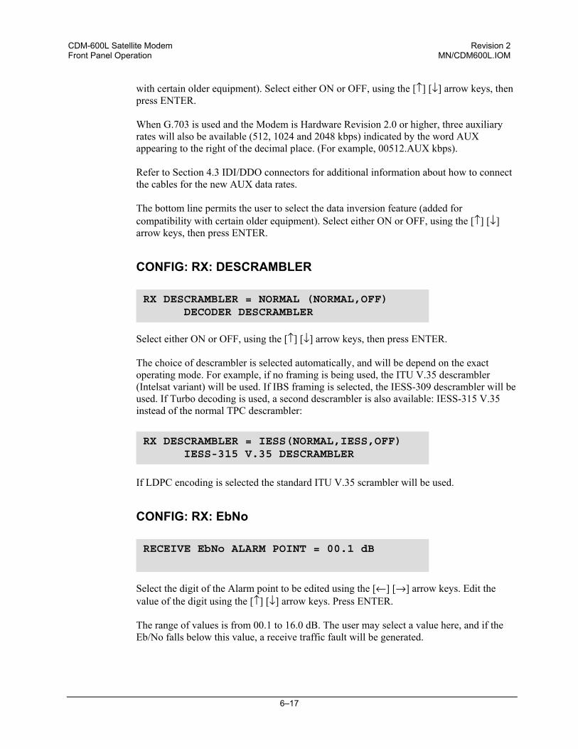
CDM-600L Satellite Modem Revision 2 Front Panel Operation MN/CDM600L.IOM
6–17
with certain older equipment). Select either ON or OFF, using the [↑] [↓] arrow keys, then press ENTER. When G.703 is used and the Modem is Hardware Revision 2.0 or higher, three auxiliary rates will also be available (512, 1024 and 2048 kbps) indicated by the word AUX appearing to the right of the decimal place. (For example, 00512.AUX kbps). Refer to Section 4.3 IDI/DDO connectors for additional information about how to connect the cables for the new AUX data rates. The bottom line permits the user to select the data inversion feature (added for compatibility with certain older equipment). Select either ON or OFF, using the [↑] [↓] arrow keys, then press ENTER.
CONFIG: RX: DESCRAMBLER
Select either ON or OFF, using the [↑] [↓] arrow keys, then press ENTER. The choice of descrambler is selected automatically, and will be depend on the exact operating mode. For example, if no framing is being used, the ITU V.35 descrambler (Intelsat variant) will be used. If IBS framing is selected, the IESS-309 descrambler will be used. If Turbo decoding is used, a second descrambler is also available: IESS-315 V.35 instead of the normal TPC descrambler: If LDPC encoding is selected the standard ITU V.35 scrambler will be used.
CONFIG: RX: EbNo
Select the digit of the Alarm point to be edited using the [←] [→] arrow keys. Edit the value of the digit using the [↑] [↓] arrow keys. Press ENTER. The range of values is from 00.1 to 16.0 dB. The user may select a value here, and if the Eb/No falls below this value, a receive traffic fault will be generated.
RX DESCRAMBLER = NORMAL (NORMAL,OFF) DECODER DESCRAMBLER
RECEIVE EbNo ALARM POINT = 00.1 dB
RX DESCRAMBLER = IESS(NORMAL,IESS,OFF) IESS-315 V.35 DESCRAMBLER
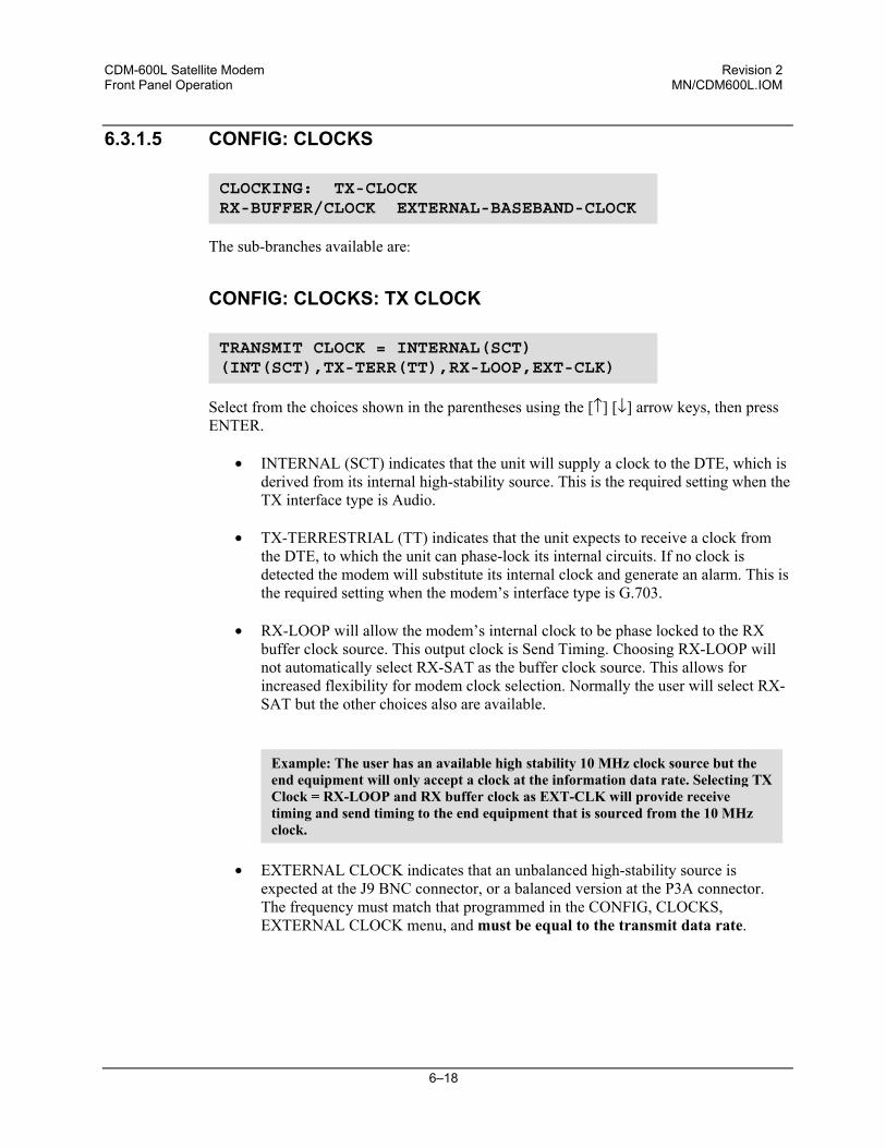
CDM-600L Satellite Modem Revision 2 Front Panel Operation MN/CDM600L.IOM
6–18
6.3.1.5 CONFIG: CLOCKS
The sub-branches available are:
CONFIG: CLOCKS: TX CLOCK
Select from the choices shown in the parentheses using the [↑] [↓] arrow keys, then press ENTER.
• INTERNAL (SCT) indicates that the unit will supply a clock to the DTE, which is derived from its internal high-stability source. This is the required setting when the TX interface type is Audio.
• TX-TERRESTRIAL (TT) indicates that the unit expects to receive a clock from the DTE, to which the unit can phase-lock its internal circuits. If no clock is detected the modem will substitute its internal clock and generate an alarm. This is the required setting when the modem’s interface type is G.703.
• RX-LOOP will allow the modem’s internal clock to be phase locked to the RX buffer clock source. This output clock is Send Timing. Choosing RX-LOOP will not automatically select RX-SAT as the buffer clock source. This allows for increased flexibility for modem clock selection. Normally the user will select RX-SAT but the other choices also are available.
• EXTERNAL CLOCK indicates that an unbalanced high-stability source is
expected at the J9 BNC connector, or a balanced version at the P3A connector. The frequency must match that programmed in the CONFIG, CLOCKS, EXTERNAL CLOCK menu, and must be equal to the transmit data rate.
CLOCKING: TX-CLOCKRX-BUFFER/CLOCK EXTERNAL-BASEBAND-CLOCK
TRANSMIT CLOCK = INTERNAL(SCT)(INT(SCT),TX-TERR(TT),RX-LOOP,EXT-CLK)
Example: The user has an available high stability 10 MHz clock source but the end equipment will only accept a clock at the information data rate. Selecting TXClock = RX-LOOP and RX buffer clock as EXT-CLK will provide receive timing and send timing to the end equipment that is sourced from the 10 MHz clock.
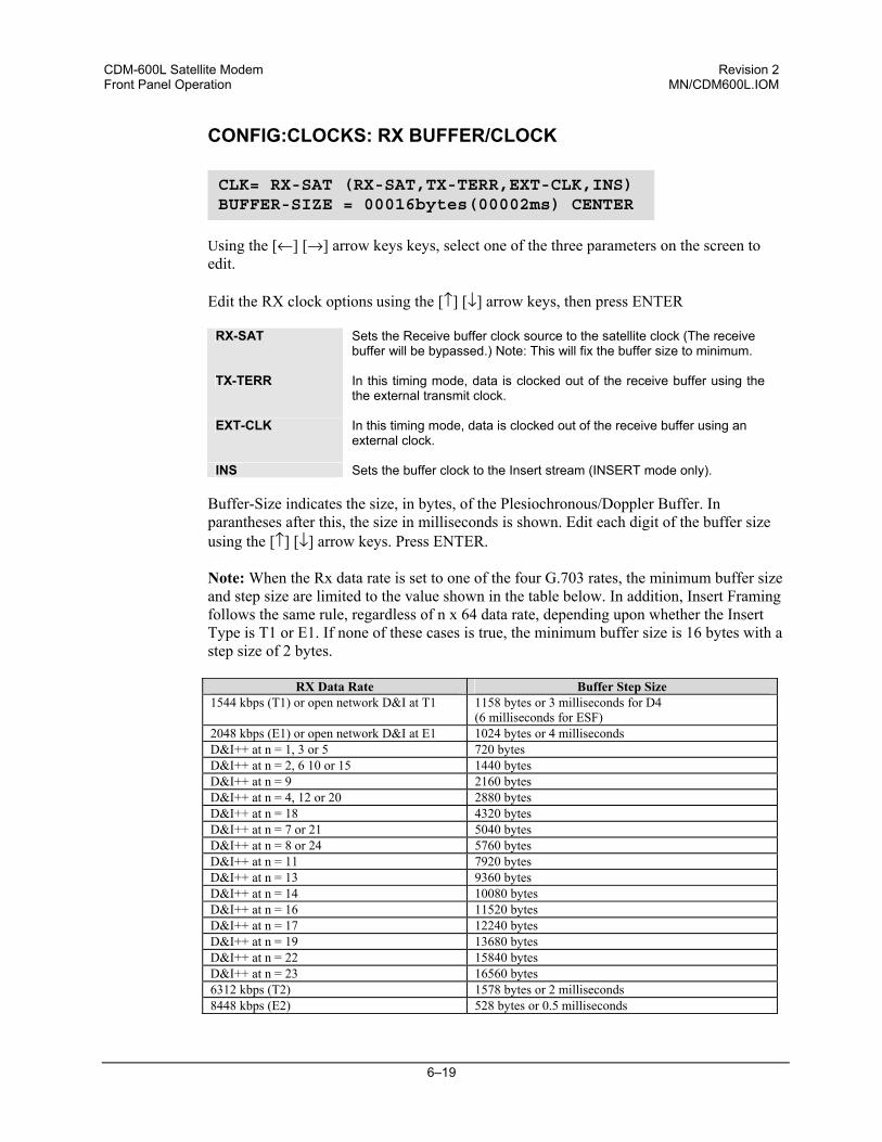
CDM-600L Satellite Modem Revision 2 Front Panel Operation MN/CDM600L.IOM
6–19
CONFIG:CLOCKS: RX BUFFER/CLOCK
Using the [←] [→] arrow keys keys, select one of the three parameters on the screen to edit.
Edit the RX clock options using the [↑] [↓] arrow keys, then press ENTER
RX-SAT Sets the Receive buffer clock source to the satellite clock (The receive
buffer will be bypassed.) Note: This will fix the buffer size to minimum.
TX-TERR In this timing mode, data is clocked out of the receive buffer using the the external transmit clock.
EXT-CLK In this timing mode, data is clocked out of the receive buffer using an external clock.
INS Sets the buffer clock to the Insert stream (INSERT mode only).
Buffer-Size indicates the size, in bytes, of the Plesiochronous/Doppler Buffer. In parantheses after this, the size in milliseconds is shown. Edit each digit of the buffer size using the [↑] [↓] arrow keys. Press ENTER. Note: When the Rx data rate is set to one of the four G.703 rates, the minimum buffer size and step size are limited to the value shown in the table below. In addition, Insert Framing follows the same rule, regardless of n x 64 data rate, depending upon whether the Insert Type is T1 or E1. If none of these cases is true, the minimum buffer size is 16 bytes with a step size of 2 bytes.
RX Data Rate Buffer Step Size 1544 kbps (T1) or open network D&I at T1 1158 bytes or 3 milliseconds for D4
(6 milliseconds for ESF) 2048 kbps (E1) or open network D&I at E1 1024 bytes or 4 milliseconds D&I++ at n = 1, 3 or 5 720 bytes D&I++ at n = 2, 6 10 or 15 1440 bytes D&I++ at n = 9 2160 bytes D&I++ at n = 4, 12 or 20 2880 bytes D&I++ at n = 18 4320 bytes D&I++ at n = 7 or 21 5040 bytes D&I++ at n = 8 or 24 5760 bytes D&I++ at n = 11 7920 bytes D&I++ at n = 13 9360 bytes D&I++ at n = 14 10080 bytes D&I++ at n = 16 11520 bytes D&I++ at n = 17 12240 bytes D&I++ at n = 19 13680 bytes D&I++ at n = 22 15840 bytes D&I++ at n = 23 16560 bytes 6312 kbps (T2) 1578 bytes or 2 milliseconds 8448 kbps (E2) 528 bytes or 0.5 milliseconds
CLK= RX-SAT (RX-SAT,TX-TERR,EXT-CLK,INS) BUFFER-SIZE = 00016bytes(00002ms) CENTER
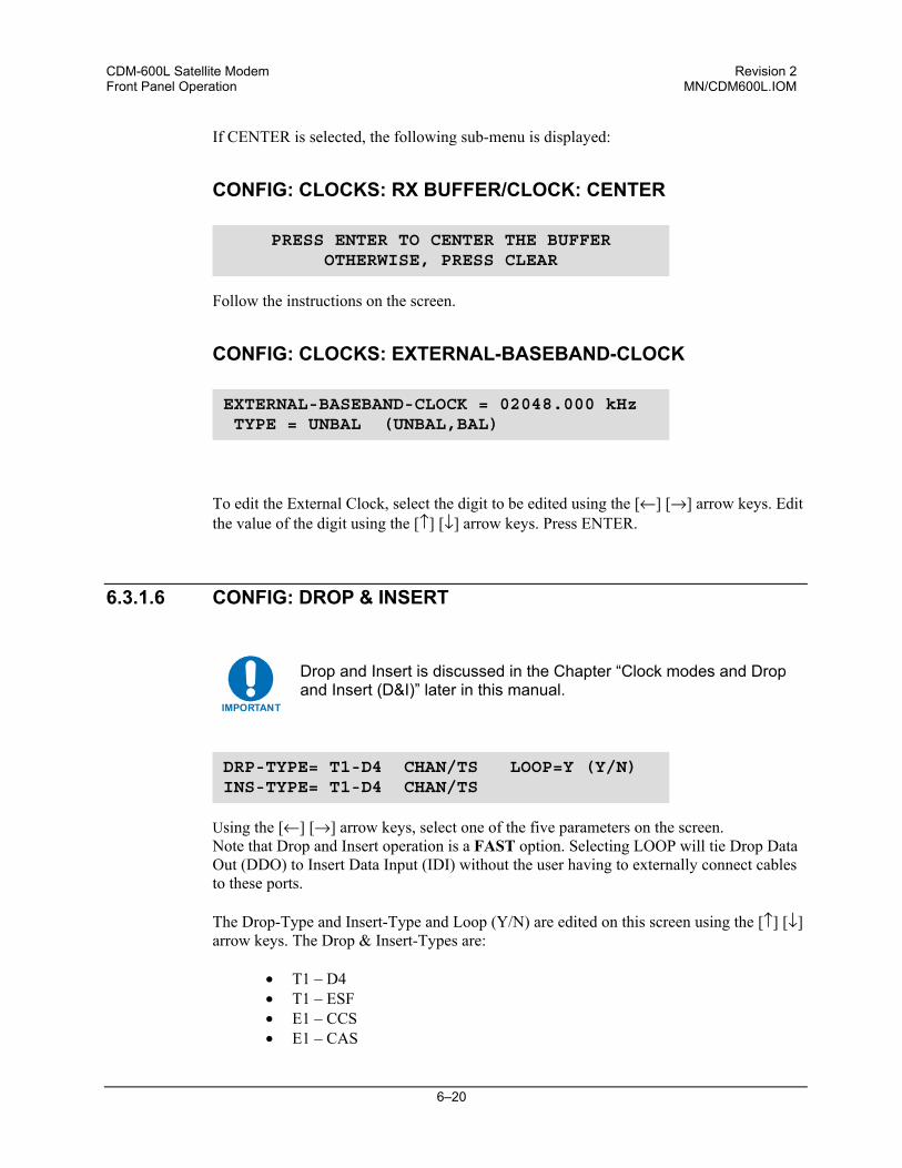
CDM-600L Satellite Modem Revision 2 Front Panel Operation MN/CDM600L.IOM
6–20
If CENTER is selected, the following sub-menu is displayed:
CONFIG: CLOCKS: RX BUFFER/CLOCK: CENTER
Follow the instructions on the screen.
CONFIG: CLOCKS: EXTERNAL-BASEBAND-CLOCK
To edit the External Clock, select the digit to be edited using the [←] [→] arrow keys. Edit the value of the digit using the [↑] [↓] arrow keys. Press ENTER.
6.3.1.6 CONFIG: DROP & INSERT
IMPORTANT
Drop and Insert is discussed in the Chapter “Clock modes and Drop and Insert (D&I)” later in this manual.
Using the [←] [→] arrow keys, select one of the five parameters on the screen. Note that Drop and Insert operation is a FAST option. Selecting LOOP will tie Drop Data
Out (DDO) to Insert Data Input (IDI) without the user having to externally connect cables to these ports.
The Drop-Type and Insert-Type and Loop (Y/N) are edited on this screen using the [↑] [↓] arrow keys. The Drop & Insert-Types are:
• T1 – D4 • T1 – ESF • E1 – CCS • E1 – CAS
PRESS ENTER TO CENTER THE BUFFEROTHERWISE, PRESS CLEAR
EXTERNAL-BASEBAND-CLOCK = 02048.000 kHz TYPE = UNBAL (UNBAL,BAL)
DRP-TYPE= T1-D4 CHAN/TS LOOP=Y (Y/N) INS-TYPE= T1-D4 CHAN/TS
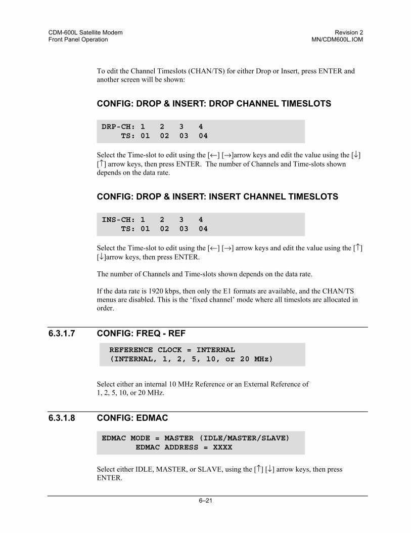
CDM-600L Satellite Modem Revision 2 Front Panel Operation MN/CDM600L.IOM
6–21
To edit the Channel Timeslots (CHAN/TS) for either Drop or Insert, press ENTER and
another screen will be shown:
CONFIG: DROP & INSERT: DROP CHANNEL TIMESLOTS
Select the Time-slot to edit using the [←] [→]arrow keys and edit the value using the [↓]
[↑] arrow keys, then press ENTER. The number of Channels and Time-slots shown depends on the data rate.
CONFIG: DROP & INSERT: INSERT CHANNEL TIMESLOTS
Select the Time-slot to edit using the [←] [→] arrow keys and edit the value using the [↑] [↓]arrow keys, then press ENTER. The number of Channels and Time-slots shown depends on the data rate. If the data rate is 1920 kbps, then only the E1 formats are available, and the CHAN/TS menus are disabled. This is the ‘fixed channel’ mode where all timeslots are allocated in order.
6.3.1.7 CONFIG: FREQ - REF
Select either an internal 10 MHz Reference or an External Reference of 1, 2, 5, 10, or 20 MHz.
6.3.1.8 CONFIG: EDMAC
Select either IDLE, MASTER, or SLAVE, using the [↑] [↓] arrow keys, then press ENTER.
DRP-CH: 1 2 3 4 TS: 01 02 03 04
INS-CH: 1 2 3 4 TS: 01 02 03 04
EDMAC MODE = MASTER (IDLE/MASTER/SLAVE) EDMAC ADDRESS = XXXX
REFERENCE CLOCK = INTERNAL (INTERNAL, 1, 2, 5, 10, or 20 MHz)
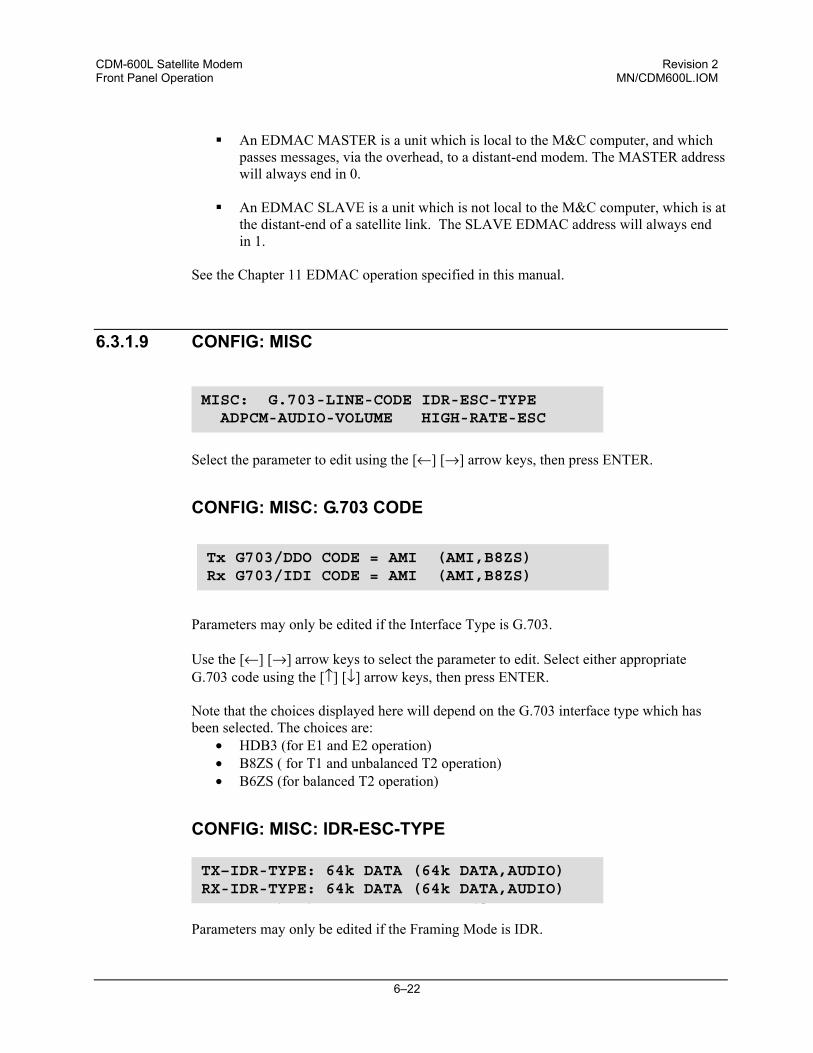
CDM-600L Satellite Modem Revision 2 Front Panel Operation MN/CDM600L.IOM
6–22
An EDMAC MASTER is a unit which is local to the M&C computer, and which
passes messages, via the overhead, to a distant-end modem. The MASTER address will always end in 0.
An EDMAC SLAVE is a unit which is not local to the M&C computer, which is at
the distant-end of a satellite link. The SLAVE EDMAC address will always end in 1.
See the Chapter 11 EDMAC operation specified in this manual.
6.3.1.9 CONFIG: MISC
Select the parameter to edit using the [←] [→] arrow keys, then press ENTER.
CONFIG: MISC: G.703 CODE
Parameters may only be edited if the Interface Type is G.703. Use the [←] [→] arrow keys to select the parameter to edit. Select either appropriate G.703 code using the [↑] [↓] arrow keys, then press ENTER. Note that the choices displayed here will depend on the G.703 interface type which has been selected. The choices are:
• HDB3 (for E1 and E2 operation) • B8ZS ( for T1 and unbalanced T2 operation) • B6ZS (for balanced T2 operation)
CONFIG: MISC: IDR-ESC-TYPE
Parameters may only be edited if the Interface Type is G.703. Parameters may only be edited if the Framing Mode is IDR.
MISC: G.703-LINE-CODE IDR-ESC-TYPE ADPCM-AUDIO-VOLUME HIGH-RATE-ESC
TX–IDR-TYPE: 64k DATA (64k DATA,AUDIO)RX-IDR-TYPE: 64k DATA (64k DATA,AUDIO)
Tx G703/DDO CODE = AMI (AMI,B8ZS)Rx G703/IDI CODE = AMI (AMI,B8ZS)
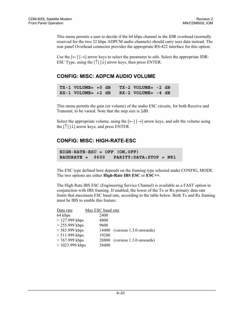
CDM-600L Satellite Modem Revision 2 Front Panel Operation MN/CDM600L.IOM
6–23
This menu permits a user to decide if the 64 kbps channel in the IDR overhead (normally reserved for the two 32 kbps ADPCM audio channels) should carry user data instead. The rear panel Overhead connector provides the appropriate RS-422 interface for this option. Use the [←] [→] arrow keys to select the parameter to edit. Select the appropriate IDR-ESC Type, using the [↑] [↓] arrow keys, then press ENTER.
CONFIG: MISC: ADPCM AUDIO VOLUME
This menu permits the gain (or volume) of the audio ESC circuits, for both Receive and Transmit, to be varied. Note that the step size is 2dB. Select the appropriate volume, using the [←] [→] arrow keys, and edit the volume using the [↑] [↓] arrow keys, and press ENTER.
CONFIG: MISC: HIGH-RATE-ESC
The ESC type defined here depends on the framing type selected under CONFIG, MODE. The two options are either High-Rate IBS ESC or ESC++. The High Rate IBS ESC (Engineering Service Channel) is available as a FAST option in conjunction with IBS framing. If enabled, the lower of the Tx or Rx primary data rate limits that maximum ESC baud rate, according to the table below. Both Tx and Rx framing must be IBS to enable this feature. Data rate Max ESC baud rate 64 kbps 2400 > 127.999 kbps 4800 > 255.999 kbps 9600 > 383.999 kbps 14400 (version 1.3.0 onwards) > 511.999 kbps 19200 > 767.999 kbps 28800 (version 1.3.0 onwards) > 1023.999 kbps 38400
TX-1 VOLUME= +0 dB TX-2 VOLUME= -2 dB RX-1 VOLUME= +2 dB RX-2 VOLUME= -4 dB
HIGH-RATE-ESC = OFF (ON,OFF)BAUDRATE = 9600 PARITY:DATA:STOP = N81
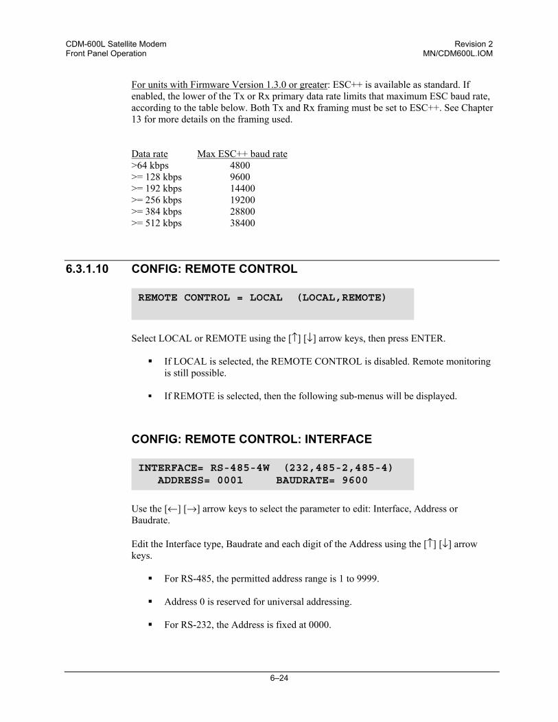
CDM-600L Satellite Modem Revision 2 Front Panel Operation MN/CDM600L.IOM
6–24
For units with Firmware Version 1.3.0 or greater: ESC++ is available as standard. If enabled, the lower of the Tx or Rx primary data rate limits that maximum ESC baud rate, according to the table below. Both Tx and Rx framing must be set to ESC++. See Chapter 13 for more details on the framing used. Data rate Max ESC++ baud rate >64 kbps 4800 >= 128 kbps 9600 >= 192 kbps 14400 >= 256 kbps 19200 >= 384 kbps 28800 >= 512 kbps 38400
6.3.1.10 CONFIG: REMOTE CONTROL
Select LOCAL or REMOTE using the [↑] [↓] arrow keys, then press ENTER.
If LOCAL is selected, the REMOTE CONTROL is disabled. Remote monitoring is still possible.
If REMOTE is selected, then the following sub-menus will be displayed.
CONFIG: REMOTE CONTROL: INTERFACE
Use the [←] [→] arrow keys to select the parameter to edit: Interface, Address or Baudrate.
Edit the Interface type, Baudrate and each digit of the Address using the [↑] [↓] arrow keys.
For RS-485, the permitted address range is 1 to 9999.
Address 0 is reserved for universal addressing.
For RS-232, the Address is fixed at 0000.
REMOTE CONTROL = LOCAL (LOCAL,REMOTE)
INTERFACE= RS-485-4W (232,485-2,485-4) ADDRESS= 0001 BAUDRATE= 9600
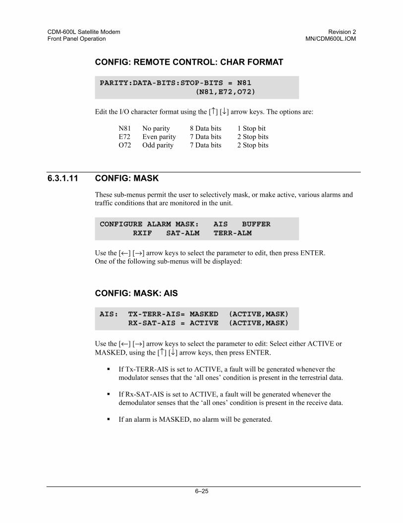
CDM-600L Satellite Modem Revision 2 Front Panel Operation MN/CDM600L.IOM
6–25
CONFIG: REMOTE CONTROL: CHAR FORMAT
Edit the I/O character format using the [↑] [↓] arrow keys. The options are:
N81 No parity 8 Data bits 1 Stop bit E72 Even parity 7 Data bits 2 Stop bits O72 Odd parity 7 Data bits 2 Stop bits
6.3.1.11 CONFIG: MASK
These sub-menus permit the user to selectively mask, or make active, various alarms and traffic conditions that are monitored in the unit.
Use the [←] [→] arrow keys to select the parameter to edit, then press ENTER. One of the following sub-menus will be displayed:
CONFIG: MASK: AIS
Use the [←] [→] arrow keys to select the parameter to edit: Select either ACTIVE or MASKED, using the [↑] [↓] arrow keys, then press ENTER.
If Tx-TERR-AIS is set to ACTIVE, a fault will be generated whenever the
modulator senses that the ‘all ones’ condition is present in the terrestrial data.
If Rx-SAT-AIS is set to ACTIVE, a fault will be generated whenever the demodulator senses that the ‘all ones’ condition is present in the receive data.
If an alarm is MASKED, no alarm will be generated.
PARITY:DATA-BITS:STOP-BITS = N81 (N81,E72,O72)
CONFIGURE ALARM MASK: AIS BUFFER RXIF SAT-ALM TERR-ALM
AIS: TX-TERR-AIS= MASKED (ACTIVE,MASK) RX-SAT-AIS = ACTIVE (ACTIVE,MASK)
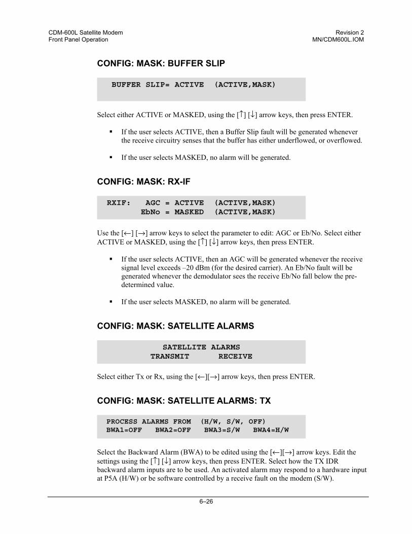
CDM-600L Satellite Modem Revision 2 Front Panel Operation MN/CDM600L.IOM
6–26
CONFIG: MASK: BUFFER SLIP
Select either ACTIVE or MASKED, using the [↑] [↓] arrow keys, then press ENTER.
If the user selects ACTIVE, then a Buffer Slip fault will be generated whenever the receive circuitry senses that the buffer has either underflowed, or overflowed.
If the user selects MASKED, no alarm will be generated.
CONFIG: MASK: RX-IF
Use the [←] [→] arrow keys to select the parameter to edit: AGC or Eb/No. Select either ACTIVE or MASKED, using the [↑] [↓] arrow keys, then press ENTER.
If the user selects ACTIVE, then an AGC will be generated whenever the receive
signal level exceeds –20 dBm (for the desired carrier). An Eb/No fault will be generated whenever the demodulator sees the receive Eb/No fall below the pre-determined value.
If the user selects MASKED, no alarm will be generated.
CONFIG: MASK: SATELLITE ALARMS
Select either Tx or Rx, using the [←][→] arrow keys, then press ENTER.
CONFIG: MASK: SATELLITE ALARMS: TX
Select the Backward Alarm (BWA) to be edited using the [←][→] arrow keys. Edit the settings using the [↑] [↓] arrow keys, then press ENTER. Select how the TX IDR backward alarm inputs are to be used. An activated alarm may respond to a hardware input at P5A (H/W) or be software controlled by a receive fault on the modem (S/W).
BUFFER SLIP= ACTIVE (ACTIVE,MASK)
RXIF: AGC = ACTIVE (ACTIVE,MASK) EbNo = MASKED (ACTIVE,MASK)
SATELLITE ALARMSTRANSMIT RECEIVE
PROCESS ALARMS FROM (H/W, S/W, OFF) BWA1=OFF BWA2=OFF BWA3=S/W BWA4=H/W
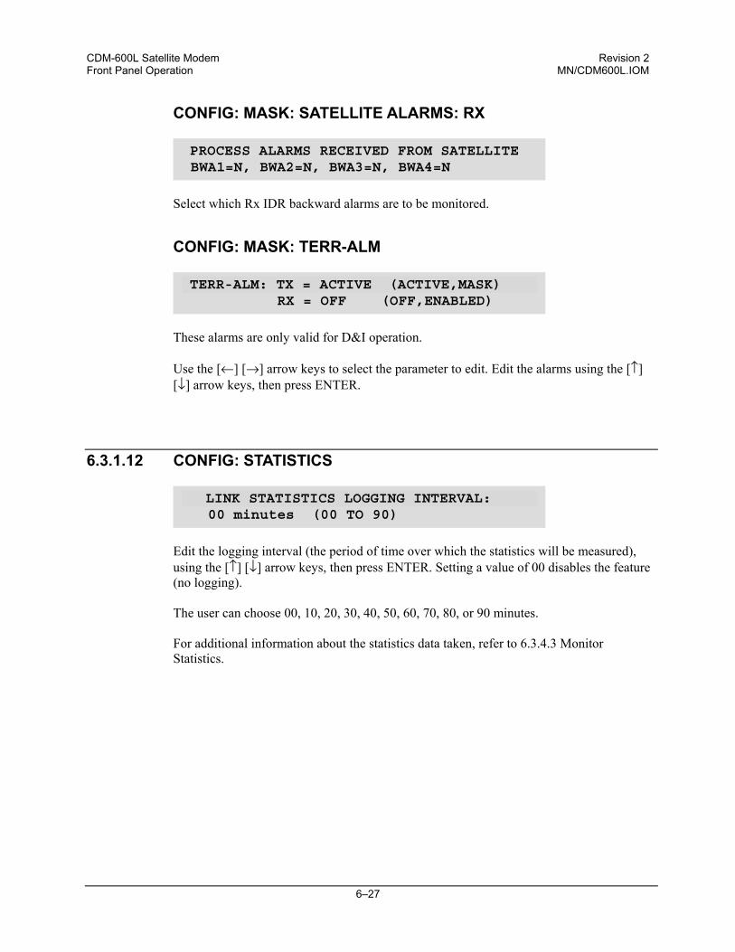
CDM-600L Satellite Modem Revision 2 Front Panel Operation MN/CDM600L.IOM
6–27
CONFIG: MASK: SATELLITE ALARMS: RX
Select which Rx IDR backward alarms are to be monitored.
CONFIG: MASK: TERR-ALM
These alarms are only valid for D&I operation. Use the [←] [→] arrow keys to select the parameter to edit. Edit the alarms using the [↑] [↓] arrow keys, then press ENTER.
6.3.1.12 CONFIG: STATISTICS
Edit the logging interval (the period of time over which the statistics will be measured), using the [↑] [↓] arrow keys, then press ENTER. Setting a value of 00 disables the feature (no logging).
The user can choose 00, 10, 20, 30, 40, 50, 60, 70, 80, or 90 minutes. For additional information about the statistics data taken, refer to 6.3.4.3 Monitor
Statistics.
PROCESS ALARMS RECEIVED FROM SATELLITE BWA1=N, BWA2=N, BWA3=N, BWA4=N
TERR-ALM: TX = ACTIVE (ACTIVE,MASK) RX = OFF (OFF,ENABLED)
LINK STATISTICS LOGGING INTERVAL: 00 minutes (00 TO 90)
CDM-600L Satellite Modem Revision 2 Front Panel Operation MN/CDM600L.IOM
6–28
6.3.2 TEST
Select Test Mode or Normal Operation from the parameters shown in the parentheses using the [↑] [↓] arrow keys, then press ENTER.
This sub-menu permits the user to select the following test modes:
NORM (Normal) This clears any test modes or loopbacks, and places the unit back into an operational state.
TX-CW (Transmit CW) This is a test mode which forces the modulator to transmit a pure carrier (unmodulated).
TX-1,0 (Transmit an alternating 1,0,1,0 pattern) This is a test mode which forces the modulator to transmit a carrier modulated with an alternating 1,0,1,0 pattern, at the currently selected symbol rate. This causes two discrete spectral lines to appear, spaced at ± half the symbol rate, about the carrier frequency. This mode is used to check the carrier suppression of the Modulator.
IF LOOP (IF Loopback) This test mode invokes an internal IF loop. This is a particularly useful feature, as it permits the user to perform a quick diagnostic test without having to disturb external cabling. Furthermore, all of the receive configuration parameters are temporarily changed to match those of the transmit side. When NORMAL is again selected, all of the previous values are restored.
DIG LOOP (Digital Loopback) This test mode invokes a digital loopback, which loops data at the output of the Reed-Solomon encoder on the transmit side, back into the Reed-Solomon decoder on the receive side. This tests all of the interface, transmit baseband circuits, FEC encoder, FEC decoder, and buffer.
I/O LOOP (Inward/Outward loopback) This test mode invokes two distinct loopbacks. The first of these is the inward loop, which takes data being received from the satellite direction, and passes it directly to the modulator. Simultaneously, the outward loop is invoked, whereby data being fed to the transmit data interface is routed directly back out of the receive data interface.
RF LOOP (RF Loopback) This test mode is almost identical to the IF loop mode. All of the receive configuration parameters (except Rx Spectrum Invert) are temporarily changed to match those of the transmit side, however, no internal connection is made. This is useful for performing a satellite loopback. When NORMAL is again selected, all of the previous values are restored.
The IF, Digital, and I/O Loopback modes are illustrated in Figure 6-1.
MODEM TEST MODE = NORMAL (NORM,TX-CW,TX-1/0,IF↓,RF↓,DIG↓,I/O↓)
CDM-600L Satellite Modem Revision 2 Front Panel Operation MN/CDM600L.IOM
6–29
Figure 6-4. Loopback Modes
CDM-600L Satellite Modem Revision 2 Front Panel Operation MN/CDM600L.IOM
6–30
6.3.3 INFORMATION
Select information to view using the [←][→] arrow keys, then press ENTER.
Note: INFO screens display information on the current configuration of the modem without risking inadvertent changes.
6.3.3.1 INFO:ALL
This menu permits the user to view the configuration of the unit, in a step-by-step process by scrolling through each menu in succession. Press ENTER to continue through all the configurations. Note that the user may only view the configurations – no editing is possible. Press CLEAR to discontinue.
6.3.3.2 INFO: ID
This displays the user-defined Circuit ID string (40 characters), which is entered via the UTILITY, ID screen. To return to the previous menu, press ENTER.
6.3.3.3 INFO: MODE
An example of a Mode Information screen is shown above.
INFO: ALL ID FORMAT TX RX CLOCKS EDMAC DROP INSERT REMOTE ALARM-MASK MISC
MODEM CIRCUIT ID:----A TEST MESSAGE TO SHOW CIRCUIT ID---
INFO: MODE: TX = RS422 :NONE RX = RS422 :NONE
ALL = START (STOP, START)
CDM-600L Satellite Modem Revision 2 Front Panel Operation MN/CDM600L.IOM
6–31
6.3.3.4 INFO: TX
A sample display of TX Info is shown. The information displayed here is as follows:
Top Line: TX carrier TX Frequency Power TSI
ON, OFF, or RTI xxxx.xxxx MHz Power Level (dB) TSI = Tx Spectral Inversion, I=Inverted (on), N=Not inverted (off)
Bottom line: Encoder Data Rate Modulation FEC rate Scrambler
FEC type: VITERBI, SEQ, TCM, VIT+RS, SEQ+RS, TCM+RS, TPC, LDPC, NONE:x (x = Differential Encoder setting, indicated as DE–ON or DE–OFF). xxxxx.xxx kbps (an asterix * indicates that the data sense is inverted) BPSK, QPSK, OQPSK, 8-PSK, 8-QAM, 16-QAM 1/2, 2/3, 3/4, 7/8, 0.95, 5/16, 21/44 or 1/1 SCRM, NONE, or IESS (Turbo only)
6.3.3.5 INFO: RX
A sample display of RX Info is shown. The information displayed here is as follows:
Top line: RX Frequency Eb/No Sweep Range RSI
xxxx.xxxx MHz 12 dB (Alarm Point) up to ± 32 kHz RSI = Rx Spectral Inversion, I=Inverted (on), N=Not inverted (off)
Bottom line: Decoder Data Rate Demodulation FEC rate Descrambler
FEC type: VITERBI, SEQ, TCM, VIT+RS, SEQ+RS, TCM+RS, TPC, LDPC, NONE:x (x = Differential Encoder setting, indicated as DE-ON or DE-OFF) xxxxx.xxx kbps (an asterix * indicates that the data sense is inverted) BPSK, QPSK, OQPSK, 8-PSK, 8-QAM, 16-QAM 1/2, 2/3, 3/4, 7/8, 0.95, 5/16, 21/44 or 1/1 SCRM, NONE, or IESS (Turbo only)
TX:ON 1200.0000MHz PWR=-10.0 TSI=NVIT+RS:220/220 00604.000 QPSK 1/2 SCRM
RX:1200.0000MHz 00.1dB +-10 RSI=NVIT+RS:126/112 00604.000 QPSK 1/2 SCRM
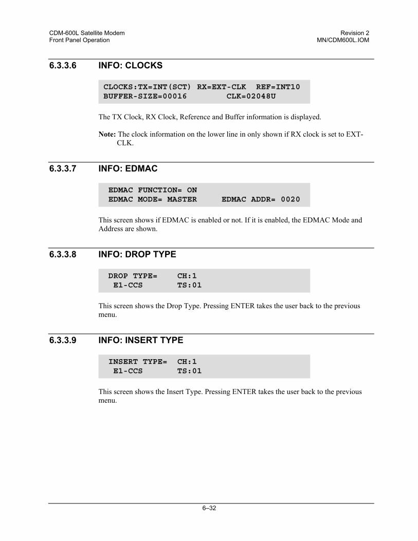
CDM-600L Satellite Modem Revision 2 Front Panel Operation MN/CDM600L.IOM
6–32
6.3.3.6 INFO: CLOCKS
The TX Clock, RX Clock, Reference and Buffer information is displayed. Note: The clock information on the lower line in only shown if RX clock is set to EXT-
CLK.
6.3.3.7 INFO: EDMAC
This screen shows if EDMAC is enabled or not. If it is enabled, the EDMAC Mode and Address are shown.
6.3.3.8 INFO: DROP TYPE
This screen shows the Drop Type. Pressing ENTER takes the user back to the previous menu.
6.3.3.9 INFO: INSERT TYPE
This screen shows the Insert Type. Pressing ENTER takes the user back to the previous menu.
CLOCKS:TX=INT(SCT) RX=EXT-CLK REF=INT10 BUFFER-SIZE=00016 CLK=02048U
EDMAC FUNCTION= ON EDMAC MODE= MASTER EDMAC ADDR= 0020
DROP TYPE= CH:1 E1-CCS TS:01
INSERT TYPE= CH:1 E1-CCS TS:01
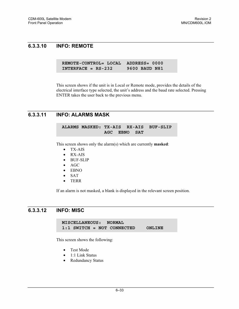
CDM-600L Satellite Modem Revision 2 Front Panel Operation MN/CDM600L.IOM
6–33
6.3.3.10 INFO: REMOTE
This screen shows if the unit is in Local or Remote mode, provides the details of the electrical interface type selected, the unit’s address and the baud rate selected. Pressing ENTER takes the user back to the previous menu.
6.3.3.11 INFO: ALARMS MASK
This screen shows only the alarm(s) which are currently masked:
• TX-AIS • RX-AIS • BUF-SLIP • AGC • EBNO • SAT • TERR
If an alarm is not masked, a blank is displayed in the relevant screen position.
6.3.3.12 INFO: MISC
This screen shows the following:
• Test Mode • 1:1 Link Status • Redundancy Status
REMOTE-CONTROL= LOCAL ADDRESS= 0000 INTERFACE = RS-232 9600 BAUD N81
ALARMS MASKED: TX-AIS RX-AIS BUF-SLIP AGC EBNO SAT
MISCELLANEOUS: NORMAL 1:1 SWITCH = NOT CONNECTED ONLINE
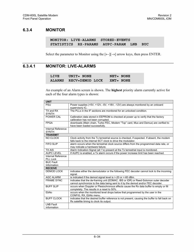
CDM-600L Satellite Modem Revision 2 Front Panel Operation MN/CDM600L.IOM
6–34
6.3.4 MONITOR
Select the parameter to Monitor using the [←][→] arrow keys, then press ENTER.
6.3.4.1 MONITOR: LIVE-ALARMS
An example of an Alarm screen is shown. The highest priority alarm currently active for each of the four alarm types is shown: UNIT PSU
Power supplies (+5V, +12V, -5V, +18V, -12V) are always monitored by an onboard supervisory IC.
TX and RX SYNTH
The PLLs in the IF sections are monitored for an unlocked condition.
POWER CAL Calibration data stored in EEPROM is checked at power up to verify that the factory calibration has not been corrupted.
FPGA downloads (Main chain, Turbo FEC, Modem “Top” card, Mux and Demux) are verified to have been loaded successfully.
Internal Reference SYNTH
TRANSMIT NO CLOCK Clock activity from the Tx terrestrial source is checked, if expected. If absent, the modem
falls back to the internal SCT clock to drive the modulator. FIFO SLIP alarm occurs when the terrestrial clock source differs from the programmed data rate, or
may indicate a hardware failure. TX AIS Alarm Indication Signal (all 1’s) present at the Tx terrestrial input is monitored. AUPC LEVEL If AUPC is enabled, a Tx alarm occurs if the power increase limit has been reached. Internal Reference PLL Lock
BUC Fault Information
RECEIVE DEMOD LOCK indicates either the demodulator or the following FEC decoder cannot lock to the incoming
signal. AGC ALARM is indicated if the demod signal level is >-20 or <-60 dBm. FRAME SYNC indicates that the de-framing unit (EDMAC, IBS or IDR) or Reed-Solomon outer decoder
cannot synchronize to the data being sent to it by the demod and/or FEC decoder. BUFF SLIP occurs when Doppler or Plesiochronous effects cause the Rx data buffer to empty or fill
completely. The results in a reset to 50%. EbNo occurs when the monitored level drops below that programmed by the user in the
CONFIG, RX, EbNo menu. BUFF CLOCK indicates that the desired buffer reference is not present, causing the buffer to fall back on
Rx satellite timing to clock its output. LNB Fault Information
MONITOR: LIVE-ALARMS STORED-EVENTS STATISTICS RX-PARAMS AUPC-PARAM LNB BUC
LIVE UNIT= NONE NET= NONE ALARMS RECV=DEMOD LOCK XMT= NONE
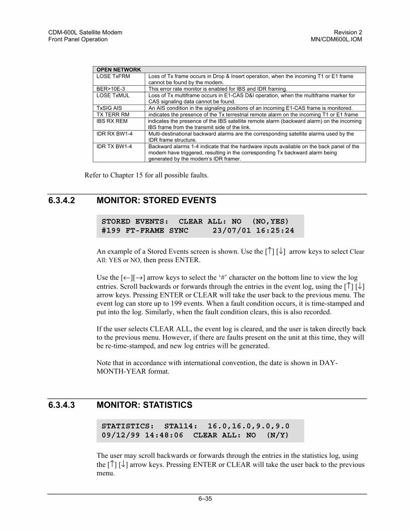
CDM-600L Satellite Modem Revision 2 Front Panel Operation MN/CDM600L.IOM
6–35
OPEN NETWORK LOSE TxFRM Loss of Tx frame occurs in Drop & Insert operation, when the incoming T1 or E1 frame
cannot be found by the modem. BER>10E-3 This error rate monitor is enabled for IBS and IDR framing. LOSE TxMUL Loss of Tx multiframe occurs in E1-CAS D&I operation, when the multiframe marker for
CAS signaling data cannot be found. TxSIG AIS An AIS condition in the signaling positions of an incoming E1-CAS frame is monitored. TX TERR RM indicates the presence of the Tx terrestrial remote alarm on the incoming T1 or E1 frame IBS RX REM indicates the presence of the IBS satellite remote alarm (backward alarm) on the incoming
IBS frame from the transmit side of the link. IDR RX BW1-4 Multi-destinational backward alarms are the corresponding satellite alarms used by the
IDR frame structure. IDR TX BW1-4 Backward alarms 1-4 indicate that the hardware inputs available on the back panel of the
modem have triggered, resulting in the corresponding Tx backward alarm being generated by the modem’s IDR framer.
Refer to Chapter 15 for all possible faults.
6.3.4.2 MONITOR: STORED EVENTS
An example of a Stored Events screen is shown. Use the [↑] [↓] arrow keys to select Clear All: YES or NO, then press ENTER. Use the [←][→] arrow keys to select the ‘#’ character on the bottom line to view the log entries. Scroll backwards or forwards through the entries in the event log, using the [↑] [↓] arrow keys. Pressing ENTER or CLEAR will take the user back to the previous menu. The event log can store up to 199 events. When a fault condition occurs, it is time-stamped and put into the log. Similarly, when the fault condition clears, this is also recorded.
If the user selects CLEAR ALL, the event log is cleared, and the user is taken directly back to the previous menu. However, if there are faults present on the unit at this time, they will be re-time-stamped, and new log entries will be generated.
Note that in accordance with international convention, the date is shown in DAY-MONTH-YEAR format.
6.3.4.3 MONITOR: STATISTICS
The user may scroll backwards or forwards through the entries in the statistics log, using the [↑] [↓] arrow keys. Pressing ENTER or CLEAR will take the user back to the previous menu.
STORED EVENTS: CLEAR ALL: NO (NO,YES) #199 FT-FRAME SYNC 23/07/01 16:25:24
STATISTICS: STA114: 16.0,16.0,9.0,9.0 09/12/99 14:48:06 CLEAR ALL: NO (N/Y)
CDM-600L Satellite Modem Revision 2 Front Panel Operation MN/CDM600L.IOM
6–36
The top line displays the log entry number and event log.The bottom line of the display indicates the time and date of the entry shown in DAY-MONTH-YEAR format. The display shows the statistics data that has been measured and recorded. The statistics logs can store up to 199 log entries. (To enable statistic logging, see Section 6.3.1.12.) The meaning and format of the numbers is as follows:
• The user defines a measurement interval (see CONFIG, STATS) and during this interval, Eb/No and Transmit Power Level Increase (TPLI) are observed, at a 1 second rate.
• At the end of this period, the average Eb/No is calculated and recorded, and the minimum value seen in the interval.
• Similarly, the average TPLI is calculated, along with the highest value seen in the interval.
IMPORTANT
If the demod has lost lock during the measurement interval, the minimum Eb/No will show ‘LOSS’ rather than indicate a value. However, the average value (while the demod was locked) will still be calculated and shown. If, on the other hand, the demodulator has been unlocked for the entire measurement interval, the average Eb/No will also show ‘LOSS’. (The display will show ‘LOSS,LOSS’.)
• If the measured values are ≥ 16.0 dB, the display will show 16.0 dB.
• If AUPC is not enabled, the values of maximum and average TPLI will both show
‘0.0'.
Examples:
08.0,13.5,2.5,1.8 means: Minimum Eb/No observed in the measurement interval = 8.0 dB Average Eb/No observed in the measurement interval = 13.5 dB Maximum TPLI observed in the measurement interval = 2.5 dB Average TPLI observed in the measurement interval = 1.8 dB
LOSS,04.5,0.0,0.0 means: There was a loss of demod lock during the measurement interval Average Eb/No observed in the measurement interval = 4.5 dB Maximum TPLI observed in the measurement interval = 0 dB Average TPLI observed in the measurement interval = 0 dB (Which indicates no AUPC activity, or that AUPC is disabled.)
Use the [←] or [→ ] arrow keys to select the CLEAR ALL option. Select Yes or No using the [↑ ] or [↓] arrow keys and press ENTER to implement, or CLEAR.
CDM-600L Satellite Modem Revision 2 Front Panel Operation MN/CDM600L.IOM
6–37
6.3.4.4 MONITOR: RX PARAMETERS
If the demodulator is locked, this screen shows the following:
Eb/No This shows the value of Eb/No calculated by the demodulator. The value referred to here is the energy per information bit (Ebi), divided by the noise spectral density (No).
∆F The frequency offset of the received carrier, in kHz, with a displayed resolution of 100 Hz.
BER This is an estimate of the corrected BER.
BUFFER (Buffer fill state) This shows the fill state (in percent), of the receive Buffer. After a reset, it will read 50. A value <50 indicates that the buffer is emptying, and >50 indicates that it is filling.
RX-LEVEL A dBm reading indicating the signal level of the desired receive carrier.
6.3.4.5 MONITOR: AUPC-PARAMS
The top line displays the value of Remote Eb/No of the demodulator at the distant end of the satellite link. The Remote Eb/No will display UNLOCK if the remote DEMOD is unlocked. The bottom line shows how much the AUPC system has increased the output power. If AUPC is not enabled, the value of TX POWER INCREASE will show as 0.0 dB.
RX=PARAMETERS: EbNo=11.4dB ∆F=+11.7kHz BER=0.0E-9 BUFFER=51% RX-LEVEL=-43dBm
AUPC-PARAMS: REMOTE EbNo=6.8dB TRANSMIT POWER INCREASE=1.2dB
CDM-600L Satellite Modem Revision 2 Front Panel Operation MN/CDM600L.IOM
6–38
6.3.4.6 MONITOR: LNB
The monitor display shows the measured LNB current load and LNB voltage at the receive IF connector.
6.3.4.7 MONITOR:BUC
CURRENT If a BUC supply is installed, displays measured BUC load current.
VOLT If a BUC supply is installed, displays measured BUC supply voltage at the
TX-IF connector.
CLASS If BUC FSK is enabled, displays the output power rating of the BUC.
PWR
If BUC FSK is enabled, displays the output power as measured by the BUC power monitor.
Amb If BUC FSK is enabled, displays BUC ambient temperature in °C.
PLL If BUC FSK is enabled, displays the fault status of the BUC PLL synthesizers.
VER If BUC FSK is enabled, displays the M&C software version of the BUC.
LNB: CURRENT = xxx mA Voltage = xx V
BUC:CURRENT = 0000mA VOLT = 47.9V CLASS = N/A PWR = N/A Amb = N/A PLL = N/A VER = NA
CDM-600L Satellite Modem Revision 2 Front Panel Operation MN/CDM600L.IOM
6–39
6.3.5 STORE/LOAD
Select LOAD, STORE or EDIT using the [←][→] arrow keys, then press ENTER. The user can store, load up to 10 different modem configurations, or record the date and time of stored configurations in the non-volatile memory of the modem. These configurations can be viewed using the [↑] [↓] arrow keys, and their names edited.
6.3.5.1 STORE/LOAD: OVERRIDE CONFIGURATION
Select override using the [↑] [↓] arrow keys, then press ENTER.
CONFIGURATION: 0 LOAD STORE EDIT'AVAILABLE'
CONFIGURATION: xx OVERRIDE: NO (YES/NO)
CDM-600L Satellite Modem Revision 2 Front Panel Operation MN/CDM600L.IOM
6–40
6.3.6 UTILITIES
Select the Utilities parameter using the [←][→] arrow keys, then press ENTER.
6.3.6.1 UTILITIES: SET-RTC
To edit the time and date settings of the REAL-TIME CLOCK, select the digit to be edited using the [←][→] arrow keys, change the value of the digit using the [↑] [↓] arrow keys, then press ENTER.
IMPORTANT
Note that in accordance with international convention, the date is shown in DAY-MONTH-YEAR format.
6.3.6.2 UTILITIES: BRIGHTNESS
To edit the display BRIGHTNESS, use the [↑] [↓] arrow keys. Press ENTER when the brightness is suitable. Note that the values of brightness that can be selected are 25%, 50%, 75% or 100%.
6.3.6.3 UTILITIES: LAMP
Select enable or disable, using the [↑][↓] arrow keys, then press ENTER. This will test all of the LEDs on the front panel then resume normal operations.
UTILITIES: SET-RTC DISPLAY-BRIGHTNESS LAMP 1:1-MANUAL-SWITCH EDIT-CIRCUIT-ID
EDIT REAL-TIME CLOCK:TIME: 12:00:00 DATE: 24/04/01
EDIT DISPLAY BRIGHTNESS: 100%
FRONT PANEL LAMP TEST: DISABLED(ENABLED, DISABLED)
CDM-600L Satellite Modem Revision 2 Front Panel Operation MN/CDM600L.IOM
6–41
6.3.6.4 UTILITIES: 1:1 MANUAL SWITCH
If the unit is part of a 1:1 redundant pair of modems, and this unit, is currently on-line, pressing ENTER will cause the unit to switch to standby.
6.3.6.5 UTILITIES: CIRCUIT ID
Edit the Circuit ID string, using the [←][→] and [↑] [↓] arrow keys. Only the bottom line is available (40 characters). Use the [←][→] arrow keys to position the cursor on to the character to be edited. Edit the character using [↑] [↓] arrow keys. The following characters are available:
Space ( ) * + - , . / 0-9 and A-Z. When the user has composed the string, press ENTER.
PRESS ENTER KEY TO FORCE UNIT INTO STANDBY (1:1 ONLY)
EDIT THIS MODEM’S CIRCUIT ID:----------------------------------------
CDM-600L Satellite Modem Revision 2 Front Panel Operation MN/CDM600L.IOM
6–42
6.3.7 ODU
The ODU menu allows the user to access an FSK menu that permits the CDM-600L to interface directly with an FSK-capable BUC. The interface is accomplished using a low-speed, half-duplex FSK link on the TX IF port, with a carrier frequency around 650 kHz. Configuration menus for the LNB and BUC allow the user to set up the power supply, 10 MHz reference and low/high current alarm thresholds for the BUC and LNB, and power- up carrier output turn-on delay for the BUC. LO menus for the BUC and LNB allow the user to set up the up-convert and down-convert parameters for the BUC and LNB so that the TX and RX frequencies are handled as the satellite frequencies rather than the modem IF input/output frequencies.
BUC-FSK BUC-CONFIG
Provides access to lower level menu for FSK monitor and control communication with an FSK capable BUC. Provides access to lower level menu to configure BUC related items.
LNB-CONFIG Provides access to lower level menu to configure LNB related items.
BUC-LO Allows setup to program Transmit frequency in terms of terminal uplink frequency rather than modem IF output frequency. Entering a nonzero value for BUC LO will cause the TX IF frequency programming under CONFIG: TX: TX-IF to be entered and displayed as the actual TX frequency for the satellite terminal.
LNB-LO Allows setup to program Receive frequency in terms of terminal downlink
frequency rather than modem IF input frequency. Entering a nonzero value for LNB LO will cause the RX IF frequency programming under CONFIG: RX: RX-IF to be entered and displayed as the actual RX frequency for the satellite terminal.
ODU: BUC-FSK BUC-CONFIG BUC-LO LNB-CONFIG LNB-LO
CDM-600L Satellite Modem Revision 2 Front Panel Operation MN/CDM600L.IOM
6–43
6.3.7.1 ODU: BUC-FSK
Select a parameter to edit using the [←] [→] arrow keys. LINK TX-OUTPUT
Turns the FSK communications with the BUC ON and OFF. Use [↑] [↓] arrow keys to select ON and OFF and press ENTER. Disabled in LINK OFF position. Turns the TX RF output from the BUC ON and OFF. Use [↑] [↓] arrow keys to select ON or OFFand then press ENTER.
LEVELING Disabled in LINK OFF position. Turns the automatic BUC output power leveling loop ON and OFF. Use [↑] [↓] arrow keys to select ON or OFF and press ENTER.
ADDRESS Disabled in LINK OFF position. Sets the FSK address for the BUC. Use [↑] [↓] arrow keys to select the address from 1 to 15 and press ENTER.
ODU: BUC-CONFIG
Select a parameter to edit using the [←] [→] arrow keys. POWER
Turns the BUC power supply ON and OFF. Use [↑] [↓] arrow keys to select ON and OFF and press ENTER.
10 MHz Turns the 10 MHz reference output to the BUC ON and OFF. Use [↑] [↓] arrow keys to select ON or OFF and press ENTER.
ALARM-LOW Sets the BUC low current alarm threshold in amps. Use [↑] [↓] and [←] [→] arrow keys set the threshold and press ENTER.
ALARM-HIGH Sets the BUC high current alarm threshold in amps. Use [↑] [↓] and [←] [→] arrow keys set the threshold and press ENTER.
CAR-DELAY MIN:SEC
Sets a carrier time delay from modem power up to TX carrier output turn On. This time delay allows the BUC to warm up for stable operating frequency or output power prior to transmitting a carrier. Use [↑] [↓] and [←] [→] arrow keys to set carrier on delay. If a nonzero value of carrier delay is set up, this menu also shows the remaining time for the output delay to expire. When the cursor is not on the CAR-DELAY field, the timer will count down any time remaining, and indicates this on the front panel by a flashing TX LED.
FSK: LINK =OFF TX–OUTPUT=N/A LEVELING=N/A ADDRESS=N/A
BUC: POWER=OFF 10MHz=OFF ALARM-LOW=0.0A ALARM-HIGH=2.0A CAR-DELAY=00:00 MIN:SEC
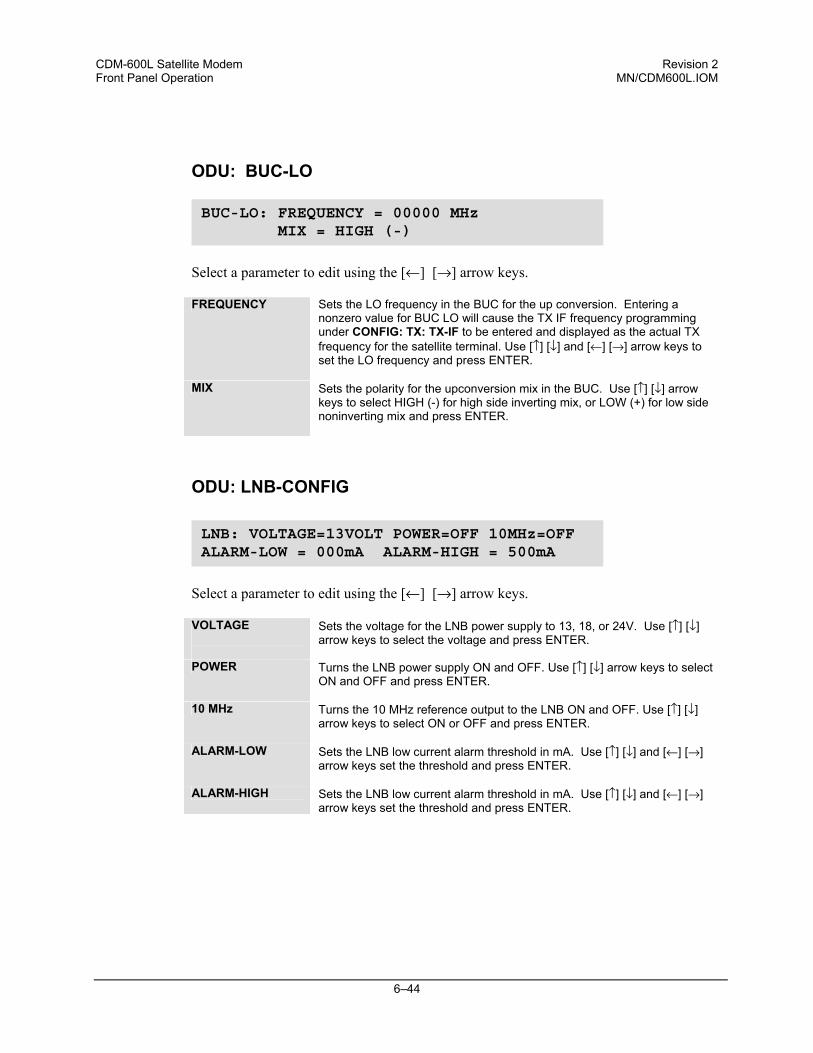
CDM-600L Satellite Modem Revision 2 Front Panel Operation MN/CDM600L.IOM
6–44
ODU: BUC-LO
Select a parameter to edit using the [←] [→] arrow keys. FREQUENCY Sets the LO frequency in the BUC for the up conversion. Entering a
nonzero value for BUC LO will cause the TX IF frequency programming under CONFIG: TX: TX-IF to be entered and displayed as the actual TX frequency for the satellite terminal. Use [↑] [↓] and [←] [→] arrow keys to set the LO frequency and press ENTER.
MIX Sets the polarity for the upconversion mix in the BUC. Use [↑] [↓] arrow keys to select HIGH (-) for high side inverting mix, or LOW (+) for low side noninverting mix and press ENTER.
ODU: LNB-CONFIG
Select a parameter to edit using the [←] [→] arrow keys.
VOLTAGE
Sets the voltage for the LNB power supply to 13, 18, or 24V. Use [↑] [↓] arrow keys to select the voltage and press ENTER.
POWER Turns the LNB power supply ON and OFF. Use [↑] [↓] arrow keys to select ON and OFF and press ENTER.
10 MHz Turns the 10 MHz reference output to the LNB ON and OFF. Use [↑] [↓] arrow keys to select ON or OFF and press ENTER.
ALARM-LOW Sets the LNB low current alarm threshold in mA. Use [↑] [↓] and [←] [→] arrow keys set the threshold and press ENTER.
ALARM-HIGH Sets the LNB low current alarm threshold in mA. Use [↑] [↓] and [←] [→] arrow keys set the threshold and press ENTER.
BUC-LO: FREQUENCY = 00000 MHz MIX = HIGH (-)
LNB: VOLTAGE=13VOLT POWER=OFF 10MHz=OFF ALARM-LOW = 000mA ALARM-HIGH = 500mA

CDM-600L Satellite Modem Revision 2 Front Panel Operation MN/CDM600L.IOM
6–45
ODU: LNB-LO
Select a parameter to edit using the [←] [→] arrow keys.
FREQUENCY
Sets the LO frequency in the LNB for the downconversion. Entering a nonzero value for LNB LO will cause the RX IF frequency programming under CONFIG: RX: RX-IF to be entered and displayed as the actual RX frequency for the satellite terminal. Use [↑] [↓] and [←] [→] arrow keys to set the LO frequency and press ENTER.
MIX Sets the polarity for the upconversion mix in the LNB. Use [↑] [↓] arrow keys to select HIGH (-) for high side inverting mix, or LOW (+) for low side noninverting mix and press ENTER.
LNB-LO: FREQUENCY = 00000 MHz MIX = HIGH (-)
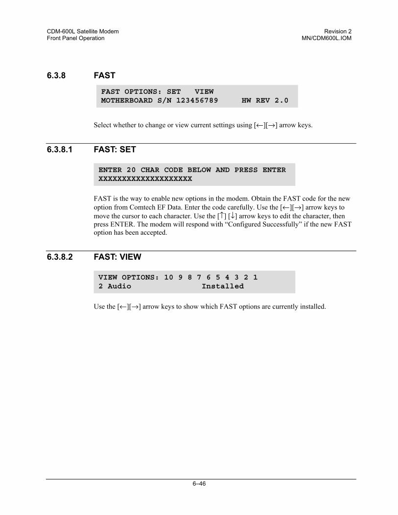
CDM-600L Satellite Modem Revision 2 Front Panel Operation MN/CDM600L.IOM
6–46
6.3.8 FAST
Select whether to change or view current settings using [←][→] arrow keys.
6.3.8.1 FAST: SET
FAST is the way to enable new options in the modem. Obtain the FAST code for the new option from Comtech EF Data. Enter the code carefully. Use the [←][→] arrow keys to move the cursor to each character. Use the [↑] [↓] arrow keys to edit the character, then press ENTER. The modem will respond with “Configured Successfully” if the new FAST option has been accepted.
6.3.8.2 FAST: VIEW
Use the [←][→] arrow keys to show which FAST options are currently installed.
ENTER 20 CHAR CODE BELOW AND PRESS ENTER XXXXXXXXXXXXXXXXXXXX
VIEW OPTIONS: 10 9 8 7 6 5 4 3 2 12 Audio Installed
FAST OPTIONS: SET VIEWMOTHERBOARD S/N 123456789 HW REV 2.0
7–1
Chapter 7. FORWARD ERROR CORRECTION OPTIONS
7.1 Introduction
As standard, the CDM-600L Modem is equipped with four Forward Error Correction encoders/decoders – Viterbi, Sequential, concatenated Reed-Solomon and Trellis (TCM) (which is available with the 8-PSK FAST option). The constraint lengths and encoding polynomials are not only Open Network compatible, but are also Closed Network compatible with the vast majority of existing modems from other manufacturers. Comtech EF Data has performed compatibility testing to ensure inter-operability. Turbo Coding represents a very significant development in the area of FEC, and optionally, the CDM-600L may be fitted with one of three Turbo Product Codecs They are plug-in daughter cards (SIMM modules), both field upgradeable. The Low Rate option provides data rate capability up to 5 Mbps, and code rates limited to Rate 5/16 (BPSK, Rate 21/44 (BPSK) and Rate 3/4 (QPSK, OQPSK, 8-PSK and 16-QAM). The High Rate option provides data rate capability up to 20 Mbps, in addition to Rate 7/8 and Rate 0.95 capability. Now, Low-Density Parity Check (LDPC) coding is being offered in addition to the TPC options. In some instances this provides even better performance than TPC. A third option card, again field upgradeable, combines LDPC and TPC together on one module. This provides the best Forward Error Correction technology currently available, and is offered with a sufficient range of code rates and modulation types that link performance can be optimized under any conditions.
7.2 Viterbi
The combination of convolutional coding and Viterbi decoding has become an almost universal standard for satellite communications. The CDM-600L complies with the Intelsat
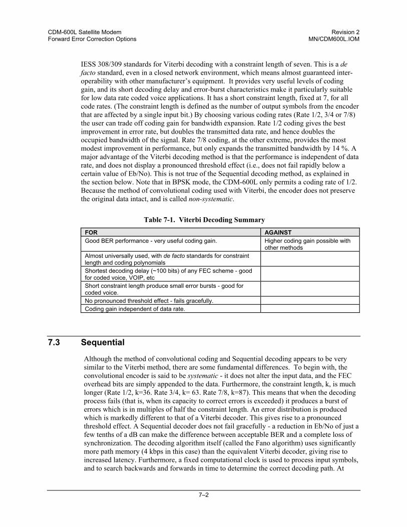
CDM-600L Satellite Modem Revision 2 Forward Error Correction Options MN/CDM600L.IOM
7–2
IESS 308/309 standards for Viterbi decoding with a constraint length of seven. This is a de facto standard, even in a closed network environment, which means almost guaranteed inter-operability with other manufacturer’s equipment. It provides very useful levels of coding gain, and its short decoding delay and error-burst characteristics make it particularly suitable for low data rate coded voice applications. It has a short constraint length, fixed at 7, for all code rates. (The constraint length is defined as the number of output symbols from the encoder that are affected by a single input bit.) By choosing various coding rates (Rate 1/2, 3/4 or 7/8) the user can trade off coding gain for bandwidth expansion. Rate 1/2 coding gives the best improvement in error rate, but doubles the transmitted data rate, and hence doubles the occupied bandwidth of the signal. Rate 7/8 coding, at the other extreme, provides the most modest improvement in performance, but only expands the transmitted bandwidth by 14 %. A major advantage of the Viterbi decoding method is that the performance is independent of data rate, and does not display a pronounced threshold effect (i.e., does not fail rapidly below a certain value of Eb/No). This is not true of the Sequential decoding method, as explained in the section below. Note that in BPSK mode, the CDM-600L only permits a coding rate of 1/2. Because the method of convolutional coding used with Viterbi, the encoder does not preserve the original data intact, and is called non-systematic.
Table 7-1. Viterbi Decoding Summary
FOR AGAINST Good BER performance - very useful coding gain. Higher coding gain possible with
other methods Almost universally used, with de facto standards for constraint length and coding polynomials
Shortest decoding delay (~100 bits) of any FEC scheme - good for coded voice, VOIP, etc
Short constraint length produce small error bursts - good for coded voice.
No pronounced threshold effect - fails gracefully. Coding gain independent of data rate.
7.3 Sequential
Although the method of convolutional coding and Sequential decoding appears to be very similar to the Viterbi method, there are some fundamental differences. To begin with, the convolutional encoder is said to be systematic - it does not alter the input data, and the FEC overhead bits are simply appended to the data. Furthermore, the constraint length, k, is much longer (Rate 1/2, k=36. Rate 3/4, k= 63. Rate 7/8, k=87). This means that when the decoding process fails (that is, when its capacity to correct errors is exceeded) it produces a burst of errors which is in multiples of half the constraint length. An error distribution is produced which is markedly different to that of a Viterbi decoder. This gives rise to a pronounced threshold effect. A Sequential decoder does not fail gracefully - a reduction in Eb/No of just a few tenths of a dB can make the difference between acceptable BER and a complete loss of synchronization. The decoding algorithm itself (called the Fano algorithm) uses significantly more path memory (4 kbps in this case) than the equivalent Viterbi decoder, giving rise to increased latency. Furthermore, a fixed computational clock is used to process input symbols, and to search backwards and forwards in time to determine the correct decoding path. At
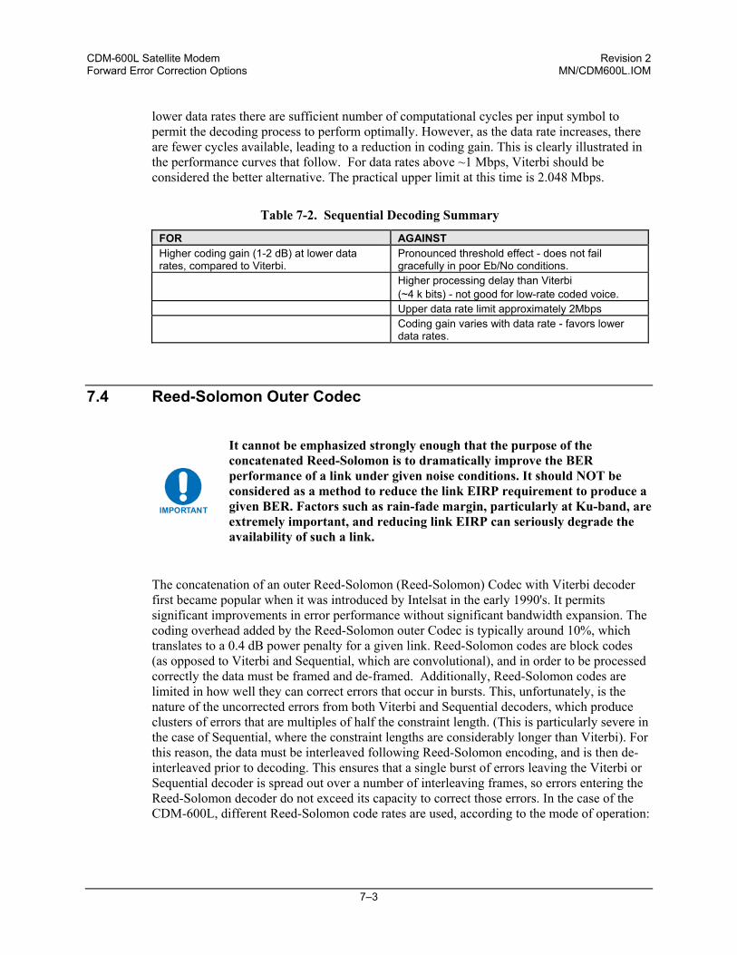
CDM-600L Satellite Modem Revision 2 Forward Error Correction Options MN/CDM600L.IOM
7–3
lower data rates there are sufficient number of computational cycles per input symbol to permit the decoding process to perform optimally. However, as the data rate increases, there are fewer cycles available, leading to a reduction in coding gain. This is clearly illustrated in the performance curves that follow. For data rates above ~1 Mbps, Viterbi should be considered the better alternative. The practical upper limit at this time is 2.048 Mbps.
Table 7-2. Sequential Decoding Summary
FOR AGAINST Higher coding gain (1-2 dB) at lower data rates, compared to Viterbi.
Pronounced threshold effect - does not fail gracefully in poor Eb/No conditions.
Higher processing delay than Viterbi (~4 k bits) - not good for low-rate coded voice.
Upper data rate limit approximately 2Mbps Coding gain varies with data rate - favors lower
data rates.
7.4 Reed-Solomon Outer Codec
IMPORTANT
It cannot be emphasized strongly enough that the purpose of the concatenated Reed-Solomon is to dramatically improve the BER performance of a link under given noise conditions. It should NOT be considered as a method to reduce the link EIRP requirement to produce a given BER. Factors such as rain-fade margin, particularly at Ku-band, are extremely important, and reducing link EIRP can seriously degrade the availability of such a link.
The concatenation of an outer Reed-Solomon (Reed-Solomon) Codec with Viterbi decoder first became popular when it was introduced by Intelsat in the early 1990's. It permits significant improvements in error performance without significant bandwidth expansion. The coding overhead added by the Reed-Solomon outer Codec is typically around 10%, which translates to a 0.4 dB power penalty for a given link. Reed-Solomon codes are block codes (as opposed to Viterbi and Sequential, which are convolutional), and in order to be processed correctly the data must be framed and de-framed. Additionally, Reed-Solomon codes are limited in how well they can correct errors that occur in bursts. This, unfortunately, is the nature of the uncorrected errors from both Viterbi and Sequential decoders, which produce clusters of errors that are multiples of half the constraint length. (This is particularly severe in the case of Sequential, where the constraint lengths are considerably longer than Viterbi). For this reason, the data must be interleaved following Reed-Solomon encoding, and is then de-interleaved prior to decoding. This ensures that a single burst of errors leaving the Viterbi or Sequential decoder is spread out over a number of interleaving frames, so errors entering the Reed-Solomon decoder do not exceed its capacity to correct those errors. In the case of the CDM-600L, different Reed-Solomon code rates are used, according to the mode of operation:
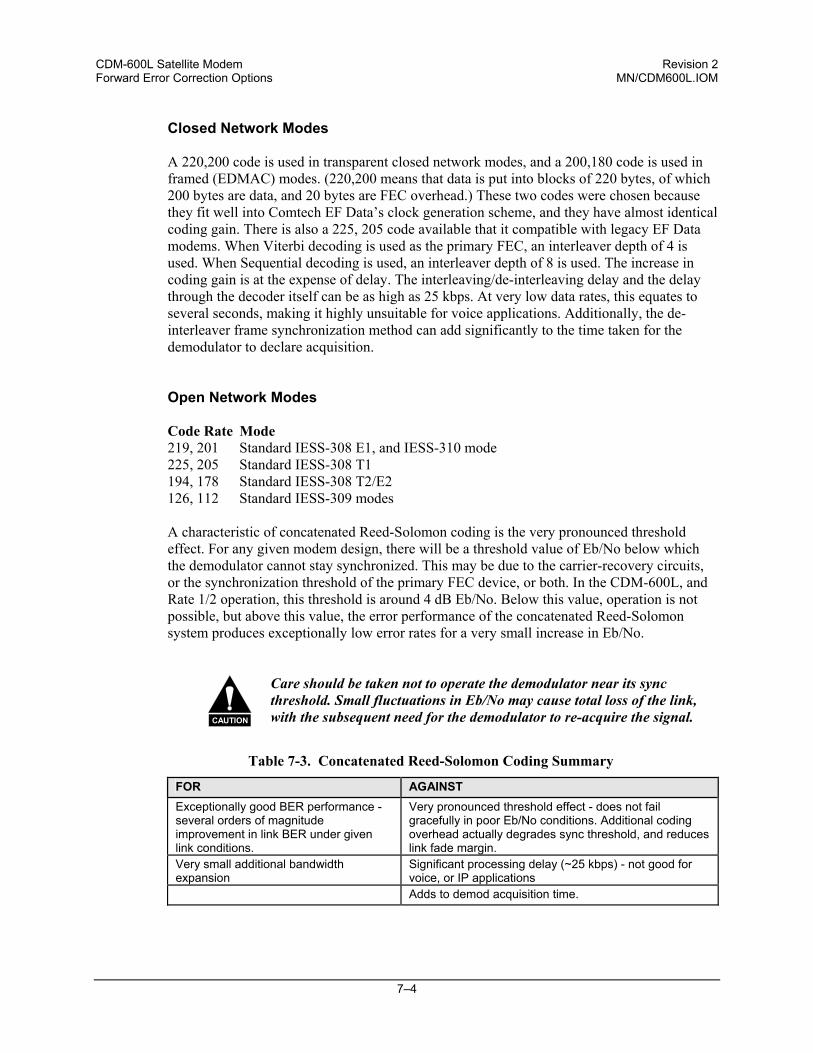
CDM-600L Satellite Modem Revision 2 Forward Error Correction Options MN/CDM600L.IOM
7–4
Closed Network Modes A 220,200 code is used in transparent closed network modes, and a 200,180 code is used in framed (EDMAC) modes. (220,200 means that data is put into blocks of 220 bytes, of which 200 bytes are data, and 20 bytes are FEC overhead.) These two codes were chosen because they fit well into Comtech EF Data’s clock generation scheme, and they have almost identical coding gain. There is also a 225, 205 code available that it compatible with legacy EF Data modems. When Viterbi decoding is used as the primary FEC, an interleaver depth of 4 is used. When Sequential decoding is used, an interleaver depth of 8 is used. The increase in coding gain is at the expense of delay. The interleaving/de-interleaving delay and the delay through the decoder itself can be as high as 25 kbps. At very low data rates, this equates to several seconds, making it highly unsuitable for voice applications. Additionally, the de-interleaver frame synchronization method can add significantly to the time taken for the demodulator to declare acquisition. Open Network Modes Code Rate Mode 219, 201 Standard IESS-308 E1, and IESS-310 mode 225, 205 Standard IESS-308 T1 194, 178 Standard IESS-308 T2/E2 126, 112 Standard IESS-309 modes A characteristic of concatenated Reed-Solomon coding is the very pronounced threshold effect. For any given modem design, there will be a threshold value of Eb/No below which the demodulator cannot stay synchronized. This may be due to the carrier-recovery circuits, or the synchronization threshold of the primary FEC device, or both. In the CDM-600L, and Rate 1/2 operation, this threshold is around 4 dB Eb/No. Below this value, operation is not possible, but above this value, the error performance of the concatenated Reed-Solomon system produces exceptionally low error rates for a very small increase in Eb/No.
CAUTION
Care should be taken not to operate the demodulator near its sync threshold. Small fluctuations in Eb/No may cause total loss of the link, with the subsequent need for the demodulator to re-acquire the signal.
Table 7-3. Concatenated Reed-Solomon Coding Summary
FOR AGAINST Exceptionally good BER performance - several orders of magnitude improvement in link BER under given link conditions.
Very pronounced threshold effect - does not fail gracefully in poor Eb/No conditions. Additional coding overhead actually degrades sync threshold, and reduces link fade margin.
Very small additional bandwidth expansion
Significant processing delay (~25 kbps) - not good for voice, or IP applications
Adds to demod acquisition time.
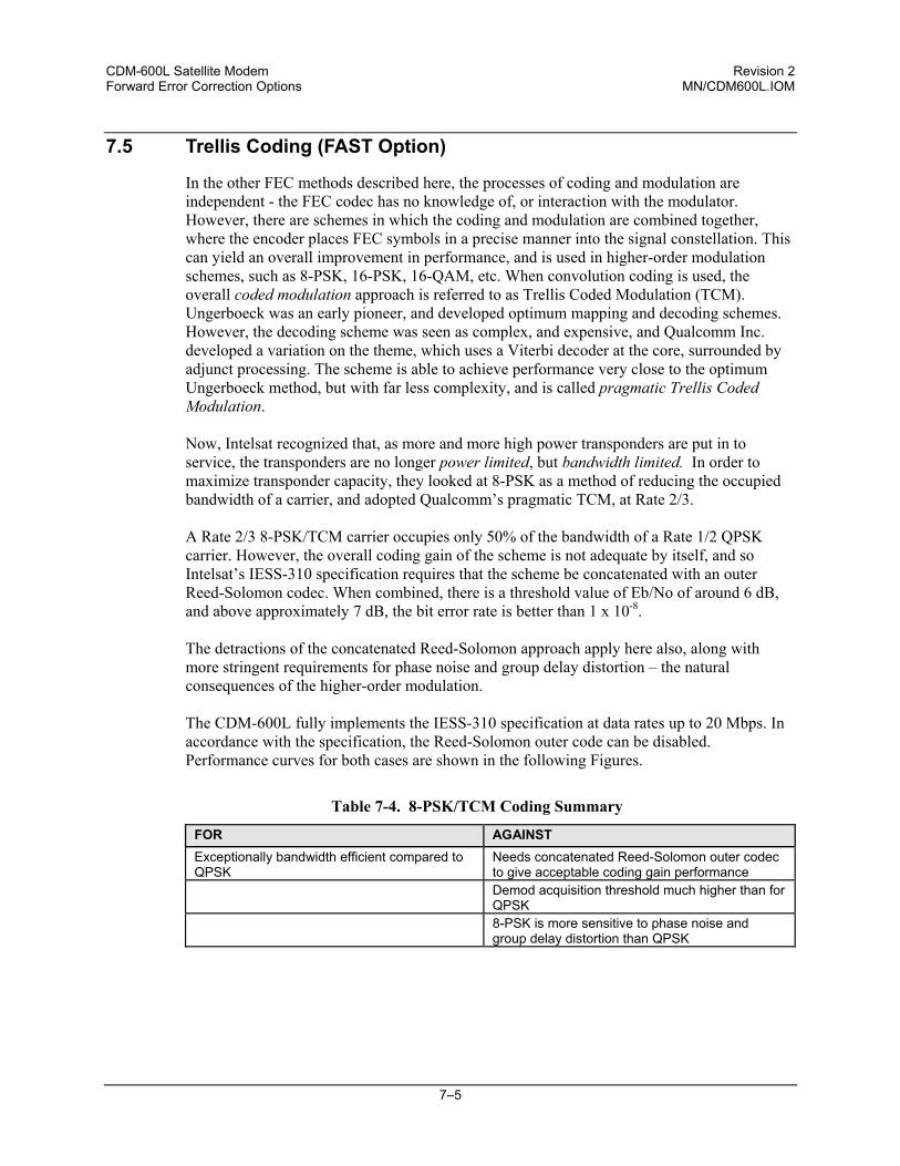
CDM-600L Satellite Modem Revision 2 Forward Error Correction Options MN/CDM600L.IOM
7–5
7.5 Trellis Coding (FAST Option)
In the other FEC methods described here, the processes of coding and modulation are independent - the FEC codec has no knowledge of, or interaction with the modulator. However, there are schemes in which the coding and modulation are combined together, where the encoder places FEC symbols in a precise manner into the signal constellation. This can yield an overall improvement in performance, and is used in higher-order modulation schemes, such as 8-PSK, 16-PSK, 16-QAM, etc. When convolution coding is used, the overall coded modulation approach is referred to as Trellis Coded Modulation (TCM). Ungerboeck was an early pioneer, and developed optimum mapping and decoding schemes. However, the decoding scheme was seen as complex, and expensive, and Qualcomm Inc. developed a variation on the theme, which uses a Viterbi decoder at the core, surrounded by adjunct processing. The scheme is able to achieve performance very close to the optimum Ungerboeck method, but with far less complexity, and is called pragmatic Trellis Coded Modulation. Now, Intelsat recognized that, as more and more high power transponders are put in to service, the transponders are no longer power limited, but bandwidth limited. In order to maximize transponder capacity, they looked at 8-PSK as a method of reducing the occupied bandwidth of a carrier, and adopted Qualcomm’s pragmatic TCM, at Rate 2/3. A Rate 2/3 8-PSK/TCM carrier occupies only 50% of the bandwidth of a Rate 1/2 QPSK carrier. However, the overall coding gain of the scheme is not adequate by itself, and so Intelsat’s IESS-310 specification requires that the scheme be concatenated with an outer Reed-Solomon codec. When combined, there is a threshold value of Eb/No of around 6 dB, and above approximately 7 dB, the bit error rate is better than 1 x 10⁻⁸. The detractions of the concatenated Reed-Solomon approach apply here also, along with more stringent requirements for phase noise and group delay distortion – the natural consequences of the higher-order modulation. The CDM-600L fully implements the IESS-310 specification at data rates up to 20 Mbps. In accordance with the specification, the Reed-Solomon outer code can be disabled. Performance curves for both cases are shown in the following Figures.
Table 7-4. 8-PSK/TCM Coding Summary
FOR AGAINST Exceptionally bandwidth efficient compared to QPSK
Needs concatenated Reed-Solomon outer codec to give acceptable coding gain performance
Demod acquisition threshold much higher than for QPSK
8-PSK is more sensitive to phase noise and group delay distortion than QPSK
CDM-600L Satellite Modem Revision 2 Forward Error Correction Options MN/CDM600L.IOM
7–6
7.6 Turbo Product Codec (Hardware Option)
Turbo coding is an FEC technique developed within the last few years, which delivers significant performance improvements compared to more traditional techniques. Two general classes of Turbo Codes have been developed, Turbo Convolutional Codes (TCC), and Turbo Product Codes (TPC, a block coding technique). Comtech EF Data has chosen to implement an FEC codec based on TPC. A Turbo Product Code is a 2 or 3 dimensional array of block codes. Encoding is relatively straightforward, but decoding is a very complex process requiring multiple iterations of processing for maximum performance to be achieved. Unlike the popular method of concatenating a Reed-Solomon codec with a primary FEC codec, Turbo Product Coding is an entirely stand-alone method. It does not require the complex interleaving/de-interleaving of the Reed-Solomon approach, and consequently, decoding delays are significantly reduced. Furthermore, the traditional concatenated Reed-Solomon schemes exhibit a very pronounced threshold effect – a small reduction in Eb/No can result in total loss of demod and decoder synchronization. TPC does not suffer from this problem – the demod and decoder remain synchronized down to the point where the output error rate becomes unusable. This is considered to be a particularly advantageous characteristic in a fading environment. Typically, in QPSK, 8-PSK and 16-QAM TPC modes the demod and decoder can remain synchronized 2 – 3 dB below the Viterbi/Reed-Solomon or TCM cases.
7.7 TPC and Low Density Parity Check (LDPC) coding
7.7.1 Introduction
In the past few years there has been an unprecedented resurgence in interest in Forward Error Correction (FEC) technology. The start of this new interest has its origins in the work done by Claude Berrou et al, and the landmark paper in 1993 - Near Shannon Limit Error Correcting Coding and Decoding - Turbo Codes. FEC is considered an essential component in all wireless and satellite communications in order to reduce the power and bandwidth requirements for reliable data transmission. Claude Shannon, considered by many to be the father of modern communications theory, first established, in his 1948 paper A Mathematical Theory of Communication, the concept of Channel Capacity. This places an absolute limit on how fast it is possible to transmit error-free data within a channel of a given bandwidth, and with given noise conditions within that channel. He concluded that it would only be possible to approach this limit through the use of source encoding - what is familiar today as Forward Error Correction. He postulated that if it were possible to store every possible message in the receiver, finding the stored message that most closely matched the incoming message would yield an optimum decoding method. However, for all but the shortest bit sequences, the memory required for this, and the time taken to perform the comparisons, makes this approach impractical. For all practical purposes, the memory requirement and the decoding latency become infinite. For many years there were few advances in the quest to approach the Shannon Limit. The Viterbi algorithm heralded a major step forward, followed in the early 1990s by the
CDM-600L Satellite Modem Revision 2 Forward Error Correction Options MN/CDM600L.IOM
7–7
concatenation of a Viterbi decoder with Reed-Solomon hard-decision block codes. However, it remained clear that the Shannon Limit was still an elusive target. Berrou’s work on Turbo Codes showed, through the use of an ingeniously simple approach (multiple, or iterative decoding passes) that it is possible to achieve performance close to the Shannon Limit. Berrou’s early work dealt exclusively with iteratively-decoded convolutional codes (Turbo Convolutional Coding, or TCC), but in time the iterative approach was applied to a particular class of block codes called Product Codes - hence Turbo Product Coding (TPC). TPC exhibits inherently low decoding latency compared with TCC, and so is considered much more desirable for 2-way, interactive satellite communications applications.
In August 1999, Comtech became the first company in the world to offer, on a commercial basis, satellite modems that incorporate TPC. Since its inception, Comtech has continued to develop and refine its implementation of TPC in its products, and now offers a comprehen-sive range of code rates (from Rate 5/16 to Rate 0.95) and modulations (from BPSK to 16-QAM). However, in the past few years, as part of the general interest in Turbo coding, a third class of Turbo coding has emerged, namely Low Density Parity Check Codes (LDPC). It is more like TPC than TCC, in that it is an iteratively-decoded block code. Gallager first sug-gested this in 1962, but at the time, the implementation complexity was considered to be too great, and for decades it remained of purely academic interest. Now, however, with silicon gates being cheap, plentiful and fast, an LDPC decoder can easily be accommodated in a large Field Programmable Gate Array (FPGA) device. Further interest in LDPC was stimu-lated in 2003, when the Digital Video Broadcasting (DVB) committee adopted LDPC codes (proposed by Hughes Network Systems) as the basis for the new DVB-S2 standard. The LDPC method on its own produces an undesirable ‘flaring’ in the Bit Error Rate (BER) vs. Eb/No characteristic, and for this reason it is desirable to concatenate a short BCH code with LDPC. This concatenation produces almost vertical BER vs. Eb/No curves, as can be seen in the performance graphs that are presented later. In order to take full advantage of the coding gain increase that LDPC provides, it became necessary to find an alternative to 8-PSK. Comtech EF Data has therefore developed an 8-QAM approach that permits acquisition and tracking at much lower values of Eb/No than 8-PSK. A discussion of this approach follows. Comtech EF Data chose the CDM-600 platform as the first satellite modem in which to implement both LDPC and 8-QAM, followed by this modem, the CDM-600L.
7.7.2 LDPC versus TPC
So, is LDPC better than TPC? The answer must be ‘sometimes, but not always’, and there are issues, such as latency, that must be taken into consideration. The graph shown below illustrates the performance of various TPC and LDPC modes relative to the Shannon Limit - the Channel Capacity is shown for both QPSK and 8-PSK. Error-free transmission is not possible for values of spectral efficiency (capacity) vs. Eb/No above these limit curves. The horizontal distance to the limit provides a metric of overall performance. It can be seen from this graph that for Code Rates above 3/4, Comtech’s TPCs are very close (1 - 1.5 dB) to the Shannon Limit. However, at 3/4 and below, LDPCs are performing 0.7 - 1.2 dB better than TPCs.
CDM-600L Satellite Modem Revision 2 Forward Error Correction Options MN/CDM600L.IOM
7–8
It is clear that in order to provide the best possible performance over the range of code rates from 1/2 to 0.95, both an LDPC and a TPC codec need to be offered. In order to meet this requirement, Comtech EF Data has developed a combination LDPC/TPC Codec module that can be added to the CDM-600L Modem, and which provides the following operating modes:
Table 7-5. Available TPC and LDPC Modes
TPC Code Rate/Modulation Data Rate Range Rate 21/44 BPSK 4.8 kbps to 3.2 Mbps (to 4.772 Mbps with High Rate Turbo card) Rate 5/16 BPSK 4.8 kbps to 2.048 Mbps (to 3.12 Mbps with High Rate Turbo card) Rate 1/2 QPSK, OQPSK 4.8 kbps to 9.54 Mbps (High Rate Turbo card only) Rate 3/4 QPSK, OQPSK 7.2 kbps to 5.0 Mbps (to 15 Mbps with High Rate Turbo card) Rate 3/4 8-PSK 10.8 kbps to 5.0 Mbps (to 20 Mbps with High Rate Turbo card) Rate 3/4 16-QAM 14.4 kbps to 5.0 Mbps (to 20 Mbps with High Rate Turbo card) Rate 7/8 QPSK, OQPSK 8.4 kbps to 17.5 Mbps (High Rate Turbo card only) Rate 7/8 8-PSK 12.6 kbps to 20 Mbps (High Rate Turbo card only) Rate 7/8 16-QAM 16.8 kbps to 20 Mbps (High Rate Turbo card only) Rate 0.95 QPSK, OQPSK 9.1 kbps to 18.888 Mbps (High Rate Turbo card only) Rate 0.95 8-PSK 13.6 kbps to 20 Mbps (High Rate Turbo card only) LDPC Code Rate/Modulation Data Rate Range Rate 1/2 BPSK 4.8 kbps to 5.0 Mbps (TPC/LDPC Codec card only) Rate 1/2 QPSK, OQPSK 4.8 kbps to 10.0 Mbps (TPC/LDPC Codec card only) Rate 2/3 QPSK, OQPSK 6.4 kbps to 13.3 Mbps (TPC/LDPC Codec card only) Rate 2/3 8-PSK , 8-QAM 9.6 kbps to 19.0 Mbps (TPC/LDPC Codec card only) Rate 3/4 QPSK, OQPSK 7.2 kbps to 15.0 Mbps (TPC/LDPC Codec card only) Rate 3/4 8-PSK , 8-QAM 10.8 kbps to 20.0 Mbps (TPC/LDPC Codec card only) Rate 3/4 16-QAM 14.4 kbps to 20.0 Mbps (TPC/LDPC Codec card only)
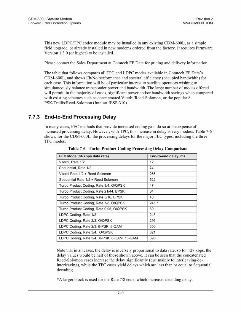
CDM-600L Satellite Modem Revision 2 Forward Error Correction Options MN/CDM600L.IOM
7–9
This new LDPC/TPC codec module may be installed in any existing CDM-600L, as a simple field upgrade, or already installed in new modems ordered from the factory. It requires Firmware Version 1.3.0 (or higher) to be installed. Please contact the Sales Department at Comtech EF Data for pricing and delivery information. The table that follows compares all TPC and LDPC modes available in Comtech EF Data’s CDM-600L, and shows Eb/No performance and spectral efficiency (occupied bandwidth) for each case. This information will be of particular interest to satellite operators wishing to simultaneously balance transponder power and bandwidth. The large number of modes offered will permit, in the majority of cases, significant power and/or bandwidth savings when compared with existing schemes such as concatenated Viterbi/Reed-Solomon, or the popular 8-PSK/Trellis/Reed-Solomon (Intelsat IESS-310)
7.7.3 End-to-End Processing Delay
In many cases, FEC methods that provide increased coding gain do so at the expense of increased processing delay. However, with TPC, this increase in delay is very modest. Table 7-6 shows, for the CDM-600L, the processing delays for the major FEC types, including the three TPC modes:
Table 7-6. Turbo Product Coding Processing Delay Comparison
FEC Mode (64 kbps data rate) End-to-end delay, ms Viterbi, Rate 1/2 12 Sequential, Rate 1/2 74 Viterbi Rate 1/2 + Reed Solomon 266 Sequential Rate 1/2 + Reed Solomon 522 Turbo Product Coding, Rate 3/4, O/QPSK 47 Turbo Product Coding, Rate 21/44, BPSK 64 Turbo Product Coding, Rate 5/16, BPSK 48 Turbo Product Coding, Rate 7/8, O/QPSK 245 * Turbo Product Coding, Rate 0.95, O/QPSK 69 LDPC Coding, Rate 1/2 248 LDPC Coding, Rate 2/3, O/QPSK 296 LDPC Coding, Rate 2/3, 8-PSK, 8-QAM 350 LDPC Coding, Rate 3/4, O/QPSK 321 LDPC Coding, Rate 3/4, 8-PSK, 8-QAM, 16-QAM 395
Note that in all cases, the delay is inversely proportional to data rate, so for 128 kbps, the delay values would be half of those shown above. It can be seen that the concatenated Reed-Solomon cases increase the delay significantly (due mainly to interleaving/de-interleaving), while the TPC cases yield delays which are less than or equal to Sequential decoding. *A larger block is used for the Rate 7/8 code, which increases decoding delay.
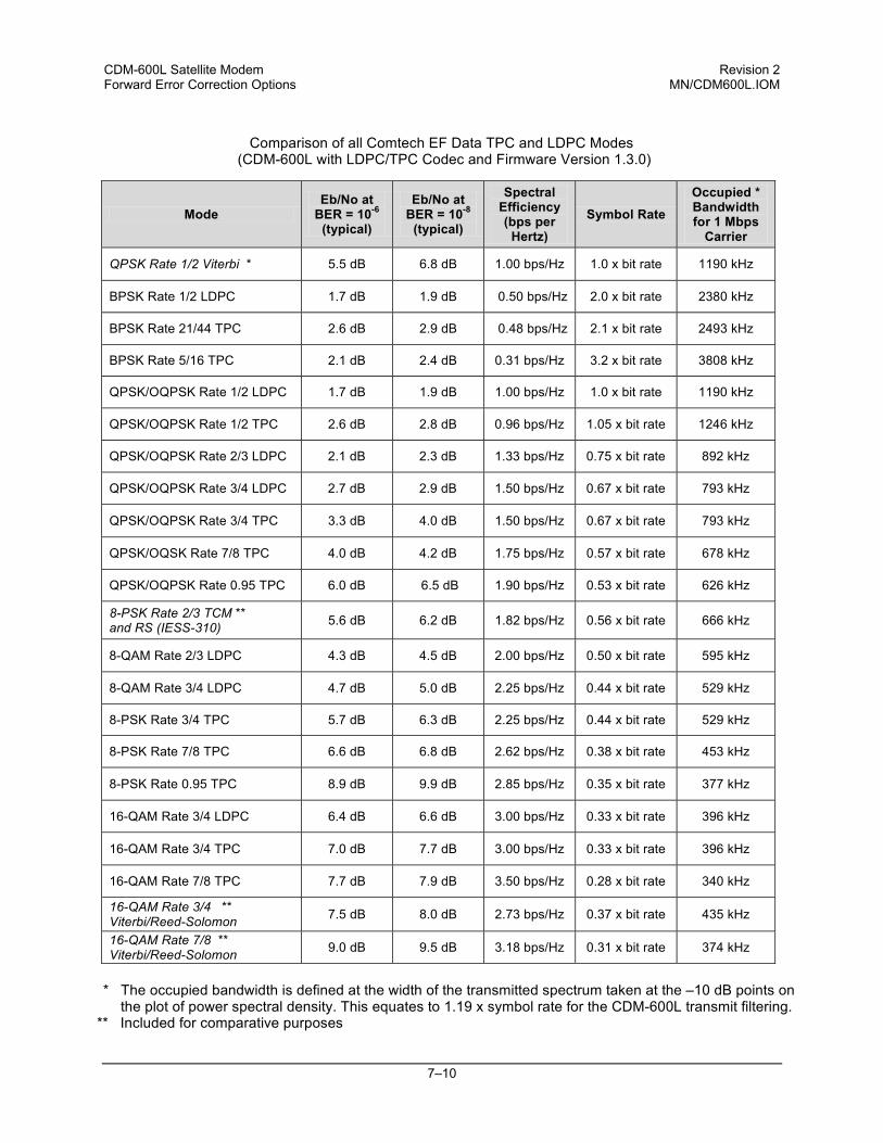
CDM-600L Satellite Modem Revision 2 Forward Error Correction Options MN/CDM600L.IOM
7–10
Comparison of all Comtech EF Data TPC and LDPC Modes (CDM-600L with LDPC/TPC Codec and Firmware Version 1.3.0)
Mode Eb/No at
BER = 10-6
(typical)
Eb/No at BER = 10-8
(typical)
Spectral Efficiency (bps per
Hertz) Symbol Rate
Occupied * Bandwidth for 1 Mbps
Carrier
QPSK Rate 1/2 Viterbi * 5.5 dB 6.8 dB 1.00 bps/Hz 1.0 x bit rate 1190 kHz
BPSK Rate 1/2 LDPC 1.7 dB 1.9 dB 0.50 bps/Hz 2.0 x bit rate 2380 kHz
BPSK Rate 21/44 TPC 2.6 dB 2.9 dB 0.48 bps/Hz 2.1 x bit rate 2493 kHz
BPSK Rate 5/16 TPC 2.1 dB 2.4 dB 0.31 bps/Hz 3.2 x bit rate 3808 kHz
QPSK/OQPSK Rate 1/2 LDPC 1.7 dB 1.9 dB 1.00 bps/Hz 1.0 x bit rate 1190 kHz
QPSK/OQPSK Rate 1/2 TPC 2.6 dB 2.8 dB 0.96 bps/Hz 1.05 x bit rate 1246 kHz
QPSK/OQPSK Rate 2/3 LDPC 2.1 dB 2.3 dB 1.33 bps/Hz 0.75 x bit rate 892 kHz
QPSK/OQPSK Rate 3/4 LDPC 2.7 dB 2.9 dB 1.50 bps/Hz 0.67 x bit rate 793 kHz
QPSK/OQPSK Rate 3/4 TPC 3.3 dB 4.0 dB 1.50 bps/Hz 0.67 x bit rate 793 kHz
QPSK/OQSK Rate 7/8 TPC 4.0 dB 4.2 dB 1.75 bps/Hz 0.57 x bit rate 678 kHz
QPSK/OQPSK Rate 0.95 TPC 6.0 dB 6.5 dB 1.90 bps/Hz 0.53 x bit rate 626 kHz
8-PSK Rate 2/3 TCM ** and RS (IESS-310) 5.6 dB 6.2 dB 1.82 bps/Hz 0.56 x bit rate 666 kHz
8-QAM Rate 2/3 LDPC 4.3 dB 4.5 dB 2.00 bps/Hz 0.50 x bit rate 595 kHz
8-QAM Rate 3/4 LDPC 4.7 dB 5.0 dB 2.25 bps/Hz 0.44 x bit rate 529 kHz
8-PSK Rate 3/4 TPC 5.7 dB 6.3 dB 2.25 bps/Hz 0.44 x bit rate 529 kHz
8-PSK Rate 7/8 TPC 6.6 dB 6.8 dB 2.62 bps/Hz 0.38 x bit rate 453 kHz
8-PSK Rate 0.95 TPC 8.9 dB 9.9 dB 2.85 bps/Hz 0.35 x bit rate 377 kHz
16-QAM Rate 3/4 LDPC 6.4 dB 6.6 dB 3.00 bps/Hz 0.33 x bit rate 396 kHz
16-QAM Rate 3/4 TPC 7.0 dB 7.7 dB 3.00 bps/Hz 0.33 x bit rate 396 kHz
16-QAM Rate 7/8 TPC 7.7 dB 7.9 dB 3.50 bps/Hz 0.28 x bit rate 340 kHz
16-QAM Rate 3/4 ** Viterbi/Reed-Solomon 7.5 dB 8.0 dB 2.73 bps/Hz 0.37 x bit rate 435 kHz
16-QAM Rate 7/8 ** Viterbi/Reed-Solomon 9.0 dB 9.5 dB 3.18 bps/Hz 0.31 x bit rate 374 kHz
* The occupied bandwidth is defined at the width of the transmitted spectrum taken at the –10 dB points on
the plot of power spectral density. This equates to 1.19 x symbol rate for the CDM-600L transmit filtering. ** Included for comparative purposes
CDM-600L Satellite Modem Revision 2 Forward Error Correction Options MN/CDM600L.IOM
7–11
Table 7-7. TPC and LDPC Summary
FOR AGAINST Exceptionally good BER performance - significant improvement compared with every other FEC method in use today
Nothing!
Most modes have no pronounced threshold effect - fails gracefully Exceptional bandwidth efficiency Coding gain independent of data rate (in this implementation) Low decoding delay for TPC Easy field upgrade in CDM-600L
7.8 Uncoded Operation (No FEC)
There are occasions where a user may wish to operate a satellite link with no forward error correction of any kind. For this reason, the CDM-600L offers this uncoded mode for three modulation types - BPSK, QPSK, and OQPSK. However, the user should be aware of some of the implications of using this approach. PSK demodulators have two inherent undesirable features. The first of these is known as ‘phase ambiguity’, and is due to the fact the demodulator does not have any absolute phase reference, and in the process of carrier recovery, the demodulator can lock up in any of K phase states, where K = 2 for BPSK, K = 4 for QPSK. Without the ability to resolve these ambiguous states there would be a 1-in-2 chance that the data at the output of the demodulator would be wrong, in the case of BPSK. For QPSK, the probability would be 3 in 4. The problem is solved in the case of BPSK by differentially encoding the data prior to transmission, and then performing the inverse decoding process. This is a very simple process, but has the disadvantage that it doubles the receive BER. For every bit error the demodulator produces, the differential decoder produces two. The problem for QPSK is more complex, as there are 4 possible lock states, leading to 4 ambiguities. When FEC is employed, the lock state of the FEC decoder can be used to resolve two of the four ambiguities, and the remaining two can be resolved using serial differential encoding/decoding. However, when no FEC is being used, an entirely different scheme must be used. Therefore, in QPSK, a parallel differential encoding/decoding technique is used, but has the disadvantage that it again doubles the receive BER. OQPSK is a different situation again, where the ambiguities result not only from not having an absolute phase reference, but also not knowing which of the two parallel paths in the demod, I or Q, contains the half-symbol delay. Another type of differential encoding is used, but yet again the error rate is doubled, compared to ideal.
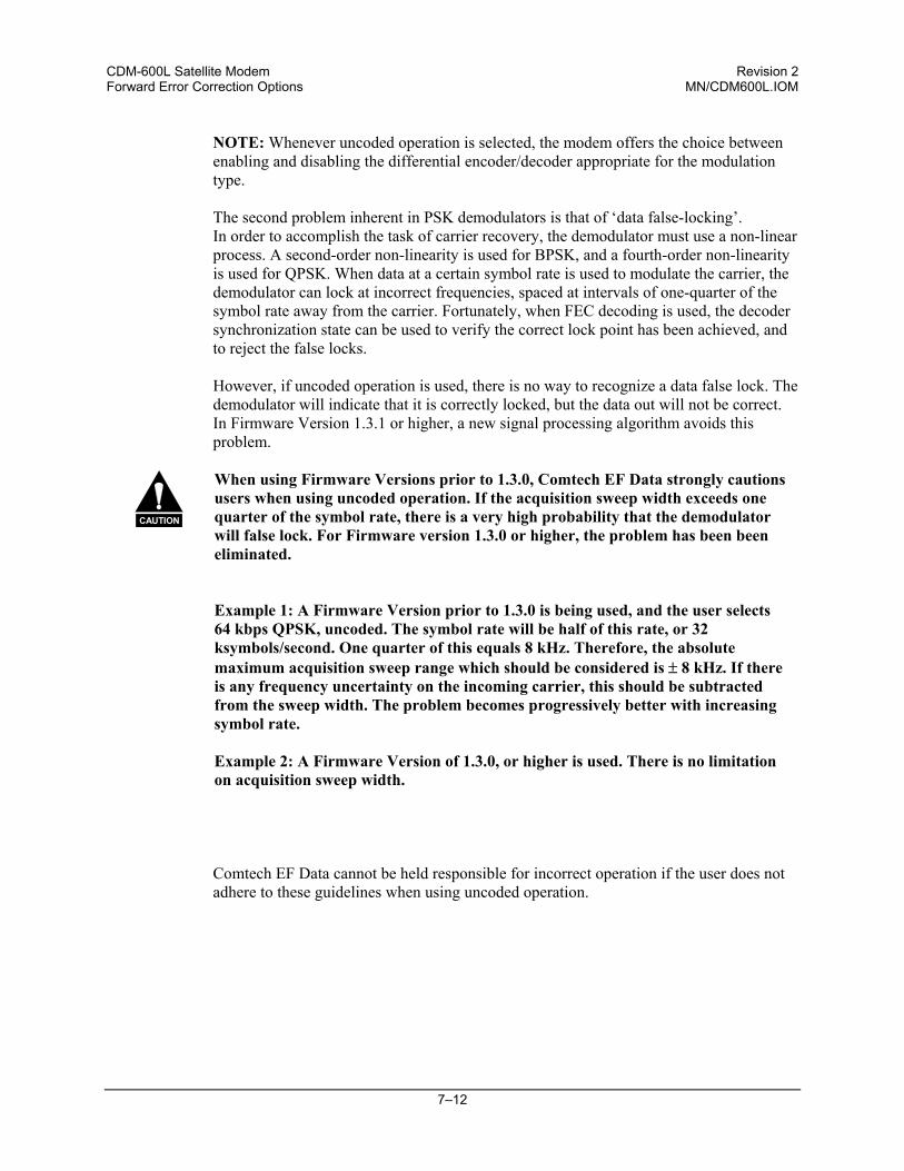
CDM-600L Satellite Modem Revision 2 Forward Error Correction Options MN/CDM600L.IOM
7–12
NOTE: Whenever uncoded operation is selected, the modem offers the choice between enabling and disabling the differential encoder/decoder appropriate for the modulation type. The second problem inherent in PSK demodulators is that of ‘data false-locking’. In order to accomplish the task of carrier recovery, the demodulator must use a non-linear process. A second-order non-linearity is used for BPSK, and a fourth-order non-linearity is used for QPSK. When data at a certain symbol rate is used to modulate the carrier, the demodulator can lock at incorrect frequencies, spaced at intervals of one-quarter of the symbol rate away from the carrier. Fortunately, when FEC decoding is used, the decoder synchronization state can be used to verify the correct lock point has been achieved, and to reject the false locks. However, if uncoded operation is used, there is no way to recognize a data false lock. The demodulator will indicate that it is correctly locked, but the data out will not be correct. In Firmware Version 1.3.1 or higher, a new signal processing algorithm avoids this problem.
CAUTION
When using Firmware Versions prior to 1.3.0, Comtech EF Data strongly cautions users when using uncoded operation. If the acquisition sweep width exceeds one quarter of the symbol rate, there is a very high probability that the demodulator will false lock. For Firmware version 1.3.0 or higher, the problem has been been eliminated.
Example 1: A Firmware Version prior to 1.3.0 is being used, and the user selects 64 kbps QPSK, uncoded. The symbol rate will be half of this rate, or 32 ksymbols/second. One quarter of this equals 8 kHz. Therefore, the absolute maximum acquisition sweep range which should be considered is ± 8 kHz. If there is any frequency uncertainty on the incoming carrier, this should be subtracted from the sweep width. The problem becomes progressively better with increasing symbol rate. Example 2: A Firmware Version of 1.3.0, or higher is used. There is no limitation on acquisition sweep width.
Comtech EF Data cannot be held responsible for incorrect operation if the user does not adhere to these guidelines when using uncoded operation.
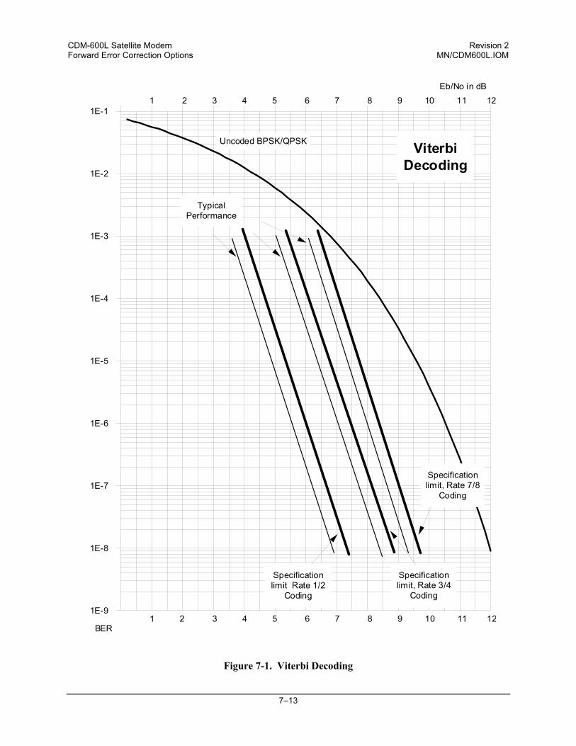
CDM-600L Satellite Modem Revision 2 Forward Error Correction Options MN/CDM600L.IOM
7–13
Figure 7-1. Viterbi Decoding
1E-9
1E-8
1E-7
1E-6
1E-5
1E-4
1E-3
1E-2
1E-11 2 3 4 5 6 7 8 9 10 11 12
Eb/No in dB
Specificationlimit Rate 1/2
Coding
Uncoded BPSK/QPSK
TypicalPerformance
Specificationlimit, Rate 3/4
Coding
1 2 3 4 5 6 7 8 9 10 11 12
Specificationlimit, Rate 7/8
Coding
BER
ViterbiDecoding
CDM-600L Satellite Modem Revision 2 Forward Error Correction Options MN/CDM600L.IOM
7–14
Figure 7-2. Sequential Decoding 64 kbps
1E-9
1E-8
1E-7
1E-6
1E-5
1E-4
1E-3
1E-2
1E-11 2 3 4 5 6 7 8 9 10 11 12
Eb/No in dB
Specificationlimit Rate 1/2
Coding
Uncoded BPSK/QPSK
TypicalPerformance
Specificationlimit, Rate 3/4
Coding
1 2 3 4 5 6 7 8 9 10 11 12
Specificationlimit, Rate 7/8
Coding
BER
SequentialDecoding64 kbps
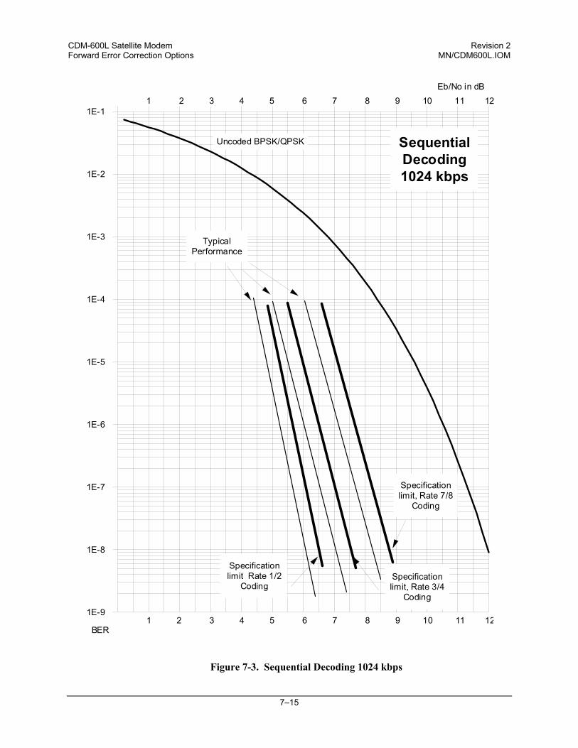
CDM-600L Satellite Modem Revision 2 Forward Error Correction Options MN/CDM600L.IOM
7–15
Figure 7-3. Sequential Decoding 1024 kbps
1E-9
1E-8
1E-7
1E-6
1E-5
1E-4
1E-3
1E-2
1E-11 2 3 4 5 6 7 8 9 10 11 12
Eb/No in dB
Specificationlimit Rate 1/2
Coding
Uncoded BPSK/QPSK
TypicalPerformance
Specificationlimit, Rate 3/4
Coding
1 2 3 4 5 6 7 8 9 10 11 12
Specificationlimit, Rate 7/8
Coding
BER
SequentialDecoding1024 kbps
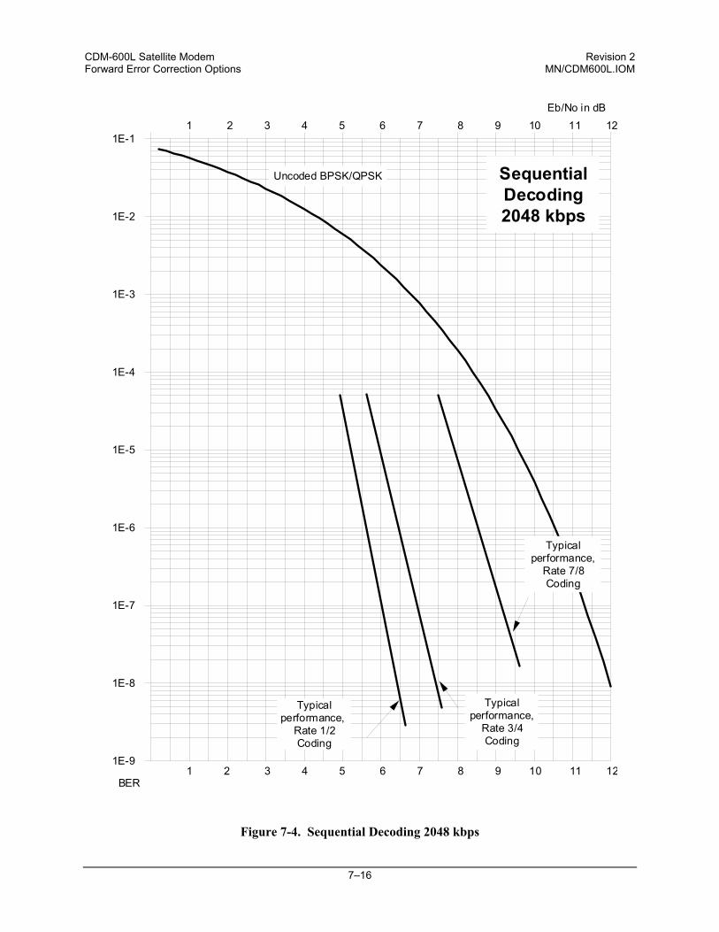
CDM-600L Satellite Modem Revision 2 Forward Error Correction Options MN/CDM600L.IOM
7–16
Figure 7-4. Sequential Decoding 2048 kbps
1E-9
1E-8
1E-7
1E-6
1E-5
1E-4
1E-3
1E-2
1E-11 2 3 4 5 6 7 8 9 10 11 12
Eb/No in dB
Typicalperformance,
Rate 1/2Coding
Uncoded BPSK/QPSK
Typicalperformance,
Rate 3/4Coding
1 2 3 4 5 6 7 8 9 10 11 12
Typicalperformance,
Rate 7/8Coding
BER
SequentialDecoding2048 kbps
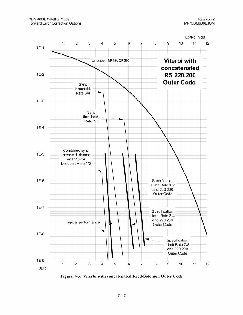
CDM-600L Satellite Modem Revision 2 Forward Error Correction Options MN/CDM600L.IOM
7–17
Figure 7-5. Viterbi with concatenated Reed-Solomon Outer Code
1E-9
1E-8
1E-7
1E-6
1E-5
1E-4
1E-3
1E-2
1E-11 2 3 4 5 6 7 8 9 10 11 12
Eb/No in dB
SpecificationLimit Rate 1/2and 220,200Outer Code
Uncoded BPSK/QPSK
1 2 3 4 5 6 7 8 9 10 11 12BER
Viterbi withconcatenated
RS 220,200Outer Code
Combined syncthreshold, demod
and ViterbiDecoder, Rate 1/2
Syncthreshold,Rate 3/4
SpecificationLimit Rate 3/4and 220,200Outer Code
SpecificationLimit Rate 7/8and 220,200Outer Code
Syncthreshold,Rate 7/8
Typical performance
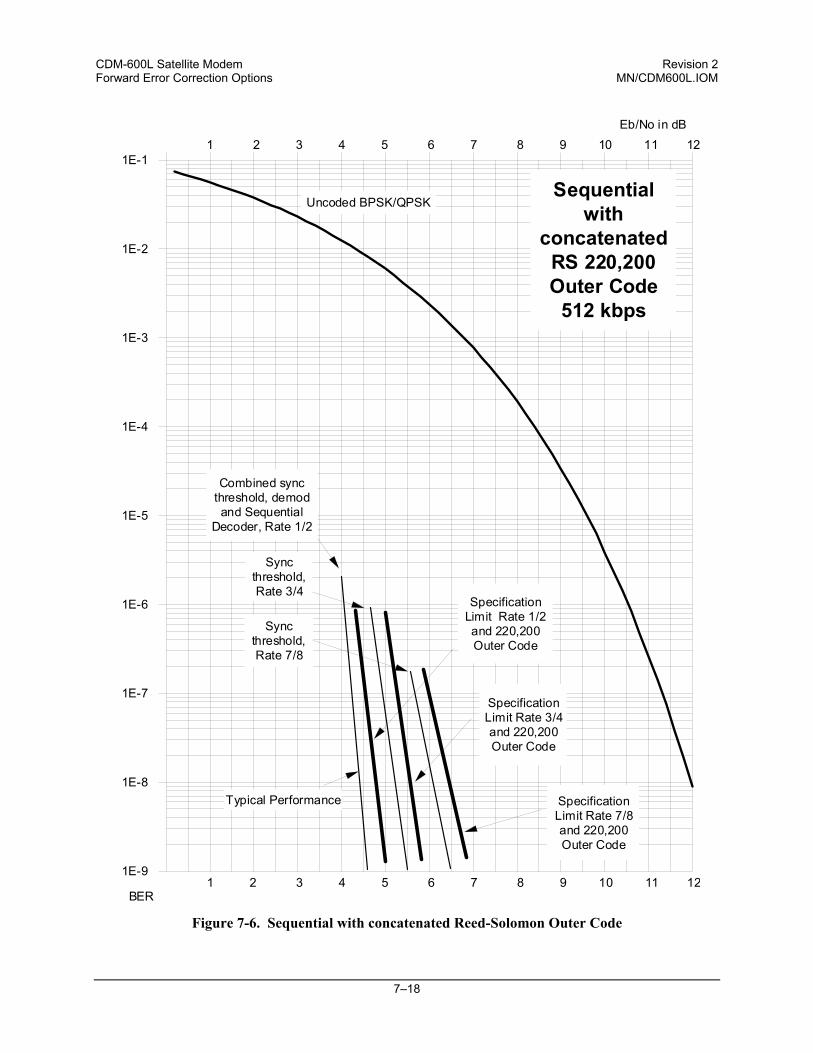
CDM-600L Satellite Modem Revision 2 Forward Error Correction Options MN/CDM600L.IOM
7–18
Figure 7-6. Sequential with concatenated Reed-Solomon Outer Code
1E-9
1E-8
1E-7
1E-6
1E-5
1E-4
1E-3
1E-2
1E-11 2 3 4 5 6 7 8 9 10 11 12
Eb/No in dB
SpecificationLimit Rate 1/2and 220,200Outer Code
Uncoded BPSK/QPSK
1 2 3 4 5 6 7 8 9 10 11 12BER
Sequentialwith
concatenatedRS 220,200Outer Code
512 kbps
Combined syncthreshold, demodand Sequential
Decoder, Rate 1/2
Syncthreshold,Rate 3/4
SpecificationLimit Rate 3/4and 220,200Outer Code
SpecificationLimit Rate 7/8and 220,200Outer Code
Syncthreshold,Rate 7/8
Typical Performance
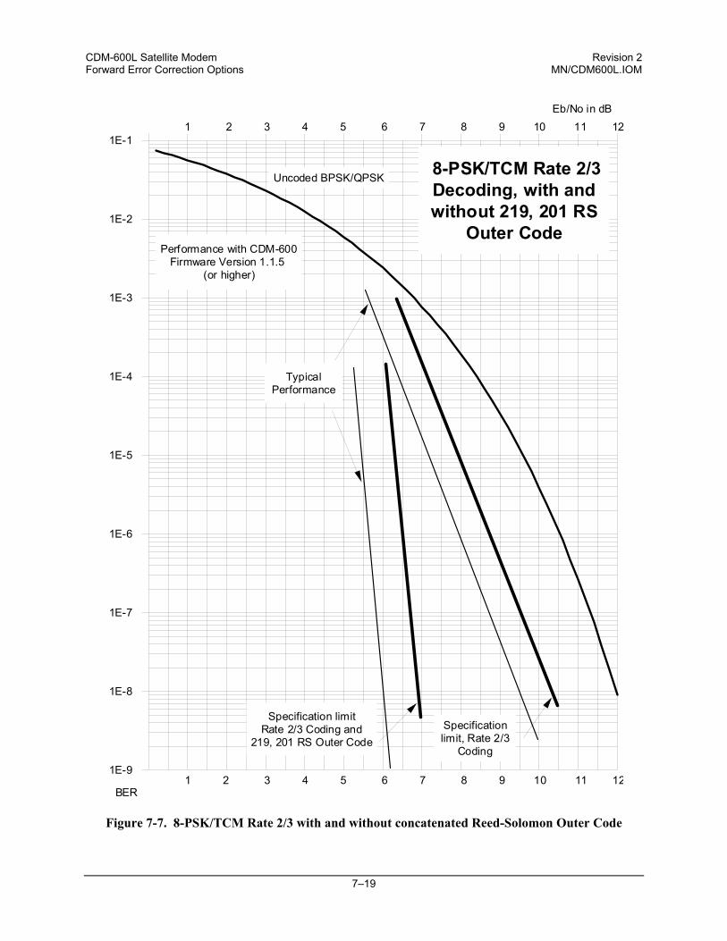
CDM-600L Satellite Modem Revision 2 Forward Error Correction Options MN/CDM600L.IOM
7–19
Figure 7-7. 8-PSK/TCM Rate 2/3 with and without concatenated Reed-Solomon Outer Code
1E-9
1E-8
1E-7
1E-6
1E-5
1E-4
1E-3
1E-2
1E-11 2 3 4 5 6 7 8 9 10 11 12
Eb/No in dB
Specification limitRate 2/3 Coding and
219, 201 RS Outer Code
Uncoded BPSK/QPSK
TypicalPerformance
Specificationlimit, Rate 2/3
Coding
1 2 3 4 5 6 7 8 9 10 11 12BER
8-PSK/TCM Rate 2/3Decoding, with andwithout 219, 201 RS
Outer CodePerformance with CDM-600
Firmware Version 1.1.5 (or higher)
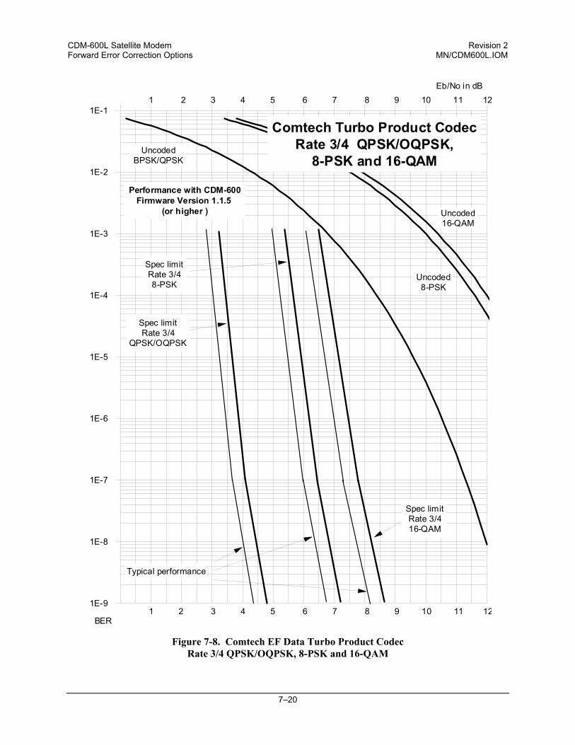
CDM-600L Satellite Modem Revision 2 Forward Error Correction Options MN/CDM600L.IOM
7–20
Figure 7-8. Comtech EF Data Turbo Product Codec Rate 3/4 QPSK/OQPSK, 8-PSK and 16-QAM
1E-9
1E-8
1E-7
1E-6
1E-5
1E-4
1E-3
1E-2
1E-11 2 3 4 5 6 7 8 9 10 11 12
Eb/No in dB
UncodedBPSK/QPSK
Comtech Turbo Product CodecRate 3/4 QPSK/OQPSK,
8-PSK and 16-QAM
1 2 3 4 5 6 7 8 9 10 11 12BER
Spec limitRate 3/416-QAM
Spec limitRate 3/48-PSK
Spec limitRate 3/4
QPSK/OQPSK
Typical performance
Uncoded8-PSK
Uncoded16-QAM
Performance with CDM-600Firmware Version 1.1.5
(or higher )
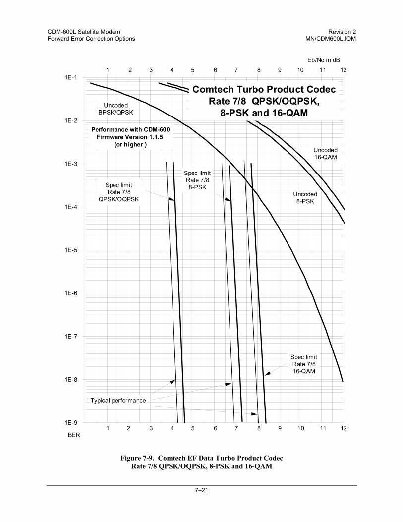
CDM-600L Satellite Modem Revision 2 Forward Error Correction Options MN/CDM600L.IOM
7–21
Figure 7-9. Comtech EF Data Turbo Product Codec Rate 7/8 QPSK/OQPSK, 8-PSK and 16-QAM
1E-9
1E-8
1E-7
1E-6
1E-5
1E-4
1E-3
1E-2
1E-11 2 3 4 5 6 7 8 9 10 11 12
Eb/No in dB
UncodedBPSK/QPSK
Comtech Turbo Product CodecRate 7/8 QPSK/OQPSK,
8-PSK and 16-QAM
1 2 3 4 5 6 7 8 9 10 11 12BER
Spec limitRate 7/816-QAM
Spec limitRate 7/88-PSKSpec limit
Rate 7/8QPSK/OQPSK
Typical performance
Uncoded8-PSK
Uncoded16-QAM
Performance with CDM-600Firmware Version 1.1.5
(or higher )
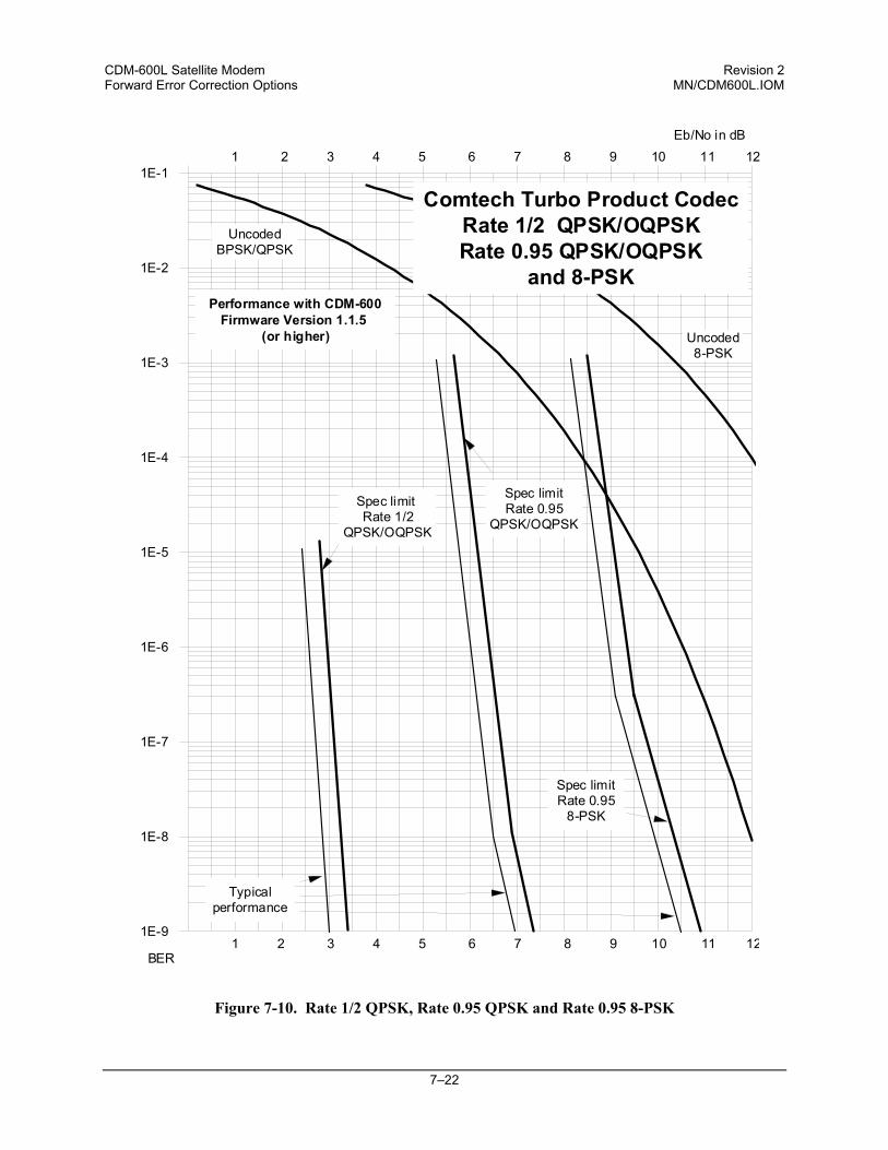
CDM-600L Satellite Modem Revision 2 Forward Error Correction Options MN/CDM600L.IOM
7–22
Figure 7-10. Rate 1/2 QPSK, Rate 0.95 QPSK and Rate 0.95 8-PSK
1E-9
1E-8
1E-7
1E-6
1E-5
1E-4
1E-3
1E-2
1E-11 2 3 4 5 6 7 8 9 10 11 12
Eb/No in dB
UncodedBPSK/QPSK
Comtech Turbo Product CodecRate 1/2 QPSK/OQPSKRate 0.95 QPSK/OQPSK
and 8-PSK
1 2 3 4 5 6 7 8 9 10 11 12BER
Spec limitRate 0.95
8-PSK
Spec limitRate 0.95
QPSK/OQPSK
Spec limit Rate 1/2
QPSK/OQPSK
Typicalperformance
Uncoded8-PSK
Performance with CDM-600Firmware Version 1.1.5
(or higher)
CDM-600L Satellite Modem Revision 2 Forward Error Correction Options MN/CDM600L.IOM
7–23
Figure 7-11. Rate 21/44 BPSK and Rate 5/16 BPSK Turbo
1E-9
1E-8
1E-7
1E-6
1E-5
1E-4
1E-3
1E-2
1E-11 2 3 4 5 6 7 8 9 10 11 12
Eb/No in dB
UncodedBPSK/QPSK
Comtech Turbo Product CodecRate 21/44 BPSKRate 5/16 BPSK
1 2 3 4 5 6 7 8 9 10 11 12BER
Spec limitRate 21/44
BPSK
Spec limitRate 5/16
BPSK
Typicalperformance
CDM-600L Satellite Modem Revision 2 Forward Error Correction Options MN/CDM600L.IOM
7–24
Figure 7-12. 16-QAM Viterbi, Rate 3/4 and Rate 7/8 with 220,200 Reed-Solomon Outer Code
1E-9
1E-8
1E-7
1E-6
1E-5
1E-4
1E-3
1E-2
1E-11 2 3 4 5 6 7 8 9 10 11 12
Eb/No in dB
Specification limit Rate3/4 Viterbi and 220,200
RS Outer Code
Uncoded BPSK/QPSK
TypicalPerformance
Specificationlimit Rate 7/8
Viterbi and220,200 RSOuter Code
1 2 3 4 5 6 7 8 9 10 11 12BER
16-QAM Viterbi, Rate 3/4 and Rate 7/8with 220,200 RS Outer Code
Uncoded 16-QAM
CDM-600L Satellite Modem Revision 2 Forward Error Correction Options MN/CDM600L.IOM
7–25
Figure 7-13. Differential Encoding - No FEC, No Scrambling
1E-9
1E-8
1E-7
1E-6
1E-5
1E-4
1E-3
1E-2
1E-11 2 3 4 5 6 7 8 9 10 11 12
Eb/No in dB
Uncoded BPSK/QPSK
DifferentialEncoding -No FEC, noscrambling
1 2 3 4 5 6 7 8 9 10 11 12BER
CDM-600L Satellite Modem Revision 2 Forward Error Correction Options MN/CDM600L.IOM
7–26
Figure 7-14. LDPC, Rate 1/2, BPSK, (O)QPSK
1E-9
1E-8
1E-7
1E-6
1E-5
1E-4
1E-3
1E-2
1E-1
BPSK/QPSK/OQPSK
BER
Spec limitRate 1/2
BPSK/QPSK/OQPSK
LDPC, BPSK, QPSK,(O)QPSK, Rate 1/2
Uncoded
Typical limitRate 1/2
BPSK/QPSK/OQPSK
Eb/No in dB1 2 3 4 5 6 7 8 9 10 11 12
1 2 3 4 5 6 7 8 9 10 11 12
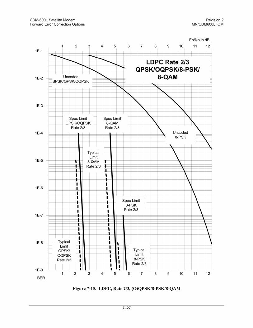
CDM-600L Satellite Modem Revision 2 Forward Error Correction Options MN/CDM600L.IOM
7–27
Figure 7-15. LDPC, Rate 2/3, (O)QPSK/8-PSK/8-QAM
1E-9
1E-8
1E-7
1E-6
1E-5
1E-4
1E-3
1E-2
1E-11 2 3 4 5 6 7 8 9 10 11 12
Eb/No in dB
1 2 3 4 5 6 7 8 9 10 11 12BER
Uncoded8-PSK
UncodedBPSK/QPSK/OQPSK
LDPC Rate 2/3QPSK/OQPSK/8-PSK/
8-QAM
Spec LimitQPSK/OQPSK
Rate 2/3
TypicalLimit
QPSK/OQPSKRate 2/3
TypicalLimit
8-QAMRate 2/3
Spec Limit8-QAM
Rate 2/3
Spec Limit8-PSK
Rate 2/3
TypicalLimit
8-PSKRate 2/3
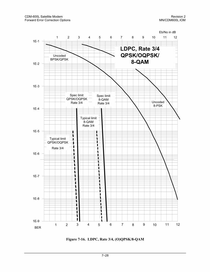
CDM-600L Satellite Modem Revision 2 Forward Error Correction Options MN/CDM600L.IOM
7–28
Figure 7-16. LDPC, Rate 3/4, (O)QPSK/8-QAM
1E-9
1E-8
1E-7
1E-6
1E-5
1E-4
1E-3
1E-2
1E-11 2 3 4 5 6 7 8 9 10 11 12
Eb/No in dB
UncodedBPSK/QPSK
BER
Spec limitQPSK/OQPSK
Rate 3/4 Uncoded8-PSK
Typical limitQPSK/OQPSK
Rate 3/4
1 2 3 4 5 6 7 8 9 10 11 12
LDPC, Rate 3/4QPSK/OQPSK/
8-QAM
Spec limit8-QAM
Rate 3/4
Typical limit8-QAM
Rate 3/4
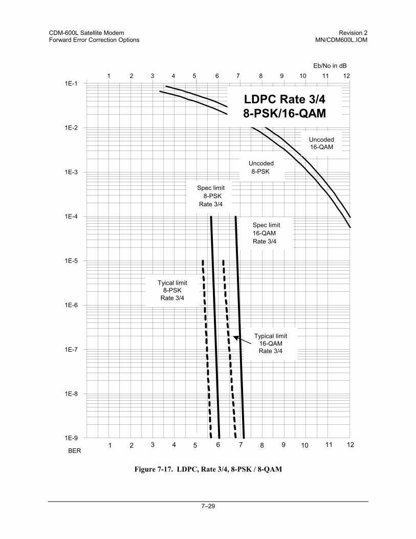
CDM-600L Satellite Modem Revision 2 Forward Error Correction Options MN/CDM600L.IOM
7–29
Figure 7-17. LDPC, Rate 3/4, 8-PSK / 8-QAM
1E-9
1E-8
1E-7
1E-6
1E-5
1E-4
1E-3
1E-2
1E-11 2 3 4 5 6 7 8 9 10 11 12
Eb/No in dB
BER
Spec limit8-PSK
Rate 3/4
Spec limit16-QAMRate 3/4
1 2 3 4 5 6 7 8 9 10 11 12
Uncoded16-QAM
Uncoded8-PSK
LDPC Rate 3/48-PSK/16-QAM
Typical limit16-QAMRate 3/4
Tyical limit8-PSK
Rate 3/4

CDM-600L Satellite Modem Revision 2 Forward Error Correction Options MN/CDM600L.IOM
7–30
NOTES:
8–1
Chapter 8. OFFSET QPSK OPERATION
Offset QPSK modulation is a variation of normal QPSK, which is offered in the CDM-600L. Normal, bandlimited, QPSK produces an RF signal envelope that necessarily goes through a point of zero amplitude when the modulator transitions through non-adjacent phase states. This is not considered to be a problem in most communication systems, as long as the entire signal processing chain is linear. However, when bandlimited QPSK is passed through a non-linearity (for instance, a saturated power amplifier), there is a tendency for the carefully-filtered spectrum to degrade. This phenomenon is termed ‘spectral re-growth’, and at the extreme (hard limiting) the original, unfiltered sin(x)/x spectrum would result. In most systems, this would cause an unacceptable level of interference to adjacent carriers, and would cause degradation of the BER performance of the corresponding demodulator. To overcome the problem of the envelope collapsing to a point of zero amplitude, Offset QPSK places a delay between I and Q channels of exactly 1/2 symbol. Now the modulator cannot transition through zero when faced with non-adjacent phase states. The result is that there is far less variation in the envelope of the signal, and non-linearities do not cause the same level of degradation. The demodulator must re-align the I and Q symbol streams before the process of carrier recovery can take place. For various reasons this makes the process of acquisition more difficult.
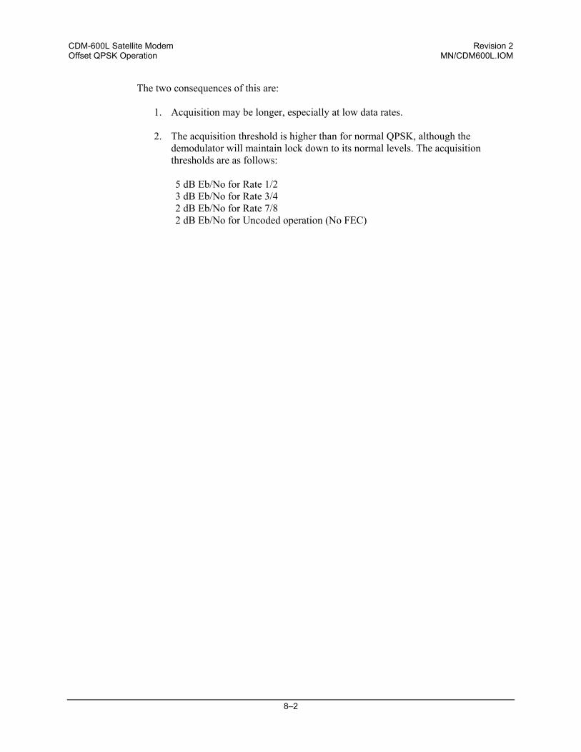
CDM-600L Satellite Modem Revision 2 Offset QPSK Operation MN/CDM600L.IOM
8–2
The two consequences of this are:
1. Acquisition may be longer, especially at low data rates.
2. The acquisition threshold is higher than for normal QPSK, although the demodulator will maintain lock down to its normal levels. The acquisition thresholds are as follows:
5 dB Eb/No for Rate 1/2 3 dB Eb/No for Rate 3/4 2 dB Eb/No for Rate 7/8 2 dB Eb/No for Uncoded operation (No FEC)
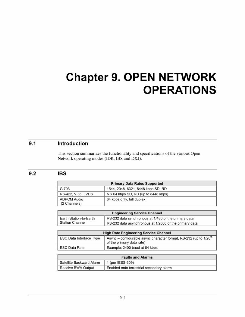
9–1
Chapter 9. OPEN NETWORK OPERATIONS
9.1 Introduction
This section summarizes the functionality and specifications of the various Open Network operating modes (IDR, IBS and D&I).
9.2 IBS
Primary Data Rates Supported G.703 1544, 2048, 6321, 8448 kbps SD, RD RS-422, V.35, LVDS N x 64 kbps SD, RD (up to 8448 kbps) ADPCM Audio (2 Channels)
64 kbps only, full duplex
Engineering Service Channel
Earth Station-to-Earth Station Channel
RS-232 data synchronous at 1/480 of the primary data RS-232 data asynchronous at 1/2000 of the primary data
High Rate Engineering Service Channel
ESC Data Interface Type Async – configurable async character format, RS-232 (up to 1/20th of the primary data rate)
ESC Data Rate Example: 2400 baud at 64 kbps
Faults and Alarms Satellite Backward Alarm 1 (per IESS-309) Receive BWA Output Enabled onto terrestrial secondary alarm
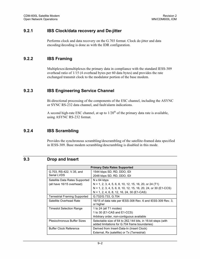
CDM-600L Satellite Modem Revision 2 Open Network Operations MN/CDM600L.IOM
9–2
9.2.1 IBS Clock/data recovery and De-jitter
Performs clock and data recovery on the G.703 format. Clock de-jitter and data encoding/decoding is done as with the IDR configuration.
9.2.2 IBS Framing
Multiplexes/demultiplexes the primary data in compliance with the standard IESS-309 overhead ratio of 1/15 (4 overhead bytes per 60 data bytes) and provides the rate exchanged transmit clock to the modulator portion of the base modem.
9.2.3 IBS Engineering Service Channel
Bi-directional processing of the components of the ESC channel, including the ASYNC or SYNC RS-232 data channel, and fault/alarm indications.
A second high-rate ESC channel, at up to 1/20th of the primary data rate is available, using ASYNC RS-232 format.
9.2.4 IBS Scrambling
Provides the synchronous scrambling/descrambling of the satellite-framed data specified in IESS-309. Base modem scrambling/descrambling is disabled in this mode.
9.3 Drop and Insert
Primary Data Rates Supported G.703, RS-422, V.35, and Serial LVDS
1544 kbps SD, RD, DDO, IDI 2048 kbps SD, RD, DDO, IDI
Satellite Data Rates Supported (all have 16/15 overhead)
N x 64 kbps N = 1, 2, 3, 4, 5, 6, 8, 10, 12, 15, 16, 20, or 24 (T1) N = 1, 2, 3, 4, 5, 6, 8, 10, 12, 15, 16, 20, 24, or 30 (E1-CCS) N = 1, 2, 4, 6, 8, 12, 16, 24, 30 (E1-CAS)
Terrestrial Framing Supported G.732/G.733, G.704 Satellite Overhead Rate 16/15 of data rate per IESS-308 Rev. 6 and IESS-309 Rev. 3,
or higher Timeslot Selection Range 1 to 24 (all T1 modes)
1 to 30 (E1-CAS and E1-CCS) Arbitrary order, non-contiguous available
Plesiochronous Buffer Sizes Selectable size of 64 to 262,144 bits, in 16-bit steps (with added limitations for G.704 frame boundaries)
Buffer Clock Reference Derived from Insert-Data-In (Insert Clock) External, Rx (satellite) or Tx (Terrestrial)
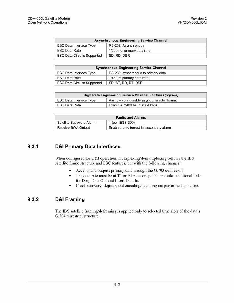
CDM-600L Satellite Modem Revision 2 Open Network Operations MN/CDM600L.IOM
9–3
Asynchronous Engineering Service Channel
ESC Data Interface Type RS-232, Asynchronous ESC Data Rate 1/2000 of primary data rate ESC Data Circuits Supported SD, RD, DSR
Synchronous Engineering Service Channel ESC Data Interface Type RS-232, synchronous to primary data ESC Data Rate 1/480 of primary data rate ESC Data Circuits Supported SD, ST, RD, RT, DSR
High Rate Engineering Service Channel (Future Upgrade) ESC Data Interface Type Async – configurable async character format ESC Data Rate Example: 2400 baud at 64 kbps
Faults and Alarms Satellite Backward Alarm 1 (per IESS-309) Receive BWA Output Enabled onto terrestrial secondary alarm
9.3.1 D&I Primary Data Interfaces
When configured for D&I operation, multiplexing/demultiplexing follows the IBS satellite frame structure and ESC features, but with the following changes:
• Accepts and outputs primary data through the G.703 connectors. • The data rate must be at T1 or E1 rates only. This includes additional links
for Drop Data Out and Insert Data In. • Clock recovery, dejitter, and encoding/decoding are performed as before.
9.3.2 D&I Framing
The IBS satellite framing/deframing is applied only to selected time slots of the data’s G.704 terrestrial structure.
CDM-600L Satellite Modem Revision 2 Open Network Operations MN/CDM600L.IOM
9–4
9.4 IDR
Primary Data Rates Supported G.703 RS-422 (Replaces 8K Overhead) V.35 (Replaces 8K Overhead)
1544 kbps SD, RD 2048 kbps SD, RD 6312 kbps SD, RD 8448 kbps SD, RD
Engineering Service Channel
ESC Audio 2 duplex ADPCM channels Audio Encoding CCITT G.721 Audio Interface Type 600Ω transformer-balanced 4-wire Audio Input Level Nominal Input : 0dBm0 (-3dBm, 600Ω)
Adjustment range: -6 to +8 dB, 2 dB steps Audio Output Level Adjustment range: -6 to +8 dB, 2 dB steps Audio Filtering Internal 300 to 3400 Hz input and output ESC Data Interface Type RS-422 ESC Data Rate 8 kbps, also 64 kbps if ADPCM audio is not used ESC Data Circuits Supported
SD, ST, RD, RT, Octet in, Octet out
Data Signal Phasing Per RS-449, data changes on the rising clock transition, is sampled on the falling clock edge
Octet Timing Octet high with every 8th bit, aligns with frame bit d8
Faults and Alarms Backward Alarms Supported 4 input, 4 output Backward Alarm Inputs 1 kΩ pull up to ground, set high to activate. Backward Alarm Outputs Form C Relay, N/O, N/C, Com
CDM-600L Satellite Modem Revision 2 Open Network Operations MN/CDM600L.IOM
9–5
9.4.1 IDR Primary Data Interfaces
When configured for IDR operation, the board performs these functions:
• Receives and performs clock and data recovery on incoming G.703 T1 and E1 pseudo-ternary data.
• Clock dejitter is performed per G.823 and G.824, and any data decoding (AMI, B8Z5, or HDB3) required per G.703 also is accomplished. IDR Framing
Multiplexes in compliance with the standard IESS-308 96 kbps ESC overhead onto the data and provides both the data and rate exchanged clock to the modulator portion of the base modem.
Performs the corresponding demultiplexing of Rx satellite data received from the demodulator portion of the modem. Resulting G.703 data is optionally encoded (AMI, B8ZS, or HDB3) before being output.
9.4.2 IDR Engineering Service Channel
Bi-directional processing of the components of the ESC channel, including the ADPCM audio channels, 8 kbps data channel, and fault indications specified by IESS-403 and IESS-308.
Option of using the ADPCM portion of the satellite overhead for a single 64 kbps ESC data channel in addition to (and with the same format as) the 8 kbps data channel.
When using G.703 format for the primary IDR data path, the P3B primary data interface (25-pin) is used for the 8kbps overhead channel. If RS-422 or V.35 is used, P3B becomes the primary interface and the 8kbps channel is unavailable.

CDM-600L Satellite Modem Revision 2 Open Network Operations MN/CDM600L.IOM
9–6
NOTES:
10–1
Chapter 10. CLOCK MODES AND DROP AND INSERT (D&I)
When dealing with satellite modems, the subject of clocking can be a complex issue. This section describes the various clocking options that are available with the CDM-600L. There are two fundamentally different interfaces provided by the modem:
• Synchronous clock and data interfaces (RS-422, V.35, etc) that permit great flexibility concerning the source and direction of clocks. These cause the most confusion.
• G.703 interfaces, in which the clock and data are combined into a single signal (and are referred to as self-clocking). In their basic form these are less flexible, and hence easier to understand. However, when used with Drop and Insert operation, the subject again becomes more complex.
10.1 Transmit Clocking
There are five transmit clocking modes in the CDM-600L. RS-422/449 signal mnemonics will be used for illustration, but the description applies equally to V.35, and synchronous RS-232.
10.1.1 Internal Clock
In this mode, the modem, assumed always to be the DCE, supplies the clock to the DTE. (The RS-422/449 name for this signal is Send Timing, or ST.) The DTE then clocks from this source, and gives the modem transmit data (Send Data, or SD), synchronous with this clock. It is optional whether the DTE also returns the clock (Terminal Timing, or TT) - the modem can accept it if it is present, but uses ST if it is not. At rates above 2 Mbps, Comtech EF Data highly recommends that the user returns TT to ensure the correct clock/data relationship. G.703: The internal clock mode does not apply – the clock is always recovered from the incoming signal, and the modem locks its modulator clocks to this.
CDM-600L Satellite Modem Revision 2 Clock Modes and Drop and Insert (D&I) MN/CDM600L.IOM
10–2
10.1.2 TX Terrestrial Clock
In this mode, the modem expects to see the DTE provide the clock, so that it can phase-lock its internal circuits. In this case, the modem does not provide any signal on ST, but instead requires a clock signal on Terminal Timing (TT), synchronous with the data. If no clock is present, an alarm will be generated and the modem will substitute its internal clock. G.703: This is the ‘natural’ clock mode.
10.1.3 RX Loop-Timed, RX=TX
In certain circumstances, a terminal at the distant-end of a satellite link may be required to provide a clock to the DTE equipment which is locked to the receive satellite signal. This is similar to Internal Clock mode, in that the modem will source Send Timing (ST) to the DTE, but now the timing is derived from the demodulator. The DTE then clocks from this source, and gives the modem transmit data (Send Data, or SD), synchronous with this clock. It is optional whether the DTE also returns the clock (Terminal Timing, or TT) - the modem can accept if it is present, but uses ST if it is not. If the demodulator loses lock, the modem’s internal clock will be substituted, so an accurate and stable clock is present on ST, rather than a clock that may jitter and wander in a random fashion. G.703: Does not apply.
10.1.4 RX Loop-Timed, RX<>TX (Asymmetric Loop Timing)
The CDM-600L incorporates circuitry which permits loop timing when the TX and RX data rates are not the same. In this case the clock frequency appearing at ST will be whatever the TX data rate is programmed to, but phase-locked to the demodulator’s receive symbol clock. In all other respects the operation is the same as for ‘standard’ loop timing. G.703: Does not apply.
10.1.5 External Clock
The modem will accept a station clock at the rear of the modem to serve as its ST clock directly. In this case, the station clock must be equal to the transmit data rate being used. Note: G.703 - Does not apply.
CDM-600L Satellite Modem Revision 2 Clock Modes and Drop and Insert (D&I) MN/CDM600L.IOM
10–3
10.1.6 External Reference
When enabled, the External Reference input is applied to a PLL that phase locks the modems internal 10 MHz reference oscillator to a 1, 2, 5, 10, or 20 MHz external reference. Unlike the External Clock input, which serves as a direct substitute for the transmit ST clock, the External Reference input becomes a reference for both the carrier synthesizers and the data clocking since the internal 10 MHz reference oscillator is phase locked to the external reference. If INTERNAL is selected for the transmit clock, and External Reference is also enabled, the ST clock will be locked to the external reference.
10.2 Receive Clocking
There are three receive clocking modes in the CDM-600L, plus an additional setting used for Drop and Insert only – see later section.
10.2.1 Buffer Disabled (RX Satellite)
When the buffer is disabled, the receive clock (Receive Timing, or RT) is derived directly from the demodulator, and hence will be subject to plesiochronous and Doppler offsets. In certain instances, this may be acceptable. There is still a minimum buffer in use to de-jitter the effects of removing overhead framing. Note: G.703 - Applicable.
10.2.2 Buffer Enabled, TX=RX (TX Terrestrial or External Clock)
In this instance, it is required that buffer be enabled, so that the clock and data appearing on Receive Timing and Receive Data (RT and RD respectively) are synchronous with the transmit clock or the external reference input. This is a relatively simple case, as the output clock for the buffer is derived directly from either ST, TT or the external source. Note: G.703 - Applicable.
10.2.3 Buffer Enabled, RX<>TX (TX Terrestrial or External Clock)
This is an uncommon case, where the receive data rate does not equal the transmit or external reference. The modem will generate a phase-locked buffer output clock which uses the selected reference, regardless of its frequency in relation to the receive data rate. Note: G.703 - Applicable.
10.3 X.21 Notes
For X.21 operation, use the RS-422 pins, but ignore Receive Clock if the Modem is DTE, and ignore Transmit clocks if the Modem is DCE.
CDM-600L Satellite Modem Revision 2 Clock Modes and Drop and Insert (D&I) MN/CDM600L.IOM
10–4
Figure 10-1 Tx Clock Modes
CDM-600L Satellite Modem Revision 2 Clock Modes and Drop and Insert (D&I) MN/CDM600L.IOM
10–5
Figure 10-2 Rx Clock Modes
CDM-600L Satellite Modem Revision 2 Clock Modes and Drop and Insert (D&I) MN/CDM600L.IOM
10–6
10.4 Drop and Insert
The Drop and Insert multiplexer works in conjunction with the G.703 interfaces to enable the modem to transmit or receive fractional parts of a T1 or E1 data stream. The D&I option provides fully compliant baseband processing in accordance with Intelsat IESS-308 for the terrestrial information rate of 2048 kbps (E1) and 1544 kbps (T1), using G.703 interfaces. The data rate sent over the satellite link is n x 64 kbps. See the Frame Formats diagram for the permissible values of n. The modem provides the interface to transmission level framing compliant to IESS-309 data type 2. Note: For Hardware Version 2.0 or higher, D&I operation is possible through the 25-pin data port in either RS-422 or V.35 format. If used, the DDO/IDI ‘inner loop’ is not available. For Firmware Version 1.2.0 or higher, D&I operation can also be done using the proprietary D&I++ framing mode.
10.5 Frame Formats
The E1 and T1 frame formats that are supported are shown in the Figure below:
1 2 3 4 5 6 7 8 9 10 11 12 13 14 15 16 17 18 19 20 21 22 23 24 25 26 27 28 29 300 1 2 3 4 5 6 7 8 9 10 11 12 13 14 15 16 17 18 19 20 21 22 23 24 25 26 27 28 29 30 31
1 2 3 4 5 6 7 8 9 10 11 12 13 14 15 16 17 18 19 20 21 22 23 24 25 26 27 28 29 300 1 2 3 4 5 6 7 8 9 10 11 12 13 14 15 16 17 18 19 20 21 22 23 24 25 26 27 28 29 30 31
1 2 3 4 5 6 7 8 9 10 11 12 13 14 15 16 17 18 19 20 21 22 23 241 2 3 4 5 6 7 8 9 10 11 12 13 14 15 16 17 18 19 20 21 22 23 24
1 2 3 4 5 6 7 8 9 10 11 12 13 14 15 16 17 18 19 20 21 22 23 241 2 3 4 5 6 7 8 9 10 11 12 13 14 15 16 17 18 19 20 21 22 23 24
E1-CCS (Common Channel Signalling) 2048 kbps E1 Frame Maximum channels to drop = 30 = 1920 kbps n x 64 kbps, n = 1,2,3,4,5,6,8,10,12,15,16,20,24,30
TimeSlotNo.
TimeSlotNo.
Reserved forFraming
Reserved forFraming
May be reserved for Signalling. All signalling information is common to all 30 TS and no signalling is transmitted.
Reserved for Signalling. All signalling is transmitted for TS's dropped in IBS overhead (500Hz per TS) Signalling information in TS 16 is associated to specific TS's.
E1-CAS (Channel Associated Signalling) 2048 kbps E1 Frame Maximum channels to drop = 30 = 1920 kbps n x 64 kbps, n = 1,2,4,6,8,12,16,24,30
TimeSlotNo.
TimeSlotNo.
T1-D4 (D4 Framing) 1544 kbps T1 Frame 12-Frame multi-frame structure. No IBS multi-frame signalling will be transmitted. Maximum channels to drop = 24 = 1536 kbps n x 64 kbps, n = 1,2,3,4,5,6,8,10,12,15,16,20,24
T1-ESF (Extended Super Frame) 1544 kbps T1 Frame 24-Frame multi-frame structure. No IBS multi-frame signalling will be transmitted. Maximum channels to drop = 24 = 1536 kbps n x 64 kbps, n = 1,2,3,4,5,6,8,10,12,15,16,20,24
Figure 10-3 Supported T1 and E1 Framing Formats
CDM-600L Satellite Modem Revision 2 Clock Modes and Drop and Insert (D&I) MN/CDM600L.IOM
10–7
10.6 Time Slot Selection
Selection of the transmit and receive data rates may be made in certain 64 kbps increments and may be independent of each other. The actual satellite rates for open network D&I are 16/15 of the transmit or receive data rate to include IBS overhead per IESS-309, although this is transparent to the user. For E1, the user can select any time slot (TS) from 1 to 31. Selection of TS 0 is not permitted. For T1, the user can select any time slot (TS) from 1 to 24. The user may also select “N/A” to leave a satellite channel unused. The configuration menu allows time slots to be selected for transmission or reception up to the maximum dictated by the selected transmit or receive data rate, and may be selected in arbitrary order. As an example, if the data rate is set to 256 kbps, the maximum number of time slots that can be dropped or inserted is 4 (being 4 x 64 kbps). Note that for 1920 kbps data rate the timeslots may not be manipulated. This is the ‘fixed channel’ mode where Timeslot 1 is assigned to Channel 1, and so on. For D&I++ framing, all increments of 64 kbps are allowed up to a maximum of 24 (1536 kbps). For this mode, the satellite rate is 46/45 of the front panel data rate (2.22%).
CDM-600L Satellite Modem Revision 2 Clock Modes and Drop and Insert (D&I) MN/CDM600L.IOM
10–8
10.7 Drop and Insert Clocking
The general arrangement for Drop and Insert clocking in the CDM-600L is shown below:
Figure 10-4 Drop and Insert Clocking
Note that are two inputs and two outputs shown for Drop and Insert Operation. These are:
• Drop Data In (DDI) • Drop Data Out (DDO)
• Insert Data In (IDI) • Insert Data Out (IDO)
This arrangement permits the user to choose between fully independent operation of the incoming and outgoing E1/T1 signal, or to use the same T1/E1 signal for both Dropping and Inserting (looped mode). If ‘Loop’ has been selected under the Drop and Insert configuration menu, the Drop Data Out (DDO) signal is automatically looped internally, to become the Insert Data In (IDI). In this mode, timeslots are dropped from an incoming E1/T1 signal for transmission over the satellite, and the same E1/T1 signal has time slots re-inserted into it that will over-write data in existing timeslots.
CDM-600L Satellite Modem Revision 2 Clock Modes and Drop and Insert (D&I) MN/CDM600L.IOM
10–9
10.8 Rx Buffer Clock = Insert (D&I only)
The E1 or T1 clock recovery from the IDI G.703 port serves as the Rx Buffer reference. In addition, the recovered data is the E1/T1 input to the Insert Mux. If the Rx G.703 recovery circuit detects no activity at IDI input, or cannot detect the expected frame format, Buffer Clock = Rx Satellite will be chosen as a fall-back. If ‘Insert’ is not the selected buffer clock reference, the clock and data from the IDI port is ignored, and a new E1/T1 frame is generated. The time slots coming from the satellite are then re-inserted into the selected timeslots of this new blank frame, and output on the IDO port.
10.9 Single-Source Multiple Modems
Two ways to connect a single T1 or E1 stream to several modems are by looming or daisy-chaining modems. Each method is illustrated in Figure 10-5 for Looming and Figure 10-6 for daisy chain and each requires the RX Buffer Clock = Insert setting.
• Assign all timeslots to not overlap. • Assign modems to number of TX/RX channels as required.
CDM-600L Satellite Modem Revision 2 Clock Modes and Drop and Insert (D&I) MN/CDM600L.IOM
10–10
BIT ERROR TEST
IDO
(RX)
IDI(L
OO
P)
DD
O(L
OO
P)
DD
I(TX)
IDO
(RX)
IDO
(RX
)
IDI(L
OO
P)
IDI(L
OO
P)
DD
O(L
OO
P)
DD
O(L
OO
P)
DD
I(TX)
DD
I(TX)
Figure 10-5. Single-Source Multiple Modems (Looming)
DDI DDO
IDI
IDO
MODEM MODEM MODEM
Terrestrial TrunkMultiple Modem Drop & Insert Application: This application shows how the loop is extendedto one or more additional modems.
DDO- IDI connection may be made internally using Loop = Y under D&I menu.
IDI
Figure 10-6. Single-Source Multiple Modems (Daisy Chain)
- - - - - - - - - - Receive ___________ Transmit
11–1
Chapter 11. EDMAC CHANNEL
11.1 Theory Of Operation
As explained earlier, EDMAC is an acronym for Embedded Distant-end Monitor And Control. This is a feature which permits the user to access the M&C features of modems which are at the distant-end of a satellite link. This is accomplished by adding extra information to the user’s data, but in a manner which is completely transparent to the user.
On the transmit side: The data is split into frames - each frame containing 1008 bits (except Rate 21/44 BPSK Turbo, or when the data rates exceed 2048 kbps, where the frame length is 2928 bits, and Rate 5/16 BPSK Turbo where the frame length is 3072 bits). 48 bits in each frame are overhead, and the rest of these bits are the user’s data. This increases the rate of transmission by 5% (approximately 1.5% for the Turbo BPSK cases, and for all data rates greater than 2.048 Mbps). For example, if the user’s data rate is 64 kbps, the actual transmission rate will now be at 67.2 kbps. At the start of each frame a 12 bit synchronization word is added. This allows the demodulator to find and lock to the start of frame. At regular intervals throughout the frame, additional data bytes and flag bits are added (a further 36 bits in total). It is these additional bytes which convey the M&C data. When framing is used, the normal V.35 scrambler is no longer used. This V.35 approach is called ‘self synchronizing’, because in the receiver, no external information is required in order for the de-scrambling process to recover the original data. The disadvantage of this method is that it multiplies errors. On average, if one bit error is present at the input of the descrambler, 3 output errors are generated. However, there is an alternative when the data is in a framed format. In this case, a different class of scrambler may be used - one which uses the start of frame information to start the scrambling process at an exact
CDM-600L Satellite Modem Revision 2 EDMAC Channel MN/CDM600L.IOM
11–2
known state. In the receiver, having synchronised to the frame, the de-scrambler can begin its processing at exactly the right time. This method does not multiply errors, and therefore has a clear advantage over V.35 scrambling. This is fortunate, as there is a penalty to be paid for adding the framing. By adding the extra 5% to the transmitted data rate, the effective Eb/No seen by the user will degrade by a factor of 10log (1.05), or 0.21 dB (0.07dB in the case of the two BPSK Turbo rates). The use of an externally synchronized scrambler and descrambler almost exactly compensates for this degradation. The net effect is that the user will see effectively identical BER performance whether framing is used or not.
On the receive side: When the demodulator locks to the incoming carrier, it must go through the additional step of searching for, and locking to the synchronization word. This uniquely identifies the start of frame, and permits the extraction of the overhead bytes and flag bits at the correct position within the frame. In addition, the start of frame permits the de-scrambler to correctly recover the data. The user’s data is extracted, and sent through additional processing, in the normal manner. The extracted overhead bytes are examined to determine if they contain valid M&C bytes.
11.2 M&C Connection
Data to be transmitted to the distant-end is sent to a local unit via the remote control port. A message for the distant-end is indistinguishable from a ‘local’ message - it has the same structure and content, only the address will identify it as being for a distant-end unit. Before the M&C data can be successfully transmitted and received, pairs of units must be split into EDMAC Masters and EDMAC Slaves. Masters are local to the M&C Computer, and Slaves are distant-end. Now, a unit which has been designated an EDMAC master not only responds to its own unique bus address, but it will also be configured to listen for the address which corresponds to its EDMAC Slave. When a complete message packet has been received by the EDMAC Master, it will begin to transmit this packet over the satellite channel, using the overhead bytes which become available. Note: The ‘normal’ protocol for the message packet is not used over the satellite path, as it is subject to errors. For this reason, a much more robust protocol is used which incorporates extensive error checking. At the distant-end, the EDMAC slave, configured for the correct address, receives these bytes, and when a complete packet has been received, it will take the action requested, and then send the appropriate response to the EDMAC Master, using the return overhead path on the satellite link. The EDMAC Master assembles the complete packet, and transmits the response back to the M&C Computer.
CDM-600L Satellite Modem Revision 2 EDMAC Channel MN/CDM600L.IOM
11–3
Apart from the round-trip satellite delay, the M&C Computer does not see any difference between local and distant-end units - it sends out a packet, addressed to a particular unit, and gets back a response. It can be seen that the EDMAC Master simply acts as forwarding service, in a manner which is completely transparent. This approach does not require any additional cabling - connection is made using the normal M&C remote port. Furthermore, the user does not have to worry about configuring the baud rate of the M&C connection to match the lowest data rate modem in the system. The M&C system can have mixed data-rate modems, from 2.4 kbps to 2048 kbps, and still run at speeds in excess of 19,200 baud. It should be pointed out that at 2.4 kbps, the effective throughput of the overhead channel is only 11 async characters/second. For a message of 24 bytes, the time between sending a poll request and receiving a response will be around 5 seconds. (Note that when either of the BPSK Turbo rates are in use, the overhead rate is reduced by a factor of three, and therefore the response time will be around 15 seconds.)
11.3 Setup Summary
To access a distant-end unit:
Designate a Master/Slave pair - Master at the local-end, Slave at the distant-end.
On the local-end unit, enable framing, and EDMAC, define the unit as MASTER, then enter the bus address. This is constrained to be ‘base 10' meaning that only addresses such as 10, 20, 30, 40 etc, are allowed.
Choose a unique bus address for the distant-end. This should normally be set to
the ‘base 10' address + 1. For example, if the MASTER unit is set to 30, choose 31 for the distant-end unit.
On the distant-end unit, enable framing, and EDMAC, define the unit as SLAVE,
then enter the bus address. The orange EDMAC Mode LED should be illuminated.
Set the local-end unit to RS485 remote control, and set the bus address of this
local unit. The orange Remote Mode LED should be illuminated.
Once the satellite link has been established, connect the M&C Computer, and begin communications, with both the local and distant end units.
NOTE: EDMAC modes are fully compatible with AUPC modes.
CDM-600L Satellite Modem Revision 2 EDMAC Channel MN/CDM600L.IOM
11–4
11.4 Drop & Insert ++
A new variation of EDMAC is available with D&I++ framing. With this, each frame contains 2944 bits, with 64 overhead bits and 2880 user data bits. The portion of the overhead used for the EDMAC link performs identically to that of the EDMAC frame, but because D&I++ uses a smaller overhead, the two modes are not compatible with each other.
12–1
Chapter 12. AUTOMATIC UPLINK POWER CONTROL
12.1 Introduction
Automatic Uplink Power Control (AUPC) is a feature whereby a local modem is permitted to adjust its own output power level in order to attempt to maintain the Eb/No at the remote modem.
WARNING
The user SHALL obtain permission from the Satellite Operator to use this feature. Improper use of this feature could result in a transmitting terminal seriously exceeding its allocated flux density on the Operator’s satellite. This could produce interference to other carriers, and could cause transponder saturation problems
To accomplish this, the EDMAC, D&I++ or ESC++ framing types may be used. The remote modem constantly sends back information about the demodulator Eb/No using reserved bytes in the overhead structure. The local modem then compares this value of Eb/No with a pre-defined target value. If the Remote Eb/No is below the target, the local modem will increase its output power, and hence, a closed-loop feedback system is created over the satellite link. A particularly attractive benefit of this feature is that whenever framed operation is selected, the remote demodulator’s Eb/No can be viewed from the front panel display of the local modem. There are several important parameters associated with this mode of operation, and the user needs to understand how the AUPC feature works, and the implications of setting these parameters.
CDM-600L Satellite Modem Revision 2 Automatic Uplink Power Control (AUPC) MN/CDM600L.IOM
12–2
12.2 Setting AUPC Parameters
1. The user, under the menu (CONFIG, MODE) first ensures that the framing type is EDMAC, D&I++ or ESC++. (EDMAC may be configured as IDLE, or the unit may be defined as an EDMAC Master or Slave.)
2. The user should verify that the remote modem is correespondingly configured for EDMAC, D&I++ or ESC++ framing.
3. The user, under the menu (CONFIG, TX, POWER) sets the nominal output power of the modem. This is done by selecting the MANUAL mode, then editing the TX output power level displayed.
4. The user will then select AUPC as the operating mode. At this point the user will be prompted to define four key parameters:
12.2.1 AUPC Target Eb/No
This is value of Eb/No that the user desires to keep constant at the remote modem. If the Eb/No exceeds this value, the AUPC control will reduce the TX output power, but will never drop below the nominal value set. If the Eb/No falls below this value, the AUPC control will increase the TX output power, but will never exceed the value determined by the parameter MAX RANGE.
• The minimum value the user can enter is 0.0 dB • The maximum value the user can enter is 9.9 dB • The default value is 3.0 dB • The resolution is 0.1 dB
12.2.2 Max Range, AUPC
This defines how much the modem is permitted to increase the output level, under AUPC control.
• The minimum value the user can enter is 0 dB • The maximum value the user can enter is 9 dB • The default value is 1 dB • The resolution is 1 dB
CDM-600L Satellite Modem Revision 2 Automatic Uplink Power Control (AUPC) MN/CDM600L.IOM
12–3
12.2.3 Alarm, AUPC
This parameter defines how the user wants the modem to act if, under AUPC control, the maximum power limit is reached. The two choices are:
• NONE (no action) • TX ALARM (generate a Tx alarm)
The default setting is NONE.
12.2.4 Demod Unlock
This defines the action the modem will take if the remote demodulator loses lock. The two choices are:
• NOMINAL (reduce the Tx Output Power to the nominal value) • MAXIMUM (increase the Tx Output Power to the maximum value permitted by
the parameter MAX RANGE) The default setting is NOMINAL. (Note that if the local demod loses lock, the modem will automatically move its output power to the nominal value.)
12.3 Compensation Rate
As with any closed-loop control system, the loop parameters must be chosen to ensure stability at all times. Several features have been incorporated to ensure that the AUPC system does overshoot, or oscillate. First, the rate at which corrections to the output power can be made is fixed at once every 4 seconds. This takes into account the round trip delay over the satellite link, the time taken for a power change to be reflected in the remote demodulator’s value of Eb/No, and other processing delays in the modems. Second, if the comparison of actual and target Eb/No yields a result that requires a change in output power, the first correction made will be 80% of the calculated step. This avoids the possibility of overshoot. Subsequent corrections are made until the difference is less than 0.5 dB. At this point, the output power is only changed in increments of 0.1 dB, to avoid ‘hunting’ around the correct set point.
CDM-600L Satellite Modem Revision 2 Automatic Uplink Power Control (AUPC) MN/CDM600L.IOM
12–4
12.4 Monitoring
The remote demodulator’s value of Eb/No can be monitored at all times, either from the front panel (MONITOR, AUPC) or via the remote control interface. The resolution of the reading is 0.2 dB. For all values greater than or equal to 16 dB, the value 16.0 dB will be displayed. As long as framing is enabled, the value will still be available, even though AUPC may be disabled. Also displayed is the current value of Tx power increase. If EDMAC, D&I++ or ESC++ framing is enabled, but AUPC is disabled, this will indicate 0.0 dB. This value is also available via the remote control interface.
CAUTION
Comtech EF Data strongly cautions against the use of large values of permitted power level increase under AUPC control. Users should consider using the absolute minimum range necessary to improve rain-fade margin
13–1
Chapter 13. ESC++
13.1 Introduction
The ESC++ mode of operation is a new, closed network frame structure which combines Automatic Uplink Power Control (AUPC) with a high speed asynchronous order-wire channel. The AUPC works identically to that offered with EDMAC and D&I++ framing, but is not compatible with either. This is because ESC++ framing uses a different overhead percentage than the other closed network framing modes. In order to use this feature, Firmware Version 1.3.0 (or higher) must be installed.
13.2 Overhead Details
Baud rates from 1200 to 38400 bits/sec are offered using RS-232 format. As with the main remote port (P4B), three data formats are available: 8N1, 7E2 and 7O2. Pins 5 and 6 of P3A are the input and output, respectively, for this data channel. Because 38.4 kbaud is the maximum rate available, the actual overhead percentage for ESC++ framing changes as the data rate increases, thereby saving bandwidth at high data rates. The added overhead is as follows: Data rate Overhead ratio (percentage) 64 kbps to < 768 kbps 19/17 (11.76%) 768 kbps to 1.5 Mbps 12/11 (9.09%) > 1.5 Mbps to 2.5 Mbps 29/27 (7.4%) > 2.5 Mbps to 7 Mbps 19/18 (5.56%) > 7 Mbps 64/63 (1.58%)
Note that 64 kbps is the minimum data rate allowable with ESC++. Depending upon code rate and modulation used, the modem’s maximum data rate of 20 Mbps may be used with ESC++. In all cases, if the Reed-Solomon outer codec is used, the 126/112 ratio is employed with ESC++. The new frame structure may be used with any FEC codec type available with the CDM-600L.
CDM-600L Satellite Modem Revision 2 ESC++ MN/CDM600L.IOM
13–2
13.3 Available Baud Rates
At the lowest data rates, the 11.76% overhead may not allow all baud rates. The following table shows available rates: Data rate Baud rates available 64 to 127.999 kbps 1200, 2400, 4800 128 to 191.999 kbps 1200 to 9600 192 to 255.999 kbps 1200 to 14400 256 to 383.999 kbps 1200 to 19200 384 to 511.999 kbps 1200 to 28800 512 kbps and above 1200 to 38400
13.4 Configuration
To use this mode, the user should select ESC++ from the CONFIG, MODE menu. The baud rate and async character format are then selected from the CONFIG, MISC, HIGH-RATE-ESC menu. This is described in Chapter 6 (Front Panel Operations).
13.5 Effect on Eb/No performance
Because, particularly at lower data rates, where the percentage overhead is large, the increase in transmitted data rate will cause a decrease in the Eb/No performance. Therefore, all of the published data concerning BER versus Eb/No needs to be modified according to the table below: Data rate Overhead ratio (percentage) Eb/No degradation 64 kbps to < 768 kbps 19/17 (11.76%) 0.48 dB 768 kbps to 1.5 Mbps 12/11 (9.09%) 0.38 dB > 1.5 Mbps to 2.5 Mbps 29/27 (7.4%) 0.31 dB > 2.5 Mbps to 7 Mbps 19/18 (5.56%) 0.23 dB > 7 Mbps 64/63 (1.58%) 0.07 dB The degradation is simply 10 * log (Overhead ratio) The Eb/No displayed by the modem (MONITOR, RX-PARAMETERS) takes this into account in the value that is calculated.
14–1
Chapter 14. FLASH UPGRADING
The CDM-600L eliminates the need for updating firmware by physically replacing EPROMs. Instead, the CDM-600L modem uses ‘flash memory’ technology internally, and new firmware can be uploaded to the unit from an external PC, as follows:
• Go to: http://www.comtechefdata.com/ • Click on: downloads • Click on: flash upgrades
This makes software upgrading very simple, and updates can now be sent via the Internet, E-mail, or on disk. The upgrade can be performed without opening the unit, by simply connecting the modem to the serial port of a computer. The cable to connect the PC to the modem is the same as is used for normal RS-232 remote control, and comprises 3-wires between 9 pin ‘D’ type female connectors. This is shown in Appendix A. Comtech EF Data will distribute a free software utility, that is designed to run under Windows 95/98 or Windows NT. This utility program is called 600Flash.exe, and should be copied to the user’s computer hard disk. Along with this, the user will receive the latest firmware file (for example, F1451D.ccc), which the user should copy to the same sub-directory (folder). If the modem is in any sort of redundancy system, the 25-pin data connector must be disconnected before flash uploading. The user then connects the modem remote control port to an unused serial port on the user’s computer, and executes the program. The user should follow the instructions presented on the screen, and the upload will take place automatically. Following the successful upload process, the modem will automatically re-start, running the new version of firmware. During this process, the non-volatile RAM, storing the configuration of the modem, will be erased, so the user is then required to re-enter the desired configuration parameters.
CDM-600L Satellite Modem Revision 2 Flash Upgrading MN/CDM600L.IOM
14–2
Full on-line help is provided with 600Flash.exe, but if users experience a problem, or have a question, they should contact Comtech EF Data Customer Support.
WARNING
The Remote Control port RS-232 lines used for Flash upgrading are also connected to the Primary 25-pin data connector (P3B), and are used when 1:N Redundancy Switch is connected. Please ensure that NOTHING is connected to P3B pins 4, 21 and 22 – if these pins are used, the RS-232 remote control port will not function, and Flash upgrading will be impossible.
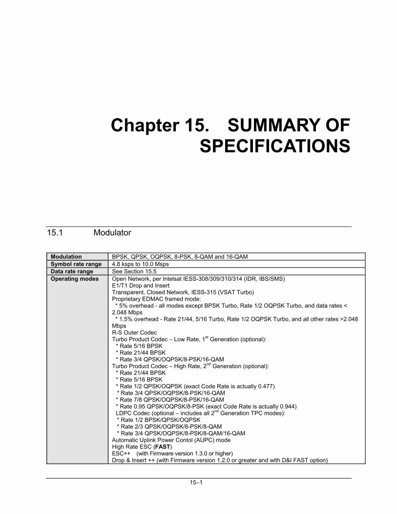
15–1
Chapter 15. SUMMARY OF SPECIFICATIONS
15.1 Modulator
Modulation BPSK, QPSK, OQPSK, 8-PSK, 8-QAM and 16-QAM Symbol rate range 4.8 ksps to 10.0 Msps Data rate range See Section 15.5 Operating modes Open Network, per Intelsat IESS-308/309/310/314 (IDR, IBS/SMS)
E1/T1 Drop and Insert Transparent, Closed Network, IESS-315 (VSAT Turbo) Proprietary EDMAC framed mode: * 5% overhead - all modes except BPSK Turbo, Rate 1/2 OQPSK Turbo, and data rates < 2.048 Mbps * 1.5% overhead - Rate 21/44, 5/16 Turbo, Rate 1/2 OQPSK Turbo, and all other rates >2.048 Mbps R-S Outer Codec Turbo Product Codec – Low Rate, 1st Generation (optional):
* Rate 5/16 BPSK * Rate 21/44 BPSK * Rate 3/4 QPSK/OQPSK/8-PSK/16-QAM
Turbo Product Codec – High Rate, 2nd Generation (optional): * Rate 21/44 BPSK * Rate 5/16 BPSK * Rate 1/2 QPSK/OQPSK (exact Code Rate is actually 0.477)
* Rate 3/4 QPSK/OQPSK/8-PSK/16-QAM * Rate 7/8 QPSK/OQPSK/8-PSK/16-QAM * Rate 0.95 QPSK/OQPSK/8-PSK (exact Code Rate is actually 0.944) LDPC Codec (optional – includes all 2nd Generation TPC modes):
* Rate 1/2 BPSK/QPSK/OQPSK * Rate 2/3 QPSK/OQPSK/8-PSK/8-QAM * Rate 3/4 QPSK/OQPSK/8-PSK/8-QAM/16-QAM Automatic Uplink Power Contol (AUPC) mode High Rate ESC (FAST) ESC++ (with Firmware version 1.3.0 or higher) Drop & Insert ++ (with Firmware version 1.2.0 or greater and with D&I FAST option)
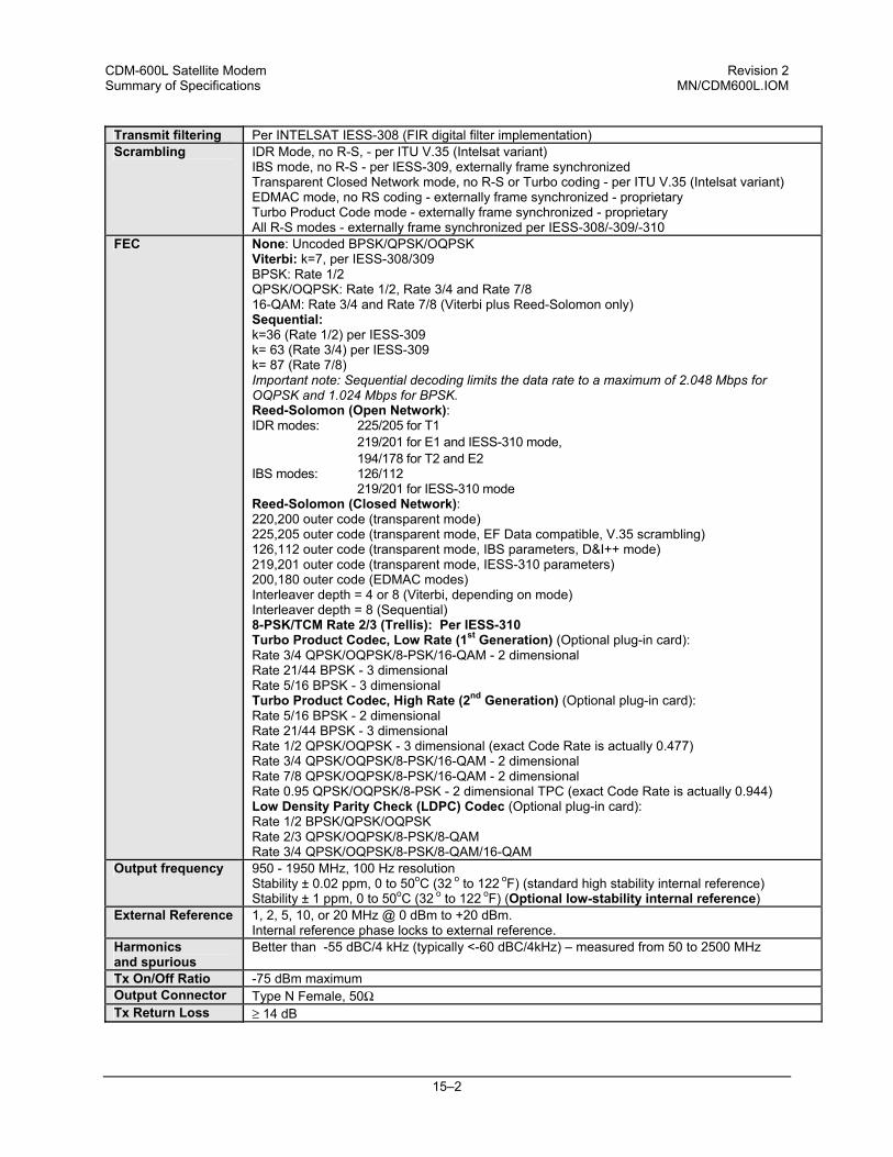
CDM-600L Satellite Modem Revision 2 Summary of Specifications MN/CDM600L.IOM
15–2
Transmit filtering Per INTELSAT IESS-308 (FIR digital filter implementation) Scrambling IDR Mode, no R-S, - per ITU V.35 (Intelsat variant)
IBS mode, no R-S - per IESS-309, externally frame synchronized Transparent Closed Network mode, no R-S or Turbo coding - per ITU V.35 (Intelsat variant) EDMAC mode, no RS coding - externally frame synchronized - proprietary Turbo Product Code mode - externally frame synchronized - proprietary All R-S modes - externally frame synchronized per IESS-308/-309/-310
FEC None: Uncoded BPSK/QPSK/OQPSK Viterbi: k=7, per IESS-308/309 BPSK: Rate 1/2 QPSK/OQPSK: Rate 1/2, Rate 3/4 and Rate 7/8 16-QAM: Rate 3/4 and Rate 7/8 (Viterbi plus Reed-Solomon only) Sequential: k=36 (Rate 1/2) per IESS-309 k= 63 (Rate 3/4) per IESS-309 k= 87 (Rate 7/8) Important note: Sequential decoding limits the data rate to a maximum of 2.048 Mbps for OQPSK and 1.024 Mbps for BPSK. Reed-Solomon (Open Network): IDR modes: 225/205 for T1 219/201 for E1 and IESS-310 mode, 194/178 for T2 and E2 IBS modes: 126/112 219/201 for IESS-310 mode Reed-Solomon (Closed Network): 220,200 outer code (transparent mode) 225,205 outer code (transparent mode, EF Data compatible, V.35 scrambling) 126,112 outer code (transparent mode, IBS parameters, D&I++ mode) 219,201 outer code (transparent mode, IESS-310 parameters) 200,180 outer code (EDMAC modes) Interleaver depth = 4 or 8 (Viterbi, depending on mode) Interleaver depth = 8 (Sequential) 8-PSK/TCM Rate 2/3 (Trellis): Per IESS-310 Turbo Product Codec, Low Rate (1st Generation) (Optional plug-in card): Rate 3/4 QPSK/OQPSK/8-PSK/16-QAM - 2 dimensional Rate 21/44 BPSK - 3 dimensional Rate 5/16 BPSK - 3 dimensional Turbo Product Codec, High Rate (2nd Generation) (Optional plug-in card): Rate 5/16 BPSK - 2 dimensional Rate 21/44 BPSK - 3 dimensional Rate 1/2 QPSK/OQPSK - 3 dimensional (exact Code Rate is actually 0.477) Rate 3/4 QPSK/OQPSK/8-PSK/16-QAM - 2 dimensional Rate 7/8 QPSK/OQPSK/8-PSK/16-QAM - 2 dimensional Rate 0.95 QPSK/OQPSK/8-PSK - 2 dimensional TPC (exact Code Rate is actually 0.944) Low Density Parity Check (LDPC) Codec (Optional plug-in card): Rate 1/2 BPSK/QPSK/OQPSK Rate 2/3 QPSK/OQPSK/8-PSK/8-QAM Rate 3/4 QPSK/OQPSK/8-PSK/8-QAM/16-QAM
Output frequency 950 - 1950 MHz, 100 Hz resolution Stability ± 0.02 ppm, 0 to 50oC (32 o to 122 oF) (standard high stability internal reference) Stability ± 1 ppm, 0 to 50oC (32 o to 122 oF) (Optional low-stability internal reference)
External Reference 1, 2, 5, 10, or 20 MHz @ 0 dBm to +20 dBm. Internal reference phase locks to external reference.
Harmonics and spurious
Better than -55 dBC/4 kHz (typically <-60 dBC/4kHz) – measured from 50 to 2500 MHz
Tx On/Off Ratio -75 dBm maximum Output Connector Type N Female, 50Ω Tx Return Loss ≥ 14 dB
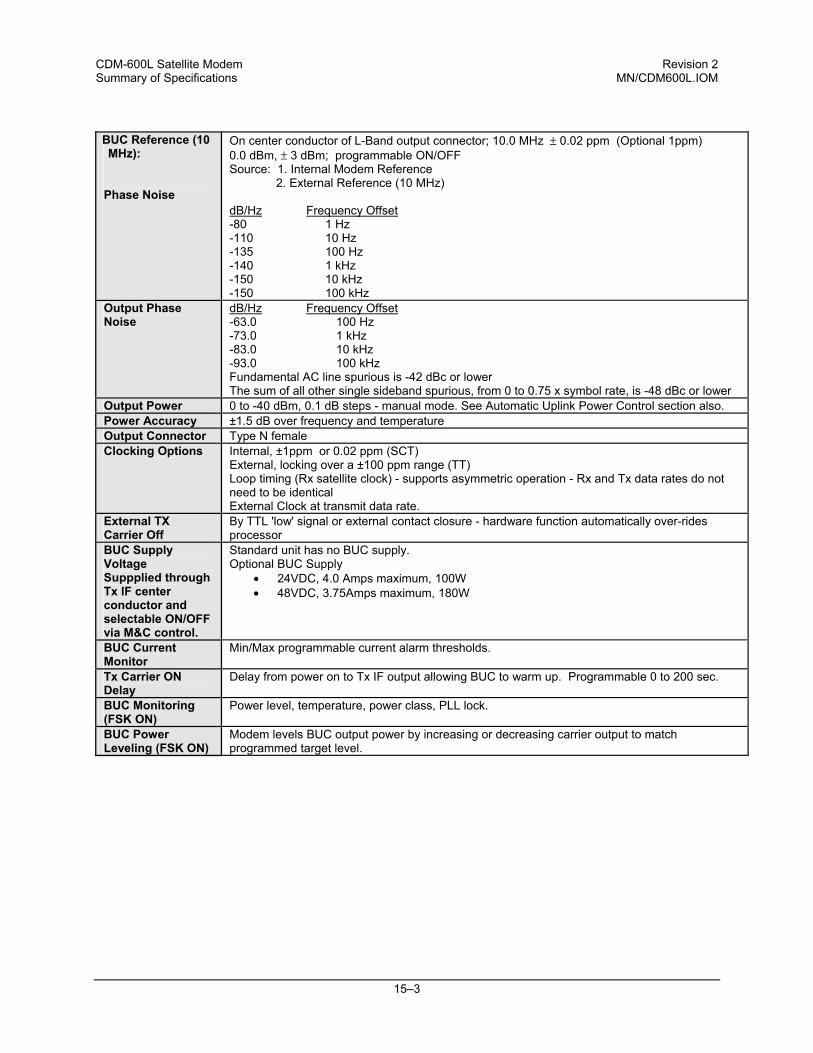
CDM-600L Satellite Modem Revision 2 Summary of Specifications MN/CDM600L.IOM
15–3
BUC Reference (10 MHz):
Phase Noise
On center conductor of L-Band output connector; 10.0 MHz ± 0.02 ppm (Optional 1ppm) 0.0 dBm, ± 3 dBm; programmable ON/OFF Source: 1. Internal Modem Reference 2. External Reference (10 MHz) dB/Hz Frequency Offset -80 1 Hz -110 10 Hz -135 100 Hz -140 1 kHz -150 10 kHz -150 100 kHz
Output Phase Noise
dB/Hz Frequency Offset -63.0 100 Hz -73.0 1 kHz -83.0 10 kHz -93.0 100 kHz Fundamental AC line spurious is -42 dBc or lower The sum of all other single sideband spurious, from 0 to 0.75 x symbol rate, is -48 dBc or lower
Output Power 0 to -40 dBm, 0.1 dB steps - manual mode. See Automatic Uplink Power Control section also. Power Accuracy ±1.5 dB over frequency and temperature Output Connector Type N female Clocking Options Internal, ±1ppm or 0.02 ppm (SCT)
External, locking over a ±100 ppm range (TT) Loop timing (Rx satellite clock) - supports asymmetric operation - Rx and Tx data rates do not need to be identical External Clock at transmit data rate.
External TX Carrier Off
By TTL 'low' signal or external contact closure - hardware function automatically over-rides processor
BUC Supply Voltage Suppplied through Tx IF center conductor and selectable ON/OFF via M&C control.
Standard unit has no BUC supply. Optional BUC Supply
• 24VDC, 4.0 Amps maximum, 100W • 48VDC, 3.75Amps maximum, 180W
BUC Current Monitor
Min/Max programmable current alarm thresholds.
Tx Carrier ON Delay
Delay from power on to Tx IF output allowing BUC to warm up. Programmable 0 to 200 sec.
BUC Monitoring (FSK ON)
Power level, temperature, power class, PLL lock.
BUC Power Leveling (FSK ON)
Modem levels BUC output power by increasing or decreasing carrier output to match programmed target level.
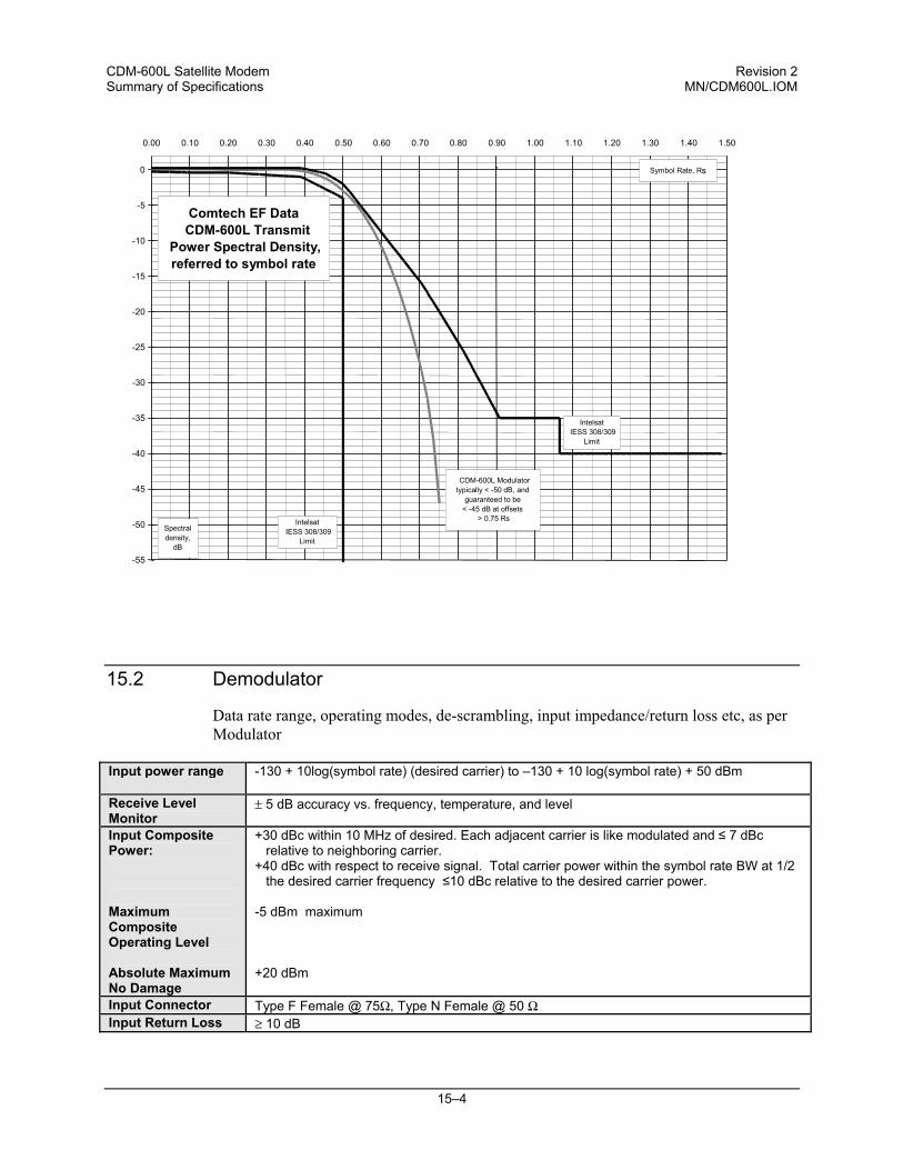
CDM-600L Satellite Modem Revision 2 Summary of Specifications MN/CDM600L.IOM
15–4
15.2 Demodulator
Data rate range, operating modes, de-scrambling, input impedance/return loss etc, as per Modulator
Input power range -130 + 10log(symbol rate) (desired carrier) to –130 + 10 log(symbol rate) + 50 dBm
Receive Level Monitor
± 5 dB accuracy vs. frequency, temperature, and level
Input Composite Power: Maximum Composite Operating Level Absolute Maximum No Damage
+30 dBc within 10 MHz of desired. Each adjacent carrier is like modulated and ≤ 7 dBc relative to neighboring carrier.
+40 dBc with respect to receive signal. Total carrier power within the symbol rate BW at 1/2 the desired carrier frequency ≤10 dBc relative to the desired carrier power.
-5 dBm maximum +20 dBm
Input Connector Type F Female @ 75Ω, Type N Female @ 50 Ω Input Return Loss ≥ 10 dB
-55
-50
-45
-40
-35
-30
-25
-20
-15
-10
-5
0 0.00 0.10 0.20 0.30 0.40 0.50 0.60 0.70 0.80 0.90 1.00 1.10 1.20 1.30 1.40 1.50
CDM-600L Modulatortypically < -50 dB, and
guaranteed to be < -45 dB at offsets
> 0.75 Rs
Comtech EF Data CDM-600L Transmit
Power Spectral Density, referred to symbol rate
Symbol Rate, R s
Spectral density,
dB Intelsat
IESS 308/309 Limit
Intelsat IESS 308/309
Limit
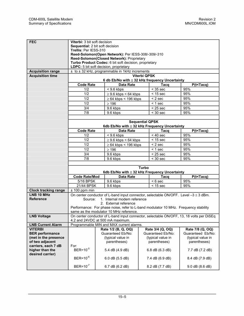
CDM-600L Satellite Modem Revision 2 Summary of Specifications MN/CDM600L.IOM
15–5
FEC Viterbi: 3 bit soft decision
Sequential: 2 bit soft decision Trellis: Per IESS-310 Reed-Solomon(Open Network): Per IESS-308/-309/-310 Reed-Solomon(Closed Network): Proprietary Turbo Product Codec: 6 bit soft decision, proprietary LDPC: 5 bit soft decision, proprietary
Acquisition range ± to ± 32 kHz, programmable in 1kHz increments Acquisition time Viterbi QPSK
6 db Eb/No with ± 32 kHz frequency Uncertainty Code Rate Data Rate Tacq P(t<Tacq) 1/2 < 9.6 kbps < 35 sec 95% 1/2 ≥ 9.6 kbps < 64 kbps < 15 sec 95% 1/2 ≥ 64 kbps < 196 kbps < 2 sec 95% 1/2 ≥ 196 < 1 sec 95% 3/4 9.6 kbps < 25 sec 95% 7/8 9.6 kbps < 30 sec 95% Sequential QPSK
6db Eb/No with ± 32 kHz Frequency Uncertainty Code Rate Data Rate Tacq P(t<Tacq) 1/2 < 9.6 kbps < 40 sec 95% 1/2 ≥ 9.6 kbps < 64 kbps < 15 sec 95% 1/2 ≥ 64 kbps < 196 kbps < 2 sec 95% 1/2 ≥ 196 < 1 sec 95% 3/4 9.6 kbps < 25 sec 95% 7/8 9.6 kbps < 30 sec 95% Turbo
6db Eb/No with ± 32 kHz Frequency Uncertainty Code Rate/Mod Data Rate Tacq P(t<Tacq) 5/16 BPSK 9.6 kbps < 6 sec 95% 21/44 BPSK 9.6 kbps < 15 sec 95% Clock tracking range ± 100 ppm min LNB 10 MHz Reference
On center conductor of L-band input connector, selectable ON/OFF. Level –3 ± 3 dBm. Source: 1. Internal modem reference
2. External reference Performance: For phase noise, refer to L-band modulator 10 MHz. Frequency stability same as the modulator 10 MHz reference.
LNB Voltage On center conductor of L-band input connector, selectable ON/OFF, 13, 18 volts per DiSEq 4.2 and 24VDC at 500 mA maximum.
LNB Current Alarm Programmable MIN and MAX current alarms. VITERBI BER performance (met in the presence of two adjacent carriers, each 7 dB higher than the desired carrier)
For:
BER=10-5
BER=10-6
BER=10-7
Rate 1/2 (B, Q, OQ) Guaranteed Eb/No:
(typical value in parentheses)
5.4 dB (4.9 dB)
6.0 dB (5.5 dB)
6.7 dB (6.2 dB)
Rate 3/4 (Q, OQ) Guaranteed Eb/No:
(typical value in parentheses)
6.8 dB (6.3 dB)
7.4 dB (6.9 dB)
8.2 dB (7.7 dB)
Rate 7/8 (Q, OQ) Guaranteed Eb/No:
(typical value in parentheses)
7.7 dB (7.2 dB)
8.4 dB (7.9 dB)
9.0 dB (8.6 dB)
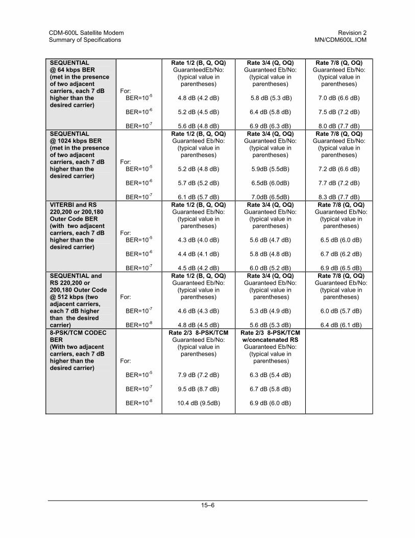
CDM-600L Satellite Modem Revision 2 Summary of Specifications MN/CDM600L.IOM
15–6
SEQUENTIAL @ 64 kbps BER (met in the presence of two adjacent carriers, each 7 dB higher than the desired carrier)
For:
BER=10-5
BER=10-6
BER=10-7
Rate 1/2 (B, Q, OQ) GuaranteedEb/No:
(typical value in parentheses)
4.8 dB (4.2 dB)
5.2 dB (4.5 dB)
5.6 dB (4.8 dB)
Rate 3/4 (Q, OQ) Guaranteed Eb/No:
(typical value in parentheses)
5.8 dB (5.3 dB)
6.4 dB (5.8 dB)
6.9 dB (6.3 dB)
Rate 7/8 (Q, OQ) Guaranteed Eb/No:
(typical value in parentheses)
7.0 dB (6.6 dB)
7.5 dB (7.2 dB)
8.0 dB (7.7 dB)
SEQUENTIAL @ 1024 kbps BER (met in the presence of two adjacent carriers, each 7 dB higher than the desired carrier)
For:
BER=10-5
BER=10-6
BER=10-7
Rate 1/2 (B, Q, OQ) Guaranteed Eb/No:
(typical value in parentheses)
5.2 dB (4.8 dB)
5.7 dB (5.2 dB)
6.1 dB (5.7 dB)
Rate 3/4 (Q, OQ) Guaranteed Eb/No:
(typical value in parentheses)
5.9dB (5.5dB)
6.5dB (6.0dB)
7.0dB (6.5dB)
Rate 7/8 (Q, OQ) Guaranteed Eb/No:
(typical value in parentheses)
7.2 dB (6.6 dB)
7.7 dB (7.2 dB)
8.3 dB (7.7 dB)
VITERBI and RS 220,200 or 200,180 Outer Code BER (with two adjacent carriers, each 7 dB higher than the desired carrier)
For:
BER=10-5
BER=10-6
BER=10-7
Rate 1/2 (B, Q, OQ) Guaranteed Eb/No:
(typical value in parentheses)
4.3 dB (4.0 dB)
4.4 dB (4.1 dB)
4.5 dB (4.2 dB)
Rate 3/4 (Q, OQ) Guaranteed Eb/No:
(typical value in parentheses)
5.6 dB (4.7 dB)
5.8 dB (4.8 dB)
6.0 dB (5.2 dB)
Rate 7/8 (Q, OQ) Guaranteed Eb/No:
(typical value in parentheses)
6.5 dB (6.0 dB)
6.7 dB (6.2 dB)
6.9 dB (6.5 dB)
SEQUENTIAL and RS 220,200 or 200,180 Outer Code @ 512 kbps (two adjacent carriers, each 7 dB higher than the desired carrier)
For:
BER=10-7
BER=10-8
Rate 1/2 (B, Q, OQ) Guaranteed Eb/No:
(typical value in parentheses)
4.6 dB (4.3 dB)
4.8 dB (4.5 dB)
Rate 3/4 (Q, OQ) Guaranteed Eb/No:
(typical value in parentheses)
5.3 dB (4.9 dB)
5.6 dB (5.3 dB)
Rate 7/8 (Q, OQ) Guaranteed Eb/No:
(typical value in parentheses)
6.0 dB (5.7 dB)
6.4 dB (6.1 dB)
8-PSK/TCM CODEC BER (With two adjacent carriers, each 7 dB higher than the desired carrier)
For:
BER=10-5
BER=10-7
BER=10-8
Rate 2/3 8-PSK/TCM Guaranteed Eb/No:
(typical value in parentheses)
7.9 dB (7.2 dB)
9.5 dB (8.7 dB)
10.4 dB (9.5dB)
Rate 2/3 8-PSK/TCM w/concatenated RS Guaranteed Eb/No:
(typical value in parentheses)
6.3 dB (5.4 dB)
6.7 dB (5.8 dB)
6.9 dB (6.0 dB)
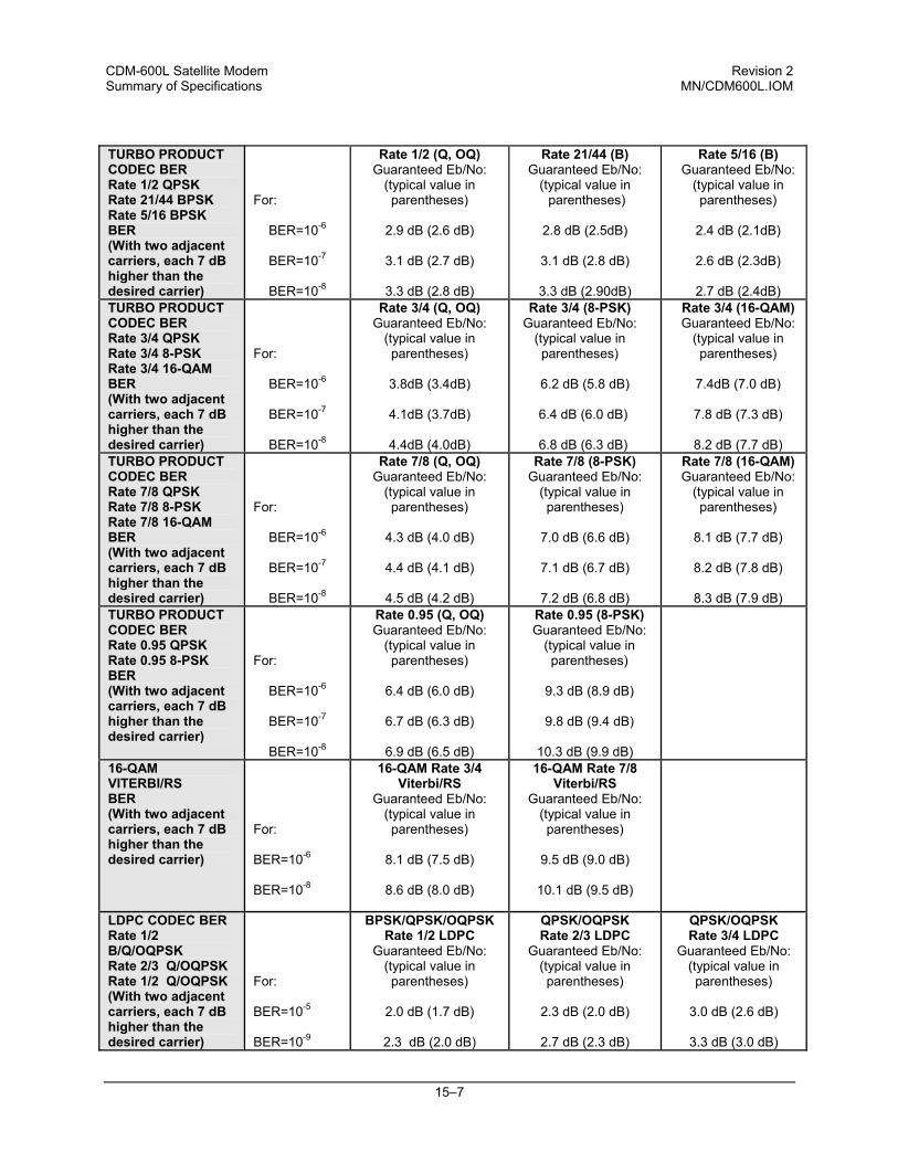
CDM-600L Satellite Modem Revision 2 Summary of Specifications MN/CDM600L.IOM
15–7
TURBO PRODUCT CODEC BER Rate 1/2 QPSK Rate 21/44 BPSK Rate 5/16 BPSK BER (With two adjacent carriers, each 7 dB higher than the desired carrier)
For:
BER=10-6
BER=10-7
BER=10-8
Rate 1/2 (Q, OQ) Guaranteed Eb/No:
(typical value in parentheses)
2.9 dB (2.6 dB)
3.1 dB (2.7 dB)
3.3 dB (2.8 dB)
Rate 21/44 (B) Guaranteed Eb/No:
(typical value in parentheses)
2.8 dB (2.5dB)
3.1 dB (2.8 dB)
3.3 dB (2.90dB)
Rate 5/16 (B) Guaranteed Eb/No:
(typical value in parentheses)
2.4 dB (2.1dB)
2.6 dB (2.3dB)
2.7 dB (2.4dB)
TURBO PRODUCT CODEC BER Rate 3/4 QPSK Rate 3/4 8-PSK Rate 3/4 16-QAM BER (With two adjacent carriers, each 7 dB higher than the desired carrier)
For:
BER=10-6
BER=10-7
BER=10-8
Rate 3/4 (Q, OQ) Guaranteed Eb/No:
(typical value in parentheses)
3.8dB (3.4dB)
4.1dB (3.7dB)
4.4dB (4.0dB)
Rate 3/4 (8-PSK) Guaranteed Eb/No:
(typical value in parentheses)
6.2 dB (5.8 dB)
6.4 dB (6.0 dB)
6.8 dB (6.3 dB)
Rate 3/4 (16-QAM) Guaranteed Eb/No:
(typical value in parentheses)
7.4dB (7.0 dB)
7.8 dB (7.3 dB)
8.2 dB (7.7 dB)
TURBO PRODUCT CODEC BER Rate 7/8 QPSK Rate 7/8 8-PSK Rate 7/8 16-QAM BER (With two adjacent carriers, each 7 dB higher than the desired carrier)
For:
BER=10-6
BER=10-7
BER=10-8
Rate 7/8 (Q, OQ) Guaranteed Eb/No:
(typical value in parentheses)
4.3 dB (4.0 dB)
4.4 dB (4.1 dB)
4.5 dB (4.2 dB)
Rate 7/8 (8-PSK) Guaranteed Eb/No:
(typical value in parentheses)
7.0 dB (6.6 dB)
7.1 dB (6.7 dB)
7.2 dB (6.8 dB)
Rate 7/8 (16-QAM) Guaranteed Eb/No:
(typical value in parentheses)
8.1 dB (7.7 dB)
8.2 dB (7.8 dB)
8.3 dB (7.9 dB)
TURBO PRODUCT CODEC BER Rate 0.95 QPSK Rate 0.95 8-PSK BER (With two adjacent carriers, each 7 dB higher than the desired carrier)
For:
BER=10-6
BER=10-7
BER=10-8
Rate 0.95 (Q, OQ) Guaranteed Eb/No:
(typical value in parentheses)
6.4 dB (6.0 dB)
6.7 dB (6.3 dB)
6.9 dB (6.5 dB)
Rate 0.95 (8-PSK) Guaranteed Eb/No:
(typical value in parentheses)
9.3 dB (8.9 dB)
9.8 dB (9.4 dB)
10.3 dB (9.9 dB)
16-QAM VITERBI/RS BER (With two adjacent carriers, each 7 dB higher than the desired carrier)
For:
BER=10-6
BER=10-8
16-QAM Rate 3/4 Viterbi/RS
Guaranteed Eb/No: (typical value in parentheses)
8.1 dB (7.5 dB)
8.6 dB (8.0 dB)
16-QAM Rate 7/8 Viterbi/RS
Guaranteed Eb/No: (typical value in parentheses)
9.5 dB (9.0 dB)
10.1 dB (9.5 dB)
LDPC CODEC BER Rate 1/2 B/Q/OQPSK Rate 2/3 Q/OQPSK Rate 1/2 Q/OQPSK (With two adjacent carriers, each 7 dB higher than the desired carrier)
For: BER=10-5 BER=10-9
BPSK/QPSK/OQPSK Rate 1/2 LDPC
Guaranteed Eb/No: (typical value in parentheses)
2.0 dB (1.7 dB)
2.3 dB (2.0 dB)
QPSK/OQPSK Rate 2/3 LDPC
Guaranteed Eb/No: (typical value in parentheses)
2.3 dB (2.0 dB)
2.7 dB (2.3 dB)
QPSK/OQPSK Rate 3/4 LDPC
Guaranteed Eb/No: (typical value in parentheses)
3.0 dB (2.6 dB)
3.3 dB (3.0 dB)
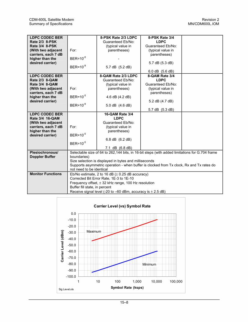
CDM-600L Satellite Modem Revision 2 Summary of Specifications MN/CDM600L.IOM
15–8
LDPC CODEC BER Rate 2/3 8-PSK Rate 3/4 8-PSK (With two adjacent carriers, each 7 dB higher than the desired carrier)
For: BER=10-5 BER=10-9
8-PSK Rate 2/3 LDPC Guaranteed Eb/No:
(typical value in parentheses)
-
5.7 dB (5.2 dB)
8-PSK Rate 3/4 LDPC
Guaranteed Eb/No: (typical value in parentheses)
5.7 dB (5.3 dB)
6.0 dB (5.6 dB)
LDPC CODEC BER Rate 2/3 8-QAM Rate 3/4 8-QAM (With two adjacent carriers, each 7 dB higher than the desired carrier)
For:
BER=10-5 BER=10-9
8-QAM Rate 2/3 LDPC Guaranteed Eb/No:
(typical value in parentheses)
4.6 dB (4.2 dB)
5.0 dB (4.6 dB)
8-QAM Rate 3/4 LDPC
Guaranteed Eb/No: (typical value in parentheses)
5.2 dB (4.7 dB)
5.7 dB (5.3 dB)
LDPC CODEC BER Rate 3/4 16-QAM (With two adjacent carriers, each 7 dB higher than the desired carrier)
For: BER=10-5 BER=10-5
16-QAM Rate 3/4 LDPC
Guaranteed Eb/No: (typical value in parentheses)
6.8 dB (6.2 dB)
7.1 dB (6.8 dB)
Plesiochronous/ Doppler Buffer
Selectable size of 64 to 262,144 bits, in 16-bit steps (with added limitations for G.704 frame boundaries) Size selection is displayed in bytes and milliseconds Supports asymmetric operation - when buffer is clocked from Tx clock, Rx and Tx rates do not need to be identical
Monitor Functions Eb/No estimate, 2 to 16 dB (± 0.25 dB accuracy) Corrected Bit Error Rate, 1E-3 to 1E-10 Frequency offset, ± 32 kHz range, 100 Hz resolution Buffer fill state, in percent Receive signal level (-20 to –60 dBm, accuracy is ± 2.5 dB)
Carrier Level (vs) Symbol Rate
-100.0
-90.0
-80.0
-70.0
-60.0
-50.0
-40.0
-30.0
-20.0
-10.0
0.0
1 10 100 1,000 10,000 100,000
Symbol Rate (ksps)
Car
rier L
evel
(dB
m)
Minimum
Maximum
Sig Level.xls

CDM-600L Satellite Modem Revision 2 Summary of Specifications MN/CDM600L.IOM
15–9
15.3 Automatic Uplink Power Control
Operating Mode Requires Closed Network Framed mode (EDMAC, D&I++, or ESC++) for transport of Eb/No
information from remote modem Target Eb/No range 0 to 9.9 dB at remote demod (default is 4.0 dB) Max AUPC range 0 to 9 dB (default is 3 dB) Monitor functions Remote demod Eb/No
Tx power level increase (front panel or via remote control interface)
15.4 Data Interfaces
Primary Data (3 selectable modes)
RS-422/RS-530 DCE (Rates up to 10 Mbps) (also supports X.21 DCE & DTE and 8k ESC orderwire for IDR) V.35 DCE (Rates up to 10 Mbps) Synchronous RS-232 (Rates up to 300 kbps) LVDS serial (Rates up to 20 Mbps) HSSI - Requires optional CIC-20 Converter (Rates up to 20 Mbps)
25-pin D-sub (female)
G.703 (Tx In, Drop Out, Insert In, Rx Out)
1.544 Mbps T1 (Balanced 100 Ω) 6.312 Mbps T2 (unbalanced 75 Ω or balanced 110 Ω) 2.048 Mbps E1 (unbalanced 75 Ω or balanced 120 Ω) 8.448 Mbps E2 (unbalanced 75 Ω) Note: All Drop and Insert modes are a FAST option.
15-pin D-sub (female) or BNC (female)
External Reference In
2.4 kHz – 10 MHz, in 1 Hz steps (locks baseband clocks only) TTL level (unbalanced) or sine wave @ 0dBm nominal
BNC (female)
Overhead Data RS-422 octet clocks for IDR ESC & IBS RS-422 IDR 64 kbps ESC data & clock RS-232 IBS ESC data & clock RS-422 External Clock input IDR BWA Inputs RS-232 High Rate ESC data ( with IBS FAST) RS-232 ESC++ data ( with Firmware version 1.3.0 or higher)
25-pin D-sub (male)
Modem Alarms Relay outputs (Tx, Rx & unit faults) Demodulator I & Q test outputs (constellation) Demodulator Rx Signal Level output (0 to 2.5 volts) External carrier off input
15-pin D-sub (male)
IDR BWA Outputs 4 backward alarm Form C relay outputs
15-pin D-sub (female)
Remote Control RS-232 or RS-485 modem control and monitoring 9-pin D-sub (male) ADPCM Audio Interface
2 audio channels, each occupying 32 kbps bandwidth as part of IDR overhead or as a 64 kbps primary data rate option. 600 Ω balanced – 0 dBm0 nominal, -6 to +8 dB, 2 dB steps
9-pin D-sub (female)
Auxiliary Serial RS-232 link to other modem in 1:1 pair, via CRS-150 USB Type B Socket
CDM-600L Satellite Modem Revision 2 Summary of Specifications MN/CDM600L.IOM
15–10
15.5 Data Rate Ranges
Code Rate/Modulation FEC Type Data Rate Range Uncoded BPSK None 4.8 kbps to 10.0 Mbps Uncoded QPSK/OQPSK None 9.6 kbps to 20 Mbps Rate 1/2 BPSK Viterbi 2.4 kbps to 5.0 Mbps Rate 1/2 BPSK Sequential 2.4 kbps to 1.024 Mbps Rate 1/2 BPSK Viterbi with R-S 2.4 kbps to 4.444 Mbps Rate 1/2 BPSK Sequential with R-S 2.4 kbps to 1.024 Mbps Rate 1/2 QPSK/OQPSK Viterbi 4.8 kbps to 10.0 Mbps Rate 1/2 QPSK/OQPSK Sequential 4.8 kbps to 2.048 Mbps Rate 1/2 QPSK/OQPSK Viterbi with R-S 4.8 kbps to 8.888 Mbps Rate 1/2 QPSK/OQPSK Sequential with R-S 4.8 kbps to 2.048 Mbps Rate 3/4 QPSK/OQPSK Viterbi 7.2 kbps to 15 Mbps Rate 3/4 QPSK/OQPSK Sequential 7.2 kbps to 2.048 Mbps Rate 3/4 QPSK/OQPSK Viterbi with R-S 7.2 kbps to 13.333 Mbps Rate 3/4 QPSK/OQPSK Sequential with R-S 7.2 kbps to 2.048 Mbps Rate 7/8 QPSK/OQPSK Viterbi 8.4 kbps to 17.5 Mbps Rate 7/8 QPSK/OQPSK Sequential 8.4 kbps to 2.048 Mbps Rate 7/8 QPSK/OQPSK Viterbi with R-S 8.4 kbps to 15.555 Mbps Rate 7/8 QPSK/OQPSK Sequential with R-S 8.4 kbps to 2.048 Mbps Rate 2/3 8-PSK TCM 9.6 kbps to 20.0 Mbps Rate 2/3 8-PSK TCM with R-S 9.6 kbps to 17.777 Mbps Rate 3/4 16-QAM Viterbi with R-S 14.4 kbps to 20.0 Mbps Rate 7/8 16-QAM Viterbi with R-S 16.8 kbps to 20.0 Mbps Rate 21/44 BPSK TPC 4.8 kbps to 3.2 Mbps (to 4.77 Mbps with High Rate Turbo card) Rate 5/16 BPSK TPC 4.8 kbps to 2.048 Mbps(to 3.12 Mbps with High Rate Turbo card) Rate 3/4 QPSK/OQPSK TPC 7.2 kbps to 5.0 Mbps (to 15 Mbps with High Rate Turbo card) Rate 3/4 8-PSK TPC 10.8 kbps to 5.0 Mbps (to 20 Mbps with High Rate Turbo card) Rate 3/4 16-QAM TPC 14.4 kbps to 5.0 Mbps (to 20 Mbps with High Rate Turbo card) Rate 1/2 QPSK/OQPSK TPC 4.8 kbps to 9.54 Mbps (High Rate Turbo card only) Rate 7/8 QPSK/OQPSK TPC 8.4 kbps to 17.5 Mbps (High Rate Turbo card only) Rate 0.95 QPSK/OQPSK TPC 9.1 kbps to 18.888 Mbps (High Rate Turbo card only) Rate 7/8 8-PSK TPC 12.6 kbps to 20 Mbps (High Rate Turbo card only) Rate 0.95 8-PSK TPC 13.6 kbps to 20 Mbps (High Rate Turbo card only) Rate 7/8 16-QAM TPC 16.8 kbps to 20 Mbps (High Rate Turbo card only) Rate 1/2 BPSK LDPC 2.4 kbps to 5.0 Mbps (TPC/LDPC codec only) Rate 1/2 QPSK/OQPSK LDPC 4.8 kbps to 10.0 Mbps (TPC/LDPC codec only) Rate 2/3 QPSK/OQPSK LDPC 6.4 kbps to 13.333 Mbps (TPC/LDPC codec only) Rate 3/4 QPSK/OQPSK LDPC 7.2 kbps to 15.0 Mbps (TPC/LDPC codec only) Rate 2/3 8-PSK/8-QAM LDPC 9.6 kbps to 19.0 Mbps (TPC/LDPC codec only) Rate 3/4 8-PSK/8-QAM LDPC 10.8 kbps to 20.0 Mbps (TPC/LDPC codec only) Rate 3/4 16-QAM LDPC 14.4 kbps to 20.0 Mbps (TPC/LDPC codec only) Important Notes: 1) If EDMAC framing is employed, the upper data rate will be reduced by 5% for data rates up to 2.048 Mbps, and by 1.58% for
data rates above 2.048 Mbps) 2) If ESC++ framing is employed, the upper data rate will be reduced 1.58%.
CDM-600L Satellite Modem Revision 2 Summary of Specifications MN/CDM600L.IOM
15–11
15.6 Framing Summary
Transparent EDMAC IDR IBS D&I D&I++ ESC++ Overhead added
None To 2 Mbps: 1.5% Above 2 Mbps: 1.5% (see Note 2)
Fixed 96 kHz 1/15 of front panel data rate
1/15 of front panel data rate Terrestrial is T1 or E1
1/45 of front panel data rate Terrestrial is T1 or E1
Variable: between 11.76% at 64 kbps to 1.58% above 7 Mbps
Available data rates and format
All rates and formats
All rates and formats
T1, E1, T2 and E2; all formats
64 to 2048 kbps only; all formats
Specific multiples of 64 kbps only
Any multiple of 64 kbps, up to n = 24.
All rates and formats
Overhead components
None Remote control link between modems’ processor plus AUPC
EIA-422 ESC (8 kbps) EIA-422 ESC (64 kbps or 2 audio links) 4 BW alarms
EIA-232 Earth station link at 1/480th of primary data rate One BW alarm
EIA-232 Earth station link at 1/480th of primary data rate One BW alarm
Same as EDMAC, plus EIA-232 Earth station link at 1/576th of primary data rate
EIA-232 Earth station link at variable rate, plus AUPC
Additional Reed-Solomon Overhead
200/180 219/201 for IESS-310 mode
200/180 T1 = 225/205 E1 = 219/201 and IESS-310 mode T2/E2 = 94/178
126/112 219/201 for IESS-310 mode
126/112 219/201 for IESS-310 mode
126/112 126/112
Scrambling (see Note 1 )
Basic ITU V.35 (Intelsat)
Proprietary scrambler
Basic ITU V.35 (Intelsat)
IESS-309 scrambler
IESS-309 scrambler
Basic ITU V.35 (Intelsat)
Proprietary scrambler
Notes: 1. Reed-Solomon is Off. 2. 1.5 % for Rates 5/16 or 21/44 BPSK Turbo, Rate 1/2 QPSK/OQPSK Turbo, and all rates > 2 Mbps
15.7 Miscellaneous
Front panel Tactile keypad, 6 keys (Up/Down, Left/Right, Enter/Clear) Vacuum Fluorescent Display (blue) - 2 lines of 40 characters
Loopbacks Internal IF loopback, RF loopback, digital loopback, and inward/outward loopback Fault relays Hardware fault, RX and TX Traffic Alarms, Open Network Backward Alarms M&C Interface RS-232 and RS-485 (addressable multidrop, 2-wire or 4-wire) M&C Software SatMac or CMCS software for control of local and distant units Dimensions 1U high, 12 inches (305 mm) deep Weight 10 lbs (4.5 kgs) max AC consumption 55 watts (maximum) without BUC power supply
290 watts (maximum) with BUC power supply Operating voltage 100 - 240 volts AC, +6%/-10% - autosensing
(total absolute max. range is 90 - 254 volts AC) Optional 38-60 volts DC
Operating temperature 0 to 50oC (32 to 122oF)
CDM-600L Satellite Modem Revision 2 Summary of Specifications MN/CDM600L.IOM
15–12
15.8 Approvals “CE” as follows:
EN 55022 Class B (Emissions) EN 50082-1 (Immunity) EN 60950 (Safety)
EN 61000-3-2 EN 61000-3-3 EN 61000-4-2 EN 61000-4-4 EN 61000-4-5
EN 61000-4-6 EN 61000-4-8 EN 61000-4-9 EN 61000-4-11 EN 61000-4-13
FCC
FCC Part 15 Class B
16–1
Chapter 16. REMOTE CONTROL
16.1 Introduction
This section describes the protocol and message command set for remote monitor and control of the CDM-600L Modem. The electrical interface is either an RS-485 multi-drop bus (for the control of many devices) or an RS-232 connection (for the control of a single device), and data is transmitted in asynchronous serial form, using ASCII characters. Control and status information is transmitted in packets, of variable length, in accordance with the structure and protocol defined in later sections.
16.2 RS-485
For applications where multiple devices are to be monitored and controlled, a full-duplex (or 4-wire) RS-485 is preferred. Half-duplex (2-wire) RS-485 is possible, but is not preferred. In full-duplex RS-485 communication there are two separate, isolated, independent, differential-mode twisted pairs, each handling serial data in different directions. It is assumed that there is a ‘controller’ device (a PC or dumb terminal), which transmits data, in a broadcast mode, via one of the pairs. Many ‘target’ devices are connected to this pair, which all simultaneously receive data from the controller. The controller is the only device with a line-driver connected to this pair - the target devices only have line-receivers connected. In the other direction, on the other pair, each target has a tri-stateable line driver connected, and the controller has a line-receiver connected. All the line drivers are held in high-impedance mode until one (and only one) target transmits back to the controller.
CDM-600L Satellite Modem Revision 2 Remote Control MN/CDM600L.IOM
16–2
Each target has a unique address, and each time the controller transmits, in a framed ‘packet’ of data, the address of the intended recipient target is included. All of the targets receive the packet, but only one (the intended) will reply. The target enables its output line driver, and transmits its return data packet back to the controller, in the other direction, on the physically separate pair. RS 485 (full duplex) summary:
• Two differential pairs - one pair for controller to target, one pair for target to controller.
• Controller-to-target pair has one line driver (controller), and all targets have line-receivers.
• Target-to-controller pair has one line receiver (controller), and all targets have tri-state drivers.
16.3 RS-232
This a much simpler configuration in which the controller device is connected directly to the target via a two-wire-plus-ground connection. Controller-to-target data is carried, via RS-232 electrical levels, on one conductor, and target-to-controller data is carried in the other direction on the other conductor.
16.4 Basic Protocol
Whether in RS-232 or RS-485 mode, all data is transmitted as asynchronous serial characters, suitable for transmission and reception by a UART. In this case, the asynchronous character formats include 7O2, 7E2, and 8N1. The baud rate may vary between 1200 and 38,400 baud. All data is transmitted in framed packets. The controller is assumed to be a PC or ASCII dumb terminal, which is in charge of the process of monitor and control. The controller is the only device which is permitted to initiate, at will, the transmission of data. Targets are only permitted to transmit when they have been specifically instructed to do so by the controller. All bytes within a packet are printable ASCII characters, less than ASCII code 127. In this context, the Carriage Return and Line Feed characters are considered printable. All messages from controller to target require a response (with one exception). This will be either to return data which has been requested by the controller, or to acknowledge reception of an instruction to change the configuration of the target. The exception to this is when the controller broadcasts a message (such as Set time/date) using Address 0, when the target is set to RS-485 mode.
CDM-600L Satellite Modem Revision 2 Remote Control MN/CDM600L.IOM
16–3
16.5 Packet Structure
Controller-to-target:
Start of Packet Target Address Address De-limiter
Instruction Code
Code Qualifier
Optional Arguments
End of Packet
< ASCII code 60
(1 character)
(4 characters)
/ ASCII code 47
(1 character)
(3 characters)
= or ? ASCII code 61
or 63 (1 character)
(n characters)
Carriage Return ASCII code 13
(1 character)
Example: <0135/TFT=1 [CR] Target-to-controller:
Start of Packet Target Address
Address De-limiter
Instruction Code
Code Qualifier Optional Arguments
End of Packet
> ASCII
code 62 (1 character)
(4 characters)
/ ASCII
code 47 (1 character)
(3 characters)
=, ?, !, or * ASCII code 61,
63, 33 or 42 (1 character)
(From 0 to n characters)
Carriage Return, Line Feed
ASCII code 13,10 (2 characters)
Example: >0654/RSW=32 [CR][LF] Each of the components of the packet is now explained.
16.5.1 Start Of Packet
Controller to Target: This is the character ‘<’ (ASCII code 60) Target to Controller: This is the character ‘>’ (ASCII code 62) Because this is used to provide a reliable indication of the start of packet, these two characters may not appear anywhere else within the body of the message.
16.5.2 Address
Up to 9999 devices can be uniquely addressed. In RS-232 applications this value is set to 0. In RS-485 applications, the permissible range of values is 1 to 9999. It is programmed into a target unit using the front panel keypad.
IMPORTANT
The controller sends a packet with the address of a target - the destination of the packet. When the target responds, the address used is the same address, to indicate to the controller the source of the packet. The controller does not have its own address.
CDM-600L Satellite Modem Revision 2 Remote Control MN/CDM600L.IOM
16–4
16.5.3 Instruction Code
This is a three-character alphabetic sequence which identifies the subject of the message. Wherever possible, the instruction codes have been chosen to have some significance. For example: TFQ for transmit frequency, RMD for receive modulation type, etc. This aids in the readability of the message, should it be displayed in its raw ASCII form. Only upper case alphabetic characters may be used (A-Z, ASCII codes 65 - 90).
16.5.4 Instruction Code Qualifier
This is a single character which further qualifies the preceding instruction code. Code Qualifiers obey the following rules: 1) From Controller to Target, the only permitted values are:
= (ASCII code 61) ? (ASCII code 63)
They have these meanings: The ‘=’ code (controller to target) is used as the assignment operator, and is used to indicate that the parameter defined by the preceding byte should be set to the value of the argument(s) which follow it. For example, in a message from controller to target, TFQ=0950.0000 would mean ‘set the transmit frequency to 950 MHz’ The ‘?’ code (controller to target) is used as the query operator, and is used to indicate that the target should return the current value of the parameter defined by the preceding byte. For example, in a message from controller to target, TFQ? would mean ‘return the current value of the transmit frequency’ 2) From Target to Controller, the only permitted values are:
= (ASCII code 61) ? (ASCII code 63) ! (ASCII code 33) * (ASCII code 42) # (ASCII code 35) ~ (ASCII Code 126)
They have these meanings: The ‘=’ code (target to controller) is used in two ways: First, if the controller has sent a query code to a target (for example TFQ?, meaning ‘what’s the Transmit frequency?’), the target would respond with TFQ=xxxx.xxxx, where xxxx.xxxx represents the frequency in question.
CDM-600L Satellite Modem Revision 2 Remote Control MN/CDM600L.IOM
16–5
Second, if the controller sends an instruction to set a parameter to a particular value, then, providing the value sent in the argument is valid, the target will acknowledge the message by replying with TFQ= (with no message arguments). The ? code (target to controller) is only used as follows: If the controller sends an instruction to set a parameter to a particular value, then, if the value sent in the argument is not valid, the target will acknowledge the message by replying (for example) with TFQ? (with no message arguments). This indicates that there was an error in the message sent by the controller. The * code (target to controller) is only used as follows: If the controller sends an instruction to set a parameter to a particular value, then, if the value sent in the argument is valid, BUT the modem will not permit that particular parameter to be changed at that time, the target will acknowledge the message by replying (for example) with TFQ* (with no message arguments). The ! code (target to controller) is only used as follows: If the controller sends an instruction code which the target does not recognize, the target will acknowledge the message by echoing the invalid instruction, followed by the ! character with. Example: XYZ! The # code (target to controller) is only used as follows: If the controller sends a correctly formatted command, BUT the modem is not in remote mode, it will not allow reconfiguration, and will respond with TFQ#. The ~ code (target to controller) is only used as follows: If a message was sent via a local modem to a distant end device or ODU, the message was transmitted transparently through the local modem. In the event of the distant-end device not responding, the local modem would generate a response e.g. 0001/RET~, indicating that it had finished waiting for a response and was now ready for further comms.
16.5.5 Message Arguments
Arguments are not required for all messages. Arguments may include the ASCII characters: 0 to 9 (ASCII 48 to 57), A to Z (ASCII-65-90), space (ASCII 32), * (ASCII 42), + (ASCII 43), - (ASCII 45), / (ASCII 47), period (ASCII 46) and comma (ASCII 44).
16.5.6 End Of Packet
Controller to Target: This is the ‘Carriage Return’ character (ASCII code 13) Target to Controller: This is the two-character sequence ‘Carriage Return’, ‘Line Feed’. (ASCII code 13, and code 10.) Both indicate the valid termination of a packet
CDM-600L Satellite Modem Revision 2 Remote Control MN/CDM600L.IOM
16–6
16.6 Remote Commands
The following remote commands are arranged in the following order:
• Transmit (TX) Commands • Receive (RX) Commands • Unit Commands • Query Commands • Bulk Commands • BUC Commands • LNB Commands
TX Priority System = TIT (Highest priority) , TFM, TFT, TMD, TCR, and TDR (Lowest Priority), indicated by shading. Any change to a higher priority parameter can override any of the parameters of lower priority. RX Priority System = RIT (Highest priority) , RFM, RFT, RMD, RCR, and RDR (Lowest Priority), indicated by shading. Any change to a higher priority parameter can override any of the parameters of lower priority. Exception: Select DROP or INSERT mode using TFM or RFM (Framing type) which is highest priority . Note: The following codes are used in the ‘Response to Command’ column:
= Message ok ? Received ok, but invalid arguments found * Message ok, but not permitted in current mode # Message ok, but unit is not in Remote mode ~ Time out of an EDMAC pass-through message
CDM-600L Satellite Modem Revision 2 Remote Control MN/CDM600L.IOM
16–7
16.6.1 TX Remote Commands
Parameter Type
Command (Instruction
Code and Qualifier)
Arguments for Command or Response
to Query
Description of Arguments Response to Command
Query (Instruction
Code and Qualifier)
Response to Query
Tx Frequency TFQ= 9 bytes Command or Query. Tx Frequency, 950 to 1950 MHz, Resolution=100Hz. Example: TFQ=0950.9872
TFQ= TFQ? TFQ* TFQ#
TFQ? TFQ=xxxx.xxxx (see description of arguments)
Tx Interface Type
TIT= 1 byte, value 0 thru 6
Command or Query. Tx Interface Type, where: 0=RS422 1=V.35 2=RS232 (synchronous) 3=Balanced G.703 4=Unbalanced G.703 5=Audio (Data rate fixed at 64 kbps) (IBS/EDMAC only) 6=LVDS Example: TIT=1 (selects V.35)
TIT= TIT? TIT* TIT#
TIT? TIT=x (see description of arguments)
Tx Framing Mode
TFM= 1 byte, value of 0 thru 6
Command or Query. Tx Framing mode, where: 0=Unframed 1=IBS 2=IDR 3=DROP (Requires D&I FAST option) 4=EDMAC 5=D&I++ (Requires D&I FAST option) (Ver 1.2.0 or greater) 6=ESC++ (Requires Ver 1.3.0 or greater) If TFM=4 is selected, Rx framing is driven to EDMAC to match. Example: TFM=0 (selects Unframed mode)
TFM= TFM? TFM* TFM#
TFM? TFM=x (see description of arguments)
CDM-600L Satellite Modem Revision 2 Remote Control MN/CDM600L.IOM
16–8
Parameter Type
Command (Instruction
Code and Qualifier)
Arguments for Command or Response
to Query
Description of Arguments Response to Command
Query (Instruction
Code and Qualifier)
Response to Query
Tx FEC Type TFT= 1 byte, value of 0 thru 9
Command or Query. Tx FEC coding type, where: 0=None (uncoded, rate 1/1) with differential encoding ON 1=Viterbi 2=Viterbi + Reed-Solomon 3=Sequential 4=Sequential + Reed-Solomon 5=TCM (Trellis Code Modulation) (Forces TCR=3 2/3) 6=TCM + Reed-Solomon (Forces TCR=3 2/3) 7=Turbo (TPC) 8=None (uncoded, rate 1/1) with differential encoding OFF 9=LDPC (Requires TPC/LDPC codec) Example: TFT=1 (which is Viterbi coding)
TFT= TFT? TFT* TFT#
TFT? TFT=x (see description of arguments)
Tx Modulation Type
TMD= 1 byte, value of 0 thru 5
Command or Query. Tx Modulation type, where: 0=BPSK 1=QPSK 2=OQPSK 3=8PSK 4=16QAM (Turbo or Viterbi+RS only) 5=8-QAM (LDPC only)(Requires TPC/LDPC codec and
FAST option Depending on FEC type, not all of these selections will be valid. Example: TMD=2 (which is OQPSK)
TMD= TMD? TMD* TMD#
TMD? TMD=x (see description of arguments)
CDM-600L Satellite Modem Revision 2 Remote Control MN/CDM600L.IOM
16–9
Parameter Type
Command (Instruction
Code and Qualifier)
Arguments for Command or Response
to Query
Description of Arguments Response to Command
Query (Instruction
Code and Qualifier)
Response to Query
Tx FEC Code Rate
TCR= 1 byte, value of 0 thru 7
Command or Query Tx Modulation Type, where: 0 = Rate 1/2 1 = Rate 3/4 2 = Rate 7/8 3 = Rate 2/3 (8-PSK TCM or LDPC only) 4 = Rate 1/1 (Uncoded or No FEC) 5 = Rate 21/44 (Turbo Only) 6 = Rate 5/16 (Turbo Only) 7 = Rate 0.95 (Turbo Only) Depending on FEC type, not all of these selections will be valid. Example: TCR=1 (which is Rate 3/4)
TCR= TCR? TCR* TCR#
TCR? TCR=x (see description of arguments)
Tx Data Rate TDR= 9 bytes Command or Query. Tx Data rate, in kbps, between 4.8 kbps and 20 Mbps Resolution=1 bps. Example: TDR=02047.999 (which is 2047.999 kbps) For Hardware Version 2.0 or higher, additional auxiliary G.703 sub-rates are available. These are selected using: 00512.AUX 01024.AUX 02048.AUX The connectors used for the Aux rates are IDI/DDO. The Aux rates are not available with Drop & Insert or IDR.
TDR= TDR? TDR* TDR#
TDR? TDR=xxxxx.xxx (see description of arguments)
Tx Reed-Solomon Encoding
TRS= 1 byte, value of 0 to 3
Command or Query. Tx RS encoding 0=Normal (based on the Open Network framing mode selected) 1=IESS-310 mode Available all framing modes, except EDMAC. 2=EF Data legacy standard (225,205) – unframed only 3=IBS (126,112) – unframed only Example: TRS=0 (This is a ‘don’t care’ if no RS is selected under FEC Type) Available all framing modes, except EDMAC.
TRS= TRS? TRS* TRS#
TRS? TRS=x (see description of arguments)
CDM-600L Satellite Modem Revision 2 Remote Control MN/CDM600L.IOM
16–10
Parameter Type
Command (Instruction
Code and Qualifier)
Arguments for Command or Response
to Query
Description of Arguments Response to Command
Query (Instruction
Code and Qualifier)
Response to Query
Tx Spectrum Invert
TSI= 1 byte, value of 0 or 1
Command or Query. Tx Spectrum Invert selection, where: 0=Normal, 1=Tx Spectrum Inverted Example: TSI=0 (which is normal)
TSI= TSI? TSI* TSI#
TSI? TSI=x (see description of arguments)
Tx Scrambler TSC= 1 byte, value of 0 or 1
Command or Query. Tx Scrambler state, where: 0=Off 1=On 2=IESS-315 when in Turbo mode 2=Special when uncoded or Viterbi ( needs FAST Special option
1 installed) Example: TSC=1 (Scrambler On)
TSC= TSC? TSC* TSC#
TSC? TSC=x (see description of arguments)
Tx Carrier State
TXO= 1 byte, value of 0 thru 4
Command or Query. Tx Carrier State, where: 0=OFF due to front panel or remote control command 1=ON 2=RTI (receive/transmit inhibit) 3=OFF due to ext H/W Tx Carrier Off command (not a valid argument when used as a command) 4=Off due to BUC warm up delay (not a valid argument in a command format.) Note: the front panel Tx LED will flash during this warm-up period. Example: TXO=1 (Tx Carrier ON)
TXO= TXO? TXO* TXO#
TXO? TXO=x (see description of arguments)
Tx Power Level
TPL= 4 bytes Command or Query. Tx Output power level between 0 and -45 dBm (minus sign assumed). Note: Beyond –40 dBm is beyond the specification. Example: TPL=13.4 (Command not valid in AUPC mode) Note: When Output Power Leveling is enabled: Power level
configuration is not allowed. Response will be TPL*. The response to the query TPL? will be the adjusted leveled value.
TPL= TPL? TPL* TPL#
TPL?
TPL=xx.x (see description of arguments)
CDM-600L Satellite Modem Revision 2 Remote Control MN/CDM600L.IOM
16–11
Parameter Type
Command (Instruction
Code and Qualifier)
Arguments for Command or Response
to Query
Description of Arguments Response to Command
Query (Instruction
Code and Qualifier)
Response to Query
Tx Clock Source
TCK= 1 byte, value 0 thru 3
Command or Query. Tx Clock Source, where: 0=Internal 1=Tx Terrestrial 2=Rx Loop-Timed 3=External Clock Example: TCK=0 (selects Internal)
TCK= TCK? TCK* TCK#
TCK? TCK=x (see description of arguments)
Invert Tx Data
ITD= 1 byte, value 0 or 1
Command or Query. Invert Transmit Data 0=Normal 1=Inverted Example: ITD = 1 (selects Inverted TX Data)
ITD= ITD? ITD* ITD#
ITD? ITD=x (see description of arguments)
Tx Ternary Code
TTC=
1 byte, value of 0 thru 3
Command or Query. (G.703 Parameter) Tx Ternary Code, where: 0=AMI 1=B8ZS 2=B6ZS 3=HDB3 Example: TTC=1 (selects B8ZS)
TTC= TTC? TTC* TTC#
TTC?
TTC=x (see description of arguments)
Tx Audio Volume Control
TVL= 4 bytes Command or Query. (Audio/IDR Parameter) Tx Audio Volume control, in the form aabb, where: aa=Tx 1 volume control in dB, values defined below. bb=Tx 2 volume control in dB, values defined below. Valid values: -6, -4, -2, +0, +2, +4, +6, +8 Example: TVL= -2+4 (sets Tx 1 to 2 dB and Tx 2 to +4 dB)
TVL= TVL? TVL* TVL#
TVL?
TVL=aabb (see description of arguments)
Transmit Backward Alarms Enable
TBA= 4 bytes, each a value of 0 thru 2
Command or Query. (IDR Parameter) Transmit Backward Alarm enable: 0=Disable 1=Enable Internal (S/W) 2=Enable External (H/W) Position indicates backward alarm numbers: 1234 Example: TBA=0120
TBA= TBA? TBA* TBA#
TBA? TBA=xxxx (see description of arguments)
CDM-600L Satellite Modem Revision 2 Remote Control MN/CDM600L.IOM
16–12
Parameter Type
Command (Instruction
Code and Qualifier)
Arguments for Command or Response
to Query
Description of Arguments Response to Command
Query (Instruction
Code and Qualifier)
Response to Query
Transmit ESC Type
TET= 1 byte, value of 0 or 1
Command or Query. (IDR Parameter) Sets or queries IDR Transmit ESC Type, where: 0=64k data channel 1=2 Audio channels
TET= TET? TET* TET#
TET? TET=x (see description of arguments)
Drop Type DTY= 1 byte, value of 0 thru 3
Command or Query. (Drop/D&I++ parameter) Drop Type, where: 0=T1 – D4 1=T1 – ESF 2=E1 – CCS 3=E1 – CAS
DTY= DTY? DTY* DTY#
DTY? DTY=x (see description of arguments)
Drop Timeslot DTS= 3 bytes Command or query. (Drop parameter) (Note: Command and query have different formats) Command format: DTS=xxy Where xx = Channel 01 through 24 y = timeslot, 0-9, A(10) thru V(31).
DTS= DTS? DTS* DTS#
DTS? DTS=yyyyyyyyyyyyyyyyyyyyyyyy indicating all 24 Drop timeslot values associated with the 24 Tx Satellite channels.
Transmit Terrestrial Alarm Mask
TTA= 1 byte, value of 0 or 1
Command or Query. (Drop parameter) Transmit Terrestrial Alarm mask conditions where: 0=Alarm Active 1=Alarm Masked Example: TTA=0, Alarm Active
TTA= TTA? TTA* TTA#
TTA? TTA=x (see description of arguments)
TX LO Frequency
TLO= 6 bytes Command or Query. BUC transmit LO frequency information in the form: xxxxxs, where: xxxxx is the LO frequency, in the range of 3000 to 65000 MHz or 0 (OFF) s is the sign for the MIX Note: For additional information refer to Chapter 17. LO, MIX , and Spectrum Settings. Terminal Frequency = BUC LO ± TFQ
TLO= TLO? TLO* TLO#
TLO? TLO=xxxxxs (see description of arguments)
CDM-600L Satellite Modem Revision 2 Remote Control MN/CDM600L.IOM
16–13
16.6.2 RX Remote Commands
Parameter Type
Command (Instruction
Code and Qualifier)
Arguments for Command or Response
to Query
Description of Arguments Response to Command
Query (Instruction
Code and Qualifier)
Response to Query
Rx Frequency RFQ= 9 bytes Command or Query. Rx Frequency, 950 to 1950 MHz Resolution=100 Hz Example: RFQ=0950.9872
RFQ= RFQ? RFQ* RFQ#
RFQ? RFQ=xxxx.xxxx (see description of arguments)
Rx Interface Type
RIT= 1 byte, value of 0 thru 6
Command or Query. Rx Interface Type, where: 0=RS422 1=V.35 2=RS232 (synchronous) 3=Balanced G.703 4=Unbalanced G.703 5=Audio (Data rate is fixed at 64 kbps) (IBS/EDMAC only) 6=LVDS Example: RIT=1 (selects V.35)
RIT= RIT? RIT* RIT#
RIT? RIT=x (see description of arguments)
Rx Framing Mode
RFM= 1 byte, value of 0 thru 6
Command or Query. Rx Framing mode, where: 0=Unframed 1=IBS 2=IDR 3=INSERT (requires D&I FAST option) 4=EDMAC 5=D&I++ (requires D&I FAST option) (version 1.2.0 or higher) 6=ESC++ (requires version 1.3.0 or higher) Example: RFM=0 (selects Unframed mode)
RFM= RFM? RFM* RFM#
RFM? RFM=x (see description of arguments)
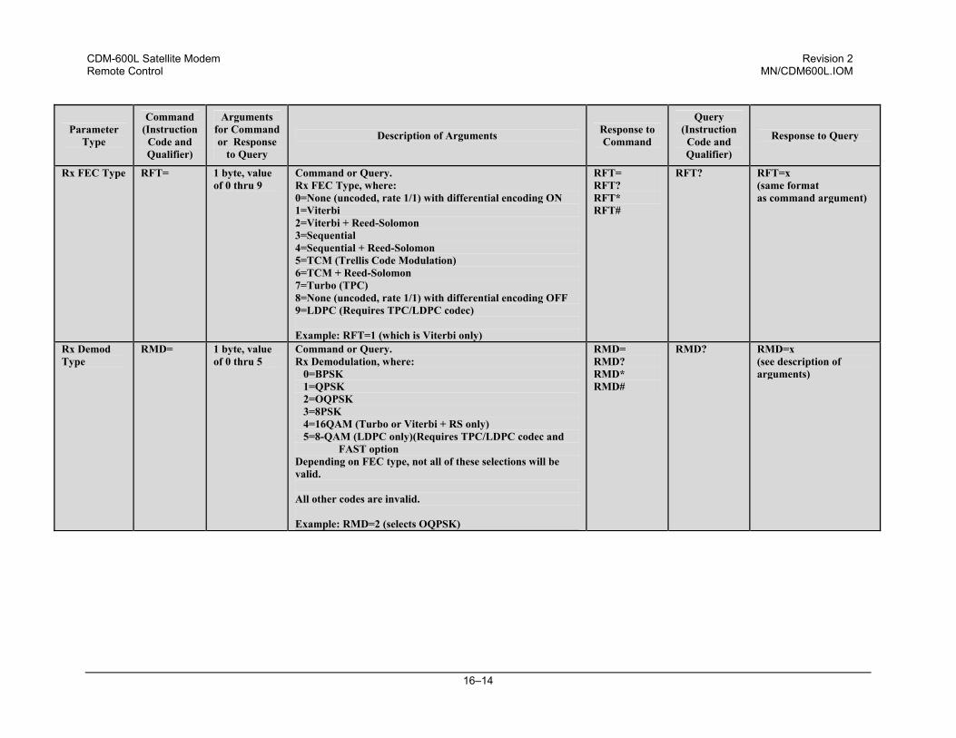
CDM-600L Satellite Modem Revision 2 Remote Control MN/CDM600L.IOM
16–14
Parameter Type
Command (Instruction
Code and Qualifier)
Arguments for Command or Response
to Query
Description of Arguments Response to Command
Query (Instruction
Code and Qualifier)
Response to Query
Rx FEC Type RFT= 1 byte, value of 0 thru 9
Command or Query. Rx FEC Type, where: 0=None (uncoded, rate 1/1) with differential encoding ON 1=Viterbi 2=Viterbi + Reed-Solomon 3=Sequential 4=Sequential + Reed-Solomon 5=TCM (Trellis Code Modulation) 6=TCM + Reed-Solomon 7=Turbo (TPC) 8=None (uncoded, rate 1/1) with differential encoding OFF 9=LDPC (Requires TPC/LDPC codec) Example: RFT=1 (which is Viterbi only)
RFT= RFT? RFT* RFT#
RFT? RFT=x (same format as command argument)
Rx Demod Type
RMD= 1 byte, value of 0 thru 5
Command or Query. Rx Demodulation, where: 0=BPSK 1=QPSK 2=OQPSK 3=8PSK 4=16QAM (Turbo or Viterbi + RS only) 5=8-QAM (LDPC only)(Requires TPC/LDPC codec and
FAST option Depending on FEC type, not all of these selections will be valid. All other codes are invalid. Example: RMD=2 (selects OQPSK)
RMD= RMD? RMD* RMD#
RMD? RMD=x (see description of arguments)
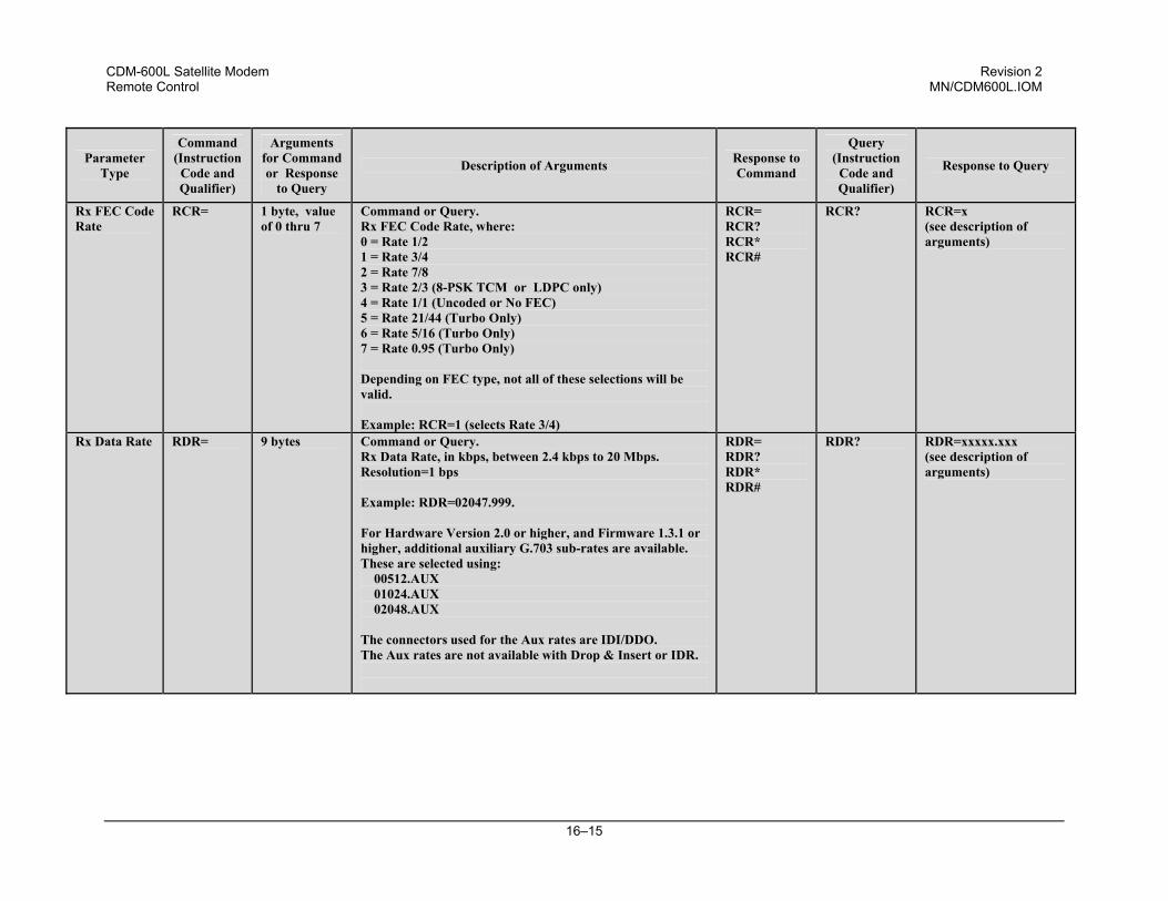
CDM-600L Satellite Modem Revision 2 Remote Control MN/CDM600L.IOM
16–15
Parameter Type
Command (Instruction
Code and Qualifier)
Arguments for Command or Response
to Query
Description of Arguments Response to Command
Query (Instruction
Code and Qualifier)
Response to Query
Rx FEC Code Rate
RCR= 1 byte, value of 0 thru 7
Command or Query. Rx FEC Code Rate, where: 0 = Rate 1/2 1 = Rate 3/4 2 = Rate 7/8 3 = Rate 2/3 (8-PSK TCM or LDPC only) 4 = Rate 1/1 (Uncoded or No FEC) 5 = Rate 21/44 (Turbo Only) 6 = Rate 5/16 (Turbo Only) 7 = Rate 0.95 (Turbo Only) Depending on FEC type, not all of these selections will be valid. Example: RCR=1 (selects Rate 3/4)
RCR= RCR? RCR* RCR#
RCR? RCR=x (see description of arguments)
Rx Data Rate RDR= 9 bytes Command or Query. Rx Data Rate, in kbps, between 2.4 kbps to 20 Mbps. Resolution=1 bps Example: RDR=02047.999. For Hardware Version 2.0 or higher, and Firmware 1.3.1 or higher, additional auxiliary G.703 sub-rates are available. These are selected using: 00512.AUX 01024.AUX 02048.AUX The connectors used for the Aux rates are IDI/DDO. The Aux rates are not available with Drop & Insert or IDR.
RDR= RDR? RDR* RDR#
RDR? RDR=xxxxx.xxx (see description of arguments)
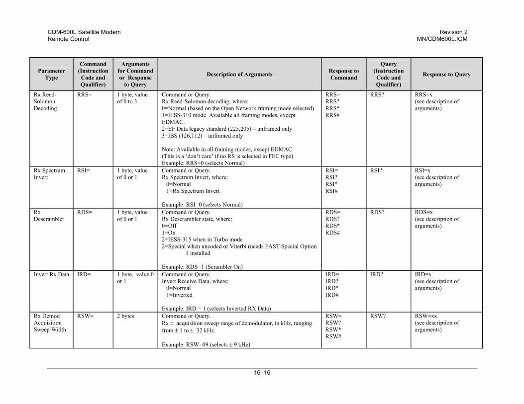
CDM-600L Satellite Modem Revision 2 Remote Control MN/CDM600L.IOM
16–16
Parameter Type
Command (Instruction
Code and Qualifier)
Arguments for Command or Response
to Query
Description of Arguments Response to Command
Query (Instruction
Code and Qualifier)
Response to Query
Rx Reed-Solomon Decoding
RRS= 1 byte, value of 0 to 3
Command or Query. Rx Reed-Solomon decoding, where: 0=Normal (based on the Open Network framing mode selected) 1=IESS-310 mode Available all framing modes, except EDMAC. 2=EF Data legacy standard (225,205) – unframed only 3=IBS (126,112) – unframed only Note: Available in all framing modes, except EDMAC. (This is a ‘don’t care’ if no RS is selected in FEC type) Example: RRS=0 (selects Normal)
RRS= RRS? RRS* RRS#
RRS? RRS=x (see description of arguments)
Rx Spectrum Invert
RSI= 1 byte, value of 0 or 1
Command or Query. Rx Spectrum Invert, where: 0=Normal 1=Rx Spectrum Invert Example: RSI=0 (selects Normal)
RSI= RSI? RSI* RSI#
RSI? RSI=x (see description of arguments)
Rx Descrambler
RDS= 1 byte, value of 0 or 1
Command or Query. Rx Descrambler state, where: 0=Off 1=On 2=IESS-315 when in Turbo mode 2=Special when uncoded or Viterbi (needs FAST Special Option
1 installed Example: RDS=1 (Scrambler On)
RDS= RDS? RDS* RDS#
RDS? RDS=x (see description of arguments)
Invert Rx Data IRD= 1 byte, value 0 or 1
Command or Query. Invert Receive Data, where: 0=Normal 1=Inverted Example: IRD = 1 (selects Inverted RX Data)
IRD= IRD? IRD* IRD#
IRD? IRD=x (see description of arguments)
Rx Demod Acquisition Sweep Width
RSW= 2 bytes Command or Query. Rx ± acquisition sweep range of demodulator, in kHz, ranging from ± 1 to ± 32 kHz. Example: RSW=09 (selects ± 9 kHz)
RSW= RSW? RSW* RSW#
RSW? RSW=xx (see description of arguments)
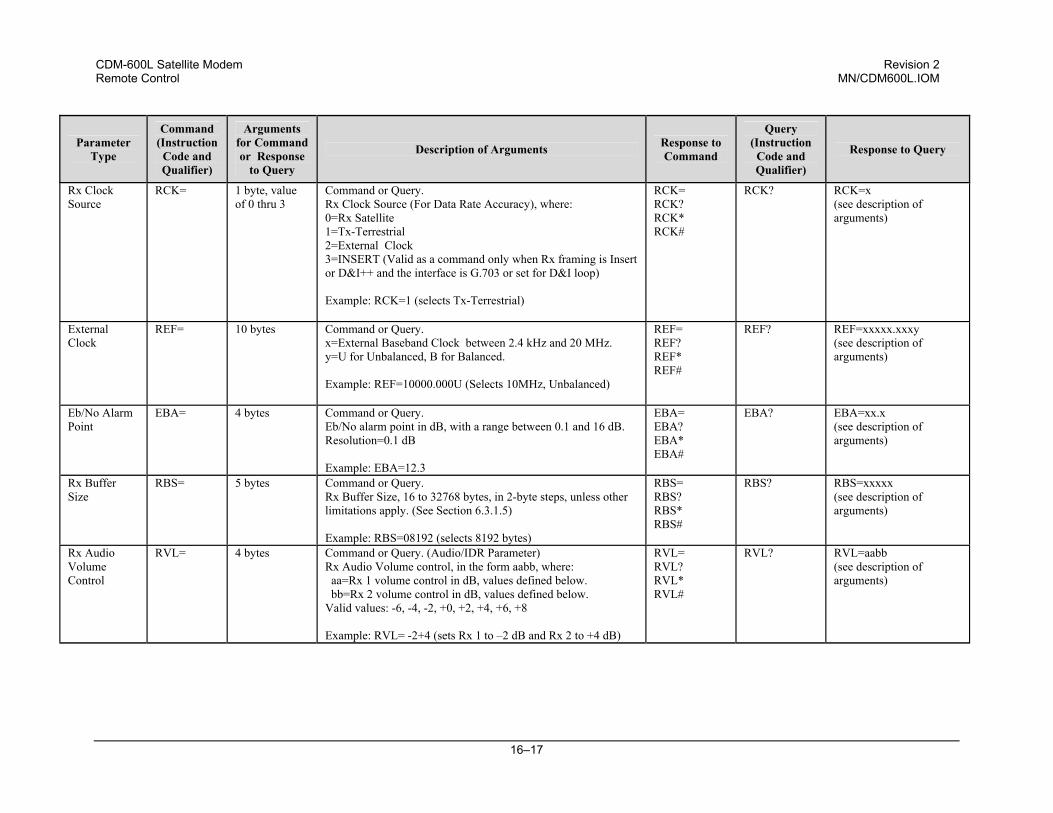
CDM-600L Satellite Modem Revision 2 Remote Control MN/CDM600L.IOM
16–17
Parameter Type
Command (Instruction
Code and Qualifier)
Arguments for Command or Response
to Query
Description of Arguments Response to Command
Query (Instruction
Code and Qualifier)
Response to Query
Rx Clock Source
RCK= 1 byte, value of 0 thru 3
Command or Query. Rx Clock Source (For Data Rate Accuracy), where: 0=Rx Satellite 1=Tx-Terrestrial 2=External Clock 3=INSERT (Valid as a command only when Rx framing is Insert or D&I++ and the interface is G.703 or set for D&I loop) Example: RCK=1 (selects Tx-Terrestrial)
RCK= RCK? RCK* RCK#
RCK? RCK=x (see description of arguments)
External Clock
REF= 10 bytes Command or Query. x=External Baseband Clock between 2.4 kHz and 20 MHz. y=U for Unbalanced, B for Balanced. Example: REF=10000.000U (Selects 10MHz, Unbalanced)
REF= REF? REF* REF#
REF? REF=xxxxx.xxxy (see description of arguments)
Eb/No Alarm Point
EBA= 4 bytes Command or Query. Eb/No alarm point in dB, with a range between 0.1 and 16 dB. Resolution=0.1 dB Example: EBA=12.3
EBA= EBA? EBA* EBA#
EBA? EBA=xx.x (see description of arguments)
Rx Buffer Size
RBS= 5 bytes Command or Query. Rx Buffer Size, 16 to 32768 bytes, in 2-byte steps, unless other limitations apply. (See Section 6.3.1.5) Example: RBS=08192 (selects 8192 bytes)
RBS= RBS? RBS* RBS#
RBS? RBS=xxxxx (see description of arguments)
Rx Audio Volume Control
RVL= 4 bytes Command or Query. (Audio/IDR Parameter) Rx Audio Volume control, in the form aabb, where: aa=Rx 1 volume control in dB, values defined below. bb=Rx 2 volume control in dB, values defined below. Valid values: -6, -4, -2, +0, +2, +4, +6, +8 Example: RVL= -2+4 (sets Rx 1 to –2 dB and Rx 2 to +4 dB)
RVL= RVL? RVL* RVL#
RVL? RVL=aabb (see description of arguments)
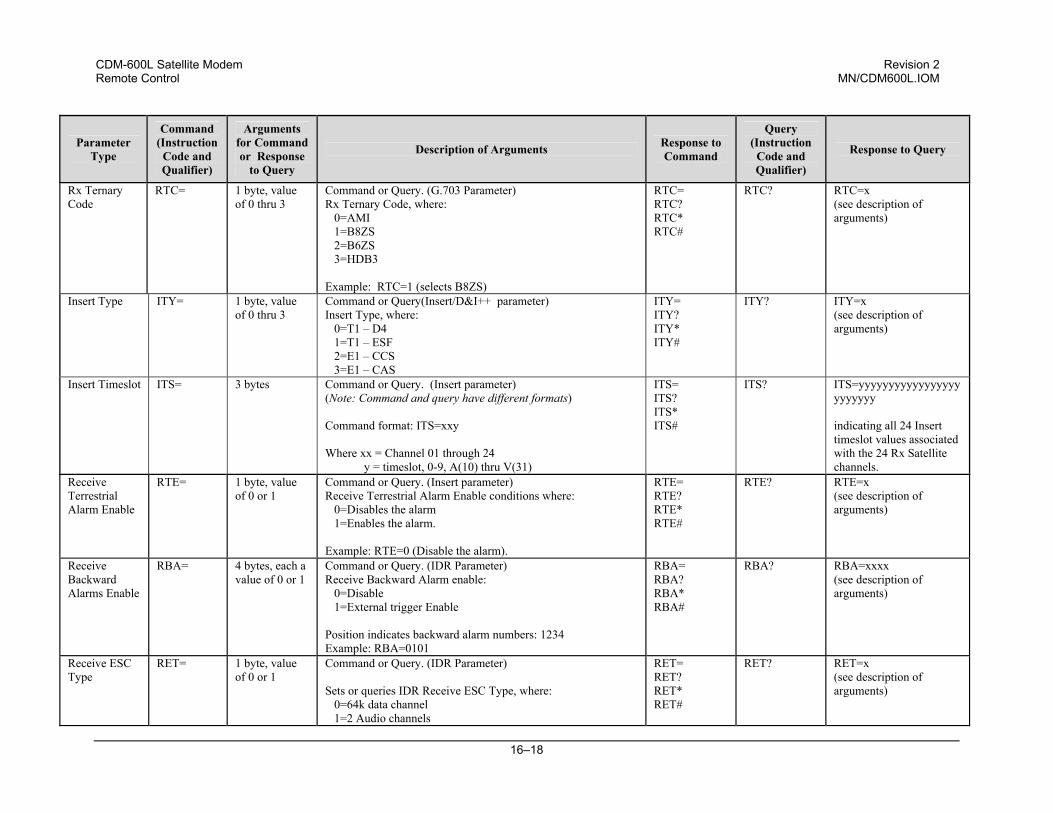
CDM-600L Satellite Modem Revision 2 Remote Control MN/CDM600L.IOM
16–18
Parameter Type
Command (Instruction
Code and Qualifier)
Arguments for Command or Response
to Query
Description of Arguments Response to Command
Query (Instruction
Code and Qualifier)
Response to Query
Rx Ternary Code
RTC=
1 byte, value of 0 thru 3
Command or Query. (G.703 Parameter) Rx Ternary Code, where: 0=AMI 1=B8ZS 2=B6ZS 3=HDB3 Example: RTC=1 (selects B8ZS)
RTC= RTC? RTC* RTC#
RTC?
RTC=x (see description of arguments)
Insert Type ITY= 1 byte, value of 0 thru 3
Command or Query(Insert/D&I++ parameter) Insert Type, where: 0=T1 – D4 1=T1 – ESF 2=E1 – CCS 3=E1 – CAS
ITY= ITY? ITY* ITY#
ITY? ITY=x (see description of arguments)
Insert Timeslot ITS= 3 bytes Command or Query. (Insert parameter) (Note: Command and query have different formats) Command format: ITS=xxy Where xx = Channel 01 through 24 y = timeslot, 0-9, A(10) thru V(31)
ITS= ITS? ITS* ITS#
ITS? ITS=yyyyyyyyyyyyyyyyyyyyyyyy indicating all 24 Insert timeslot values associated with the 24 Rx Satellite channels.
Receive Terrestrial Alarm Enable
RTE= 1 byte, value of 0 or 1
Command or Query. (Insert parameter) Receive Terrestrial Alarm Enable conditions where: 0=Disables the alarm 1=Enables the alarm. Example: RTE=0 (Disable the alarm).
RTE= RTE? RTE* RTE#
RTE? RTE=x (see description of arguments)
Receive Backward Alarms Enable
RBA= 4 bytes, each a value of 0 or 1
Command or Query. (IDR Parameter) Receive Backward Alarm enable: 0=Disable 1=External trigger Enable Position indicates backward alarm numbers: 1234 Example: RBA=0101
RBA= RBA? RBA* RBA#
RBA? RBA=xxxx (see description of arguments)
Receive ESC Type
RET= 1 byte, value of 0 or 1
Command or Query. (IDR Parameter) Sets or queries IDR Receive ESC Type, where: 0=64k data channel 1=2 Audio channels
RET= RET? RET* RET#
RET? RET=x (see description of arguments)
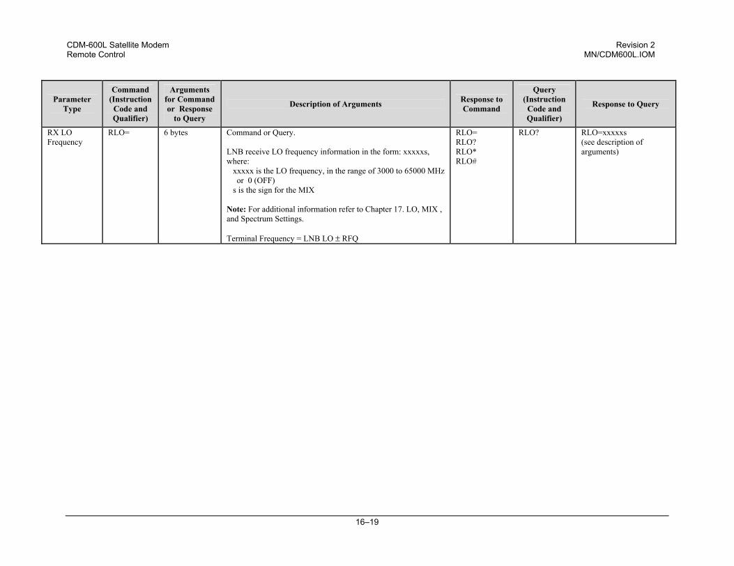
CDM-600L Satellite Modem Revision 2 Remote Control MN/CDM600L.IOM
16–19
Parameter Type
Command (Instruction
Code and Qualifier)
Arguments for Command or Response
to Query
Description of Arguments Response to Command
Query (Instruction
Code and Qualifier)
Response to Query
RX LO Frequency
RLO= 6 bytes Command or Query. LNB receive LO frequency information in the form: xxxxxs, where: xxxxx is the LO frequency, in the range of 3000 to 65000 MHz
or 0 (OFF) s is the sign for the MIX Note: For additional information refer to Chapter 17. LO, MIX , and Spectrum Settings. Terminal Frequency = LNB LO ± RFQ
RLO= RLO? RLO* RLO#
RLO? RLO=xxxxxs (see description of arguments)
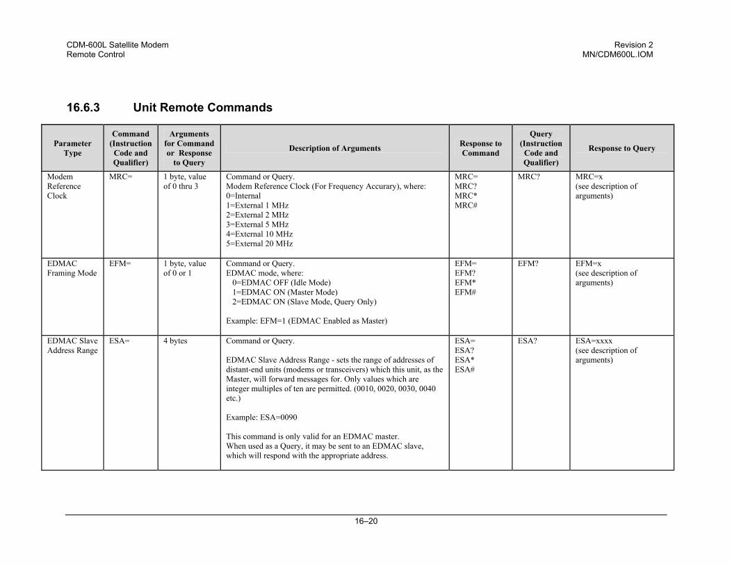
CDM-600L Satellite Modem Revision 2 Remote Control MN/CDM600L.IOM
16–20
16.6.3 Unit Remote Commands
Parameter Type
Command (Instruction
Code and Qualifier)
Arguments for Command or Response
to Query
Description of Arguments Response to Command
Query (Instruction
Code and Qualifier)
Response to Query
Modem Reference Clock
MRC= 1 byte, value of 0 thru 3
Command or Query. Modem Reference Clock (For Frequency Accurary), where: 0=Internal 1=External 1 MHz 2=External 2 MHz 3=External 5 MHz 4=External 10 MHz 5=External 20 MHz
MRC= MRC? MRC* MRC#
MRC? MRC=x (see description of arguments)
EDMAC Framing Mode
EFM= 1 byte, value of 0 or 1
Command or Query. EDMAC mode, where: 0=EDMAC OFF (Idle Mode) 1=EDMAC ON (Master Mode) 2=EDMAC ON (Slave Mode, Query Only) Example: EFM=1 (EDMAC Enabled as Master)
EFM= EFM? EFM* EFM#
EFM? EFM=x (see description of arguments)
EDMAC Slave Address Range
ESA= 4 bytes Command or Query. EDMAC Slave Address Range - sets the range of addresses of distant-end units (modems or transceivers) which this unit, as the Master, will forward messages for. Only values which are integer multiples of ten are permitted. (0010, 0020, 0030, 0040 etc.) Example: ESA=0090 This command is only valid for an EDMAC master. When used as a Query, it may be sent to an EDMAC slave, which will respond with the appropriate address.
ESA= ESA? ESA* ESA#
ESA? ESA=xxxx (see description of arguments)
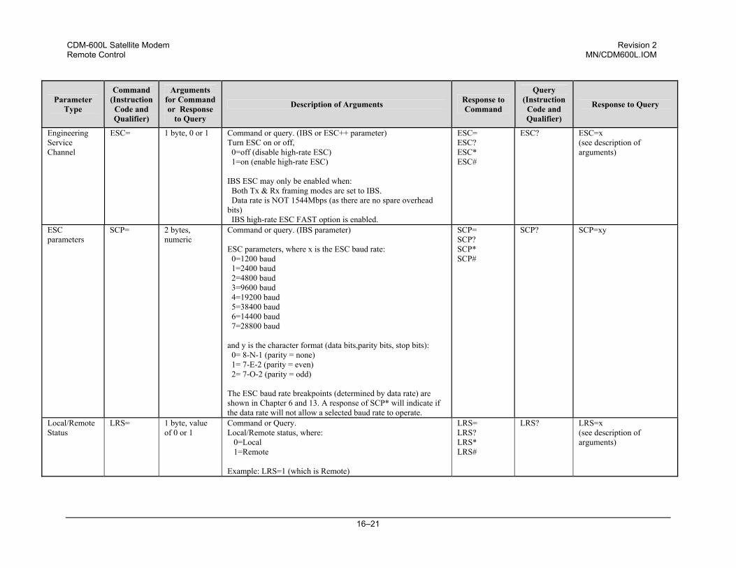
CDM-600L Satellite Modem Revision 2 Remote Control MN/CDM600L.IOM
16–21
Parameter Type
Command (Instruction
Code and Qualifier)
Arguments for Command or Response
to Query
Description of Arguments Response to Command
Query (Instruction
Code and Qualifier)
Response to Query
Engineering Service Channel
ESC= 1 byte, 0 or 1 Command or query. (IBS or ESC++ parameter) Turn ESC on or off, 0=off (disable high-rate ESC) 1=on (enable high-rate ESC) IBS ESC may only be enabled when: Both Tx & Rx framing modes are set to IBS. Data rate is NOT 1544Mbps (as there are no spare overhead bits) IBS high-rate ESC FAST option is enabled.
ESC= ESC? ESC* ESC#
ESC? ESC=x (see description of arguments)
ESC parameters
SCP= 2 bytes, numeric
Command or query. (IBS parameter) ESC parameters, where x is the ESC baud rate: 0=1200 baud 1=2400 baud 2=4800 baud 3=9600 baud 4=19200 baud 5=38400 baud 6=14400 baud 7=28800 baud and y is the character format (data bits,parity bits, stop bits): 0= 8-N-1 (parity = none) 1= 7-E-2 (parity = even) 2= 7-O-2 (parity = odd) The ESC baud rate breakpoints (determined by data rate) are shown in Chapter 6 and 13. A response of SCP* will indicate if the data rate will not allow a selected baud rate to operate.
SCP= SCP? SCP* SCP#
SCP? SCP=xy
Local/Remote Status
LRS= 1 byte, value of 0 or 1
Command or Query. Local/Remote status, where: 0=Local 1=Remote Example: LRS=1 (which is Remote)
LRS= LRS? LRS* LRS#
LRS? LRS=x (see description of arguments)
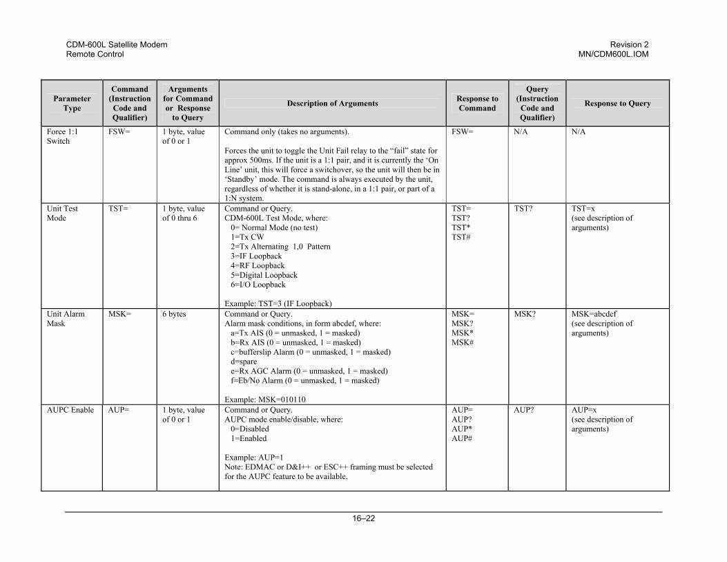
CDM-600L Satellite Modem Revision 2 Remote Control MN/CDM600L.IOM
16–22
Parameter Type
Command (Instruction
Code and Qualifier)
Arguments for Command or Response
to Query
Description of Arguments Response to Command
Query (Instruction
Code and Qualifier)
Response to Query
Force 1:1 Switch
FSW= 1 byte, value of 0 or 1
Command only (takes no arguments). Forces the unit to toggle the Unit Fail relay to the “fail” state for approx 500ms. If the unit is a 1:1 pair, and it is currently the ‘On Line’ unit, this will force a switchover, so the unit will then be in ‘Standby’ mode. The command is always executed by the unit, regardless of whether it is stand-alone, in a 1:1 pair, or part of a 1:N system.
FSW=
N/A N/A
Unit Test Mode
TST= 1 byte, value of 0 thru 6
Command or Query. CDM-600L Test Mode, where: 0= Normal Mode (no test) 1=Tx CW 2=Tx Alternating 1,0 Pattern 3=IF Loopback 4=RF Loopback 5=Digital Loopback 6=I/O Loopback Example: TST=3 (IF Loopback)
TST= TST? TST* TST#
TST? TST=x (see description of arguments)
Unit Alarm Mask
MSK= 6 bytes Command or Query. Alarm mask conditions, in form abcdef, where: a=Tx AIS (0 = unmasked, 1 = masked) b=Rx AIS (0 = unmasked, 1 = masked) c=bufferslip Alarm (0 = unmasked, 1 = masked) d=spare e=Rx AGC Alarm (0 = unmasked, 1 = masked) f=Eb/No Alarm (0 = unmasked, 1 = masked) Example: MSK=010110
MSK= MSK? MSK* MSK#
MSK? MSK=abcdef (see description of arguments)
AUPC Enable AUP=
1 byte, value of 0 or 1
Command or Query. AUPC mode enable/disable, where: 0=Disabled 1=Enabled Example: AUP=1 Note: EDMAC or D&I++ or ESC++ framing must be selected for the AUPC feature to be available.
AUP= AUP? AUP* AUP#
AUP?
AUP=x (see description of arguments)
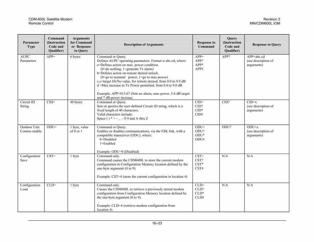
CDM-600L Satellite Modem Revision 2 Remote Control MN/CDM600L.IOM
16–23
Parameter Type
Command (Instruction
Code and Qualifier)
Arguments for Command or Response
to Query
Description of Arguments Response to Command
Query (Instruction
Code and Qualifier)
Response to Query
AUPC Parameters
APP=
6 bytes Command or Query. Defines AUPC operating parameters. Format is abc.cd, where: a=Defines action on max. power condition. (0=do nothing, 1=generate Tx alarm) b=Defines action on remote demod unlock. (0=go to nominal power, 1=go to max power) c.c=target Eb/No value, for remote demod, from 0.0 to 9.9 dB d =Max increase in Tx Power permitted, from 0.0 to 9.0 dB Example: APP=015.67 (Sets no alarm, max power, 5.6 dB target and 7 dB power increase.
APP= APP? APP* APP#
APP? APP=abc.cd (see description of arguments)
Circuit ID String
CID= 40 bytes Command or Query. Sets or queries the user-defined Circuit ID string, which is a fixed length of 40 characters. Valid characters include: Space ( ) * + – , . / 0 9 and A thru Z
CID= CID? CID* CID#
CID? CID=x (see description of arguments)
Outdoor Unit Comms enable
ODU= 1 byte, value of 0 or 1
Command or Query. Enables or disables communications, via the FSK link, with a compatible transceiver (ODU), where: 0=Disabled 1=Enabled Example: ODU=0 (Disabled)
ODU= ODU? ODU* ODU#
ODU? ODU=x (see description of arguments)
Configuration Save
CST= 1 byte Command only. Command causes the CDM600L to store the current modem configuration in Configuration Memory location defined by the one-byte argument (0 to 9). Example: CST=4 (store the current configuration in location 4)
CST= CST? CST* CST#
N/A N/A
Configuration Load
CLD= 1 byte Command only. Causes the CDM600L to retrieve a previously stored modem configuration from Configuration Memory location defined by the one-byte argument (0 to 9). Example: CLD=4 (retrieve modem configuration from location 4)
CLD= CLD? CLD* CLD#
N/A N/A
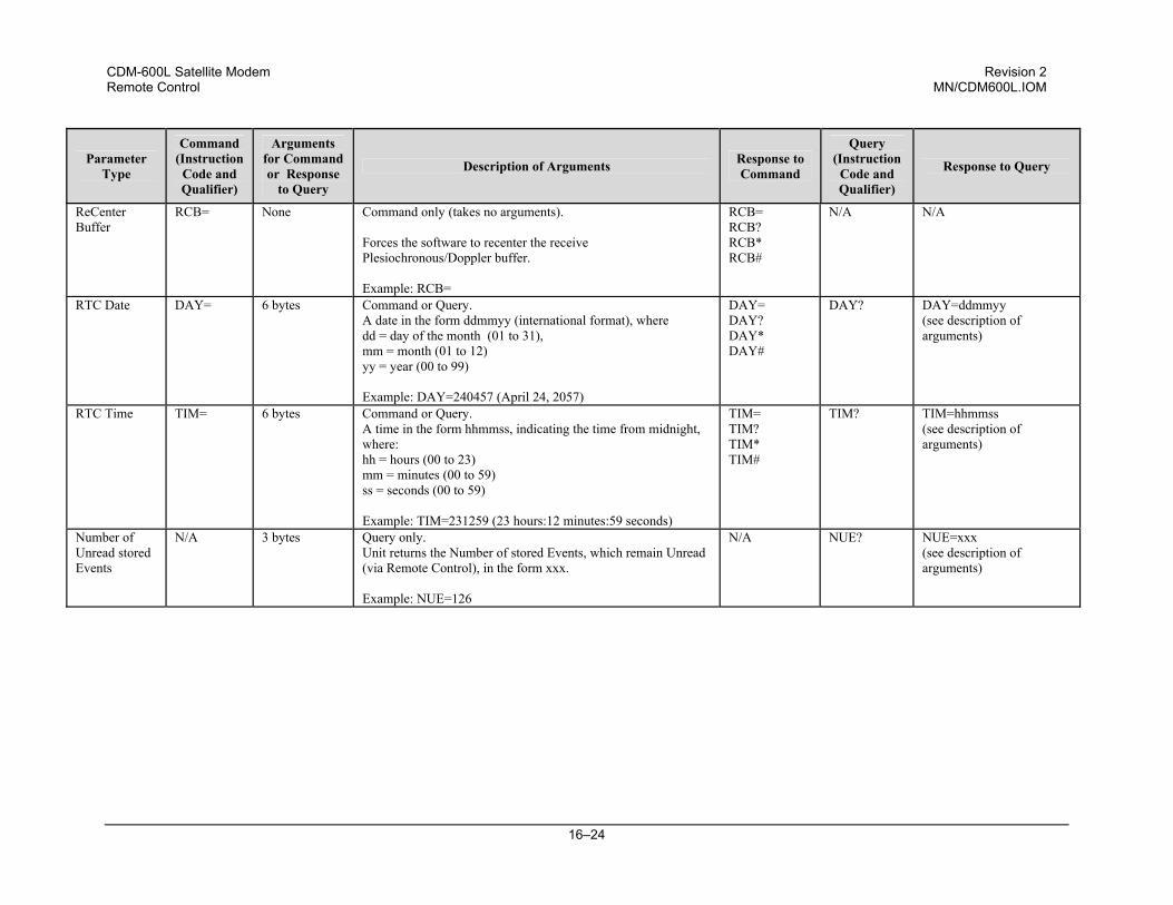
CDM-600L Satellite Modem Revision 2 Remote Control MN/CDM600L.IOM
16–24
Parameter Type
Command (Instruction
Code and Qualifier)
Arguments for Command or Response
to Query
Description of Arguments Response to Command
Query (Instruction
Code and Qualifier)
Response to Query
ReCenter Buffer
RCB= None Command only (takes no arguments). Forces the software to recenter the receive Plesiochronous/Doppler buffer. Example: RCB=
RCB= RCB? RCB* RCB#
N/A N/A
RTC Date DAY= 6 bytes Command or Query. A date in the form ddmmyy (international format), where dd = day of the month (01 to 31), mm = month (01 to 12) yy = year (00 to 99) Example: DAY=240457 (April 24, 2057)
DAY= DAY? DAY* DAY#
DAY? DAY=ddmmyy (see description of arguments)
RTC Time TIM= 6 bytes Command or Query. A time in the form hhmmss, indicating the time from midnight, where: hh = hours (00 to 23) mm = minutes (00 to 59) ss = seconds (00 to 59) Example: TIM=231259 (23 hours:12 minutes:59 seconds)
TIM= TIM? TIM* TIM#
TIM? TIM=hhmmss (see description of arguments)
Number of Unread stored Events
N/A 3 bytes Query only. Unit returns the Number of stored Events, which remain Unread (via Remote Control), in the form xxx. Example: NUE=126
N/A NUE? NUE=xxx (see description of arguments)
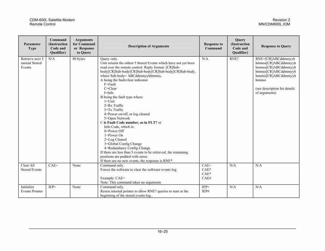
CDM-600L Satellite Modem Revision 2 Remote Control MN/CDM600L.IOM
16–25
Parameter Type
Command (Instruction
Code and Qualifier)
Arguments for Command or Response
to Query
Description of Arguments Response to Command
Query (Instruction
Code and Qualifier)
Response to Query
Retrieve next 5 unread Stored Events
N/A 80 bytes Query only. Unit returns the oldest 5 Stored Events which have not yet been read over the remote control. Reply format: [CR]Sub-body[CR]Sub-body[CR]Sub-body[CR]Sub-body[CR]Sub-body, where Sub-body= ABCddmmyyhhmmss, A being the fault/clear indicator. F=Fault C=Clear I=Info B being the fault type where: 1=Unit 2=Rx Traffic 3=Tx Traffic 4=Power on/off, or log cleared 5=Open Network C is Fault Code number, as in FLT? or Info Code, which is:
0=Power Off 1=Power On 2=Log Cleared 3=Global Config Change 4=Redundancy Config Change
If there are less than 5 events to be retrieved, the remaining positions are padded with zeros. If there are no new events, the response is RNE*.
N/A RNE? RNE=[CR]ABCddmmyyhhmmss[CR]ABCddmmyyhhmmss[CR]ABCddmmyyhhmmss[CR]ABCddmmyyhhmmss[CR]ABCddmmyyhhmmss (see description for details of arguments)
Clear All Stored Events
CAE= None Command only. Forces the software to clear the software events log. Example: CAE= Note: This command takes no arguments
CAE= CAE? CAE* CAE#
N/A N/A
Initialize Events Pointer
IEP= None Command only. Resets internal pointer to allow RNE? queries to start at the beginning of the stored events log.
IEP= IEP#
N/A N/A
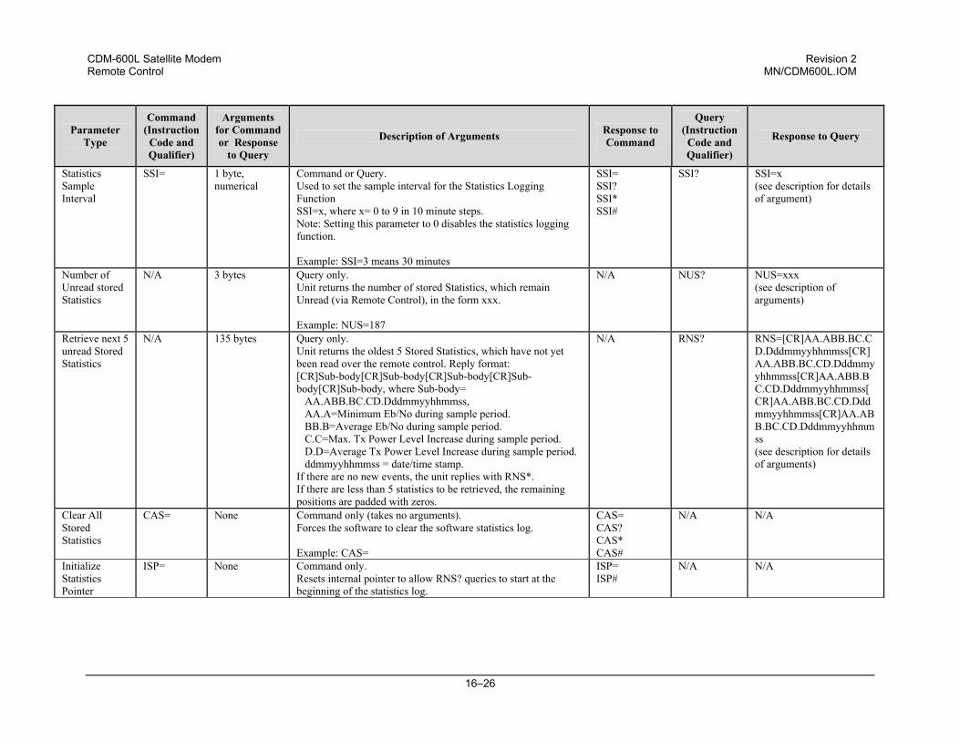
CDM-600L Satellite Modem Revision 2 Remote Control MN/CDM600L.IOM
16–26
Parameter Type
Command (Instruction
Code and Qualifier)
Arguments for Command or Response
to Query
Description of Arguments Response to Command
Query (Instruction
Code and Qualifier)
Response to Query
Statistics Sample Interval
SSI= 1 byte, numerical
Command or Query. Used to set the sample interval for the Statistics Logging Function SSI=x, where x= 0 to 9 in 10 minute steps. Note: Setting this parameter to 0 disables the statistics logging function. Example: SSI=3 means 30 minutes
SSI= SSI? SSI* SSI#
SSI? SSI=x (see description for details of argument)
Number of Unread stored Statistics
N/A 3 bytes Query only. Unit returns the number of stored Statistics, which remain Unread (via Remote Control), in the form xxx. Example: NUS=187
N/A NUS? NUS=xxx (see description of arguments)
Retrieve next 5 unread Stored Statistics
N/A 135 bytes Query only. Unit returns the oldest 5 Stored Statistics, which have not yet been read over the remote control. Reply format: [CR]Sub-body[CR]Sub-body[CR]Sub-body[CR]Sub-body[CR]Sub-body, where Sub-body= AA.ABB.BC.CD.Dddmmyyhhmmss, AA.A=Minimum Eb/No during sample period. BB.B=Average Eb/No during sample period. C.C=Max. Tx Power Level Increase during sample period. D.D=Average Tx Power Level Increase during sample period. ddmmyyhhmmss = date/time stamp. If there are no new events, the unit replies with RNS*. If there are less than 5 statistics to be retrieved, the remaining positions are padded with zeros.
N/A RNS? RNS=[CR]AA.ABB.BC.CD.Dddmmyyhhmmss[CR]AA.ABB.BC.CD.Dddmmyyhhmmss[CR]AA.ABB.BC.CD.Dddmmyyhhmmss[CR]AA.ABB.BC.CD.Dddmmyyhhmmss[CR]AA.ABB.BC.CD.Dddmmyyhhmmss (see description for details of arguments)
Clear All Stored Statistics
CAS= None Command only (takes no arguments). Forces the software to clear the software statistics log. Example: CAS=
CAS= CAS? CAS* CAS#
N/A N/A
Initialize Statistics Pointer
ISP= None Command only. Resets internal pointer to allow RNS? queries to start at the beginning of the statistics log.
ISP= ISP#
N/A N/A
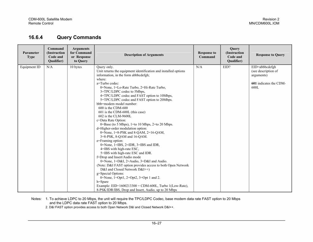
CDM-600L Satellite Modem Revision 2 Remote Control MN/CDM600L.IOM
16–27
16.6.4 Query Commands
Parameter Type
Command (Instruction
Code and Qualifier)
Arguments for Command or Response
to Query
Description of Arguments Response to Command
Query (Instruction
Code and Qualifier)
Response to Query
Equipment ID N/A 10 bytes Query only. Unit returns the equipment identification and installed options information, in the form abbbcdefgh; where: a=Turbo codec: 0=None, 1=Lo-Rate Turbo, 2=Hi-Rate Turbo, 3=TPC/LDPC codec to 5Mbps, 4=TPC/LDPC codec and FAST option to 10Mbps, 5=TPC/LDPC codec and FAST option to 20Mbps. bbb=modem model number: 600 is the CDM-600 601 is the CDM-600L (this case) 602 is the CLM-9600L c=Data Rate Option: 0=Base (to 5 Mbps), 1=to 10 Mbps, 2=to 20 Mbps. d=Higher-order modulation option: 0=None, 1=8-PSK and 8-QAM, 2=16-QAM, 3=8-PSK, 8-QAM and 16-QAM. e=Framing option: 0=None, 1=IBS, 2=IDR, 3=IBS and IDR, 4=IBS with high-rate ESC, 5=IBS with high-rate ESC and IDR.f=Drop and Insert/Audio mode 0=None, 1=D&I, 2=Audio, 3=D&I and Audio. (Note: D&I FAST option provides access to both Open Network
D&I and Closed Network D&I++) g=Special Options: 0=None, 1=Opt1, 2=Opt2, 3=Opt 1 and 2. h=Spare Example: EID=1600213300 = CDM-600L, Turbo 1(Low-Rate), 8-PSK/IDR/IBS, Drop and Insert, Audio, up to 20 Mbps
N/A EID? EID=abbbcdefgh (see description of arguments) 601 indicates the CDM-600L
Notes: 1. To achieve LDPC to 20 Mbps, the unit will require the TPC/LDPC Codec, base modem data rate FAST option to 20 Mbps and the LDPC data rate FAST option to 20 Mbps. 2. D&I FAST option provides access to both Open Network D&I and Closed Network D&I++.
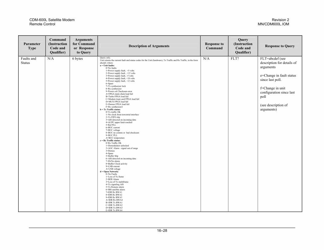
CDM-600L Satellite Modem Revision 2 Remote Control MN/CDM600L.IOM
16–28
Parameter Type
Command (Instruction
Code and Qualifier)
Arguments for Command or Response
to Query
Description of Arguments Response to Command
Query (Instruction
Code and Qualifier)
Response to Query
Faults and Status
N/A 6 bytes Query only. Unit returns the current fault and status codes for the Unit (hardware), Tx Traffic and Rx Traffic, in the form abcdef, where: a = Unit faults:
0=No faults 1=Power supply fault, +5 volts 2=Power supply fault , +12 volts 3=Power supply fault, –5 volts 4=Power supply fault, +18 volts 5=Power supply fault, –12 volts 6=Spare 7=Tx synthesizer lock 8=Rx synthesizer 9=Power cal Checksum error A=FPGA main chain load fail B=Turbo FPGA load fail C=Modem (top) card FPGA load fail D=MUX FPGA load fail E=Demux FPGA load fail F=Rx synthesizer2
b = Tx Traffic status: 0=Tx traffic OK 1=No clock from terrestrial interface 2=Tx FIFO slip 3=AIS detected on incoming data 4=AUPC upper limit reached 5=Ref PLL 6=BUC current 7=BUC voltage 8=BUC no comms or bad checksum 9=BUC PLL A=BUC temperature
c = Rx Traffic status: 0=Rx Traffic OK 1=Demodulator unlocked 2=AGC Alarm - signal out of range 3=Demux 4=Spare 5=Buffer Slip 6=AIS detected on incoming data 7=Eb/No alarm 8=Buffer Clock activity 9=LNB current A=LNB voltage
d = Open Network: 0=No Faults 1=Loss of Tx frame 2=BER Alarm 3=Loss of Tx multiframe 4=Tx signaling AIS 5=Tx Remote alarm 6=IBS satellite alarm 7=IDR Rx BWA1 8=IDR Rx BWA2 9=IDR Rx BWA3 A=IDR Rx BWA4 B=IDR Tx BWA1 C=IDR Tx BWA2 D=IDR Tx BWA3 E=IDR Tx BWA4
N/A FLT? FLT=abcdef (see description for details of arguments e=Change in fault status since last poll. f=Change in unit configuration since last poll (see description of arguments)
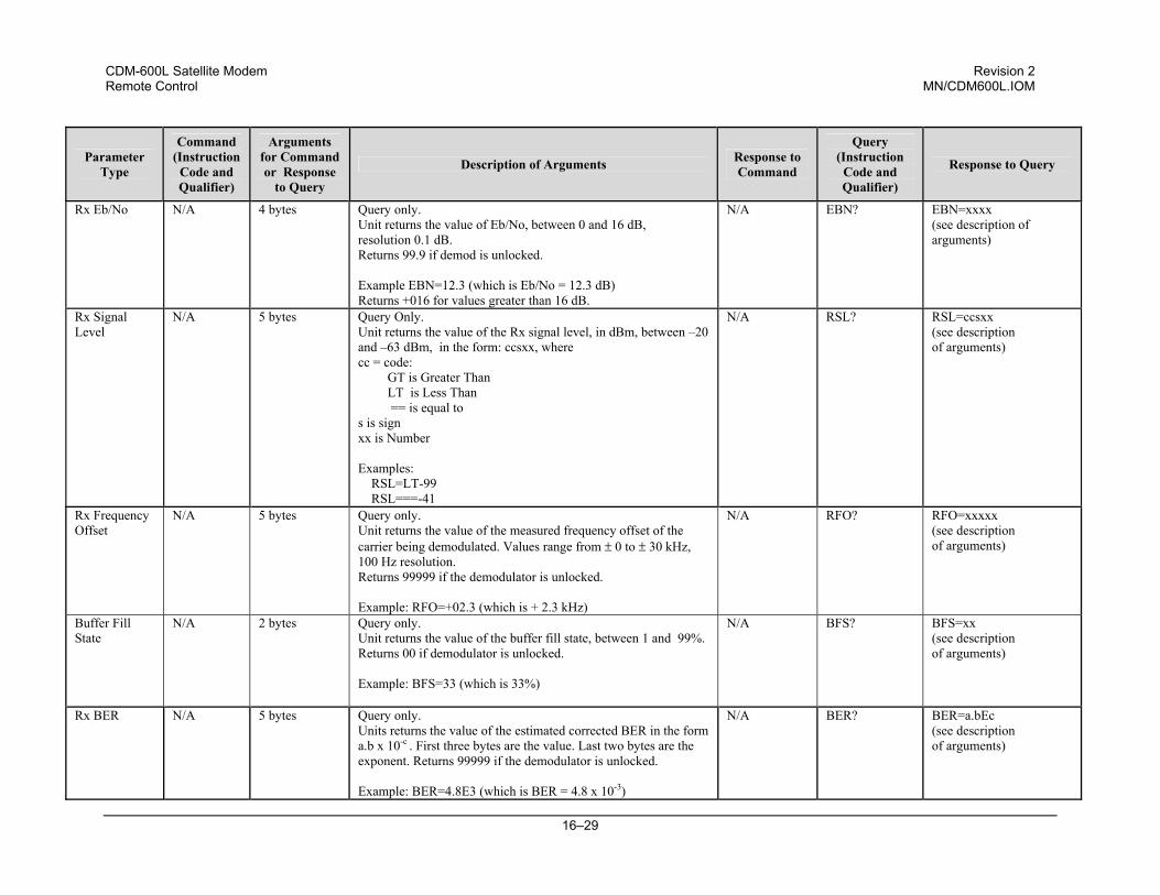
CDM-600L Satellite Modem Revision 2 Remote Control MN/CDM600L.IOM
16–29
Parameter Type
Command (Instruction
Code and Qualifier)
Arguments for Command or Response
to Query
Description of Arguments Response to Command
Query (Instruction
Code and Qualifier)
Response to Query
Rx Eb/No N/A 4 bytes Query only. Unit returns the value of Eb/No, between 0 and 16 dB, resolution 0.1 dB. Returns 99.9 if demod is unlocked. Example EBN=12.3 (which is Eb/No = 12.3 dB) Returns +016 for values greater than 16 dB.
N/A EBN? EBN=xxxx (see description of arguments)
Rx Signal Level
N/A 5 bytes Query Only. Unit returns the value of the Rx signal level, in dBm, between –20 and –63 dBm, in the form: ccsxx, where cc = code:
GT is Greater Than LT is Less Than == is equal to
s is sign xx is Number Examples: RSL=LT-99 RSL===-41
N/A RSL? RSL=ccsxx (see description of arguments)
Rx Frequency Offset
N/A 5 bytes Query only. Unit returns the value of the measured frequency offset of the carrier being demodulated. Values range from ± 0 to ± 30 kHz, 100 Hz resolution. Returns 99999 if the demodulator is unlocked. Example: RFO=+02.3 (which is + 2.3 kHz)
N/A RFO? RFO=xxxxx (see description of arguments)
Buffer Fill State
N/A 2 bytes Query only. Unit returns the value of the buffer fill state, between 1 and 99%. Returns 00 if demodulator is unlocked. Example: BFS=33 (which is 33%)
N/A BFS? BFS=xx (see description of arguments)
Rx BER N/A 5 bytes Query only. Units returns the value of the estimated corrected BER in the form a.b x 10-c . First three bytes are the value. Last two bytes are the exponent. Returns 99999 if the demodulator is unlocked. Example: BER=4.8E3 (which is BER = 4.8 x 10⁻³)
N/A BER? BER=a.bEc (see description of arguments)
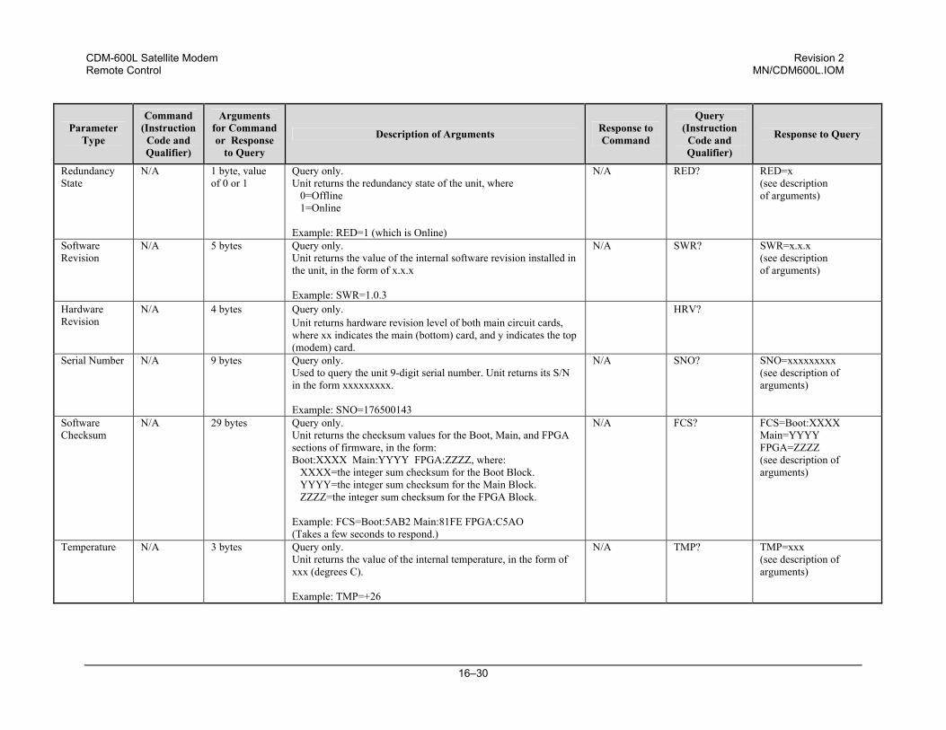
CDM-600L Satellite Modem Revision 2 Remote Control MN/CDM600L.IOM
16–30
Parameter Type
Command (Instruction
Code and Qualifier)
Arguments for Command or Response
to Query
Description of Arguments Response to Command
Query (Instruction
Code and Qualifier)
Response to Query
Redundancy State
N/A 1 byte, value of 0 or 1
Query only. Unit returns the redundancy state of the unit, where 0=Offline 1=Online Example: RED=1 (which is Online)
N/A RED? RED=x (see description of arguments)
Software Revision
N/A 5 bytes Query only. Unit returns the value of the internal software revision installed in the unit, in the form of x.x.x Example: SWR=1.0.3
N/A SWR? SWR=x.x.x (see description of arguments)
Hardware Revision
N/A 4 bytes Query only. Unit returns hardware revision level of both main circuit cards, where xx indicates the main (bottom) card, and y indicates the top (modem) card.
HRV?
Serial Number N/A 9 bytes Query only. Used to query the unit 9-digit serial number. Unit returns its S/N in the form xxxxxxxxx. Example: SNO=176500143
N/A SNO? SNO=xxxxxxxxx (see description of arguments)
Software Checksum
N/A 29 bytes Query only. Unit returns the checksum values for the Boot, Main, and FPGA sections of firmware, in the form: Boot:XXXX Main:YYYY FPGA:ZZZZ, where: XXXX=the integer sum checksum for the Boot Block. YYYY=the integer sum checksum for the Main Block. ZZZZ=the integer sum checksum for the FPGA Block. Example: FCS=Boot:5AB2 Main:81FE FPGA:C5AO (Takes a few seconds to respond.)
N/A FCS? FCS=Boot:XXXX Main=YYYY FPGA=ZZZZ (see description of arguments)
Temperature N/A 3 bytes Query only. Unit returns the value of the internal temperature, in the form of xxx (degrees C). Example: TMP=+26
N/A TMP? TMP=xxx (see description of arguments)
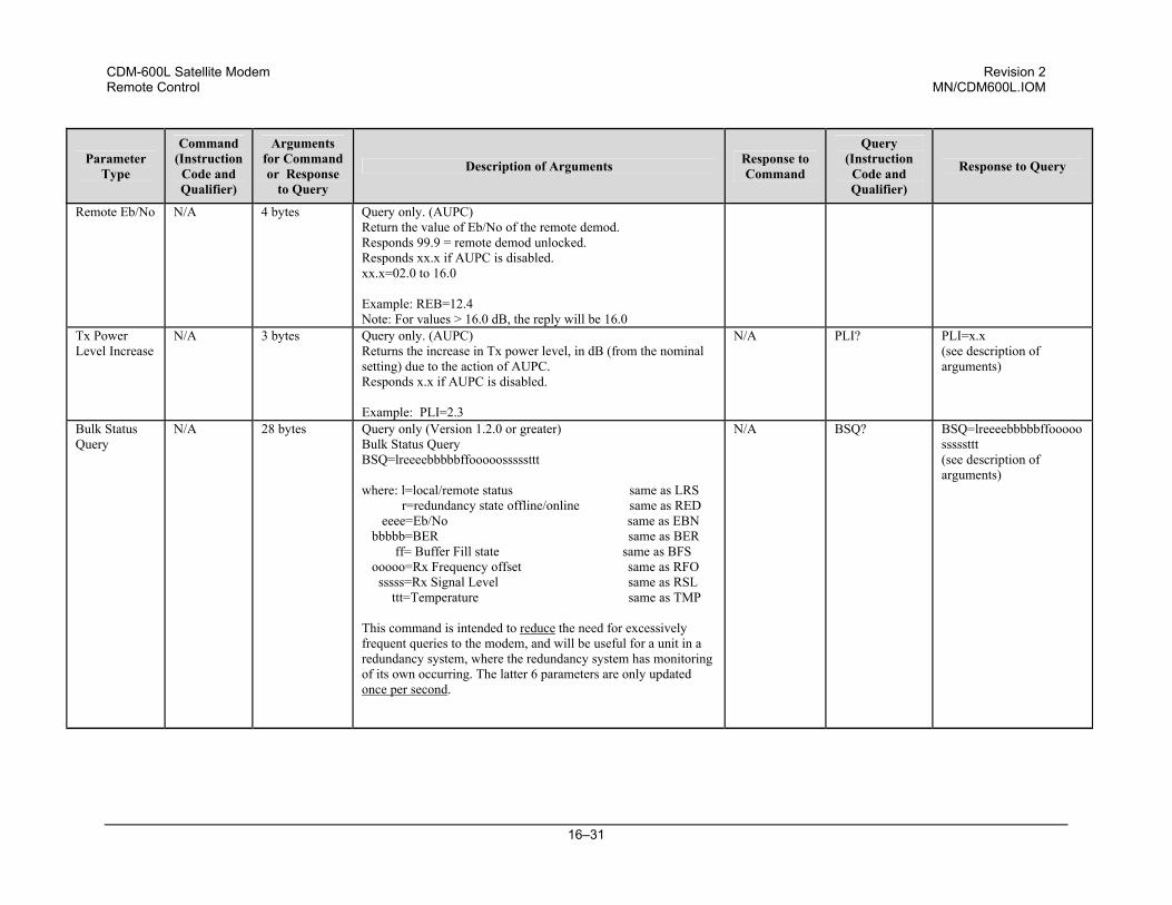
CDM-600L Satellite Modem Revision 2 Remote Control MN/CDM600L.IOM
16–31
Parameter Type
Command (Instruction
Code and Qualifier)
Arguments for Command or Response
to Query
Description of Arguments Response to Command
Query (Instruction
Code and Qualifier)
Response to Query
Remote Eb/No N/A 4 bytes Query only. (AUPC) Return the value of Eb/No of the remote demod. Responds 99.9 = remote demod unlocked. Responds xx.x if AUPC is disabled. xx.x=02.0 to 16.0 Example: REB=12.4 Note: For values > 16.0 dB, the reply will be 16.0
Tx Power Level Increase
N/A 3 bytes Query only. (AUPC) Returns the increase in Tx power level, in dB (from the nominal setting) due to the action of AUPC. Responds x.x if AUPC is disabled. Example: PLI=2.3
N/A PLI? PLI=x.x (see description of arguments)
Bulk Status Query
N/A 28 bytes Query only (Version 1.2.0 or greater) Bulk Status Query BSQ=lreeeebbbbbffooooosssssttt where: l=local/remote status same as LRS r=redundancy state offline/online same as RED eeee=Eb/No same as EBN bbbbb=BER same as BER ff= Buffer Fill state same as BFS ooooo=Rx Frequency offset same as RFO sssss=Rx Signal Level same as RSL ttt=Temperature same as TMP This command is intended to reduce the need for excessively frequent queries to the modem, and will be useful for a unit in a redundancy system, where the redundancy system has monitoring of its own occurring. The latter 6 parameters are only updated once per second.
N/A BSQ? BSQ=lreeeebbbbbffooooosssssttt (see description of arguments)
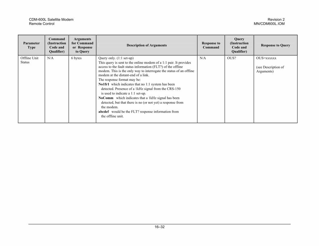
CDM-600L Satellite Modem Revision 2 Remote Control MN/CDM600L.IOM
16–32
Parameter Type
Command (Instruction
Code and Qualifier)
Arguments for Command or Response
to Query
Description of Arguments Response to Command
Query (Instruction
Code and Qualifier)
Response to Query
Offline Unit Status
N/A 6 bytes Query only. (1:1 set-up) This query is sent to the online modem of a 1:1 pair. It provides access to the fault status information (FLT?) of the offline modem. This is the only way to interrogate the status of an offline modem at the distant-end of a link. The response format may be: No1fr1 which indicates that no 1:1 system has been detected. Presence of a 1kHz signal from the CRS-150 is used to indicate a 1:1 set-up. NoComm which indicates that a 1kHz signal has been detected, but that there is no (or not yet) a response from the modem. abcdef would be the FLT? response information from the offline unit.
N/A OUS? OUS=xxxxxx (see Description of Arguments)
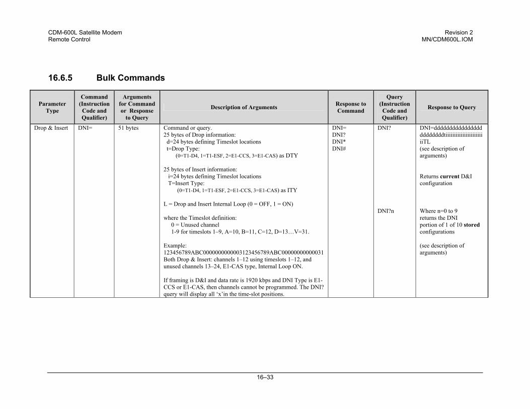
CDM-600L Satellite Modem Revision 2 Remote Control MN/CDM600L.IOM
16–33
16.6.5 Bulk Commands
Parameter Type
Command (Instruction
Code and Qualifier)
Arguments for Command or Response
to Query
Description of Arguments Response to Command
Query (Instruction
Code and Qualifier)
Response to Query
Drop & Insert DNI= 51 bytes Command or query. 25 bytes of Drop information: d=24 bytes defining Timeslot locations t=Drop Type: (0=T1-D4, 1=T1-ESF, 2=E1-CCS, 3=E1-CAS) as DTY 25 bytes of Insert information:
i=24 bytes defining Timeslot locations T=Insert Type: (0=T1-D4, 1=T1-ESF, 2=E1-CCS, 3=E1-CAS) as ITY
L = Drop and Insert Internal Loop (0 = OFF, 1 = ON) where the Timeslot definition: 0 = Unused channel 1-9 for timeslots 1–9, A=10, B=11, C=12, D=13…V=31. Example: 123456789ABC0000000000003123456789ABC00000000000031 Both Drop & Insert: channels 1–12 using timeslots 1–12, and unused channels 13–24, E1-CAS type, Internal Loop ON. If framing is D&I and data rate is 1920 kbps and DNI Type is E1-CCS or E1-CAS, then channels cannot be programmed. The DNI? query will display all ‘x’in the time-slot positions.
DNI= DNI? DNI* DNI#
DNI? DNI?n
DNI=ddddddddddddddddddddddddtiiiiiiiiiiiiiiiiiiiiiiiiTL (see description of arguments) Returns current D&I configuration Where n=0 to 9 returns the DNI portion of 1 of 10 stored configurations (see description of arguments)
CDM-600L Satellite Modem Revision 2 Remote Control MN/CDM600L.IOM
16–34
Parameter Type
Command (Instruction
Code and Qualifier)
Arguments for Command or Response
to Query
Description of Arguments Response to Command
Query (Instruction
Code and Qualifier)
Response to Query
Global Configuration
MGC= 118 bytes, with numerical entries, fixed values and delimiters
Command or Query.Global Configuration of CDM600L, in the form: FFFFFFFFDDDDD.DDDGYRMVSPP.PBaaa.aaCXIKNWffffffffddddd.dddgyrmvswwctt.tbbbbbiknWOEEEETAAAAAAZeLQUHHHHhhhhJJJJjjjjKkpqux, where: FFFFFFFF = Tx Frequency as TFQ* DDDDD.DDD = Tx Data Rate same as TDR G = Tx FEC Type same as TFT Y = Tx Reed-Solomon type same as TRS R = Tx FEC Rate same as TCR M = Tx Modulation type same as TMD V = Tx Spectrum Inversion same as TSI S = Tx Scrambler state same as TSC PP.P = Tx Power Level same as TPL B = AUPC Enable same as AUP aaa.aa = AUPC parameter setup same as APP C = Tx Clock Source same as TCK X = Tx Carrier State same as TXO I = Tx Interface Type same as TIT K = Tx Ternary Code same as TTC N = Tx Framing Mode same as TFMW=Spare byte ffffffff = Rx Frequency as RFQ* ddddd.ddd = Rx Data Rate same as RDR g = Rx FEC Type same as RFT y = Rx Reed-Solomon type same as RRS r = Rx FEC Rate same as RCR m = Rx Modulation Type same as RMD v = Rx Spectrum Inversion same as RSI s = Rx Scrambler state same as RDS ww = Rx Sweep Width same as RSW c = Rx Clock Source same as RCK tt.t = Eb/No Alarm Point same as EBA bbbbb = Rx Buffer Size same as RBS i = Rx Interface Type same as RIT k = Rx Ternary Code same as RTC n = Rx Framing Mode same as RFM W=Spare byte O = Unit EDMAC Mode same as EFM (or ESC when in IBS mode) EEEE = EDMAC Address same as ESA (or SCP when in IBS mode: xy00) T = Unit test Mode same as TST (Read only) AAAAAA = Unit Alarm Mask same as MSK Z=Modem Reference same as MRCe = Statistics Sampling Interval same as SSI L = Rx Terrestrial Alarm Enable same as RTE Q = Tx Terrestrial Alarm Enable same as TTA U = ODU FSK Comms Enable same as ODU HHHH = Transmit Backward Alarms same as TBA hhhh =Receive Backward Alarms same as RBA JJJJ = Tx Audio volume same as TVL jjjj = Rx Audio volume same as RVL K=Drop Type, k=Insert Type same as DTY, ITY p=Tx ESC Type, q=Rx ESC Type same as TET, RET u = Invert Tx Data same as ITD x = Invert Rx Data same as IRD
MGC= MGC? MGC* MGC#
MGC? MGC?n
MGC=FFFFFFFFDDDDD.DDDGYRMVSPP.PBaaa.aaCXIKNWffffffffddddd.dddgyrmvswwctt.tbbbbbiknWOEEEETAAAAAAZeLQUHHHHhhhhJJJJjjjjKkpqux (see description of arguments) Returns current configuration Where n=0 to 9 returns the MGC portion of 1 of 10 stored configurations (see description of
arguments) * Same as TFQ or RFQ, but with the period omitted
CDM-600L Satellite Modem Revision 2 Remote Control MN/CDM600L.IOM
16–35
Parameter Type
Command (Instruction
Code and Qualifier)
Arguments for Command or Response
to Query
Description of Arguments Response to Command
Query (Instruction
Code and Qualifier)
Response to Query
OGC Outdoor Unit Global Copy
OGC= 50 Bytes Command or Query ODU Global Configuration of CDM-600L in the form: aabcdemm:ssgggghhhhpp.pijklllnnnFFFFFSfffffsxxxxxx, where:
OGC= OGC? OGC* OGC#
OGC? OGC=aabcdemm:ssgggghhhhpp.pijklllnnnFFFFFSfffffsxxxxxx (see description of arguments)
aa=BUC Address b=BUC Tx Output Power Enable c=BUC Power Leveling Enable d=BUC Power Supply State e=BUC 10MHz Reference State mm:ss=BUC Carrier Output Delay gggg=BUC Low Alarm Limit hhhh=BUC High Alarm Limit pp.p=Output Target Power i=LNB Voltage j=LNB Power State k=LNB 10MHz Reference lll=LNB Low Alarm Limit nnn=LNB High Alarm Limit FFFFFS=TX LO Frequency fffffs=RX LO Frequency xxxxxx=Spare Bytes A response to a query will fill any unavailable parameters with xxx.
same as OAD same as OOP same as OPL same as ODP same as ODR same as OOD same as ODL same as ODH same as OTP same as LNV same as LNB same as LNR same as LNL same as LNH same as TLO same as RLO
OGC?n
Returns current OGC configuration Where n=0 to 9 returns the OGC portion of 1 of 10 stored configurations (see description of arguments)
Note: The following codes are used in the ‘Response to Command’ column: = Message ok ? Received ok, but invalid arguments found * Message ok, but not permitted in current mode
# Message ok, but unit is not in Remote mode ~ Time out of an EDMAC pass-through message
CDM-600L Satellite Modem Revision 2 Remote Control MN/CDM600L.IOM
16–36
16.6.6 BUC Commands
Parameter Type
Command (Instruction
Code and Qualifier)
Arguments for Command or Response
to Query
Description of Arguments Response to Command
Query (Instruction
Code and Qualifier)
Response to Query
BUC Power enable
ODP= 1 byte, value of 0 or 1
Command or Query. 0=Disable BUC DC Power Supply 1=Enable BUC DC Power Supply
ODP= ODP? ODP* ODP#
ODP? ODP=x (see description of arguments)
BUC 10 MHz Reference
ODR= 1 byte Command or Query. Where x is either 0(OFF) or 1(ON).
ODR= ODR? ODR* ODR#
ODR? ODR=x (see description of arguments)
BUC Low Current Limit
ODL= 4 bytes Command or Query. BUC Low Current Limit, a value between 0 and 4000mA, in 100mA increments.
ODL= ODL? ODL* ODL#
ODL? ODL=xxxx (see description of arguments)
BUC High Current Limit
ODH= 4 bytes Command or Query. BUC High Current Limit, a value between 0 and 4000mA, in 100mA increments.
ODH= ODH? ODH* ODH#
ODH? ODH=xxxx (see description of arguments)
BUC Carrier Output Delay
OOD= 5 bytes Command or Query. Power-up delay for the BUC to warm-up prior to the TX Carrier On, where mm=minutes (0–20) ss = seconds (0–59)
OOD= OOD? OOD* OOD#
OOD? OOD=mm:ss (see description of arguments)
BUC Address OAD= 1 byte, value of 1 to 15
Command or Query. BUC Address, in the form: xx, where xx is between 1 and 15. Note: This command is only valid when the FSK and BUC power are enabled.
OAD= OAD? OAD* OAD#
OAD? OAD=xx (see description of arguments)
BUC Output Power Enable
OOP= 1 byte, value of 0 or 1
Command or Query. BUC Tx Carrier Output Power, either 0(OFF) or 1(ON). Note: This command is only valid when the FSK and BUC power are enabled.
OOP= OOP? OOP* OOP#
OOP? OOP=x (see description of arguments)
CDM-600L Satellite Modem Revision 2 Remote Control MN/CDM600L.IOM
16–37
Parameter Type
Command (Instruction
Code and Qualifier)
Arguments for Command or Response
to Query
Description of Arguments Response to Command
Query (Instruction
Code and Qualifier)
Response to Query
BUC Power Leveling Enable
OPL= 1 byte, value of 0 or 1
Command or Query. Indicates BUC Power Leveling, either 0 (Leveling Off) or 1 (Leveling On). Note: This command is only valid when the FSK and BUC power are enabled.
OPL= OPL? OPL* OPL#
OPL? OPL=x (see description of arguments)
BUC Target Power
OTP= 4 bytes Query only. Target level for leveling control of output power (negative sign is assumed). Command is only used between CDM-600L units in a 1:1 system. Format: xx.x Range: 0 to -40 dBm
OTP= OTP? OTP* OTP#
OTP? OTP=xx.x (see description of arguments)
BUC Current N/A 4 bytes Query only. Indicates the value of the BUC Current, in the form: xxxx, where xxxx is between 0 and 9999, units mA. If not available, response is 0000.
N/A ODC? ODC=xxxx (see description of arguments)
BUC Voltage N/A 4 bytes Query only. Indicates the value of the BUC Voltage, in the form: xx.x, where xx.x is between 0 and 64.0, units in volts.
N/A ODV? ODV=xx.x (see description of arguments)
BUC Output Power Level
N/A 4 bytes Query only. BUC Output Power Level, where xx.x is the value in dBm. Example: OOL=37.4 Returns xxxx when FSK and BUC power are not enabled.
N/A OOL? OOL=xx.x (see description of arguments)
BUC Temperature
N/A 4 bytes Query only. BUC temperature, in the form: sxxx, where s = sign xxx = number Note: This query is only valid when the FSK and BUC power are turned On.
N/A ODT? ODT=sxxx (see description of arguments)
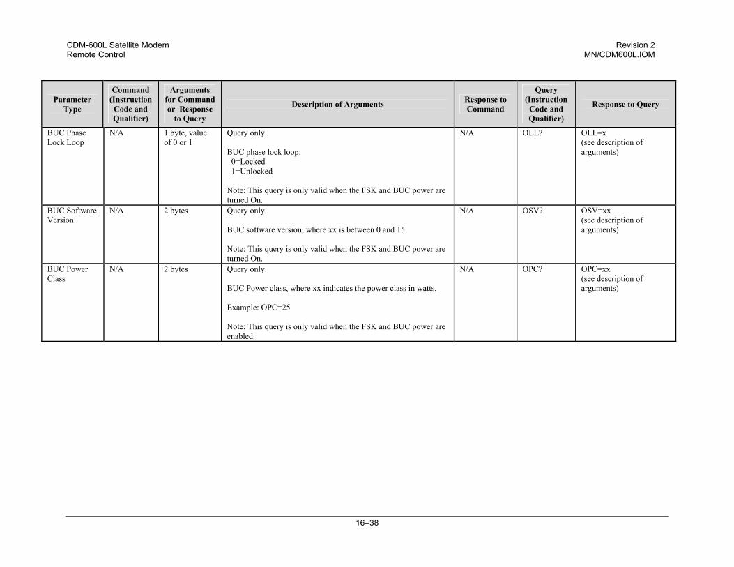
CDM-600L Satellite Modem Revision 2 Remote Control MN/CDM600L.IOM
16–38
Parameter Type
Command (Instruction
Code and Qualifier)
Arguments for Command or Response
to Query
Description of Arguments Response to Command
Query (Instruction
Code and Qualifier)
Response to Query
BUC Phase Lock Loop
N/A 1 byte, value of 0 or 1
Query only. BUC phase lock loop: 0=Locked 1=Unlocked Note: This query is only valid when the FSK and BUC power are turned On.
N/A OLL? OLL=x (see description of arguments)
BUC Software Version
N/A 2 bytes Query only. BUC software version, where xx is between 0 and 15. Note: This query is only valid when the FSK and BUC power are turned On.
N/A OSV? OSV=xx (see description of arguments)
BUC Power Class
N/A 2 bytes Query only. BUC Power class, where xx indicates the power class in watts. Example: OPC=25 Note: This query is only valid when the FSK and BUC power are enabled.
N/A OPC? OPC=xx (see description of arguments)
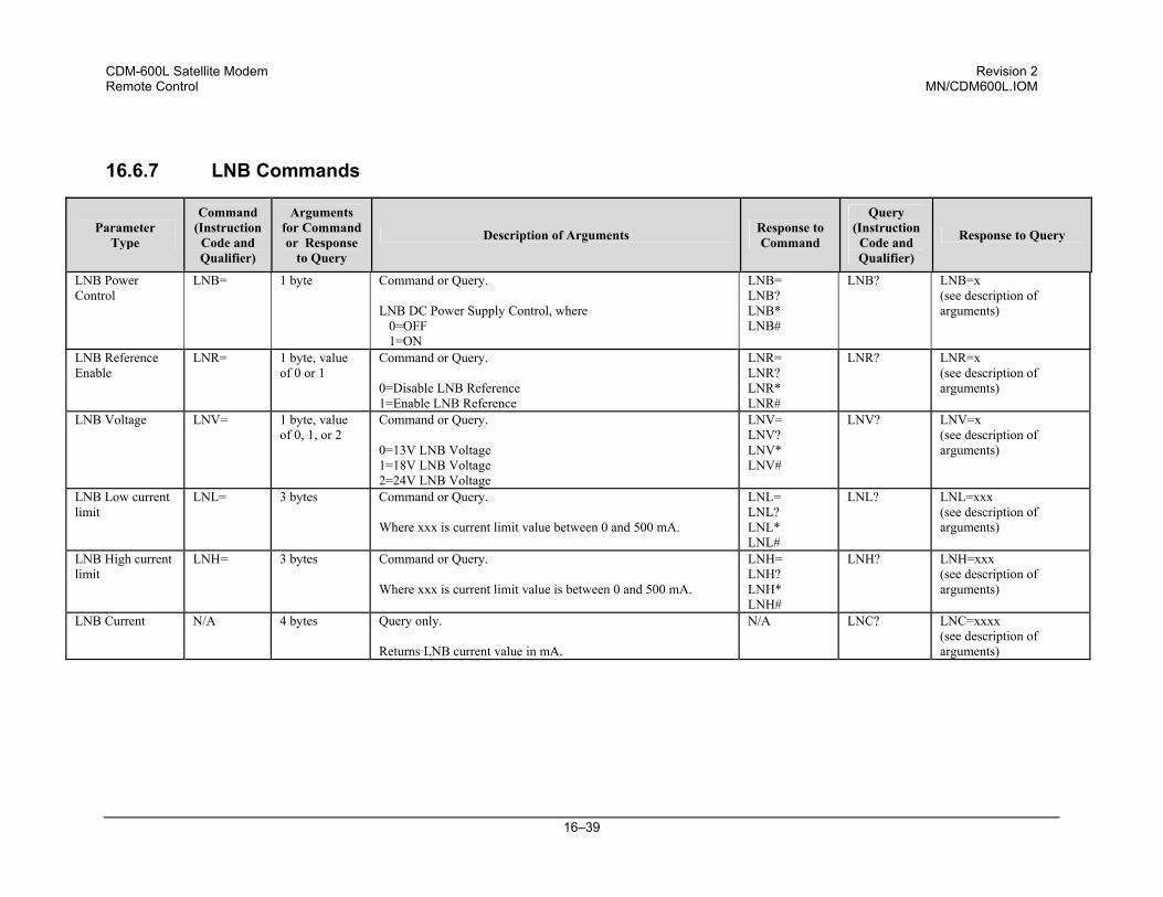
CDM-600L Satellite Modem Revision 2 Remote Control MN/CDM600L.IOM
16–39
16.6.7 LNB Commands
Parameter Type
Command (Instruction
Code and Qualifier)
Arguments for Command or Response
to Query
Description of Arguments Response to Command
Query (Instruction
Code and Qualifier)
Response to Query
LNB Power Control
LNB= 1 byte Command or Query. LNB DC Power Supply Control, where 0=OFF 1=ON
LNB= LNB? LNB* LNB#
LNB? LNB=x (see description of arguments)
LNB Reference Enable
LNR= 1 byte, value of 0 or 1
Command or Query. 0=Disable LNB Reference 1=Enable LNB Reference
LNR= LNR? LNR* LNR#
LNR? LNR=x (see description of arguments)
LNB Voltage LNV= 1 byte, value of 0, 1, or 2
Command or Query. 0=13V LNB Voltage 1=18V LNB Voltage 2=24V LNB Voltage
LNV= LNV? LNV* LNV#
LNV? LNV=x (see description of arguments)
LNB Low current limit
LNL= 3 bytes Command or Query. Where xxx is current limit value between 0 and 500 mA.
LNL= LNL? LNL* LNL#
LNL? LNL=xxx (see description of arguments)
LNB High current limit
LNH= 3 bytes Command or Query. Where xxx is current limit value is between 0 and 500 mA.
LNH= LNH? LNH* LNH#
LNH? LNH=xxx (see description of arguments)
LNB Current N/A 4 bytes Query only. Returns LNB current value in mA.
N/A LNC? LNC=xxxx (see description of arguments)
CDM-600L Satellite Modem Revision 2 Remote Control MN/CDM600L.IOM
16–40
NOTES:
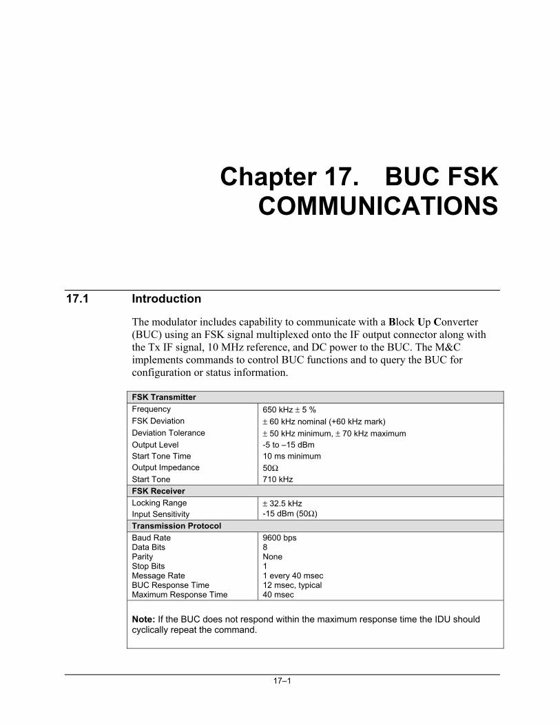
17–1
Chapter 17. BUC FSK COMMUNICATIONS
17.1 Introduction
The modulator includes capability to communicate with a Block Up Converter (BUC) using an FSK signal multiplexed onto the IF output connector along with the Tx IF signal, 10 MHz reference, and DC power to the BUC. The M&C implements commands to control BUC functions and to query the BUC for configuration or status information.
FSK Transmitter Frequency 650 kHz ± 5 % FSK Deviation ± 60 kHz nominal (+60 kHz mark) Deviation Tolerance ± 50 kHz minimum, ± 70 kHz maximum Output Level -5 to –15 dBm Start Tone Time 10 ms minimum Output Impedance 50Ω Start Tone 710 kHz FSK Receiver Locking Range Input Sensitivity
± 32.5 kHz -15 dBm (50Ω)
Transmission Protocol Baud Rate Data Bits Parity Stop Bits Message Rate BUC Response Time Maximum Response Time
9600 bps 8 None 1 1 every 40 msec 12 msec, typical 40 msec
Note: If the BUC does not respond within the maximum response time the IDU should cyclically repeat the command.
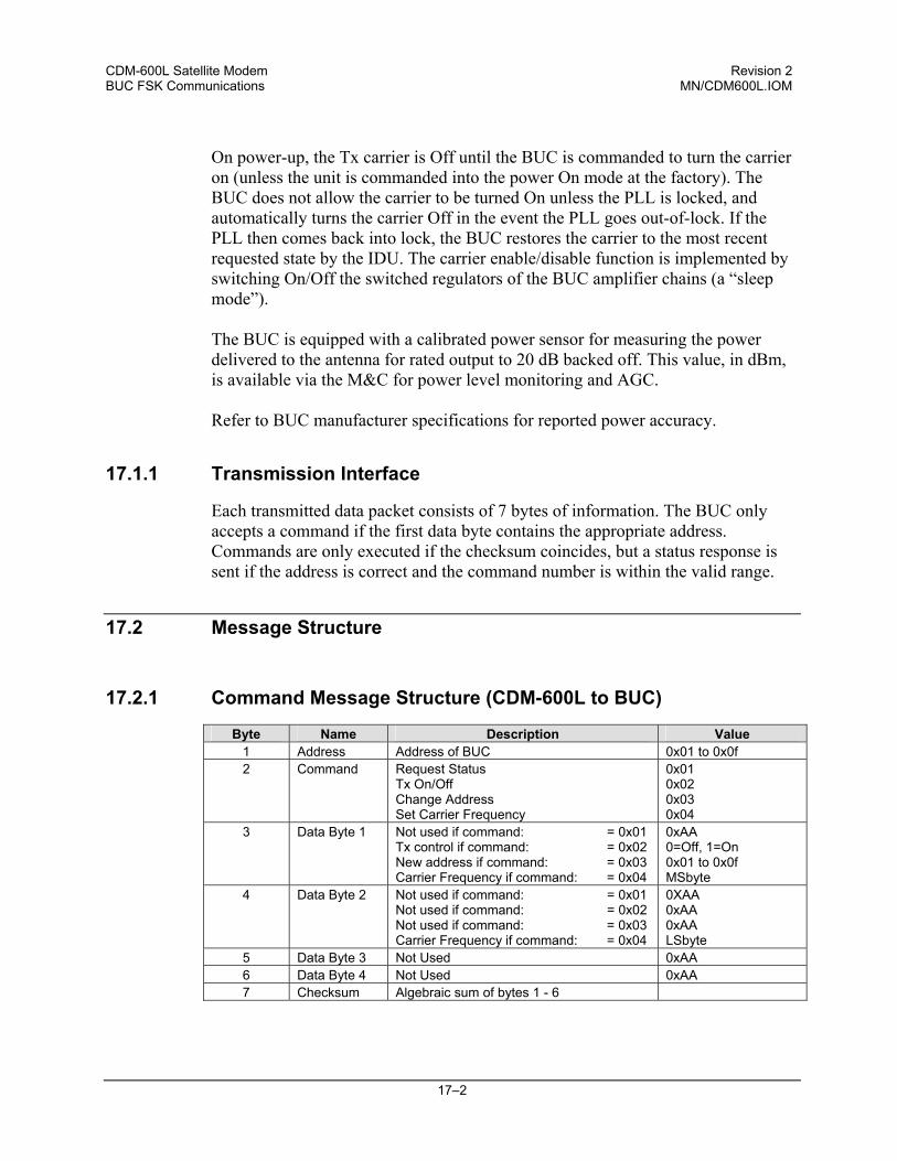
CDM-600L Satellite Modem Revision 2 BUC FSK Communications MN/CDM600L.IOM
17–2
On power-up, the Tx carrier is Off until the BUC is commanded to turn the carrier on (unless the unit is commanded into the power On mode at the factory). The BUC does not allow the carrier to be turned On unless the PLL is locked, and automatically turns the carrier Off in the event the PLL goes out-of-lock. If the PLL then comes back into lock, the BUC restores the carrier to the most recent requested state by the IDU. The carrier enable/disable function is implemented by switching On/Off the switched regulators of the BUC amplifier chains (a “sleep mode”).
The BUC is equipped with a calibrated power sensor for measuring the power delivered to the antenna for rated output to 20 dB backed off. This value, in dBm, is available via the M&C for power level monitoring and AGC. Refer to BUC manufacturer specifications for reported power accuracy.
17.1.1 Transmission Interface
Each transmitted data packet consists of 7 bytes of information. The BUC only accepts a command if the first data byte contains the appropriate address. Commands are only executed if the checksum coincides, but a status response is sent if the address is correct and the command number is within the valid range.
17.2 Message Structure
17.2.1 Command Message Structure (CDM-600L to BUC)
Byte Name Description Value 1 Address Address of BUC 0x01 to 0x0f 2 Command Request Status
Tx On/Off Change Address Set Carrier Frequency
0x01 0x02 0x03 0x04
3 Data Byte 1 Not used if command: = 0x01 Tx control if command: = 0x02 New address if command: = 0x03 Carrier Frequency if command: = 0x04
0xAA 0=Off, 1=On 0x01 to 0x0f MSbyte
4 Data Byte 2 Not used if command: = 0x01 Not used if command: = 0x02 Not used if command: = 0x03 Carrier Frequency if command: = 0x04
0XAA 0xAA 0xAA LSbyte
5 Data Byte 3 Not Used 0xAA 6 Data Byte 4 Not Used 0xAA 7 Checksum Algebraic sum of bytes 1 - 6
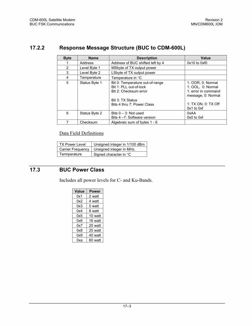
CDM-600L Satellite Modem Revision 2 BUC FSK Communications MN/CDM600L.IOM
17–3
17.2.2 Response Message Structure (BUC to CDM-600L)
Byte Name Description Value 1 Address Address of BUC shifted left by 4 0x10 to 0xf0 2 Level Byte 1 MSbyte of TX output power 3 Level Byte 2 LSbyte of TX output power 4 Temperature Temperature in °C 5 Status Byte 1 Bit 0: Temperature out-of-range
Bit 1: PLL out-of-lock Bit 2: Checksum error Bit 3: TX Status Bits 4 thru 7: Power Class
1: OOR, 0: Normal 1: OOL, 0: Normal 1: error in command message, 0: Normal 1: TX ON, 0: TX Off 0x1 to 0xf
6 Status Byte 2 Bits 0 – 3: Not used Bits 4 –7: Software version
0xAA 0x0 to 0xf
7 Checksum Algebraic sum of bytes 1 - 6
Data Field Definitions
TX Power Level Unsigned integer in 1/100 dBm Carrier Frequency Unsigned integer in MHz. Termperature Signed character in °C
17.3 BUC Power Class
Includes all power levels for C- and Ku-Bands.
Value Power 0x1 2 watt 0x2 4 watt 0x3 5 watt 0x4 8 watt 0x5 10 watt 0x6 16 watt 0x7 20 watt 0x8 25 watt 0x9 40 watt 0xa 60 watt
CDM-600L Satellite Modem Revision 2 BUC FSK Communications MN/CDM600L.IOM
17–4
17.4 BUC Output Power Leveling
The BUC’s capability to report the detected high power BUC output carrier level via the FSK link with the modem makes possible an automatic BUC output power leveling scheme. In this scheme, the CDM-600L M&C continually monitors the reported output power level from the BUC, and adjusts the modem transmit output carrier level to maintain the BUC output level at a target tracking value. This process is enabled when the FSK LEVELING is turned ON. When LEVELING changes from OFF to ON, the CDM-600L M&C reads the output power level reported by the BUC, and establishes that current output level as the target tracking level. Then, the M&C continues to monitor the BUC output level at 10-second intervals, and adjusts the modem output carrier level if needed to keep the BUC output level at the established target value. With LEVELING turned ON, the BUC output power level is held constant within the stability of the BUC output power detector. BUC output power leveling cannot be used in conjunction with AUPC since the two processes conflict directly with each other. Therefore, BUC output power leveling cannot be turned ON if AUPC is ON, and vice versa. Further, BUC output power leveling cannot be turned ON if the BUC output is turned off by FSK command, or if the BUC PLL is faulted. In these cases, there is no carrier output from the BUC so a valid tracking level cannot be established. Once leveling loop operation is established, however, the loop will “freeze” if :
1. A PLL fault in the BUC causes an automatic shut down of the output power amplifier
2. FSK communication fails 3. FSK is turned OFF 4. Modem IF output is turned OFF 5. FSK command turns OFF the BUC output.
Any of these events opens the feedback loop preventing valid level correction. Once the stimulus causing the loop to freeze is removed, the leveling loop will resume normal operation using the previously established target tracking level. A convenient way to verify that the leveling loop does indeed function is to first establish leveling loop operation, then turn off FSK and change the modem transmit output power level, and finally turn FSK back ON. Observe either the modem output power level in the CONFIGURATION: TX: POWER menu, or the monitored BUC output power level in the MONITOR: BUC menu. The levels will incrementally change at 10-second intervals to bring the BUC output back to the target tracking level.
CDM-600L Satellite Modem Revision 2 BUC FSK Communications MN/CDM600L.IOM
17–5
Turning both BUC FSK and output power leveling ON inhibits capability to manually change the modem transmit output carrier level since the leveling loop has control of the modem output. When leveling is turned ON, (ADJ) appears in the front panel display after the transmit power level in the CONFIGURATION-TX-POWER menu. Each time this menu is entered, the displayed transmit output power level is updated with the current value set by the leveling loop. BUC FSK related parameters, including leveling ON/OFF state and target tracking level, are stored in nonvolatile memory like all other modem parameters that determine the set up state. If FSK is turned ON, the modem M&C will set up FSK in the ON state if modem power is cycled OFF/ON. Likewise, if leveling is ON and operating, the modem will reestablish the leveling operation using the same target tracking level after a power cycle or after cycling the FSK state OFF and then back ON.

CDM-600L Satellite Modem Revision 2 BUC FSK Communications MN/CDM600L.IOM
17–6
NOTES:
18–1
Chapter 18. DST SETUP
This chapter describes the general setup of the modem in a Digital Satellite Terminal (DST) using the front panel keys. Detail operation of the modem is the same as specified in Chapters 1 through 16 of this manual.
18.1 Initial Operation
CAUTION
Careful setup is necessary to prevent damage to electronic components. Replacement of a component(s) may be the result. DC voltages for BUC or LNB power may be present at the modem transmit and receive IF connectors. Protect spectrum analyzers and other equipment sensitive to DC voltage with a DC block, such as Weinschel Model 7003, to prevent accidental damage.
18.1.1 Prior to Turning On Power
Note: Ensure DST system is installed properly and all connections all secure, except the L-Band TX and RX IF connectors which are initially disconnected. Observe the following steps:
Step No.
Selection / Programming
Menu Location
1. Make sure prime power to the Modem is removed. 2. Verify the IFL L-Band cables are not connected to the
modem.
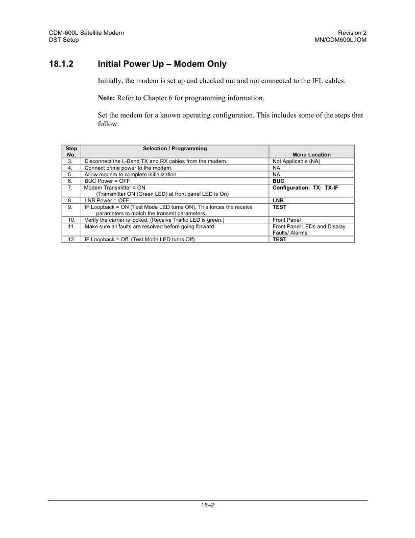
CDM-600L Satellite Modem Revision 2 DST Setup MN/CDM600L.IOM
18–2
18.1.2 Initial Power Up – Modem Only
Initially, the modem is set up and checked out and not connected to the IFL cables:
Note: Refer to Chapter 6 for programming information.
Set the modem for a known operating configuration. This includes some of the steps that follow.
Step No.
Selection / Programming Menu Location
3. Disconnect the L-Band TX and RX cables from the modem. Not Applicable (NA) 4. Connect prime power to the modem. NA 5. Allow modem to complete initialization. NA 6. BUC Power = OFF BUC 7. Modem Transmitter = ON
(Transmitter ON (Green LED) at front panel LED is On) Configuration: TX: TX-IF
8. LNB Power = OFF LNB 9. IF Loopback = ON (Test Mode LED turns ON). This forces the receive
parameters to match the transmit parameters. TEST
10. Verify the carrier is locked. (Receive Traffic LED is green.) Front Panel 11. Make sure all faults are resolved before going forward. Front Panel LEDs and Display
Faults/ Alarms 12. IF Loopback = Off (Test Mode LED turns Off). TEST
CDM-600L Satellite Modem Revision 2 DST Setup MN/CDM600L.IOM
18–3
18.2 LO, Mix and Spectrum (Inversion) Settings
The CDM-600L Satellite Modem permits programming of terminal (satellite) frequencies instead of the L-Band frequencies. This is useful because it allows direct entry of the assigned TX and RX frequencies. Three parameters are adjusted to setup the modem with the BUC/LNB. These parameters are:
♦ LO: Local Oscillator Frequency. ♦ Mix Sign: + or -, determines whether the L-Band carrier is added or
subtracted from the LO to translate to the satellite frequency. ♦ Mod Spectrum and Demod Spectrum (Inversion); needed to correct for any
inversion caused by the frequency translation.
The LO and MIX are entered into the modem to program the satellite frequency for the terminal. Consult the BUC manufacturer’s specifications for BUC LO specifications.
♦ MIX = “+” when LO < Satellite Operating Frequency ♦ MIX = “-” when LO > Satellite Operating Frequency
Whenever MIX = - the spectrum of the carrier is inverted. The CDM-600L easily corrects for this with the Invert ON/OFF selection located under the Configuration:TX:TX-IF and Configuration:RX:RX-IF menus. Match the Tx inversion to the MIX in the BUC and the Rx inversion to the MIX in the LNB using the following:
♦ Spectrum = Normal when MIX = + ♦ Spectrum = Invert when MIX = –
As a general rule it is best to radiate the spectrum toward the satellite in the Normal spectral sense. Then transmission links with any other corresponding sites are always consistent at the satellite interface. When doing RF loopback testing over the satellite or end-to-end the settings are correct with this setup. If there is a single inversion in the modem, however, for operation over the satellite, it will be necessary to temporarily match the spectral inversion of modulator and demodulator when performing IF loopback testing. Note: The modem will only allow programming of terminal frequencies that are within its valid L-Band frequency limits.
CDM-600L Satellite Modem Revision 2 DST Setup MN/CDM600L.IOM
18–4
18.3 Applying Power To The BUC
CAUTION
1. Care should be exercised in cable installation. Install the cables using the most direct route and secure with clamps and ties. Avoid all sharp bends. Replacement of the cables can be the result.
2. If the ODU voltage is not correct, DO NOT connect the TX-IF Cable to the modem or damage may result. Contact Comtech EF Data Customer Service department.
3. Ensure TX and RX L-Band cables are not connected. After the modem is checked out, then configure to operate with the ODU.
4. Initially, set LNB and BUC current wide enough to avoid false reports during installation. Readjust the limit at a later time.
5. For FSK operation with an FSK capable BUC see the Chapters 6 and 16. Complete steps 13 through 29 prior to continuing.
The conditions for the BUC to function are:
Proper TX L-Band power to the BUC from modem. Sufficient and correct DC power at the BUC 10 MHz reference supplied to the BUC
Note: Manufacturer recommends a 5-minute warm-up period at initial turn on for the BUC to ensure proper performance. This can be accomplished by performing steps 15 through 18, prior to initiating the power start-up.
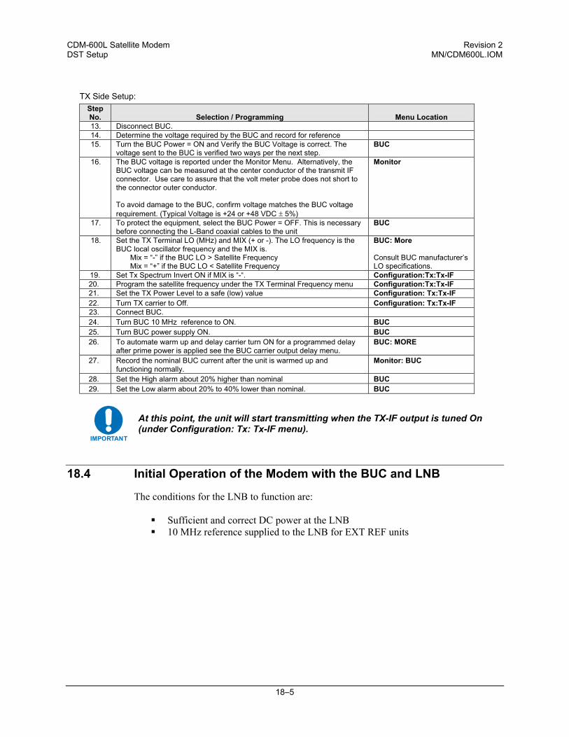
CDM-600L Satellite Modem Revision 2 DST Setup MN/CDM600L.IOM
18–5
TX Side Setup: Step No.
Selection / Programming
Menu Location
13. Disconnect BUC. 14. Determine the voltage required by the BUC and record for reference 15. Turn the BUC Power = ON and Verify the BUC Voltage is correct. The
voltage sent to the BUC is verified two ways per the next step. BUC
16. The BUC voltage is reported under the Monitor Menu. Alternatively, the BUC voltage can be measured at the center conductor of the transmit IF connector. Use care to assure that the volt meter probe does not short to the connector outer conductor. To avoid damage to the BUC, confirm voltage matches the BUC voltage requirement. (Typical Voltage is +24 or +48 VDC ± 5%)
Monitor
17. To protect the equipment, select the BUC Power = OFF. This is necessary before connecting the L-Band coaxial cables to the unit
BUC
18. Set the TX Terminal LO (MHz) and MIX (+ or -). The LO frequency is the BUC local oscillator frequency and the MIX is. Mix = “-” if the BUC LO > Satellite Frequency Mix = “+” if the BUC LO < Satellite Frequency
BUC: More Consult BUC manufacturer’s LO specifications.
19. Set Tx Spectrum Invert ON if MIX is “-“. Configuration:Tx:Tx-IF 20. Program the satellite frequency under the TX Terminal Frequency menu Configuration:Tx:Tx-IF 21. Set the TX Power Level to a safe (low) value Configuration: Tx:Tx-IF 22. Turn TX carrier to Off. Configuration: Tx:Tx-IF
23. Connect BUC. 24. Turn BUC 10 MHz reference to ON. BUC 25. Turn BUC power supply ON. BUC 26. To automate warm up and delay carrier turn ON for a programmed delay
after prime power is applied see the BUC carrier output delay menu. BUC: MORE
27. Record the nominal BUC current after the unit is warmed up and functioning normally.
Monitor: BUC
28. Set the High alarm about 20% higher than nominal BUC 29. Set the Low alarm about 20% to 40% lower than nominal. BUC
IMPORTANT
At this point, the unit will start transmitting when the TX-IF output is tuned On (under Configuration: Tx: Tx-IF menu).
18.4 Initial Operation of the Modem with the BUC and LNB
The conditions for the LNB to function are:
Sufficient and correct DC power at the LNB 10 MHz reference supplied to the LNB for EXT REF units
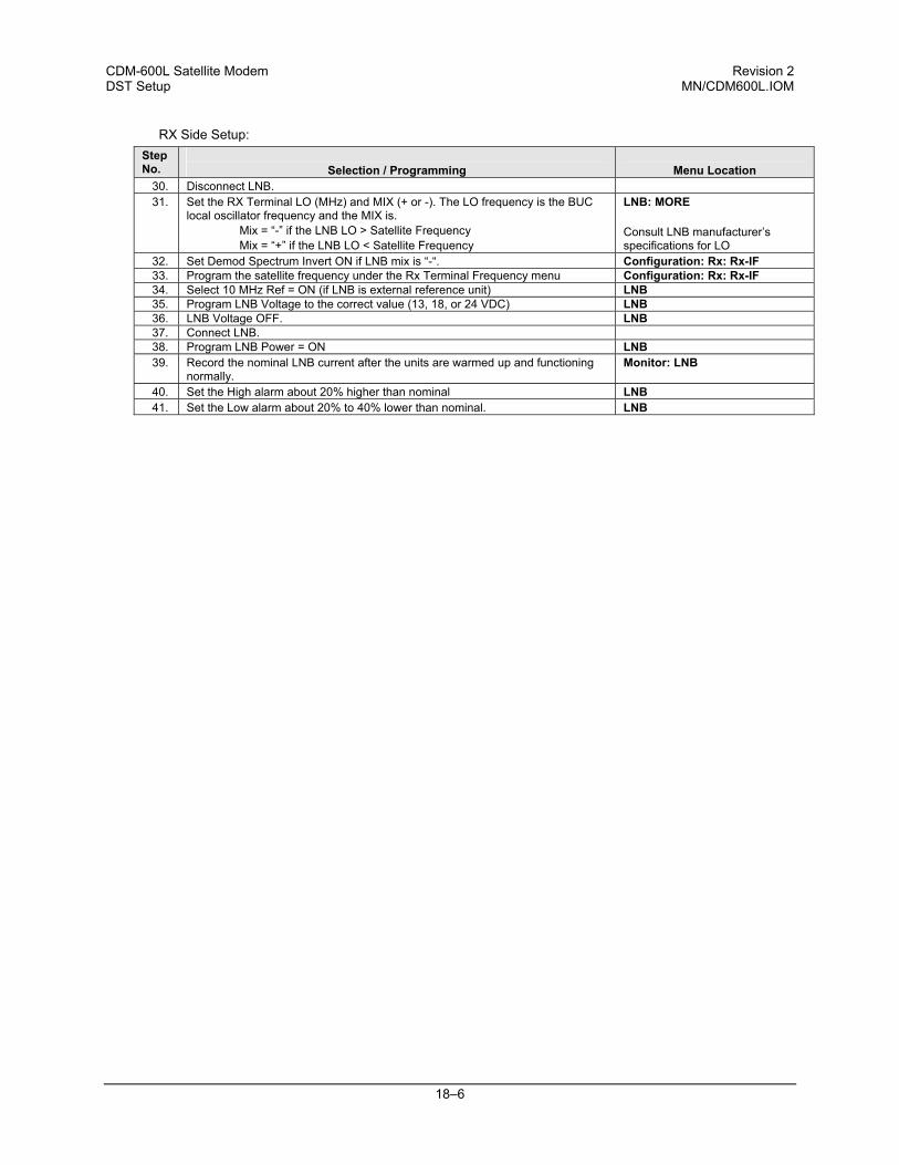
CDM-600L Satellite Modem Revision 2 DST Setup MN/CDM600L.IOM
18–6
RX Side Setup: Step No.
Selection / Programming
Menu Location
30. Disconnect LNB. 31. Set the RX Terminal LO (MHz) and MIX (+ or -). The LO frequency is the BUC
local oscillator frequency and the MIX is. Mix = “-” if the LNB LO > Satellite Frequency Mix = “+” if the LNB LO < Satellite Frequency
LNB: MORE Consult LNB manufacturer’s specifications for LO
32. Set Demod Spectrum Invert ON if LNB mix is “-“. Configuration: Rx: Rx-IF 33. Program the satellite frequency under the Rx Terminal Frequency menu Configuration: Rx: Rx-IF 34. Select 10 MHz Ref = ON (if LNB is external reference unit) LNB 35. Program LNB Voltage to the correct value (13, 18, or 24 VDC) LNB 36. LNB Voltage OFF. LNB 37. Connect LNB. 38. Program LNB Power = ON LNB 39. Record the nominal LNB current after the units are warmed up and functioning
normally. Monitor: LNB
40. Set the High alarm about 20% higher than nominal LNB 41. Set the Low alarm about 20% to 40% lower than nominal. LNB
A–1
Appendix A. CABLE DRAWINGS
The RS-530 standard pinout (provided on the CDM-600L) is becoming more popular in many applications. However, there are still many occasions when, especially for existing RS-422/449 and V.35 users, a conversion must be made. For these situations, the following two cable drawings show RS-530 to RS-422/449 DCE conversion, and RS-530 to V.35 DCE conversion. The third drawing shows a standard RS-232 cable for use with the Remote Control Port of the Modem. This should also be used for performing Flash Upgrading via an external PC.
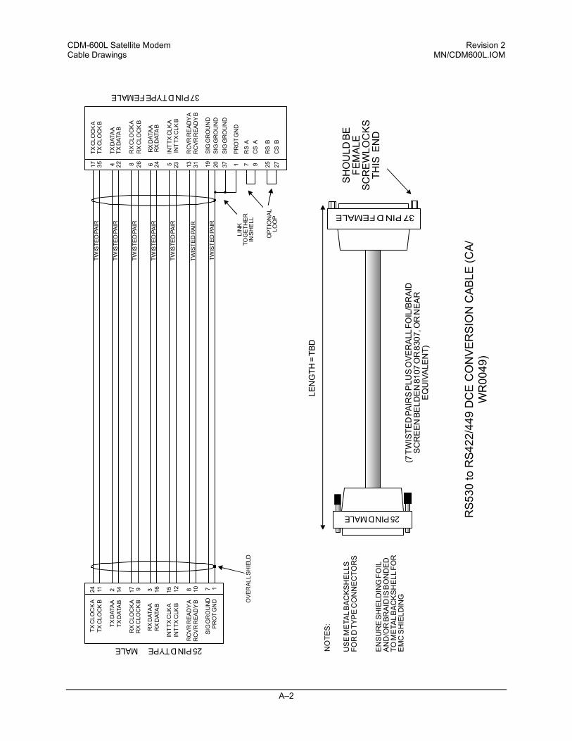
CDM-600L Satellite Modem Revision 2 Cable Drawings MN/CDM600L.IOM
A–2
TWIS
TED
PAIR
17TX
CLO
CK
A35
TXC
LOC
KB
4TX
DAT
AA
22TX
DAT
AB
8R
XC
LOC
KA
26R
XC
LOC
KB
13R
CVR
RE
ADY
A
24R
XD
ATA
B
5IN
TTX
CLK
A23
INT
TXC
LKB
20SI
GG
RO
UN
D19
SIG
GR
OU
ND
TXC
LOC
KA
24TX
CLO
CK
B11
TXD
ATA
A2
TXD
ATA
B14
RX
CLO
CK
A17
RX
CLO
CK
B9
RX
DAT
AA
3
RC
VRR
EAD
YB
10
INT
TXC
LKA
15IN
TTX
CLK
B12
PRO
TG
ND
1
1PR
OT
GN
D
SIG
GR
OU
ND
7
25PINDTYPEMALE
37PINDTYPEFEMALE
LEN
GTH
=TB
D
TWIS
TED
PAIR
TWIS
TED
PAIR
TWIS
TED
PAIR
TWIS
TED
PAIR
TWIS
TED
PAIR
TWIS
TED
PAIR
(7TW
ISTE
DPA
IRS
PLU
SO
VER
ALL
FOIL
/BR
AID
SC
RE
ENBE
LDE
N81
07O
R83
07,O
RN
EAR
EQ
UIV
ALE
NT)
25PINDMALE
SH
OU
LDBE
FEM
ALE
SCR
EW
LOC
KS
THIS
END
LIN
KTO
GET
HE
RIN
SH
ELL
OPT
ION
ALLO
OP
OVE
RAL
LSH
IELD
NO
TES
:
US
EM
ETA
LB
AC
KS
HE
LLS
FOR
DTY
PE
CO
NN
EC
TOR
S
EN
SU
RE
SH
IELD
ING
FOIL
AN
D/O
RB
RA
IDIS
BO
ND
ED
TOM
ETA
LBA
CK
SH
ELL
FOR
EM
CS
HIE
LDIN
G
RC
VRR
EAD
YA
8
RX
DAT
AB
16
31R
CVR
REA
DY
B
6R
XD
ATA
A
7R
SA
9C
SA
25R
SB
27C
SB
37SI
GG
RO
UN
D
RS5
30 to
RS4
22/4
49 D
CE
CO
NVE
RSI
ON
CAB
LE (C
A/W
R00
49)
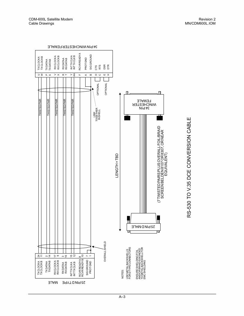
CDM-600L Satellite Modem Revision 2 Cable Drawings MN/CDM600L.IOM
A–3
U
TXC
LOC
KA
WTX
CLO
CK
B
PTX
DAT
AA
STX
DAT
AB
VR
XC
LOC
KA
XR
XC
LOC
KB
FR
CV
RR
EAD
YA
TR
XD
ATA
B
YIN
TTX
CLK
AA
AIN
TTX
CLK
B
BS
IGG
RO
UN
D
DC
TS
ED
SR
CR
TS
HD
TR
TXC
LOC
KA
24TX
CLO
CK
B11
TXD
ATA
A2
TXD
ATA
B14
RX
CLO
CK
A17
RX
CLO
CK
B9
RX
DAT
AA
3
RC
VRR
EAD
YB
10
INT
TXC
LKA
15IN
TTX
CLK
B12
PRO
TG
ND
1
AP
RO
TG
ND
SIG
GR
OU
ND
7
25PINDTYPEMALE
34PINWINCHESTERFEMALE
LEN
GTH
=TB
D
TWIS
TED
PAIR
TWIS
TED
PAIR
TWIS
TED
PAIR
TWIS
TED
PAIR
TWIS
TED
PAIR
(7TW
ISTE
DPA
IRS
PLU
SO
VER
ALL
FOIL
/BR
AID
SCR
EEN
BELD
EN
8107
OR
8307
,OR
NE
ARE
QU
IVA
LEN
T)
TOV.
35D
CE
CO
NVE
RSI
ON
CAB
LE
25PINDMALELI
NK
TOG
ETH
ERIN
SHEL
LO
PTI
ON
AL
OP
TIO
NA
LO
VER
ALLS
HIE
LD
NO
TES
:
USE
MET
ALBA
CKS
HEL
LSFO
RD
TYP
EC
ON
NE
CTO
RS
ENSU
RE
SHIE
LDIN
GFO
ILAN
D/O
RBR
AID
ISB
ON
DED
TOM
ETA
LBAC
KSH
ELLF
OR
EMC
SHIE
LDIN
G
RC
VRR
EAD
YA
8
RX
DAT
AB
16R
RX
DAT
AA
34PINWINCHESTER
FEMALE
R
S-5
30
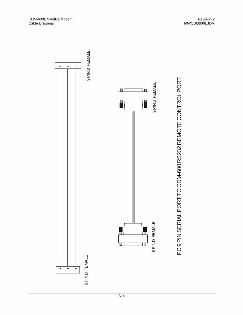
CDM-600L Satellite Modem Revision 2 Cable Drawings MN/CDM600L.IOM
A–4
B–1
Appendix B. Eb/No MEASUREMENT
Although the CDM-600L calculates and displays the value of receive Eb/No on the front panel of the unit, it is sometimes useful to measure the value using a spectrum analyzer, if one is available.
CDM-600L Satellite Modem Revision 2 Eb/No Measurement MN/CDM600L.IOM
B–2
The idea is to accurately measure the value of (Co+No)/No, (Carrier density + Noise density/Noise density). This is accomplished by tuning the center frequency of the Spectrum analyzer to the signal of interest, and measuring the difference between the peak spectral density of the signal (the flat part of the spectrum shown) and the noise density. To make this measurement: • Use a vertical scale of 1 or 2 dB/division.
• Set the Resolution Bandwidth of the Spectrum Analyzer to < 20 % of the symbol
rate.
• Use video filtering and/or video averaging to reduce the variance in the displayed trace to a low enough level that the difference can be measured to within 0.2dB.
• Place a marker on the flat part of the signal of interest, then use the MARKER
DELTA function to put a second marker on the noise to the side of the carrier. This value is (Co+No)/No, in dB.
• Use this value of (Co+No)/No in the table on the following page to determine the Eb/No. You will need to know the operating mode to read from the appropriate column.
• If the (Co+No)/No value measured does not correspond to an exact table entry,
interpolate using the two nearest values. Note that the accuracy of this method degrades significantly at low values of (Co+No)/No (approximately less than 6 dB).
Example: In the diagram above, the (Co+No)/No measured is 4.6 dB. If Rate 1/2 QPSK is being used, this would correspond to an Eb/No of approximately 2.6 dB. The exact relationship used to derive the table values is as follows:
Eb/No = 10 log10 (10 (Co+No/No )/10) -1) - 10 log10 (FEC Code Rate) - 10 log10 (bits/symbol)
and: • Eb/No and (Co+No)/No are expressed in dB • Bits/symbol = 1 for BPSK • Bits/symbol = 2 for QPSK • Bits/symbol = 3 for 8-PSK • Bits/symbol = 4 for 16-QAM • Code Rate for ‘uncoded’ = 1 • Pay close attention to the sign of the middle term
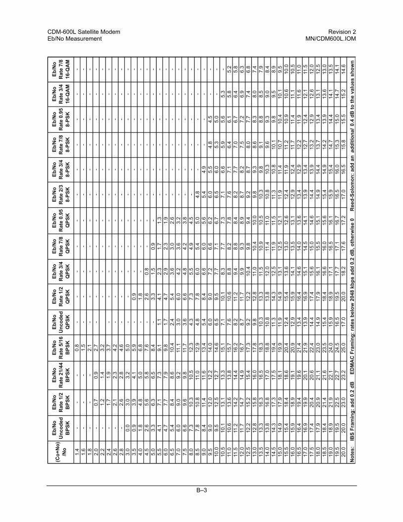
CDM-600L Satellite Modem Revision 2 Eb/No Measurement MN/CDM600L.IOM
B–3
(Co+
No)
/No
Eb/N
o
Unc
oded
B
PSK
Eb/N
o R
ate
1/2
BPS
K
Eb/N
o R
ate
21/4
4 B
PSK
Eb/N
o R
ate
5/16
B
PSK
Eb/N
o U
ncod
ed
QPS
K
Eb/N
o R
ate
1/2
QPS
K
Eb/N
o R
ate
3/4
QPS
K
Eb/N
o R
ate
7/8
QPS
K
Eb/N
o R
ate
0.95
Q
PSK
Eb/N
o R
ate
2/3
8-
PSK
Eb/N
o
Rat
e 3/
4
8-
PSK
Eb/N
o R
ate
7/8
8-
PSK
Eb/N
o R
ate
0.95
8-
PSK
Eb/N
o R
ate
3/4
16
-QA
M
Eb/N
o R
ate
7/8
16
-QA
M
1.4
--
-0.
8-
--
--
--
--
--
1.6
--
-1.
5-
--
--
--
--
--
1.8
--
-2.
1-
--
--
--
--
--
2.0
-0.
70.
92.
7-
--
--
--
--
--
2.2
-1.
21.
43.
2-
--
--
--
--
-2.
4-
1.7
1.9
3.7
--
--
--
--
--
-2.
6-
2.1
2.3
4.2
--
--
--
--
--
-2.
8-
2.6
2.8
4.6
--
--
--
--
--
-3.
00.
03.
03.
25.
0-
--
--
--
--
--
3.5
0.9
3.9
4.1
5.9
-0.
9-
--
--
--
--
4.0
1.8
4.8
5.0
6.8
-1.
8-
--
--
--
--
4.5
2.6
5.6
5.8
7.6
-2.
60.
8-
--
--
--
-5.
03.
36.
36.
58.
4-
3.3
1.5
0.9
--
--
--
-5.
54.
17.
17.
39.
11.
14.
12.
31.
71.
3-
--
--
-6.
04.
77.
77.
99.
81.
74.
72.
92.
31.
9-
--
--
-6.
55.
48.
48.
610
.42.
45.
43.
63.
02.
6-
--
--
-7.
06.
09.
09.
211
.13.
06.
04.
23.
63.
2-
--
--
-7.
56.
69.
69.
811
.73.
66.
64.
84.
23.
8-
--
--
-8.
07.
310
.310
.512
.34.
37.
35.
54.
94.
5-
--
--
-8.
57.
810
.811
.012
.94.
87.
86.
05.
45.
04.
8-
--
--
9.0
8.4
11.4
11.6
13.4
5.4
8.4
6.6
6.0
5.6
5.4
4.9
--
--
9.5
9.0
12.0
12.2
14.0
6.0
9.0
7.2
6.6
6.2
6.0
5.5
4.8
4.5
--
10.0
9.5
12.5
12.7
14.6
6.5
9.5
7.7
7.1
6.7
6.5
6.0
5.3
5.0
--
10.5
10.1
13.1
13.3
15.1
7.1
10.1
8.3
7.7
7.3
7.1
6.6
5.9
5.6
5.3
-11
.010
.613
.613
.815
.77.
610
.68.
88.
27.
87.
67.
16.
46.
15.
85.
211
.511
.214
.214
.416
.28.
211
.29.
48.
88.
48.
27.
77.
06.
76.
45.
812
.011
.714
.714
.916
.78.
711
.79.
99.
38.
98.
78.
27.
57.
26.
96.
312
.512
.215
.215
.417
.39.
212
.210
.49.
89.
49.
28.
78.
07.
77.
46.
813
.012
.815
.816
.017
.89.
812
.811
.010
.410
.09.
89.
38.
68.
38.
07.
413
.513
.316
.316
.518
.310
.313
.311
.510
.910
.510
.39.
89.
18.
88.
57.
914
.013
.816
.817
.018
.810
.813
.812
.011
.411
.010
.810
.39.
69.
39.
08.
414
.514
.317
.317
.519
.411
.314
.312
.511
.911
.511
.310
.810
.19.
89.
58.
915
.014
.917
.918
.119
.911
.914
.913
.112
.512
.111
.911
.410
.710
.410
.19.
515
.515
.418
.418
.620
.412
.415
.413
.613
.012
.612
.411
.911
.210
.910
.610
.016
.015
.918
.919
.120
.912
.915
.914
.113
.513
.112
.912
.411
.711
.411
.110
.516
.516
.419
.419
.621
.413
.416
.414
.614
.013
.613
.412
.912
.211
.911
.611
.017
.016
.919
.920
.121
.913
.916
.915
.114
.514
.113
.913
.412
.712
.412
.111
.517
.517
.420
.420
.622
.414
.417
.415
.615
.014
.614
.413
.913
.212
.912
.612
.018
.017
.920
.921
.123
.014
.917
.916
.115
.515
.114
.914
.413
.713
.413
.112
.518
.518
.421
.421
.623
.515
.418
.416
.616
.015
.615
.414
.914
.213
.913
.613
.019
.018
.921
.922
.124
.015
.918
.917
.116
.516
.115
.915
.414
.714
.414
.113
.519
.519
.522
.522
.724
.516
.519
.517
.717
.116
.716
.516
.015
.315
.014
.714
.120
.020
.023
.023
.225
.017
.020
.018
.217
.617
.217
.016
.515
.815
.515
.214
.6
Not
es:
IB
S Fr
amin
g: a
dd 0
.2 d
B
ED
MA
C F
ram
ing:
rate
s be
low
204
8 kb
ps a
dd 0
.2 d
B, o
ther
wis
e 0
R
eed-
Solo
mon
: add
an additional
0.4
dB to
the
valu
es s
how
n

CDM-600L Satellite Modem Revision 2 Eb/No Measurement MN/CDM600L.IOM
B–4
NOTES:
C–1
Appendix C. FAST ACTIVATION PROCEDURE
C.1 Introduction
FAST is an enhancement feature available in Comtech EF Data products, enabling on-location upgrade of the operating feature set—in the rack—without removing a modem from the setup. This accelerated upgrade can be accomplished only because of FAST’s extensive use of programmable devices incorporating Comtech EF Data-proprietary signal processing techniques. These techniques allow the use of a unique access code to enable configuration of the available hardware. The access code can be purchased at any time from Comtech EF Data. Once obtained, the access code is loaded into the unit through the front panel keyboard.
C.2 Activation Procedure
C.2.1 Serial Number
Obtain the Modem serial number as follows: a. From the main menu, select FAST, then [ENTER]. b. The Modem motherboard Serial Number is displayed on the bottom line, to
the left. c. Record serial number:
CDM-600L Satellite Modem Revision 2 FAST Activation Procedure MN/CDM600L.IOM
C–2
C.2.2 View currently installed features
To view the currently installed features, proceed as follows:
a. From the main menu, select FAST, then [ENTER]. b. From the FAST OPTIONS menu, select VIEW, then [ENTER]. c. Scroll through the Modem Options and note which are ‘Installed’ or ‘Not
Installed’. Any that are ‘Not Installed’ may be purchased as a FAST upgrade.
Contact a Comtech EF Data sales representative to order features. You will be asked to provide the Modem Serial Number. Comtech EF Data Customer Support personnel will verify the order and provide an invoice and instructions, including a 20-character configuration code.
C.2.3 Enter Access Codes
Enter the access codes as follows:
a. Press [CLEAR] to return to the FAST OPTIONS menu. b. Select SET. c. Press [ENTER]. d. Use [←][→] and [↑][↓] arrow keys to enter the 20 character config code. e. Press [ENTER].
If everything has been entered correctly, the display will show “CONFIGURED CORRECTLY” and the modem resets to its default configuration.
i-1
Index
A
Activation Procedure, 1-6 Address, 6-24, 6-32, 16-2, 16-3, 16-20,
16-34 Alarm, 6-2, 6-17, 6-26, 6-34, 9-1, 9-3, 9-4,
12-3, 16-12, 16-17, 16-18, 16-22, 16-28, 16-34
AUPC, 1-2, 1-4, 6-6, 6-9, 6-10, 6-36, 6-37, 11-3, 12-1, 12-2, 12-3, 12-4, 15-1, 15-9, 16-10, 16-22, 16-23, 16-28, 16-31, 16-34
Automatic Uplink Power Control, 1-2, 12-1, 15-3
B
Basic Protocol, 16-2 Buffer Disabled, 10-3 Buffer Enabled, 10-3
C
Compatibility, 1-7 Compensation Rate, 12-3 CONFIG, 6-6, 6-7, 6-8, 6-9, 6-10, 6-11,
6-12, 6-13, 6-14, 6-15, 6-16, 6-17, 6-20, 6-21, 6-22, 6-23, 6-24, 6-25, 6-26, 6-27, 6-36, 12-2, C-1, C-2
Configuration, 2-4, 6-5, 16-23, 16-34 Connect External Cables, 2-4
D
D&I Framing, 9-3 D&I Primary Data Interfaces, 9-3 D&I++, 1-2, 6-19, 10-6, 10-7, 11-4, 15-2,
15-11, 16-13, 16-27
Data Interfaces, 1-3 Demod Unlock, 12-3 Demodulator, 15-9, 16-28 Dimensional Envelope, 4-6 Drop & Insert ++, 11-4 Drop and Insert, 1-1, 1-4, 6-20, 9-1, 9-2,
10-1, 10-3, 10-6, 10-8, 15-1, 15-9, 16-27, 16-33
E
EIA-232, 1-3, 4-4, 4-5, 6-24, 9-1, 9-2, 9-3, 10-1, 14-1, 15-9, 15-11, 16-1, 16-2, 16-3, A-1
EIA-485, 4-5, 6-24, 15-11, 16-1, 16-2, 16-3 End Of Packet, 16-5 External Clock, 6-6, 15-9 External Refence, 6-6 External Reference, 10-2, 10-3, 15-3, 15-9,
16-11, 16-17
F
FAST, 1-4, 1-5, 1-6, 4-4, 6-5, 6-7, 6-8, 6-10, 6-12, 6-14, 6-16, 6-20, 6-46, 15-9, C-1, C-2
FAST Accessible Options, 1-5 FAST Activation Procedure, C-1 FAST Options and Hardware Options, 1-4 FAST System Theory, 1-5 Flash Upgrading, A-1 Frame formats, 10-6 Front Panel, 4-1, 4-2, 6-1, 6-2 Front Panel Operation, 4-2
H
Hardware Options, 1-6
CDM-600L Satellite Modem Revision 2 Index MN/CDM600L.IOM
i-2
I
IBS Clock/data recovery and De-jitter, 9-2 IBS Engineering Service Channel, 9-2 IBS Framing, 9-2 IBS Scrambling, 9-2 IDR Engineering Service Channel, 9-5 IDR Primary Data Interfaces, 9-5 Implementation, 1-6 Installation, 1-4, 2-3 Installation of the Mounting Bracket, 2-2 Instruction Code, 16-4, 16-7, 16-13, 16-20,
16-27, 16-33, 16-36, 16-39 Instruction Code Qualifier, 16-4 Internal Clock, 10-1, 10-2
L
Loop-Timed, 10-2, 16-11
M
M&C Connection, 11-2 Main Menu, 6-5 Major Assemblies, 1-3 Max Range, 12-2 Message Arguments, 16-5 Modulator, 6-28, 15-4 MONITOR, 6-5, 6-34, 6-35, 6-37, 12-4 Monitoring, 12-4 Mounting, 2-2, 2-3
O
Opening Screen, 6-5 Operating modes, 15-1
P
Packet Structure, 16-3
R
Rear Panel, 4-2 Receive Clocking, 10-3 Remote Control, 4-2, 4-5, 6-6, 15-9, A-1 Rx Buffer Clock = Insert (D&I only), 10-9
S
Select Internal IF Loop, 2-4 Sequential, 1-1, 1-4, 3-1, 6-10, 6-14, 15-2,
15-5, 16-14 Setting AUPC Parameters, 12-2 Setup Summary, 11-3 Software - Flash Upgrading, 1-3 Standard Features, 1-2 Start Of Packet, 16-3 STORE/LOAD, 6-5, 6-39 Supporting Hardware and Software, 1-6
T
Target Eb/No, 12-2, 15-9 TEST, 2-4, 6-5, 6-28 Theory Of Operation, 11-1 Time Slot Selection, 10-7 Transmit Clocking, 10-1
U
Unpacking, 2-1 UTILITIES, 6-40, 6-41
V
Verification, 1-3 Viterbi, 1-1, 1-4, 3-1, 6-2, 6-10, 6-14, 6-28,
15-2, 15-5, 16-14
X
X.21 Notes, 10-3
Copyright © Comtech EF Data Corporation, 2003,2004,2005. All rights reserved. Printed in the USA. Comtech EF Data Corporation, 2114 W. 7th Street, Tempe, Arizona 85281 USA, (480) 333-2200, FAX: (480) 333-2161.
CDM-600L Open Network Satellite Modem Manual Addendum A Subject: Update for new Drop and Insert capability Part Number: MN/CDM600L.AA2 Revision 2 Addendum A October 13, 2005 Special Instructions: This document contains changes and new information for the CDM-600L Open Network Satellite Modem manual, part number MN/CDM600L.IOM Rev. 2 dated March 9, 2005.
Comtech EF Data is an ISO 9001 Registered Company
New Features/Changes ( Version 1.4.0+)
• Changes to Drop and Insert
Since Version 2 of the CDM-600L Manual was published, there has been engineering development to modify the E1 Drop and Insert feature to add high-rate ESC (Engineering Service Channel) and AUPC (Automatic Uplink Power Control).
• New remote control commands Two new commands have been added to query the Tx and Rx symbol rates. These are TSR? and RSR? respectively (query-only). This information was already displayed on the front panel, but had not been available via the remote port.
A front panel lockout feature has been added. Already, when in remote mode, user access of the front panel of the modem allows viewing of the configuration parameters, but does not allow changes to the configuration parameters. To make changes via the front panel, the user must first configure the modem for Local control via the Remote menu. This front panel lockout (FPL) feature, when activated, prevents or locks-out that ability to configure the modem into local mode from the front panel.
Refer to the remote control command table, following, for more detail.
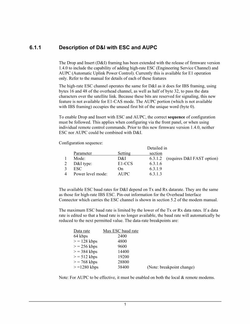
1
6.1.1 Description of D&I with ESC and AUPC
The Drop and Insert (D&I) framing has been extended with the release of firmware version 1.4.0 to include the capability of adding high-rate ESC (Engineering Service Channel) and AUPC (Automatic Uplink Power Control). Currently this is available for E1 operation only. Refer to the manual for details of each of these features
The high-rate ESC channel operates the same for D&I as it does for IBS framing, using bytes 16 and 48 of the overhead channel, as well as half of byte 32, to pass the data characters over the satellite link. Because these bits are reserved for signaling, this new feature is not available for E1-CAS mode. The AUPC portion (which is not available with IBS framing) occupies the unused first bit of the unique word (byte 0). To enable Drop and Insert with ESC and AUPC, the correct sequence of configuration must be followed. This applies when configuring via the front panel, or when using individual remote control commands. Prior to this new firmware version 1.4.0, neither ESC nor AUPC could be combined with D&I. Configuration sequence: Detailed in Parameter Setting section 1 Mode: D&I 6.3.1.2 (requires D&I FAST option) 2 D&I type: E1-CCS 6.3.1.6 3 ESC On 6.3.1.9 4 Power level mode: AUPC 6.3.1.3 The available ESC baud rates for D&I depend on Tx and Rx datarate. They are the same as those for high-rate IBS ESC. Pin-out information for the Overhead Interface Connector which carries the ESC channel is shown in section 5.2 of the modem manual. The maximum ESC baud rate is limited by the lower of the Tx or Rx data rates. If a data rate is edited so that a baud rate is no longer available, the baud rate will automatically be reduced to the next permitted value. The data-rate breakpoints are:
Data rate Max ESC baud rate 64 kbps 2400 > = 128 kbps 4800 > = 256 kbps 9600 > = 384 kbps 14400 > = 512 kbps 19200 > = 768 kbps 28800 > =1280 kbps 38400 (Note: breakpoint change)
Note: For AUPC to be effective, it must be enabled on both the local & remote modems.
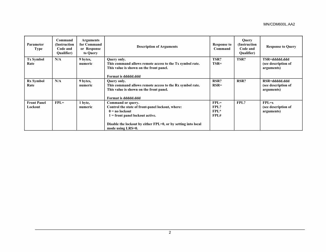
MN/CDM600L.AA2
2
Parameter Type
Command (Instruction
Code and Qualifier)
Arguments for Command or Response
to Query
Description of Arguments Response to Command
Query (Instruction
Code and Qualifier)
Response to Query
Tx Symbol Rate
N/A 9 bytes, numeric
Query only. This command allows remote access to the Tx symbol rate. This value is shown on the front panel. Format is ddddd.ddd
TSR? TSR=
TSR? TSR=ddddd.ddd (see description of arguments)
Rx Symbol Rate
N/A 9 bytes, numeric
Query only. This command allows remote access to the Rx symbol rate. This value is shown on the front panel. Format is ddddd.ddd
RSR? RSR=
RSR? RSR=ddddd.ddd (see description of arguments)
Front Panel Lockout
FPL= 1 byte, numeric
Command or query. Control the state of front-panel lockout, where: 0 = no lockout 1 = front panel lockout active. Disable the lockout by either FPL=0, or by setting into local mode using LRS=0.
FPL= FPL? FPL* FPL#
FPL? FPL=x (see description of arguments)
CDM-600L Open Network Satellite Modem Manual Addendum A Subject: Field Installation instructions, Front Panel Operations and Remote Commands for External 20 dB Step Attenuator Kit Part Number: KT/11202-1 Addendum A January 10, 2005
Comtech EF Data is an ISO 9001 Registered Company Copyright © Comtech EF Data Corporation, 2005. All rights reserved. Printed in the USA. Comtech EF Data Corporation, 2114 W. 7th Street, Tempe, Arizona 85281 USA, (480) 333-2200, FAX: (480) 333-2161.

CDM-600L Field Installation Instructions KT/11202-1 External 20 dB Step Attenuator Kit
2
This page is intentionally left blank.
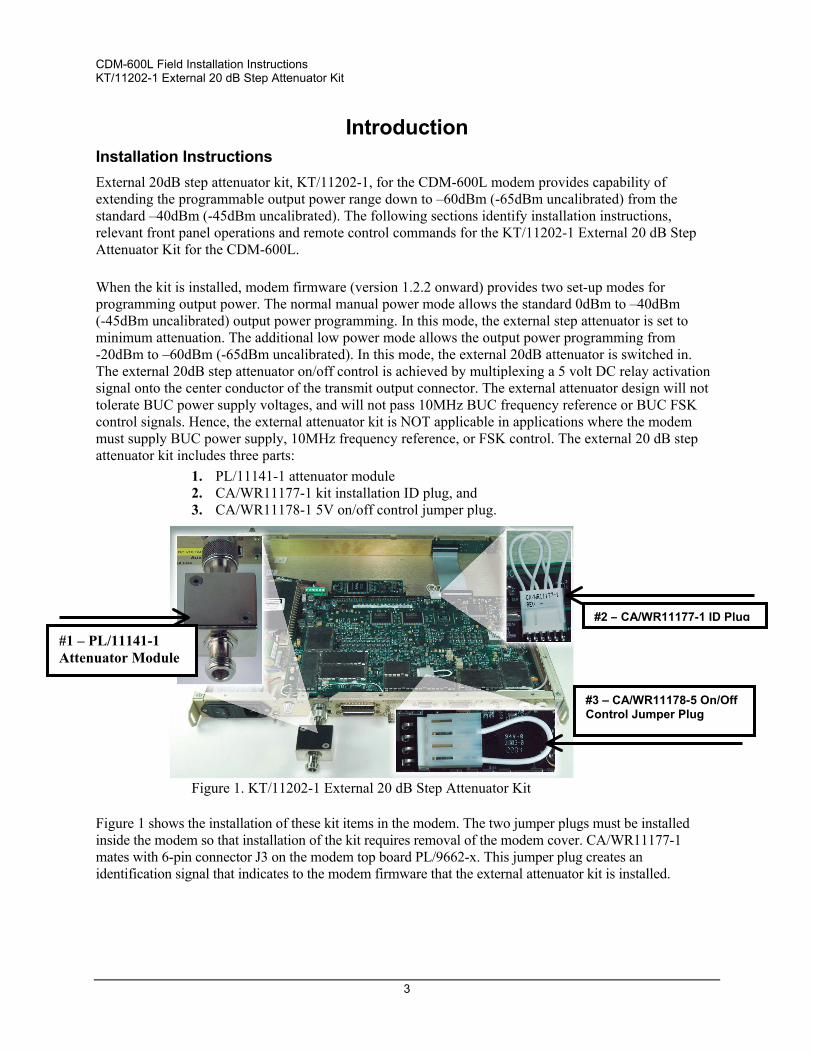
CDM-600L Field Installation Instructions KT/11202-1 External 20 dB Step Attenuator Kit
3
Introduction Installation Instructions External 20dB step attenuator kit, KT/11202-1, for the CDM-600L modem provides capability of extending the programmable output power range down to –60dBm (-65dBm uncalibrated) from the standard –40dBm (-45dBm uncalibrated). The following sections identify installation instructions, relevant front panel operations and remote control commands for the KT/11202-1 External 20 dB Step Attenuator Kit for the CDM-600L. When the kit is installed, modem firmware (version 1.2.2 onward) provides two set-up modes for programming output power. The normal manual power mode allows the standard 0dBm to –40dBm (-45dBm uncalibrated) output power programming. In this mode, the external step attenuator is set to minimum attenuation. The additional low power mode allows the output power programming from -20dBm to –60dBm (-65dBm uncalibrated). In this mode, the external 20dB attenuator is switched in. The external 20dB step attenuator on/off control is achieved by multiplexing a 5 volt DC relay activation signal onto the center conductor of the transmit output connector. The external attenuator design will not tolerate BUC power supply voltages, and will not pass 10MHz BUC frequency reference or BUC FSK control signals. Hence, the external attenuator kit is NOT applicable in applications where the modem must supply BUC power supply, 10MHz frequency reference, or FSK control. The external 20 dB step attenuator kit includes three parts:
1. PL/11141-1 attenuator module 2. CA/WR11177-1 kit installation ID plug, and 3. CA/WR11178-1 5V on/off control jumper plug.
Figure 1. KT/11202-1 External 20 dB Step Attenuator Kit Figure 1 shows the installation of these kit items in the modem. The two jumper plugs must be installed inside the modem so that installation of the kit requires removal of the modem cover. CA/WR11177-1 mates with 6-pin connector J3 on the modem top board PL/9662-x. This jumper plug creates an identification signal that indicates to the modem firmware that the external attenuator kit is installed.
#2 – CA/WR11177-1 ID Plug
#3 – CA/WR11178-5 On/Off Control Jumper Plug
#1 – PL/11141-1 Attenuator Module
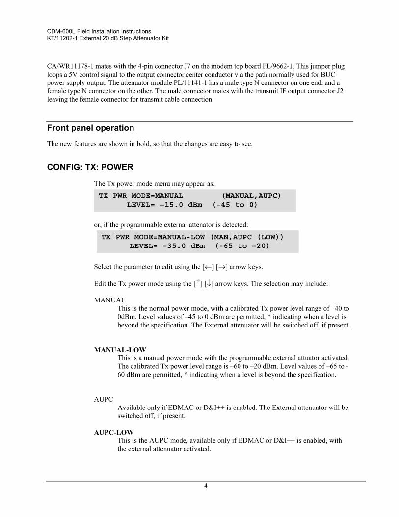
CDM-600L Field Installation Instructions KT/11202-1 External 20 dB Step Attenuator Kit
4
CA/WR11178-1 mates with the 4-pin connector J7 on the modem top board PL/9662-1. This jumper plug loops a 5V control signal to the output connector center conductor via the path normally used for BUC power supply output. The attenuator module PL/11141-1 has a male type N connector on one end, and a female type N connector on the other. The male connector mates with the transmit IF output connector J2 leaving the female connector for transmit cable connection.
Front panel operation
The new features are shown in bold, so that the changes are easy to see.
CONFIG: TX: POWER
The Tx power mode menu may appear as:
or, if the programmable external attenator is detected:
Select the parameter to edit using the [←] [→] arrow keys. Edit the Tx power mode using the [↑] [↓] arrow keys. The selection may include: MANUAL
This is the normal power mode, with a calibrated Tx power level range of –40 to 0dBm. Level values of –45 to 0 dBm are permitted, * indicating when a level is beyond the specification. The External attenuator will be switched off, if present.
MANUAL-LOW
This is a manual power mode with the programmable external attuator activated. The calibrated Tx power level range is –60 to –20 dBm. Level values of –65 to -60 dBm are permitted, * indicating when a level is beyond the specification.
AUPC
Available only if EDMAC or D&I++ is enabled. The External attenuator will be switched off, if present.
AUPC-LOW This is the AUPC mode, available only if EDMAC or D&I++ is enabled, with the external attenuator activated.
TX PWR MODE=MANUAL (MANUAL,AUPC) LEVEL= –15.0 dBm (-45 to 0)
TX PWR MODE=MANUAL-LOW (MAN,AUPC (LOW)) LEVEL= –35.0 dBm (-65 to –20)
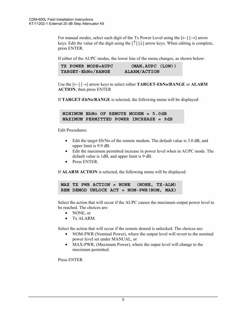
CDM-600L Field Installation Instructions KT/11202-1 External 20 dB Step Attenuator Kit
5
For manual modes, select each digit of the Tx Power Level using the [←] [→] arrow keys. Edit the value of the digit using the [↑] [↓] arrow keys. When editing is complete, press ENTER. If either of the AUPC modes, the lower line of the menu changes, as shown below:
Use the [←] [→] arrow keys to select either TARGET-EbNo/RANGE or ALARM ACTION, then press ENTER If TARGET-EbNo/RANGE is selected, the following menu will be displayed:
Edit Procedures:
• Edit the target Eb/No of the remote modem. The default value is 3.0 dB, and upper limit is 9.9 dB.
• Edit the maximum permitted increase in power level when in AUPC mode. The default value is 1dB, and upper limit is 9 dB.
• Press ENTER. If ALARM ACTION is selected, the following menu will be displayed:
Select the action that will occur if the AUPC causes the maximum output power level to be reached. The choices are:
• NONE, or • Tx ALARM.
Select the action that will occur if the remote demod is unlocked. The choices are:
• NOM-PWR (Nominal Power), where the output level will revert to the nominal power level set under MANUAL, or
• MAX-PWR, (Maximum Power), where the ouput level will change to the maximum permitted.
Press ENTER
TX POWER MODE=AUPC (MAN,AUPC (LOW)) TARGET-EbNo/RANGE ALARM/ACTION
MINIMUM EbNo OF REMOTE MODEM = 5.0dBMAXIMUM PERMITTED POWER INCREASE = 9dB
MAX TX PWR ACTION = NONE (NONE, TX-ALM) REM DEMOD UNLOCK ACT = NOM-PWR(NOM, MAX)
CDM-600L Field Installation Instructions KT/11202-1 External 20 dB Step Attenuator Kit
6
REMOTE CONTROL
New/Modified Remote Control Commands
The changes to the Remote Control commands are indicated in bold on the following pages.
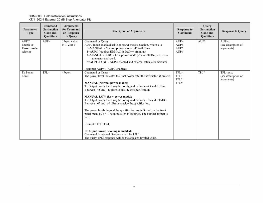
CDM-600L Field Installation Instructions KT/11202-1 External 20 dB Step Attenuator Kit
7
Parameter Type
Command (Instruction
Code and Qualifier)
Arguments for Command or Response
to Query
Description of Arguments Response to Command
Query (Instruction
Code and Qualifier)
Response to Query
AUPC Enable or Power mode selector
AUP= 1 byte, value 0, 1, 2 or 3
Command or Query. AUPC mode enable/disable or power mode selection, where x is: 0=MANUAL - Normal power mode (-45 to 0dBm) 1=AUPC (requires EDMAC or D&I++ framing) 2=MANUAL-LOW - Low power mode (-65 to -20dBm) - external
attenuator activated. 3=AUPC-LOW - AUPC enabled and external attenuator activated. Example: AUP=1 (AUPC enabled)
AUP= AUP? AUP* AUP#
AUP? AUP=x (see description of arguments)
Tx Power Level
TPL= 4 bytes Command or Query. The power level indicates the final power after the attenuator, if present. MANUAL (Normal power mode): Tx Output power level may be configured between –45 and 0 dBm. Between –45 and –40 dBm is outside the specification. MANUAL-LOW (Low power mode): Tx Output power level may be configured between –65 and -20 dBm. Between –65 and -60 dBm is outside the specification. The power levels beyond the specification are indicated on the front panel menu by a *. The minus sign is assumed. The number format is xx.x Example: TPL=13.4 If Output Power Leveling is enabled: Command is rejected. Response will be TPL*. The query TPL? response will be the adjusted leveled value.
TPL= TPL? TPL* TPL#
TPL? TPL=xx.x (see description of arguments)
CDM-600L Field Installation Instructions KT/11202-1 External 20 dB Step Attenuator Kit
8
Parameter Type
Command (Instruction
Code and Qualifier)
Arguments for Command or Response
to Query
Description of Arguments Response to Command
Query (Instruction
Code and Qualifier)
Response to Query
Equipment ID N/A 10 bytes Query only. Unit returns the equipment identification and installed options information, in the form abbbcdefgh; where: a=Turbo codec 0=None, 1=Lo-Rate Turbo, 2=Hi-Rate Turbo. bbb=defines the modem model number: 600 is the CDM-600 601 is the CDM-600L (this case) 602 is the CLM-9600L c=Data Rate Option: 0=Base (to 5 Mbps), 1=to 10 Mbps, 2=to 20 Mbps. d=Higher-order modulation option: 0=None, 1=8-PSK, 2=16-QAM, 3=8-PSK and 16-QAM. e=Framing option: 0=None, 1=IBS, 2=IDR, 3=IBS and IDR, 4=IBS with high-rate
ESC, 5=IBS with high-rate ESC and IDR.f=Drop and Insert/Audio mode 0=None, 1=D&I, 2=Audio, 3=D&I and Audio. (Note: D&I FAST option provides access to both Open Network
D&I and Closed Network D&I++) g=Special Options: 0=None, 1=Opt1, 2=Opt2, 3=Opt 1 and 2. h=External 20dB Attenuator: 0=None 1=Attenuator attached Example: EID=2601213301 indicates CDM-600L, Turbo 2 codec installed, 8-PSK/IDR/IBS, D&I, Audio, data rate to 20 Mbps, external attenuator installed.
N/A EID? EID=abbbcdefgh (see description of arguments) 601 indicates the CDM-600L
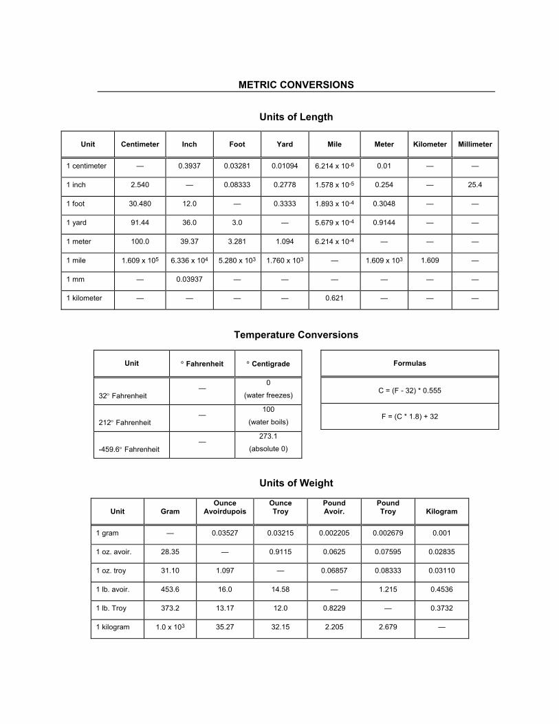
METRIC CONVERSIONS
Units of Length
Unit
Centimeter
Inch
Foot
Yard
Mile
Meter
Kilometer
Millimeter
1 centimeter — 0.3937 0.03281 0.01094 6.214 x 10⁻⁶ 0.01 — —
1 inch 2.540 — 0.08333 0.2778 1.578 x 10⁻⁵ 0.254 — 25.4
1 foot 30.480 12.0 — 0.3333 1.893 x 10⁻⁴ 0.3048 — —
1 yard 91.44 36.0 3.0 — 5.679 x 10⁻⁴ 0.9144 — —
1 meter 100.0 39.37 3.281 1.094 6.214 x 10⁻⁴ — — —
1 mile 1.609 x 10⁵ 6.336 x 10⁴ 5.280 x 10³ 1.760 x 10³ — 1.609 x 10³ 1.609 —
1 mm — 0.03937 — — — — — —
1 kilometer — — — — 0.621 — — —
Temperature Conversions
Units of Weight
Unit
Gram
Ounce Avoirdupois
Ounce Troy
Pound Avoir.
Pound Troy
Kilogram
1 gram — 0.03527 0.03215 0.002205 0.002679 0.001
1 oz. avoir. 28.35 — 0.9115 0.0625 0.07595 0.02835
1 oz. troy 31.10 1.097 — 0.06857 0.08333 0.03110
1 lb. avoir. 453.6 16.0 14.58 — 1.215 0.4536
1 lb. Troy 373.2 13.17 12.0 0.8229 — 0.3732
1 kilogram 1.0 x 10³ 35.27 32.15 2.205 2.679 —
Unit
° Fahrenheit
° Centigrade
32° Fahrenheit —
0
(water freezes)
212° Fahrenheit —
100
(water boils)
-459.6° Fahrenheit —
273.1
(absolute 0)
Formulas
C = (F - 32) * 0.555
F = (C * 1.8) + 32

2114 WEST 7TH STREET TEMPE ARIZONA 85281 USA 480 • 333 • 2200 PHONE
480 • 333 • 2161 FAX