Embed Size (px)
Citation preview

INSTRUCTION MANUAL
BNP-B2231A (ENG)
600L Series
Introduction
This instruction manual mainly targets lathe. This is to be used as a guide when usingMELDAS 600L Series, the software-fixed type of CNC (NC hereafter) systems which aredesigned to execute high-performance contour control.This instruction manual describes the screen operations of the MELDAS 600L Series.Read this instruction manual thoroughly before using.This manual is written assuming that all functions of the MELDAS 600L Series areprovided. However, depending on the NC unit, all functions and options may notnecessarily be provided. Therefore, always check the specifications issued by themachine manufacturer before starting use.
Read the "Precautions for Safety" given on the next page to ensure safe use of the NC.
Details described in this manual
CAUTION
For items described in "Restrictions" or "Usable State", the instruction manual issued bythe machine manufacturer takes precedence over this manual.Items not described in this manual must be interpreted as "Not Possible".This manual has been written on the assumption that all option functions are added.Refer to the specifications issued by the machine manufacturer before starting use.Refer to the manuals issued by the machine manufacturer for each machine toolexplanation.Some screens and functions may differ or may not be usable depending on the NCversion.
General precautions
(1) Refer to the documentation below for details on programming:MELDAS 600L Series Programming Manual ....................................... BNP-B2232
(2) The font used with MELDAS 600L is Meldas Gothic, developed by RICOH COMPANY LTD.under the license agreement with RYOBI IMAGIX CO.
Precautions for Safety
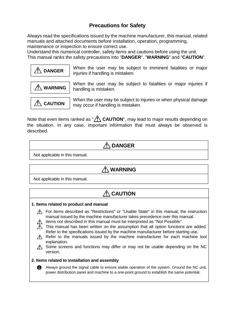
Always read the specifications issued by the machine manufacturer, this manual, relatedmanuals and attached documents before installation, operation, programming,maintenance or inspection to ensure correct use.Understand this numerical controller, safety items and cautions before using the unit.This manual ranks the safety precautions into "DANGER", "WARNING" and "CAUTION".
When the user may be subject to imminent fatalities or majorinjuries if handling is mistaken.
When the user may be subject to fatalities or major injuries ifhandling is mistaken.
When the user may be subject to injuries or when physical damagemay occur if handling is mistaken.
Note that even items ranked as " CAUTION", may lead to major results depending onthe situation. In any case, important information that must always be observed isdescribed.
DANGER Not applicable in this manual.
WARNING Not applicable in this manual.
CAUTION
1. Items related to product and manualFor items described as "Restrictions" or "Usable State" in this manual, the instructionmanual issued by the machine manufacturer takes precedence over this manual.Items not described in this manual must be interpreted as "Not Possible".This manual has been written on the assumption that all option functions are added.Refer to the specifications issued by the machine manufacturer before starting use.Refer to the manuals issued by the machine manufacturer for each machine toolexplanation.Some screens and functions may differ or may not be usable depending on the NCversion.
2. Items related to installation and assemblyAlways ground the signal cable to ensure stable operation of the system. Ground the NC unit,power distribution panel and machine to a one-point ground to establish the same potential.
DANGER
WARNING
CAUTION
CAUTION
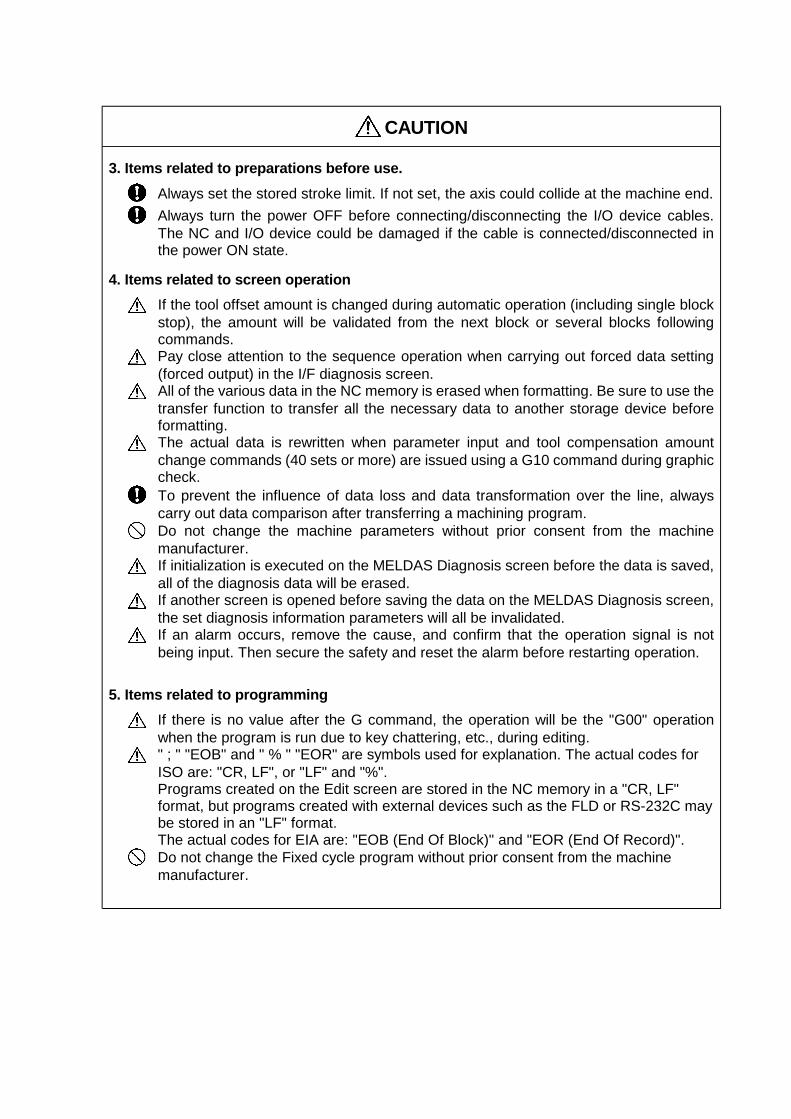
3. Items related to preparations before use.Always set the stored stroke limit. If not set, the axis could collide at the machine end.Always turn the power OFF before connecting/disconnecting the I/O device cables.The NC and I/O device could be damaged if the cable is connected/disconnected inthe power ON state.
4. Items related to screen operationIf the tool offset amount is changed during automatic operation (including single blockstop), the amount will be validated from the next block or several blocks followingcommands.Pay close attention to the sequence operation when carrying out forced data setting(forced output) in the I/F diagnosis screen.All of the various data in the NC memory is erased when formatting. Be sure to use thetransfer function to transfer all the necessary data to another storage device beforeformatting.The actual data is rewritten when parameter input and tool compensation amountchange commands (40 sets or more) are issued using a G10 command during graphiccheck.To prevent the influence of data loss and data transformation over the line, alwayscarry out data comparison after transferring a machining program.Do not change the machine parameters without prior consent from the machinemanufacturer.If initialization is executed on the MELDAS Diagnosis screen before the data is saved,all of the diagnosis data will be erased.If another screen is opened before saving the data on the MELDAS Diagnosis screen,the set diagnosis information parameters will all be invalidated.If an alarm occurs, remove the cause, and confirm that the operation signal is notbeing input. Then secure the safety and reset the alarm before restarting operation.
5. Items related to programmingIf there is no value after the G command, the operation will be the "G00" operationwhen the program is run due to key chattering, etc., during editing." ; " "EOB" and " % " "EOR" are symbols used for explanation. The actual codes forISO are: "CR, LF", or "LF" and "%".Programs created on the Edit screen are stored in the NC memory in a "CR, LF"format, but programs created with external devices such as the FLD or RS-232C maybe stored in an "LF" format.The actual codes for EIA are: "EOB (End Of Block)" and "EOR (End Of Record)".Do not change the Fixed cycle program without prior consent from the machinemanufacturer.
CAUTION
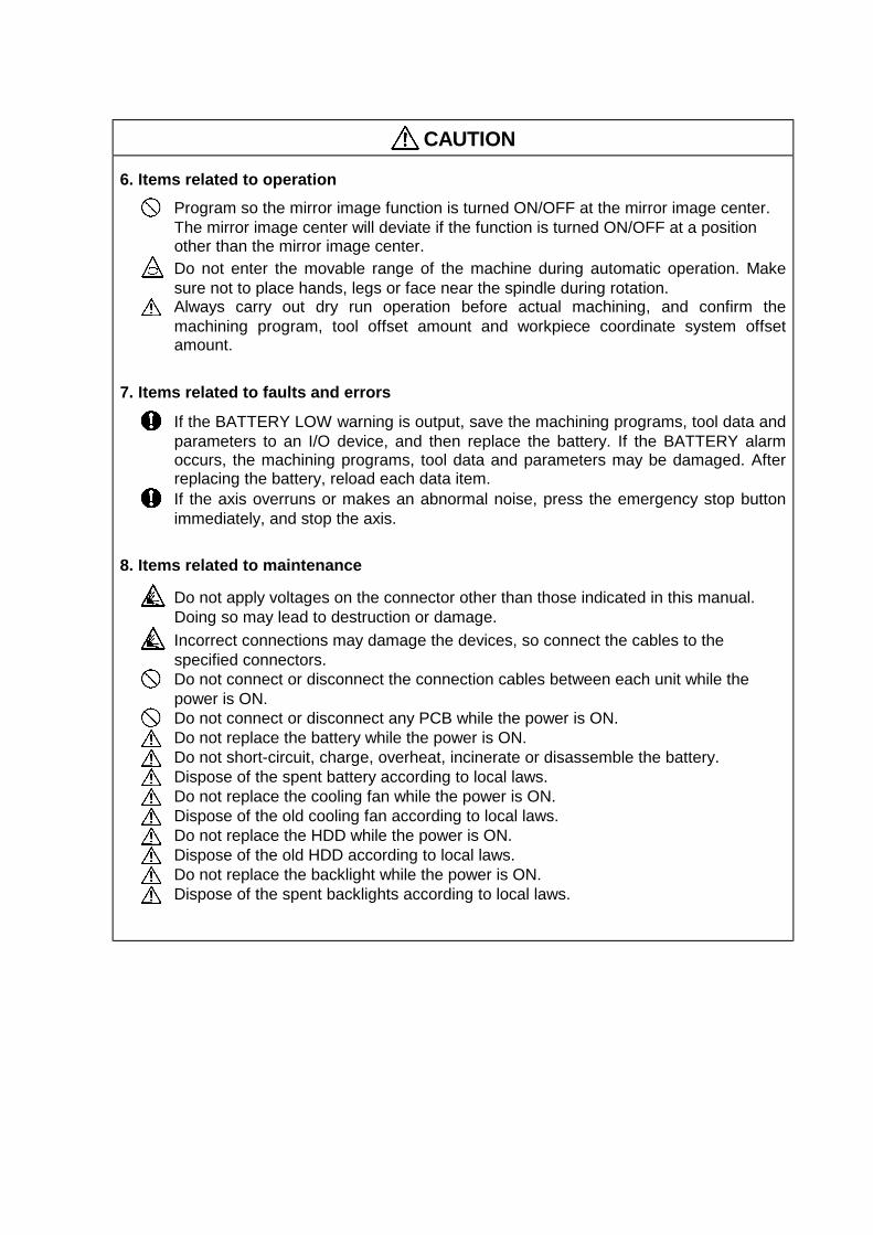
6. Items related to operationProgram so the mirror image function is turned ON/OFF at the mirror image center.The mirror image center will deviate if the function is turned ON/OFF at a positionother than the mirror image center.Do not enter the movable range of the machine during automatic operation. Makesure not to place hands, legs or face near the spindle during rotation.Always carry out dry run operation before actual machining, and confirm themachining program, tool offset amount and workpiece coordinate system offsetamount.
7. Items related to faults and errors
If the BATTERY LOW warning is output, save the machining programs, tool data andparameters to an I/O device, and then replace the battery. If the BATTERY alarmoccurs, the machining programs, tool data and parameters may be damaged. Afterreplacing the battery, reload each data item.If the axis overruns or makes an abnormal noise, press the emergency stop buttonimmediately, and stop the axis.
8. Items related to maintenance
Do not apply voltages on the connector other than those indicated in this manual.Doing so may lead to destruction or damage.Incorrect connections may damage the devices, so connect the cables to thespecified connectors.Do not connect or disconnect the connection cables between each unit while thepower is ON.Do not connect or disconnect any PCB while the power is ON.Do not replace the battery while the power is ON.Do not short-circuit, charge, overheat, incinerate or disassemble the battery.Dispose of the spent battery according to local laws.Do not replace the cooling fan while the power is ON.Dispose of the old cooling fan according to local laws.Do not replace the HDD while the power is ON.Dispose of the old HDD according to local laws.Do not replace the backlight while the power is ON.Dispose of the spent backlights according to local laws.
i
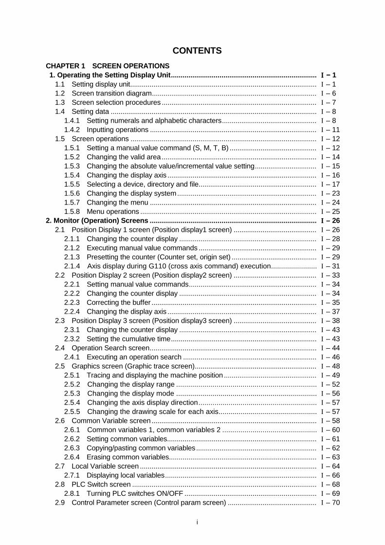
CONTENTSCHAPTER 1 SCREEN OPERATIONS 1. Operating the Setting Display Unit........................................................................... IIII −−−− 1
1.1 Setting display unit................................................................................................ I – 11.2 Screen transition diagram..................................................................................... I – 61.3 Screen selection procedures ................................................................................ I – 71.4 Setting data .......................................................................................................... I – 8
1.4.1 Setting numerals and alphabetic characters................................................. I – 81.4.2 Inputting operations ...................................................................................... I – 11
1.5 Screen operations ................................................................................................ I – 121.5.1 Setting a manual value command (S, M, T, B) ............................................. I – 121.5.2 Changing the valid area................................................................................ I – 141.5.3 Changing the absolute value/incremental value setting................................ I – 151.5.4 Changing the display axis ............................................................................. I – 161.5.5 Selecting a device, directory and file............................................................. I – 171.5.6 Changing the display system........................................................................ I – 231.5.7 Changing the menu ...................................................................................... I – 241.5.8 Menu operations ........................................................................................... I – 25
2. Monitor (Operation) Screens ...................................................................................... IIII – 262.1 Position Display 1 screen (Position display1 screen) ........................................... I – 26
2.1.1 Changing the counter display ....................................................................... I – 282.1.2 Executing manual value commands ............................................................. I – 292.1.3 Presetting the counter (Counter set, origin set) ............................................ I – 292.1.4 Axis display during G110 (cross axis command) execution....................... I – 31
2.2 Position Display 2 screen (Position display2 screen) ........................................... I – 332.2.1 Setting manual value commands.................................................................. I – 342.2.2 Changing the counter display ....................................................................... I – 342.2.3 Correcting the buffer ..................................................................................... I – 352.2.4 Changing the display axis ............................................................................. I – 37
2.3 Position Display 3 screen (Position display3 screen) ........................................... I – 382.3.1 Changing the counter display ....................................................................... I – 432.3.2 Setting the cumulative time........................................................................... I – 43
2.4 Operation Search screen...................................................................................... I – 442.4.1 Executing an operation search ..................................................................... I – 46
2.5 Graphics screen (Graphic trace screen)............................................................... I – 482.5.1 Tracing and displaying the machine position ................................................ I – 492.5.2 Changing the display range ...................................................................... I – 522.5.3 Changing the display mode ...................................................................... I – 562.5.4 Changing the axis display direction........................................................... I – 572.5.5 Changing the drawing scale for each axis................................................. I – 57
2.6 Common Variable screen..................................................................................... I – 582.6.1 Common variables 1, common variables 2 ............................................... I – 602.6.2 Setting common variables............................................................................. I – 612.6.3 Copying/pasting common variables.............................................................. I – 622.6.4 Erasing common variables............................................................................ I – 63
2.7 Local Variable screen ........................................................................................... I – 642.7.1 Displaying local variables.............................................................................. I – 66
2.8 PLC Switch screen ............................................................................................... I – 682.8.1 Turning PLC switches ON/OFF .................................................................... I – 69
2.9 Control Parameter screen (Control param screen) .............................................. I – 70
ii
2.9.1 Turning Control parameters ON/OFF ........................................................... I – 712.9.2 Control parameter details.............................................................................. I – 71
3. Setup Screens ............................................................................................................. IIII – 763.1 Tool Wear Data screen (Tool wear data screen)................................................ I – 76
3.1.1 Setting the tool wear data ............................................................................. I – 783.1.2 Erasing the tool wear data ............................................................................ I – 79
3.2 Tool Data screen (Too data screen)................................................................. I – 813.2.1 Setting the tool data.................................................................................. I – 833.2.2 Erasing the tool data................................................................................. I – 843.2.3 Measuring the tool length.......................................................................... I – 86
3.3 Tool Life Management screen (Tool life manage screen)................................. I – 903.3.1 Tool life management I.......................................................................... I – 913.3.2 Tool life management II ........................................................................ I – 96
3.4 Coordinate System Offset screen (Coord offset screen)...................................... I – 1013.4.1 Setting the coordinate system offset data..................................................... I – 1033.4.2 Erasing the coordinate system offset data.................................................... I – 1043.4.3 Setting the workpiece coordinate zero point ................................................. I – 1043.4.4 Setting the manual value command ............................................................. I – 1053.4.5 Changing the coordinate system display ...................................................... I – 105
3.5 Data Input/Output screen (Input/Output screen) .................................................. I – 1063.5.1 Selecting a device, directory and file............................................................. I – 1093.5.2 Transferring a file.......................................................................................... I – 1163.5.3 Comparing files (Compare)........................................................................... I – 1183.5.4 Erasing a file ................................................................................................. I – 1193.5.5 Changing a file name (Rename)................................................................... I – 1203.5.6 Creating a directory....................................................................................... I – 1213.5.7 Formatting an FLD........................................................................................ I – 1213.5.8 List of file names........................................................................................... I – 1223.5.9 Edit lock B and C .......................................................................................... I – 1233.3.10 Data protect keys.......................................................................................... I – 124
3.6 Parameter screens ............................................................................................... I – 1263.6.1 Setting the parameters ................................................................................. I – 1293.6.2 Copying/pasting parameters......................................................................... I – 130
3.7 User parameter details ......................................................................................... I – 1323.7.1 Axis Parameter (Axis param screen) ............................................................ I – 1333.7.2 Setup Parameter (Setup param screen) ................................................... I – 1353.7.3 Input/Output Parameter (I/O param screen)................................................. I – 1413.7.4 Barrier Data (Barrier data screen)............................................................. I – 1453.7.5 RS-232C I/O device parameter setting examples and cable connections.... I – 146
4. Edit Screens ................................................................................................................. IIII – 1474.1 Edit screen (Edit screen) ...................................................................................... I – 147
4.1.1 Creating a new machining program.............................................................. I – 1514.1.2 Editing a program ......................................................................................... I – 1534.1.3 Creating MDI data......................................................................................... I – 156
4.2 Editing operations................................................................................................. I – 1574.2.1 Changing the display .................................................................................... I – 1574.2.2 Rewriting data............................................................................................... I – 1584.2.3 Inserting data ................................................................................................ I – 1594.2.4 Copying/pasting data .................................................................................... I – 1604.2.5 Deleting data................................................................................................. I – 161
iii
4.2.6 Searching for character strings..................................................................... I – 1634.2.7 Replacing character strings .......................................................................... I – 164
5. Diagnosis Screens....................................................................................................... IIII – 1655.1 Hardware and Software Configuration screen (H/W S/W config screen)............. I – 1655.2 Option Display screen (Option display screen)..................................................... I – 1675.3 I/F Diagnosis screen (I/F diagnosis screen) ......................................................... I – 168
5.3.1 Displaying the PLC device data .................................................................... I – 1715.3.2 Carrying out modal output............................................................................. I – 1725.3.3 Carrying out one-shot output ........................................................................ I – 1745.3.4 Diagnosis when an emergency stop status occurs....................................... I – 174
5.4 Amplifier Monitor screen (Amp monitor screen) ................................................... I – 1765.4.1 Servo axis unit display items......................................................................... I – 1785.4.2 Spindle unit display items.............................................................................. I – 1815.4.3 Display items for the power supply unit ........................................................ I – 1875.4.4 Clearing the alarm history............................................................................. I – 188
5.5 Alarm Message screen (Alarm message screen)................................................. I – 1895.6 MELDAS Diagnosis screen (MELDAS diagn screen)......................................... I – 191
5.6.1 Saving the MELDAS diagnosis information .............................................. I – 1925.6.2 Initializing the MELDAS diagnosis information .......................................... I – 1925.6.3 MELDAS Diagnosis Parameter screen (MELDAS diagn screen) .............. I – 193
6. Maintenance Screens .................................................................................................. IIII – 1996.1 Maintenance screen ............................................................................................. I – 199
6.1.1 Formatting the NC memory....................................................................... I – 2016.1.2 Backing up the NC SRAM information ...................................................... I – 201
6.2 Absolute Position Setting screen (Abs posn set screen) ..................................... I – 2026.2.1 Selecting the axis.......................................................................................... I – 2066.2.2 Displaying the Help screen ....................................................................... I – 206
6.3 Ladder Monitor screen (PLC LADDER screen) ................................................ I – 210
CHAPTER 2 MACHINE OPERATIONS 1. Operation State .......................................................................................................... IIIIIIII −−−− 2
1.1 Operation state transition diagram....................................................................... II − 21.2 Power OFF ...................................................................................................... II − 21.3 Not ready......................................................................................................... II − 31.4 Ready .............................................................................................................. II − 3
1.4.1 Reset....................................................................................................... II − 31.4.2 Automatic operation start......................................................................... II − 31.4.3 Automatic operation pause...................................................................... II − 41.4.4 Automatic operation stop......................................................................... II − 4
2. Indicator Lamps..................................................................................................... IIIIIIII −−−− 52.1 NC unit ready................................................................................................... II − 52.2 Automatic operation busy ............................................................................. II − 52.3 Automatic operation start busy ........................................................................ II − 52.4 Automatic operation pause busy...................................................................... II − 52.5 Return to reference point ................................................................................. II − 52.6 NC alarm ......................................................................................................... II − 52.7 M00 ................................................................................................................ II − 52.8 M01 ................................................................................................................ II − 62.9 M02/M30.......................................................................................................... II − 6
iv
3. Reset Switch and Emergency Stop Button ......................................................... IIIIIIII −−−− 73.1 Reset switch .................................................................................................... II − 73.2 Emergency stop button.................................................................................... II − 7
4. Operation Mode ..................................................................................................... IIIIIIII −−−− 84.1 Mode select switch .......................................................................................... II − 84.2 Jog feed mode................................................................................................. II − 94.3 Rapid traverse mode ....................................................................................... II − 104.4 Reference point return mode ........................................................................... II − 114.5 Incremental feed mode.................................................................................... II − 134.6 Handle feed mode ........................................................................................... II − 144.7 Program run mode........................................................................................... II − 154.8 MDI operation mode ........................................................................................ II − 16
5. Operation Panel Switches in Operation Mode .................................................... IIIIIIII −−−− 175.1 Rapid traverse override ................................................................................... II − 175.2 Cutting feed override ....................................................................................... II − 175.3 Manual feedrate............................................................................................... II − 175.4 Handle/incremental feed magnification factor .................................................. II − 185.5 Handle feed axis selection ............................................................................... II − 185.6 Manual pulse generator ................................................................................... II − 185.7 Cycle start and feed hold ................................................................................. II − 195.8 Feed axis selection .......................................................................................... II − 19
6. Operation Switch Functions and Other Functions ............................................. IIIIIIII −−−− 206.1 All axes machine lock ...................................................................................... II − 206.2 Each axis machine lock ................................................................................... II − 206.3 Display lock ..................................................................................................... II − 206.4 Miscellaneous function lock ............................................................................. II − 216.5 Single block ..................................................................................................... II − 216.6 Dry run............................................................................................................. II − 216.7 Manual override ............................................................................................... II − 216.8 Override cancel ............................................................................................... II − 216.9 Optional stop ................................................................................................... II − 226.10 Optional block skip .......................................................................................... II − 226.11 Manual absolute .............................................................................................. II − 236.12 Mirror image .................................................................................................... II − 246.13 Error defect...................................................................................................... II − 256.14 Chamfering...................................................................................................... II − 256.15 Follow-up function............................................................................................ II − 256.16 Axis removal .................................................................................................... II − 256.17 Manual/automatic synchronous feed ............................................................... II − 256.18 Handle interruption .......................................................................................... II − 26
6.18.1 Outline..................................................................................................... II − 266.18.2 Interruptible conditions ............................................................................ II − 266.18.3 Interruption effective axis......................................................................... II − 276.18.4 Axis movement speed resulting from interruption .................................... II − 276.18.5 Path resulting after handle interruption .................................................... II − 286.18.6 Handle interruption in nose R compensation ........................................... II − 306.18.7 Interrupt amount reset ............................................................................. II − 316.18.8 Operation procedure................................................................................ II − 32
6.19 Deceleration check .......................................................................................... II − 336.20 Miscellaneous command high-speed output .................................................... II − 376.21 Rapid traverse constant inclination acceleration/deceleration.......................... II − 39
v
CHAPTER 3 MAINTENANCE 1. Confirming the Operation ..................................................................................... IIIIIIIIIIII −−−− 1
1.1 Confirming the axis movement direction .......................................................... III − 11.2 Confirming the limit switch operation ............................................................... III − 1
2. Confirming the Drive Section ............................................................................... IIIIIIIIIIII −−−− 2 3. Adjusting the Dog-type Reference Point Return ................................................. IIIIIIIIIIII −−−− 3
3.1 Dog-type reference point return....................................................................... III − 33.2 Reference point return parameters .................................................................. III − 53.3 Dog-type reference point return adjustment procedures.................................. III − 9
4. Absolute Position Detection ................................................................................. IIIIIIIIIIII −−−− 104.1 Absolute position detection system.................................................................. III − 104.2 Starting up absolute position detection ............................................................ III − 124.3 Procedures for initializing for the dog-type absolute position detection ............ III − 134.4 Procedures for the dogless-type detection; initializing with machine end
stopper method................................................................................................ III − 144.4.1 Random point type (Screen operation method) ....................................... III − 144.4.2 Grid point point type (Screen operation method) ..................................... III − 154.4.3 Random point type (automatic dogless-type)........................................... III − 164.4.4 Grid point point type (automatic dogless-type)......................................... III − 174.4.5 Notes....................................................................................................... III − 18
4.5 Procedures for the dogless-type detection; initializing with marked pointalignment method ............................................................................................ III − 19
4.5.1 Random point type (Screen operation method) ....................................... III − 194.5.2 Grid point type (Screen operation method) .............................................. III − 204.5.3 Notes....................................................................................................... III − 21
4.6 Various settings for dogless-type absolute position detection.......................... III − 224.7 Absolute position detection check function ...................................................... III − 24
5. Daily Maintenance ................................................................................................... IIIIIIIIIIII −−−− 255.1 Daily inspection................................................................................................ III − 25
5.1.1 Checking the external view...................................................................... III − 255.1.2 Checking the inside of the control panel .................................................. III − 25
5.2 Replacement ................................................................................................... III − 265.2.1 Replacing the battery............................................................................... III − 265.2.2 Replacing the backlights.......................................................................... III − 285.2.3 Replacing the cooling fan ........................................................................ III − 295.2.4 Replacing the hard disk drive (HDD) ....................................................... III − 30
5.3 Cleaning and handling ..................................................................................... III − 335.3.1 Escutcheon.............................................................................................. III − 335.3.2 Floppy disk .............................................................................................. III − 335.3.3 Hard disk drive ........................................................................................ III − 375.3.4 LCD panel ............................................................................................... III − 375.3.5 PCMCIA Card.......................................................................................... III − 38
6. Fault Diagnosis and Action .................................................................................... IIIIIIIIIIII −−−− 396.1 Checking the fault occurrence status............................................................... III − 396.2 Fault examples ................................................................................................ III − 40
vi
CHAPTER 4 APPENDICES Appendix 1. Fixed Cycle Programs ....................................................................... IVIVIVIV −−−− 1
1.1 Parameters for fixed cycle program operation ................................................. IV − 11.2 Inputting/outputting fixed cycle programs......................................................... IV − 21.3 Standard fixed cycle subprogram .................................................................... IV − 3
Appendix 2. Operation Messages.......................................................................... IVIVIVIV −−−− 142.1 Position display-related operation messages................................................... IV − 142.2 Operation search-related operation messages ................................................ IV − 142.3 Graphic display-related operation messages ................................................... IV − 142.4 Compensation-related (tool compensation, coordinate system offset)
operation messages ........................................................................................ IV − 152.5 Data input/output-related operation messages ................................................ IV − 152.6 Parameter-related operation messages........................................................... IV − 182.7 Tool-related operation messages .................................................................... IV − 182.8 Manual tool length measurement-related operation messages ....................... IV − 182.9 Editing-related operation messages ................................................................ IV − 192.10 Diagnosis-related operation messages............................................................ IV − 202.11 Absolute position detection-related operation messages ................................. IV − 202.12 Maintenance-related operation messages ....................................................... IV − 212.13 Other operation messages .............................................................................. IV − 21
Appendix 3. Alarm Messages .................................................................................. IVIVIVIV −−−− 223.1 Errors during operation (M ) ....................................................................... IV − 22
3.1.1 Operation Errors (M01) ............................................................................. IV − 223.1.2 Absolute position return again (M02) ........................................................ IV − 313.1.3 Interference check alarm (M03) ................................................................ IV − 313.1.4 Interference area alarm (M04) .................................................................. IV − 31
3.2 Stop Codes (T ).......................................................................................... IV − 323.3 Messages related to servo............................................................................... IV − 35
3.3.1 Servo alarms (S ) ................................................................................ IV − 353.3.2 Servo warnings (s ).............................................................................. IV − 40
3.4 Messages related to spindle ............................................................................ IV − 423.4.1 Spindle alarms (S ) .............................................................................. IV − 423.4.2 Spindle warnings (s ) ........................................................................... IV − 47
3.5 MCP alarms..................................................................................................... IV − 483.5.1 MCP alarms (Y ) .................................................................................. IV − 483.5.2 MCP warnings (y ) ............................................................................... IV − 50
3.6 Messages related to system ............................................................................ IV − 513.6.1 System alarms (Z ) .............................................................................. IV − 513.6.2 System warnings (z ) ........................................................................... IV − 54
3.7 Alarms related to user PLC (U ) ................................................................. IV − 553.8 Program errors (P ) ................................................................................. IV − 56

CHAPTER 1 SCREEN OPERATIONS
CHAPTER 1 SCREEN OPERATIONS1. Operating the Setting Display Unit
I – 1
1. Operating the Setting Display Unit
1.1 Setting display unit
(1) Setting display unit appearanceAn LCD display is used for the screen displays.Operations such as screen transition and data setting are carried out with the NC keyboard.The setting display unit is configured of the LCD display, various keys and menu keys as shownbelow.The drawing below shows a horizontal layout of the LCD display and NC keyboard, but these canalso be arranged vertically.
11. INPUT key12. RESET key
9. SHIFT key
5. Data setting keys (alphabet, numerals, symbols)
READY LED6. Window operation keys1. Function keys
INPUTCALC
SHIFT
RESET
2. Page changeover key 11. Cursor keys
LCD display
13. Menu keys
4. Menu changeover keys
7. Data correction keys
3. Previous screen display key
8. Lower case input key
(System changeover)
The following keys are provided on the keyboard.
Key type Key Operation
MONITOR This displays the menu of the screen related to"operations". ( → Refer to "2. Monitor Screens".)
SETUP This displays the menu of the screen related to "setup".( → Refer to "3. Setup Screens".)
EDIT This displays the menu of the screen related to "editing".( → Refer to "4. Edit Screens".)
DIAGN This displays the menu of the screen related to "diagnosis".( → Refer to "5. Diagnosis Screens".)
1. Function key
MAINTE This displays the menu of the screen related to"maintenance". ( → Refer to "6. Maintenance Screens".)
2. Pagechangeoverkey
Previous pagekey
When the displayed contents cover several pages, thisdisplays the contents of the previous page. The " " markat the top of the screen indicates that there is a previouspage.
Next page key When the displayed contents cover several pages, thisdisplays the contents of the next page. The " " mark at thetop of the screen indicates that there is a next page.
CHAPTER 1 SCREEN OPERATIONS1. Operating the Setting Display Unit
I – 2
Key type Key Operation
BACK
Previous screendisplay key
This redisplays the previously displayed screen.3. Previousscreendisplay key(Systemchangeover) $ → $
Systemchangeover key
When using a multi-system NC, this displays the data of thenext system. The screen does not change if it is a systemcommon screen or when only one system is used.
4. Menuchangeoverkey
(left side) This changes the operation menu for the displayed screento the current screen group screen selection menu.This is also used to cancel the menu operations of thedisplayed screen.
(right side) When all of the menus cannot be displayed at once, thisdisplays the menus not currently displayed.The " " and " " marks at the bottom of the screen indicatethat there are menus not displayed.
5. Data settingkey
A B C D E F
G H I J K L
M N O P Q R
S T U V W X
Y Z
0 1 2 3 4 5
6 7 8 9
+ – = / . ;
etc.
These keys are pressed to set alphabetic characters,numerals and operation symbols, etc.
6. Windowoperationkey
This displays a window. (Not used)
This changes the active window. (Not used)
This displays the menu for selecting operations on thewindow. (Not used)
? Help key This displays the help. (Not used.)
7. Datacorrectionkey
INSERT
Data insert key
This inputs the data insertion mode. When a data settingkey is pressed, a character is inserted in front of the currentcursor position.
The overwrite mode is entered when the DELETE ,
C·B ESC , INPUT , cursor or Tab, etc., keys are pressed,or when the screen is changed.
DELETE
Data delete key
This deletes the character just before the cursor position inthe data setting area.
C·B ESC Cancel key
This cancels the setting in the data setting area.
8. Lower caseinput key
LOWER CASE This changes the input between upper case and lower casealphabetic characters.
9. SHIFT key SHIFT This validates the setting on the lower line of data settingkey.
CHAPTER 1 SCREEN OPERATIONS1. Operating the Setting Display Unit
I – 3
Key type Key Operation10. Cursor key ↑ ↓ This moves the cursor up or down one when setting data in
the screen display items.
← → This moves the cursor one item to the left or right whenselecting data in the screen display items.← at cursor left end : Moves to the right end of previous
line.→ at cursor right end: Moves to left end of next line.
← → This moves the data input cursor one character to the left orright in the data setting area.
11. INPUT key INPUT This fixes the data in the data setting area, and writes it tothe internal data. The cursor moves to the next position.
12. RESET key RESET This resets the NC.
13. Menu keys This changes the screen and displays the data.
(2) Display configurationThe screen is displayed with the following type of configuration:
< >
4
20
1 Screen group display
General-purpose data display area
System No. Screen name
Operation state/Operation message Alarm/warning (one line)
Operation status
Menu (two lines)
Data setting area
Number of lines
When using one system, the system No. is not displayed at the upper left of the screen. The numberof the currently displayed system is displayed only when two or more systems are being used.
: There is a previous page. : There is a next page.
Alarm :The currently occurring alarm orwarning with the highest priority isdisplayed.
Message :The setting and display functionstatus is displayed.
The key input details are displayed.Press the INPUT key to fix the data.
: Indicates that a menu is hiddenon the left side.
: Indicates that a menu is hiddenon the right side.
Displays the type of screen group.The selected group is highlighted.
Displays the menu for changing thescreens.
Indicates a menu that is hidden. (Shifts the menu to the left/right.)
CHAPTER 1 SCREEN OPERATIONS1. Operating the Setting Display Unit
I – 4
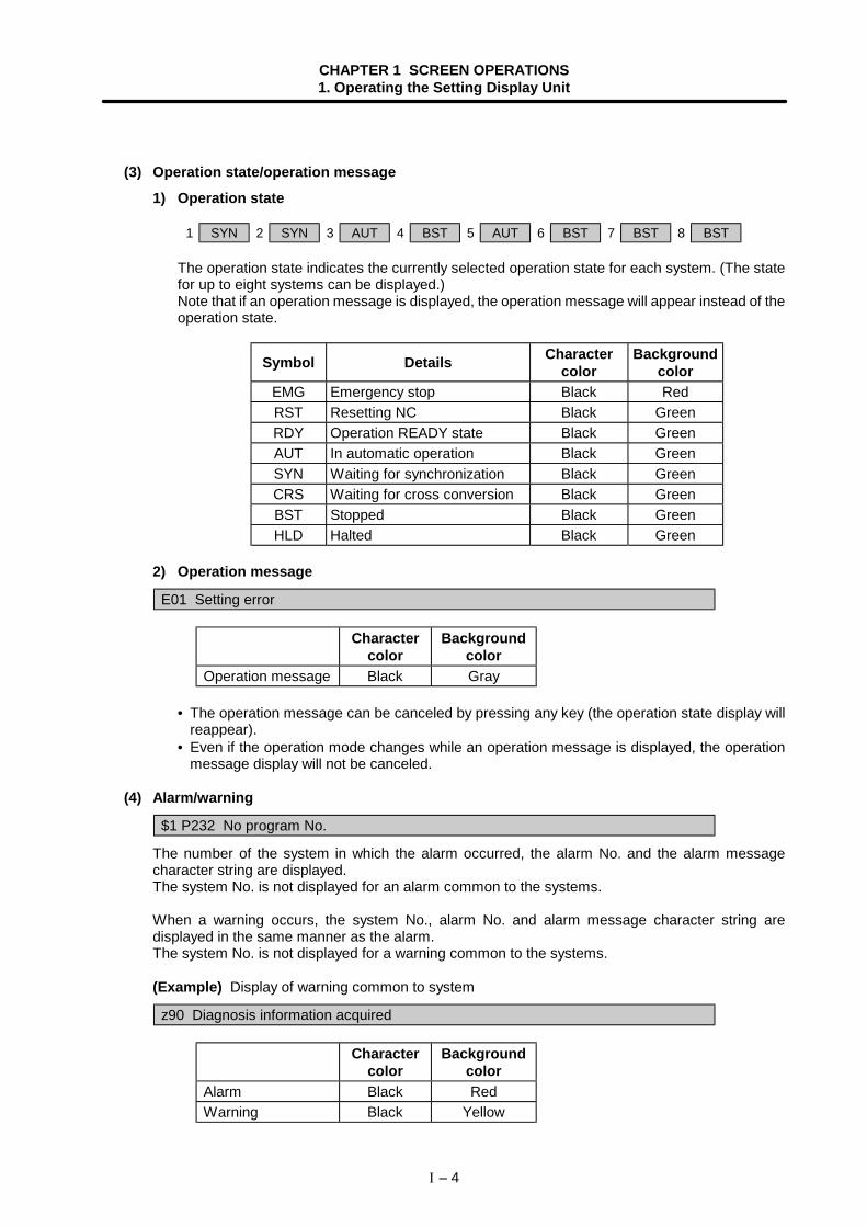
(3) Operation state/operation message
1) Operation state
1 SYN 2 SYN 3 AUT 4 BST 5 AUT 6 BST 7 BST 8 BST
The operation state indicates the currently selected operation state for each system. (The statefor up to eight systems can be displayed.)Note that if an operation message is displayed, the operation message will appear instead of theoperation state.
Symbol Details Charactercolor
Backgroundcolor
EMG Emergency stop Black RedRST Resetting NC Black GreenRDY Operation READY state Black GreenAUT In automatic operation Black GreenSYN Waiting for synchronization Black GreenCRS Waiting for cross conversion Black GreenBST Stopped Black GreenHLD Halted Black Green
2) Operation message
E01 Setting error
Charactercolor
Backgroundcolor
Operation message Black Gray
• The operation message can be canceled by pressing any key (the operation state display willreappear).
• Even if the operation mode changes while an operation message is displayed, the operationmessage display will not be canceled.
(4) Alarm/warning
$1 P232 No program No.
The number of the system in which the alarm occurred, the alarm No. and the alarm messagecharacter string are displayed.The system No. is not displayed for an alarm common to the systems.
When a warning occurs, the system No., alarm No. and alarm message character string aredisplayed in the same manner as the alarm.The system No. is not displayed for a warning common to the systems.
(Example) Display of warning common to system
z90 Diagnosis information acquired
Charactercolor
Backgroundcolor
Alarm Black RedWarning Black Yellow
CHAPTER 1 SCREEN OPERATIONS1. Operating the Setting Display Unit
I – 5
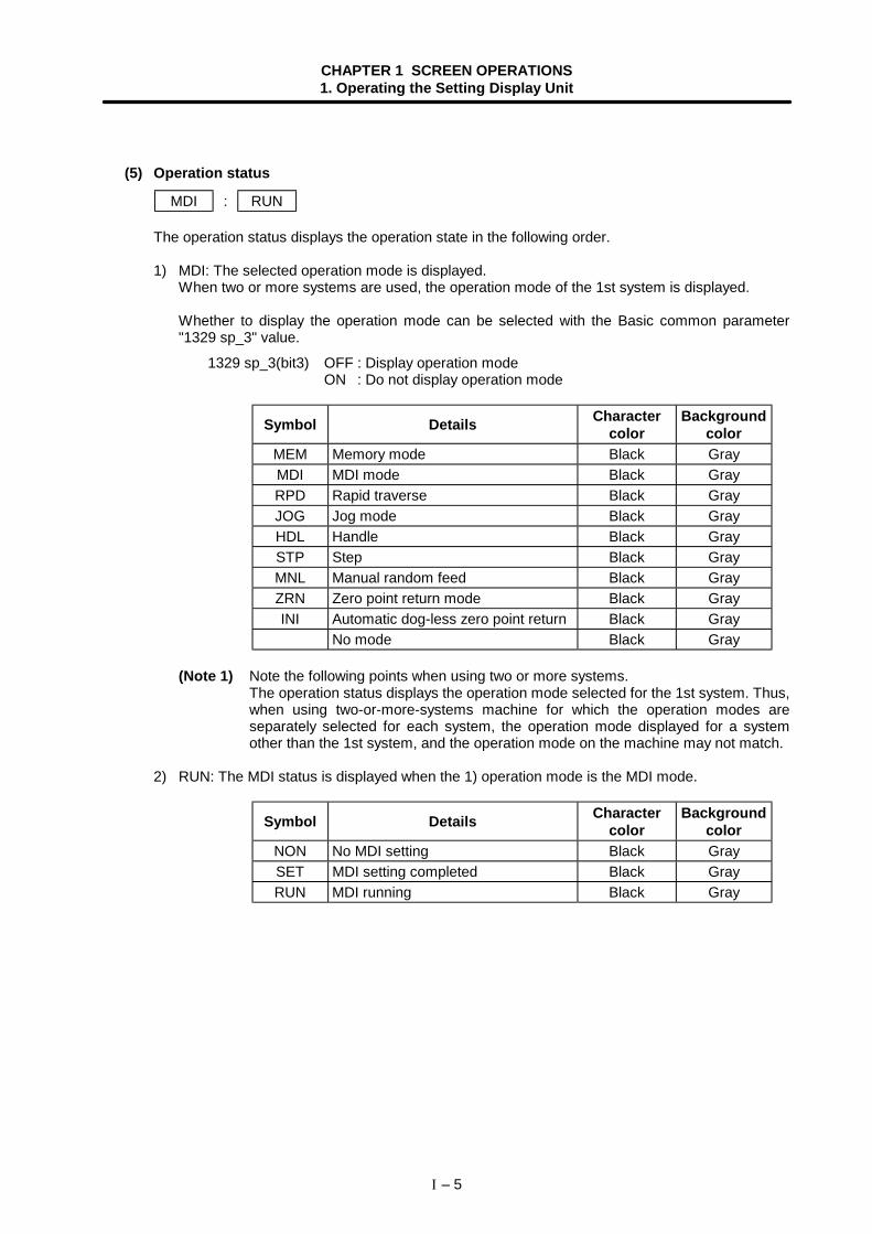
(5) Operation status
MDI : RUN
The operation status displays the operation state in the following order.
1) MDI: The selected operation mode is displayed.When two or more systems are used, the operation mode of the 1st system is displayed.
Whether to display the operation mode can be selected with the Basic common parameter"1329 sp_3" value.
1329 sp_3(bit3) OFF : Display operation modeON : Do not display operation mode
Symbol Details Charactercolor
Backgroundcolor
MEM Memory mode Black GrayMDI MDI mode Black GrayRPD Rapid traverse Black GrayJOG Jog mode Black GrayHDL Handle Black GraySTP Step Black GrayMNL Manual random feed Black GrayZRN Zero point return mode Black GrayINI Automatic dog-less zero point return Black Gray
No mode Black Gray
(Note 1) Note the following points when using two or more systems.The operation status displays the operation mode selected for the 1st system. Thus,when using two-or-more-systems machine for which the operation modes areseparately selected for each system, the operation mode displayed for a systemother than the 1st system, and the operation mode on the machine may not match.
2) RUN: The MDI status is displayed when the 1) operation mode is the MDI mode.
Symbol Details Charactercolor
Backgroundcolor
NON No MDI setting Black GraySET MDI setting completed Black GrayRUN MDI running Black Gray
CHAPTER 1 SCREEN OPERATIONS1. Operating the Setting Display Unit
I – 6
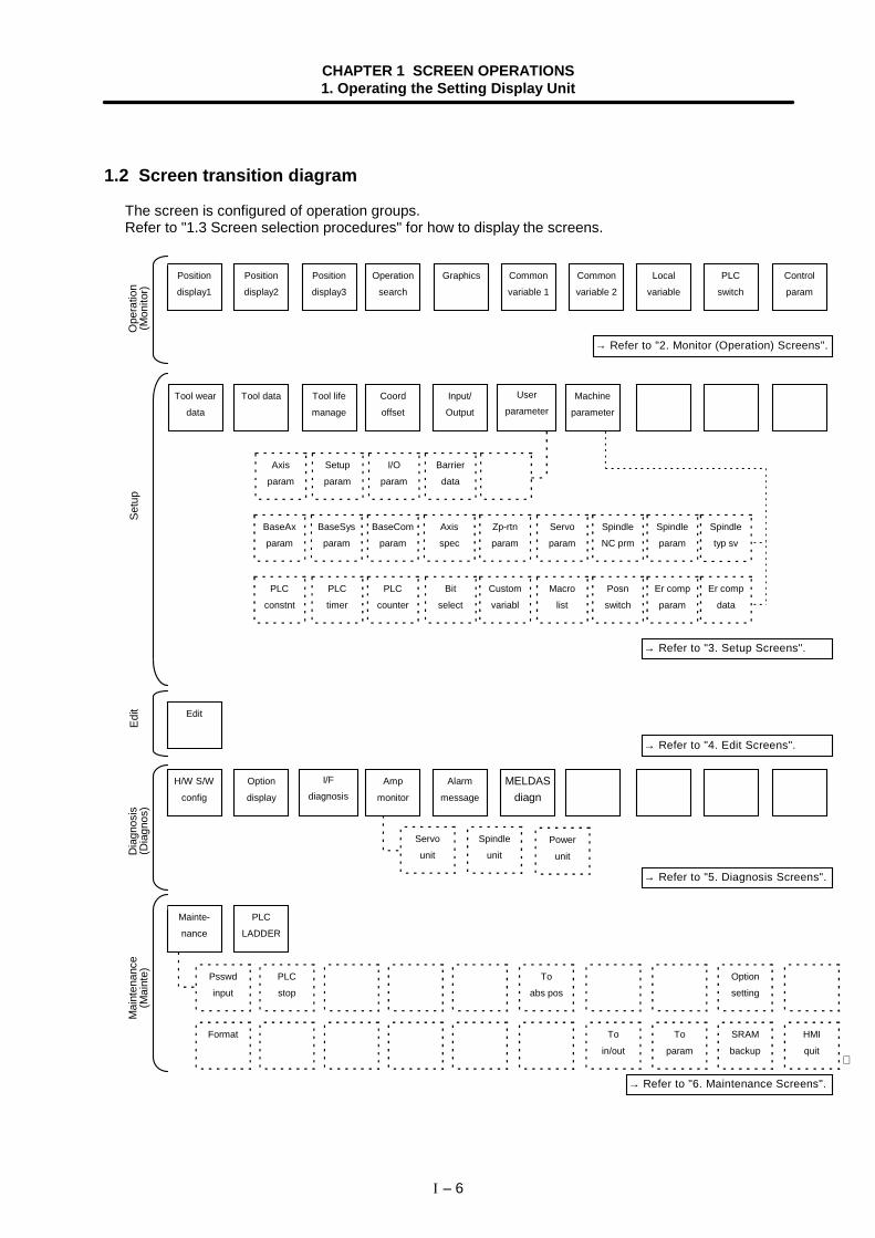
1.2 Screen transition diagram
The screen is configured of operation groups.Refer to "1.3 Screen selection procedures" for how to display the screens.
PLC
switch
Local
variable
Common
variable 2
Common
variable 1
GraphicsOperation
search
Position
display3
Position
display2
Position
display1
Control
param
Ope
ratio
n(M
onito
r)
→ Refer to "2. Monitor (Operation) Screens".
Machine
parameter
User
parameterInput/
Output
Coord
offset
Tool life
manage
Tool data
Barrier
data
I/O
param
Setup
param
Axis
param
→ Refer to "3. Setup Screens".
Setu
p
→ Refer to "5. Diagnosis Screens".
MELDASdiagn
Alarm
message
Amp
monitor
I/F
diagnosisOption
display
H/W S/W
config
Servo
unitPower
unit
Spindle
unitDia
gnos
is(D
iagn
os)
To
abs pos
PLC
stop
Psswd
input
PLC
LADDER
Mainte-
nance
→ Refer to "6. Maintenance Screens".
Mai
nten
ance
(Mai
nte)
Edit
→ Refer to "4. Edit Screens".
Edit
Option
setting
To
param
To
in/out
Format HMI
quit
SRAM
backup∗
Zp-rtn
param
Axis
spec
BaseCom
param
BaseSys
param
BaseAx
param
Servo
param
Spindle
NC prm
Spindle
param
Spindle
typ sv
Tool wear
data
Custom
variabl
Bit
select
PLC
counter
PLC
timer
PLC
constnt
Macro
list
Posn
switch
Er comp
param
Er comp
data
CHAPTER 1 SCREEN OPERATIONS1. Operating the Setting Display Unit
I – 7
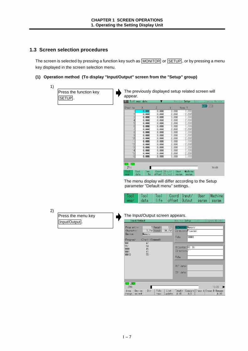
1.3 Screen selection procedures
The screen is selected by pressing a function key such as MONITOR or SETUP , or by pressing a menukey displayed in the screen selection menu.
(1) Operation method (To display "Input/Output" screen from the "Setup" group)
1)The previously displayed setup related screen willappear.
The menu display will differ according to the Setupparameter "Default menu" settings.
2)The Input/Output screen appears.
Press the function keySETUP .
Press the menu keyInput/Output .
CHAPTER 1 SCREEN OPERATIONS1. Operating the Setting Display Unit
I – 8
1.4 Setting data
1.4.1 Setting numerals and alphabetic characters
(1) Operation methodThe data is basically set with the following methods:
1) Menu selection2) Number selection3) Cursor movement4) Data key input5) INPUT key input
An example for setting the data on the Tool wear data screen is shown below.
1) Menu selection
The Tool wear data screen appears.The cursor appears at the Tool wear data.
2) Number selection
The cursor moves to the designated number.
3) Cursor movement
The cursor moves.
4) Data key input
The data is set in the data setting area.
12. 205
Press the menu key for the itemto be set. Menu Tool wear
If the setting item has a number(No.), designate that number. Menu Ofset No. 11 INPUT
If there is no number or whenmoving up/down/left/right, movethe cursor with cursor keys.
Up/down: Move with ↑ , ↓
Left/right: Move with ← →
Set data with the numeral keys oralphabet keys, etc. 1 2 . 2 0 5
CHAPTER 1 SCREEN OPERATIONS1. Operating the Setting Display Unit
I – 9
5) INPUT key inputThe contents in the data setting area are fixed, the datasetting is processed, and the results appear on thescreen.The cursor moves to the next position.
(Note 1) The contents in the data setting area are only displayed until the INPUT key is pressed.These contents are invalidated if the screen is changed. The data is written into thememory when the INPUT key is pressed.
(Note 2) Special settings may be required depending on the data type. Refer to each item.(Note 3) The cursor may move to the right of the display item depending on the data type.(Note 4) If an illegal key is set, an error occurs when INPUT is pressed. Reset the correct data.
(2) Operations in the data setting areaThe key is input at the position where the cursor is displayed. If a cursor is not displayed, the keyinput is invalid.When a key is input, the data appears at the cursor position, and the cursor moves one characterspace to the right.
→ / ← keys: Moves the cursor one character to the left or right.
1)
2)The cursor moves one character space to the right.
INSERT key: Enters the insert mode.1)
The cursor moves in the data setting area.
2)The data is inserted, and the cursor moves to the right.
(Note) The overwrite mode is entered when the DELETE , C·B ESC keys are pressed, or when thescreen is changed.
Press the INPUT key.
The cursor is at the positionshown on the right. 1 2 3 7 7 7 4 5 64
Press the → key.
1 2 3 7 7 7 4 5 65
Move the cursor to the positionwhere the data is to be inserted.
1 2 3 4 5 64
Press the INSERT key, andthen the data keys. INSERT 7 7 7
1 2 3 7 7 7 4 5 64
CHAPTER 1 SCREEN OPERATIONS1. Operating the Setting Display Unit
I – 10
DELETE key: Deletes the character in front of the cursor.
1)The cursor moves in the data setting area.
2)The character in front of the cursor is deleted, and thecursor moves.
C·B ESC key: Deletes all characters in the data setting area.
1)All characters in the data setting area are deleted, andthe cursor moves to the left end.
(3) Cursor operations on the screen
If a cursor is displayed on the screen, data is set in the data setting area and the INPUT key ispressed, the data appears at the cursor position on the screen. The cursor moves to the nextposition.The following keys can be used to move the cursor with the cursor keys.
↑ : Moves the cursor to the previous line.↓ : Moves the cursor to the next line.← : Moves the cursor one item to the left.→ : Moves the cursor one item to the right.
Move the cursor to the positionwhere the data is to be deleted.
Press the DELETE key.
Press the C·B ESC key.
1 2 3 7 7 4 5 64
1 2 3 7 7 4 5 64
CHAPTER 1 SCREEN OPERATIONS1. Operating the Setting Display Unit
I – 11
1.4.2 Inputting operations
In addition to the method of directly inputting numeric data for specific data settings, a method to input theoperation results using arithmetical operators and function symbols can be used.
(1) Input methodNumeric values, function symbols, operators and parentheses ( ) are combined and set in the datasetting area.The operation results appear when the INPUT key is pressed. If the INPUT key is pressed again,the data is processed and displayed on the screen. The contents in the data setting area are erased.
Examples of operator settings, and results
Function symbols, setting examples and results
Operation Settingexample
Operationresults Function Function
symbolSetting
exampleOperation
results
Addition =100+50 150.000 Absolutevalue ABS =ABS (50−60) 10
Subtraction =100−50 50.000 Square root SQRT =SQRT (3) 1.732Multiplication =12.3∗ 4 49.200 Sine SIN =SIN (30) 0.5Division =100/3 33.333 Cosine COS =COS (15) 0.966
Tangent TAN =TAN (45) 1Function =1.2∗
(2.5+SQRT(4)) 5.4Atangent ATAN =ATAN (1.3) 0.915
(2) Operation examples
1)
The operation results appear in the data setting area.2 4 0
2)The contents of the data setting area are fixed, the datasetting is processed and the results appear on thescreen.The cursor moves to the next position.
(3) Notes for using operators and functionsDivision : Zero division causes an error.Square root : If the value in the parentheses is negative, an error occurs.Triangle function : The unit of angle θ is degree (°).Atangent : −90 < operation results < 90.
(4) Restrictions• Always use "=" for the first character.• Do not use the following characters as the second character or last character.
Invalid as second character: ∗ , /, ) Invalid as last character: ∗ , /, (, +, -
• Make sure that the left parentheses and right parentheses are balanced.• The 360° limit does not apply on the angle. SIN (500) is interpreted as SIN (140).
Set as shown below, and pressthe INPUT key.
=12∗ 20 INPUT
Press the INPUT key again.
CHAPTER 1 SCREEN OPERATIONS1. Operating the Setting Display Unit
I – 12
1.5 Screen operations
1.5.1 Setting a manual value command (S, M, T, B)
The spindle function S, miscellaneous function M, tool function T and 2nd miscellaneous function Bcommands can be set with screen operations. This carries out the S, M, T, B command executionprogram by commanding the operations with key inputs on the screen.
(1) Screens in which manual value commands can be set(Target commands that can be set are shown in parentheses.)
• Position display1 screen, Position display2 screen (S, M, T, B)• Tool data screen (M, T)• Coord offset screen (M, T)
(Note) On the Position display1 screen and Position display2 screen, manual value commandscan be issued by inputting the address.
(2) Conditions for manual value commands• The manual value command option must be valid.• S, M, T or B command must not be in execution.
(3) Operation methods (When executing T31 with a manual value command)
1)The manual value command mode is entered.The cursor appears, and the menu is highlighted.The command value executed last is displayed on thescreen.
S1 1000S2 2000
2)The cursor moves.
S1 1000S2 2000
3)The command is executed.The menu highlight is removed, and the cursordisappears.
(Note 1) On the position display1 and 2 screens, by inputting an address key such as S 1 , M
or T instead of steps 1) and 2), the cursor appears at the corresponding displayposition.
(Note 2) To set a negative value, add a "−" in front of the numeric value. Refer to "(4) Manualvalue command setting and output range". When using a BCD output type or unsignedbinary output type, a value converted into a positive value is set.
Using the ↑ , ↓ keys, movethe cursor to the position to beset. (Note 1)
Select the menuManual value .
Set the numeric value, and pressthe INPUT key.(Note 2)
1500 INPUT
CHAPTER 1 SCREEN OPERATIONS1. Operating the Setting Display Unit
I – 13
(4) Manual value command setting and output rangeFor the S, M, T and B commands, the type of data output from the NC unit to the user PLC is presetto one of the following by the Machine parameters.
• BCD output• Unsigned binary data• Signed binary data
The following table shows the manual value command setting and output range according to thespecifications of the three types.
BCD/unsigned binary Signed binaryS 0 to 99999999 −99999999 to 99999999M 0 to 99999999 −99999999 to 99999999T 0 to 99999999 −99999999 to 99999999B 0 to 99999999 −99999999 to 99999999
(Note 1) When using the BCD output type or unsigned binary output type, a value converted intoa positive value is output.
(Example)
(Note 2) If a value exceeding the setting range is set, the high-order data is dropped.(Example)
Set 5 1 is dropped.
(5) Number of displayed commands
Command Number of displayed commands
S Follows the value set for the Machine parameter "Sfig".(Maximum six commands)
M Follows the value set for the Machine parameter "Mfig".(Maximum four commands)
T One commandB One command
(Note 1) The S command value is displayed with the name set with the Machine parameter"Sname".
(Note 2) The final command value is displayed for the S command value.
(6) Other notes 1) If the program command format is the MELDAS 600 Series standard format and a macro
interruption command code (M96, M97) or subprogram call code (M98, M99) is commanded,the command will not be processed.
2) The manual value command mode is canceled if the following operations are carried out beforepressing the INPUT key.
• When the Manual value menu key is pressed again.
• When the key is pressed. • When another menu key is pressed. • When the screen is changed.
Setting value: M-100 Output value: M 100
M 1234 M 2345
CHAPTER 1 SCREEN OPERATIONS1. Operating the Setting Display Unit
I – 14
1.5.2 Changing the valid area
In screens where the display area is split, such as the Position display3 screen, Input/Output screen orEdit screen, the area containing the screen must be validated before the display can be changed or thedata set.The display area can be changed by pressing the menu key ( Area change ). There are screens that arechanged with the Tab keys ( ← , → ).After changing, all operations such as data setting and cursor movement are valid in that area.
(1) To change with the menu keys.If an Area change menu is provided, such as on the Position display3 screen or Input/Output screen,the area is changed with the menu keys.
1) When left side of Position display3 screen is valid. (Refer to the screens above.)
The right area is validated.
(2) To change with Tab keysThe area is changed with the Tab keys on the Common variable (1, 2) screen, Local variable screenand Parameter screen, etc.
Press the menu Area change .
Left display area is valid. Right display area is valid.
CHAPTER 1 SCREEN OPERATIONS1. Operating the Setting Display Unit
I – 15
1.5.3 Changing the absolute value/incremental value setting
The mode (absolute value setting mode/incremental value setting mode) for setting the data can beselected with the menus.Once the mode is selected, it is saved even when the screen is changed and after the power is turnedOFF.The absolute value setting mode is selected as the default.
(1) Screen for changing the absolute value/incremental value• Position display3 screen (when common variables are displayed)• Common variable (1, 2) screen• Tool wear data screen• Tool data screen• Coord offset screen
(2) Operation method(To change the absolute value setting mode to the incremental value setting mode)
1)The display on the screen changes to incrementalvalue. (Following figure.)Settings can be made in the incremental value mode.
/Inc Abs Abs / Inc
(3) Differences between the absolute value setting mode and incremental value setting mode
(Example 1) To change the G54 workpiece coordinate system as shown below.
G54X1Y1 0.000
G54
0.000X1Y1
G54X=-50.G54
M
X=-150.
-50.000-150.000
When /Inc Abs , then setting value : −50
When Abs / Inc , then setting value : 100
Press the menu Abs/Inc .
Basic machine coordinate system
External offset (EXT)
Before changes After changes
CHAPTER 1 SCREEN OPERATIONS1. Operating the Setting Display Unit
I – 16
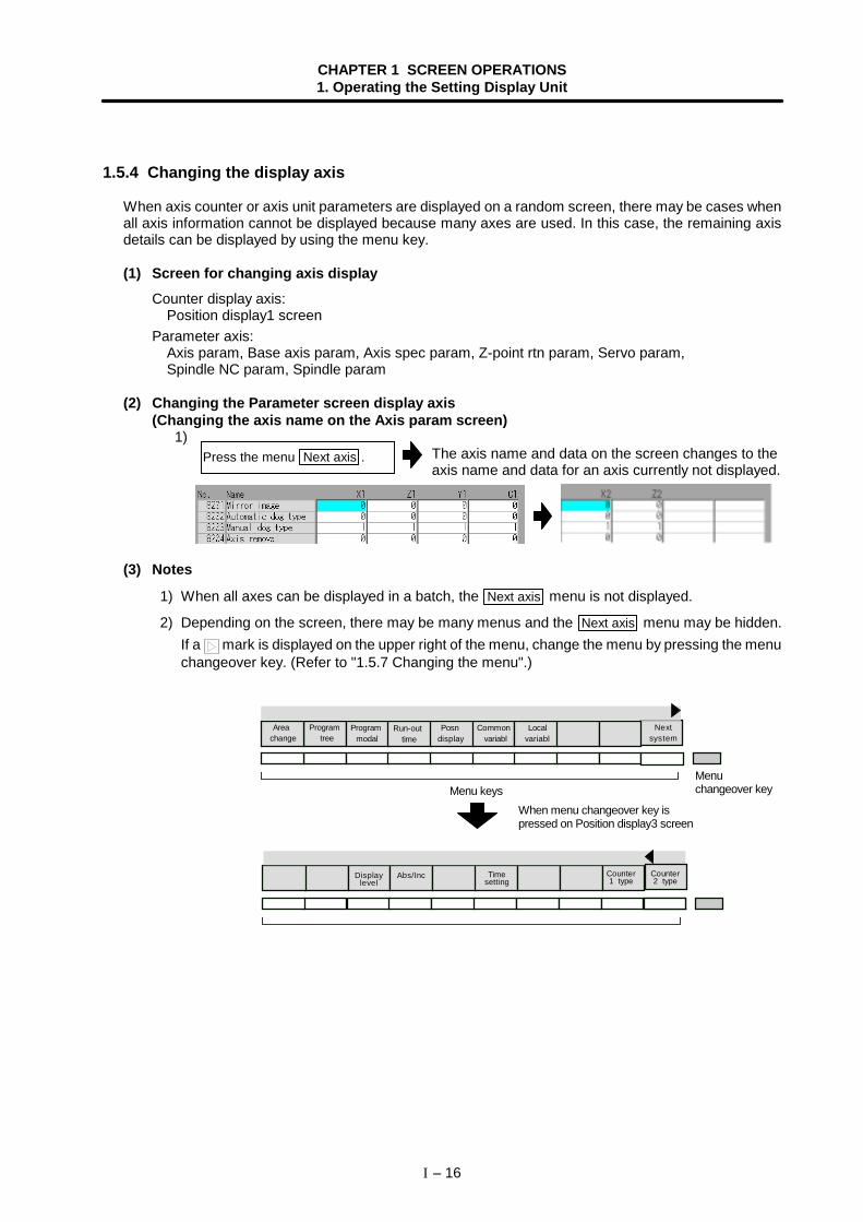
1.5.4 Changing the display axis
When axis counter or axis unit parameters are displayed on a random screen, there may be cases whenall axis information cannot be displayed because many axes are used. In this case, the remaining axisdetails can be displayed by using the menu key.
(1) Screen for changing axis displayCounter display axis:
Position display1 screenParameter axis:
Axis param, Base axis param, Axis spec param, Z-point rtn param, Servo param,Spindle NC param, Spindle param
(2) Changing the Parameter screen display axis(Changing the axis name on the Axis param screen)
1)The axis name and data on the screen changes to theaxis name and data for an axis currently not displayed.
(3) Notes
1) When all axes can be displayed in a batch, the Next axis menu is not displayed.
2) Depending on the screen, there may be many menus and the Next axis menu may be hidden.If a mark is displayed on the upper right of the menu, change the menu by pressing the menuchangeover key. (Refer to "1.5.7 Changing the menu".)
Areachange
Program tree
Program modal
Run-out time
Posndisplay
Common variabl
Localvariabl
Nextsystem
Displaylevel
Abs/Inc Timesetting
Counter1 type
Counter2 type
Press the menu Next axis .
Menu keysWhen menu changeover key ispressed on Position display3 screen
Menuchangeover key
CHAPTER 1 SCREEN OPERATIONS1. Operating the Setting Display Unit
I – 17
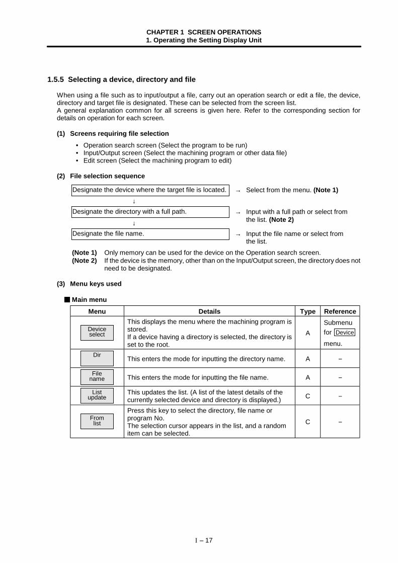
1.5.5 Selecting a device, directory and file
When using a file such as to input/output a file, carry out an operation search or edit a file, the device,directory and target file is designated. These can be selected from the screen list.A general explanation common for all screens is given here. Refer to the corresponding section fordetails on operation for each screen.
(1) Screens requiring file selection• Operation search screen (Select the program to be run)• Input/Output screen (Select the machining program or other data file)• Edit screen (Select the machining program to edit)
(2) File selection sequence
(Note 1) Only memory can be used for the device on the Operation search screen.(Note 2) If the device is the memory, other than on the Input/Output screen, the directory does not
need to be designated.
(3) Menu keys used
Main menuMenu Details Type Reference
Deviceselect
This displays the menu where the machining program isstored.If a device having a directory is selected, the directory isset to the root.
ASubmenufor Device
menu.Dir This enters the mode for inputting the directory name. A −
Filename This enters the mode for inputting the file name. A −
Listupdate
This updates the list. (A list of the latest details of thecurrently selected device and directory is displayed.) C −
Fromlist
Press this key to select the directory, file name orprogram No.The selection cursor appears in the list, and a randomitem can be selected.
C −
→ Select from the menu. (Note 1)
→ Input with a full path or select fromthe list. (Note 2)
→ Input the file name or select fromthe list.
Designate the device where the target file is located.
Designate the directory with a full path.
Designate the file name.↓
↓
CHAPTER 1 SCREEN OPERATIONS1. Operating the Setting Display Unit
I – 18
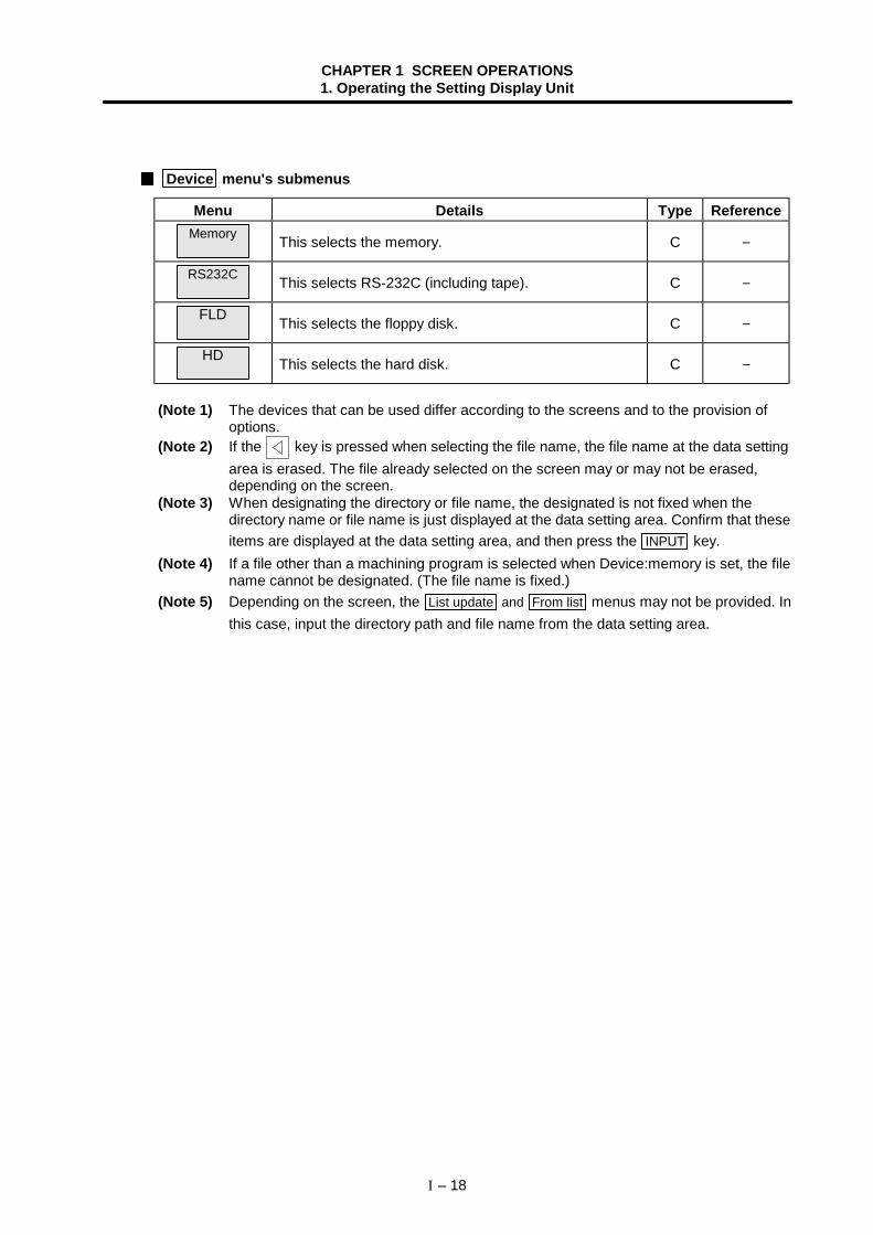
Device menu's submenus
Menu Details Type ReferenceMemory This selects the memory. C −
RS232C This selects RS-232C (including tape). C −
FLD This selects the floppy disk. C −
HD This selects the hard disk. C −
(Note 1) The devices that can be used differ according to the screens and to the provision ofoptions.
(Note 2) If the key is pressed when selecting the file name, the file name at the data settingarea is erased. The file already selected on the screen may or may not be erased,depending on the screen.
(Note 3) When designating the directory or file name, the designated is not fixed when thedirectory name or file name is just displayed at the data setting area. Confirm that theseitems are displayed at the data setting area, and then press the INPUT key.
(Note 4) If a file other than a machining program is selected when Device:memory is set, the filename cannot be designated. (The file name is fixed.)
(Note 5) Depending on the screen, the List update and From list menus may not be provided. Inthis case, input the directory path and file name from the data setting area.
CHAPTER 1 SCREEN OPERATIONS1. Operating the Setting Display Unit
I – 19
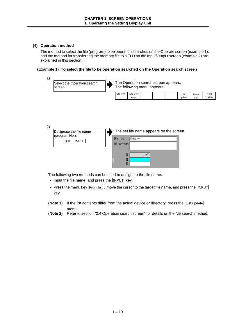
(4) Operation methodThe method to select the file (program) to be operation searched on the Operate screen (example 1),and the method for transferring the memory file to a FLD on the Input/Output screen (example 2) areexplained in this section.
(Example 1) To select the file to be operation searched on the Operation search screen
1)The Operation search screen appears.The following menu appears.
NB srch Listupdate
Fromlist
NB srchexec
Nextsystem
2)The set file name appears on the screen.
The following two methods can be used to designate the file name. • Input the file name, and press the INPUT key.
• Press the menu key From list , move the cursor to the target file name, and press the INPUTkey.
(Note 1) If the list contents differ from the actual device or directory, press the List updatemenu.
(Note 2) Refer to section "2.4 Operation search screen" for details on the NB search method.
Designate the file name(program No.). 1001 INPUT
Select the Operation searchscreen.
CHAPTER 1 SCREEN OPERATIONS1. Operating the Setting Display Unit
I – 20
(Example 2) To select a program file to be transferred from the memory to a FLD on theInput/Output screen
Select the memory program file as the transfer origin.
1)The Input/Output screen appears.The following menu appears.
Areachange
Deviceselect
Dir Filename
Listupdate
TrnsfrA -> B • • •
2)The A display area is validated.
3)The cursor appears at "A: Device".The following menu appears.Memory RS232C FLD A: HD D:
4)The selected device name appears.When memory is selected, "Program" appears in thedirectory as a default.
5)The mode for inputting the directory name is entered.(The cursor appears at "Directory:".)The following menu appears. When selecting a deviceother than the memory, refer to the procedures forselecting the transfer destination FLD file.
Fromlist
Program Param PLC prog
NC data
6)The set directory path appears on the screen.
The following two methods can be used to set the directory path. • Set the directory path (full path) in the data setting area, and press the INPUT key.
• Press the menu key From list , move the cursor to the target directory, and press the INPUTkey.
Select the Input/Output screen.
Press Area change , andvalidate the A: (transfer origin)display area.
Press the menuDevice select .
Press the menu Memory .
Select the menu Dir .
Select the directory path(program) from the menu.
A : Device : Memory Directory : Program File :
A : Device : Memory Directory : Program File :
CHAPTER 1 SCREEN OPERATIONS1. Operating the Setting Display Unit
I – 21
7)The mode for inputting the file name is entered.(The cursor appears at "File:".)The following menu appears.Fromlist
Systemparam
Param(Text)
Param(Bin)
8)
The following two methods can be used to designate the file name. • Input the file name, and press the INPUT key.
• Press the menu key From list , move the cursor to the target file name, and press the INPUTkey.
Designate the FLD program file as the transfer destination.
9)The B display area is validated and the cursor appears.
10)The following menu appears.
Memory RS232C FLD A: HD D:
11)The selected device name appears.
12)The mode for inputting the directory name is entered.The following menu appears.
Fromlist
Press the menu File name .
Designate the file name. 1001 INPUT
Press Area change , andvalidate the B: (transferdestination) display area.
Press the menuDevice select .
Press the menu FLD .
Select the menu Dir .
A : Device : Memory Directory : PROGRAM File : 1001
A : Device : FLD A: Directory : File :
CHAPTER 1 SCREEN OPERATIONS1. Operating the Setting Display Unit
I – 22
13)The input directory path appears.
The following two methods can be used to set the directory path. • Set the directory path (full path) in the data setting area, and press the INPUT key.
• Press the menu key From list , move the cursor to the target directory, and press the INPUTkey.
14)The mode for inputting the file name is entered.The following menu appears.Fromlist
15)
The following two methods can be used to designate the file name. • Input the file name, and press the INPUT key.
• Press the menu key From list , move the cursor to the target file name, and press the INPUTkey.
Input the directory path. /PROGRAM/TEST INPUT
Press the menu File name .
Input the file name. precut INPUT
A : Device : FLD A: Directory : /PROGRAM/TEST File : precut
A : Device : FLD A: Directory : /PROGRAM/TEST File :
CHAPTER 1 SCREEN OPERATIONS1. Operating the Setting Display Unit
I – 23
1.5.6 Changing the display system
When using multiple systems, information such as the counter value and modals can be changed tothose for another system. Once the system is changed, the information for that system is displayed evenwhen the screen is changed.The 1st system is selected when the power is turned ON.When using a single system, and when the screen is common for all systems, the system cannot bechanged.
(1) Operation method(To change the right area of the Position display3 screen to the 2nd system)
1)The right area is validated.
(Note) Refer to "1.5.2 Changing the valid area" for how to change the area.
2)The details displayed on the right is the 2nd systeminformation."$2" appears.
(Note 1) By pressing the Next system menu, the system can be changed in the same manneras the $ → $ key.
(Note 2) The system No. changes in the following order:
n: Maximum No. within valid system numbers. (Maximum: $8)
Press the menu Area change ,and validate the right area.
Press the $ → $ key.
$1 → $2 → $3 → ··· $n
CHAPTER 1 SCREEN OPERATIONS1. Operating the Setting Display Unit
I – 24
1.5.7 Changing the menu
The menu can be used to select screens and to select functions or setting items. Up to ten menus can bedisplayed at once.To select the menu, use the menu key below the menu display.To change the menu, use the menu changeover key.
(Refer to the following figures.) key : The operation menu is canceled.
The screen selection menu for the currently displayed screen group appears.The display for the currently displayed menu is highlighted.
key : When there are more than 11 menus, this key displays the remaining menus.(Menu change) This key can be used when " " or " " is displayed at the upper right of the menu.
TraceON
Programdisplay
Erase Displayrange
Displaymode
Operatesearch
Toparam
Nextsystem
Menu keysMenuchangeover key
Areachange
Programtree
Programmodal
Run-outtime
Posndisplay
Localvariabl
Common var-1
Common var-2
Nextsystem
When menu changeover key is pressedon Position display3 screen
Displaylevel
Abs/Inc Timesetting
Counter1 type
Counter2 type
When menu changeover key is pressed again
Menu keysMenuchangeover key
Areachange
Programtree
Programmodal
Run-outtime
Posndisplay
Commonvar-1
Localvariabl
Commonvar-2
Nextsystem
This indicates that there are morethan 11 menus, and that there aremenus before the currentlydisplayed menu.
This indicates that there are morethan 11 menus, and that there aremenus following the currentlydisplayed menu.
Menu key
Menudisplay
Menu changeover key
CHAPTER 1 SCREEN OPERATIONS1. Operating the Setting Display Unit
I – 25
1.5.8 Menu operations
(1) Menu typesThe menus can be categorized as follow according to the operation after the menu key is pressed.
When the menu key is pressed:A. The menu is highlighted, and the user input standby state is entered. After input, the operation
follows the input details.B. The menu is highlighted, and operation starts.C. Operation starts without the menu highlighted.
In this manual following "2. Monitor (Operation) Screens", this categorization is described as follows.
(Example) Explanation of menus used in Input/Output screen
Menu Details Type Reference
Areachange
This changes the setting area to file setting column A(transfer origin) or file setting column B (transferdestination). The display of the valid area (A or B) ishighlighted.
C
1.5.2 Changingthe valid area
Listupdate
This updates the list. The directory list selected in thecurrently valid file setting column (A or B) is updated. C
TrnsfrA→B
This copies the file in file setting column A (transferorigin) to the file setting column B (transferdestination). (The transfer origin file is not changed.) Amessage appears during transfer and when thetransfer is completed.
B
3.5.2Transferring a file
Stop This interrupts the process (transfer, compare, etc.)during execution. C
(2) Menu displayThe menu that can currently be used appears in the menu display area. A menu name displayed ingray indicates that the menu cannot be used. Depending on the parameter (Setup parameter"Invalid gray menu∗ ") setting, menus that are not used can be set not to display.The following screen shows that the menu used for the modal display is invalid.
Operation when menu is pressed Menu type Reference section
CHAPTER 1 SCREEN OPERATIONS2. Monitor (Operation) Screens
I – 26
2. Monitor (Operation) Screens
2.1 Position Display 1 screen (Position display1 screen)
The counter value of each axis in automatic operation can be referred to on this screen. Furthermore, onthis screen, the counter can be set, and manual values can be commanded.
(1) Display items
Display item Details1. Currently executed
machining programMain O 10 ··· This displays the program No., sequence No. and block No. currently being
executed.Sub O 1234···
When executing a subprogram, the subprogram's program No., sequenceNo., block No., and subprogram's nesting level are displayed.
2. Counter display This displays the counter of the current position and workpiece coordinatespositions, etc.The type of counter displayed can be selected with the menu key.
3. Speed display The speed in the vector direction, currently being moved in, is displayed.4. S, M, T, B
commandsThis displays the command value for the S (spindle speed command value),M (miscellaneous function command value), T (tool command value), and B(2nd miscellaneous function command value).Refer to "1.5.1 Setting a manual value command" for how to set the manualvalue command.
5. Actual spindlerotation speed
The actual rotation speed of the 1st spindle and 2nd spindle is displayed.
6. Buffer display This displays the contents of the machining program currently beingexecuted.The block being executed is highlighted. Refer to "2.2.3 Correcting thebuffer" for details on correcting the buffer.
2. Counter display
6. Buffer display
1. Currently executedmachining program
3. Speed display
4. S, M, T, Bcommands
5. Actual spindlerotation speed
CHAPTER 1 SCREEN OPERATIONS2. Monitor (Operation) Screens
I – 27
(2) Menus
Menu Details Type Reference
Countertype
This displays the submenu for changing the displaycounter. At this time, the same menu as the currentlyselected counter is highlighted.
B2.1.1 Changingthe counterdisplay
Manualvalue
Random values can be input in each data item of S, M,T and B on the screen.When the numeric value is input, the selected S, M, Tand B functions are executed.
A
1.5.1 Setting amanual valuecommand
Counterset
This presets the counter.The current position counter value is set to "0". A
Originset
This sets the origin.The coordinate system is shifted so that the currentposition becomes the zero point of the workpiececoordinate system.
C
2.1.3 Presettingthe counter
Nextsystem
This appears when there are two or more validsystems.The system No. will be incremented by one each timethis menu is pressed.(Note) If the system No. to be displayed next exceeds
the number of valid systems, the informationfor the 1st system will appear.
C
1.5.6 Changingthe displaysystem
BklightOFF
This turns off the entire screen to prevent deteriorationof the LCD screen, etc.The screen reappears when any key is pressed.
C−
CHAPTER 1 SCREEN OPERATIONS2. Monitor (Operation) Screens
I – 28
2.1.1 Changing the counter display
(1) Counter type menusWhen the menu key Counter type is pressed, the following submenu appears. The display contentsof the counter display can be selected from the following types.
Menu Details Type
Currntposn
This displays the currently executed position and the status symbol whenthe position is at a specified position or status. #1 to #4 : 1st to 4th reference point position
] [ : Servo OFF stateMR : Mirror image
> < : Axis removal state
C
Workco posn
This displays the G54 to G59 workpiece coordinate system modal Nos.and the workpiece coordinate position in that workpiece coordinatesystem.
C
Machineposn
This displays the coordinate value of each axis in the basic machinecoordinate system having a characteristic position, specified by themachine, as a zero point.
C
Programposn
This displays the value obtained by subtracting the tool compensationamount compensated for that axis from the position actually beingexecuted for each axis. [Program position] = [Current position] – Tool compensation amount
C
Remaincommand
This displays the remaining distance of the movement command beingexecuted during automatic start or automatic halt. (The remainingdistance is the incremental distance from the current position to the endpoint of that block.)
C
Manualint amt
This displays the amount moved with the manual mode while the manualabsolute switch was OFF.If the Control parameter "Interrupt amt reset" is ON, the interrupt amountis cleared when the reset button is pressed.
C
Er compamnt
This displays the error compensation amount.C
(Note 1) If the key is pressed while the submenu is displayed, the main menu appears.
(2) Operation methods (To display the current position in the counter display.)1)
The following menu appears.Currntposn
Workco posn
Machineposn
Programposn
Remaincommand
Manualint amt • • •
2)
The current position counter appears in the counterdisplay area.
Press the menu keyCounter type .
Press the menu keyCurrnt posn .
CHAPTER 1 SCREEN OPERATIONS2. Monitor (Operation) Screens
I – 29
2.1.2 Executing manual value commands
Each value for S, M, T and B can be set and executed using the menu Manual value .Up to six S commands, four M commands, or one T command or one B command can be set.The manual value command can be set and executed by inputting an address such as S, M or T.Refer to "1.5.1 Setting a manual value command" for the setting method.
2.1.3 Presetting the counter (Counter set, origin set)
Counter set and origin set can be executed on this screen.The counter set can be executed only when the counter display is the current position.
(1) Differences between counter set and origin set
Counter set Origin setFunction The current position counter is cleared to
zero.The coordinate system is shifted so thecurrent position becomes the zero pointof the workpiece coordinate system.This is equivalent to "G92 X0".(When X is the target axis.)
Changes inthe counterdisplay
"0" is displayed only for the currentposition counter.
The current position counter andworkpiece coordinate counters become"0".
Offset − The G92 shift amount is updated.
The counter set mode can also be entered by inputting the axis name address.
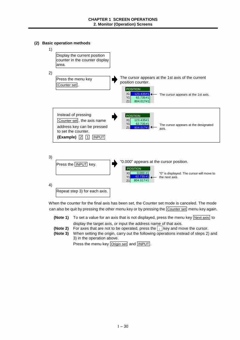
CHAPTER 1 SCREEN OPERATIONS2. Monitor (Operation) Screens
I – 30
(2) Basic operation methods1)
2)The cursor appears at the 1st axis of the currentposition counter.
X1Y1Z1
62.735804.017#1
#1123.435#1
POSITION
Instead of pressingCounter set , the axis name
address key can be pressedto set the counter.(Example) Z 1 INPUT
3)"0.000" appears at the cursor position.
X1Y1Z1 804.017#1
0.000 #1POSITION
62.735 #1
4)
When the counter for the final axis has been set, the Counter set mode is canceled. The modecan also be quit by pressing the other menu key or by pressing the Counter set menu key again.
(Note 1) To set a value for an axis that is not displayed, press the menu key Next axis todisplay the target axis, or input the address name of that axis.
(Note 2) For axes that are not to be operated, press the ↓ key and move the cursor.(Note 3) When setting the origin, carry out the following operations instead of steps 2) and
3) in the operation above.Press the menu key Origin set and INPUT .
X1Y1Z1
123.435#1POSITION
62.735#1804.017#1
Display the current positioncounter in the counter displayarea.
Press the menu keyCounter set .
Press the INPUT key.
Repeat step 3) for each axis.
"0" is displayed. The cursor will move tothe next axis.
The cursor appears at the designatedaxis.
The cursor appears at the 1st axis.
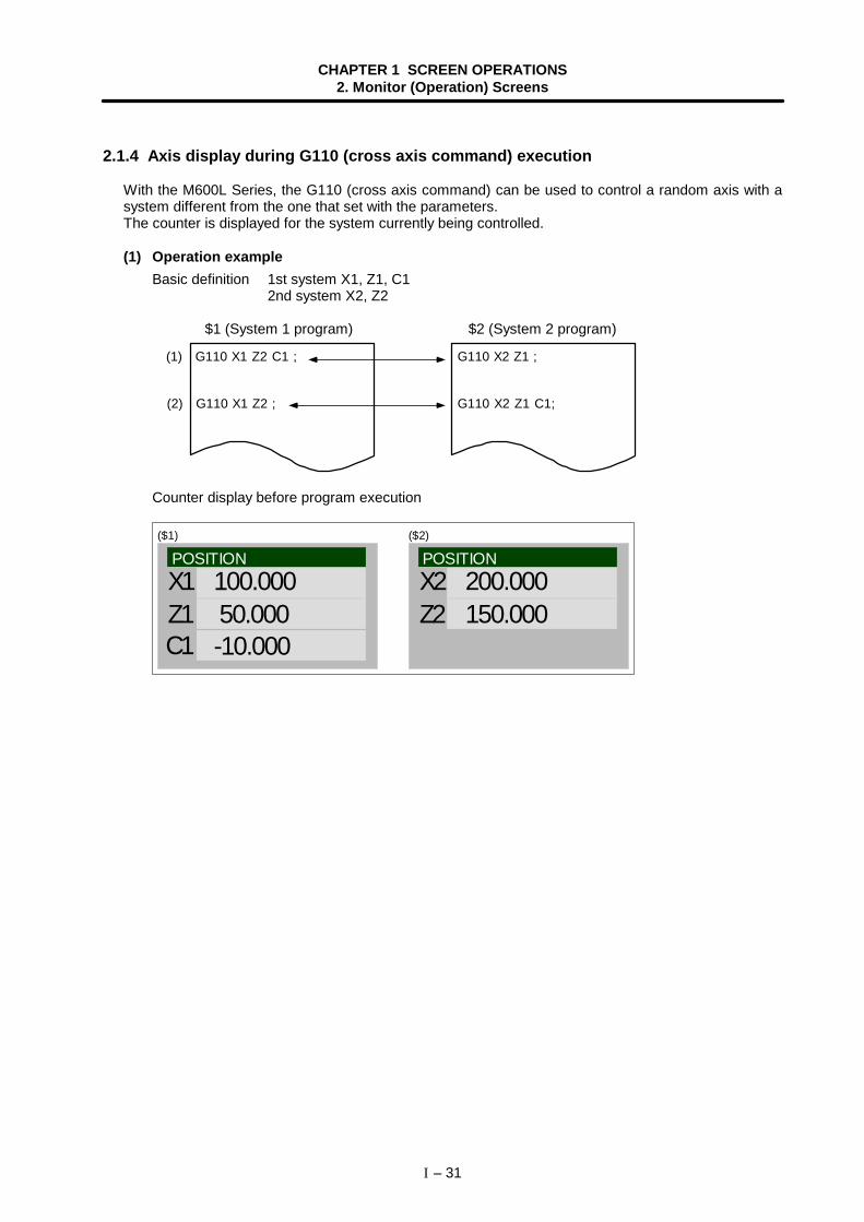
CHAPTER 1 SCREEN OPERATIONS2. Monitor (Operation) Screens
I – 31
2.1.4 Axis display during G110 (cross axis command) execution
With the M600L Series, the G110 (cross axis command) can be used to control a random axis with asystem different from the one that set with the parameters.The counter is displayed for the system currently being controlled.
(1) Operation exampleBasic definition 1st system X1, Z1, C1
2nd system X2, Z2
$1 (System 1 program) $2 (System 2 program)
(1) G110 X1 Z2 C1 ; G110 X2 Z1 ;
G110 X1 Z2 ; G110 X2 Z1 C1;(2)
Counter display before program execution
POSITIONX1Z1C1
100.000 50.000 -10.000
POSITIONX2Z2
200.000 150.000
($1) ($2)
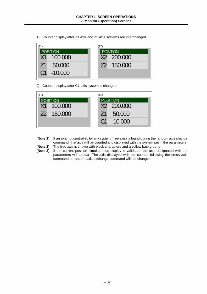
CHAPTER 1 SCREEN OPERATIONS2. Monitor (Operation) Screens
I – 32
1) Counter display after Z1 axis and Z2 axis systems are interchanged
X1Z1C1
100.000 50.000 -10.000
X2Z2
200.000 150.000
($1) ($2)
POSITION POSITION
2) Counter display after C1 axis system is changed
X1Z2
100.000 150.000
X2Z1C1
200.000 50.000 -10.000
($1) ($2)
POSITION POSITION
(Note 1) If an axis not controlled by any system (free axis) is found during the random axis changecommand, that axis will be counted and displayed with the system set in the parameters.
(Note 2) The free axis is shown with black characters and a yellow background.(Note 3) If the current position simultaneous display is validated, the axis designated with the
parameters will appear. The axis displayed with the counter following the cross axiscommand or random axis exchange command will not change.
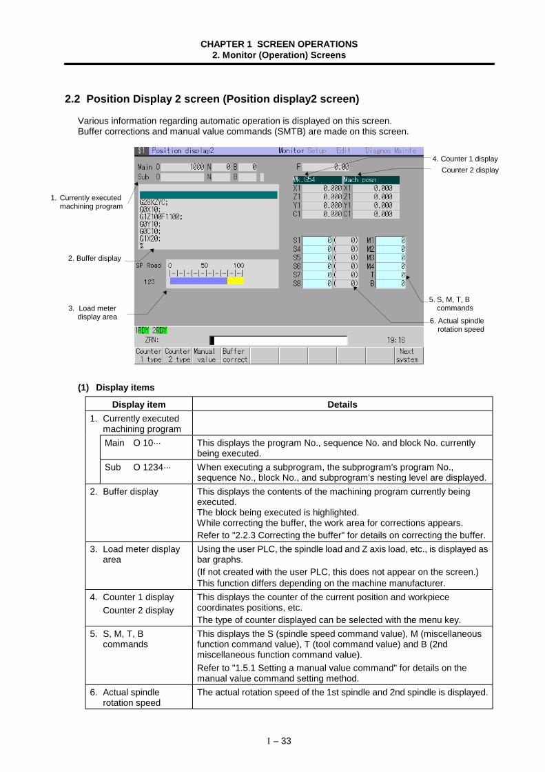
CHAPTER 1 SCREEN OPERATIONS2. Monitor (Operation) Screens
I – 33
2.2 Position Display 2 screen (Position display2 screen)
Various information regarding automatic operation is displayed on this screen.Buffer corrections and manual value commands (SMTB) are made on this screen.
(1) Display items
Display item Details1. Currently executed
machining programMain O 10··· This displays the program No., sequence No. and block No. currently
being executed.Sub O 1234··· When executing a subprogram, the subprogram's program No.,
sequence No., block No., and subprogram's nesting level are displayed.2. Buffer display This displays the contents of the machining program currently being
executed.The block being executed is highlighted.While correcting the buffer, the work area for corrections appears.Refer to "2.2.3 Correcting the buffer" for details on correcting the buffer.
3. Load meter displayarea
Using the user PLC, the spindle load and Z axis load, etc., is displayed asbar graphs.(If not created with the user PLC, this does not appear on the screen.)This function differs depending on the machine manufacturer.
4. Counter 1 displayCounter 2 display
This displays the counter of the current position and workpiececoordinates positions, etc.The type of counter displayed can be selected with the menu key.
5. S, M, T, Bcommands
This displays the S (spindle speed command value), M (miscellaneousfunction command value), T (tool command value) and B (2ndmiscellaneous function command value).Refer to "1.5.1 Setting a manual value command" for details on themanual value command setting method.
6. Actual spindlerotation speed
The actual rotation speed of the 1st spindle and 2nd spindle is displayed.
2. Buffer display
6. Actual spindlerotation speed
3. Load meterdisplay area
5. S, M, T, Bcommands
1. Currently executedmachining program
4. Counter 1 displayCounter 2 display
CHAPTER 1 SCREEN OPERATIONS2. Monitor (Operation) Screens
I – 34
(2) Menus
Menu Details Type ReferenceCounter1 type
Counter2 type
This displays the submenu for changing the displaycounter. At this time, the same menu as the currentlyselected counter is highlighted. C
2.1.1 Changingthe counterdisplay
Manualvalue
Random values can be input in each data item of S, M,T and B on the screen.When the numeric value is input, the selected S, M, Tand B functions are executed.
A
1.5.1 Setting amanual valuecommand
Buffercorrect
This enters the buffer correction mode.B
2.2.3 Correctingthe buffer
Nextsystem
This appears when there are two or more validsystems.The system No. will be incremented by one each timethis menu is pressed.(Note) If the system No. to be displayed next exceeds
the number of valid systems, the informationfor the 1st system will appear.
C
1.5.6 Changingthe displaysystem
2.2.1 Setting manual value commands
Each value for S, M, T and B can be set and executed using the menu Manual value .Up to six S commands, four M commands, or one T command or B command can be set. (Note 1)The manual value command can also be set and executed by inputting an address such as S, M or T,etc.Refer to "1.5.1 Setting a manual value command" for the setting method.
(Note 1) The number of S commands and M commands displayed and the axis name follow theMachine parameter settings.
2.2.2 Changing the counter display
By pressing menu Counter 1 type , the counter 1 display contents can be selected from the following
types. For counter 2, the contents can be selected by pressing Counter 2 type . • Currnt posn • Work co posn • Machine posn • Program posn • Remain command • Manual int amt • Er comp amnt
Refer to "2.1.1 Changing the counter display" for each counter type and display changeover method.
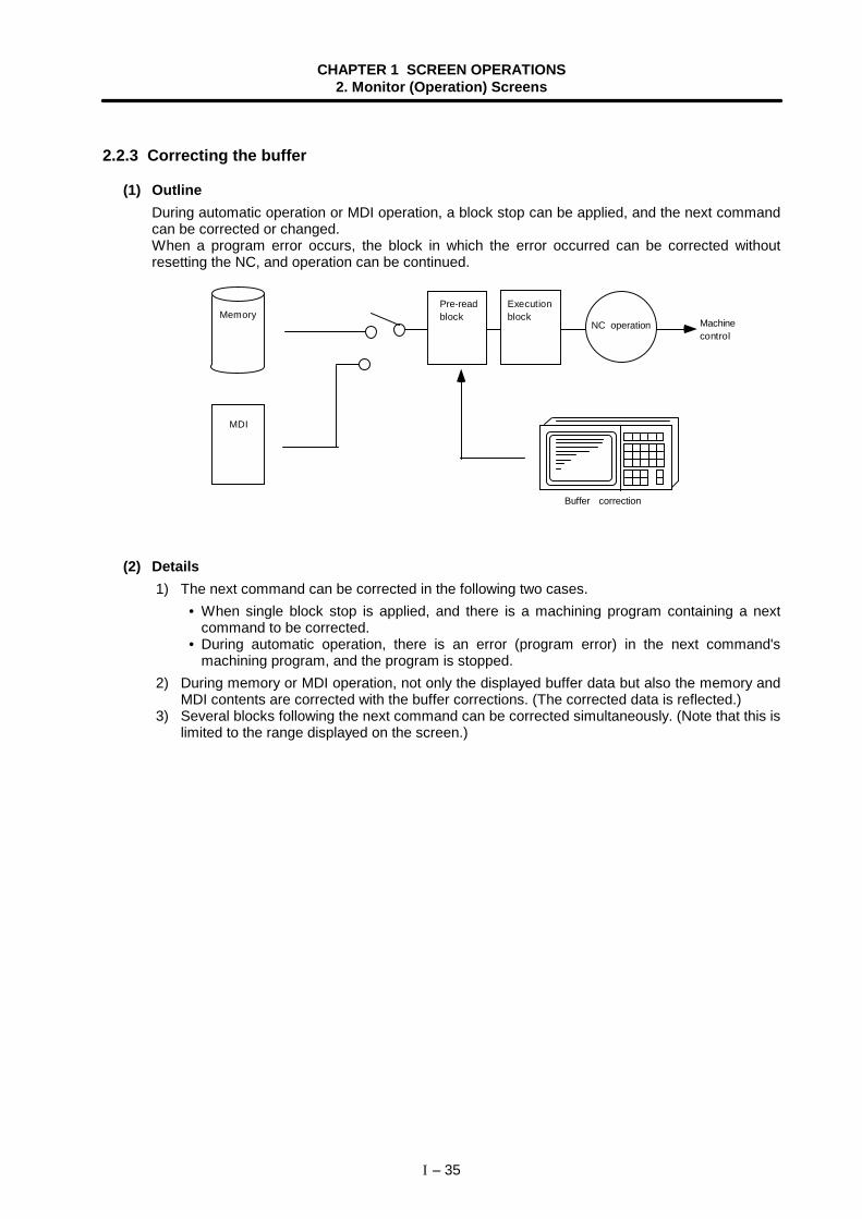
CHAPTER 1 SCREEN OPERATIONS2. Monitor (Operation) Screens
I – 35
2.2.3 Correcting the buffer
(1) OutlineDuring automatic operation or MDI operation, a block stop can be applied, and the next commandcan be corrected or changed.When a program error occurs, the block in which the error occurred can be corrected withoutresetting the NC, and operation can be continued.
Memory
MDI
Pre-readblock
Executionblock
NC operation Machinecontrol
Buffer correction
(2) Details 1) The next command can be corrected in the following two cases.
• When single block stop is applied, and there is a machining program containing a nextcommand to be corrected.
• During automatic operation, there is an error (program error) in the next command'smachining program, and the program is stopped.
2) During memory or MDI operation, not only the displayed buffer data but also the memory andMDI contents are corrected with the buffer corrections. (The corrected data is reflected.)
3) Several blocks following the next command can be corrected simultaneously. (Note that this islimited to the range displayed on the screen.)
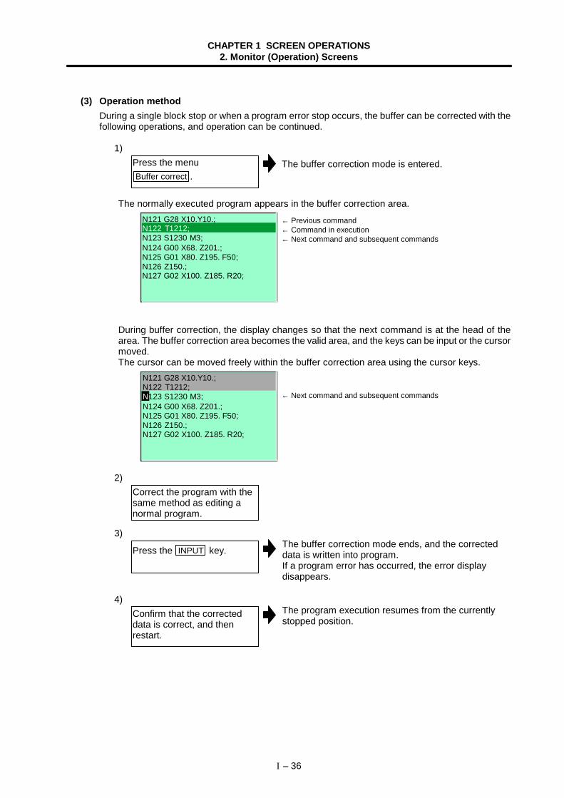
CHAPTER 1 SCREEN OPERATIONS2. Monitor (Operation) Screens
I – 36
(3) Operation methodDuring a single block stop or when a program error stop occurs, the buffer can be corrected with thefollowing operations, and operation can be continued.
1)
The normally executed program appears in the buffer correction area.
N121 G28 X10.Y10.;N122 T1212;N123 S1230 M3;N124 G00 X68. Z201.;N125 G01 X80. Z195. F50;N126 Z150.;N127 G02 X100. Z185. R20;
During buffer correction, the display changes so that the next command is at the head of thearea. The buffer correction area becomes the valid area, and the keys can be input or the cursormoved.The cursor can be moved freely within the buffer correction area using the cursor keys.
N121 G28 X10.Y10.;N122 T1212;
N124 G00 X68. Z201.;N125 G01 X80. Z195. F50;N126 Z150.;N127 G02 X100. Z185. R20;
N123 S1230 M3;
2)
3)The buffer correction mode ends, and the correcteddata is written into program.If a program error has occurred, the error displaydisappears.
4)The program execution resumes from the currentlystopped position.
Press the menuBuffer correct .
Correct the program with thesame method as editing anormal program.
Press the INPUT key.
Confirm that the correcteddata is correct, and thenrestart.
← Previous command← Command in execution← Next command and subsequent commands
← Next command and subsequent commands
The buffer correction mode is entered.
CHAPTER 1 SCREEN OPERATIONS2. Monitor (Operation) Screens
I – 37
(4) Notes Starting and ending buffer corrections
1) If automatic operation is started or there is no next command data, the buffer correctionmode is not entered even if the menu key is pressed.
2) If an "Pre-read block error" occurs and the buffer correction mode is entered, the block inwhich the error occurred displays at the head of the area.
3) To stop or to cancel the buffer corrections, press the Buffer correct key again, or press the
key.
4) If another menu key, etc., is pressed before pressing the INPUT key, the corrected buffercontents return to the original data.
5) If another screen is changed to or if the NC is reset during buffer correction, the buffercorrection is canceled. In this case, the corrected contents are not saved, and the buffercorrection mode ends.
Display data during buffer correction1) The key operations used for corrections in the buffer correction mode are the same as the
operations when editing a program. However, blocks not displayed in the buffer correctionarea cannot be displayed or edited.
2) The number of characters that can be input at once is the total of the number of charactersincremented (or decremented) through the buffer correction and the number of charactersin the other blocks displayed in the correction area. The number is a max. 234 characters(39 characters × six lines). Therefore, if adding data, when there is no open area left in thecorrection area, further characters cannot be input.By pressing the INPUT key again at this time, the program is redisplayed for each block.Enter the buffer correction mode again, and then add the data.
Operations during buffer correction1) If there is no ";" (EOB) at the data in the last block corrected when the INPUT key is
pressed, it is added automatically.2) When the buffer correction mode is entered, the last block displayed in the buffer correction
area may not fit in if the block is long, etc.To correct this type of block, take care to the following points.(a) If a ";" (EOB) is added to the end of the displayed data, the section following the
incomplete display becomes another block. If ";" (EOB) is not added, the followingsection stays the same, and is handled as the continuation of the displayed section.
(b) If one block is deleted by pressing the C·B ESC key, the block is deleted up to thesection following the incomplete display (up to the ";").
3) Operation cannot be started during buffer correction. An alarm occurs.
2.2.4 Changing the display axis
If many axes are being used and all axes cannot be displayed on the counter at once, the menu keyNext axis can be pressed to change the displayed axes and display the remaining axes.
Refer to "1.5.4 Changing the display axis" for details.
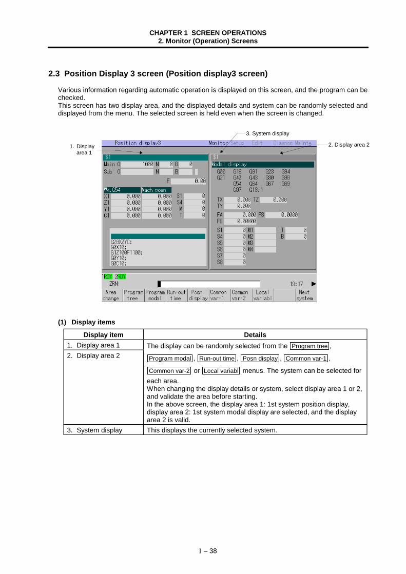
CHAPTER 1 SCREEN OPERATIONS2. Monitor (Operation) Screens
I – 38
2.3 Position Display 3 screen (Position display3 screen)
Various information regarding automatic operation is displayed on this screen, and the program can bechecked.This screen has two display area, and the displayed details and system can be randomly selected anddisplayed from the menu. The selected screen is held even when the screen is changed.
(1) Display items
Display item Details1. Display area 12. Display area 2
The display can be randomly selected from the Program tree ,
Program modal , Run-out time , Posn display , Common var-1 ,
Common var-2 or Local variabl menus. The system can be selected foreach area.When changing the display details or system, select display area 1 or 2,and validate the area before starting.In the above screen, the display area 1: 1st system position display,display area 2: 1st system modal display are selected, and the displayarea 2 is valid.
3. System display This displays the currently selected system.
2. Display area 21. Displayarea 1
3. System display
CHAPTER 1 SCREEN OPERATIONS2. Monitor (Operation) Screens
I – 39
(2) Menus
Menu Details Type ReferenceArea
changeThis changes between display area 1 and display area 2. C 1.5.2 Changing
the valid areaProgram
tree
Programmodal
Run-outtime
Posndisplay
Commonvar-1
Commonvar-2
Localvariabl
The display area 1 and 2 display details are selected fromthese menus.
C
(3) Display area 1and 2 details
Counter1 type
Counter2 type
The counter type displayed when Posn display is selectedis selected from the menu.The display details and selection method are the same asthe Position display1 screen and Position display2 screen.
C
2.1.1 Changingthe counterdisplay
Nextsystem
This appears when there are two or more valid systems.The system No. will be incremented by one each time thismenu is pressed.(Note) If the system No. to be displayed next exceeds the
number of valid systems, the information for the 1stsystem will appear.
C
1.5.6 Changingthe display system
VariablNo.
A random variable No. can be selected whenCommon var-1 , Common var-2 or Local variabl is selected.
When the variable No. is set and the INPUT key is pressed,the variables appear with that variable No. at the head.The cursor moves to the details of that variable No.
A
2.6.2 Settingcommon variables2.7.1 Displayinglocal variables
Displaylevel
The display level can be selected when Local variabl isselected.When the level (0 to 4) to be displayed is set and the INPUTkey is pressed, the local variables appear from the head ofthat level.The cursor appears at the head variable No.
A
2.7.1 Displayinglocal variables
Abs/Inc
The absolute value/incremental value setting mode can bechanged when Common var-1 or Common var-2 isselected.The "Abs/Inc" on the screen changes from incremental toabsolute, or from absolute to incremental.
C
1.5.3 Changingthe absolutevalue/incrementalvalue setting
Timesetting
The cumulative time can be set when Run-out time isselected.
A2.3.2 Setting thecumulative time
(Note) The Common var-2 menu cannot be selected when type C (450 sets) or type D (900 sets) isselected for the number of common variable sets.
CHAPTER 1 SCREEN OPERATIONS2. Monitor (Operation) Screens
I – 40
(3) Display area 1 and 2 details
Menu Display details Details
Programtree
This displays the main program,subprogram, MDI interrupt and usermacro call nesting structure.
O : Program No. N : Sequence No. B : Block No. L : Remaining number of
subprogram repetitionsMode : Operation mode1 to 8 : Called subprogram, user
macro call and MDIinterrupt
This displays each modal state.G01...G98
G97...G13.1
Status of currentlyexecuted G commandmodal
TX:TZ:T :
The X axis, Z axis toollength and wear offsetamount for the toolbeing used aredisplayed.T indicates the toollength or wear offsetamount for the axisselected from theadditional axes.
FA: The programcommandasynchronous feedspeed modal valuecurrently beingexecuted is displayed.(mm/min)
FS: The programcommand synchronousfeed speed modalvalue currently beingexecuted is displayed.(mm/rev)
FE: The thread leadcommandsynchronous feedspeed modal valuecurrently beingexecuted is displayed.(mm/rev)
Programmodal
(Note) Fixed cycle programsWhen a Fixed cycle command isexecuted, the G command in theFixed cycle subprogram does notinfluence the G modal in theoriginal program that was called.
S1 to S6M1 to M4TB
Program commandmodal value of eachcurrently executedcommandS commandM commandT command2nd miscellaneousfunction (B) command
CHAPTER 1 SCREEN OPERATIONS2. Monitor (Operation) Screens
I – 41
Menu Display details Details
Run-outtime
This displays the total cumulative timein each NC operation state. Refer to"2.3.2 Setting the cumulative time" fordetails on setting each data.
Date : Current dateTime : Current timePower ON : Total time from NC power
ON to OFFAuto oper:
Total cumulative time of eachmachining time in memory modefrom when automatic start button ispressed to M02/M30 or to whenreset button is pressed.
Auto strt:Total cumulative time of automaticstart in memory mode from whenautomatic start button is pressed tofeed hold stop, block stop or to whenreset button is pressed.
Ext time:This differs depending on the userPLC. Refer to the instruction manualissued by the machinemanufacturer.
Posndisplay
Upper line:This displays the currently executedprogram No., sequence No. and blockNo.
Middle line:The counter is displayed.The details displayed in the counter 1and 2 can be selected from the menuCounter 1 type and Counter 2 type
submenus.Refer to "2.1.1 Changing the counterdisplay" for details.
Lower line:This displays the program currentlybeing executed in the buffer. Note thatthe buffer must be corrected on thePosition display2 screen.
CHAPTER 1 SCREEN OPERATIONS2. Monitor (Operation) Screens
I – 42
Menu Display details DetailsCommon
var-1This displays or sets the details of thecommon variables 1 (variablescommon to systems). When there is acommon variable command in themachining program, the set variable(comment) appears when that block isexecuted.Refer to "2.6.2 Setting commonvariables" for details on setting.
Commonvar-2
This displays or sets the details of thecommon variables 2 (variablesindependent each system). When thereis a common variable command in themachining program, the set variableappears when that block is executed.Refer to "2.6.2 Setting commonvariables" for details on setting.
Localvariabl
This displays the details of the localvariables.There are 1 to 32 local variables foreach subprogram call level in the usermacros. For each level, 32 localvariable data items are displayed.These are configured from level 0 tolevel 4 in page order. If a blockcontaining a variable command isexecuted, the details are rewritten.Refer to "2.7.1 Displaying localvariables" for details on the display.
CHAPTER 1 SCREEN OPERATIONS2. Monitor (Operation) Screens
I – 43
2.3.1 Changing the counter display
The details displayed in the counter 1 and counter 2 displays can be randomly selected from the followingtypes.
• Currnt posn • Work co posn • Machine posn • Program posn • Remain command • Manual int amt • Er comp amnt
Refer to "2.1 Position Display 1 screen" for details on each item and the setting methods.
2.3.2 Setting the cumulative time
Each data for the cumulative time display is set.
(1) Operation method
1)
2)The time setting mode is entered. The cursor appearsat the "#1 Date" position in the Run-out time display.
Run-out time display
3 Power ON 1234:59:59 4 Auto oper 1234:59:59 5 Auto strt 1234:59:59 6 Ext time1 1234:59:59 7 Ext time2 1234:59:59
2 Time 12:34:56#1 Date 1999.01.23
3)"1999.07.03" appears at "#1 Date", and the cursormoves to "#2 Time".
Run-out time display
3 Power ON 1234:59:59 4 Auto oper 1234:59:59 5 Auto strt 1234:59:59 6 Ext time1 1234:59:59 7 Ext time2 1234:59:59
#1 Date 1999.07.03 2 Time 12:34:56
4)When the "#7 Ext time2" setting is finished, the cursordisappears, and the time setting ends.(The menu highlight returns to normal.)
(Note) If the Time setting menu is pressed again or the key is pressed during the time settingmode, the time setting is canceled.
Select display area 1, andpress the menu keyRun-out time .
Press the menu keyTime setting .
Set the current date (ex.;"1999.07.03"), and press theINPUT key.
Set the data for each item,and press the INPUT key.
The cursor appearsat "#1 Date".
The cursor appearsat "#2 Time".
The cumulative time appears in display area 1.
CHAPTER 1 SCREEN OPERATIONS2. Monitor (Operation) Screens
I – 44
2.4 Operation Search screen
In this screen, the program (program No.) to be automatically run, the program start position (sequenceNo., block No.) can be designated, and the program can be called out from the storage place such as thememory.
(1) Display items
Display item Details1. Device and directory
after searchThis displays the device and directory where the searched machiningprogram is located.
2. Search position This displays the searched program position (program No., sequenceNo., block No.).
3. Buffer display This displays the contents of the currently executed or searchedmachining program.The block being executed is highlighted.
4. Device name anddirectory settingcolumns
This displays the device name and directory designated when theprogram was selected.
5. Search positionsetting columns
This sets the program No. (O), sequence No. (N) and block No. (B) of theprogram to be searched.
6. List of directories andfiles
This displays a list of the contents contained in the device or directorydisplayed at item 4.To update the list contents, press the menu key. To scroll the list, use the
and keys.
3. Buffer display
2. Search position
4. Device nameand directorysetting columns
5. Search positionsetting columns
6. List of directoriesand files
1. Device anddirectory aftersearch
CHAPTER 1 SCREEN OPERATIONS2. Monitor (Operation) Screens
I – 45
(2) Menus
Menu Details Type ReferenceNB srch The mode changes to the sequence No. (N) and block
No. (B) input mode. A
NB srchexec
The operation search is executed based on the inputsequence No. (N) and block No. (B). When the searchis completed, these Nos. are cleared.
C
Listupdate
This updates the list contents. (The latest contents ofthe currently selected device and directory are listed.) C
Fromlist
Press this key to select the directory, file name orprogram No. from the list. The selection cursorappears in the list, and a random item can be selected.
C
2.4.1 Executingan operationsearch
Nextsystem
This appears when there are two or more validsystems.The system No. will be incremented by one each timethis menu is pressed.(Note) If the system No. to be displayed next exceeds
the number of valid systems, the informationfor the 1st system will appear.
C
1.5.6 Changingthe displaysystem
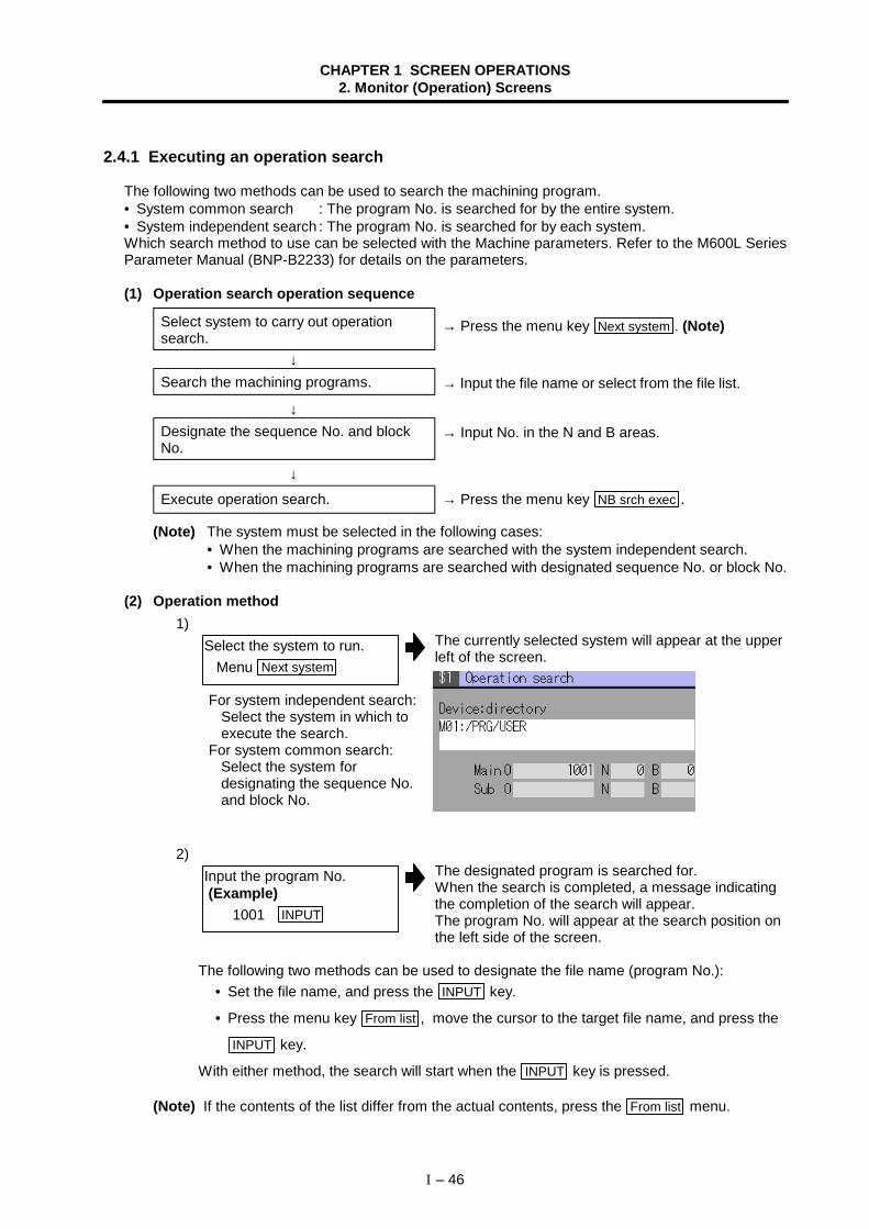
CHAPTER 1 SCREEN OPERATIONS2. Monitor (Operation) Screens
I – 46
2.4.1 Executing an operation search
The following two methods can be used to search the machining program.• System common search : The program No. is searched for by the entire system.• System independent search : The program No. is searched for by each system.Which search method to use can be selected with the Machine parameters. Refer to the M600L SeriesParameter Manual (BNP-B2233) for details on the parameters.
(1) Operation search operation sequence
Select system to carry out operationsearch.
→ Press the menu key Next system . (Note)
↓Search the machining programs. → Input the file name or select from the file list.
↓Designate the sequence No. and blockNo.
↓
→ Input No. in the N and B areas.
Execute operation search. → Press the menu key NB srch exec .
(Note) The system must be selected in the following cases:• When the machining programs are searched with the system independent search.• When the machining programs are searched with designated sequence No. or block No.
(2) Operation method1)
The currently selected system will appear at the upperleft of the screen.
2)The designated program is searched for.When the search is completed, a message indicatingthe completion of the search will appear.The program No. will appear at the search position onthe left side of the screen.
The following two methods can be used to designate the file name (program No.):• Set the file name, and press the INPUT key.
• Press the menu key From list , move the cursor to the target file name, and press the
INPUT key.
With either method, the search will start when the INPUT key is pressed.
(Note) If the contents of the list differ from the actual contents, press the From list menu.
Select the system to run. Menu Next system
For system independent search:Select the system in which toexecute the search.
For system common search:Select the system fordesignating the sequence No.and block No.
Input the program No. (Example) 1001 INPUT
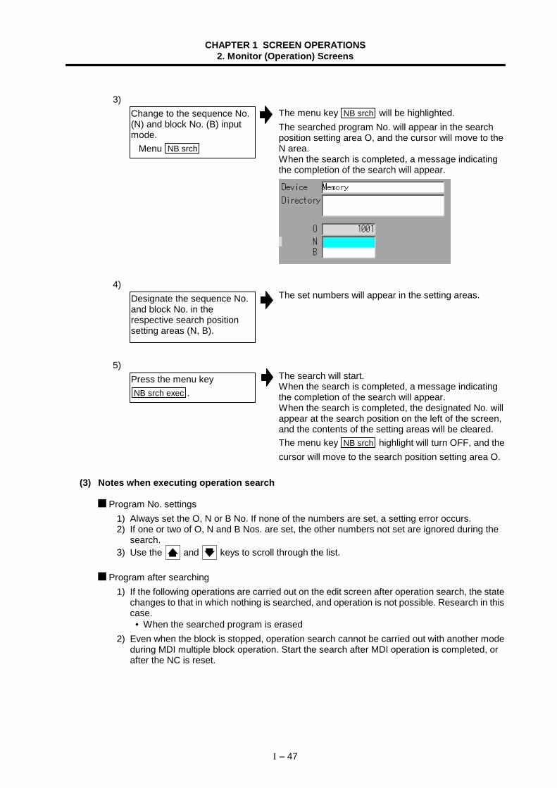
CHAPTER 1 SCREEN OPERATIONS2. Monitor (Operation) Screens
I – 47
3)The menu key NB srch will be highlighted.The searched program No. will appear in the searchposition setting area O, and the cursor will move to theN area.When the search is completed, a message indicatingthe completion of the search will appear.
4)The set numbers will appear in the setting areas.
5)The search will start.When the search is completed, a message indicatingthe completion of the search will appear.When the search is completed, the designated No. willappear at the search position on the left of the screen,and the contents of the setting areas will be cleared.The menu key NB srch highlight will turn OFF, and thecursor will move to the search position setting area O.
(3) Notes when executing operation search
Program No. settings1) Always set the O, N or B No. If none of the numbers are set, a setting error occurs.2) If one or two of O, N and B Nos. are set, the other numbers not set are ignored during the
search.3) Use the and keys to scroll through the list.
Program after searching1) If the following operations are carried out on the edit screen after operation search, the state
changes to that in which nothing is searched, and operation is not possible. Research in thiscase.
• When the searched program is erased2) Even when the block is stopped, operation search cannot be carried out with another mode
during MDI multiple block operation. Start the search after MDI operation is completed, orafter the NC is reset.
Change to the sequence No.(N) and block No. (B) inputmode. Menu NB srch
Designate the sequence No.and block No. in therespective search positionsetting areas (N, B).
Press the menu keyNB srch exec .
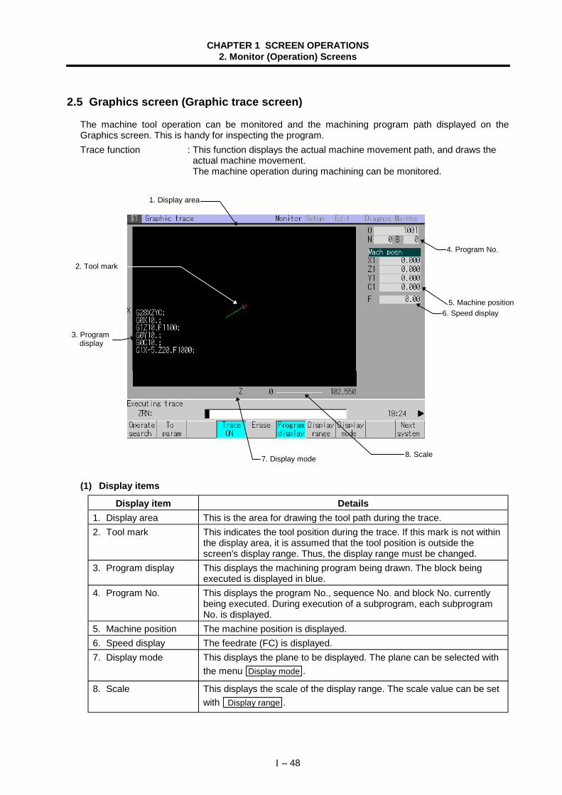
CHAPTER 1 SCREEN OPERATIONS2. Monitor (Operation) Screens
I – 48
2.5 Graphics screen (Graphic trace screen)
The machine tool operation can be monitored and the machining program path displayed on theGraphics screen. This is handy for inspecting the program.Trace function : This function displays the actual machine movement path, and draws the
actual machine movement.The machine operation during machining can be monitored.
(1) Display items
Display item Details1. Display area This is the area for drawing the tool path during the trace.2. Tool mark This indicates the tool position during the trace. If this mark is not within
the display area, it is assumed that the tool position is outside thescreen's display range. Thus, the display range must be changed.
3. Program display This displays the machining program being drawn. The block beingexecuted is displayed in blue.
4. Program No. This displays the program No., sequence No. and block No. currentlybeing executed. During execution of a subprogram, each subprogramNo. is displayed.
5. Machine position The machine position is displayed.6. Speed display The feedrate (FC) is displayed.7. Display mode This displays the plane to be displayed. The plane can be selected with
the menu Display mode .
8. Scale This displays the scale of the display range. The scale value can be setwith Display range .
3. Programdisplay
5. Machine position
1. Display area
2. Tool mark
4. Program No.
7. Display mode 8. Scale
6. Speed display
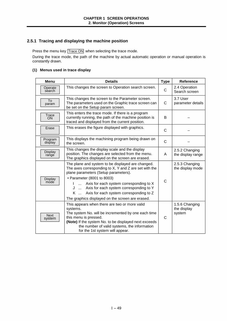
CHAPTER 1 SCREEN OPERATIONS2. Monitor (Operation) Screens
I – 49
2.5.1 Tracing and displaying the machine position
Press the menu key Trace ON when selecting the trace mode.During the trace mode, the path of the machine by actual automatic operation or manual operation isconstantly drawn.
(1) Menus used in trace display
Menu Details Type ReferenceOperatesearch
This changes the screen to Operation search screen.C
2.4 OperationSearch screen
Toparam
This changes the screen to the Parameter screen.The parameters used on the Graphic trace screen canbe set on the Setup param screen.
C3.7 Userparameter details
TraceON
This enters the trace mode. If there is a programcurrently running, the path of the machine position istraced and displayed from the current position.
B –
Erase This erases the figure displayed with graphics.C –
Programdisplay
This displays the machining program being drawn onthe screen. C –
Displayrange
This changes the display scale and the displayposition. The changes are selected from the menu.The graphics displayed on the screen are erased.
A2.5.2 Changingthe display range
Displaymode
The plane and system to be displayed are changed.The axes corresponding to X, Y and Z are set with theplane parameters (Setup parameters). • Parameter (8001 to 8003)
I ... Axis for each system corresponding to XJ ... Axis for each system corresponding to YK ... Axis for each system corresponding to Z
The graphics displayed on the screen are erased.
C
2.5.3 Changingthe display mode
Nextsystem
This appears when there are two or more validsystems.The system No. will be incremented by one each timethis menu is pressed.(Note) If the system No. to be displayed next exceeds
the number of valid systems, the informationfor the 1st system will appear.
C
1.5.6 Changingthe displaysystem
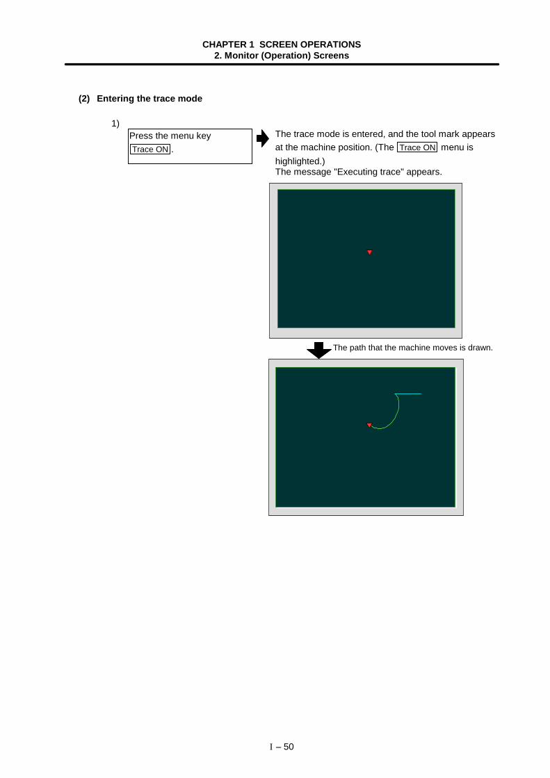
CHAPTER 1 SCREEN OPERATIONS2. Monitor (Operation) Screens
I – 50
(2) Entering the trace mode
1)The trace mode is entered, and the tool mark appearsat the machine position. (The Trace ON menu ishighlighted.)The message "Executing trace" appears.
G91 G28 XYZ;F1000;G0 X50. Y50. Z50.;G51.1 XYZ;G01 X20. Y20.Z20.;
G90 X20. Y20. Z20.;G50.1 XYZ;
G90 XYZ;
Press the menu keyTrace ON .
The path that the machine moves is drawn.
CHAPTER 1 SCREEN OPERATIONS2. Monitor (Operation) Screens
I – 51
(3) Canceling the trace mode
1)The trace mode is canceled, and the message and toolmark disappear. The Trace ON menu highlight returnsto normal.
G91 G28 XYZ;F1000;G0 X50. Y50. Z50.;G51.1 XYZ;G01 X20. Y20.Z20.;
G90 X20. Y20. Z20.;G50.1 XYZ;
G90 XYZ;
(4) Notes for tracing 1) When drawing in the trace mode, the graphic shape easily deforms as the commanded speed
increases. Note that correct shapes are not drawn when using the machine lock high-speedfunction.
Press the menu keyTrace ON during the trace
mode.
CHAPTER 1 SCREEN OPERATIONS2. Monitor (Operation) Screens
I – 52
2.5.2 Changing the display range
The scale used for drawing the graphics in trace display and the display position can be changed.
(Note) If the display range is changed, the graphics displayed up to that point are erased.
(1) Menus used for changing the display range
Menu Details Type ReferenceStd
rangeThis returns the scale to the standard scale. C –
ScaleThis sets scale to be changed with a random value.
A(4) Randomlychanging thedisplay scale 2
Centering This moves the display position so that the currentposition is in the center. C –
(2) Changing the display position
1)A white frame indicating the display range appears onthe screen, and the menu for changing the displayrange appears.
G91 G28 XYZ;F1000;G0 X50. Y50. Z50.;G51.1 XYZ;G01 X20. Y20.Z20.;
G90 X20. Y20. Z20.;G50.1 XYZ;
G90 XYZ;E xe c u t i n g t r a c e
Press the menu keyDisplay range .
CHAPTER 1 SCREEN OPERATIONS2. Monitor (Operation) Screens
I – 53
2)The displayed graphics are erased, and the cursor ( )indicating the center of the display moves according tothe key operation.
G91 G28 XYZ;F1000;G0 X50. Y50. Z50.;G51.1 XYZ;G01 X20. Y20.Z20.;
G90 X20. Y20. Z20.;G50.1 XYZ;
G90 XYZ;
3)The cursor position ( ) becomes the coordinatesystem that is the center of the screen.The drawing resumes from the current position.
G91 G28 XYZ;F1000;G0 X50. Y50. Z50.;G51.1 XYZ;G01 X20. Y20.Z20.;
G90 X20. Y20. Z20.;G50.1 XYZ;
G90 XYZ;E x e c u t i n g t r a c e
(Note 1) The amount that the center moves when the cursor shifts one space depends onthe current display scale value.
(Note 2) When displaying a solid, cursor position is not the center position of the display.This is because there is a deviation between the cursor movement amount (two-dimensional) and the actual solid movement amount (three-dimensional).
Change the figure's displayposition.Press the → , ← , ↑ and
↓ keys to adjust the positionto the display center.
Press the INPUT key.
CHAPTER 1 SCREEN OPERATIONS2. Monitor (Operation) Screens
I – 54
(3) Randomly changing the display scale 1 (Using the + and – keys)
1)A white frame indicating the display range appears onthe screen, and the menu for changing the displayrange appears.
2)The size of the white frame changes according to thekey operation.
G91 G28 XYZ;F1000;G0 X50. Y50. Z50.;G51.1 XYZ;G01 X20. Y20.Z20.;
G90 X20. Y20. Z20.;G50.1 XYZ;
G90 XYZ;
3)The current graphics display is erased, and a screenwith the new scale value appears. Drawing resumesfrom the current position.
G91 G28 XYZ;F1000;G0 X50. Y50. Z50.;G51.1 XYZ;G01 X20. Y20.Z20.;
G90 X20. Y20. Z20.;G50.1 XYZ;
G90 XYZ;
(Note 1) The scale value increments or decrements by approx. 5% each time the + key or– key is pressed.
(Note 2) The scale value can be changed within the range of 0.100 to 9999.999.
Press the menu keyDisplay range .
Change the size of the figure.Press the + or – key toadjust the scale.
Press the INPUT key.
To reduce the figure:Press the + key.The scale value increases.The frame is displayed witha dotted line.
To enlarge the figure:Press the – key.The scale value decreases.The frame is displayed witha solid line.
CHAPTER 1 SCREEN OPERATIONS2. Monitor (Operation) Screens
I – 55
(4) Randomly changing the display scale 2 (Pressing the Scale key)
1)A white frame indicating the display range appears onthe screen, and the menu for changing the displayrange appears.
2)
3)The current graphics display is erased, and a screenwith the new scale value (270) appears.Drawing resumes from the current position.
G91 G28 XYZ;F1000;G0 X50. Y50. Z50.;G51.1 XYZ;G01 X20. Y20.Z20.;
G90 X20. Y20. Z20.;G50.1 XYZ;
G90 XYZ;
Press the menu keyDisplay range .
Press the menu keyScale .
Set a random value (ex.: 270),and press the INPUT key.
The data setting cursor appears in the data input area.
To reduce the figure:Set a value larger than thecurrent value.
To enlarge the figure:Set a value smaller than thecurrent value.
CHAPTER 1 SCREEN OPERATIONS2. Monitor (Operation) Screens
I – 56
2.5.3 Changing the display mode
In the graphic display mode, which axis to be set as the vertical axis and horizontal axis when drawingcan be set using the parameter.The changed display mode is held by the Setup parameter "8091 Graphic disp mode".
The axes corresponding to X, Y and Z are set with the plane parameters (Setup parameters). Parameters
I ......... Axis for each system corresponding to XJ ........ Axis for each system corresponding to YK ........ Axis for each system corresponding to Z
(Note) When the display mode is changed, the graphics displayed up to that point are erased.
(1) Menus used for changing the display mode
Menu Details Type Reference
XYThis changes to the one plane display modeconfigured of X-Y.The X axis is displayed as the horizontal axis, and theY axis is displayed as the vertical axis.
C –
XZThis changes to the one plane display modeconfigured of X-Z.The X axis is displayed as the horizontal axis, and theZ axis is displayed as the vertical axis.
C –
YXThis changes to the one plane display modeconfigured of Y-X.The Y axis is displayed as the horizontal axis, and theX axis is displayed as the vertical axis.
C –
YZThis changes to the one plane display modeconfigured of Y-Z.The Y axis is displayed as the horizontal axis, and theZ axis is displayed as the vertical axis.
C –
ZXThis changes to the one plane display modeconfigured of Z-X.The Z axis is displayed as the horizontal axis, and theX axis is displayed as the vertical axis.
C –
ZYThis changes to the one plane display modeconfigured of Z-Y.The Z axis is displayed as the horizontal axis, and theY axis is displayed as the vertical axis.
C –
XYZ This changes to the three-dimensional display mode.A cube is displayed on the lower right of the screen. C –
CHAPTER 1 SCREEN OPERATIONS2. Monitor (Operation) Screens
I – 57
2.5.4 Changing the axis display direction
Set the direction of the horizontal axis and vertical axis when drawing the graphics.
(Note) When the display direction is changed, the graphics displayed up to that point will be erased.
When drawing the machine position on the Graphics screen, the axis drawing direction can bedesignated using the Setup parameter direct.If the direct is set to a positive scale, the path will be drawn in the reference drawing direction. If the directis set to a negative value, the path will be drawn in the direction opposite the reference drawing direction.
(1) ParameterSetup parameter Description
8093 Graphic direct <I> Drawing scale on Graphics screen for axis selected withplane selection <I>
8094 direct <J> Drawing scale on Graphics screen for axis selected withplane selection <J>
8095 direct <K> Drawing scale on Graphics screen for axis selected withplane selection <K>
(2) Reference drawing direction
(+)
(+)
(+)(+)
(+)
(−)
(-)(−)
X
Z
Y
2.5.5 Changing the drawing scale for each axis
On the Graphics screen, drawings are made using the value obtained by multiplying the currently validscale value with the drawing scale set for each axis.Thus, to change the proportion of the horizontal axis and vertical axis in the drawing, change the Setupparameter direct.Refer to "3.7.2 Setup parameter" for details on the Setup parameters.
Horizontal axis
Vertical axis
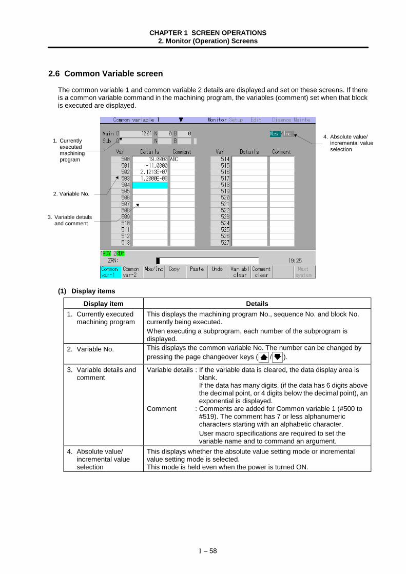
CHAPTER 1 SCREEN OPERATIONS2. Monitor (Operation) Screens
I – 58
2.6 Common Variable screen
The common variable 1 and common variable 2 details are displayed and set on these screens. If thereis a common variable command in the machining program, the variables (comment) set when that blockis executed are displayed.
(1) Display items
Display item Details1. Currently executed
machining programThis displays the machining program No., sequence No. and block No.currently being executed.When executing a subprogram, each number of the subprogram isdisplayed.
2. Variable No. This displays the common variable No. The number can be changed bypressing the page changeover keys ( / ).
3. Variable details andcomment
Variable details : If the variable data is cleared, the data display area isblank.If the data has many digits, (if the data has 6 digits abovethe decimal point, or 4 digits below the decimal point), anexponential is displayed.
Comment : Comments are added for Common variable 1 (#500 to#519). The comment has 7 or less alphanumericcharacters starting with an alphabetic character.User macro specifications are required to set thevariable name and to command an argument.
4. Absolute value/incremental valueselection
This displays whether the absolute value setting mode or incrementalvalue setting mode is selected.This mode is held even when the power is turned ON.
2. Variable No.
4. Absolute value/incremental valueselection
3. Variable detailsand comment
1. Currentlyexecutedmachiningprogram
CHAPTER 1 SCREEN OPERATIONS2. Monitor (Operation) Screens
I – 59
(2) Menus
Menu Details Type ReferenceCommon
var-1The common variables 1 are displayed.
C –
Commonvar-2
The common variables 2 are displayed.C –
Abs/Inc
This changes the setting mode to the absolute value orincremental value mode.This menu key changes the "Abs/Inc" selection fromincremental to absolute, and vice versa.
C
1.5.3 Changingthe absolutevalue/incrementalvalue setting
CopyThis copies the contents (only one line amount) of thevariable No. at the cursor position to the clipboard. Thecopied line is highlighted, and returns to normal afterpasted.
A
2.6.3 Copying/pasting commonvariables
PasteThis pastes the copied contents (only one line amount)of the variable No. at the cursor position. The copiedline can be pasted as often as necessary until a newarea is copied.
C
2.6.3 Copying/pasting commonvariables
Undo
This returns the last rewritten data to its original value.(This menu key is valid for "Data Input", "Paste" and"Undo" operations.)(Note) Return to the original value is not possible after
variable clear and comment clear operations.
C –
Variablclear
This clears the contents of the variable No. orcontinuous variable Nos. at the cursor position.(Note) The contents are not cleared to "0". The state
with no data is entered.
A
2.6.4 Erasingcommonvariables (1)
Commentclear
This clears the comment of the variable No. orcontinuous variable Nos. at the cursor position(Comment: variable Nos. 500 to 519).
A2.6.4 Erasingcommonvariables (2)
Nextsystem
This appears when there are two or more validsystems.The system No. will be incremented by one each timethis menu is pressed.(Note) If the system No. to be displayed next exceeds
the number of valid systems, the informationfor the 1st system will appear.
C
1.5.6 Changingthe displaysystem
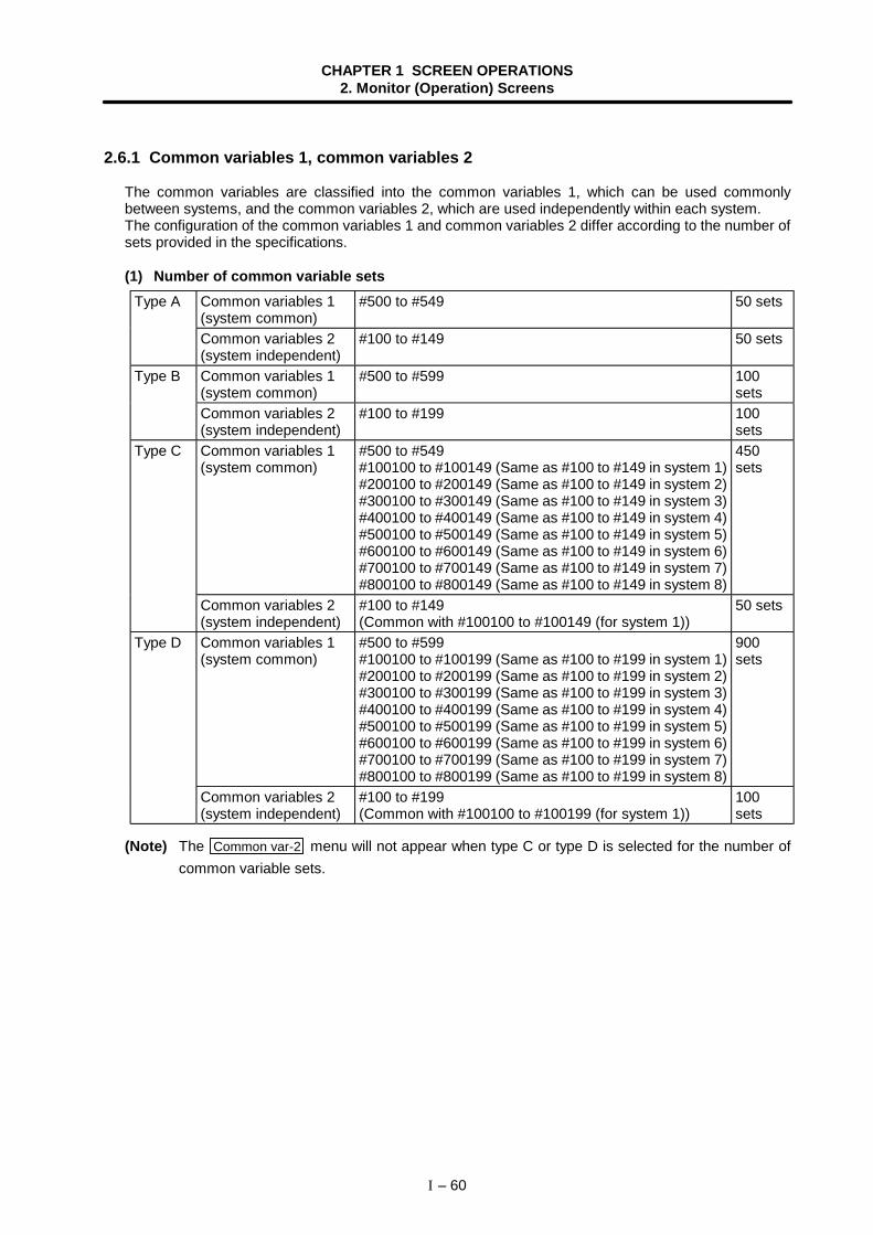
CHAPTER 1 SCREEN OPERATIONS2. Monitor (Operation) Screens
I – 60
2.6.1 Common variables 1, common variables 2
The common variables are classified into the common variables 1, which can be used commonlybetween systems, and the common variables 2, which are used independently within each system.The configuration of the common variables 1 and common variables 2 differ according to the number ofsets provided in the specifications.
(1) Number of common variable setsCommon variables 1(system common)
#500 to #549 50 setsType A
Common variables 2(system independent)
#100 to #149 50 sets
Common variables 1(system common)
#500 to #599 100sets
Type B
Common variables 2(system independent)
#100 to #199 100sets
Common variables 1(system common)
#500 to #549#100100 to #100149 (Same as #100 to #149 in system 1)#200100 to #200149 (Same as #100 to #149 in system 2)#300100 to #300149 (Same as #100 to #149 in system 3)#400100 to #400149 (Same as #100 to #149 in system 4)#500100 to #500149 (Same as #100 to #149 in system 5)#600100 to #600149 (Same as #100 to #149 in system 6)#700100 to #700149 (Same as #100 to #149 in system 7)#800100 to #800149 (Same as #100 to #149 in system 8)
450sets
Type C
Common variables 2(system independent)
#100 to #149(Common with #100100 to #100149 (for system 1))
50 sets
Common variables 1(system common)
#500 to #599#100100 to #100199 (Same as #100 to #199 in system 1)#200100 to #200199 (Same as #100 to #199 in system 2)#300100 to #300199 (Same as #100 to #199 in system 3)#400100 to #400199 (Same as #100 to #199 in system 4)#500100 to #500199 (Same as #100 to #199 in system 5)#600100 to #600199 (Same as #100 to #199 in system 6)#700100 to #700199 (Same as #100 to #199 in system 7)#800100 to #800199 (Same as #100 to #199 in system 8)
900sets
Type D
Common variables 2(system independent)
#100 to #199(Common with #100100 to #100199 (for system 1))
100sets
(Note) The Common var-2 menu will not appear when type C or type D is selected for the number ofcommon variable sets.
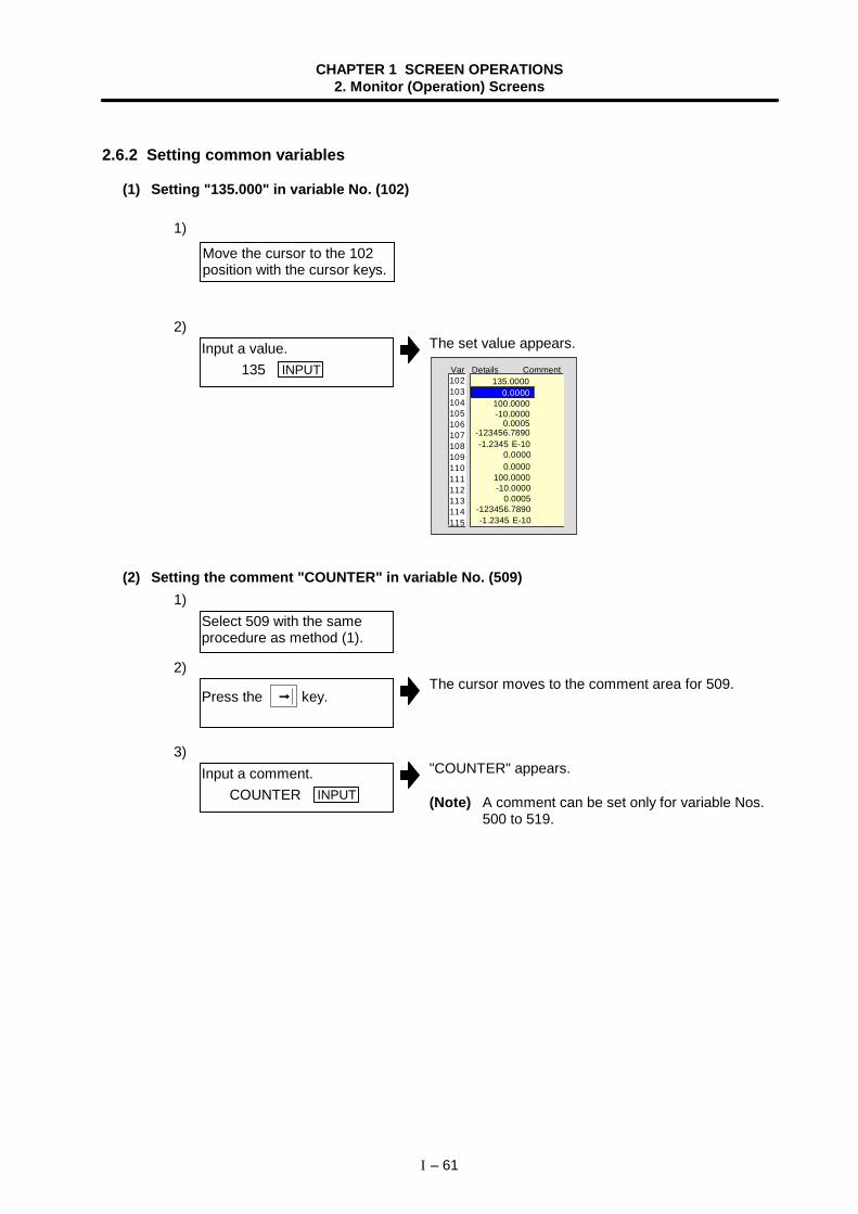
CHAPTER 1 SCREEN OPERATIONS2. Monitor (Operation) Screens
I – 61
2.6.2 Setting common variables
(1) Setting "135.000" in variable No. (102)
1)
2)The set value appears.
-1.2345 E-10 -123456.7890
-10.0000 100.0000
0.0005
-1.2345 E-10 -123456.7890
-10.0000 100.0000
0.00000.0000
0.0005
0.0000
Var Details Comment102103104105106107108109110111112113114115
135.0000
(2) Setting the comment "COUNTER" in variable No. (509)1)
2)The cursor moves to the comment area for 509.
3)"COUNTER" appears.
(Note) A comment can be set only for variable Nos.500 to 519.
Move the cursor to the 102position with the cursor keys.
Input a value. 135 INPUT
Select 509 with the sameprocedure as method (1).
Press the →→→→ key.
Input a comment. COUNTER INPUT
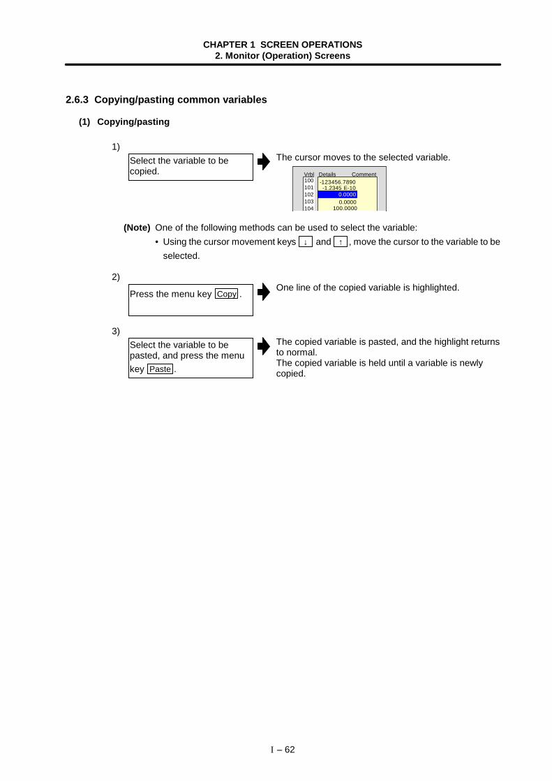
CHAPTER 1 SCREEN OPERATIONS2. Monitor (Operation) Screens
I – 62
2.6.3 Copying/pasting common variables
(1) Copying/pasting
1)The cursor moves to the selected variable.
Vrbl Details Comment
-1.2345 E-10-123456.7890
100.0000 0.0000 0.0000
100 101 102 103 104
(Note) One of the following methods can be used to select the variable:• Using the cursor movement keys ↓ and ↑ , move the cursor to the variable to be
selected.
2)One line of the copied variable is highlighted.
3)The copied variable is pasted, and the highlight returnsto normal.The copied variable is held until a variable is newlycopied.
Select the variable to becopied.
Press the menu key Copy .
Select the variable to bepasted, and press the menukey Paste .
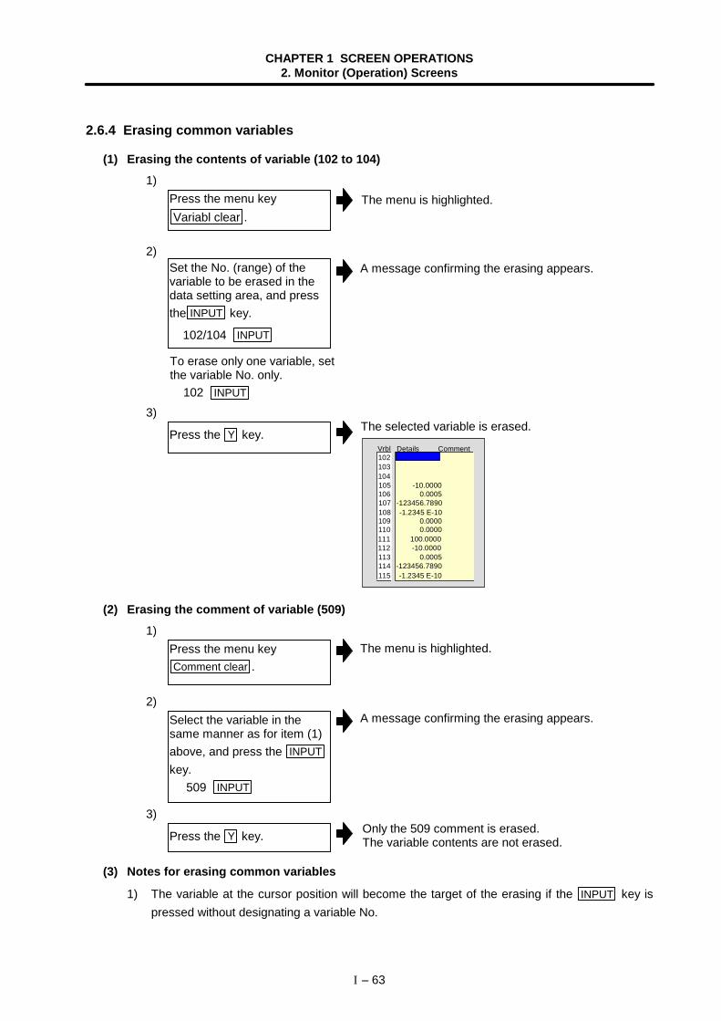
CHAPTER 1 SCREEN OPERATIONS2. Monitor (Operation) Screens
I – 63
2.6.4 Erasing common variables
(1) Erasing the contents of variable (102 to 104)1)
2)
3)The selected variable is erased.
Vrbl Details Comment
115 -1.2345 E-10114 -123456.7890
105 -10.0000 104 103
106 0.0005
108 -1.2345 E-10107 -123456.7890
112 -10.0000111 100.0000110 0.0000109 0.0000
113 0.0005
102
(2) Erasing the comment of variable (509)1)
2)
3)
(3) Notes for erasing common variables
1) The variable at the cursor position will become the target of the erasing if the INPUT key ispressed without designating a variable No.
Press the menu keyVariabl clear .
Set the No. (range) of thevariable to be erased in thedata setting area, and pressthe INPUT key.
102/104 INPUT
Press the Y key.
Press the menu keyComment clear .
Select the variable in thesame manner as for item (1)above, and press the INPUTkey. 509 INPUT
Press the Y key.
The menu is highlighted.
The menu is highlighted.
A message confirming the erasing appears.
Only the 509 comment is erased.The variable contents are not erased.
A message confirming the erasing appears.
To erase only one variable, setthe variable No. only. 102 INPUT
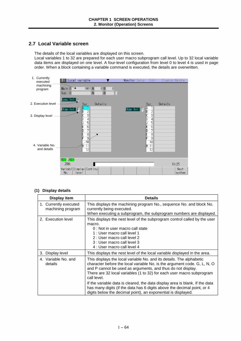
CHAPTER 1 SCREEN OPERATIONS2. Monitor (Operation) Screens
I – 64
2.7 Local Variable screen
The details of the local variables are displayed on this screen.Local variables 1 to 32 are prepared for each user macro subprogram call level. Up to 32 local variabledata items are displayed on one level. A four-level configuration from level 0 to level 4 is used in pageorder. When a block containing a variable command is executed, the details are overwritten.
(1) Display details
Display item Details1. Currently executed
machining programThis displays the machining program No., sequence No. and block No.currently being executed.When executing a subprogram, the subprogram numbers are displayed.
2. Execution level This displays the nest level of the subprogram control called by the usermacro.
0 : Not in user macro call state1 : User macro call level 12 : User macro call level 23 : User macro call level 34 : User macro call level 4
3. Display level This displays the nest level of the local variable displayed in the area.4. Variable No. and
detailsThis displays the local variable No. and its details. The alphabeticcharacter before the local variable No. is the argument code. G, L, N, Oand P cannot be used as arguments, and thus do not display.There are 32 local variables (1 to 32) for each user macro subprogramcall level.If the variable data is cleared, the data display area is blank. If the datahas many digits (if the data has 6 digits above the decimal point, or 4digits below the decimal point), an exponential is displayed.
2. Execution level
4. Variable No.and details
1. Currentlyexecutedmachiningprogram
3. Display level
CHAPTER 1 SCREEN OPERATIONS2. Monitor (Operation) Screens
I – 65
(2) Menus
Menu Details Type Reference
VariablNo.
A random variable No. can be selected in the validarea.Set the variable No., and press the INPUT key. Thevariable with that number at the head displays.The cursor moves to the details for that variable No.
A
2.7.1 (1)Displayingrandom variables
Displaylevel
The display level can be selected in the valid area. Setthe level (0 to 4) to be displayed, and press the
INPUT key. The local variables appear from the headof that level.The cursor moves to the variable No. at the head.
A
2.7.1 (2)Changing thedisplay level
Continu
This displays the variables following the variablesdisplayed in the valid area (area containing cursor) inthe area with no cursor currently displayed.• When cursor is in left area :
The following variable Nos. are displayed in theright area.
• When cursor is in right area :The variables with numbers smaller than thevariables displayed in the right area are displayedin the left area.
C –
Nextsystem
This appears when there are two or more validsystems.The system No. will be incremented by one each timethis menu is pressed.(Note) If the system No. to be displayed next exceeds
the number of valid systems, the informationfor the 1st system will appear.
C
1.5.6 Changingthe displaysystem
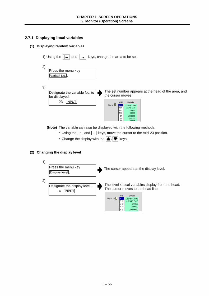
CHAPTER 1 SCREEN OPERATIONS2. Monitor (Operation) Screens
I – 66
2.7.1 Displaying local variables
(1) Displaying random variables
1) Using the ←←←← and →→→→ keys, change the area to be set.
2)
3)The set number appears at the head of the area, andthe cursor moves.
Disp lvl 4X24 -1.2345 E-10
28 -10.0000 27 100.0000Z26 0.0000
29 0 0005
Vrbl Details
Y25 0.0000
W23 -123456.7890
(Note) The variable can also be displayed with the following methods.• Using the ↑ and ↓ keys, move the cursor to the Vrbl 23 position.
• Change the display with the / keys.
(2) Changing the display level
1)
The cursor appears at the display level.
2)The level 4 local variables display from the head.The cursor moves to the head line.
Disp lvl 4
B 2 -1.2345 E-10
J 5 100.0000I 4 0.0000
Vrbl Details
C 3 0.0000
A 1 -123456.7890
Press the menu keyVariabl No. .
Designate the variable No. tobe displayed. 23 INPUT
Press the menu keyDisplay level .
Designate the display level. 4 INPUT
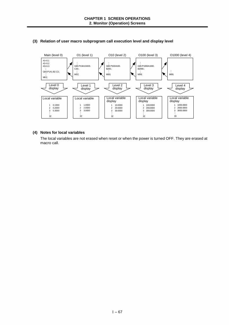
CHAPTER 1 SCREEN OPERATIONS2. Monitor (Operation) Screens
I – 67
(3) Relation of user macro subprogram call execution level and display level
#1=0.1#2=0.2#3=0.3
G65 P1A1.B2.C3.;
M02;
1 0.1000 2 0.2000 3 0.3000
32
M99;
1 1000.0000 2 2000.0000 3 3000.0000
33
G65 P1000A1000.B2000.;
M99;
1 100.0000 2 200.0000 3 300.0000
32
G65 P100A100.B200.;
M99;
1 10.0000 2 20.0000 3 30.0000
32
G65 P10A10.B20.C30.;
M02;
1 1.0000 2 2.0000 3 3.0000
32
:
:
:
:
:
:
:
: :
: : : : :
(4) Notes for local variablesThe local variables are not erased when reset or when the power is turned OFF. They are erased atmacro call.
Main (level 0) O1 (level 1) O10 (level 2) O100 (level 3) O1000 (level 4)
Level 0display
Local variable
Level 1display
Level 2display
Level 3display
Level 4display
Local variable Local variabledisplay
Local variabledisplay
Local variabledisplay
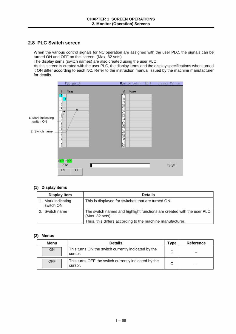
CHAPTER 1 SCREEN OPERATIONS2. Monitor (Operation) Screens
I – 68
2.8 PLC Switch screen
When the various control signals for NC operation are assigned with the user PLC, the signals can beturned ON and OFF on this screen. (Max. 32 sets)The display items (switch names) are also created using the user PLC.As this screen is created with the user PLC, the display items and the display specifications when turnedit ON differ according to each NC. Refer to the instruction manual issued by the machine manufacturerfor details.
(1) Display items
Display item Details1. Mark indicating
switch ONThis is displayed for switches that are turned ON.
2. Switch name The switch names and highlight functions are created with the user PLC.(Max. 32 sets).Thus, this differs according to the machine manufacturer.
(2) Menus
Menu Details Type ReferenceON This turns ON the switch currently indicated by the
cursor. C –
OFF This turns OFF the switch currently indicated by thecursor. C –
1. Mark indicatingswitch ON
2. Switch name
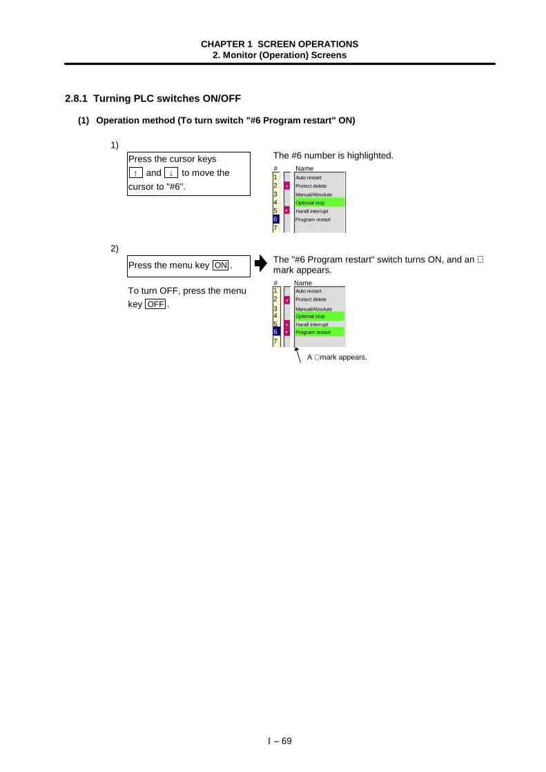
CHAPTER 1 SCREEN OPERATIONS2. Monitor (Operation) Screens
I – 69
2.8.1 Turning PLC switches ON/OFF
(1) Operation method (To turn switch "#6 Program restart" ON)
1)The #6 number is highlighted.# Name
5 Handl interrupt
1 Auto restart 2 Protect delete
3 Manual/Absolute 4 Optional stop
6 Program restart
7
*
*
2)The "#6 Program restart" switch turns ON, and an ∗mark appears.# Name
5 Handl interrupt
1 Auto restart 2 Protect delete
3 Manual/Absolute 4 Optional stop
78
*
** 6 Program restart
Press the cursor keys ↑ and ↓ to move the
cursor to "#6".
Press the menu key ON .
A ∗ mark appears.
To turn OFF, press the menukey OFF .
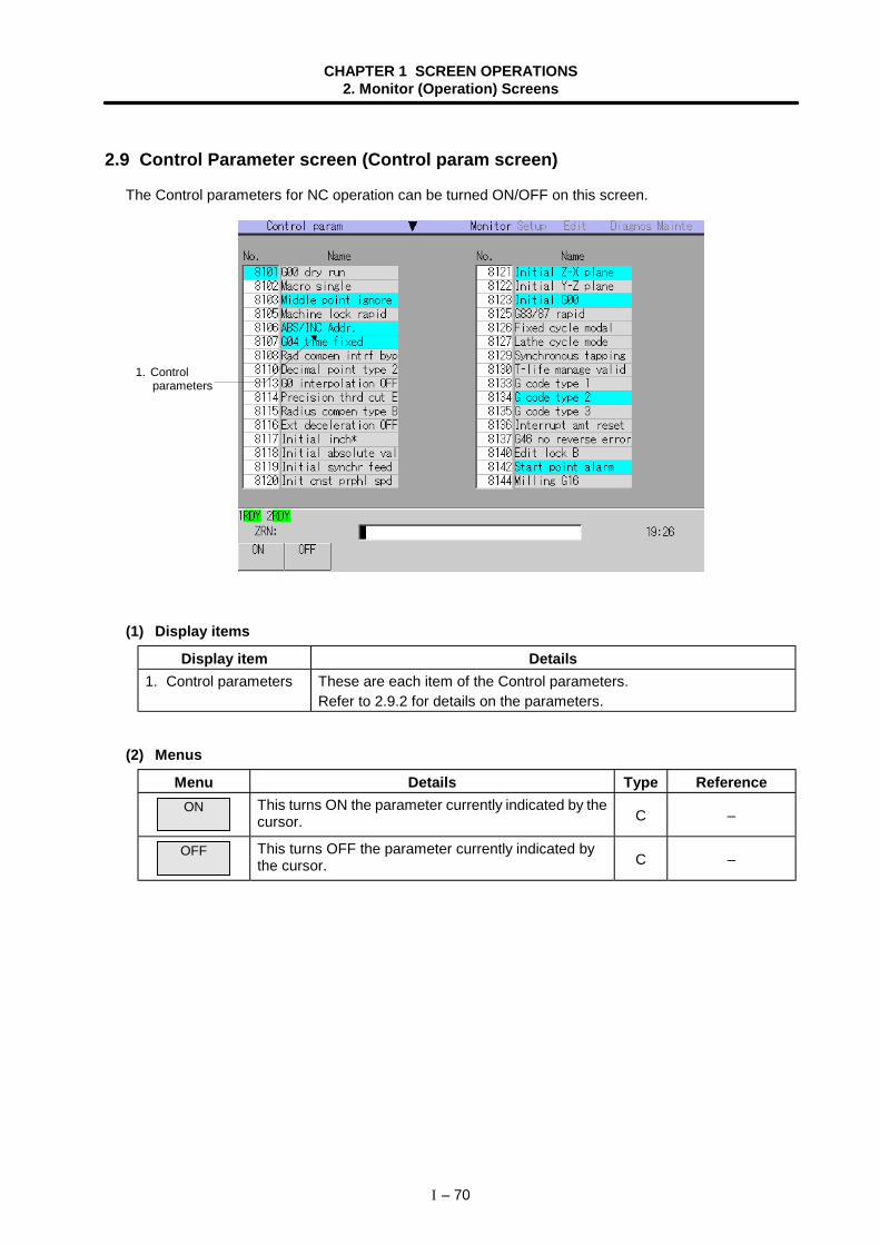
CHAPTER 1 SCREEN OPERATIONS2. Monitor (Operation) Screens
I – 70
2.9 Control Parameter screen (Control param screen)
The Control parameters for NC operation can be turned ON/OFF on this screen.
(1) Display items
Display item Details1. Control parameters These are each item of the Control parameters.
Refer to 2.9.2 for details on the parameters.
(2) Menus
Menu Details Type ReferenceON This turns ON the parameter currently indicated by the
cursor. C –
OFF This turns OFF the parameter currently indicated bythe cursor. C –
1. Control parameters
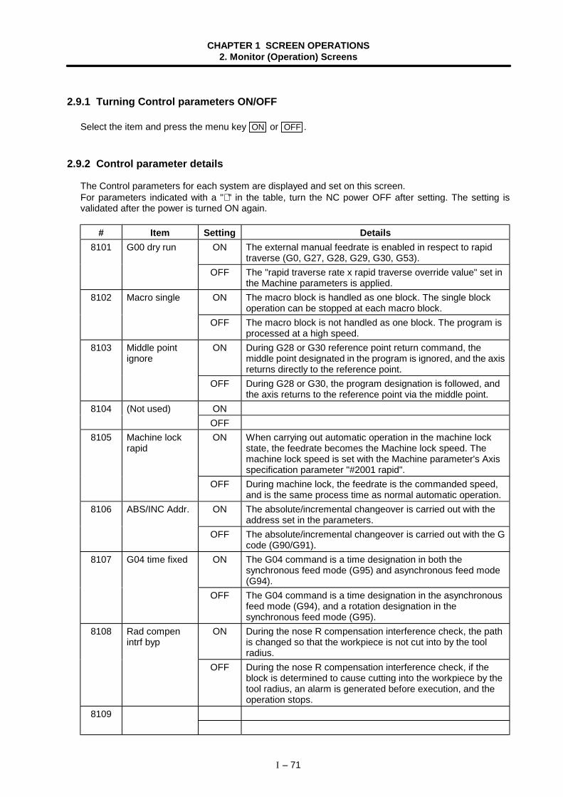
CHAPTER 1 SCREEN OPERATIONS2. Monitor (Operation) Screens
I – 71
2.9.1 Turning Control parameters ON/OFF
Select the item and press the menu key ON or OFF .
2.9.2 Control parameter details
The Control parameters for each system are displayed and set on this screen.For parameters indicated with a "∗ " in the table, turn the NC power OFF after setting. The setting isvalidated after the power is turned ON again.
# Item Setting Details8101 G00 dry run ON The external manual feedrate is enabled in respect to rapid
traverse (G0, G27, G28, G29, G30, G53).OFF The "rapid traverse rate x rapid traverse override value" set in
the Machine parameters is applied.8102 Macro single ON The macro block is handled as one block. The single block
operation can be stopped at each macro block.OFF The macro block is not handled as one block. The program is
processed at a high speed.8103 Middle point
ignoreON During G28 or G30 reference point return command, the
middle point designated in the program is ignored, and the axisreturns directly to the reference point.
OFF During G28 or G30, the program designation is followed, andthe axis returns to the reference point via the middle point.
ON8104 (Not used)OFF
8105 Machine lockrapid
ON When carrying out automatic operation in the machine lockstate, the feedrate becomes the Machine lock speed. Themachine lock speed is set with the Machine parameter's Axisspecification parameter "#2001 rapid".
OFF During machine lock, the feedrate is the commanded speed,and is the same process time as normal automatic operation.
8106 ABS/INC Addr. ON The absolute/incremental changeover is carried out with theaddress set in the parameters.
OFF The absolute/incremental changeover is carried out with the Gcode (G90/G91).
8107 G04 time fixed ON The G04 command is a time designation in both thesynchronous feed mode (G95) and asynchronous feed mode(G94).
OFF The G04 command is a time designation in the asynchronousfeed mode (G94), and a rotation designation in thesynchronous feed mode (G95).
8108 Rad compenintrf byp
ON During the nose R compensation interference check, the pathis changed so that the workpiece is not cut into by the toolradius.
OFF During the nose R compensation interference check, if theblock is determined to cause cutting into the workpiece by thetool radius, an alarm is generated before execution, and theoperation stops.
8109
CHAPTER 1 SCREEN OPERATIONS2. Monitor (Operation) Screens
I – 72
# Item Setting Details8110 Decimal point
type 2ON 1 of a position command data without a decimal point
command is controlled as 1mm (1 inch).OFF 1 of a position command data without a decimal point
command is controlled as the min. input command unit(0.01mm, 0.001mm or 0.0001mm) designated in thespecifications.
ON8111 (Not used)OFFON8112 (Not used)OFF
8113 G00interpolationOFF
ON When positioning in the G00 mode, each axis independentlymoves at the respective rapid traverse rate. The path is notlinear in respect to the end point.
OFF When positioning in the G00 mode, the axis moves at theshortest distance linearly in respect to the end point.
8114 Precision thrdcut E
ON When cutting an inch thread, address E designates theprecision lead.
OFF When cutting an inch thread, address E designates the numberof threads per inch.
8115 Radius compentype B
ON When executing start up or a cancel command during nose Rcompensation or radius compensation, the intersecting point ofthe command block and the next command block is operated.
OFF When executing start up or a cancel command during nose Rcompensation or radius compensation, the start up or cancelcommand block are not targets for the intersecting pointoperation. The offset vector in the command right angledirection is applied.
8116 ExtdecelerationOFF
ON Even if the machine interface signal's external decelerationsignal is input, it is ignored. (The machine's rapid traverse rateis not decelerated.)
OFF When the external deceleration signal is input, the machine'sfeedrate decelerates to the speed set with the machineparameters.
8117 Initial inch∗ ON The inch command mode is entered as the default when thepower is turned ON.(Inch settings are used for the parameters and compensationamounts, etc.)
OFF The metric command mode is entered as the default when thepower is turned ON.(The input setting unit is also a metric setting.)
8118 Initial absoluteval
ON The absolute value command mode is the initial state when thepower is turned ON.
OFF The incremental value command mode is the initial state whenthe power is turned ON.
8119 Initial synchrfeed
ON The synchronous feed mode is the initial state when the poweris turned ON.
OFF The asynchronous feed mode is the initial state when thepower is turned ON.
CHAPTER 1 SCREEN OPERATIONS2. Monitor (Operation) Screens
I – 73
# Item Setting Details8120 Init cnst prphl
spdON The constant surface speed control mode is the initial state
when the power is turned ON.OFF The constant surface speed control cancel mode is the initial
state when the power is turned ON.8121 Initial Z-X plane ON G18 (plane selection ZX) mode is the initial state when the
power is turned ON.OFF G17 (plane selection XY) mode or G19 (plane selection YZ)
mode is the initial state when the power is turned ON.8122 Initial Y-Z plane ON G19 (plane selection YZ) mode is the initial state when the
power is turned ON.OFF G17 (plane selection XY) mode or G18 (plane selection ZX)
mode is the initial state when the power is turned ON.8123 Initial G00 ON G00 (positioning) mode is the initial state when the power is
turned ON.OFF G01 (linear interpolation) mode is the initial state when the
power is turned ON.ON8124 (Not used)OFFON After completing each step in the deep hole drilling cycle, the
axis returns by "d" (parameter setting), and then the next stepis executed.
8125 G83/87 rapid
OFF After completing each step in the deep hole drilling cycle, theaxis returns to the R point, and then the next step is executed.
8126 Fixed cyclemodal
ON During the Fixed cycle mode, movement to the hole drillingposition follows the NC unit modal state (G0, G01).
OFF During the Fixed cycle mode, the axis is positioned to the holedrilling position with G00.
8127 Lathe cyclemode
ON If there is a block without movement in the lathe cycle (G77 toG79) mode, the same process (G77 to G79) is carried outagain. (G code type 2)
OFF If there is a block without movement in the lathe cycle (G77 toG79) mode, the lathe cycle is not executed.
ON8128 (Not used)OFFON The synchronous tapping is controlled.8129 Synchronous
tapping OFF The synchronous tapping is not controlled.8130 ON The tool life management is controlled.T-life manage
valid OFF The tool life management is not controlled.ON8131 (Not used)OFFON8132 (Not used)OFF
8133 G code type 1 Select the G code series 1 to 3.8134 G code type 2 The standard G code is type 2.8135 G code type 3 Type 3 is for additional specifications.
CHAPTER 1 SCREEN OPERATIONS2. Monitor (Operation) Screens
I – 74
# Item Setting Details8136 Interrupt amt
resetON By pressing the reset button, the amount interrupted with
manual or handle feed (when manual ABS is OFF) is cleared tozero. (The coordinate system deviated by the interruption arereturned to the original values.)
OFF Even if the reset button is pressed, the amount interrupted withmanual or handle feed (when manual ABS is OFF) is held.(The coordinate system deviated by the interruption are held.)
8137 G46 no reverseerror
ON In cases when the compensation direction reverses during G46execution, when an error occurs it will not be interpreted as anerror. Instead the process will be executed in the samecompensation direction.
OFF In cases when the compensation direction reverses during G46execution, and error will occur.
ON8138 (Not used)OFFON8139 (Not used)OFFON Editing of a label No. 8000 to 9999 machining program is
locked.8140 Edit lock B
OFF Editing of a label No. 8000 to 9999 machining program isenabled.
ON8141 (Not used)OFFON If the operation start point cannot be obtained, a program error
will occur.8142 Start point
alarmOFF The process starts after the movement block is completed.ON8143 (Not used)OFFON The default value for the plane selection is set to the G16 plane
when starting the milling mode.8144 Milling G16
OFF The default value for the plane selection is set to the G17 planewhen starting the milling mode.
ON The default value for the plane selection is set to the G19 planewhen starting the milling mode.
8145 Milling G19
OFF The default value for the plane selection is set to the G17 planewhen starting the milling mode.
ON8146 (Not used)OFFON8147 (Not used)OFFON8148 (Not used)OFFON8149 (Not used)OFFON8150 (Not used)OFF
CHAPTER 1 SCREEN OPERATIONS2. Monitor (Operation) Screens
I – 75
# Item Setting DetailsON8151 (Not used)OFFON8152 (Not used)OFFON8153 (Not used)OFFON8154 (Not used)OFFON8155 (Not used)OFFON8156 (Not used)OFFON8157 (Not used)OFFON If data without a decimal point (ex., 1) is set on the Tool offset
or Wear compensation screen, the data will be input as 1.000(1mm/inch).
8158 Tool set type 2
OFF If data without a decimal point (ex., 1) is set on the Tool offsetor Wear compensation screen, the data will be input as theminimum setting unit determined by the specifications.
ON8159 (Not used)OFF
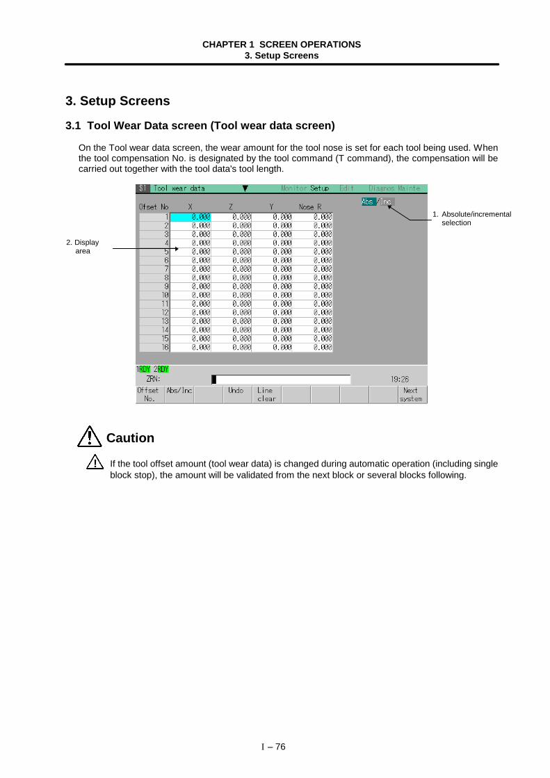
CHAPTER 1 SCREEN OPERATIONS3. Setup Screens
I – 76
3. Setup Screens
3.1 Tool Wear Data screen (Tool wear data screen)
On the Tool wear data screen, the wear amount for the tool nose is set for each tool being used. Whenthe tool compensation No. is designated by the tool command (T command), the compensation will becarried out together with the tool data's tool length.
Caution
! If the tool offset amount (tool wear data) is changed during automatic operation (including singleblock stop), the amount will be validated from the next block or several blocks following.
2. Displayarea
1. Absolute/incrementalselection
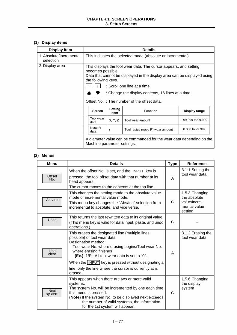
CHAPTER 1 SCREEN OPERATIONS3. Setup Screens
I – 77
(1) Display items
Display item Details1. Absolute/Incremental
selectionThis indicates the selected mode (absolute or incremental).
2. Display area This displays the tool wear data. The cursor appears, and settingbecomes possible.Data that cannot be displayed in the display area can be displayed usingthe following keys. ↑ , ↓ : Scroll one line at a time.
, : Change the display contents, 16 lines at a time.
Offset No. : The number of the offset data.
Screen Settingitem Function Display range
Tool weardata X, Y, Z Tool wear amount –99.999 to 99.999
Nose Rdata r Tool radius (nose R) wear amount 0.000 to 99.999
A diameter value can be commanded for the wear data depending on theMachine parameter settings.
(2) Menus
Menu Details Type Reference
OffsetNo.
When the offset No. is set, and the INPUT key ispressed, the tool offset data with that number at itshead appears.The cursor moves to the contents at the top line.
A
3.1.1 Setting thetool wear data
Abs/Inc
This changes the setting mode to the absolute valuemode or incremental value mode.This menu key changes the "Abs/Inc" selection fromincremental to absolute, and vice versa.
C
1.5.3 Changingthe absolutevalue/incre-mental valuesetting
UndoThis returns the last rewritten data to its original value.(This menu key is valid for data input, paste, and undooperations.)
C –
Lineclear
This erases the designated line (multiple linespossible) of tool wear data.Designation method:
Tool wear No. where erasing begins/Tool wear No.where erasing finishes
(Ex.) 1/E : All tool wear data is set to "0".When the INPUT key is pressed without designating aline, only the line where the cursor is currently at iserased.
A
3.1.2 Erasing thetool wear data
Nextsystem
This appears when there are two or more validsystems.The system No. will be incremented by one each timethis menu is pressed.(Note) If the system No. to be displayed next exceeds
the number of valid systems, the informationfor the 1st system will appear.
C
1.5.6 Changingthe displaysystem
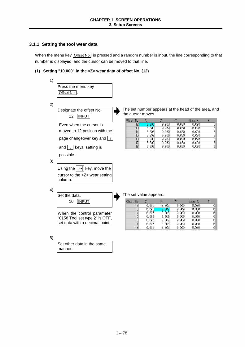
CHAPTER 1 SCREEN OPERATIONS3. Setup Screens
I – 78
3.1.1 Setting the tool wear data
When the menu key Offset No. is pressed and a random number is input, the line corresponding to thatnumber is displayed, and the cursor can be moved to that line.
(1) Setting "10.000" in the <Z> wear data of offset No. (12)
1)
2)The set number appears at the head of the area, andthe cursor moves.
3)
4)The set value appears.
5)
Press the menu keyOffset No. .
Designate the offset No. 12 INPUT
Using the →→→→ key, move thecursor to the <Z> wear settingcolumn.
Set the data. 10 INPUT
Set other data in the samemanner.
Even when the cursor ismoved to 12 position with the
page changeover key and ↑
and ↓ keys, setting is
possible.
When the control parameter"8158 Tool set type 2" is OFF,set data with a decimal point.
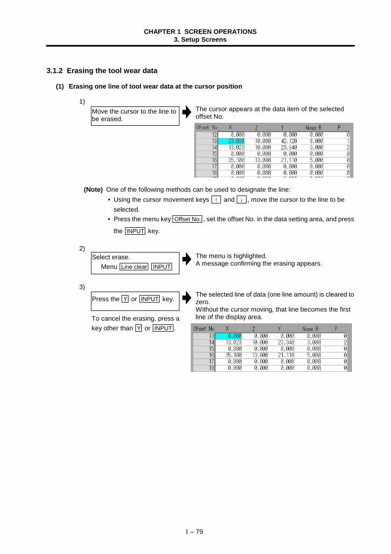
CHAPTER 1 SCREEN OPERATIONS3. Setup Screens
I – 79
3.1.2 Erasing the tool wear data
(1) Erasing one line of tool wear data at the cursor position
1)The cursor appears at the data item of the selectedoffset No.
(Note) One of the following methods can be used to designate the line: • Using the cursor movement keys ↑ and ↓ , move the cursor to the line to be
selected. • Press the menu key Offset No. , set the offset No. in the data setting area, and press
the INPUT key.
2)The menu is highlighted.A message confirming the erasing appears.
3)The selected line of data (one line amount) is cleared tozero.Without the cursor moving, that line becomes the firstline of the display area.
Move the cursor to the line tobe erased.
Select erase. Menu Line clear INPUT
Press the Y or INPUT key.
To cancel the erasing, press akey other than Y or INPUT .

CHAPTER 1 SCREEN OPERATIONS3. Setup Screens
I – 80
(2) Designating and erasing a line (multiple lines possible)
1)The menu is highlighted.
2)The range to be erased is highlighted.A message confirming the erasing appears.
3)The offset data corresponding to the designated offsetNos. is erased, and the menu highlight returns tonormal.The cursor moves to the first line of the erased range,and that line becomes the first line of the display area.
(Note) If the INPUT key is pressed without setting a offset No., the line where the cursor is atis erased.
Press the menu keyLine clear .
Set the erasing range bymarking the first and lastoffset Nos. with a "/", andpress the INPUT key.
14/17 INPUT
Press the Y or INPUT key.
To cancel the erasing, press akey other than Y and
INPUT .
CHAPTER 1 SCREEN OPERATIONS3. Setup Screens
I – 81
3.2 Tool Data screen (Tool data screen)
On the Tool data screen, the length of the tool in respect to the program base position, the radius value(R) of the tool nose installed on the tool, and the tool nose end point are set for each tool being used.When the tool compensation No. is designated by the tool command (T command), the compensationwill be carried out with the wear data.
Caution
! If the tool offset amount (tool data) is changed during automatic operation (including single blockstop), the amount will be validated from the next block or several blocks following.
2. Display area
1. Absolute/incrementalselection
4. Manual valuecommand
3. Machine positiondisplay
5. Tool lengthmeasurementdisplay
CHAPTER 1 SCREEN OPERATIONS3. Setup Screens
I – 82
(1) Display items
Display item Details1. Absolute/Incremental
selectionThis indicates the selected mode (absolute or incremental).
2. Display area This displays the tool data. The cursor appears, and setting becomespossible.Data that cannot be displayed in the display area can be displayed usingthe following keys. ↑ , ↓ : Scroll one line at a time.
, : Change the display contents, 16 lines at a time.
Offset No. : The number of the offset data.
Displayitem Setting item Description Display range
<X>, <Z>,<Y> Tool data Tool length offset amount –99999.999 to
99999.999<Nose R> Tool nose data Tool radius (nose R) 0.000 to 999.999
<P> Tool nose point Noise point No. 0 to 9
A diameter value can be commanded for the wear data depending on theMachine parameter settings.
3. Machine positiondisplay
The machine position is displayed.
4. Manual valuecommand
The command values for each M (miscellaneous function commandvalue) and T (tool command value) are displayed.Refer to "1.5.1 Setting a manual value command" for details on themanual value commands.
5. Tool lengthmeasurement display
Use this to measure the tool length. Refer to "3.2.3 Measuring the toollength" for details.
(2) Menus
Menu Details Type Reference
OffsetNo.
When the offset No. is set, and the INPUT key ispressed, the tool offset data with that number at itshead appears.The cursor moves to the contents at the top line.
A
3.2.1 Setting thetool data
Abs/IncThis changes the setting mode to the absolute valuemode or incremental value mode.This menu key changes the "Abs/Inc" selection fromincremental to absolute, and vice versa.
C
1.5.3 Changingthe absolutevalue/incrementalvalue setting
UndoThis returns the last rewritten data to its original value.(This menu key is valid for data input, paste, and undooperations.)
C –
Lineclear
This erases the designated line (multiple linespossible) of offset data.Designation method:
Offset No. where erasing begins/Offset No. whereerasing finishes
When the INPUT key is pressed without designating aline, only the line where the cursor is currently at iserased.
A
3.2.2 Erasing thetool data
CHAPTER 1 SCREEN OPERATIONS3. Setup Screens
I – 83
Menu Details Type ReferenceT-leng
measureThis changes to the tool length measurement mode. C 3.2.3 Measuring
the tool length
Nextsystem
This appears when there are two or more validsystems.The system No. will be incremented by one each timethis menu is pressed.(Note) If the system No. to be displayed next exceeds
the number of valid systems, the informationfor the 1st system will appear.
C
1.5.6 Changingthe displaysystem
3.2.1 Setting the tool data
When the menu key Offset No. is pressed and a random number is input, the line corresponding to thatnumber is displayed, and the cursor can be moved to that line.
(1) Setting "10.000" in the <Z> tool data of offset No. (12)
1)
2)The set number appears at the head of the area, andthe cursor moves.
3)
4)The set value appears.
5)
Press the menu keyOffset No. .
Designate the offset No. 12 INPUT
Using the →→→→ key, move thecursor to the <Z> tool datasetting column.
Set the data. 10 INPUT
Set other data in the samemanner.
Even when the cursor ismoved to 12 position with the
page changeover key and ↑
and ↓ keys, setting is
possible.
When the control parameter"8158 Tool set type 2" is OFF,set data with a decimal point.
CHAPTER 1 SCREEN OPERATIONS3. Setup Screens
I – 84
3.2.2 Erasing the tool data
(1) Erasing one line of tool data at the cursor position
1)The cursor appears at the data item of the selectedoffset No.
(Note) One of the following methods can be used to designate the line: • Using the cursor movement keys ↑ and ↓ , move the cursor to the line to be
selected. • Press the menu key Offset No. , set the offset No. in the data setting area, and press
the INPUT key.
2)The menu is highlighted.A message confirming the erasing appears.
3)The selected line of data (one line amount) is cleared tozero.Without the cursor moving, that line becomes the firstline of the display area.
Move the cursor to the line tobe erased.
Select erase. Menu Line clear INPUT
Press the Y or INPUT key.
To cancel the erasing, press akey other than Y or INPUT .
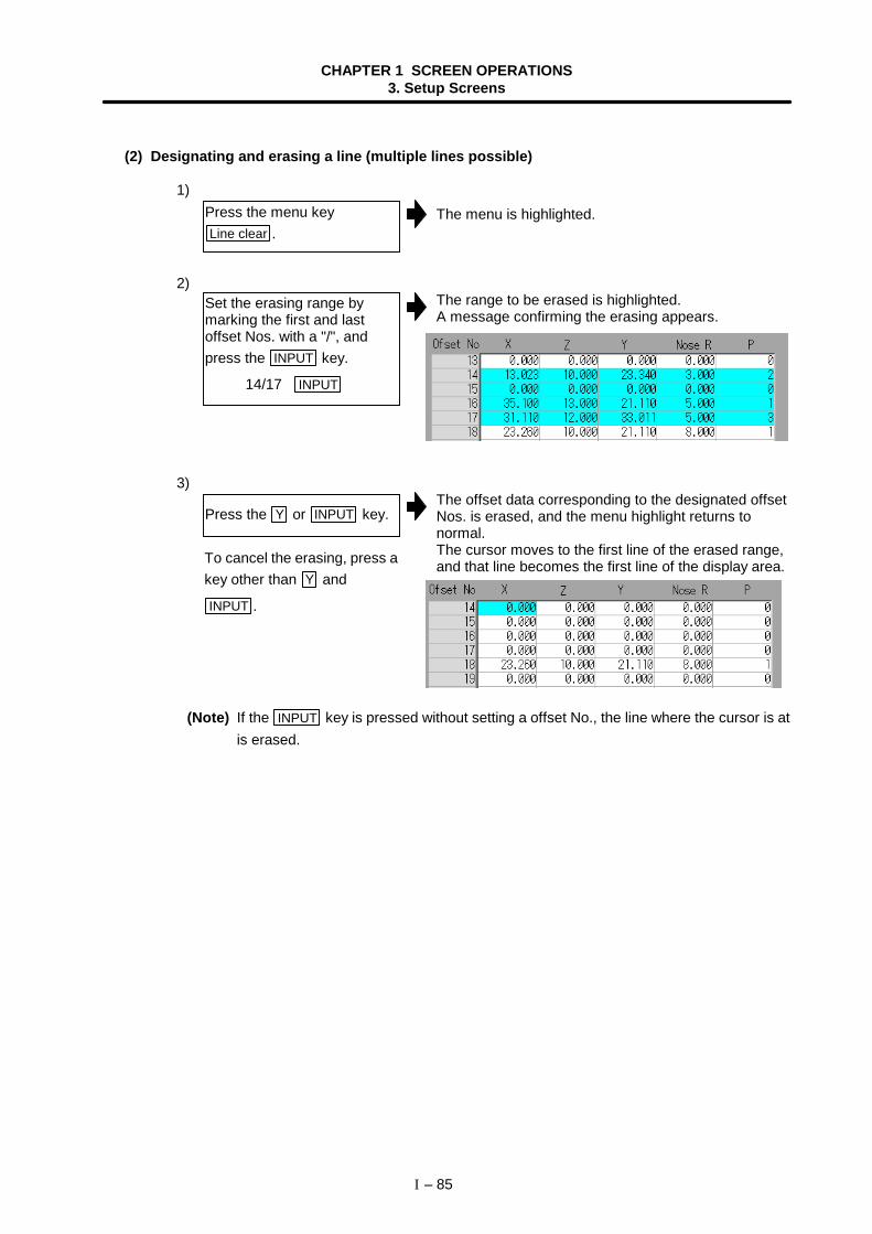
CHAPTER 1 SCREEN OPERATIONS3. Setup Screens
I – 85
(2) Designating and erasing a line (multiple lines possible)
1)The menu is highlighted.
2)The range to be erased is highlighted.A message confirming the erasing appears.
3)The offset data corresponding to the designated offsetNos. is erased, and the menu highlight returns tonormal.The cursor moves to the first line of the erased range,and that line becomes the first line of the display area.
(Note) If the INPUT key is pressed without setting a offset No., the line where the cursor is atis erased.
Press the menu keyLine clear .
Set the erasing range bymarking the first and lastoffset Nos. with a "/", andpress the INPUT key.
14/17 INPUT
Press the Y or INPUT key.
To cancel the erasing, press akey other than Y and
INPUT .
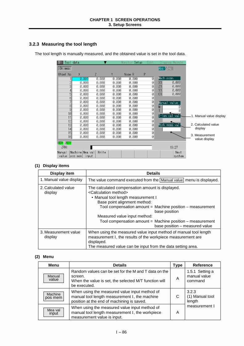
CHAPTER 1 SCREEN OPERATIONS3. Setup Screens
I – 86
3.2.3 Measuring the tool length
The tool length is manually measured, and the obtained value is set in the tool data.
(1) Display items
Display item Details1. Manual value display The value command executed from the Manual value menu is displayed.
2. Calculated valuedisplay
The calculated compensation amount is displayed.<Calculation method> • Manual tool length measurement I
Base point alignment method: Tool compensation amount = Machine position – measurement
base positionMeasured value input method: Tool compensation amount = Machine position – measurement
base position – measured value3. Measurement value
displayWhen using the measured value input method of manual tool lengthmeasurement I, the results of the workpiece measurement aredisplayed.The measured value can be input from the data setting area.
(2) Menu
Menu Details Type Reference
Manualvalue
Random values can be set for the M and T data on thescreen.When the value is set, the selected M/T function willbe executed.
A
1.5.1 Setting amanual valuecommand
Machinepos mem
When using the measured value input method ofmanual tool length measurement I, the machineposition at the end of machining is saved.
C
Mea valinput
When using the measured value input method ofmanual tool length measurement I, the workpiecemeasurement value is input.
A
3.2.3(1) Manual toollengthmeasurement I
1. Manual value display
2. Calculated valuedisplay
3. Measurementvalue display
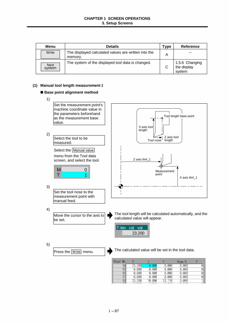
CHAPTER 1 SCREEN OPERATIONS3. Setup Screens
I – 87
Menu Details Type ReferenceWrite The displayed calculated values are written into the
memory. A –
Nextsystem
The system of the displayed tool data is changed.C
1.5.6 Changingthe displaysystem
(1) Manual tool length measurement IIII
Base point alignment method1)
2)
3)
4)The tool length will be calculated automatically, and thecalculated value will appear.
T-len cal val23.200
5)The calculated value will be set in the tool data.
Set the measurement point'smachine coordinate value inthe parameters beforehandas the measurement basevalue.
Set the tool nose to themeasurement point withmanual feed.
Move the cursor to the axis tobe set.
Press the Write menu.
Select the tool to bemeasured.
Select the Manual valuemenu from the Tool datascreen, and select the tool.
TM 0
1
Tool length base point
X axis toollength
Z axis toollengthTool nose
Z axis tlml_1
Measurementpoint
X axis tlml_1
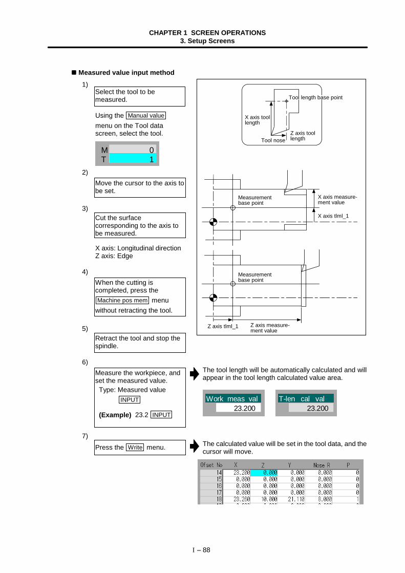
CHAPTER 1 SCREEN OPERATIONS3. Setup Screens
I – 88
Measured value input method1)
2)
3)
4)
5)
6)The tool length will be automatically calculated and willappear in the tool length calculated value area.
Work meas val23.200
T-len cal val23.200
7)The calculated value will be set in the tool data, and thecursor will move.
Move the cursor to the axis tobe set.
Cut the surfacecorresponding to the axis tobe measured.
Measure the workpiece, andset the measured value. Type: Measured value
INPUT
(Example) 23.2 INPUT
Press the Write menu.
Select the tool to bemeasured.
Using the Manual valuemenu on the Tool datascreen, select the tool.
TM 0
1
X axis: Longitudinal directionZ axis: Edge
Retract the tool and stop thespindle.
When the cutting iscompleted, press theMachine pos mem menu
without retracting the tool.
Tool length base point
X axis toollength
Z axis toollengthTool nose
X axis measure-ment value
Measurementbase point
Measurementbase point
Z axis measure-ment value
Z axis tlml_1
X axis tlml_1
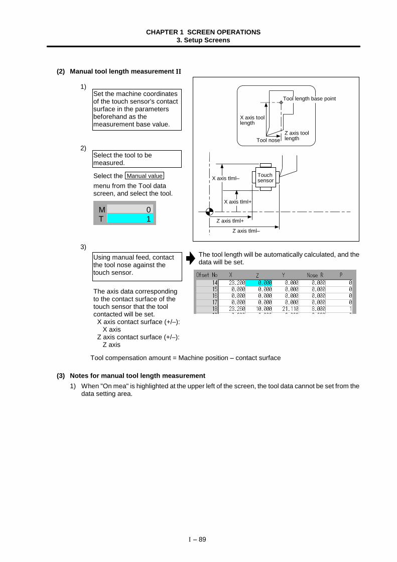
CHAPTER 1 SCREEN OPERATIONS3. Setup Screens
I – 89
(2) Manual tool length measurement IIIIIIII
1)
2)
3)The tool length will be automatically calculated, and thedata will be set.
Tool compensation amount = Machine position – contact surface
(3) Notes for manual tool length measurement1) When "On mea" is highlighted at the upper left of the screen, the tool data cannot be set from the
data setting area.
Using manual feed, contactthe tool nose against thetouch sensor.
Set the machine coordinatesof the touch sensor's contactsurface in the parametersbeforehand as themeasurement base value.
Select the tool to bemeasured.
Select the Manual valuemenu from the Tool datascreen, and select the tool.
TM 0
1
The axis data correspondingto the contact surface of thetouch sensor that the toolcontacted will be set.
X axis contact surface (+/–): X axisZ axis contact surface (+/–): Z axis
TouchsensorX axis tlml–
X axis tlml+
Z axis tlml+
Z axis tlml–
Tool length base point
X axis toollength
Z axis toollengthTool nose
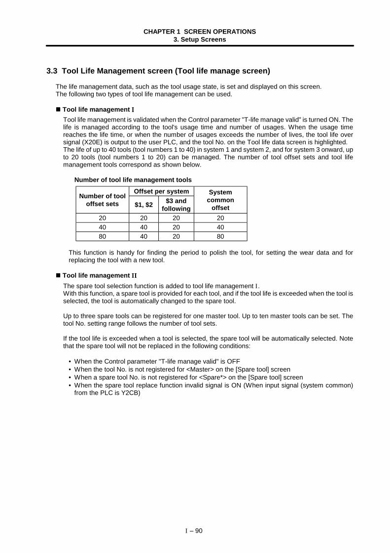
CHAPTER 1 SCREEN OPERATIONS3. Setup Screens
I – 90
3.3 Tool Life Management screen (Tool life manage screen)
The life management data, such as the tool usage state, is set and displayed on this screen.The following two types of tool life management can be used.
Tool life management IIIITool life management is validated when the Control parameter "T-life manage valid" is turned ON. Thelife is managed according to the tool's usage time and number of usages. When the usage timereaches the life time, or when the number of usages exceeds the number of lives, the tool life oversignal (X20E) is output to the user PLC, and the tool No. on the Tool life data screen is highlighted.The life of up to 40 tools (tool numbers 1 to 40) in system 1 and system 2, and for system 3 onward, upto 20 tools (tool numbers 1 to 20) can be managed. The number of tool offset sets and tool lifemanagement tools correspond as shown below.
Number of tool life management toolsOffset per system
Number of tooloffset sets $1, $2 $3 and
following
Systemcommon
offset20 20 20 2040 40 20 4080 40 20 80
This function is handy for finding the period to polish the tool, for setting the wear data and forreplacing the tool with a new tool.
Tool life management IIIIIIII
The spare tool selection function is added to tool life management I.With this function, a spare tool is provided for each tool, and if the tool life is exceeded when the tool isselected, the tool is automatically changed to the spare tool.
Up to three spare tools can be registered for one master tool. Up to ten master tools can be set. Thetool No. setting range follows the number of tool sets.
If the tool life is exceeded when a tool is selected, the spare tool will be automatically selected. Notethat the spare tool will not be replaced in the following conditions:
• When the Control parameter "T-life manage valid" is OFF• When the tool No. is not registered for <Master> on the [Spare tool] screen• When a spare tool No. is not registered for <Spare*> on the [Spare tool] screen• When the spare tool replace function invalid signal is ON (When input signal (system common)
from the PLC is Y2CB)
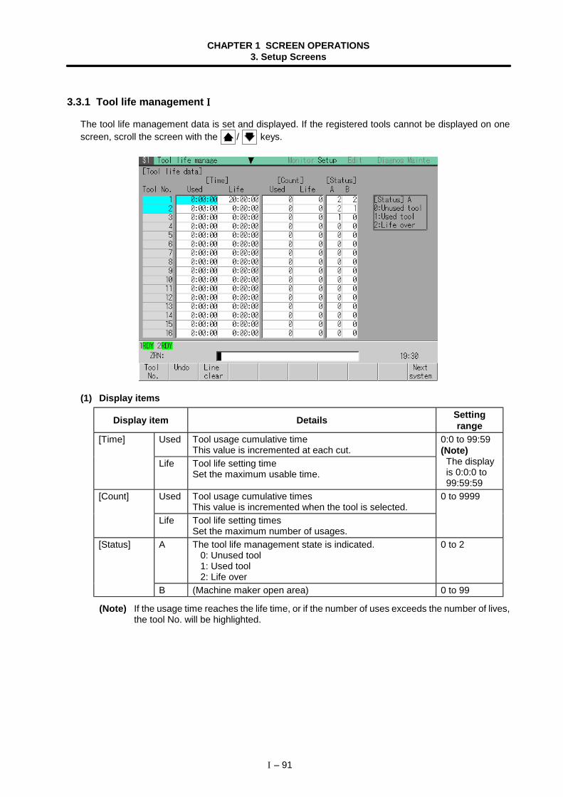
CHAPTER 1 SCREEN OPERATIONS3. Setup Screens
I – 91
3.3.1 Tool life management IIII
The tool life management data is set and displayed. If the registered tools cannot be displayed on onescreen, scroll the screen with the / keys.
(1) Display items
Display item Details Settingrange
Used Tool usage cumulative timeThis value is incremented at each cut.
[Time]
Life Tool life setting timeSet the maximum usable time.
0:0 to 99:59(Note)
The displayis 0:0:0 to99:59:59
Used Tool usage cumulative timesThis value is incremented when the tool is selected.
[Count]
Life Tool life setting timesSet the maximum number of usages.
0 to 9999
A The tool life management state is indicated. 0: Unused tool 1: Used tool 2: Life over
0 to 2[Status]
B (Machine maker open area) 0 to 99
(Note) If the usage time reaches the life time, or if the number of uses exceeds the number of lives,the tool No. will be highlighted.
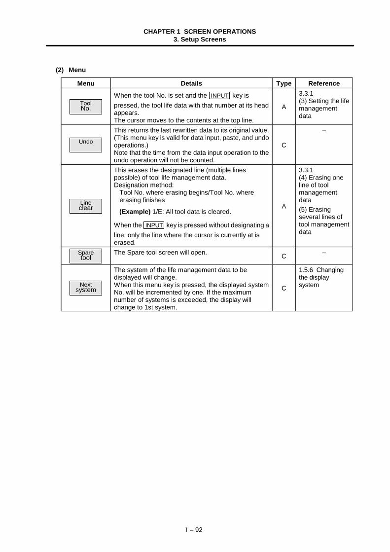
CHAPTER 1 SCREEN OPERATIONS3. Setup Screens
I – 92
(2) Menu
Menu Details Type Reference
ToolNo.
When the tool No. is set and the INPUT key ispressed, the tool life data with that number at its headappears.The cursor moves to the contents at the top line.
A
3.3.1(3) Setting the lifemanagementdata
Undo
This returns the last rewritten data to its original value.(This menu key is valid for data input, paste, and undooperations.)Note that the time from the data input operation to theundo operation will not be counted.
C
–
Lineclear
This erases the designated line (multiple linespossible) of tool life management data.Designation method:
Tool No. where erasing begins/Tool No. whereerasing finishes
(Example) 1/E: All tool data is cleared.
When the INPUT key is pressed without designating aline, only the line where the cursor is currently at iserased.
A
3.3.1(4) Erasing oneline of toolmanagementdata(5) Erasingseveral lines oftool managementdata
Sparetool
The Spare tool screen will open. C –
Nextsystem
The system of the life management data to bedisplayed will change.When this menu key is pressed, the displayed systemNo. will be incremented by one. If the maximumnumber of systems is exceeded, the display willchange to 1st system.
C
1.5.6 Changingthe displaysystem
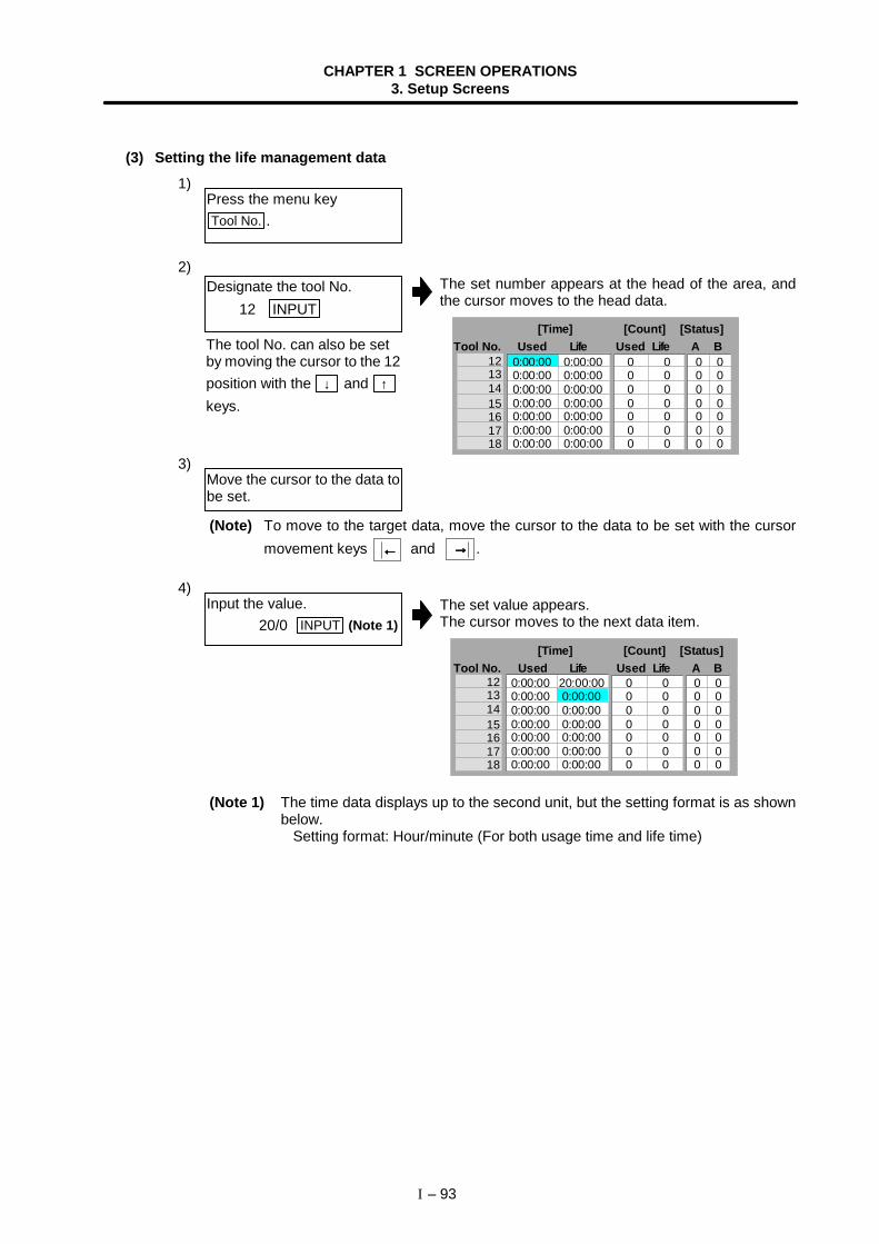
CHAPTER 1 SCREEN OPERATIONS3. Setup Screens
I – 93
(3) Setting the life management data1)
2)The set number appears at the head of the area, andthe cursor moves to the head data.
12131415161718
0 0 0 0 0 0 0
0 0 0 0 0 0
0 0 0 0 0 0 0
0 0 0 0 0 0
0:00:00 0:00:00 0:00:00 0:00:00 0:00:00 0:00:00 0:00:00
0:00:00 0:00:00 0:00:00 0:00:00 0:00:00 0:00:00 0:00:00
0 0Tool No.
[Time]Used Life
[Count]Used Life
[Status]A B
3)
(Note) To move to the target data, move the cursor to the data to be set with the cursormovement keys ←←←← and →→→→ .
4)The set value appears.The cursor moves to the next data item.
12131415161718
0 0 0 0 0 0 0
0 0 0 0 0 0
0 0 0 0 0 0 0
0 0 0 0 0 0
0:00:00 0:00:00 0:00:00 0:00:00 0:00:00 0:00:00 0:00:00
20:00:00 0:00:00 0:00:00 0:00:00 0:00:00 0:00:00 0:00:00
0 0Tool No.
[Time]Used Life
[Count]Used Life
[Status]A B
(Note 1) The time data displays up to the second unit, but the setting format is as shownbelow. Setting format: Hour/minute (For both usage time and life time)
Press the menu keyTool No. .
Designate the tool No. 12 INPUT
Move the cursor to the data tobe set.
Input the value.20/0 INPUT (Note 1)
The tool No. can also be setby moving the cursor to the 12position with the ↓ and ↑
keys.
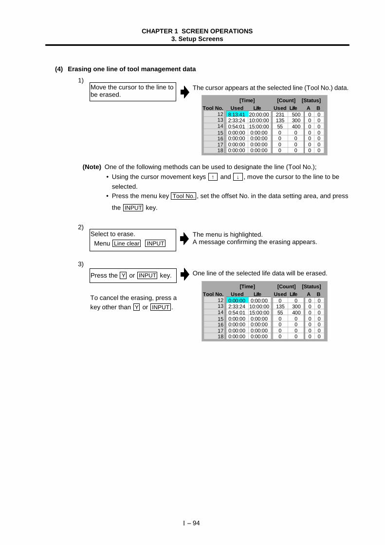
CHAPTER 1 SCREEN OPERATIONS3. Setup Screens
I – 94
(4) Erasing one line of tool management data1)
The cursor appears at the selected line (Tool No.) data.
12131415161718
231 135 55 0 0 0 0
300 400 0 0 0 0
0 0 0 0 0 0 0
0 0 0 0 0 0
8:13:41 2:33:24 0:54:01 0:00:00 0:00:00 0:00:00 0:00:00
20:00:0010:00:0015:00:00 0:00:00 0:00:00 0:00:00 0:00:00
500 0Tool No.
[Time]Used Life
[Count]Used Life
[Status]A B
(Note) One of the following methods can be used to designate the line (Tool No.); • Using the cursor movement keys ↑ and ↓ , move the cursor to the line to be
selected. • Press the menu key Tool No. , set the offset No. in the data setting area, and press
the INPUT key.
2)The menu is highlighted.A message confirming the erasing appears.
3)One line of the selected life data will be erased.
12131415161718
0 135 55 0 0 0 0
300 400 0 0 0 0
0 0 0 0 0 0 0
0 0 0 0 0 0
0:00:00 2:33:24 0:54:01 0:00:00 0:00:00 0:00:00 0:00:00
0:00:0010:00:0015:00:00 0:00:00 0:00:00 0:00:00 0:00:00
0 0Tool No.
[Time]Used Life
[Count]Used Life
[Status]A B
Press the Y or INPUT key.
Move the cursor to the line tobe erased.
Select to erase. Menu Line clear INPUT
To cancel the erasing, press akey other than Y or INPUT .
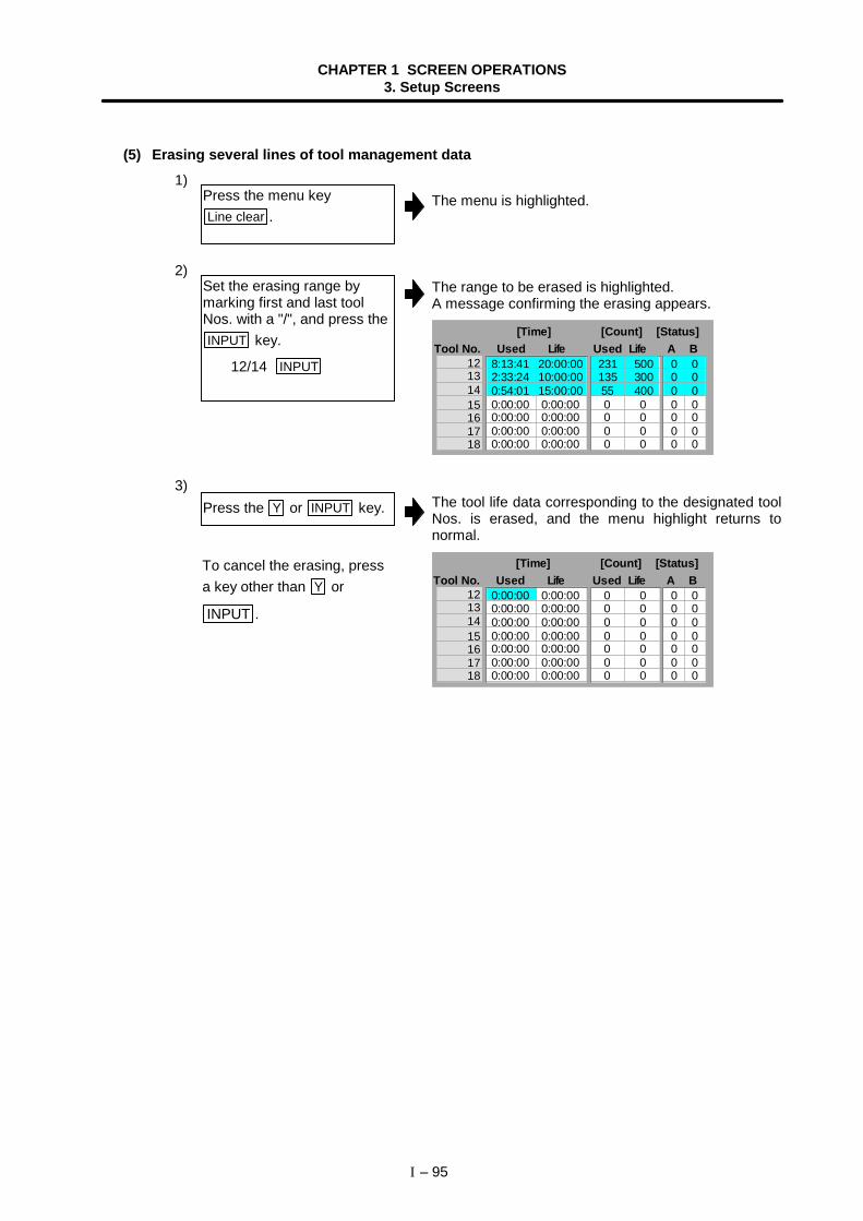
CHAPTER 1 SCREEN OPERATIONS3. Setup Screens
I – 95
(5) Erasing several lines of tool management data1)
The menu is highlighted.
2)The range to be erased is highlighted.A message confirming the erasing appears.
12131415161718
0 0 0 0
0 0 0 0
0 0 0 0
0 0 0 0
8:13:41 2:33:24 0:54:01 0:00:00 0:00:00 0:00:00 0:00:00
20:00:0010:00:0015:00:00 0:00:00 0:00:00 0:00:00 0:00:00
231 135 55
300 400
500 0 0 0
0 0
0Tool No.
[Time]Used Life
[Count]Used Life
[Status]A B
3)The tool life data corresponding to the designated toolNos. is erased, and the menu highlight returns tonormal.
12131415161718
0 0 0 0 0 0 0
0 0 0 0 0 0
0 0 0 0 0 0 0
0 0 0 0 0 0
0:00:00 0:00:00 0:00:00 0:00:00 0:00:00 0:00:00 0:00:00
0:00:00 0:00:00 0:00:00 0:00:00 0:00:00 0:00:00 0:00:00
0 0Tool No.
[Time]Used Life
[Count]Used Life
[Status]A B
Press the menu keyLine clear .
Set the erasing range bymarking first and last toolNos. with a "/", and press theINPUT key.
12/14 INPUT
To cancel the erasing, pressa key other than Y or
INPUT .
Press the Y or INPUT key.
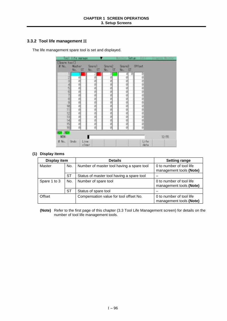
CHAPTER 1 SCREEN OPERATIONS3. Setup Screens
I – 96
3.3.2 Tool life management IIIIIIII
The life management spare tool is set and displayed.
(1) Display itemsDisplay item Details Setting range
No. Number of master tool having a spare tool 0 to number of tool lifemanagement tools (Note)
Master
ST Status of master tool having a spare tool –No. Number of spare tool 0 to number of tool life
management tools (Note)Spare 1 to 3
ST Status of spare tool –Offset Compensation value for tool offset No. 0 to number of tool life
management tools (Note)
(Note) Refer to the first page of this chapter (3.3 Tool Life Management screen) for details on thenumber of tool life management tools.
CHAPTER 1 SCREEN OPERATIONS3. Setup Screens
I – 97
(2) Menus
Menu Details Type Reference
# No.When the # No. is set and the INPUT key is pressed,the tool change data with that number at its headappears.The cursor moves to the contents at the top line.
A
3.3.2(3) Setting the lifemanagementspare tool
Undo This returns the last rewritten data to its original value.(This menu key is valid for data input, paste, and undooperations.)
C–
Lineclear
This erases the designated line (multiple linespossible) of tool change data.Designation method:
# No. where erasing begins/# No. where erasingfinishes
(Example) 1/E: All data is cleared.
When the INPUT key is pressed without designating aline, only the line where the cursor is currently at iserased.
A
3.3.2(4) Erasing oneline of spare tooldata(5) Erasingseveral lines ofspare tool data
Lifedata
The [Tool life data] screen (1st page of Tool lifemanage screen) will open. C –
Nextsystem
The system of the life management data to bedisplayed will change.When this menu key is pressed, the displayed systemNo. will be incremented by one. If the maximumnumber of systems is exceeded, the display willchange to 1st system.
C
1.5.6 Changingthe displaysystem
CHAPTER 1 SCREEN OPERATIONS3. Setup Screens
I – 98
(3) Setting the life management spare tool1)
2)The cursor moves the head data of the set tool No.
3)
(Note) To move to the target data, move the cursor to the data to be set with the cursormovement keys ←←←← and →→→→ .
4)The set value appears.The cursor moves to the next data item.
Press the menu key # No. .
Designate the # No. 3 INPUT
Move the cursor to the data tobe set.
Input the value.20 INPUT
The tool No. can also be setby moving the cursor to the 3position with the ↓ and ↑
keys.
CHAPTER 1 SCREEN OPERATIONS3. Setup Screens
I – 99
(4) Erasing one line of spare tool data1)
The cursor appears at the selected line (# No.) data.
(Note) One of the following methods can be used to designate the line (#No.); • Using the cursor movement keys ↑ and ↓ , move the cursor to the line to be
selected. • Press the menu key Tool No. , set the offset No. in the data setting area, and press
the INPUT key.
2)The menu is highlighted.A message confirming the erasing appears.
3)One line of the selected spare tool data will be erased.Press the Y or INPUT key.
Move the cursor to the line tobe erased.
Select to erase. Menu Line clear INPUT
To cancel the erasing, press akey other than Y or INPUT .
CHAPTER 1 SCREEN OPERATIONS3. Setup Screens
I – 100
(5) Erasing several lines of spare tool data1)
The menu is highlighted.
2)The range to be erased is highlighted.A message confirming the erasing appears.
3)The spare tool data corresponding to the designatedtool Nos. is erased, and the menu highlight returns tonormal.
Press the menu keyLine clear .
Set the erasing range bymarking first and last toolNos. with a "/", and press theINPUT key.
3/5 INPUT
To cancel the erasing, pressa key other than Y or
INPUT .
Press the Y or INPUT key.
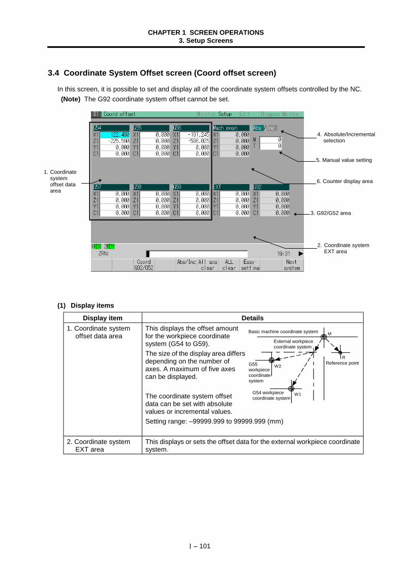
CHAPTER 1 SCREEN OPERATIONS3. Setup Screens
I – 101
3.4 Coordinate System Offset screen (Coord offset screen)
In this screen, it is possible to set and display all of the coordinate system offsets controlled by the NC. (Note) The G92 coordinate system offset cannot be set.
(1) Display items
Display item Details1. Coordinate system
offset data areaThis displays the offset amountfor the workpiece coordinatesystem (G54 to G59).The size of the display area differsdepending on the number ofaxes. A maximum of five axescan be displayed.
The coordinate system offsetdata can be set with absolutevalues or incremental values.Setting range: –99999.999 to 99999.999 (mm)
2. Coordinate systemEXT area
This displays or sets the offset data for the external workpiece coordinatesystem.
1. Coordinatesystemoffset dataarea
M
R
W1
W2
Basic machine coordinate system
External workpiececoordinate system
G55workpiececoordinatesystem
Reference point
G54 workpiececoordinate system
4. Absolute/Incremental selection
5. Manual value setting
6. Counter display area
3. G92/G52 area
2. Coordinate systemEXT area
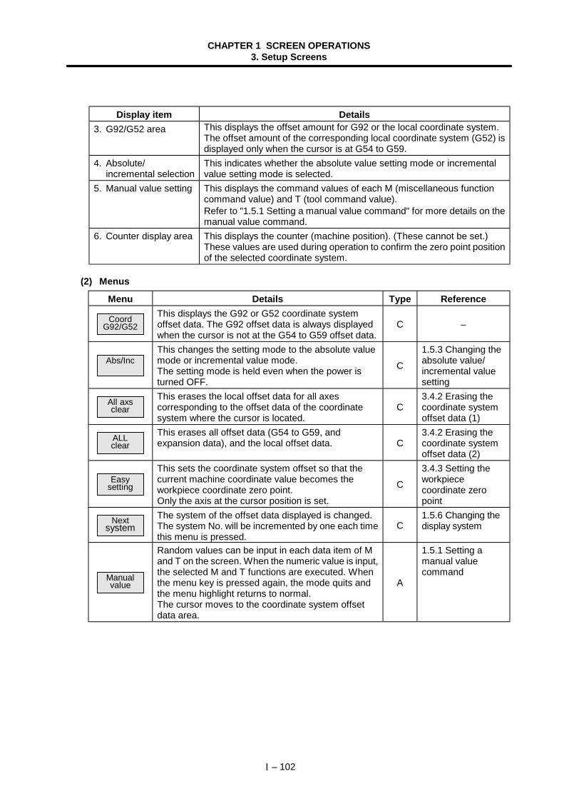
CHAPTER 1 SCREEN OPERATIONS3. Setup Screens
I – 102
Display item Details3. G92/G52 area This displays the offset amount for G92 or the local coordinate system.
The offset amount of the corresponding local coordinate system (G52) isdisplayed only when the cursor is at G54 to G59.
4. Absolute/incremental selection
This indicates whether the absolute value setting mode or incrementalvalue setting mode is selected.
5. Manual value setting This displays the command values of each M (miscellaneous functioncommand value) and T (tool command value).Refer to "1.5.1 Setting a manual value command" for more details on themanual value command.
6. Counter display area This displays the counter (machine position). (These cannot be set.)These values are used during operation to confirm the zero point positionof the selected coordinate system.
(2) Menus
Menu Details Type Reference
CoordG92/G52
This displays the G92 or G52 coordinate systemoffset data. The G92 offset data is always displayedwhen the cursor is not at the G54 to G59 offset data.
C –
Abs/IncThis changes the setting mode to the absolute valuemode or incremental value mode.The setting mode is held even when the power isturned OFF.
C
1.5.3 Changing theabsolute value/incremental valuesetting
All axsclear
This erases the local offset data for all axescorresponding to the offset data of the coordinatesystem where the cursor is located.
C3.4.2 Erasing thecoordinate systemoffset data (1)
ALLclear
This erases all offset data (G54 to G59, andexpansion data), and the local offset data. C
3.4.2 Erasing thecoordinate systemoffset data (2)
Easysetting
This sets the coordinate system offset so that thecurrent machine coordinate value becomes theworkpiece coordinate zero point.Only the axis at the cursor position is set.
C
3.4.3 Setting theworkpiececoordinate zeropoint
Nextsystem
The system of the offset data displayed is changed.The system No. will be incremented by one each timethis menu is pressed.
C1.5.6 Changing thedisplay system
Manualvalue
Random values can be input in each data item of Mand T on the screen. When the numeric value is input,the selected M and T functions are executed. Whenthe menu key is pressed again, the mode quits andthe menu highlight returns to normal.The cursor moves to the coordinate system offsetdata area.
A
1.5.1 Setting amanual valuecommand
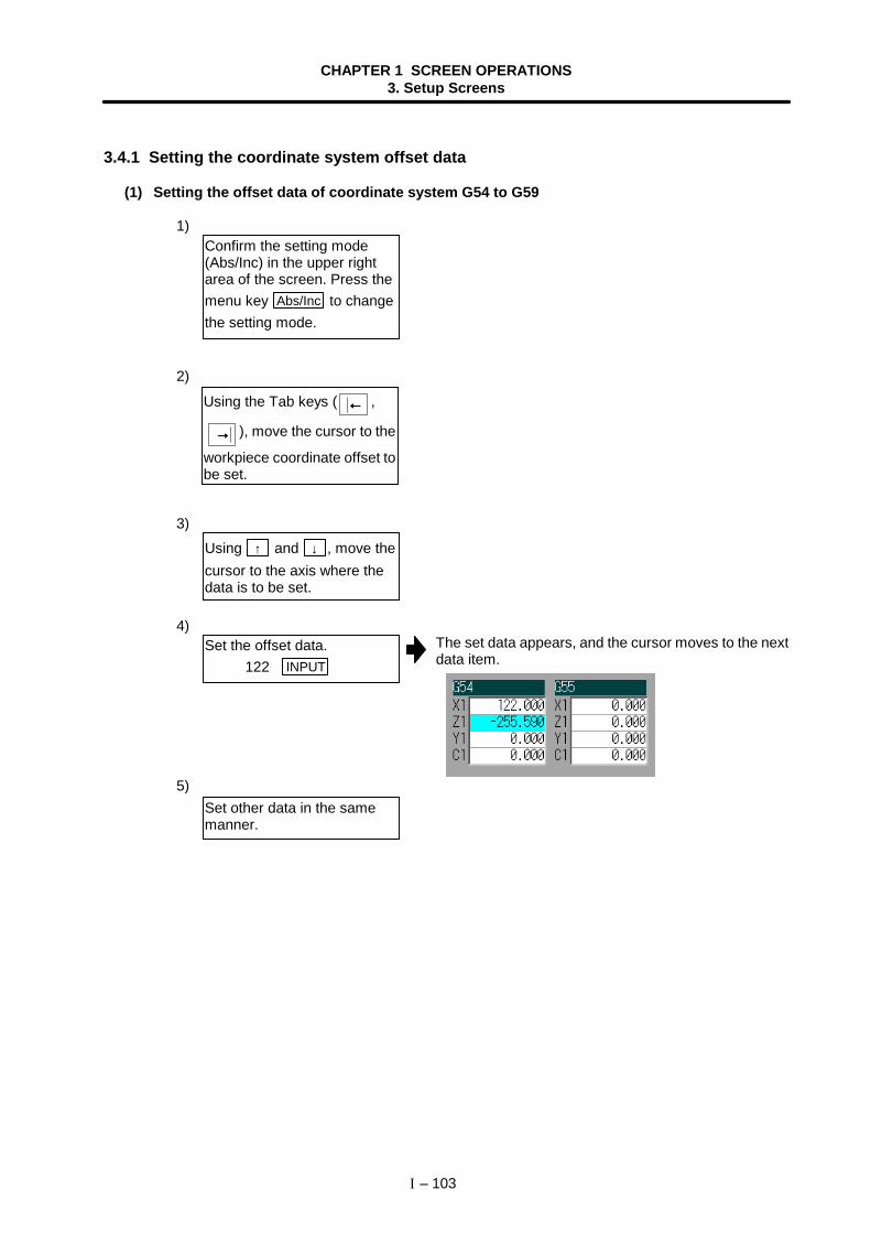
CHAPTER 1 SCREEN OPERATIONS3. Setup Screens
I – 103
3.4.1 Setting the coordinate system offset data
(1) Setting the offset data of coordinate system G54 to G59
1)
2)
3)
4)The set data appears, and the cursor moves to the nextdata item.
5)
Using the Tab keys ( ←←←← ,
→→→→ ), move the cursor to the
workpiece coordinate offset tobe set.
Using ↑ and ↓ , move thecursor to the axis where thedata is to be set.
Set the offset data. 122 INPUT
Set other data in the samemanner.
Confirm the setting mode(Abs/Inc) in the upper rightarea of the screen. Press themenu key Abs/Inc to changethe setting mode.
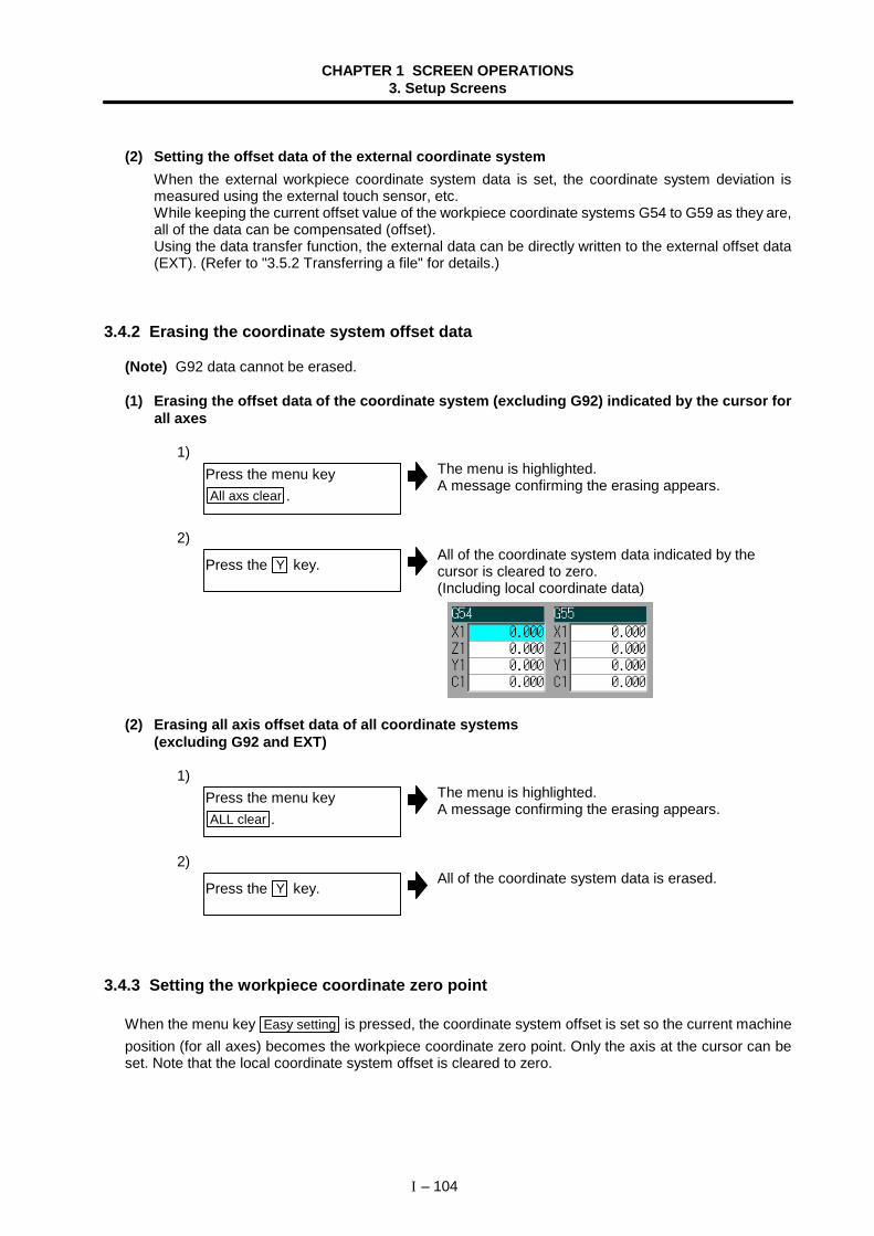
CHAPTER 1 SCREEN OPERATIONS3. Setup Screens
I – 104
(2) Setting the offset data of the external coordinate systemWhen the external workpiece coordinate system data is set, the coordinate system deviation ismeasured using the external touch sensor, etc.While keeping the current offset value of the workpiece coordinate systems G54 to G59 as they are,all of the data can be compensated (offset).Using the data transfer function, the external data can be directly written to the external offset data(EXT). (Refer to "3.5.2 Transferring a file" for details.)
3.4.2 Erasing the coordinate system offset data
(Note) G92 data cannot be erased.
(1) Erasing the offset data of the coordinate system (excluding G92) indicated by the cursor forall axes
1)The menu is highlighted.A message confirming the erasing appears.
2)All of the coordinate system data indicated by thecursor is cleared to zero.(Including local coordinate data)
(2) Erasing all axis offset data of all coordinate systems(excluding G92 and EXT)
1)The menu is highlighted.A message confirming the erasing appears.
2)All of the coordinate system data is erased.
3.4.3 Setting the workpiece coordinate zero point
When the menu key Easy setting is pressed, the coordinate system offset is set so the current machineposition (for all axes) becomes the workpiece coordinate zero point. Only the axis at the cursor can beset. Note that the local coordinate system offset is cleared to zero.
Press the menu keyAll axs clear .
Press the Y key.
Press the menu keyALL clear .
Press the Y key.
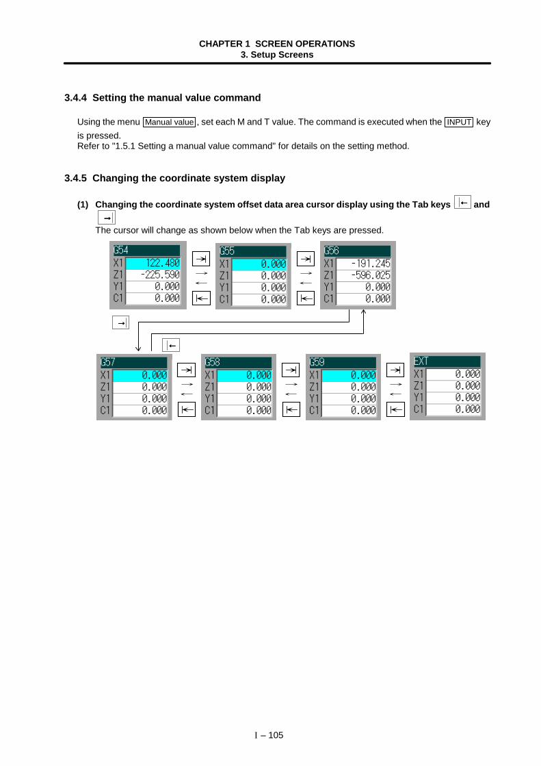
CHAPTER 1 SCREEN OPERATIONS3. Setup Screens
I – 105
3.4.4 Setting the manual value command
Using the menu Manual value , set each M and T value. The command is executed when the INPUT keyis pressed.Refer to "1.5.1 Setting a manual value command" for details on the setting method.
3.4.5 Changing the coordinate system display
(1) Changing the coordinate system offset data area cursor display using the Tab keys ←←←← and→→→→
The cursor will change as shown below when the Tab keys are pressed.
→→→→
←←←←
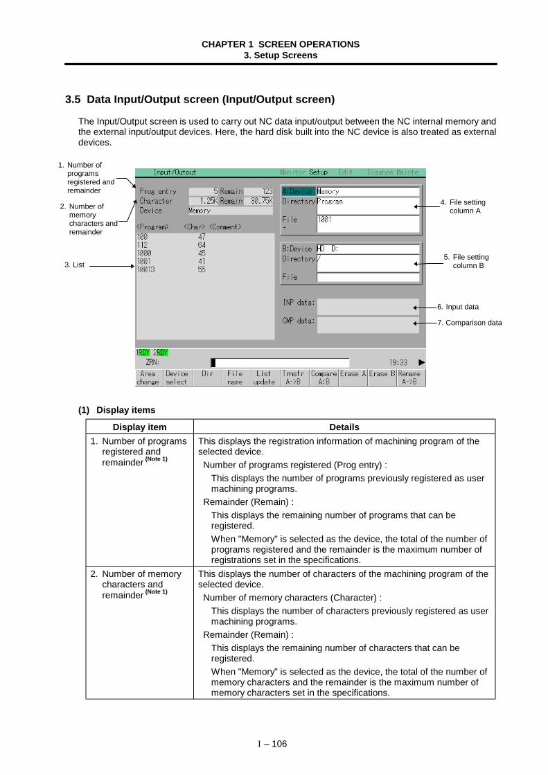
CHAPTER 1 SCREEN OPERATIONS3. Setup Screens
I – 106
3.5 Data Input/Output screen (Input/Output screen)
The Input/Output screen is used to carry out NC data input/output between the NC internal memory andthe external input/output devices. Here, the hard disk built into the NC device is also treated as externaldevices.
(1) Display items
Display item Details1. Number of programs
registered andremainder (Note 1)
This displays the registration information of machining program of theselected device. Number of programs registered (Prog entry) :
This displays the number of programs previously registered as usermachining programs.
Remainder (Remain) :This displays the remaining number of programs that can beregistered.When "Memory" is selected as the device, the total of the number ofprograms registered and the remainder is the maximum number ofregistrations set in the specifications.
2. Number of memorycharacters andremainder (Note 1)
This displays the number of characters of the machining program of theselected device. Number of memory characters (Character) :
This displays the number of characters previously registered as usermachining programs.
Remainder (Remain) :This displays the remaining number of characters that can beregistered.When "Memory" is selected as the device, the total of the number ofmemory characters and the remainder is the maximum number ofmemory characters set in the specifications.
3. List
1. Number ofprogramsregistered andremainder
4. File settingcolumn A
6. Input data
5. File settingcolumn B
2. Number ofmemorycharacters andremainder
7. Comparison data
CHAPTER 1 SCREEN OPERATIONS3. Setup Screens
I – 107
Display item Details3. List This displays a contents list (directory and file name) of the directory in
the setting column (file setting column A or B) where the cursor iscurrently located.
<Program> :When "Memory" is selected for the device, this displays the file name(program No.) of the machining programs already registered.The file names are displayed in order from the smallest number, from1 to 99999999.When a device other than "Memory" is selected, this displays the filename and directory to be included in the directory that is set in thecurrent setting column.
<Char>:The size of each file (when "Memory" is selected for the device, thenumber of characters in the machining program).When directory is selected, this displays "DIR".
<Comment> :This displays the comment (up to 18 alphanumeric characters andsymbols) of each file.
(Note 1) For an HD or FLD file, the date and time will be displayed as acomment.
4. File setting column A This sets the device, directory, and file name of the target file for transfer,compare, erasing, etc., operations.When transferring, the file name of the transfer origin file is set. Whenrenaming, the file name before renaming is set.When erasing, the erasing range is set.
5. File setting column B This sets the device, directory, and file name of the target file for transfer,compare, erasing etc., operations.When transferring, the file name of the transfer destination file is set.When renaming, the file name after renaming is set.When erasing, the erasing file name is set.
6. Input data This displays the data being transferred.7. Comparison data This displays the data being compared. If an error occurs during
comparison, the block with the error is displayed.
(Note 1) Depending on the device, some items are not displayed.
DeviceDisplay item
Memory RS-232C HD FLD
Prog entry ×Remain × × ×Character ×Remain ×List ×
: Displayed × : Not displayed
CHAPTER 1 SCREEN OPERATIONS3. Setup Screens
I – 108
(2) Menus
Menu Details Type Reference
Areachange
This changes the setting area to file setting column A(transfer origin) or file setting column B (transferdestination). The display of the valid area (A or B) ishighlighted.
C
1.5.2 Changingthe valid area
Deviceselect
This displays the submenu of the machining programstorage area.When the submenu is selected, the device is fixed,and if a directory exists it is set in the root. Thememory is selected as the default.
A
3.5.1 Selecting adevice, directoryand file
DirThis menu sets the directory that carries outinput/output operations, and is on standby for input.Note that when "Memory" is selected for the device,the directory can be selected from the submenu.
A
Filename
This menu sets the file name that carries outinput/output operations, and is on standby for input.When "Memory" is selected for the device, setting isnot necessary if the directory is not the program.
A
Listupdate
This updates the list. The list of the directory selectedin the currently valid file setting column (A/B) isupdated.
C−
TrnsfrA -> B
This copies the file in file setting column A (transferorigin) to the file setting column B (transferdestination). (The transfer origin file is not changed.) Amessage appears during transfer and when thetransfer is completed.
B
3.5.2Transferring a file
CompareA:B
This compares the files in file setting column A(transfer origin) and file setting column B (transferdestination).(Note) Normally only one file can be compared,
however, with the RS-232C, multiple files canbe compared.
C
3.5.3 Comparingfiles (Compare)
Erase A This erases the file in file setting column A. B 3.5.4 Erasing afile
Erase B This erases the file in file setting column B. B 3.5.4 Erasing afile
RenameA -> B
This changes the name of the file in file setting columnA (transfer origin) to the name of the file in file settingcolumn B (transfer destination).(Note) The same device must be selected for A and
B.
B
3.5.5Changing a filename (Rename)
Dircreate
This creates a new directory in the directory of thecurrently valid file setting column (A/B).The directory can be created when HD or FLD isselected for the device.
A
3.5.6Creating adirectory
FLDformat
This formats the FLD.B
3.5.7Formatting anFLD
Stop This interrupts the process (transfer, compare, etc.)during execution. C –
CHAPTER 1 SCREEN OPERATIONS3. Setup Screens
I – 109
3.5.1 Selecting a device, directory and file
This section explains the methods of designating the device, directory and file name of the target file foroperations such as file transfer and erasing carried out on this screen.
(1) File selection sequence
(2) Menus used
Device select menu submenus
Menu Details Type ReferenceMemory This selects the memory. C –
RS232C This selects the RS-232C (including tape). C –
FLD A: The FLD is selected.The drive name will appear at the right side. C –
HD D: The HD (hard disk) is selected. The drive name willappear at the right side. C –
Dir (other than memory) and File name menu submenus
Menu Details Type Reference
Fromlist
The cursor appears in the list display. The list contentscan be selected with the INPUT key.When a directory is selected, the contents of theselected directory are displayed in the list. Continuedselection is possible.When a file name is selected, the file name istemporarily displayed in the data setting area. Whenthe INPUT key is pressed again, it is fixed.
A
Designate the device where the target file exists. → Select from the submenu.
Designate the directory with full path. → Key input the full path, or selectfrom the submenu.
↓
Designate the file name. → Key input the file name, or selectfrom the submenu.
↓
CHAPTER 1 SCREEN OPERATIONS3. Setup Screens
I – 110
Outline of device, directory, and file name setting methods
Designation methodDevice Designation target file
Device Directory File nameNCmemory
• Machining program• User macro• Fixed cycle program
Select from thesubmenu
–(Default)
Key input in thedata setting area,and press
INPUT
Select from thelistSelect from thesubmenu
File other than themachining program
Select from thesubmenu
Select from thesubmenu
Select from thelist
Key input in thedata setting area,and press
INPUT
Key input in thedata setting area,and press
INPUT
Deviceother thanthe NCmemory
All files Select from thesubmenu
Select from thelist
Select from thelist
The device can be selected from the submenu. (The devices that can be used will differ dependingon the specifications.)One of the following methods can be used to designate the directory (for devices other than the NCmemory) and file name.
• Set the directory path (full path) or file name in the data setting area, and press the INPUT key.
• Press submenu From list of the menu Dir or File name . Move the cursor to the target directoryor file name, and press the key.
A wild card (∗ ) can be used when selecting a file name.
Notes when selecting a file
(Note 1) During directory and file name setting, the designated directory, path or file name will beset, even if it does not actually exist. This will not cause an error. Note that the previouslyset directory is overwritten.
(Note 2) When designating a file other than a machining program in the NC memory, select the filename from the submenu. (The file name is fixed.)
(Note 3) When a file name is selected from the menu, it first is displayed in the data setting area.However, at this time the file name has not yet been fixed. Press the INPUT key again tofix the file name.
(Note 4) When the key is pressed when setting a file name, the file name in the data settingarea is erased.
(Note 5) When a Fixed cycle program is designated, the Basic common parameter 1306 "fix_P"must be set. Select "Memory" for the device, and "Program" for the directory.
INPUT
CHAPTER 1 SCREEN OPERATIONS3. Setup Screens
I – 111
(3) Selecting an NC memory program
1)The following menu appears.
Memory RS232C FLD A: HD D:
2)"Memory" appears in the device name, and the default"Program" appears in the directory.
3)The following menu appears.
Fromlist
•••• When inputting from the data setting area4)
•••• When selecting the file name from the list4)-1
The cursor appears in the list.
<Program> <Char> <Comment>
10015 80 93.01.20 13:43 10014 162 93.01.20 13:43
10012 130 93.01.20 13:43
10016 160 93.01.20 13:43
10013 100 93.01.20 13:43
10011 518 93.01.20 13:43
4)-2The selected file name appears in the data setting area.
4)-3The selected file name appears.
Press the menuDevice select .
Press the menu Memory .
Press the menu File name .
Input the file name. 10013 INPUT
Press the menu From list .
Move the cursor to file nameto be selected, and fix. ↑ , ↓ INPUT
Press the INPUT key.
CHAPTER 1 SCREEN OPERATIONS3. Setup Screens
I – 112
(4) Designating multiple filesMultiple serial files can be transferred and erased in the file setting column A. Set as follows in thiscase.
(5) Selecting an NC memory file other than a program1)
The following menu appears.
Memory RS232C FLD A: HD D:
2)"Memory" appears in the device name, and the default"Program" appears in the directory.
3)The following menu appears.
List Program Param PLCprog
NC data
4)The names of the NC data files will be listed.
5)The following menu will appear.
List Tooloffset
Workoffset
Commonvariabl
Customvariabl
SRAMdata
6)Directory and file name will appear.
(Note) Refer to "3.5.8 List of file names" for details on the file names.
Press the menuDevice select .
Press the menu Memory .
Select the menu Dir .
Press the menu NC data .
Press the menu File name .
Select the required file fromthe menu.
File : First file name – : Last file name
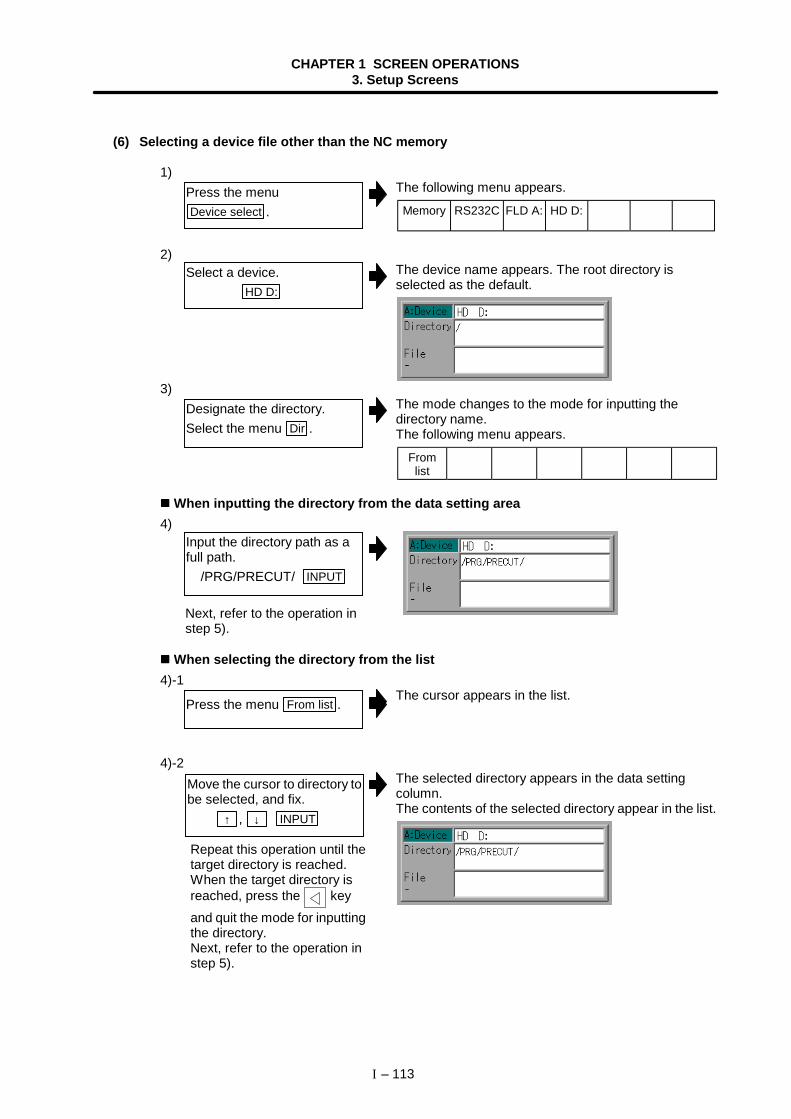
CHAPTER 1 SCREEN OPERATIONS3. Setup Screens
I – 113
(6) Selecting a device file other than the NC memory
1)The following menu appears.
Memory RS232C FLD A: HD D:
2)The device name appears. The root directory isselected as the default.
3)The mode changes to the mode for inputting thedirectory name.The following menu appears.
Fromlist
When inputting the directory from the data setting area4)
When selecting the directory from the list4)-1
The cursor appears in the list.
4)-2The selected directory appears in the data settingcolumn.The contents of the selected directory appear in the list.
Press the menuDevice select .
Select a device. HD D:
Designate the directory.Select the menu Dir .
Input the directory path as afull path. /PRG/PRECUT/ INPUT
Press the menu From list .
Move the cursor to directory tobe selected, and fix. ↑ , ↓ INPUT
Repeat this operation until thetarget directory is reached.When the target directory isreached, press the keyand quit the mode for inputtingthe directory.Next, refer to the operation instep 5).
Next, refer to the operation instep 5).
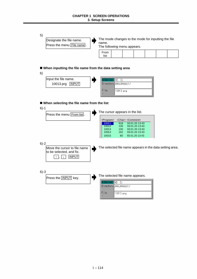
CHAPTER 1 SCREEN OPERATIONS3. Setup Screens
I – 114
5)The mode changes to the mode for inputting the filename.The following menu appears.
Fromlist
When inputting the file name from the data setting area6)
When selecting the file name from the list6)-1
The cursor appears in the list.
<Program> <Char> <Comment>
10015 80 93.01.20 13:43 10014 162 93.01.20 13:43
10012 130 93.01.20 13:43
10016 160 93 01 20 13 43
10013 100 93.01.20 13:43
10011 518 93.01.20 13:43
6)-2The selected file name appears in the data setting area.
6)-3The selected file name appears.
Designate the file name.Press the menu File name .
Input the file name. 10013.prg INPUT
Press the menu From list .
Move the cursor to file nameto be selected, and fix. ↑ , ↓ INPUT
Press the INPUT key.
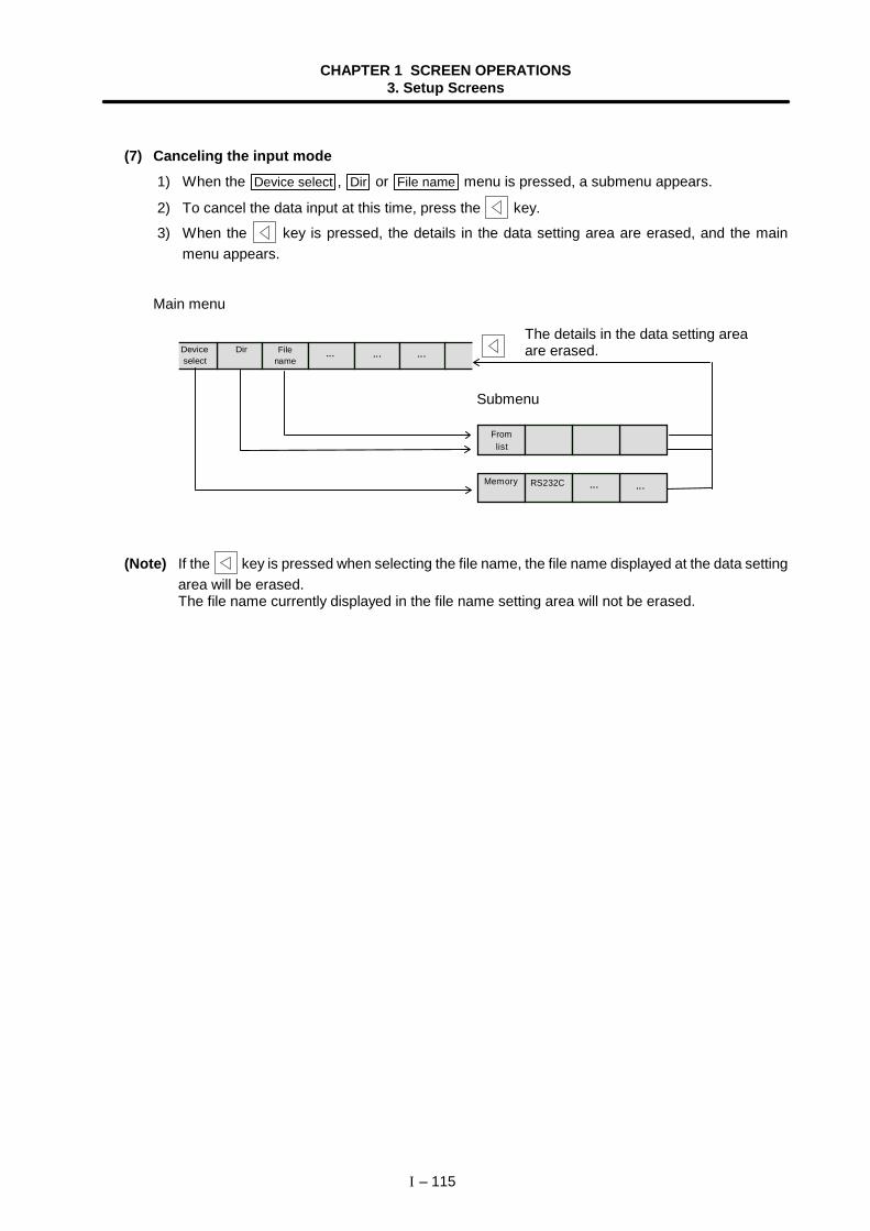
CHAPTER 1 SCREEN OPERATIONS3. Setup Screens
I – 115
(7) Canceling the input mode 1) When the Device select , Dir or File name menu is pressed, a submenu appears.
2) To cancel the data input at this time, press the key.
3) When the key is pressed, the details in the data setting area are erased, and the mainmenu appears.
Main menu
Dir Filename
... ... ...Deviceselect
Submenu
Fromlist
Memory RS232C ... ...
(Note) If the key is pressed when selecting the file name, the file name displayed at the data settingarea will be erased.The file name currently displayed in the file name setting area will not be erased.
The details in the data setting areaare erased.
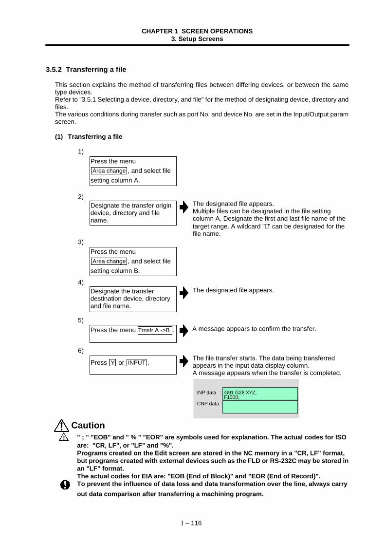
CHAPTER 1 SCREEN OPERATIONS3. Setup Screens
I – 116
3.5.2 Transferring a file
This section explains the method of transferring files between differing devices, or between the sametype devices.Refer to "3.5.1 Selecting a device, directory, and file" for the method of designating device, directory andfiles.The various conditions during transfer such as port No. and device No. are set in the Input/Output paramscreen.
(1) Transferring a file
1)
2)
3)
4)
5)
6)The file transfer starts. The data being transferredappears in the input data display column.A message appears when the transfer is completed.
INP data : G91 G28 XYZ;
F1000;CNP data :
! " ; " "EOB" and " % " "EOR" are symbols used for explanation. The actual codes for ISO
are: "CR, LF", or "LF" and "%".Programs created on the Edit screen are stored in the NC memory in a "CR, LF" format,but programs created with external devices such as the FLD or RS-232C may be stored inan "LF" format.The actual codes for EIA are: "EOB (End of Block)" and "EOR (End of Record)".
To prevent the influence of data loss and data transformation over the line, always carryout data comparison after transferring a machining program.
Press the menuArea change , and select file
setting column A.
Designate the transfer origindevice, directory and filename.
Press the menuArea change , and select file
setting column B.
Designate the transferdestination device, directoryand file name.
Press the menu Trnsfr A ->B .
Press Y or INPUT .
The designated file appears.Multiple files can be designated in the file settingcolumn A. Designate the first and last file name of thetarget range. A wildcard "∗ " can be designated for thefile name.
The designated file appears.
A message appears to confirm the transfer.
Caution
CHAPTER 1 SCREEN OPERATIONS3. Setup Screens
I – 117
(2) Notes
Notes related to transferring in general 1) Depending on the type of file, some data cannot be transferred during automatic operation. Do
not transfer during automatic operation. 2) When the capacity of the transfer destination is reached during file transfer, only the data
transferred up to that point is registered as a file, and an error will result. 3) During input to the NC memory or comparison, if the file format size on the NC memory side
differs from the other side file format size (when the maximum number of registrations differsbetween the NC memory and the other side), processing is carried out matched to the smallersize. (Ex. 1) If a format size of 200 files is input for a format size of 1000 NC files, 200 files are
registered. (Ex. 2) If a format size of1000 files is input for a format size of 200 NC files, the files up to the
200th file are registered and an error message appears. (The remaining files are notregistered.)
Notes when transferring machining program files 1) For the RS-232C, always set feed (Null) at both ends of the "EOR" code at the head and end. If
"EOB" etc., is directly after "EOR", the operation may not execute normally due to the inputbuffer influence during the next input operation.
2) The baud rate is slower if there are many registrations. 3) The size of one block of the machining program transferred should be 250 characters or less. 4) When using tape, carry out parity V adjustment to improve the reliability of the tape format. Then
use with the Input/output parameter "Parity V" validated. 5) When the machine manufacturer macro and Fixed cycle program are input, change the
program type with the parameter (fix_P). Also, set in the Input/Output screen as follows. Device: Memory, Directory: Program
6) With machining program created before the MELDAS500 Series, "EOB" is registered as "LF".However, when these programs are stored in the MELDAS600 Series NC memory, "EOB" willbe converted to "CR LF", and the number of characters will increase. Thus, when all of themachining programs output from an MELDAS500 Series or earlier NC, having the samespecifications as the maximum memory capacity, are stored in the MELDAS600 Series NCmemory, the memory capacity may be exceeded.
Notes when transferring parameter files 1) In the same manner as when setting in the Parameter screen, there are parameters validated
immediately after input, and parameters validated after a restart. Restart when a parameter filehas been transferred to the NC memory.
2) When a parameter file is transferred to the NC memory, the setting value of the Input/outputparameters is also changed. Before transferring again, set the Input/output parameters again.
Notes when transferring common variable data files 1) If the variable value is 100000 or more or less than 0.0001 when transferring common variable
data, it is expressed with an exponential expression.
CHAPTER 1 SCREEN OPERATIONS3. Setup Screens
I – 118
3.5.3 Comparing files (Compare)
This section explains the method of comparing transferred files.Refer to "3.5.1 Selecting a device, directory and file" for the method of designating a device, directory andfile.
(1) Comparing files
1)
2)The designated file name appears.
3)
4)The designated file name appears.
5)The file comparison starts. The data being comparedappears in the comparison data display column.A message appears when the comparison iscompleted.If a comparison error occurs, the block with the error isdisplayed in the comparison data display column on thescreen.
(Note) Comparison is not possible for blocks having 251 characters or more when files arecompared on the Input/Output screen. (An error occurs.)The size of one block of data should be within 250 characters.
Press the menuArea change , and select file
setting column A.
Designate the device,directory and file name to becompared.
Press the menuArea change , and select file
setting column B.
Designate the other sidedevice, directory and filename to be compared.
Press the menuCompare A:B .
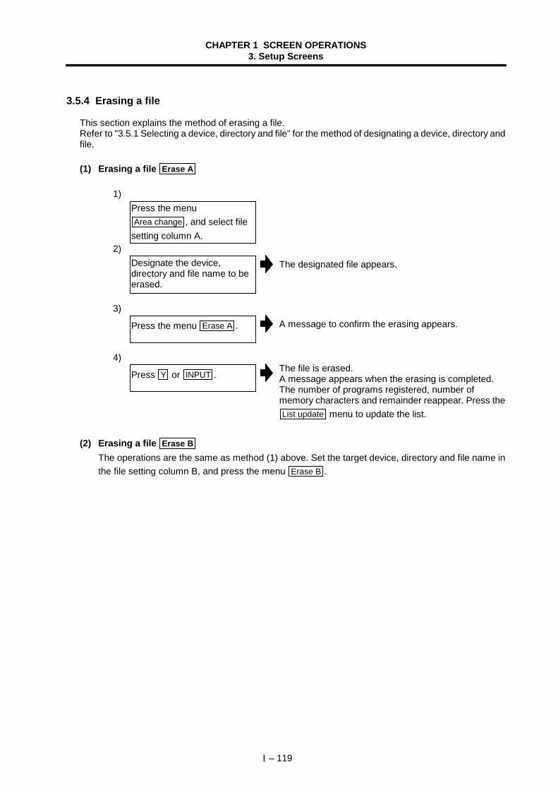
CHAPTER 1 SCREEN OPERATIONS3. Setup Screens
I – 119
3.5.4 Erasing a file
This section explains the method of erasing a file.Refer to "3.5.1 Selecting a device, directory and file" for the method of designating a device, directory andfile.
(1) Erasing a file Erase A
1)
2)The designated file appears.
3)A message to confirm the erasing appears.
4)The file is erased.A message appears when the erasing is completed.The number of programs registered, number ofmemory characters and remainder reappear. Press theList update menu to update the list.
(2) Erasing a file Erase B
The operations are the same as method (1) above. Set the target device, directory and file name inthe file setting column B, and press the menu Erase B .
Press the menuArea change , and select file
setting column A.
Designate the device,directory and file name to beerased.
Press the menu Erase A .
Press Y or INPUT .
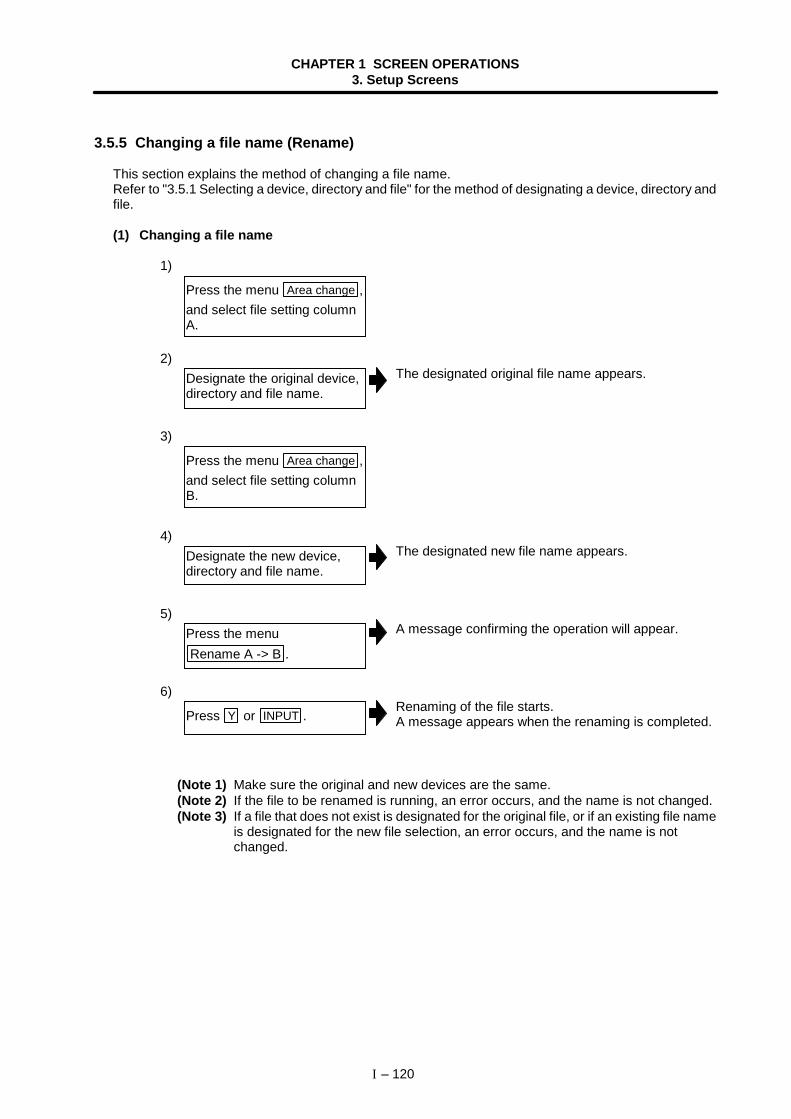
CHAPTER 1 SCREEN OPERATIONS3. Setup Screens
I – 120
3.5.5 Changing a file name (Rename)
This section explains the method of changing a file name.Refer to "3.5.1 Selecting a device, directory and file" for the method of designating a device, directory andfile.
(1) Changing a file name
1)
2)The designated original file name appears.
3)
4)The designated new file name appears.
5)A message confirming the operation will appear.
6)Renaming of the file starts.A message appears when the renaming is completed.
(Note 1) Make sure the original and new devices are the same.(Note 2) If the file to be renamed is running, an error occurs, and the name is not changed.(Note 3) If a file that does not exist is designated for the original file, or if an existing file name
is designated for the new file selection, an error occurs, and the name is notchanged.
Press the menu Area change ,and select file setting columnA.
Designate the original device,directory and file name.
Press the menu Area change ,and select file setting columnB.
Designate the new device,directory and file name.
Press the menuRename A -> B .
Press Y or INPUT .
CHAPTER 1 SCREEN OPERATIONS3. Setup Screens
I – 121
3.5.6 Creating a directory
This section explains the method of creating a directory.Refer to "3.5.1 Selecting a device, directory and file" for the method of designating a device, directory andfile.
(1) Creating a directory1)
2)The designated details appear.
3)The designated details appear.
4)The designated details appear.
5)The designated directory is created.
The directory can also be created in file setting column B.
(Note) Select HD or FLD for the device.
3.5.7 Formatting an FLDThis section explains the method for formatting an FLD.
(1) Formatting an FLD1)
A message confirming the formatting appears.
2)The FLD is formatted.A message appears when the formatting is completed.
(Note) The FLD is formatted with the 1.44MB format.
Press the menu Area change ,and select file setting columnA.
Designate the device.
Designate the directory wherethe new directory is to becreated.
Set the new directory in filesetting column A.
Press the menu Dir create .
Insert a floppy disk in the FLDdrive, and press FLD format .
Press Y or INPUT .
CHAPTER 1 SCREEN OPERATIONS3. Setup Screens
I – 122
3.5.8 List of file names
There is a directory for each type of data in the NC memory.Each directory and file name (fixed) in the NC memory is shown below.Do not change the extensions (.XXX) when storing in a device other than the NC memory.
Data type NC memory directory path Fixed file nameMachining program M01:/PRG/USER/ Program No.PRGUser macro program M01:/PRG/UMACRO/ Program No.PRGMachine maker macroprogram M01:/PRG/MMACRO/ Program No.PRG
Fixed cycle program M01:/PRG/FIX/ Program No.PRGMDI program M01:/PRG/MDI/ MDI.PRGTool offset data M01:/DAT/ TOOL.OFSWorkpiece offset data M01:/DAT/ WORK.OFSCommon variable M01:/DAT/ COMMON.VARCustom variable M01:/DAT/ CUSTOM.VAR
M01:/PRM/ PARAMET.BIN M01:/PRM/ All.PRMParameter M01:/PRM/ SYSCFG.BIN M01:/LAD/ USERPLC.LAD (SRAM) M01:/LAD/ FROM-A.LAD (FROM A)PLC program M01:/LAD/ FROM-B.LAD (FROM B)
R register data M01:/REG/ RREG.REGT register data M01:/REG/ TREG.REGC register data M01:/REG/ CREG.REG
(Note) The machine manufacturer macros are optional specifications.
CHAPTER 1 SCREEN OPERATIONS3. Setup Screens
I – 123
3.5.9 Edit lock B and C
This function prohibits editing, erasing, etc., of the machining programs B and C, and protects themachining programs.
Machining program A1 to 7999
Editing is prohibited withdata protection key (KEY3)
Machining program B(user standard subprogram)
8000 to 8999Machining program C(machine manufacturer customprogram)
9000 to 9999Machining program A
10000 to 99999999
(Note) The machine manufacturer macros (machine manufacturer custom programs) areoptional specifications.
The operations below in the Edit/MDI and the Input/Output screens are influenced by the edit lock setting.An error will result if operations that are not possible are attempted.When the edit lock is valid, processing is executed (except the edit lock target program) by theinput/output function.
: Operation possible × : Operation not possible
Edit lock B Edit lock CMachining program Machining programScreen Operation
A B C A B CSearch × × ×
Edit × × ×
Edit
MDI registration × × ×
Transfer × × ×
Compare × × ×
Copy × × ×
Condense × × ×
Merge × × ×
Rename × × ×
Input/Output
Erase × × ×
Positiondisplay2 Buffer correction × × ×
Editingprohibited byEdit lock C
Editingprohibited byEdit lock B
CHAPTER 1 SCREEN OPERATIONS3. Setup Screens
I – 124
3.5.10 Data protect keys
The data protect keys can be used to prohibit data setting and erasure, etc. The following three keys areavailable. (Their names differ according to the machine manufacturer. For further details, refer to theinstruction manual issued by the machine manufacturer.)
1) KEY 1 : For protecting all kinds of tool data, and for protecting coordinate system presettingsbased on origin set
2) KEY 2 : For protecting user parameters and common variables3) KEY 3 : For protecting machining programs
Each of the keys prohibits setting and erasing at the OFF position.
Data settingson CRT screen
KEY1
KEY2
KEY3
Tool data
User parameters
Machining programs
Data protect keys CNC data
(1) Tool data protection (KEY 1)The operations listed in Table 1 are prohibited when KEY 1 is OFF.
Table 1 Data protected by KEY1
No. Operation Screen1 Origin set Position display12 Tool offset amount setting/erasing Tool wear data/Tool data3 Tool life data setting/erasing Tool life manage4 Workpiece coordinate offset amount setting/erasing Coord offset5 Tool offset amount input/output Input/Output6 Tool data input/output Input/Output7 Tool life data input/output Input/Output8 Workpiece coordinate offset amount input/output Input/Output
(Note) If an operation shown in Table 1 is attempted when KEY1 is OFF, the message "Dataprotect" will appear.Inputting and outputting cannot be carried out on the Input/Output screen.If origin set is attempted on the Position display1 screen and the INPUT key is pressed,the origin set is not executed, and the message "Origin set not possible" appears.
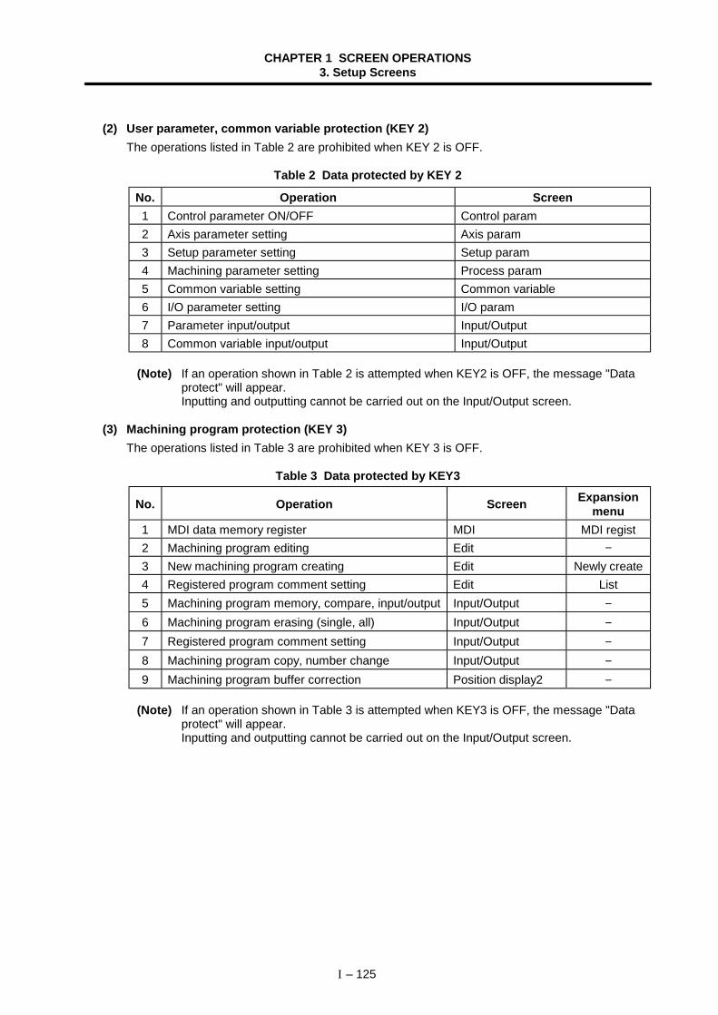
CHAPTER 1 SCREEN OPERATIONS3. Setup Screens
I – 125
(2) User parameter, common variable protection (KEY 2)The operations listed in Table 2 are prohibited when KEY 2 is OFF.
Table 2 Data protected by KEY 2
No. Operation Screen1 Control parameter ON/OFF Control param2 Axis parameter setting Axis param3 Setup parameter setting Setup param4 Machining parameter setting Process param5 Common variable setting Common variable6 I/O parameter setting I/O param7 Parameter input/output Input/Output8 Common variable input/output Input/Output
(Note) If an operation shown in Table 2 is attempted when KEY2 is OFF, the message "Dataprotect" will appear.Inputting and outputting cannot be carried out on the Input/Output screen.
(3) Machining program protection (KEY 3)The operations listed in Table 3 are prohibited when KEY 3 is OFF.
Table 3 Data protected by KEY3
No. Operation Screen Expansionmenu
1 MDI data memory register MDI MDI regist2 Machining program editing Edit −3 New machining program creating Edit Newly create4 Registered program comment setting Edit List5 Machining program memory, compare, input/output Input/Output −6 Machining program erasing (single, all) Input/Output −7 Registered program comment setting Input/Output −8 Machining program copy, number change Input/Output −9 Machining program buffer correction Position display2 −
(Note) If an operation shown in Table 3 is attempted when KEY3 is OFF, the message "Dataprotect" will appear.Inputting and outputting cannot be carried out on the Input/Output screen.
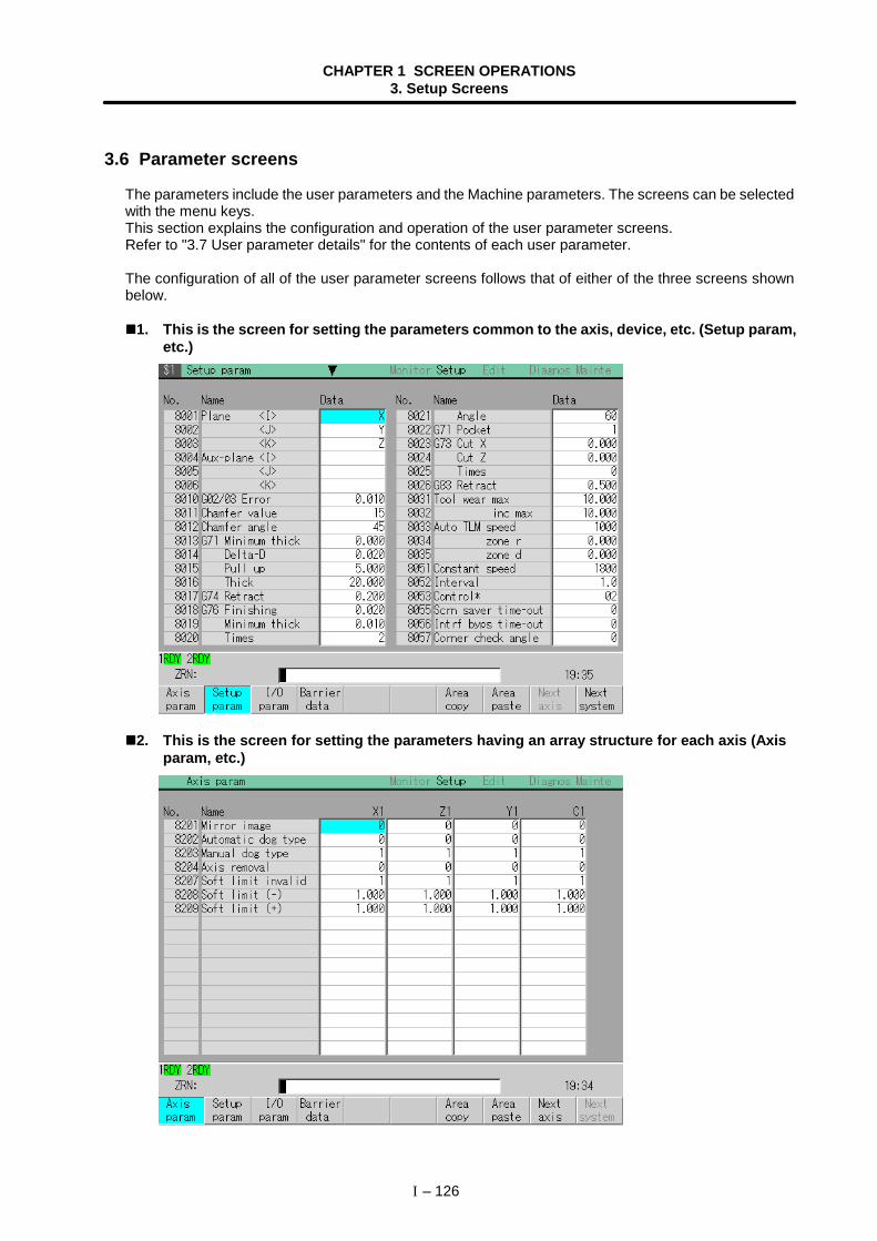
CHAPTER 1 SCREEN OPERATIONS3. Setup Screens
I – 126
3.6 Parameter screens
The parameters include the user parameters and the Machine parameters. The screens can be selectedwith the menu keys.This section explains the configuration and operation of the user parameter screens.Refer to "3.7 User parameter details" for the contents of each user parameter.
The configuration of all of the user parameter screens follows that of either of the three screens shownbelow.
1. This is the screen for setting the parameters common to the axis, device, etc. (Setup param,etc.)
2. This is the screen for setting the parameters having an array structure for each axis (Axisparam, etc.)
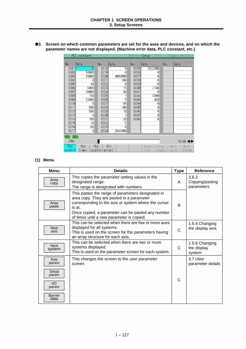
CHAPTER 1 SCREEN OPERATIONS3. Setup Screens
I – 127
3. Screen on which common parameters are set for the axes and devices, and on which theparameter names are not displayed. (Machine error data, PLC constant, etc.)
(1) Menu
Menu Details Type Reference
Areacopy
This copies the parameter setting values in thedesignated range.The range is designated with numbers.
A
Areapaste
This pastes the range of parameters designated inarea copy. They are pasted in a parametercorresponding to the axis or system where the cursoris at.Once copied, a parameter can be pasted any numberof times until a new parameter is copied.
B
3.6.2Copying/pastingparameters
Nextaxis
This can be selected when there are five or more axesdisplayed for all systems.This is used on the screen for the parameters havingan array structure for each axis.
C1.5.4 Changingthe display axis
Nextsystem
This can be selected when there are two or moresystems displayed.This is used on the parameter screen for each system.
C1.5.6 Changingthe displaysystem
Axisparam
Setupparam
I/Oparam
Barrierdata
This changes the screen to the user parameterscreen.
C
3.7 Userparameter details
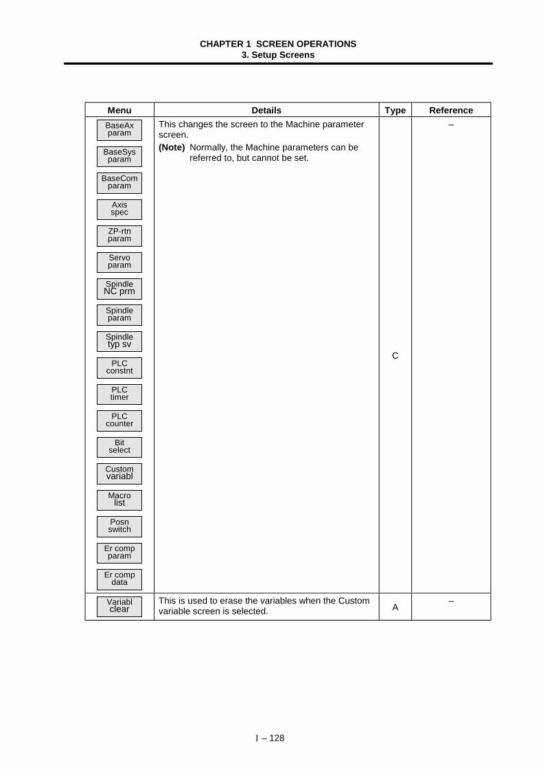
CHAPTER 1 SCREEN OPERATIONS3. Setup Screens
I – 128
Menu Details Type ReferenceBaseAxparam
BaseSysparam
BaseComparam
Axisspec
ZP-rtnparam
Servoparam
SpindleNC prm
Spindleparam
Spindletyp sv
PLCconstnt
PLCtimer
PLCcounter
Bitselect
Customvariabl
Macrolist
Posnswitch
Er compparam
Er compdata
This changes the screen to the Machine parameterscreen.(Note) Normally, the Machine parameters can be
referred to, but cannot be set.
C
–
Variablclear
This is used to erase the variables when the Customvariable screen is selected. A
–
CHAPTER 1 SCREEN OPERATIONS3. Setup Screens
I – 129
3.6.1 Setting the parameters
The method of setting the parameters is explained. For the setting range of each parameter, refer to "3.7User parameter details" and the separate instruction manual.Press the menu key to select the parameter screen, and select the data to be set with the cursor key.
(1) Setting "0" in "8201 Mirror image"
1)
2)The cursor moves to the position of the setting targetdata.
3)
The setting value appears, and the cursor moves.Parameters not having a ∗ mark are validated aftersetting.
4)Parameters with a ∗ mark are valid.
Press the menu Axis param .
Input the value. 0 INPUT
Continue setting the values.Lastly, restart the computer.
Use the ↑ , ↓ , and
keys to move the cursorto the position to be set.
CHAPTER 1 SCREEN OPERATIONS3. Setup Screens
I – 130
3.6.2 Copying/pasting parameters
The parameters can be copied and pasted to the parameters with the same number in another axis.
(1) Copying the line where the cursor is at
1)
2)The menu is highlighted.The parameter setting value at the cursor position ishighlighted.The menu highlight returns to normal.
(2) Designating and copying a range
1)
2)The menu is highlighted.
3)The copy target range is highlighted.The menu highlight returns to normal.
(Note 1) If the INPUT key is pressed without setting a number, the parameter where thecursor is at is copied.
(Note 2) The copy target range highlight returns to the normal display by pasting.
Move the cursor to theparameter to be copied.
Select area copy. Menu Area copy INPUT
Press the menu Area copy .
Designate the copy range.Format: First No./Last No. 8208/8209 INPUT
Move the cursor to the displayarea of the axes to be copied.
CHAPTER 1 SCREEN OPERATIONS3. Setup Screens
I – 131
(3) Pasting the copied data
1)
2)The menu is highlighted, and a message confirming theoperation appears.
3)The copied data is written to the parameter with thesame number as when copied, in the area where thecursor is at.The menu highlight returns to normal.
Move the cursor to the axis ordisplayed area where the datawill be pasted.
Press the menu keyArea paste .
Press the Y or INPUT key.
The copied data is not writtenin when the N key is pressed.
CHAPTER 1 SCREEN OPERATIONS3. Setup Screens
I – 132
3.7 User parameter details
Each user parameter screen can be selected from the Parameter screen. This section explains the userparameter details and setting range.Refer to "3.6 Parameter screens" for details on Parameter screen operations.
User parameter menu
Menu Details Type ReferenceAxis
paramThis changes the screen to the Axis paramscreen. C 3.7.1 Axis Parameter
Setupparam
This changes the screen to the Setupparam screen. C 3.7.2 Setup Parameter
I/Oparam
This changes the screen to the I/O paramscreen. C 3.7.3 Input/Output
ParameterBarrierdata The Barrier data screen will open. C 3.7.4 Barrier Data
(Note) The ∗ mark next to a name means that the parameter is validated after restarting.
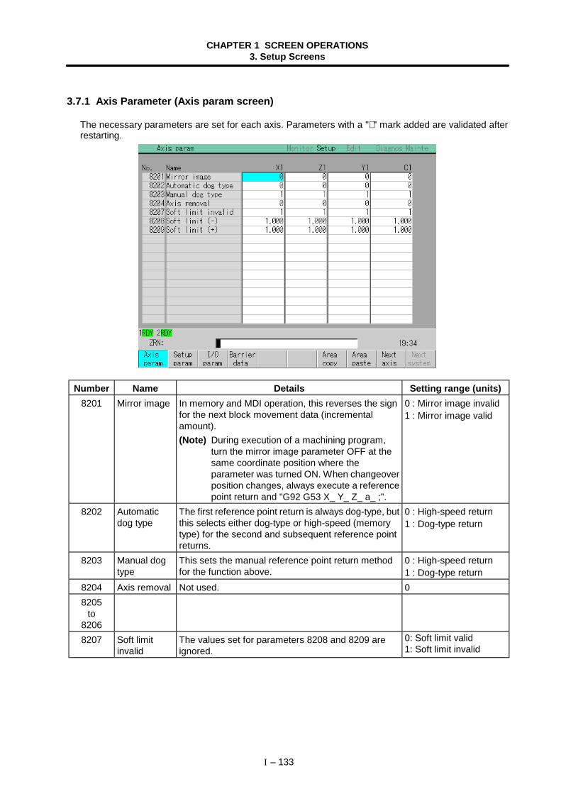
CHAPTER 1 SCREEN OPERATIONS3. Setup Screens
I – 133
3.7.1 Axis Parameter (Axis param screen)
The necessary parameters are set for each axis. Parameters with a "∗ " mark added are validated afterrestarting.
Number Name Details Setting range (units)8201 Mirror image In memory and MDI operation, this reverses the sign
for the next block movement data (incrementalamount).(Note) During execution of a machining program,
turn the mirror image parameter OFF at thesame coordinate position where theparameter was turned ON. When changeoverposition changes, always execute a referencepoint return and "G92 G53 X_ Y_ Z_ a_ ;".
0 : Mirror image invalid1 : Mirror image valid
8202 Automaticdog type
The first reference point return is always dog-type, butthis selects either dog-type or high-speed (memorytype) for the second and subsequent reference pointreturns.
0 : High-speed return1 : Dog-type return
8203 Manual dogtype
This sets the manual reference point return methodfor the function above.
0 : High-speed return1 : Dog-type return
8204 Axis removal Not used. 08205
to82068207 Soft limit
invalidThe values set for parameters 8208 and 8209 areignored.
0: Soft limit valid1: Soft limit invalid
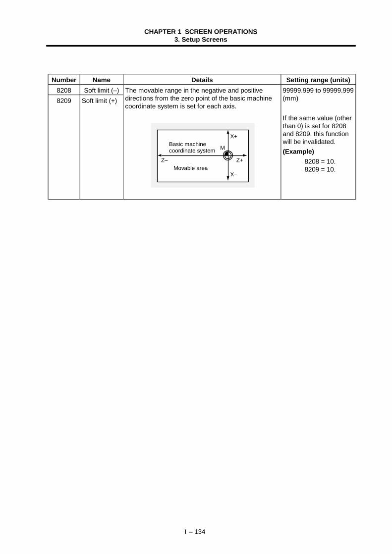
CHAPTER 1 SCREEN OPERATIONS3. Setup Screens
I – 134
Number Name Details Setting range (units)8208 Soft limit (–)8209 Soft limit (+)
The movable range in the negative and positivedirections from the zero point of the basic machinecoordinate system is set for each axis.
M
X+
Z+
X–
Z–
Basic machinecoordinate system
Movable area
99999.999 to 99999.999(mm)
If the same value (otherthan 0) is set for 8208and 8209, this functionwill be invalidated.(Example)
8208 = 10. 8209 = 10.
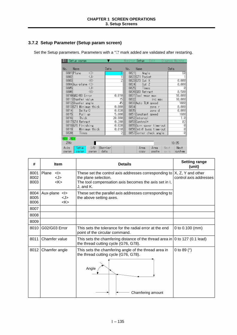
CHAPTER 1 SCREEN OPERATIONS3. Setup Screens
I – 135
3.7.2 Setup Parameter (Setup param screen)
Set the Setup parameters. Parameters with a "∗ " mark added are validated after restarting.
# Item Details Setting range(unit)
800180028003
Plane <I><J><K>
These set the control axis addresses corresponding tothe plane selection.The tool compensation axis becomes the axis set in I,J, and K.
800480058006
Aux-plane <I><J><K>
These set the parallel axis addresses corresponding tothe above setting axes.
X, Z, Y and othercontrol axis addresses
8007800880098010 G02/G03 Error This sets the tolerance for the radial error at the end
point of the circular command.0 to 0.100 (mm)
8011 Chamfer value This sets the chamfering distance of the thread area inthe thread cutting cycle (G76, G78).
0 to 127 (0.1 lead)
8012 Chamfer angle This sets the chamfering angle of the thread area inthe thread cutting cycle (G76, G78).
Chamfering amount
Angle
0 to 89 (°)
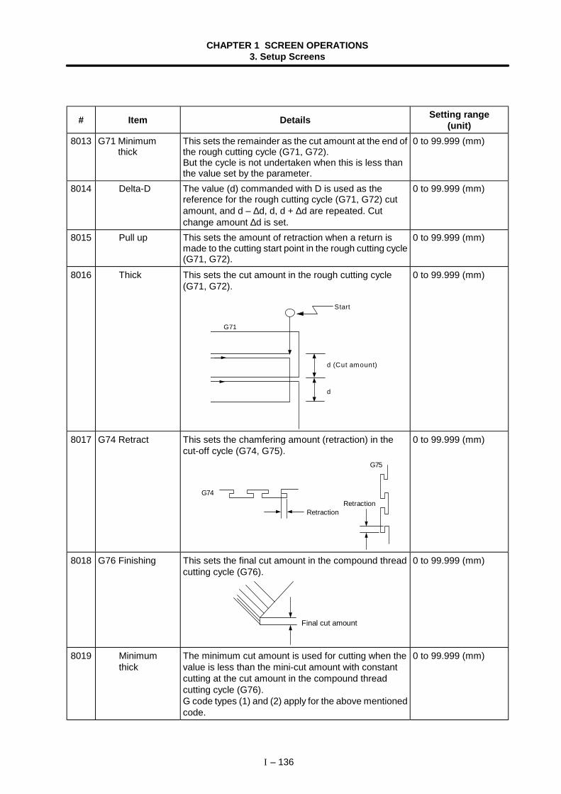
CHAPTER 1 SCREEN OPERATIONS3. Setup Screens
I – 136
# Item Details Setting range(unit)
8013 G71 Minimumthick
This sets the remainder as the cut amount at the end ofthe rough cutting cycle (G71, G72).But the cycle is not undertaken when this is less thanthe value set by the parameter.
0 to 99.999 (mm)
8014 Delta-D The value (d) commanded with D is used as thereference for the rough cutting cycle (G71, G72) cutamount, and d – ∆d, d, d + ∆d are repeated. Cutchange amount ∆d is set.
0 to 99.999 (mm)
8015 Pull up This sets the amount of retraction when a return ismade to the cutting start point in the rough cutting cycle(G71, G72).
0 to 99.999 (mm)
8016 Thick This sets the cut amount in the rough cutting cycle(G71, G72).
G71
Start
d (Cut amount)
d
0 to 99.999 (mm)
8017 G74 Retract This sets the chamfering amount (retraction) in thecut-off cycle (G74, G75).
Retraction
G74
G75
Retraction
0 to 99.999 (mm)
8018 G76 Finishing This sets the final cut amount in the compound threadcutting cycle (G76).
Final cut amount
0 to 99.999 (mm)
8019 Minimum thick
The minimum cut amount is used for cutting when thevalue is less than the mini-cut amount with constantcutting at the cut amount in the compound threadcutting cycle (G76).G code types (1) and (2) apply for the above mentionedcode.
0 to 99.999 (mm)
CHAPTER 1 SCREEN OPERATIONS3. Setup Screens
I – 137
# Item Details Setting range(unit)
8020 Times This sets the times the final cut amount (G76 Finishing)is divided in the compound thread-cutting cycle (G76).
0 to 99 (rev)
8021 Angle This sets the angle of the tool nose (thread angle) forthe G76 command.
0 to 99 (°)
8022 G71 Pocket This sets the pocket machining in the rough cuttingcycle (G71, G72) finish program when there is a cavity(pocket).
0: Pocket machining OFF1: Pocket machining ON
8023 G73 CUT X This sets the X-axis cutting allowance in the formedrough cutting cycle (G73).
0 to 99.999 (mm)
8024 CUT Z This sets the Z-axis cutting allowance for G73. 0 to 99.999 (mm)8025 Times This sets the number of G73 cutting passes. 0 to 99999 (rev)8026 G83 Retract With the second and subsequent cutting passes in the
deep-hole drilling cycle (G83). This moves the tool byrapid traverse from the position machined immediatelybefore by the amount equivalent to the setting, andthen establishes cutting feed.
0 to 99.999 (mm)
8027to
80308031 Tool wear max This sets the maximum value check data in the input
data when the tool wear data is set.0 to 99.999 (mm)
8032 inc max This sets the maximum value check data in the inputdata when the tool wear data is added.(Note) When the setting is "0", the maximum value
check is not performed.
0 to 99.999 (mm)
8033 Auto TLM speed This sets thefeedrate forautomatic toollengthmeasurement.
1 to 60000 (mm/min)
8034 zone r This sets thedistance from themeasurement pointto the decelerationstart point.
0 to 99999.999 (mm)
8035 zone d
[Automatic tool length measurement]
d
r
d
計測速度測定点
減速開始点開始点
This sets the area ofthe point where thetool should stop.
0 to 99999.999 (mm)
8051 Constant speed This sets the speed constant in the program checkoperation function.
1 to 60000
8052 Interval This sets the frame feed time (from start up to pause)in the frame feed operation function.
0 to 9.9 (s)
Decelerationstart point
Start point
Measuringspeedmeasurementpoint
CHAPTER 1 SCREEN OPERATIONS3. Setup Screens
I – 138
# Item Details Setting range(unit)
8053 Control∗ These are the parameters that select machinefunctions.
bit0: LTC (Linear type rotation axis function) 0: Invalid 1: Valid This parameter is, however, valid when the Basic common parameter "1328 sp_2 bit7" is set to 0 (common to systems). bit1: THU (High-precision thread cutting) 0: Invalid (normal thread cutting) 1: Valid This is effective when the thread cutting is valid (chamfering is invalid) during thread cutting fixed cycle (G78) or compound thread cutting Fixed cycle (G76).
bit2: SGCSelect whether to change the servo gain of therelated axis when the C axis is selected for theSpindle/C axis function.0: Do not change the position loop gain.1: Change the position loop gain.
bit4, 5: VDEG (angle between vectors)Set the angle between vectors for canceling theautomatic insertion block during the nose Rcompensation mode.If the angle between vectors is set to 0°(VDEG="00"), the automatic insertion block will bevalidated.Normally, set this to "00".
bit3, bit6, bit7: Not used. Normally set to "0".
00 to FF(hexadecimal)
8055 Scrn savertime-out
Not used. 0
8056 Intrf byps time-out This sets the time from axis stop to the time aninterference alarm is output when the interfering objectaxis movement stops during interference bypassexecution.The interference alarm will not be output when thesetting value is "0".
0 to 255 (s)
7 6 5 4 3 2 1 0VDEG SGC THU LTC
VDEGBit5 Bit4
Angle betweenvectors
0 0 0°0 1 2°1 0 4°1 1 8°
CHAPTER 1 SCREEN OPERATIONS3. Setup Screens
I – 139
# Item Details Setting range(unit)
8057 Corner checkangle
If the angle between blocks (inner angle) in automaticerror detect is less than the set value, this judges acorner, and controls the start timing of the next block.
θ
N002
N001
0 to 180 (°)
8058 Corner check width After the block being executed has begundecelerating, this begins the next block if the positionerror amount of the command end point and themachine position is less than the set value.
0 to 99.999 (mm)
8059 Angle (G1 -> G0) Not used. 0 to 180 (°)
8080 Counter selctinvld∗
This invalidates the display counter selection on thePosition display screen.
0, 1
8081 Test mode This validates the Windows key. 0, 18082 Default menu This selects the menu when the screen is selected.
0: Operation menu for each screen1: Screen selection menu
0, 1
8083 Program save type This selects the method for saving the program in theEdit screen:0: Save program being edited each time the INPUT
key is pressed.1: Save program being edited with Save file menu.
0, 1
8084 STN contrast This adjusts the contrast of STN display. 0 to 158085 Space mode in
editorThis selects the method of displaying the program onthe Edit screen:0: Display input.1: Display with inserting a space between each word.
0, 1
8086 Invalid gray menu∗ This shows or hides the menus that cannot beoperated:0: Display as gray menus.1: Do not display.
0, 1
CHAPTER 1 SCREEN OPERATIONS3. Setup Screens
I – 140
# Item Details Setting range(unit)
8090 Graphic disp scale
Set the display scale used for drawing a path on theGraphics screen.
0 to 999.999
8091 disp mode Set the display plane for drawing a path on theGraphics screen.
0 to 6
8092 coord change Designate the coordinate system used when drawing apath on the Graphics screen. 0: Basic machine coordinate system 1: Workpiece coordinate system
0, 1
8093 direct <I> Set the magnification of the display scale for the X axis(*1) drawn on the Graphics screen.When a negative value is set, the drawing direction willreverse.
–128 to 127
8094 direct <J> Set the magnification of the display scale for the Y axis(*2) drawn on the Graphics screen.When a negative value is set, the drawing direction willreverse.
–128 to 127
8095 direct <K> Set the magnification of the display scale for the Z axis(*3) drawn on the Graphics screen.When a negative value is set, the drawing direction willreverse.
–128 to 127
*1 Axis having command axis name that is the same as the axis name designated with the Setupparameter "8001 Plane <I>".
*2 Axis having command axis name that is the same as the axis name designated with the Setupparameter "8002 Plane <J>".
*3 Axis having command axis name that is the same as the axis name designated with the Setupparameter "8003 Plane <K>".
Settingvalue
Displayplane
4 YX5 YZ6 XYZ
Settingvalue
Displayplane
0 ZX1 ZY2 XZ3 ZY
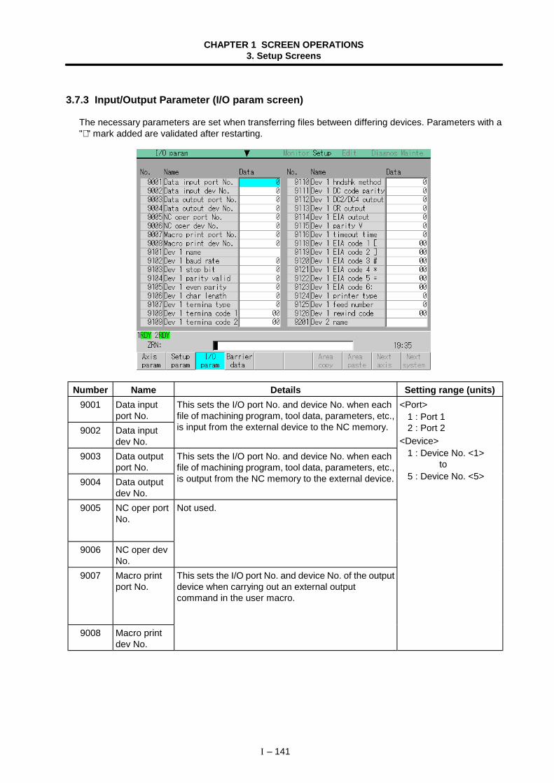
CHAPTER 1 SCREEN OPERATIONS3. Setup Screens
I – 141
3.7.3 Input/Output Parameter (I/O param screen)
The necessary parameters are set when transferring files between differing devices. Parameters with a"∗ " mark added are validated after restarting.
Number Name Details Setting range (units)9001 Data input
port No.9002 Data input
dev No.
This sets the I/O port No. and device No. when eachfile of machining program, tool data, parameters, etc.,is input from the external device to the NC memory.
9003 Data outputport No.
9004 Data outputdev No.
This sets the I/O port No. and device No. when eachfile of machining program, tool data, parameters, etc.,is output from the NC memory to the external device.
<Port>1 : Port 12 : Port 2
<Device>1 : Device No. <1>
to5 : Device No. <5>
9005 NC oper portNo.
9006 NC oper devNo.
Not used.
9007 Macro printport No.
9008 Macro printdev No.
This sets the I/O port No. and device No. of the outputdevice when carrying out an external outputcommand in the user macro.
CHAPTER 1 SCREEN OPERATIONS3. Setup Screens
I – 142
Number Name Details Setting range (units)9101 Dev 1
nameThis sets the device name corresponding to thedevice No.It is used to easily discriminate each device. (Ex.) PTR, PTP
Three characters(alphabetic, numericand symbols) or less
9102 Dev 1baud rate
This sets the data transfer speed. 300, 600, 1200, 2400,4800, 9600, 19200(bit/s)
9103 Dev 1stop bit
This sets the stop bit length in the start stop method.The bit length is set matching the specifications of theinput/output device.Refer to the item "9104 Dev 1 parity valid".
1 : 1 (bit)2 : 1.53 : 2
9104 Dev 1parity valid
This is the parameter when using a parity bit otherthan a data bit. It is set matching the specifications ofthe input/output device.
0 : No parity1 : Parity
9105 Dev 1even parity
This is the parameter that selects the odd or evenparity when the parity above is valid. This parameteris ignored when the parity is invalid. It is set matchingthe specifications of the input/output device.
0 : Odd parity1 : Even parity
9106 Dev 1char length
This sets the data bit length. The character length(data bit) is set matching the specifications of theinput/output device.Refer to the item "9104 Dev 1 parity valid".
0 : 5 bit1 : 6 bit2 : 7 bit3 : 8 bit
9107 Dev 1termina type
The code that terminates the data reading can beselected.
0 : No terminator1 : EOR or EOB2 : EOB3 : EOR4 : One random
character5 : Two random
characters9108 Dev 1
termina code1
This sets the code that terminates the reading whenthe "9107 Dev 1 termina type" setting is "4" or "5".
0 to FF (hexadecimal)
9109 Dev 1termina code2
This sets the code that terminates the reading whenthe "9107 Dev 1 termina type" setting is "5".
0 to FF (hexadecimal)
9110 Dev 1hndshkmethod
This is an RS-232C transmission control method.It is set matching the control method of theinput/output device to be connected.
1 : RTS/CTS2 : No handshake3 : DC code method
This is only valid when "2" is selected in "9110 Dev 1hndshk method".It is a parity addition for the DC code. It is set matchingthe specifications of the input/output device.
0 : No DC code parity1 : Even code parity for
DC codes
8 7 6 5 4 3 2 1
No parity (13H)DC-3
Parity (93H)
9111 Dev 1DC codeparity

CHAPTER 1 SCREEN OPERATIONS3. Setup Screens
I – 143
Number Name Details Setting range (units)9112 Dev 1
DC2/DC4output
This is set when starting the output device with a DCcode while transmitting data from the NC memory tothe output device.It is set matching the specifications of the outputdevice.
0 : DC2 invalidDC4 invalid
1 : DC2 validDC4 invalid
2 : DC2 invalidDC4 valid
3 : DC2 validDC4 valid
9113 Dev 1CR output
During output with the ISO code, this is set wheninserting a <CR> code immediately before the EOB(L/F) code.
0 : Invalid1 : Valid
9114 Dev1EIA output
During data output, this sets output by either the ISOcode or EIA code.The ISO/EIA are automatically judged during datainput.
0 : ISO output1 : EIA output
9115 Dev 1parity V
During data input into the NC memory, this is setwhen checking the parity V in one block.
0 : Invalid1 : Valid
9116 Dev 1timeout time
During data transfer, this set the timeout time thatdetects the interruption of the data transfer.An error occurs when the reading of one block oroutput time of 250 characters exceeds the designatedtime (timeout time), due to an input/output device faultor an exchange in the transmission.
The timeout time setting must be changed dependingon the transfer speed.
0 to 999 (0.1s)
9118 Dev 1EIA code 1 [
9119 Dev 1EIA code 2 ]
9120 Dev 1EIA code 3 #
9121 Dev 1EIA code 4 ∗
9122 Dev 1EIA code 5 =
9123 Dev 1EIA code 6 :
An alternate code can be designated for the codes atleft that exist in the ISO but not in the EIA.
Designate codes (odd-numbered codes) that do notduplicate preexisting EIA codes, and will not becomeparity H.
(Note) Do not designate the following codes.0 to 9, A to Z, +, −, • , ', EOR, EOB, (,),BS, TAB, SP, &, DEL, DC1 to DC4
0 to FF
9124 Dev 1printer type
This sets the type of printer to output to.(Valid for device name PTR.)
0 : Other than devicename PTR
1 : Mitsubishi printer2 : EPSON (ESC/P)
CHAPTER 1 SCREEN OPERATIONS3. Setup Screens
I – 144
Number Name Details Setting range (units)9125 Dev 1
feed numberThis designates the length of the paper tape feedsection (feed holes only) output before and after thedata when outputting the tape. The length is set as anumber of characters.The feed length is the same for both before and afterthe data.
0 to 999 (characters)
9126 Dev 1rewind code
This sets the tape rewind code. Set the rewind code ofthe tape reader device being used.(Note) The tape will not rewind when "0" is set, even
if a rewind command is issued.
0 to FF
9201to
9226
Dev 2parameters
Same as Dev 1. Same as Dev 1.
9301to
9326
Dev 3parameters
Same as Dev 1. Same as Dev 1.
9401to
9426
Dev 4parameters
Same as Dev 1. Same as Dev 1.
9501to
9526
Dev 5parameters
Same as Dev 1. Same as Dev 1.
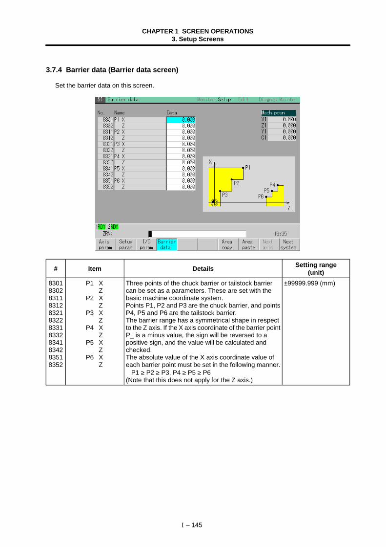
CHAPTER 1 SCREEN OPERATIONS3. Setup Screens
I – 145
3.7.4 Barrier data (Barrier data screen)
Set the barrier data on this screen.
# Item Details Setting range(unit)
830183028311831283218322833183328341834283518352
P1 XZ
P2 XZ
P3 XZ
P4 XZ
P5 XZ
P6 XZ
Three points of the chuck barrier or tailstock barriercan be set as a parameters. These are set with thebasic machine coordinate system.Points P1, P2 and P3 are the chuck barrier, and pointsP4, P5 and P6 are the tailstock barrier.The barrier range has a symmetrical shape in respectto the Z axis. If the X axis coordinate of the barrier pointP_ is a minus value, the sign will be reversed to apositive sign, and the value will be calculated andchecked.The absolute value of the X axis coordinate value ofeach barrier point must be set in the following manner. P1 ≥ P2 ≥ P3, P4 ≥ P5 ≥ P6(Note that this does not apply for the Z axis.)
±99999.999 (mm)
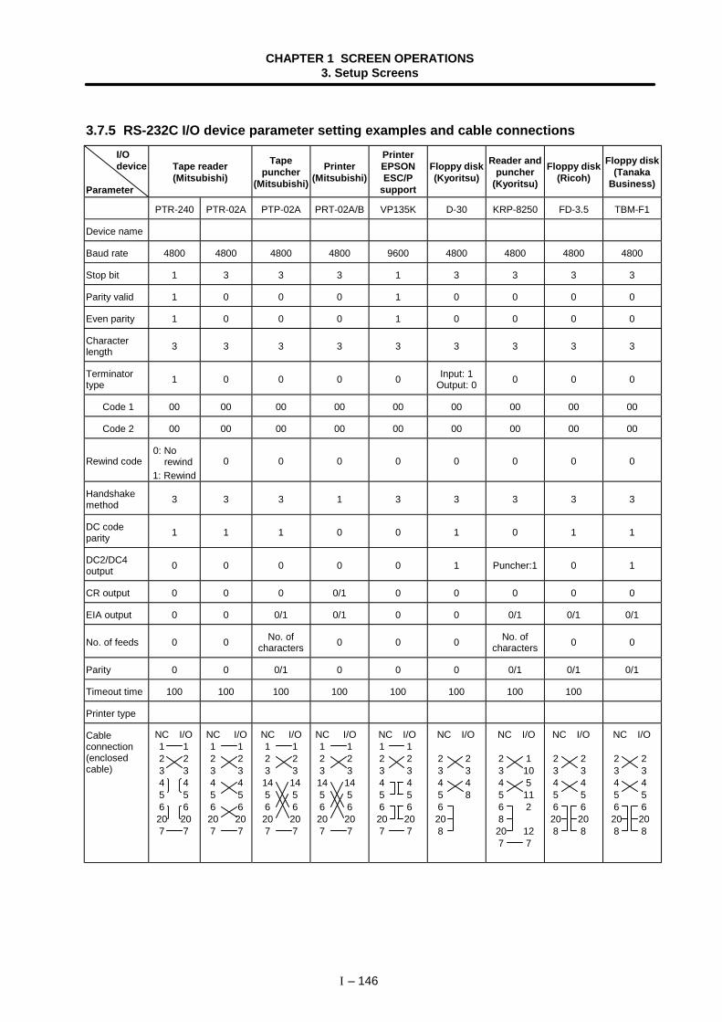
CHAPTER 1 SCREEN OPERATIONS3. Setup Screens
I – 146
3.7.5 RS-232C I/O device parameter setting examples and cable connections I/O device
Parameter
Tape reader(Mitsubishi)
Tapepuncher
(Mitsubishi)
Printer(Mitsubishi)
PrinterEPSONESC/P
support
Floppy disk(Kyoritsu)
Reader andpuncher
(Kyoritsu)
Floppy disk(Ricoh)
Floppy disk(Tanaka
Business)
PTR-240 PTR-02A PTP-02A PRT-02A/B VP135K D-30 KRP-8250 FD-3.5 TBM-F1
Device name
Baud rate 4800 4800 4800 4800 9600 4800 4800 4800 4800
Stop bit 1 3 3 3 1 3 3 3 3
Parity valid 1 0 0 0 1 0 0 0 0
Even parity 1 0 0 0 1 0 0 0 0
Characterlength 3 3 3 3 3 3 3 3 3
Terminatortype 1 0 0 0 0 Input: 1
Output: 0 0 0 0
Code 1 00 00 00 00 00 00 00 00 00
Code 2 00 00 00 00 00 00 00 00 00
Rewind code 0: No rewind1: Rewind
0 0 0 0 0 0 0 0
Handshakemethod 3 3 3 1 3 3 3 3 3
DC codeparity 1 1 1 0 0 1 0 1 1
DC2/DC4output 0 0 0 0 0 1 Puncher:1 0 1
CR output 0 0 0 0/1 0 0 0 0 0
EIA output 0 0 0/1 0/1 0 0 0/1 0/1 0/1
No. of feeds 0 0 No. ofcharacters 0 0 0 No. of
characters 0 0
Parity 0 0 0/1 0 0 0 0/1 0/1 0/1
Timeout time 100 100 100 100 100 100 100 100
Printer type
Cableconnection(enclosedcable)
NC I/O1 12 23 34 45 56 620 207 7
NC I/O1 12 23 34 45 56 620 207 7
NC I/O1 12 23 314 145 56 620 207 7
NC I/O1 12 23 314 145 56 620 207 7
NC I/O1 12 23 34 45 56 620 207 7
NC I/O
2 23 34 45 86208
NC I/O
2 13 104 55 116 2820 127 7
NC I/O
2 23 34 45 56 620 208 8
NC I/O
2 23 34 45 56 620 208 8
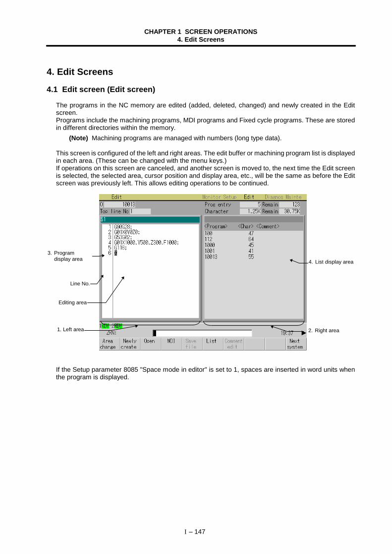
CHAPTER 1 SCREEN OPERATIONS4. Edit Screens
I – 147
4. Edit Screens
4.1 Edit screen (Edit screen)
The programs in the NC memory are edited (added, deleted, changed) and newly created in the Editscreen.Programs include the machining programs, MDI programs and Fixed cycle programs. These are storedin different directories within the memory.
(Note) Machining programs are managed with numbers (long type data).
This screen is configured of the left and right areas. The edit buffer or machining program list is displayedin each area. (These can be changed with the menu keys.)If operations on this screen are canceled, and another screen is moved to, the next time the Edit screenis selected, the selected area, cursor position and display area, etc., will be the same as before the Editscreen was previously left. This allows editing operations to be continued.
If the Setup parameter 8085 "Space mode in editor" is set to 1, spaces are inserted in word units whenthe program is displayed.
3. Programdisplay area
1. Left area 2. Right area
4. List display area
Line No.
Editing area
CHAPTER 1 SCREEN OPERATIONS4. Edit Screens
I – 148
(1) Display items
Display items Details1. Left area2. Right area
The left and right areas are used as the work areas.The area to be used is selected with the menu key Area change .
3. Programdisplay area
This area is used to edit the program (machining program, MDI program, Fixedcycle program).When editing machining program :
Select menu Open or Newly create , and designate the No.When editing MDI program :
Select menu MDI .The number does not need to be designated and searched to edit.
Fixed cycle program :After setting the Machine parameter's Basic common parameter "fix_P" to "1",select Open , and designate the No.
O 1234 ••• This displays the No. of the program currently being edited."MDI" is displayed when editing MDI data.
Top line No. This displays the No. of the head line of the program to be displayed.Editing areaand Line No.
The contents of the program being edited are displayed in the editing area.Numbers are assigned to each line of the program, and the last three digits of thatnumber are displayed. If the line is long and line is fed, a line No. will not beassigned at the head of the next line.
$ 1, 2, 3 ••• The system No. of the program displayed in the editing area is displayed.4. List display
areaWhen the menu key List is pressed, a list of the currently registered machiningprograms will appear in the area that is selected.
Prog entryand Remain
Prog entry :This displays the number of registered programs.
Remain :This displays the remaining number of programs that can be registered.
The display unit is byte, but if the displayable number of digits (7 digits) isexceeded, K (=Kbyte) or M (=Mbyte) will be added accordingly to the display.
Characterand Remain
Character :This displays the number of characters in the registered programs.
Remain :This displays the remaining number of characters that can be registered.
The numbers are indicated in byte.If the digits of the number exceed 7, the maximum digit to be displayed, indicatewith K (= Kbyte) or M (=Mbyte).
<Program><Char><Comment>
<Program> This displays the No. of the machining programs alreadyregistered.The program Nos. are displayed in order from the smallestnumber, from 1 to 99999999.
<Character> This displays the number of characters registered incorrespondence to the machining program No.
<Comment> The machining program comment is displayed. Up to 18alphanumeric characters and symbols can be used.
CHAPTER 1 SCREEN OPERATIONS4. Edit Screens
I – 149
(2) Menus
Menu Details Type Reference
Areachange
This changes the operation target area (left area/rightarea).The cursor appears in the valid area, and editing workcan be carried out.
C
1.5.2 Changingthe valid area
Newlycreate
This newly creates a program.When the program No. is set and INPUT is pressed,the program contents can be newly created.
A4.1.1 Creating anew machiningprogram
OpenThis opens an existing program to edit or refer to.When the program No. is set and INPUT is pressed,the contents of the program appear in the selectedarea, and can be edited.
A
4.1.2 Editing aprogram
MDI This edits the MDI program.When this menu key is pressed, the MDI programappears in the selected area, and can be edited.
C4.1.3 CreatingMDI data
Savefile
This saves the machining program in the NC memory.Depending on the Setup parameter "8085 Programsave type", the machining program may be saved withthe INPUT key.
B
4.1.2 Editing aprogram
ListThis displays a list of the machining programs saved inthe memory in the selected area.If the Basic common parameter "fix_P" is set to 1, a listof the Fixed cycle programs will appear.
B
4.1.2 Editing aprogram
Commentedit
This changes the program comment. (This is valid onlywhen the list is active.)The comment at the current cursor position can beedited.(Note 1) The comment of the editing program
(left/right) cannot be changed.(Note 2) The comment can only be 18 characters
long. Even if a comment exceeding 18characters is input, the 19th and followingcharacters are cut off.
A
−
Nextsystem
The contents of the system obtained by incrementingthe system No. of the program displayed in theselected area by one are displayed. Note that if thenext system's program is already displayed in thenon-active area, the system No. will be incremented bytwo.
C
−
Linedesig
When the line No. is set and the INPUT key is pressed,the program data for that No. and following appear on thescreen. The cursor moves to the set No.
A4.2.2 Designatinga random line
Linecopy
This copies a character string at a designated line(multiple lines possible). A 4.2.4 Copying/
pasting dataLinepaste
This inserts the copied line at the line before thecursor. C
Lineclear
This deletes the character string at the designated line(multiple lines possible). A 4.2.5 Deleting
data
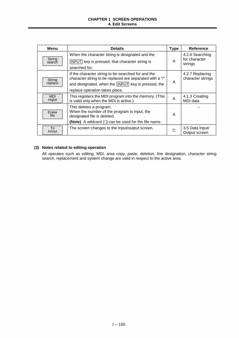
CHAPTER 1 SCREEN OPERATIONS4. Edit Screens
I – 150
Menu Details Type Reference
Stringsearch
When the character string is designated and the
INPUT key is pressed, that character string issearched for.
A4.2.6 Searchingfor characterstrings
Stringreplace
If the character string to be searched for and thecharacter string to be replaced are separated with a "/"and designated, when the INPUT key is pressed, thereplace operation takes place.
A
4.2.7 Replacingcharacter strings
MDIregist
This registers the MDI program into the memory. (Thisis valid only when the MDI is active.) A 4.1.3 Creating
MDI data
Erasefile
This deletes a program.When the number of the program is input, thedesignated file is deleted.(Note) A wildcard (∗ ) can be used for the file name.
A
−
ToIn/out
The screen changes to the Input/output screen. C 3.5 Data Input/Output screen
(3) Notes related to editing operationAll operates such as editing, MDI, area copy, paste, deletion, line designation, character stringsearch, replacement and system change are valid in respect to the active area.
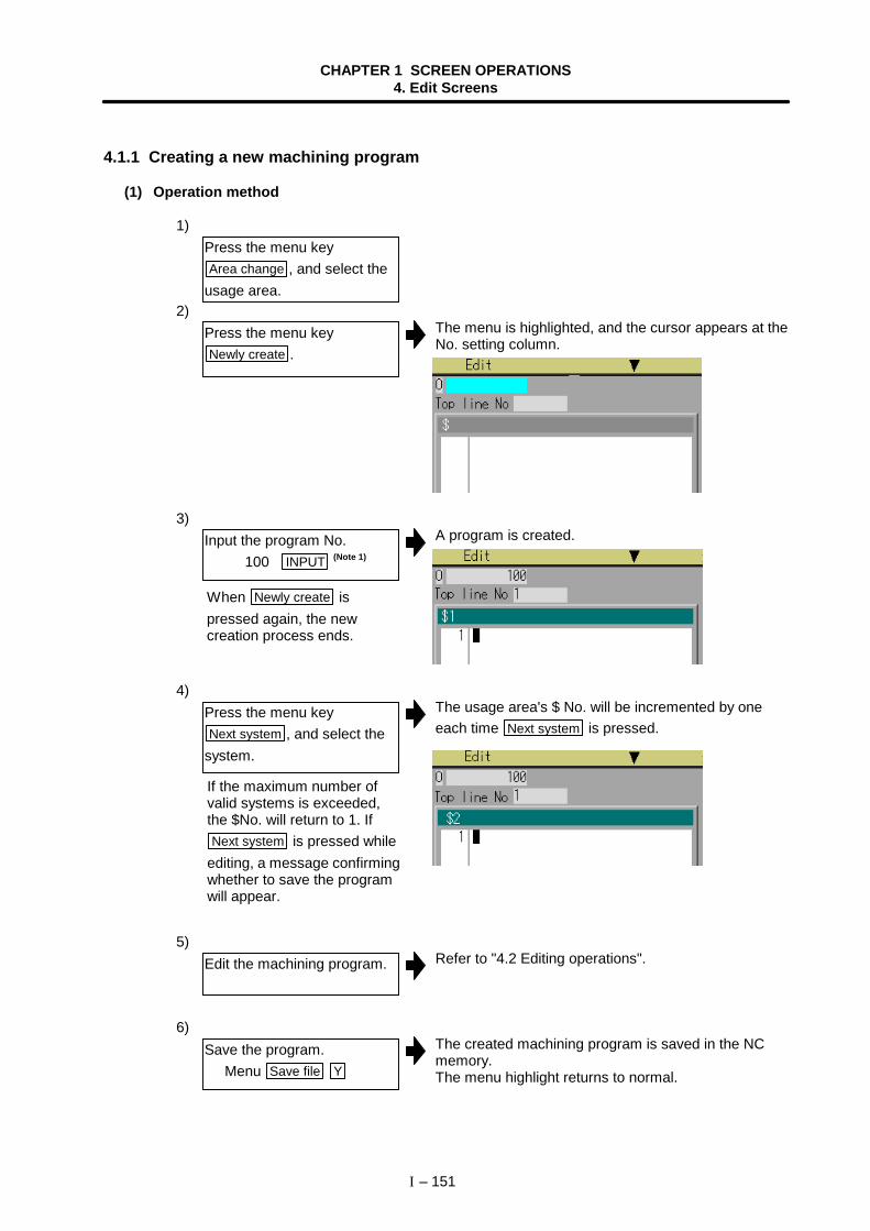
CHAPTER 1 SCREEN OPERATIONS4. Edit Screens
I – 151
4.1.1 Creating a new machining program
(1) Operation method
1)
2)The menu is highlighted, and the cursor appears at theNo. setting column.
3)A program is created.
4)The usage area's $ No. will be incremented by oneeach time Next system is pressed.
5)Refer to "4.2 Editing operations".
6)The created machining program is saved in the NCmemory.The menu highlight returns to normal.
Press the menu keyArea change , and select the
usage area.
Press the menu keyNewly create .
Input the program No. 100 INPUT (Note 1)
Press the menu keyNext system , and select the
system.
Edit the machining program.
Save the program. Menu Save file Y
When Newly create ispressed again, the newcreation process ends.
If the maximum number ofvalid systems is exceeded,the $No. will return to 1. IfNext system is pressed while
editing, a message confirmingwhether to save the programwill appear.

CHAPTER 1 SCREEN OPERATIONS4. Edit Screens
I – 152
(Note 1) An error occurs if an existing program No. is set.(Note 2) If the Setup parameter "8085 Program save type" is set to "0", the program is saved
each time the INPUT key is pressed. Thus, it is not necessary to press the Save filemenu.
(Note 3) EOR (%) is added when the program is saved for the first time.(Note 4) If the system is changed in the "Editing" state, a message confirming whether to
save the program will appear.
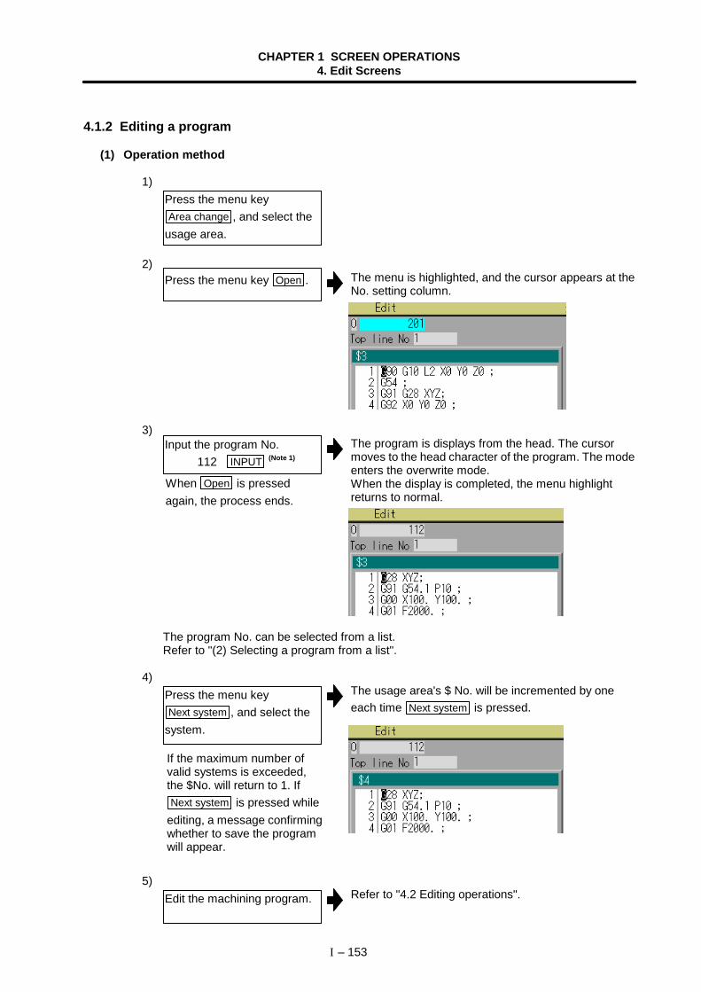
CHAPTER 1 SCREEN OPERATIONS4. Edit Screens
I – 153
4.1.2 Editing a program
(1) Operation method
1)
2)The menu is highlighted, and the cursor appears at theNo. setting column.
3)The program is displays from the head. The cursormoves to the head character of the program. The modeenters the overwrite mode.When the display is completed, the menu highlightreturns to normal.
The program No. can be selected from a list. Refer to "(2) Selecting a program from a list".
4)The usage area's $ No. will be incremented by oneeach time Next system is pressed.
5)Refer to "4.2 Editing operations".
Press the menu keyArea change , and select the
usage area.
Press the menu key Open .
Input the program No. 112 INPUT (Note 1)
Press the menu keyNext system , and select the
system.
Edit the machining program.
When Open is pressedagain, the process ends.
If the maximum number ofvalid systems is exceeded,the $No. will return to 1. IfNext system is pressed while
editing, a message confirmingwhether to save the programwill appear.
CHAPTER 1 SCREEN OPERATIONS4. Edit Screens
I – 154
6)The created machining program is saved in the NCmemory.The menu highlight returns to normal.
(Note 1) An error occurs if a nonexisting program No. is set.(Note 2) If the selected program is running, it can be displayed but not edited. An error will
occur when the data is set.(Note 3) When requesting display in a usage area, if the selected program (including system
selection) is already displayed in a non-active area, an error will occur. Note that ifthe system No. is different, the target program will be displayed without the usagearea changed. Change the system beforehand as required.
(Note 4) If the Setup parameter "8085 Program save type" is set to 0, the program is savedeach time the INPUT key is pressed. Thus, it is not necessary to press the
Save file menu.(Note 5) If the system is changed in the "Editing" state, a message confirming whether to
save the program will appear.
Save the program. Menu Save file Y (Note 4)
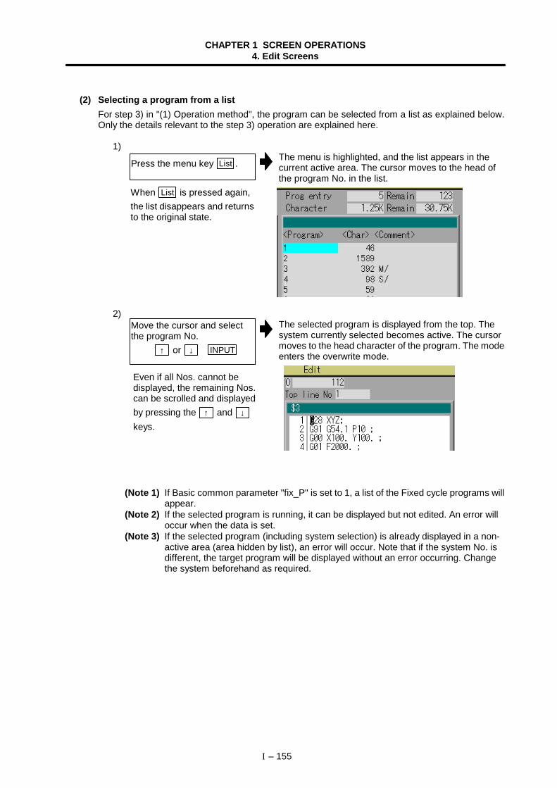
CHAPTER 1 SCREEN OPERATIONS4. Edit Screens
I – 155
(2) Selecting a program from a listFor step 3) in "(1) Operation method", the program can be selected from a list as explained below.Only the details relevant to the step 3) operation are explained here.
1)The menu is highlighted, and the list appears in thecurrent active area. The cursor moves to the head ofthe program No. in the list.
2)The selected program is displayed from the top. Thesystem currently selected becomes active. The cursormoves to the head character of the program. The modeenters the overwrite mode.
(Note 1) If Basic common parameter "fix_P" is set to 1, a list of the Fixed cycle programs willappear.
(Note 2) If the selected program is running, it can be displayed but not edited. An error willoccur when the data is set.
(Note 3) If the selected program (including system selection) is already displayed in a non-active area (area hidden by list), an error will occur. Note that if the system No. isdifferent, the target program will be displayed without an error occurring. Changethe system beforehand as required.
Press the menu key List .
Move the cursor and selectthe program No. ↑ or ↓ INPUT
When List is pressed again,the list disappears and returnsto the original state.
Even if all Nos. cannot bedisplayed, the remaining Nos.can be scrolled and displayedby pressing the ↑ and ↓
keys.
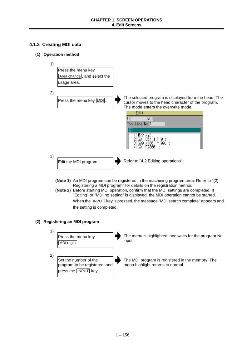
CHAPTER 1 SCREEN OPERATIONS4. Edit Screens
I – 156
4.1.3 Creating MDI data
(1) Operation method
1)
2)The selected program is displayed from the head. Thecursor moves to the head character of the program.The mode enters the overwrite mode.
3)Refer to "4.2 Editing operations".
(Note 1) An MDI program can be registered in the machining program area. Refer to "(2)Registering a MDI program" for details on the registration method.
(Note 2) Before starting MDI operation, confirm that the MDI settings are completed. If"Editing" or "MDI no setting" is displayed, the MDI operation cannot be started.When the INPUT key is pressed, the message "MDI search complete" appears andthe setting is completed.
(2) Registering an MDI program
1)The menu is highlighted, and waits for the program No.input.
2)The MDI program is registered in the memory. Themenu highlight returns to normal.
Press the menu keyArea change , and select the
usage area.
Press the menu key MDI .
Edit the MDI program.
Press the menu keyMDI regist .
Set the number of theprogram to be registered, andpress the INPUT key.
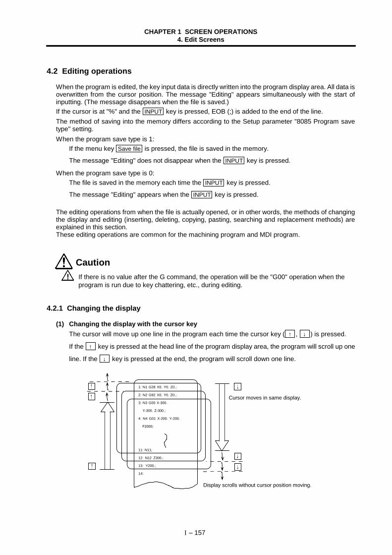
CHAPTER 1 SCREEN OPERATIONS4. Edit Screens
I – 157
4.2 Editing operations
When the program is edited, the key input data is directly written into the program display area. All data isoverwritten from the cursor position. The message "Editing" appears simultaneously with the start ofinputting. (The message disappears when the file is saved.)If the cursor is at "%" and the INPUT key is pressed, EOB (;) is added to the end of the line.The method of saving into the memory differs according to the Setup parameter "8085 Program savetype" setting.When the program save type is 1:
If the menu key Save file is pressed, the file is saved in the memory.
The message "Editing" does not disappear when the INPUT key is pressed.
When the program save type is 0:The file is saved in the memory each time the INPUT key is pressed.
The message "Editing" appears when the INPUT key is pressed.
The editing operations from when the file is actually opened, or in other words, the methods of changingthe display and editing (inserting, deleting, copying, pasting, searching and replacement methods) areexplained in this section.These editing operations are common for the machining program and MDI program.
Caution ! If there is no value after the G command, the operation will be the "G00" operation when the
program is run due to key chattering, etc., during editing.
4.2.1 Changing the display
(1) Changing the display with the cursor keyThe cursor will move up one line in the program each time the cursor key ( ↑ , ↓ ) is pressed.
If the ↑ key is pressed at the head line of the program display area, the program will scroll up one
line. If the ↓ key is pressed at the end, the program will scroll down one line.
1: N1 G28 X0. Y0. Z0.;
2: N2 G92 X0. Y0. Z0.;
3: N3 G00 X-300.
Y-300. Z-300.;
4: N4 G01 X-200. Y-200.
F2000;
11: N11;
12: N12 Z300.;
13: Y200.;
14:
Cursor moves in same display.
Display scrolls without cursor position moving.
CHAPTER 1 SCREEN OPERATIONS4. Edit Screens
I – 158
(2) Changing the display using the page changeover keys( : Previous Page, : Next Page)
This displays one page of data having the line before the current display head line as itshead line.When there is less than one page of data, a page of data will be displayed including thedata currently displayed.(The cursor moves to the last line of the screen.)This displays one page of data having the line after the current display bottom line as itsbottom line.(The cursor moves to the head line of the screen.)
(3) Displaying a random line No.If the menu key Line desig is pressed and a random line No. is input, the program contents can bedisplayed with that line at the head.
4.2.2 Rewriting data
(1) Operation method
1)
2)The message "Editing" appears when setting is started.The data is set from the position of the cursor. Data atthe area is overwritten.The cursor moves one space to the right as the data isset.
3)EOB ( ; ) is added to the set data and the data is fixed.When newly creating data, the cursor moves to thehead of the next line.When changing existing data, etc., the cursor does notmove.
(Note 1) The data is not saved in the NC memory at this point. (It will be erased when thepower is turned OFF.)To save the data in the NC memory, press Save file .
The method for saving with the INPUT key can be selected with the Setupparameter "8085 Program save type".
(Note 2) Up to 256 characters can be set in one line.
Move the cursor to theposition of the data to berewritten.
Set the data.
When one line of setting iscompleted, press the INPUTkey.
key:
key:
CHAPTER 1 SCREEN OPERATIONS4. Edit Screens
I – 159
4.2.3 Inserting data
(1) Operation method
1)
2)
The insertion mode is entered.INS appears at the top of the screen.
3)The message "Editing" appears when setting is started.The data is inserted from the position of the cursor.The cursor moves one space to the right as the data isset.
4)The set data is fixed.The cursor does not move, but if there is no EOB ( ; ) atthe end of the line, it will be added. Then, the cursormoves to the next line.The mode returns to the overwrite mode, and themessage "Editing" disappears.(The message may not disappear depending on the"Program save type".)
(Note 1) The data is not saved in the NC memory at this point. (It will be erased when thepower is turned OFF.)To save the data in the NC memory, press Save file .
The method for saving with the INPUT key can be selected with the Setupparameter "8085 Program save type".
(Note 2) Up to 256 characters can be set in one line.(Note 3) The insertion mode will be finished if a key such as DELETE , C·B ESC ,
x(INPUT), ↑ or ↓ key pressed.
Move the cursor to theposition where data is to beinserted.
Press the INSERT key.
Set the data.
When the setting iscompleted, press the INPUTkey.
CHAPTER 1 SCREEN OPERATIONS4. Edit Screens
I – 160
4.2.4 Copying/pasting data
(1) Copying a line at the cursor position
1)
2)The menu is highlighted.The entire copy target line is highlighted.
(2) Copying by designating lines (multiple lines possible)
1)The menu is highlighted.
2)The entire copy target is highlighted.The menu highlight returns to normal.
(Note 1) If INPUT key is pressed without setting a line No., the line where the cursor is at iscopied.
(Note 2) The highlight of the copy target lines disappears when editing operations areresumed.
(Note 3) If the file is edited after pressing the Line copy menu, the copied information will beerased.
(Note 4) To copy the range up to the last line of the file, designate the last line as "E". Example) From 8th line to last line → 8/E INPUT
(3) Pasting the copied data
1)
2)The copied data is inserted to the line before the cursorposition.
Move the cursor to the line tobe copied.
Press the menu keyLine copy , and press the
INPUT key.
Press the menu keyLine copy .
Designate the range to becopied.Format: first line/last line 8/10 INPUT
Move the cursor to the linewhere the data is to be pasted.
Press the menu keyLine paste .
CHAPTER 1 SCREEN OPERATIONS4. Edit Screens
I – 161
4.2.5 Deleting data
(1) Deleting one character
1)
2)The character at the cursor position is deleted. Thedata following the cursor position moves one to the left.When this key is held down, the characters can bedeleted one at a time.
(2) Deleting the line at the cursor position
1)
2)The menu is highlighted.All lines targeted for deletion are highlighted.A message confirming the deletion appears.
3)The highlighted lines are deleted, and the menuhighlight returns to normal. The lines following thecursor position are shifted upward.The cursor position and head line No. do not change.
Move the cursor to thecharacter to be deleted.
Press the DELETE key.
Move the cursor to the line tobe deleted.
Delete the line. Menu Line clear INPUT
Press the Y or INPUT key.
To cancel the deletion, pressthe N key.
CHAPTER 1 SCREEN OPERATIONS4. Edit Screens
I – 162
(3) Deleting designated lines (multiple lines possible)
1)
2)The entire deletion target is highlighted.A message confirming the deletion appears.
3)The highlighted range is deleted, and the menuhighlight returns to normal. The lines following thecursor position are shifted upward.The cursor position and head line No. do not change.
(Note 1) If the INPUT key is pressed without setting a line No., the line where the cursor is atis deleted.
(Note 2) To delete the range up to the last line of the file, designate the last line as "E". Example) From 8th line to last line → 8/E INPUT
(4) Deleting several lines displayed on a screen (one screen of data)
One screen of editing data (machining program) isdeleted.
Press the menu keyLine clear .
Designate the range to becopied.Format: first line/last line 8/10 INPUT
Press the Y or INPUT key.
Press SHIFT + C·B ESC .
To cancel the deletion, pressthe N key.
The menu is highlighted.The menu is highlighted.
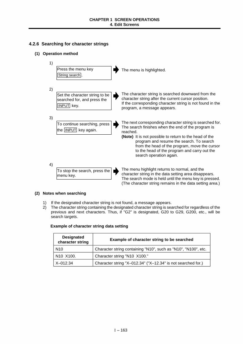
CHAPTER 1 SCREEN OPERATIONS4. Edit Screens
I – 163
4.2.6 Searching for character strings
(1) Operation method
1)
The menu is highlighted.
2)The character string is searched downward from thecharacter string after the current cursor position.If the corresponding character string is not found in theprogram, a message appears.
3)The next corresponding character string is searched for.The search finishes when the end of the program isreached.(Note) It is not possible to return to the head of the
program and resume the search. To searchfrom the head of the program, move the cursorto the head of the program and carry out thesearch operation again.
4)The menu highlight returns to normal, and thecharacter string in the data setting area disappears.The search mode is held until the menu key is pressed.(The character string remains in the data setting area.)
(2) Notes when searching
1) If the designated character string is not found, a message appears.2) The character string containing the designated character string is searched for regardless of the
previous and next characters. Thus, if "G2" is designated, G20 to G29, G200, etc., will besearch targets.
Example of character string data setting
Designatedcharacter string Example of character string to be searched
N10 Character string containing "N10", such as "N10", "N100", etc.
N10 X100. Character string "N10 X100."
X–012.34 Character string "X–012.34" ("X–12.34" is not searched for.)
Press the menu keyString search .
Set the character string to besearched for, and press theINPUT key.
To continue searching, pressthe INPUT key again.
To stop the search, press themenu key.
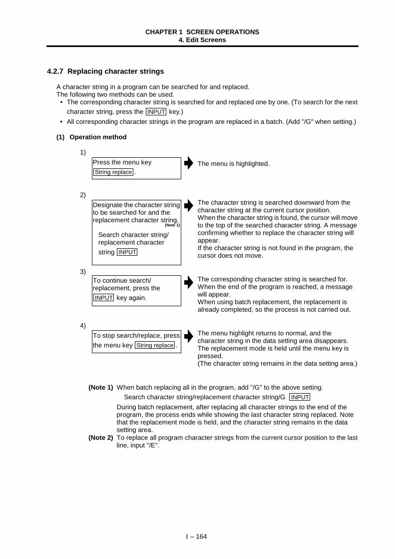
CHAPTER 1 SCREEN OPERATIONS4. Edit Screens
I – 164
4.2.7 Replacing character strings
A character string in a program can be searched for and replaced.The following two methods can be used.
• The corresponding character string is searched for and replaced one by one. (To search for the nextcharacter string, press the INPUT key.)
• All corresponding character strings in the program are replaced in a batch. (Add "/G" when setting.)
(1) Operation method
1)
The menu is highlighted.
2)The character string is searched downward from thecharacter string at the current cursor position.When the character string is found, the cursor will moveto the top of the searched character string. A messageconfirming whether to replace the character string willappear.If the character string is not found in the program, thecursor does not move.
3)The corresponding character string is searched for.When the end of the program is reached, a messagewill appear.When using batch replacement, the replacement isalready completed, so the process is not carried out.
4)The menu highlight returns to normal, and thecharacter string in the data setting area disappears.The replacement mode is held until the menu key ispressed.(The character string remains in the data setting area.)
(Note 1) When batch replacing all in the program, add "/G" to the above setting. Search character string/replacement character string/G INPUTDuring batch replacement, after replacing all character strings to the end of theprogram, the process ends while showing the last character string replaced. Notethat the replacement mode is held, and the character string remains in the datasetting area.
(Note 2) To replace all program character strings from the current cursor position to the lastline, input "/E".
Press the menu keyString replace .
Designate the character stringto be searched for and thereplacement character string.
(Note 1)
Search character string/ replacement character string INPUT
To continue search/replacement, press theINPUT key again.
To stop search/replace, pressthe menu key String replace .
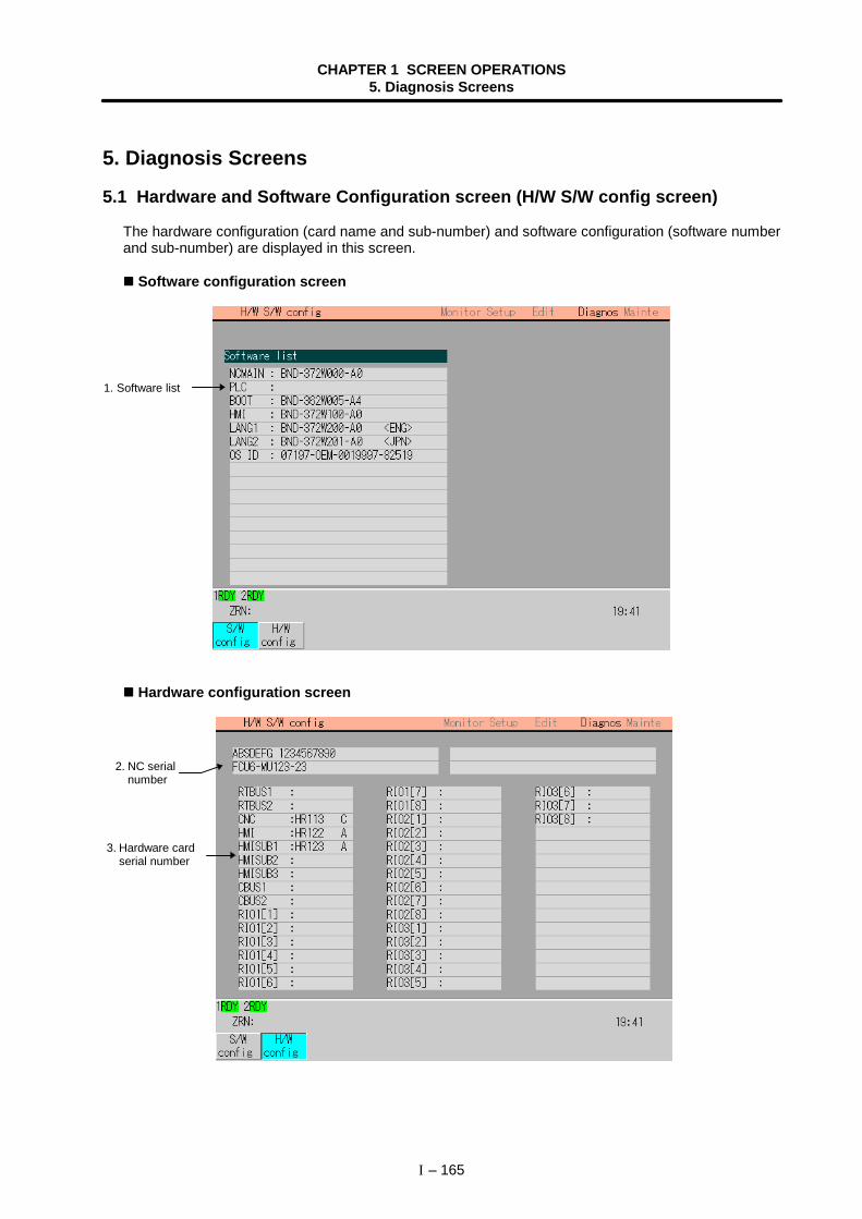
CHAPTER 1 SCREEN OPERATIONS5. Diagnosis Screens
I – 165
5. Diagnosis Screens
5.1 Hardware and Software Configuration screen (H/W S/W config screen)
The hardware configuration (card name and sub-number) and software configuration (software numberand sub-number) are displayed in this screen.
Software configuration screen
Hardware configuration screen
1. Software list
3. Hardware cardserial number
2. NC serialnumber
CHAPTER 1 SCREEN OPERATIONS5. Diagnosis Screens
I – 166
(1) Display items
Display item Details1. Software list This displays a list of the software being used.
2. NC serial No. This displays the NC serial No., NC type and unit type.
3. Hardware card serial No. This displays the serial No. of each hardware card.
(2) Menus
Menu Details TypeS/W
config This displays the software list. (Previous page, upper screen) C
H/Wconfig This displays the hardware list. (Previous page, lower screen) C
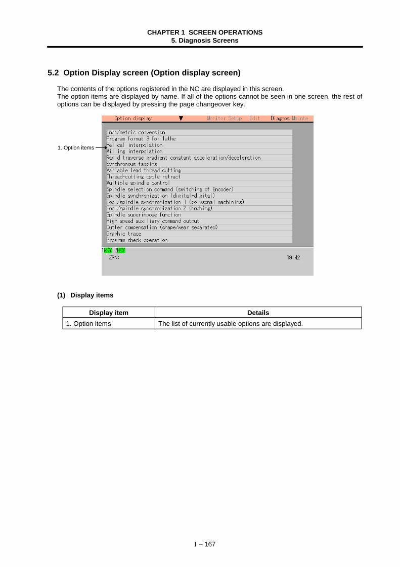
CHAPTER 1 SCREEN OPERATIONS5. Diagnosis Screens
I – 167
5.2 Option Display screen (Option display screen)
The contents of the options registered in the NC are displayed in this screen.The option items are displayed by name. If all of the options cannot be seen in one screen, the rest ofoptions can be displayed by pressing the page changeover key.
(1) Display items
Display item Details1. Option items The list of currently usable options are displayed.
1. Option items
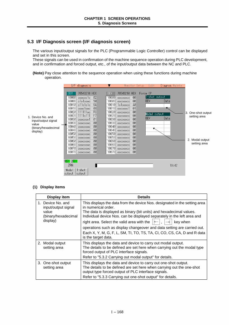
CHAPTER 1 SCREEN OPERATIONS5. Diagnosis Screens
I – 168
5.3 I/F Diagnosis screen (I/F diagnosis screen)
The various input/output signals for the PLC (Programmable Logic Controller) control can be displayedand set in this screen.These signals can be used in confirmation of the machine sequence operation during PLC development,and in confirmation and forced output, etc., of the input/output data between the NC and PLC.
(Note) Pay close attention to the sequence operation when using these functions during machineoperation.
(1) Display items
Display item Details1. Device No. and
input/output signalvalue(binary/hexadecimaldisplay)
This displays the data from the device Nos. designated in the setting areain numerical order.The data is displayed as binary (bit units) and hexadecimal values.Individual device Nos. can be displayed separately in the left area andright area. Select the valid area with the , key whenoperations such as display changeover and data setting are carried out.Each X, Y, M, G, F, L, SM, TI, TO, TS, TA, CI, CO, CS, CA, D and R datais the target data.
2. Modal outputsetting area
This displays the data and device to carry out modal output.The details to be defined are set here when carrying out the modal typeforced output of PLC interface signals.Refer to "5.3.2 Carrying out modal output" for details.
3. One-shot outputsetting area
This displays the data and device to carry out one-shot output.The details to be defined are set here when carrying out the one-shotoutput type forced output of PLC interface signals.Refer to "5.3.3 Carrying out one-shot output" for details.
1. Device No. andinput/output signalvalue(binary/hexadecimaldisplay)
2. Modal outputsetting area
3. One-shot outputsetting area
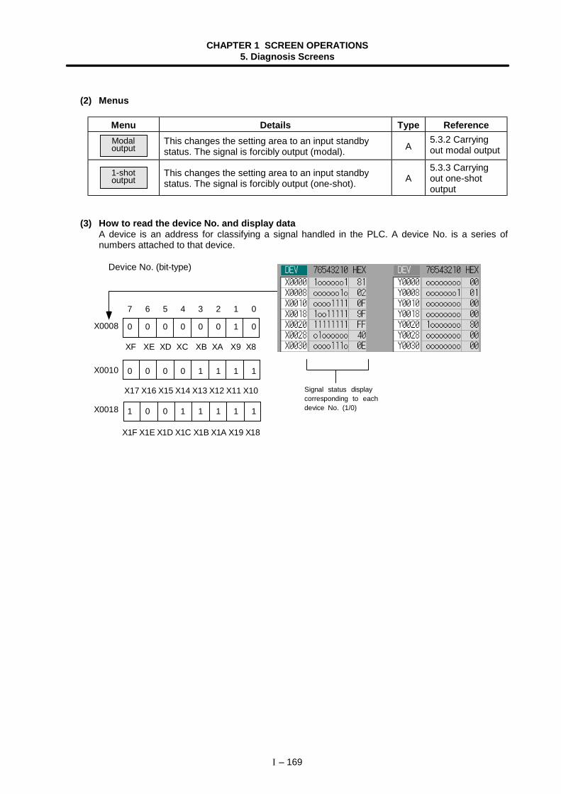
CHAPTER 1 SCREEN OPERATIONS5. Diagnosis Screens
I – 169
(2) Menus
Menu Details Type ReferenceModaloutput
This changes the setting area to an input standbystatus. The signal is forcibly output (modal). A
5.3.2 Carryingout modal output
1-shotoutput
This changes the setting area to an input standbystatus. The signal is forcibly output (one-shot). A
5.3.3 Carryingout one-shotoutput
(3) How to read the device No. and display dataA device is an address for classifying a signal handled in the PLC. A device No. is a series ofnumbers attached to that device.
7 6 5 4 3 2 1 0
0 0 0 0 0 0 1 0
XF XE XD XC XB XA X9 X8
0 0 0 0 1 1 1 1
1 0 0 1 1 1 1 1
X0008
X0010
X0018
Signal status displaycorresponding to eachdevice No. (1/0)
Device No. (bit-type)
X17 X16 X15 X14 X13 X12 X11 X10
X1F X1E X1D X1C X1B X1A X19 X18
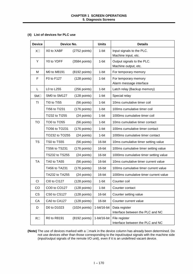
CHAPTER 1 SCREEN OPERATIONS5. Diagnosis Screens
I – 170
(4) List of devices for PLC use
Device Device No. Units Details
X∗ X0 to XABF (2752 points) 1-bit Input signals to the PLC.Machine input, etc.
Y Y0 to YDFF (3584 points) 1-bit Output signals to the PLC.Machine output, etc.
M M0 to M8191 (8192 points) 1-bit For temporary memory
F F0 to F127 (128 points) 1-bit For temporary memoryAlarm message interface
L L0 to L255 (256 points) 1-bit Latch relay (Backup memory)
SM∗ SM0 to SM127 (128 points) 1-bit Special relay
TI TI0 to TI55 (56 points) 1-bit 10ms cumulative timer coil
TI56 to TI231 (176 points) 1-bit 100ms cumulative timer coil
TI232 to TI255 (24 points) 1-bit 1000ms cumulative timer coil
TO TO0 to TO55 (56 points) 1-bit 10ms cumulative timer contact
TO56 to TO231 (176 points) 1-bit 100ms cumulative timer contact
TO232 to TO255 (24 points) 1-bit 1000ms cumulative timer contact
TS TS0 to TS55 (56 points) 16-bit 10ms cumulative timer setting value
TS56 to TS231 (176 points) 16-bit 100ms cumulative timer setting value
TS232 to TS255 (24 points) 16-bit 1000ms cumulative timer setting value
TA TA0 to TA55 (56 points) 16-bit 10ms cumulative timer current value
TA56 to TA231 (176 points) 16-bit 100ms cumulative timer current value
TA232 to TA255 (24 points) 16-bit 1000ms cumulative timer current value
CI CI0 to CI127 (128 points) 1-bit Counter coil
CO CO0 to CO127 (128 points) 1-bit Counter contact
CS CS0 to CS127 (128 points) 16-bit Counter setting value
CA CA0 to CA127 (128 points) 16-bit Counter current value
D D0 to D1023 (1024 points) 1-bit/16-bit Data registerInterface between the PLC and NC
R∗ R0 to R8191 (8192 points) 1-bit/16-bit File registerInterface between the PLC and NC
(Note) The use of devices marked with a ∗ mark in the device column has already been determined. Donot use devices other than those corresponding to the input/output signals with the machine side(input/output signals of the remote I/O unit), even if it is an undefined vacant device.
CHAPTER 1 SCREEN OPERATIONS5. Diagnosis Screens
I – 171
5.3.1 Displaying the PLC device data
The various status signals and register data used in the PLC can be monitored and displayed.When this screen is first selected, the respective 16-byte amounts of input/output data are displayedfrom device "X0000" on the left display area, and from device "Y0000" on the right side.This screen constantly monitors and displays the PLC signal statuses. Consequently, when signals arechanged in the PLC, the display is changed according to the changes.Note that because time differences occur between the PLC signal change and the signal display, theremay be a delay in the display. The machine may also not be able to correspond to extremely brief signalchanges.
(1) Displaying the data of a random device No. "X0020"
1)
2)The device "X0020" data appears at the head of thevalid display area.
(Note) When setting the device No., an error will occur if a number exceeding thespecifications or an illegal address is set.
(2) Changing the display with the page keysThe valid area device Nos. change in page units when / is pressed.
1)The data is displayed from the next number currentlydisplayed.
Press the menu Tab key ,, and select the
area to display the data.
Set the device No. (X0020),and press the INPUT key.
Press the key.
CHAPTER 1 SCREEN OPERATIONS5. Diagnosis Screens
I – 172
5.3.2 Carrying out modal output
Modal type forced output of PLC interface signals is carried out. Once set, this data is held until canceled,the power is turned ON/OFF, or other data is overwritten. There are four sets of devices that modallyoutput. If this number is exceeded, the previously existing data is overwritten.
(1) Menus used in modal output
Menu Details Type Reference
Modalall clr
Modal output of all devices in the modal output area iscanceled in a batch.The canceled data is erased from this area.
C(3) Cancelingmodal output in abatch
Modalsgl clr
Modal output of the device at the position of the cursorin the modal output area is independently canceled.The canceled data is erased from this area.
C(4) Independentlycanceling modaloutput
(2) Modally outputting data "1" to device "X0048"1)
The modal output mode is entered, and the cursorappears at the modal output area.
2)
3)Modal output is executed, and the cursor disappears.The data that was in the cursor position is overwrittenby the input data, and is invalidated.The modal output mode is canceled by pressing the
key.
(Note) The data of the modally output device is displayed in order in the selected area.This modal output is held until the output is canceled or the power is turned OFF.
Press the menu keyModal output .
Using the ↑ and ↓ keys,move the cursor to the settingposition.
Set the device and data, andpress the INPUT key.
X0048/1 INPUT
CHAPTER 1 SCREEN OPERATIONS5. Diagnosis Screens
I – 173
(3) Canceling modal output in a batch1)
The modal output mode is entered, and the cursorappears at the modal output area.
2)Modal output of all data is canceled. The modal outputareas "DEV" and "Data" are all cleared.The modal output mode is canceled by pressing the
key.
(4) Independently canceling modal output1)
The modal output mode is entered, and the cursorappears at the modal output area.
2)
3)The data that was in the cursor position is canceledfrom modal output. The "DEV" and "Data" columnsbecome blank.The modal output mode is canceled by pressing the
key.
Caution
! Pay close attention to the sequence operation when carrying out forced data setting (forcedoutput) in the I/F diagnosis screen.
Press the menu keyModal output .
Press the menu keyModal all clr .
Press the menu keyModal output .
Using the ↑ and ↓ keys,move the cursor to the data tobe canceled.
Press the menu keyModal sgl clr .
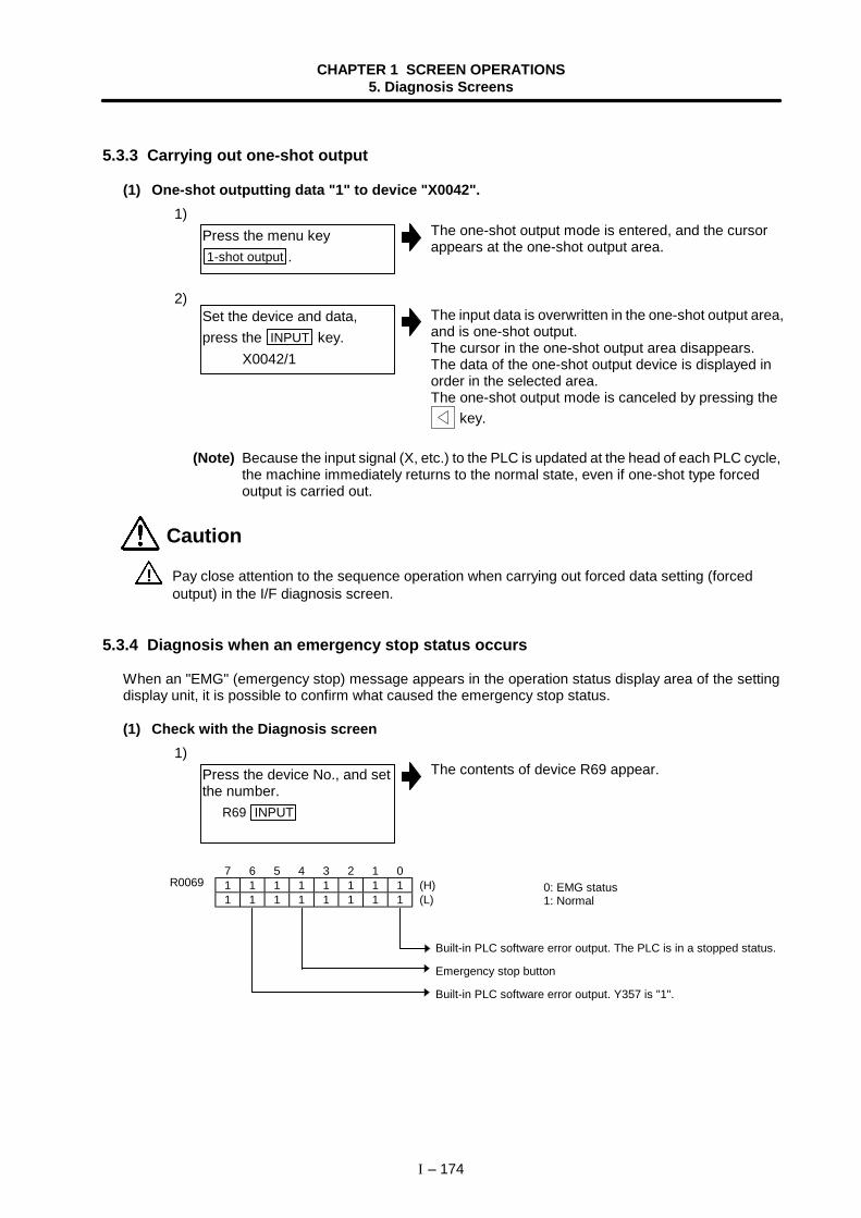
CHAPTER 1 SCREEN OPERATIONS5. Diagnosis Screens
I – 174
5.3.3 Carrying out one-shot output
(1) One-shot outputting data "1" to device "X0042".1)
The one-shot output mode is entered, and the cursorappears at the one-shot output area.
2)The input data is overwritten in the one-shot output area,and is one-shot output.The cursor in the one-shot output area disappears.The data of the one-shot output device is displayed inorder in the selected area.The one-shot output mode is canceled by pressing the
key.
(Note) Because the input signal (X, etc.) to the PLC is updated at the head of each PLC cycle,the machine immediately returns to the normal state, even if one-shot type forcedoutput is carried out.
Caution
! Pay close attention to the sequence operation when carrying out forced data setting (forcedoutput) in the I/F diagnosis screen.
5.3.4 Diagnosis when an emergency stop status occurs
When an "EMG" (emergency stop) message appears in the operation status display area of the settingdisplay unit, it is possible to confirm what caused the emergency stop status.
(1) Check with the Diagnosis screen1)
The contents of device R69 appear.
7 6 5 4 3 2 1 01 1 1 1 1 1 1 1 (H)1 1 1 1 1 1 1 1 (L)
Press the menu key1-shot output .
Set the device and data,press the INPUT key. X0042/1
Press the device No., and setthe number. R69 INPUT
R0069 0: EMG status1: Normal
Built-in PLC software error output. The PLC is in a stopped status.
Emergency stop button
Built-in PLC software error output. Y357 is "1".
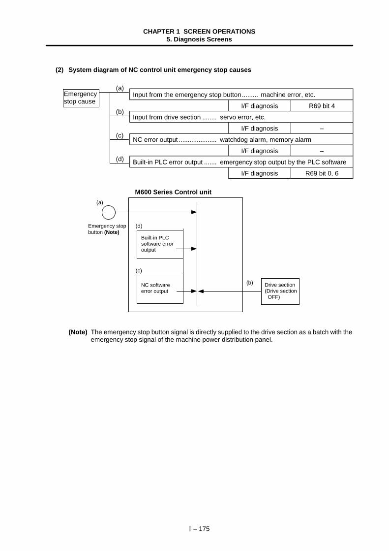
CHAPTER 1 SCREEN OPERATIONS5. Diagnosis Screens
I – 175
(2) System diagram of NC control unit emergency stop causes
Input from the emergency stop button......... machine error, etc.
I/F diagnosis R69 bit 4
Input from drive section ........ servo error, etc.
I/F diagnosis –
NC error output ..................... watchdog alarm, memory alarm
I/F diagnosis –
Built-in PLC error output ....... emergency stop output by the PLC software
I/F diagnosis R69 bit 0, 6
(a)
(b)
(d)
(c)
(Note) The emergency stop button signal is directly supplied to the drive section as a batch with theemergency stop signal of the machine power distribution panel.
Emergencystop cause
(a)
(b)
(c)
(d)
M600 Series Control unit
Emergency stopbutton (Note)
Built-in PLCsoftware erroroutput
NC softwareerror output
Drive section(Drive section OFF)
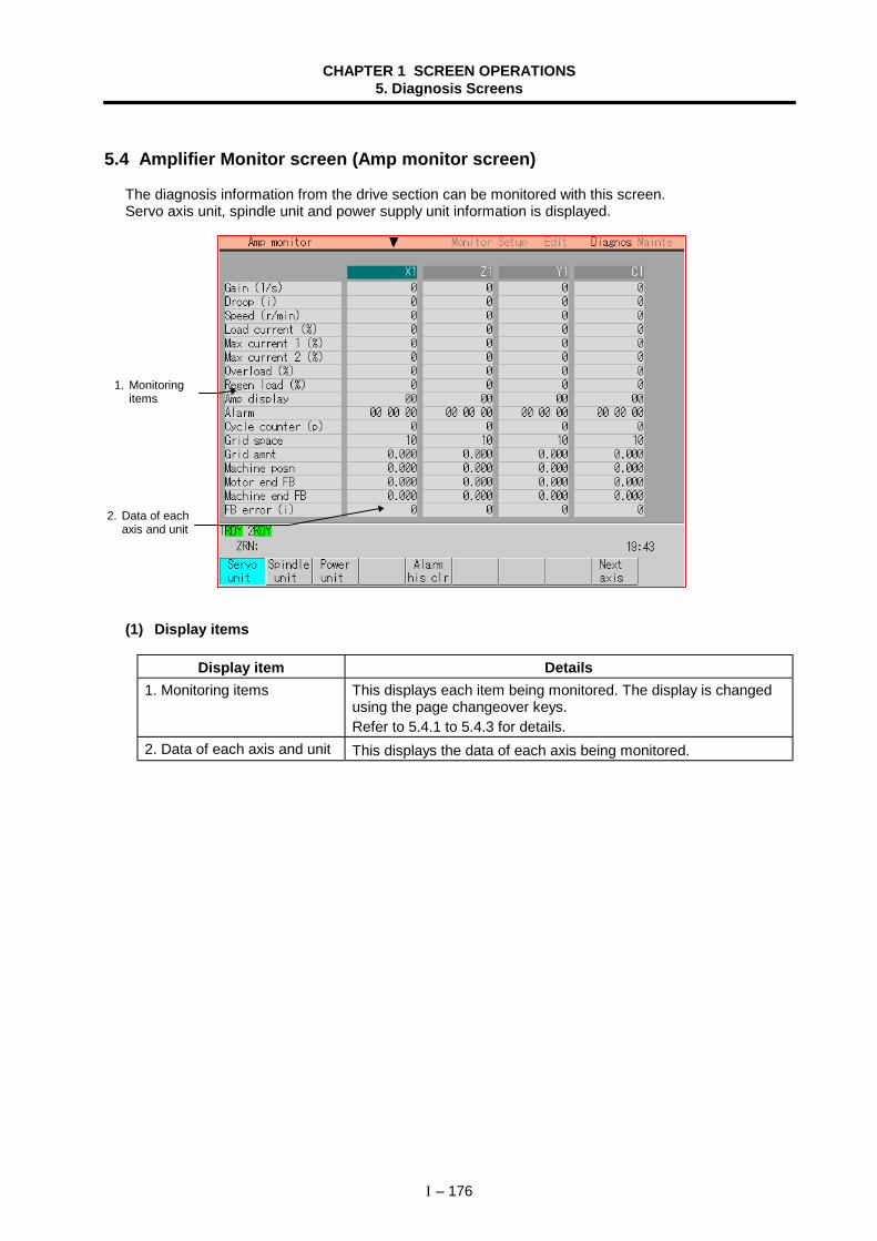
CHAPTER 1 SCREEN OPERATIONS5. Diagnosis Screens
I – 176
5.4 Amplifier Monitor screen (Amp monitor screen)
The diagnosis information from the drive section can be monitored with this screen.Servo axis unit, spindle unit and power supply unit information is displayed.
(1) Display items
Display item Details1. Monitoring items This displays each item being monitored. The display is changed
using the page changeover keys.Refer to 5.4.1 to 5.4.3 for details.
2. Data of each axis and unit This displays the data of each axis being monitored.
1. Monitoringitems
2. Data of eachaxis and unit
CHAPTER 1 SCREEN OPERATIONS5. Diagnosis Screens
I – 177
(2) Menus
Menu Details Type ReferenceServounit
This displays the diagnosis information of the servounit in the data display area. C
5.4.1 Servo axisunit display items
Spindleunit
This displays the diagnosis information of the spindleunit in the data display area. C
5.4.2 Spindle unitdisplay items
Powerunit
This displays the diagnosis information of the powerunit in the data display area. C
5.4.3 Displayitems for thepower supply unit
Alarmhis clr
This clears the diagnosis information alarm history.B
5.4.4 Clearingthe alarm history
Nextaxis
This displays the data for the next four axes.(Note) The menu appears and operation is possible
only when diagnosis information for five ormore axes is displayed.
C
−
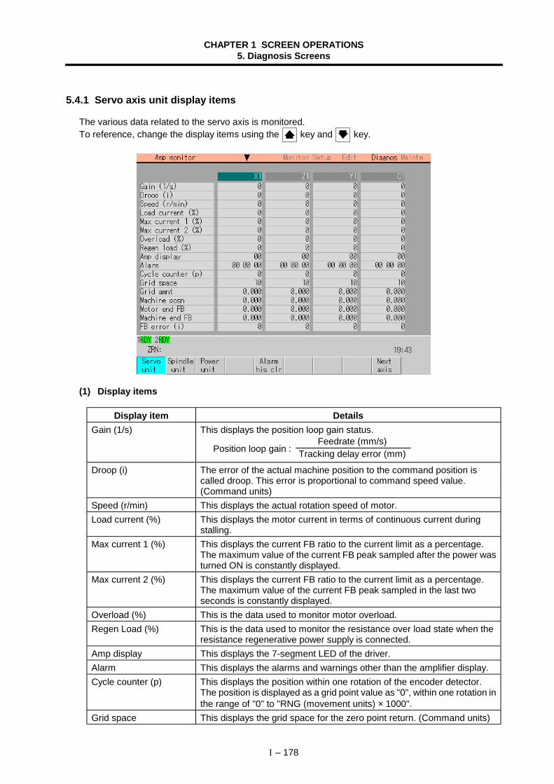
CHAPTER 1 SCREEN OPERATIONS5. Diagnosis Screens
I – 178
5.4.1 Servo axis unit display items
The various data related to the servo axis is monitored.To reference, change the display items using the key and key.
(1) Display items
Display item DetailsGain (1/s) This displays the position loop gain status.
Position loop gain : Feedrate (mm/s)
Tracking delay error (mm)
Droop (i) The error of the actual machine position to the command position iscalled droop. This error is proportional to command speed value.(Command units)
Speed (r/min) This displays the actual rotation speed of motor.Load current (%) This displays the motor current in terms of continuous current during
stalling.Max current 1 (%) This displays the current FB ratio to the current limit as a percentage.
The maximum value of the current FB peak sampled after the power wasturned ON is constantly displayed.
Max current 2 (%) This displays the current FB ratio to the current limit as a percentage.The maximum value of the current FB peak sampled in the last twoseconds is constantly displayed.
Overload (%) This is the data used to monitor motor overload.Regen Load (%) This is the data used to monitor the resistance over load state when the
resistance regenerative power supply is connected.Amp display This displays the 7-segment LED of the driver.Alarm This displays the alarms and warnings other than the amplifier display.Cycle counter (p) This displays the position within one rotation of the encoder detector.
The position is displayed as a grid point value as "0", within one rotation inthe range of "0" to "RNG (movement units) × 1000".
Grid space This displays the grid space for the zero point return. (Command units)
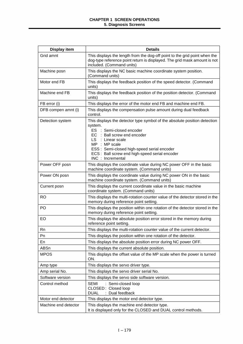
CHAPTER 1 SCREEN OPERATIONS5. Diagnosis Screens
I – 179
Display item DetailsGrid amnt This displays the length from the dog-off point to the grid point when the
dog-type reference point return is displayed. The grid mask amount is notincluded. (Command units)
Machine posn This displays the NC basic machine coordinate system position.(Command units)
Motor end FB This displays the feedback position of the speed detector. (Commandunits)
Machine end FB This displays the feedback position of the position detector. (Commandunits)
FB error (i) This displays the error of the motor end FB and machine end FB.DFB compen amnt (i) This displays the compensation pulse amount during dual feedback
control.Detection system This displays the detector type symbol of the absolute position detection
system.ES : Semi-closed encoderEC : Ball screw end encoderLS : Linear scaleMP : MP scaleESS : Semi-closed high-speed serial encoderECS : Ball screw end high-speed serial encoderINC : Incremental
Power OFF posn This displays the coordinate value during NC power OFF in the basicmachine coordinate system. (Command units)
Power ON posn This displays the coordinate value during NC power ON in the basicmachine coordinate system. (Command units)
Current posn This displays the current coordinate value in the basic machinecoordinate system. (Command units)
RO This displays the multi-rotation counter value of the detector stored in thememory during reference point setting.
PO This displays the position within one rotation of the detector stored in thememory during reference point setting.
EO This displays the absolute position error stored in the memory duringreference point setting.
Rn This displays the multi-rotation counter value of the current detector.Pn This displays the position within one rotation of the detector.En This displays the absolute position error during NC power OFF.ABSn This displays the current absolute position.MPOS This displays the offset value of the MP scale when the power is turned
ON.Amp type This displays the servo driver type.Amp serial No. This displays the servo driver serial No.Software version This displays the servo side software version.Control method SEMI : Semi-closed loop
CLOSED : Closed loopDUAL : Dual feedback
Motor end detector This displays the motor end detector type.Machine end detector This displays the machine end detector type.
It is displayed only for the CLOSED and DUAL control methods.
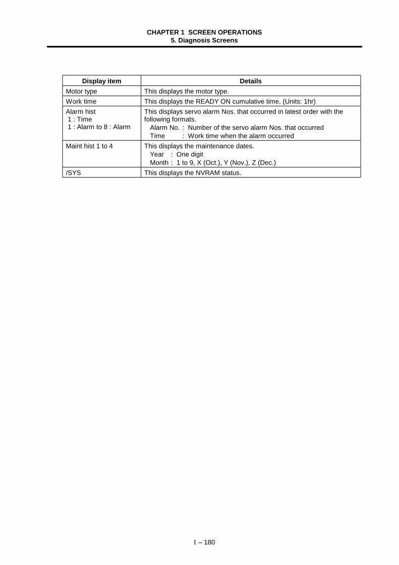
CHAPTER 1 SCREEN OPERATIONS5. Diagnosis Screens
I – 180
Display item DetailsMotor type This displays the motor type.Work time This displays the READY ON cumulative time. (Units: 1hr)Alarm hist 1 : Time 1 : Alarm to 8 : Alarm
This displays servo alarm Nos. that occurred in latest order with thefollowing formats.
Alarm No. : Number of the servo alarm Nos. that occurredTime : Work time when the alarm occurred
Maint hist 1 to 4 This displays the maintenance dates.Year : One digitMonth : 1 to 9, X (Oct.), Y (Nov.), Z (Dec.)
/SYS This displays the NVRAM status.
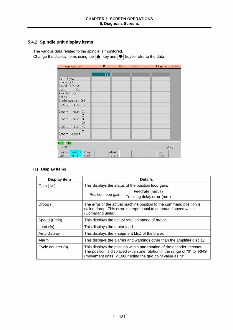
CHAPTER 1 SCREEN OPERATIONS5. Diagnosis Screens
I – 181
5.4.2 Spindle unit display items
The various data related to the spindle is monitored.Change the display items using the key and key to refer to the data.
(1) Display items
Display item DetailsGain (1/s) This displays the status of the position loop gain.
Position loop gain : Feedrate (mm/s)
Tracking delay error (mm)
Droop (i) The error of the actual machine position to the command position iscalled droop. This error is proportional to command speed value.(Command units)
Speed (r/min) This displays the actual rotation speed of motor.
Load (%) This displays the motor load.
Amp display This displays the 7-segment LED of the driver.
Alarm This displays the alarms and warnings other than the amplifier display.
Cycle counter (p) This displays the position within one rotation of the encoder detector.The position is displayed within one rotation in the range of "0" to "RNG(movement units) × 1000" using the grid point value as "0".
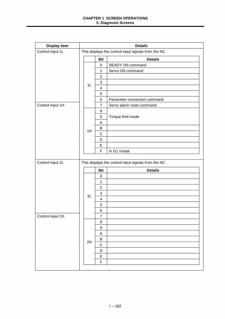
CHAPTER 1 SCREEN OPERATIONS5. Diagnosis Screens
I – 182
Display item DetailsThis displays the control input signals from the NC.
Bit Details0 READY ON command1 Servo ON command2345
Control input 1L
6 Parameter conversion command
1L
7 Servo alarm reset command89 Torque limit modeABCDE
1H
F In G1 modal
Control input 1H
This displays the control input signals from the NC.
Bit Details012345
Control input 2L
6
2L
789ABCDE
2H
F
Control input 2H
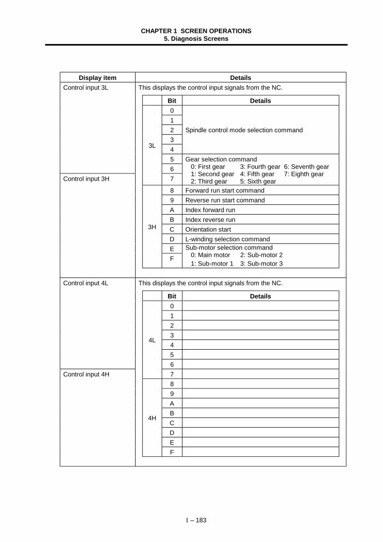
CHAPTER 1 SCREEN OPERATIONS5. Diagnosis Screens
I – 183
Display item DetailsThis displays the control input signals from the NC.
Bit Details012 Spindle control mode selection command345
Control input 3L
6
3L
7
Gear selection command0: First gear 3: Fourth gear 6: Seventh gear1: Second gear 4: Fifth gear 7: Eighth gear2: Third gear 5: Sixth gear
8 Forward run start command9 Reverse run start commandA Index forward runB Index reverse runC Orientation startD L-winding selection commandE
3H
F
Sub-motor selection command0: Main motor 2: Sub-motor 21: Sub-motor 1 3: Sub-motor 3
Control input 3H
This displays the control input signals from the NC.
Bit Details012345
Control input 4L
6
4L
789ABCDE
4H
F
Control input 4H
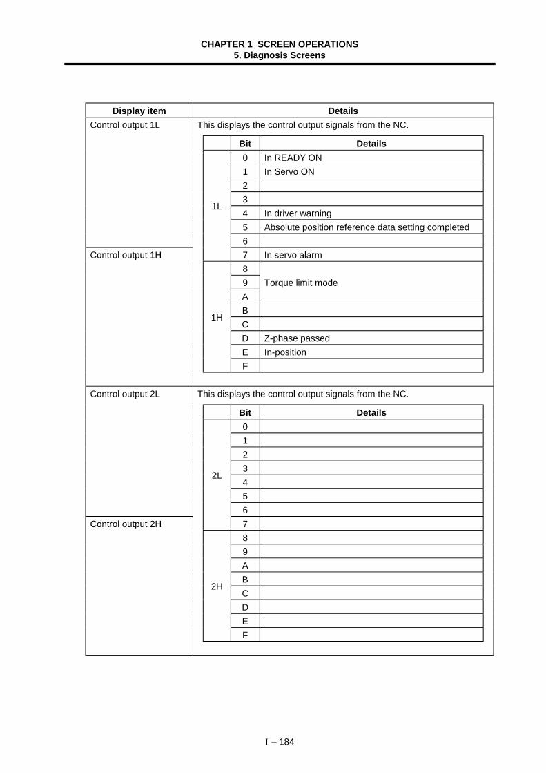
CHAPTER 1 SCREEN OPERATIONS5. Diagnosis Screens
I – 184
Display item DetailsThis displays the control output signals from the NC.
Bit Details0 In READY ON1 In Servo ON234 In driver warning5 Absolute position reference data setting completed
Control output 1L
6
1L
7 In servo alarm89 Torque limit modeABCD Z-phase passedE In-position
1H
F
Control output 1H
This displays the control output signals from the NC.
Bit Details012345
Control output 2L
6
2L
789ABCDE
2H
F
Control output 2H
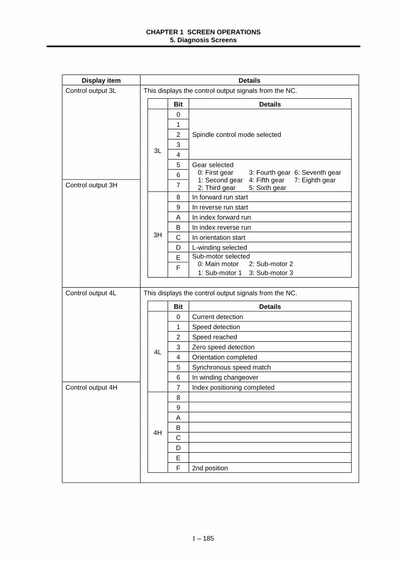
CHAPTER 1 SCREEN OPERATIONS5. Diagnosis Screens
I – 185
Display item DetailsThis displays the control output signals from the NC.
Bit Details012 Spindle control mode selected345
Control output 3L
6
3L
7
Gear selected0: First gear 3: Fourth gear 6: Seventh gear1: Second gear 4: Fifth gear 7: Eighth gear2: Third gear 5: Sixth gear
8 In forward run start9 In reverse run startA In index forward runB In index reverse runC In orientation startD L-winding selectedE
3H
F
Sub-motor selected0: Main motor 2: Sub-motor 21: Sub-motor 1 3: Sub-motor 3
Control output 3H
This displays the control output signals from the NC.
Bit Details0 Current detection1 Speed detection2 Speed reached3 Zero speed detection4 Orientation completed5 Synchronous speed match
Control output 4L
6 In winding changeover
4L
7 Index positioning completed89ABCDE
4H
F 2nd position
Control output 4H
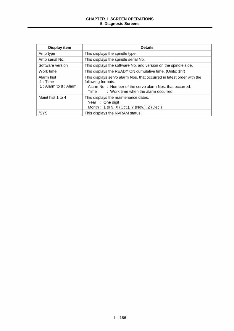
CHAPTER 1 SCREEN OPERATIONS5. Diagnosis Screens
I – 186
Display item DetailsAmp type This displays the spindle type.Amp serial No. This displays the spindle serial No.Software version This displays the software No. and version on the spindle side.Work time This displays the READY ON cumulative time. (Units: 1hr)Alarm hist 1 : Time 1 : Alarm to 8 : Alarm
This displays servo alarm Nos. that occurred in latest order with thefollowing formats.
Alarm No. : Number of the servo alarm Nos. that occurred.Time : Work time when the alarm occurred.
Maint hist 1 to 4 This displays the maintenance dates.Year : One digitMonth : 1 to 9, X (Oct.), Y (Nov.), Z (Dec.)
/SYS This displays the NVRAM status.
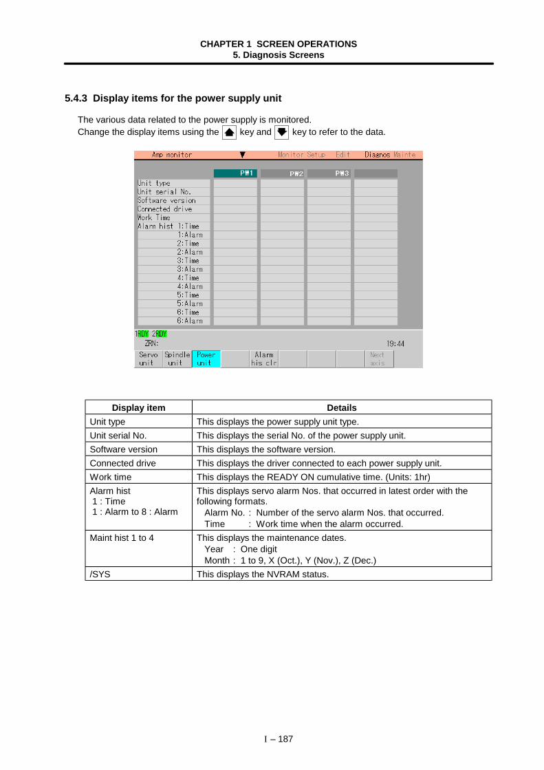
CHAPTER 1 SCREEN OPERATIONS5. Diagnosis Screens
I – 187
5.4.3 Display items for the power supply unit
The various data related to the power supply is monitored.Change the display items using the key and key to refer to the data.
Display item DetailsUnit type This displays the power supply unit type.Unit serial No. This displays the serial No. of the power supply unit.Software version This displays the software version.Connected drive This displays the driver connected to each power supply unit.Work time This displays the READY ON cumulative time. (Units: 1hr)Alarm hist 1 : Time 1 : Alarm to 8 : Alarm
This displays servo alarm Nos. that occurred in latest order with thefollowing formats.
Alarm No. : Number of the servo alarm Nos. that occurred.Time : Work time when the alarm occurred.
Maint hist 1 to 4 This displays the maintenance dates.Year : One digitMonth : 1 to 9, X (Oct.), Y (Nov.), Z (Dec.)
/SYS This displays the NVRAM status.
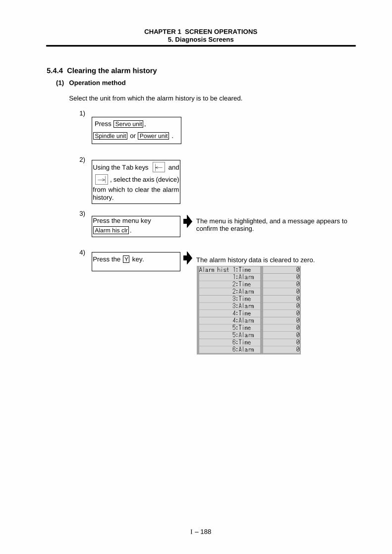
CHAPTER 1 SCREEN OPERATIONS5. Diagnosis Screens
I – 188
5.4.4 Clearing the alarm history(1) Operation method
Select the unit from which the alarm history is to be cleared.
1)
2)
3)The menu is highlighted, and a message appears toconfirm the erasing.
4)The alarm history data is cleared to zero.
Press the menu keyAlarm his clr .
Press the Y key.
Press Servo unit ,
Spindle unit or Power unit .
Using the Tab keys and
, select the axis (device)from which to clear the alarmhistory.
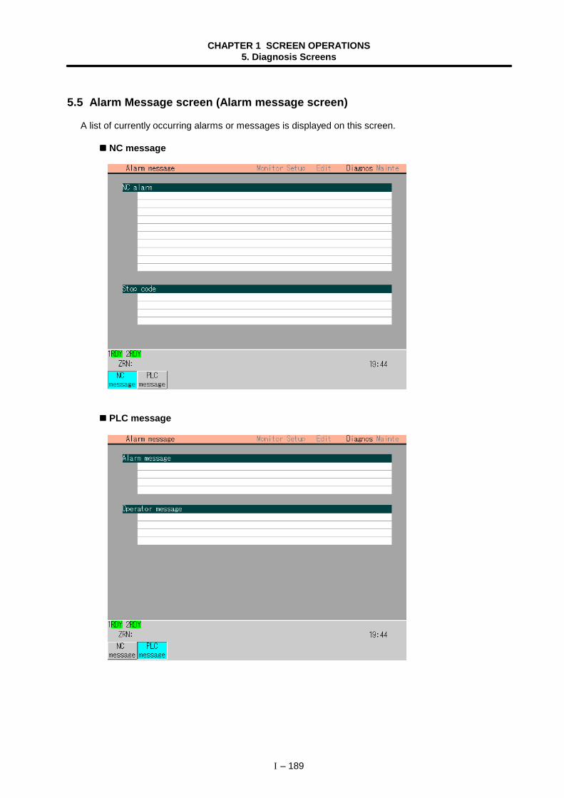
CHAPTER 1 SCREEN OPERATIONS5. Diagnosis Screens
I – 189
5.5 Alarm Message screen (Alarm message screen)
A list of currently occurring alarms or messages is displayed on this screen.
NC message
PLC message
CHAPTER 1 SCREEN OPERATIONS5. Diagnosis Screens
I – 190
(1) Display items
Display item DetailsNC alarm The code and number or message related to an NC alarm (operation
alarm, servo alarm, absolute position detection system alarm, spindlealarm, MCP alarm, system alarm and program error) are displayed.After confirming those items, on this screen, confirm the details in"Appendix 3. Alarm messages".
Stop code The NC automatic operation disable state or stop state during automaticoperation is indicated with a code and error No.After confirming those items, on this screen, confirm the details in"Appendix 3. Alarm messages".
Alarm message Using the user PLC, this displays messages such as details of machineabnormalities.
Operator message Using the user PLC, this displays operator information messages.
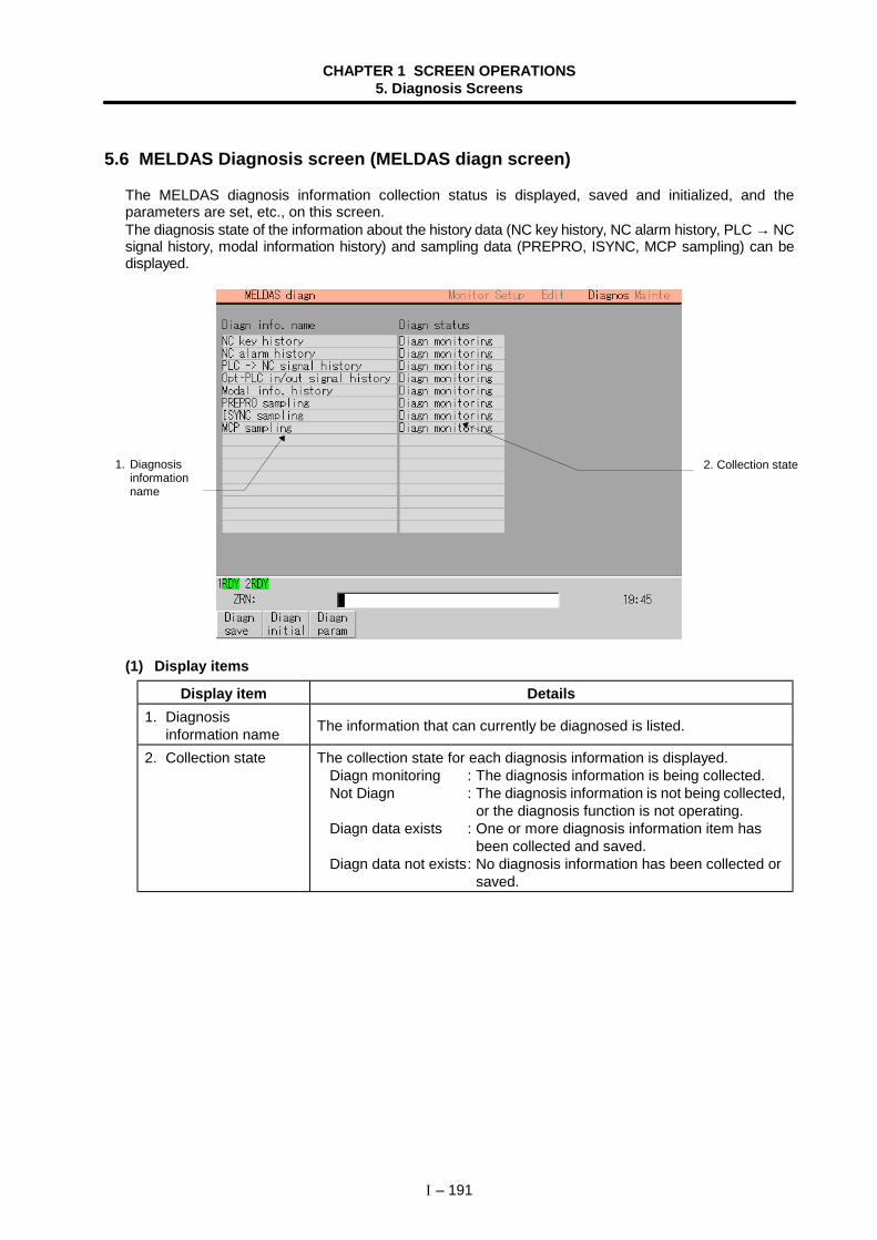
CHAPTER 1 SCREEN OPERATIONS5. Diagnosis Screens
I – 191
5.6 MELDAS Diagnosis screen (MELDAS diagn screen)
The MELDAS diagnosis information collection status is displayed, saved and initialized, and theparameters are set, etc., on this screen.The diagnosis state of the information about the history data (NC key history, NC alarm history, PLC → NCsignal history, modal information history) and sampling data (PREPRO, ISYNC, MCP sampling) can bedisplayed.
(1) Display items
Display item Details1. Diagnosis
information name The information that can currently be diagnosed is listed.
2. Collection state The collection state for each diagnosis information is displayed.Diagn monitoring : The diagnosis information is being collected.Not Diagn : The diagnosis information is not being collected,
or the diagnosis function is not operating.Diagn data exists : One or more diagnosis information item has
been collected and saved.Diagn data not exists: No diagnosis information has been collected or
saved.
2. Collection state1. Diagnosisinformationname
CHAPTER 1 SCREEN OPERATIONS5. Diagnosis Screens
I – 192
(2) Menus
Menu Details Type Reference
Diagnsave
The MELDAS diagnosis information is saved in afile (TRACK.MNT) on the hard disk. B
5.6.1 Saving theMELDAS diagnosisinformation
Diagninitial The MELDAS diagnosis information is initialized. B
5.6.2 Initializing theMELDAS diagnosisinformation
Diagnparam
The screen for setting the MELDAS-NETdiagnosis information parameters opens. C
5.6.3 MELDASDiagnosisParameter screen
5.6.1 Saving the MELDAS diagnosis information
1)A message confirming the saving appears.
2)The MELDAS diagnosis information is saved in"D:\SUPPORT\TRACK.MNT" on the hard disk.A dialog appears on the screen during the execution.When the information has been saved, the diagnosisinformation is initialized.
5.6.2 Initializing the MELDAS diagnosis information
1)A message confirming the initialization appears.
2)The MELDAS diagnosis information is initialized.
Caution
! If another screen is opened before saving the data on the MELDAS Diagnosis screen, the setdiagnosis information parameters will all be invalidated.
Press the menu Diagn save .
Press the menu Diagn initial .
Press Y or INPUT .
Press Y or INPUT .
To cancel the initialization, pressany key other than Y or . INPUT .
To cancel the saving, press any keyother than Y or . INPUT .
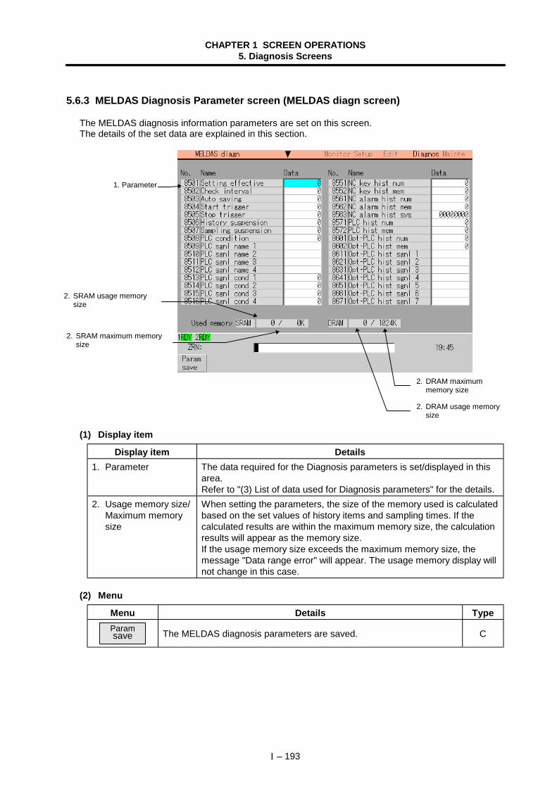
CHAPTER 1 SCREEN OPERATIONS5. Diagnosis Screens
I – 193
5.6.3 MELDAS Diagnosis Parameter screen (MELDAS diagn screen)
The MELDAS diagnosis information parameters are set on this screen.The details of the set data are explained in this section.
(1) Display item
Display item Details1. Parameter The data required for the Diagnosis parameters is set/displayed in this
area.Refer to "(3) List of data used for Diagnosis parameters" for the details.
2. Usage memory size/Maximum memorysize
When setting the parameters, the size of the memory used is calculatedbased on the set values of history items and sampling times. If thecalculated results are within the maximum memory size, the calculationresults will appear as the memory size.If the usage memory size exceeds the maximum memory size, themessage "Data range error" will appear. The usage memory display willnot change in this case.
(2) Menu
Menu Details TypeParamsave The MELDAS diagnosis parameters are saved. C
1. Parameter
2. SRAM usage memorysize
2. SRAM maximum memorysize
2. DRAM usage memorysize
2. DRAM maximummemory size
CHAPTER 1 SCREEN OPERATIONS5. Diagnosis Screens
I – 194
(3) List of data used for Diagnosis parameters
No. Setting item Details Setting range8501 Setting effective Select whether to validate the parameters set on the
MELDAS Diagnosis Parameter screen.0: Invalid (use default
parameters)1: Valid
8502 Check interval Set the interval to monitor whether the diagnosisinformation has been created on the NC side.When 0 is designated, the state will be monitored atthe default value (5-second interval).
0 to 9999 (s)
8503 Auto saving When automatic save is validated, if creation of thediagnosis conditions is detected on the HMI screen,the diagnosis information will be automatically saved inthe personal computer's hard disk.
0: Do notautomatically save
1: Automatically save
8504 Start trigger Select the conditions for starting collection of thediagnosis information.
0: Power ON1: Command from
program2: PLC signal
8505 Stop trigger Select the conditions for stopping collection of thediagnosis information.
0: Alarm1: Command from
program2: PLC signal
8506 History suspension Number of sampled data 0: 1/4 items1: 2/4 items2: 3/4 items3: 4/4 items
8507 Samplingsuspension
Sampling time 0: 1/4 (s)1: 2/4 (s)2: 3/4 (s)3: 4/4 (s)
8508 PLC condition [Valid only when Stop trigger is PLC signal]Set the conditions for establishing the PLC stop trigger(PLC signal 1 to PLC signal 4).
0: OR(One of the signalconditions is valid.)
1: AND(All signalconditions arevalid.)
CHAPTER 1 SCREEN OPERATIONS5. Diagnosis Screens
I – 195
No. Setting item Details Setting range8509 PLC sgnl name 18510 PLC sgnl name 28511 PLC sgnl name 38512 PLC sgnl name 4
[Valid only when Stop trigger is PLC signal]PLC signal device name
Bit device usable byNC
8513 PLC sgnl cond 18514 PLC sgnl cond 28515 PLC sgnl cond 38516 PLC sgnl cond 4
[Valid only when stop trigger is PLC signal]PLC signal establishment conditions
0: OFF → ON1: ON → OFF
8551 NC key hist num Set the number of history data items to sample. 0 to 9999 items8552 NC key hist mem Designate the range for saving the NC side history
data.(When DRAM is selected, the history data will not beheld after the power is turned OFF.)
0: DRAM1: SRAM
8561 NC alarm hist num Set the number of history data items to sample. 0 to 9999 items8562 NC alarm hist mem Designate the range for saving the NC side history
data.(When DRAM is selected, the history data will not beheld after the power is turned OFF.)
0: DRAM1: SRAM
8563 NC alarm hist sys Designate the system for sampling the history data. bit0: System 1bit1: System 2 :bit7: System 8
8571 PLC hist num Set the number of history data items to sample. 0 to 9999 items8572 PLC hist mem Designate the range for saving the NC side history
data.(When DRAM is selected, the history data will not beheld after the power is turned OFF.)
0: DRAM1: SRAM
8601 Opt-PLC hist num Set the number of history data items to sample. 0 to 9999 items8602 Opt-PLC hist mem Designate the range for saving the NC side history
data.(When DRAM is selected, the history data will not beheld after the power is turned OFF.)
0: DRAM1: SRAM
(Note 1) "8508 PLC condition 1" to "8516 PLC sgnl cond 4" are valid only when the PLC signal isselected for "8505 Stop trigger".
CHAPTER 1 SCREEN OPERATIONS5. Diagnosis Screens
I – 196
No. Setting item Details Setting range8611 Opt-PLC hist sigl 18621 Opt-PLC hist sigl 28631 Opt-PLC hist sigl 38641 Opt-PLC hist sigl 48651 Opt-PLC hist sigl 58661 Opt-PLC hist sigl 68671 Opt-PLC hist sigl 78681 Opt-PLC hist sigl 8
PLC signal device name Bit device usable byNC
8701 (Not used) (For future expansion)8702 (Not used) (For future expansion)8711 (Not used) (For future expansion)8712 (Not used) (For future expansion)8721 Modal hist num Set the number of history data items to sample. 0 to 9999 items8722 Modal hist mem Designate the range for saving the NC side history
data.(When DRAM is selected, the history data will not beheld after the power is turned OFF.)
0: DRAM1: SRAM
8723 Modal hist sys Designate the system for sampling the history data. bit0: System 1bit1: System 2 :bit7: System 8
8731 PREPRO sampnum
Set the number of sampling data items to sample. 0 to 9999 items
8732 PREPRO sampmem
Designate the range for saving the NC side samplingdata.(When DRAM is selected, the history data will not beheld after the power is turned OFF.)
0: DRAM1: SRAM
CHAPTER 1 SCREEN OPERATIONS5. Diagnosis Screens
I – 197
No. Setting item Details Setting range8733 PREPRO samp
axisSet the axis for sampling the data. bit0 : $1-1 axis
bit1 : $1-2 axis:
bit5 : $2-1 axis:
bit10 : $3-1 axis:
bit14 : $4-1 axis:
bit18 : $5-1 axis:
8741 ISYNC samp time Set the sampling time. 0 to 9999 (s)8742 ISYNC samp cycle Set the multiplier "n" value for the sampling cycle
calculation expression.(Task cycle) × 2n
Calculate the task cycle at 7.1ms.
0 to 8
8743 ISYNC samp mem Designate the range for saving the NC side samplingdata.(When DRAM is selected, the history data will not beheld after the power is turned OFF.)
0: DRAM1: SRAM
8744 ISYNC samp axis Set the axis for sampling the data. bit0 : $1-1 axisbit1 : $1-2 axis
:bit5 : $2-1 axis
:bit10 : $3-1 axis
:bit14 : $4-1 axis
:bit18 : $5-1 axis
:8751 MCP samp time Set the sampling time. 0 to 9999 (s)
CHAPTER 1 SCREEN OPERATIONS5. Diagnosis Screens
I – 198
No. Setting item Details Setting range8752 MCP samp cycle Set the multiplier "n" value for the sampling cycle
calculation expression.(Task cycle) × 2n
Calculate the task cycle at 3.5ms.
0 to 8
8753 MCP samp mem Designate the range for saving the NC side samplingdata.(When DRAM is selected, the history data will not beheld after the power is turned OFF.)
0: DRAM1: SRAM
8754 MCP samp spindle Designate the spindle for sampling the data.(Set the logical sum when the corresponding system'sbit is ON (1).)
bit0 : Spindle 1bit1 : Spindle 2
:bit5 : Spindle 6
8755 MCP samp axis Set the axis for sampling the data.(Set the logical sum when the corresponding system'sbit is ON (1).)
bit0 : $1-1 axisbit1 : $1-2 axis
:bit5 : $2-1 axis
:bit10 : $3-1 axis
:bit14 : $4-1 axis
:bit18 : $5-1 axis
:
(4) Saving the MELDAS diagnosis parameters1)
A message confirming the saving appears.
2)The MELDAS diagnosis parameters are saved in theNC memory, and then the diagnosis information isinitialized.
Caution
! If another screen is opened before saving the data on the MELDAS Diagnosis screen, the setdiagnosis information parameters will all be invalidated.
Press the menu Param save .
Press Y or INPUT .
To cancel the saving, press any keyother than Y or . INPUT .
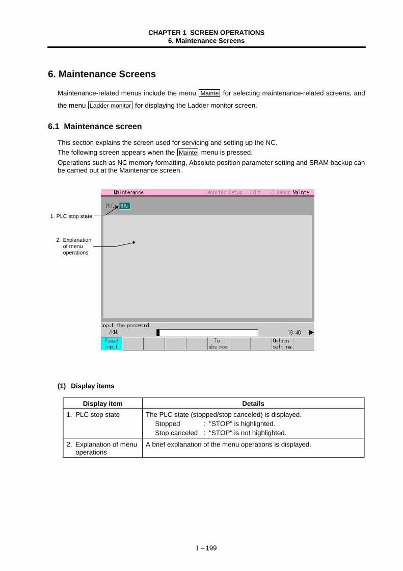
CHAPTER 1 SCREEN OPERATIONS6. Maintenance Screens
I – 199
6. Maintenance Screens
Maintenance-related menus include the menu Mainte for selecting maintenance-related screens, and
the menu Ladder monitor for displaying the Ladder monitor screen.
6.1 Maintenance screen
This section explains the screen used for servicing and setting up the NC.The following screen appears when the Mainte menu is pressed.Operations such as NC memory formatting, Absolute position parameter setting and SRAM backup canbe carried out at the Maintenance screen.
(1) Display items
Display item Details1. PLC stop state The PLC state (stopped/stop canceled) is displayed.
Stopped : "STOP" is highlighted. Stop canceled : "STOP" is not highlighted.
2. Explanation of menuoperations
A brief explanation of the menu operations is displayed.
2. Explanationof menuoperations
1. PLC stop state
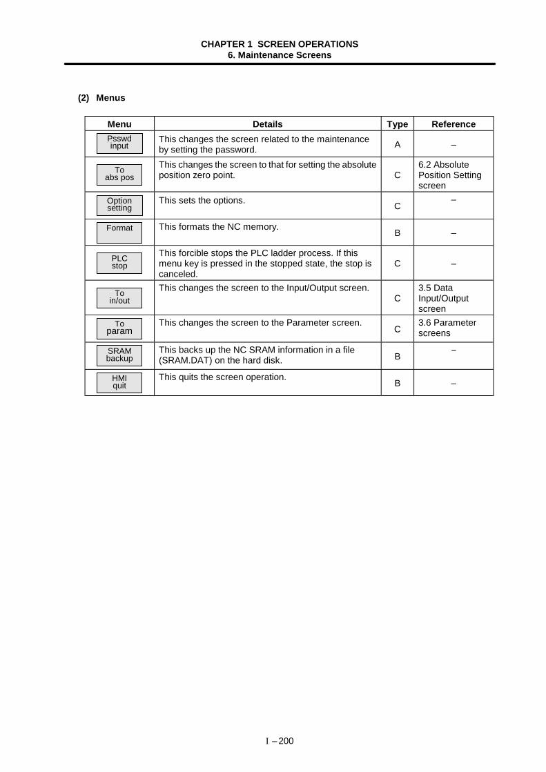
CHAPTER 1 SCREEN OPERATIONS6. Maintenance Screens
I – 200
(2) Menus
Menu Details Type ReferencePsswdinput
This changes the screen related to the maintenanceby setting the password. A –
Toabs pos
This changes the screen to that for setting the absoluteposition zero point. C
6.2 AbsolutePosition Settingscreen
Optionsetting
This sets the options. C–
Format This formats the NC memory. B –
PLCstop
This forcible stops the PLC ladder process. If thismenu key is pressed in the stopped state, the stop iscanceled.
C –
Toin/out
This changes the screen to the Input/Output screen.C
3.5 DataInput/Outputscreen
Toparam
This changes the screen to the Parameter screen.C
3.6 Parameterscreens
SRAMbackup
This backs up the NC SRAM information in a file(SRAM.DAT) on the hard disk. B −
HMIquit
This quits the screen operation. B –
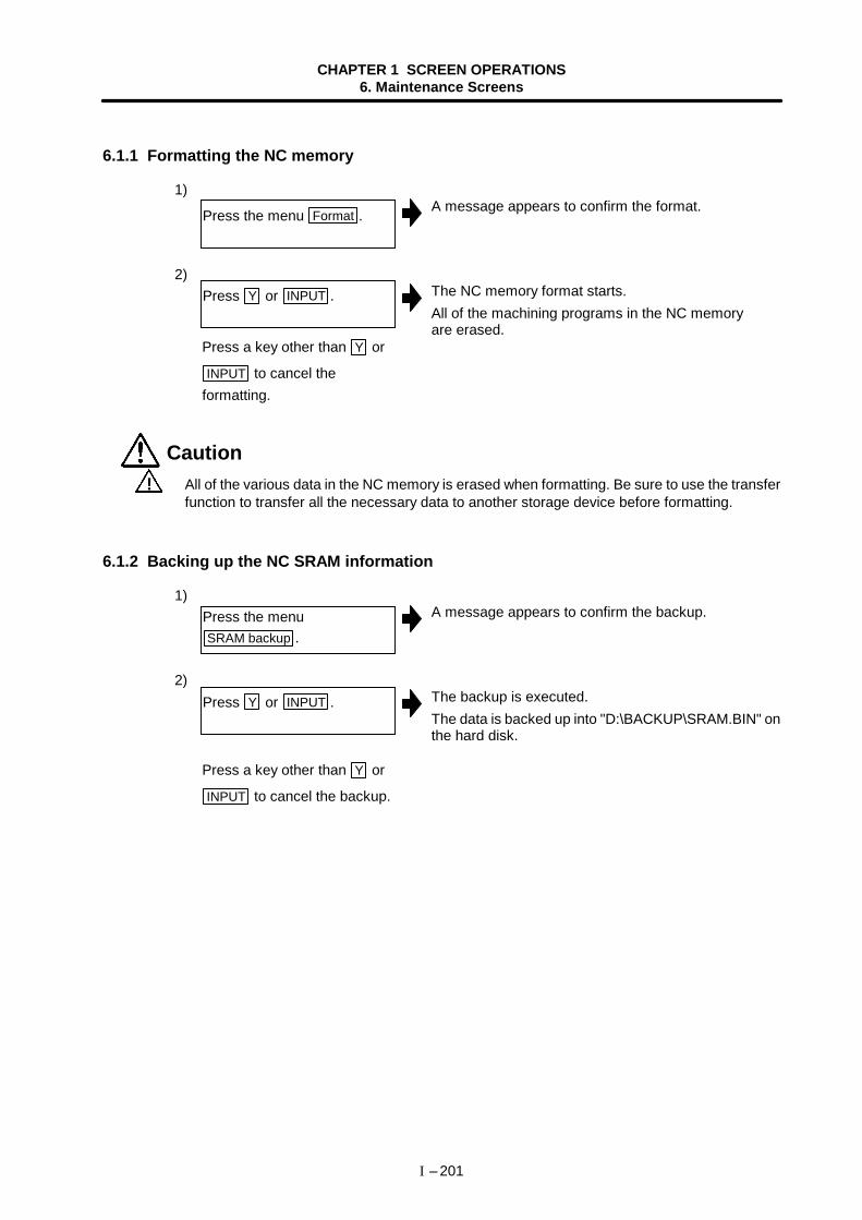
CHAPTER 1 SCREEN OPERATIONS6. Maintenance Screens
I – 201
6.1.1 Formatting the NC memory
1)A message appears to confirm the format.
2)The NC memory format starts.All of the machining programs in the NC memoryare erased.
Caution ! All of the various data in the NC memory is erased when formatting. Be sure to use the transfer
function to transfer all the necessary data to another storage device before formatting.
6.1.2 Backing up the NC SRAM information
1)A message appears to confirm the backup.
2)The backup is executed.The data is backed up into "D:\BACKUP\SRAM.BIN" onthe hard disk.
Press the menu Format .
Press Y or INPUT .
Press the menuSRAM backup .
Press Y or INPUT .
Press a key other than Y or
INPUT to cancel theformatting.
Press a key other than Y or
INPUT to cancel the backup.
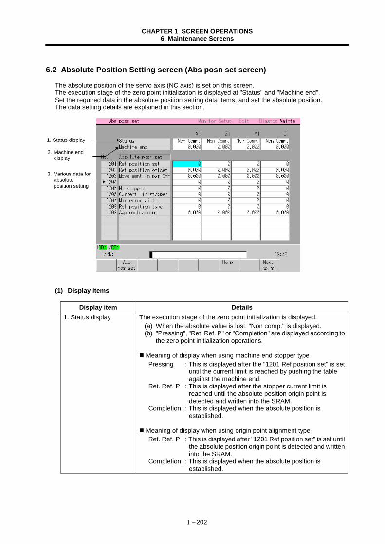
CHAPTER 1 SCREEN OPERATIONS6. Maintenance Screens
I – 202
6.2 Absolute Position Setting screen (Abs posn set screen)
The absolute position of the servo axis (NC axis) is set on this screen.The execution stage of the zero point initialization is displayed at "Status" and "Machine end".Set the required data in the absolute position setting data items, and set the absolute position.The data setting details are explained in this section.
(1) Display items
Display item Details1. Status display The execution stage of the zero point initialization is displayed.
(a) When the absolute value is lost, "Non comp." is displayed. (b) "Pressing", "Ret. Ref. P" or "Completion" are displayed according to
the zero point initialization operations.
Meaning of display when using machine end stopper typePressing : This is displayed after the "1201 Ref position set" is set
until the current limit is reached by pushing the tableagainst the machine end.
Ret. Ref. P : This is displayed after the stopper current limit isreached until the absolute position origin point isdetected and written into the SRAM.
Completion : This is displayed when the absolute position isestablished.
Meaning of display when using origin point alignment typeRet. Ref. P : This is displayed after "1201 Ref position set" is set until
the absolute position origin point is detected and writteninto the SRAM.
Completion : This is displayed when the absolute position isestablished.
3. Various data forabsoluteposition setting
1. Status display
2. Machine enddisplay
CHAPTER 1 SCREEN OPERATIONS6. Maintenance Screens
I – 203
Display item Details2. Machine end display The distance from the absolute position origin point to the grid point is
displayed. Display range : –99999.999 to 99999.999 (mm) (radius value display)
Meaning of display when using machine end stopper typeThe distance from the machine end to the previous grid point isdisplayed.
Meaning of display when using marked point alignment typeThe distance from the marked point to the previous grid point isdisplayed.When a grid mask is applied, the distance to the next grid point isdisplayed. This data is set to "0" when the power is turned ON.
3. Various data forabsolute positionsetting
This column is used to set and display the data required for absoluteposition setting.Refer to "(3) List of data related to absolute position setting" for details onsetting the absolute position.
(2) Menus
Menu Details Type
Abspos set
This changes between the zero point initialization execution/cancelstate. During zero point initialization, "Absolute posn set" on the screenis highlighted.This setting is canceled when the power is turned ON.
During execution:The absolute position detection data ("1201 Ref position set" and"1202 Ref position offset") can be changed on the screen.
Canceled state:The absolute position detection data ("1201 Ref position set" and"1202 Ref position offset") cannot be changed on the screen.
C
Help The screen explaining the methods of initializing the zero point andresetting the basic machine coordinate system will open. C
Nextaxis The displayed axis will change to the next axis. C
CHAPTER 1 SCREEN OPERATIONS6. Maintenance Screens
I – 204
(3) List of data related to absolute position setting
No. Setting item Details Setting range1201 Ref position set 0 : After the zero point is initialized and the absolute
position is established, "1202 Ref position offset"cannot be set.
1 : Zero point initialization can be executed.2 : The basic machine coordinate system can be
reset.
0 to 2Changes to "0"when the poweris turned OFFand theabsoluteposition isestablished.
1202 Ref position offset This sets the distance of the absolute position originpoint from the basic machine coordinate system zeropoint.Note that this cannot be set if "1201 Ref position set"is 0 after the absolute position is established or if anabsolute position detection alarm has occurred.(Note) Set with the following procedure:
• Select the detection method with the Basicaxis parameter "1011 abson", and turn thepower ON again.
• Set "Absolute posn set" "ON".(Press menu Abs pos set .)
• Set "1201 Ref position set" to "1". • Set "1202 Ref position offset". • Turn the power ON again, and carry out
reference point return.
± 99999.999 (mm)(Radius valuesetting)
1203 Move amnt in pwrOFF
This checks the difference of the machine positionswhen the power is turned OFF and turned ON again. Ifexcessive, this outputs the alarm "ABSOLUTEPOSITION ERROR".
When set to "0" 0.9 × PIT (ball screw pitch) × 1000 [µm]
0 to 99999.999 (mm)(Radius valuesetting)0 : Equivalent
to ball screwpitch
1204 Not used. 01205 No stopper This selects the zero point initialization method
(machine end stopper pushing method or method ofsetting reference point without using machine end).To carry out dogless reference point return, alwaysselect "0" (stopper method).
0 : Stoppermethod
1 : Referencepointmethod
1206 Current limstopper
This sets the current limit value for initialization.The setting value is a ratio of the limit current inrespect to the stall current.
Calculation expression
(Setting value) = × 100
0 to 500 (%)
1207 Max error width This sets the excessive error width for pushing duringabsolute position setting using the machine endstopper type.
0 to 32767(mm)
(Limit current)(Stall current [Peak])
CHAPTER 1 SCREEN OPERATIONS6. Maintenance Screens
I – 205
No. Setting item Details Setting range1208 Ref position type This selects whether the absolute position origin point
is a random point (machine end or marked point) or agrid point.When set as a grid point, operations to move to thegrid position are required.
Absolute positionorigin point
Machineend
Machineoriginposition
"1202 Ref position offset"
(When 1208 Ref position type" is set to "1")
"1202 Ref position offset"(When 1208 Ref position type" is set to "0")
Grid point
0 : Randompoint
1 : Grid point
1209 Approach amount Designate, as an absolute value, the distance (relativedistance from pressing point) to start the secondpressing during automatic dog-less reference pointreturn.When "0" is set, a value double grspc (grid interval)will be set.
0 to 99999.999(mm)(radius valuesetting)
CHAPTER 1 SCREEN OPERATIONS6. Maintenance Screens
I – 206
6.2.1 Selecting the axis
(1) Operation method
1)The section displaying the axis name and the details ofeach data will change to that for the next axis.
6.2.2 Displaying the Help screen
On this screen, the operation procedures for initializing the zero point and for resetting the basic machinecoordinate system are displayed.The Abs posn set screen will reappear if the C·B CANCEL key is pressed.
(1) Menus
Menu Details TypeMachine
gridThe operation procedures for the machine end stopper (grid point) type aredisplayed. B
Machineoptinal
The operation procedures for the machine end stopper (random point) typeare displayed. B
Ref.pntgrid
The operation procedures for the marked point definition (grid point) typeare displayed. B
Ref.pntoptinal
The operation procedures for the marked point definition (random point)type are displayed. B
Coordre-set
The operation procedures for resetting the basic machine coordinatesystem are displayed. B
Press the Next axis menu.
If the Next axis menu ispressed while the last axis isdisplayed, the display willchange to the first axis.
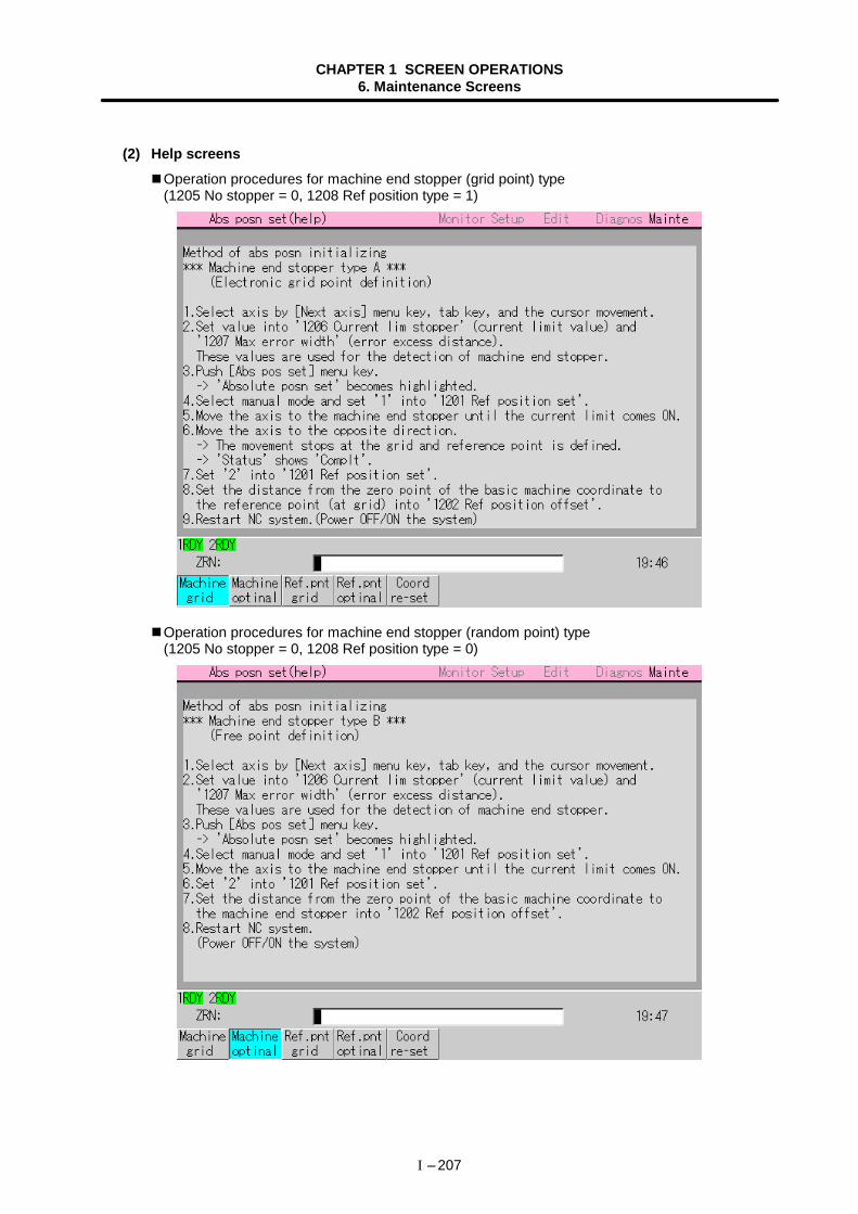
CHAPTER 1 SCREEN OPERATIONS6. Maintenance Screens
I – 207
(2) Help screensOperation procedures for machine end stopper (grid point) type(1205 No stopper = 0, 1208 Ref position type = 1)
Operation procedures for machine end stopper (random point) type(1205 No stopper = 0, 1208 Ref position type = 0)
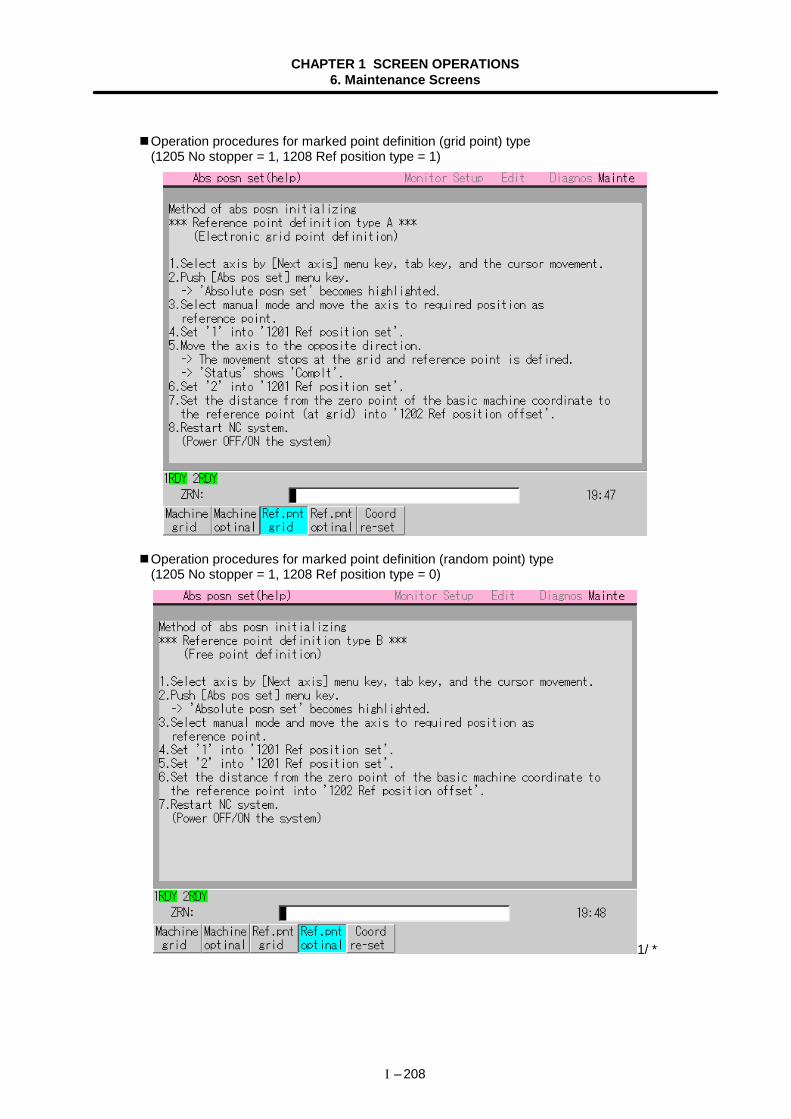
CHAPTER 1 SCREEN OPERATIONS6. Maintenance Screens
I – 208
Operation procedures for marked point definition (grid point) type(1205 No stopper = 1, 1208 Ref position type = 1)
Operation procedures for marked point definition (random point) type(1205 No stopper = 1, 1208 Ref position type = 0)
1/ *
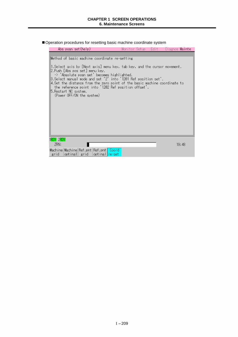
CHAPTER 1 SCREEN OPERATIONS6. Maintenance Screens
I – 209
Operation procedures for resetting basic machine coordinate system
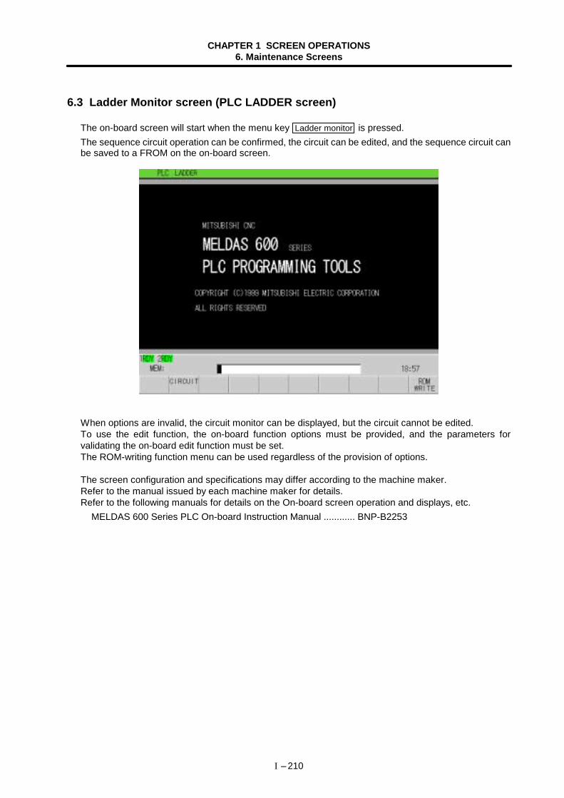
CHAPTER 1 SCREEN OPERATIONS6. Maintenance Screens
I – 210
6.3 Ladder Monitor screen (PLC LADDER screen)
The on-board screen will start when the menu key Ladder monitor is pressed.The sequence circuit operation can be confirmed, the circuit can be edited, and the sequence circuit canbe saved to a FROM on the on-board screen.
When options are invalid, the circuit monitor can be displayed, but the circuit cannot be edited.To use the edit function, the on-board function options must be provided, and the parameters forvalidating the on-board edit function must be set.The ROM-writing function menu can be used regardless of the provision of options.
The screen configuration and specifications may differ according to the machine maker.Refer to the manual issued by each machine maker for details.Refer to the following manuals for details on the On-board screen operation and displays, etc.
MELDAS 600 Series PLC On-board Instruction Manual ............ BNP-B2253

CHAPTER 2 MACHINE OPERATIONS
CHAPTER 2 MACHINE OPERATIONS
II – 1
This chapter explains the functions and operation method of the machine operation switches for NCoperation (automatic operation and manual operation) by using the illustration of the machine operationpanel below.The actual machine operation and motion vary with each machine. Refer to the operation manual issued bythe machine manufacturer. Use this chapter for reference.
M D I
MODE SELECT
ON
OFF
ON
OFF
ON
OFF
ON
OFF
ON
OFF
ON
OFF
ON
OFF
ON
OFF
ON
OFF
ON
OFF
ON
OFF
ON
OFF
ON
OFF
ON
OFF
ON
OFF
ON
OFF
ON
OFF
ON
OFF
ON
OFF
10050
1
25
%
RAPID TRAVERSEOVERRIDE
%
CUTTING FEEDOVERRIDE
160170180190200210220230240250260270280290300
150140130120110100
908070605040302010
0
SPINDLE OVERRIDE
%
100
50
60
7080 90
110
120 CYCLE START FEED HOLD
EMERGENCY STOP
REFERENCE POINT
X Z C
FEED AXIS SELECT
+X
-X
+Z
-Z
+C
-C
RESET
XZ
C
HANDLE FEEDAXIS SELECT
HANDLE/INCREMENTALMAGNIFICATION
1010000
11
1010
100100
10001000
15000
100500001000
100000
mm/min
MANUAL FEEDRATE
10072.052.037.027.020.014.010.07.25.23.72.72.01.41.0
0
140.0200.0270.0370.0520.0720.01000.01400.02000.02700.03700.05200.07200.010000.014000.0
HANDLE
00 +- 72
MELDAS
OPTIONALSTOPCZXDISPLAY
LOCKDRY RUNMANUALOVERRIDE
DETECTERROR
MANUALABSOLUTE
MIRRORIMAGE
CHAMFERINGHANDLEINTERRUPT
RAPID TRAVERSE
INCREMENTAL
REFERENCE POINTRETURN
HANDLE
JOG
PROGRAM RUN
CONTROLUNIT READY
IN AUTOOPERATION
NC ALARM M00 M01 M02/M30OVERRIDECANCEL
SINGLEBLOCK
MISCELLA-NEOUSFUNCTIONLOCK
OPTIONALBLOCK SKIP
MachineLock All Axes
CHAPTER 2 MACHINE OPERATIONS1. Operation State
II – 2
1. Operation State
1.1 Operation state transition diagram
The NC unit operation state changes momentarily according to the program contents or signals fromthe operation panel or machine. The controller roughly classifies the operation state into power OFF,not ready, and ready.NC operation is enabled only in the operating preparation ready state. The operating preparation readystate is furthermore classified into reset, automatic operation stop, automatic operation start, andautomatic operation pause, etc., as shown below.Manual mode operation is enabled in the operation complete state.
Screen operations
Monitor
Diagnosis
Machining programsearch
Compensation andvariable data setting
M02/M30
4
5
6
1
2
34
5
6
7
8
6
5
Power OFF stateNC power OFF
Operations not ready state Waiting for READY ON Failure in operating preparations(Emergency stop)
READY ON Problem is resolved Emergency stop
Resolve problemthat causedemergency stopOperations ready state
Reset operations
In automatic operations
Automatic operationis stopped
Feed hold Automaticoperationis started
Automatic operationin progress
Blockstop
Automaticoperationis started
Automatic operation isstopped
Start
Reset process
ResetFinishedprocess-ing
Auto
mat
ic o
pera
tion
stan
dby
stat
e
Reset operations
Screen operations(Machinery preparation)
During operation of the above, automatic start is not possible.
NC power ON
1.2 Power OFF
The power OFF state means that no power is supplied to the control circuit.(1) From any other state to power OFF (transition 1)
• When the POWER OFF switch of the setting display unit is pressed. • When POWER OFF signal is input from the machine.
• When the power supplied from the machine to NC unit is turned OFF. • When the fuse for the power unit in the NC unit has blown.
CHAPTER 2 MACHINE OPERATIONS1. Operation State
II – 3
1.3 Not ready
The operation preparation not ready state means that the system is not ready to run because of the NCunit itself or because of the machine, even though power is supplied to the NC unit control circuit. TheREADY lamp on the setting display unit is OFF.(1) From power OFF to not ready (transition 2)
• When the POWER ON switch of the setting display unit is pressed.• When POWER ON signal is input from the machine.
(2) From ready to not ready (transition 3)• When EMG (emergency stop) is displayed on the setting display unit screen.• When any of the following alarms is displayed on the setting display unit screen;
Servo alarm, feedback alarm, excessive error alarm, etc.
1.4 Ready
The operating preparation ready state means that power is supplied to the NC unit control circuit andthe system is ready to run. The READY lamp on the setting display unit is ON.The state is furthermore classified into the following four.
1.4.1 Reset
The reset state means that the NC unit is reset.(1) From not ready to reset (transition 4)
This state is also called initial state.Approximately four seconds after turning power ON
(2) From another ready state to reset (transition 5)• When the "RESET" key on the setting display unit is turned ON.• When external reset signal is input from the machine.• When M02 or M30 is executed (depending on the machine specifications).
1.4.2 Automatic operation start
The automatic operation start state means starting in automatic mode. The IN-AUTO OPERATIONlamp on the machine operation panel is ON.(1) From another automatic operation ready state to automatic operation start (transition 6)
• When the "CYCLE START" switch on the machine operation panel is pressed in automaticmode.
CAUTION Do not enter the movable range of the machine during automatic operation. Make sure not to
place hands, legs or face near the spindle during rotation.
CHAPTER 2 MACHINE OPERATIONS1. Operation State
II – 4
1.4.3 Automatic operation pause
The automatic operation pause state means that operation or motion temporarily pauses duringexecution of one block during the automatic operation start. The AUTO PAUSE lamp on the machineoperation panel is ON and the AUTO START lamp is OFF.(1) From automatic operation start to automatic pause (transition 7)
• When the "FEED HOLD" switch on the machine operation panel is turned ON.• When automatic mode input is out.
1.4.4 Automatic operation stop
The automatic operation stop state means that execution of one block is completed and stoppedduring automatic operation start. Both the AUTO START and AUTO PAUSE lamps on the machineoperation panel are OFF.(1) From automatic operation start to automatic operation stop (transition 8)
• When the "SINGLE BLOCK" switch on the machine operation panel is turned ON andexecution of the block is complete.
• When automatic mode input is changed to another automatic mode input.
CHAPTER 2 MACHINE OPERATIONS2. Indicator Lamps
II – 5
2. Indicator Lamps
2.1 NC unit ready
The NC UNIT READY lamp indicates that the NC unit is ready to run. The lamp goes off at emergencystop or when an alarm occurs in the drive or operation block.
2.2 Automatic operation busy
The AUTO BUSY lamp is ON from "CYCLE START" switch turning ON in the automatic operationmode (program run, or MDI) to the program end after M02 or M30 execution, reset, or emergencystop.
2.3 Automatic operation start busy
The AUTO START BUSY lamp indicates that the NC unit is executing control in the automaticoperation mode. It is ON from the automatic operation start state entered when the "CYCLE START"switch is pressed in the automatic operation mode (program run, or MDI) to the automatic operationstart end such as the automatic operation pause busy state entered when the "FEED HOLD" switch ispressed or block completion stop (block stop).
2.4 Automatic operation pause busy
The AUTO PAUSE lamp is ON from "FEED HOLD" switch turning ON to "CYCLE START" switchturning ON or when the mode selection switch is changed from the automatic mode to manual modeduring the automatic operation.
2.5 Return to reference point
Output is executed when the control axis arrives at the reference point during manual and automaticreference point return and reference point comparison.
2.6 NC alarm
The ALARM lamp goes on when an alarm occurs during NC operation.
2.7 M00
When M00 commanded in a program is executed during automatic operation, automatic operation isstopped after the block including M00 is completed. The M00 lamp lights up in this case. (Thisdepends on the PLC process.)
CHAPTER 2 MACHINE OPERATIONS2. Indicator Lamps
II – 6
2.8 M01
When M01 commanded in the program is executed during automatic operation, the system checkswhether the optional selection switch is ON or OFF. If OFF, the next block is executed, and if ON,automatic operation is stopped after the block is completed. The M01 lamp lights up in this case. (Thisdepends on the PLC process.)
2.9 M02/M30
When M02 or M30 is executed during automatic operation, the NC unit reaches the program end andthe M02 or M30 lamp is turned ON. (This depends on the PLC process.)
CHAPTER 2 MACHINE OPERATIONS3. Reset Switch and Emergency Stop Button
II – 7
3. Reset Switch and Emergency Stop Button
3.1 Reset switch
The NC unit is reset by turning ON the "RESET" switch on the machine operation panel or the"RESET" key on the setting display unit. When the "RESET" switch or key is turned ON while thecontroller is running, the unit is placed in one of the following states.1) If a movement command is being executed, move stops with deceleration and the remaining
distance in the executing block is cleared.2) If miscellaneous function such as M, S, or T is being executed, execution of the miscellaneous
function is interrupted.3) The active and buffer memory contents and display are cleared.4) If a program error occurs and remains, the program error state is cleared and the ALARM lamp
goes off.5) Input/output is stopped while the input/output unit is being used.6) If reset 2 is input, the modal state will be initialized.
3.2 Emergency stop button
The "EMERGENCY STOP" button is a red mushroom-shape pushbutton. The not ready state is set bypressing the "EMERGENCY STOP" button.During emergency stop, the READY lamp goes off and automatic operation and manual operation donot work. The NC unit is reset.If the "EMERGENCY STOP" button is pressed when a movement command is executed, the movingaxis stops and all other machine motions also stop.When the "EMERGENCY STOP" button is released, the READY lamp goes on in about one secondand operation enable state (ready state) is entered.When parameter is emergency stop hold type, if the "EMERGENCY STOP" button is released, theemergency stop state is held. To release the emergency stop state, turn ON the "RESET" switch.If the "EMERGENCY STOP LIMIT" switch of each axis works, the same state as if the "EMERGENCYSTOP" button were pressed may be entered depending on the machine specifications.
CAUTION If the axis overruns or makes an abnormal noise, press the emergency stop button
immediately, and stop the axis.
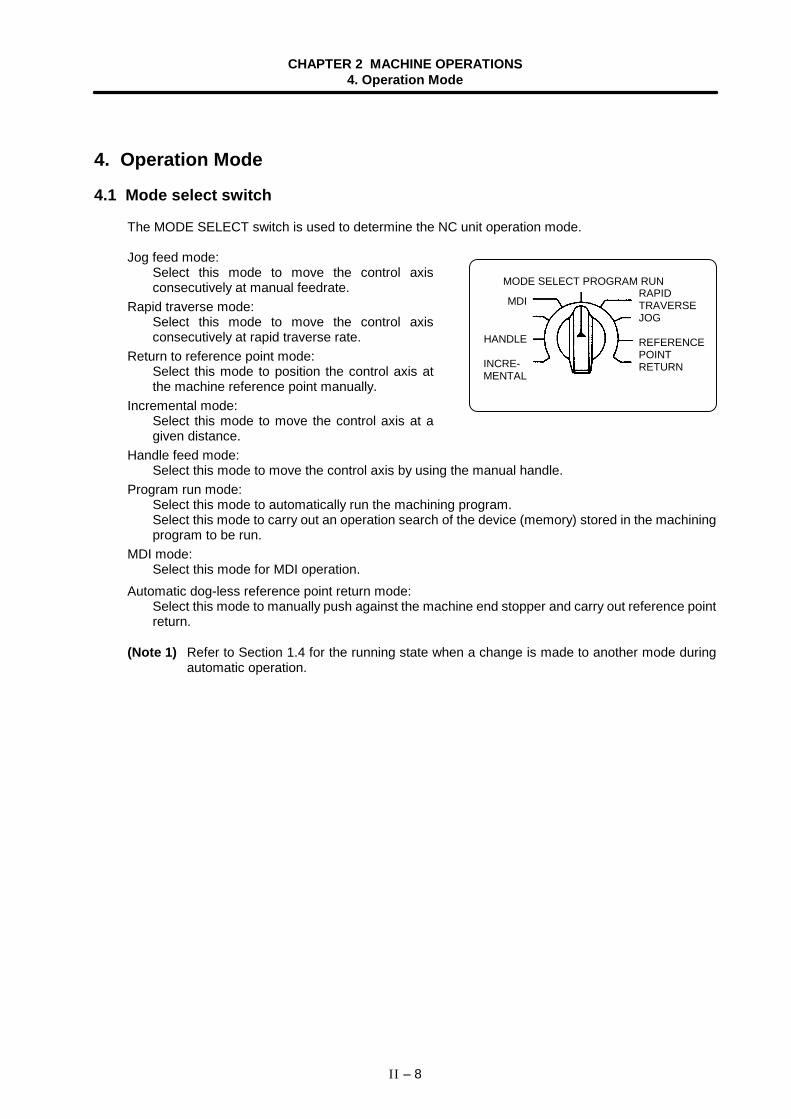
CHAPTER 2 MACHINE OPERATIONS4. Operation Mode
II – 8
4. Operation Mode
4.1 Mode select switch
The MODE SELECT switch is used to determine the NC unit operation mode.
Jog feed mode:Select this mode to move the control axisconsecutively at manual feedrate.
Rapid traverse mode:Select this mode to move the control axisconsecutively at rapid traverse rate.
Return to reference point mode:Select this mode to position the control axis atthe machine reference point manually.
Incremental mode:Select this mode to move the control axis at agiven distance.
Handle feed mode:Select this mode to move the control axis by using the manual handle.
Program run mode:Select this mode to automatically run the machining program.Select this mode to carry out an operation search of the device (memory) stored in the machiningprogram to be run.
MDI mode:Select this mode for MDI operation.
Automatic dog-less reference point return mode:Select this mode to manually push against the machine end stopper and carry out reference pointreturn.
(Note 1) Refer to Section 1.4 for the running state when a change is made to another mode duringautomatic operation.
MODE SELECT PROGRAM RUNRAPIDTRAVERSEJOG
REFERENCEPOINTRETURN
MDI
HANDLE
INCRE- MENTAL
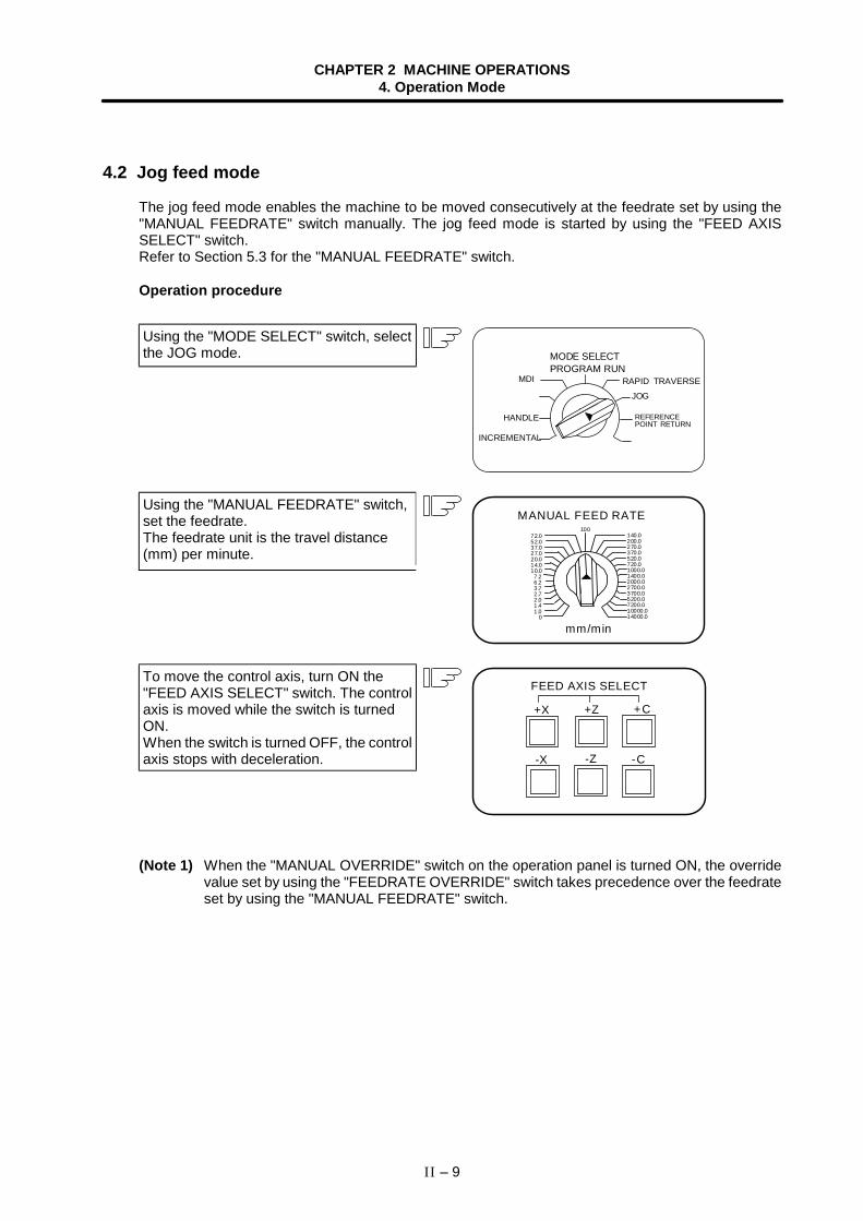
CHAPTER 2 MACHINE OPERATIONS4. Operation Mode
II – 9
4.2 Jog feed mode
The jog feed mode enables the machine to be moved consecutively at the feedrate set by using the"MANUAL FEEDRATE" switch manually. The jog feed mode is started by using the "FEED AXISSELECT" switch.Refer to Section 5.3 for the "MANUAL FEEDRATE" switch.
Operation procedure
Using the "MODE SELECT" switch, selectthe JOG mode. MODE SELECT
PROGRAM RUNRAPID TRAVERSE
JOG
INCREMENTAL
HANDLE
MDI
REFERENCEPOINT RETURN
Using the "MANUAL FEEDRATE" switch,set the feedrate.The feedrate unit is the travel distance(mm) per minute.
mm/min
MANUAL FEED RATE100
72.052.037.027.020.014.010.07.26.23.72.72.01.41.0
0
140.0200.0270.0370.0520.0720.01000.01400.02000.02700.03700.05200.07200.010000.014000.0
To move the control axis, turn ON the"FEED AXIS SELECT" switch. The controlaxis is moved while the switch is turnedON.When the switch is turned OFF, the controlaxis stops with deceleration.
FEED AXIS SELECT
+X
-X
+Z
-Z
+C
-C
(Note 1) When the "MANUAL OVERRIDE" switch on the operation panel is turned ON, the overridevalue set by using the "FEEDRATE OVERRIDE" switch takes precedence over the feedrateset by using the "MANUAL FEEDRATE" switch.
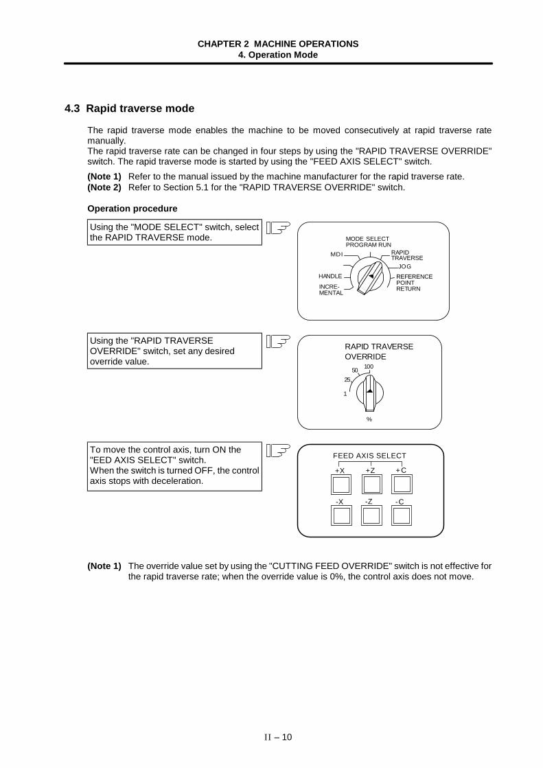
CHAPTER 2 MACHINE OPERATIONS4. Operation Mode
II – 10
4.3 Rapid traverse mode
The rapid traverse mode enables the machine to be moved consecutively at rapid traverse ratemanually.The rapid traverse rate can be changed in four steps by using the "RAPID TRAVERSE OVERRIDE"switch. The rapid traverse mode is started by using the "FEED AXIS SELECT" switch.(Note 1) Refer to the manual issued by the machine manufacturer for the rapid traverse rate.(Note 2) Refer to Section 5.1 for the "RAPID TRAVERSE OVERRIDE" switch.
Operation procedure
Using the "MODE SELECT" switch, selectthe RAPID TRAVERSE mode.
MDI
MODE SELECTPROGRAM RUN
HANDLE
INCRE-MENTAL
RAPIDTRAVERSE
JOGREFERENCEPOINTRETURN
Using the "RAPID TRAVERSEOVERRIDE" switch, set any desiredoverride value.
25
10050
1
%
RAPID TRAVERSEOVERRIDE
To move the control axis, turn ON the"EED AXIS SELECT" switch.When the switch is turned OFF, the controlaxis stops with deceleration.
FEED AXIS SELECT
+X
-X
+Z
-Z
+C
-C
(Note 1) The override value set by using the "CUTTING FEED OVERRIDE" switch is not effective forthe rapid traverse rate; when the override value is 0%, the control axis does not move.
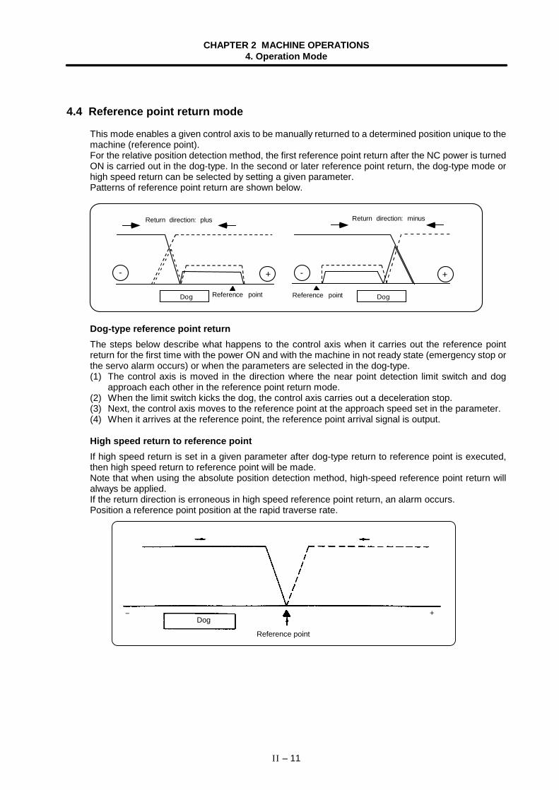
CHAPTER 2 MACHINE OPERATIONS4. Operation Mode
II – 11
4.4 Reference point return mode
This mode enables a given control axis to be manually returned to a determined position unique to themachine (reference point).For the relative position detection method, the first reference point return after the NC power is turnedON is carried out in the dog-type. In the second or later reference point return, the dog-type mode orhigh speed return can be selected by setting a given parameter.Patterns of reference point return are shown below.
+- +
Dog Reference point
Return direction: plus
-
Reference point
Return direction: minus
Dog
Dog-type reference point returnThe steps below describe what happens to the control axis when it carries out the reference pointreturn for the first time with the power ON and with the machine in not ready state (emergency stop orthe servo alarm occurs) or when the parameters are selected in the dog-type.(1) The control axis is moved in the direction where the near point detection limit switch and dog
approach each other in the reference point return mode.(2) When the limit switch kicks the dog, the control axis carries out a deceleration stop.(3) Next, the control axis moves to the reference point at the approach speed set in the parameter.(4) When it arrives at the reference point, the reference point arrival signal is output.
High speed return to reference pointIf high speed return is set in a given parameter after dog-type return to reference point is executed,then high speed return to reference point will be made.Note that when using the absolute position detection method, high-speed reference point return willalways be applied.If the return direction is erroneous in high speed reference point return, an alarm occurs.Position a reference point position at the rapid traverse rate.
+
Reference point
Dog −
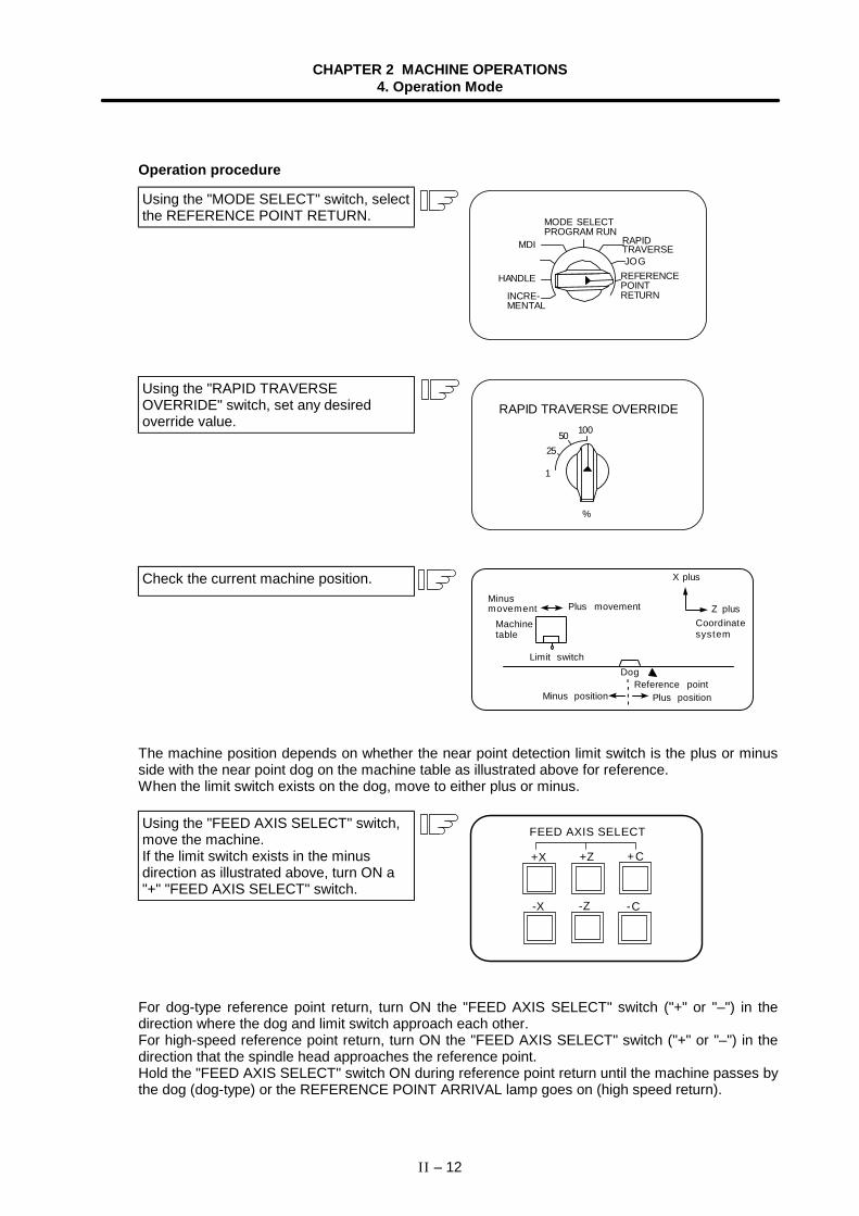
CHAPTER 2 MACHINE OPERATIONS4. Operation Mode
II – 12
Operation procedure
Using the "MODE SELECT" switch, selectthe REFERENCE POINT RETURN. MODE SELECT
PROGRAM RUNMDI
JOG
HANDLE
INCRE-MENTAL
RAPIDTRAVERSE
REFERENCEPOINTRETURN
Using the "RAPID TRAVERSEOVERRIDE" switch, set any desiredoverride value.
25
10050
1
%
RAPID TRAVERSE OVERRIDE
Check the current machine position.
The machine position depends on whether the near point detection limit switch is the plus or minusside with the near point dog on the machine table as illustrated above for reference.When the limit switch exists on the dog, move to either plus or minus.
Using the "FEED AXIS SELECT" switch,move the machine.If the limit switch exists in the minusdirection as illustrated above, turn ON a"+" "FEED AXIS SELECT" switch.
FEED AXIS SELECT
+X
-X
+Z
-Z
+C
-C
For dog-type reference point return, turn ON the "FEED AXIS SELECT" switch ("+" or "–") in thedirection where the dog and limit switch approach each other.For high-speed reference point return, turn ON the "FEED AXIS SELECT" switch ("+" or "–") in thedirection that the spindle head approaches the reference point.Hold the "FEED AXIS SELECT" switch ON during reference point return until the machine passes bythe dog (dog-type) or the REFERENCE POINT ARRIVAL lamp goes on (high speed return).
DogLimit switch
Minus position Plus position
Minusmovement
Reference point
Z plusCoordinatesystem
X plus
Plus movement
Machinetable
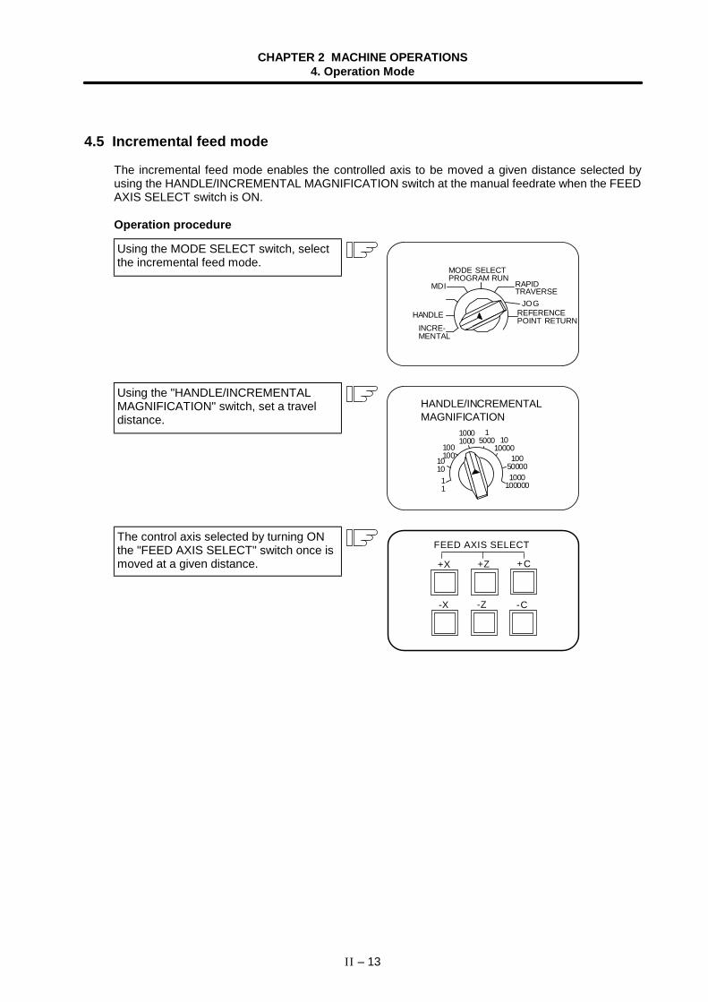
CHAPTER 2 MACHINE OPERATIONS4. Operation Mode
II – 13
4.5 Incremental feed mode
The incremental feed mode enables the controlled axis to be moved a given distance selected byusing the HANDLE/INCREMENTAL MAGNIFICATION switch at the manual feedrate when the FEEDAXIS SELECT switch is ON.
Operation procedure
Using the MODE SELECT switch, selectthe incremental feed mode.
MODE SELECTPROGRAM RUN
MDI
HANDLEINCRE-MENTAL
RAPIDTRAVERSE
JOGREFERENCEPOINT RETURN
Using the "HANDLE/INCREMENTALMAGNIFICATION" switch, set a traveldistance.
1010000
11
1010
100100
10001000
15000
100500001000
100000
HANDLE/INCREMENTALMAGNIFICATION
The control axis selected by turning ONthe "FEED AXIS SELECT" switch once ismoved at a given distance.
FEED AXIS SELECT
+X
-X
+Z
-Z
+C
-C
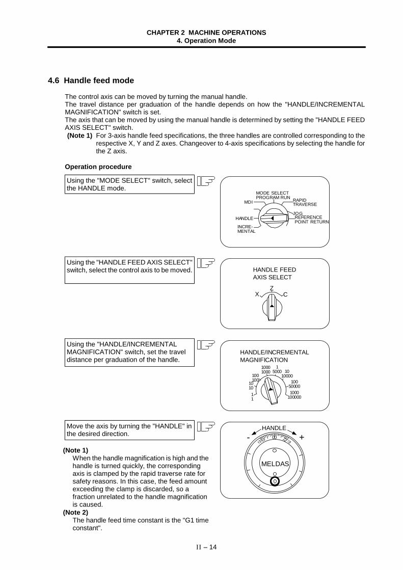
CHAPTER 2 MACHINE OPERATIONS4. Operation Mode
II – 14
4.6 Handle feed mode
The control axis can be moved by turning the manual handle.The travel distance per graduation of the handle depends on how the "HANDLE/INCREMENTALMAGNIFICATION" switch is set.The axis that can be moved by using the manual handle is determined by setting the "HANDLE FEEDAXIS SELECT" switch.(Note 1) For 3-axis handle feed specifications, the three handles are controlled corresponding to the
respective X, Y and Z axes. Changeover to 4-axis specifications by selecting the handle forthe Z axis.
Operation procedure
Using the "MODE SELECT" switch, selectthe HANDLE mode.
MODE SELECTPROGRAM RUN
MDI
HANDLE
INCRE-MENTAL
RAPIDTRAVERSE
JOGREFERENCEPOINT RETURN
Using the "HANDLE FEED AXIS SELECT"switch, select the control axis to be moved.
XZ
C
HANDLE FEEDAXIS SELECT
Using the "HANDLE/INCREMENTALMAGNIFICATION" switch, set the traveldistance per graduation of the handle.
1010000
11
1010
100100
10001000
15000
100500001000
100000
HANDLE/INCREMENTALMAGNIFICATION
Move the axis by turning the "HANDLE" inthe desired direction. 00 +- 72
MELDAS
HANDLE
(Note 1)When the handle magnification is high and thehandle is turned quickly, the correspondingaxis is clamped by the rapid traverse rate forsafety reasons. In this case, the feed amountexceeding the clamp is discarded, so afraction unrelated to the handle magnificationis caused.
(Note 2)The handle feed time constant is the "G1 timeconstant".
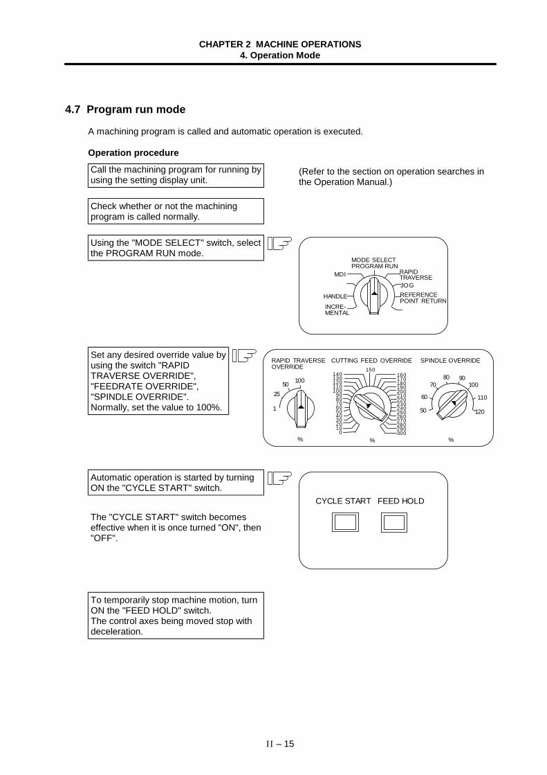
CHAPTER 2 MACHINE OPERATIONS4. Operation Mode
II – 15
4.7 Program run mode
A machining program is called and automatic operation is executed.
Operation procedure
Call the machining program for running byusing the setting display unit.
(Refer to the section on operation searches inthe Operation Manual.)
Check whether or not the machiningprogram is called normally.
Using the "MODE SELECT" switch, selectthe PROGRAM RUN mode.
MODE SELECTPROGRAM RUN
MDI
HANDLEINCRE-MENTAL
RAPIDTRAVERSEJOGREFERENCEPOINT RETURN
Set any desired override value byusing the switch "RAPIDTRAVERSE OVERRIDE","FEEDRATE OVERRIDE","SPINDLE OVERRIDE".Normally, set the value to 100%.
25
10050
1
%
160170180190200210220230240250260270280290300
150140130120110100
908070605040302010
0
100
50
60
7080 90
110
120
SPINDLE OVERRIDERAPID TRAVERSEOVERRIDE
CUTTING FEED OVERRIDE
% %
Automatic operation is started by turningON the "CYCLE START" switch.
The "CYCLE START" switch becomeseffective when it is once turned "ON", then"OFF".
CYCLE START FEED HOLD
To temporarily stop machine motion, turnON the "FEED HOLD" switch.The control axes being moved stop withdeceleration.
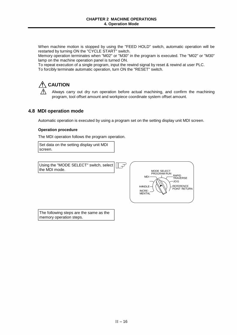
CHAPTER 2 MACHINE OPERATIONS4. Operation Mode
II – 16
When machine motion is stopped by using the "FEED HOLD" switch, automatic operation will berestarted by turning ON the "CYCLE START" switch.Memory operation terminates when "M02" or "M30" in the program is executed. The "M02" or "M30"lamp on the machine operation panel is turned ON.To repeat execution of a single program, input the rewind signal by reset & rewind at user PLC.To forcibly terminate automatic operation, turn ON the "RESET" switch.
CAUTION Always carry out dry run operation before actual machining, and confirm the machining
program, tool offset amount and workpiece coordinate system offset amount.
4.8 MDI operation mode
Automatic operation is executed by using a program set on the setting display unit MDI screen.
Operation procedureThe MDI operation follows the program operation.
Set data on the setting display unit MDIscreen.
Using the "MODE SELECT" switch, selectthe MDI mode.
The following steps are the same as thememory operation steps.
MODE SELECTPROGRAM RUN
MDI
HANDLEINCRE-MENTAL
RAPIDTRAVERSEJOG
REFERENCEPOINT RETURN
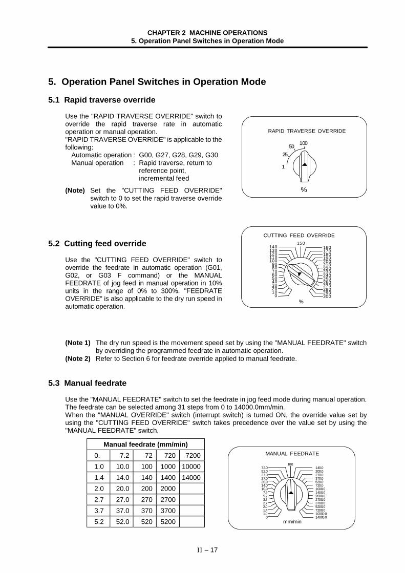
CHAPTER 2 MACHINE OPERATIONS5. Operation Panel Switches in Operation Mode
II – 17
5. Operation Panel Switches in Operation Mode
5.1 Rapid traverse override
Use the "RAPID TRAVERSE OVERRIDE" switch tooverride the rapid traverse rate in automaticoperation or manual operation."RAPID TRAVERSE OVERRIDE" is applicable to thefollowing:
Automatic operation : G00, G27, G28, G29, G30Manual operation : Rapid traverse, return to
reference point,incremental feed
(Note) Set the "CUTTING FEED OVERRIDE"switch to 0 to set the rapid traverse overridevalue to 0%.
5.2 Cutting feed override
Use the "CUTTING FEED OVERRIDE" switch tooverride the feedrate in automatic operation (G01,G02, or G03 F command) or the MANUALFEEDRATE of jog feed in manual operation in 10%units in the range of 0% to 300%. "FEEDRATEOVERRIDE" is also applicable to the dry run speed inautomatic operation.
(Note 1) The dry run speed is the movement speed set by using the "MANUAL FEEDRATE" switchby overriding the programmed feedrate in automatic operation.
(Note 2) Refer to Section 6 for feedrate override applied to manual feedrate.
5.3 Manual feedrate
Use the "MANUAL FEEDRATE" switch to set the feedrate in jog feed mode during manual operation.The feedrate can be selected among 31 steps from 0 to 14000.0mm/min.When the "MANUAL OVERRIDE" switch (interrupt switch) is turned ON, the override value set byusing the "CUTTING FEED OVERRIDE" switch takes precedence over the value set by using the"MANUAL FEEDRATE" switch.
Manual feedrate (mm/min) 0. 7.2 72 720 7200 1.0 10.0 100 1000 10000 1.4 14.0 140 1400 14000 2.0 20.0 200 2000 2.7 27.0 270 2700 3.7 37.0 370 3700 5.2 52.0 520 5200
%
CUTTING FEED OVERRIDE
160170180190200210220230240250260270280290300
150140130120110100
908070605040302010
0
10050
1
RAPID TRAVERSE OVERRIDE
25
%
mm/min
MANUAL FEEDRATE
10072.052.037.027.020.014.010.07.25.23.72.72.01.41.0
0
140.0200.0270.0370.0520.0720.01000.01400.02000.02700.03700.05200.07200.010000.014000.0
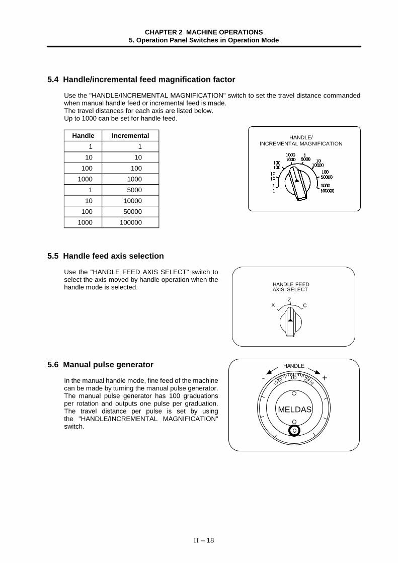
CHAPTER 2 MACHINE OPERATIONS5. Operation Panel Switches in Operation Mode
II – 18
5.4 Handle/incremental feed magnification factor
Use the "HANDLE/INCREMENTAL MAGNIFICATION" switch to set the travel distance commandedwhen manual handle feed or incremental feed is made.The travel distances for each axis are listed below.Up to 1000 can be set for handle feed.
Handle Incremental1 1
10 10100 100
1000 10001 5000
10 10000100 50000
1000 100000
5.5 Handle feed axis selection
Use the "HANDLE FEED AXIS SELECT" switch toselect the axis moved by handle operation when thehandle mode is selected.
5.6 Manual pulse generator
In the manual handle mode, fine feed of the machinecan be made by turning the manual pulse generator.The manual pulse generator has 100 graduationsper rotation and outputs one pulse per graduation.The travel distance per pulse is set by usingthe "HANDLE/INCREMENTAL MAGNIFICATION"switch.
HANDLE/INCREMENTAL MAGNIFICATION
00 +- 72
MELDAS
HANDLE
XZ
C
HANDLE FEEDAXIS SELECT
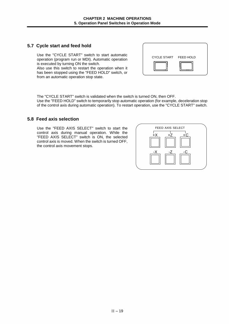
CHAPTER 2 MACHINE OPERATIONS5. Operation Panel Switches in Operation Mode
II – 19
5.7 Cycle start and feed hold
Use the "CYCLE START" switch to start automaticoperation (program run or MDI). Automatic operationis executed by turning ON the switch.Also use this switch to restart the operation when ithas been stopped using the "FEED HOLD" switch, orfrom an automatic operation stop state.
The "CYCLE START" switch is validated when the switch is turned ON, then OFF.Use the "FEED HOLD" switch to temporarily stop automatic operation (for example, deceleration stopof the control axis during automatic operation). To restart operation, use the "CYCLE START" switch.
5.8 Feed axis selection
Use the "FEED AXIS SELECT" switch to start thecontrol axis during manual operation. While the"FEED AXIS SELECT" switch is ON, the selectedcontrol axis is moved. When the switch is turned OFF,the control axis movement stops.
CYCLE START FEED HOLD
FEED AXIS SELECT
+X
-X
+Z
-Z
+C
-C
CHAPTER 2 MACHINE OPERATIONS6. Operation Switch Functions and Other Functions
II – 20
6. Operation Switch Functions and Other Functions
6.1 All axes machine lock
(1) By turning ON the "ALL AXES MACHINE LOCK" switch, NC commands can be executed formovement by manual operation and automatic operation without moving the machine.The current position display of the setting display unit is incremented.
(2) Either the command speed or the machine lock speed can be selected with the control parameter(#8105 Machine lock rapid) as the automatic operation speed during machine lock.• Command speed : Operation is carried out at the feedrate commanded in the program. Thus,
the operation time is the same as the actual machining time.• Machine lock speed : Movement commands are processed at high speed, and dwell time, etc.,
is ignored. Thus, program checks, etc., can be carried out quickly.(The machine lock rapid speed can be set in the parameter 2001.)
(3) If the "ALL AXES MACHINE LOCK" switch is changed over during automatic operation, the newswitch setting is validated when the automatic operation stops after the block being executed isterminated.
(4) In reference point returns (G28, G30), the axis is controlled to the middle point in a machine lockstate, but this state is ignored from the middle point to the reference point.
(5) If the "MACHINE LOCK" switch is changed over during manual operation, the new switch settingis validated after the operation stops once.
(6) M, S, T and B commands are executed as programmed.
(Note 1) Each coordinate value updated by the machine lock is preset to a value created based onthe machine value by resetting (including M02 and M30).
6.2 Each axis machine lock
By turning ON the "MACHINE LOCK" switch provided for each axis, machine lock will be applied onlyon the control axis (axes) turned ON. All matters, other than the machine lock for each axis, are thesame as all axes machine lock.
6.3 Display lock
(1) By turning ON the "DISPLAY LOCK" switch, the machine will move for the movement byautomatic operation and manual operation, but the current position display of the setting displayunit will not be incremented.The program coordinate system is updated.
(2) If the "DISPLAY LOCK" switch is changed over during automatic operation, the new switch settingis validated when the automatic operation stops after the block being executed is terminated.
(3) Use this switch when shifting the program zero point with the manual interrupt, without changingthe value on the display.
CHAPTER 2 MACHINE OPERATIONS6. Operation Switch Functions and Other Functions
II – 21
6.4 Miscellaneous function lock
(1) M, S, T, or B function execution can be ignored by turning ON the "MISCELLANEOUSFUNCTION LOCK" switch.
(2) The BCD output for the M, S, T and B functions is output, but the start signal is not output.(3) If the "MISCELLANEOUS FUNCTION LOCK" switch is changed over during command execution,
the new setting is validated when the automatic operation stops after the block being executed isterminated.
6.5 Single block
(1) When the "SINGLE BLOCK" switch is turned ON, automatic operation stops after the block beingexecuted is terminated. That is, automatic operation stops after one program block is executed.
(2) The single block stop point in the Fixed cycle mode is fixed according to the Fixed cycle.
6.6 Dry run
(1) When the "DRY RUN" switch is turned ON, the feedrate set by using the "MANUAL FEEDRATE"switch takes precedence over the programmed feedrate (F). If the operation panel has a "RAPIDTRAVERSE" switch that can be turned ON during a program command, the cutting feed clampspeed will be applied when the switch is turned ON.
6.7 Manual override
(1) When the "MANUAL OVERRIDE" switch is turned ON, the override value set by using the"FEEDRATE OVERRIDE" switch takes precedence over the value set by using the "MANUALFEEDRATE" switch.
(2) The override value also takes precedence over the dry run during automatic operation.(3) Manual override becomes effective immediately when the switch is turned ON.
6.8 Override cancel
(1) When the "OVERRIDE CANCEL" switch is turned ON, the programmed F command value takesprecedence over the override value set by using the "FEEDRATE OVERRIDE" switch.
(2) It is not effective for manual override.
CHAPTER 2 MACHINE OPERATIONS6. Operation Switch Functions and Other Functions
II – 22
6.9 Optional stop
(1) If M01 is programmed, the machine automatically stops by turning ON the "OPTIONAL STOP"switch. When the switch is OFF, M01 is ignored and the machine does not stop.
(2) The machine stops after the block including M01 is executed.
6.10 Optional block skip
When the "OPTIONAL BLOCK SKIP" switch is turned ON, a block which begins with a slash ( / ) isskipped; when the switch is OFF, the block is executed. This enables the operator to specify whetheror not a block beginning with a slash ( / ) code is executed.(Example) To work two parts as illustrated below, if the following program is prepared and work is
made by turning ON the "OPTIONAL BLOCK SKIP" switch, part 1 is provided; if work ismade by turning OFF the switch, part 2 is provided:
Program N1 G54; /N5 Z-40.;N2 G00X55.Z-20.; /N6 G75X30.P2.5;N3 G75R0.5; N7 Z-60.;N4 G75X30.P2.5Q0R0F0.2; N8 G75X30.P2.5;
N9 M02;
Part 1Switch ON
Part 2Switch OFF
N7 N5 N2N7 N2
CHAPTER 2 MACHINE OPERATIONS6. Operation Switch Functions and Other Functions
II – 23
6.11 Manual absolute
When the "MANUAL ABSOLUTE" switch is turned ON, the program coordinate system is updated bythe manual tool movement distance value. In other words, the coordinate system from the originalprogram is not shifted, even when the tool (machine) is moved manually.Thus in this case, the path returns to the one before manual movement when the automatic operationis started.If the switch is off, the program coordinate system is not updated by the manual tool movementdistance value. In other words, the coordinate system from the original program is shifted by the valuethat moved.
W
X
Z
Feed hold stop Path on program(absolute value command)
Manual interrupt(Program coordinate system is updated by travel distance.)
Starts after manual interrupt
Passes through the same path as program.
When "MANUAL ABSOLUTE" switch is ON
W
X
Z
Feed hold stopPath on program(absolute value command)
Manual interrupt(The program coordinate systemis not updated.)
Starts after manual interrupt
Path is shifted by manual interrupt value.(The zero point moves.)
When "MANUAL ABSOLUTE" switch is OFF
(Note) A "switch ON" status normally results when there is no "MANUAL ABSOLUTE" switch.Note that depending on the machine, a "switch OFF" status may result. Therefore, referto the specifications issued by the machine manufacturer.
CHAPTER 2 MACHINE OPERATIONS6. Operation Switch Functions and Other Functions
II – 24
6.12 Mirror image
By turning ON the MIRROR IMAGE switch for each axis, the mirror image can be executedindependently for each axis. This is a function used when carrying out symmetrical positioning of the axisby changing the sign of the command memory or MDI coordinate system, or to carry out cutting.The mirror image is applied on the incremental amount regardless of whether the absolute value orincremental value position command method is used.During an arc command, the rotation direction will reverse when the mirror image is ON only for one axis.
X
Z
Mirror image OFF path
Mirror image ON path
X axis mirrorimage ON
Program path
Workpiece zero point
If the command is an absolute value, the mirror image will be applied on the incremental amount from thecurrent position.
(Note 1) The mirror image is invalid for the reference point return.(Note 2) The mirror image is valid for the counter preset.
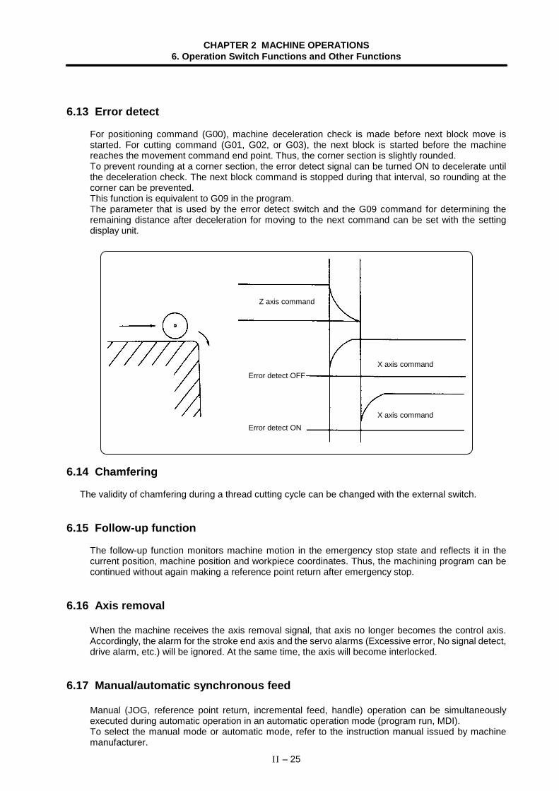
CHAPTER 2 MACHINE OPERATIONS6. Operation Switch Functions and Other Functions
II – 25
6.13 Error detect
For positioning command (G00), machine deceleration check is made before next block move isstarted. For cutting command (G01, G02, or G03), the next block is started before the machinereaches the movement command end point. Thus, the corner section is slightly rounded.To prevent rounding at a corner section, the error detect signal can be turned ON to decelerate untilthe deceleration check. The next block command is stopped during that interval, so rounding at thecorner can be prevented.This function is equivalent to G09 in the program.The parameter that is used by the error detect switch and the G09 command for determining theremaining distance after deceleration for moving to the next command can be set with the settingdisplay unit.
X axis command
X axis command
Error detect ON
Error detect OFF
Z axis command
6.14 Chamfering
The validity of chamfering during a thread cutting cycle can be changed with the external switch.
6.15 Follow-up function
The follow-up function monitors machine motion in the emergency stop state and reflects it in thecurrent position, machine position and workpiece coordinates. Thus, the machining program can becontinued without again making a reference point return after emergency stop.
6.16 Axis removal
When the machine receives the axis removal signal, that axis no longer becomes the control axis.Accordingly, the alarm for the stroke end axis and the servo alarms (Excessive error, No signal detect,drive alarm, etc.) will be ignored. At the same time, the axis will become interlocked.
6.17 Manual/automatic synchronous feed
Manual (JOG, reference point return, incremental feed, handle) operation can be simultaneouslyexecuted during automatic operation in an automatic operation mode (program run, MDI).To select the manual mode or automatic mode, refer to the instruction manual issued by machinemanufacturer.
CHAPTER 2 MACHINE OPERATIONS6. Operation Switch Functions and Other Functions
II – 26
6.18 Handle interruption
6.18.1 Outline
This section explains automatic handle interruption function, which enables the operator to interruptmovement using the manual handle in automatic modes (program run, MDI).(The automatic handle interruption function is an option.)
6.18.2 Interruptible conditions
(1) The automatic handle interrupt function allows the program to be interrupted from the manualhandle by selecting the manual handle mode in automatic mode selection (program run, MDI,etc.). However, the interrupt can not be generated from the manual handle when an automaticreference point return command (G28, G29, G30), thread cutting command (G33), or skipcommand (G31) has been executed or when tapping in the tapping cycle.
(2) If automatic mode such as program run or MDI is being selected even when an automaticoperation pause (including a block stop) is established, automatic handle interruption function isenabled.
(3) If the axis is moved during dwell (G04) command processing by using automatic handleinterruption function, the dwell count operation will stop. A check is made for that the axismovement has been completed, then the dwell count operation continues.
(4) Automatic handle interruption function is enabled even if automatic machine lock has been set. Ifmanual machine lock has been set, the machine does not move; it only updates the POSITIONdisplay. If manual machine lock has not been set, the machine moves by the interruption distanceby the manual handle and the POSITION display is updated.
(5) This function is disabled for an axis to which the interlock signal has been input or an axis, theinterruption direction of which is the soft limit.
CHAPTER 2 MACHINE OPERATIONS6. Operation Switch Functions and Other Functions
II – 27
6.18.3 Interruption effective axis
(1) Automatic handle interruption function is enabled only for axes to which manual handle axisselection has been input.
(2) Automatic handle interruption is enabled for a maximum of three axes. (The number of axes isrestricted by the number of handles.)
(3) One manual handle can only interrupt one axis with the automatic handle interruption function.
6.18.4 Axis movement speed resulting from interruption
(1) The movement speed of the axis for which handle interruption is executed, may exceed the rapidtraverse rate during rapid traverse command (G00) in automatic start. To prevent this, clamp theaxis. (The movement speed equals Automatic movement speed + Speed resulting from manualhandle interruption.)
(2) When cutting feed commands (G01, G02, G03) are issued during automatic start, the movementspeed of the axis for which the handle interruption is executed is clamped so it will not exceed thecutting feed clamp speed of that axis. (The movement speed equals Automatic movement speed+ Speed resulting from manual handle interruption.)
(3) If, during automatic start, manual handle interruption is executed, in the same direction, for theaxis that is moving at an external decelerating speed, the axis movement speed may exceed theexternal decelerating speed. To prevent this, clamp the axis. (The movement speed equalsAutomatic movement speed + Speed resulting from manual handle interruption.)
(4) If an attempt is made to execute interruption at a speed exceeding the clamp speed, the readingon the handle scale does not match the distance of interruption.
(5) The handle scale factor depends on the selected input of the manual handle/step scale factor.
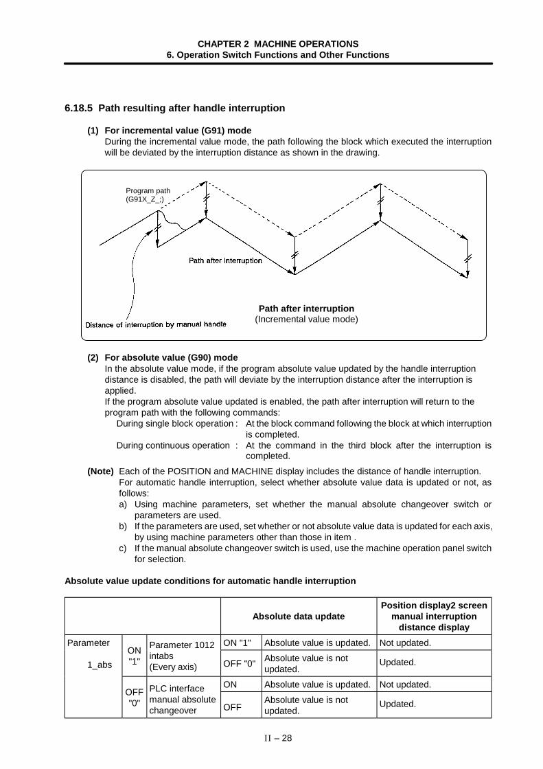
CHAPTER 2 MACHINE OPERATIONS6. Operation Switch Functions and Other Functions
II – 28
6.18.5 Path resulting after handle interruption
(1) For incremental value (G91) modeDuring the incremental value mode, the path following the block which executed the interruptionwill be deviated by the interruption distance as shown in the drawing.
Path after interruption(Incremental value mode)
Program path(G91X_Z_;)
(2) For absolute value (G90) modeIn the absolute value mode, if the program absolute value updated by the handle interruptiondistance is disabled, the path will deviate by the interruption distance after the interruption isapplied.If the program absolute value updated is enabled, the path after interruption will return to theprogram path with the following commands:
During single block operation : At the block command following the block at which interruptionis completed.
During continuous operation : At the command in the third block after the interruption iscompleted.
(Note) Each of the POSITION and MACHINE display includes the distance of handle interruption.For automatic handle interruption, select whether absolute value data is updated or not, asfollows:a) Using machine parameters, set whether the manual absolute changeover switch or
parameters are used.b) If the parameters are used, set whether or not absolute value data is updated for each axis,
by using machine parameters other than those in item .c) If the manual absolute changeover switch is used, use the machine operation panel switch
for selection.
Absolute value update conditions for automatic handle interruption
Absolute data updatePosition display2 screen
manual interruptiondistance display
ON "1" Absolute value is updated. Not updated.Parameter
1_absON"1"
Parameter 1012intabs(Every axis) OFF "0" Absolute value is not
updated.Updated.
ON Absolute value is updated. Not updated.OFF"0"
PLC interfacemanual absolutechangeover OFF
Absolute value is notupdated.
Updated.
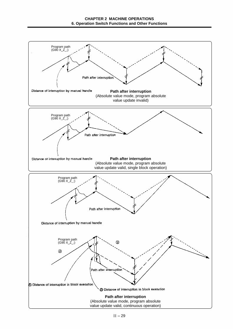
CHAPTER 2 MACHINE OPERATIONS6. Operation Switch Functions and Other Functions
II – 29
Path after interruption(Absolute value mode, program absolute
value update invalid)
Program path(G90 X_Z_;)
Path after interruption(Absolute value mode, program absolutevalue update valid, single block operation)
Program path(G90 X_Z_;)
Path after interruption(Absolute value mode, program absolutevalue update valid, continuous operation)
Program path(G90 X_Z_;)
Program path(G90 X_Z_;)
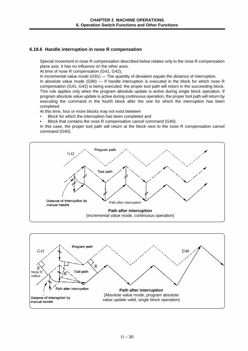
CHAPTER 2 MACHINE OPERATIONS6. Operation Switch Functions and Other Functions
II – 30
6.18.6 Handle interruption in nose R compensation
Special movement in nose R compensation described below relates only to the nose R compensationplane axis. It has no influence on the other axes.At time of nose R compensation (G41, G42);In incremental value mode (G91) — The quantity of deviation equals the distance of interruption.In absolute value mode (G90) — If handle interruption is executed in the block for which nose Rcompensation (G41, G42) is being executed, the proper tool path will return in the succeeding block.This rule applies only when the program absolute update is active during single block operation. Ifprogram absolute value update is active during continuous operation, the proper tool path will return byexecuting the command in the fourth block after the one for which the interruption has beencompleted.At this time, four or more blocks may not exist between• Block for which the interruption has been completed and• Block that contains the nose R compensation cancel command (G40).In this case, the proper tool path will return at the block next to the nose R compensation cancelcommand (G40).
Path after interruption(Incremental value mode, continuous operation)
Path after interruption
Path after interruption(Absolute value mode, program absolutevalue update valid, single block operation)
Nose Rradius
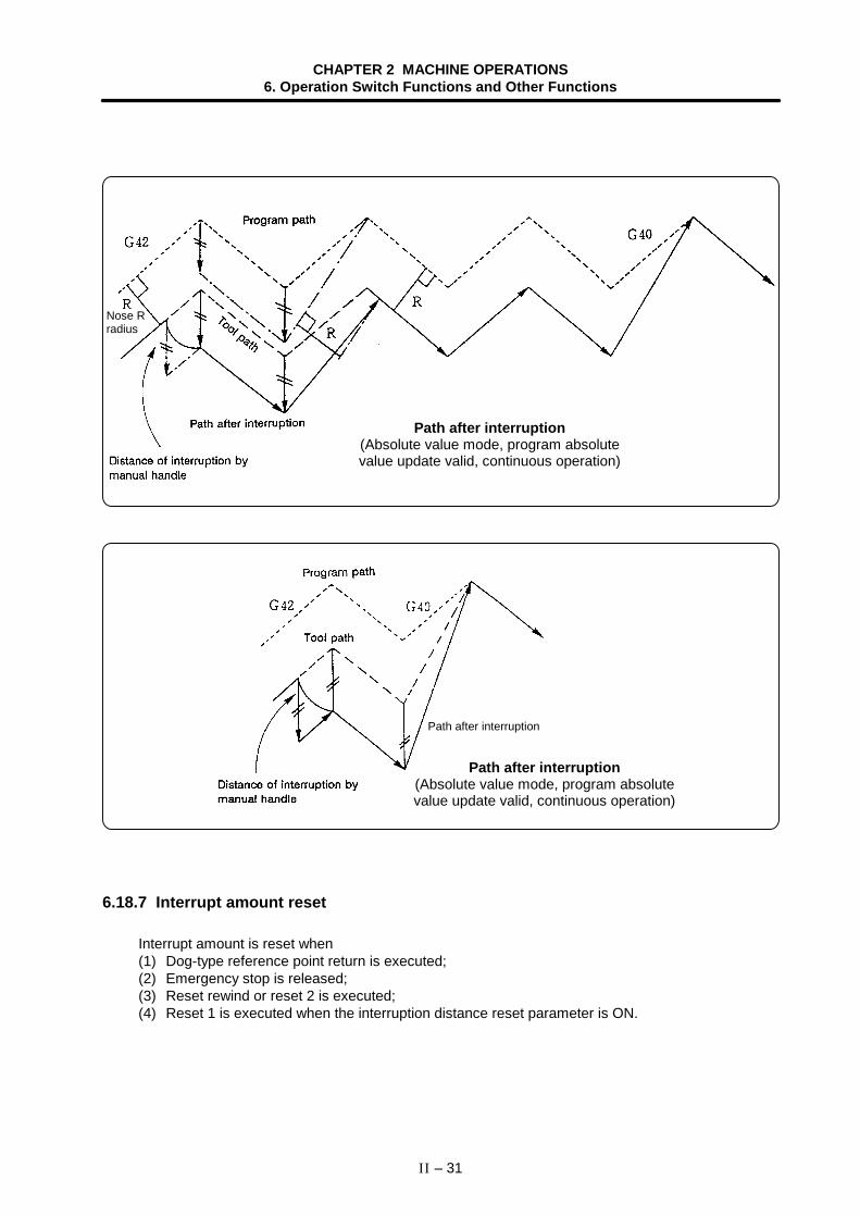
CHAPTER 2 MACHINE OPERATIONS6. Operation Switch Functions and Other Functions
II – 31
Path after interruption(Absolute value mode, program absolutevalue update valid, continuous operation)
Nose Rradius
Path after interruption(Absolute value mode, program absolutevalue update valid, continuous operation)
Path after interruption
6.18.7 Interrupt amount reset
Interrupt amount is reset when(1) Dog-type reference point return is executed;(2) Emergency stop is released;(3) Reset rewind or reset 2 is executed;(4) Reset 1 is executed when the interruption distance reset parameter is ON.
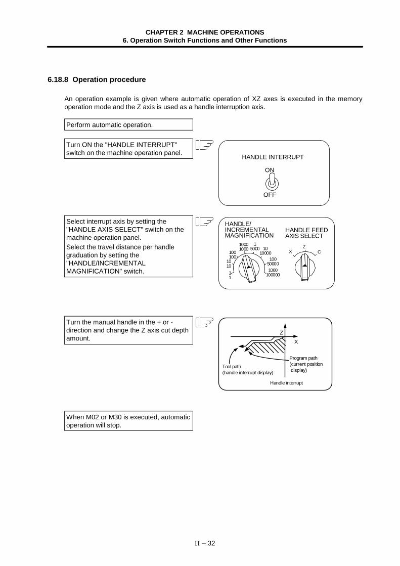
CHAPTER 2 MACHINE OPERATIONS6. Operation Switch Functions and Other Functions
II – 32
6.18.8 Operation procedure
An operation example is given where automatic operation of XZ axes is executed in the memoryoperation mode and the Z axis is used as a handle interruption axis.
Perform automatic operation.
Turn ON the "HANDLE INTERRUPT"switch on the machine operation panel.
ON
OFF
HANDLE INTERRUPT
Select interrupt axis by setting the"HANDLE AXIS SELECT" switch on themachine operation panel.Select the travel distance per handlegraduation by setting the"HANDLE/INCREMENTALMAGNIFICATION" switch.
1010000
11
1010
100100
10001000
15000
100500001000
100000
XZ
C
HANDLE FEEDAXIS SELECT
HANDLE/INCREMENTALMAGNIFICATION
Turn the manual handle in the + or -direction and change the Z axis cut depthamount. X
Z
Program path(current position display)
Handle interrupt
Tool path(handle interrupt display)
When M02 or M30 is executed, automaticoperation will stop.
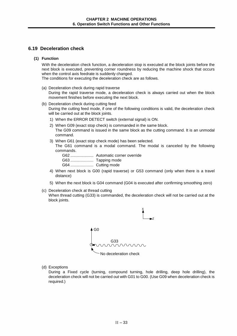
CHAPTER 2 MACHINE OPERATIONS6. Operation Switch Functions and Other Functions
II – 33
6.19 Deceleration check
(1) FunctionWith the deceleration check function, a deceleration stop is executed at the block joints before thenext block is executed, preventing corner roundness by reducing the machine shock that occurswhen the control axis feedrate is suddenly changed.The conditions for executing the deceleration check are as follows.
(a) Deceleration check during rapid traverseDuring the rapid traverse mode, a deceleration check is always carried out when the blockmovement finishes before executing the next block.
(b) Deceleration check during cutting feedDuring the cutting feed mode, if one of the following conditions is valid, the deceleration checkwill be carried out at the block joints. 1) When the ERROR DETECT switch (external signal) is ON. 2) When G09 (exact stop check) is commanded in the same block.
The G09 command is issued in the same block as the cutting command. It is an unmodalcommand.
3) When G61 (exact stop check mode) has been selected.The G61 command is a modal command. The modal is canceled by the followingcommands.
G62 ..................... Automatic corner overrideG63 ..................... Tapping modeG64 ..................... Cutting mode
4) When next block is G00 (rapid traverse) or G53 command (only when there is a traveldistance)
5) When the next block is G04 command (G04 is executed after confirming smoothing zero)
(c) Deceleration check at thread cuttingWhen thread cutting (G33) is commanded, the deceleration check will not be carried out at theblock joints.
X
Z
(d) ExceptionsDuring a Fixed cycle (turning, compound turning, hole drilling, deep hole drilling), thedeceleration check will not be carried out with G01 to G00. (Use G09 when deceleration check isrequired.)
No deceleration check
G33
G0
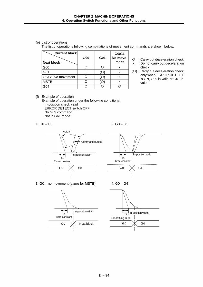
CHAPTER 2 MACHINE OPERATIONS6. Operation Switch Functions and Other Functions
II – 34
(e) List of operationsThe list of operations following combinations of movement commands are shown below.
Current block
Next blockG00 G01
G0/G1No move-
mentG00 ×G01 ( ) ×G0/G1 No movement ( ) ×MSTB ( ) ×G04
(f) Example of operationExample of operation under the following conditions:
In-position check validERROR DETECT switch OFFNo G09 commandNot in G61 mode
1. G0 – G0 2. G0 – G1
TsTime constant
G0 G0 G0 G1
Actual
Command output
In-position widthTs
Time constant
In-position width
3. G0 – no movement (same for MSTB) 4. G0 – G4
TsTime constant
In-position width
G0 Next block
Ts In-position width
G0 G4
Smoothing zero
: Carry out deceleration check× : Do not carry out deceleration
check( ) : Carry out deceleration check
only when ERROR DETECTis ON, G09 is valid or G61 isvalid.
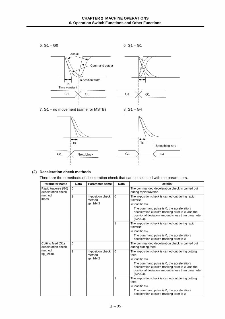
CHAPTER 2 MACHINE OPERATIONS6. Operation Switch Functions and Other Functions
II – 35
5. G1 – G0 6. G1 – G1
Actual
Command output
TsTime constant
In-position width
G1 G0 G1 G1
7. G1 – no movement (same for MSTB) 8. G1 – G4
G1 Next block
Ts
G1 G4
TsSmoothing zero
(2) Deceleration check methodsThere are three methods of deceleration check that can be selected with the parameters.
Parameter name Data Parameter name Data Details0 The commanded deceleration check is carried out
during rapid traverse.0 The in-position check is carried out during rapid
traverse.<Conditions>
The command pulse is 0, the acceleration/deceleration circuit's tracking error is 0, and thepositional deviation amount is less than parameter(SV024).
Rapid traverse (G0)deceleration checkmethodinpos
1 In-position checkmethodsp_1/bit3
1 The in-position check is carried out during rapidtraverse.<Conditions>
The command pulse is 0, the acceleration/deceleration circuit's tracking error is 0.
0 The commanded deceleration check is carried outduring cutting feed.
0 The in-position check is carried out during cuttingfeed.<Conditions>
The command pulse is 0, the acceleration/deceleration circuit's tracking error is 0, and thepositional deviation amount is less than parameter(SV024).
Cutting feed (G1)deceleration checkmethodsp_1/bit0
1 In-position checkmethodsp_1/bit2
1 The in-position check is carried out during cuttingfeed.<Conditions>
The command pulse is 0, the acceleration/deceleration circuit's tracking error is 0.
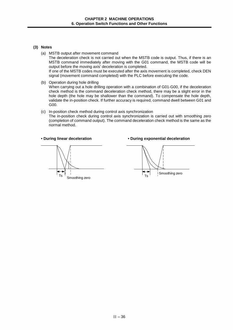
CHAPTER 2 MACHINE OPERATIONS6. Operation Switch Functions and Other Functions
II – 36
(3) Notes(a) MSTB output after movement command
The deceleration check is not carried out when the MSTB code is output. Thus, if there is anMSTB command immediately after moving with the G01 command, the MSTB code will beoutput before the moving axis' deceleration is completed.If one of the MSTB codes must be executed after the axis movement is completed, check DENsignal (movement command completed) with the PLC before executing the code.
(b) Operation during hole drillingWhen carrying out a hole drilling operation with a combination of G01-G00, if the decelerationcheck method is the command deceleration check method, there may be a slight error in thehole depth (the hole may be shallower than the command). To compensate the hole depth,validate the in-position check. If further accuracy is required, command dwell between G01 andG00.
(c) In-position check method during control axis synchronizationThe in-position check during control axis synchronization is carried out with smoothing zero(completion of command output). The command deceleration check method is the same as thenormal method.
• During linear deceleration • During exponential deceleration
Ts Smoothing zero TsSmoothing zero
CHAPTER 2 MACHINE OPERATIONS6. Operation Switch Functions and Other Functions
II – 37
6.20 Miscellaneous command high-speed output
The miscellaneous command high-speed output function is a miscellaneous command completionmethod, which after outputting the miscellaneous command proceeds to the next block without waitingfor the completion signal from the PLC.Using this function, the processing time per miscellaneous function can be shortened compared to theconventional method.
(1) Detailed explanationIf a miscellaneous command (M) is commanded from the machining program while themiscellaneous command high-speed output function is valid, the miscellaneous command codedata and miscellaneous command strobe signal are output to the PLC. The NC finishes themiscellaneous command process when the miscellaneous command strobe signal is output.The operation sequence for when the miscellaneous command high-speed output function is valid isshown below.
Machining program
Comm and code
MF
FIN
NC PLCsignal
PLC NC
M comm and Next block
M comm and
When the miscellaneous command is output by the miscellaneous command high-speed outputfunction, if the previous miscellaneous command (M, S, T, B) has not been completed, the currentcommand code and strobe signal will be output after waiting for the previous miscellaneouscommand to complete.
• Case for waiting for miscellaneous command output (using FIN1)
Machining program
Command code
MF
FIN1
NC PLCsignal
PLC NC
M comm and Next block
M comm and
Previous strobe Current strobe
CHAPTER 2 MACHINE OPERATIONS6. Operation Switch Functions and Other Functions
II – 38
• Case for waiting for miscellaneous command output (using FIN2)
Machining program
Command code
MF
FIN2
NC PLCsignal
PLC NC
M command Next block
M comm and
Previous strobe Current strobe
If FIN2 is used for the completion signal while the miscellaneous command high-speed outputfunction is valid (when the option is valid), the NC will turn the strobe signal and FIN2 signal OFF atoutput the rising edge of FIN2.
When the movement command and miscellaneous command are commanded in the same block, ifthe previously commanded miscellaneous command is not completed, the axis movement start andmiscellaneous command output will not be carried out simultaneously.
• For M∗∗∗∗∗∗∗∗ ; (using FIN1) G00 X_M@@;
Machining program
X axis movement
Command code
MF
FIN1
NC PLCsignal
PLC NC
M ∗∗ G00 X_M@ @ ;
M@@
M ∗∗ strobe M@ @ strobe
M ∗∗
Whether to carry out the commanded miscellaneous command with the high-speed output orwhether to proceed to the next block after waiting for completion is set with the parameters.The number of miscellaneous commands for which high-speed output is carried out is 256commands (M0 to M255) for the M command.If a miscellaneous command for high-speed output and a miscellaneous command, which waits forthe completion signal from the PLC, are commanded in the same block, the next block will beproceeded to after waiting for the completion signal from the PLC.The program command format used when the miscellaneous command high-speed output functionis valid is the same as the conventional command format.The miscellaneous command high-speed output function is invalid to M independent commands(M00, M01, M02, M30).
(2) Relation with other functionsRelation with miscellaneous command completion wait suppression (#3003 bit1)When the miscellaneous command completion wait suppression is ON (#3003 bit1 ON), allmiscellaneous command will proceed to the next block without waiting for the completion signal fromthe PLC regardless of whether this function is valid or invalid.
CHAPTER 2 MACHINE OPERATIONS6. Operation Switch Functions and Other Functions
II – 39
6.21 Rapid traverse constant inclination acceleration/deceleration
This function carries out acceleration/deceleration at a constant inclination during the linear acceleration/deceleration in the rapid traverse mode.The constant inclination acceleration/deceleration method is effective in improving the cycle timecompared to the conventional method.
(1) Detailed explanationThe rapid traverse constant inclination acceleration/deceleration is valid only during a rapid traversecommand. It is also valid only when the rapid traverse command's acceleration/deceleration mode islinear acceleration or linear deceleration.The acceleration/deceleration patterns when rapid traverse constant inclination acceleration/deceleration is used is shown in the next section.
(a) When interpolation distance is longer than acceleration/deceleration distance
rapid
Ts
T
LNext block
TsTd
θ
(b) When interpolation distance is shorter than acceleration/deceleration distance
rapid
θTs
T
Next block
Td
The time required for the command deceleration check during rapid traverse constant inclinationacceleration/deceleration is the rapid traverse deceleration check time for each axis, determined bythe simultaneously commanded axes' rapid traverse rate, rapid traverse acceleration/decelerationtime constant and interpolation distance. The longest of the axis times is used.When two-axis simultaneous interpolation (linear interpolation) is carried out during rapid traverseconstant inclination acceleration/deceleration, the acceleration/deceleration time of each axis will bethe acceleration/deceleration time of each axis determined by the simultaneously commanded axes'rapid traverse rate, rapid traverse acceleration/deceleration time constant and interpolation distance.The longest of the axis times is used. Thus, linear interpolation is carried out even when theacceleration/deceleration time constant for each axis is different.
rapid: Rapid traverse rateTs : Acceleration/deceleration
time constantTd : Command deceleration
check timeθ : Acceleration/deceleration
inclinationT : Interpolation timeL : Interpolation distance
Td = + (0 to 14ms)T2
θ = tan–1 ( )rapid
Ts
T = 2 × Ts × L/rapid
rapid: Rapid traverse rateTs : Acceleration/deceleration
time constantTd : Command deceleration
check timeθ : Acceleration/deceleration
inclinationT : Interpolation timeL : Interpolation distance
T= + TsLrapid
Td = Ts + (0 to 14ms)
θ = tan–1 ( )rapid
Ts
CHAPTER 2 MACHINE OPERATIONS6. Operation Switch Functions and Other Functions
II – 40
(c) For two-axis simultaneous interpolation (Linear interpolation Tsx < Tsz, LX ≠≠≠≠ Lz>)
rapidX
θxTsx
Tx
Lx Next block
TsxTdx
X axis
rapidZ
θzTsz
Tz
Lz Next block
Tsz
Tdz
Z axis
The program format for G0 (rapid traverse command) when rapid traverse constant inclinationacceleration/deceleration is carried out is the same as when this function is invalid (constant timeacceleration/deceleration).This function is valid only for the G0 (rapid traverse) command.
(2) Relation with other functionsRelation with override and dry runIf the rapid traverse rate changes because of override or dry run, the acceleration/decelerationinclination will change, and constant inclination acceleration/deceleration will not be carried out.
rapid
θ
T s
Next block
rapid
T s
Next block
Override100%
Override50%
When Tsz > Tsx, Tdz is largerthan Tdx, and becomes theTd = Tdz for this block.

CHAPTER 3 MAINTENANCE
CHAPTER 3 MAINTENANCE1. Confirming the Operation
III – 1
1. Confirming the Operation
1.1 Confirming the axis movement direction
(1) Confirming the axis operation with the handle modeEach axis is moved in the handle mode, and the movement of the axis corresponding to the handlerotation direction (+, − ) is confirmed.When the axis is moved in the opposite direction, the setting in the Axis specification parameter"1007 ccw" is confirmed, and changed from "0" to "1" or vice versa.
(2) Confirming the movement operation with the JOG modeThe axis is moved in the JOG mode, and the axis operation following the command direction isconfirmed.(Note 1) If the axis stability is poor when the axis is moved in the handle or JOG mode, first adjust
the stability of the drive system as shown on the following sections.
1.2 Confirming the limit switch operation
(1) Confirming the stroke end operation
1) Turn ON the plus side stroke end limit switch by moving the axis in the plus direction using thehandle feed or JOG feed.
• The axis must stop when the limit switch kicks the dog.• The stroke end alarm must be displayed in the Alarm message screen of the setting display
unit.• The axis must not move when a plus direction movement command is issued again.• The axis must move in the minus direction when a minus command is issued.
2) Turn ON the minus side stroke end limit switch by moving the axis in the minus direction.• The axis must stop when the limit switch kicks the dog.• The stroke end alarm must be displayed in the Alarm message screen of the setting display
unit.• The axis must not move when a minus direction movement command is issued again.• The axis must move in the plus direction when a plus command is issued.
(2) Confirming the reference point return operation1) Decrease the reference point return speed using the RAPID TRAVERSE OVERRIDE switch.2) Carry out a reference point return.3) Confirm that a deceleration stop is carried out once at the near- point dog.4) After executing step 3), confirm that the movement is toward the reference point.
If the reference point return direction differs, the parameter setting is incorrect.5) After moving in the reference point return direction and stepping on the dog, confirm that the axis
reaches the reference point within 10 to 100mm. Also confirm that the reference point reachedsignal is output, and the reference point reached lamp of the operation panel is lit.
6) Confirm whether the axis position is that of the machine reference point when the referencepoint reached signal is output.
7) Display the Amp monitor (servo unit) screen of the setting display unit, and confirm the gridamount display. • Confirm that the grid amount is approx. 1/2 of the grid spacing.
8) Refer to the section "3. Adjusting the Dog-type Reference Point Return" if the reference pointposition must be changed or adjusted.
9) For absolute position detection, refer to the section "Absolute Position Setting screen" in theinstruction manual.
CHAPTER 3 MAINTENANCE2. Confirming the Drive Section
III – 2
2. Confirming the Drive Section(1) Confirming the servo parameters
Confirm the servo parameters after setup and confirmation of the wiring, etc.1) Confirm that the servo parameter data (machine specifications, servo system specifications) is
correct.The suitability of the amplifier type, control method, motor end detector, machine end detectorand motor related to the servo system can be confirmed by referring to the Amp monitor (servounit) screen.
2) Confirm that the correct parameters are set for the motor used.
(2) Adjusting the servo parametersThe following three servo parameters are generally used to adjust the drive section system. Whenchanging this parameter data, do so one or two increments at a time. Do not change the parametervalue greatly all at once.1) PGN1: Position loop gain Standard value: 33
While this value is usually set to 33, it is lowered to approx. 25 when overshooting in aclosed loop system. Set this parameter as common for all axes.
2) VGN : Speed loop gain Standard value: 150Raising this value increases the responsiveness. (Max. value: 250)
3) VIA : Speed loop advance compensation Standard value: 1364Raising this value increases the responsiveness.
CHAPTER 3 MAINTENANCE3. Adjusting the Dog-type Reference Point Return
III – 3
G28 Rapid traverse rate
3. Adjusting the Dog-type Reference Point ReturnThe relative position detection and absolute position detection type position detection systems areavailable. The methods of returning to the reference point include the dog-type reference point return andthe dogless-type reference point return.The method of adjusting the dog-type reference point return using the relative position detection isdescribed in this section.
3.1 Dog-type reference point return
(1) Reference point return operationWhen the dog-type reference point return is executed, the machine will move at the commandedspeed. When the near-point detection limit switch kicks the near-point dog (when the near-pointdetection signal turns OFF), the machine decelerates to a stop. After decelerating to a stop, themachine moves at the creep speed, and positions to the first grid point after leaving the near-pointdog.This grid point is called the electrical zero point. Normally, this electrical zero point position is thereference point.For the reference point return using the relative position detector, the first return after turning thepower ON is carried out with the dog-type reference point return. The second and following returnsare carried out with high-speed reference point return. High-speed reference point return is afunction that directly positions to the reference point saved in the memory without decelerating at thenear-point dog.If reference point return has not been executed even once after turning ON the power while usingrelative position detection, an alarm will occur when movement commands other than G28 areexecuted.
Grid spacing
Creep speed
Reference point return direction
Grid amountNear-point detectionlimit switch
Near-point dog
Electrical zero point
Grid point
Reference point (Position returned to with the zero point return command)
CHAPTER 3 MAINTENANCE3. Adjusting the Dog-type Reference Point Return
III – 4
(2) Reference pointThe reference point is the point positioned to when the dog-type reference point return is executed.Note that a separate setting method is used for the absolute position detection.The reference point is the point positioned to with the manual reference point return and G28command in the machining program.Using parameters, the reference point can be shifted from the electrical zero point position.
(3) Grid pointThe position detector has a Z-phase that generates one pulse per rotation. The 0-point position ofthis Z-phase is the grid point. Thus, there is a grid point per rotation of the position detector, and themachine has many grid points at a set pitch.The grid point can be set per grid spacing by setting the grid spacing (Zero point return parameter2104 grspc). Thus, multiple grid points can be set per detector rotation.
(4) Grid spacingThe distance between the grid points is the grid spacing. The grid spacing can be set in mm(millimeter) units in the Zero point return parameter 2104 grspc.
(5) Grid amountThe grid amount expresses the distance from when the near-point detection limit switch leaves thenear-point dog and reaches the grid point (electrical zero point) when the dog-type reference pointreturn is executed.The grid amount can be confirmed with "Grid amnt" on the Amp monitor (servo unit) screen of thesetting display unit.After setting the grid mask, the grid amount shows the distance from the grid mask OFF to the gridpoint.
(6) Basic machine coordinate system zero pointThe basic machine coordinate system is a coordinate system that expresses a position decidedcharacteristically for the machine.The following positions are expressed with the machine coordinate system.
• No. 1 to No. 4 reference point position• Workpiece coordinate system zero point position• Stored stroke limit position
Usually, the machine coordinate zero point position is the same as the reference point position, but itcan be shifted with the parameters.
CHAPTER 3 MAINTENANCE3. Adjusting the Dog-type Reference Point Return
III – 5
3.2 Reference point return parameters
(1) Reference point return operation and parameter related drawing
Grid spacing
2108 #1_rfp #1 Reference point
The grid point betweenthe grid mask is not theelectrical zero point.
2104 grspc2103 G28sft
2105 grmask
The first grid at theend of the grid mask isthe electrical zeropoint.
The grid amount isdisplayed on the"ALM/DIAG" "SERVOMONITOR" screen.
Referencepoint shiftamount
Gridamount
Grid maskamount
Grid maskNear-point dogGrid point
Electrical zero point
Basic machine coordinatesystem zero point
Reference point(Position returned to withthe zero point returncommand)2102 G28crp Approach speed
2106 dir (−) Reference point return direction2101 G28rapG28 rapid traverse rate
CHAPTER 3 MAINTENANCE3. Adjusting the Dog-type Reference Point Return
III – 6
(2) G28 rapid traverse rate (2101 G28rap)This parameter designates the feedrate for dog-type reference point return in manual operation andautomatic operation.The feedrate during high-speed reference point return will be the rapid traverse rate (Axisspecification parameter 2001 rapid).
(3) G28 approach speed (2102 G28crp)This parameter sets the approach speed (creep speed) to the reference point after decelerating to astop by the near-point dog detection. The creep speed is accelerated and decelerated in steps, so ifthe speed is fast, mechanical shock, etc., could occur.The creep speed should be set between 100 and 300mm/min., and within 500mm/min. at thefastest.
(4) Reference point shift amount (2103 G28sft)This parameter can set the shift amount for shifting the reference point from the electrical zero point.The shift direction can be set only in the reference point return direction.If the reference point shift amount is "0", the grid point (electrical zero point) will be the referencepoint.
(5) Grid spacing (2104 grspc)This parameter sets the distance between grids.The normal grid spacing is the ball screw pitch (Servo parameter 2218 PIT) value or the movementamount per motor rotation set as a mm (millimeter) unit.To make the grid spacing smaller, set a divisor of the grid spacing.
Calculation expression for movement amount per motor rotation
• When linear feed mechanism is ball screw
Movement amount per motor rotation = Motor side gear ratioMachine side gear ratio
∗ Ball screw pitch
• When linear feed mechanism is rack and pinionMovement amount per motor rotation =
Motor side gear ratioMachine side gear ratio
∗ No. of pinion gear teeth ∗ Rack pitch
• For rotation axis
Movement angle per motor rotation = Motor side gear ratioMachine side gear ratio
∗ 360
N = PC1PC2
∗ PITN = Movement amount per motor rotationPC1 = Motor side gear ratioPC2 = Machine side gear ratioPIT = Ball screw pitch
CHAPTER 3 MAINTENANCE3. Adjusting the Dog-type Reference Point Return
III – 7
(6) Grid mask amount (2105 grmask)The electrical zero point is the first grid point after the dog is stepped.If the grid point is at the position where the near-point dog is stepped, the electrical zero point will bethe grid point at the position where the dog is stepped because of the delay of the limit switchoperation. Thus, the next grid point will be applied, or in the end, the reference point position may bedeviate by the amount of the grid spacing.Thus, the position that the dog is stepped must be at the approximate center of the grid spacing.
The electrical zero pointwill change depending onthe limit switch delay.
Dog
Reference point
Adjustments can be made by changing the near-point dog position or by setting the grid maskamount.Setting the grid mask has the same effect as lengthening the near-point dog.If the grid amount is near the grid spacing or 0, the grid point will be at the position that the near-pointdog is stepped, so set a grid mask.The grid mask amount is set so that the grid amount is one-half of the grid spacing.The grid mask amount can be set only in the reference point return direction.The grid amount and grid spacing can be confirmed on the Amp monitor (servo unit) screen.
Grid mask amount calculation expression
(a) When Grid spacing2
< Grid amount Grid mask amount = Grid amount − Grid spacing2
Reference point (Position returned to with the zero point return command)
Electrical zero point
Grid amount
Grid maskamount
Grid spacing2
Grid maskNear-point dog
CHAPTER 3 MAINTENANCE3. Adjusting the Dog-type Reference Point Return
III – 8
(b) When Grid spacing2
> Grid amount Grid mask amount = Grid amount + Grid spacing2
Grid amount
Grid mask amount
Grid amount after grid mask is set
2Grid spacing
Grid mask
Reference point before grid mask isset
Reference point after gridmask is set
Near-point dog
This will not be the electrical zero point due to the grid mask.
(7) Reference point return direction (2106 dir (−−−−))This parameter sets the direction to move after the limit switch kicks the dog causing a decelerationstop during dog-type reference point return. The direction is either positive "0" or negative "1".If the reference point position is in the positive direction from the near-point dog, set "0".If the reference point position is in the negative direction from the near-point dog, set "1".
(a) When reference point return direction is positive (+)
Reference point
Dog
To move in− direction
To move in+ direction
– +
(b) When reference point return direction is negative (−−−−)
Reference point
Dog
To move in− direction
To move in+ direction
– +
CHAPTER 3 MAINTENANCE3. Adjusting the Dog-type Reference Point Return
III – 9
(8) Axis with no reference point (2107 noref)"0" is set for the axis to carry out dog-type reference point return and the axis for absolute positiondetection."1" is set for the axis that does not carry out reference point return during relative position detection.
(9) Reference point position (2113 #1_rfp to 2116 #4_rfp)This parameter is set when the basic machine coordinate system zero point position is to be shiftedfrom the reference point position.When "0" is set, the reference point position will be the position of the basic machine coordinatesystem zero point.#n_rfp sets the reference point position from the basic machine coordinate system zero pointposition as a basic machine coordinate system coordinate value.
3.3 Dog-type reference point return adjustment procedures
Adjust the dog-type reference point return with the following steps.
(1) Set the zero point return parameter.Set the reference point shift amount to "0".Set the grid mask amount to "0".
(2) Turn the power OFF and ON, and then execute reference point return.(3) Display the Amp monitor (servo unit) screen on the setting display unit.
The grid spacing and grid amount values can be read.(4) Calculate the grid mask amount with the grid mask amount calculation method.(5) Display the Z-point rtn param screen.
Set the grid mask amount.(6) Turn the power OFF and ON, and then execute reference point return.(7) Display the Amp monitor (servo unit) screen on the setting display unit.
The grid spacing and grid amount values can be read.If the grid amount value is approx. half of the grid spacing, the grid mask amount has been correctlyset.If the value is not approx. half, repeat the procedure from step (1).
(8) Set the reference point shift amount.(9) Turn the power OFF and ON, and then execute reference point return.(10) Set #1_rfp.
CHAPTER 3 MAINTENANCE4. Absolute Position Detection
III – 10
4. Absolute Position Detection
4.1 Absolute position detection system
(1) OutlineOnce the absolute position is detected, the absolute position detection function basically enablesautomatic operation without losing the absolute position even if the power is turned OFF and ON.This function is reliable as it carries out a mutual check of the feedback amount from the detector,and checks the absolute position unique to the machine, etc.There are two methods of establishing (initializing) the absolute position.
(a) Dog-type absolute position detectionThe absolute position origin point is established by executing dog-type reference point return.
(b) Dogless-type absolute position detectionBy initializing the zero point at the machine end or a random point, the absolute position originpoint can be established without using a dog This eliminates the need to install a dog or limitswitch on the machine, and simplifies the machine structure.The following six methods can be used to initialize the zero point with the dogless-type detection.
Dog-less type method Origin point type Adjustmentprocedures reference
Random point type 4.4.1Screen operationmethod Grid point type 4.4.2
Random point type 4.4.3
Machine endstoppermethod Automatic
dogless-type Grid point type 4.4.4Random point type 4.5.1Marked point alignment method
(Screen operation method) Grid point type 4.5.2
Machine end stopper method(Screen operation method)
The zero point is initialized by pushing against themachine end with manual movement.Operations are required on the "Abs posn set" screen.Mode: JOG, handle, step, manual random feed mode
Machine end stopper method(Automatic dogless-type)
The zero point is initialized by pushing against themachine end with manual movement.Screen operations are not required.Mode: Automatic dogless reference point return mode
Marked point alignment method(Screen operation method)
The zero point is initialized by making a mark at arandom point within the machine's moveable range, andmoving manually to the mark position.Operations are required on the "Abs posn set" screen.Mode: JOG, handle, step, manual random feed mode
CHAPTER 3 MAINTENANCE4. Absolute Position Detection
III – 11
Random point typeThe machine end or marked position is used as theabsolute position origin point (the point unique for thedogless-type, refer to section 4.1(2)).
Grid point type
The machine end or a grid point on the detector near themarked position is used as the absolute position originpoint (the point unique for the dogless-type, refer tosection 4.1(2)).
The validity and method of the absolute position detection system can be selected withparameters for each axis.The servo amplifier and detector must have absolute position detection specifications.
(2) Absolute position detection system coordinate systemWhen using the dogless-type, the machine end or marked point is used as the absolute positionorigin point and the basic machine coordinate system zero point is set at the position designated for"1202 Ref position offset" on the Abs posn set screen.
1202
2113#1_rfp
Absolute positionorigin point(For dogless only)
Ref position offset
1st reference point
Basic machine coordinate systemzero point (G53 zero point)
With the dog-type, there is no absolute position origin point. The 1st reference point is the reference,and the basic machine coordinate system zero point is determined by the "2113 #1_rfp" value.
(3) Reference point return operation after establishing absolute positionThe reference point return operation is carried out in the following manner.
1011 abson value Manual reference point return G28 automatic referencepoint return
Dog-type absoluteposition detection(abson: 1)
The dog-type can be selected with theaxis parameter "Manual dog type" eachtime.Manual dog-type: 0 High-speed method
1: Per time dog-type
High-speed method
Dogless-type absoluteposition detection(abson: 2)
High-speed method High-speed method
CHAPTER 3 MAINTENANCE4. Absolute Position Detection
III – 12
4.2 Starting up absolute position detection
(1) Operation when initialization is not completeIf the zero point has not been initialized, or when the absolute position has been lost afterinitialization, an error or warning will occur.In this state, the coordinate system will not be set, so limits will be applied in each mode. Thus, carryout zero point initialization to establish the coordinate system.
Absolute position detection methodOperation mode
Dog-type Dogless-typeGeneral movementcommands Not possible (Note 1) Not possible (Note 2)
Memory, MDIG28 Possible Not possible (Note 2)
JOG, handle, step, manual random feed Possible PossibleZero point return Possible Not possible
Automatic dogless reference point return Not possiblePossible
(Only machine endstopper method)
(Note 1) The program error "P430 Zero return not completed" will occur.(Note 2) Automatic start is not possible.
(2) Selecting the zero point initialization methodSelect the zero point initialization method with the following parameters.
1011 abson(Base axis param screen)
0: Absolute position detection invalid (execute dog-type each time power is turned ON)
1: Absolute position detection (dog-type)2: Absolute position detection (dogless-type)
1205 No stopper(Abs posn set screen)
0: Machine end stopper method1: Marked point alignment method
1208 Ref posn type(Abs posn set screen)
0: Random point typeThe machine end or marked point is used as theabsolute position origin point.
1: Grid point typeA grid point near the machine end or near themarked position is used as the absolute positionorigin point.
(3) Setting the other machine parametersThe following parameters must be set in addition to those in item (2).
2104 grspc(Z-point rtn param screen) Set the grid interval as mm unit.
2217 SPEC∗(Servo param screen)
Set the absolute position detection valid bit (bit 7) to"1".Set as a hexadecimal.
(4) Initializing the zero pointRefer to the explanations in sections 4.3 to 4.5, and initialize the zero point.
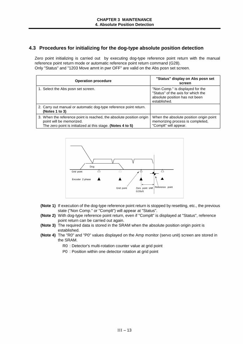
CHAPTER 3 MAINTENANCE4. Absolute Position Detection
III – 13
4.3 Procedures for initializing for the dog-type absolute position detection
Zero point initializing is carried out by executing dog-type reference point return with the manualreference point return mode or automatic reference point return command (G28).Only "Status" and "1203 Move amnt in pwr OFF" are valid on the Abs posn set screen.
Operation procedure "Status" display on Abs posn setscreen
1. Select the Abs posn set screen. "Non Comp." is displayed for the"Status" of the axis for which theabsolute position has not beenestablished.
2. Carry out manual or automatic dog-type reference point return.(Notes 1 to 3)
3. When the reference point is reached, the absolute position originpoint will be memorized.The zero point is initialized at this stage. (Notes 4 to 5)
When the absolute position origin pointmemorizing process is completed,"Complt" will appear.
Grid point
Dog
Encoder Z-phase
Grid point Zero point shiftG28sft
Reference point
(Note 1) If execution of the dog-type reference point return is stopped by resetting, etc., the previousstate ("Non Comp." or "Complt") will appear at "Status".
(Note 2) With dog-type reference point return, even if "Complt" is displayed at "Status", referencepoint return can be carried out again.
(Note 3) The required data is stored in the SRAM when the absolute position origin point isestablished.
(Note 4) The "R0" and "P0" values displayed on the Amp monitor (servo unit) screen are stored inthe SRAM.
R0 : Detector's multi-rotation counter value at grid pointP0 : Position within one detector rotation at grid point
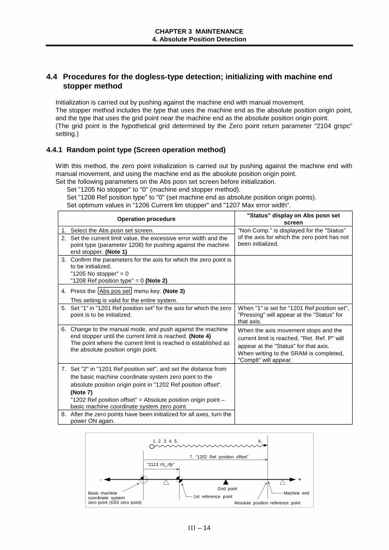
CHAPTER 3 MAINTENANCE4. Absolute Position Detection
III – 14
4.4 Procedures for the dogless-type detection; initializing with machine endstopper method
Initialization is carried out by pushing against the machine end with manual movement.The stopper method includes the type that uses the machine end as the absolute position origin point,and the type that uses the grid point near the machine end as the absolute position origin point.(The grid point is the hypothetical grid determined by the Zero point return parameter "2104 grspc"setting.)
4.4.1 Random point type (Screen operation method)
With this method, the zero point initialization is carried out by pushing against the machine end withmanual movement, and using the machine end as the absolute position origin point.Set the following parameters on the Abs posn set screen before initialization.
Set "1205 No stopper" to "0" (machine end stopper method).Set "1208 Ref position type" to "0" (set machine end as absolute position origin points).Set optimum values in "1206 Current lim stopper" and "1207 Max error width".
Operation procedure "Status" display on Abs posn setscreen
1. Select the Abs posn set screen.2. Set the current limit value, the excessive error width and the
point type (parameter 1208) for pushing against the machineend stopper. (Note 1)
"Non Comp." is displayed for the "Status"of the axis for which the zero point has notbeen initialized.
3. Confirm the parameters for the axis for which the zero point isto be initialized."1205 No stopper" = 0"1208 Ref position type" = 0 (Note 2)
4. Press the Abs pos set menu key. (Note 3)This setting is valid for the entire system.
5. Set "1" in "1201 Ref position set" for the axis for which the zeropoint is to be initialized.
When "1" is set for "1201 Ref position set","Pressing" will appear at the "Status" forthat axis.
6. Change to the manual mode, and push against the machineend stopper until the current limit is reached. (Note 4)The point where the current limit is reached is established asthe absolute position origin point.
When the axis movement stops and thecurrent limit is reached, "Ret. Ref. P" willappear at the "Status" for that axis.When writing to the SRAM is completed,"Complt" will appear.
7. Set "2" in "1201 Ref position set", and set the distance fromthe basic machine coordinate system zero point to theabsolute position origin point in "1202 Ref position offset".(Note 7)"1202 Ref position offset" = Absolute position origin point –basic machine coordinate system zero point
8. After the zero points have been initialized for all axes, turn thepower ON again.
+-
1. 2. 3. 4. 5.
"2113 #1_rfp"
6.
7. "1202 Ref position offset"
Basic machinecoordinate systemzero point (G53 zero point)
Grid point
1st reference pointAbsolute position reference point
Machine end
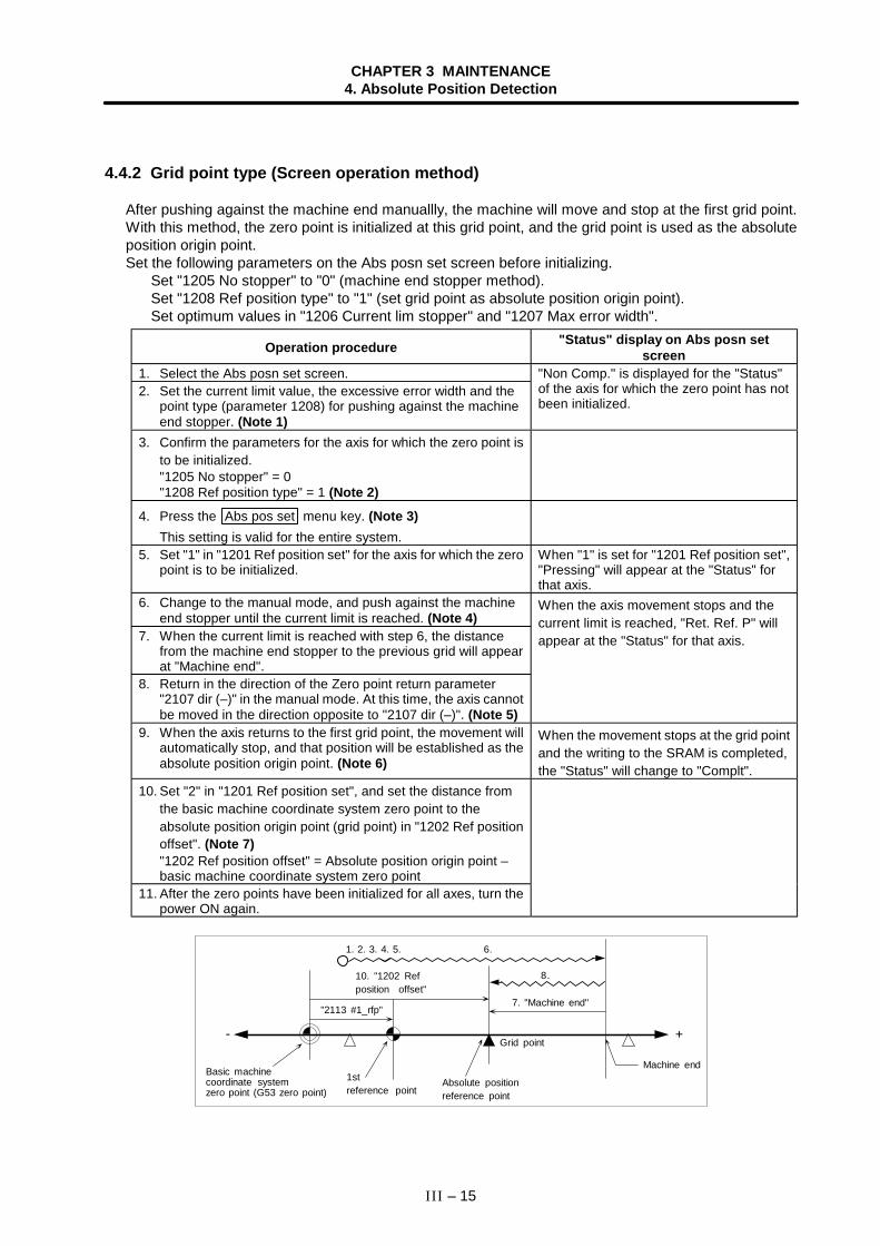
CHAPTER 3 MAINTENANCE4. Absolute Position Detection
III – 15
4.4.2 Grid point type (Screen operation method)
After pushing against the machine end manuallly, the machine will move and stop at the first grid point.With this method, the zero point is initialized at this grid point, and the grid point is used as the absoluteposition origin point.Set the following parameters on the Abs posn set screen before initializing.
Set "1205 No stopper" to "0" (machine end stopper method).Set "1208 Ref position type" to "1" (set grid point as absolute position origin point).Set optimum values in "1206 Current lim stopper" and "1207 Max error width".
Operation procedure "Status" display on Abs posn setscreen
1. Select the Abs posn set screen.2. Set the current limit value, the excessive error width and the
point type (parameter 1208) for pushing against the machineend stopper. (Note 1)
"Non Comp." is displayed for the "Status"of the axis for which the zero point has notbeen initialized.
3. Confirm the parameters for the axis for which the zero point isto be initialized."1205 No stopper" = 0"1208 Ref position type" = 1 (Note 2)
4. Press the Abs pos set menu key. (Note 3)This setting is valid for the entire system.
5. Set "1" in "1201 Ref position set" for the axis for which the zeropoint is to be initialized.
When "1" is set for "1201 Ref position set","Pressing" will appear at the "Status" forthat axis.
6. Change to the manual mode, and push against the machineend stopper until the current limit is reached. (Note 4)
7. When the current limit is reached with step 6, the distancefrom the machine end stopper to the previous grid will appearat "Machine end".
8. Return in the direction of the Zero point return parameter"2107 dir (–)" in the manual mode. At this time, the axis cannotbe moved in the direction opposite to "2107 dir (–)". (Note 5)
When the axis movement stops and thecurrent limit is reached, "Ret. Ref. P" willappear at the "Status" for that axis.
9. When the axis returns to the first grid point, the movement willautomatically stop, and that position will be established as theabsolute position origin point. (Note 6)
When the movement stops at the grid pointand the writing to the SRAM is completed,the "Status" will change to "Complt".
10. Set "2" in "1201 Ref position set", and set the distance fromthe basic machine coordinate system zero point to theabsolute position origin point (grid point) in "1202 Ref positionoffset". (Note 7)"1202 Ref position offset" = Absolute position origin point –basic machine coordinate system zero point
11. After the zero points have been initialized for all axes, turn thepower ON again.
+-
1. 2. 3. 4. 5. 6.
"2113 #1_rfp"
8.
Basic machinecoordinate systemzero point (G53 zero point)
10. "1202 Refposition offset"
1streference point
Absolute positionreference point
Machine end
Grid point
7. "Machine end"
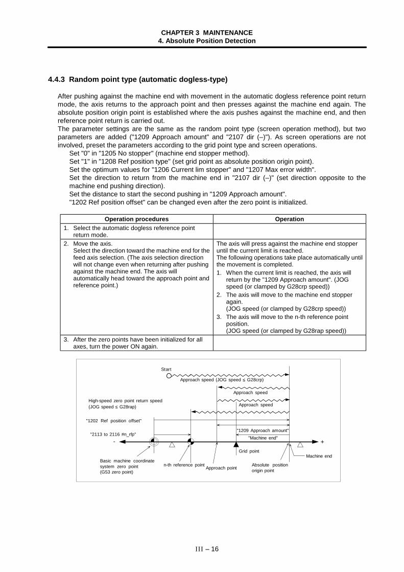
CHAPTER 3 MAINTENANCE4. Absolute Position Detection
III – 16
4.4.3 Random point type (automatic dogless-type)
After pushing against the machine end with movement in the automatic dogless reference point returnmode, the axis returns to the approach point and then presses against the machine end again. Theabsolute position origin point is established where the axis pushes against the machine end, and thenreference point return is carried out.The parameter settings are the same as the random point type (screen operation method), but twoparameters are added ("1209 Approach amount" and "2107 dir (–)"). As screen operations are notinvolved, preset the parameters according to the grid point type and screen operations.
Set "0" in "1205 No stopper" (machine end stopper method).Set "1" in "1208 Ref position type" (set grid point as absolute position origin point).Set the optimum values for "1206 Current lim stopper" and "1207 Max error width".Set the direction to return from the machine end in "2107 dir (–)" (set direction opposite to themachine end pushing direction).Set the distance to start the second pushing in "1209 Approach amount"."1202 Ref position offset" can be changed even after the zero point is initialized.
Operation procedures Operation1. Select the automatic dogless reference point
return mode.2. Move the axis.
Select the direction toward the machine end for thefeed axis selection. (The axis selection directionwill not change even when returning after pushingagainst the machine end. The axis willautomatically head toward the approach point andreference point.)
The axis will press against the machine end stopperuntil the current limit is reached.The following operations take place automatically untilthe movement is completed.1. When the current limit is reached, the axis will
return by the "1209 Approach amount". (JOGspeed (or clamped by G28crp speed))
2. The axis will move to the machine end stopperagain.(JOG speed (or clamped by G28crp speed))
3. The axis will move to the n-th reference pointposition.(JOG speed (or clamped by G28rap speed))
3. After the zero points have been initialized for allaxes, turn the power ON again.
"1202 Ref position offset"
Basic machine coordinatesystem zero point(G53 zero point)
+-
Machine end Grid point
n-th reference point
"2113 to 2116 #n_rfp"
Absolute positionorigin point
"Machine end"
Start
"1209 Approach amount"
Approach speed (JOG speed ≤ G28crp)
Approach speed
Approach speedHigh-speed zero point return speed(JOG speed ≤ G28rap)
Approach point
CHAPTER 3 MAINTENANCE4. Absolute Position Detection
III – 17
4.4.4 Grid point type (automatic dogless-type)
After pushing against the machine end in the automatic dogless reference point return mode, the axisreturns to the approach point and then presses against the machine end again. The absolute position isestablished at the first gird point after the machine end is pressed. After that, reference point return iscarried out.The parameter settings are the same as the grid point type (screen operation method), but oneparameter is added ("1209 Approach amount"). As screen operations are not involved, preset theparameters according to the grid point type and screen operations.
Set "0" in "1205 No stopper" (machine end stopper method).Set "1" in "1208 Ref position type" (set grid point as absolute position origin point).Set the optimum values for "1206 Current lim stopper" and "1207 Max error width".Set the direction to return from the machine end in "2107 dir (–)" (set direction opposite to themachine end pushing direction).Set the distance to start the second pushing in "1209 Approach amount"."1202 Ref position offset" can be changed even after the zero point is inititalized.
Operation procedures Operation1. Select the automatic dogless reference point
return mode.2. Move the axis.
Select the direction toward the machine end for thefeed axis selection. (The axis selection directionwill not change even when returning after pushingagainst the machine end. The axis willautomatically head toward the approach point andreference point.)
The axis will press against the machine end stopperuntil the current limit is reached.The following operations take place automatically untilthe movement is completed.1. When the current limit is reached, the axis will
return by the "1209 Approach amount". (The speedless than JOG speed and G28crp speed)
2. The axis will move to the machine end stopperagain.(JOG speed (or clamped by G28crp speed))
3. The axis will return to the previous grid.(Jog speed (or clamped by G28crp speed))
4. The axis will move to the n-th reference pointposition.(JOG speed (or clamped by G28rap speed))
3. After the zero points have been initialized for allaxes, turn the power ON again.
+-
"1202 Ref position offset"
Basic machine coordinatesystem zero point(G53 zero point)
Machine end Grid point
n-th reference point
"2113 to 2116 #n_rfp"
Absolute positionorigin point
"Machine end"
Start
"1209 Approach amount"
Approach speed (JOG speed ≤ G28crp)
Approach speed
Approach speedHigh-speed zero point return speed(JOG speed ≤ G28rap)
Approach point
Approach speed
CHAPTER 3 MAINTENANCE4. Absolute Position Detection
III – 18
4.4.5 Notes
(Note 1) to (Note 7) in sections 4.4.1 and 4.4.2 correspond to the following items.
1) The current limit value (%) can be set with Servo parameter "2114 SV014". The excessive error widthcan be set with Servo parameter "2253 SV053".
2) If "1205 No stopper" on the Abs posn set screen is set to "1", set it to "0" before setting "1201 Refposition set".
3) The Abs pos set menu key on the Abs posn set screen cannot be turned OFF from the screen. Thismenu will turn OFF when the power is turned ON again. Automatic operation and zero point returncannot be carried out while this menu is ON. (An error will occur.)
4) Before the zero point initialization is carried out, the Z-phase grid point must be passed once after thepower is turned ON. If the grid point has not been passed even once after the power was turned ON,the error "Some ax does not pass Z phase" will occur when the current limit is reached. In this case,return the axis by one grid or more, and repeat the operations from step 6.
5) When using the grid point type (screen operation method) or automatic dogless-type, set thedirection to return from the machine end (opposite direction from machine end stopper direction) in"2107 dir(–)".
6) When using the grid point type, the grid mask amount can be set in the Zero point return parameter"2105 grmask". If the grid mask amount is larger than the distance from the machine end stopper to thegrid point, the next grid point will be used as the absolute position origin point.
10."1202 Ref position offset"
Basic machinecoordinate systemzero point (G53 zero point)
+
Machineend
1. 2. 3. 4. 5.
Grid point
1streference point
"2113 #1_rfp"
Absolute positionorigin point
7. "Machine end"
8.
2105grmask
6.
-
7) When the dogless-type absolute position detection is carried out, the reference point shiftamount (Zero point return parameter "2103 G28sft") will be invalid.
CHAPTER 3 MAINTENANCE4. Absolute Position Detection
III – 19
4.5 Procedures for the dogless-type detection; initializing with marked pointalignment method
The absolute position is established by making a mark at a random point within the machine's moveablerange, and moving manually to the marked position.The marked point alignment method includes the type that uses a random marked point as the absoluteposition origin point, and the type that uses the grid point near the marked point as the absolute positionorigin point.(The grid point is the hypothetical grid determined by the Zero point return parameter "2104 grspc"setting.)
4.5.1 Random point type (Screen operation method)With this method, the machine is moved to the marked point manually to initialize the zero point, andusing the marked point as the absolute position origin point.Set the following parameters on the Abs posn set screen before initializing.
Set "1205 No stopper" to "1" (marked point alignment method).Set "1208 Ref position type" to "0" (set mark point as absolute position origin point).
Operation procedure "Status" display on Abs posn setscreen
1. Select the Abs posn set screen. "Non Comp." is displayed for the "Status"of the axis for which the zero point has notbeen initialized.
2. Confirm the parameters for the axis for which the zero point isto be initialized."1205 No stopper" = 1"1208 Ref position type" = 0 (Note 1)
3. Press the Abs pos set menu key. (Note 2)This setting is valid for the entire system.
4. Change to the manual mode, and move to the marked point.(Note 3)
5. Set "1" in "1201 Ref position set" for the axis for which the zeropoint is to be initialized.
6. Set "2" in "1201 Ref position set", and set the distance fromthe basic machine coordinate system zero point to theabsolute position origin point (marked point) in "1202 Refposition offset". (Note 5)"1202 Ref position offset" = Absolute position origin point –basic machine coordinate system zero point
7. After the zero points have been initialized for all axes, turn thepower ON again.
When the axis movement stops and "1" isset for "1201 Ref position set", "Ret. Ref.P" will appear at the "Status" for that axis.When writing to the SRAM is completed,"Complt" will appear.
+-
1. 2. 3.
"2113 #1_rfp"
5.4.
6. "1202 Ref position offset"
Basic machinecoordinate systemzero point (G53 zero point)
1st reference pointAbsolute positionorigin point
Markedpoint
Grid point
CHAPTER 3 MAINTENANCE4. Absolute Position Detection
III – 20
4.5.2 Grid point type (Screen operation method)
After manually moving to the marked point, the machine will move and stop at the first grid point. Theabsolute position origin point is established at this grid point, and the grid point is used as the absoluteposition origin point.Set the following parameters on the Abs posn set screen before initializing.
Set "1205 No stopper" to "1" (marked point alignment method).Set "1208 Ref position type" to "1" (set grid point as absolute position origin point).
Operation procedure "Status" display on Abs posn setscreen
1. Select the Abs posn set screen. "Non Comp." is displayed for the "Status"of the axis for which the zero point has notbeen initialized.
2. Confirm the parameters for the axis for which the zero point isto be initialized."1205 No stopper" = 1"1208 Ref position type" = 1 (Note 1)
3. Press the Abs pos set menu key. (Note 2)This setting is valid for the entire system.
4. Change to the manual mode, and move to the marked point.5. Set "1" in "1201 Ref position set" for the axis for which the zero
point is to be initialized. (Note 3)6. The distance from the machine reference position to the
previous grid will appear at "Machine end".7. Return in the direction of the Zero point return parameter
"2107 dir (–)" in the manual mode. At this time, the axis cannotbe moved in the direction opposite to "2107 dir (–)". (Note 4)
When the axis movement stops and "1" isset for "1201 Ref position set", "Ret. Ref.P" will appear at the "Status" for that axis.
8. When reaches to the first grid point, the movement willautomatically stop, and that position will be established as theabsolute position origin point. (Note 5)
9. Set "2" in "1201 Ref position set", and set the distance fromthe basic machine coordinate system zero point to theabsolute position origin point (grid point) in "1202 Ref positionoffset". (Note 5)"1202 Ref position offset" = Absolute position origin point –basic machine coordinate system zero point
10. After the zero points have been initialized for all axes, turn thepower ON again.
When the machine stops at the grid pointand writing to the SRAM is completed,"Complt" will appear at "Status".
+-
1. 2. 3.
"2113 #1_rfp"
7.
5.4.
9."1202 Ref position offset"
Basic machinecoordinate systemzero point (G53 zero point)
1streference point
Absolute positionorigin point
Marked point
Grid point
6. "Machine end"
CHAPTER 3 MAINTENANCE4. Absolute Position Detection
III – 21
4.5.3 Notes
(Note 1) to (Note 5) in sections 4.5.1 and 4.5.2 correspond to the following items.
1) If "1205 No stopper" on the Abs posn set screen is set to "0", set it to "1" before setting "1201 Refposition set".
2) The Abs pos set menu key on the Abs posn set screen cannot be turned OFF from the screen. Thismenu will turn OFF when the power is turned ON again. Automatic operation and zero point returncannot be carried out while this menu is ON. (An error will occur.)
3) Before the zero point initialization is carried out, the Z-phase grid point must be passed once after thepower is turned ON. If the grid point has not been passed even once after the power was turned ON,"1" cannot be set in "1201 Ref position set". (An error will occur.) In this case, return the axis by onegrid or more, and repeat the operations from step 4.
4) When using the grid point type (screen operation method), set the direction to return from the markpoint (0: positive direction, 1: negative direction) in "2107 dir(–)".
5) When using the grid point type, the grid mask amount can be set in the Zero point return parameter"2105 grmask". If the grid mask amount is larger than the distance from the marked point to the gridpoint, the next grid point will be used as the absolute position origin point.
+-
1. 2. 3. 4. 5.
"2113 #1_rfp"
7.
2105grmask
6.
7. "1202 Ref position offset"
6. "Machine end"
Basic machinecoordinate systemzero point(G53 zero point)
1st reference point
Grid point
Absolute positionreference point
Markedpoint
6) When the dogless-type absolute position detection is carried out, the reference point shift amount (Zeroreturn parameter "2103 G28sft") will be invalid.
CHAPTER 3 MAINTENANCE4. Absolute Position Detection
III – 22
4.6 Various settings for dogless-type absolute position detection
(1) Resetting the basic machine coordinate systemAfter the zero point is initialized, the basic machine coordinate system can be reset by changing the"1202 Ref position offset" parameter.
Operation procedure "Status" display on Abs posn setscreen
1. Select the Abs posn set screen.
2. Press the Abs pos set menu key.
3. Change to the manual mode, and designate the axis for whichthe basic machine coordinate system is to be reset. Set "2" for"1201 Ref position set" of that axis.
4. Reset the distance from the basic machine coordinatesystem zero point to the absolute position origin point in"1202 Ref position offset".
5. Turn the power ON again.
Confirm that the zero point has beeninitialized for the axis. ("Non Comp" isdisplayed at "Status".)"2" can be set in "1201 Ref position set" ifthe zero point has been initialized for theaxis.
<Random point type when "1208 Ref position type" = 0>
+-
"#1_rfp"
"#1_rfp"
New "1202 Ref position offset"
Old "1202 Ref position offset"
New basic machinecoordinate systemzero point (G53 zero point)
New 1streference point
Old basic machinecoordinate systemzero point (G53 zero point)
Old 1st reference point Absolute positionorigin point
Machine endor referencemark point
<Grid point type when "1208 Ref position type" = 1>
"#1_rfp"
"#1_rfp"
+-
New "1202 Ref position offset"
Old "1202 Refposition offset"
New basic machinecoordinate systemzero point (G53 zero point)
New 1streference point Old basic machine
coordinate systemzero point (G53 zero point)
Old 1st reference pointAbsolute positionorigin point
Machine endor referencemark point
(Note 1) Make sure that the basic machine coordinate system zero point (G53 zero point) is not outsideof the machine end stopper.
CHAPTER 3 MAINTENANCE4. Absolute Position Detection
III – 23
(2) Setting the reference point (G28 zero point)By setting "2113 #1_rfp", the 1st reference point can be created in the following manner.
<Random point type when "1208 Ref position type" = 0>
+-
Old "2113 #1_rfp"
New "2113 #1_rfp"
"1202 Ref position offset"
New basic machinecoordinate systemzero point (G53 zero point)
Old 1streference point
New 1st reference pointAbsolute positionorigin point
Machine endor referencemark point
<Grid point type when "1208 Ref position type" = 1>
New "2113 #1_rfp"
Old "2113 #1_rfp"
+-
"1202 Ref position offset"
New basic machinecoordinate systemzero point (G53 zero point)
Old 1streference point
New 1st reference pointAbsolute positionorigin point
Machine endor referencemark point
(Note 1) Make sure that the reference return point (G28 zero point) is not outside of the machine endstopper.
CHAPTER 3 MAINTENANCE4. Absolute Position Detection
III – 24
4.7 Absolute position detection check function
To ensure reliability, various checks are made during the absolute position detection.
(1) Absolute position coordinate check at power ONThe following steps are carried out to obtain information for diagnosing absolute position errors inthe absolute position detection system.(a) The machine position when the power is turned OFF and the machine position when the power
is turned ON are displayed on the Amp monitor screen.(b) If the difference of the machine positions when the power is turned OFF and ON exceeds the
tolerable value (Abs posn set screen "1203 Move amnt in pwr OFF"), an absolute positionwarning will turn ON and will be output to the user PLC. The absolute position warning outputcan be reset with the reset signal or by pressing the reset button on the operation panel.
(Note) If the "1203 Move amnt in pwr OFF" value is "0", the following value will be used as thetolerable value.
Tolerable value = 0.9 ∗ PIT (ball screw pitch) ∗ 100 [µm]
(2) Initialization data check at power ONIf errors are detected in the following data when the power is turned ON (if the data differs from thatsaved during initialization), an error will be output.(a) Absolute position origin point (Amp monitor screen "R0", "P0")(b) Absolute position origin point machine coordinate value (Abs posn set screen "1202 Ref
position offset") (Only during dogless-type absolute position detection)
(3) Parameter check at power ONIf errors are detected in the following parameters when the power is turned ON (if the data differsfrom that saved during initialization), an error will be output.
Basic commonparameter
1305 M_inch∗
Basic axis parameter 100510061007
iout∗rot∗ *ccw∗
Servo parameter 22012202221822192225
PC1PC2PITRNG1MTYP
CHAPTER 3 MAINTENANCE5. Daily Maintenance
III – 25
5. Daily Maintenance
5.1 Daily inspection
5.1.1 Checking the external view
(1) Machine oil (cutting oil, lubrication oil) have been scattered onto the servomotor, detector, or controlunit of the NC, or is leaking.
(2) Damage is found on the cables of the movable blocks, or the cables are twisted.(3) Filter clogging(4) A door of the control panel is not open.(5) Ambient vibration(6) The unit is located in a dusty location.(7) Something that causes high frequency is placed near the NC unit.
5.1.2 Checking the inside of the control panel
(1) Cable connectors are loosened.(2) Installing screws are loosened.(3) Attachment amplifier screws are loosened.(4) The cooling fan operates abnormally.(5) Cable damage(6) PCB have been inserted abnormally.
CHAPTER 3 MAINTENANCE5. Daily Maintenance
III – 26
5.2 Replacement
5.2.1 Replacing the battery
Data such as parameters and machining programs that must be backed up when the power is OFF issaved by a lithium battery installed in the control section battery holder.
Battery ...................................................... ER6 with connector (Toshiba, with Mitsubishi Electricspecifications)
Initial battery voltage................................. 3.6VLow battery voltage detection voltage ...... 2.8V (Battery voltage drop caution alarm)
2.6V (Battery voltage drop warning alarm)Total time data is saved by the battery .... 45,000 hours (At room temperature. Total time will be
shorter at high temperatures.)Battery life................................................. Approx. 5 years. (From the date of manufacture.)Discharge current ..................................... 40µA or less
(Replace the battery immediately if a Battery voltage drop caution alarm appears. The internal data maybe destroyed if the Battery voltage drop warning alarm appears.)
(1) Replacement procedureTurn the control section power OFF when replacing the battery.Complete the battery replacement within 30 minutes of turning the power OFF. (If a battery is notconnected within 30 minutes of turning the power OFF, the data backed up by the battery may bedestroyed.)1) Confirm that the control section power is OFF. (If the power is not OFF, turn it OFF.)2) Open the operation box door, and open the front cover to the control section.3) Remove the battery from the battery holder.4) Pull the connector connected to the battery out from the BAT connector on the control section
HR081 PCB.5) Replace the battery with the new one. Insert the connector connected to the new battery into the
BAT connector on the control section HR081 PCB.6) Fit the battery into the battery holder.7) Close the front cover of the control section, and close the operation box door.
HR081BAT connector
ConnectorBattery holder
BatteryFront cover
Open the front coverof the control section.
Control section
CHAPTER 3 MAINTENANCE5. Daily Maintenance
III – 27
(2) Battery handling notes• Always replace the battery with the same type battery.• Do not disassemble the battery.• Do not incinerate the battery or immerse it in water.• Do not deform the battery by pressurizing.• This is a disposable battery. Do not recharge.• Dispose of the spent battery as the industrial waste.
CAUTIONIf the BATTERY LOW warning is output, save the machining programs, tool data and parametersto an I/O device, and then replace the battery. If the BATTERY alarm occurs, the machiningprograms, tool data and parameters may be damaged. After replacing the battery, reload eachdata item.Do not replace the battery while the power is ON.Do not short-circuit, charge, overheat, incinerate or disassemble the battery.Dispose of the spent battery according to local laws.
CHAPTER 3 MAINTENANCE5. Daily Maintenance
III – 28
5.2.2 Replacing the backlights
A cold-cathode tube is used as a light source (backlight) in the LCD panel.The life of the backlight is 10,000 h/25°C (Time to when the luminance drops to 50% of the initial value.)The backlight life is dependent on the temperature. The life tends to be shorter when used continuouslyat lower temperatures.
LCD panel........... KCS6448HSTT-X3 (Kyocera)Backlight ............. KCI-04 (Kyocera)Backlight life ....... 10,000 h/25°C (Time to when the luminance drops to 50% of the initial value.)
(1) Replacement procedureTurn the control section power OFF when replacing the LCD panel backlight.1) Confirm that the control section power is OFF. (If the power is not OFF, turn it OFF.)2) Open the operation box door.3) Pull the connectors connected to the backlights out from the backlight power PCB. (Two
locations, top and bottom.)4) Remove the fixing screws (two locations, top and bottom left) of the control section installation
fitting, and open the control section installation fitting.5) Pull out the backlights built into the top and bottom left of the LCD panel. (The backlights have
locking claws on the front. Hold these claws down while pulling the backlight out.)6) Insert the two new backlights into the top and bottom left of the LCD panel. (Press in until the
locking claws click.)7) Close the control section installation fitting, and fix it with the fixing screws. (Two locations, top
and bottom left.)8) Connect the backlight connectors to the backlight power PCB.9) Close the operation box door.
LCD display section (back)
Pull out
Press in Backlight
Open
Fixing screw
Connector
Control section installation fitting
LCD panelBacklightpower PCB
Control section
Pull out
Press in
BacklightFixing screw
Connector
CAUTIONDo not replace the backlight while the power is ON.Dispose of the spent backlights according to local laws.
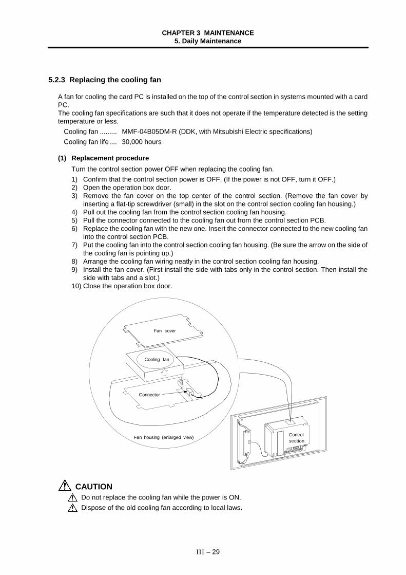
CHAPTER 3 MAINTENANCE5. Daily Maintenance
III – 29
5.2.3 Replacing the cooling fan
A fan for cooling the card PC is installed on the top of the control section in systems mounted with a cardPC.The cooling fan specifications are such that it does not operate if the temperature detected is the settingtemperature or less.
Cooling fan ......... MMF-04B05DM-R (DDK, with Mitsubishi Electric specifications)Cooling fan life.... 30,000 hours
(1) Replacement procedureTurn the control section power OFF when replacing the cooling fan.1) Confirm that the control section power is OFF. (If the power is not OFF, turn it OFF.)2) Open the operation box door.3) Remove the fan cover on the top center of the control section. (Remove the fan cover by
inserting a flat-tip screwdriver (small) in the slot on the control section cooling fan housing.)4) Pull out the cooling fan from the control section cooling fan housing.5) Pull the connector connected to the cooling fan out from the control section PCB.6) Replace the cooling fan with the new one. Insert the connector connected to the new cooling fan
into the control section PCB.7) Put the cooling fan into the control section cooling fan housing. (Be sure the arrow on the side of
the cooling fan is pointing up.)8) Arrange the cooling fan wiring neatly in the control section cooling fan housing.9) Install the fan cover. (First install the side with tabs only in the control section. Then install the
side with tabs and a slot.)10) Close the operation box door.
Fan cover
Cooling fan
Connector
Fan housing (enlarged view) Controlsection
CAUTIONDo not replace the cooling fan while the power is ON.Dispose of the old cooling fan according to local laws.
CHAPTER 3 MAINTENANCE5. Daily Maintenance
III – 30
5.2.4 Replacing the hard disk drive (HDD)
Depending on the hardware specifications, the hard disk drive is either built into the control section orinstalled externally to the control section. In either case, it is connected to the control section HR121 PCBby an F140 cable.
HDD.................... MK1924FCV (Toshiba)HDD life .............. 5 years or 20,000 hours of power ON, whichever comes first.HDD unit ............. FCU6-HD101-1 (Mitsubishi Electric)
(1) Replacement procedure
< HDD built into the control section >Turn the control section power OFF when replacing the HDD.1) Confirm that the control section power is OFF. (If the power is not OFF, turn it OFF.)2) Open the operation box door, and open the front cover to the control section.3) Remove the PCMCIA interface HR841 PCB in the control section if one is built-in.4) Disconnect the F140 cable connected to the control section HR121 PCB side.5) Remove the fixing screws on the HDD fixing bracket, and remove the HDD fixing bracket.6) Holding the center right side of the HDD installation fitting, remove the HDD and installation
fitting together.7) Remove the HDD from the installation fitting.
(Pull the HDD toward the top of the installation fitting and remove the damping cushions.)8) Disconnect the F140 cable from the HDD, and connect it to the new HDD.
(Pay attention to the connector direction when installing.)9) Install the HDD onto the HDD installation fitting with the HDD PCB section up.
(Install the HDD in the grooves of the damping cushions attached to the HDD installation fitting.)10) Install the damping cushions between the tops of the HDD and HDD installation fitting.
(Install the damping cushions so they fit snugly in the positioning holes on the side of the HDDinstallation fitting.)
11) Install the HDD installation fitting onto the control section.12) Install the HDD fixing bracket, and fix with the fixing screws.
(Install the HDD fixing bracket by inserting it between the HDD installation fitting and the clawson the left side of the control section case.)
13) Connect the F140 cable attached to the HDD to the control section HR121 PCB.14) Install the PCMCIA interface HR841 PCB in the control section if one is built-in.15) Close the front cover to the control section, and close the operation box door.
(Note) Refer to the Maintenance and Connection Manual for information on removal/installation ofthe PCMCIA interface HR841 PCB.
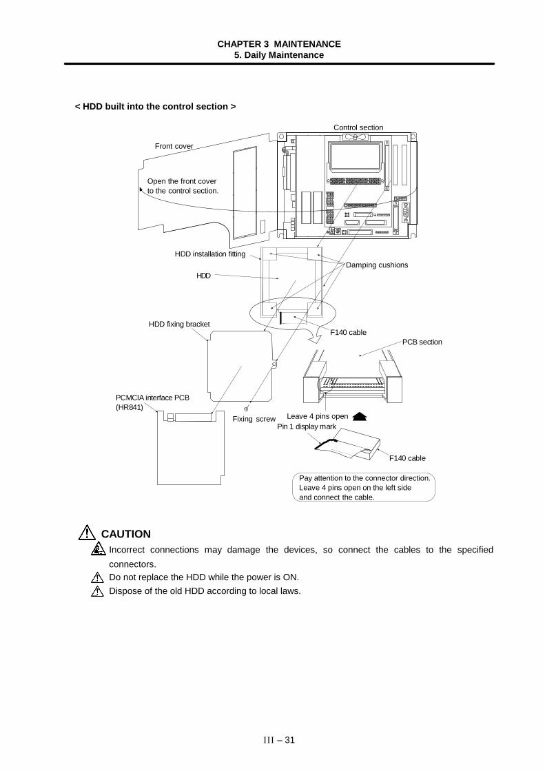
CHAPTER 3 MAINTENANCE5. Daily Maintenance
III – 31
< HDD built into the control section >
HDD
Pay attention to the connector direction.Leave 4 pins open on the left sideand connect the cable.
Front cover
Open the front coverto the control section.
Control section
HDD installation fittingDamping cushions
HDD fixing bracketF140 cable
F140 cable
PCB section
PCMCIA interface PCB(HR841)
Fixing screwPin 1 display mark
Leave 4 pins open
CAUTIONIncorrect connections may damage the devices, so connect the cables to the specifiedconnectors.Do not replace the HDD while the power is ON.Dispose of the old HDD according to local laws.
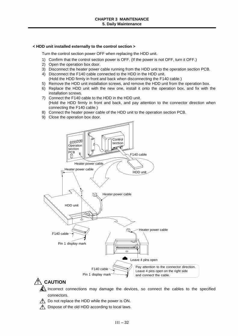
CHAPTER 3 MAINTENANCE5. Daily Maintenance
III – 32
< HDD unit installed externally to the control section >
Turn the control section power OFF when replacing the HDD unit.1) Confirm that the control section power is OFF. (If the power is not OFF, turn it OFF.)2) Open the operation box door.3) Disconnect the heater power cable running from the HDD unit to the operation section PCB.4) Disconnect the F140 cable connected to the HDD in the HDD unit.
(Hold the HDD firmly in front and back when disconnecting the F140 cable.)5) Remove the HDD unit installation screws, and remove the HDD unit from the operation box.6) Replace the HDD unit with the new one, install it onto the operation box, and fix with the
installation screws.7) Connect the F140 cable to the HDD in the HDD unit.
(Hold the HDD firmly in front and back, and pay attention to the connector direction whenconnecting the F140 cable.)
8) Connect the heater power cable of the HDD unit to the operation section PCB.9) Close the operation box door.
OperationsectionPCB
Heater power cable
HDD unit
Pay attention to the connector direction.Leave 4 pins open on the right sideand connect the cable.
F140 cable
F140 cable
Pin 1 display mark
Leave 4 pins open
F140 cablePin 1 display mark
Heater power cable
HDD unit
Heater power cable
Controlsection
Heater power cable
CAUTIONIncorrect connections may damage the devices, so connect the cables to the specifiedconnectors.Do not replace the HDD while the power is ON.Dispose of the old HDD according to local laws.
CHAPTER 3 MAINTENANCE5. Daily Maintenance
III – 33
5.3 Cleaning and handling
5.3.1 Escutcheon
(1) Cleaning the escutcheonWipe the escutcheon with a soft, clean, dry cloth. If cleaning is still required, put some neutraldetergent on a cloth and wipe. Do not use alcohol, thinner, etc.
5.3.2 Floppy disk
(1) Cleaning the floppy disk unitAfter using the floppy disk unit for long periods, magnetic powder from disk, dust and dirt will adhereon the head surface. This may cause faulty reading and writing.Periodically (about once every two months) clean the head of the floppy disk unit using the followingprocedure.
(a) Recommended cleaning diskMaker : Memorex JapanType : Memorex Cleaning Floppy 3.5-inch double-sidedMethod : Dry method
(b) Cleaning method 1) Insert the cleaning disk into the floppy disk unit to be cleaned. 2) Start the cleaning program, and operate following the instructions on the screen. 3) When the program is finished, eject the cleaning disk. (Note) The cleaning disk has a limited No. of uses.
• Replace a cleaning disk that has exceeded its maximum No. of uses with a new one. • Read the cleaning disk instruction manual to find out the maximum No. of uses.
CHAPTER 3 MAINTENANCE5. Daily Maintenance
III – 34
(2) Handling floppy disksPlease observe the following points to ensure long use of floppy disks.
(a) Notes for use
1) Never touch the magnetic surface of the floppy disk.The disk may become impossible to read if fingerprints adhere to themagnetic surface.
2) Do not touch the disk with oil or iron filings on the hands.
3) Keep the floppy disk away from cigarette smoke, etc. Do not allowany solvent to contact the magnetic surface.
4) When attaching an index label on the floppy disk, attach the label inthe correct positions so it will not peel off. Do not attach more thanone label on the floppy disk.
5) Write on the index label before attaching it to the floppy disk. Use asoft-tipped instrument such as a felt-tip pen to write on labels alreadyattached to the floppy disk.
6) Gently insert the floppy disk into the floppy disk unit with the correctorientation. The floppy disk may be damaged if it is roughly insertedor removed.
7) Before using a floppy disk brought in from outdoors where there is agreat difference in temperature or humidity, leave the disk in theroom for at least 30 minutes.
(b) Notes for storage
1) Always store floppy disks that are not being used and backup floppydisks in a plastic case.
2) Do not leave floppy disks in direct sunlight or near heaters.
3) Keep floppy disks away from magnets or objects having a strongmagnetic field.Magnetic rings, necklaces, etc., can also cause damage to the floppydisk data, so avoid wearing these when handling floppy disks.
4) Do not place heavy objects on floppy disks.
CHAPTER 3 MAINTENANCE5. Daily Maintenance
III – 35
(3) Other notes for use(a) Life of the floppy disk unit
The durability of the floppy disk unit is guaranteed for five years of FDD motor operation or12,000 hr of accessing, whichever comes first. However, correct reading/writing may becomeimpossible sooner if dust and foreign matter adhere to the drive under a dusty, dirty, etc.,working environment.Periodically clean the floppy disk unit head (refer to section 5.3.2 (1)) to avoid trouble such asthis.
(b) Backup recommendationFloppy disks should be copied when suitable, as a precaution against floppy disk damage, datadamage, etc., as well as for storing important data.
(c) Observance of working conditionsFloppy disk units and floppy disks are sensitive to temperature and humidity changes, dust anddirt. Therefore, floppy disk units and floppy disks should be used observing the notes mentionedabove.If the working conditions are not satisfied, especially with regard to temperature, (for example,when starting at temperatures below freezing) the data track and head position may deviate,making correct reading impossible.In this case wait for the inside temperature to rise before starting.
(d) Writing to floppy disksThe correct temperature range for writing to floppy disks is between 10°C to 40°C.Observe the temperature conditions when writing to floppy disks.
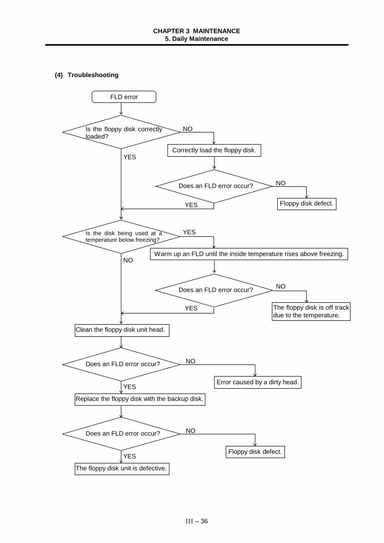
CHAPTER 3 MAINTENANCE5. Daily Maintenance
III – 36
(4) Troubleshooting
FLD error
Is the floppy disk correctlyloaded?
Does an FLD error occur?
Correctly load the floppy disk.
Is the disk being used at atemperature below freezing?
Floppy disk defect.
Does an FLD error occur?
Warm up an FLD until the inside temperature rises above freezing.
The floppy disk is off trackdue to the temperature.
Clean the floppy disk unit head.
Does an FLD error occur?
Replace the floppy disk with the backup disk.
Error caused by a dirty head.
Does an FLD error occur?
The floppy disk unit is defective.
Floppy disk defect.
NO
NO
YES
YES
YES
NO
NO
YES
NO
YES
NO
YES
CHAPTER 3 MAINTENANCE5. Daily Maintenance
III – 37
5.3.3 Hard disk drive
(1) Handling the hard disk
(a) Notes for use1) Correctly connect the cable.2) Do not touch the connector area with the hands or metal.3) Do not apply excessive force to the connector area.4) Do not subject the hard disk to dropping or strong impacts.5) Do not disassemble the hard disk.
(b) Notes for storage1) Do not store the hard disk in locations having a high temperature or humidity.2) Keep the hard disk away from magnets or objects having a strong magnetic field.
(2) Other notes for use
(a) Backup recommendationHard disks have a limited life, and so should be copied when suitable as a note as well as forstoring important data.
5.3.4 LCD panel
(1) Handling the LCD panel
(a) Notes for use1) The polarizing plate (display surface) of the LCD panel surface can be easily scratched, so
be careful during handling.2) Glass is used in the LCD panel. Be careful not to drop the LCD panel or allow it to hit hard
objects, as the glass may chip or break.3) The polarizing plate may be stained or discolored if drops of water, etc., adhere to it for long
periods, so be sure to wipe off any moisture immediately.4) Wipe off any dirt, dust, etc., on the polarizing plate using absorbent cotton or other soft cloth.5) A CMOS LSI is used in the LCD panel, so be careful of static electricity when handling.6) Never disassemble the LCD panel. Doing so will damage the panel.
(b) Notes for storage1) Do not store the LCD panel in locations having a high temperature or humidity. (Store within
the storage temperature range.)2) When storing the LCD panel as an individual unit, be sure that other objects do not touch or
hit the polarizing plate (display surface).3) When storing the LCD panel for extended periods, be sure to store in a dark place away from
exposure to direct sunlight or fluorescent light.
CHAPTER 3 MAINTENANCE5. Daily Maintenance
III – 38
(2) Other notes for use
(a) Backlight lifeThe life of the backlight is 10,000 h/25°C.(Time to when the luminance drops to 50% of the initial value.)The backlight life is dependent on the temperature. The life tends to be shorter when usedcontinuously at lower temperatures.
(b) Luminance startAs a characteristic of the backlight, the luminance may drop slightly at lower temperatures. Ittakes 10 to 15 minutes for the luminance to reach the rated value after the power is turned ON.
(c) Unevenness, luminescent spots and defectsUneven brightness, small luminescent spots or small dark spots may appear on LCD, but this isnot a fault.
(d) ContrastThe contrast of STN method LCD panels changes with temperature fluctuation. If this happensand the panel is difficult to see, open the operation box door and adjust the contrast with thecontrast adjustment volume on the LCD signal interface PCB.
5.3.5 PCMCIA Card
(1) Handling the PCMCIA cardThe general handling methods for the PCMCIA Card are described below.Refer to the instruction manual of the PCMCIA Card used for details.(a) Notes for use
1) Insert the card in the correct direction.2) Do not touch the connector area with the hands or metal.3) Do not apply excessive force to the connector area.4) Do not subject the card to bending or strong impacts.5) Do not open the cover or disassemble the card.6) Do not use the card in dusty locations.
(b) Notes for storage1) Do not store the card in locations having a high temperature or humidity.2) Do not store the card in dusty locations.
CHAPTER 3 MAINTENANCE8. Fault Diagnosis and Action
III – 39
6. Fault Diagnosis and Action
6.1 Checking the fault occurrence status
Check the following:• When did the fault occur?• During what operation did the fault occur?• What fault?
(1) When did the fault occur?Time of day when the fault occurred.
(2) During what operation did the fault occur?What NC operation mode?
• For automatic operation ...... Program number, sequence number, and contents of program• For manual operation .......... Mode?
Operating procedure?Preceding and succeeding operations?
• Setting display unit's screen?• During I/O operation?• Machine system status?• During tool change?• Control axis hunting?
(3) What fault occurred?• What does the alarm display of the setting display unit's Alarm message screen indicate?
Display the alarm diagnosis screen to check the contents of alarm.• What does the machine sequence alarm indicate?• Is the LCD screen normal?
(4) Frequency of fault?• When did the fault occur? Frequency? (Did the fault occur during operation of another
machine?) If the frequency is too small, or the fault occurred during operation of anothermachine, the cause may be abnormalities, noises, etc., of the power voltage. In this case, checkthat (i) the power voltage is normal (does momentary drop occur during operation of anothermachine?) and (ii) measures have been taken against noises.
• In specific mode?• When the ceiling crane moved?• Frequency for the same kind of workpiece?• Does the fault occur when the same operation is made?
(Repeatability check)• Change the conditions (override, contents of program, operating procedure, etc.). Does the
same fault occur?• What was the ambient temperature?
(Was there a sudden temperature change? Was the fan on the top of the control unit working?)• Was there a contact defect or insulation defect on the cable?
(Was there any oil or cutting water splashed on the cable?)
CHAPTER 3 MAINTENANCE8. Fault Diagnosis and Action
III – 40
6.2 Fault examples
When there is a problem or dissatisfaction with the system operation, check the following items beforecontacting the service center.
−−−− Fault examples −−−−• The power cannot be turned ON.• The power fails after being turned ON.• The screen does not display.• The operation keys do not work.• The HD does not operate.• The FD does not operate.• Machining operations cannot be carried out.
[Notes]The NC may not start when the outside air temperature is 5°C or less. To protect the HDD fromlow temperatures, warm up the HDD with the heater. Check the LED on the operation board forsigns while warming up the HDD. (Refer to the operation board instruction manual for eachmachine manufacturer.)The NC will automatically start when the warming up is completed.
(1) Power-related problemsThe power cannot be turned ON.
Cause RemedyThe power supply cord isnot plugged in or loose.
Recheck the cables between the NC main unit and external powersupply and between the external power supply and socket. Securelyplug them in.Check for broken wires in the cable. Replace the cable if there areany broken wires.
The machine is in a doorinterlock status.
Close the control panel door if it is not completely closed.If the door interlock status continues even after the door is closed,the door interlock circuit is faulty. Repair the circuit.
There is a problem with thepower supply socket.
Always turn the switch on the socket ON if one is present.Check whether the specified power voltage and power frequencyare being output from the socket.
The external power supplyis faulty.
Check whether the power is only being supplied by the externalpower supply.Depending on the external power supply being used, the powersupply may not turn ON in a no-load state. Install a load and checkthe power supply.
The ON/OFF cable is short-circuited.
Disconnect the ON/OFF cable and check it for short-circuits.Replace the cable if short-circuited.
The input voltage of theexternal power supply is notwithin the specified range.
Check whether the input voltage is within +10 or −15% of 200 to230VAC.
CAUTIONDo not apply voltages on the connector other than those indicated in this manual. Doing so maylead to destruction or damage.Incorrect connections may damage the devices, so connect the cables to the specifiedconnectors.Do not connect or disconnect the connection cables between each unit while the power is ON.Do not connect or disconnect any PCB while the power is ON.
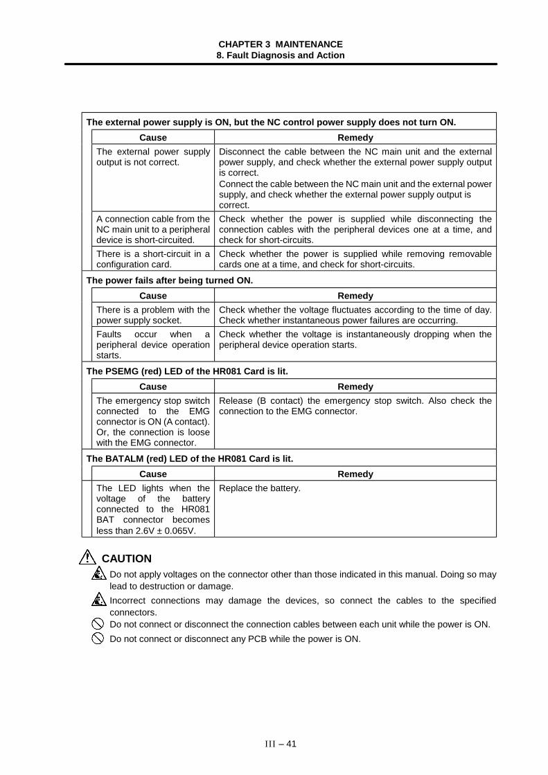
CHAPTER 3 MAINTENANCE8. Fault Diagnosis and Action
III – 41
The external power supply is ON, but the NC control power supply does not turn ON.Cause Remedy
The external power supplyoutput is not correct.
Disconnect the cable between the NC main unit and the externalpower supply, and check whether the external power supply outputis correct.Connect the cable between the NC main unit and the external powersupply, and check whether the external power supply output iscorrect.
A connection cable from theNC main unit to a peripheraldevice is short-circuited.
Check whether the power is supplied while disconnecting theconnection cables with the peripheral devices one at a time, andcheck for short-circuits.
There is a short-circuit in aconfiguration card.
Check whether the power is supplied while removing removablecards one at a time, and check for short-circuits.
The power fails after being turned ON.Cause Remedy
There is a problem with thepower supply socket.
Check whether the voltage fluctuates according to the time of day.Check whether instantaneous power failures are occurring.
Faults occur when aperipheral device operationstarts.
Check whether the voltage is instantaneously dropping when theperipheral device operation starts.
The PSEMG (red) LED of the HR081 Card is lit.Cause Remedy
The emergency stop switchconnected to the EMGconnector is ON (A contact).Or, the connection is loosewith the EMG connector.
Release (B contact) the emergency stop switch. Also check theconnection to the EMG connector.
The BATALM (red) LED of the HR081 Card is lit.Cause Remedy
The LED lights when thevoltage of the batteryconnected to the HR081BAT connector becomesless than 2.6V ± 0.065V.
Replace the battery.
CAUTIONDo not apply voltages on the connector other than those indicated in this manual. Doing so maylead to destruction or damage.Incorrect connections may damage the devices, so connect the cables to the specifiedconnectors.Do not connect or disconnect the connection cables between each unit while the power is ON.Do not connect or disconnect any PCB while the power is ON.
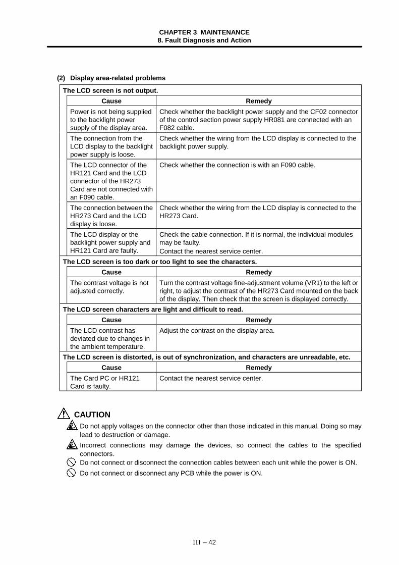
CHAPTER 3 MAINTENANCE8. Fault Diagnosis and Action
III – 42
(2) Display area-related problems
The LCD screen is not output.Cause Remedy
Power is not being suppliedto the backlight powersupply of the display area.
Check whether the backlight power supply and the CF02 connectorof the control section power supply HR081 are connected with anF082 cable.
The connection from theLCD display to the backlightpower supply is loose.
Check whether the wiring from the LCD display is connected to thebacklight power supply.
The LCD connector of theHR121 Card and the LCDconnector of the HR273Card are not connected withan F090 cable.
Check whether the connection is with an F090 cable.
The connection between theHR273 Card and the LCDdisplay is loose.
Check whether the wiring from the LCD display is connected to theHR273 Card.
The LCD display or thebacklight power supply andHR121 Card are faulty.
Check the cable connection. If it is normal, the individual modulesmay be faulty.Contact the nearest service center.
The LCD screen is too dark or too light to see the characters.Cause Remedy
The contrast voltage is notadjusted correctly.
Turn the contrast voltage fine-adjustment volume (VR1) to the left orright, to adjust the contrast of the HR273 Card mounted on the backof the display. Then check that the screen is displayed correctly.
The LCD screen characters are light and difficult to read.Cause Remedy
The LCD contrast hasdeviated due to changes inthe ambient temperature.
Adjust the contrast on the display area.
The LCD screen is distorted, is out of synchronization, and characters are unreadable, etc.Cause Remedy
The Card PC or HR121Card is faulty.
Contact the nearest service center.
CAUTIONDo not apply voltages on the connector other than those indicated in this manual. Doing so maylead to destruction or damage.Incorrect connections may damage the devices, so connect the cables to the specifiedconnectors.Do not connect or disconnect the connection cables between each unit while the power is ON.Do not connect or disconnect any PCB while the power is ON.
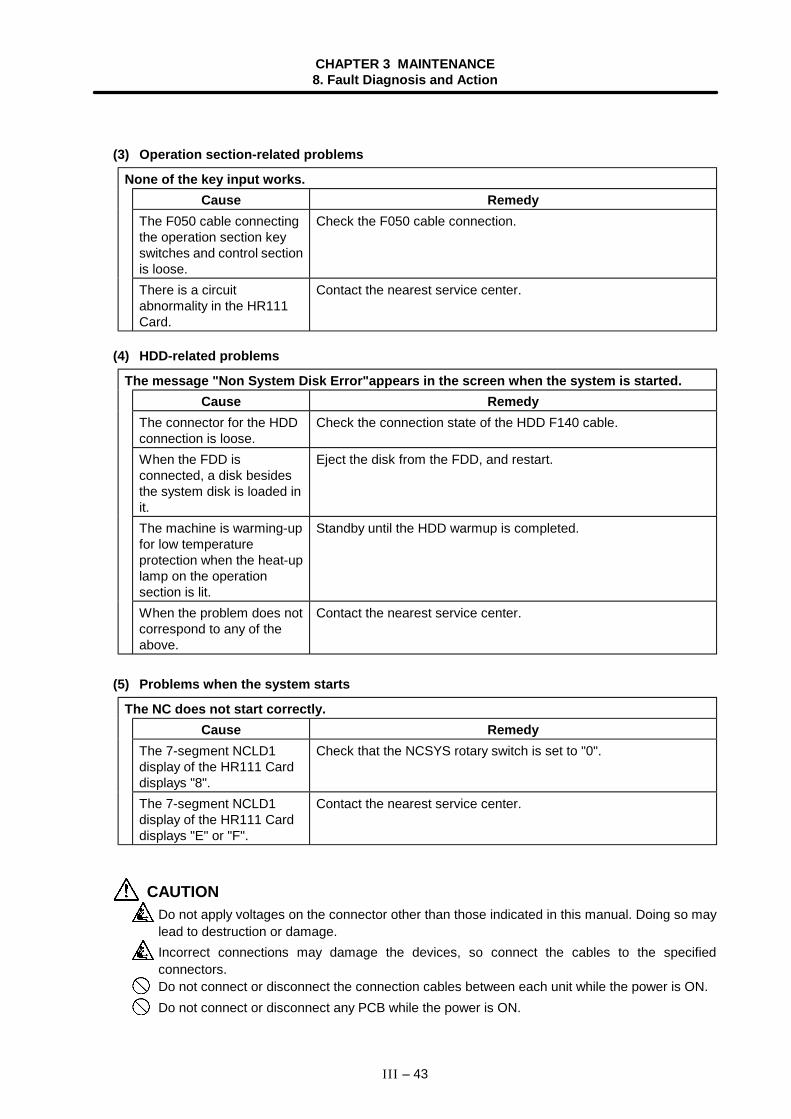
CHAPTER 3 MAINTENANCE8. Fault Diagnosis and Action
III – 43
(3) Operation section-related problems
None of the key input works.Cause Remedy
The F050 cable connectingthe operation section keyswitches and control sectionis loose.
Check the F050 cable connection.
There is a circuitabnormality in the HR111Card.
Contact the nearest service center.
(4) HDD-related problems
The message "Non System Disk Error"appears in the screen when the system is started.Cause Remedy
The connector for the HDDconnection is loose.
Check the connection state of the HDD F140 cable.
When the FDD isconnected, a disk besidesthe system disk is loaded init.
Eject the disk from the FDD, and restart.
The machine is warming-upfor low temperatureprotection when the heat-uplamp on the operationsection is lit.
Standby until the HDD warmup is completed.
When the problem does notcorrespond to any of theabove.
Contact the nearest service center.
(5) Problems when the system starts
The NC does not start correctly.Cause Remedy
The 7-segment NCLD1display of the HR111 Carddisplays "8".
Check that the NCSYS rotary switch is set to "0".
The 7-segment NCLD1display of the HR111 Carddisplays "E" or "F".
Contact the nearest service center.
CAUTIONDo not apply voltages on the connector other than those indicated in this manual. Doing so maylead to destruction or damage.Incorrect connections may damage the devices, so connect the cables to the specifiedconnectors.Do not connect or disconnect the connection cables between each unit while the power is ON.Do not connect or disconnect any PCB while the power is ON.
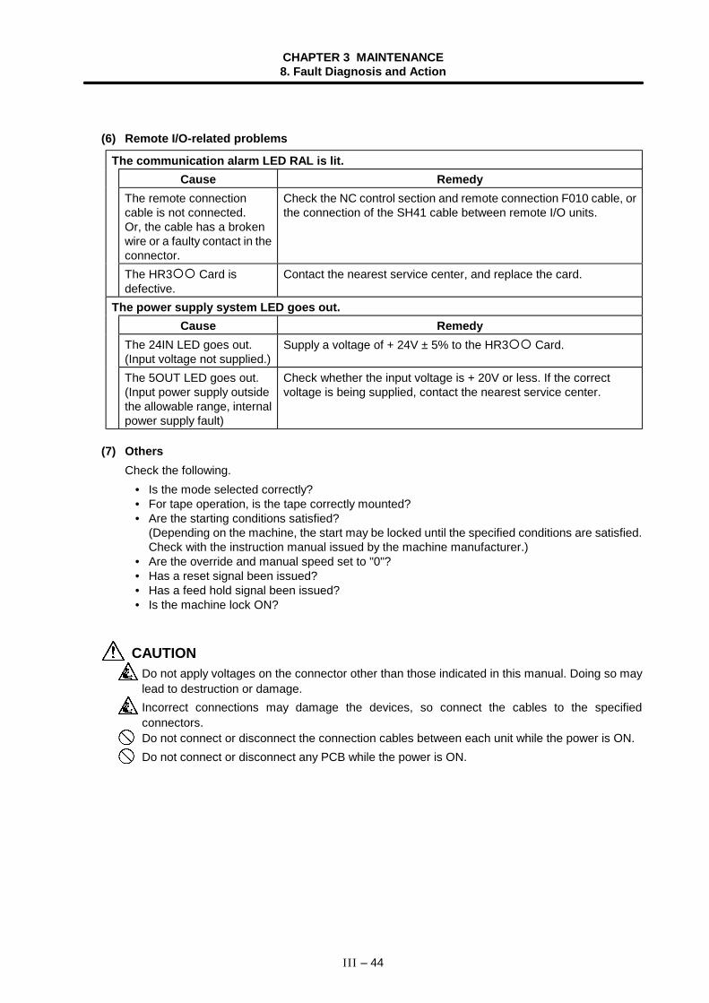
CHAPTER 3 MAINTENANCE8. Fault Diagnosis and Action
III – 44
(6) Remote I/O-related problems
The communication alarm LED RAL is lit.Cause Remedy
The remote connectioncable is not connected.Or, the cable has a brokenwire or a faulty contact in theconnector.
Check the NC control section and remote connection F010 cable, orthe connection of the SH41 cable between remote I/O units.
The HR3 Card isdefective.
Contact the nearest service center, and replace the card.
The power supply system LED goes out.Cause Remedy
The 24IN LED goes out.(Input voltage not supplied.)
Supply a voltage of + 24V ± 5% to the HR3 Card.
The 5OUT LED goes out.(Input power supply outsidethe allowable range, internalpower supply fault)
Check whether the input voltage is + 20V or less. If the correctvoltage is being supplied, contact the nearest service center.
(7) OthersCheck the following.
• Is the mode selected correctly?• For tape operation, is the tape correctly mounted?• Are the starting conditions satisfied?
(Depending on the machine, the start may be locked until the specified conditions are satisfied.Check with the instruction manual issued by the machine manufacturer.)
• Are the override and manual speed set to "0"?• Has a reset signal been issued?• Has a feed hold signal been issued?• Is the machine lock ON?
CAUTIONDo not apply voltages on the connector other than those indicated in this manual. Doing so maylead to destruction or damage.Incorrect connections may damage the devices, so connect the cables to the specifiedconnectors.Do not connect or disconnect the connection cables between each unit while the power is ON.Do not connect or disconnect any PCB while the power is ON.

CHAPTER 4 APPENDICES
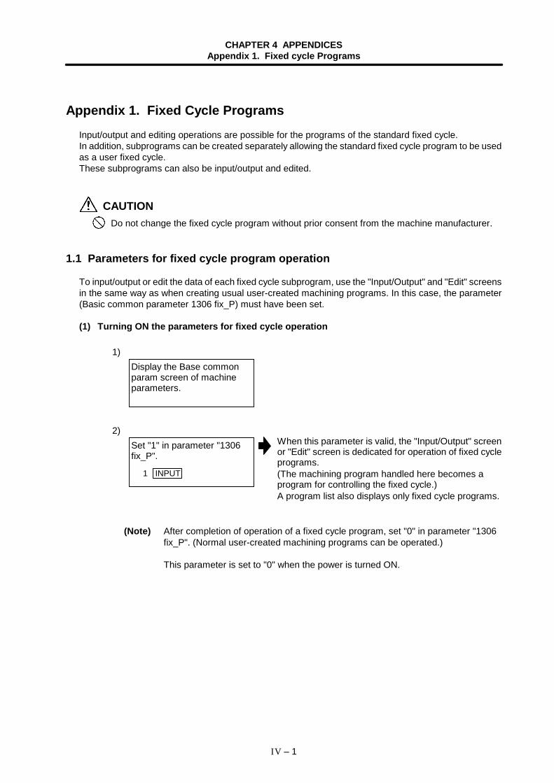
CHAPTER 4 APPENDICESAppendix 1. Fixed cycle Programs
IV – 1
Appendix 1. Fixed Cycle ProgramsInput/output and editing operations are possible for the programs of the standard fixed cycle.In addition, subprograms can be created separately allowing the standard fixed cycle program to be usedas a user fixed cycle.These subprograms can also be input/output and edited.
CAUTIONDo not change the fixed cycle program without prior consent from the machine manufacturer.
1.1 Parameters for fixed cycle program operation
To input/output or edit the data of each fixed cycle subprogram, use the "Input/Output" and "Edit" screensin the same way as when creating usual user-created machining programs. In this case, the parameter(Basic common parameter 1306 fix_P) must have been set.
(1) Turning ON the parameters for fixed cycle operation
1)
2)When this parameter is valid, the "Input/Output" screenor "Edit" screen is dedicated for operation of fixed cycleprograms.(The machining program handled here becomes aprogram for controlling the fixed cycle.)A program list also displays only fixed cycle programs.
(Note) After completion of operation of a fixed cycle program, set "0" in parameter "1306fix_P". (Normal user-created machining programs can be operated.)
This parameter is set to "0" when the power is turned ON.
Display the Base commonparam screen of machineparameters.
Set "1" in parameter "1306fix_P".
1 INPUT
CHAPTER 4 APPENDICESAppendix 1. Fixed cycle Programs
IV – 2
1.2 Inputting/outputting fixed cycle programs
Fixed cycle programs are transferred (input/output with an external device) on the Input/Output screen.Check that the parameter "1306 fix_P" for fixed cycle operation on the Base common param screen hasbeen set to "1".The operation method is the same as for transferring user machining programs.
(1) Inputting (External device →→→→ Memory)The operation method is the same as for user machining programs.Generally, a group of 12 fixed cycle subprograms constitutes a set and, therefore, greaterconvenience is afforded if programs are prepared in such a way that the data can be inputcontinuously.When the data transfer begins, the message "Transferring" appears. When the EOR code is read,the data transfer stops and the message "Transfer complete" appears.After programs have been input, they must be checked that the programs have been input correctlyon the program list and Edit screen.
(2) Outputting (Memory →→→→ External device)The operation method is the same as for user machining programs.There are two ways of outputting the fixed cycle programs which have been registered: output of oneprogram at a time or output of several programs in a batch.When the data transfer begins, the message "Transferring" appears. When the EOR code is read,the data transfer stops and the message "Transfer complete" appears.After programs have been output, they must be checked that there are no data output errors.
(3) ErasingThe operation method is the same as for user machining programs.There are two ways of erasing registered fixed cycle programs: Erasing one program at a time orerasing of several continuous programs in a batch.Designate the device, directory and No. of the program to be erased in the setting column A. Whenerasing of several continuous programs in a batch, designate the range of Nos. to be erased.If the data erasing process completes correctly, the message "Erase complete" is displayed.If some files remain that could not be erased when erasing several programs, the message "Eraseended. Some file not erased" is displayed.
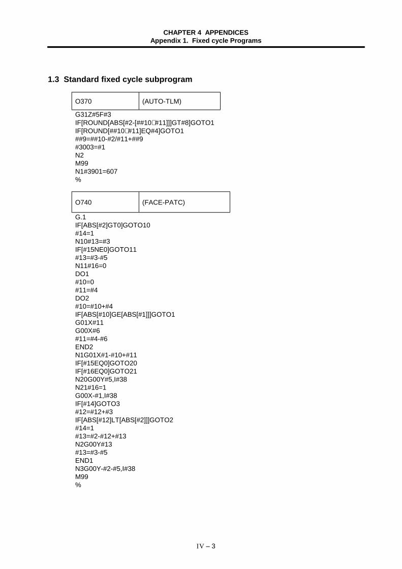
CHAPTER 4 APPENDICESAppendix 1. Fixed cycle Programs
IV – 3
1.3 Standard fixed cycle subprogram
O370 (AUTO-TLM)
G31Z#5F#3IF[ROUND[ABS[#2-[##10∗ #11]]]GT#8]GOTO1IF[ROUND[##10∗ #11]EQ#4]GOTO1##9=##10-#2/#11+##9#3003=#1N2M99N1#3901=607%
O740 (FACE-PATC)
G.1IF[ABS[#2]GT0]GOTO10#14=1N10#13=#3IF[#15NE0]GOTO11#13=#3-#5N11#16=0DO1#10=0#11=#4DO2#10=#10+#4IF[ABS[#10]GE[ABS[#1]]]GOTO1G01X#11G00X#6#11=#4-#6END2N1G01X#1-#10+#11IF[#15EQ0]GOTO20IF[#16EQ0]GOTO21N20G00Y#5,I#38N21#16=1G00X-#1,I#38IF[#14]GOTO3#12=#12+#3IF[ABS[#12]LT[ABS[#2]]]GOTO2#14=1#13=#2-#12+#13N2G00Y#13#13=#3-#5END1N3G00Y-#2-#5,I#38M99%
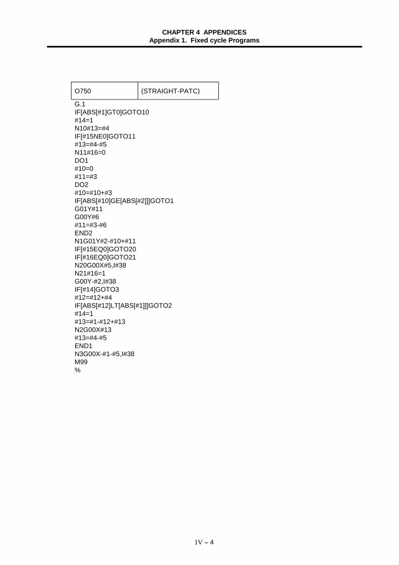
CHAPTER 4 APPENDICESAppendix 1. Fixed cycle Programs
IV – 4
O750 (STRAIGHT-PATC)
G.1IF[ABS[#1]GT0]GOTO10#14=1N10#13=#4IF[#15NE0]GOTO11#13=#4-#5N11#16=0DO1#10=0#11=#3DO2#10=#10+#3IF[ABS[#10]GE[ABS[#2]]]GOTO1G01Y#11G00Y#6#11=#3-#6END2N1G01Y#2-#10+#11IF[#15EQ0]GOTO20IF[#16EQ0]GOTO21N20G00X#5,I#38N21#16=1G00Y-#2,I#38IF[#14]GOTO3#12=#12+#4IF[ABS[#12]LT[ABS[#1]]]GOTO2#14=1#13=#1-#12+#13N2G00X#13#13=#4-#5END1N3G00X-#1-#5,I#38M99%
CHAPTER 4 APPENDICESAppendix 1. Fixed cycle Programs
IV – 5
O760 (THREAD-PATC)
G.1#12=1#13=#9IF[ABS[#13]GE[ABS[#8]]]GOTO1#16=1#13=#8N1#11=#13IF[ABS[#11]LT[ABS[#4-#5]]]GOTO2#11=#4-#5#14=1N2#17=#11#18=ROUND[[#4-#11-#5]∗ #7]IF[[#18XOR#1]GE0]GOTO10#18=-#18N10#19=#18#10=ROUND[[#11+#5]∗ #7]IF[[#10XOR#1]GE0]GOTO20#10=-#10N20G00X#10,I#38#20=#10DO1#15=ROUND[#10∗ #3/#1]N90G00Y#2+#3-#4-#15+#11G33X#1-#10-#18Y-#3+#15G00Y-#2+#4-#11,I#38IF[[#3902AND1]EQ0]GOTO91G00X#10+#18-#1,I#38GOTO90N91IF[#14GT0]GOTO3IF[#16GT0]GOTO7#12=#12+1#13=ROUND[#9∗ SQRT[#12]]IF[ABS[#13-#11]GE[ABS[#8]]]GOTO8#16=1N7#13=#11+#8N8#11=#13IF[ABS[#11]LT[ABS[#4-#5]]]GOTO9#11=#4-#5#14=1N9#10=ROUND[[#17-#11]∗ #7]IF[[#10XOR#1]GE0]GOTO6#10=-#10N6#10=#10+#20G00X-#1+#10+#18,I#38IF[#14LT0]GOTO11#18=0GOTO12
(Continued on the next page)
CHAPTER 4 APPENDICESAppendix 1. Fixed cycle Programs
IV – 6
N11#18=#19-#10+#20N12END1N3IF[ABS[#6]LT1]GOTO5#14=0#13=0DO2IF[#14GT0]GOTO5#13=#13+#6IF[ABS[#13]LT[ABS[#5]]]GOTO4#13=#5#14=1N4G00X#10-#1,I#38N92G00Y#2+#3-#4+#13-#15+#11G33X#1-#10Y-#3+#15G00Y-#2+#4-#13-#11,I#38IF[[#3902AND1]EQ0]GOTO93G00X#10-#1,I#38GOTO92N93END2N5G00X-#1,I#38M99%
O761 (THREAD-PATC-2SYSTE)
G.1N761!L10#12=1#13=#9IF[ABS[#13]GE[ABS[#8]]]GOTO1#16=1#13=#8N1#11=#13IF[ABS[#11]LT[ABS[#4-#5]]]GOTO2#11=#4-#5#14=1N2#17=#11#18=ROUND[[#4-#11-#5]∗ #7]IF[[#18XOR#1]GE0]GOTO10#18=-#18N10#19=#18#10=ROUND[[#11+#5]∗ #7]IF[[#10XOR#1]GE0]GOTO20#10=-#10N20G00X#10,I#38#20=#10DO1#15=ROUND[#10∗ #3/#1]G00Y#2+#3-#4-#15+#11!L11
CHAPTER 4 APPENDICESAppendix 1. Fixed cycle Programs
IV – 7
G33X#1-#10-#18Y-#3+#15G00Y-#2+#4-#11,I#38!L12IF[#14GT0]GOTO3IF[#16GT0]GOTO7#12=#12+1#13=ROUND[#9∗ SQRT[#12]]IF[ABS[#13-#11]GE[ABS[#8]]]GOTO8#16=1N7#13=#11+#8N8#11=#13IF[ABS[#11]LT[ABS[#4-#5]]]GOTO9#11=#4-#5#14=1N9#10=ROUND[[#17-#11]∗ #7]IF[[#10XOR#1]GE0]GOTO6#10=-#10N6#10=#10+#20G00X-#1+#10+#18,I#38IF[#14LT0]GOTO11#18=0GOTO12N11#18=#19-#10+#20N12END1N3IF[ABS[#6]LT1]GOTO5#14=0#13=0DO2IF[#14GT0]GOTO5#13=#13+#6IF[ABS[#13]LT[ABS[#5]]]GOTO4#13=#5#14=1N4G00X#10-#1,I#38G00Y#2+#3-#4+#13-#15+#11!L11G33X#1-#10Y-#3+#15G00Y-#2+#4-#13-#11,I#38!L12END2N5G00X-#1,I#38M99%
CHAPTER 4 APPENDICESAppendix 1. Fixed cycle Programs
IV – 8
O762 (THREAD-PATC-2SYSTE)
G.1N762!L10#12=1#13=#9IF[ABS[#13]GE[ABS[#8]]]GOTO1#16=1#13=#8N1#11=#13IF[ABS[#11]LT[ABS[#4-#5]]]GOTO2#11=#4-#5#14=1N2#17=#11#18=ROUND[[#4-#11-#5]∗ #7]IF[[#18XOR#1]GE0]GOTO10#18=-#18N10#19=#18#10=ROUND[[#11+#5]∗ #7]IF[[#10XOR#1]GE0]GOTO20#10=-#10N20IF[#27NE1]GOTO21G00X#10,I#38N21#20=#10#28=1DO1#15=ROUND[#10∗ #3/#1]#29=#28MOD2IF[[#27EQ1]AND[#29EQ0]]GOTO22IF[[#27EQ2]AND[#29EQ1]]GOTO22G00Y#2+#3-#4-#15+#11!L11G33X#1-#10-#18Y-#3+#15G00Y-#2+#4-#11,I#38#21=#18!L12N22IF[#14GT0]GOTO3IF[#16GT0]GOTO7#12=#12+1#13=ROUND[#9∗ SQRT[#12]]IF[ABS[#13-#11]GE[ABS[#8]]]GOTO8#16=1N7#13=#11+#8N8#11=#13IF[ABS[#11]LT[ABS[#4-#5]]]GOTO9#11=#4-#5#14=1N9#10=ROUND[[#17-#11]∗ #7]IF[[#10XOR#1]GE0]GOTO6#10=-#10
CHAPTER 4 APPENDICESAppendix 1. Fixed cycle Programs
IV – 9
N6#10=#10+#20IF[[#27EQ1]AND[#29EQ1]]GOTO24IF[[#27EQ2]AND[#29EQ0]]GOTO24IF[[#27EQ2]AND[#28EQ1]]GOTO23G00X-#1+#10+#21,I#38GOTO24N23G00X#10,I#38N24IF[#14LT1]GOTO11#18=0GOTO12N11#18=#19-#10+#20N12#28=#28+1END1N3IF[ABS[#6]LT1]GOTO5#14=0#13=0DO2IF[#14GT0]GOTO5#13=#13+#6IF[ABS[#13]LT[ABS[#5]]]GOTO4#13=#5#14=1N4#29=#28MOD2IF[[#27EQ1]AND[#29EQ1]]GOTO25IF[[#27EQ2]AND[#29EQ0]]GOTO25G00X#10-#1+#21,I#38#21=0G00Y#2+#3-#4+#13-#15+#11!L11G33X#1-#10Y-#3+#15G00Y-#2+#4-#13-#11,I#38!L12N25#28=#28+1END2N5G00X-#1,I#38M99%
CHAPTER 4 APPENDICESAppendix 1. Fixed cycle Programs
IV – 10
O770 (STRAIGHT-TURNING)
G.1IF[[#1EQ0]OR[#2EQ0]]GOTO1Y#2+#7G1X#1Y-#7Y-#2G0X-#1,I#38N1M99%
O780 (THREAD-CUTTING)
G.1IF[[#1EQ0]OR[#2EQ0]]GOTO1N90Y#2+#7G33X#1Y-#7F#9E#10G0Y-#2,I#38IF[[#3902AND1]EQ0]GOTO91G00X-#1,I#38GOTO90N91X-#1,I#38N1M99%
O790 (FACE-CUTTING)
G.1IF[[#1EQ0]OR[#2EQ0]]GOTO1X#1+#7G1X-#7Y#2X-#1G0Y-#2,I#38N1M99%
CHAPTER 4 APPENDICESAppendix 1. Fixed cycle Programs
IV – 11
O830 (DRILL-CYCLE-B)
G.1IF[#30]GOTO2M#24#29=#11#28=0Z#2#2=##5#3003=#8OR1DO1#28=#28-#11#26=-#28-#29Z#26IF[ABS[#28]GE[ABS[#3]]]GOTO1G1Z#29G0Z#28,I#38#29=#11+#14END1N1G1Z#3-#26G4P#4#3003=#8G0Z-#3-#2,I#38IF[#24EQ#0]GOTO2M#24+1G4P#21N2M99%
O831 (DRILL-CYCLE-A)
G.1IF[#30]GOTO2M#24#29=0#28=#11Z#2#2=##5#3003=#8OR1DO1#29=#29+#11IF[ABS[#29]GE[ABS[#3]]]GOTO1G1Z#28G0Z-#14#28=#11+#14END1N1G1Z#3-#29+#28G4P#4#3003=#8G0Z-#3-#2,I#38IF[#24EQ#0]GOTO2M#24+1G4P#21N2M99%
CHAPTER 4 APPENDICESAppendix 1. Fixed cycle Programs
IV – 12
O832 (DEEP-DRILL-CYCLE-2)
G.1IF[#30]GOTO3#3003=#8OR1#29=#12#28=0G0Z#2IF[#12NE#0]GOTO1IF[#11EQ#0]GOTO2N1#28=#28-#12#26=-#28-#29IF[ABS[#28]GE[ABS[#3]]]GOTO2G1Z#12G4P#4G0Z#28-#2,I#38G4P#13#29=#11+#15DO1#28=#28-#11#26=-#28-#29G0Z#26+#2IF[ABS[#28]GE[ABS[#3]]]GOTO2G1Z#29G4P#4G0Z#28-#2,I#38G4P#13END1N2G1Z#3-#26G4P#4#3003=#8G0Z-#3-#2,I#38N3M99%
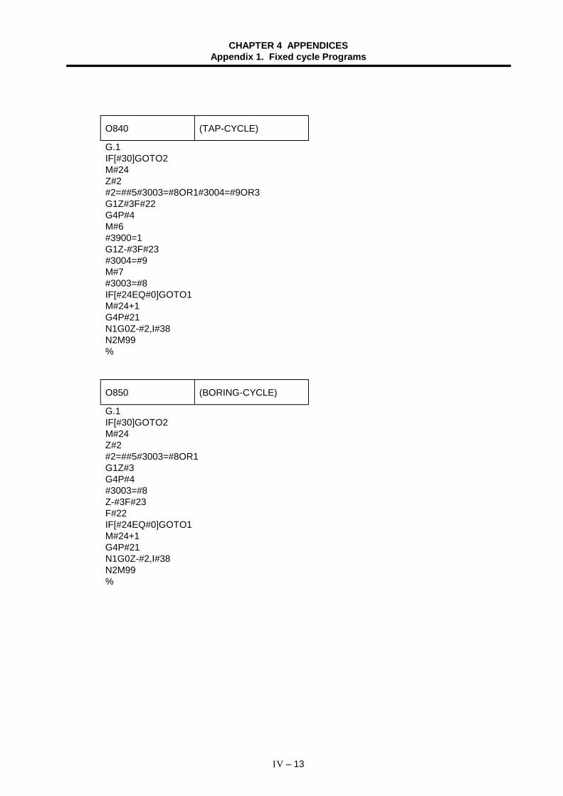
CHAPTER 4 APPENDICESAppendix 1. Fixed cycle Programs
IV – 13
O840 (TAP-CYCLE)
G.1IF[#30]GOTO2M#24Z#2#2=##5#3003=#8OR1#3004=#9OR3G1Z#3F#22G4P#4M#6#3900=1G1Z-#3F#23#3004=#9M#7#3003=#8IF[#24EQ#0]GOTO1M#24+1G4P#21N1G0Z-#2,I#38N2M99%
O850 (BORING-CYCLE)
G.1IF[#30]GOTO2M#24Z#2#2=##5#3003=#8OR1G1Z#3G4P#4#3003=#8Z-#3F#23F#22IF[#24EQ#0]GOTO1M#24+1G4P#21N1G0Z-#2,I#38N2M99%
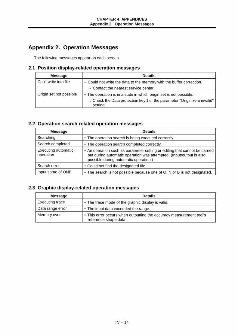
CHAPTER 4 APPENDICESAppendix 2. Operation Messages
IV – 14
Appendix 2. Operation MessagesThe following messages appear on each screen.
2.1 Position display-related operation messagesMessage Details
Can't write into file • Could not write the data to the memory with the buffer correction.→ Contact the nearest service center.
Origin set not possible • The operation is in a state in which origin set is not possible.→ Check the Data protection key 1 or the parameter "Origin zero invalid"
setting.
2.2 Operation search-related operation messagesMessage Details
Searching • The operation search is being executed correctly.Search completed • The operation search completed correctly.Executing automaticoperation
• An operation such as parameter setting or editing that cannot be carriedout during automatic operation was attempted. (Input/output is alsopossible during automatic operation.)
Search error • Could not find the designated file.Input some of ONB • The search is not possible because one of O, N or B is not designated.
2.3 Graphic display-related operation messagesMessage Details
Executing trace • The trace mode of the graphic display is valid.Data range error • The input data exceeded the range.Memory over • This error occurs when outputting the accuracy measurement tool's
reference shape data.
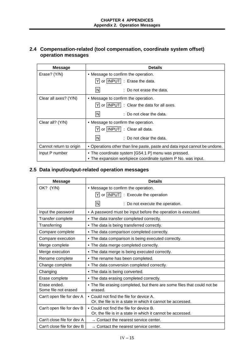
CHAPTER 4 APPENDICESAppendix 2. Operation Messages
IV – 15
2.4 Compensation-related (tool compensation, coordinate system offset)operation messages
Message DetailsErase? (Y/N) • Message to confirm the operation.
Y or INPUT : Erase the data.
N : Do not erase the data.
Clear all axes? (Y/N) • Message to confirm the operation.Y or INPUT : Clear the data for all axes.
N : Do not clear the data.
Clear all? (Y/N) • Message to confirm the operation.Y or INPUT : Clear all data.
N : Do not clear the data.
Cannot return to origin • Operations other than line paste, paste and data input cannot be undone.Input P number • The coordinate system [G54.1 P] menu was pressed.
• The expansion workpiece coordinate system P No. was input.
2.5 Data input/output-related operation messages
Message DetailsOK? (Y/N) • Message to confirm the operation.
Y or INPUT : Execute the operation
N : Do not execute the operation.
Input the password • A password must be input before the operation is executed.Transfer complete • The data transfer completed correctly.Transferring • The data is being transferred correctly.Compare complete • The data comparison completed correctly.Compare execution • The data comparison is being executed correctly.Merge complete • The data merge completed correctly.Merge execution • The data merge is being executed correctly.Rename complete • The rename has been completed.Change complete • The data conversion completed correctly.Changing • The data is being converted.Erase complete • The data erasing completed correctly.Erase ended.Some file not erased
• The file erasing completed, but there are some files that could not beerased.
Can't open file for dev A • Could not find the file for device A.Or, the file is in a state in which it cannot be accessed.
Can't open file for dev B • Could not find the file for device B.Or, the file is in a state in which it cannot be accessed.
Can't close file for dev A → Contact the nearest service center.Can't close file for dev B → Contact the nearest service center.
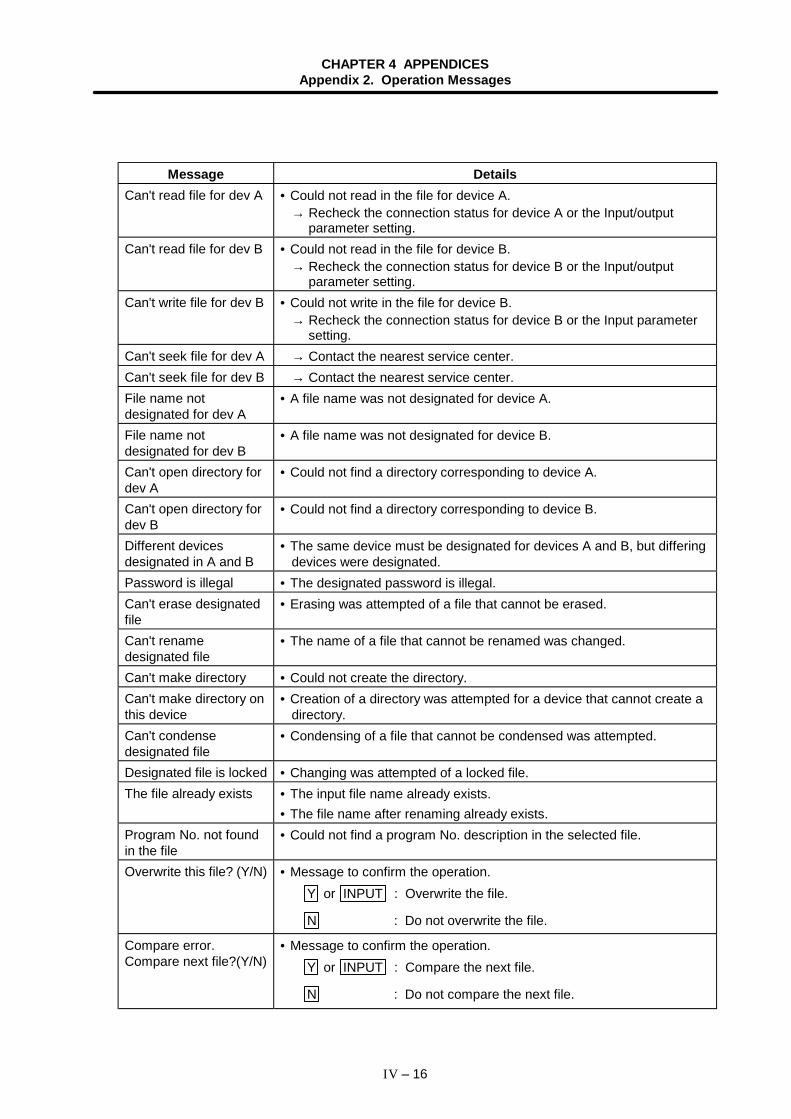
CHAPTER 4 APPENDICESAppendix 2. Operation Messages
IV – 16
Message DetailsCan't read file for dev A • Could not read in the file for device A.
→ Recheck the connection status for device A or the Input/outputparameter setting.
Can't read file for dev B • Could not read in the file for device B.→ Recheck the connection status for device B or the Input/output
parameter setting.Can't write file for dev B • Could not write in the file for device B.
→ Recheck the connection status for device B or the Input parametersetting.
Can't seek file for dev A → Contact the nearest service center.Can't seek file for dev B → Contact the nearest service center.File name notdesignated for dev A
• A file name was not designated for device A.
File name notdesignated for dev B
• A file name was not designated for device B.
Can't open directory fordev A
• Could not find a directory corresponding to device A.
Can't open directory fordev B
• Could not find a directory corresponding to device B.
Different devicesdesignated in A and B
• The same device must be designated for devices A and B, but differingdevices were designated.
Password is illegal • The designated password is illegal.Can't erase designatedfile
• Erasing was attempted of a file that cannot be erased.
Can't renamedesignated file
• The name of a file that cannot be renamed was changed.
Can't make directory • Could not create the directory.Can't make directory onthis device
• Creation of a directory was attempted for a device that cannot create adirectory.
Can't condensedesignated file
• Condensing of a file that cannot be condensed was attempted.
Designated file is locked • Changing was attempted of a locked file.The file already exists • The input file name already exists.
• The file name after renaming already exists.Program No. not foundin the file
• Could not find a program No. description in the selected file.
Overwrite this file? (Y/N) • Message to confirm the operation.Y or INPUT : Overwrite the file.
N : Do not overwrite the file.
Compare error.Compare next file?(Y/N)
• Message to confirm the operation.Y or INPUT : Compare the next file.
N : Do not compare the next file.
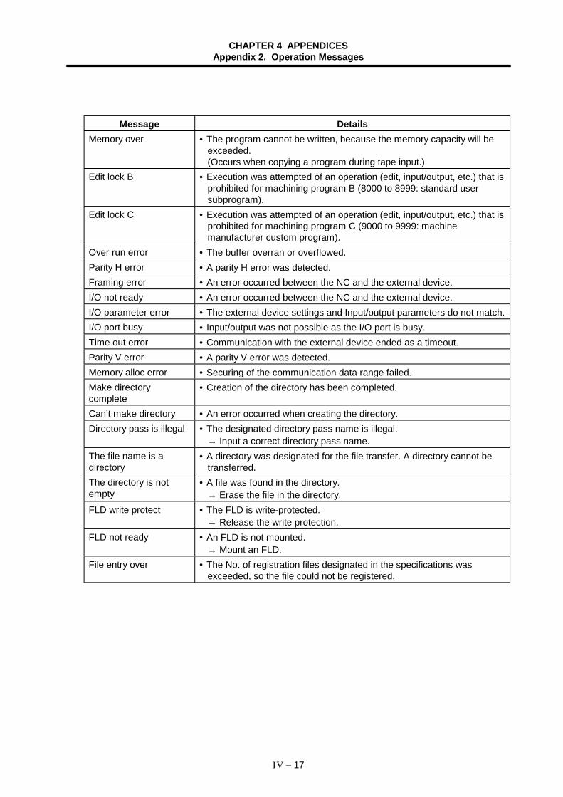
CHAPTER 4 APPENDICESAppendix 2. Operation Messages
IV – 17
Message DetailsMemory over • The program cannot be written, because the memory capacity will be
exceeded.(Occurs when copying a program during tape input.)
Edit lock B • Execution was attempted of an operation (edit, input/output, etc.) that isprohibited for machining program B (8000 to 8999: standard usersubprogram).
Edit lock C • Execution was attempted of an operation (edit, input/output, etc.) that isprohibited for machining program C (9000 to 9999: machinemanufacturer custom program).
Over run error • The buffer overran or overflowed.Parity H error • A parity H error was detected.Framing error • An error occurred between the NC and the external device.I/O not ready • An error occurred between the NC and the external device.I/O parameter error • The external device settings and Input/output parameters do not match.I/O port busy • Input/output was not possible as the I/O port is busy.Time out error • Communication with the external device ended as a timeout.Parity V error • A parity V error was detected.Memory alloc error • Securing of the communication data range failed.Make directorycomplete
• Creation of the directory has been completed.
Can’t make directory • An error occurred when creating the directory.Directory pass is illegal • The designated directory pass name is illegal.
→ Input a correct directory pass name.The file name is adirectory
• A directory was designated for the file transfer. A directory cannot betransferred.
The directory is notempty
• A file was found in the directory. → Erase the file in the directory.
FLD write protect • The FLD is write-protected. → Release the write protection.
FLD not ready • An FLD is not mounted. → Mount an FLD.
File entry over • The No. of registration files designated in the specifications wasexceeded, so the file could not be registered.
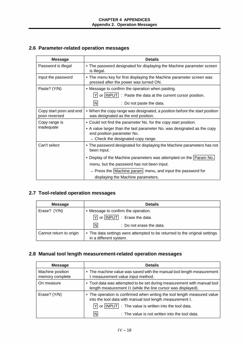
CHAPTER 4 APPENDICESAppendix 2. Operation Messages
IV – 18
2.6 Parameter-related operation messages
Message DetailsPassword is illegal • The password designated for displaying the Machine parameter screen
is illegal.Input the password • The menu key for first displaying the Machine parameter screen was
pressed after the power was turned ON.Paste? (Y/N) • Message to confirm the operation when pasting.
Y or INPUT : Paste the data at the current cursor position.
N : Do not paste the data.
Copy start posn and endposn reversed
• When the copy range was designated, a position before the start positionwas designated as the end position.
Copy range isinadequate
• Could not find the parameter No. for the copy start position.• A value larger than the last parameter No. was designated as the copy
end position parameter No.→ Check the designated copy range.
Can't select • The password designated for displaying the Machine parameters has notbeen input.
• Display of the Machine parameters was attempted on the Param No.menu, but the password has not been input.→ Press the Machine param menu, and input the password for
displaying the Machine parameters.
2.7 Tool-related operation messages
Message DetailsErase? (Y/N) • Message to confirm the operation.
Y or INPUT : Erase the data
N : Do not erase the data.
Cannot return to origin • The data settings were attempted to be returned to the original settingsin a different system.
2.8 Manual tool length measurement-related operation messages
Message DetailsMachine positionmemory complete
• The machine value was saved with the manual tool length measurementI measurement value input method.
On measure • Tool data was attempted to be set during measurement with manual toollength measurement II (while the line cursor was displayed).
Erase? (Y/N) • The operation is confirmed when writing the tool length measured valueinto the tool data with manual tool length measurement I.
Y or INPUT : The value is written into the tool data.
N : The value is not written into the tool data.
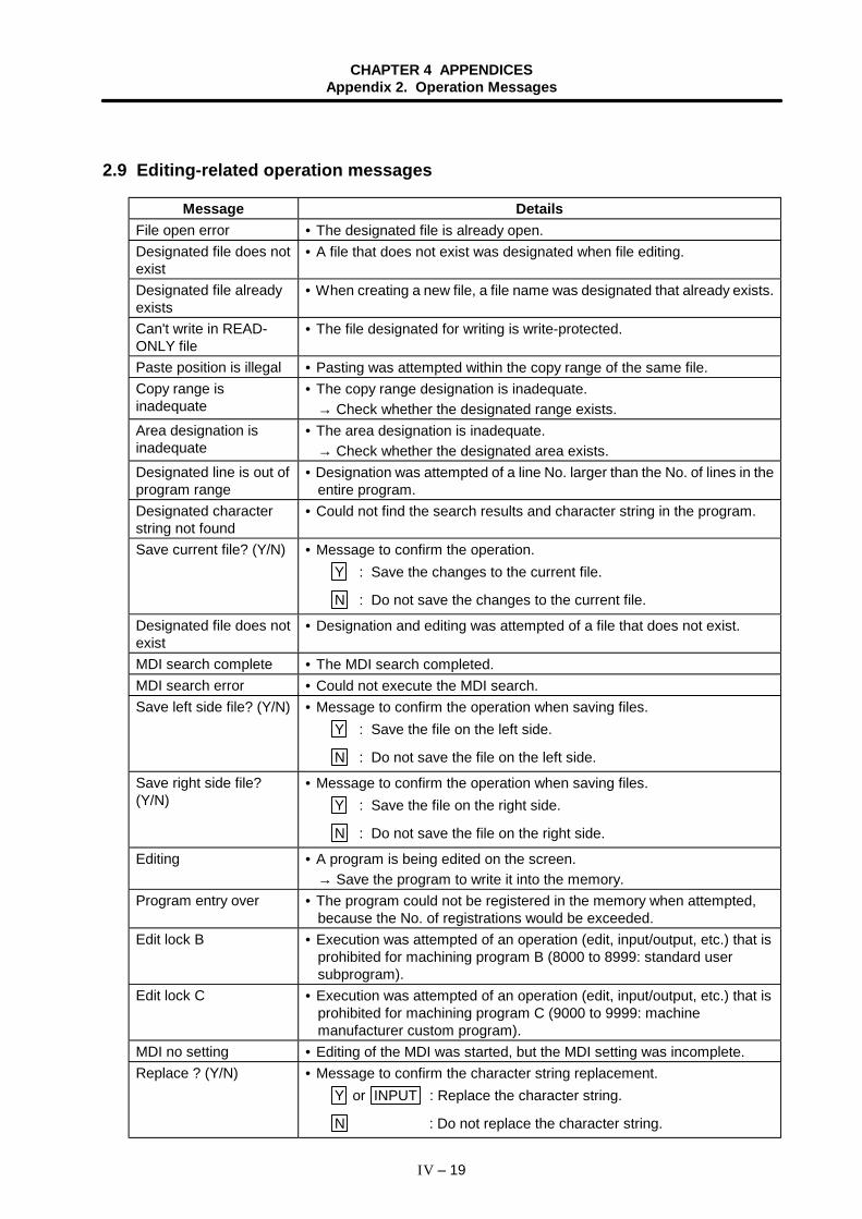
CHAPTER 4 APPENDICESAppendix 2. Operation Messages
IV – 19
2.9 Editing-related operation messages
Message DetailsFile open error • The designated file is already open.Designated file does notexist
• A file that does not exist was designated when file editing.
Designated file alreadyexists
• When creating a new file, a file name was designated that already exists.
Can't write in READ-ONLY file
• The file designated for writing is write-protected.
Paste position is illegal • Pasting was attempted within the copy range of the same file.Copy range isinadequate
• The copy range designation is inadequate.→ Check whether the designated range exists.
Area designation isinadequate
• The area designation is inadequate.→ Check whether the designated area exists.
Designated line is out ofprogram range
• Designation was attempted of a line No. larger than the No. of lines in theentire program.
Designated characterstring not found
• Could not find the search results and character string in the program.
Save current file? (Y/N) • Message to confirm the operation.Y : Save the changes to the current file.
N : Do not save the changes to the current file.
Designated file does notexist
• Designation and editing was attempted of a file that does not exist.
MDI search complete • The MDI search completed.MDI search error • Could not execute the MDI search.Save left side file? (Y/N) • Message to confirm the operation when saving files.
Y : Save the file on the left side.
N : Do not save the file on the left side.
Save right side file?(Y/N)
• Message to confirm the operation when saving files.Y : Save the file on the right side.
N : Do not save the file on the right side.
Editing • A program is being edited on the screen.→ Save the program to write it into the memory.
Program entry over • The program could not be registered in the memory when attempted,because the No. of registrations would be exceeded.
Edit lock B • Execution was attempted of an operation (edit, input/output, etc.) that isprohibited for machining program B (8000 to 8999: standard usersubprogram).
Edit lock C • Execution was attempted of an operation (edit, input/output, etc.) that isprohibited for machining program C (9000 to 9999: machinemanufacturer custom program).
MDI no setting • Editing of the MDI was started, but the MDI setting was incomplete.Replace ? (Y/N) • Message to confirm the character string replacement.
Y or INPUT : Replace the character string.
N : Do not replace the character string.
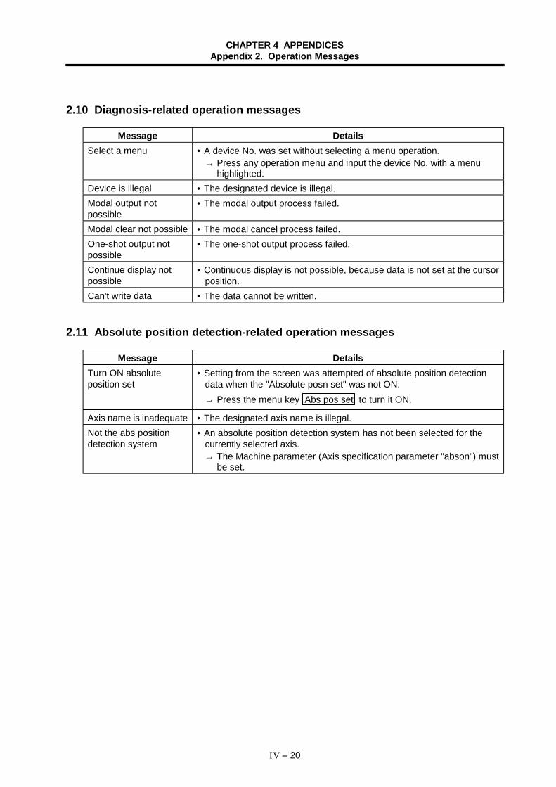
CHAPTER 4 APPENDICESAppendix 2. Operation Messages
IV – 20
2.10 Diagnosis-related operation messages
Message DetailsSelect a menu • A device No. was set without selecting a menu operation.
→ Press any operation menu and input the device No. with a menuhighlighted.
Device is illegal • The designated device is illegal.Modal output notpossible
• The modal output process failed.
Modal clear not possible • The modal cancel process failed.One-shot output notpossible
• The one-shot output process failed.
Continue display notpossible
• Continuous display is not possible, because data is not set at the cursorposition.
Can't write data • The data cannot be written.
2.11 Absolute position detection-related operation messages
Message DetailsTurn ON absoluteposition set
• Setting from the screen was attempted of absolute position detectiondata when the "Absolute posn set" was not ON.→ Press the menu key Abs pos set to turn it ON.
Axis name is inadequate • The designated axis name is illegal.Not the abs positiondetection system
• An absolute position detection system has not been selected for thecurrently selected axis.→ The Machine parameter (Axis specification parameter "abson") must
be set.
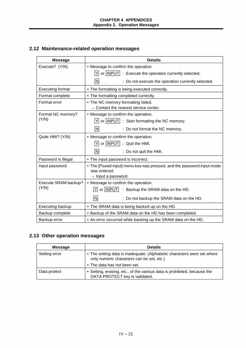
CHAPTER 4 APPENDICESAppendix 2. Operation Messages
IV – 21
2.12 Maintenance-related operation messages
Message DetailsExecute? (Y/N) • Message to confirm the operation.
Y or INPUT : Execute the operation currently selected.
N : Do not execute the operation currently selected.
Executing format • The formatting is being executed correctly.Format complete • The formatting completed correctly.Format error • The NC memory formatting failed.
→ Contact the nearest service center.Format NC memory?(Y/N)
• Message to confirm the operation.Y or INPUT : Start formatting the NC memory.
N : Do not format the NC memory.
Quite HMI? (Y/N) • Message to confirm the operation.Y or INPUT : Quit the HMI.
N : Do not quit the HMI.
Password is illegal • The input password is incorrect.Input password • The [Psswd input] menu key was pressed, and the password input mode
was entered.→ Input a password.
Execute SRAM backup?(Y/N)
• Message to confirm the operation.Y or INPUT : Backup the SRAM data on the HD.
N : Do not backup the SRAM data on the HD.
Executing backup • The SRAM data is being backed up on the HD.Backup complete • Backup of the SRAM data on the HD has been completed.Backup error • An error occurred while backing up the SRAM data on the HD.
2.13 Other operation messages
Message DetailsSetting error • The setting data is inadequate. (Alphabetic characters were set where
only numeric characters can be set, etc.)• The data has not been set.
Data protect • Setting, erasing, etc., of the various data is prohibited, because theDATA PROTECT key is validated.
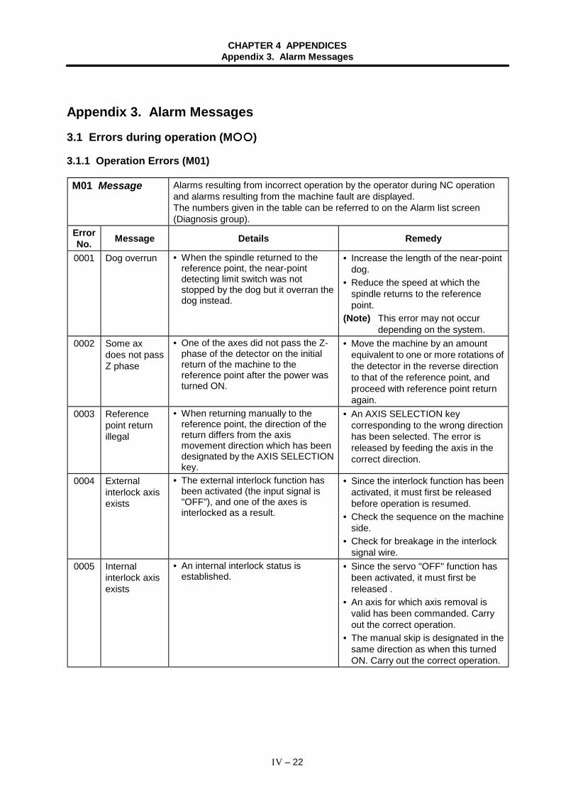
CHAPTER 4 APPENDICESAppendix 3. Alarm Messages
IV – 22
Appendix 3. Alarm Messages
3.1 Errors during operation (M )
3.1.1 Operation Errors (M01)
M01 Message Alarms resulting from incorrect operation by the operator during NC operationand alarms resulting from the machine fault are displayed.The numbers given in the table can be referred to on the Alarm list screen(Diagnosis group).
ErrorNo. Message Details Remedy
0001 Dog overrun • When the spindle returned to thereference point, the near-pointdetecting limit switch was notstopped by the dog but it overran thedog instead.
• Increase the length of the near-pointdog.
• Reduce the speed at which thespindle returns to the referencepoint.
(Note) This error may not occurdepending on the system.
0002 Some axdoes not passZ phase
• One of the axes did not pass the Z-phase of the detector on the initialreturn of the machine to thereference point after the power wasturned ON.
• Move the machine by an amountequivalent to one or more rotations ofthe detector in the reverse directionto that of the reference point, andproceed with reference point returnagain.
0003 Referencepoint returnillegal
• When returning manually to thereference point, the direction of thereturn differs from the axismovement direction which has beendesignated by the AXIS SELECTIONkey.
• An AXIS SELECTION keycorresponding to the wrong directionhas been selected. The error isreleased by feeding the axis in thecorrect direction.
0004 Externalinterlock axisexists
• The external interlock function hasbeen activated (the input signal is"OFF"), and one of the axes isinterlocked as a result.
• Since the interlock function has beenactivated, it must first be releasedbefore operation is resumed.
• Check the sequence on the machineside.
• Check for breakage in the interlocksignal wire.
0005 Internalinterlock axisexists
• An internal interlock status isestablished.
• Since the servo "OFF" function hasbeen activated, it must first bereleased .
• An axis for which axis removal isvalid has been commanded. Carryout the correct operation.
• The manual skip is designated in thesame direction as when this turnedON. Carry out the correct operation.
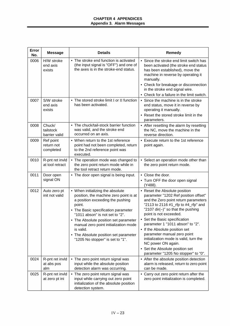
CHAPTER 4 APPENDICESAppendix 3. Alarm Messages
IV – 23
ErrorNo. Message Details Remedy
0006 H/W strokeend axisexists
• The stroke end function is activated(the input signal is "OFF") and one ofthe axes is in the stroke-end status.
• Since the stroke end limit switch hasbeen activated (the stroke end statushas been established), move themachine in reverse by operating itmanually.
• Check for breakage or disconnectionin the stroke end signal wire.
• Check for a failure in the limit switch.0007 S/W stroke
end axisexists
• The stored stroke limit I or II functionhas been activated.
• Since the machine is in the strokeend status, move it in reverse byoperating it manually.
• Reset the stored stroke limit in theparameters.
0008 Chuck/tailstockbarrier valid
• The chuck/tail-stock barrier functionwas valid, and the stroke endoccurred on an axis.
• After resetting the alarm by resettingthe NC, move the machine in thereverse direction.
0009 Ref pointreturn notcompleted
• When return to the 1st referencepoint had not been completed, returnto the 2nd reference point wasexecuted.
• Execute return to the 1st referencepoint again.
0010 R-pnt ret invldat tool retract
• The operation mode was changed tothe zero point return mode while inthe tool retract return mode.
• Select an operation mode other thanthe zero point return mode.
0011 Door opensignal ON
• The door open signal is being input. • Close the door.• Turn OFF the door open signal
(Y488).0012 Auto zero pt
init not valid• When initializing the absolute
position, the machine zero point is ata position exceeding the pushingpoint.
• The Basic specification parameter"1011 abson" is not set to "2".
• The Absolute position set parametermanual zero point initialization modeis valid.
• The Absolute position set parameter"1205 No stopper" is set to "1".
• Reset the Absolute positionparameter "1202 Ref position offset"and the Zero point return parameters"2113 to 2116 #1_rfp to #4_rfp" and"2107 dir(–)" so that the pushingpoint is not exceeded.
• Set the Basic specificationparameter 1 "1011 abson" to "2".
• If the Absolute position setparameter manual zero pointinitialization mode is valid, turn theNC power ON again.
• Set the Absolute position setparameter "1205 No stopper" to "0".
0024 R-pnt ret invldat abs posalm
• The zero point return signal wasinput while the absolute positiondetection alarm was occurring.
• After the absolute position detectionalarm is released, return to zero pointcan be made.
0025 R-pnt ret invldat zero pt ini
• The zero point return signal wasinput while carrying out zero pointinitialization of the absolute positiondetection system.
• Carry out zero point return after thezero point initialization is completed.
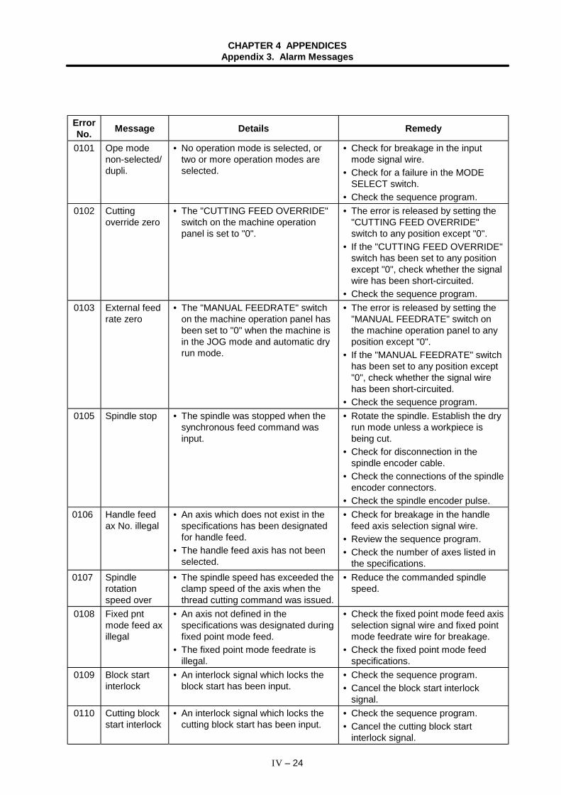
CHAPTER 4 APPENDICESAppendix 3. Alarm Messages
IV – 24
ErrorNo. Message Details Remedy
0101 Ope modenon-selected/dupli.
• No operation mode is selected, ortwo or more operation modes areselected.
• Check for breakage in the inputmode signal wire.
• Check for a failure in the MODESELECT switch.
• Check the sequence program.0102 Cutting
override zero• The "CUTTING FEED OVERRIDE"
switch on the machine operationpanel is set to "0".
• The error is released by setting the"CUTTING FEED OVERRIDE"switch to any position except "0".
• If the "CUTTING FEED OVERRIDE"switch has been set to any positionexcept "0", check whether the signalwire has been short-circuited.
• Check the sequence program.0103 External feed
rate zero• The "MANUAL FEEDRATE" switch
on the machine operation panel hasbeen set to "0" when the machine isin the JOG mode and automatic dryrun mode.
• The error is released by setting the"MANUAL FEEDRATE" switch onthe machine operation panel to anyposition except "0".
• If the "MANUAL FEEDRATE" switchhas been set to any position except"0", check whether the signal wirehas been short-circuited.
• Check the sequence program.0105 Spindle stop • The spindle was stopped when the
synchronous feed command wasinput.
• Rotate the spindle. Establish the dryrun mode unless a workpiece isbeing cut.
• Check for disconnection in thespindle encoder cable.
• Check the connections of the spindleencoder connectors.
• Check the spindle encoder pulse.0106 Handle feed
ax No. illegal• An axis which does not exist in the
specifications has been designatedfor handle feed.
• The handle feed axis has not beenselected.
• Check for breakage in the handlefeed axis selection signal wire.
• Review the sequence program.• Check the number of axes listed in
the specifications.0107 Spindle
rotationspeed over
• The spindle speed has exceeded theclamp speed of the axis when thethread cutting command was issued.
• Reduce the commanded spindlespeed.
0108 Fixed pntmode feed axillegal
• An axis not defined in thespecifications was designated duringfixed point mode feed.
• The fixed point mode feedrate isillegal.
• Check the fixed point mode feed axisselection signal wire and fixed pointmode feedrate wire for breakage.
• Check the fixed point mode feedspecifications.
0109 Block startinterlock
• An interlock signal which locks theblock start has been input.
• Check the sequence program.• Cancel the block start interlock
signal.0110 Cutting block
start interlock• An interlock signal which locks the
cutting block start has been input.• Check the sequence program.• Cancel the cutting block start
interlock signal.
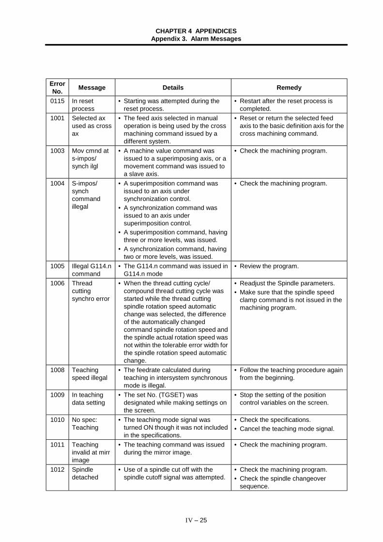
CHAPTER 4 APPENDICESAppendix 3. Alarm Messages
IV – 25
ErrorNo. Message Details Remedy
0115 In resetprocess
• Starting was attempted during thereset process.
• Restart after the reset process iscompleted.
1001 Selected axused as crossax
• The feed axis selected in manualoperation is being used by the crossmachining command issued by adifferent system.
• Reset or return the selected feedaxis to the basic definition axis for thecross machining command.
1003 Mov cmnd ats-impos/synch ilgl
• A machine value command wasissued to a superimposing axis, or amovement command was issued toa slave axis.
• Check the machining program.
1004 S-impos/synchcommandillegal
• A superimposition command wasissued to an axis undersynchronization control.
• A synchronization command wasissued to an axis undersuperimposition control.
• A superimposition command, havingthree or more levels, was issued.
• A synchronization command, havingtwo or more levels, was issued.
• Check the machining program.
1005 Illegal G114.ncommand
• The G114.n command was issued inG114.n mode
• Review the program.
1006 Threadcuttingsynchro error
• When the thread cutting cycle/compound thread cutting cycle wasstarted while the thread cuttingspindle rotation speed automaticchange was selected, the differenceof the automatically changedcommand spindle rotation speed andthe spindle actual rotation speed wasnot within the tolerable error width forthe spindle rotation speed automaticchange.
• Readjust the Spindle parameters.• Make sure that the spindle speed
clamp command is not issued in themachining program.
1008 Teachingspeed illegal
• The feedrate calculated duringteaching in intersystem synchronousmode is illegal.
• Follow the teaching procedure againfrom the beginning.
1009 In teachingdata setting
• The set No. (TGSET) wasdesignated while making settings onthe screen.
• Stop the setting of the positioncontrol variables on the screen.
1010 No spec:Teaching
• The teaching mode signal wasturned ON though it was not includedin the specifications.
• Check the specifications.• Cancel the teaching mode signal.
1011 Teachinginvalid at mirrimage
• The teaching command was issuedduring the mirror image.
• Check the machining program.
1012 Spindledetached
• Use of a spindle cut off with thespindle cutoff signal was attempted.
• Check the machining program.• Check the spindle changeover
sequence.
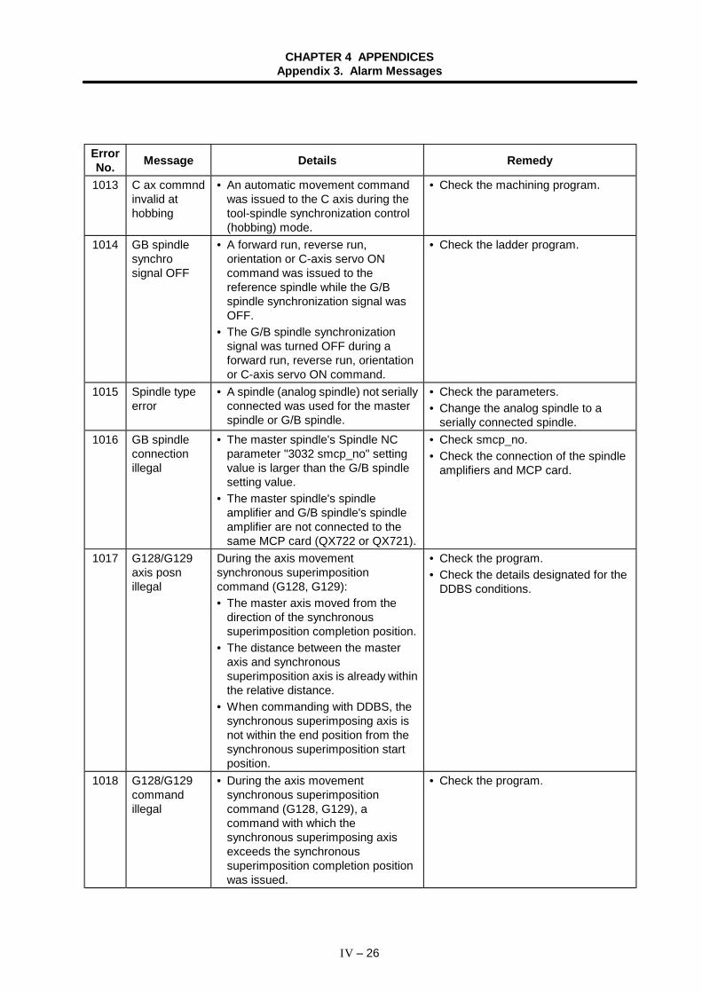
CHAPTER 4 APPENDICESAppendix 3. Alarm Messages
IV – 26
ErrorNo. Message Details Remedy
1013 C ax commndinvalid athobbing
• An automatic movement commandwas issued to the C axis during thetool-spindle synchronization control(hobbing) mode.
• Check the machining program.
1014 GB spindlesynchrosignal OFF
• A forward run, reverse run,orientation or C-axis servo ONcommand was issued to thereference spindle while the G/Bspindle synchronization signal wasOFF.
• The G/B spindle synchronizationsignal was turned OFF during aforward run, reverse run, orientationor C-axis servo ON command.
• Check the ladder program.
1015 Spindle typeerror
• A spindle (analog spindle) not seriallyconnected was used for the masterspindle or G/B spindle.
• Check the parameters.• Change the analog spindle to a
serially connected spindle.1016 GB spindle
connectionillegal
• The master spindle's Spindle NCparameter "3032 smcp_no" settingvalue is larger than the G/B spindlesetting value.
• The master spindle's spindleamplifier and G/B spindle's spindleamplifier are not connected to thesame MCP card (QX722 or QX721).
• Check smcp_no.• Check the connection of the spindle
amplifiers and MCP card.
1017 G128/G129axis posnillegal
During the axis movementsynchronous superimpositioncommand (G128, G129):• The master axis moved from the
direction of the synchronoussuperimposition completion position.
• The distance between the masteraxis and synchronoussuperimposition axis is already withinthe relative distance.
• When commanding with DDBS, thesynchronous superimposing axis isnot within the end position from thesynchronous superimposition startposition.
• Check the program.• Check the details designated for the
DDBS conditions.
1018 G128/G129commandillegal
• During the axis movementsynchronous superimpositioncommand (G128, G129), acommand with which thesynchronous superimposing axisexceeds the synchronoussuperimposition completion positionwas issued.
• Check the program.
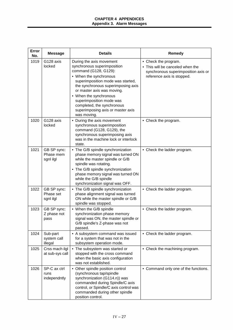
CHAPTER 4 APPENDICESAppendix 3. Alarm Messages
IV – 27
ErrorNo. Message Details Remedy
1019 G128 axislocked
During the axis movementsynchronous superimpositioncommand (G128, G129):• When the synchronous
superimposition mode was started,the synchronous superimposing axisor master axis was moving.
• When the synchronoussuperimposition mode wascompleted, the synchronoussuperimposing axis or master axiswas moving.
• Check the program.• This will be canceled when the
synchronous superimposition axis orreference axis is stopped.
1020 G128 axislocked
• During the axis movementsynchronous superimpositioncommand (G128, G129), thesynchronous superimposing axiswas in the machine lock or interlockstate.
• Check the program.
1021 GB SP sync:Phase memsgnl ilgl
• The G/B spindle synchronizationphase memory signal was turned ONwhile the master spindle or G/Bspindle was rotating.
• The G/B spindle synchronizationphase memory signal was turned ONwhile the G/B spindlesynchronization signal was OFF.
• Check the ladder program.
1022 GB SP sync:Phase setsgnl ilgl
• The G/B spindle synchronizationphase alignment signal was turnedON while the master spindle or G/Bspindle was stopped.
• Check the ladder program.
1023 GB SP sync:Z phase notpass
• When the G/B spindlesynchronization phase memorysignal was ON, the master spindle orG/B spindle's Z-phase was notpassed.
• Check the ladder program.
1024 Sub-partsystem callillegal
• A subsystem command was issuedfor a system that was not in thesubsystem operation mode.
• Check the ladder program.
1025 Crss mach ilglat sub-sys call
• The subsystem was started orstopped with the cross commandwhen the basic axis configurationwas not established.
• Check the machining program.
1026 SP-C ax ctrlrunsindependntly
• Other spindle position control(synchronous tap/spindlesynchronization (G114.n)) wascommanded during Spindle/C axiscontrol, or Spindle/C axis control wascommanded during other spindleposition control.
• Command only one of the functions.
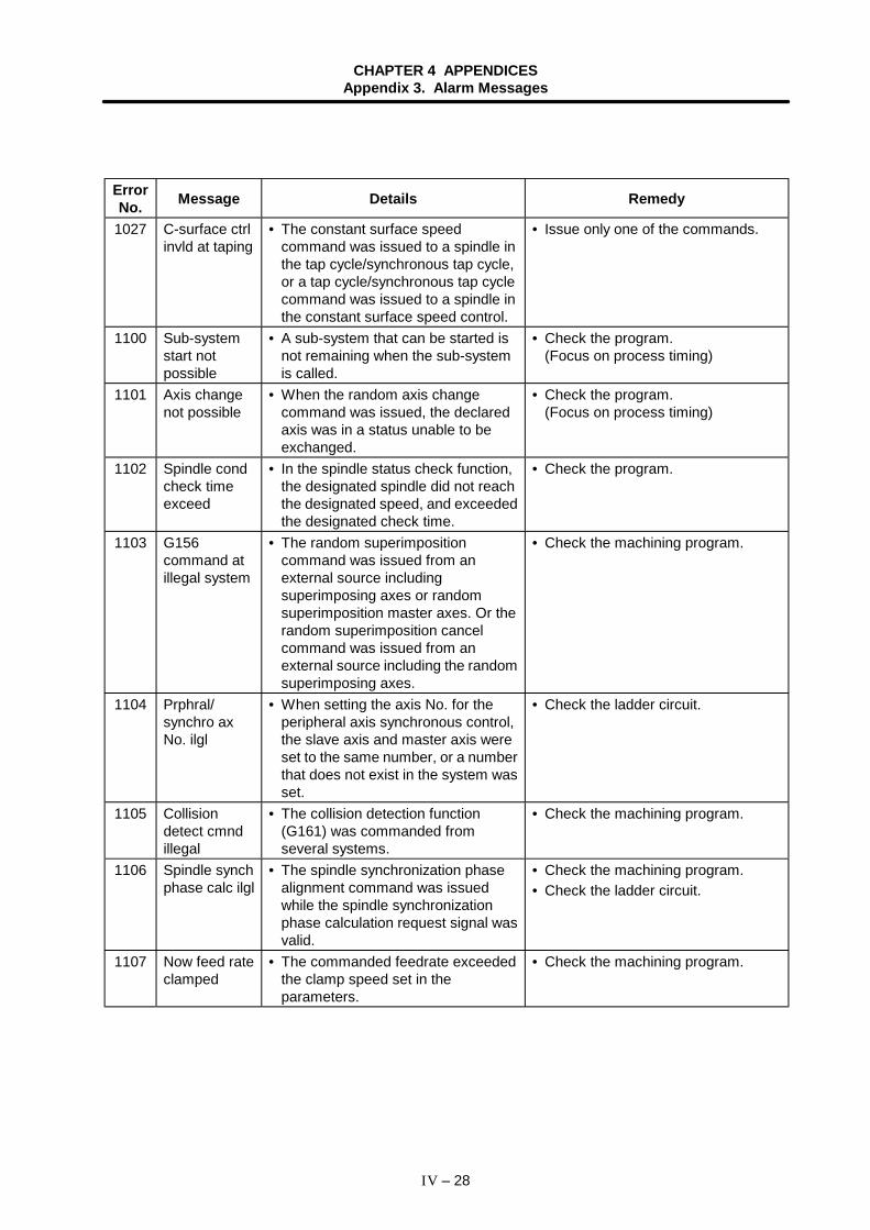
CHAPTER 4 APPENDICESAppendix 3. Alarm Messages
IV – 28
ErrorNo. Message Details Remedy
1027 C-surface ctrlinvld at taping
• The constant surface speedcommand was issued to a spindle inthe tap cycle/synchronous tap cycle,or a tap cycle/synchronous tap cyclecommand was issued to a spindle inthe constant surface speed control.
• Issue only one of the commands.
1100 Sub-systemstart notpossible
• A sub-system that can be started isnot remaining when the sub-systemis called.
• Check the program.(Focus on process timing)
1101 Axis changenot possible
• When the random axis changecommand was issued, the declaredaxis was in a status unable to beexchanged.
• Check the program.(Focus on process timing)
1102 Spindle condcheck timeexceed
• In the spindle status check function,the designated spindle did not reachthe designated speed, and exceededthe designated check time.
• Check the program.
1103 G156command atillegal system
• The random superimpositioncommand was issued from anexternal source includingsuperimposing axes or randomsuperimposition master axes. Or therandom superimposition cancelcommand was issued from anexternal source including the randomsuperimposing axes.
• Check the machining program.
1104 Prphral/synchro axNo. ilgl
• When setting the axis No. for theperipheral axis synchronous control,the slave axis and master axis wereset to the same number, or a numberthat does not exist in the system wasset.
• Check the ladder circuit.
1105 Collisiondetect cmndillegal
• The collision detection function(G161) was commanded fromseveral systems.
• Check the machining program.
1106 Spindle synchphase calc ilgl
• The spindle synchronization phasealignment command was issuedwhile the spindle synchronizationphase calculation request signal wasvalid.
• Check the machining program.• Check the ladder circuit.
1107 Now feed rateclamped
• The commanded feedrate exceededthe clamp speed set in theparameters.
• Check the machining program.
CHAPTER 4 APPENDICESAppendix 3. Alarm Messages
IV – 29
ErrorNo. Message Details Remedy
1108 SP clampedatsuperimposetap
• When a tap cycle or synchronous tapcycle was commanded to asuperimposing axis, the actualrotation speed of the superimposingspindle exceeded the spindle clampspeed.
• The synchronous tap cycle wascommanded when a rotationcommand was not input for themaster spindle or superimposingspindle.
• Check the program.
1109 Base SP C-surface invldat tap
• A constant surface speed commandwas issued to the master spindlewhen the tap cycle or synchronoustap cycle was being executed withthe superimposing spindle.
• During constant surface speedcontrol of the master spindle, the tapcycle or synchronous tap cyclecommand was issued to thesuperimposing spindle.
• Check the program.
1110 Ax exchangenot possible
• A random axis exchange commandfor which axis exchange is notpossible or a random axis exchangereturn command was issued.
• Check the program.
1111 Now axdetached orservo off
• The movement command followingthe random axis superimpositioncommand, a movement commandfollowing the superimposition/synchronization control, or amovement command following theperipheral axis synchronizationcontrol was issued during the axisremoval mode or during servo OFF.
• Check the program.
1112 Mirror imagecommandillegal
• The mirror image was turned ON fora superimposition/synchronous axisor milling control axis.
• The external mirror image andparameter mirror image were turnedON simultaneously.
• Check the mirror image signal in thePLC Interface.
• Check the Axis parameter mirrorimage.
• Check the program.
1113 T-leng measax not retn(TLM2)
• Measurement of an axis that had notreturned to the zero point wasattempted during manual tool lengthmeasurement 2.
• Carry out zero point return beforemeasuring.
1114 Tool No. notfound (TLM2)
• The designated tool number was notwithin the number of tool sets duringmanual tool length measurement 2.
• Designate a tool number within thenumber of tool sets.
CHAPTER 4 APPENDICESAppendix 3. Alarm Messages
IV – 30
ErrorNo. Message Details Remedy
1115 Compen axillegal (TLM2)
• Measurement of two or more axeswas attempted simultaneouslyduring manual tool lengthmeasurement 2.
• The measured axis was not the toolcompensation target axis.
• Check the axis to be measured.
1116 Sensor No.not specified(TLM2)
• Measurement without designatingthe sensor No. was attempted duringmanual tool length measurement 2.
• Confirm the sensor No. designatedfor the parameter manual tool lengthmeasurement 2.
1117 Inclined ctrlmanual modeilgl
• Automatic dogless, manual zeropoint return, manual feed or amanual mode other than handle wasselected in the actual axis mode.
• Incremental feed, manual skip orautomatic dogless was selectedduring the orthogonal mode.
• Automatic handle interruption wasselected during manual-automaticsimultaneous operation.
• Check the ladder circuit.
1118 G170/G171cood notchanged
• The G170/G171 coordinatechangeover command was issuedduring start point designation wait,end point designation wait,miscellaneous function output duringaxis movement wait, or duringsuperimposition/synchronous/peripheral axis synchronous control.
• Check the machining program.
1119 Inclined ctrlaxis illegal
• A cross command, random axisexchange command orsuperimposition/synchronous/peripheral axis synchronous controlcommand was issued to an inclinedmaster axis or inclined axis.
• A synchronous tap command tapaxis was commanded for an inclinedaxis.
• Check the machining program.
9097 Positionsupervisingerror 3
• The difference of the previous cycle'sfeedback position and the currentcycle's feedback position exceededthe tolerable range.
• A positional deviation occurred.
• Contact the Service Center.
9098 Positionsupervisingerror 1
• The data for the program analysisprocess and interpolation processdid not match, causing a positionaldeviation.
• A positional deviation occurred.
• Contact the Service Center.
9099 Positionsupervisingerror 2
• The data for the interpolationprocess and acceleration/deceleration process did not match,causing a positional deviation.
• A positional deviation occurred.
• Contact the Service Center.
CHAPTER 4 APPENDICESAppendix 3. Alarm Messages
IV – 31
3.1.2 Absolute position return again (M02)
M02 Abs posn return required again
Details RemedyThe operation mode was changed to the zeropoint return mode while in the retract returnmode.
• Select an operation mode other than the zero pointreturn mode.
3.1.3 Interference check alarm (M03)
M03 Interfere alarm (command)
Details RemedyThe issued command caused an interferencebetween two devices such as tool turrets.
• Release the alarm by a reset operation.• To move the interfering device further in the
interfering direction, invalidate an interference checkbefore doing it.
• Refer to the instruction manual issued by the machinemanufacturer for the procedure to invalidate aninterference check.
3.1.4 Interference area alarm (M04)
M04 Interfere alarm (present area)
Details RemedyTwo interfering devices such as tool turretsentered an interference area.
• Invalidate an interference check, and then move thedevices.
• Refer to the instruction manual issued by the machinemanufacturer for the procedure to invalidate aninterference check.
CHAPTER 4 APPENDICESAppendix 3. Alarm Messages
IV – 32
3.2 Stop Codes (T )
This code indicates that the NC has stopped for some reason.
T01 Message In this status, automatic operation start cannot be executed when anattempt is made to execute it from the NC stop status.The numbers given in the table can be referred to on the Alarm listscreen (Diagnosis group).
ErrorNo. Message Details Remedy
0101 Axis in motion • Since one of the axes is in motion,automatic start is not possible.
• Try automatic start again after allaxes have stopped.
0102 NC not ready • Automatic start is not possiblebecause the NC ready signal is notsupplied.
• Another alarm has been issued andthe cause should be checked out andremedy.
0103 Reset signalON
• Automatic start is not possiblebecause the reset signal has beeninput.
• Set the reset input signal to "OFF".• Check for a failure in the reset
switch.• Check the sequence program.
0104 Autooperationpause signalON
• The "FEED HOLD" switch on themachine operation panel is ON(valid).
• Check the "FEED HOLD" switch.(B contact)
• Check for a breakage in the feedhold signal wire.
• Check the sequence program.0105 H/W stroke
end axisexists
• Automatic start is not possiblebecause one of the axes hasreached the stroke end.
• If the stroke end has been reachedby the axis end, move the axis byoperating it manually.
• Check for a breakage in the strokeend signal wire.
• Check for a failure in the stroke endlimit switch.
0106 S/W strok endaxis exists
• Automatic start is not possiblebecause one of the axes hasreached the stored stroke limit.
• Move the axis manually.• Check the contents of the parameter
unless the axis end is at the storedstroke end.
0107 No operationmode
• The operation mode has not beenselected.
• Restart after selecting the operationmode.
• Check for a breakage in theautomatic operation mode (memory,MDI) signal wire.
0108 Operationmodeduplicated
• Two or more operation modes havebeen selected in error.
• Check for a shortcircuit in the modeselection signal wire (memory, MDI).
• Check for a failure in the switch.• Check the sequence program.• Restart after selecting the operation
mode.0109 Operation
modechanged
• A shift was made from one automaticoperation mode to another automaticoperation mode.
• Return to the original automaticoperation mode, and then restart.
0110 In buffercorrection
• Start is impossible because buffer isbeing corrected.
• Bring the buffer correction to an end.Or cancel it and then restart.
CHAPTER 4 APPENDICESAppendix 3. Alarm Messages
IV – 33
ErrorNo. Message Details Remedy
0114 Fixed cycleregisteredillegal
• The fixed cycle subprogram is notcorrectly registered.
• Register the fixed cycle subprogramagain.
• Refer to "Appendix 1. Fixed CycleProgram" for the procedures.
0115 CNCoverheat
• NC operation cannot be startedbecause of a thermal warning (Z53CNC overheat).
• The temperature of the NC oroperation board has risen above thespecified temperature. Take coolingmeasures. Turn OFF the NC power,or lower the temperature with acooler, etc.
0116 Stat sgnl ONin sub-sysmode
• An automatic start signal was inputfor a system in the sub-systemoperation mode before thesubsystem was started.
• Check the program.• Check the user PLC.
0138 In absoluteposition alarm
• A start signal was input during anabsolute position detection alarm.
• Start after the absolute positiondetection alarm is released.
0139 In abs posninitial setting
• Start signal is input during zero pointinitialization of absolute positiondetection system.
• Start after the zero point initializationis complete.
0151 In prog checkbackwardmode
• Automatic start is disabled becausethe program check function is inbackward state.
• Put the program check function inforward state and execute automaticstart.
0160 Memorycapacity over
• The super option is invalid. Theprogram memory capacity of themachining program has beenexceeded.
• Delete or format the machiningprogram.
• Add the super option purchase point.
T02 Message The feed hold status has been established due to some condition orother during automatic operation.The numbers given in the table can be referred to on the Alarm listscreen (Diagnosis group).
ErrorNo. Message Details Remedy
0201 H/W strokeend axisexists
• An axis has reached the storedstroke limit.
• Using manual operations, move theaxis from the stroke end limit switch.
• The machining program must becorrected.
0202 S/W strokeend axisexists
• An axis has reached the storedstroke limit.
• Using manual operations, move theaxis from the stroke end limit switch.
• The machining program must becorrected.
0203 Reset signalON
• The reset signal has been input. • The position at which the program isexecuted has returned to the headand so automatic operation isperformed from the start point of themachining program.
0204 Autooperationpause signalON
• The "FEED HOLD" switch on themachine operation board is ON(valid).
• Automatic operation can be resumedby operating the CYCLE STARTswitch.
CHAPTER 4 APPENDICESAppendix 3. Alarm Messages
IV – 34
ErrorNo. Message Details Remedy
0205 Operationmodechanged
• The mode changed from theautomatic operation mode to anotherautomatic operation mode.
• Return to the original automaticoperation mode, and then restart.
0206 Ininterferencemode
• A command where two objects (toolturrets, etc.) will interfere has beenissued.
• Two objects (tool turrets, etc.) haveentered the buffer area.
• Release the alarm with reset.• To move the interfering object in the
interfering direction, invalidate theinterference check first.
• Refer to the instruction manualissued by the machine manufacturerfor how to invalidate the interferencecheck.
0215 Abs posndetect alarmoccurred
• Absolute position detection alarmoccurred.
• Release the absolute positiondetection alarm.
T03 Message Operation stops after a single block in the program has executedduring automatic operation.The numbers given in the table can be referred to on the Alarm listscreen (Diagnosis group).
ErrorNo. Message Details Remedy
0301 Single blockstop signalON
• Block stop occurred because the"SINGLE BLOCK STOP" switch onthe machine operation panel wasON.
• Automatic operation can be resumedby setting the CYCLE START switchto ON.
0302 Block stopcmnd in usermacro
• The block stop command wasspecified in user macro program.
• Automatic operation can be resumedby setting the CYCLE START switchto ON.
0303 Operationmodechanged
• The mode changed from theautomatic operation mode to anotherautomatic operation mode.
• First return to the original automaticmode and automatic operation canbe resumed by setting the CYCLESTART switch to ON.
0304 MDI interruptcompleted
• The last block of MDI completed.• The last block of PLC interrupt
completed.
• MDI operation can be resumed bysetting MDI again and setting theCYCLE START switch to ON.
• Turn the CYCLE START switch toON to restart automatic operation.
0305 Teachingblockcompleted
• The block of the position controlcommand (G132) or position controlvariable skip command (G133)completed during teaching mode.
• Turn the CYCLE START switch toON to restart automatic operation.
T04 Message Collation and stop occurred during automatic operation.
ErrorNo. Message Details Remedy
0401 Collation andstop
• Collation and stop occurred. • Automatic operation can be resumedby automatically starting.
CHAPTER 4 APPENDICESAppendix 3. Alarm Messages
IV – 35
3.3 Messages related to servo
These alarms pertain to errors in the servo system, such as the servo drive amplifier, motor and encoder.The alarm message, status No. and axis address are displayed on the Alarm message screen.If an S command name is displayed instead of the axis address, this is an alarm from the spindle side.Refer to "3.4 Messages related to spindle".Refer to the MELDAS AC Servo/Spindle Specifications (BNP-B3759) for details.
3.3.1 Servo alarms (S )
The method of resetting the servo alarm differs according to the alarm message No. (SOO).
No. Resetting method ReferenceS01 The alarm can be reset by turning the NC power ON again
after removing the cause of the alarm.(1) Servo alarms
S02 Review the parameters. (2) Initial parameter errorS03 This appears when there is an error in the servo system.
The alarm can be reset by inputting the NC reset key afterremoving the cause of the alarm.
S04 This appears when there is an error in the servo system.The alarm can be reset by turning the servo drive unitpower ON again after removing the cause of the alarm.
(1) Servo alarms
Caution
! If an alarm occurs, remove the cause, and confirm that the operation signal is not being input.Then secure the safety and reset the alarm before restarting operation.
CHAPTER 4 APPENDICESAppendix 3. Alarm Messages
IV – 36
(1) Servo alarms
S Message Status Axis name
(Note) If an S command name is displayed instead of an axis name,refer to Section "3.4.1 Spindle alarms".
The applicable models shown in thetable are as follow: V1/V2 : MDS-B-V1/V2 SVJ2 : MDS-B-SVJ2 ISV : HS Series
Applicable modelsSta-tus Abbrev. Message Details
V1/V2 SVJ2 ISV
10 UV Under voltage The PN bus voltage is 200V or less.11 ASE Axis selection error The setting of the axis setting rotary switches on
the 2-axis integrated drive unit is illegal.12 ME Memory error 1 The memory IC (SRAM or FLROM) check sum is
illegal.13 SWE S/W processing
errorS/W data processing did not end within thespecified time. (Including peripheral G/A errors.)
15 ME2 Memory error 2 An error was detected with the amplifier's self-diagnosis.
16 RD1 Magnetic poleposn detect err1
The differential input for one of the magnetic poleposition detection signal U, V or W phases of theOHE-type detector has become "H" or "L".
17 ADE AD converter error The A/D convertor for current detection did notwork correctly at initialization.
18 WAT Initialcommunicationerror
Correct communication of the absolute position ormagnetic pole position data is not possible with theOHA-type detector or serial pulse encoder.
1A WATS Encoder:Init commu error(SUB)
Initial communication with the detector was notpossible with the system that uses the OHA25K-ET machine end detector.
1B SCPUS Encoder:CPU error (SUB)
An error was detected in the data stored in theEEROM with the high-speed serial detectorconnected to the machine end.
1C SLEDS Encoder:LED error (SUB)
LED deterioration was detected with the high-speed serial detector connected to the machineend.
1D SDATS Encoder:Data error (SUB)
An error was detected in the position per rotationwith the high-speed serial detector connected tothe machine end.
1E SOHE Encoder:Thermal error(SUB)
The thermal protector built into the detectoractivated with the high-speed serial detectorconnected to the machine end.
1F STRES Encoder:Commu error(SUB)
Communication with the detector was cut off withthe high-speed serial detector connected to themachine end.
20 NS1 No signal detected1
The differential input for one of the A, B or Z phasesignals of the detector installed on the motor endhas become "H" or "L".(Software detection in the B Series.)
21 NS2 No signal detected2
The differential input for one of the A, B or Z phasesignals of the detector installed on the machineend has become "H" or "L".(Software detection in the B Series.)
CHAPTER 4 APPENDICESAppendix 3. Alarm Messages
IV – 37
Applicable modelsSta-tus Abbrev. Message Details
V1/V2 SVJ2 ISV22 LSIE LSI error An error occurred in the LSI operation.24 PG Ground fault A motor cable ground fault was detected.25 ABSE Absolute position
lostThe absolute position data in the absolute positiondetector was lost.
26 NAE Unused axis error A power module error occurred in an axis for whichthe axis setting rotary switch on the 2-axisintegrated drive unit was set to "F" to exclude fromcontrol.
27 SCCPU Abs posn detectscale CPU err
The CPU in the absolute position detection linearscale is not operating correctly.
28 SOSP Absolute positionoverspeed
The scale in the absolute position linear scalemoved at a speed equal to or higher than 45mm/sduring initialization.(Alarm output from inside the linear scale.)
29 SABS Abs posn encodercircuit err
A hardware error occurred in the absolute positiondetection circuit in the absolute position linearscale.(Alarm output from inside the linear scale.)
2A SINC Inc posn encodercircuit err
A hardware error occurred in the relative positiondetection circuit in the relative position linear scale.(Alarm output from inside the linear scale.)
2B SCPU Encoder:Scale CPU error
An error occurred in the CPU in the serial encoderinstalled on the motor end.(Alarm output from the detector.)
2C SLED Encoder:LED error
Deterioration of the LED in the detector wasdetected.
2D SDAT Encoder:Data error
An error was detected in the position per rotation inthe detector.
2F STRE Encoder:Commu error
Communication with the detector was cut off, orthe communication data was abnormal.
30 OR Over regeneration Overheating of the regenerative resistor wasdetected.
31 OS Overspeed The motor speed reached 1.2 times the ratedmotor speed.
32 PMOC Power moduleovercurrent
An overcurrent was detected in the IPM used inthe servo drive main circuit section.
33 OV Overvoltage The PN bus voltage is more than 400V.34 DP CRC error (NC) A CRC error occurred in the communication data
from the NC.35 DE Data error (NC) The movement command data from the NC is
abnormally large.36 TE Transferring error
(NC)The periodic data transfer from the NC wasinterrupted.
37 PE Initial parametererror
There is an error in the Servo parameterstransferred from the NC during servo driveinitialization.
38 TP1 Protocol error 1(frame)
There is an error in the communication protocolwith the NC.(Frame error)
CHAPTER 4 APPENDICESAppendix 3. Alarm Messages
IV – 38
Applicable modelsSta-tus Abbrev. Message Details
V1/V2 SVJ2 ISV39 TP2 Protocol error 2
(information)There is an error in the communication protocolwith the NC.(Information error)
3A OC Overcurrent An excessive current flowed in the motor.3B PMOH Power module
overheatOverheating of the IPM used in the inverter wasdetected.
3C RCE Regenerativecircuit error
An error was detected in the regenerativetransistor or resistor.Overheating of the power module was detected inthe SVJ-10, 20.
42 FE1 Feedback error1(semi-closed)
1. A detector feedback signal pulse was omittedin the OHE-type/OHA-type detector used in asemi-closed loop system and ball screw endclosed loop system.
2. A detector feedback signal pulse was omittedin the low-speed serial-type absolute positionlinear scale.
43 FE2 Feedback error2(full-closed)
A deviation was detected in the motor end detectorand machine end detector feedback amounts in aclosed loop system.
46 OHM Motor overheat The motor or detector thermal protector activated.4F IPS Instantaneous stop The control power was disconnected for 50ms or
more.50 OL1 Overload 1 The motor was operated with the motor current in
the overload range set in the overload detectionlevel (parameter OLL) and overload time constant(parameter OLT). (Note 1)
51 OL2 Overload 2 A current command of 95% or more of the max.output current continued for 1 second or more.
52 OD1 Excessive error(SV ON)
When the servo was turned ON, the actualposition in respect to the command exceeded theexcessive error width 1 value (parameter OD1).
53 OD2 Excessive error(SV OFF)
When the servo was turned OFF, the actualposition in respect to the command exceeded theexcessive error width 2 value (parameter OD2).
54 OD3 Excessive error 3 When the servo was turned OFF, the actualposition in respect to the command exceeded theexcessive error width 3 value (parameter OD3).
55 EM Externalemergency stoperror
After the external emergency stop was input, thecontactor cutoff command was not issued evenafter 30 seconds passed.(This alarm is detected even when removing thecontrol axis.)
58 CLT1 Collision detection0
During the G0 modal (rapid traverse), the collisiondetection method 1 error was detected.
59 CLT2 Collision detection1
During the G1 modal (cutting feed), the collisiondetection method 1 error was detected.
5A CLT3 Collision detection2
The collision detection method 2 error wasdetected.
CHAPTER 4 APPENDICESAppendix 3. Alarm Messages
IV – 39
Applicable modelsSta-tus Abbrev. Message Details
V1/V2 SVJ2 ISV
5F MCE Contactor fusing The external contactor contact was fused.61 POC Pwr sply
regenerateovercurent
An overcurrent (Ic) was detected in the powermodule (IPM).
63 PARE Pwr sply auxiregeneration err
The auxiliary regeneration transistor remainedON.
65 PRAE Pwr sply rush relayerror
The rush resistance short-circuit relay is not ON.
67 PPHL Pwr sply phaseerror detected
The input power (R, S, T) has an open phase.
68 PWD Pwr sply watch dog The power supply software processing failed tofinish within the specified time.
69 PPNG Pwr sply groundingdetection
A ground fault was detected in the motor.This is only detected during READY ON.
6A Pwr sply ext contctfusion det
The external contactor was turned ON in spite ofthe READY OFF status.
6B Pwr sply rush relaydet
The rush resistance short-circuit relay is still ON.
6C PCHE Pwr sply maincircuit error
The main circuit condenser is not correctlycharged.
6E PME Pwr sply memoryerror
An error occurred in the memory circuit section.
6F PADE Pwr sply AD error An error was detected in the A/D converter sectionor power supply.
71 PINL Pwr splymomentary faildetect
The external contactor was turned OFF in spite ofthe READY ON status. Or, an instantaneouspower failure of 55ms or more occurred.
73 J Pwr sply overregeneration
The regenerative capacity limit of the power supplywas exceeded. (Note 2)
74 K Pwr splyregenerateresistanceoverheat
Regenerative resistor overheating occurred.
75 POV Pwr splyovervoltage
The voltage between L+ and L− exceeded 410V.
76 Pwr sply EMG stopsetting err
The rotary switch setting and parameter (PTYP)setting do not match.
77 N Pwr sply powermodule overheat
Overheating of the power module (IPM) wasdetected.
88 WD Watch dog The servo amplifier software processing failed tofinish within the specified time.
(Note 1) The alarm "50" cannot be reset until the load drops to below the resetting level.(Note 2) To prevent operation from restarting immediately from the over-regeneration state, alarm "73"
cannot be reset after occurring until the control power (L11, L21) continuity state has continuedfor 15 minutes or more.Even if the NC power or control power is turned ON again immediately after the alarm hasoccurred, the alarm cannot be reset.If the power is turned ON again immediately after the alarm has occurred, maintain thecontinuity state for 15 minutes or more, and then turn the power ON again.
CHAPTER 4 APPENDICESAppendix 3. Alarm Messages
IV – 40
(2) Initial parameter error
S02 Initial parameter error Parameter number Axis name
(Note) If an S command name is displayed instead of the axisname, refer to "3.4.1 Spindle alarms".
An error was found in theparameters sent from the NC sideto the servo amplifier side after theNC power was turned ON.The parameter No. and axis namefor which an alarm occurred willappear.
Parameter No. Details Remedy1 to 64 An error was found in the Servo parameters
sent from the NC during initialization.Refer to the instruction manual for theservomotor being used.
3.3.2 Servo warnings (s )
(1) s51 Initial parameter error
s51 Parameter error Parameter number Axis name
(Note) If an S command name is displayed instead of theaxis name, refer to "3.4.2 Spindle warnings".
This error is reset when the parameter ischecked and set to the correct value. Illegalparameters are ignored, and if an illegalparameter is set, the previous value will beheld. (The servo will not turn OFF.)The parameter No. and axis name for whicha warning occurred will appear.
Parameter No. Details Remedy1 to 48, 69, 71,101 to 106, 108
The Servo parameter setting data is illegal. Refer to the details on the servo warningalarms.
(2) s52 Servo warning
s52 Message Warning No. Axis name
(Note) If an S command name is displayed instead of theaxis name, refer to "3.4.2 Spindle warnings".
The servo warning is displayed.The parameter No. and axis name for whichan alarm occurred will appear.The applicable models shown in the tableare as follows: V1/V2 : MDS-B-V1/V2 SVJ2 : MDS-B-SVJ2 ISV : HS Series
Applicable modelsWarningNo. Abbrev. Message Details
V1/V2 SVJ2 ISV
90 WST L-speed serial inicommu err
Initial communication with the absolute positionlinear scale was not possible.
91 WAS L-speed serialcommu error
An error in the communication with the detectorwas detected in the absolute position detectionsystem using the OHA25K/OHA25K-ET/absoluteposition linear scale.
92 WAF L-speed serialprotocol error
An error was detected in the data from the detectorin an absolute position detection system using theOHA25K/OHA25K-ET/absolute position linearscale.
93 WAM Absolute positiondislocation
When the NC power was turned ON, the absoluteposition counter could not be set becauseabsolute position data had been varied.
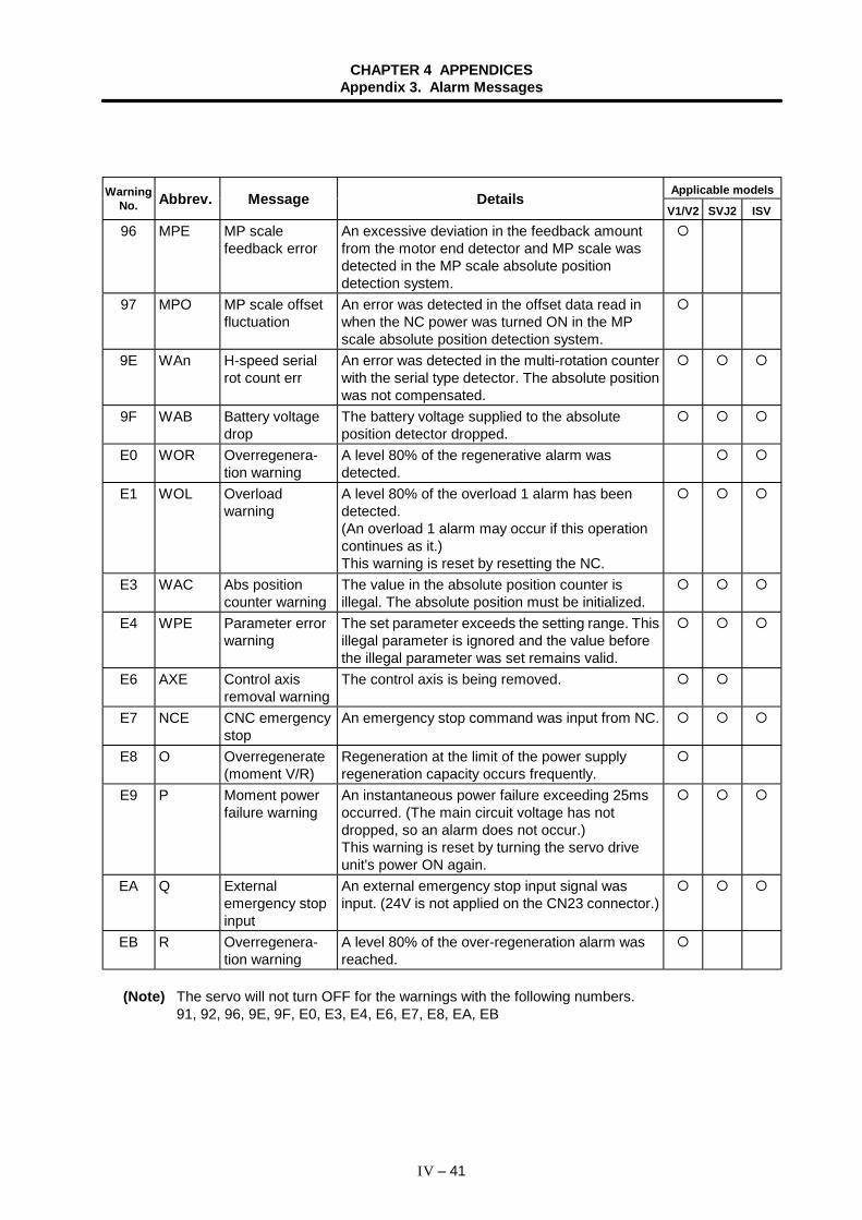
CHAPTER 4 APPENDICESAppendix 3. Alarm Messages
IV – 41
Applicable modelsWarningNo. Abbrev. Message Details
V1/V2 SVJ2 ISV
96 MPE MP scalefeedback error
An excessive deviation in the feedback amountfrom the motor end detector and MP scale wasdetected in the MP scale absolute positiondetection system.
97 MPO MP scale offsetfluctuation
An error was detected in the offset data read inwhen the NC power was turned ON in the MPscale absolute position detection system.
9E WAn H-speed serialrot count err
An error was detected in the multi-rotation counterwith the serial type detector. The absolute positionwas not compensated.
9F WAB Battery voltagedrop
The battery voltage supplied to the absoluteposition detector dropped.
E0 WOR Overregenera-tion warning
A level 80% of the regenerative alarm wasdetected.
E1 WOL Overloadwarning
A level 80% of the overload 1 alarm has beendetected.(An overload 1 alarm may occur if this operationcontinues as it.)This warning is reset by resetting the NC.
E3 WAC Abs positioncounter warning
The value in the absolute position counter isillegal. The absolute position must be initialized.
E4 WPE Parameter errorwarning
The set parameter exceeds the setting range. Thisillegal parameter is ignored and the value beforethe illegal parameter was set remains valid.
E6 AXE Control axisremoval warning
The control axis is being removed.
E7 NCE CNC emergencystop
An emergency stop command was input from NC.
E8 O Overregenerate(moment V/R)
Regeneration at the limit of the power supplyregeneration capacity occurs frequently.
E9 P Moment powerfailure warning
An instantaneous power failure exceeding 25msoccurred. (The main circuit voltage has notdropped, so an alarm does not occur.)This warning is reset by turning the servo driveunit's power ON again.
EA Q Externalemergency stopinput
An external emergency stop input signal wasinput. (24V is not applied on the CN23 connector.)
EB R Overregenera-tion warning
A level 80% of the over-regeneration alarm wasreached.
(Note) The servo will not turn OFF for the warnings with the following numbers.91, 92, 96, 9E, 9F, E0, E3, E4, E6, E7, E8, EA, EB
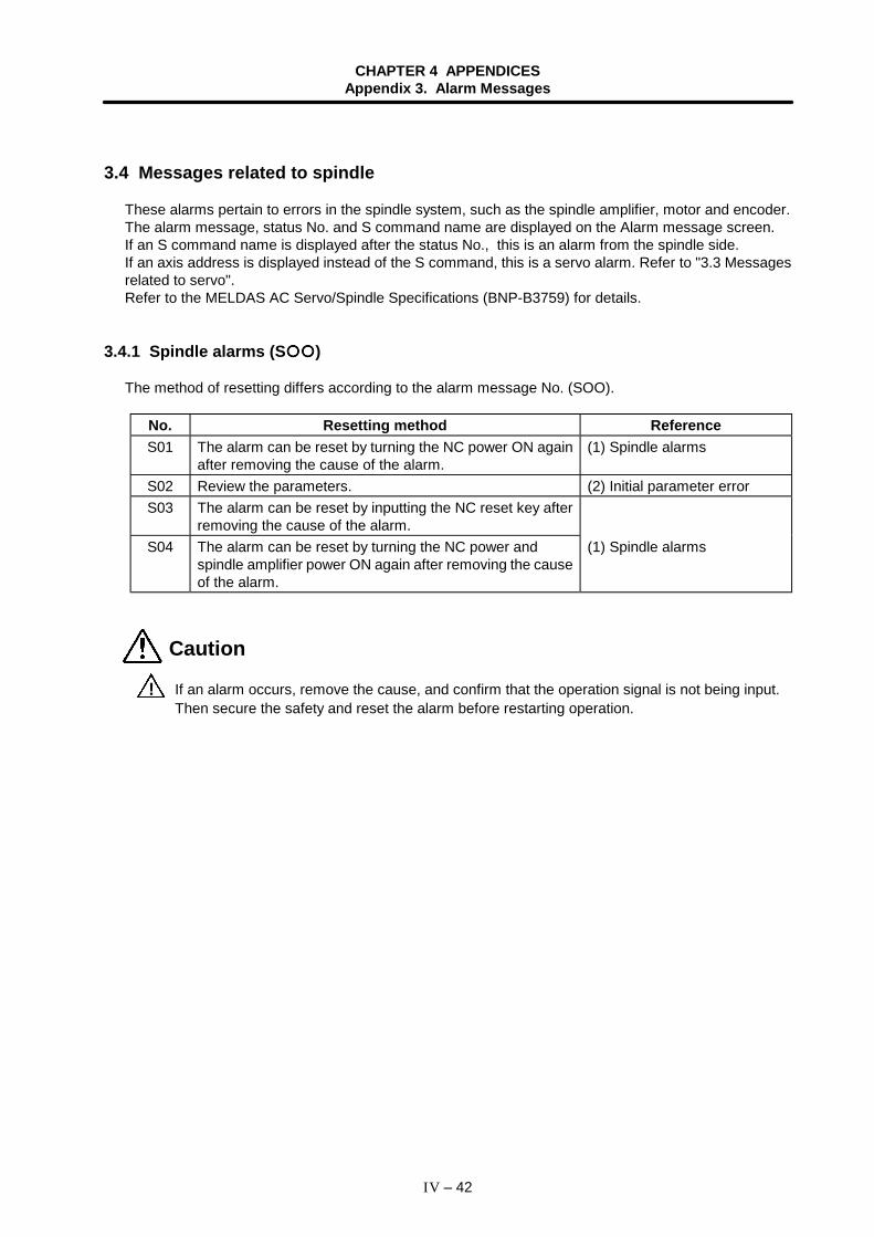
CHAPTER 4 APPENDICESAppendix 3. Alarm Messages
IV – 42
3.4 Messages related to spindle
These alarms pertain to errors in the spindle system, such as the spindle amplifier, motor and encoder.The alarm message, status No. and S command name are displayed on the Alarm message screen.If an S command name is displayed after the status No., this is an alarm from the spindle side.If an axis address is displayed instead of the S command, this is a servo alarm. Refer to "3.3 Messagesrelated to servo".Refer to the MELDAS AC Servo/Spindle Specifications (BNP-B3759) for details.
3.4.1 Spindle alarms (S )
The method of resetting differs according to the alarm message No. (SOO).
No. Resetting method ReferenceS01 The alarm can be reset by turning the NC power ON again
after removing the cause of the alarm.(1) Spindle alarms
S02 Review the parameters. (2) Initial parameter errorS03 The alarm can be reset by inputting the NC reset key after
removing the cause of the alarm.S04 The alarm can be reset by turning the NC power and
spindle amplifier power ON again after removing the causeof the alarm.
(1) Spindle alarms
Caution
! If an alarm occurs, remove the cause, and confirm that the operation signal is not being input.Then secure the safety and reset the alarm before restarting operation.
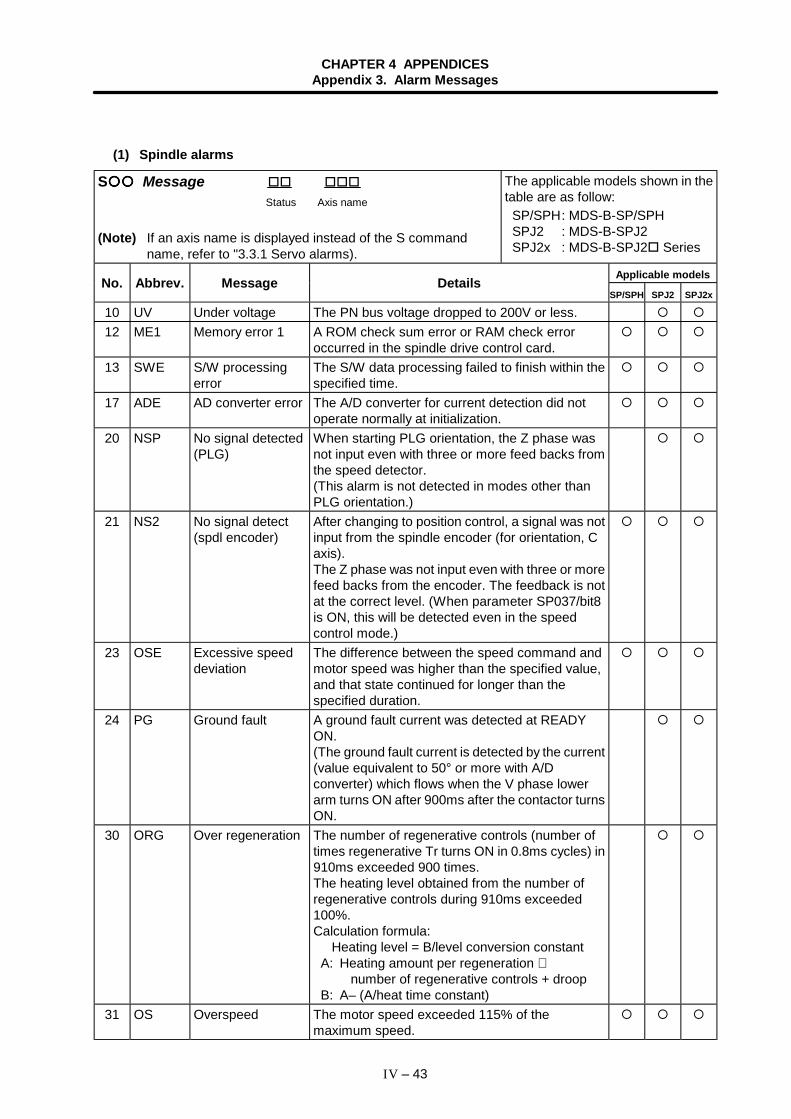
CHAPTER 4 APPENDICESAppendix 3. Alarm Messages
IV – 43
(1) Spindle alarms
S Message Status Axis name
(Note) If an axis name is displayed instead of the S commandname, refer to "3.3.1 Servo alarms).
The applicable models shown in thetable are as follow: SP/SPH: MDS-B-SP/SPH SPJ2 : MDS-B-SPJ2 SPJ2x : MDS-B-SPJ2 Series
Applicable modelsNo. Abbrev. Message DetailsSP/SPH SPJ2 SPJ2x
10 UV Under voltage The PN bus voltage dropped to 200V or less.12 ME1 Memory error 1 A ROM check sum error or RAM check error
occurred in the spindle drive control card.13 SWE S/W processing
errorThe S/W data processing failed to finish within thespecified time.
17 ADE AD converter error The A/D converter for current detection did notoperate normally at initialization.
20 NSP No signal detected(PLG)
When starting PLG orientation, the Z phase wasnot input even with three or more feed backs fromthe speed detector.(This alarm is not detected in modes other thanPLG orientation.)
21 NS2 No signal detect(spdl encoder)
After changing to position control, a signal was notinput from the spindle encoder (for orientation, Caxis).The Z phase was not input even with three or morefeed backs from the encoder. The feedback is notat the correct level. (When parameter SP037/bit8is ON, this will be detected even in the speedcontrol mode.)
23 OSE Excessive speeddeviation
The difference between the speed command andmotor speed was higher than the specified value,and that state continued for longer than thespecified duration.
24 PG Ground fault A ground fault current was detected at READYON.(The ground fault current is detected by the current(value equivalent to 50° or more with A/Dconverter) which flows when the V phase lowerarm turns ON after 900ms after the contactor turnsON.
30 ORG Over regeneration The number of regenerative controls (number oftimes regenerative Tr turns ON in 0.8ms cycles) in910ms exceeded 900 times.The heating level obtained from the number ofregenerative controls during 910ms exceeded100%.Calculation formula: Heating level = B/level conversion constant A: Heating amount per regeneration ∗
number of regenerative controls + droop B: A– (A/heat time constant)
31 OS Overspeed The motor speed exceeded 115% of themaximum speed.
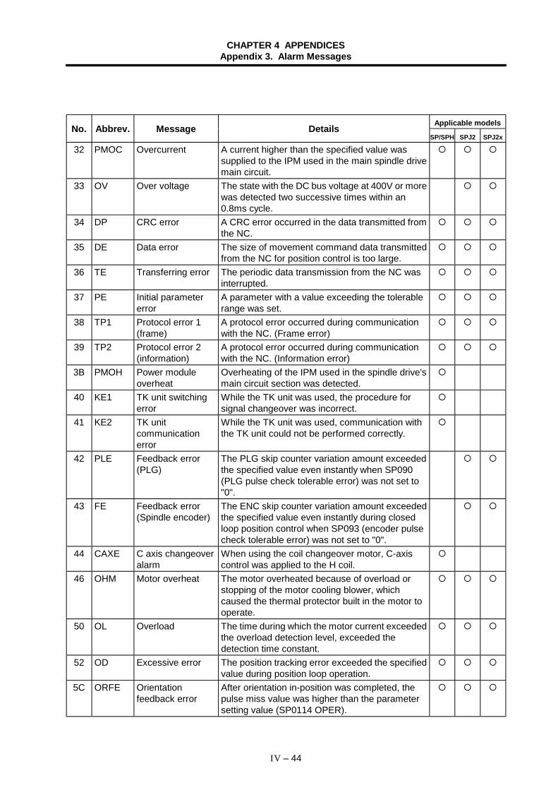
CHAPTER 4 APPENDICESAppendix 3. Alarm Messages
IV – 44
Applicable modelsNo. Abbrev. Message DetailsSP/SPH SPJ2 SPJ2x
32 PMOC Overcurrent A current higher than the specified value wassupplied to the IPM used in the main spindle drivemain circuit.
33 OV Over voltage The state with the DC bus voltage at 400V or morewas detected two successive times within an0.8ms cycle.
34 DP CRC error A CRC error occurred in the data transmitted fromthe NC.
35 DE Data error The size of movement command data transmittedfrom the NC for position control is too large.
36 TE Transferring error The periodic data transmission from the NC wasinterrupted.
37 PE Initial parametererror
A parameter with a value exceeding the tolerablerange was set.
38 TP1 Protocol error 1(frame)
A protocol error occurred during communicationwith the NC. (Frame error)
39 TP2 Protocol error 2(information)
A protocol error occurred during communicationwith the NC. (Information error)
3B PMOH Power moduleoverheat
Overheating of the IPM used in the spindle drive'smain circuit section was detected.
40 KE1 TK unit switchingerror
While the TK unit was used, the procedure forsignal changeover was incorrect.
41 KE2 TK unitcommunicationerror
While the TK unit was used, communication withthe TK unit could not be performed correctly.
42 PLE Feedback error(PLG)
The PLG skip counter variation amount exceededthe specified value even instantly when SP090(PLG pulse check tolerable error) was not set to"0".
43 FE Feedback error(Spindle encoder)
The ENC skip counter variation amount exceededthe specified value even instantly during closedloop position control when SP093 (encoder pulsecheck tolerable error) was not set to "0".
44 CAXE C axis changeoveralarm
When using the coil changeover motor, C-axiscontrol was applied to the H coil.
46 OHM Motor overheat The motor overheated because of overload orstopping of the motor cooling blower, whichcaused the thermal protector built in the motor tooperate.
50 OL Overload The time during which the motor current exceededthe overload detection level, exceeded thedetection time constant.
52 OD Excessive error The position tracking error exceeded the specifiedvalue during position loop operation.
5C ORFE Orientationfeedback error
After orientation in-position was completed, thepulse miss value was higher than the parametersetting value (SP0114 OPER).
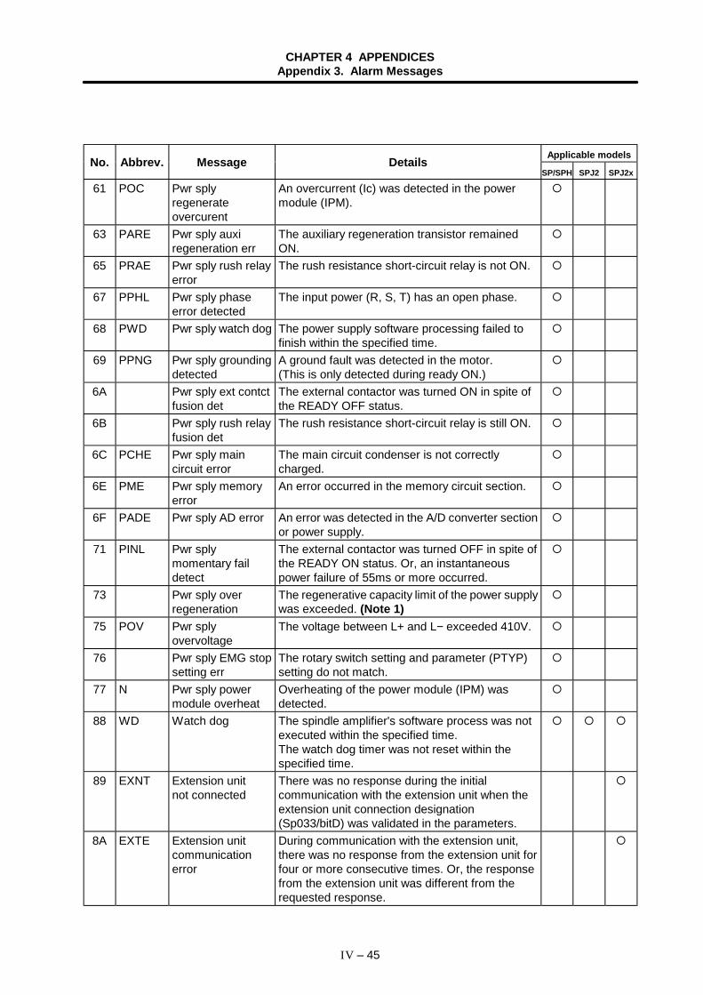
CHAPTER 4 APPENDICESAppendix 3. Alarm Messages
IV – 45
Applicable modelsNo. Abbrev. Message DetailsSP/SPH SPJ2 SPJ2x
61 POC Pwr splyregenerateovercurent
An overcurrent (Ic) was detected in the powermodule (IPM).
63 PARE Pwr sply auxiregeneration err
The auxiliary regeneration transistor remainedON.
65 PRAE Pwr sply rush relayerror
The rush resistance short-circuit relay is not ON.
67 PPHL Pwr sply phaseerror detected
The input power (R, S, T) has an open phase.
68 PWD Pwr sply watch dog The power supply software processing failed tofinish within the specified time.
69 PPNG Pwr sply groundingdetected
A ground fault was detected in the motor.(This is only detected during ready ON.)
6A Pwr sply ext contctfusion det
The external contactor was turned ON in spite ofthe READY OFF status.
6B Pwr sply rush relayfusion det
The rush resistance short-circuit relay is still ON.
6C PCHE Pwr sply maincircuit error
The main circuit condenser is not correctlycharged.
6E PME Pwr sply memoryerror
An error occurred in the memory circuit section.
6F PADE Pwr sply AD error An error was detected in the A/D converter sectionor power supply.
71 PINL Pwr splymomentary faildetect
The external contactor was turned OFF in spite ofthe READY ON status. Or, an instantaneouspower failure of 55ms or more occurred.
73 Pwr sply overregeneration
The regenerative capacity limit of the power supplywas exceeded. (Note 1)
75 POV Pwr splyovervoltage
The voltage between L+ and L− exceeded 410V.
76 Pwr sply EMG stopsetting err
The rotary switch setting and parameter (PTYP)setting do not match.
77 N Pwr sply powermodule overheat
Overheating of the power module (IPM) wasdetected.
88 WD Watch dog The spindle amplifier's software process was notexecuted within the specified time.The watch dog timer was not reset within thespecified time.
89 EXNT Extension unitnot connected
There was no response during the initialcommunication with the extension unit when theextension unit connection designation(Sp033/bitD) was validated in the parameters.
8A EXTE Extension unitcommunicationerror
During communication with the extension unit,there was no response from the extension unit forfour or more consecutive times. Or, the responsefrom the extension unit was different from therequested response.
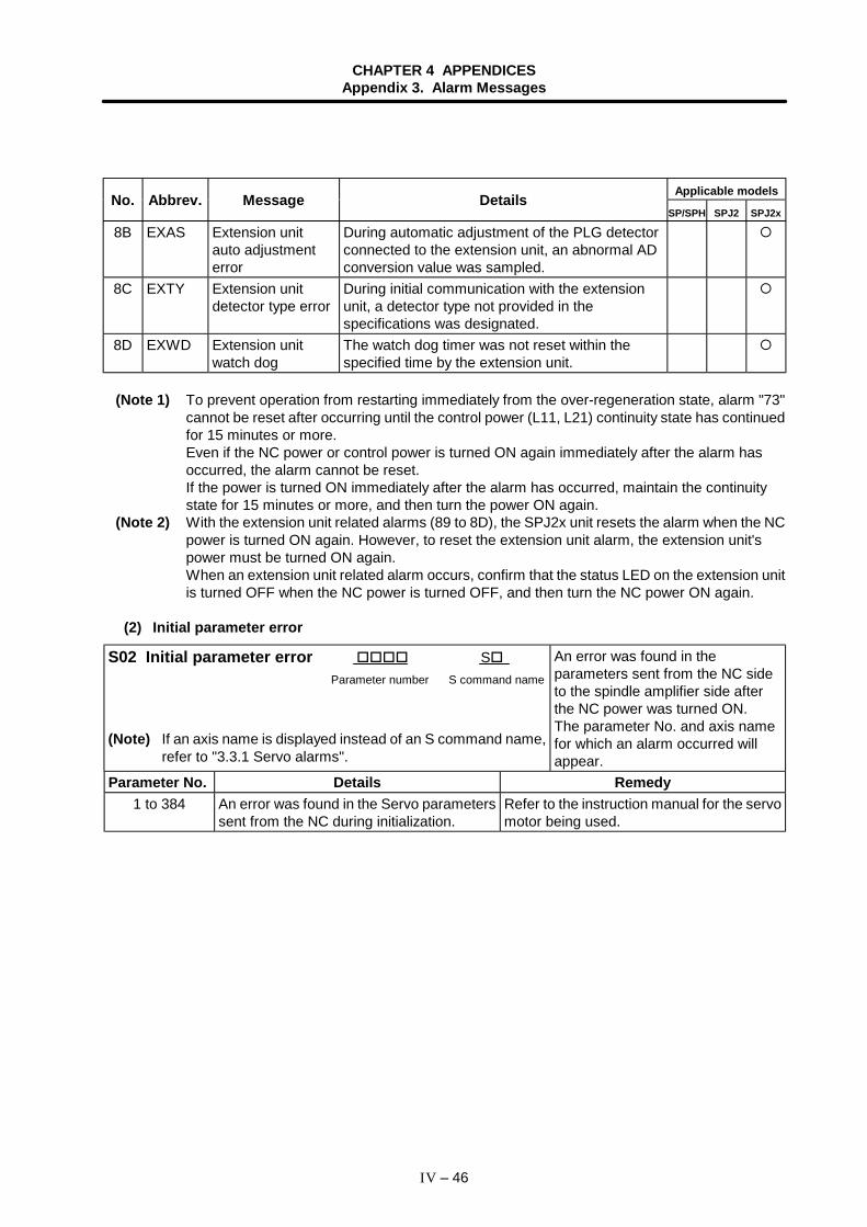
CHAPTER 4 APPENDICESAppendix 3. Alarm Messages
IV – 46
Applicable modelsNo. Abbrev. Message DetailsSP/SPH SPJ2 SPJ2x
8B EXAS Extension unitauto adjustmenterror
During automatic adjustment of the PLG detectorconnected to the extension unit, an abnormal ADconversion value was sampled.
8C EXTY Extension unitdetector type error
During initial communication with the extensionunit, a detector type not provided in thespecifications was designated.
8D EXWD Extension unitwatch dog
The watch dog timer was not reset within thespecified time by the extension unit.
(Note 1) To prevent operation from restarting immediately from the over-regeneration state, alarm "73"cannot be reset after occurring until the control power (L11, L21) continuity state has continuedfor 15 minutes or more.Even if the NC power or control power is turned ON again immediately after the alarm hasoccurred, the alarm cannot be reset.If the power is turned ON immediately after the alarm has occurred, maintain the continuitystate for 15 minutes or more, and then turn the power ON again.
(Note 2) With the extension unit related alarms (89 to 8D), the SPJ2x unit resets the alarm when the NCpower is turned ON again. However, to reset the extension unit alarm, the extension unit'spower must be turned ON again.When an extension unit related alarm occurs, confirm that the status LED on the extension unitis turned OFF when the NC power is turned OFF, and then turn the NC power ON again.
(2) Initial parameter error
S02 Initial parameter error S Parameter number S command name
(Note) If an axis name is displayed instead of an S command name,refer to "3.3.1 Servo alarms".
An error was found in theparameters sent from the NC sideto the spindle amplifier side afterthe NC power was turned ON.The parameter No. and axis namefor which an alarm occurred willappear.
Parameter No. Details Remedy1 to 384 An error was found in the Servo parameters
sent from the NC during initialization.Refer to the instruction manual for the servomotor being used.
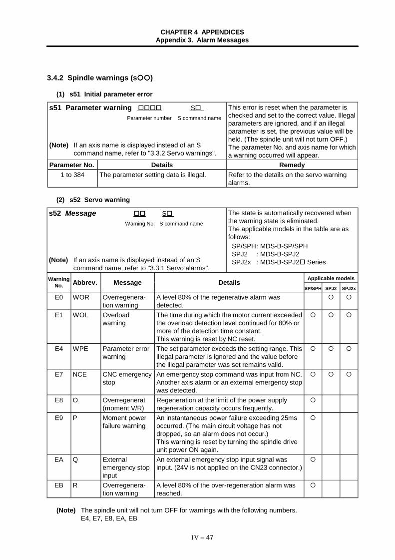
CHAPTER 4 APPENDICESAppendix 3. Alarm Messages
IV – 47
3.4.2 Spindle warnings (s )
(1) s51 Initial parameter error
s51 Parameter warning S Parameter number S command name
(Note) If an axis name is displayed instead of an Scommand name, refer to "3.3.2 Servo warnings".
This error is reset when the parameter ischecked and set to the correct value. Illegalparameters are ignored, and if an illegalparameter is set, the previous value will beheld. (The spindle unit will not turn OFF.)The parameter No. and axis name for whicha warning occurred will appear.
Parameter No. Details Remedy1 to 384 The parameter setting data is illegal. Refer to the details on the servo warning
alarms.
(2) s52 Servo warning
s52 Message S Warning No. S command name
(Note) If an axis name is displayed instead of an Scommand name, refer to "3.3.1 Servo alarms".
The state is automatically recovered whenthe warning state is eliminated.The applicable models in the table are asfollows: SP/SPH: MDS-B-SP/SPH SPJ2 : MDS-B-SPJ2 SPJ2x : MDS-B-SPJ2 Series
Applicable modelsWarningNo. Abbrev. Message Details
SP/SPH SPJ2 SPJ2x
E0 WOR Overregenera-tion warning
A level 80% of the regenerative alarm wasdetected.
E1 WOL Overloadwarning
The time during which the motor current exceededthe overload detection level continued for 80% ormore of the detection time constant.This warning is reset by NC reset.
E4 WPE Parameter errorwarning
The set parameter exceeds the setting range. Thisillegal parameter is ignored and the value beforethe illegal parameter was set remains valid.
E7 NCE CNC emergencystop
An emergency stop command was input from NC.Another axis alarm or an external emergency stopwas detected.
E8 O Overregenerat(moment V/R)
Regeneration at the limit of the power supplyregeneration capacity occurs frequently.
E9 P Moment powerfailure warning
An instantaneous power failure exceeding 25msoccurred. (The main circuit voltage has notdropped, so an alarm does not occur.)This warning is reset by turning the spindle driveunit power ON again.
EA Q Externalemergency stopinput
An external emergency stop input signal wasinput. (24V is not applied on the CN23 connector.)
EB R Overregenera-tion warning
A level 80% of the over-regeneration alarm wasreached.
(Note) The spindle unit will not turn OFF for warnings with the following numbers.E4, E7, E8, EA, EB
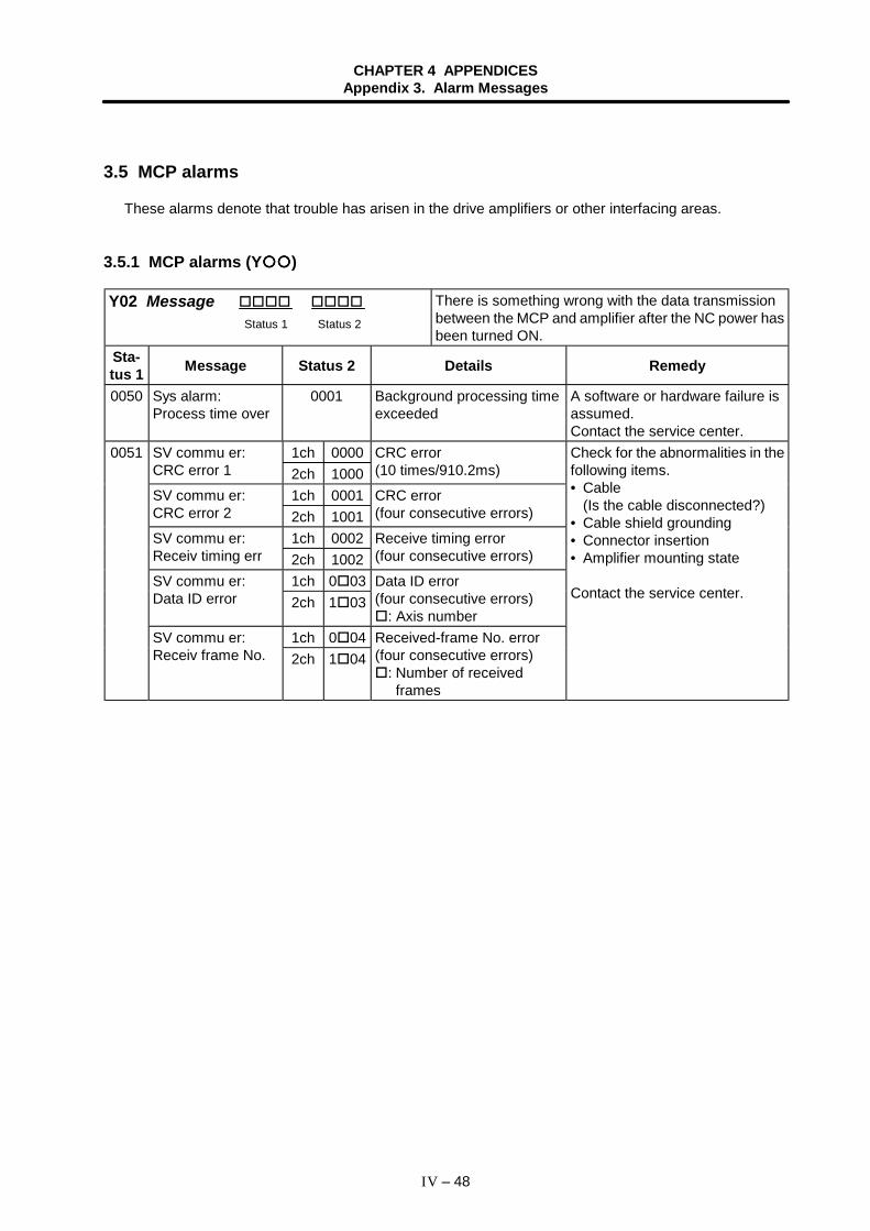
CHAPTER 4 APPENDICESAppendix 3. Alarm Messages
IV – 48
3.5 MCP alarms
These alarms denote that trouble has arisen in the drive amplifiers or other interfacing areas.
3.5.1 MCP alarms (Y )
Y02 Message Status 1 Status 2
There is something wrong with the data transmissionbetween the MCP and amplifier after the NC power hasbeen turned ON.
Sta-tus 1 Message Status 2 Details Remedy
0050 Sys alarm:Process time over
0001 Background processing timeexceeded
A software or hardware failure isassumed.Contact the service center.
1ch 0000SV commu er:CRC error 1 2ch 1000
CRC error(10 times/910.2ms)
1ch 0001SV commu er:CRC error 2 2ch 1001
CRC error(four consecutive errors)
1ch 0002SV commu er:Receiv timing err 2ch 1002
Receive timing error(four consecutive errors)
1ch 0 03SV commu er:Data ID error 2ch 1 03
Data ID error(four consecutive errors)
: Axis number1ch 0 04
0051
SV commu er:Receiv frame No. 2ch 1 04
Received-frame No. error(four consecutive errors)
: Number of receivedframes
Check for the abnormalities in thefollowing items.• Cable
(Is the cable disconnected?)• Cable shield grounding• Connector insertion• Amplifier mounting state
Contact the service center.
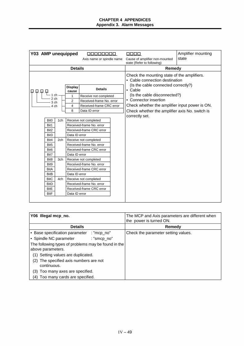
CHAPTER 4 APPENDICESAppendix 3. Alarm Messages
IV – 49
Y03 AMP unequipped Axis name or spindle name Cause of amplifier non-mounted
state (Refer to following)
Amplifier mountingstate
Details Remedy
1 ch2 ch3 ch4 ch
Check the mounting state of the amplifiers.• Cable connection destination
(Is the cable connected correctly?)• Cable
(Is the cable disconnected?)• Connector insertionCheck whether the amplifier input power is ON.Check whether the amplifier axis No. switch iscorrectly set.
Y06 Illegal mcp_no. The MCP and Axis parameters are different whenthe power is turned ON.
Details Remedy• Base specification parameter : "mcp_no"• Spindle NC parameter : "smcp_no"The following types of problems may be found in theabove parameters.
(1) Setting values are duplicated.(2) The specified axis numbers are not
continuous.(3) Too many axes are specified.(4) Too many cards are specified.
Check the parameter setting values.
Bit0 1ch Receive not completedBit1 Received-frame No. errorBit2 Received-frame CRC errorBit3 Data ID errorBit4 2ch Receive not completedBit5 Received-frame No. errorBit6 Received-frame CRC errorBit7 Data ID errorBit8 3ch Receive not completedBit9 Received-frame No. errorBitA Received-frame CRC errorBitB Data ID errorBitC 4ch Receive not completedBitD Received-frame No. errorBitE Received-frame CRC errorBitF Data ID error
Displaycause Details
1 Receive not completed2 Received-frame No. error4 Received-frame CRC error8 Data ID error
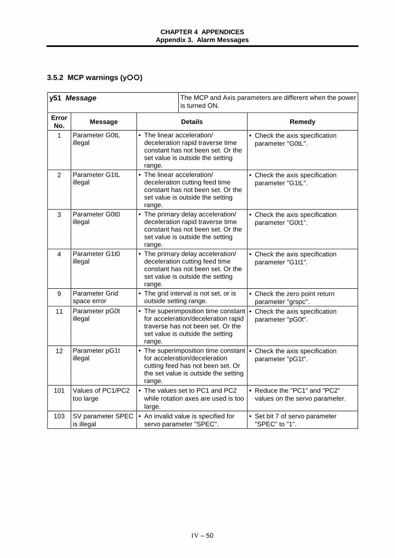
CHAPTER 4 APPENDICESAppendix 3. Alarm Messages
IV – 50
3.5.2 MCP warnings (y )
y51 Message The MCP and Axis parameters are different when the poweris turned ON.
ErrorNo. Message Details Remedy
1 Parameter G0tLillegal
• The linear acceleration/deceleration rapid traverse timeconstant has not been set. Or theset value is outside the settingrange.
• Check the axis specificationparameter "G0tL".
2 Parameter G1tLillegal
• The linear acceleration/deceleration cutting feed timeconstant has not been set. Or theset value is outside the settingrange.
• Check the axis specificationparameter "G1tL".
3 Parameter G0t0illegal
• The primary delay acceleration/deceleration rapid traverse timeconstant has not been set. Or theset value is outside the settingrange.
• Check the axis specificationparameter "G0t1".
4 Parameter G1t0illegal
• The primary delay acceleration/deceleration cutting feed timeconstant has not been set. Or theset value is outside the settingrange.
• Check the axis specificationparameter "G1t1".
9 Parameter Gridspace error
• The grid interval is not set, or isoutside setting range.
• Check the zero point returnparameter "grspc".
11 Parameter pG0tillegal
• The superimposition time constantfor acceleration/deceleration rapidtraverse has not been set. Or theset value is outside the settingrange.
• Check the axis specificationparameter "pG0t".
12 Parameter pG1tillegal
• The superimposition time constantfor acceleration/decelerationcutting feed has not been set. Orthe set value is outside the settingrange.
• Check the axis specificationparameter "pG1t".
101 Values of PC1/PC2too large
• The values set to PC1 and PC2while rotation axes are used is toolarge.
• Reduce the "PC1" and "PC2"values on the servo parameter.
103 SV parameter SPECis illegal
• An invalid value is specified forservo parameter "SPEC".
• Set bit 7 of servo parameter"SPEC" to "1".
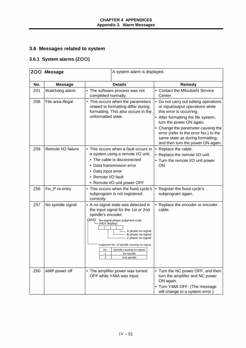
CHAPTER 4 APPENDICESAppendix 3. Alarm Messages
IV – 51
3.6 Messages related to system
3.6.1 System alarms (Z )
Z Message A system alarm is displayed.
No. Message Details RemedyZ01 Watchdog alarm • The software process was not
completed normally.• Contact the Mitsubishi Service
Center.Z08 File area illegal • This occurs when the parameters
related to formatting differ duringformatting. This also occurs in theunformatted state.
• Do not carry out editing operationsor input/output operations whilethis error is occurring.
• After formatting the file system,turn the power ON again.
• Change the parameter causing theerror (refer to the error No.) to thesame state as during formatting,and then turn the power ON again.
Z09 Remote I/O failure • This occurs when a fault occurs ina system using a remote I/O unit.• The cable is disconnected• Data transmission error• Data input error• Remote I/O fault• Remote I/O unit power OFF
• Replace the cable.• Replace the remote I/O unit.• Turn the remote I/O unit power
ON.
Z56 Fix_P re-entry • This occurs when the fixed cycle’ssubprogram is not registeredcorrectly.
• Register the fixed cycle’ssubprogram again.
Z57 No spindle signal • A no-signal state was detected inthe input signal for the 1st or 2ndspindle's encoder.
No. Spindle causing no-signal1 1st spindle2 2nd spindle
00 No-signal phase judgment code(HEX display)
Judgment No. of spindle causing no-signal
A phase no-signalB phase no-signalZ phase no-signal
• Replace the encoder or encodercable.
Z60 AMP power off • The amplifier power was turnedOFF while Y48A was input.
• Turn the NC power OFF, and thenturn the amplifier and NC powerON again.
• Turn Y48A OFF. (The messagewill change to a system error.)
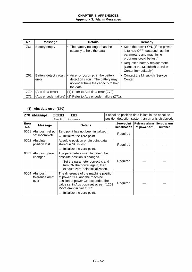
CHAPTER 4 APPENDICESAppendix 3. Alarm Messages
IV – 52
No. Message Details RemedyZ61 Battery empty • The battery no longer has the
capacity to hold the data.• Keep the power ON. (If the power
is turned OFF, data such as theparameters and machiningprograms could be lost.)
• Request a battery replacement.(Contact the Mitsubishi ServiceCenter immediately.)
Z62 Battery detect circuiterror
• An error occurred in the batterydetection circuit. The battery mayno longer have the capacity to holdthe data.
• Contact the Mitsubishi ServiceCenter.
Z70 (Abs data error) (1) Refer to Abs data error (Z70).Z71 (Abs encoder failure) (2) Refer to Abs encoder failure (Z71).
(1) Abs data error (Z70)
Z70 Message Error No. Axis name
If absolute position data is lost in the absoluteposition detection system, an error is displayed.
ErrorNo. Message Details Zero-point
initializationRelease alarmat power-off
Servo alarmnumber
0001 Abs posn ref ptset incomplete
Zero point has not been initialized.→ Initialize the zero point.
Required — —
0002 Absoluteposition lost
Absolute position origin point datastored in NC is lost.→ Initialize the zero point.
Required — —
0003 Abs posn paramchanged
The parameters used to detect theabsolute position is changed.→ Set the parameter correctly, and
turn ON the power again, thenexecute zero-point initialization.
Required — —
0004 Abs posntolerance amntover
The difference of the machine positionat power OFF and the machineposition at power ON exceeded thevalue set in Abs posn set screen "1203Move amnt in pwr OFF".→ Initialize the zero point.
Required — —
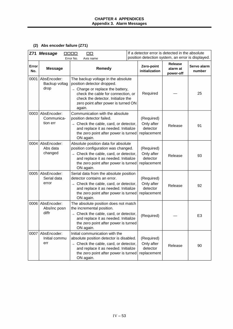
CHAPTER 4 APPENDICESAppendix 3. Alarm Messages
IV – 53
(2) Abs encoder failure (Z71)
Z71 Message Error No. Axis name
If a detector error is detected in the absoluteposition detection system, an error is displayed.
ErrorNo. Message Remedy Zero-point
initialization
Releasealarm at
power-off
Servo alarmnumber
0001 AbsEncoder:Backup voltagdrop
The backup voltage in the absoluteposition detector dropped.→ Charge or replace the battery,
check the cable for connection, orcheck the detector. Initialize thezero point after power is turned ONagain.
Required — 25
0003 AbsEncoder:Communica-tion err
Communication with the absoluteposition detector failed.→ Check the cable, card, or detector,
and replace it as needed. Initializethe zero point after power is turnedON again.
(Required)Only afterdetector
replacement
Release 91
0004 AbsEncoder:Abs datachanged
Absolute position data for absoluteposition configuration was changed.→ Check the cable, card, or detector,
and replace it as needed. Initializethe zero point after power is turnedON again.
(Required)Only afterdetector
replacement
Release 93
0005 AbsEncoder:Serial dataerror
Serial data from the absolute positiondetector contains an error.→ Check the cable, card, or detector,
and replace it as needed. Initializethe zero point after power is turnedON again.
(Required)Only afterdetector
replacement
Release 92
0006 AbsEncoder:Abs/inc posndiffr
The absolute position does not matchthe incremental position.→ Check the cable, card, or detector,
and replace it as needed. Initializethe zero point after power is turnedON again.
(Required) — E3
0007 AbsEncoder:Initial commuerr
Initial communication with theabsolute position detector is disabled.→ Check the cable, card, or detector,
and replace it as needed. Initializethe zero point after power is turnedON again.
(Required)Only afterdetector
replacement
Release 90
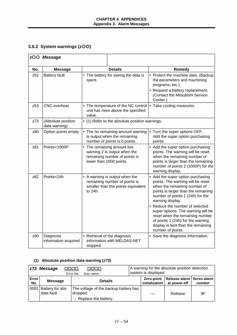
CHAPTER 4 APPENDICESAppendix 3. Alarm Messages
IV – 54
3.6.2 System warnings (z )
z Message
No. Message Details Remedyz52 Battery fault • The battery for saving the data is
spent.• Protect the machine data. (Backup
the parameters and machiningprograms, etc.)
• Request a battery replacement.(Contact the Mitsubishi ServiceCenter.)
z53 CNC overheat • The temperature of the NC controlunit has risen above the specifiedvalue.
• Take cooling measures.
z73 (Absolute positiondata warning)
• (1) Refer to the absolute position warnings.
z80 Option points empty • The no remaining amount warningis output when the remainingnumber of points is 0 points.
• Turn the super options OFF.Add the super option purchasingpoints.
z81 Points<1000P • The remaining amount lowwarning 2 is output when theremaining number of points islower than 1000 points.
• Add the super option purchasingpoints. The warning will be resetwhen the remaining number ofpoints is larger than the remainingnumber of points 2 (1000P) for thewarning display.
z82 Points<24h • A warning is output when theremaining number of points issmaller than the points equivalentto 24h.
• Add the super option purchasingpoints. The warning will be resetwhen the remaining number ofpoints is larger than the remainingnumber of points 1 (24h) for thewarning display.
• Reduce the number of selectedsuper options. The warning will bereset when the remaining numberof points 1 (24h) for the warningdisplay is less than the remainingnumber of points.
z90 Diagnosisinformation acquired
• Retrieval of the diagnosisinformation with MELDAS-NETstopped.
• Save the diagnosis information.
(1) Absolute position data warning (z73)
z73 Message Error No. Axis name
A warning for the absolute position detectionsystem is displayed.
ErrorNo. Message Details Zero-point
initializationRelease alarmat power-off
Servo alarmnumber
0001 Battery for absdata fault
The voltage of the backup battery hasdropped.→ Replace the battery.
— Release 9F
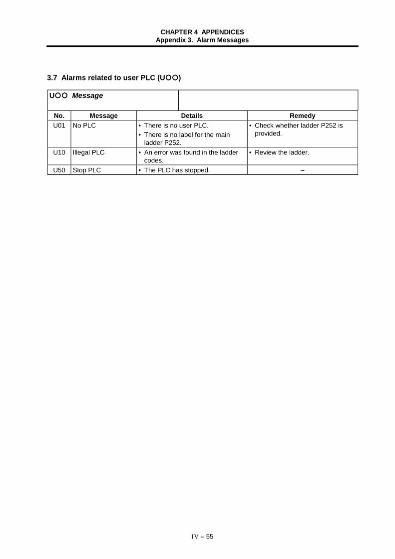
CHAPTER 4 APPENDICESAppendix 3. Alarm Messages
IV – 55
3.7 Alarms related to user PLC (U )
U Message
No. Message Details RemedyU01 No PLC • There is no user PLC.
• There is no label for the mainladder P252.
• Check whether ladder P252 isprovided.
U10 Illegal PLC • An error was found in the laddercodes.
• Review the ladder.
U50 Stop PLC • The PLC has stopped. –
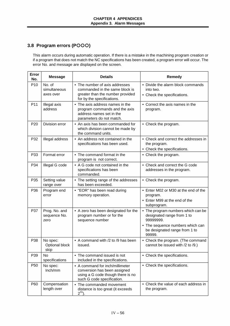
CHAPTER 4 APPENDICESAppendix 3. Alarm Messages
IV – 56
3.8 Program errors (P )
This alarm occurs during automatic operation. If there is a mistake in the machining program creation orif a program that does not match the NC specifications has been created, a program error will occur. Theerror No. and message are displayed on the screen.
ErrorNo. Message Details Remedy
P10 No. ofsimultaneousaxes over
• The number of axis addressescommanded in the same block isgreater than the number providedfor by the specifications.
• Divide the alarm block commandsinto two.
• Check the specifications.
P11 Illegal axisaddress
• The axis address names in theprogram commands and the axisaddress names set in theparameters do not match.
• Correct the axis names in theprogram.
P20 Division error • An axis has been commanded forwhich division cannot be made bythe command units.
• Check the program.
P32 Illegal address • An address not contained in thespecifications has been used.
• Check and correct the addresses inthe program.
• Check the specifications.P33 Format error • The command format in the
program is not correct.• Check the program.
P34 Illegal G code • A G code not contained in thespecifications has beencommanded.
• Check and correct the G codeaddresses in the program.
P35 Setting valuerange over
• The setting range of the addresseshas been exceeded.
• Check the program.
P36 Program enderror
• "EOR" has been read duringmemory operation.
• Enter M02 or M30 at the end of theprogram.
• Enter M99 at the end of thesubprogram.
P37 Prog. No. andsequence No.zero
• A zero has been designated for theprogram number or for thesequence number
• The program numbers which can bedesignated range from 1 to99999999.
• The sequence numbers which canbe designated range from 1 to99999.
P38 No spec:Optional blockskip
• A command with /2 to /9 has beenissued.
• Check the program. (The commandcannot be issued with /2 to /9.)
P39 Nospecifications
• The command issued is notincluded in the specifications.
• Check the specifications.
P50 No spec:Inch/mm
• A command for inch/millimeterconversion has been assignedusing a G code though there is nosuch G code specification.
• Check the specifications.
P60 Compensationlength over
• The commanded movementdistance is too great (it exceeds231).
• Check the value of each address inthe program.
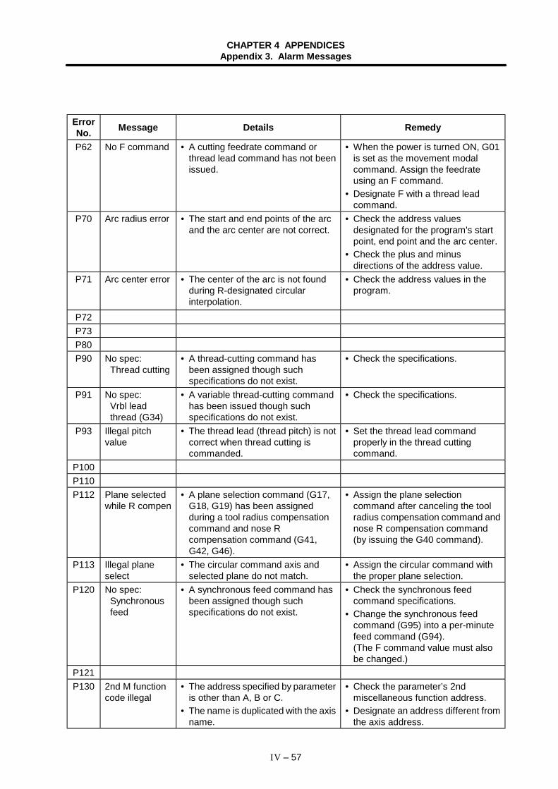
CHAPTER 4 APPENDICESAppendix 3. Alarm Messages
IV – 57
ErrorNo. Message Details Remedy
P62 No F command • A cutting feedrate command orthread lead command has not beenissued.
• When the power is turned ON, G01is set as the movement modalcommand. Assign the feedrateusing an F command.
• Designate F with a thread leadcommand.
P70 Arc radius error • The start and end points of the arcand the arc center are not correct.
• Check the address valuesdesignated for the program's startpoint, end point and the arc center.
• Check the plus and minusdirections of the address value.
P71 Arc center error • The center of the arc is not foundduring R-designated circularinterpolation.
• Check the address values in theprogram.
P72P73P80P90 No spec:
Thread cutting• A thread-cutting command has
been assigned though suchspecifications do not exist.
• Check the specifications.
P91 No spec:Vrbl leadthread (G34)
• A variable thread-cutting commandhas been issued though suchspecifications do not exist.
• Check the specifications.
P93 Illegal pitchvalue
• The thread lead (thread pitch) is notcorrect when thread cutting iscommanded.
• Set the thread lead commandproperly in the thread cuttingcommand.
P100P110P112 Plane selected
while R compen• A plane selection command (G17,
G18, G19) has been assignedduring a tool radius compensationcommand and nose Rcompensation command (G41,G42, G46).
• Assign the plane selectioncommand after canceling the toolradius compensation command andnose R compensation command(by issuing the G40 command).
P113 Illegal planeselect
• The circular command axis andselected plane do not match.
• Assign the circular command withthe proper plane selection.
P120 No spec:Synchronousfeed
• A synchronous feed command hasbeen assigned though suchspecifications do not exist.
• Check the synchronous feedcommand specifications.
• Change the synchronous feedcommand (G95) into a per-minutefeed command (G94).(The F command value must alsobe changed.)
P121 P130 2nd M function
code illegal• The address specified by parameter
is other than A, B or C.• The name is duplicated with the axis
name.
• Check the parameter’s 2ndmiscellaneous function address.
• Designate an address different fromthe axis address.
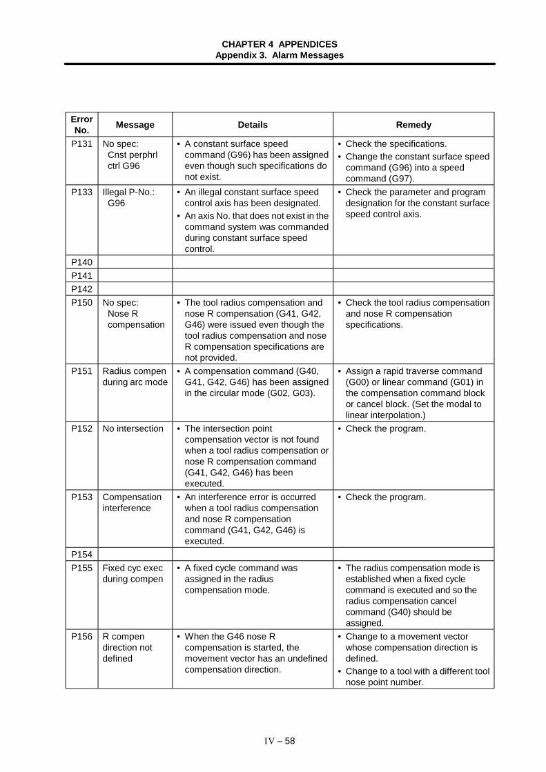
CHAPTER 4 APPENDICESAppendix 3. Alarm Messages
IV – 58
ErrorNo. Message Details Remedy
P131 No spec:Cnst perphrlctrl G96
• A constant surface speedcommand (G96) has been assignedeven though such specifications donot exist.
• Check the specifications.• Change the constant surface speed
command (G96) into a speedcommand (G97).
P133 Illegal P-No.:G96
• An illegal constant surface speedcontrol axis has been designated.
• An axis No. that does not exist in thecommand system was commandedduring constant surface speedcontrol.
• Check the parameter and programdesignation for the constant surfacespeed control axis.
P140P141P142P150 No spec:
Nose Rcompensation
• The tool radius compensation andnose R compensation (G41, G42,G46) were issued even though thetool radius compensation and noseR compensation specifications arenot provided.
• Check the tool radius compensationand nose R compensationspecifications.
P151 Radius compenduring arc mode
• A compensation command (G40,G41, G42, G46) has been assignedin the circular mode (G02, G03).
• Assign a rapid traverse command(G00) or linear command (G01) inthe compensation command blockor cancel block. (Set the modal tolinear interpolation.)
P152 No intersection • The intersection pointcompensation vector is not foundwhen a tool radius compensation ornose R compensation command(G41, G42, G46) has beenexecuted.
• Check the program.
P153 Compensationinterference
• An interference error is occurredwhen a tool radius compensationand nose R compensationcommand (G41, G42, G46) isexecuted.
• Check the program.
P154 P155 Fixed cyc exec
during compen• A fixed cycle command was
assigned in the radiuscompensation mode.
• The radius compensation mode isestablished when a fixed cyclecommand is executed and so theradius compensation cancelcommand (G40) should beassigned.
P156 R compendirection notdefined
• When the G46 nose Rcompensation is started, themovement vector has an undefinedcompensation direction.
• Change to a movement vectorwhose compensation direction isdefined.
• Change to a tool with a different toolnose point number.
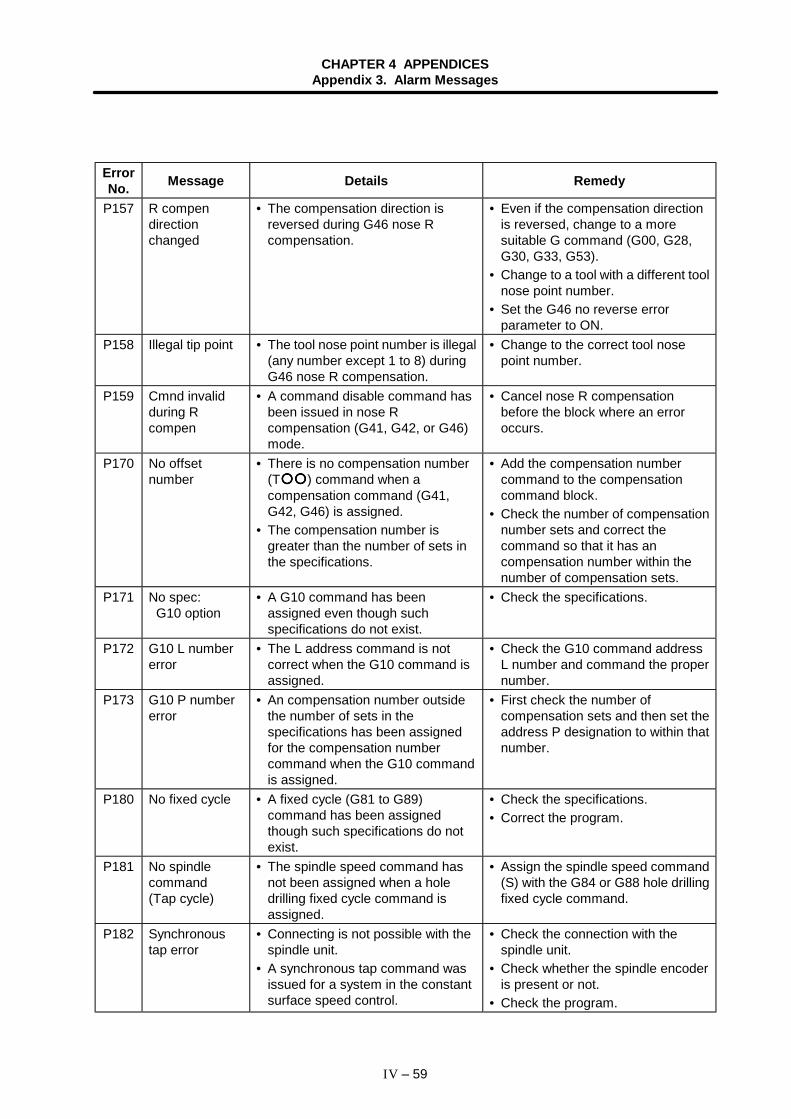
CHAPTER 4 APPENDICESAppendix 3. Alarm Messages
IV – 59
ErrorNo. Message Details Remedy
P157 R compendirectionchanged
• The compensation direction isreversed during G46 nose Rcompensation.
• Even if the compensation directionis reversed, change to a moresuitable G command (G00, G28,G30, G33, G53).
• Change to a tool with a different toolnose point number.
• Set the G46 no reverse errorparameter to ON.
P158 Illegal tip point • The tool nose point number is illegal(any number except 1 to 8) duringG46 nose R compensation.
• Change to the correct tool nosepoint number.
P159 Cmnd invalidduring Rcompen
• A command disable command hasbeen issued in nose Rcompensation (G41, G42, or G46)mode.
• Cancel nose R compensationbefore the block where an erroroccurs.
P170 No offsetnumber
• There is no compensation number(T ) command when acompensation command (G41,G42, G46) is assigned.
• The compensation number isgreater than the number of sets inthe specifications.
• Add the compensation numbercommand to the compensationcommand block.
• Check the number of compensationnumber sets and correct thecommand so that it has ancompensation number within thenumber of compensation sets.
P171 No spec:G10 option
• A G10 command has beenassigned even though suchspecifications do not exist.
• Check the specifications.
P172 G10 L numbererror
• The L address command is notcorrect when the G10 command isassigned.
• Check the G10 command addressL number and command the propernumber.
P173 G10 P numbererror
• An compensation number outsidethe number of sets in thespecifications has been assignedfor the compensation numbercommand when the G10 commandis assigned.
• First check the number ofcompensation sets and then set theaddress P designation to within thatnumber.
P180 No fixed cycle • A fixed cycle (G81 to G89)command has been assignedthough such specifications do notexist.
• Check the specifications.• Correct the program.
P181 No spindlecommand(Tap cycle)
• The spindle speed command hasnot been assigned when a holedrilling fixed cycle command isassigned.
• Assign the spindle speed command(S) with the G84 or G88 hole drillingfixed cycle command.
P182 Synchronoustap error
• Connecting is not possible with thespindle unit.
• A synchronous tap command wasissued for a system in the constantsurface speed control.
• Check the connection with thespindle unit.
• Check whether the spindle encoderis present or not.
• Check the program.
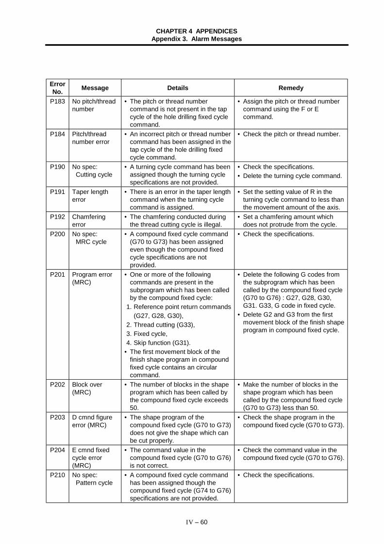
CHAPTER 4 APPENDICESAppendix 3. Alarm Messages
IV – 60
ErrorNo. Message Details Remedy
P183 No pitch/threadnumber
• The pitch or thread numbercommand is not present in the tapcycle of the hole drilling fixed cyclecommand.
• Assign the pitch or thread numbercommand using the F or Ecommand.
P184 Pitch/threadnumber error
• An incorrect pitch or thread numbercommand has been assigned in thetap cycle of the hole drilling fixedcycle command.
• Check the pitch or thread number.
P190 No spec:Cutting cycle
• A turning cycle command has beenassigned though the turning cyclespecifications are not provided.
• Check the specifications.• Delete the turning cycle command.
P191 Taper lengtherror
• There is an error in the taper lengthcommand when the turning cyclecommand is assigned.
• Set the setting value of R in theturning cycle command to less thanthe movement amount of the axis.
P192 Chamferingerror
• The chamfering conducted duringthe thread cutting cycle is illegal.
• Set a chamfering amount whichdoes not protrude from the cycle.
P200 No spec:MRC cycle
• A compound fixed cycle command(G70 to G73) has been assignedeven though the compound fixedcycle specifications are notprovided.
• Check the specifications.
P201 Program error(MRC)
• One or more of the followingcommands are present in thesubprogram which has been calledby the compound fixed cycle:
1. Reference point return commands (G27, G28, G30),2. Thread cutting (G33),3. Fixed cycle,4. Skip function (G31).
• The first movement block of thefinish shape program in compoundfixed cycle contains an circularcommand.
• Delete the following G codes fromthe subprogram which has beencalled by the compound fixed cycle(G70 to G76) : G27, G28, G30,G31. G33, G code in fixed cycle.
• Delete G2 and G3 from the firstmovement block of the finish shapeprogram in compound fixed cycle.
P202 Block over(MRC)
• The number of blocks in the shapeprogram which has been called bythe compound fixed cycle exceeds50.
• Make the number of blocks in theshape program which has beencalled by the compound fixed cycle(G70 to G73) less than 50.
P203 D cmnd figureerror (MRC)
• The shape program of thecompound fixed cycle (G70 to G73)does not give the shape which canbe cut properly.
• Check the shape program in thecompound fixed cycle (G70 to G73).
P204 E cmnd fixedcycle error(MRC)
• The command value in thecompound fixed cycle (G70 to G76)is not correct.
• Check the command value in thecompound fixed cycle (G70 to G76).
P210 No spec:Pattern cycle
• A compound fixed cycle commandhas been assigned though thecompound fixed cycle (G74 to G76)specifications are not provided.
• Check the specifications.
CHAPTER 4 APPENDICESAppendix 3. Alarm Messages
IV – 61
ErrorNo. Message Details Remedy
P230 Sub-programnesting over
• The number of times subprogramshave been called in sequence fromsubprograms has exceeded 8.
• Check the number of subprogramcalls and correct the program sothat it does not exceed 8.
P231 No sequenceNo.
• The sequence number commandedby GOTO has not been set whencalling out a subprogram or whenreturning to the main program froma subprogram.
• Enter the sequence number in theappropriate block.
P232 No program No. • The subprogram has not beenregistered when it is called.
• Register the subprogram.
P240 No spec:Variablecommand
• A variable command has beenassigned though suchspecifications (# ) do not exist.
• Check the specifications.• Delete the variable command.
P241 No variable No. • The commanded variable numberis higher than the variable numbersin the specifications.
• Check the specifications.• Check the program variable
numbers.P242 " = " not defined
at vrble set• " = " has not been commanded
when a variable is defined.• Set " = " into the program variable
definition.P250P251P252P260P270 No spec:
User macro• A macro specification command
has been assigned though suchspecifications do not exist.
• Check the specifications.• Delete the macro command.
P271 No spec:Macrointerrupt
• A macro interrupt command hasbeen issued though it is notincluded in the specifications.
• Check the specifications.
P272 NC and macrotexts in a block
• An NC statement and a macrostatement exist in the same block.
• Check the program, and programso that the NC statement and macrostatement are in separate blocks.
P273 Macro callnesting over
• The maximum number of macrocall nesting levels have beenexceeded.
• Check the program and correct sothat the macro calls do not exceedthe number of levels provided for bythe specifications.
P275 Macroargument over
• There are too many argument setsin macro call argument type II.
• Check the program.
P276 Illegal G67command
• A G67 command has beenassigned though it is not during theG66 command modal.
• Check the program.• The G67 command serves to
cancel the call and so the G66command is assigned before thiscommand.
P277 Macro alarmmessage
• An alarm command has beenissued in user macro.
• Check the user macro program.
P280 Brackets [ ]nesting over
• More than 5 bracket " [ " or " ] "parentheses have been used in ablock.
• Check the program and correct sothat the number of " [ " or " ] "parentheses does not exceed 5bracket.
CHAPTER 4 APPENDICESAppendix 3. Alarm Messages
IV – 62
ErrorNo. Message Details Remedy
P281 Brackets [ ] notpaired
• The number of the " [ " or " ] "parentheses commanded in a blockdoes not match.
• Check the program and correct sothat the numbers of " [ " and " ] "parentheses are paired off properly.
P282 Calculationimpossible
• An operation formula is not correct. • Check the program and correct theoperation formula.
P283 Divided by zero • The division denominator is zero. • Check the program and correct sothat the denominator for division inthe operation formula is not zero.
P284 Integer valueoverflow
• In the process of operation theinteger value has exceeded –231
(231–1).
• Check the operation formula in theprogram and correct so that thevalue of the integers after theoperation does not exceed –231.
P285 Float valueoverflow
• There is a variable data overflow. • Check the variable data in theprogram.
P290 IF sentenceerror
• There is an error in the IF[<conditional formula>] GOTOstatement.
• Check the program.
P291 WHILEsentence error
• There is an error in the WHILE [<conditional formula>] DO toEND statement.
• Check the program.
P292 SETVNsentence error
• The variable name setting orSETVN statement is incorrect.
• Check the program.• Make sure that the variable name of
the SETVN statement has 7 orfewer characters.
P293 DO-ENDnesting over
• The numbers of ’s in the DOand END of the WHILE[<conditional formula>] DO toEND statement (nesting levels)has been exceeded 27.
• Check the program and correct sothat the nesting levels of DO to ENDstatements does not exceed 27.
P294 DO and ENDnot paired
• The DO and END are not paired offproperly.
• Check the program and correct sothat the DO and END are paired offproperly.
P300 Variable nameillegal
• A variable name has not beencommanded properly.
• Correct the program so that thevariable name is correct.
• Check the variable names in theprogram and correct them.
P301 Variable nameduplicated
• A variable name has beenduplicated.
• Correct the program so that thevariable names are not duplicated.
P370 No spec:Mirr imagedubl turet
• An opposite tool rest mirror imagecommand (G68) has been assignedthough the double-turret mirrorimage specifications are notprovided.
• Check the specifications.
P380 No spec:Corner R/C
• A corner chamfering (C) or cornerrounding (R) command has beenassigned though the cornerchamfering and corner rounding Iand II specifications do not exist.
• Check the specifications.• Remove "corner R" and "corner C"
from the program.
CHAPTER 4 APPENDICESAppendix 3. Alarm Messages
IV – 63
ErrorNo. Message Details Remedy
P381 No spec:Arc R/C
• A corner chamfering (C) or cornerrounding (R) command has beenassigned in a circular interpolationblock though the corner chamferingand corner rounding IIspecifications do not exist.
• Check the specifications.
P382 No cornermovement
• There is no movement command inthe block following the cornerchamfering/rounding.
• Assign the block following thecorner R/C command in the blockwith movement.
P383 Cornermovement short
• The movement distance is shorterthan the corner R/C commandwhen such a command is assigned.
• Since the movement distance isshorter than the corner R/C, thecorner R/C should be reduced toless than the movement distance.
P384 Corner nextmovement short
• With a corner R/C command, themovement distance in the followingblock is shorter than the corner R/C.
• Since the movement distance in thefollowing block is shorter than thecorner R/C, the corner R/C shouldbe made less than the movementdistance.
P385 Corner duringG0/G33
• G0 or G33 is contained in the blockfollowing the corner R/C.
• Check the program.
P390 No spec:Geometric
• A geometric command has beenissued while geometric 1 is notincluded in the specifications.
• Check the specifications.
P391 No spec:Geometric arc
• A geometric command has beenissued while geometric 2 is notincluded in the specifications.
• Check the specifications.
P392 Angle<1 degree(GEOMT)
• The difference in the angle betweengeometric lines is less than 1degree.
• Correct the geometric angle.
P393 Inc value in 2ndblock (GEOMT)
• The commands in the secondgeometric block have beenassigned as incremental values.
• Assign the commands in thesecond geometric block as absolutevalues.
P394 No linear movecommand(GEOMT)
• There is no linear command in thesecond geometric block.
• Assign the linear command (G01) inthe second block.
P395 Illegal address(GEOMT)
• The geometric format is incorrect. • Check the program.
P396 Plane selectedin GEOMT ctrl
• A plane selection command wasassigned in the geometriccommand.
• Select the plane before issuing thegeometric command.
P397 Arc error(GEOMT)
• The arc end point did not contact orintersect with the next block's startpoint during geometric IB, II.
• Check the previous and nextcommands including the geometricarc command.
P398 No spec:Geometric 1B
• The geometric command wasissued when the geometric IBspecifications were not available.
• Check the specifications.
P399 Direction error(GEOMT)
• The monotone is not incrementedor decremented in geometric II.
• Check the program so that themonotone is incremented ordecremented.
CHAPTER 4 APPENDICESAppendix 3. Alarm Messages
IV – 64
ErrorNo. Message Details Remedy
P410 No spec:Addressconvertor
• The specifications for convertingabsolute/incremental axisaddresses do not exist.
• Check the specifications.
P420 No spec:Parameterinput
• A parameter input command hasbeen assigned though suchspecifications do not exist.
• Check the specifications.
P421 Parameter inputerror
• The commanded parameternumber and setting data is illegal.
• An illegal G command address hasbeen assigned in the parameterinput mode.
• A parameter input command hasbeen assigned during a fixed cyclemodal or nose R compensation.
• Check the program.
P430 Zero return notcompleted
• A movement command exceptreference point return has beenassigned for an axis which has notreturned to the reference point.
• Execute the reference point returnmanually.
P431 No spec:2, 3, 4th ref-point ret
• A 2nd, 3rd or 4th reference pointreturn command has been assignedthough such specifications do notexist.
• Check the specifications.
P432 No spec: G29 • A start position return command(G29) has been assigned thoughsuch specifications do not exist.
• Check the specifications.
P433 No spec: G27 • A zero point check command (G27)has been assigned though suchspecifications do not exist.
• Check the specifications.
P434 Compare error • There is an axis which does notreturn to the zero point positionwhen the zero point checkcommand (G27) is executed.
• Check the program.
P435 G27 and Mcommands in ablock
• An M independent command hasbeen assigned simultaneously inthe G27 command block.
• An M independent commandcannot be assigned in the G27command block and so the G27command and M independentcommand should be divided intoseparate blocks.
P436 G29 and Mcommands in ablock
• An M independent command hasbeen assigned simultaneously inthe G29 command block.
• An M independent commandcannot be assigned in the G29command block and so the G29command and M independentcommand should be divided intoseparate blocks.
P450 No spec:Chuck barrier
• A chuck barrier valid command(G22) has been assigned thoughthe chuck barrier specifications arenot provided.
• Check the specifications.
P460 Tape I/O error • An error has occurred in the tapereader or in the printer during macroprinting.
• Check the power and cables for theconnected units.
• Check the Input/output parameters.
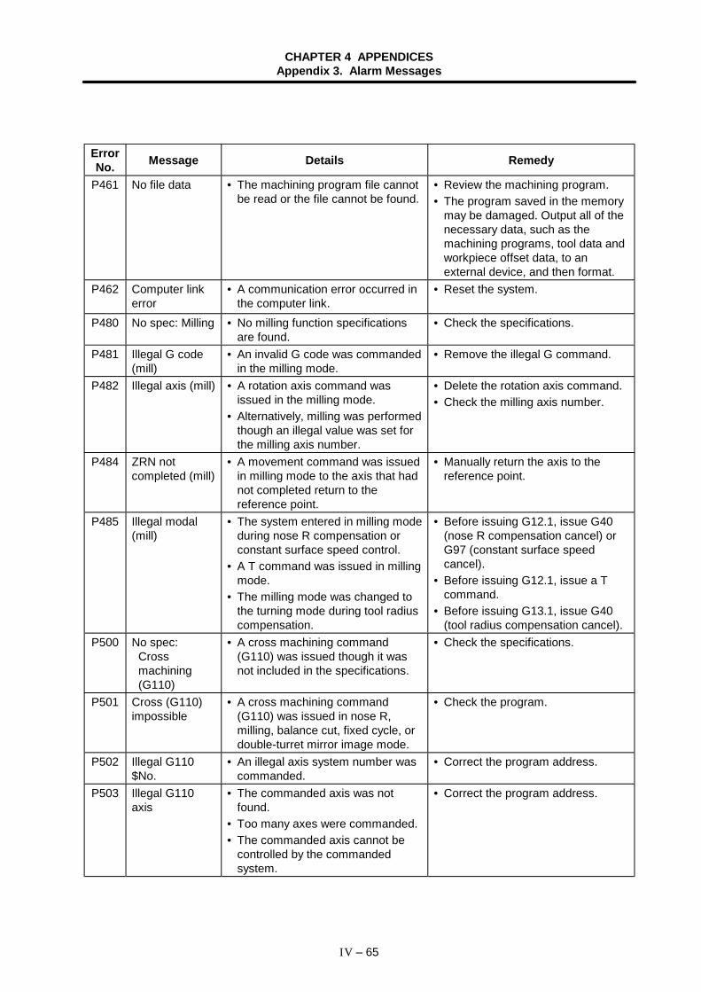
CHAPTER 4 APPENDICESAppendix 3. Alarm Messages
IV – 65
ErrorNo. Message Details Remedy
P461 No file data • The machining program file cannotbe read or the file cannot be found.
• Review the machining program.• The program saved in the memory
may be damaged. Output all of thenecessary data, such as themachining programs, tool data andworkpiece offset data, to anexternal device, and then format.
P462 Computer linkerror
• A communication error occurred inthe computer link.
• Reset the system.
P480 No spec: Milling • No milling function specificationsare found.
• Check the specifications.
P481 Illegal G code(mill)
• An invalid G code was commandedin the milling mode.
• Remove the illegal G command.
P482 Illegal axis (mill) • A rotation axis command wasissued in the milling mode.
• Alternatively, milling was performedthough an illegal value was set forthe milling axis number.
• Delete the rotation axis command.• Check the milling axis number.
P484 ZRN notcompleted (mill)
• A movement command was issuedin milling mode to the axis that hadnot completed return to thereference point.
• Manually return the axis to thereference point.
P485 Illegal modal(mill)
• The system entered in milling modeduring nose R compensation orconstant surface speed control.
• A T command was issued in millingmode.
• The milling mode was changed tothe turning mode during tool radiuscompensation.
• Before issuing G12.1, issue G40(nose R compensation cancel) orG97 (constant surface speedcancel).
• Before issuing G12.1, issue a Tcommand.
• Before issuing G13.1, issue G40(tool radius compensation cancel).
P500 No spec:Crossmachining(G110)
• A cross machining command(G110) was issued though it wasnot included in the specifications.
• Check the specifications.
P501 Cross (G110)impossible
• A cross machining command(G110) was issued in nose R,milling, balance cut, fixed cycle, ordouble-turret mirror image mode.
• Check the program.
P502 Illegal G110$No.
• An illegal axis system number wascommanded.
• Correct the program address.
P503 Illegal G110axis
• The commanded axis was notfound.
• Too many axes were commanded.• The commanded axis cannot be
controlled by the commandedsystem.
• Correct the program address.
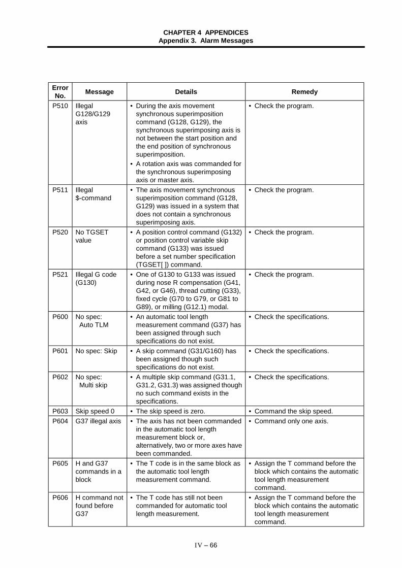
CHAPTER 4 APPENDICESAppendix 3. Alarm Messages
IV – 66
ErrorNo. Message Details Remedy
P510 IllegalG128/G129axis
• During the axis movementsynchronous superimpositioncommand (G128, G129), thesynchronous superimposing axis isnot between the start position andthe end position of synchronoussuperimposition.
• A rotation axis was commanded forthe synchronous superimposingaxis or master axis.
• Check the program.
P511 Illegal$-command
• The axis movement synchronoussuperimposition command (G128,G129) was issued in a system thatdoes not contain a synchronoussuperimposing axis.
• Check the program.
P520 No TGSETvalue
• A position control command (G132)or position control variable skipcommand (G133) was issuedbefore a set number specification(TGSET[ ]) command.
• Check the program.
P521 Illegal G code(G130)
• One of G130 to G133 was issuedduring nose R compensation (G41,G42, or G46), thread cutting (G33),fixed cycle (G70 to G79, or G81 toG89), or milling (G12.1) modal.
• Check the program.
P600 No spec:Auto TLM
• An automatic tool lengthmeasurement command (G37) hasbeen assigned through suchspecifications do not exist.
• Check the specifications.
P601 No spec: Skip • A skip command (G31/G160) hasbeen assigned though suchspecifications do not exist.
• Check the specifications.
P602 No spec:Multi skip
• A multiple skip command (G31.1,G31.2, G31.3) was assigned thoughno such command exists in thespecifications.
• Check the specifications.
P603 Skip speed 0 • The skip speed is zero. • Command the skip speed.P604 G37 illegal axis • The axis has not been commanded
in the automatic tool lengthmeasurement block or,alternatively, two or more axes havebeen commanded.
• Command only one axis.
P605 H and G37commands in ablock
• The T code is in the same block asthe automatic tool lengthmeasurement command.
• Assign the T command before theblock which contains the automatictool length measurementcommand.
P606 H command notfound beforeG37
• The T code has still not beencommanded for automatic toollength measurement.
• Assign the T command before theblock which contains the automatictool length measurementcommand.
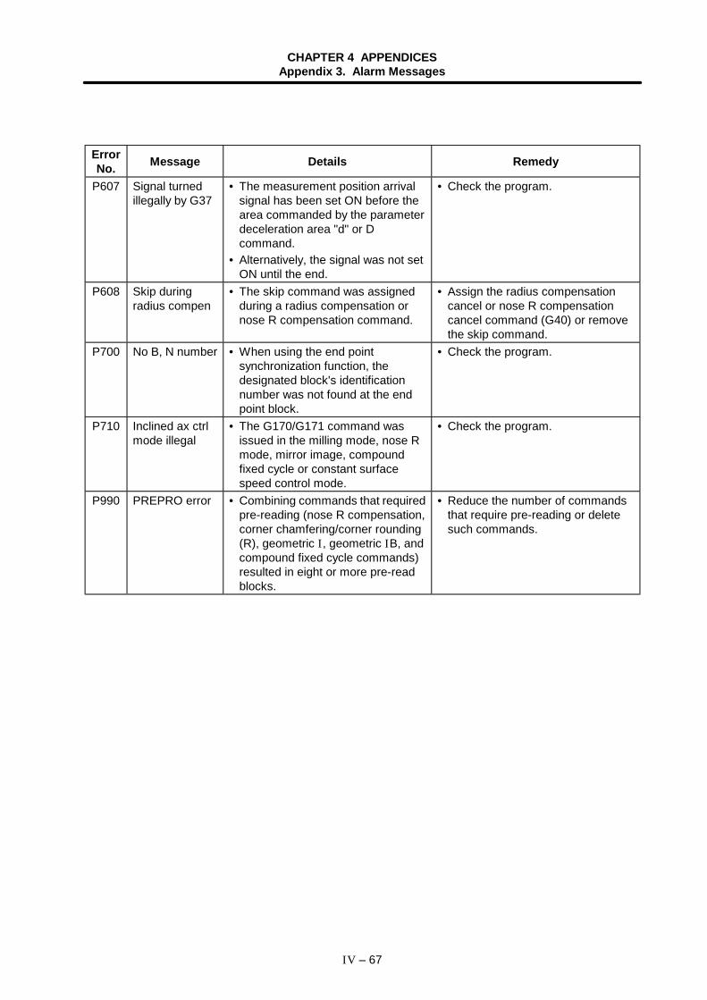
CHAPTER 4 APPENDICESAppendix 3. Alarm Messages
IV – 67
ErrorNo. Message Details Remedy
P607 Signal turnedillegally by G37
• The measurement position arrivalsignal has been set ON before thearea commanded by the parameterdeceleration area "d" or Dcommand.
• Alternatively, the signal was not setON until the end.
• Check the program.
P608 Skip duringradius compen
• The skip command was assignedduring a radius compensation ornose R compensation command.
• Assign the radius compensationcancel or nose R compensationcancel command (G40) or removethe skip command.
P700 No B, N number • When using the end pointsynchronization function, thedesignated block's identificationnumber was not found at the endpoint block.
• Check the program.
P710 Inclined ax ctrlmode illegal
• The G170/G171 command wasissued in the milling mode, nose Rmode, mirror image, compoundfixed cycle or constant surfacespeed control mode.
• Check the program.
P990 PREPRO error • Combining commands that requiredpre-reading (nose R compensation,corner chamfering/corner rounding(R), geometric I, geometric IB, andcompound fixed cycle commands)resulted in eight or more pre-readblocks.
• Reduce the number of commandsthat require pre-reading or deletesuch commands.

Revision History
Sub-No. Date of revision Revision details
A October, 2000 First edition created.

NoticeEvery effort has been made to keep up with software and hardware revisions in thecontents described in this manual. However, please understand that in someunavoidable cases simultaneous revision is not possible.Please contact your Mitsubishi Electric dealer with any questions or commentsregarding the use of this product.
Duplication ProhibitedThis instruction manual may not be reproduced in any form, in part or in whole,without written permission from Mitsubishi Electric Corporation.
2000 MITSUBISHI ELECTRIC CORPORATION
ALL RIGHTS RESERVED.

MITSUBISHI ELECTRIC CORPORATIONHEAD OFFICE: MITSUBISHI DENKI BLD. MARUNOUCHI. TOKYO 100-0005 TEL:03-218-3426
Printed in Japan Specifications subject to change without notice.