Embed Size (px)
Citation preview
Design Manual for Roads and Bridges
DrainageDesign
CD 534Chamber tops and gully tops for road drainageand services(formerly HA 104/09, IAN 196/17, IAN 197/17)
Revision 0
SummaryThis document contains the requirements for road chamber top and gully top installations onmotorway and all-purpose trunk roads.
Application by Overseeing OrganisationsAny specific requirements for Overseeing Organisations alternative or supplementary to those given in this documentare given in National Application Annexes to this document.
Feedback and EnquiriesUsers of this document are encouraged to raise any enquiries and/or provide feedback on the content and usageof this document to the dedicated Highways England team. The email address for all enquiries and feedback is:[email protected]
This is a controlled document.
CD 534 Revision 0 Contents
Contents
Release notes 2
Foreword 3Publishing information . . . . . . . . . . . . . . . . . . . . . . . . . . . . . . . . . . . . . . . . . . . . . . . . 3Contractual and legal considerations . . . . . . . . . . . . . . . . . . . . . . . . . . . . . . . . . . . . . . . . 3
Introduction 4Background . . . . . . . . . . . . . . . . . . . . . . . . . . . . . . . . . . . . . . . . . . . . . . . . . . . . . . 4Assumptions made in the preparation of this document . . . . . . . . . . . . . . . . . . . . . . . . . . . . . 4Mutual Recognition . . . . . . . . . . . . . . . . . . . . . . . . . . . . . . . . . . . . . . . . . . . . . . . . . 4
Abbreviations 5
Terms and definitions 6
1. Scope 7Aspects covered . . . . . . . . . . . . . . . . . . . . . . . . . . . . . . . . . . . . . . . . . . . . . . . . . . . 7Implementation . . . . . . . . . . . . . . . . . . . . . . . . . . . . . . . . . . . . . . . . . . . . . . . . . . . 7Health and safety . . . . . . . . . . . . . . . . . . . . . . . . . . . . . . . . . . . . . . . . . . . . . . . . . . . 7Use of GG 101 . . . . . . . . . . . . . . . . . . . . . . . . . . . . . . . . . . . . . . . . . . . . . . . . . . . . 7
2. Design for chamber tops and gully tops 8General . . . . . . . . . . . . . . . . . . . . . . . . . . . . . . . . . . . . . . . . . . . . . . . . . . . . . . . . 8Chamber tops . . . . . . . . . . . . . . . . . . . . . . . . . . . . . . . . . . . . . . . . . . . . . . . . . . . . 8Gully tops . . . . . . . . . . . . . . . . . . . . . . . . . . . . . . . . . . . . . . . . . . . . . . . . . . . . . . . 9
3. Dealing with situations where existing chamber tops can be located in the existing carriageway 10Existing chamber tops becoming located in the carriageway . . . . . . . . . . . . . . . . . . . . . . . . . . . 10
Requirements . . . . . . . . . . . . . . . . . . . . . . . . . . . . . . . . . . . . . . . . . . . . . . . . . . 10Assessment of locations and programme of upgrading works . . . . . . . . . . . . . . . . . . . . . . . 10Decision tree for treatment of existing chambers that are or may become located in the carriageway. . 10
4. Normative references 11
5. Informative references 12
Appendix A. WRc skid test 13A1 Test procedure . . . . . . . . . . . . . . . . . . . . . . . . . . . . . . . . . . . . . . . . . . . . . . . . . . 13A2 Verification . . . . . . . . . . . . . . . . . . . . . . . . . . . . . . . . . . . . . . . . . . . . . . . . . . . . 13
Appendix B. Decision tree 14
Notification 16
1

CD 534 Revision 0 Release notes
Release notesVersion Date Details of amendments0 Feb 2020 CD 534 replaces HA 104/09. This full document has been re-written to make it
compliant with the new Highways England drafting rules. The document alsoincorporates the guidance contained in IAN 196/17 and IAN 197/17.
2

CD 534 Revision 0 Foreword
Foreword
Publishing informationThis document is published by Highways England.
This document supersedes HA 104/09, IAN 196/17 and IAN 197/17 which are withdrawn.
Contractual and legal considerationsThis document forms part of the works specification. It does not purport to include all the necessaryprovisions of a contract. Users are responsible for applying all appropriate documents applicable totheir contract.
3
CD 534 Revision 0 Introduction
Introduction
BackgroundThis document sets out the requirements for chamber tops and gully tops on motorway and all-purposetrunk roads. This document may be read in conjunction with the RSTA ADEPT Code of Practice forIronwork Systems Installation and Refurbishment [Ref 3.I].
To reduce the risks to both road users and maintenance staff, chamber tops are no longer permittedwithin the carriageway of new construction and the need for existing chamber tops in the carriagewayshould be assessed. By removing or reducing the number of chamber tops in the carriageway, thisreduces the need for lane closures and traffic management when carrying out routine inspection andmaintenance tasks.
The premature failure of chamber top and gully top installations as well as the failure of the chamberitself and surrounding pavement surface can pose a risk to both maintenance operatives and roadusers.
Assumptions made in the preparation of this documentThe assumptions made in GG 101 [Ref 4.N] apply to this document.
Mutual RecognitionWhere there is a requirement in this document for compliance with any part of a "British Standard", orother technical specification, that requirement may be met by compliance with GG 101 [Ref 4.N].
4
CD 534 Revision 0 Abbreviations
Abbreviations
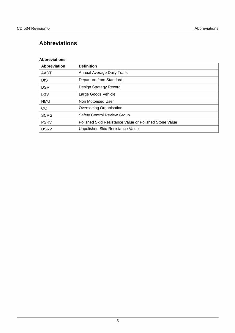
AbbreviationsAbbreviation Definition
AADT Annual Average Daily Traffic
DfS Departure from Standard
DSR Design Strategy Record
LGV Large Goods Vehicle
NMU Non Motorised User
OO Overseeing Organisation
SCRG Safety Control Review Group
PSRV Polished Skid Resistance Value or Polished Stone Value
USRV Unpolished Skid Resistance Value
5
CD 534 Revision 0 Terms and definitions
Terms and definitions
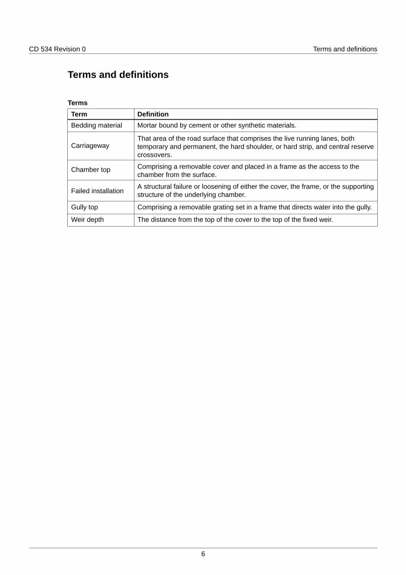
TermsTerm DefinitionBedding material Mortar bound by cement or other synthetic materials.
CarriagewayThat area of the road surface that comprises the live running lanes, bothtemporary and permanent, the hard shoulder, or hard strip, and central reservecrossovers.
Chamber top Comprising a removable cover and placed in a frame as the access to thechamber from the surface.
Failed installationA structural failure or loosening of either the cover, the frame, or the supportingstructure of the underlying chamber.
Gully top Comprising a removable grating set in a frame that directs water into the gully.
Weir depth The distance from the top of the cover to the top of the fixed weir.
6
CD 534 Revision 0 1. Scope
1. Scope
Aspects covered1.1 The requirements contained in this document shall be applied to road chamber top and gully top
installations on motorway and all-purpose trunk roads.
1.2 Chamber tops in carriageways including hardstrips, hard shoulders and central reserve crossovers ofmotorways and all-purpose trunk roads shall not be permitted.
1.3 Where existing (legacy) chambers are located in the running lanes then the decision tree, shown asFigure 1 of Appendix B, shall be used to resolve the presence of that chamber in the running lane.
Implementation1.4 This document shall be implemented forthwith on all schemes involving the use of chamber tops and
gully tops for road drainage on the Overseeing Organisation's motorway and all-purpose trunk roadsaccording to the implementation requirements of GG 101 [Ref 4.N].
Health and safety1.5 Safety risk mitigation measures shall follow the ERIC hierarchy - eliminate, reduce, isolate and control
for each identified safety risk.
Use of GG 1011.6 The requirements contained in GG 101 [Ref 4.N] shall be followed in respect of activities covered by
this document.
7
CD 534 Revision 0 2. Design for chamber tops and gully tops
2. Design for chamber tops and gully tops
General2.1 New chamber tops shall not be installed in carriageways including hardstrips, hard shoulders and
central reserve crossovers of motorways and all-purpose trunk roads.
2.2 Chamber tops and gully tops shall be specified in accordance with BS EN 124 [Ref 3.N] and therequirements of this document.
2.3 Chamber tops with clear opening of greater than 1m shall be in accordance with BS 9124 [Ref 11.N]and the requirements of this document.
2.4 The minimum classification for all chamber tops and gully tops installed in areas of motorways andall-purpose trunk roads that are at risk from trafficking, either directly or indirectly, shall be of gradeD400 in accordance with BS EN 124 [Ref 3.N].
2.5 Where the AADT LGV for a carriageway exceeds 1500 in each direction, grade E600 chamber topsshall be specified.
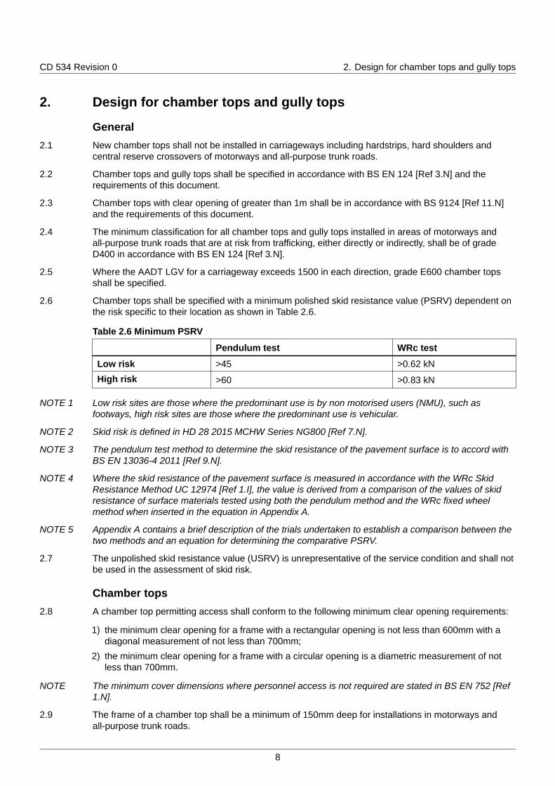
2.6 Chamber tops shall be specified with a minimum polished skid resistance value (PSRV) dependent onthe risk specific to their location as shown in Table 2.6.
Table 2.6 Minimum PSRV
Pendulum test WRc test
Low risk >45 >0.62 kN
High risk >60 >0.83 kN
NOTE 1 Low risk sites are those where the predominant use is by non motorised users (NMU), such asfootways, high risk sites are those where the predominant use is vehicular.
NOTE 2 Skid risk is defined in HD 28 2015 MCHW Series NG800 [Ref 7.N].
NOTE 3 The pendulum test method to determine the skid resistance of the pavement surface is to accord withBS EN 13036-4 2011 [Ref 9.N].
NOTE 4 Where the skid resistance of the pavement surface is measured in accordance with the WRc SkidResistance Method UC 12974 [Ref 1.I], the value is derived from a comparison of the values of skidresistance of surface materials tested using both the pendulum method and the WRc fixed wheelmethod when inserted in the equation in Appendix A.
NOTE 5 Appendix A contains a brief description of the trials undertaken to establish a comparison between thetwo methods and an equation for determining the comparative PSRV.
2.7 The unpolished skid resistance value (USRV) is unrepresentative of the service condition and shall notbe used in the assessment of skid risk.
Chamber tops2.8 A chamber top permitting access shall conform to the following minimum clear opening requirements:
1) the minimum clear opening for a frame with a rectangular opening is not less than 600mm with adiagonal measurement of not less than 700mm;
2) the minimum clear opening for a frame with a circular opening is a diametric measurement of notless than 700mm.
NOTE The minimum cover dimensions where personnel access is not required are stated in BS EN 752 [Ref1.N].
2.9 The frame of a chamber top shall be a minimum of 150mm deep for installations in motorways andall-purpose trunk roads.
8
CD 534 Revision 0 2. Design for chamber tops and gully tops
2.10 The depth of the insertion of the chamber top cover within the frame shall be no less than 50mm, or noless than 80mm if the design relies upon the depth of insertion for security.
2.11 Types of loose couplings, other than those specified in MCHW Series 500 [Ref 5.N] shall be specifiedas having a minimum cross-sectional area of 140mm2.
Gully tops2.12 Gully tops (frame and grating) shall be specified as grade D400 in accordance with BS EN 124 [Ref
3.N].
2.12.1 Hinged gratings may be either kerb hinged or side hinged appropriate to the direction of traffic.
2.12.2 Kerb-type gully gratings and frames should provide a kerbside water intake and an access which, ifhinged, opens away from the carriageway i.e. towards the kerb.
2.12.3 Weir depth, if any, should be 115mm (Type 1) or 165mm (Type 2) as defined by BS 7903 [Ref 2.N].
2.12.4 Kerb-type gully gratings and frames should be provided with a Type HB (half batter) profile inaccordance with to BS 7263-1 [Ref 8.N] unless otherwise specified.
2.13 The critical dimensions of kerb-type gully gratings and frames shall be specified in accordance with BS7903 [Ref 2.N].
2.14 Nominal widths of gratings and minimum areas of waterway shall be specified in accordance with BSEN 124 [Ref 3.N] and BS 7903 [Ref 2.N].
2.14.1 The minimum area of waterway should be 900 cm2.
2.14.2 There should be a minimum waterway area of 45 cm2 between the kerb face of the frame and a parallelline 50mm distant.
2.14.3 There should be a minimum waterway area of 65 cm2 between the kerb face of the frame and a parallelline 90 mm distant.
2.15 The gully top frame shall be at least 100 mm deep.
2.16 Kerb type gully covers and frames shall be specified with:
1) a metal retaining bar, of minimum cross section 35 mm x 25 mm for use during construction;
2) a cover with either open keyway(s) or a locking mechanism;
3) an opening unit with a minimum rectangular clear opening of 400 mm x 250 mm;
4) a locking mechanism where a cover can be readily raised without the use of the key or tool;
5) hinges at the rear edge of the cover, as viewed from the road, where used;
6) a raised pattern conforming with BS EN 124 [Ref 3.N] and be self draining;
7) a grid with horizontal bars of a minimum of 12 mm galvanised in accordance with BS EN ISO 1461[Ref 10.N] or a minimum of two integrally cast vertical fins to act as a debris trap across the openmouth of the unit.
9
CD 534 Revision 0 3. Dealing with situations where existing chambe...
3. Dealing with situations where existing chamber tops can belocated in the existing carriageway
Existing chamber tops becoming located in the carriageway3.1 The requirements in this section shall be applied to smart motorways, in particular, but also to all:
1) schemes currently in design or under construction and future schemes where hard shoulders are tobe converted to running lanes;
2) temporary road works where the hard shoulder is to be utilised as a running lane.
3.2 The treatment of an existing chamber top in the carriageway shall be determined in accordance withthe decision tree shown as Figure 1 in Appendix B.
Requirements
3.3 Existing chamber tops positioned within the carriageway shall be removed.
NOTE There have been a number of failures of chamber top covers where the hard shoulder has beenconverted to, or utilised as, a running lane. Similar failures have occurred where the hard shoulder isutilised as a running lane in roadworks.
3.4 Any decisions (including plating over) for chamber tops to be located in conflict points of merge ordiverge shall be endorsed by the Safety Control Review Group (SCRG) and the decision processrecorded in the design strategy record (DSR).
3.5 Chambers that have been plated over shall be recorded in accordance with the OverseeingOrganisation's data requirements, including details of the depth of the plating.
3.6 Where any re-alignment is undertaken or chambers in the verge introduced – the connecting pipingshall be the same diameter to that of the main drain with an invert to invert connection that will facilitateCCTV access.
3.7 Where any re-alignment is undertaken or chambers in the verge introduced - the chambers shall bebenched to the invert level of the connecting pipe.
Assessment of locations and programme of upgrading works
3.8 Sites affected by locating a chamber access in the carriageway shall be identified and recorded.
Decision tree for treatment of existing chambers that are or may become located in thecarriageway.
3.9 Where an existing chamber in the carriageway is to be retained and/or modified by a scheme then thedecision tree, in Appendix B, shall be followed.
NOTE E600 chamber tops are not an alternative to addressing the location of chamber tops in running lanes.
3.10 Chamber tops shall not be permitted within the wheel track zone.
3.10.1 Where a chamber is identified as existing in the carriageway pavement, the local network should besurveyed for the presence of similarly located chambers.
3.11 All drainage details shall be recorded in accordance with the Overseeing Organisation's datarequirements, including chamber realignments, treatments of plating over, piping through, sidechambers.
10
CD 534 Revision 0 4. Normative references
4. Normative referencesThe following documents, in whole or in part, are normative references for this document and areindispensable for its application. For dated references, only the edition cited applies. For undatedreferences, the latest edition of the referenced document (including any amendments) applies.
Ref 1.N BSI. BS EN 752, 'Drain and sewer systems outside buildings - sewer systemmanagement.'
Ref 2.N BSI. BS 7903, 'Guide to selection and use of gully tops and manhole covers forinstallation within the highway'
Ref 3.N BSI. BS EN 124, 'Gully tops and manhole tops for vehicular and pedestrian areas.Definitions, classification, general principles of design, performance requirements andtest methods'
Ref 4.N Highways England. GG 101, 'Introduction to the Design Manual for Roads andBridges'
Ref 5.N Highways England. MCHW Series 500, 'Manual of Contract Documents for HighwayWorks, Volume 1 Specification for Highway Works. Series 500 Drainage and serviceducts.'
Ref 6.N Highways England. MCHW Series 900, 'Manual of Contract Documents for HighwayWorks. Volume 1 Specification for Highway Works. Series 900 Road Pavements –Bituminous Bound Materials.'
Ref 7.N Highways England. MCHW Series NG800, 'Notes for guidance on the specificationfor highway works (MCHW2)'
Ref 8.N BSI. BS 7263-1, 'Precast concrete flags, kerbs, channels,edgings and quadrants'
Ref 9.N BSI. BS EN 13036-4, 'Road and airfield surface characteristics. Test methods. Part 4-Method for measurement of slip/skid resistance of a surface: The pendulum test' ,2011
Ref 10.N BSI. BS EN ISO 1461, 'Specification for hot dip galvanized coatings on iron and steelarticles'
Ref 11.N BSI. BS 9124, 'Specification for Steel and Aluminium Access Covers Systems with1m Clear Opening'
11
CD 534 Revision 0 5. Informative references
5. Informative referencesThe following documents are informative references for this document and provide supportinginformation.
Ref 1.I WRc. UC 12974, 'Comparison of Skid Resistance Test Methods for Manhole Covers'
Ref 2.I BSI. DD ENV 12633, 'Method of determination of unpolished and polished slip/skidresistance value'
Ref 3.I RSTA. 'RSTA ADEPT Code of practice for ironwork systems installation andrefurbishment'
Ref 4.I American Society for Testing Materials. ASTM E1884, 'Standard specification for Asize 10x4-5 smooth tread friction test tire'
12
CD 534 Revision 0 Appendix A. WRc skid test
Appendix A. WRc skid test
A1 Test procedureThe skid resistance of pavement surface materials is measured using the Pendulum Test in accordancewith Annex B of DD ENV 12633 [Ref 2.I]. This is inappropriate for adequately assessing the skidresistance of profiled surfaces such as those formed on chamber top covers.
WRc were commissioned in 2016 to devise a more appropriate test method for these raised surfaceprofiles and developed the locked wheel test described in their final report UC 12974 [Ref 1.I] ofFebruary 2018 and summarised below.
The test is undertaken using a rig comprising of a support frame with a top to support the test sample.A fixed wheel with a specific smooth tread tyre ASTM E1884 [Ref 4.I], and inflated to 40 psi, is mountedin a free moving frame. The tyre is placed on the test sample and a load of 70kg is applied to thewheel. The tyre is than drawn across the sample surface by means of a hand crank. The link betweenthe handle and the wheel contains a load cell that measures the Peak Force (in kN) which is displayedon a force meter.
The test sample is thoroughly wetted prior to carrying out each test.
A2 VerificationA range of materials and chamber tops were subject to skid resistance tests using both the pendulumtest and the fixed wheel test.
The values obtained by each method were then compared to derive a formula that would enable adirect comparison to be made.
The comparative formula is:
y = 2 + 70x
where x is the skid wheel peak force (in kN) and y is the polished skid resistance value measured usingthe pendulum test.
13
CD 534 Revision 0 Appendix B. Decision tree
Appendix B. Decision tree
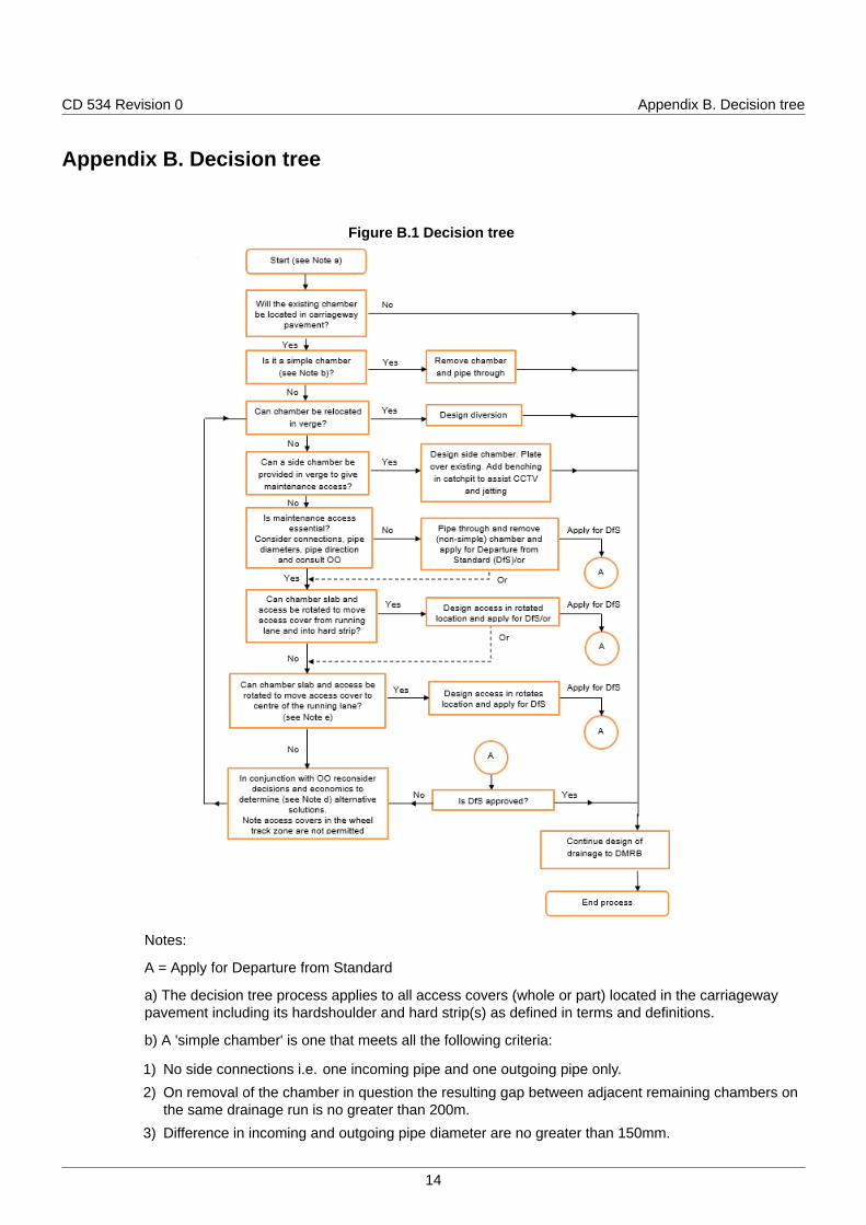
Figure B.1 Decision tree
Notes:
A = Apply for Departure from Standard
a) The decision tree process applies to all access covers (whole or part) located in the carriagewaypavement including its hardshoulder and hard strip(s) as defined in terms and definitions.
b) A 'simple chamber' is one that meets all the following criteria:
1) No side connections i.e. one incoming pipe and one outgoing pipe only.
2) On removal of the chamber in question the resulting gap between adjacent remaining chambers onthe same drainage run is no greater than 200m.
3) Difference in incoming and outgoing pipe diameter are no greater than 150mm.
14
CD 534 Revision 0 Appendix B. Decision tree
4) The change in pipe direction is no greater than 22.5°.
c) In central reserves the full area of emergency crossover points are included even where a reducedpavement structure is provided; but excluded are other hardened central reserve areas that do nothave the full depth pavement construction of the adjacent carriageway.
d) The Overseeing Organisation will discuss alternative solutions to achieve a consensus prior to thesubmission of a DfS. The alternatives include:
1) a plated & buried chamber retained under the pavement around bridge piers where existing changesof direction provide pipe angles >22.5 degrees; and
2) a retained buried benched chamber within the central reserve, but with rodding eye for jettingpurposes.
e) Where reference is made to a location wholly between the wheel track zones within a running lane,additionally the area between the wheel track zone and the carriageway edge line and its hard strip isan equivalent area. For the purposes of this decision tree, the wheel track zone is a 900mm wide zone(and not 600mm wide zone). If retaining an access cover within the entry and exit areas of junctions(both main line and slip road) as the combined, and individually wider, wheel track zones are not assimple as that described in MCHW Series 900 [Ref 6.N].
15

CD 534 Revision 0 Notification
NotificationThis document was notified in draft to the European Commission in accordance with TechnicalStandards and Regulations Directive 2015/1535/EU.
16

© Crown copyright 2020.You may re-use this information (not including logos) free of charge in any format or medium, under the terms of the
Open Government Licence. To view this licence:visit www.nationalarchives.gov.uk/doc/open-government-licence/,
write to the Information Policy Team, The National Archives, Kew, London TW9 4DU,or email [email protected].
Design Manual for Roads and Bridges
DrainageDesign
CD 534England National Application Annex to CD 534Chamber tops and gully tops for road drainageand services(formerly HA 104/09, IAN 196/17, IAN 197/17)
Revision 0
SummaryThis National Application Annex sets out the Highways England-specific requirements relating tochamber tops and gully tops.
Feedback and EnquiriesUsers of this document are encouraged to raise any enquiries and/or provide feedback on the content and usageof this document to the dedicated Highways England team. The email address for all enquiries and feedback is:[email protected]
This is a controlled document.
CD 534 Revision 0 Contents
Contents
Release notes 2
Foreword 3Publishing information . . . . . . . . . . . . . . . . . . . . . . . . . . . . . . . . . . . . . . . . . . . . . . . . 3Contractual and legal considerations . . . . . . . . . . . . . . . . . . . . . . . . . . . . . . . . . . . . . . . . 3
Introduction 4Background . . . . . . . . . . . . . . . . . . . . . . . . . . . . . . . . . . . . . . . . . . . . . . . . . . . . . . 4Assumptions made in the preparation of this document . . . . . . . . . . . . . . . . . . . . . . . . . . . . . 4
Terms and definitions 5
E/1. Existing chamber access covers becoming located in the carriageway 6
E/2. Assessment/Upgrading works for chamber tops located in a running lane 7
E/3. Normative references 8
E/4. Informative references 9
1

CD 534 Revision 0 Release notes
Release notesVersion Date Details of amendments0 Feb 2020 Highways England National Application Annex to CD 534.
2

CD 534 Revision 0 Foreword
Foreword
Publishing informationThis document is published by Highways England.
This document supersedes HA 104/09, IAN 196/17 and IAN 197/17 which are withdrawn.
Contractual and legal considerationsThis document forms part of the works specification. It does not purport to include all the necessaryprovisions of a contract. Users are responsible for applying all appropriate documents applicable totheir contract.
3

CD 534 Revision 0 Introduction
Introduction
BackgroundThis National Application Annex gives the Highways England-specific requirements relating to chambertops and gully tops.
Assumptions made in the preparation of this documentThe assumptions made in GG 101 [Ref 1.N] apply to this document.
4
CD 534 Revision 0 Terms and definitions
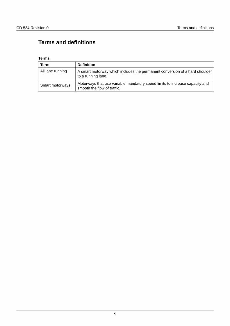
Terms and definitions
TermsTerm DefinitionAll lane running A smart motorway which includes the permanent conversion of a hard shoulder
to a running lane.
Smart motorways Motorways that use variable mandatory speed limits to increase capacity andsmooth the flow of traffic.
5
CD 534 Revision 0 E/1. Existing chamber access covers becoming locat...
E/1. Existing chamber access covers becoming located in thecarriageway
E/1.1 The requirements of CD 534 section 3 shall be applied to all smart motorways.
6
CD 534 Revision 0 E/2. Assessment/Upgrading works for chamber tops l...
E/2. Assessment/Upgrading works for chamber tops located in arunning lane
E/2.1 The requirements of CD 534 section 3 shall be applied retrospectively to all existing chamber accessesin live running lanes in operational smart motorway - all lane running or part time (dynamic hardshoulder running) schemes and any other motorways that are managed by Highways England.
E/2.2 Where a requirement in CD 534 cannot be followed, the departure process outlined in GG 101 [Ref1.N] shall be followed before an application can be made to certify a design under the certification ofdrainage design process in CG 502 [Ref 1.I].
7

CD 534 Revision 0 E/3. Normative references
E/3. Normative referencesThe following documents, in whole or in part, are normative references for this document and areindispensable for its application. For dated references, only the edition cited applies. For undatedreferences, the latest edition of the referenced document (including any amendments) applies.
Ref 1.N Highways England. GG 101, 'Introduction to the Design Manual for Roads andBridges'
8

CD 534 Revision 0 E/4. Informative references
E/4. Informative referencesThe following documents are informative references for this document and provide supportinginformation.
Ref 1.I Highways England. CG 502, 'The certification of drainage design'
9

© Crown copyright 2020.You may re-use this information (not including logos) free of charge in any format or medium, under the terms of the
Open Government Licence. To view this licence:visit www.nationalarchives.gov.uk/doc/open-government-licence/,
write to the Information Policy Team, The National Archives, Kew, London TW9 4DU,or email [email protected].
Design Manual for Roads and Bridges
DrainageDesign
CD 534Northern Ireland National Application Annex toCD 534 Chamber tops and gully tops for roaddrainage and services(formerly HA 104/09, IAN 196/17, IAN 197/17)
Revision 0
SummaryThere are no specific requirements for Department for Infrastructure, Northern Irelandsupplementary or alternative to those given in CD 534.
Feedback and EnquiriesUsers of this document are encouraged to raise any enquiries and/or provide feedback on the content and usage ofthis document to the dedicated team in the Department for Infrastructure, Northern Ireland. The email address for allenquiries and feedback is: [email protected]
This is a controlled document.

CD 534 Revision 0 Contents
Contents
Release notes 2
1

CD 534 Revision 0 Release notes
Release notesVersion Date Details of amendments0 Feb 2020 Department for Infrastructure Northern Ireland National Application Annex to
CD 534.
2

© Crown copyright 2020.You may re-use this information (not including logos) free of charge in any format or medium, under the terms of the
Open Government Licence. To view this licence:visit www.nationalarchives.gov.uk/doc/open-government-licence/,
write to the Information Policy Team, The National Archives, Kew, London TW9 4DU,or email [email protected].
Design Manual for Roads and Bridges
DrainageDesign
CD 534Scotland National Application Annex to CD534 Chamber tops and gully tops for roaddrainage and services(formerly HA 104/09, IAN 196/17, IAN 197/17)
Revision 0
SummaryThere are no specific requirements for Transport Scotland supplementary or alternative to thosegiven in CD 534.
Feedback and EnquiriesUsers of this document are encouraged to raise any enquiries and/or provide feedback on the content and usageof this document to the dedicated Transport Scotland team. The email address for all enquiries and feedback is:[email protected]
This is a controlled document.

CD 534 Revision 0 Contents
Contents
Release notes 2
1

CD 534 Revision 0 Release notes
Release notesVersion Date Details of amendments0 Feb 2020 Transport Scotland National Application Annex to CD 534.
2

© Crown copyright 2020.You may re-use this information (not including logos) free of charge in any format or medium, under the terms of the
Open Government Licence. To view this licence:visit www.nationalarchives.gov.uk/doc/open-government-licence/,
write to the Information Policy Team, The National Archives, Kew, London TW9 4DU,or email [email protected].
Design Manual for Roads and Bridges
DrainageDesign
CD 534Wales National Application Annex to CD 534Chamber tops and gully tops for road drainageand services(formerly HA 104/09, IAN 196/17, IAN 197/17)
Revision 0
SummaryThere are no specific requirements for Welsh Government supplementary or alternative to thosegiven in CD 534.
Feedback and EnquiriesUsers of this document are encouraged to raise any enquiries and/or provide feedback on the content and usageof this document to the dedicated Welsh Government team. The email address for all enquiries and feedback is:[email protected]
This is a controlled document.

CD 534 Revision 0 Contents
Contents
Release notes 2
1

CD 534 Revision 0 Release notes
Release notesVersion Date Details of amendments0 Feb 2020 Welsh Government National Application Annex to CD 534.
2

© Crown copyright 2020.You may re-use this information (not including logos) free of charge in any format or medium, under the terms of the
Open Government Licence. To view this licence:visit www.nationalarchives.gov.uk/doc/open-government-licence/,
write to the Information Policy Team, The National Archives, Kew, London TW9 4DU,or email [email protected].