Embed Size (px)
Citation preview
CD - Use of Instrumentation in a Radiological Environment ASP2012 – July 31th, 2012 1
Use of Instrumentation in a Radiological Environment
Christine Darve
For the ASP2012
CD - Use of Instrumentation in a Radiological Environment ASP2012 – July 31th, 2012 2
Instrumentation IdentificationRequirements
Installation techniques
Radiological Environment
LHC measurements and Process
Headlines:
CD - Use of Instrumentation in a Radiological Environment ASP2012 – July 31th, 2012
Instrumentation
• “An instrument is a device that measures and/or regulates physical quantity/process variables such as flow, temperature, level, or pressure.
• Requirements:– Operating Range, excitation, Output signal, Size, Offset, – Stability, interchangeability, Ease of Use, Cost
– Resolution : what is the smallest detected change– Precision (reproducibility or stability): how close to the
measurement value?– Accuracy: Closest between the results of a measurement and the
true value.
– Effect on its environment
– Environmental compatibility:
3
• Robustness• Response time
• Magnetic field effects
• Radiation resistance• Electromagnetic noise
effect
CD - Use of Instrumentation in a Radiological Environment ASP2012 – July 31th, 2012
Instrumentation basic recommendations
• Don’t use more accuracy & precision than required
• Use commercially produced sensors whenever possible
• Mount sensors to provide an easy access for maintenance
• Install redundant sensors for critical devices in remote location
• Be sure to consider how to recalibrate sensors
• Once R&D is done, minimize number of sensors in series production
4
CD - Use of Instrumentation in a Radiological Environment ASP2012 – July 31th, 2012
Measurement of uncertainty, u
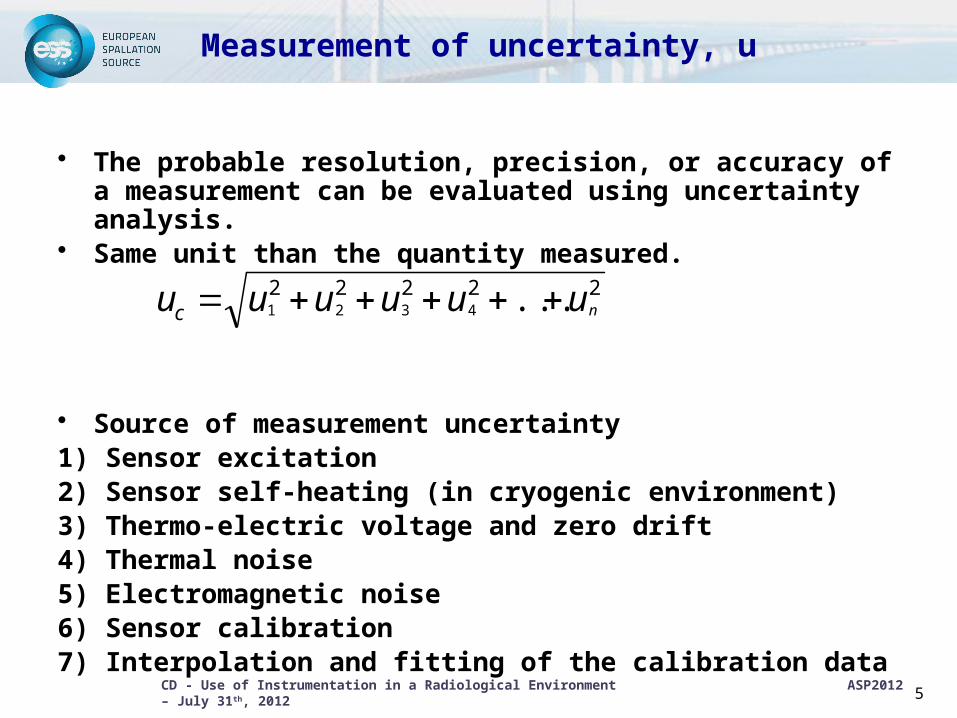
• The probable resolution, precision, or accuracy of a measurement can be evaluated using uncertainty analysis.
• Same unit than the quantity measured.
• Source of measurement uncertainty1) Sensor excitation2) Sensor self-heating (in cryogenic environment)3) Thermo-electric voltage and zero drift4) Thermal noise5) Electromagnetic noise6) Sensor calibration7) Interpolation and fitting of the calibration data
5
22222 ...4321 nuuuuuuc
CD - Use of Instrumentation in a Radiological Environment ASP2012 – July 31th, 2012
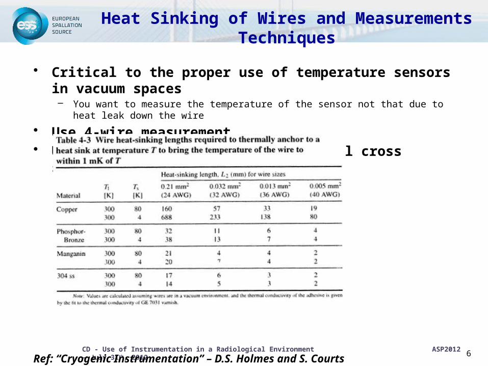
Heat Sinking of Wires and Measurements Techniques
• Critical to the proper use of temperature sensors in vacuum spaces– You want to measure the temperature of the sensor not that due to heat leak
down the wire
• Use 4-wire measurement• Use low conductivity wires with small cross sections
Ref: “Cryogenic Instrumentation” – D.S. Holmes and S. CourtsHandbook of Cryogenic Engineering 6
CD - Use of Instrumentation in a Radiological Environment ASP2012 – July 31th, 2012
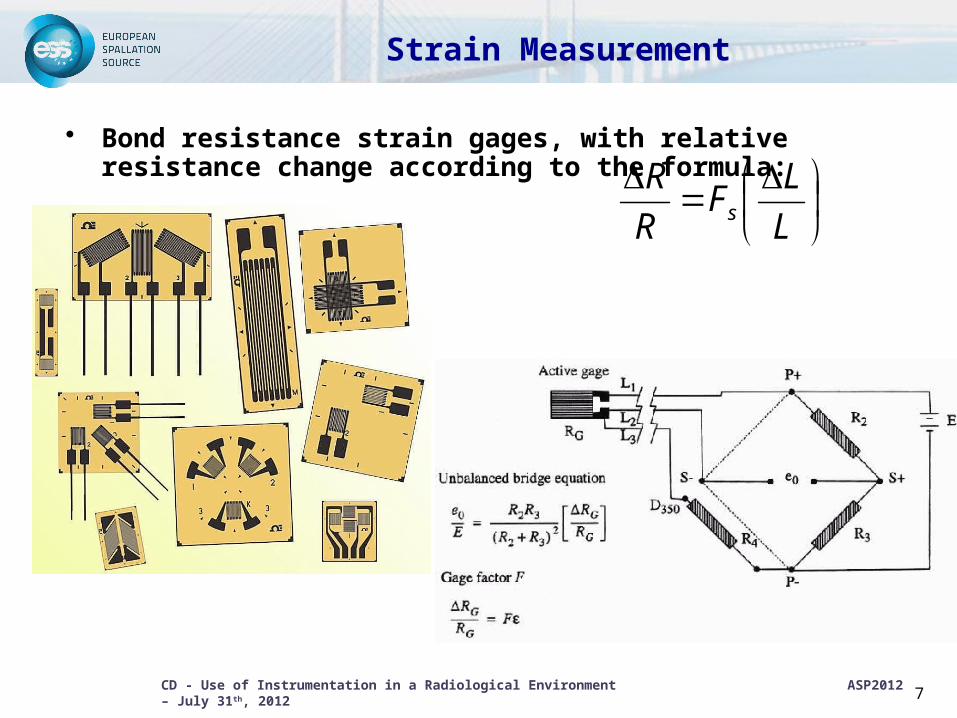
Strain Measurement
• Bond resistance strain gages, with relative resistance change according to the formula:
7
L
LF
R
Rs
CD - Use of Instrumentation in a Radiological Environment ASP2012 – July 31th, 2012
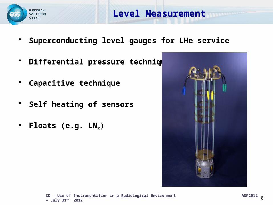
Level Measurement
• Superconducting level gauges for LHe service
• Differential pressure techniques
• Capacitive technique
• Self heating of sensors
• Floats (e.g. LN2)
8
CD - Use of Instrumentation in a Radiological Environment ASP2012 – July 31th, 2012
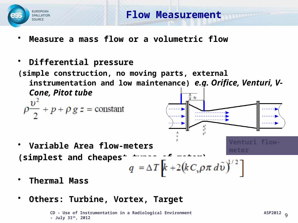
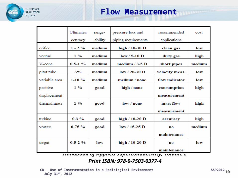
Flow Measurement
• Measure a mass flow or a volumetric flow
• Differential pressure(simple construction, no moving parts, external instrumentation
and low maintenance) e.g. Orifice, Venturi, V-Cone, Pitot tube
• Variable Area flow-meters(simplest and cheapest types of meter)
• Thermal Mass
• Others: Turbine, Vortex, Target
9
Venturi flow-meter
CD - Use of Instrumentation in a Radiological Environment ASP2012 – July 31th, 2012
Flow Measurement
Handbook of Applied Superconductivity, Volume 2Print ISBN: 978-0-7503-0377-4
10
CD - Use of Instrumentation in a Radiological Environment ASP2012 – July 31th, 2012
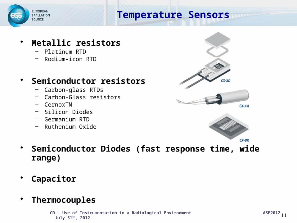
Temperature Sensors
• Metallic resistors– Platinum RTD– Rodium-iron RTD
• Semiconductor resistors– Carbon-glass RTDs– Carbon-Glass resistors– CernoxTM– Silicon Diodes– Germanium RTD– Ruthenium Oxide
• Semiconductor Diodes (fast response time, wide range)
• Capacitor
• Thermocouples
11
CD - Use of Instrumentation in a Radiological Environment ASP2012 – July 31th, 2012
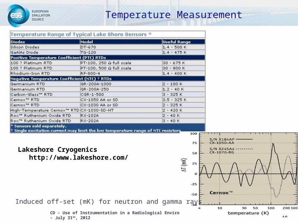
Temperature Measurement
Lakeshore Cryogenics http://www.lakeshore.com/
12
Induced off-set (mK) for neutron and gamma rays
CD - Use of Instrumentation in a Radiological Environment ASP2012 – July 31th, 2012
13
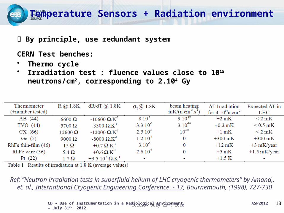
Temperature Sensors + Radiation environment
By principle, use redundant system
CERN Test benches:• Thermo cycle• Irradiation test : fluence values close to 1015 neutrons/cm2,
corresponding to 2.104 Gy
Ref: “Neutron irradiation tests in superfluid helium of LHC cryogenic thermometers” by Amand,, et. al., International Cryogenic Engineering Conference - 17, Bournemouth, (1998), 727-730
ICEC23- July 22nd, 2010
CD - Use of Instrumentation in a Radiological Environment ASP2012 – July 31th, 2012
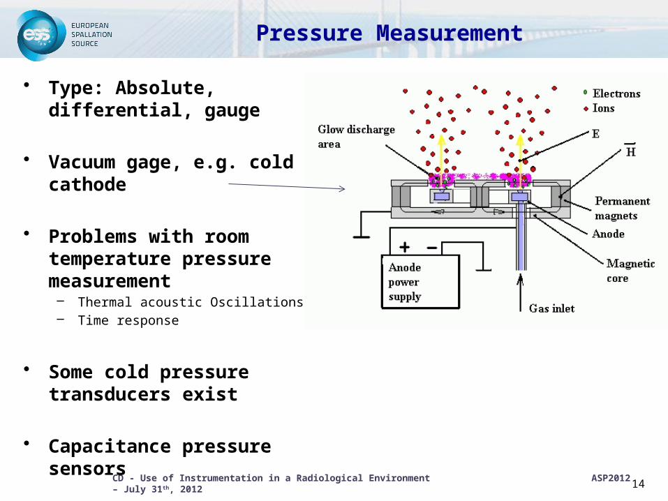
Pressure Measurement
• Type: Absolute, differential, gauge
• Vacuum gage, e.g. cold cathode
• Problems with room temperature pressure measurement– Thermal acoustic Oscillations– Time response
• Some cold pressure transducers exist
• Capacitance pressure sensors
14
CD - Use of Instrumentation in a Radiological Environment ASP2012 – July 31th, 2012
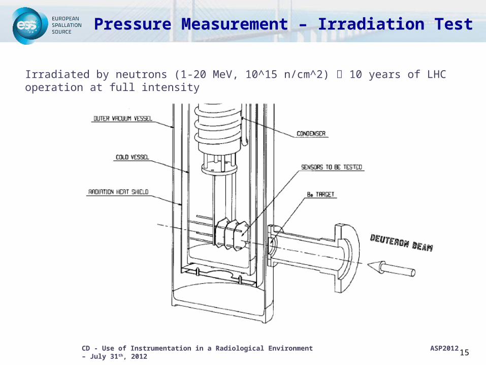
Pressure Measurement – Irradiation Test
15
Irradiated by neutrons (1-20 MeV, 10^15 n/cm^2) 10 years of LHC operation at full intensity
CD - Use of Instrumentation in a Radiological Environment ASP2012 – July 31th, 2012
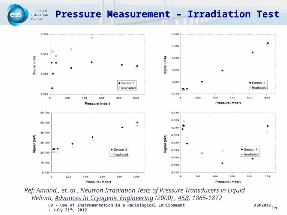
Pressure Measurement – Irradiation Test
16
Ref: Amand,, et. al., Neutron Irradiation Tests of Pressure Transducers in Liquid Helium, Advances In Cryogenic Engineering (2000) , 45B, 1865-1872
CD - Use of Instrumentation in a Radiological Environment ASP2012 – July 31th, 2012
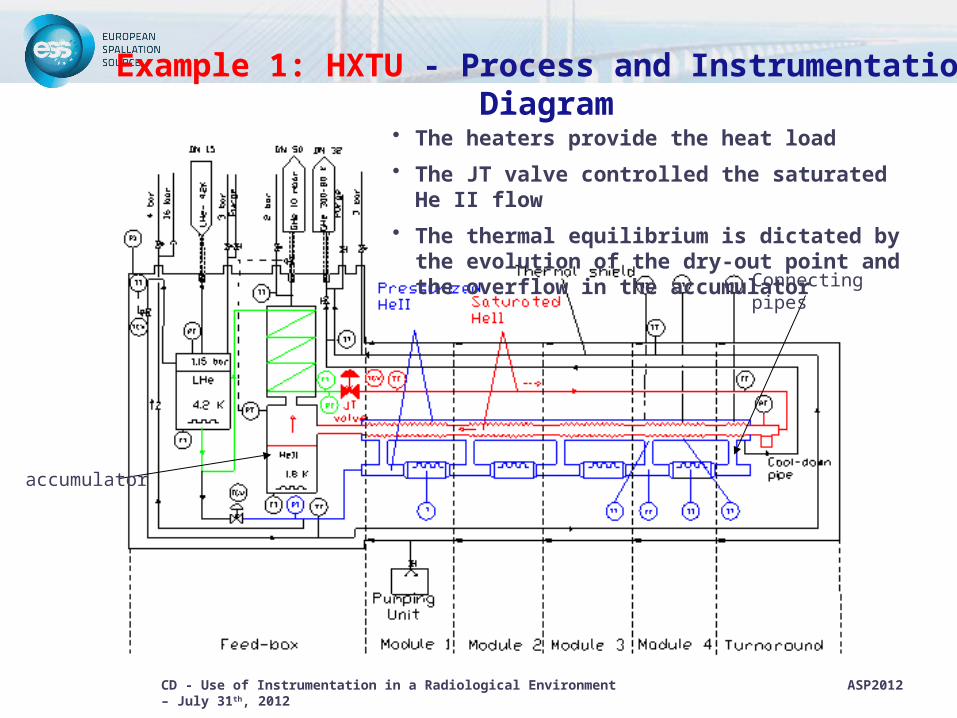
Example 1: HXTU - Process and Instrumentation Diagram
accumulator
Connecting pipes
• The heaters provide the heat load
• The JT valve controlled the saturated He II flow
• The thermal equilibrium is dictated by the evolution of the dry-out point and the overflow in the accumulator
CD - Use of Instrumentation in a Radiological Environment ASP2012 – July 31th, 2012
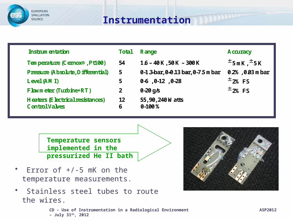
Instrumentation
Temperature sensors implemented in the pressurized He II bath
Instrumentation Total Range Accuracy
Temperature (Cernox®, Pt100) 54 1.6 – 40 K, 50 K – 300 K 5 mK, 5 K
Pressure (Absolute, Differential) 5 0-1.3 bar, 0-0.13 bar, 0-7.5 mbar 0.2%, 0.03 mbar
Level (AMI) 5 0-6”, 0-12”, 0-28” 2% FS
Flowmeter (Turbine+RT) 2 0-20 g/s 2% FS
Heaters (Electrical resistances) 12 55, 90, 240 WattsControl Valves 6 0-100 %
• Error of +/-5 mK on the temperature measurements.
• Stainless steel tubes to route the wires.
CD - Use of Instrumentation in a Radiological Environment ASP2012 – July 31th, 2012 19
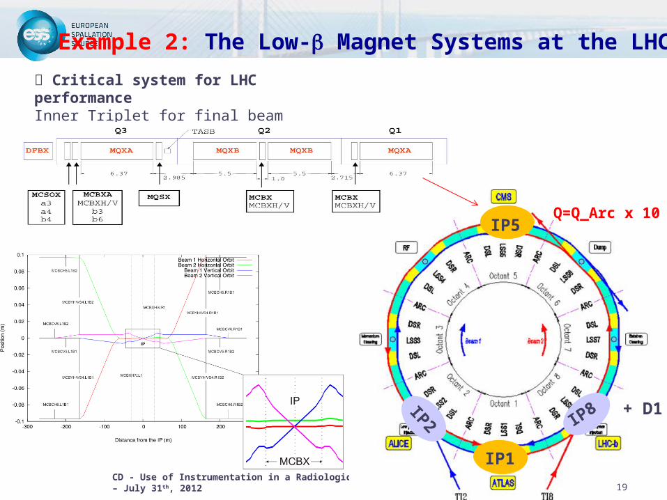
Example 2: The Low-b Magnet Systems at the LHC
19
Critical system for LHC performanceInner Triplet for final beam focusing/defocusingAmerican contribution to the LHC machine
IP2 IP8 + D1
IP5
IP1
Q=Q_Arc x 10
CD - Use of Instrumentation in a Radiological Environment ASP2012 – July 31th, 2012 20
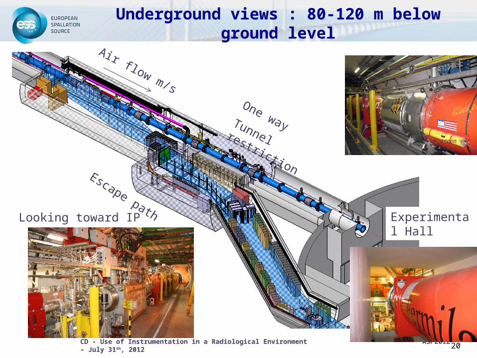
Underground views : 80-120 m below ground level
Air flow m/s
Escape path
One wayTunnel restriction
Experimental Hall
Looking toward IP
CD - Use of Instrumentation in a Radiological Environment ASP2012 – July 31th, 2012 21
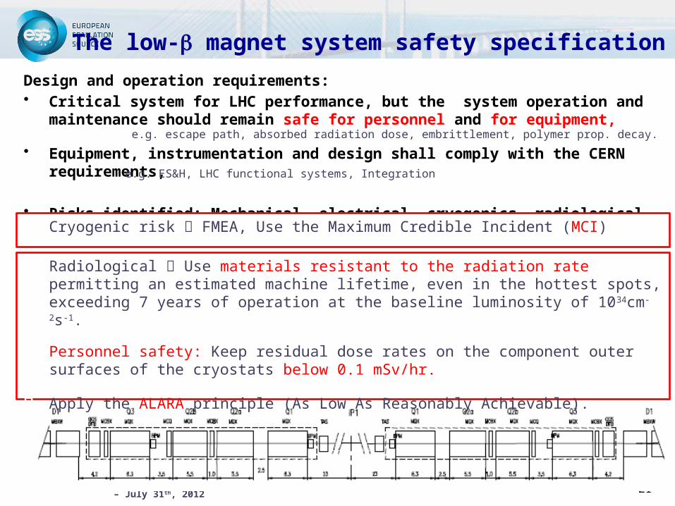
The low-b magnet system safety specification
Design and operation requirements: • Critical system for LHC performance, but the system operation and
maintenance should remain safe for personnel and for equipment,
• Equipment, instrumentation and design shall comply with the CERN requirements,
• Risks identified: Mechanical, electrical, cryogenics, radiological
e.g. escape path, absorbed radiation dose, embrittlement, polymer prop. decay.
e.g. ES&H, LHC functional systems, Integration
Cryogenic risk FMEA, Use the Maximum Credible Incident (MCI)
Radiological Use materials resistant to the radiation rate permitting an estimated machine lifetime, even in the hottest spots, exceeding 7 years of operation at the baseline luminosity of 1034cm-2s-1.
Personnel safety: Keep residual dose rates on the component outer surfaces of the cryostats below 0.1 mSv/hr.
Apply the ALARA principle (As Low As Reasonably Achievable).
CD - Use of Instrumentation in a Radiological Environment ASP2012 – July 31th, 2012 22
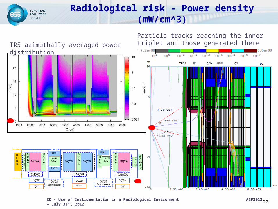
Radiological risk - Power density (mW/cm^3)
Particle tracks reaching the inner triplet and those generated there for a pp-collision in the IP1IR5 azimuthally averaged power distribution.
CD - Use of Instrumentation in a Radiological Environment ASP2012 – July 31th, 2012 23
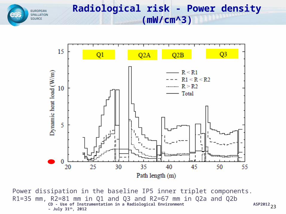
Radiological risk - Power density (mW/cm^3)
Power dissipation in the baseline IP5 inner triplet components. R1=35 mm, R2=81 mm in Q1 and Q3 and R2=67 mm in Q2a and Q2b
CD - Use of Instrumentation in a Radiological Environment ASP2012 – July 31th, 2012 24
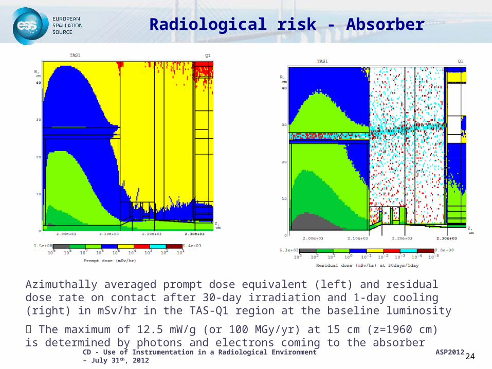
Radiological risk - Absorber
Azimuthally averaged prompt dose equivalent (left) and residual dose rate on contact after 30-day irradiation and 1-day cooling (right) in mSv/hr in the TAS-Q1 region at the baseline luminosity
The maximum of 12.5 mW/g (or 100 MGy/yr) at 15 cm (z=1960 cm) is determined by photons and electrons coming to the absorber
CD - Use of Instrumentation in a Radiological Environment ASP2012 – July 31th, 2012 25
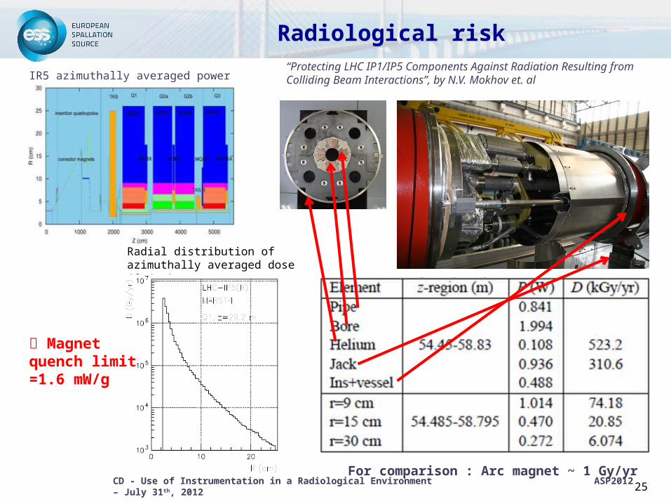
Radial distribution of azimuthally averaged dose (Gy/yr)
Radiological risk
IR5 azimuthally averaged power distribution
For comparison : Arc magnet ~ 1 Gy/yr
Magnet quench limit =1.6 mW/g
“Protecting LHC IP1/IP5 Components Against Radiation Resulting from Colliding Beam Interactions”, by N.V. Mokhov et. al
CD - Use of Instrumentation in a Radiological Environment ASP2012 – July 31th, 2012 26
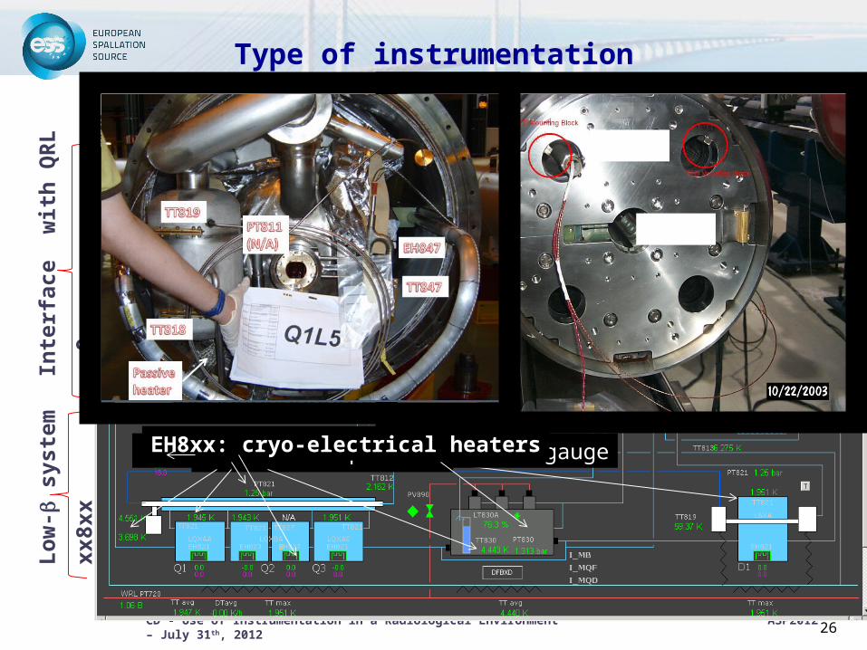
Type of instrumentationIn
terf
ace
wit
h Q
RL
xx9x
x
Lo
w-b
sys
tem
xx8x
x
TT8xx: Pt100, CernoxTMPT8xx: based on passive strain gaugeEH8xx: cryo-electrical heaters
TT821
EH821

CD - Use of Instrumentation in a Radiological Environment ASP2012 – July 31th, 2012 27
CV8xx: control valveType of instrumentation
LT8xx: liquid helium level gauge
(based on superconducting wire)
*HTS leads
*VCL leads
*Inner triplet feed through
CD - Use of Instrumentation in a Radiological Environment ASP2012 – July 31th, 2012 28
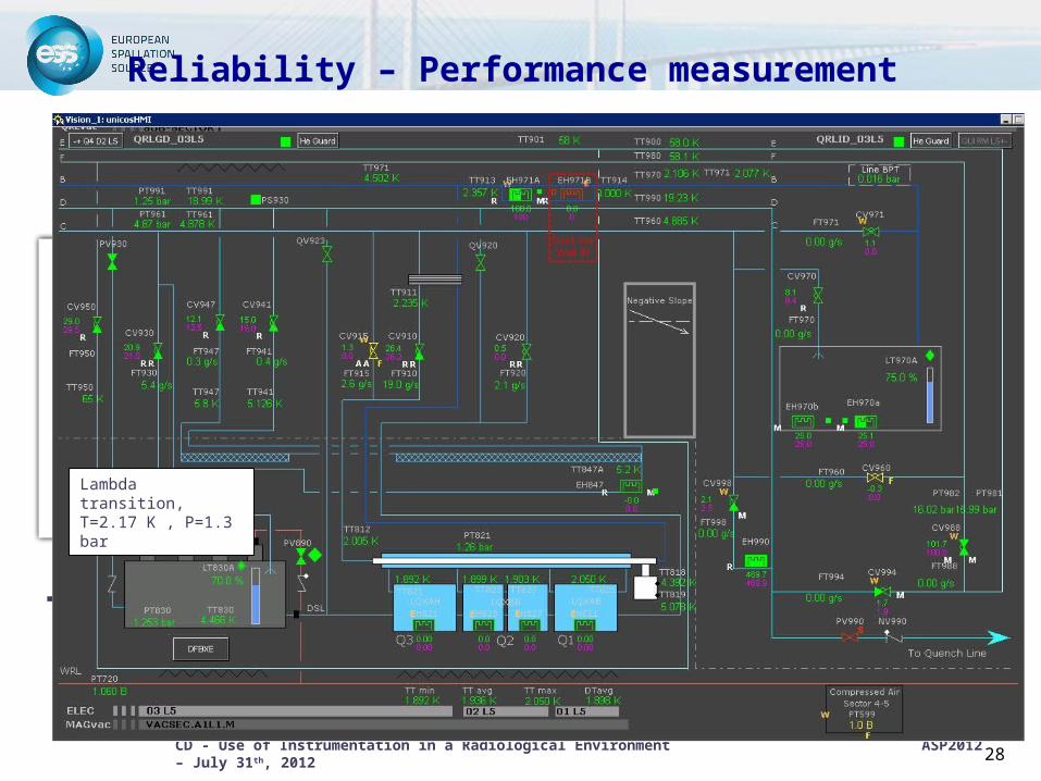
Reliability – Performance measurement
Temperature homogeneity to qualify the measurement chain and to evaluate the dispersion between the different sensors.
Lambda transition, T=2.17 K , P=1.3 bar
CD - Use of Instrumentation in a Radiological Environment ASP2012 – July 31th, 2012 29
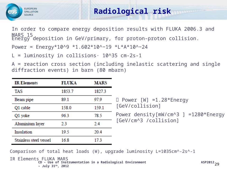
Radiological risk
Comparison of total heat loads (W), upgrade luminosity L=1035cm^-2s^-1
IR Elements FLUKA MARS
In order to compare energy deposition results with FLUKA 2006.3 and MARS 15
Energy deposition in GeV/primary, for proton-proton collision.
Power = Energy*10^9 *1.602*10^−19 *L*A*10^−24
L = luminosity in collisions· 10^35 cm-2s-1
A = reaction cross section (including inelastic scattering and single diffraction events) in barn (80 mbarn)
Power [W] =1.28*Energy [GeV/collision]
Power density[mW/cm^3 ] =1280*Energy [GeV/cm^3 /collision]
CD - Use of Instrumentation in a Radiological Environment ASP2012 – July 31th, 2012 30
Radiological risk mitigation
• The inner-triplet final design included additional radiation shielding and copper absorber (TAS)
• The chosen instrumentation and equipment are radHard and halogen free (neutron irradiation experiment performed on temperature sensors : fluence values close to 1015 neutrons/cm2, corresponding to 2.104 Gy).
• PEEK versus Kel-F material used for the DFBX low temperature gas seal
• LHC tunnel accesses modes were defined, e.g. control and restricted modes

CD - Use of Instrumentation in a Radiological Environment ASP2012 – July 31th, 2012 31
Radiological risk mitigation
Averaged over surface residual dose rate (mSv/hr) on the Q1 side (z=2125 cm, bottom) of the TAS vs irradiation and cooling times. By courtesy of N. Mokhov
• Specific hazard analysis is requested to intervene on the low-b systems
• Radiological survey systematical performed (< 1mSv/hr)
• Procedures written based on lessons learned
• Limit the personnel exposition time
• Process control w/ interlocks and alarm level for each operating mode
CD - Use of Instrumentation in a Radiological Environment ASP2012 – July 31th, 2012 32
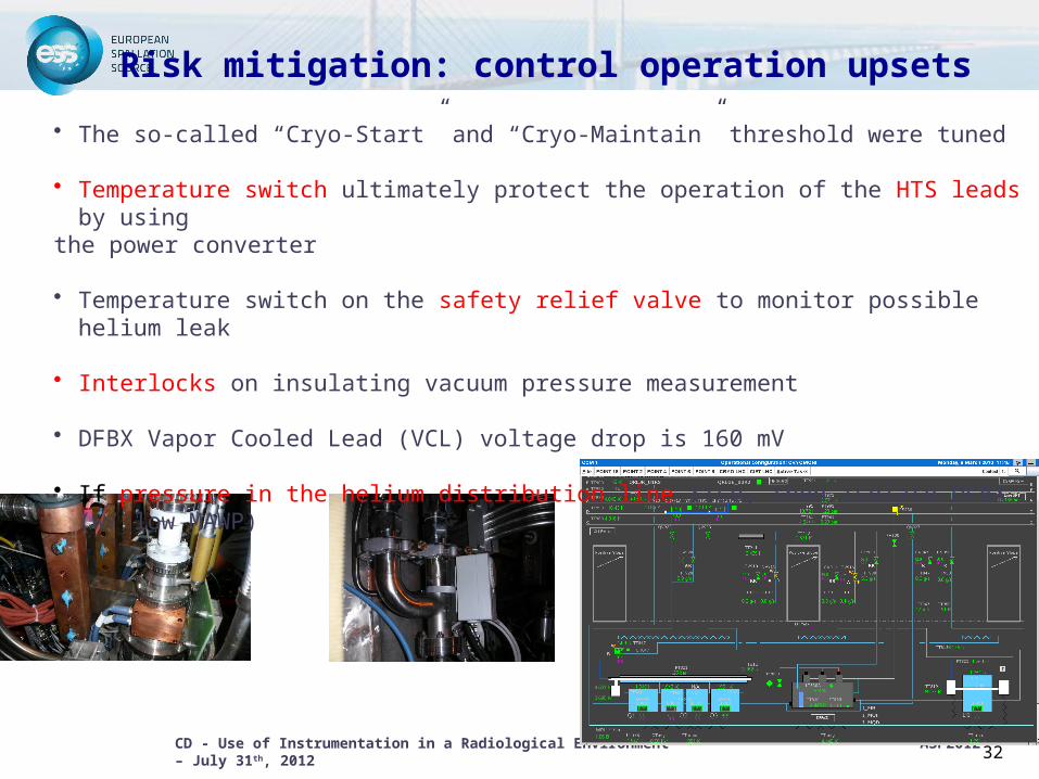
Risk mitigation: control operation upsets
• The so-called “Cryo-Start” and “Cryo-Maintain” threshold were tuned
• Temperature switch ultimately protect the operation of the HTS leads by using the power converter
• Temperature switch on the safety relief valve to monitor possible helium leak
• Interlocks on insulating vacuum pressure measurement
• DFBX Vapor Cooled Lead (VCL) voltage drop is 160 mV
• If pressure in the helium distribution line rise, then isolate DFBX (w/ low MAWP)
CD - Use of Instrumentation in a Radiological Environment ASP2012 – July 31th, 2012 33
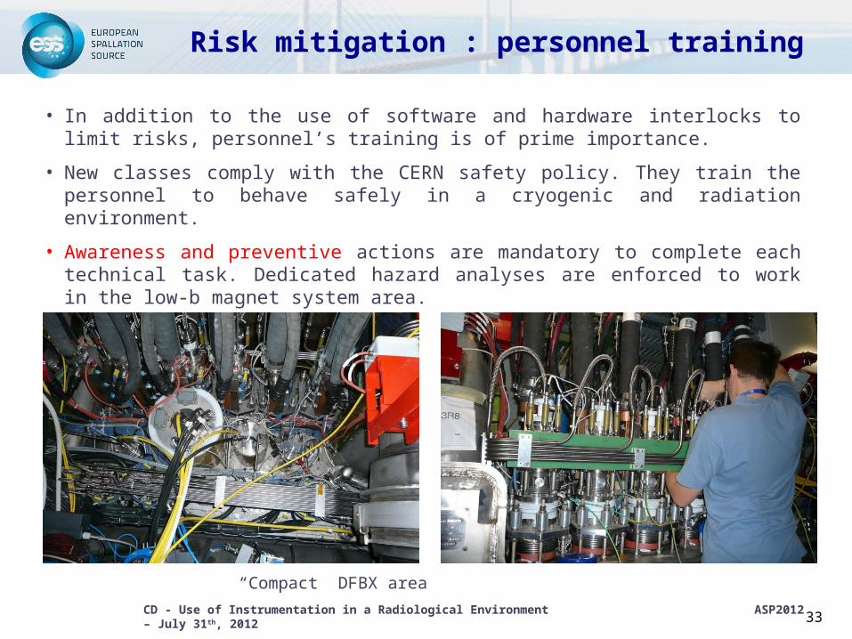
Risk mitigation : personnel training
• In addition to the use of software and hardware interlocks to limit risks, personnel’s training is of prime importance.
• New classes comply with the CERN safety policy. They train the personnel to behave safely in a cryogenic and radiation environment.
• Awareness and preventive actions are mandatory to complete each technical task. Dedicated hazard analyses are enforced to work in the low-b magnet system area.
“Compact” DFBX area
CD - Use of Instrumentation in a Radiological Environment ASP2012 – July 31th, 2012 34
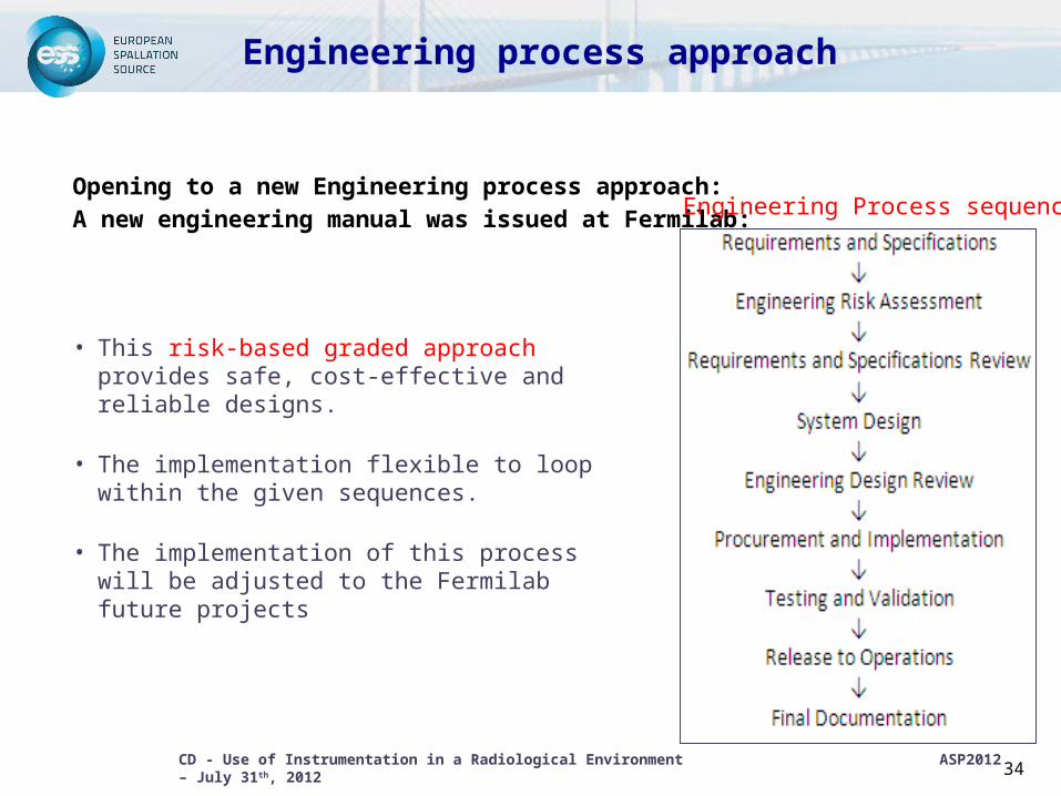
Engineering process approach
Opening to a new Engineering process approach:A new engineering manual was issued at Fermilab:
• This risk-based graded approach provides safe, cost-effective and reliable designs.
• The implementation flexible to loop within the given sequences.
• The implementation of this process will be adjusted to the Fermilab future projects
Engineering Process sequences
CD - Use of Instrumentation in a Radiological Environment ASP2012 – July 31th, 2012
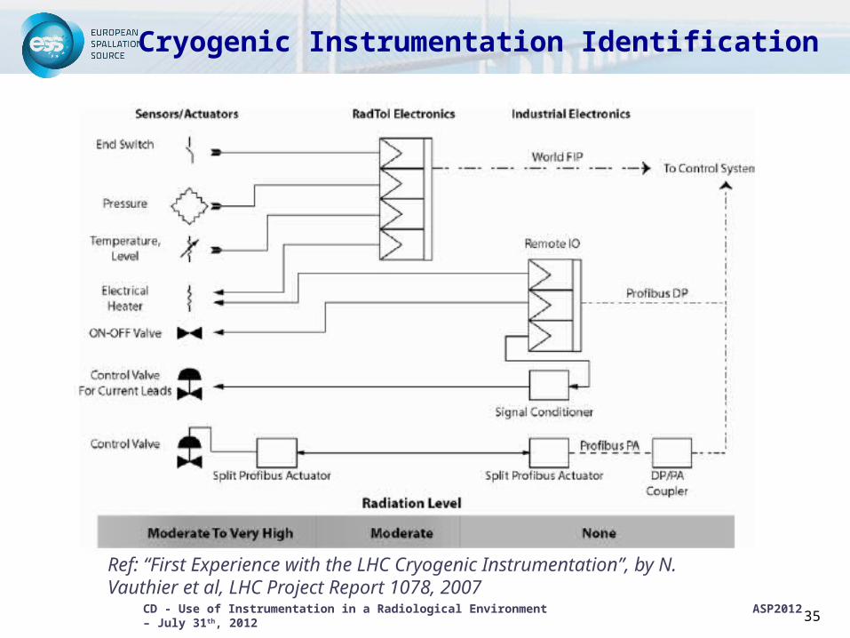
Cryogenic Instrumentation Identification
35
Ref: “First Experience with the LHC Cryogenic Instrumentation”, by N. Vauthier et al, LHC Project Report 1078, 2007
CD - Use of Instrumentation in a Radiological Environment ASP2012 – July 31th, 2012
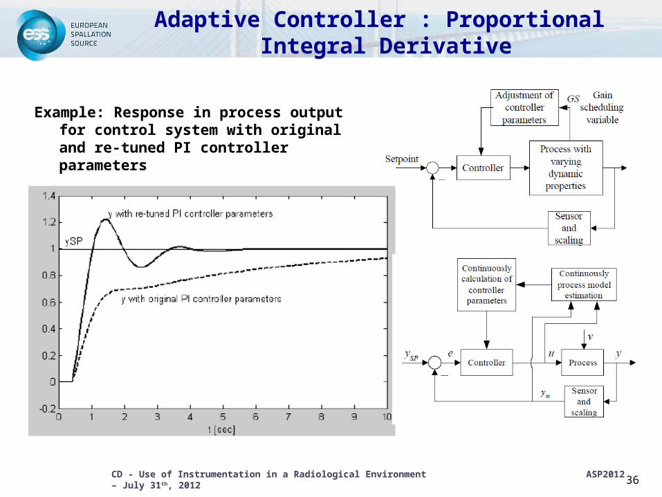
Adaptive Controller : Proportional Integral Derivative
Example: Response in process output for control system with original and re-tuned PI controller parameters
36
CD - Use of Instrumentation in a Radiological Environment ASP2012 – July 31th, 2012
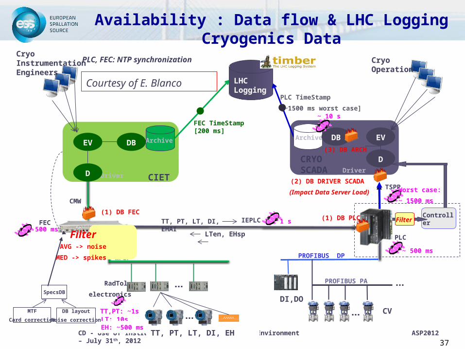
Availability : Data flow & LHC Logging Cryogenics Data
37
Controller
CRYO SCADA
PROFIBUS PA
WFIP
RadTol
electronics
PLC
TT, PT, LT, DI, EH
CV
DI,DO
PROFIBUS DP
LHC Logging
FEC500 ms
Worst case:
~ 1500 ms
1 sTT, PT, LT, DI, EHAI
LTen, EHsp
CIETDriverDriver
ArchiveArchive
PLC TimeStamp
[~1500 ms worst case]
FEC TimeStamp[200 ms]
(1) DB FEC(1) DB PLC
(2) DB DRIVER SCADA
(Impact Data Server Load)
(3) DB ARCHEV
D
DB
D
EVDB
Cryo Instrumentation Engineers
Cryo Operation
CMW
IEPLC
TT,PT: ~1sLT: 10s
EH: ~500 ms
~ 500 ms
~ 10 s
Courtesy of E. Blanco
PLC, FEC: NTP synchronization
FilterAVG -> noise
MED -> spikes
SpecsDB
MTF
Card correction
DB layout
Noise correction
TSPP
Filter
CD - Use of Instrumentation in a Radiological Environment ASP2012 – July 31th, 2012 38
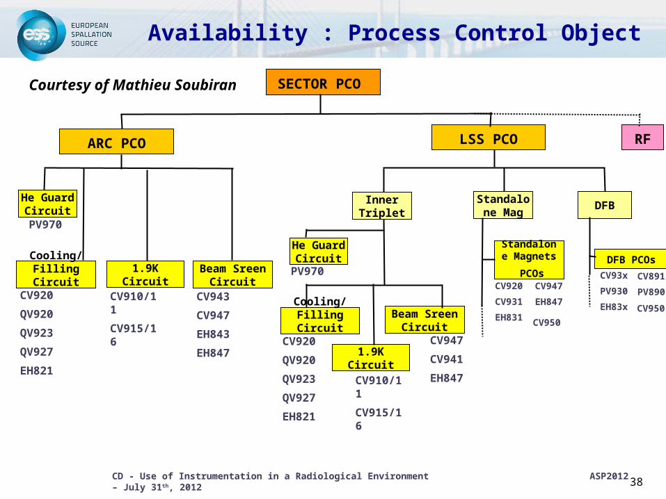
Availability : Process Control Object
Courtesy of Mathieu Soubiran
SECTOR PCO
ARC PCO LSS PCO
He Guard Circuit
Cooling/Filling Circuit
1.9K Circuit Beam Sreen Circuit
Standalone Mag
DFB
He Guard Circuit
Cooling/Filling Circuit
1.9K Circuit
Beam Sreen Circuit
PV970
PV970
CV920
QV920
QV923
QV927
EH821
CV910/11
CV915/16
CV943
CV947
EH843
EH847CV920
QV920
QV923
QV927
EH821
CV910/11
CV915/16
CV947
CV941
EH847
Inner Triplet
RF
DFB PCOs
CV93x
PV930
EH83x
CV891
PV890
CV950
Standalone
Magnets
PCOs
CV950
CV920
CV931
EH831
CV947
EH847
CD - Use of Instrumentation in a Radiological Environment ASP2012 – July 31th, 2012 39
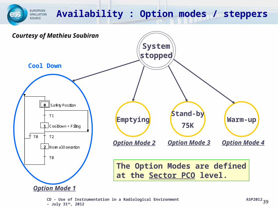
Availability : Option modes / steppers
Courtesy of Mathieu Soubiran
Stand-by
75K
Systemstopped
Emptying Warm-up
0 Safety Position
T1
1 Cooldown + Filling
T0 T2
2 Normal Operation
T0
Cool Down
Option Mode 1
Option Mode 2 Option Mode 3 Option Mode 4
The Option Modes are defined at the Sector PCO level.
CD - Use of Instrumentation in a Radiological Environment ASP2012 – July 31th, 2012
40
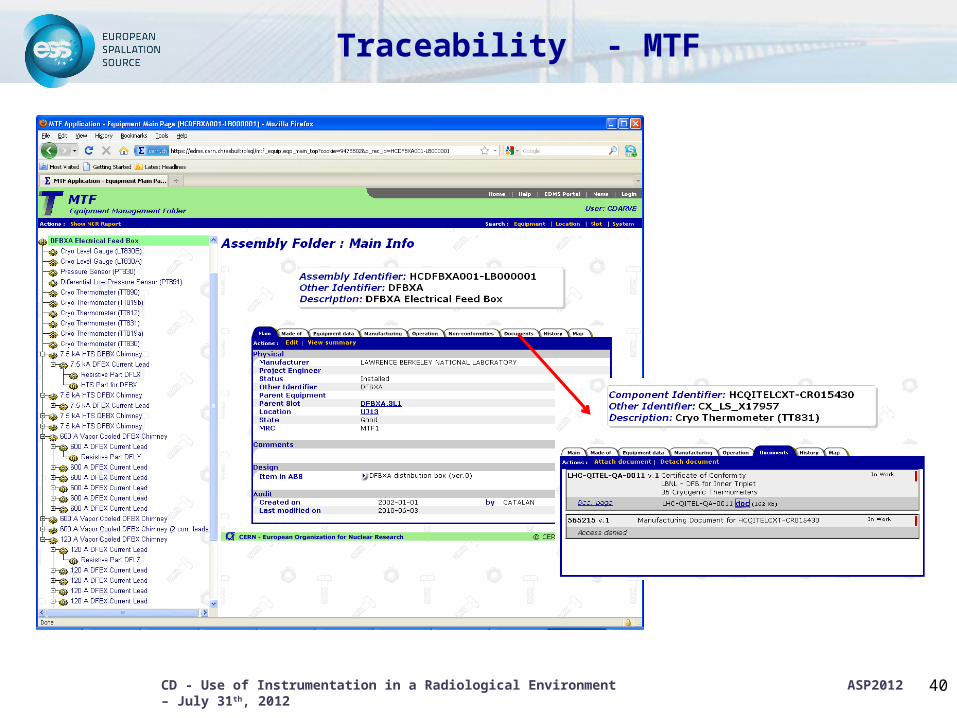
Traceability - MTF