Embed Size (px)
Citation preview

CP2-RP-1009/FR1
Radiological Protection Instrumentation Operation
Technical Basis Document
Total Page Count: 183
WORKING COPY
VERIF. DATE:
INTIALS:

Total Pages: 183
CP2-RP-1009/FR1
Radiological Protection Instrumentation
Operation Technical Basis Document
Date Issued—December 2017

CP2-RP-1009/FR1
THIS PAGE INTENTIONALLY LEFT BLANK

CP2-RP-1009/FR1
APPROVALS
Radiological Protection Instrumentation
Operation Technical Basis Document
CP2-RP-1009/FR1
Issued—December 2017
Approved: _Signature on file_____________________________ Date: __12/13/17_________________
Roland Chretien
HSS&Q Director

CP2-RP-1009/FR1
THIS PAGE INTENTIONALLY LEFT BLANK
CP2-RP-1009/FR1
iii
CONTENTS
TABLES ....................................................................................................................................................... v ACRONYMS .............................................................................................................................................. vii 1. INTRODUCTION .................................................................................................................................... 1 2. INSTRUMENTATION ............................................................................................................................ 1
2.1 LOW DOSE RANGE BETA-GAMMA INSTRUMENTS ............................................................ 1
2.5.1 Bicron Microrem Meter (Regular and Low-Energy Models) .......................................... 2 2.2 MEDIUM DOSE RANGE BETA-GAMMA SURVEY INSTRUMENTS ................................... 4
2.2.1 Bicron RSO-5 Survey Meter ............................................................................................ 6 2.2.2 Bicron RSO-50E Survey Meter........................................................................................ 8 2.2.3 Eberline RO-2 Survey Meter ......................................................................................... 10 2.2.4 Eberline RO-20 Survey Meter........................................................................................ 11
2.3 HIGH DOSE RANGE BETA-GAMMA INSTRUMENTS ......................................................... 13
2.3.1 Eberline 6112B Survey Meter ........................................................................................ 14 2.3.2 Automess 6150 AD2 Survey Meter ............................................................................... 15
2.4 NEUTRON SURVEY INSTRUMENTS ..................................................................................... 18
2.4.1 Eberline E-600 Ratemeter/Scaler ................................................................................... 19 2.4.2 Eberline ASP-2/2E ......................................................................................................... 22
2.5 DOSIMETERS ............................................................................................................................. 24
2.5.1 Canary III Electronic Pocket Dosimeter ........................................................................ 24 2.5.2 MGP Instruments DMC 2000 S Electronic Dosimeter .................................................. 26 2.5.3 Siemens EPD Mk2 Personal Electronic Dosimeter ....................................................... 28
2.6 PORTABLE CONTAMINATION MONITORING INSTRUMENTS ....................................... 32
2.6.1 Ludlum Model 3 Count Ratemeter................................................................................. 32 2.6.2 Ludlum Model 12 Count Ratemeter............................................................................... 35 2.6.3 Ludlum Model 177 Count Ratemeter............................................................................. 37 2.6.4 Ludlum Model 177-45 Count Ratemeter ....................................................................... 40 2.6.5 Ludlum Model 2221 Count Ratemeter/Scaler ............................................................... 43 2.6.6 Ludlum Model 2224 Count Ratemeter/Scaler ............................................................... 48 2.6.7 Ludlum Model 2360/2224-1 Count Ratemeter/Scaler ................................................... 51 2.6.8 Bicron Frisk Tech Count Ratemeter............................................................................... 55 2.6.9 Bicron Surveyor M-X .................................................................................................... 58
2.7 DETECTORS ............................................................................................................................... 60
2.7.1 Bicron PGM Detector .................................................................................................... 61 2.7.2 Bicron TPGM Detector .................................................................................................. 63 2.7.3 Ludlum Model 44-2 and Eberline SPA-8 NaI Gamma Scintillators .............................. 65 2.7.4 Ludlum Model 43-5 Alpha Scintillator .......................................................................... 66 2.7.5 Ludlum Model 43-10-1 .................................................................................................. 68 2.7.6 Ludlum Model 43-37/43-37-1 Detectors and Model 239-1 Floor Monitor ................... 70 2.7.7 Ludlum Model 43-65 Alpha Scintillator ........................................................................ 73 2.7.8 Ludlum Model 43-68 Gas Proportional Detector .......................................................... 74 2.7.9 Ludlum Model 43-89 and 43-93 Alpha/Beta Scintillators ............................................. 77 2.7.10 Ludlum Model 44-9 Geiger-Müeller Detector ............................................................. 79 2.7.11 Ludlum Models 44-3, 44-10, and 44-17 Gamma Scintillators ..................................... 81 2.7.12 Ludlum Model 44-40 Geiger-Müeller Detector ........................................................... 83 2.7.13 NE Technology DP6-CD Alpha/Beta Scintillator ....................................................... 84 2.7.14 NE Technology DP-6BD Alpha/Beta Scintillator ....................................................... 86

CP2-RP-1009/FR1
iv
2.7.15 Bicron Model G5 Scintillation Detector ...................................................................... 88 2.8 PERSONAL AIR SAMPLERS .................................................................................................... 89
2.8.1 Buck Basic 12 Personal Air Sampling Pump ................................................................. 90 2.8.2 Buck VSS-12 Personal Air Sampling Pump .................................................................. 92 2.8.3 Buck Libra Plus Model LP-12 Personal Air Sampling Pump ........................................ 95 2.8.4 Buck Libra Plus Model LP-7 Personal Air Sampling Pump .......................................... 98
2.9 LOW-VOLUME AIR SAMPLERS ........................................................................................... 101
2.9.1 Hi-Q MRV-1023 CV and MRV-0523C Low Volume Area Air Samplers .................. 101 2.9.2 SAIC AVS-28A and HD-29A Low Volume Area Air Samplers ................................. 103 2.9.3 PQ-100 Solar-Powered Air Sampler ............................................................................ 105 2.9.4 Allegro T-100 Sampling Pump (Rotary Vane)/T-100M Sampling Pump (Rotary
Vane) with Flow Meter ......................................................................................... 109 2.10 HIGH VOLUME AIR SAMPLERS ......................................................................................... 110
2.10.1 HVP-3800 AFC .......................................................................................................... 111 2.10.2 TFIA High Volume Air Sampler ............................................................................... 113 2.10.3 SAIC H-809C High Volume Air Sampler ................................................................. 115
2.11 CONTINUOUS AIR MONITORS ........................................................................................... 117
2.11.1 Eberline Alpha-6A and 6A-1 Particulate Air Monitors ............................................. 118 2.12 SAMPLER CALIBRATORS AND AUXILIARY EQUIPMENT........................................... 124
2.12.1 Bios Dry Cal DC-1 Flow Calibrator .......................................................................... 124 2.12.2 Bios Defender 510 and Defender 520 Flow Calibrator .............................................. 126 2.12.3 F&J Digital Venturi Airflow Calibrator ..................................................................... 128 2.12.4 Hi-Q HFC-50C Calibrator .......................................................................................... 130 2.12.5 Mini-Buck Primary Flow Calibrator .......................................................................... 131 2.12.6 SAIC Air Flow Calibrators ........................................................................................ 132
2.13 LABORATORY INSTRUMENTATION ................................................................................ 133
2.13.1 Ludlum Model 2929 Alpha/Beta Scaler ..................................................................... 134 2.13.2 Ludlum Model 3030 Alpha/Beta Scaler ..................................................................... 137
2.14 NONPORTABLE AND SPECIALTY INSTRUMENTS ........................................................ 140
2.14.1 Aptec AHF-2000 Hand and Foot Monitor ................................................................. 141 2.14.2 Canberra Sirius-4AB Hand and Foot Monitor ........................................................... 143 2.14.3 Bicron Model LFM-2 Radioactive Material Detection System ................................. 146 2.14.4 Global Positioning System Gamma Ray Survey Instrumentation ............................. 149 2.14.5 Canberra InSpector Gamma Spectrometer ................................................................. 152 2.14.6 Genitron Gamma Tracer Area Monitor ...................................................................... 154 2.14.7 Canberra Argos-4A.B Whole Body Monitor ............................................................. 155 2.14.8 Canberra iSolo
® Alpha/Beta Counting System .......................................................... 158
2.14.9 Canberra Argos-5AB Whole Body Monitor .............................................................. 162 2.14.10 Berthold LB 1043 AS Hand and Foot Monitor ........................................................ 164 2.14.11 Eberline PCM-2 Personnel Contamination Monitor ................................................ 167 2.14.12 Ludlum Model 329-32 Laundry Monitor ................................................................. 170

CP2-RP-1009/FR1
v
TABLES
Table 1. Buck VSS-12 Operating Menus and Submenus ........................................................................... 93 Table 2. Error Messages that Might Be Displayed ................................................................................... 107 Table 3. Configuration Menu .................................................................................................................... 151 Table 4. Sensors ........................................................................................................................................ 156

CP2-RP-1009/FR1
THIS PAGE INTENTIONALLY LEFT BLANK

CP2-RP-1009/FR1
vii
ACRONYMS
ALARA as low as reasonable achievable
APGM aluminum portable Geiger-Müeller
BCF beta correction factor
CAM continuous air monitor
CFM cubic feet per minute
cpm counts per minute
DAC derived air concentration
D&R Deactivation and Remediation Contractor
G-M Geiger-Müeller
GPS Global Positioning System
IR infrared
kV kilovolts
LCD liquid crystal display
LED light emitting diode
lpm liter per minute
LPGM lead portable Geiger-Müeller
MCA multichannel analyzer
meV millielectron volt
mm millimeter
mR/h milliroentgen/hour
mrem millirem
mrem/h millirem/hour
NaI sodium iodide
NRD neutron rem detector
PDOP position dilution of precision
PGDP Paducah Gaseous Diffusion Plant
PHA pulse height analysis
psig pounds per square inch gravity
R/h roentgens/h
RADCON radiological control
RCT radiological control technician
ROI region of interest
RPM radiation protection manager
RWP radiation work permit
SCA single channel analyzer
SCFM standard cubic feet per minute
TEPC tissue equivalent proportional counter
Tl thallium
TPGM tungsten portable Geiger-Müeller
μrem microrem

CP2-RP-1009/FR1
THIS PAGE INTENTIONALLY LEFT BLANK

CP2-RP-1009/FR1
1
1. INTRODUCTION
The purpose of this document is to provide guidance on techniques and practices that are used by
qualified radiological control (RADCON) personnel at Paducah Gaseous Diffusion Plant (PGDP) D&R
for operation of various radiological instruments.
The use of this document requires the use of the Deactivation and Remediation Contractor (D&R)D&R
RADCON procedures as this document is intended to augment and not duplicate or replace specific
requirements specified in the procedures. No additional RADCON requirements are established by this
guide and mandatory performance of any practice indicated is strictly limited to those required by
approved D&RD&R RADCON procedures.
2. INSTRUMENTATION
2.1 LOW DOSE RANGE BETA-GAMMA INSTRUMENTS
In this context, low dose rates are on the order of μR/h and μrem/h. These measurements typically are
taken to determine the ambient natural background and to otherwise measure levels up to ~ 500 μR/h (or
μrem/h). Higher levels (to ~ 5 mR/h) should be measured with a gamma compensated Geiger-Müeller
(G-M) detector. An ion chamber instrument should be used to measure exposure rates above 5 mR/h.
When appropriate, telescoping or “fish pole” extended detectors are used to reduce personnel exposure
while taking elevated measurements. The current inventory of low dose range instruments cannot provide
direct measurements to determine beta radiation levels; only gamma ray levels can be measured.
Two types of detectors are available. One is NaI (Tl) gamma scintillation and the other is organic
scintillation. Sensitivity is equivalent. The organic gamma scintillation detector has the advantage of near
tissue-equivalence and of relatively uniform gamma energy response. Gamma ray energy response curves
are provided for specific instruments in this section.
All instruments used for low dose
range measurements use scintillation
detectors coupled to photomultiplier
tubes to amplify the pulse. The
photomultiplier tubes are vulnerable to
electronic interference such as radio
frequency signals. The apparent levels
can be elevated by a keyed radio
nearby.
The analog meters are difficult to read at ambient background (e.g., 5–10 μR/h) because the meter swings
are on the order of ± 20% or more. Judgment is required to estimate the center of those swings and
precision is limited to that 20%. As exposure rates increase the precision is relatively improved.
The accuracy of NaI (Tl) exposure rate measurements in the field is limited, but typically conservative.
Over-response is expected as noted in the energy response curves. Over-response is greatest in the energy
range of 100 keV. The detectors are housed within their respective instrument cases and that “shielding”
effectively prevents measurement of photons below 40 keV. Laboratory calibrations to a specific gamma

CP2-RP-1009/FR1
2
ray energy (or energies), or to specific gamma ray emitting radionuclides, cannot mimic field conditions.
Variable and nonspecific scatter of the primary gamma ray energies in the field denies accuracy although
over-response is expected. Over-response in the measured exposure rate by a factor of two is not unusual.
Gamma emitting contaminants rarely are distributed uniformly over an area or depth in the field. If
uniform distribution does occur, then exposure rate measurements can be improved by correlation to like
measurements with a pressurized ion chamber or with an organic scintillation detector.
Instruments frequently are calibrated to exposure rate (e.g., mR/h). Conversion to dose rate (mrem/h)
depends on the range and distribution of gamma ray energies, but the dose rate is always lower than the
exposure rate.
An important field application, for both types of detectors, is to establish background or baseline exposure
rates. The number and distribution of background measurements that will be required is based upon the
data quality objectives. The quality and statistical confidence of the background measurements depends
upon the uniformity of those measurements. A greater number of measurements likely will be required
when the levels are variable (e.g., greater than a factor of two or three difference among the
measurements). A statistical analysis of the survey data will establish the level of confidence for
comparison to the survey objectives. These same considerations also apply to slightly elevated
measurements that may be required by the data quality objectives. For example, a typical survey plan
might require an action level of twice the ambient background.
Gamma “shine” from remote “hot spots” or other gamma emitting sources may affect field
measurements.
One way of identifying a remote source is to note the difference between measurements at the surface
compared to measurements elevated above the surface. If measurements at the surface are lower, then a
remote source is indicated. Precise distinction is unlikely. Comparison to other measurements in that
same area, which may be less affected, can assist in the analysis.
Use of shielded collimators can reduce the remote contribution when lower energized gamma or photon
emitters are involved. However, if the gamma energies are relatively higher, use of a shield collimator
becomes impractical because of the weight of the detector.
Larger NaI (Tl) detectors (2 inch x 2 inch), with scaler/ratemeters, are used for sensitive gamma ray
surveys in the field, but the recorded count rates are difficult to correlate with exposure rates. The
scaler/ratemeters are used primarily for surface contamination measurements and are covered in that
section of this guide.
2.1.1 Bicron Microrem Meter (Regular and Low-Energy Models)
The Bicron Micro Rem Meter is a portable survey meter for equivalent dose
rate measurements of low photon radiation levels. A tissue-equivalent
organic scintillation detector provides a flat energy response in equivalent
dose rate (μR/h) for X-ray and gamma photons in the energy range of
approximately 40 keV–1.3 MeV. This instrument is also available in a
“Low-Energy Response” option, which extends the tissue-equivalent
response range down to approximately 17 keV.
The Bicron Micro Rem Meter survey instrument has an effective
measurement range of 0–200 mrem/h. Ranges are x 0.1 0–20 μrem/h, x 1 (0–
200 μrem/h), x 10 (0–2 mrem/h), x 100 (0–20 mrem/h), and x 100 (0–200 mrem/h). On-Off, battery test,

CP2-RP-1009/FR1
3
high voltage check, and five range selections are controlled by the same switch. There is also a reset
button on the same panel as the switch control knob. Some models of this instrument are equipped to
provide an audible signal with a frequency proportional to the radiation level. An alarm setting is also
available on some models.
Applications—The Bicron Micro Rem Meter is used to measure direct radiation levels in units of
equivalent dose rate (i.e., μrem/h). Because of the tissue equivalent response to photon radiation,
readings from this instrument accurately indicate the equivalent dose for the range of photon energies
typically encountered in operations, and measurements can be compared directly with control levels
and regulatory limits. The Bicron Micro Rem Meter can be used to measure accurately area radiation
levels ranging from typical background values to those expected in all operations, except where
significant quantities of fission and/or activation products are present.
Controls and Display
— bat.—Power is provided by two 9-volt batteries. Only one battery is required to operate the
instrument; however, battery life is extended with both batteries installed. The rotary switch is
placed in the bat., position to test the battery level; a response of the meter needle in the bat. ok
range indicates that there is sufficient power to operate the instrument.
— HV—When the switch is placed in the HV position, the needle response in the HV ok range
indicates that the instrument voltage is acceptable for operation.
— SCALES—The five ranges are described in general description above.
— RESET—Depressing and releasing this optional push button switch quickly resets the meter to
zero.
— DISPLAY—All measurements and indication of battery and high voltage tests are indicated on
the single analog meter display.
Additional Features and Auxiliary Equipment—There are no items of auxiliary equipment
required to use this instrument. Optional features on some models may include an audible signal
output and an alarm preset.
Limitations and Precautions—The low-energy model has a fragile detector covering that must be
protected from damage. The range of this instrument limits its applications to measuring radiation
levels below 200 mrem/h.
Operation
— Confirm that the instrument has a current and legible calibration label; if not, remove from
service and do not use until the condition is corrected.
— Determine the lower-photon energy range of interest; if less than 40 keV, select the low-energy
response model. Historical, job process, and other work documents should provide information
regarding radionuclides and types of contamination expected. This information is available from
the radiological control technician (RCT) supervisor and typically is provided on the radiation
work permit (RWP) for the survey(s) to be performed. This information will assist in the proper
selection of instrumentation.

CP2-RP-1009/FR1
4
— Ensure that the daily instrument performance tests have been satisfactorily completed (all
readings are within the defined acceptable range) and documented on a daily test sheet or perform
those tests in accordance with established procedure.
— Turn the instrument switch to bat. Ensure that the needle response is in the indicated range of
bat. ok; if not, remove from service and do not use until condition is corrected.
— Turn the instrument switch to HV. Ensure that the needle response is near the center of the
indicated range of HV ok; if not, remove from service and do not use until condition is corrected.
— Holding the instrument away from the body and in the radiation field of interest, turn the scale
switch to highest scale allowing several seconds (approximately 15–20 seconds depending on
scale), for response. Continue to select lower scales until the meter indication is as high as
achievable without being beyond the upper meter scale limit. The ideal meter response range is
typically 70–90% of the maximum possible meter deflection.
— After waiting for the meter reading to stabilize, note the indicated value on the meter and multiply
by the selected scale to determine the equivalent dose rate in μrem/h.
— When measurements are completed, turn instrument switch to OFF.
2.2 MEDIUM DOSE RANGE BETA-GAMMA SURVEY INSTRUMENTS
All of the survey instruments within this section are ionization chamber detectors. The meter
measurement for ion chambers is proportional to the secondary electrons liberated within an ion chamber
through interaction of gamma rays with the chamber walls. It is a measure of electric current and not of a
pulse rate. The current is proportional to the exposure or dose rate. The voltage across an ion chamber is
relatively low and there is no gas amplification of freed electrons. Time is required for the ionizations and
electric current to build up to a steady level. A delay is expected before the measurement levels out or
stabilizes. Ion chamber detectors have electronics that amplify current within the chamber in picoamps to
the meter readout in microamps. Solid-state amplifiers are relatively stable, but the ion chambers still
require periodic adjustment by “zeroing” the detector. All have a “zero” switch position for adjustment.
To ensure that exposures are maintained as low as reasonable achievable (ALARA), one should not
“zero” an ion chamber in a significant radiation field. Some ion chambers (e.g., Ludlum Model 9) do not
isolate the detector during zeroing so one can “zero out” a baseline exposure rate if zeroed in an elevated
gamma field. The Eberline and Bicron ion chambers do isolate the detector during zero adjustment.

CP2-RP-1009/FR1
5
Ion chambers provide a good dose rate measurement because of relatively uniform energy response. The
range of measurements is generally from 0.5 mR/h to 50 R/h. For ALARA, extended pole high range
detectors should be used for gamma fields approaching the range of R/h.
Nearly all of the ionizing events caused within an ion chamber are from secondary electrons ejected from
the chamber walls as a result of gamma ray interaction. Near tissue-equivalent materials are used for the
chamber walls so that the secondary electrons are similar to those released in tissue exposed to gamma
rays. This allows good dose rate measurements; however, calibrations are to known exposure rates. The
actual dose rate will be somewhat less depending on the gamma ray spectrum in the field.
All of the ion chambers are filled with air and are open to ambient air. Moisture has an adverse effect on
performance, so desiccant is in place between the chamber and ambient air. The desiccant is visible and
should be changed when the color changes from blue to pink (or sometimes clear) or orange to clear.
Because the chamber is open to the local atmosphere, changes in temperature can have some effect on the
air density within the chamber and, therefore, on the calibration. If an ion chamber is calibrated in a lab at
68°F and then used outdoors at 100°F, the change in calibration is about 6%. If the calibration lab is at sea
level, a subsequent measurement at 5,000-ft elevation is off by about 17%. Normal variations in
temperature and pressure at a permanent facility result in variations smaller than the overall expected
variations in measurement performance.
Noble gases can diffuse into the chamber and cause erroneous measurements. Noble gases can be released
from nuclear reactors, high-energy accelerators, and from large quantities of Ra-226 (Rn-222). With large
noble gas releases, as in an accident, the ion chambers will respond to the internal noble gas emissions
and become internally contaminated with particulate daughters (e.g., when Xe-138 decays to Cs-138 and
when Rn-222 decays to its daughters) and rendered temporarily useless.
Neutrons can cause the release of secondary electrons from the chamber wall. This will falsely elevate the
apparent gamma ray exposure rate. Ion chambers are not appropriate for measurement of neutron dose
rates. A separate neutron detection system must be used to measure the neutron dose rate.
Gamma ray calibration is to Cs-137 (Ba-137m) with a nearly uniform beam directed head-on to the
chamber, which is to the bottom face of the ion chambers in this section. Gamma measurements should be
made with the bottom pointed toward the source (and the beta shield closed). Lower energy response is
acceptable to about 40–100 keV. In the absence of beta sources, the beta shield can be opened and
accurate lower energy response is extended to about 10 keV.
Beta calibration, with the shield open, is with the detector bottom nearly in contact with a depleted
uranium slab. Stand-off is the feet or “bumps” on the bottom of the instrument cases. The beta source is
the U-238 daughter Pa-234m with an Emax of 2.28 MeV. This is about 233 mRad/h adjusted for the inert
epidermis (dead skin) surface of 7 mg/cm2. The beta correction factor (BCF) is an empirical constant that
is multiplied times the difference between the open shield and closed shield measurements. Given the
relatively high beta particle energy, the BCF can be used for other high-energy beta emitters such as
Sr/Y-90. It would not be valid for low energy beta emitters such as Tc-99. Also, since the calibration is at
near contact, that is the only configuration that applies for use of the BCF. For example, an instrument
with a BCF of 4.0 at contact might drop to a BCF of about 1.5 at 30 cm (1 ft) from the beta source.

CP2-RP-1009/FR1
6
2.2.1 Bicron RSO-5 Survey Meter
The Bicron RSO-5 Survey Meter is self-contained
portable survey meter for measurements of
exposure rate and dose rate at medium to high
beta and photon radiation levels. The detector is
an air filled ionization chamber, which is sensitive
to beta radiation energy above 70 keV and X-ray
and gamma photons in the energy range of
approximately 40 keV to 7 MeV.
The Bicron RSO-5 Survey Meter has an effective
measurement range of 0.5 to 5,000 mR/h. Ranges
are 0–5 mR/h, 0–50 mR/h, 0–500 mR/h, and 0–
5,000 mR/h. On-Off, battery test, meter zeroing,
and four range selections are controlled by the
same rotary switch. Another control is a protected
zero adjustment knob used to adjust the meter to ZERO. The housing provides a retractable beta particle
shield.
Applications—The Bicron RSO-5 Survey Meter measures direct radiation levels in units of exposure
rate (i.e., mR/h). The Bicron RSO-5 Survey Meter can be used to determine area radiation levels in
the 0.5 mR/h to 5,000 mR/h range found at a limited number of D&R operations. It typically is
calibrated for accurate response at the Cs-137 gamma energy and depleted uranium beta energy.
Typically, a BCF will be identified on the instrument calibration label. The Bicron RSO-5 Survey
Meter will indicate relative radiation levels and identify changes in radiation levels. Because of the
detector’s independence in energy response at varying energy fields, the Bicron RSO-5 Survey Meter
can be used for measurement of radiation levels where activation and/or fission products are present.
Controls and Displays
— bat.—Power is provided by a 9-volt battery. There is an additional battery holder to
accommodate a spare. To test the battery level, the rotary switch is placed in the bat. position; a
response in the bat. ok range indicates that there is sufficient power to operate the instrument.
— Zero—Placing the rotary switch in the zero position adjusts the meter needle to zero on the
display.
— Scales—The four ranges are described in the general description above.
— Display—All measurements and indication of battery level tests are indicated on the single
analog meter display.
Additional Features and Auxiliary Equipment—A lighted meter option is available for the Bicron
RSO-5 Survey Meter. Built-in lights illuminate the meter face when a push button switch in the
handle is depressed.
CP2-RP-1009/FR1
7
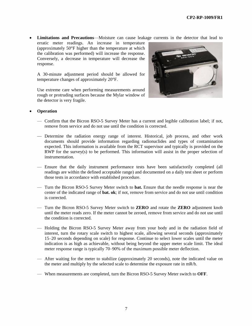
Limitations and Precautions—Moisture can cause leakage currents in the detector that lead to
erratic meter readings. An increase in temperature
(approximately 50°F higher than the temperature at which
the calibration was performed) will increase the response.
Conversely, a decrease in temperature will decrease the
response.
A 30-minute adjustment period should be allowed for
temperature changes of approximately 20°F.
Use extreme care when performing measurements around
rough or protruding surfaces because the Mylar window of
the detector is very fragile.
Operation
— Confirm that the Bicron RSO-5 Survey Meter has a current and legible calibration label; if not,
remove from service and do not use until the condition is corrected.
— Determine the radiation energy range of interest. Historical, job process, and other work
documents should provide information regarding radionuclides and types of contamination
expected. This information is available from the RCT supervisor and typically is provided on the
RWP for the survey(s) to be performed. This information will assist in the proper selection of
instrumentation.
— Ensure that the daily instrument performance tests have been satisfactorily completed (all
readings are within the defined acceptable range) and documented on a daily test sheet or perform
those tests in accordance with established procedure.
— Turn the Bicron RSO-5 Survey Meter switch to bat. Ensure that the needle response is near the
center of the indicated range of bat. ok; if not, remove from service and do not use until condition
is corrected.
— Turn the Bicron RSO-5 Survey Meter switch to ZERO and rotate the ZERO adjustment knob
until the meter reads zero. If the meter cannot be zeroed, remove from service and do not use until
the condition is corrected.
— Holding the Bicron RSO-5 Survey Meter away from your body and in the radiation field of
interest, turn the rotary scale switch to highest scale, allowing several seconds (approximately
15–20 seconds depending on scale) for response. Continue to select lower scales until the meter
indication is as high as achievable, without being beyond the upper meter scale limit. The ideal
meter response range is typically 70–90% of the maximum possible meter deflection.
— After waiting for the meter to stabilize (approximately 20 seconds), note the indicated value on
the meter and multiply by the selected scale to determine the exposure rate in mR/h.
— When measurements are completed, turn the Bicron RSO-5 Survey Meter switch to OFF.

CP2-RP-1009/FR1
8
2.2.2 Bicron RSO-50E Survey Meter
The Bicron RSO-50E Survey Meter is a self-contained
portable survey meter for measurements of exposure
rate and dose rate at medium to high beta and photon
radiation levels. The detector is an air-filled ionization
chamber, which is sensitive to beta radiation energy
above 70 keV and X-ray and gamma photons in the
energy range of approximately 40keV to 7 MeV.
The Bicron RSO-50E Survey Meter has an effective
measurement range of 0.5 milliroentgens/h (mR/h)-50
Roentgens/h (R/h). Ranges are: 0-50mR/h, 0-500mR/h,
0-5 R/h, and 0-50 R/h. ON-OFF, battery test, meter
zeroing, and four range selections are controlled by the
same rotary switch. Another control is a protected
ZERO adjustment knob used to adjust the meter to
zero. The housing provides a retractable beta particle
shield.
Applications
The Bicron RSO-50E Survey Meter is used to measure direct radiation levels in units of exposure
rate, i.e., milliroentgens/h (mR/h) and Roentgens/h (R/h). It can be used to determine area radiation
levels in the 0.5mR/h to 50 R/h range found at an isolated number of &R operations. The Bicron
RSO-50E Survey Meter is typically calibrated for accurate response at the Cs-137 gamma energy and
the beta energy for depleted uranium. Typically, a Beta Correction Factor - (BCF) will be identified
on the instrument calibration label. The Bicron RSO-50E Survey Meter will indicate relative radiation
levels and identify changes in radiation levels. The Bicron RSO-50E Survey Meter, because of the
detector's independence in energy response at varying energy fields, can be used for measurement of
radiation levels where activation and/or fission products are present.
Controls and Displays
— Bat—Power is provided by a 9-volt battery. There is an additional battery holder to
accommodate a spare. To test the battery level, the rotary switch is placed in the “bat.”
position, a response in the “bat. ok” range indicates that there is sufficient power to operate
the Bicron RSO-50E Survey Meter.
— ZERO—Placing the rotary switch in the ZERO position and adjusting the ZERO adjustment
knob adjusts the meter needle to zero on the display.
— SCALES—The four ranges are described in the General Description above.
— DISPLAY—All measurements and indication of battery tests are indicated on the single
analog meter display.

CP2-RP-1009/FR1
9
Additional Features and Auxiliary Equipment
— A lighted meter option is available for the Bicron RSO-50E Survey Meter. Built-in lights
illuminate the meter face when a pushbutton switch in the handle is depressed.
Limitations and Precautions
— Moisture can cause leakage currents in the detector that leads to erratic meter readings.
— An increase in temperature (approximately 50 F higher than the temperature at which the
calibration was performed) will increase the response. Conversely, a decrease in temperature will
decrease the response.
— A 30-minute adjustment period should be allowed for temperature changes of approximately
20oF. Use extreme care when performing measurements around rough or protruding surfaces
because the Mylar™ window of the detector is very fragile.
Operation
— Confirm that the Bicron RSO-50E Survey Meter has a current and legible calibration label; if not,
remove from service and do not use until the condition is corrected.
— Determine the radiation energy range of interest. Historical, job-process, and other work
documents should provide information regarding radionuclides and types of contamination
expected. This information is available from the Radiological Control Technician Supervisor and
is typically provided on the Radiation Work Permit for the survey(s) to be performed. This
information will assist in the proper selection of instrumentation.
— Ensure that the daily instrument performance tests have been satisfactorily completed (all
readings are within the defined acceptable range) and documented on a Daily Test Sheet or
perform those tests in accordance with established procedure.
— Tum the Bicron RSO-50E Survey Meter's rotary switch to bat. Ensure that the needle response is
near the center of the indicated range of “bat. ok”; if not, remove from service and do not use
until condition is corrected.
— Tum the Bicron RSO-50E Survey Meter's switch to ZERO and rotate the ZERO adjustment knob
until the meter reads zero. If the meter cannot be zeroed, remove from service and do not use until
the condition is corrected.
— Holding the Bicron RSO-50E Survey Meter away from your body and in the radiation field of
interest, tum the rotary scale switch to highest scale, allowing several seconds (approximately 15-
20 seconds depending on scale) for response. Continue to select lower scales until the meter
indication is as high as achievable without being beyond the upper meter scale limit.
— After waiting for the meter to stabilize (approximately 20 seconds), note the indicated value on
the meter and multiply by the selected scale to determine the exposure rate in mR/h or R/h, as
appropriate.
— When measurements are completed, tum the Bicron RSO-50E Survey Meter's switch to OFF.

CP2-RP-1009/FR1
10
2.2.3 Eberline RO-2 Survey Meter
The Eberline RO-2 Survey Meter is a self-contained portable
survey meter for measurements of exposure rate and dose
rate at medium to high beta and photon radiation levels. The
detector is an air-filled ionization chamber, which is
sensitive to beta radiation energy above 70 keV and X-ray
and gamma photons in the energy range of approximately
12 keV–7 MeV.
The Eberline RO-2 Survey Meter has an effective
measurement range of 0.5 mR/h to 5 R/h. Ranges are 0–5
mR/h, 0-50 mR/h, 0–500 mR/h, and 0–5,000 mR/h. On-Off,
battery test, meter zeroing, and four range selections are
controlled by the same rotary switch. A zero adjustment knob is provided for zeroing the meter needle.
The housing provides a retractable beta particle shield.
Applications—The Eberline RO-2 Survey Meter is used to measure direct radiation levels in units of
exposure rate (i.e., mR/h). It can be used to determine area radiation levels in the 0.5 mR/h–5,000
mR/h range found at some of &R operations. The Eberline RO-2 Survey Meter typically is calibrated
for accurate response at the Cs-137 gamma energy and the beta energy for depleted uranium.
Typically, a BCF will be identified on the instrument calibration label. The Eberline RO-2 Survey
Meter will indicate relative radiation levels and identify changes in radiation levels. The Eberline RO-
2 Survey Meter, because of the detector’s independence in energy response at varying energy fields,
can be used for measurement of radiation levels where activation and/or fission products are present.
Controls and Displays
— bat 1 and bat 2—Power is provided by two 9-volt batteries. To test the battery level, the rotary
switch is placed in the bat 1 and bat 2 positions; both responses above the bat cutoff line on the
display indicate that there is sufficient power to operate the instrument.
— Zero—Placing the rotary switch in the ZERO position and turning the ZERO adjustment knob,
adjusts the meter needle to ZERO on the display.
— Scales—The four ranges are described in the general description above.
— Display—All measurements and indication of batteries’ tests are indicated on the single analog
meter display.
There are no additional features or auxiliary equipment for the Eberline RO-2 Survey Meter.
Limitations and Precautions—Moisture can cause leakage currents in the detector that lead to
erratic meter readings. An increase in temperature (approximately 50°F higher than the temperature at
which the calibration was performed) will increase the response. Conversely, a decrease in
temperature will decrease the response.
A 30-minute adjustment period should be allowed for temperature changes of approximately 20°F.
Operation

CP2-RP-1009/FR1
11
— Confirm that the Eberline RO-2 Survey Meter has a current and legible calibration label; if not,
remove from service and do not use until the condition is corrected.
— Determine the radiation energy range of interest. Historical, job process, and other work
documents should provide information regarding radionuclides and types of contamination
expected. This information is available from the RCT supervisor and typically is provided on the
RWP for the survey(s) to be performed. This information will assist in the proper selection of
instrumentation.
— Ensure that the daily instrument performance tests have been satisfactorily completed (all
readings are within the defined acceptable range) and documented on a daily test sheet or perform
those tests in accordance with established procedure.
— Turn the Eberline RO-2 Survey Meter’s rotary switch to bat. Ensure that the needle response is
near the center of the indicated range of bat. ok; if not, remove from service and do not use until
condition is corrected.
— Turn the Eberline RO-2 Survey Meter’s switch to ZERO and rotate the ZERO adjustment knob
until the meter reads zero. If the meter cannot be zeroed, remove from service and do not use until
the condition is corrected.
— Holding the Eberline RO-2 Survey Meter away from your body and in the radiation field of
interest, turn the rotary scale switch to highest scale, allowing several seconds (approximately
15–20 seconds depending on scale) for response. Continue to select lower scales until the meter
indication is as high as achievable without being beyond the upper meter scale limit. The ideal
meter response range is typically 70–90% of the maximum possible meter deflection.
— After waiting for the meter to stabilize (approximately 20 seconds), note the indicated value on
the meter and multiply by the selected scale to determine the exposure rate in mR/h or R/h, as
appropriate.
— When measurements are completed, turn the Eberline RO-2 Survey Meter’s switch to OFF.
2.2.4 Eberline RO-20 Survey Meter
The Eberline RO-20 survey meter is a self-contained portable survey meter
for measurements of exposure rate at medium to high beta photon radiation
levels.
The detector is an air-filled ionization chamber that is sensitive to beta
radiation energy above 70 keV and X-ray and gamma photons in the energy
range of approximately 8 keV–1.3 MeV.
The Eberline RO-20 survey meter has an effective measurement range of
0.5 mR/h–50 R/h. Ranges are 0–5 mR/h, 0–50 mR/h, 0–500 mR/h, 0–5 R/h,
and 0–50 R/h. On-Off, batteries test, meter zeroing, and five range selections
are controlled by the same rotary switch.
A zero adjustment knob is provided for zeroing the meter needle.
A light switch is provided to illuminate the display. The housing provides a retractable beta particle
CP2-RP-1009/FR1
12
shield.
Applications—The Eberline RO-20 survey meter is used to measure direct radiation levels in units of
exposure rate (i.e., mR/h). It can be used to determine area radiation levels in the 0.5 mR/h to 50 R/h
range found at an isolated number of D&R operations. The Eberline RO-20 survey Meter typically is
calibrated for accurate response at the Cs-137 gamma energy and the beta energy for depleted
uranium. Typically, a BCF will be identified on the instrument calibration label. The Eberline RO-20
survey meter will indicate relative radiation levels and identify changes in radiation levels. The
Eberline RO-20 survey meter will indicate relative radiation levels and identify changes in radiation
levels. The Eberline RO-20 survey meter, because of the detector’s independence in energy response
at varying energy fields, can be used for measurement of radiation levels where activation and/or
fission products are present.
Controls and Displays
— Battery 1—Five standard C-size batteries provide power. Newer models have been upgraded to
be powered by five standard AA-size batteries. To test the battery level, the rotary switch is
placed in the Battery 1 position; response above the Battery Check cutoff line on the display
indicates that there is sufficient power to operate the Eberline RO-20 survey meter.
— Battery 2—Ten 3-volt lithium coin batteries provide power for the air chamber bias. Newer
models have been upgraded to be powered by three alkaline type MN21/23 batteries. To test the
battery level, the rotary switch is placed in the Battery 2’s position; response above the Battery
Check cutoff line on the display indicates that there is sufficient power to the chamber.
— Zero—Placing the rotary switch in the zero position and turn the zero adjustment knob to adjust
the meter needle to zero on the display.
— Scales—The five ranges are described in the general description above.
— Display—All measurements and indication of battery tests are indicated on the single analog
meter display.
Additional Features and Auxiliary Equipment—There are no additional features or auxiliary
equipment for the Eberline RO-20 survey meter.
Limitations and Precautions—Moisture can cause leakage currents in the detector that lead to
erratic meter readings. An increase in temperature (approximately 50°F higher than the temperature at
which the calibration was performed) will increase the response. Conversely, a decrease in
temperature will decrease the response.
A 30-minute adjustment period should be allowed for temperature changes of approximately 20°F.
Operation
— Confirm that the Eberline RO-20 survey meter has a current and legible calibration label; if not,
remove from service and do not use until the condition has been corrected.
— Determine the radiation energy range of interest. Historical, job process, and other work

CP2-RP-1009/FR1
13
documents should provide information regarding radionuclides and types of contamination
expected. This information is available from the RCT supervisor and typically is provided on the
RWP for the survey(s) to be performed. This information will assist in the proper selection of
instrumentation.
— Ensure that the daily instrument performance tests have been satisfactorily completed (all
readings are within the defined acceptable range) and documented on a daily test sheet or perform
those tests in accordance with established procedure.
— Turn the Eberline RO-20 survey meter’s rotary switch to Battery 1. Ensure that the needle
response is within the green arc on the display; if not, remove from service and do not use until
condition is corrected.
— Turn the Eberline RO-20 survey meter’s rotary switch to Battery 2. Ensure that the needle
response is within the green arc on the display; if not, remove from service and do not use until
the condition is corrected.
— Turn the Eberline RO-20 survey meter switch to zero and rotate the zero adjustment knob until
the meter reads zero. If the meter cannot be zeroed, remove from service and do not use until the
condition is corrected.
— Holding the Eberline RO-20 Survey Meter away from your body and in the radiation field of
interest, turn the rotary scale switch to highest scale, allowing several seconds (approximately
15–20 seconds depending on scale) for response. Continue to select lower scales until the meter
indication is as high as achievable without being beyond the upper meter scale limit. The ideal
meter response range is typically 70–90% of the maximum possible meter deflection.
— After waiting for the meter to stabilize (approximately 20 seconds), note the indicated value on
the meter and multiply by the selected scale to determine the exposure rate in mR/h or R/h, as
appropriate.
— When measurements are completed, turn the Eberline RO-20 survey meter switch to OFF.
2.3 HIGH DOSE RANGE BETA-GAMMA INSTRUMENTS
All instruments in this section have two
halogen quenched G-M tubes at the end of an
extended pole. The poles have extended
length range from 12–15 ft and are designed
to allow measurements of high dose rates at a
distance from the source for ALARA. A
larger G-M tube covers measurements to
50 mR/h or 100 mR/h. The small G-M tube
measures to 1,000 R/h.
The G-M tubes actually monitor secondary electrons emitted from the metal surrounding the tubes at the
end of the pole. Because of the thickness of the surrounding metal, the detector has more limited response
to lower energized and scattered photons. The G-M over-response in the 100 keV region is minimized;
however, there is a tendency for under-response to gamma rays with energies greater than those used for

CP2-RP-1009/FR1
14
calibration.
Slow response (tens of seconds) to a stabilized level of measurement can be expected and especially when
using the lowest ranges to measure several mR/h.
Both practice and extra care are required to safely use the extended poles.
2.3.1 Eberline 6112B Survey Meter
The Eberline Model 6112B Survey Meter is a telescoping survey meter for
measurements of exposure rate at medium to very high photon
radiation levels. The two detectors are energy compensated G-M
tubes, which are sensitive to X-ray and gamma radiation in the energy
range of 60 keV–3 MeV.
The Eberline Model 6112B Survey Meter has an effective measurement
range of 0–1,000 R/h. Ranges may be selected for both detectors. The low
range G-M detector ranges are 0–2 mR/h, 0–50 mR/h and
0–2 R/h. The high range G-M detector ranges are 0–50 R/h and 0–1,000 R/h. ON-OFF and
measurement range selections are controlled by the same rotary switch.
Applications—The Eberline Model 6112B Survey Meter is used to measure direct radiation levels in
units of exposure rate (i.e., R/h). It can be used to determine area radiation levels in the
200 mR/h–1,000 R/h range found at a number of &R operations. The Eberline Model 6112B Survey
Meter typically is calibrated for accurate response at the Cs-137 gamma energy. The Eberline Model
6112B Survey Meter will indicate relative radiation levels and identify changes in radiation levels.
The Eberline Model 6112B Survey Meter, because of the detector’s tendency to over respond at
lower photon energy fields, should not be used for measurement of radiation levels where activation
and/or fission products are present.
Controls and Displays
— bat.—Power is provided by four standard C-size batteries. To test the battery level, the rotary
switch is placed in the bat. position; response above the Battery Check cutoff line on the display
indicates that there is sufficient power to operate the Eberline Model 6112B Survey Meter.
— Scales—The five ranges are described in the general description.
— Display—All measurements and indication of battery test are indicated on the single analog
meter display.
— Additional Features and Auxiliary Equipment—There is an earphone connection to enable
monitoring an audible signal.
— Limitations and Precautions—Operation in the 0–200 mR/h range should be done allowing
approximately 10 seconds for the meter to fully respond.

CP2-RP-1009/FR1
15
Operation
— Confirm that the Eberline Model 6112B Survey Meter has a current and legible calibration label;
if not, remove from service and do not use until the condition is corrected.
— Determine the radiation energy range of interest. Historical, job process, and other work
document should provide information regarding radionuclides and types of contamination
expected. This information is available from the RCT supervisor and typically is provided on the
RWP for the survey(s) to be performed. This will assist in the proper selection of instrumentation.
— Ensure that the daily instrument performance tests have been satisfactorily completed (all
readings are within the defined acceptable range) and documented on a daily test sheet or perform
those tests in accordance with established procedure.
— Turn the Eberline Model 6112B Survey Meter’s rotary switch to bat. Ensure that the needle
response is within the green arc on the display; if not, remove from service and do not use until
the condition is corrected.
— While in a low radiation area, turn the Eberline Model 6112B Survey Meter’s switch to the
0–50 mR/h scale and observe the reading. If the meter is not at zero, remove from service and do
not use until the condition is corrected.
— Holding the Eberline Model 6112B Survey Meter in the radiation field of interest, turn the rotary
scale switch to highest scale allowing several seconds (approximately 15–20 seconds depending
on scale) for response. Continue to select lower scales until the meter indication is as high as
achievable without being beyond the upper meter scale limit. The ideal meter response range is
typically 70–90% of the maximum possible meter deflection.
— After waiting for the meter to stabilize (approximately 5–10 seconds), note the indicated value on
the meter and multiply by the selected scale to determine the exposure rate in mR/h or R/h, as
appropriate.
— When measurements are completed, turn the Eberline Model 6112B Survey Meter’s switch to
OFF.
2.3.2 Automess 6150 AD2 Survey Meter
The Automess 6150 AD 2 is a portable, battery-operated, dose-rate
meter that measure gamma and X-rays. A built-in GM counting tube
serves as the detector. It may be attached to external detectors.
As implied by the letters “AD” in its name, the 6150AD displays
dose rate in both analog and digital form. The display is a static
(non-multiplexed) liquid crystal display (LCD) and can be set to
indicate either R/h or Sv/h.

CP2-RP-1009/FR1
16
The dose rate indication is provided in both digital and analog form simultaneously. The analog scale
covers two decades and consists of 32 bar graph segments arranged in the shape of an arc. Two adjacent
ranges always overlap by one decade. The 6150 AD automatically switches ranges. A short sound calls
the user’s attention every time the range is changed.
The Automess 6150 AD 2 can
be attached to a telescoping
survey meter using two GM
detectors for measurements of
exposure rates at medium to
very high photon radiation
levels. The two detectors are
energy compensated G-M
tubes which are sensitive to X-
ray and gamma radiation in the
energy range of 45keV to 3.0
MeV. This two-detector
arrangement has a useful range
of 0.2 mR/h to 999 R/h.
Applications—The Automess 6150 AD 2 Survey Meter is used to measure direct radiation levels in
units of exposure rate (i.e., R/h). It can be used to determine area radiation levels in the
200 mR/h–1,000 R/h range found at a number of &R operations. The Automess 6150 AD 2 Survey
Meter is typically calibrated for accurate response at the Cs-137 gamma energy. The Automess 6150
AD 2 Survey Meter will indicate relative radiation levels and identify changes in radiation levels. The
Automess 6150 AD 2 Survey Meter, because of the detector’s tendency to over respond at lower
photon energy fields, should not be used for measurement of radiation levels where activation and/or
fission products are present.
Controls and Displays
— Bat.—Power is provided by a single 9-volt battery. Battery voltage will be indicated when the
instrument is switched on. Using the arrow button (see picture above), the “Battery Voltage and
Battery Monitoring” function can be selected to view the voltage of the 9-volt battery at any time.
Voltages below 5.5 volts produce a battery warning consisting of the flashing battery symbol in
the upper right corner of the LCD and a continuous alarm tone. Pressing the loudspeaker key will
cut out the alarm tone and make the battery symbol appear steadily. This automatic battery
warning is issued in any state of the Automess 6150 AD 2.
— Scales—The Automess 6150 AD 2 automatically selects the appropriate range/scale. The LCD
displays the scale being used.
— Display—All measurements and indication of battery test are indicated on the LCD display.

CP2-RP-1009/FR1
17
— Additional Features and Auxiliary Equipment—Connecting an external probe disconnects the
internal probe and makes the probe type appear in the upper left corner of the LCD. Ranges and
units are selected automatically. Dose rate indication is the ground state. Pressing the arrow key
allows the user to toggle between other states.
– Dose Rate Average Value—The dose-rate average value is particularly useful at low dose
rates where direct dose-rate indication is subject to strong statistical fluctuations. The digits
will flash as long as the statistical error is greater than 5%.
– Viewing and Setting the Dose Rate Alarm Threshold—The loudspeaker key allows the user
to select a threshold from a set of fixed values.
– Dose Rate Maximum Value—The >>max<< symbol shows that this indication concerns the
maximum dose rate value since the instrument was switched on.
– Battery Voltage and Battery Monitoring—This function allows the user to view the battery
voltage at any time.
— Limitations and Precautions—When operating in the 0–200 mR/h range, allow approximately
2–8 seconds for the meter to fully respond.
Operation
— Confirm that the Automess 6150 AD 2 Survey Meter has a current and legible calibration label; if
not, remove from service and do not use until the condition is corrected.
— Determine the radiation energy range of interest. Historical, job process, and other work
document should provide information regarding radionuclides and types of contamination
expected. This information is available from the RCT supervisor and typically is provided on the
RWP for the survey(s) to be performed. This will assist in the proper selection of instrumentation.
— Ensure that the daily instrument performance tests have been satisfactorily completed (all
readings are within the defined acceptable range) and documented on a daily test sheet or perform
those tests in accordance with established procedure.
— Press the Automess 6150 AD 2 Survey Meter’s power button. Ensure the battery indicates greater
than 5.5 volts on the LCD; if not, remove from service and do not use until the condition has been
corrected.
— Holding the Automess 6150 AD 2 Survey Meter in the radiation field of interest, observe the
LCD display allowing several seconds (approximately 2–8 seconds) for an accurate response.
— After waiting for the meter to stabilize (approximately 2–8 seconds), note the indicated value on
the meter.
— When measurements are completed, depress the Automess 6150 AD 2 Survey Meter’s power
button to turn the instrument OFF.

CP2-RP-1009/FR1
18
2.4 NEUTRON SURVEY INSTRUMENTS
Neutrons do not cause ionization directly. Both the measurement of neutrons and the radiation dose
interactions due to neutrons are a consequence of secondary emissions from neutron reactions.
For example, neutrons interact with the boron in the boron trifluoride (BF3) detectors used in many
instruments. The reaction is as follows:
10
B (n,α) 7Li
The BF3 detectors are proportional counters and respond to the liberated alpha particle and the lithium-7
recoil nucleus. The relatively large pulse heights allow for good rejection of the small pulses due to
gamma rays; however, this reaction is very energy dependent and is most probable with very low (thermal
and epi-thermal) neutron energies. That is, energies ranging from less than one electron volt to several
electron volts.
The neutron dose to soft tissue primarily is due to recoil or scatter protons and recoil nuclei when
neutrons interact with nuclei of hydrogen, carbon, oxygen, and nitrogen atoms in tissue.
These interactions essentially don’t happen with low energy neutrons and aren’t important until neutron
energies exceed several hundred keV.
For health physics applications, virtually all neutron fields have a broad range of neutron energies
covering seven or eight orders of magnitude. It is difficult to produce a monoenergetic neutron beam.
With any neutron source there is always a large amount of neutron scattering that broadens the scope of
neutron energies with a neutron field.
To improve the detector response to better relate the measurement to dose, the BF3 detectors are
surrounded with neutron moderators that cut off the low energy neutrons and slow down the higher
energy neutrons. The spherical moderators also have an internal spherical shell of cadmium to capture
low energy neutrons. The size of the sphere and the location of the cadmium shell were designed to
provide near equivalent dose response to fission spectrum neutrons. That spectrum ranges from very low
to relatively high-energy neutrons with a mode of about 2.5 MeV.
The tissue equivalent proportional counter (TEPC) detector responds to recoil protons and recoil nuclei.
The detector shell and fill gas have low atomic number elements to mimic the kind of neutron interactions
that occur in tissue. For this reason, the TEPC provides the best measurement of neutron dose rate that is
relatively independent of the neutron energy spectrum. The TEPC often is used as a secondary standard to
measure neutron dose with varying, or unqualified, neutron energy spectra.
Accurate characterization of the neutron energies in a specific field requires the use of various sized
moderators and a computer program to unfold the spectrum; however, the neutron scatter can change over
short distances, and one spectrum does not cover an entire controlled area. For example, the scatter of
neutrons and the energy spectrum near UF6 cylinders will vary depending upon scatter conditions at any
specific location.

CP2-RP-1009/FR1
19
2.4.1 Eberline E-600 Ratemeter/Scaler
The Eberline E-600 ratemeter/scaler provides the required microprocessor
and electronic circuitry for neutron radiation monitoring with a neutron
rem detector (NRD). The E-600 is preprogrammed for the NRD detector.
The detector is a boron trifluoride proportional detector surrounded by a
9-inch diameter polyethylene cadmium loaded sphere for use as an area
monitor. The detector is sensitive to neutron radiation in the range of
25 keV–10 MeV [typically, response is approximately 50 counts per
minute (cpm)/mrem/h].
The Eberline E-600 ratemeter/scaler has an effective measurement range
of 0–10 rem/h. A rotary switch provides for on-off, alarm set point check,
background accumulation, and selection for the four operating modes:
Ratemeter, Integrate, Peak-Trap, and Scaler. Ranges are set automatically
by preprogramming the E-600. Readings are displayed on a 0–1 scale and
a 0–1,000K range. Push button switches are provided for “RANGE-UP/RANGE-DOWN” and
“GROSS/NET.” Push button switch functions are described in the Controls and Display section of this
procedure.
The Eberline E-600 ratemeter/scaler is powered by three standard C-size batteries.
Applications—The Eberline E-600 ratemeter/scaler is used to measure neutron radiation levels in
units of dose rate (i.e., mrem/h and rem/h). It can be used to determine neutron radiation levels in the
1.0 mrem/h–10 rem/h range. The Eberline E-600 ratemeter/scaler typically is calibrated for rejection
of gamma radiation at the Cs-137 gamma energy range, in a 10 R/h field; high voltage is reduced to
below the energy response for Cs-137 gamma energy field. The Eberline E-600 ratemeter/scaler will
indicate relative radiation levels and identify changes in radiation levels. The Eberline E-600
ratemeter/scaler, because of the detector’s proportional energy response, can be used for measurement
of radiation levels where activation and/or fission products are present.
Controls and Displays
Operating Mode Selections:
— Integrate—When the rotary switch is place in the INTEGRATE
position, measurements are displayed and integrated over a
preprogrammed time period.
— Peak-Trap—When the rotary switch is placed in the PEAK-
TRAP position, the instrument displays an instantaneous
measurement for evaluation.
— Ratemeter—When the rotary switch is placed in the
RATEMETER position, the instrument is operating as a rate
meter and this mode is indicated on the display.
— Scaler—When the rotary switch is placed in the SCALER
position, the instrument is operating as a scaler, and this mode is
indicated on the display.

CP2-RP-1009/FR1
20
Function Selections:
— Backgd—When the rotary switch is placed in the BACKGD position, background subtraction is
set at the value in the E-600 memory.
— Check—When the rotary switch is placed in the CHECK position, the alarm set points are
displayed, pressing the “*” allows editing of the alarm set points.
— Chnl—When this push button is depressed, the Eberline E-600 ratemeter/scaler shifts to the next
preprogrammed discriminator channel.
— Gross/Net—When this push button toggle switch is depressed, the background data is not
subtracted (GROSS) or the background data is subtracted (NET) on the display.
— LED—The light emitting diode (LED) provides visual indication of an alarm condition.
— Light—When this push button is depressed, the display is illuminated for approximately five
seconds.
— Log—When this push button is depressed, the displayed measurement is placed in the Eberline
E-600 Ratemeter/Scaler’s memory.
— Range Up/Range Down—When this push button toggle switch is depressed, the full-scale range
is increased/decreased by a factor of 10 on the display.
— Spkr—When this push button toggle switch is depressed, the audible signal is on or off.
Additional Features and Auxiliary Equipment—There are a variety of detectors that are
compatible with the E-600. An interface computer program is available for configuring the Eberline
E-600 Ratemeter/Scaler. A bar code reader is available for use with this instrument.
Limitations and Precautions—Do not rely on the audible signal for warning of increasing radiation
levels. The Eberline E-600 ratemeter/scaler is portable and it weighs approximately 18 pounds; take
the necessary precautions to prevent personal injury when lifting and carrying this instrument.
Operation
— Confirm that the Eberline E-600 ratemeter/scaler has a current and legible calibration label; if not,
remove from service and do not use until the condition is corrected.
— Determine the radiation energy range of interest. Historical, job process, and other work
documents should provide information regarding radionuclides and types of contamination
expected. This information is available from the RCT supervisor and typically is provided on the
RWP for the survey(s) to be performed. This will assist in the proper selection of instrumentation.
— Ensure that the daily instrument performance tests have been satisfactorily completed (all
readings are within the defined acceptable range) and documented on a daily test sheet or perform
those tests in accordance with established procedure.
— Turn the Eberline E-600 ratemeter/scaler’s rotary switch to the ON position.

CP2-RP-1009/FR1
21
— If the message “FAIL” is visible on the Eberline E-600 ratemeter/scaler’s display, remove from
service and do not use until the condition is corrected.
— Ensure that the OUT-OF-CAL message is not visible on the display; if displayed, remove from
service and do not use until the condition is corrected.
— Ensure that PROBE FAIL message is not visible on the display; if displayed, remove from
service and do not use until the condition is corrected.
— Ensure that the HV (high voltage), message is visible on the display; if displayed, remove from
service and do not use until the conditions is corrected.
— Ensure that the “FAIL,” instrument failure icon, is not visible on the display; if displayed, remove
from service, and do not use until condition is corrected.
— Turn the Eberline E-600 ratemeter/scaler’s rotary switch to the CHECK position.
— Ensure that the BATTERY icon is not visible on the display; if displayed, remove from service,
and do not use until the condition is corrected.
— Depress the CHNL push button switch.
— Ensure that display indicates the instrument is connected to an NRD detector; if not, remove from
service and do not use until the condition has been corrected.
— Turn the Eberline E-600 ratemeter/scaler’s rotary switch to the RATEMETER position.
— Turn the Eberline E-600 ratemeter/scaler’s rotary switch to Battery 2. Ensure that the needle
response is within the green arc on the display; if not, remove from service and do not use until
the condition is corrected.
— Turn the Eberline E-600 ratemeter/scaler’s switch to ZERO-labeled switch and rotate the ZERO
adjustment knob until the meter reads ZERO. If the meter cannot be zeroed, remove from service
and do not use until the condition is corrected.
— Place the Eberline E-600 ratemeter/scaler on a sturdy surface and in the radiation field of interest,
turn the rotary scale switch to highest scale allowing several seconds (approximately 15–20
seconds depending on scale) for response. Continue to select lower scales until the meter
indication is as high as achievable without being beyond the upper meter scale limit.
— After waiting for the meter to stabilize (approximately 5 seconds), note the indicated value on the
meter and multiply by the selected scale to determine the exposure rate in mR/h or R/h, as
appropriate.
— When measurements are completed, turn the Eberline E-600 Ratemeter/Scaler’s switch to OFF.

CP2-RP-1009/FR1
22
2.4.2 Eberline ASP-2/2E
The Eberline ASP-2/2E is a general purpose portable radiation
meter controlled entirely by its microprocessor. The Eberline
ASP-2/2E may be in a wide range of detector configurations.
Both versions provide ratemeter measurements, alarm and
over-range indications, three response time settings, and clear
displays of measurement units and the type of radiation being
measured. The ASP-2/2E measures integrated dose and scaler
counts, as well as a pulse height window for
energy-proportional probes. The ASP2/2E has a power supply
range of 300 to 2500 volts and detection thresholds of 0.5 to 60
millivolts.
The ASP-2/2E is typically calibrated with an NRD. The
detector is a boron trifluoride proportional detector surrounded
by a 9-inch diameter polyethylene cadmium loaded sphere for
use as an area monitor. The detector is sensitive to neutron radiation in the range of 25 keV–10 MeV.
The ASP2/2E is powered by three standard alkaline “C” cells, with a typical battery life of 100 hours.
Applications—The Eberline ASP-2/2E is used to measure neutron radiation levels in units of dose
rate (i.e., mrem/h and rem/h). It can be used to determine neutron radiation levels in the 1.0 mrem/h–
10 rem/h range. The Eberline ASP-2/2E typically is calibrated for rejection of gamma radiation at the
Cs-137 gamma energy range, in a 10 R/h field; high voltage is reduced to below the energy response
for Cs-137 gamma energy field. The Eberline ASP-2/2E will indicate relative radiation levels and
identify changes in radiation levels. Because of the detector’s proportional energy response, this
instrument can be used for measurement of radiation levels where activation and/or fission products
are present.
Controls and Displays
— Check—When the rotary switch is placed in the Check position, the model and serial numbers of
the probe for which the instrument has been configured will scroll across the center of the display
until the “*” (Star Key) is pressed or another mode is
selected. Allows the customization of many instrument
parameters. Instrument parameters will be adjusted by the
Instrument Group with direction from the Instrument Group
RPPM and RCT Supervisor.
— Integrate—When the rotary switch is placed in the
Integrate position, measurements are displayed and
integrated over a preprogrammed time period. If an alarm
limit has been specified, an alarm indication is posted when
the alarm limit is exceeded. The Star Key may be used to
silence the audible alarm.
— Ratemeter—When the rotary switch is placed in the
Ratemeter position, the instrument is operating as a ratemeter. Units are displayed in the units
specified as one of the channel parameters. A rate alarm limit may be used in this mode.

CP2-RP-1009/FR1
23
— Scaler—When the rotary switch is placed in the Scaler position, the instrument is operating as a
scaler. In the scaler position, a new count cycle is performed by pressing the Star Key.
— Response—The user may step through slow, medium, and fast display response times. The actual
time constraints for each switch position are defined in probe memory to ensure that each switch
position represents an appropriate value for the type of probe in use.
— Speaker—Toggles the audible clicks for individual count events on or off.
— Light—When this button is pressed, the mechanical meter will be illuminated for five seconds.
The LCD is NOT illuminated. Continually pressing of this button will cause a substantial amount
of battery life to be used.
— Main—Selects the main counting channel.
— Star Key—Performs a wide variety of function as determined by the software used by the
ASP-2/2E depending upon the mode in which it is used. See ASP-2/2E user’s manual for further
information. Silences audible alarms.
— PHA (pulse height analysis)—Selects the PHA counting channel.
— Range—Increase and decrease full-scale range of the display by a factor of ten.
Note that all functions controlled by push buttons occur after the button is released.
Additional Features and Auxiliary Equipment
— The ASP-2/2E can be used with a wide variety of detectors. Configuration options can be
changed via a host program which runs on a personal computer.
— A wide variety of parameters, such as scaler count times and alarm settings, can be customized
depending upon job requirements/conditions. Instrument parameters will be adjusted by the
Instrument Group with direction from the Instrument Group RPPM and RCT Supervisor.
Limitations and Precautions
— Connecting the incorrect probe to the instrument will almost certainly lead to inaccurate readings
and may damage or destroy the probe.
— Do not rely on the audible signal for warning of increasing radiation levels. The ASP-2/2E is
portable and it weighs approximately 18 pounds; take the necessary precautions to prevent
personal injury when lifting and carrying this instrument.
— The power supply of the ASP-2/2E produces up to 2,500 volts and may hold a dangerous charge
for up to one minute after the board is powered off. Avoid contact with the probe connector.

CP2-RP-1009/FR1
24
Operation
— Determine the radiation energy range of interest. Historical, job process, and other work
documents should provide information regarding radionuclides and types of contamination
expected. This information is available from the RCT supervisor and typically is provided on the
RWP for the survey(s) to be performed. This will assist in the proper selection of instrumentation.
— Confirm that the instrument in calibration by checking the calibration label.
— Turn the ASP-2/2E’s switch to the “Check” position. If the model and/or serial number do not
match the calibration label, then tag the instrument “out of service” and notify the Instrument
Group RCT Supervisor.
— While the switch is in the “Check” position, the BATTERY icon is turned on to identify the
display and voltage is presented as a percentage on the small numeric field in the lower right
corner of the display. A reading of 100% indicates a new set of batteries; 0% means that there is
little of no energy available. Batteries are temperature sensitive; new batteries may indicate
< 100% if they are very cold. Battery life percentages may vary due to the variations in battery
brands, even when new. It is advisable to replace the batteries soon after the battery icon first
appears during normal use.
— Ensure that the daily instrument performance tests have been satisfactorily completed (all
readings are within the defined acceptable range) and documented on a daily test sheet or perform
those tests in accordance with established procedure.
— Place the ASP-2/2E on a sturdy surface and in the radiation field of interest, turn the switch to the
appropriate position, either Ratemeter or Scaler.
– If the ASP-2/2E is being used as a “Ratemeter” allow several seconds for the instrument to
stabilize before recording a response.
– If the ASP-2/2E is being used as a “Scaler”, the Star Key is setup for a one minute count.
Pressing the Star Key will begin a new one-minute count cycle.
— When survey measurements are completed, turn the Eberline ASP-2/2E switch to Off.
2.5 DOSIMETERS
2.5.1 Canary III Electronic Pocket Dosimeter
The Canary III Dosimeter is an electronic personnel dosimeter that measures integrated dose in mR. The
instrument is small, light, and rugged. It has a variable beeper, variable integrated alarm, 2,000-hour
battery life from two BR2325 lithium batteries, memory feature, and a 6-digit display.
The dosimeter is capable of measuring accumulated dose over the following ranges:
Dose rate—background to 100 R/h
Accumulated dose—background to 999,999 mR

CP2-RP-1009/FR1
25
The Canary III employs an energy corrected PIN diode detector with the following response
characteristics:
Exposure Rate Response—15% from 1 mR to 100 R/h
Background—less than 0.1 mR/h
Accuracy—20% from 1 mR/h to 1 R/h
Energy Dependence—30% from 80 keV–1.25 MeV
Temperature Dependence—20% from 0°C to 50°C
The beeper may be set to beep every preset interval. An integrated dose alarm also
may be set to the values below. The 0.1 mR setting is approximate. The settable
intervals are these:
0.1, 1, 2, 4, 8, 16, 32, 64, 128, 256, 512, 1024, 2048 mR, and OFF.
The Canary III can be set internally to keep the display on all the time, even when the
instrument has been turned off. This retains the display of the last accumulated dose
until the unit is turned on again which will reset the display to zero.
Applications—The Canary III Dosimeter may be worn by radiation workers
engaged in tasks that require direct and frequent monitoring of accumulated dose
and/or significant changes in dose rate to help ensure that prescribed individual
radiation dose limits are not exceeded. This type of dosimeter is preferable to
standard direct reading “pencil dosimeters” because of its capability of chirping as dose is
accumulating, displaying accumulated dose and the preset alarm features.
Controls and Displays
— Battery Test Button—Press the BATT TEST button on top to check the battery. If the battery is
good, the beeper will beep. If the beeper battery is low, it will not beep at all. If the beeper
warbles, the beeper has at least 8 hours remaining on the battery.
— LCD Display—Up to 6 digits (999,999) are displayed in mR on LCD display located on the front
of the dosimeter.
— The scales are printed along the bottom of the display screen. If the readout is 235, this equals
2.35 m/R (2 positioned in the 1 scale, 3 positioned in the .1 scale, and 5 positioned in the .01
scale).
— On Button—The switch on the top should be turned in the direction of the arrow to turn the
instrument on.
Additional Features and Auxiliary Equipment—None.
Limitations and Precautions—The Canary III Dosimeter should be worn in a chest-area pocket;
there should be no other metal objects in the pocket, which might shield the dosimeter from radiation.
Microwaves and radio frequencies may cause erratic responses in these instruments. Avoid placing
the dosimeters in close proximity to microwave sources (e.g., microwave ovens), and do not key two-
way radios when they are within 30 cm or less of the dosimeters.

CP2-RP-1009/FR1
26
Operation—Because of the internal controls of the Canary III Dosimeter, maintenance and alarm
setup should be performed by the instrument group staff. The following describes the operation of the
Canary III Dosimeter that has been set up and configured for field applications by the instrument
group staff.
— Confirm that the Canary III Dosimeter has a current and legible calibration label; if not, remove
from service and do not use until the condition is corrected. Check the alarm settings against the
applicable RWP. Check for obvious physical damage.
— Turn the beeper on by turning the switch on the top marked ON in the direction of the arrow.
Check battery condition by pushing the BATT TEST button on top to check the battery. If the
battery is good the beeper will beep.
— Depending on configuration, the dosimeter may continue to display dose or may reset dose to
zero each time the Canary III Dosimeter is switched into the “measurement” mode. If a change in
this or any other configuration is desired, return it to the instrument group.
— After Canary III Dosimeter use, record the accumulated dose on the appropriate log sheet, and
turn the beeper off by turning the switch on the top marked ON away from the direction of the
arrow.
2.5.2 MGP Instruments DMC 2000 S Electronic Dosimeter
The DMC 2000 S Electronic Dosimeter is a small, compact, and
lightweight microprocessor-controlled personal radiation
monitor. The dosimeter unit contains an energy compensated
silicon diode detector for measuring gamma and X-ray radiations
in the energy range of 60 keV–6 MeV, electronic circuitry for
processing and storage of data, real-time digital display, user-
selected alarms, and other functions. The dosimeter is capable of
measuring equivalent dose rate and accumulated equivalent dose
for the following ranges:
Equivalent dose rate—background to 1,000 rem/h
Accumulated equivalent dose—background to 1,000 rem
Energy response is better than ± 30% for penetrating (“deep” or
“whole body”) Hp (10) equivalent dose and equivalent dose rate
in the energy range of 60 keV–2 MeV. Ranges and units are selected and displayed automatically on the
LCD display. Calibration is for Cs-137 gamma radiation with accuracy of better than ± 30% across the
entire dose and dose-rate range. The dosimeter also monitors exposure time and manages and monitors
other operational status parameters. Audible alarms alert the user to radiation conditions. Two thresholds
(alarm and pre-alarm) for accumulated dose and dose rate are adjustable over the entire measurement
range. Pre-alarm is a warning level and can be terminated by acknowledging the alarm. Power is provided
by a 3-volt LiMnO2 battery.
Applications—The DMC 2000 S Electronic Dosimeter may be worn by radiation workers engaged
in tasks that require direct and frequent monitoring of accumulated equivalent dose and/or significant
changes in equivalent dose rate to help ensure that prescribed individual radiation dose limits are not
CP2-RP-1009/FR1
27
exceeded. This type of dosimeter is preferable to standard direct reading “pencil dosimeters” because
of its capability of displaying dose rate and the preset alarm features.
Controls and Displays
— Selector Button—All functions of the dosimeter are controlled by this button switch. This
includes power on/off, battery test, display mode selection (dose/dose rate), selection of audible
feature, dose rate, and prealarm and alarm setting selection. Various commands and features are
determined by the length of time the button is depressed and the sequence of menu-driven switch
operations.
— LCD Display—All dosimeter conditions and readouts are displayed on the LCD display located
at the top of the dosimeter.
Additional Features and Auxiliary Equipment—The DMC 2000 S Electronic Dosimeter can be
operated in an “autonomous” mode (i.e., as an individual or independent unit) or in a “satellite” mode
(i.e., connected through a LDM101 dosimeter reader to a host IBM-compatible personal computer
with appropriate software). In the satellite mode, the dosimeter is inserted into a slot in the reader case
and the reader receives information from the dosimeter via an optical data port and relays that
information to the computer through a RS-232 cable. The LDM101 contains an “EPROM” chip for
storage of operating parameters and data. In the satellite mode, the computer performs the start-up
procedure; whereas, for operation in the autonomous mode, the initial configuration generally is
performed by the manufacturer.
Limitations and Precautions—The DMC 2000 S Electronic Dosimeter should be worn in a chest-
area pocket; there should be no other metal objects in the pocket, which might shield the dosimeter
from radiation.
Operation—Because of the intricacy of the DMC 2000 S Electronic Dosimeter, maintenance and
initial setup of DMC 2000 S dosimeters and the LDM101 dosimeter reader should be performed by
the instrument group following manufacturer’s direction. The following describes the operation of the
pre-initialized and configured dosimeter for field applications.
— Confirm that the DMC 2000 S Electronic Dosimeter has a valid and legible calibration label; if
not, remove from service and do not use until the condition is corrected.
— Determine the radiation energy range of interest. Historical, job process, and other work
documents should provide information regarding radionuclides and types of contamination
expected. This will assist in the proper selection of instrumentation.
Autonomous Mode Use—The DMC 2000 S Electronic Dosimeter will normally be in the “pause”
mode; a flashing colon and the word, “PAUSE” will be displayed indicating the dosimeter is
functioning.
Press the Selector button once. The display will indicate “CHANGE” for approximately 3 seconds,
then display “: Enter” for about 2 seconds, and finally, display “: In.” At this time, the DMC 2000 S
Electronic Dosimeter emits a beep, the red LED flashes, and a display test is automatically
performed. The DMC 2000 S Electronic Dosimeter is now in the “measurement” mode and is
operational; functional indicators will be flashing and the dose value is displayed, preceded by the
message, “dHP.”

CP2-RP-1009/FR1
28
The DMC 2000 S Electronic Dosimeter continuously measures and displays accumulated equivalent
dose (referred to as dose in the following guidance). Press and release the Selector button once to
display the dose rate. After about 30 seconds, the accumulated dose is again displayed.
Alarms and prealarm thresholds can be viewed by pressing the Selector button for at least 10
seconds. The thresholds will be alternately displayed every 2 seconds while the button is pressed.
Thresholds are displayed in scientific notation. Releasing the Selector button returns the display to
accumulated dose.
Depending on configuration, the dosimeter may continue to accumulate dose or may reset dose to
zero each time the DMC 2000 S Electronic Dosimeter is switched into the “measurement” mode. If a
change in this or any other configuration is desired, return it to the instrument group.
After DMC 2000 S Electronic Dosimeter use, deactivate the dosimeter by returning it to the “pause”
mode by depressing the Selector button for about 10 seconds. The display will indicate “CHANGE”
followed by “G: O OUT”; immediately release the Selector button. The message “: OUT” will be
displayed briefly. The dosimeter now is deactivated.
Satellite Mode Use—If the LDM101 reader is being used, connect the reader to the host computer;
connect the DC power supply to the reader and to an AC power outlet. Turn the reader on using the
rocker switch at the back of the instrument. The unit will perform a self-test, the buzzer will sound,
and LEDs will stay lit for about 4 seconds. Insert the DMC 2000 S Electronic Dosimeter into the slot
in the reader. Start the computer software program and set parameters following guidance in the
reader. Start the computer software program and set parameters following guidance in the software
user’s guide. Operations are controlled by the reader/computer system.
Calibration—Calibrations will be performed by a qualified vendor. Semiannual calibrations shall be
performed when the DMC 200S is used for criticality purposes. An annual calibration is required for
all other uses. Recalibration is required after maintenance or repair that would void the calibration.
Battery changes do not require recalibration.
Performance Checks—Performance of self-checks will be in accordance with manufacturer’s
specifications.
Training—Individuals issuing and/or performing setup of the DMC 2000 S shall have a signed Job
Performance Measure prior to issuance or setup.
2.5.3 Siemens EPD Mk2 Personal Electronic Dosimeter
The Siemens EPD Mk2 Personal Electronic Dosimeter is a small,
battery-powered personal radiation monitor. The unit contains three
silicon diode detectors shielded to enable the dosimeter to
differentiate radiation type and energy and electronic circuitry to
process the signals from the detector. The Siemens EPD Mk2
Personal Electronic Dosimeter is capable of measuring dose
equivalent rate and accumulated dose equivalent from radiations in
the following energy range:
Gamma, X-rays-15keV to 10MeV
Beta radiation-250keV to 1.5MeV (average energy)

CP2-RP-1009/FR1
29
Assembly—Dose equivalent is displayed on the LCD display for penetrating (“deep” or “whole
body”) and shallow (“superficial” or “skin”) as defined by ICRU-47 for Hp (10) and Hp (0.07),
respectively. The Siemens EPD Mk2 Personal Electronic Dosimeter has an effective accumulated
dose range of Omrem-1600rem and a dose rate range of Omremlh-400remlh. Display units of rem or
Sievert are internally selected during configuration. After initial configuration, units are selected and
displayed automatically. Calibration is for Cs-137 gamma radiation with accuracy of better than ±
10% across the entire dose and dose-rate range. The Siemens EPD Mk2 Personal Electronic
Dosimeter also monitors exposure time, manages, and monitors other operational status parameters.
Audible and visual alarms alert the user to radiation conditions. Two alarm points, adjustable using
the over the entire measurement range, are available for Hp (10) dose and dose rate. One alarm setting
is available for Hp (0.07) dose and for Hp (0.07) dose rate; these are adjustable over the dose and
dose rate ranges of Omrem-1600rem and 0.7mrem/h-1600rem/h, respectively. A 3-volt LiMnO2
battery, a 1.5-volt “AA” alkaline or 1.5-volt “AA” lithium cell battery provides power.
EPD Mk2 functions include an “EPROM” for internal storage of data; an audible and visual LED
alarm, activated at a preset rate or accumulation; and an infrared (IR) communication interface for
remote dosimeter readout and to facilitate setting various functions and parameters.
Applications—The Siemens EPD Mk2 Personal Electronic Dosimeter may be worn by radiation
workers engaged in tasks that require direct and frequent monitoring of accumulated dose equivalent
and/or significant changes in dose equivalent rate to help assure that prescribed individual radiation
dose limits are not exceeded. The Siemens EPD Mk2 Personal Electronic Dosimeter is preferable to
standard direct reading “pencil dosimeters” because of its capability of displaying dose rate, its ability
to measure mixed fields of low and high-energy photons and beta radiation, and the preset alarm
features.
The IR communications feature allows the dose and dose rate received by the EPD to be remotely
monitored and stored, thus permitting close oversight without added unnecessary exposure.
Controls and Displays
— SELECTOR BUTTON—All functions of the dosimeter are controlled by this button switch.
This includes power ON/OFF, configuration test, battery test, display mode selection (dose/dose
rate), selection of audible feature, dose reset, and pre-alarm and alarm setting selection. The
length of time and the number of times the button is depressed and the sequence of menu-driven
switch operations determine various commands and features.
— LCD DISPLAY—All dosimeter conditions and readouts are displayed on the LCD display
located on top of the dosimeter.
— LED—The LED provides visual indication of an alarm condition.
— SOUNDER—Provides an audible indication of an alarm condition.
Additional Features and Auxiliary Equipment—The Siemens EPD Mk2 Personal Electronic
Dosimeter can be operated as an individual (stand-alone) unit or as part of a dosimetry system
through a readerlPC. In the latter mode, data may be written to and read from the EPD via an infrared
communications interface. This communication requires a software program, such as “EasyEPD2.”
This reader is required for configuration or re-configuration of certain EPD parameter settings (e.g.,
alarm thresholds, dose/dose rate units, and readout of accumulated data files).

CP2-RP-1009/FR1
30
Limitations and Precautions—The Siemens EPD Mk2 Personal Electronic Dosimeter should be
worn in a chest-area pocket; there should be no other metal objects in the pocket, which might shield
the dosimeter from radiation.
The lithium thionyl chloride battery is potentially toxic, flammable, and explosive. These batteries
must be handled using gloves and eye protection. Wash areas of skin contact with battery contents
using copious amounts of water. Follow manufacturer's and D&R Industrial Hygienist's (ill) direction
in handling, packaging, and disposal of these batteries.
The EPD may alarm because of non-ionizing radiations from sources, such as microwave generators,
radio repeater stations, and other communications devices.
Operations—Because of the intricacy of the Siemens EPD Mk2 Personal Electronic Dosimeter,
maintenance and initial setup of EPD Mk2 dosimeters, changes in configuration, alarm settings,
special applications and features, and use of the dosimeter with the reader PC should be performed by
or under direction of the Instrumentation Organization staff following manufacturer's direction. The
following describes the operation of the pre-initialized and configured dosimeter for typical field
applications.
— Confirm that the Siemens EPD Mk2 Personal Electronic Dosimeter has a current and legible
calibration label; if not, remove from service and do not use until the condition is corrected.
— Determine the radiation energy range of interest. Historical data, job-process, and other work
documents should provide information regarding radionuclides and types of contamination
expected. This information is available from the Radiological Control Technician Supervisor and
is typically provided on the Radiation Work Permit for the survey(s) to be performed. This will
assist in the proper selection of instrumentation.
— Confirm that the Siemens EPD Mk2 Personal Electronic Dosimeter's calibration is current.
— Check the display for off/on status. If the power is off, the word “OFF” will be steadily shown on
the display. To activate the dosimeter, press and hold the Selector button until the default display,
“HPI0” is shown on the LCD.
— Check for the battery symbol in the display. If it is displayed, the battery is low; return the
Siemens EPD Mk2 Personal Electronic Dosimeter to the instrument group for battery
replacement. If no symbol is displayed, the battery power is acceptable for dosimeter use.
— Press and hold the Selector button until the word “test” appears on the display; release the
Selector button. Double press (short duration presses) the Selector button; this initiates the
following automatic configuration test sequence:

CP2-RP-1009/FR1
31
– Display of all LCD segments for about 5-seconds.
– Alarm sound and LED flash for about 2-seconds.
– All-segment display disappears and alarm and LED continue at increased rate for
about 6-seconds.
– All-segment display reappears for about 5-seconds and LED flash slows.
– All-segment display disappears and “HP 10” default display reappears.
— A malfunction or failure of the test is indicated by the letter “F” displayed on the LCD; if the test
fails, return the dosimeter to the instrument group. If the test is successful, the dosimeter is ready
for operational use.
— Press and hold the Selector button until the word “dAL” appears on the display; release the
Selector button. Press (short duration) the Selector button to select the accumulated dose alarm
point of interest (“1 HI0,” “2 HI0,” or “HOT”). Double press to display settings. If settings are
satisfactory, proceed; if not, return the Siemens EPD Mk2 Personal Electronic Dosimeter to the
instrument group.
— Press and hold the Selector button until the word “r on” appears on the display; release the
Selector button. Press (short duration) the Selector button to select the dose-rate alarm point of
interest (“1 HI0,” “2 HI0,” or “HOT”). Press the Selector button twice to display settings. If
settings are satisfactory, proceed; if not, return the dosimeter to the instrument group.
— When initiating a new monitoring action, clear dose displays. Press and hold the Selector button
until the word “CLR” appears on the display; release the Selector button. Double press (short
duration) the Selector button; the display will flash. Double press again; the Hp (10) and Hp
(0.07) accumulated dose will be reset; the display will change to "0000" and then return to the
default display.
— Assign the Siemens EPD Mk2 Personal Electronic Dosimeter to the individual to be monitored. If
the Siemens EPD Mk2 Personal Electronic Dosimeter alarm is activated, mute the alarm by
pressing and holding the Selector button. Check the LCD display to confirm the reason for the
alarm, and follow directions established in the RWP or other project specific work instructions.
— When the use of the EPD is completed, record the accumulated doses from the display by
pressing and holding the Selector button until the “HP 10” is shown on the LCD. Then
short-press the Selector button to display the accumulated Hp (10) dose. Repeat the long press
until “HP 01” is displayed, then short-press to display the accumulated Hp (0.07) dose.
— Turn the Siemens EPD Mk2 Personal Electronic Dosimeter off by pressing and holding the
Selector button until the word “ON” is displayed. Double press the Selector button and the
word “OFF” will flash on the display. Double press again; the display changes to a non-flashing
“OFF,” indicating the unit is deactivated.

CP2-RP-1009/FR1
32
2.6 PORTABLE CONTAMINATION MONITORING INSTRUMENTS
There are a number of possible combinations and applications utilizing radiation detection instruments
with an array of compatible radiation detectors. To efficiently cover the possible combinations, this
section describes the radiation detection electronic “boxes” and Section 3.7 Radiation Detectors describes
the compatible detectors. Selecting the electronics in this section with the detectors in the following
section derives the complete information, for specific applications.
The instruments contained within this section are primarily used for surface contamination monitoring.
However, they can be used with any pulse-counting detector for other applications as well.
Many of these same instruments are used for dose rate surveys and guidance for those applications is
provided in the following sections:
Section 2.1, Low Range Beta-Gamma Instruments
Section 2.2, Medium Range Beta-Gamma Instruments
Section 2.3, High Range Beta-Gamma Instruments
Section 2.4, Neutron Instruments
This section describes use of the inventory of scalers and scaler-ratemeters. Each instrument has specific
features. There are several points of general guidance. Most monitoring applications utilize the Slow
Response mode and one must wait the typical 15 to 20 seconds required to reach a stable measurement.
It is important to recognize those instruments that will saturate in high radiation fields. Saturation occurs
when the pulses are being created faster than the instrument response. Individual pulses cannot be
resolved by the electronics.
Depending upon the instrument, saturation is characterized by the meter “freezing” at zero or “freezing”
at mid-scale.
Use of the audio signal during monitoring is very important. One watches the detector movement and
placement while listening to the audible count rate. The meter readout is observed while the detector is
still.
The audio speaker output is used but instrument headphones should be used when background noise
interferes. Some of the instruments allow setting of alarm levels. A starting point can be the percentage
that is equivalent to twice the Lc. This may be adjusted higher in the event of an unacceptable false alarm
rate.
2.6.1 Ludlum Model 3 Count Ratemeter
The Ludlum Model 3 count ratemeter is a portable analog count Ratemeter, which
provides the electronic circuitry for measurements of alpha, beta, or gamma
radiation levels when connected to the appropriate detector. The Ludlum Model 3
count ratemeter is designed for operation with scintillation, proportional, and G-M
detectors.
The Ludlum Model 3 count ratemeter has an effective count rate range of 0 to
500,000 cpm. Ranges are x0.1, 0–50 cpm; x1, 0-500 cpm; x10, 0–5,000 cpm; x100,
0–50,000 cpm, and, through use of a 0–5,000 cpm display scale, 0–500,000 cpm.
The same rotary switch controls On-Off, battery test, and count rate range selection.

CP2-RP-1009/FR1
33
Other controls are an On-Off toggle switch for audio response, a Fast/Slow response toggle switch, and a
push button for zeroing the meter needle.
Applications—The Ludlum Model 3 count ratemeter is used to measure radiation levels in units of
cpm. It can be used to determine area radiation levels, ranging from typical background values to
those expected in most D&R operations. The Ludlum Model 3 count ratemeter typically is calibrated
with a particular detector, selected for radiation contamination monitoring. The Ludlum Model 3
count ratemeter is suitable for the following types of surveys:
— Personnel contamination
— Equipment surface contamination
— Radiological area identification
— Radioactive material shipments
— Characterization
— Qualitative swipe measurements
When connected to the appropriate detector, the Ludlum Model 3 count ratemeter will indicate
relative radiological contamination levels and identify changes in contamination levels.
Controls and Displays
— BAT—Power is provided by two standard size “D” cell batteries. To test the battery level, turn
the rotary switch to the BAT position; a response of the meter needle in the BAT TEST range
indicates that there is sufficient power to operate the instrument. At low battery power, the
Ludlum Model 3 count ratemeter will emit a steady audible tone.
— RES—To zero the needle on the meter, depress the push button; this will drive the needle to the
zero mark on the display.
— F/S—Selects meter response time from 4-22 seconds, depending on the range and response
selected.
— AUD ON/OFF—Selects audible signal in ON position.
— DISPLAY—All measurements and indication of battery power are indicated on the analog meter
display.
Additional Features and Auxiliary Equipment—An array of meter face displays are available with
single or multiple scales for measurements of exposure rate and/or cpm. The Ludlum Model 3 count
ratemeter can be equipped with an optional LCD scaler display and range switch.
Compatible Detectors—The Ludlum Model 3 count ratemeter is compatible with these detectors or
their equivalents:
Ludlum Model 43-5 Alpha Scintillator
Ludlum Model 43-89 Alpha Scintillator
Ludlum Model 43-65 Alpha Scintillator
Ludlum Model 44-7 G-M
Ludlum Model 44-9
Ludlum Model 44-9-18
G-M
G-M
Ludlum Model 44-10 Gamma Scintillator

CP2-RP-1009/FR1
34
Ludlum Model 44-40 G-M
Ludlum Model 44-110 Gas Proportional H3 Monitor
Ludlum Model 44-116 Beta Scintillator
Limitations and Precautions—The Ludlum Model 3 count ratemeter has no overload protection as a
detector reaches saturation.
Battery seal failure may occur if this instrument is exposed to temperatures above 100°F.
This instrument may be equipped with a scaler option that only displays to a maximum of 19,999
counts.
Operation
— Determine the type(s) of radiological contamination to be surveyed. Determine the radiation
energy range of interest. Ensure the detector connected to the Ludlum Model 3 count ratemeter is
suitable for the type of contamination. Historical, job process, and other work documents should
provide information regarding radionuclides and types of contamination expected. This will assist
in the proper selection of instrumentation.
— Confirm that the Ludlum Model 3 count ratemeter has a valid and legible calibration label; if not,
remove from service and do not use until the condition is corrected.
— Ensure that “daily” instrument performance tests have been successfully completed or perform
those tests in accordance with D&R procedure.
— Turn the Ludlum Model 3 count ratemeter rotary switch to BAT. Ensure that the needle response
is within the “BAT TEST” range on the meter; if not, remove from service and do not use until
the condition is corrected.
— Turn the AUDIO ON/OFF toggle switch to “ON.”
— Select the S position on the F/S toggle switch for slow response.
— Depress the RES push button; ensure that the meter display reads zero; if not, remove from
service and do not use until the condition is corrected.
— Hold the detector away from your body and in the contamination field of interest, turn the scale
switch to highest scale, allow several seconds for response. Continue to select lower scales until
the meter indication is as high as achievable, without being beyond the upper meter scale limit.
The ideal meter response range is typically 70–90% of the maximum possible meter deflection.
— After waiting for the meter reading to stabilize (approximately 15–22 seconds, depending on the
scale), note the indicated value on the meter and multiply by the selected scale to determine the
cpm.
— If the meter is equipped with a scaler option that only displays to 19,999 counts then set the
instrument to a time of 0.1 and multiply time 10 to indicate a 1 minute count total. Do not try to
count how many times the scaler rolls over. Remember the analog scale also may be used instead
of the scaler.
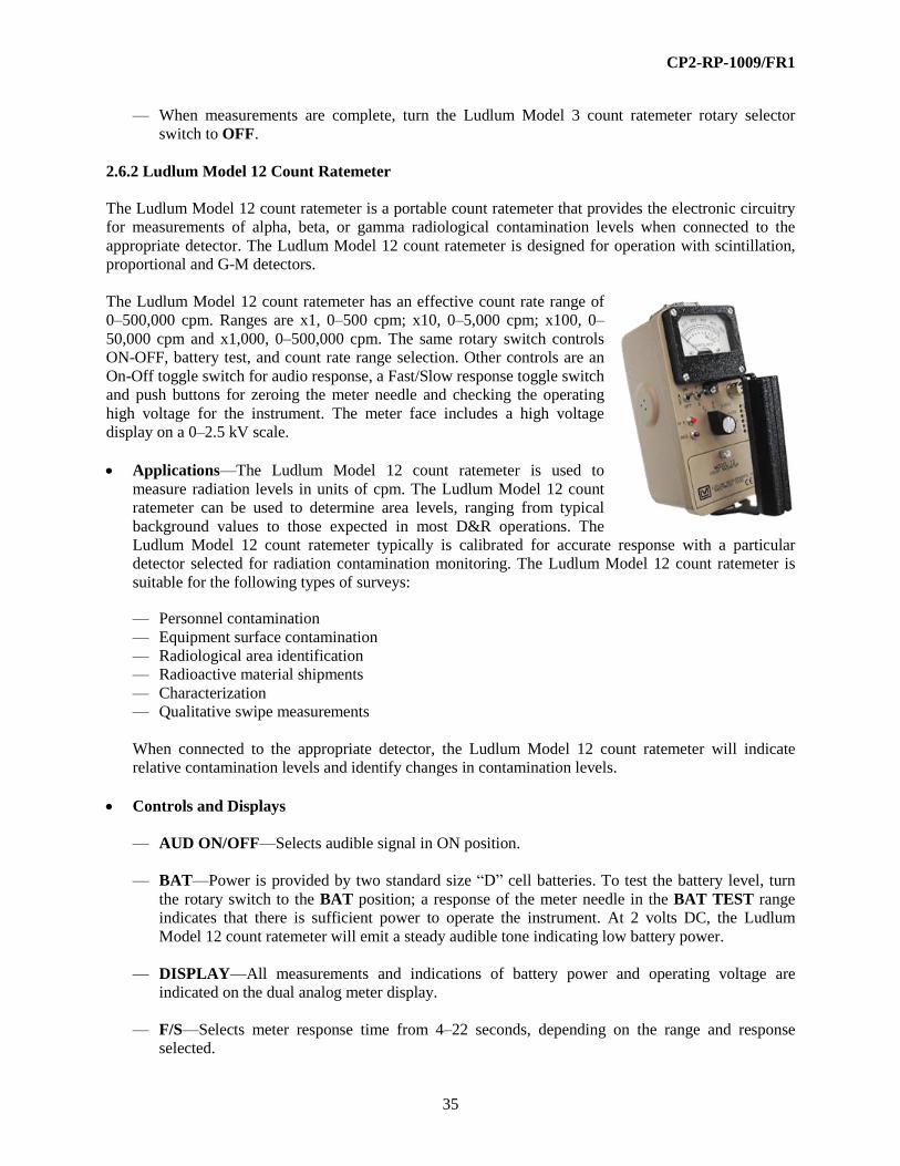
CP2-RP-1009/FR1
35
— When measurements are complete, turn the Ludlum Model 3 count ratemeter rotary selector
switch to OFF.
2.6.2 Ludlum Model 12 Count Ratemeter
The Ludlum Model 12 count ratemeter is a portable count ratemeter that provides the electronic circuitry
for measurements of alpha, beta, or gamma radiological contamination levels when connected to the
appropriate detector. The Ludlum Model 12 count ratemeter is designed for operation with scintillation,
proportional and G-M detectors.
The Ludlum Model 12 count ratemeter has an effective count rate range of
0–500,000 cpm. Ranges are x1, 0–500 cpm; x10, 0–5,000 cpm; x100, 0–
50,000 cpm and x1,000, 0–500,000 cpm. The same rotary switch controls
ON-OFF, battery test, and count rate range selection. Other controls are an
On-Off toggle switch for audio response, a Fast/Slow response toggle switch
and push buttons for zeroing the meter needle and checking the operating
high voltage for the instrument. The meter face includes a high voltage
display on a 0–2.5 kV scale.
Applications—The Ludlum Model 12 count ratemeter is used to
measure radiation levels in units of cpm. The Ludlum Model 12 count
ratemeter can be used to determine area levels, ranging from typical
background values to those expected in most D&R operations. The
Ludlum Model 12 count ratemeter typically is calibrated for accurate response with a particular
detector selected for radiation contamination monitoring. The Ludlum Model 12 count ratemeter is
suitable for the following types of surveys:
— Personnel contamination
— Equipment surface contamination
— Radiological area identification
— Radioactive material shipments
— Characterization
— Qualitative swipe measurements
When connected to the appropriate detector, the Ludlum Model 12 count ratemeter will indicate
relative contamination levels and identify changes in contamination levels.
Controls and Displays
— AUD ON/OFF—Selects audible signal in ON position.
— BAT—Power is provided by two standard size “D” cell batteries. To test the battery level, turn
the rotary switch to the BAT position; a response of the meter needle in the BAT TEST range
indicates that there is sufficient power to operate the instrument. At 2 volts DC, the Ludlum
Model 12 count ratemeter will emit a steady audible tone indicating low battery power.
— DISPLAY—All measurements and indications of battery power and operating voltage are
indicated on the dual analog meter display.
— F/S—Selects meter response time from 4–22 seconds, depending on the range and response
selected.

CP2-RP-1009/FR1
36
— HV—To obtain an indication of instrument operating voltage, depress this push button.
— LED—The LED provides visual indication of an alarm condition.
— RES—To zero the needle on the meter, depress the push button; this will drive the needle to the
zero mark on the display.
Additional Features and Auxiliary Equipment—An array of meter face displays are available with
single or multiple scales for measurements of exposure rate and/or cpm. The Ludlum Model 12 count
ratemeter can be equipped with an optional LED scaler display and range switch.
Compatible Detectors—The Ludlum Model 12 count ratemeter is compatible with these detectors or
their equivalents:
Ludlum Model 43-5 Alpha Scintillator
Ludlum Model 43-89 Alpha Scintillator
Ludlum Model 43-65 Alpha Scintillator
Ludlum Model 44-7 G-M
Ludlum Model 44-9
Ludlum Model 44-9-18
G-M
G-M
Ludlum Model 44-40 G-M
Ludlum Model 44-10 Gamma Scintillator
Ludlum Model 44-110 Gas Proportional
Ludlum Model 43-68 Gas Proportional
Ludlum Model 44-116 Beta Scintillator
Limitations and Precautions
— The Ludlum Model 12 count ratemeter has no overload protection if a detector reaches saturation.
— Battery seal failure can occur if the Ludlum Model 12 count ratemeter is exposed to temperatures
above 100°F.
— This instrument may be equipped with a scaler option that only displays to a maximum of 19,999
counts.
Operation
— Determine the type(s) of contamination to be surveyed. Ensure the detector connected to the
instrument is suitable for the type of contamination.
— Confirm that the Ludlum Model 12 count ratemeter has a valid and legible calibration label; if
not, remove from service and do not use until the condition is corrected.
— Determine the radiation energy range of interest. Historical, job process, and other work
documents should provide information regarding radionuclides and types of contamination
expected. This information is available from the RCT supervisor and typically is provided on the
RWP for the survey(s) to be performed. This will assist in the proper selection of instrumentation.
Ensure that daily instrument performance tests have been satisfactorily completed (all readings

CP2-RP-1009/FR1
37
are within the defined acceptable range) and documented on a daily test sheet or perform those
tests in accordance with established procedure.
— Turn the Ludlum Model 12 count ratemeter rotary switch to bat. Ensure that the needle response
is within the “bat TEST” range on the meter; if not, remove from service and do not use until the
condition is corrected.
— Turn the rotary switch to the x1,000 scale.
— Turn the AUD ON/OFF toggle switch to “ON.”
— Select the S position on the F/S toggle switch for slow response.
— Depress the RES push button; ensure that the meter display reads zero; if not, remove from
service and do not use until the condition is corrected.
— Hold the detector away from your body and in the contamination field of interest, with the scale
switch to highest scale, allow several seconds (approximately 15–20 seconds, depending on the
scale), for response. Continue to select lower scales until the meter indication is as high as
achievable, without being beyond the upper meter scale limit.
— After waiting for the meter reading to stabilize (approximately 15–22 seconds, depending on the
scale), note the indicated value on the meter and multiply by the selected scale to determine the
cpm. The ideal meter response range is typically 70–90% of the maximum possible meter
deflection.
— If the meter is equipped with a scaler option that only displays to 19,999 counts then set the
instrument to a time of 0.1 and multiply times 10 to indicate a 1 minute count total. Do not try to
count how many times the scaler turns over. Remember the analog scale may be used instead of
the scaler also.
— When measurements are complete, turn the Ludlum Model 12 count ratemeter rotary selector
switch to OFF.
2.6.3 Ludlum Model 177 Count Ratemeter
The Ludlum Model 177 count ratemeter is a portable
count ratemeter, with an alarm that provides the
electronic circuitry for measurements of alpha, beta, or
gamma, radiological contamination levels when
connected to the appropriate detector.
The Ludlum Model 177 count ratemeter is designed for
operation with scintillation, proportional, and G-M
detectors.
The Ludlum Model 177 count ratemeter has an effective
count range of 0–500,000 cpm. A rotary switch allows
selection of count range. Ranges are x1, 0–500 cpm;
x10, 0–5,000 cpm; x100, 0–50,000 cpm and x1,000, 0–500,000 cpm. A slide switch controls power to the
instrument (ON-OFF). Push buttons are provided for battery test, high voltage indication, meter zeroing

CP2-RP-1009/FR1
38
and alarm set point check. Other controls are an ON-OFF toggle switch for Fast/Slow response and rotary
knobs for audio volume and alarm set point adjustment. The meter face includes a high voltage display on
a 0–2.5 kV scale. A small red LED is illuminated when the Ludlum Model 177 Count is turned on. A red
ALARM light is illuminated when the alarm set point is exceeded.
Applications—The Ludlum Model 177 count ratemeter is used to measure radiological
contamination levels in units of cpm. It can be used to determine area radiation levels, ranging from
typical background values to those expected in most D&R operations. The Ludlum Model 177 count
ratemeter typically is calibrated for accurate response with a particular detector selected for radiation
contamination monitoring. The Ludlum Model 177 count ratemeter is suitable for the following types
of surveys:
— Personnel contamination
— Equipment surface contamination
— Radiological area identification
— Radioactive material shipments
— Characterization
— Qualitative swipe measurements
When connected to the appropriate detector, this instrument will indicate relative contamination
levels and identify changes in contamination levels.
Controls and Displays
— Alarm Set—To adjust the alarm set point, rotate the friction lock counter clockwise, and turn the
knob. Rotate the friction lock clockwise once the alarm set point has been established.
— Alarm—To test the alarm, depress this push button.
— Bat—Power is provided by either 120-volt line power or an internal 6-volt sealed lead-acid
battery. To test the battery level, depress the BAT push button; a response of the meter needle in
the BAT TEST range indicates that there is sufficient power to operate the instrument. The
battery is continuously charged when the Ludlum Model 177 count ratemeter is connected to line
power and the ON/OFF slide switch is in the ON position.
— Display—All measurements and indications of battery power
and operating voltage are indicated on the dual analog meter
display.
— F/S—To select Fast or Slow instrument response, move this
toggle switch. The toggle switch selects meter response time
from 4-22 seconds, depending on the range and response
selected.
— HV—To obtain an indication of instrument operating voltage, depress this push button.
— LED—The LED provides visual indication of an alarm condition.
— On/Off—To turn the Ludlum Model 177 count ratemeter’s power on, slide the switch to the ON
position.

CP2-RP-1009/FR1
39
— Reset—To zero the needle on the meter, depress the push button; this will drive the needle to the
zero mark on the display.
— Volume—To adjust the audio signal, turn this knob.
Additional Features and Auxiliary Equipment—The Ludlum Model 177 count ratemeter has a
9-pin series D connector mounted on the back panel for connection to various electronic support
items, e.g., a data recorder.
Compatible Detectors—The Ludlum Model 177 count ratemeter is compatible with these detectors
or their equivalents:
Ludlum Model 43-5 Alpha Scintillator
Ludlum Model 43-89 Alpha Scintillator
Ludlum Model 43-65 Alpha Scintillator
Ludlum Model 44-7 G-M
Ludlum Model 44-9 G-M
Ludlum Model 44-40 G-M
Ludlum Model 44-10 Gamma Scintillator
Ludlum Model 44-110 Gas Proportional
Ludlum Model 44-116 Beta Scintillator
Limitations and Precautions
— The Ludlum Model 177 count ratemeter only should be used where sufficient lighting allows the
user to see the meter and other displays.
— The Ludlum Model 177 count ratemeter has no overload protection if a detector reaches
saturation.
— Do not use the Ludlum Model 177 count ratemeter in wet weather conditions when it is being
supplied with line power.
Operation
— Determine the type(s) of contamination to be surveyed. Ensure the detector connected to the
instrument is suitable for the type of contamination.
— Confirm that the Ludlum Model 177 count ratemeter has current and legible calibration label; if
not, remove from service and do not use until condition is corrected.
— Determine the radiation energy range of interest. Historical, job process, and other work
documents should provide information regarding radionuclides and types of contamination
expected. This information is available from the RCT supervisor and typically is provided on the
RWP for the survey(s) to be performed. This will assist in the proper selection of instrumentation.
— Ensure that daily instrument performance tests have been satisfactorily completed (all readings
are within the defined acceptable range) and documented on the daily test sheet or perform those
tests in accordance with established procedure.

CP2-RP-1009/FR1
40
— Turn the Ludlum Model 177 count ratemeter rotary switch to BAT. Ensure that the needle
response is within the “BAT TEST” range on the meter; if not, remove from service and do not
use until the condition is corrected.
— Turn the rotary switch to the x 1,000 scale.
— Turn the AUD ON/OFF toggle switch to “ON.”
— Select the S position on the F/S toggle switch for slow response.
— Depress the RES push button; ensure that the meter display reads zero; if not, remove from
service and do not use until the condition is corrected.
— Holding the Ludlum Model 177 count ratemeter away from your body and in the contamination
field of interest, with the scale switch to highest scale, allowing several seconds (approximately
15-20 seconds depending on scale) for response. Continue to select lower scales until the meter
indication is as high as achievable, without being beyond the upper meter scale limit. The ideal
meter response range is typically 70–90% of the maximum possible meter deflection.
— After waiting for the meter reading to stabilize (approximately 15–22 seconds, depending on the
scale), note the indicated value on the meter and multiply by the selected scale to determine the
cpm.
— When measurements are complete, turn the Ludlum Model 177 count ratemeter rotary selector
switch to OFF.
2.6.4 Ludlum Model 177-45 Count Ratemeter
The Ludlum Model 177-45 count ratemeter is a
portable count ratemeter, with an alarm, which
provides the electronic circuitry for measurements of
alpha, beta, or gamma radiation levels when
connected to the appropriate detector. The Ludlum
Model 177-45 count ratemeter is designed for
operation with scintillation, proportional, and G-M
detectors.
The Ludlum Model 177-45 count ratemeter has an
effective count rate range of 0–500,000 cpm. A
rotary switch allows selection of count range. Ranges
are x1, 0–500 cpm; x10, 0–5,000 cpm; x100, 0–50,000 cpm and x1,000, 0–500,000 cpm. A slide switch
controls power to the instrument (ON-OFF). Push buttons are provided for battery test, high voltage
indication, and meter zeroing. The high voltage push button is located on the back panel of the Ludlum
Model 177-45 count ratemeter. Alarm set point adjustment is made utilizing an 11-position rotary switch
located on the back panel of the instrument. Other controls are the ON-OFF toggle switch, for
FAST/SLOW response, and a rotary knob for audio volume control. The meter face includes a high
voltage display on a 0-2.5 kV scale. A small red LED is illuminated when the instrument is turned on. A
red ALARM light is illuminated when the alarm set point is exceeded. The Ludlum Model 177-45 count
ratemeter also is equipped with an on-off background subtraction slide switch located on the back panel
of the instrument.

CP2-RP-1009/FR1
41
Applications—The Ludlum Model 177-45 count ratemeter is used to measure radiation levels in
units of cpm. It can be used to determine area radiation levels, ranging from typical background
values to those expected in most D&R operations. The Ludlum Model 177-45 count ratemeter
typically is calibrated for accurate response with a particular detector selected for radiological
contamination monitoring.
The Ludlum Model 177-45 count ratemeter is suitable for the following types of surveys:
— Personnel contamination
— Equipment surface contamination
— Radiological area identification
— Radioactive material shipments
— Characterization
— Qualitative swipe measurements
When connected to the appropriate detector, the Ludlum Model 177-45 count ratemeter will indicate
relative contamination levels and identify changes in contamination levels.
Controls and Displays
— Alarm Set Percent—To adjust the alarm set point as a percentage of the meter scale, select the
percentage by turning the rotary switch to the 10, 20, 30, 40, 50, 60, 70, 80, 90, or 100 percent
position. If the alarm function is not needed, turn the rotary switch to the OFF position.
— Alarm—To test the alarm, depress this push button. Depress the RESET push button to clear the
alarm.
— Bat—Power is provided by either 120-volt line power or an internal 6-volt sealed lead-acid
battery. To test the battery level, depress the bat push button; a response of the meter needle in
the bat TEST range indicates that there is sufficient power to operate the instrument. The battery
is continuously charged when the Ludlum Model 177-45 count ratemeter is connected to line
power and the ON/OFF slide switch is in the ON position.
— DISPLAY—All measurements and indications of battery power and operating voltage are
indicated on the dual analog meter display.
— F/S—To select Fast or Slow instrument response, move this toggle switch. The toggle switch
selects meter response time from 4-22 seconds, depending on the range and response selected.
— HV—To obtain an indication of instrument operating voltage, depress this push button, which is
located on the instrument back panel.
— LED—The LED provides visual indication of an alarm condition.
— On/Subtract/Off—To activate the preset background meter needle set point; slide the switch to
the ON position.
— On/Off—To turn the Ludlum Model 177-45 count ratemeter power on, slide the switch to the
ON position.
— Range—To select the cpm range of the instrument display, turn this rotary switch to x1, x10,
x100, or x1K.

CP2-RP-1009/FR1
42
— Reset—To zero the needle on the meter, depress the push button; this will drive the needle to the
zero mark on the display.
— Volume—To adjust the audio signal, turn this knob.
Additional Features and Auxiliary Equipment
— The Ludlum Model 177-45 count ratemeter is equipped with a fast charge jack plug located on
the rear panel. An external battery charger is available for supplying a fast charge to the internal
lead-acid battery.
— The Ludlum Model 177-45 count ratemeter is equipped with a jack plug located on the rear panel
for a data recorder.
— The Ludlum Model 177-45 count ratemeter is equipped with an MHV connector to allow an
output connection to a scaler or other measurement device.
Compatible Detectors—The Ludlum Model 177-45 count ratemeter is compatible with these
detectors or their equivalents:
Ludlum Model 44-7 G-M
Ludlum Model 44-9 G-M
Ludlum Model 44-40 G-M
Ludlum Model 44-10 Gamma Scintillator
Ludlum Model 44-110 Gas Proportional
Ludlum Model 44-116 Beta Scintillator
Limitations and Precautions
— The Ludlum Model 177-45 count ratemeter only should be used where sufficient lighting allows
the user to see the meter and other displays.
— The Ludlum Model 177-45 count ratemeter has no overload protection as a detector reaches
saturation.
— Do not use the Ludlum Model 177-45 count ratemeter in wet weather conditions when it is being
supplied with line power.
Operation
— Determine the type(s) of contamination to be surveyed. Ensure the detector connected to the
instrument is suitable for the type of contamination.
— Confirm that the Ludlum Model 177-45 count ratemeter has a current and legible calibration
label; if not, remove from service and do not use until the condition is corrected.
— Determine the radiological contamination levels of interest. Historical, job process, and other
work documents should provide information regarding radionuclides and types of contamination
expected. This information is available from the RCT supervisor and typically is provided on the
RWP for the survey(s) to be performed. This will assist in the proper selection of instrumentation.

CP2-RP-1009/FR1
43
— Ensure that daily instrument performance tests have been satisfactorily completed (all readings
are within the defined acceptable range) and documented on a daily test sheet or perform those
tests in accordance with established procedure.
— Ensure that the ON/SUBTRACT/OFF slide switch is in the OFF position, unless job
requirements indicate otherwise.
— Ensure that the ALARM SET PERCENT switch, located on the back panel, is in the OFF
position, unless job requirements indicate otherwise.
— Depress the bat push button. Ensure that the needle response is within the “bat TEST” range on
the meter; if not, remove from service and do not use until condition is corrected.
— Turn the RANGE rotary switch to the x1,000 mark.
— Turn the AUD ON/OFF toggle switch to “ON.”
— Select the S position on the F/S toggle switch for slow response.
— Depress the RES push button; ensure that the meter display reads zero; if not, remove from
service and do not use until the condition is corrected.
— Holding the Ludlum Model 177-45 count ratemeter away from your body and in the
contamination field of interest, with the scale switch to highest scale, allowing several seconds
(approximately 15–20 seconds depending on scale) for response. Continue to select lower scales
until the meter indication is as high as achievable, without being beyond the upper meter scale
limit. The ideal meter response range is typically 70–90% of the maximum possible meter
deflection.
— After waiting for the meter reading to stabilize (approximately 15–22 seconds, depending on the
scale), note the indicated value on the meter and multiply by the selected scale to determine the
cpm.
— When measurements are complete, turn the Ludlum Model 177-45 count ratemeter slide switch to
OFF.
2.6.5 Ludlum Model 2221 Count Ratemeter/Scaler
The Ludlum Model 2221 count ratemeter/scaler is a portable combination count ratemeter and scaler that
provides the electronic circuitry for measurements of alpha, beta, or gamma contamination levels when
connected to the appropriate detector.
It is designed for operation with scintillation, proportional, and G-M detectors. The Ludlum Model 2221
count ratemeter/scaler also may be used for counting smears and can be calibrated for operation as a
single channel analyzer (SCA).

CP2-RP-1009/FR1
44
The Ludlum Model 2221 count ratemeter/scaler has an effective
count rate range of 0-500,000 cpm. A rotary switch allows
selection of count range. Ranges are x1, 0–500 cpm; x10, 0–5,000
cpm; x100, 0–50,000 cpm and x1,000, 0–500,000 cpm. A
logarithmic range scale also may be selected. When this
instrument is operated as a scaler, the LCD digital display range is
0-999999 counts.
A toggle switch controls power to the instrument (ON-OFF). Push
buttons located on the left side of the face panel are provided for
battery test, high voltage indication, energy threshold set point,
and energy window set point. Push buttons located on the right
side of the face panel are provided for meter zeroing, scaler count
“Start” and scaler count “Hold.” Scaler count time adjustment is
made utilizing an 8-position rotary switch located on the right side
of the face panel of the instrument. Other controls are Lamp On-
Off, for LCD display illumination, Fast/Slow instrument response,
and selection of digital display in ratemeter or scaler mode. A
three-position toggle switch is provided for selection of number of clicks per event and a rotary knob for
audio volume control. A plug jack is provided for earphones. A rotary switch is provided for selection of
energy window “In” or energy window “Out.” The meter face includes both linear and logarithmic
scales.
Applications—The Ludlum Model 2221 count ratemeter/scaler is used to measure radiation levels in
units of cpm. It can be used to determine area radiation levels, ranging from typical background
values to those expected in most D&R operations.
The Ludlum 2221 count ratemeter/scaler typically is calibrated for accurate response with a particular
detector selected for radiological contamination monitoring. The Ludlum Model 2221 count
ratemeter/scaler is suitable for the following types of surveys:
— Personnel contamination
— Equipment surface contamination
— Radiological area identification
— Radioactive material shipments
— Characterization
— Qualitative swipe measurements
When connected to the appropriate detector, the Ludlum Model 2221 count ratemeter/scaler will
indicate relative contamination levels and identify changes in contamination level.
Controls and Displays
— Audio Divide—To select a reduction in the number of audible clicks, move this toggle switch to
a divisor of 100, 10, or 1.
— Bat—Power is provided by four standard D-size cell batteries. To test the battery level, depress
the BAT push button; a reading on the LCD display of 4.8 or greater indicates there is sufficient
power to operate the Ludlum Model 2221 count ratemeter/scaler.
— Count—To begin a scaler-counting period, depress this push button.

CP2-RP-1009/FR1
45
— Display—All measurements and indication of battery power, threshold set point, window set
point, and operating voltage are indicated on the LCD display. All measurements are indicated on
the dual analog display.
— Hold—To temporarily suspend or freeze the collection of scaler count, depress this push button.
To continue collection of counts, depress this push button.
— HV—To obtain an indication of instrument operating
voltage, depress this push button. The voltage is indicated
on the LCD display.
— Minutes—To select the count time for scaler use, turn
this rotary switch to 10, 5, 2, 1, 0.5, 0.2, or 0.1 count time
in minutes, or CONT. for continuous collection of counts.
— On-Off—To turn the instrument power on, turn the
switch to the ON position.
— RANGE—To select the cpm range of the instrument
analog display, turn this rotary switch to x1, x10, x100, or
x1K. Turn the rotary switch to the LOG position to use
the logarithmic scale on the analog display.
— Resp F/S—To select Fast or Slow instrument response,
move this toggle switch. The toggle switch selects meter
response time from 4–22 seconds, depending on the range
and response selected.
— Scaler/Dig. Rate—To select indication of counter
contents on the analog display, move this toggle switch to
SCALER. To select indication of count rate on the LCD
display, move this toggle switch to DIG. RATE.
— Note: The scaler and ratemeter are active even when not
selected; this allows simultaneous use for count collection
and obtaining an instantaneous indication of count rate.
— THR—To obtain an indication of the preset energy threshold, depress this push button. The
threshold will be indicated on the LCD display.
— Volume—To adjust the audio signal, turn this knob.
— WIN—To obtain an indication of the preset energy window, depress this push button. The
window will be indicated on the LCD display.
— Zero—To zero the needle on the meter, depress the push button; this will drive the needle to the
zero mark on the analog display.
Additional Features and Auxiliary Equipment—A headset may be used with the Ludlum
Model 2221 count ratemeter/scaler for audio reception.

CP2-RP-1009/FR1
46
Compatible Detectors—The Ludlum Model 2221 count ratemeter/scaler is compatible with these
detectors or their equivalents:
Ludlum Model 43-5 Alpha Scintillator
Ludlum Model 43-89 Alpha Scintillator
Ludlum Model 43-65 Alpha Scintillator
Ludlum Model 44-7 G-M
Ludlum Model 44-9 G-M
Ludlum Model 44-40
Ludlum Model 44-3
G-M
Gamma Scintillator
Ludlum Model 44-10 Gamma Scintillator
Ludlum Model 44-17 Gamma Scintillator
Ludlum Model 44-110 Gas Proportional
Ludlum Model 44-116 Beta Scintillator
Ludlum Model 43-68 Gas Proportional
Limitations and Precautions
— The Ludlum 2221 count ratemeter/scaler typically is used for field measurements in a gross count
rate RATEMETER or count collection SCALER mode. Unless job requirements indicate
otherwise, operate the Ludlum Model 2221 count ratemeter/scaler with the WIN rotary switch in
the OUT position.
— The Ludlum Model 2221 count ratemeter/scaler has no illumination for the analog meter display
and should not be used in poorly lit environments.
Operation
— Determine the type(s) of contamination to be surveyed. Ensure the detector connected to the
instrument is suitable for the type of contamination.
— Confirm that the Ludlum Model 2221 count ratemeter/scaler has a current and legible calibration
label; if not, remove from service and do not use until condition is corrected.
— Determine the radiological contamination levels of interest. Historical, job process, and other
work documents should provide information regarding radionuclides and types of contamination
expected. This information is available from the RCT supervisor and typically is provided on the
RWP for the survey(s) to be performed. This will assist in the proper selection of instrumentation.
— Ensure that daily instrument performance tests have been satisfactorily completed (all readings
are within the defined acceptable range) and documented on a daily test sheet or perform those
tests in accordance with established procedure.
— Ensure that the WIN rotary switch is in the OUT position, unless job requirements indicate
otherwise.
— Move the ON-OFF toggle switch to ON. A random number will be indicated on the LCD
display, followed by 8..8:8:8:8:8, then the number of the instrument program version will be
indicated on the LCD display (e.g., 26 10 10).

CP2-RP-1009/FR1
47
— Depress the BAT push button. Ensure that the voltage indicated on the LCD display is 4.8 or
greater; if not, remove from service and do not use until the condition is corrected.
Ratemeter Operation:
— Turn the RATEMETER rotary switch to the x 1K mark.
— Turn the AUDIO DIVIDE toggle switch to “1.” Turn the VOL knob clockwise until clicks are
audible.
— Select the S position on the RESP F/S toggle switch for slow response.
— Depress the ZERO push button; ensure that the analog and LCD meter displays read zero; if not,
remove from service and do not use until condition is corrected.
— Move the SCALER – DIG. RATE toggle switch to the DIG.RATE position.
— Holding the Ludlum Model 2221 count ratemeter/scaler away from your body and in the
contamination field of interest, with the scale switch to highest scale, allowing several seconds
(approximately 15-20 seconds depending on scale) for response.
— Continue to select lower scales until the analog meter indication is as high as achievable, without
being beyond the upper meter scale limit. The ideal meter response is typically 70–90% of the
maximum possible meter deflection.
— After waiting for the meter reading to stabilize (approximately 15-22 seconds, depending on the
scale), note the indicated count rate value on the LCD meter display.
— When measurements are complete, turn the instrument rotary selector switch to OFF.
Scaler Operation:
— Turn the AUDIO DIVIDE toggle switch to “1.” Turn the VOL knob clockwise until clicks are
audible.
— Depress the ZERO push button; ensure that the analog and LCD meter displays read zero; if not,
remove from service and do not use until the condition is corrected.
— Move the SCALER-DIG.RATE toggle switch to the SCALER position.
— Turn the MINUTES rotary switch to the select count collection time, or select. CONT. for a
continuous count.
— Holding or placing the Ludlum Model 2221 count ratemeter/scaler away from your body and in
the contamination field of interest, depress the COUNT push button.
— When the count has been completed, note the indicated value on the LCD display and count time
selected on the MINUTES rotary switch.
— When measurements are complete, move the Ludlum Model 2221 Count Ratemeter/Scaler’s
power toggle switch to OFF.
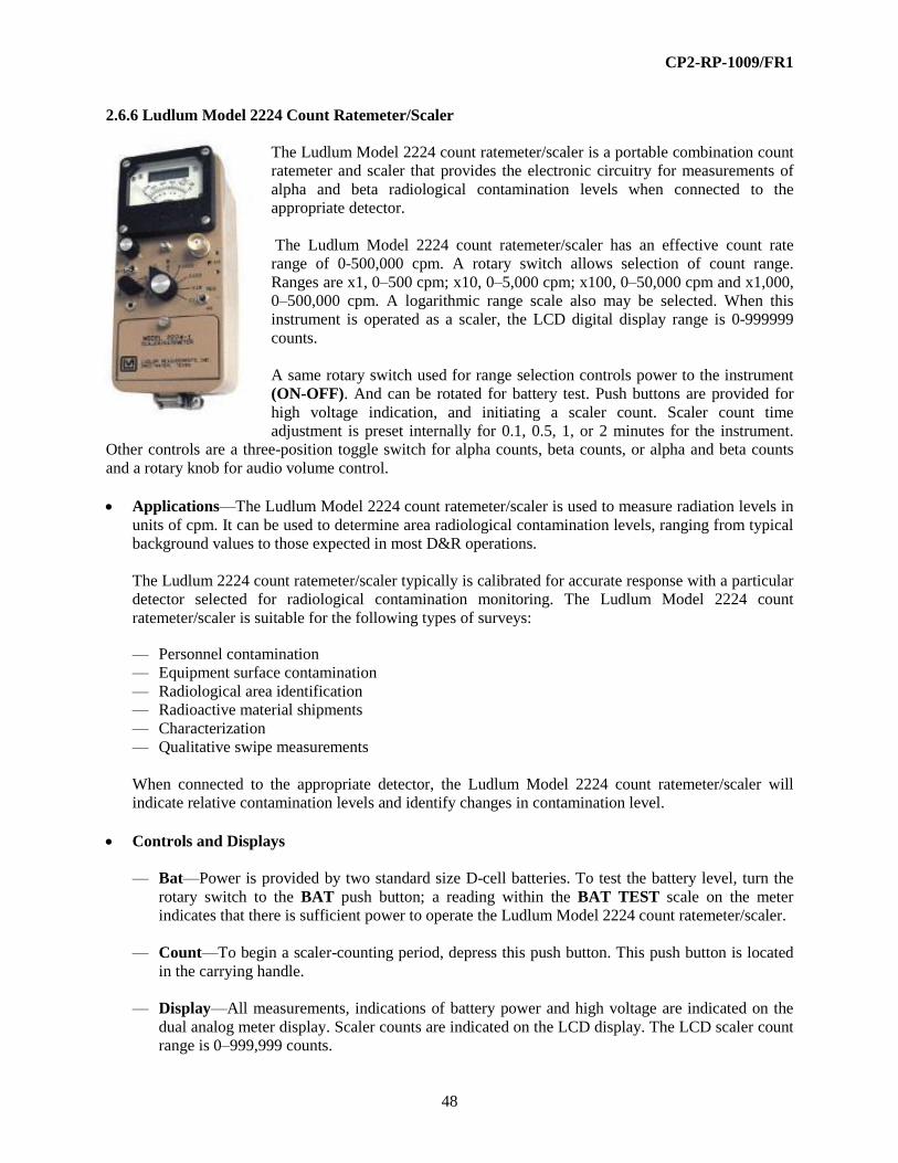
CP2-RP-1009/FR1
48
2.6.6 Ludlum Model 2224 Count Ratemeter/Scaler
The Ludlum Model 2224 count ratemeter/scaler is a portable combination count
ratemeter and scaler that provides the electronic circuitry for measurements of
alpha and beta radiological contamination levels when connected to the
appropriate detector.
The Ludlum Model 2224 count ratemeter/scaler has an effective count rate
range of 0-500,000 cpm. A rotary switch allows selection of count range.
Ranges are x1, 0–500 cpm; x10, 0–5,000 cpm; x100, 0–50,000 cpm and x1,000,
0–500,000 cpm. A logarithmic range scale also may be selected. When this
instrument is operated as a scaler, the LCD digital display range is 0-999999
counts.
A same rotary switch used for range selection controls power to the instrument
(ON-OFF). And can be rotated for battery test. Push buttons are provided for
high voltage indication, and initiating a scaler count. Scaler count time
adjustment is preset internally for 0.1, 0.5, 1, or 2 minutes for the instrument.
Other controls are a three-position toggle switch for alpha counts, beta counts, or alpha and beta counts
and a rotary knob for audio volume control.
Applications—The Ludlum Model 2224 count ratemeter/scaler is used to measure radiation levels in
units of cpm. It can be used to determine area radiological contamination levels, ranging from typical
background values to those expected in most D&R operations.
The Ludlum 2224 count ratemeter/scaler typically is calibrated for accurate response with a particular
detector selected for radiological contamination monitoring. The Ludlum Model 2224 count
ratemeter/scaler is suitable for the following types of surveys:
— Personnel contamination
— Equipment surface contamination
— Radiological area identification
— Radioactive material shipments
— Characterization
— Qualitative swipe measurements
When connected to the appropriate detector, the Ludlum Model 2224 count ratemeter/scaler will
indicate relative contamination levels and identify changes in contamination level.
Controls and Displays
— Bat—Power is provided by two standard size D-cell batteries. To test the battery level, turn the
rotary switch to the BAT push button; a reading within the BAT TEST scale on the meter
indicates that there is sufficient power to operate the Ludlum Model 2224 count ratemeter/scaler.
— Count—To begin a scaler-counting period, depress this push button. This push button is located
in the carrying handle.
— Display—All measurements, indications of battery power and high voltage are indicated on the
dual analog meter display. Scaler counts are indicated on the LCD display. The LCD scaler count
range is 0–999,999 counts.

CP2-RP-1009/FR1
49
— HV—To obtain an indication of instrument operating voltage, depress this push button. The
voltage is indicated on the analog meter display in units of kV.
— OL—This red lamp, located on the face of the meter display will illuminate when the detector in
use reaches saturation or when the detector in use is exposed to a radiation field above the
capability of this instrument.
— On-Off—To turn the Ludlum Model 2224 count ratemeter/scaler power on, turn the rotary switch
from the OFF position.
— Range—To select the cpm range of the instrument analog display, turn this rotary switch to x1,
x10, x100, or x1K.
— Volume—To adjust the audio signal, turn this knob.
Additional Features and Auxiliary Equipment—There are no additional features or auxiliary
equipment for the Ludlum Model 2224 count ratemeter/scaler.
Compatible Detectors—The Ludlum Model 2224 count ratemeter/scaler is compatible with these
detectors or their equivalents:
Ludlum Model 43-5 Alpha Scintillator
Ludlum Model 43-89 Alpha Scintillator
Ludlum Model 43-65 Alpha Scintillator
Ludlum Model 43-10-1 Alpha/Beta Scintillator
Ludlum Model 44-9 G-M
Ludlum Model 43-68 Gas Proportional
Operation
— Determine the type(s) of contamination to be surveyed. Ensure the detector connected to the
instrument is suitable for the type of contamination.
— Confirm that the Ludlum Model 2224 count ratemeter/scaler has a current and legible calibration
label; if not, remove from service and do not use until the condition is corrected.
— Determine the radiological contamination levels of interest. Historical, job process, and other
work documents should provide information regarding radionuclides and types of contamination
expected. This information is available from the RCT supervisor and typically is provided on the
RWP for the survey(s) to be performed. This will assist in the proper selection of instrumentation.
— Ensure that daily instrument performance tests have been satisfactorily completed (all readings
are within the defined acceptable range) and documented on a daily test sheet or perform those
tests in accordance with established procedure.
— Turn the rotary switch from the OFF position to the ON position. Ensure that the voltage
indicated on the analog meter display is within the BAT OK scale; if not, remove from service
and do not use until the condition is corrected. Turn the VOL knob clockwise until clicks are
audible.
CP2-RP-1009/FR1
50
— Depress the RES push button; ensure that the analog meter display reads zero; if not, remove
from service and do not use until condition is corrected.
— If the OL lamp illuminates, remove from service and do not use until the condition is corrected.
Ratemeter Operation:
— Depress the HV push button. Assure that the voltage indicated on the analog meter display is
correct for the detector in use; if not, remove from service and do not use until the condition is
corrected.
— Move the α/α+β/β toggle switch to the α position for measurement of alpha radiation, the β
position for measurement of beta radiation, or the α+β position for making measurements of both
alpha and beta radiation.
— Holding the Ludlum Model 2224 count ratemeter/scaler away from your body and in the
contamination field of interest, turn the rotary scale switch to the highest scale, allowing several
seconds (approximately 15–20 seconds depending on scale) for response. Continue to select
lower scales until the analog meter indication is as high as achievable, without being beyond the
upper meter scale limit. The ideal meter response range is typically 70–90% of the maximum
possible meter deflection.
— After waiting for the meter reading to stabilize (approximately 15–22 seconds, depending on the
scale), note the indicated count rate value on the analog meter display and record this value
multiplied by the range selected.
— If the OL lamp illuminates, discontinue taking measurements, remove the Ludlum Model 2224
count ratemeter/scaler from service and do not use until the condition is corrected.
— When measurements are complete, turn the instrument rotary selector switch to OFF.
Scaler Operation:
— Depress the HV push button. Ensure that the voltage indicated on the analog meter display is
correct for the detector in use; if not, remove from service and do not use until the condition is
corrected.
— Turn the VOL knob clockwise until clicks are audible.
— Depress the ZERO push button; ensure that the analog and the LCD meter displays read zero; if
not, remove from service and do not use until the condition is corrected.
— Holding or placing the Ludlum Model 2224 count ratemeter/scaler away from your body and in
the contamination field of interest, depress the COUNT push button located in the carrying
handle.
— If the OL lamp illuminates, discontinue taking measurements, remove the Ludlum Model 2224
count ratemeter/scaler from service and do not use until the condition is corrected.
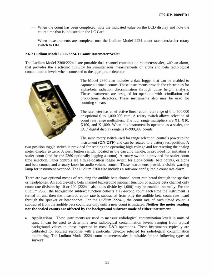
CP2-RP-1009/FR1
51
— When the count has been completed, note the indicated value on the LCD display and note the
count time that is indicated on the LC Card.
— When measurements are complete, turn the Ludlum Model 2224 count ratemeter/scaler rotary
switch to OFF.
2.6.7 Ludlum Model 2360/2224-1 Count Ratemeter/Scaler
The Ludlum Model 2360/2224-1 are portable dual channel combination ratemeter/scaler, with an alarm,
that provides the electronic circuitry for simultaneous measurements of alpha and beta radiological
contamination levels when connected to the appropriate detector.
The Model 2360 also includes a data logger that can be enabled to
capture all timed counts. These instruments provide the electronics for
alpha-beta radiation discrimination through pulse height analysis.
These instruments are designed for operation with scintillation and
proportional detectors. These instruments also may be used for
counting smears.
The ratemeter has an effective linear count rate range of 0 to 500,000
or optional 0 to 1,000,000 cpm. A rotary switch allows selection of
count rate range multipliers. The four range multipliers are X1, X10,
X100, and X1,000. When this instrument is operated as a scaler, the
LCD digital display range is 0–999,999 counts.
The same rotary switch used for range selection, controls power to the
instrument (ON-OFF) and can be rotated to a battery test position. A
two-position toggle switch is provided for reading the operating high voltage and for resetting the analog
meter display to zero. A push button switch, located in the carrying handle, is provided for initiating a
scaler count (and for the 2360 optionally logging a count). A rotary switch is provided for scaler count
time selection. Other controls are a three-position toggle switch for alpha counts, beta counts, or alpha
and beta counts, and a rotary knob for audio volume control. These instruments provide a visible warning
lamp for instrument overload. The Ludlum 2360 also includes a software configurable count rate alarm.
There are two optional means of reducing the audible beta channel count rate heard through the speaker
or headphones. An audible-only, beta channel background subtract function or audible beta channel only
count rate division by 10 or 100 (2224-1 also adds divide by 1,000) may be enabled internally. For the
Ludlum 2360, the background subtract function collects a 12-second count each time the instrument is
turned on and then the measured count rate is subtracted from only the audible beta count rate heard
through the speaker or headphones. For the Ludlum 2224-1, the count rate of each timed count is
subtracted from the audible beta count rate only until a new count is initiated. Neither the meter reading
nor the scaled counts are affected by the background subtract mode of either instrument.
Applications—These instruments are used to measure radiological contamination levels in units of
cpm. It can be used to determine area radiological contamination levels, ranging from typical
background values to those expected in most D&R operations. These instruments typically are
calibrated for accurate response with a particular detector selected for radiological contamination
monitoring. The Ludlum Model 2224 count ratemeter/scaler is suitable for the following types of
surveys:

CP2-RP-1009/FR1
52
— Personnel contamination
— Equipment surface contamination
— Radiological area identification
— Radioactive material shipments
— Characterization
— Qualitative swipe measurements
When connected to the appropriate detector, this instrument will indicate relative contamination
levels and identify changes in contamination levels.
Controls and Displays
— Alarm (2360 Only)—This red lamp, located on the face of the meter display, will illuminate and
the instrument audio signal will be activated when any of the following six preset alarm cpm set
points is exceeded:
— Scaler—alpha, or beta, or alpha + beta
— Ratemeter—alpha, or beta, or alpha + beta
— Bat—To test the battery level, turn the rotary switch to the BAT position; a reading within the
BAT TEST scale on the meter indicates that there is sufficient power to operate the instrument.
— Count—To begin a scaler-counting period, (and log a count if enabled on the 2360) depress this
push button. This push button is located on the end of the carrying handle.
— Display—All measurements, indications of battery power and high voltage are indicated on the
dual analog/digital meter display. Scaler counts are indicated on the LCD display. The LCD
scaler count range is 0-999,999 counts.
— LED—The LED provides visual indication of an alarm condition.
— Min—To select scaler count time, turn this rotary switch to 0.5, 1, 2, 5 (2224-1) or 0.1, 0.5, 1, 2,
5, 10, 60, or PC (2360) for a specific preprogrammed count time.
— Overload—This red lamp, located on the face of the meter display, will illuminate when the
detector saturates usually when the Mylar is punctured resulting in a light leak.
— Range—To select the cpm range of the instrument analog display, turn this rotary switch to x1,
x10, x100, or x1,000.
— Read HV—To obtain an indication of instrument operating voltage, move the toggle switch to
the READ HV position. The voltage is indicated on the analog meter display in units of kV.
— Reset—To zero the needle on the analog meter, move the toggle switch to the RESET position;
this will drive the needle to the zero mark on the display.
— Volume—To adjust the audio signal, turn this knob.
Additional Features and Auxiliary Equipment—(2360 Only) Data Logger—If enabled, the results
of the last 550 data points are logged each time the count button is depressed. The ratemeter, scaler,
CP2-RP-1009/FR1
53
or both may be logged and downloaded via the 9-pin RS-232C port and supplied software. The data
retained consists of the following:
— Sample #
— Date/Time
— Sample measurement (alpha and beta)
— “S” or “R” denoting whether the result is from the scaler or ratemeter
— 10 character location identifier
Consult the Instrumentation Group regarding procedures for downloading logged data.
— Response Time—X1 & X10 = 7 seconds; X100 & X1,000 = 2 seconds
— Power—Two D-cell (Alkaline) batteries provide 250 hours of operation
— Headphone Jack—Inserting plug disables internal speaker
Compatible Detectors—This instrument is compatible with these detectors or their equivalents:
Ludlum Model 43-5 Alpha Scintillator
Ludlum Model 43-89 Alpha/Beta Scintillator
Ludlum Model 43-10-1 Alpha/Beta Scintillator
Operation
— Determine the type(s) of contamination to be surveyed. Ensure the detector connected to the
instrument is suitable for the type of contamination. Historical, job process, and other work
documents should provide information regarding radionuclides and types of contamination
expected.
— This information is available from the RCT supervisor and typically is provided on the RWP for
the survey (s) to be performed. This will assist in the proper selection of instrumentation.
— Confirm that the instrument has a current and legible calibration label; if not, remove from
service and do not use until the condition is corrected.
— Ensure that daily instrument performance tests have been satisfactorily completed (all readings
are within the defined acceptable range) and documented on a daily test sheet or perform those
tests in accordance with established procedure.
— Turn the rotary switch from the OFF position to the BAT position. The internal microprocessor
will flash “88:8:8.8:8.8” for about 2 seconds on the LCD display drive the meter needle to full
scale. (2360 only) The 12-second background count (if the beta subtract mode is enabled) will be
initiated automatically. Ensure that the voltage indicated on the analog meter display is within the
BAT OK scale; if not, remove from service and do not use until the condition is corrected.
— Turn the VOL knob clockwise until clicks are audible. Headphones may be connected to the jack.
— Move the two-position toggle switch to RESET; ensure that the analog meter display read zero;
if not, remove from service and do not use until the condition is corrected.
— If the OVERLOAD lamp illuminates, remove from service and do not use until the condition is
corrected.

CP2-RP-1009/FR1
54
— If the ALARM lamp illuminates, remove from service and do not use until the condition is
corrected.
Ratemeter Operations:
— Move the α/α+β/β toggle switch to the α position for measurement of alpha radiation, the β
position for measurement of beta radiation, or the α+β position for making measurements of both
alpha and beta radiation.
— Select the lowest scale until the analog meter indication is as high as achievable, without being
beyond the upper meter scale limit.
— After waiting for the meter reading to stabilize (approximately 4–15 seconds, depending on the
scale), note the indicated count rate value on the analog meter display and record this value
multiplied by the range selected.
— If the OL lamp illuminates, determine the cause. If the probe’s window is punctured, discontinue
taking measurements, remove the instrument from service and do not use until condition is
corrected.
— If the ALARM lamp illuminates, determine the cause. If the probe’s window is punctured,
discontinue taking measurements, remove the instrument form service and do not use until
condition is corrected.
— When measurements are complete, turn the instrument rotary selector switch to OFF.
Scaler Operation:
— Turn the VOL knob clockwise until clicks are audible. Headphones may be connected to the
phone jack.
— Move the 2-position toggle switch to RESET; ensure that the analog meter display reads zero; if
not, remove from service and do not use until the condition is corrected.
— Holding or placing the detector away from your body and in the contamination field of interest,
depress the COUNT push button located in the carrying handle.
— If the OL or ALARM lamp illuminates, determine the cause. If the probe’s window is punctured,
discontinue taking measurements, remove the instrument from service and do not use until the
condition is corrected.
— Colons, : :, on the LCD display will turn on and remain on until the count period is completed;
note the indicated value on the LCD display, and note the count time that is indicated on the
calibration label when the count is completed.
— When measurements are complete, turn the instrument rotary switch to OFF.

CP2-RP-1009/FR1
55
2.6.8 Bicron Frisk Tech Count Ratemeter
The Bicron Frisk Tech Count Ratemeter is a count ratemeter, with an alarm that provides the electronic
circuitry for measurements of alpha, beta, or gamma, radiation levels when connected to the appropriate
detector. The Bicron Frisk Tech Count Ratemeter is designed for operation with scintillation and G-M
detectors.
The Bicron Frisk Tech Count Ratemeter has an effective
count rate range of 0 to 500,000 counts per minute (cpm).
A 7 -position rotary switch allows selection of count range.
Ranges are these: x 1, 0–500 cpm; x 10, 0–5,000 cpm;
x 100, 0–50,000 cpm; and x 10,000–500,000 cpm. The
same rotary switch allows alarm set point and battery
testing and a position to check operating high voltage. A
thumb switch controls power to the instrument
(POWER-ON). A pushbutton is provided for meter
zeroing.
Rotary knobs are provided for Fast/Slow response, audio volume control, and selecting a pulsed or alarm
audio tone. The analog meter face includes a high voltage display on a 0-2.0 kilo-volts (kV) scale. A
small red LED is illuminated when the instrument is connected to 120 volt AC line power. A red
ALARM LED is illuminated when the alarm set point is exceeded.
Applications—The Bicron Frisk Tech Count Ratemeter is used to measure radiation levels in units of
counts per minute. It can be used to determine area radiation levels, ranging from typical background
values to those expected in most D&R operations. The Bicron Frisk Tech Count Ratemeter is
typically calibrated for accurate response with a particular detector selected for radiation
contamination monitoring. The Bicron Frisk Tech Count Ratemeter is suitable for the following types
of surveys:
— Personnel contamination
— Equipment surface contamination
— Radiological area identification
— Radioactive material shipments
— Characterization
— Qualitative swipe measurements
When connected to the appropriate detector, this instrument will indicate relative contamination
levels and identify changes in contamination levels.
Controls and Displays
— ALARM LED—The LED provides visual indication of an alarm condition.
— ALARM SET—To test the alarm set point in all four ranges, turn the RATEMETER range
rotary switch to this position.
— Bat—Power is provided by either 120-volt AC line power or two internal 6-volt sealed lead-acid
batteries. To test the battery level, tum the RATEMETER range rotary switch to the Bat position.
A response of the meter needle in the “bat. ok” range indicates that there is sufficient power to
operate the Bicron Frisk Tech Count Ratemeter. The battery is continuously charged when the

CP2-RP-1009/FR1
56
instrument is connected to line power. DISPLAY-All measurements and indications of battery
power and operating voltage are indicated on the dual analog meter display.
— HV—To obtain an indication of instrument operating voltage, tum the RATEMETER range
rotary switch to the HV position.
— LED—The LED provides visual indication of an alarm condition.
— METER RESET—To zero the needle on the meter, depress the pushbutton; this will drive the
needle to the zero mark on the display.
— POWER-ON—To turn the instrument power on, Push this thumb switch to the ON (-) position.
— RESPONSE—To select Fast or Slow instrument response, tum this knob. The control knob
selects meter response time from 2–20 seconds.
— SPEAKER—To turn the audio alarm signal on, select either the PULSE IALARM position. The
PULSEI ALARM position provides an audible click for each detector event and an audible full
volume signal tone in place of the PULSE signal when the alarm set point is exceeded. The
ALARM position provides only a full volume audible alarm signal only [i.e., there is no audible
signal unless the alarm set point is exceeded].
— VOLUME—To adjust the audio signal, turn this knob.
Additional Features and Auxiliary Equipment—The Bicron Frisk Tech Count Ratemeter has a
digital scaler option; an LCD is provided in the meter display face and a count time selection switch
is installed in the instrument back panel.
The Bicron Frisk Tech Count Ratemeter provides recorder and scaler output jacks and a plug jack for
headphones on the rear panel.
The Bicron Frisk Tech Count Ratemeter may be equipped with a mR/h meter display face.
Compatible Detectors—The Bicron Frisk Tech Count Ratemeter is compatible with the following
detectors, or their equivalents:
Bicron Model A-50 Alpha Scintillator
Bicron Model PGM G-M
Bicron Model LPGM G-M
Limitations and Precautions—The Bicron Frisk Tech Count Ratemeter should only be used where
sufficient lighting allows the user to see the meter and other displays. The Bicron Frisk Tech Count
Ratemeter has no overload protection if a detector reaches saturation. Do not use the Bicron Frisk
Tech Count Ratemeter in wet weather conditions when it is being supplied with line power.

CP2-RP-1009/FR1
57
Operation
— Determine the type(s) of contamination to be surveyed. Ensure the detector connected to the
instrument is suitable for the type of contamination.
— Confirm that the instrument has a current and legible calibration label; if not, remove from
service and do not use until condition is corrected.
— Determine the radiation energy range of interest. Historical, job-process, and other work
documents should provide information regarding radionuclides and types of contamination
expected. This information is available from the Radiological Control Technician Supervisor and
is typically provided on the Radiation Work Permit for the survey(s) to be performed. This will
assist in the proper selection of instrumentation.
— Ensure that daily instrument performance tests have been satisfactorily completed (all readings
are within the defined acceptable range) and documented on a Daily Test Sheet or perform those
tests in accordance with established procedure.
— Push the POWER-ON thumb switch to the ON position.
— Tum the Bicron Frisk Tech Count Ratemeter's rotary switch to Bat-labeled position.
— Ensure that the needle response is within the “bat ok” range on the meter; if not, remove from
service and do not use until condition is corrected.
— Turn the rotary switch to the HV position. The meter needle should indicate the voltage for the
detector in use.
— Multiply the indicated kV value on the lower scale of the display by 1,000 to obtain the operating
voltage in units of volts; if the correct operating voltage for the detector in use is not indicated on
the display, remove from service and do not use until condition is corrected.
— Tum the rotary switch to the x 1,000 position.
— Tum the SPEAKER rotary switch to “PULSE! ALARM” position.
— Select the Slow position on the RESPONSE control knob for slow response.
— Depress the METER RESET pushbutton; ensure that the meter display reads zero; if not, remove
from service and do not use until condition is corrected.
— Holding the Bicron Frisk Tech Count Ratemeter away from your body and in the contamination
field of interest, with the scale switch to highest scale, (approximately 15-22 seconds, depending
on the scale) for response. Continue to select lower scales until the meter indication is as high as
achievable, without being beyond the upper meter scale limit.
— After waiting for the meter reading to stabilize, note the indicated value on the meter and multiply
by the selected scale to determine the counts per minute.
— When measurements are complete, turn the Bicron Frisk Tech Count Ratemeter's rotary selector
switch to OFF.

CP2-RP-1009/FR1
58
2.6.9 Bicron Surveyor M-X
The Bicron Surveyor M Count Ratemeter/Scaler is a
portable combination count ratemeter and scaler that
provides the electronic circuitry for measurements of
alpha, beta, or gamma, radiation levels when
connected to the appropriate detector. The Bicron
Surveyor M Count Ratemeter/Scaler is designed for
operation with scintillation and G-M detectors.
The Bicron Surveyor M Count Ratemeter/Scaler has
an effective count rate range of 0-500,000 counts per
minute (cpm). A 7-position rotary switch allows
selection of count range. Ranges are: x 1, 0-500cpm;
x 10, 0-5000cpm; x 100, 0-50,000cpm; and x 1000,
0-500,000cpm. The same rotary switch controls
power On-Off to the instrument, battery testing and a position to check operating high voltage. A
pushbutton is provided for meter zeroing.
Rotary switches are provided for Fast/Slow response and activating the audio signal. The analog meter
face includes a high voltage display on a 0–2.0 kilo-volts (kV) scale. For scaler operation, a pushbutton is
provided to initiate a count. The counts are indicated on an LCD display located on the analog meter
display face. The scaler mode provides three preset counting times. A small red LED light is illuminated
when the instrument is operating in the scaler mode.
Applications—The Bicron Surveyor M Count Ratemeter/Scaler is used to measure radiation levels in
units of counts per minute. It can be used to determine area radiation levels, ranging from typical
background values to those expected in most D&R operations. The Bicron Surveyor M Count
Ratemeter/Scaler is typically calibrated for accurate response with a particular detector selected for
radiation contamination monitoring. The Bicron Surveyor M Count Ratemeter/Scaler is suitable for
the following types of surveys:
— Personnel contamination
— Equipment surface contamination
— Radiological area identification
— Radioactive material shipments
— Characterization
— Qualitative swipe measurements
When connected to the appropriate detector, The Bicron Surveyor M Count Ratemeter/Scaler will
indicate relative contamination levels and identify changes in contamination levels.
Controls and Displays
— AUDIO—To activate the audible signal, tum this switch to ON.
— Bat—Power is provided by a single 9-volt battery. To test the battery level, turn the range rotary
switch to the Bat-labeled position. A response of the meter needle in the bat ok range indicates
that there is sufficient power to operate the Bicron Surveyor M Count Ratemeter/Scaler.

CP2-RP-1009/FR1
59
— DISPLAY—All Ratemeter measurements and indications of battery power and operating voltage
are indicated on the dual analog meter display. Scaler measurements are indicated on the 6-digit
LCD display.
— HV—To obtain an indication of instrument operating voltage, tum the range rotary switch to the
HV position.
— LED—The LED provides visual indication of an alarm condition.
— POWER—To turn the instrument power on, tum the rage rotary switch from the OFF position.
— RESET—To ZERO the needle on the meter, depress this pushbutton; this will drive the needle to
the ZERO mark on the display.
— RESPONSE—To select Fast or Slow instrument response, tum this switch. The switch selects
meter response time from 2-20 seconds depending on the range selected.
Additional Features and Auxiliary Equipment—The Bicron Surveyor M Count Ratemeter/Scaler
may be equipped with a mR/h meter display face.
Compatible Detectors—The Bicron Surveyor M Count Ratemeter/Scaler is compatible with these
detectors or their equivalents:
Bicron Model A-50 Alpha Scintillator
Bicron Model PGM G-M
Bicron Model LPGM G-M
Limitations and Precautions—The Bicron Surveyor M Count Ratemeter/Scaler should only be used
where sufficient lighting allows the user to see the meter and other displays.
Operation
— Determine the type(s) of contamination to be surveyed. Ensure the detector connected to the
instrument is suitable for the type of contamination.
— Confirm that the Bicron Surveyor M Count Ratemeter/Scaler has a current and legible calibration
label; if not, remove from service and do not use until condition is corrected.
— Determine the radiation energy range of interest. Historical, job-process, and other work
documents should provide information regarding radionuclides and types of contamination
expected. This information is available from the Radiological Control Technician Supervisor and
is typically provided on the Radiation Work Permit for the survey(s) to be performed. This will
assist in the proper selection of instrumentation.
— Ensure that daily instrument performance tests have been satisfactorily completed (all readings
are within the defined acceptable range) and documented on a Daily Test Sheet or perform those
tests in accordance with established procedure.
— Turn the Bicron Surveyor M Count Ratemeter/Scaler's rotary switch to “Bat.” Ensure that the
needle response is within the “bat ok” range on the meter; if not, remove from service and do not
use until condition is corrected.

CP2-RP-1009/FR1
60
— Turn the rotary switch to the HV position. The meter needle should indicate the voltage for the
detector in use.
— Multiply the indicated kV value on the lower scale of the display by 1000 to obtain the operating
voltage in units of volts; if the indicated operating voltage on the display is not the voltage
indicated on the calibration label, remove from service and do not use until condition is corrected.
Ratemeter Operation
— Tum the rotary switch to the x 1000 position.
— Turn the AUDIO rotary switch to the ON position.
— Select the Slow position on the RESPONSE control switch for slow response.
— Depress the RESET pushbutton; ensure that the meter display reads zero; if not, remove from
service and do not use until condition is corrected.
— Holding the Bicron Surveyor M Count Ratemeter/Scaler away from your body and in the
contamination field of interest, with the scale switch to highest scale, allow several seconds
(approximately 15-20 seconds depending on scale) for response. Continue to select lower scales
until the meter indication is as high as achievable without being beyond the upper meter scale
limit. After waiting for the meter reading to stabilize (approximately 15-22 seconds depending on
the scale), note the indicated value on the meter and multiply by the selected scale to determine
the counts per minute.
— When measurements are complete, tum the instrument rotary selector switch to OFF.
Scaler Operation
— Tum the rotary switch to the x 1000 position.
— Tum the AUDIO rotary switch to the ON position.
— Depress the RESET pushbutton; ensure that the meter display reads zero; if not, remove from
service and do not use until condition is corrected.
— Holding or placing the detector away from your body and in the contamination field of interest,
depress the gray pushbutton located on the right side of the rotary range selector switch. If the
small red LED count light does not illuminate, remove from service and do not use until
condition is corrected.
— When the preset counting time is complete, note the counts indicated on the LCD display.
— When measurements are complete, tum the instrument rotary selector switch to OFF.
2.7 DETECTORS
Section 2.6 provides guidance for use of various radiation detection electronics. This section describes the
detectors that can be used with those electronics for surface contamination monitoring. While not used for
surface contamination monitoring, gamma scintillation detectors are also covered in this section.
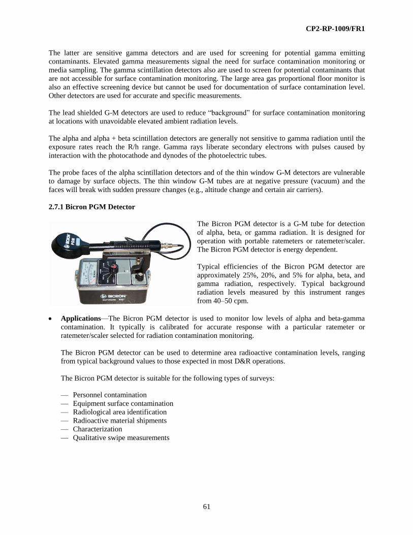
CP2-RP-1009/FR1
61
The latter are sensitive gamma detectors and are used for screening for potential gamma emitting
contaminants. Elevated gamma measurements signal the need for surface contamination monitoring or
media sampling. The gamma scintillation detectors also are used to screen for potential contaminants that
are not accessible for surface contamination monitoring. The large area gas proportional floor monitor is
also an effective screening device but cannot be used for documentation of surface contamination level.
Other detectors are used for accurate and specific measurements.
The lead shielded G-M detectors are used to reduce “background” for surface contamination monitoring
at locations with unavoidable elevated ambient radiation levels.
The alpha and alpha + beta scintillation detectors are generally not sensitive to gamma radiation until the
exposure rates reach the R/h range. Gamma rays liberate secondary electrons with pulses caused by
interaction with the photocathode and dynodes of the photoelectric tubes.
The probe faces of the alpha scintillation detectors and of the thin window G-M detectors are vulnerable
to damage by surface objects. The thin window G-M tubes are at negative pressure (vacuum) and the
faces will break with sudden pressure changes (e.g., altitude change and certain air carriers).
2.7.1 Bicron PGM Detector
The Bicron PGM detector is a G-M tube for detection
of alpha, beta, or gamma radiation. It is designed for
operation with portable ratemeters or ratemeter/scaler.
The Bicron PGM detector is energy dependent.
Typical efficiencies of the Bicron PGM detector are
approximately 25%, 20%, and 5% for alpha, beta, and
gamma radiation, respectively. Typical background
radiation levels measured by this instrument ranges
from 40–50 cpm.
Applications—The Bicron PGM detector is used to monitor low levels of alpha and beta-gamma
contamination. It typically is calibrated for accurate response with a particular ratemeter or
ratemeter/scaler selected for radiation contamination monitoring.
The Bicron PGM detector can be used to determine area radioactive contamination levels, ranging
from typical background values to those expected in most D&R operations.
The Bicron PGM detector is suitable for the following types of surveys:
— Personnel contamination
— Equipment surface contamination
— Radiological area identification
— Radioactive material shipments
— Characterization
— Qualitative swipe measurements
CP2-RP-1009/FR1
62
Additional Features and Auxiliary Equipment—There are no auxiliary features for the Bicron
PGM detector. There is no auxiliary equipment for this detector.
Design Features/Parameters
— Energy Response—This detector responds to radiation energies that are greater than 3 MeV
alpha, 45 kV beta, and 6 kV gamma.
— Gamma Sensitivity—The detector sensitivity to gamma (Cs-137) radiation is approximately
3,600 cpm/mR/h.
— G-M Tube—This detector is a gas-filled “pancake” or flattened cup-shaped shell (cathode) made
of cast aluminum and a wire ring (anode), covered by a thin mica window.
— Operating Voltage—This detector typically is calibrated to operate at approximately 900 volts.
— Shielding—The detector has no shielding.
— Window—The mica window typically is 1.4–2.0-mg/cm2 thick, with an active area of
approximately 2.3 inches2 (15.2 cm
2), covered by a Be/Cu protective mesh screen.
Limits and Precautions
— The detector window is susceptible to punctures and tears. The Bicron PGM detector should be
placed on its side when not in use or placed in an appropriate sample holder or jig to protect the
window.
— The Bicron PGM detector will reach saturation in radiation fields above 5 R/h.
— The Bicron PGM detector is sensitive to gamma radiation fields; care should be exercised when
making alpha/beta measurements in areas where elevated background gamma radiation fields
exist.
Operation
— Determine the type(s) of contamination to be surveyed. Ensure that the detector is suitable for the
type(s) of contamination to be surveyed. Ensure the detector is connected to an instrument that is
suitable for the type of contamination.
— Confirm that the Bicron PGM detector has a current and legible calibration label; if not, remove
from service and do not use until the condition is corrected.
— Determine the radiological contamination levels of interest. Historical, job process, and other
work documents should provide information regarding radionuclides and types of contamination
expected. This information is available from the RCT supervisor and typically is provided on the
RWP for the survey(s) to be performed. This will assist in the proper selection of instrumentation.
— Ensure that daily instrument performance tests have been satisfactorily completed (all readings
are within the defined acceptable range) and documented on a daily test sheet or perform those
tests in accordance with established procedure.

CP2-RP-1009/FR1
63
— Ensure that the detector is connected properly to the instrument and that the cable connections are
in good working order.
— Follow the operation guide instructions for the instrument that is connected to the detector.
2.7.2 Bicron TPGM Detector
The Bicron PGM “pancake” series of portable G-M detectors may be equipped with different shielding
and window locations.
Back-shielded versions may have the shielding constructed of aluminum [aluminum portable G-M
(APGM)], tungsten (TPGM), or lead [lead portable G-M (LPGM)]. The TPGM is the more commonly
used detector , so it is discussed in this operations guide. The principle of operation is the same regardless
of the shielding material.
The Bicron TPGM detector is a tungsten-shielded G-M tube for detection of alpha, beta, or gamma
radiological contamination. This detector is designed for operation with portable ratemeters or
ratemeter/scaler. This detector is energy dependent.
Typical efficiencies of this detector are approximately 25%, 20%, and 5% for alpha, beta, and gamma
radiation, respectively. Typical background radiation levels measured by this instrument range from
40–50 cpm.
Applications—The Bicron PGM series of G-M detectors are used to monitor low levels of alpha and
beta-gamma contamination. They typically are calibrated for accurate response with a particular
ratemeter or ratemeter/scaler selected for radiological contamination monitoring.
The Bicron PGM series of G-M detectors can be used to determine area radioactive contamination
levels, ranging from typical background values to those expected in most D&R operations. They can
be used to determine area radioactive contamination levels, ranging from typical background values
to those expected in most D&R operations.
The Bicron PGM series of G-M detectors are suitable for the following types of surveys:
— Personnel contamination
— Equipment surface contamination
— Radiological area identification
— Radioactive material shipments
— Characterization
— Qualitative swipe measurements
Additional Features and Auxiliary Equipment—There are no auxiliary features for the Bicron
PGM series of G-M detectors. There is no auxiliary equipment associated with these detectors.
Design Features/Parameters
— Energy Response—This detector responds to radiation energies that are greater than 3 MeV,
alpha; 45 keV, beta; and 6 keV, gamma.

CP2-RP-1009/FR1
64
— Gamma Sensitivity—The detector sensitivity to gamma (Cs-137) radiation is approximately
3,600 cpm/mR/h.
— G-M Tube—This detector is a gas-filled “pancake,” or flattened cup-shaped shell (cathode)
made of cast aluminum and a wire ring (anode), covered by a thin mica window.
— Operating Voltage—This detector typically is calibrated to operate at approximately 900 volts.
— Shielding—The detector has a lead shield surrounding the cast aluminum cathode (housing)
shell.
— Window—The mica window typically is 1.4–2.0-mg/cm2 thick, with an active area of
approximately 2.4 inches2 (15.5 cm
2), covered by a Be/Cu mesh screen.
Limits and Precautions
— The detector window is susceptible to punctures and tears. This detector should be placed on its
side when not in use or placed in an appropriate sample holder or jig to protect the window.
— This detector will reach saturation in radiation fields above 5 R/h.
— This detector is sensitive to gamma radiation fields; care should be exercised when making
alpha/beta measurements in areas where elevated background gamma radiation fields exist.
Operation
— Determine the type(s) of contamination to be surveyed. Ensure that the detector is suitable for the
type(s) of contamination to be surveyed. Ensure the detector is connected to an instrument that is
suitable for the type of contamination. Historical, job process, and other work documents should
provide information regarding radionuclides and types of contamination expected. This
information is available from the RCT supervisor and typically is provided on the RWP for the
survey(s) to be performed. This will assist in the proper selection of instrumentation.
— Ensure that the instrument has a current and legible calibration label; if not, remove from service
and do not use until the condition is corrected.
— Ensure that daily instrument performance tests have been satisfactorily completed (all readings
are within the defined acceptable range) and documented on a daily test sheet or perform those
tests in accordance with established procedure.
— Ensure that the detector is connected properly to the instrument and that the cable connections are
in good working order.
— Follow the operation guide instructions for the instrument that is connected to the detector.

CP2-RP-1009/FR1
65
2.7.3 Ludlum Model 44-2 and Eberline
SPA-8 NaI Gamma Scintillators
The Ludlum Model 44-2 and Eberline
SPA-8 detectors virtually are identical NaI
scintillation crystals coupled to
photomultiplier tubes for detection of high
energy, low activity gamma radiation.
These detectors are designed for operation
with portable ratemeters or
ratemeter/scaler. The Ludlum Model 44-2 and Eberline SPA-8 detectors are energy dependent. Because
of their similarities, this operations guide details the operation of the Ludlum 44-2. Where appropriate,
details of the Eberline SPA-8 are included.
Typical efficiency of this type of detector is approximately 250 cpm/μR/h for Cs-137. The typical
background gamma radiation level measured by this instrument is approximately 900–1,000 cpm.
Applications—The Ludlum Model 44-2 detector is used to monitor low levels of gamma
contamination. This detector typically is calibrated for accurate response with a particular ratemeter
or ratemeter/scaler selected for radiation monitoring.
The Ludlum Model 44-2 detector can be used to determine area radiation levels, ranging from typical
background values to those expected in some operations. This instrument is suitable for the following
types of surveys:
— Radiological area identification
— Characterization
Additional Features and Auxiliary Equipment—There are no auxiliary features for the Ludlum
Model 44-2 and Eberline SPA-8 detectors. There is no auxiliary equipment for the Ludlum Model
44-2 and Eberline SPA-8 detectors.
Design Features/Parameters
— Efficiency—The Ludlum Model 44-2 detector has an efficiency of less than 1% for Cs-137.
— Energy Response—The Ludlum Model 44-2 detector responds to gamma radiation energies
ranging from 40 keV–1.2 MeV.
— Operating Voltage—The Ludlum Model 44-2 detector typically is calibrated to operate at
approximately 900-1200 volts.
— Scintillator—The Ludlum Model 44-2 detector is a 1-inch x 1-inch diameter NaI (Tl) crystal
coupled to a magnetically shielded 10-decade photomultiplier tube.
— Shielding—The Ludlum Model 44-2 detector has no shielding.

CP2-RP-1009/FR1
66
Operation
— Determine the type(s) of radiation to be surveyed. Ensure that the detector is suitable for the
type(s) of radiation to be surveyed. Ensure the detector is connected to an instrument that is
suitable for the type of radiation. Historical, job process, and other work documents should
provide information regarding radionuclides and types of contamination expected. This
information is available from the RCT supervisor and typically is provided on the RWP for the
survey(s) to be performed. This will assist in the proper selection of instrumentation.
— Ensure that the instrument has a current and legible calibration label; if not, remove from service
and do not use until the condition is corrected.
— Ensure that daily instrument performance tests have been satisfactorily completed (all readings
are within the defined acceptable range) and documented on a daily test sheet or perform those
tests in accordance with established procedure.
— Ensure that the Ludlum Model 44-2 detector is connected properly to the instrument and that the
cable connections are in good working order.
— Follow the operation guide instructions for the instrument that is connected to the detector.
2.7.4 Ludlum Model 43-5 Alpha Scintillator
The Ludlum Model 43-5 detector is a zinc-sulfide scintillation crystal coupled to a magnetically shielded
photomultiplier tube for detection of alpha radiation. It is designed for operation with portable ratemeters
or ratemeter/scaler. The Ludlum Model 43-5 detector is not energy dependent.
Typical efficiencies of the Ludlum Model 43-5 detector
are approximately 12% for Th-230 and for Pu-239 (4 Pi)
on contact. Typical background alpha radiation
measured by the Ludlum Model 43-5 detector is
approximately 3 cpm.
Applications—The Ludlum Model 43-5 detector is
used to monitor low levels of alpha contamination.
It typically is calibrated for accurate response with a particular ratemeter or ratemeter/scaler selected
for radiological contamination monitoring.
The Ludlum Model 43-5 detector can be used to determine area radioactive contamination levels,
ranging from typical background values to those expected in most operations. The Ludlum Model 43-
5 detector is suitable for the following types of surveys:
— Personnel contamination
— Equipment surface contamination
— Radiological area identification
— Radioactive material shipments
— Characterization
— Qualitative swipe measurements
Additional Features and Auxiliary Equipment—There are no auxiliary features for the Ludlum
Model 43-5 detector. There is no auxiliary equipment for the Ludlum Model 43-5 detector.

CP2-RP-1009/FR1
67
Design Features/Parameters
— Energy Response—The Ludlum Model 43-5 detector responds to alpha radiation energies that
are greater than 3 MeV.
— Gamma Sensitivity—The Ludlum Model 43-5 detector is sensitive to gamma radiation fields
above 1 R/h.
— Operating Voltage—The Ludlum Model 43-5 detector typically is calibrated to operate at
approximately 500-1,000 volts.
— Scintillation Crystal—The Ludlum Model 43-5 detector is a silver-activated zinc-sulfide ZnS
(Ag) scintillation crystal. A 1.5-inch diameter photomultiplier tube converts the resultant
scintillator-produced photons to a measurable electronic pulse.
— Shielding—The Ludlum Model 43-5 detector has no shielding.
— Window—For indoor use, the window typically is two layers of 0.4-mg/cm2 thick aluminized
Mylar, with an active area of 76 cm2, covered by a protective mesh screen. For outdoor use, the
window typically is three layers of 0.4-mg/cm2 thick aluminized Mylar. The sensitive or open
window area is 50 cm2.
Limitations and Precautions—The detector window is susceptible to punctures and tears. The
Ludlum Model 43-5 detector should be placed on its side when not in use or placed in an appropriate
sample holder or jig to protect the window.
Operation
— Ensure that the Ludlum Model 43-5 detector is suitable for the type(s) of contamination to be
surveyed. Ensure the detector is connected to an instrument that is suitable for the type of
contamination.
— Confirm that the Ludlum Model 43-5 detector has a current and legible calibration label; if not,
remove from service and do not use until the condition is corrected.
— Determine the radiological contamination level of interest. Historical, job process, and other work
documents should provide information regarding radionuclides and types of contamination
expected. This information is available from the RCT supervisor and typically is provided on the
RWP for the survey(s) to be performed. This will assist in the proper selection of instrumentation.
— Ensure that daily instrument performance tests have been satisfactorily completed (all readings
are within the defined acceptable range) and documented on a daily test sheet or perform those
tests in accordance with established procedure.
— Ensure that the Ludlum Model 43-5 detector is connected properly to the instrument and that the
cable connections are in good working order.
— When transporting the Ludlum Model 43-5 detector or when not in use, a protective plastic cover
should be used to protect against damage of the fragile Mylar detector face.

CP2-RP-1009/FR1
68
— When used outdoors the Ludlum Model 43-5 detector must have the triple layer 1.2-mg/cm2 thick
Mylar window. The standard Mylar supplied by the manufacture is for indoor use and will cause
the detector to saturate when exposed to direct sunlight.
— If the alpha scintillator indicates an overload condition when positioned in direct sunlight,
reposition the probe away from direct sunlight. If the probe does not continue to indicate an
overload condition while performing surface scanning, static measurements, or frisking of
personnel, then it is considered operational. If the instrument remains in an overload condition
while performing these functions, then the light leak is unacceptable and must be repaired.
— Black lacquer can be used to repair minor light leaks in the field. A performance check must be
performed after any such repair to ensure that the instrument is performing within the specified
criteria. Document the performance check on the daily test sheet.
— Follow the operation guide instructions for the instrument that is connected to the detector. All
instruments used with the Ludlum Model 43-5 detector must have a properly adjusted overload
circuit that indicates when the detector is saturated due to a light leak.
2.7.5 Ludlum Model 43-10-1
The Ludlum Model 43-10-1 is a scintillator/zinc sulfide phoswich
detector. The detector is a 6.4 cm (2.5 in.) diameter “phoswich” with 0.25
mm (0.010 in.) thick plastic scintillator coated with zinc sulfide. The
sample tray is capable of holding up to a 5.1 cm (2 inch) diameter filter or
planchet.
Typical efficiencies of the Ludlum Model 43-10-1 detector are
approximately 32% for Th-230, 37% for Pu-239, and 27% for Tc-99
(4 Pi). Typical background alpha radiation measured by the Model
43-10-1 detector is ≤ 3 counts per minute. Typical background
beta-gamma radiation measured by the Model 43-10-1 detector is
≤ 80 counts per minute beta-gamma.
Applications—The Model 43-10-1 detector is commonly used with alpha/beta dual channel scalers,
such as the Ludlum Model 2224-1, Ludlum Model 2929, and Ludlum Model 3030E. ZnS (Ag) is
used for alpha radiation detection, while the plastic scintillator is used for detection of beta radiation.
When used with the appropriate alpha/beta scaler, the Ludlum Model 43-10-1 detector can be used to
determine:
— Equipment surface contamination
— Radiological area identification
— Radioactive material shipments
— Characterization
— Quantitative smear sample measurements

CP2-RP-1009/FR1
69
Design Features/Parameters
— Efficiency (4π)—37% for 239
PU, 5% for 14
C, 27% for 99
Tc, 32% for 230
Th, 39% for 238
U, 29% for 137
Cs, 26% for 99
Sr/90
Y.
— Sensitivity—≤ 80 cpm beta-gamma and ≤ 3 cpm alpha (in ambient background of 10µR/h)
— Operating Voltage—The Ludlum Model 43-10-1 detector typically is calibrated to operate at
between 500-1,200 volts.
— Shielding—The Ludlum Model 43-10-1 detector has no shielding and should be used in a low
background area.
Limitations and Precautions
— Do not tip the sample counter over with the sample holder in the sample slide. The sample holder
will tear the thin metalized Mylar window, allowing light to scintillate the ZnS and cause
excessive count in the beta channel. The detector window is susceptible to punctures and tears.
— Samples/smears greater than 1000 dpm/100cm2 alpha and 5000 dpm/100cm
2 beta-gamma should
not be counted on the detector to lessen the chance of contaminating the detector.
— Special care should be taken to ensure that sample media does not protrude above the top of the
sample tray when operating the sample slide to prevent the Mylar window from being torn.
— Before counting sample media, ensure the planchet in the detector sample tray is not
contaminated.
Operation
— Ensure the detector is connected to an instrument capable of simultaneous alpha-beta
discrimination.
— Confirm that the instrument has a current and legible calibration label and lists the appropriate
detector serial number; if not, remove from service and do not use until the condition is corrected.
— Ensure that daily instrument performance tests have been satisfactorily completed (all readings
are within the defined acceptable range) and documented on a daily test sheet or perform those
tests in accordance with established procedure.
— Ensure that the Ludlum Model 43-10-1 detector is connected properly to the instrument and that
the cable connections are in good working order.
— Follow the operation guide instructions for the instrument that is connected to the detector.

CP2-RP-1009/FR1
70
2.7.6 Ludlum Model 43-37/43-37-1 Detectors and Model 239-1 Floor Monitor
The Ludlum Models 43-37 and 43-37-1 detectors are large area gas
proportional detectors used for detecting alpha and beta-gamma
radiological contamination levels on floors. They are designed for
operation with portable ratemeter/scaler. The Ludlum Models 43-
37 and 43-37-1 detectors are designed for use with a Ludlum
Model 239-1 Floor Monitor. The Ludlum Model 239-1 Floor
Monitor is a portable cart assembly that holds the ratemeter/scaler,
gas cylinder, two-stage gas regulator, flow meter, and detector. The
cart assembly is designed to allow for adjustment of detector
distance from the floor surface.
The Model 43-37 detector has an active window area of
approximately 582 cm2. The Model 43-37-1 has a larger active
window area of approximately 730 cm2. This operation guide
only describes the operation of the Model 239-1 Floor Monitor
utilizing a Model 43-37 detector because operating principles
and performance are virtually the same for both detectors.
Typical alpha efficiencies of the Model 43-37 detector are
approximately 15% for Th-230 and 17% for Pu-239. Typical
background alpha radiation measured by this instrument is
approximately 2–6 cpm. Typical beta-gamma efficiency of
this detector is 60% for Cs-137. Background beta-gamma radiation measured by this detector is
approximately 800-1,500 cpm.
Applications—The Ludlum Models 43-37 and 43-37-1 detectors are used to monitor low levels of
alpha and beta contamination. They typically are calibrated for accurate response with a particular
ratemeter/scaler selected for radiation contamination monitoring.
The Ludlum Models 43-37 and 34-37-1 detectors can be used to determine area radioactive
contamination levels, ranging from typical background values to those expected in most operations.
The Ludlum Models 43-37 and 43-37-1 detectors are suitable for the following types of surveys:
— Radiological area identification
— Characterization
Additional Features and Auxiliary Equipment—There are no auxiliary features for the Ludlum
Models 43-37 and 43-37-1 detectors. There is no auxiliary equipment for the Ludlum Models 43-37
and 43-37-1 detectors.
Design Features/Parameters
— Detector Height—The distance from the detector to the floor surface is fully adjustable from
0.0125–3.0 inches.
— Detector—The Ludlum Models 43-37 and 43-37-1 detectors are gas-proportional type detectors
that utilize P-10 (10% methane, 90% argon) counting gas.
— Energy Response—The Ludlum Models 43-37 and 43-37-1 detectors respond to alpha radiation

CP2-RP-1009/FR1
71
energies that are greater than 3 MeV, beta radiation energies greater than 150 keV and all gamma
radiation energies.
— Flow Meter Valves—The input and output valves are two-stage pressure regulators typically are
adjusted to provide a gas flow rate of 3–50 cc/min after purging.
— Gas Consumption—Typical flow rate for this detector is 20–30 cc/min.
— Gas Cylinder—The cylinder typically used is either a Matheson size-2 or Linde Q cylinder. The
cylinder always must be stored in its upright position and properly restrained to prevent tip-over.
— Gas Recharge—This detector will operate on static charge for approximately two hours.
— Operating Voltage—The Ludlum Models 43-37 and 43-37-1 detectors typically are calibrated to
operate at approximately 1,000–1,200 volts when measuring alpha radiation and 1,600–1,800
volts when measuring beta-gamma radiation.
— Sensitivity—The Ludlum Model 43-37 and 43-37-1 detectors are sensitive to gamma radiation
fields from 0.1-2 MeV. They are sensitive to thermal neutron radiation fields.
— Shielding—The Ludlum Model 43-37 and 43-37-1 detectors have no shielding.
— Window—The window typically is 0.8-mg/cm2 thick aluminized Mylar for making alpha and
beta-gamma measurements, with an active area of approximately 582 cm2, covered by a
protective mesh screen. The sensitive or open window area is approximately 425 cm2. When
performing measurements for beta-gamma radiation, the window material should consist of a
layer of aluminized Mylar and a layer of Mylar to obtain a window thickness of 3.9 mg/cm2.
Limits and Precautions
— The detector’s window is susceptible to punctures and tears that will cause gas leakage and
serious degradation of counting efficiency.
— If this detector is not purged adequately, the response will not be uniform over the surface of the
detector. This detector may be used when disconnected from the gas source for brief periods,
provided approximate performance is ensured. See Operation section for further details.
— Gas quick connect plastic dust covers always should be in place when the quick connects are not
connected to the Ludlum Models 43-37 and 43-37-1 detectors.
— The Ludlum Models 43-37 and 43-37-1 detectors utilize a gas cylinder under high pressure. Use
care when connecting and transporting new cylinders. Ensure that cylinder protective caps on
unused cylinders are in place and that all cylinders are securely chained, strapped, or otherwise
secured at all times.
Operation
— Ensure that the detector is suitable for the type(s) of contamination to be surveyed.
— Ensure the detector is connected to an instrument that is suitable for the type of contamination.
— Confirm that the Ludlum Models 43-37 and 43-37-1 detectors have a current and legible

CP2-RP-1009/FR1
72
calibration label; if not, remove from service and do not use until condition is corrected.
— Determine the radiation energy range of interest. Historical, job process, and other work
documents should provide information regarding radionuclides and types of contamination
expected. This information is available from the RCT supervisor and typically is provided on the
RWP for the survey(s) to be performed. This will assist in the proper selection of instrumentation.
— Ensure that the detector is disconnected from the instrument.
— Ensure that the gas quick connects are securely connected to the detector.
— Turn the valve on the gas cylinder to the full open position. The cylinder pressure should be
indicated on the regulator gauge.
— Turn the outlet pressure regulator valve clockwise to register 0.5–1.0 psig. Open the flow meter
valve on the input flow meter.
— Open the small needle valve on the regulator ¼ of a turn.
— Check that the gas flow is approximately 80–100 cc/min for purging the detector. If not, adjust
the flow meter valve to establish a gas flow of 80–100 cc/min.
— Ensure that the outlet flow meter is reading within 5 cc/min of the inlet flow. If not, remove from
service until corrected.
— Purge the detector for one hour.
— When the purge is complete, reduce the gas flow to 30–50 cc/min.
— Connect the detector to the ratemeter/scaler instrument, and ensure that the cable connections are
in good working order.
— Perform daily instrument performance tests and document on a daily test sheet.
— Adjust the detector distance to the floor surface per survey procedure requirements.
— Follow the operation guide instructions from the instrument that is connected to the detector.
— Although not recommended for routine operation, once fully purged, the detector may be
disconnected from the gas source for up to two hours for circumstances which prevent use with
gas cylinders. The length of time the detector will maintain adequate performance is dependent
upon the integrity of the gas seals. If operated in a disconnected mode, performance should be
tested (source response) at a minimum of hourly. If the performance is outside the acceptable
range, data collected since the last acceptable test can be used.

CP2-RP-1009/FR1
73
2.7.7 Ludlum Model 43-65 Alpha Scintillator
The Ludlum Model 43-65 detector is a zinc-sulfide
scintillation crystal coupled to a magnetically shielded
photomultiplier tube for detection of alpha radiation. It is
designed for operation with portable ratemeters or
ratemeter/scaler. The Ludlum Model 43-65 detector is not
energy dependent.
Typical efficiencies are approximately 17% for Th-230 and
20% for Pu-239 for the Ludlum Model 43-65 detector.
Typical background alpha radiation measured by this
instrument is approximately 3 cpm.
Applications—The Ludlum Model 43-65 detector is used to monitor low levels of alpha
contamination. This detector typically is calibrated for accurate response with a particular ratemeter
or ratemeter/scaler selected for radiation contamination monitoring.
The Ludlum Model 43-65 detector can be used to determine area radioactive contamination levels,
ranging from typical background values to those expected in most operations. The Ludlum Model 43-
65 detector is suitable for the following types of surveys:
— Personnel contamination
— Equipment surface contamination
— Radiological area identification
— Radioactive material shipments
— Characterization
— Qualitative swipe measurements
Additional Features and Auxiliary Features—There are no auxiliary features for the Ludlum
Model 43-65 detector. There is no auxiliary equipment for the Ludlum Model 43-65 detector.
Design Features/Parameters
— Energy Response—The Ludlum Model 43-65 detector responds to alpha radiation energies that
are greater than 3 MeV.
— Gamma Sensitivity—The Ludlum Model 43-65 detector is sensitive to gamma radiation fields
greater than 1 mR/h.
— Operating Voltage—The Ludlum Model 43-65 detector typically is calibrated to operate at
approximately 500-1,000 volts.
— Scintillation Crystal—The Ludlum Model 43-65 detector is a ZnS (Ag) scintillation crystal. A
1.5-inch diameter photomultiplier tube converts the resultant scintillator-produced photons to a
measurable electronic pulse.
— Shielding—The Ludlum Model 43-65 detector has no shielding.

CP2-RP-1009/FR1
74
— Window—The window typically is two layers of 0.4-mg/cm2 thick aluminized Mylar, with an
active area of 63 cm2, covered by a protective mesh screen. The sensitive or open window area is
50 cm2.
Limits and Precautions—The detector’s window is susceptible to punctures and tears. The Ludlum
Model 43-65 detector should be placed on its side when not in use or placed in an appropriate sample
holder or jig to protect the window.
Operation
— Ensure that the Ludlum Model 43-65 detector is suitable for the type(s) of contamination to be
surveyed. Ensure the detector is connected to an instrument that is suitable for the type of
contamination.
— Confirm that the Ludlum Model 43-65 detector has a current and legible calibration label; if not,
remove from service and do not use until the condition is corrected.
— Determine the radiological contamination levels of interest. Historical, job process, and other
work documents should provide information regarding radionuclides and types of contamination
expected. This information is available from the RCT supervisor and typically is provided on the
RWP for the survey(s) to be performed. This will assist in the proper selection of instrumentation.
— Ensure that daily instrument performance tests have been satisfactorily completed (all readings
are within the defined acceptable range) and documented on a daily test sheet or perform those
tests in accordance with established procedure.
— Ensure that the detector is connected properly to the instrument and that the cable connections are
in good working order.
— Follow the operation guide instructions for the instrument that is connected to the detector.
2.7.8 Ludlum Model 43-68 Gas Proportional Detector
The Ludlum Model 43-68 is a gas proportional detector used for detecting alpha and beta radiation. It is
designed for operation with portable ratemeter/scaler.
The Model 43-68 has an active window area of approximately 126 cm2.
Typical alpha efficiencies of the Model 43-68 detector are approximately
15% for Th-230 and 20% for Pu-239. Typical background alpha radiation
measured by this instrument is less than 7 cpm. Typical beta efficiency of
this detector is 30% for both Tc-99 and Sr-90. Background beta radiation
measured by this detector is approximately 350 cpm.
Applications—The Ludlum Model 43-68 detector is used to monitor
low levels of alpha and beta contamination. The Ludlum Model 43-68
detector typically is calibrated for accurate response with a particular
ratemeter/scaler selected for radiation contamination monitoring.
The Ludlum Model 43-68 detector can be used to determine area
radioactive contamination levels, ranging from typical background values to those expected in most

CP2-RP-1009/FR1
75
operations. The Ludlum Model 43-68 detector is suitable for the following types of surveys:
— Radiological area identification
— Characterization
Additional Features and Auxiliary Equipment—There are no additional features for the Ludlum
Model 43-68 detector. The Ludlum Model 43-68 detector requires a gas supply (cylinder), two-stage
pressure regulator, and flow meter for operation.
Design Features/Parameters
— Detector—The Ludlum Model 43-68 detector is a gas-proportional type detector that utilizes
P-10 (10% methane, 90% argon) counting gas.
— Energy Response—The Ludlum Model 43-68 detector responds to alpha radiation energies that
are greater than 3 MeV and beta radiation energies greater than 150 keV.
— Flow Meter Valves—The input and output valves are two-stage pressure regulators typically are
adjusted to provide a gas flow rate of 30-50 cc/min after purging.
— Gas Consumption—Typical flow rate for this detector is 50 cc/min.
— Gas Cylinder—The cylinder typically used is a Matheson size 2 or Linde Q cylinder. Always
change the cylinder when there still is positive pressure on the tank (100-200 PSI) to reduce the
potential for contaminating the cylinder with ambient air. (NOTE: Gas cylinders always must be
stored in their upright position and properly restrained to prevent tip-over.)
— Gas Recharge—The Ludlum Model 43-68 detector will operate on static charge for
approximately 5–15 hours, depending on the mode of use.
— Operating Voltage—The Ludlum Model 43-68 detector typically is calibrated to operate at
approximately 1100–1400 volts when measuring alpha radiation and 1600–1800 volts when
measuring beta radiation.
— Sensitivity—The Ludlum Model 43-68 detector is sensitive to gamma radiation fields from
0.1–2 MeV. This detector is sensitive to thermal neutron radiation fields.
— Shielding—The Ludlum Model 43-68 detector has no shielding.
— Window—The window typically is 0.8-mg/cm2 thick aluminized Mylar for making alpha and
beta-gamma measurements, with an active area of approximately 126 cm2, covered by a
protective mesh screen. The sensitive or open window area is approximately 100 cm2.
Limits and Precautions
— The detector’s window is susceptible to punctures and tears that will cause gas leakage and
serious degradation of counting efficiency.
CP2-RP-1009/FR1
76
— If the Ludlum Model 43-68 detector is not purged adequately, the response will not be uniform
over the surface of the detector. This detector may be used when disconnected from the gas
source for brief periods, provided appropriate performance is ensured. See the Operation section
for further details.
— Plastic dust covers should always be in place when the gas quick connects is not connected to the
Ludlum Model 43-68 detector.
— The Ludlum Model 43-68 detector utilizes double-end shut-off quick connects. Both the male and
female connectors must be connected to allow gas to flow through the detector.
Operation
— Ensure that the Ludlum Model 43-68 detector is suitable for the type(s) of contamination to be
surveyed. Ensure the Ludlum Model 43-68 detector is connected to an instrument that is suitable
for the type of contamination.
— Confirm that the Ludlum Model 43-68 detector has a current and legible calibration label; if not,
remove from service and do not use until the condition is corrected.
— Determine the radiological contamination of interest. Historical, job process, and other work
documents should provide information regarding radionuclides and types of contamination
expected. This information is available from the RCT supervisor and typically is provided on the
RWP for the survey(s) to be performed. This will assist in the proper selection of instrumentation.
— Ensure that the Ludlum Model 43-68 detector is disconnected from the instrument.
— Ensure that the gas quick connects are securely connected to the detector. Turn the valve on the
gas cylinder to the full open position. The cylinder pressure should be indicated on the regulator
gauge.
— Turn the outlet pressure regulator valve clockwise to register 0.5-1.0 psig.
— Open the flow meter valve on the input flow meter.
— Open the small needle valve on the regulator ¼ of a turn.
— Check that the gas flow is approximately 80–100 cc/min for purging the detector. If not, adjust
the flow meter valve to that range.
— Ensure that the outlet flow meter is reading within 5 cc/min of the inlet flow. If not, remove from
service and do not use until the condition is corrected.
— Purge the detector for 15 minutes.
— When the purge is complete, reduce the inlet gas flow to 30–50 cc/min.
— Connect the detector the instrument and ensure that the cable connections are in good working
order.
— Perform daily instrument performance tests and document on a daily test sheet.

CP2-RP-1009/FR1
77
— Follow the operation guide instructions for the instrument that is connected to the detector.
— Although not recommended for routine operation, once fully purged, the detector may be
disconnected from the gas source for up to two hours for circumstances which prevent use with
gas hoses. The length of time the detector will maintain adequate performance is dependent upon
the integrity of the gas seals. If operated in a disconnected mode, performance should be tested
(source response) at a minimum of hourly. If the performance is outside the acceptable range,
data collected since the last acceptable test cannot be used.
2.7.9 Ludlum Model 43-89 and 43-93 Alpha/Beta Scintillators
Ludlum Model 43-89
Ludlum Model 43-93
The Ludlum Model 43-89 and Model 43-93 detectors are essentially the same detector, except for size
variation in the active area of the window and counting efficiency. This detector type is a zinc-sulfide
scintillation crystal and a plastic scintillator coupled to a magnetically shielded photomultiplier tube for
simultaneous detection of alpha and beta radiation. This phosphor type of detector is designed for
operation with portable ratemeters or ratemeter/scaler. The Ludlum Model 43-89 and Model 43-93
detectors may be used for alpha or beta discrimination measurements when calibrated with the dual or
multichannel ratemeter/scaler. Differences in the three models are described in this operations guide, as
appropriate. This operations guide primarily is written for the more widely used Model 43-89 detector.
Typical alpha efficiencies for these detector models are approximately 16%–22% for Th-230 and 18%–
20% for Pu-239. Typical background alpha radiation measured by these detectors is approximately 3 cpm.
Typical beta efficiencies of these detector models are 16%–18% for Sr-90 and 10%–11% for Tc-99.
Typical background beta radiation measured by this instrument type is approximately 200-300 cpm.
Applications—The Ludlum Model 43-89 detector is used to monitor low levels of alpha and beta
contamination. It typically is calibrated for accurate response with a particular ratemeter or
ratemeter/scaler selected for radiation contamination monitoring.
The Ludlum Model 43-89 detector can be used to determine area radioactive contamination levels,
ranging from typical background values to those expected in most operations. The Ludlum Model 43-
89 detector is suitable for the following types of surveys:
— Personnel contamination
— Equipment surface contamination
— Radiological area identification
— Radioactive material shipments

CP2-RP-1009/FR1
78
— Characterization
— Qualitative swipe measurements
Additional Features and Auxiliary Equipment—There are no auxiliary features for the Ludlum
Model 43-89 detector. There is no auxiliary equipment for the Ludlum Model 43-89 detector.
Design Features/Parameters
— Energy Response—The Ludlum Model 43-89 detector responds to alpha radiation energies that
are greater than 3 MeV and beta radiation energies that are greater than 150 keV.
— Gamma Sensitivity—The Ludlum Model 43-89 detector is sensitive to gamma radiation fields
above 1 R/h.
— Operating Voltage—The Ludlum Model 43-89 detector typically is calibrated to operate at
approximately 500–1,000 volts.
— Scintillator—The Ludlum Model 43-89 detector is a 0.01-inch rectangular plastic scintillator
mounted with ZnS (Ag). A 1.5-inch diameter photomultiplier tube converts the resultant
scintillator-produced photons to a measurable electronic pulse.
— Shielding—The Ludlum Model 43-89 detector has no shielding.
— Window—The window typically is 1.2-mg/cm2 thick aluminized Mylar (0.8 mg/cm
2 for Model
43-93), with an active area of 125 cm2 (100 cm
2 for the Model 43-93), covered by a protective
mesh screen. The sensitive or open window area is 100 cm2 (90 cm
2 for the Model 43-93).
Limits and Precautions—The detector’s window is susceptible to punctures and tears. The Ludlum
Model 43-89 detector should be placed on its side when not in use or placed in an appropriate sample
holder or jig to protect the window.
Operation
— Ensure that the Ludlum Model 43-89 detector is suitable for the type(s) for contamination to be
surveyed. Ensure the detector is connected to an instrument that is suitable for the type of
contamination.
— Confirm that the Ludlum Model 43-89 detector has a current legible calibration label; if not,
remove from service and do not use until condition is corrected.
— Determine the radiological contamination levels of interest. Historical, job process, and other
work documents should provide information regarding radionuclides and types of contamination
expected. This information is available from the RCT supervisor and typically is provided on the
RWP for the survey(s) to be performed. This will assist in the proper selection of instrumentation.
— Ensure that daily instrument performance tests have been completed satisfactorily (all readings
are within the defined acceptable range) and documented on a daily test sheet or perform those
tests in accordance with established procedure.

CP2-RP-1009/FR1
79
— Ensure that the Ludlum Model 43-89 detector is connected properly to the instrument and that the
cable connections are in good working order.
— Follow the operation guide instructions for the instrument that is connected to the detector.
2.7.10 Ludlum Model 44-9 Geiger-Müeller Detector
The Ludlum Model 44-9 detector is a G-M tube for
detection of alpha, beta, or gamma radiation. The
Ludlum Model 44-9 detector is designed for operation
with portable ratemeters or ratemeter/scales. It is
energy dependent.
Typical efficiencies of the Ludlum Model 44-9
detector are approximately 25%, 20%, and 5% for alpha, beta, and gamma radiation, respectively. Typical
background radiation levels measured by this instrument range from 40–50 cpm.
Applications—The Ludlum Model 44-9 detector is used to monitor low levels of alpha and beta-
gamma contamination. It typically is calibrated for accurate response with a particular ratemeter or
ratemeter/scaler selected for radiological contamination monitoring.
The Ludlum Model 44-9 detector can be used to determine area radioactive contamination levels,
ranging from typical background values to those expected in most operations. The Ludlum Model 44-
9 detector can be used to determine area radioactive contamination levels, ranging from typical
background values to those expected in most operations.
The Ludlum Model 44-9 detector is suitable for the following types of surveys:
— Personnel contamination
— Equipment surface contamination
— Radiological area identification
— Radioactive material shipments
— Characterization
— Qualitative swipe measurements
Additional Features and Auxiliary Equipment—The detector also is available with a telescoping
handle; this unit is similar in all other specifications to Model 44-9 and is designated as Model
44-9-18.
Design Features/Parameters
— Energy Response—The Ludlum Model 44-9 detector responds to radiation energies that are
greater than 3 MeV, alpha; 45 keV, beta; and 6 keV, gamma.
— Gamma Sensitivity—The Ludlum Model 44-9 detector sensitivity to gamma (Cs-137) radiation
is approximately 3,300 cpm/mR/h.
— G-M Tube—The Ludlum Model 44-9 detector is a gas-filled “pancake” or flattened cup-shaped
shell (cathode) made of cast aluminum and a wire ring (anode), covered by a thin mica window.
CP2-RP-1009/FR1
80
— Operating Voltage—The Ludlum Model 44-9 detector typically is calibrated to operate at
approximately 900 volts.
— Shielding—The Ludlum Model 44-9 detector has no shielding.
— Window—The mica window typically is 1.4–2.0-mg/cm2
thick with an active area of
approximately 2.3 inches2 (15.2 cm
2), covered by a protective mesh screen.
Limits and Precautions
— The detector’s window is susceptible to punctures and tears. The Ludlum Model 44-9 detector
should be placed on its side when not in use or placed in an appropriate sample holder or jig to
protect the window.
— The Ludlum Model 44-9 detector will reach saturation in radiation fields above 5 R/h.
— The Ludlum Model 44-9 detector is sensitive to gamma radiation fields; care should be exercised
when making alpha/beta measurements in areas where elevated background gamma radiation
fields exist.
Operation
— Determine the type(s) of contamination to be surveyed. Ensure that the Ludlum Model 44-9
detector is suitable for the type(s) of contamination to be surveyed. Ensure the Ludlum Model
44-9 detector is connected to an instrument that is suitable for the type of contamination.
— Determine the radiological contamination levels of interest. Historical, job process, and other
work document should provide information regarding radionuclides and types of contamination
expected. This information is available from the RCT supervisor and typically is provided on the
RWP for the survey(s) to be performed. This will assist in the proper selection of instrumentation.
— Ensure that daily instrument performance tests have been satisfactorily completed (all readings
are within the defined acceptable range) and documented on a daily test sheet or perform those
tests in accordance with established procedure.
— Ensure that the Ludlum Model 44-9 detector is connected properly to the instrument and that the
cable connections are in good working order.
— Follow the operation guide instructions for the instrument that is connected to the detector.

CP2-RP-1009/FR1
81
2.7.11 Ludlum Models 44-3, 44-10, and 44-17 Gamma Scintillators
Ludlum Model 44-3
Ludlum Model 44-10
Ludlum Model 44-17
These Ludlum detectors incorporate a NaI scintillation crystal coupled to a photomultiplier tube for
detection of high energy, low activity gamma radiation. It is designed for operation with portable
ratemeters or ratemeter/scaler. These detectors are energy dependent.
Typical sensitivity:
Ludlum Model 44-3 detector is approximately 675 cpm/µR/hr for I-125, typical background is 400 cpm.
Ludlum Model 44-10 detector is approximately 900 cpm/μR/h for Cs-137, typical background is
900–1,000 cpm.
Ludlum Model 44-17 typical background is 1,400 cpm.
Applications—These detectors are used to monitor low levels of gamma contamination. They
typically are calibrated for accurate response with a particular ratemeter or scaler selected for
radiation monitoring.
These detectors can be used to determine area radiation levels, ranging from typical background
values to those expected in some operations. These detectors are suitable for the following types of
surveys:
— Radiological area identification
— Characterization
— Contaminated wound counting
Additional Features and Auxiliary Equipment—There are no auxiliary features for these detectors.
Design Features/Parameters
— Efficiency
– The Ludlum Model 44-3 detector has an efficiency of approximately 19% for I-125.
– The Ludlum Model 44-10 detector has an efficiency of approximately 75% for Cs-137.
– The Ludlum Model 44-17 detector has an efficiency of approximately 20% for I-125.

CP2-RP-1009/FR1
82
— Energy Response
– The Ludlum Model 44-3 detector responds to gamma radiation energies ranging from
10–60 keV.
– The Ludlum Model 44-10 detector responds to gamma radiation energies ranging from
60 keV–2 MeV.
– The Ludlum Model 44-17 detector responds to gamma radiation energies ranging from
10–200 keV.
— Scintillator
– The Ludlum Model 44-3 detector is a 1-inch x 1-inch diameter NaI (Tl) crystal coupled to a
magnetically shielded 10-decade photomultiplier tube.
– The Ludlum Model 44-10 detector is a 2-inch x 2-inch diameter NaI (Tl) crystal coupled to a
magnetically shielded 10-decade photomultiplier tube.
– The Ludlum Model 44-17 detector is a 2-inch x 2-inch diameter NaI (Tl) crystal coupled to a
magnetically shielded 10-decade photomultiplier tube.
— Shielding—These detectors have no shielding.
Operation
— Determine the type(s) of radiation to be surveyed. Ensure that the detector is suitable for the
type(s) of contamination to be surveyed. Ensure the detector is connected to an instrument that is
suitable for the type of radiation. Historical, job process, and other work documents should
provide information regarding radionuclides and types of contamination expected. This
information is available from the RCT supervisor and typically is provided on the RWP for the
surveys to be performed. This will assist in the proper selection of instrumentation.
— Ensure that the Ludlum Model 44-10 detector has a current and legible calibration label; if not,
remove from service and do not use until condition is corrected.
— Ensure that daily instrument performance tests have been satisfactorily completed (all readings
are within the defined acceptable range) and documented on a daily test sheet or perform those
tests in accordance with established procedure.
— Ensure that the Ludlum Model 44-10 detector is connected properly to the instrument and that the
cable connections are in good working order.
— Follow the operation guide instructions for the instrument that is connected to the detector.
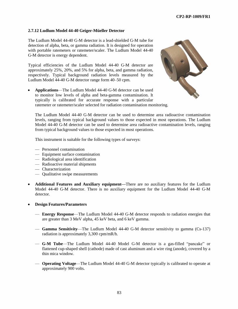
CP2-RP-1009/FR1
83
2.7.12 Ludlum Model 44-40 Geiger-Müeller Detector
The Ludlum Model 44-40 G-M detector is a lead-shielded G-M tube for
detection of alpha, beta, or gamma radiation. It is designed for operation
with portable ratemeters or ratemeter/scaler. The Ludlum Model 44-40
G-M detector is energy dependent.
Typical efficiencies of the Ludlum Model 44-40 G-M detector are
approximately 25%, 20%, and 5% for alpha, beta, and gamma radiation,
respectively. Typical background radiation levels measured by the
Ludlum Model 44-40 G-M detector range form 40–50 cpm.
Applications—The Ludlum Model 44-40 G-M detector can be used
to monitor low levels of alpha and beta-gamma contamination. It
typically is calibrated for accurate response with a particular
ratemeter or ratemeter/scaler selected for radiation contamination monitoring.
The Ludlum Model 44-40 G-M detector can be used to determine area radioactive contamination
levels, ranging from typical background values to those expected in most operations. The Ludlum
Model 44-40 G-M detector can be used to determine area radioactive contamination levels, ranging
from typical background values to those expected in most operations.
This instrument is suitable for the following types of surveys:
— Personnel contamination
— Equipment surface contamination
— Radiological area identification
— Radioactive material shipments
— Characterization
— Qualitative swipe measurements
Additional Features and Auxiliary equipment—There are no auxiliary features for the Ludlum
Model 44-40 G-M detector. There is no auxiliary equipment for the Ludlum Model 44-40 G-M
detector.
Design Features/Parameters
— Energy Response—The Ludlum Model 44-40 G-M detector responds to radiation energies that
are greater than 3 MeV alpha, 45 keV beta, and 6 keV gamma.
— Gamma Sensitivity—The Ludlum Model 44-40 G-M detector sensitivity to gamma (Cs-137)
radiation is approximately 3,300 cpm/mR/h.
— G-M Tube—The Ludlum Model 44-40 Model G-M detector is a gas-filled “pancake” or
flattened cup-shaped shell (cathode) made of cast aluminum and a wire ring (anode), covered by a
thin mica window.
— Operating Voltage—The Ludlum Model 44-40 G-M detector typically is calibrated to operate at
approximately 900 volts.

CP2-RP-1009/FR1
84
— Shielding—The Ludlum Model 44-40 G-M detector has a lead shield surrounding the cast
aluminum cathode (housing) shell.
— Window—The mica window typically is 1.4-2.0-mg/cm2 thick with an active area of
approximately 2.3 inches (15.2 cm), covered by a protective mesh screen.
Limitations and Precautions
— The detector’s window is susceptible to punctures and tears. The Ludlum Model 44-40 G-M
detector should be placed on its side when not in use or placed in an appropriate sample holder or
jig to protect the window.
— The Ludlum Model 44-40 G-M detector will reach saturation in radiation fields above 5 R/h.
— The Ludlum Model 44-40 G-M detector is sensitive to gamma radiation fields; care should be
exercised when making alpha/beta measurements in areas where elevated background gamma
radiation fields exist.
Operation
— Determine the type(s) of contamination to be surveyed. Ensure that the Ludlum Model 44-40
G-M detector is suitable for the type(s) of contamination to be surveyed. Ensure the Ludlum
Model 44-40 G-M detector is connected to an instrument that is suitable for the type of
contamination.
— Confirm that the Ludlum Model 44-40 G-M detector has a current and legible calibration label; if
not, remove from service and do not use until the condition is corrected.
— Determine the radiological contamination levels of interest. Historical, job process, and other
work documents should provide information regarding radionuclides and types of contamination
expected. This information is available from the RCT supervisor and typically is provided on the
RWP for the survey(s) to be performed. This will assist in the proper selection of instrumentation.
— Ensure that daily instrument performance tests have been satisfactorily completed (all readings
are within the defined acceptable range) and documented on a daily test sheet or perform those
tests in accordance with established procedure.
— Ensure that the Ludlum Model 44-40 G-M detector is connected properly to the instrument and
that the cable connections are in good working order.
— Follow the operation guide instructions for the instrument that is connected to the detector.
2.7.13 NE Technology DP6-CD Alpha/Beta Scintillator
The NE Technology (now Thermo Electron Corporation)
DP-6CD detector is a 100cm2 zinc-sulfide scintillator
mounted on a plastic scintillator coupled to a
magnetically shielded photomultiplier tube for
simultaneous detection of alpha and beta radiation. This
phosphor type of detector is designed for operation with
portable ratemeters or ratemeter/scaler. The NE

CP2-RP-1009/FR1
85
Technology DP-6CD detector may be used for alpha or beta discrimination measurements when
calibrated with the dual or multichannel ratemeter/scaler.
Typical alpha efficiencies of the NE Technology DP-6CD detector are approximately 30% for Am-241,
17% for Th-230, and 20% for Pu-239. Typical background alpha radiation measured by this instrument is
approximately 6 cpm. Typical beta efficiencies of this detector are 20% for Sr-90 and 10% for Tc-99.
Typical background beta radiation measured by the NE Technology DP-6CD detector is approximately
360 cpm.
Applications—The NE Technology DP-6CD detector is used to monitor low levels of alpha and beta
contamination. It typically is calibrated for accurate response with a particular ratemeter or
ratemeter/scaler selected for radiation contamination monitoring.
The NE Technology DP-6CD detector can be used to determine area radioactive contamination
levels, ranging from typical background values to those expected in most operations.
The NE Technology DP-6CD detector is suitable for the following types of surveys:
— Personnel contamination
— Equipment surface contamination
— Radiological area identification
— Radioactive material shipments
— Characterization
— Qualitative swipe measurements
Additional Features and Auxiliary Equipment—There are no auxiliary features for the NE
Technology DP-6CD detector. There is no auxiliary equipment for the NE Technology DP-6CD
detector.
Design Features/Parameters
— Energy Response—The NE Technology DP-6CD detector responds to alpha radiation energies
that are greater than 3 MeV and beta radiation energies that are greater than 150 keV.
— Gamma Sensitivity—The NE Technology DP-6CD detector is sensitive to gamma radiation
fields above one R/h.
— Operating Voltage—The NE Technology DP-6CD Detector typically is calibrated to operate at
approximately 900 volts.
— Scintillator—The NE Technology DP-6CD Detector is a 0.01-inch rectangular plastic scintillator
mounted with ZnS(Ag). A 1.5-inch diameter photomultiplier tube converts the resultant
scintillator-produced photons to a measurable electronic pulse.
— Shielding—The NE Technology DP-6CD Detector has no shielding.
— Window—The window typically is 1.2-mg/cm2 thick aluminized Mylar, with an active area of
100 cm2, covered by a protective mesh screen. The sensitive or open window area is 65 cm
2.

CP2-RP-1009/FR1
86
Limits and Precautions—The detector’s window is susceptible to punctures and tears. The NE
Technology DP-6CD should be placed on its side when not in use or placed in an appropriate sample
holder or jig to protect the window.
Operation
— Determine the type(s) of contamination to be surveyed. Ensure that the NE Technology DP-6CD
detector is suitable for the type(s) of contamination to be surveyed. Ensure the NE Technology
DP-6CD detector is connected to an instrument that is suitable for the type of contamination.
— Confirm that the NE Technology DP-6CD detector has a current and legible calibration label; if
not, remove from service and do not use until the condition is corrected.
— Determine the radiological contamination levels of interest. Historical, job process, and other
work documents should provide information regarding radionuclides and types of contamination
expected. This information is available from the RCT supervisor and typically is provided on the
RWP for the survey(s) to be performed. This will assist in the proper selection of instrumentation.
— Ensure that daily instrument performance tests have been satisfactorily completed (all readings
are within the defined acceptable range) and documented on a daily test sheet or perform those
tests in accordance with established procedure.
— Ensure that the NE Technology DP-6CD detector is connected properly to the instrument and that
the cable connections are in good working order.
— Follow the operation guide instructions for the instrument that is connected to the detector.
2.7.14 NE Technology DP-6BD Alpha/Beta Scintillator
The NE Technology (now Thermo Electron Corporation) DP-6BD detector is a 100cm2 zinc-sulfide
scintillator mounted on a plastic scintillator coupled to a magnetically shielded photomultiplier tube for
simultaneous detection of alpha and beta radiation. This phosphor type of detector is designed for
operation with portable ratemeters or ratemeter/scaler. The NE Technology DP-6BD detector may be
used for alpha or beta discrimination measurements when calibrated with the dual or multichannel
ratemeter/scaler. While similar to the DP-6CD, the DP-6BD does not have a signal gain control that
allows simulating GM detectors requiring +900 volts.
Typical alpha efficiencies of the NE Technology DP-6BD detector are approximately 17% for Th-230
and 20% for Pu-239. Typical background alpha radiation measured by this instrument is approximately 6
cpm. Typical beta efficiencies of this detector are 20% for Sr-90 and 10% for Tc-99. Typical background
beta radiation measured by the NE Technology DP-6BD detector is approximately 360 cpm.
Applications—The NE Technology DP-6BD detector is used to monitor low levels of alpha and beta
contamination. It typically is calibrated for accurate response with a particular ratemeter or
ratemeter/scaler selected for radiation contamination monitoring.
The NE Technology DP-6BD detector can be used to determine area radioactive contamination
levels, ranging from typical background values to those expected in most operations.
The NE Technology DP-6BD detector is suitable for the following types of surveys:

CP2-RP-1009/FR1
87
— Personnel contamination
— Equipment surface contamination
— Radiological area identification
— Radioactive material shipments
— Characterization
— Qualitative swipe measurements
Additional Features and Auxiliary Equipment—There are no auxiliary features for the NE
Technology DP-6BD detector. There is no auxiliary equipment for the NE Technology DP-6BD
detector.
Design Features/Parameters
— Energy Response—The NE Technology DP-6BD detector responds to alpha radiation energies
that are greater than 3 MeV and beta radiation energies that are greater than 150 keV.
— Gamma Sensitivity—The NE Technology DP-6BD detector is sensitive to gamma radiation
fields above one R/h.
— Operating Voltage—The NE Technology DP-6BD Detector typically is calibrated to operate at
approximately 900 volts.
— Scintillator—The NE Technology DP-6BD Detector is a 0.01-inch rectangular plastic scintillator
mounted with ZnS(Ag). A 1.5-inch diameter photomultiplier tube converts the resultant
scintillator-produced photons to a measurable electronic pulse.
— Shielding—The NE Technology DP-6BD Detector has no shielding.
— Window—The window typically is 1.2-mg/cm2 thick aluminized Mylar, with an active area of
100 cm2, covered by a protective mesh screen. The sensitive or open window area is 65 cm
2.
Limits and Precautions—The detector’s window is susceptible to punctures and tears. The NE
Technology DP-6BD should be placed on its side when not in use or placed in an appropriate sample
holder or jig to protect the window.
Operation
— Determine the type(s) of contamination to be surveyed. Ensure that the NE Technology DP-6BD
detector is suitable for the type(s) of contamination to be surveyed. Ensure the NE Technology
DP-6BD detector is connected to an instrument that is suitable for the type of contamination.
— Confirm that the NE Technology DP-6BD detector has a current and legible calibration label; if
not, remove from service and do not use until the condition is corrected.
— Determine the radiological contamination levels of interest. Historical, job process, and other
work documents should provide information regarding radionuclides and types of contamination
expected. This information is available from the RCT supervisor and typically is provided on the
RWP for the survey(s) to be performed. This will assist in the proper selection of instrumentation.

CP2-RP-1009/FR1
88
— Ensure that daily instrument performance tests have been satisfactorily completed (all readings
are within the defined acceptable range) and documented on a daily test sheet or perform those
tests in accordance with established procedure.
— Ensure that the NE Technology DP-6BD detector is connected properly to the instrument and that
the cable connections are in good working order.
— Follow the operation guide instructions for the instrument that is connected to the detector.
2.7.15 Bicron Model G5 Scintillation Detector
The Bicron Model G5 detector commonly is referred to as a FIDLER probe (field instrument for the detection of low
energy radiation), is a large area, NaI scintillation detector
that is optimized to detect low energy X-rays and gamma
radiation. The Bicron Model G5 detector is designed for
operation with portable ratemeters, ratemeters/scalers, or
SCAs. It is energy dependent.
Typical efficiency of the Bicron Model G5 detector is
approximately 6% for low energy X-rays and gamma
radiation between 10–100 keV.
Typical background radiation levels measured by this instrument ranges from 5,000–6,000 cpm.
Applications—The Bicron Model G5 detector is used to detect low energy X-rays and gamma
radiation. It typically is calibrated for accurate response with the particular ratemeter or
ratemeter/scaler selected for radiation monitoring.
The Bicron Model G5 detector can be used to determine radiation levels, ranging from typical
background values to those expected in most operations. The Bicron Model G5 detector is suitable for
the following types of surveys:
— Radiological area identification
— Characterization
Additional Features and Auxiliary Equipment—Horizontal and vertical carrying handles also are
available.
Design Features/Parameters
— Energy Response—The Bicron Model G5 detector responds to low energy X-ray and gamma
radiation energies ranging from 10–100 keV.
— Operating Voltage—The Bicron Model G5 detector is designed to operate at a maximum of
1,600 volts and typically is operated at approximately 1,000 volts.
— Shielding—The Bicron Model G5 Detector has no shielding.
— Scintillation Crystal—The Bicron Model G5 Detector has a NaI (Tl) crystal that is 127 mm in
diameter and 1.6-mm thick.

CP2-RP-1009/FR1
89
— Window—The Bicron Model G5 detector has a beryllium window that is 127 mm in diameter
and 0.254-mm thick.
Limits and Precautions
— The detector’s beryllium window is susceptible to punctures. The Bicron Model G5 detector
should be placed on its side when not in use.
— The efficiency of the Bicron Model G5 detector drops off rapidly for photon radiation above
100 keV.
— The Bicron Model G5 detector has a temperature operating range from 39°F to 109°F.
Operation
— Determine the type(s) of contamination to be surveyed. Ensure that the Bicron Model G5 detector
is suitable for the type(s) of contamination to be surveyed. Ensure the Bicron Model G5 detector
is connected to an instrument that is suitable for the type of contamination.
— Confirm that the Bicron Model G5 detector has a current and legible calibration label; if not,
remove from service and do not use until the condition is corrected.
— Determine the radiological contamination levels of interest. Historical, job process, and other
work documents should provide information regarding radionuclides and types of contamination
expected.
— This information is available from the RCT supervisor and typically is provided on the RWP for
the survey(s) to be performed. This will assist in the proper selection of instrumentation.
— Ensure that daily instrument performance tests have been satisfactorily completed (all readings
are within the defined acceptable range) and documented on a daily test sheet or perform those
tests in accordance with established procedure.
— Ensure that the Bicron Model G5 detector is connected properly to the instrument and that the
cable connections are in good working order.
— Follow the operation guide instructions for the instrument that is connected to the detector.
2.8 PERSONAL AIR SAMPLERS
Air monitoring is an important component of any radiation protection program and is linked to bioassay
and respiratory protection programs. A number of procedures and technical basis documents contribute to
the overall internal dosimetry program. The air sampling requirements will be designated in RWPs or
other project authorization documents.
Initial and routine assessments are based on comparison to the derived air concentrations (DACs) within
Appendix A of 10 CFR § 835. Working in an airborne concentration of one DAC for one hour is
estimated to result in a committed effective dose of 2.5 mrem for the radionuclides of concern at uranium
facilities. Some procedures have conditional actions or controls based on DAC-hr including 12 DAC-hr
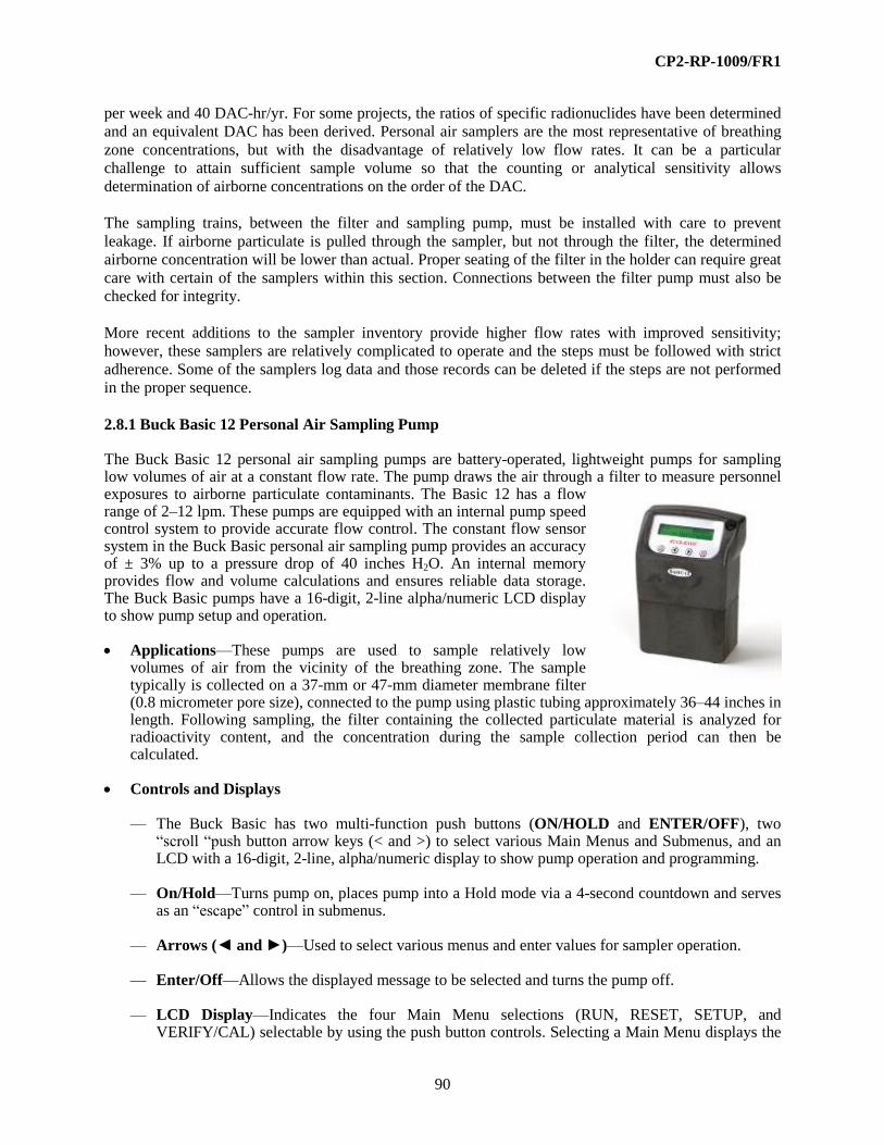
CP2-RP-1009/FR1
90
per week and 40 DAC-hr/yr. For some projects, the ratios of specific radionuclides have been determined
and an equivalent DAC has been derived. Personal air samplers are the most representative of breathing
zone concentrations, but with the disadvantage of relatively low flow rates. It can be a particular
challenge to attain sufficient sample volume so that the counting or analytical sensitivity allows
determination of airborne concentrations on the order of the DAC.
The sampling trains, between the filter and sampling pump, must be installed with care to prevent
leakage. If airborne particulate is pulled through the sampler, but not through the filter, the determined
airborne concentration will be lower than actual. Proper seating of the filter in the holder can require great
care with certain of the samplers within this section. Connections between the filter pump must also be
checked for integrity.
More recent additions to the sampler inventory provide higher flow rates with improved sensitivity;
however, these samplers are relatively complicated to operate and the steps must be followed with strict
adherence. Some of the samplers log data and those records can be deleted if the steps are not performed
in the proper sequence.
2.8.1 Buck Basic 12 Personal Air Sampling Pump The Buck Basic 12 personal air sampling pumps are battery-operated, lightweight pumps for sampling low volumes of air at a constant flow rate. The pump draws the air through a filter to measure personnel exposures to airborne particulate contaminants. The Basic 12 has a flow range of 2–12 lpm. These pumps are equipped with an internal pump speed control system to provide accurate flow control. The constant flow sensor system in the Buck Basic personal air sampling pump provides an accuracy of ± 3% up to a pressure drop of 40 inches H2O. An internal memory provides flow and volume calculations and ensures reliable data storage. The Buck Basic pumps have a 16-digit, 2-line alpha/numeric LCD display to show pump setup and operation. Applications—These pumps are used to sample relatively low
volumes of air from the vicinity of the breathing zone. The sample typically is collected on a 37-mm or 47-mm diameter membrane filter (0.8 micrometer pore size), connected to the pump using plastic tubing approximately 36–44 inches in length. Following sampling, the filter containing the collected particulate material is analyzed for radioactivity content, and the concentration during the sample collection period can then be calculated.
Controls and Displays — The Buck Basic has two multi-function push buttons (ON/HOLD and ENTER/OFF), two
“scroll “push button arrow keys (< and >) to select various Main Menus and Submenus, and an LCD with a 16-digit, 2-line, alpha/numeric display to show pump operation and programming.
— On/Hold—Turns pump on, places pump into a Hold mode via a 4-second countdown and serves as an “escape” control in submenus.
— Arrows (◄ and ►)—Used to select various menus and enter values for sampler operation.
— Enter/Off—Allows the displayed message to be selected and turns the pump off.
— LCD Display—Indicates the four Main Menu selections (RUN, RESET, SETUP, and VERIFY/CAL) selectable by using the push button controls. Selecting a Main Menu displays the
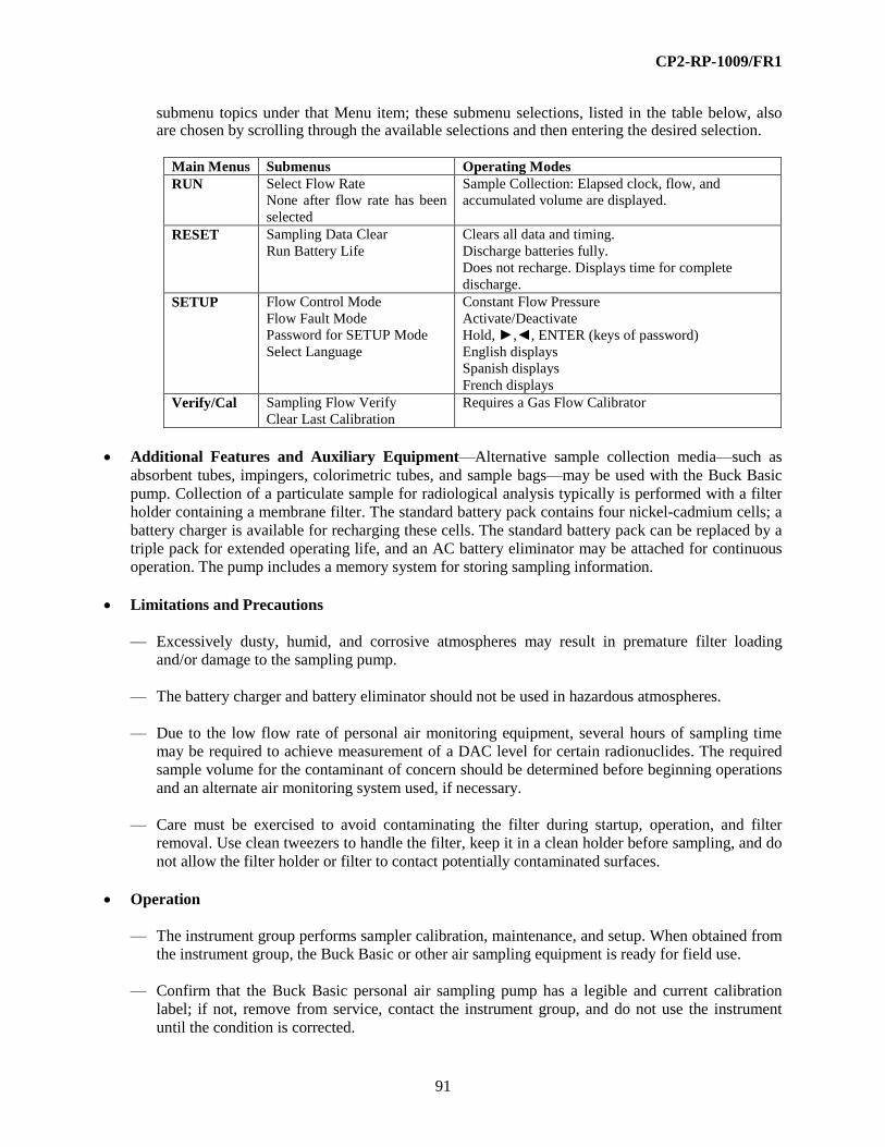
CP2-RP-1009/FR1
91
submenu topics under that Menu item; these submenu selections, listed in the table below, also are chosen by scrolling through the available selections and then entering the desired selection.
Main Menus Submenus Operating Modes
RUN Select Flow Rate
None after flow rate has been
selected
Sample Collection: Elapsed clock, flow, and
accumulated volume are displayed.
RESET Sampling Data Clear
Run Battery Life
Clears all data and timing.
Discharge batteries fully.
Does not recharge. Displays time for complete
discharge.
SETUP Flow Control Mode
Flow Fault Mode
Password for SETUP Mode
Select Language
Constant Flow Pressure
Activate/Deactivate
Hold, ►,◄, ENTER (keys of password)
English displays
Spanish displays
French displays
Verify/Cal Sampling Flow Verify
Clear Last Calibration
Requires a Gas Flow Calibrator
Additional Features and Auxiliary Equipment—Alternative sample collection media—such as
absorbent tubes, impingers, colorimetric tubes, and sample bags—may be used with the Buck Basic
pump. Collection of a particulate sample for radiological analysis typically is performed with a filter
holder containing a membrane filter. The standard battery pack contains four nickel-cadmium cells; a
battery charger is available for recharging these cells. The standard battery pack can be replaced by a
triple pack for extended operating life, and an AC battery eliminator may be attached for continuous
operation. The pump includes a memory system for storing sampling information.
Limitations and Precautions
— Excessively dusty, humid, and corrosive atmospheres may result in premature filter loading
and/or damage to the sampling pump.
— The battery charger and battery eliminator should not be used in hazardous atmospheres.
— Due to the low flow rate of personal air monitoring equipment, several hours of sampling time
may be required to achieve measurement of a DAC level for certain radionuclides. The required
sample volume for the contaminant of concern should be determined before beginning operations
and an alternate air monitoring system used, if necessary.
— Care must be exercised to avoid contaminating the filter during startup, operation, and filter
removal. Use clean tweezers to handle the filter, keep it in a clean holder before sampling, and do
not allow the filter holder or filter to contact potentially contaminated surfaces.
Operation
— The instrument group performs sampler calibration, maintenance, and setup. When obtained from
the instrument group, the Buck Basic or other air sampling equipment is ready for field use.
— Confirm that the Buck Basic personal air sampling pump has a legible and current calibration
label; if not, remove from service, contact the instrument group, and do not use the instrument
until the condition is corrected.

CP2-RP-1009/FR1
92
— Historical data, job process, and other work documents should provide information regarding
radionuclides and types of contamination expected. This information is available from the RCT
supervisor and typically is provided on the RWP for the survey(s) to be performed. This will
assist in the proper selection of flow rate, sample media, and sample analysis parameters.
— Ensure filter holder is attached to sampling pump with tubing; ensure the filter holder contains a
new/undamaged membrane filter. Affix the pump and the filter holder to the individual being
monitored or place in a suitable location.
— Turn the instrument on by pressing the ON/HOLD button.
— Scroll to “Reset” on display. Press ENTER. Scroll to “Sample Data Clear;” press ENTER.
This sequence clears all data and timing and automatically cycles the Main Menu to “Run.”
— With the Main Menu display on “Run,” press ENTER. Check to be sure the displayed flow rate
is as indicated on the calibration label; if not, scroll to the flow rate indicated on the label and
press ENTER.
— After the flow rate has been selected, press ENTER to begin sampling. Record start time, flow
rate data, identity (name/badge number) of individual wearing sampler, and identification of
others, if any, being monitored by same pump (one pump may be used to estimate potential
exposure to airborne contaminants of up to five individuals depending on specific work
conditions) on the air sample envelope.
— Press the > arrow button to display the estimated available sampling time based on battery
capacity and flow settings selected.
— During operation, remaining battery capacity, elapsed time, flow rate, and accumulated volume
are displayed on the LCD.
— When sampling is complete, record the finish time, elapsed time, flow rate, and accumulated
volume data on the air sample envelope. Press the ON/HOLD button, then press ENTER/OFF to
turn the sampler off.
— Remove the filter, place it in a clean air sample envelope, and deliver the filter and sampling
information to the laboratory for analysis. Recharge the sampler if reuse is planned; otherwise,
return the sampling pump to the instrument group.
2.8.2 Buck VSS-12 Personal Air Sampling Pump
The Buck VSS-12 personal air sampling pump (Validated Sampling System)
is a battery-operated, lightweight, programmable pump for sampling low
volumes of air at a constant flow rate. The pump draws the air through a filter
to measure personnel exposures to airborne particulate contaminants. The
unit has a flow range of 2–12 lpm and is equipped with internal sensor
system to provide accurate flow control; this system includes sensors for
differential pressure, pump speed (revolutions per minute), barometric
pressure, and temperature. The constant flow sensor system provides an
accuracy of ± 3% and corrects flow and volume to standard temperature and
pressure. An internal microprocessor provides flow and volume calculations,

CP2-RP-1009/FR1
93
provides programming access, and ensures reliable data storage and downloading capability. The VSS-12
pump has a 16-digit, 2-line alpha/numeric LCD display to show pump operation and programming.
Applications—The Buck VSS-12 personal air sampling pump is used to sample relatively low
volumes of air from the vicinity of the breathing zone. The sample typically is collected on a 45-mm
diameter membrane filter (0.8 micron pore size), connected to the pump using ¼-inch diameter Tygon
tubing approximately 36 inches in length. Following sampling, the filter containing the collected
particulate material is analyzed for radioactivity content and the concentration during the sample
collection period can then be calculated.
Controls and Displays
— The Buck VSS-12 has two multifunction push buttons (ON/HOLD and ENTER/OFF), two
“scroll” push button arrow keys (< and >) to select various main menus and submenus, and LCD
with a 16-digit, 2-line alpha/numeric display to show pump operation and programming.
— Arrows (◄ and ►)—Used to select various menus and enter values for sampler operation.
— Enter/Off—Allows the displayed message to be selected and turns the pump off.
— LCD Display—Indicates the six Main Menu selections (RUN, RESET, FLO/PR, SETUP,
PRINT, CAL) selectable by using the push button controls. Selecting a main menu displays the
submenu topics under that menu item; these submenu selections, listed in the table below, are
also chosen by scrolling through the available selections and then entering the desired selection.
— On/Hold—Turn pump on, places pump into a Hold mode via a 4-second countdown, and serves
as an “Escape” control in submenus.
Table 1. Buck VSS-12 Operating Menus and Submenus
Main Menus Submenus Operating Modes
RUN Select Flow Rater
None after flow rate has been selected
Sample Collection: Elapsed clock, flow, and
accumulated volume are displayed.
RESET Sampling Data Clear
Clear Elapsed Time
Change Flow Rate
Reset Timing Routine
Run Battery Condition
Clears all data and timing.
Only if activated under SETUP
Cycles battery to full discharge. (Does not
recharge automatically.)
FLO/PR Flow Control Mode
Select VOL or STP
PR, Constant Pressure
Volumetric Flow or STP Flow
Flow Pressure selectable in inches of water
pressure 5-21 inches.
SETUP Timing Routines
History Report Logging Rate
Flow Fault Mode
Password for SETUP Mode
Reset Time
Select Unit of Measure
Activate/Deactivate
0-60 minutes
Activate/Deactivate
Hold, ◄, ►, ENTER (keys of password No/Yes
Metric/English
PRINT Print Report Pump History
Delete All Log Entries
Printing Logs
Clears logs for new data. Max. capacity is 800.
Number is displayed when Print is pressed.
CAL Sampling Flow Verify Current Data
Clear Last Calibration
Requires a Primary Gas Flow Calibrator

CP2-RP-1009/FR1
94
Additional Features and Auxiliary Equipment—Alternative sample collection media, such as
absorbent tubes, impingers, colorimetric tubes, and sample bags, may be used with the VSS-12 pump.
Collection of a particulate sample for radiological analysis typically is performed with a filter
cartridge containing a membrane filter. The standard battery pack contains four nickel-cadmium cells;
a battery charger is available for recharging these cells. The standard battery pack can be replaced by
a triple pack for extended operating life, and an AC battery eliminator may be attached for continuous
operation. The Buck VSS-12 personal air sampling pump includes a memory system for storing
sampling information; the stored information can be uploaded to a computer via a special uplink
program or printed directly.
Limitations and Precautions
— Excessively dusty, humid, and corrosive atmospheres may result in premature filter loading
and/or damage to the Buck VSS-12 personal air sampling pump.
— The battery charger and battery eliminator should not be used in hazardous atmospheres.
— Due to the low flow rate of personal air monitoring equipment, several hours of sampling time
may be required to achieve measurement of a DAC level for certain radionuclides. The required
sample volume for the contaminant of concern should be determined before beginning operations
and an alternate air monitoring system used if necessary.
— Care must be exercised to avoid contaminating the filter during startup, operation, and filter
removal. Use clean tweezers to handle the filter, keep it in a clean holder before and after
sampling, and do not allow the filter holder or filter to contact potentially contaminated surfaces.
Operation
— The instrument group performs sampler calibration, maintenance, and setup. When obtained from
the instrument group, the Buck VSS-12 or other air sampling equipment is ready for field use.
— Confirm that the instrument has a legible and current calibration label; if not, remove from
service, return to the instrument group, and do not use the instrument until the condition is
corrected.
— Ensure that the daily instrument performance tests have been satisfactorily completed (all
readings are within the defined acceptable range) and documented on a daily test sheet or perform
those tests in accordance with established procedure.
— Attach filter holder to sampling pump with tubing; ensure the filter holder contains a new,
undamaged membrane filter. Affix the pump and the filter holder to the individual being
monitored.
— Turn the instrument on by pressing the ON/HOLD button.
— Scroll to “Reset” on display. Press ENTER. Scroll to “Clear all Data;” press ENTER. This
sequence clears all data and timing and automatically cycles the Main Menu to “Run.”
— With the Main Menu display on “Run,” press ENTER. Check to be sure the displayed flow rate
is as indicated on the calibration label; if not, scroll to the flow rate indicated on the label and
press ENTER.

CP2-RP-1009/FR1
95
— Press ENTER to begin sampling. Record start time and flow rate data.
— Press the ◄ arrow button to display the battery capacity in units of percent remaining capacity
(this also may be checked at any time during operation). The estimated available sampling time,
based on battery capacity and flow settings selected is also displayed by pressing this key during
the sampling run.
— During operation, elapsed time, flow rate, and accumulated volume are displayed on the LCD.
— When sampling is complete, record the finish time, elapsed time, flow rate, and accumulated flow
data. Press the ON/HOLD button, the press ENTER/OFF to turn off the sampler.
— Remove the filter, place it in a clean envelope, and deliver the filter and sampling information to
the laboratory for analysis.
— Return the sampling pump to the instrument group.
2.8.3 Buck Libra Plus Model LP-12 Personal Air Sampling Pump
The BUCK Libra Plus™ LP-12 personal air sampler consists of a pump contained in a high-impact steel-
fiber-filled Lexan, antistatic, RFI/EMI-shielded case, exclusive electronic
circuit board (patent pending) for constant flow control, an LCD display with 2
lines of 16 characters, a double diaphragm pump mechanism, and a
rechargeable NiMH battery pack. The purpose of this pump is to draw air
contaminants in through a sampling media such as 25-, 37-, and 47-mm filter
cassettes, to gauge personnel exposure to particulates and aerosols.
Applications—The Buck Libra Plus™ LP-12 personal air sampler is used
to sample relatively low volumes of air from the vicinity of the breathing
zone. The sample typically is collected on a 47-mm diameter membrane
filter (0.8 micron pore size), connected to the pump using 3/8-inch diameter
Tygon tubing approximately 36 inches in length. Following sampling, the
filter containing the collected particulate material is analyzed for
radioactivity content and the concentration during the sample collection
period can then be calculated.
Controls and Displays
— The Buck Libra Plus™ LP-12 has an ON/OFF key which also acts as an escape key in submenus.
— SET key, which enables the user to use the arrow keys to change the display value.
— UP/DOWN keys, which operate the display text on the display.
— LCD Display—Indicates the Menu selections (RUN, MENU, and BATTERY CAPACITY)
selectable by using the push button controls. Selecting a main menu displays the submenu topics
under that menu item; these submenu selections, listed in the table below, are also chosen by
scrolling through the available selections and then entering the desired selection.
— Flow Mode—Turn pump on, press and hold the SET key while using the arrows to change the
flow on the display. After selecting the flow, press the ON/OFF key to return to the main display.

CP2-RP-1009/FR1
96
Then press the RUN (up arrow) key to begin sampling.
— Reset Mode— To clear data with the same flow rate, press and hold the SET key and the up
arrow key. A warning displays, and asks for a second Yes. This clears the elapsed time, volume,
timer, and goes to the main display.
— Calibration Mode— The selected flow rate is measured against a calibrator to verify it matches
the Run Mode flow within +/- 5%.
— Timer Mode— Select time by using the arrow for pump to run and turn off automatically. Times
up to 40:00 hours may be selected. The pump must then be manually started. Setting the timer
automatically clears the data.
— Protection Mode— This requires the sequence of pressing the keys in a left to right direction
once, to make the pump turn off. Run mode is the only mode that this function is enabled.
Setting the flow rate:
— Connect sampling filter with a hose to the pump.
— Turn on the pump by pressing the ON key.
— Press the down arrow key to the Flow Adjust Menu.
— Press and hold the SET key, and use the arrows to adjust the flow.
— Releasing the SET key will store the flow rate.
— Press the ON/OFF key to return to the main display.
Pump calibration adjustment:
— Connect the pump to the calibrator.
— From the Main Display, use the down arrow to the calibration mode.
— Press the Set key and release, pump begins to flow at the present flow rate.
— Measure flow. If it matches +/- 5% of the setting, press the ON/OFF key and resume sampling.
— Press and hold the SET key to adjust the factor for the pump speed to match the desired flow rate.
— Press the ON/OFF key to return to the Main Display and begin sampling.
Additional Features and Auxiliary Equipment—Alternative sample collection media, such as
absorbent tubes, impingers, colorimetric tubes, and sample bags, may be used with the LP-12 pump.
Collection of a particulate sample for radiological analysis typically is performed with a filter
cartridge containing a membrane filter. The standard battery pack contains four nickel-cadmium cells;
a battery charger is available for recharging these cells. The standard battery pack can be replaced by
a triple pack for extended operating life, and an AC battery eliminator may be attached for continuous
operation. The Buck Libra Plus™ LP-12 includes a memory system for storing sampling information;
the stored information can be uploaded to a computer via a special uplink program or printed directly.
Limitations and Precautions
— Excessively dusty, humid, and corrosive atmospheres may result in premature filter loading
and/or damage to the Buck Libra Plus™ LP-12.
— The battery charger and battery eliminator should not be used in hazardous atmospheres.

CP2-RP-1009/FR1
97
— Due to the low flow rate of personal air monitoring equipment, several hours of sampling time
may be required to achieve measurement of a DAC level for certain radionuclides. The required
sample volume for the contaminant of concern should be determined before beginning operations
and an alternate air monitoring system used if necessary.
— Care must be exercised to avoid contaminating the filter during startup, operation, and filter
removal. Use clean tweezers to handle the filter, keep it in a clean holder before and after
sampling, and do not allow the filter holder or filter to contact potentially contaminated surfaces.
Operation
— The instrument group performs sampler calibration, maintenance, and setup. When obtained from
the instrument group, the Buck LP-12 or other air sampling equipment is ready for field use.
— Confirm that the instrument has a legible and current calibration label; if not, remove from
service, return to the instrument group, and do not use the instrument until the condition is
corrected.
— Ensure that the daily instrument performance tests have been satisfactorily completed (all
readings are within the defined acceptable range) and documented on a daily test sheet or perform
those tests in accordance with established procedure.
— Attach filter holder to sampling pump with tubing; ensure the filter holder contains a new,
undamaged membrane filter. Affix the pump and the filter holder to the individual being
monitored.
— Turn the instrument on by pressing the ON/HOLD button.
— Press the Down Arrow key to the Flow Adjust Menu.
— Press and hold the SET key, and use the arrows to adjust the flow.
— Releasing the SET key will store the flow rate.
— Press the ON/OFF key to return to the Main Display, and then press the UP ARROW (RUN) to
begin sampling.
— Record start time and flow rate data.
— Press the ◄ arrow button to display the battery capacity in units of percent remaining capacity
(this also may be checked at any time during operation). The estimated available sampling time,
based on battery capacity and flow settings selected is also displayed by pressing this key during
the sampling run.
— During operation, elapsed time, flow rate, and accumulated volume are displayed on the LCD.
— When sampling is complete, record the finish time, elapsed time, flow rate, and accumulated flow
data. Press the ON/OFF button.

CP2-RP-1009/FR1
98
— Remove the filter, place it in a clean envelope, and deliver the filter and sampling information to
the laboratory for analysis.
— Return the sampling pump to the instrument group.
2.8.4 Buck Libra Plus Model LP-7 Personal Air Sampling Pump
The BUCK Libra Plus™ LP-7 personal air sampler
consists of a pump contained in a high-impact steel-fiber-
filled Lexan, antistatic, RFI/EMI-shielded case, exclusive
electronic circuit board (patent pending) for constant flow
control, an LCD display with 2 lines of 16 characters, a
double diaphragm pump mechanism, and a rechargeable
NiMH battery pack. The purpose of this pump is to draw
air contaminants in through a sampling media such as 25-,
37-, and 47-mm filter cassettes, to gauge personnel
exposure to particulates and aerosols.
Applications—The Buck Libra Plus™ LP-7 personal
air sampler is used to sample relatively low volumes
of air from the vicinity of the breathing zone. The
sample typically is collected on a 47-mm diameter
membrane filter (0.8 micron pore size), connected to
the pump using 3/8-inch diameter Tygon® tubing approximately 36 inches in length. Following
sampling, the filter containing the collected particulate material is analyzed for radioactivity content
and the concentration during the sample collection period can then be calculated.
Controls and Displays
— The Buck Libra Plus™ LP-7 has an ON/OFF key which also acts as an escape key in submenus.
— SET key—enables the user to use the arrow keys to change the display value.
— UP/DOWN keys—operate the display text on the display.
— LCD Display—Indicates the Menu selections (RUN, MENU, and BATTERY CAPACITY)
selectable by using the push button controls. Selecting a main menu displays the submenu topics
under that menu item; these submenu selections, listed in the table below, are also chosen by
scrolling through the available selections and then entering the desired selection.
— Flow Mode—Turn pump on, press and hold the SET key while using the arrows to change the
flow on the display. After selecting the flow, press the ON/OFF key to return to the main display.
Then press the RUN (up arrow) key to begin sampling.
— Reset Mode— To clear data with the same flow rate, press and hold the SET key and the up
arrow key. A warning displays, and asks for a second Yes. This clears the elapsed time, volume,
timer, and goes to the main display.
— Calibration Mode— The selected flow rate is measured against a calibrator to verify it matches
the Run Mode flow within +/- 5%.

CP2-RP-1009/FR1
99
— Timer Mode— Select time by using the arrow for pump to run and turn off automatically. Times
up to 40:00 hours may be selected. The pump must then be manually started. Setting the timer
automatically clears the data.
— Protection Mode— This requires the sequence of pressing the keys in a left to right direction
once, to make the pump turn off. Run mode is the only mode that this function is enabled.
Setting the flow rate:
— Connect sampling filter with a hose to the pump.
— Turn on the pump by pressing the ON key.
— Press the down arrow key to the Flow Adjust Menu.
— Press and hold the SET key, and use the arrows to adjust the flow.
— Releasing the SET key will store the flow rate.
— Press the ON/OFF key to return to the main display.
Pump calibration adjustment (performed by the instrument group, when necessary):
— Connect the pump to the calibrator.
— From the Main Display, use the down arrow to the calibration mode.
— Press the Set key and release, pump begins to flow at the present flow rate.
— Measure flow. If it matches +/- 5% of the setting, press the ON/OFF key and resume sampling.
— Press and hold the SET key to adjust the factor for the pump speed to match the desired flow rate.
— Press the ON/OFF key to return to the Main Display and begin sampling.
Additional Features and Auxiliary Equipment—Alternative sample collection media, such as
absorbent tubes, impingers, colorimetric tubes, and sample bags, may be used with the LP-7 pump.
Collection of a particulate sample for radiological analysis typically is performed with a filter
cartridge containing a membrane filter. The standard battery pack contains four nickel-cadmium cells;
a battery charger is available for recharging these cells. The standard battery pack can be replaced by
a triple pack for extended operating life, and an AC battery eliminator may be attached for continuous
operation. The Buck Libra Plus™ LP-7 includes a memory system for storing sampling information;
the stored information can be uploaded to a computer via a special uplink program or printed directly.
Limitations and Precautions
— Excessively dusty, humid, and corrosive atmospheres may result in premature filter loading
and/or damage to the Buck Libra Plus™ LP-7.
— The battery charger and battery eliminator should not be used in hazardous atmospheres.
— Due to the low flow rate of personal air monitoring equipment, several hours of sampling time
may be required to achieve measurement of a DAC level for certain radionuclides. The required
sample volume for the contaminant of concern should be determined before beginning operations
and an alternate air monitoring system used if necessary.
— Care must be exercised to avoid contaminating the filter during startup, operation, and filter
removal. Use clean tweezers to handle the filter, keep it in a clean holder before and after
sampling, and do not allow the filter holder or filter to contact potentially contaminated surfaces.

CP2-RP-1009/FR1
100
Operation
— The instrument group performs sampler calibration, maintenance, and setup. After successful
completion of daily performance tests, the Buck LP-7, or other air sampling equipment is ready
for field use.
— Confirm that the instrument has a legible and current calibration label; if not, remove from
service, return to the instrument group, and do not use the instrument until the condition is
corrected.
— Ensure that the daily instrument performance tests have been satisfactorily completed (all
readings are within the defined acceptable range) and documented on a daily test sheet or perform
those tests in accordance with established procedure.
— Attach filter holder to sampling pump with tubing; ensure the filter holder contains a new,
undamaged membrane filter. Affix the pump and the filter holder to the individual being
monitored.
— Turn the instrument on by pressing the ON/HOLD button.
— Press the Down Arrow key to the Flow Adjust Menu.
— Press and hold the SET key, and use the arrows to adjust the flow.
— Releasing the SET key will store the flow rate.
— Press the ON/OFF key to return to the Main Display, and then press the UP ARROW (RUN) to
begin sampling.
— Record start time and flow rate data.
— Press the ◄ arrow button to display the battery capacity in units of percent remaining capacity
(this also may be checked at any time during operation). The estimated available sampling time,
based on battery capacity and flow settings selected is also displayed by pressing this key during
the sampling run.
— During operation, elapsed time, flow rate, and accumulated volume are displayed on the LCD.
— When sampling is complete, record the finish time, elapsed time, flow rate, and accumulated flow
data. Press the ON/OFF button.
— Remove the filter, place it in a clean envelope, and deliver the filter and sampling information to
the laboratory for analysis.
— Return the sampling pump to the instrument group.

CP2-RP-1009/FR1
101
2.9 LOW-VOLUME AIR SAMPLERS
Low volume air samplers are used to determine airborne concentrations for indoor work areas. These
samplers have much higher flow rates (20–60 lpm) than personal air samplers. Low-volume air samplers
allow greater sensitivity with airborne concentrations down to fractions of a DAC.
Proper positioning of the sampler is important and should consider the following:
Relationship to the worker’s breathing zone,
Expected point or path of the highest airborne concentration, and
Potential airborne releases due to the loss of power or engineered controls.
The sampler location must not interfere with the safety of operations. Airflow paths can be visualized by
the use of smoke tubes.
Reading of the rotameter flow rate is at the center of the ball. This can vary among manufacturers and
facilities; however, our calibrations are performed using the center of the ball as the index.
As with any air sampler, integrity of the sampling trains and proper seating of the filter in the holder is
important.
2.9.1 Hi-Q MRV-1023 CV and MRV-0523C Low Volume Area Air Samplers
The MRV-1023 CV and MRV-0523C low volume area air samplers are low
volume air-sampling pumps. Both air samplers are essentially the same, except
for airflow capacity and flow rate range. The differences are described below.
Most air samplers are equipped with a control panel, an extendable wand
(gooseneck) and wheeled cart; however, some may be hand carried. The
extendable wand allows for collection of air samples nearer to a worker’s
breathing zone. The air sample pump consists of an oilless carbon vane vacuum
pump with a combination filter holder, flow meter, two vacuum gauges and a
constant air flow regulator. The spring-loaded regulator maintains a constant
flow rate by varying the differential pressure across a venturi. The regulator
does not utilize a bypass valve. Only sampled air is exhausted from the pump.
The oilless pump requires no lubrication. The pump motor is mounted on a base
plate with four rubber feet. The pump motor is powered by 110 VAC. The
control panel houses a power ON/OFF toggle switch with fuse protection, the
vacuum gauges, and a re-settable electronic timer.
The MRV-1023CV low volume area air sampler can be equipped with a standard 47 mm combination
filter holder or Whatman-41 AK105 filter card. The MRV-1023 CV low volume air sampler has an
operating flow range of 0–200 lpm; the MRV-0523C has an operating flow range of 0–100 lpm. Flow
rates typically are set at 20–60 lpm, depending on the sampling requirements. These instruments are
equipped with an elapsed time meter.
Applications—The MRV-1023 CV and MRV-0523C Low Volume Area Air Samplers are used for
long-term environmental monitoring and for extended sampling campaigns on some D&R operations.
The air samples typically are collected on 47 mm diameter membrane filter paper or Whatman-41
AK105 filter cards. Following air sample collection, the filter paper is removed for required
CP2-RP-1009/FR1
102
radiological analyses.
Controls and Displays
— Flow Regulator—The constant flow regulator utilizes a spring-loaded diaphragm and flow
venturi to regulate constant airflow. Adjustment is made during flow calibrations to establish
proper flow rate, as required by sampling protocol.
— On-Off—An ON-OFF switch is provided and is located on the control panel.
Additional Features and Auxiliary Equipment—A variety of sample holders and cartridges are
available for use with the MRV-1023 CV Low Volume Area Air Sampler.
Limitations and Precautions
— Fire(s) or explosion(s) can occur if this instrument is operated in explosive or combustible
environment(s).
— Electrical shock or equipment damage can occur if this instrument and the electrical cord are wet
during operation, or if the electrical cord is not properly grounded.
— The pump motor can become very hot when operated for extended periods. Take appropriate
precautions when handling.
— Use appropriate contamination control techniques when handling potentially contaminated filters
or filter holders.
— Care must be exercised to avoid contaminating the filter paper during sample start up, operation,
and filter paper removal. Use clean tweezers to handle the filter; keep the filter in a clean holder
before and after sample collection. Internal surfaces of the motor may become contaminated.
— Dust loading on sample filter may occur in a short time when operating in areas where
particulates are suspended (near grinding or similar operations). Air sample time/volume should
be kept to a minimum in these instances.
— The MRV-1023 CV is not intended for outdoors use during inclement weather.
Operation
— Perform a visual inspection of the air sampler and the electrical cord for physical damage. If
damage is found, remove the instrument from service and do not use until condition is corrected.
— Ensure that the daily instrument performance tests have been satisfactorily completed (all
readings are within the defined acceptable range) and documented on a daily test sheet or perform
those tests in accordance with established procedure, if required.
— Verify that the flow meter has a current and legible calibration label. If not, remove from service
and do not use until the condition is corrected.
— Verify that the rotameter is intact and properly connected. If not, remove from service and do not

CP2-RP-1009/FR1
103
use until the condition is corrected.
— Ensure that an air filter assembly (sample head) is connected properly to the pump.
— Install the air sample filter assembly finger-tight. Once installed, ensure that the air filter is
centered and not creased or folded.
— Locate the air sampler away from normal traffic areas; ensure that the power cord does not
become a tripping hazard.
— Place the power switch to “ON” and record the start date and the time on the Airborne
Contamination envelope. If utilization of a barcode reader is being used to track on/off times and
flow rates, follow the required barcode system protocols to ensure correct interface with the
computer database.
— Adjust the constant flow control valve to obtain the flow rate and record the initial flow rate on
the Airborne Contamination Survey Form or other equivalent form.
— When the air sample is complete, observe the final flow rate, time, and place instrument control
switch to “OFF.”
— Record the date and the time that the sample was completed, the sample duration, and the ending
flow rate on the Airborne Contamination Survey Sheet Form or other equivalent form. Remove
the sample filter assembly by using appropriate contamination control techniques.
2.9.2 SAIC AVS-28A and HD-29A Low Volume Area Air Samplers
The AVS-28A and HD-29A Low Volume Area Air Samples are low
volume, air sampling pumps. Components and equipment are virtually
the same for both units, except the HD-29A is equipped with a control
panel, an extendable wand (gooseneck) and wheeled cart.
The extendable wand allows for collection of air samples closer to a
worker’s breathing zone.
The AVS-28A and HD-29A Low Volume Area Air Samplers consist of
an oilless carbon vane vacuum pump with a combination filter holder,
flow meter, vacuum gauge and a constant air flow regulator. The
spring-loaded regulator maintains a constant flow rate by varying the
differential pressure across a venturi. The regulator does not utilize a
bypass valve. Only sampled air is exhausted from the pump. The oilless
pump requires no lubrication. The pump motor is mounted on a base
plate with four rubber feet. A carrying handle is provided on the
chassis. The AVS-28A and HD-29A pump motors are powered by 110
V AC.
The AVS-28A and HD-29A Low Volume Area Air Samplers can be equipped with a standard 47 mm
combination filter holder. The AVS-28A and HD-29A Low Volume Area Air Samplers have an operating
flow range of 0–100 lpm. Flow rate typically is set at 30–60 lpm. These instruments are equipped with an
elapsed time meter.

CP2-RP-1009/FR1
104
Applications—The AVS-28A and HD-29A Low Volume Area Air Samplers are used for long-term
environmental monitoring and for extended sampling campaigns on some operations. The air samples
typically are collected on 47 mm diameter membrane filter paper or Whatman-41 AK105 filter cards.
Following air sample collection, the filter paper or card is removed for required radiological analyses.
Controls and Displays
— On-Off—An On-Off switch is provided and is located on the rear cover plate of the pump motor
chassis.
— Flow meter—Airflow is indicated by a 10-100 lpm rotameter. The stainless steel ball inside the
rotameter provides the indication of airflow rate.
— Flow Regulator—The constant flow regulator utilizes a spring-loaded diaphragm and flow
venturi to regulate constant airflow. Adjustment is made during flow calibrations to establish
proper flow rate, as required by sampling protocol.
Additional Features and Auxiliary Equipment—A variety of sample holders and cartridges are
available for use with these air samplers.
Limitations and Precautions
— Fire(s) or explosion(s) can occur if this instrument is operated in explosive or combustible
environment(s).
— Electrical shock or equipment damage can occur if this instrument and the electrical cord are wet
during operation, or if the electrical cord is not properly grounded.
— The pump motor can become very hot when operated for extended periods. Take appropriate
precautions when handling.
— Use appropriate contamination control techniques when handling potentially contaminated filters
or filter holders.
— Care must be exercised to avoid contaminating the filter paper during sample start up, operation,
and filter paper removal. Use clean tweezers to handle the filter; keep the filter in a clean holder
before and after sample collection.
— Internal surfaces of the motor may become contaminated.
— Dust loading on sample filter may occur in a short time when operating in areas where
particulates are suspended (near grinding or similar operations). Air sample time/volume should
be kept to a minimum in these instances.
— The AVS-28A and HD-29A are not intended for outdoors use during inclement weather.
Operation
— Perform a visual inspection of the air sampler and the electrical cord for physical damage. If
damage is found, remove the instrument from service and do not use until the condition is
corrected.

CP2-RP-1009/FR1
105
— Ensure that the daily instrument performance tests have been satisfactorily completed (all
readings are within the defined acceptable range) and documented on a daily test sheet or perform
those tests in accordance with established procedure, if required.
— Verify that the flow meter has a current and legible calibration label. If not, remove from service
and do not use until the condition is corrected.
— Verify that the rotameter is intact and properly connected. If not, remove from service and do not
use until the condition is corrected.
— Ensure that an air filter assembly (sample head) is connected properly to the pump.
— Install the air sample filter assembly finger-tight. Once installed, ensure that the air filter is
centered and not creased or folded.
— Locate the air sampler away from normal traffic areas; ensure that the power cord does not
become a tripping hazard.
— Place the power switch to “ON” and record the start date and the time on the Airborne
Contamination Survey Form or other equivalent form, which is available from the RCT
supervisor. If utilization of a barcode reader is being used to track on/off times and flow rates,
follow the required barcode system protocols to ensure correct interface with the computer
database.
— Adjust the constant flow control valve to obtain the flow rate and record the initial flow rate on
the Airborne Contamination Survey Form or other equivalent form.
— When the air sample is complete, observe the final flow rate, time, and place instrument control
switch to “OFF.”
— Record the date and the time that the sample was completed, the sample duration, and the ending
flow rate on the Airborne Contamination Survey Sheet Form. Remove the sample filter assembly
by using appropriate contamination control techniques.
2.9.3 PQ-100 Solar-Powered Air Sampler
The PQ-100 Solar-Powered Air Sampler is a low volume, battery
operated air sampler with a solar panel that extends the operating period
to approximately two weeks (depending on available sunlight). The
sampling pump and associated electronics are in a case that is mounted to
a tripod. The tripod is normally mounted to a small utility trailer to
facilitate relocating the sampler. The air sampling head is attached, with
a capped extension, to the vacuum outlet at the top of the case. The solar
panel is attached at the south side of the tripod at an appropriate angle to
the path of the sun.
The PQ-100 originally was designed as a PM10 or PM2.5 particulate air
sampler. The “10” refers to the aerosol particle size distribution with a
mass median aerodynamic particle size distribution around 10 μm.
Changing the sampling flow rate allowed for another EPA standard “2.5”

CP2-RP-1009/FR1
106
concentrations (i.e., 2.5 μm mass median aerodynamic diameter particle size distribution).
The sampler was designed to satisfy EPA regulations for monitoring airborne particulate in those
respirable size ranges; however, EPA has decided that total suspended particulate (TSP) is a more
conservative standard. The cut off particle sizing sampling stage has been removed and a simple filter
holder, with a flow rate of 16.7 lpm, currently is used for air sampling. As a result, the particle size
distribution of the collected particulate ranges to 100 μm. The sample filters are counted for gross alpha
and gross beta concentrations.
An option purchased for the PQ-100 is a solar panel for continuous charging of the internal batteries to
extend operation beyond the 24-hour battery capacity. These typically require semiweekly or weekly filter
exchanges.
Very tight control of the sampler flow rate is required for the original particle size cut off application. The
sampler has relatively sophisticated firmware and software including a built-in mass flow meter. During
sampling, the flow rate is controlled by a microprocessor to within ± 2%. Built-in software allows prior
setup including entry of start/stop times. After sampling, the data logger can be downloaded and provides
the sample date, time, flow rate, and total volume. Additional information can be added while
downloading, such as the sampling location, technician’s name, etc.
Because of the features of this sampler, the setup is relatively complex. The instrument group, therefore,
establishes the required setup parameters, and the subsequent steps required for taking air samples are
relatively simple.
The manufacturer normally mounts the TSP filter head directly at the PQ-100 case. In our application, a
capped extension has been added to raise the sampling head to 1.5 m.
Applications—Determine airborne alpha and beta emitter concentrations at a remote location and
over a several-day period, without AC or generator power.
Controls and Displays
— Run/Stop—Pressing the key starts/stops
the sampler.
— Enter—Steps to another display or
enters any input information. Use is
limited to Run initiation only for this
guide.
— +/- —Used for movement within
screens. Not required for this guide.
— Setup—Used for setup and calibration. Not required for this guide.
— Display—Used to display many steps and functions through the setup and applications steps. Use
for this Guide is limited to those described later in this guide.
Limitations and Precautions
— Fire(s) or explosion(s) can occur if this instrument is operated in an explosive or combustible

CP2-RP-1009/FR1
107
environment(s).
— Electrical shock or equipment damage can occur if this instrument and the electrical cord are wet
during operation, or if the electrical cord is not grounded properly.
— The pump motor can become very hot when operated for extended periods. Take appropriate
precautions when handling.
— Use appropriate contamination control techniques when handling potentially contaminated filters
or filter holders.
— Care must be exercised to avoid contaminating the filter paper during sample start up, operation,
and filter paper removal. Use clean tweezers to handle the filter; keep the filter in a clean holder
before and after sample collection.
— Internal surfaces of the motor may become contaminated.
— Dust loading on sample filter may occur in a short time when operating in areas where
particulates are suspended (near grinding or similar operations). Air sample time/volume should
be kept to a minimum in these instances.
— Ensure proper placement of the filter and check integrity of the connections to the pump.
— CAUTION: Wasps will nest under the cap over the filter. Look before proceeding with the filter
exchange.
— The extension tube has a water trap. When exchanging filters, push on the bottom valve to empty
the water trap.
— Remove the filter carefully, avoiding any cross-contamination and loss of sample. Carefully place
into the glassine envelope.
Table 2. Error Messages that Might Be Displayed
00 Download not yet appended—Previous job file needs to be downloaded prior to
use. Return to instrument group for downloading and setup.
01 Low Battery Shutdown—Sampling was terminated because of low battery. The
sampling data display will reflect the correct total sampling volume and the filter
is to be counted. Return the PQ 100 to the instrument group.
03,04 Flow Restricted—Sampling was terminated due to flow rate transients exceeding
50%. The filter is counted using the displayed sample volume. Return to the
instrument group.
08 Maximum Load Exceeded—Sampling was terminated because the pump could
not maintain the flow rate. The filter is counted using the displayed sample
volume. Return to the instrument group.
11 Replace Clock Battery—Internal clock battery requires replacement. Return to
instrument group.

CP2-RP-1009/FR1
108
Operation
— For new placements, pick up the PQ 100 from the instrument group. When setting up in the field,
adjust the tripod so that the sampling tube is as vertical and as straight as possible. If the tripod is
not mounted to a trailer, ensure that the tripod and legs are stable and not vulnerable to winds.
Position the solar panel to the south of the sampler at an angle to best absorb maximum sunlight
appropriate to the time of year. Connect the panel cable to the PQ 100.
— For an existing placement, press the ON/OFF key to terminate the sampling. Record the
displayed data.
– ET = elapsed time (minutes)
– TS = sample volume in m3
– Q = target flow rate in lpm
– Bty = percentage of charge remaining in the battery
– T = time (24-hour clock) (manually record the date)
— Don latex gloves and carefully unscrew the top cover of the sampling head. Carefully remove the
sample filter and cassette.
— Remove the gloves and place the new filter and cassette into the unit. Replace the top cover.
— Start the sampler by pressing the ON/OFF key.
— The unit will “beep” a few times and display: BGI PQ100 Air Sampler, then the sampler serial
number and firmware version, and then: Initializing and then directly to the Main Idle Display. At
this time, any error messages accompanying the previous sampling will appear. Continue to press
the ENTER key until arriving at the Main Idle Display.
— Record the start time and date on a new sample envelope.
— Don latex gloves and load a new filter into the cassette and place the cassette in the can. The cans
are stored with the start information sample envelopes, in the designated bins in the counting
laboratory for use with the next filter exchange.
— Screen the used filter with field instruments. If no detectable contamination is present, place the
filter into a sample envelope and transport to the counting laboratory; if contamination is
detected, place the filter into a sample envelope and notify the counting laboratory supervisor (do
not leave samples with detectable activity for evaluation in low-background instruments).
— Refer to CP3-RP-1112, Air Sample Collection, Analysis, and Documentation, procedure for
information on handling of air sample collection media and analytical data.
— Any PQ 100 samplers returned from the field are to be plugged in to line power for battery
recharge.

CP2-RP-1009/FR1
109
2.9.4 Allegro T-100 Sampling Pump (Rotary Vane)/T-100M Sampling Pump (Rotary Vane) with
Flow Meter
This low-maintenance pump meets all OSHA and AHERA standards for
asbestos air sampling. It is lightweight and easy to use. The rotary, oilless,
vane pump has only one moving part for pulse-free, continuous draw and
low maintenance. It has an adjustable locking regulator. The pump is
available with an adjustable aluminum tripod.
Applications—The sampler is designed specifically to be used for
asbestos, lead, and mold cassettes, but will work with impactors
(adjustable flow range 3–30 lpm).
Controls and Displays—The unit has an on/off switch and an
adjustable regulator with a lock ring.
Additional Features and Auxiliary Equipment—Construction:
— Rigid metal base and housing, powder coated gray
— Brass pluming
— Glass inlet filter jars
— Glass exhaust filter jars
— Adjustable locking pressure regulator
— Rubber feet
— Steel handle
Limitations and Precautions
— The sampling pump should not be serviced while it is running or while it is connected to
electrical power.
— The pump should not be oiled.
— Be sure not to kink the power cord and never allow the cord to come in contact with oil, grease,
hot surfaces, or chemicals.
— The sampling pump should never be used with ungrounded electrical receptacles and should not
be used with undersized electrical extension cords or wiring.
— Protect all power cords from damage or puncture.
— Protect clear airline from damage or puncture.
— Use grounded electrical connections.
— Disconnect power source before attempting to service sampling pump.
— Make certain that the power source conforms to the requirements of your equipment.
— Change inlet and outlet filters (inside jars) during regular cleaning and maintenance between jobs.

CP2-RP-1009/FR1
110
Operation
— Unpack sampling pump.
— Plug into standard 110 V outlet.
— Connect 6-ft clear tubing to regulator inlet. Run other end of tube through hole at top of stand and
connect the needed sampling cassette. Adjust cassette angle by pulling tubing through hole.
— Open stand by pulling legs out and down until fully extended. Adjust stand height by loosening
clutch, raising stand, and tightening clutch. Repeat on each section.
— Turn on pump.
— Set flow rate.
To Establish Sampling Rate:
— Attach sampling cassette to end of 6-ft clear tubing.
— Place cap on cassette with cowl.
— Attach flow meter to cassette cap by use of 4-inch tube provided.
— Turn on pump.
— Hold flow meter while adjusting regulator knob to desired flow.
— Secure red lock ring by installing locking clip above red ring. To remove lock ring, pry free with
screwdriver.
— Detach flow meter and cassette cap from sampler.
2.10 HIGH VOLUME AIR SAMPLERS
The high-volume air samplers in this section typically operate in the range of 30–40 ft3 per minute
(CFM). Less than DAC concentrations can be obtained with relatively short sampling periods (hours).
The generic utility and care for high volume air samplers is consistent with that of the other air samplers.
At the end of the sampling period, field instrument measurements are used for screening the filter activity.
Naturally occurring radon daughters (~ 30 minute half-life) and thoron daughters (~ 11 hour half-life)
likely will mask any long half-lived emitters; however, a quick measurement immediately will provide a
conservative estimate of the airborne activity. CP2-RP-1008, Air Monitoring Program Technical Basis
Document, provides equations for radon and thoron decay. Two relatively early counts allow calculation
of the daughter concentrations and early distinction of long half-lived radionuclide concentrations when
early determinations are deemed necessary.
The Paducah air sampling program utilizes 4-inch diameter filters for high volume air sampling. Dies are
used to cut a 47 mm circle out of the filter centers for subsequent counting with a low background gas
proportional system. Radon and thoron daughter contributions are reduced by waiting a nominal 72 hours
before counting the filters.

CP2-RP-1009/FR1
111
2.10.1 HVP-3800 AFC
The HVP-3800 AFC High Volume Air Sampler is a high volume air
sampler produced by Hi-Q and F&J. The sampler employs a brushless
mass flow controlled, variable speed centrifugal blower housed in an
aluminum outdoor housing. The HVP-3800 AFC is equipped with an
electronic mass flow sensor that detects changes in the preset airflow
rate and adjusts the speed of the sampler motor. The LCD display
provides the sample collection elapsed time, total sample volume, and
instantaneous flow rate. The timer is equipped with an independent
internal battery; allowing sample run times to be saved unless power
is turned off deliberately or power is lost to the sampler. The HVP-
3800 AFC is powered by 110 V AC.
The HVP-3800 AFC High Volume Air Sampler comes equipped with
an 8-inch by 10-inch rectangular filter holder. This high volume air
sampler has an operating flow range of approximately 10–50 CFM.
Flow rate is dependent upon the type of sample media used. Flow rate
for an HVP-3800 AFC typically is set at 40 CFM.
Applications—The HVP-3800 AFC High Volume Air Sampler is used for continuous environmental
monitoring on most operations. The air samples typically are collected on 0.8 micron 8-inch by 10-
inch glass fiber air filter media. Following air sample collection, the filter paper is removed for
required radiological analysis.
Controls and Displays
— Flow Rate—This LCD shows the airflow rate of the sampler in units of CFM.
— Flow—A potentiometer is provided for adjustment of flow rate.
— On-Off—An On-Off toggle switch, located on the front of the control panel, is provided with
fuse protection.
— Reset—This push button resets the sample timer to ZERO.
— Timer—This LCD displays the run time of the sampler in units of hours and tenths of an hour.
— Totalizer—This LCD displays the accumulated total air volume that has passed through the
sampler.
Additional Features and Auxiliary Equipment—The HVP-3800 AFC High Volume Air Sampler
does not have any additional features or auxiliary equipment.
Limitations and Precautions
— Fire(s) or explosion(s) can occur if this instrument is operated in explosive or combustible
environment(s).
CP2-RP-1009/FR1
112
— Electrical shock or equipment damage can occur if this instrument and the electrical cord are wet
during operation, or if the electrical cord is not properly grounded.
— The pump motor can become very hot when operated for longer than one hour. Take appropriate
precautions when handling.
— Use appropriate contamination control techniques when handling potentially contaminated filters
or filter holders.
— Care must be exercised to avoid contaminating the filter paper during sample start-up, operation,
and filter paper removal. Use clean tweezers to handle the filter; keep the filter in a clean holder
before and after sample collection.
— Internal surfaces of the motor may become contaminated.
— Dust loading on sample filter may occur in a short time when operating in areas where
particulates are suspended (near grinding or similar operations). Air sample time/volume should
be kept to a minimum in these instances. Avoid placement of the sampler in areas where airflow
is restricted by terrain or vegetation.
Operation
— Perform a visual inspection of the air sampler and the electrical cord for physical damage. If
damage is found, remove the instrument from service and do not use until the condition is
corrected.
— Ensure that the daily instrument performance tests have been satisfactorily completed (all
readings are within the defined acceptable range) and documented on a daily test sheet or perform
those tests in accordance with established procedure.
— Verify that the flow meter has a current and legible calibration label. If not, remove from service
and do not use until the condition is corrected.
— Before removing the sample from the air sampler, record the flow rate (CFM), total sample
volume (TOTALIZER), and air sample duration (TIMER).
— Place the power switch to OFF.
— Open the access covers located on the front and top of the unit.
— Remove the sample filter paper using appropriate contamination control techniques.
— Place the filter into a clean, Ziplock®-type bag. DO NOT FOLD.
— Close the access panels and secure.
— Push the RESET button to zero the total volume (TOTALIZER) and elapsed time (TIMER)
displays.
— Place the power switch to ON.

CP2-RP-1009/FR1
113
— Allow 2–3 minutes for the sampler to warm up. Verify that the digital readouts are functioning
and the blower motor is running.
— If the unit is not running, switch the power to OFF.
— Check the fuse located on the front panel. If the fuse is blown, remove the instrument from
service and do not use until the condition is corrected.
— If the fuse is good and the sampler is still not running, switch the power to OFF, remove from
service, and do not use until the condition is corrected.
— Ensure that the indicated flow rate is 38–42 CFM. If not, adjust the flow rate to 40 CFM. If the
flow rate cannot be adjusted to 40 CFM, remove from service and do not use until the condition is
corrected.
— Record the start date and time on the Airborne Contamination Survey Form, or other equivalent
form.
2.10.2 TFIA High Volume Air Sampler
The TFIA High Volume Air Sampler is a high volume air sampling
pump consisting of a two-stage high speed rotary motor with a filter
holder, flow meter, and a stainless steel mesh filter paper support
adapter. On some units, the motor assembly is mounted on a base
plate. The motor requires no lubrication. A carrying handle is
provided on the chassis. The TFIA is powered by 110 V AC. Similar
TFIA units are the TFIA-F (with motor speed control) and the
TFIA-2 and TFIA-2A, which operate at 220 volts. Other
manufacturers, such as Hi-Q, also offer units, which are virtually
identical in performance and operation to the TFIA samplers. All of
these models, therefore, are covered by this guide.
The TFIA high volume air sampler comes equipped with a standard 4-inch filter holder. The TFIA high
volume air sampler has an operating flow range of approximately 15–50 CFM.
Flow rate for a TFIA typically is set at 25 CFM (minimum should not be less than 13.5 CFM) for use
with the 4-inch Whatman 41 filter. Flow rate for the Annular Kinetic Impactor (AKI) is 40-45 CFM.
Applications—The TFIA High Volume Air Sampler is used for short-term work area monitoring on
most operations. The air samples typically are collected on 4-inch diameter Whatman type 41-air
filter paper or on an adhesive or oil-coated disc, if using the AKI sampling head. Following air
sample collection, the filter paper or disc is removed for required radiological analysis.
Controls and Displays
— Flow Meter—Airflow is indicated by a 0–70 CFM rotameter. The red float ball inside the
rotameter provides the indication of airflow rate.
— On-Off—An ON-OFF switch is provided with fuse protection. The ON-OFF switch and the
fuse are located on the side of the motor chassis.

CP2-RP-1009/FR1
114
Additional Features and Auxiliary Equipment
— The TFIA High Volume Air Sampler may be equipped with an optional mass flow controller.
— These air samplers may be connected to a tripod stand.
— A variety of sample holders and cartridges are available for use with the TFIA High Volume Air
Sampler.
Limitations and Precautions
— Fire(s) or explosion(s) can occur if this instrument is operated in an explosive or combustible
environment(s).
— Electrical shock or equipment damage can occur if this instrument and the electrical cord are wet
during operation, or if the electrical cord is not properly grounded.
— The motor case can become very hot when operated for longer than one hour. Take appropriate
precautions when handling. Sampling time should be limited to one hour or less at flow rates of
20 CFM.
— Use appropriate contamination control techniques when handling potentially contaminated filters
or filter holders.
— Care must be exercised to avoid contaminating the filter paper during sample start up, operation,
and filter paper removal. Use clean tweezers to handle the filter; keep the filter in a clean holder
before and after sample collection.
— Internal surfaces of the motor may become contaminated.
— Dust loading on sample filter may occur in a short time when operating in areas where
particulates are suspended (near grinding or similar operations). Air sample time/volume should
be kept to a minimum in these instances. Avoid placement of the sampler in areas where airflow
is restricted by terrain or vegetation.
— The TFIA High Volume Air Sampler is not intended for outdoor use during inclement weather,
unless protected by an outdoor shelter.
Operation
— Perform a visual inspection of the air sampler and the electrical cord for physical damage. If
damage is found, remove the instrument from service and do not use until condition is corrected.
— Ensure that the daily instrument performance tests have been satisfactorily completed (all
readings are within the defined acceptable range) and documented on a daily test sheet or perform
those tests in accordance with established procedure, if required.
— Verify that the flow meter has a current and legible calibration label. If not, remove from service
and do not use until the condition is corrected.
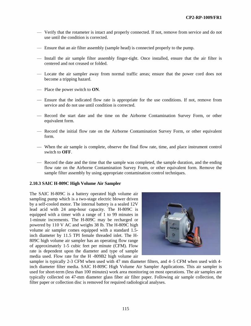
CP2-RP-1009/FR1
115
— Verify that the rotameter is intact and properly connected. If not, remove from service and do not
use until the condition is corrected.
— Ensure that an air filter assembly (sample head) is connected properly to the pump.
— Install the air sample filter assembly finger-tight. Once installed, ensure that the air filter is
centered and not creased or folded.
— Locate the air sampler away from normal traffic areas; ensure that the power cord does not
become a tripping hazard.
— Place the power switch to ON.
— Ensure that the indicated flow rate is appropriate for the use conditions. If not, remove from
service and do not use until condition is corrected.
— Record the start date and the time on the Airborne Contamination Survey Form, or other
equivalent form.
— Record the initial flow rate on the Airborne Contamination Survey Form, or other equivalent
form.
— When the air sample is complete, observe the final flow rate, time, and place instrument control
switch to OFF.
— Record the date and the time that the sample was completed, the sample duration, and the ending
flow rate on the Airborne Contamination Survey Form, or other equivalent form. Remove the
sample filter assembly by using appropriate contamination control techniques.
2.10.3 SAIC H-809C High Volume Air Sampler
The SAIC H-809C is a battery operated high volume air
sampling pump which is a two-stage electric blower driven
by a self-cooled motor. The internal battery is a sealed 12V
lead acid with 24 amp-hour capacity. The H-809C is
equipped with a timer with a range of 1 to 99 minutes in
1-minute increments. The H-809C may be recharged or
powered by 110 V AC and weighs 38 lb. The H-809C high
volume air sampler comes equipped with a standard 1.5-
inch diameter by 11.5 TPI female threaded inlet. The H-
809C high volume air sampler has an operating flow range
of approximately 1-5 cubic feet per minute (CFM). Flow
rate is dependent upon the diameter and type of sample
media used. Flow rate for the H -809B2 high volume air
sampler is typically 2-3 CFM when used with 47 mm diameter filters, and 4–5 CFM when used with 4-
inch diameter filter media. SAlC H-809C High Volume Air Sampler Applications. This air sampler is
used for short-term (less than 100 minutes) work area monitoring on most operations. The air samples are
typically collected on 47-mm diameter glass fiber air filter paper. Following air sample collection, the
filter paper or collection disc is removed for required radiological analyses.

CP2-RP-1009/FR1
116
Controls and Displays
— Air Flow Indicator—An individually calibrated rotameter marked from 1 to 5 CFM.
— On-Off—A double-throw On-Off switch.
— Digital switches—Recessed control on the top of the battery compartment to set the sample
duration.
— Calibrate/normal switch—This should be set to “NORMAL.” The calibrate setting is used only
during calibration.
Additional Features and Auxiliary Equipment—A variety of sample holders and cartridges are
available for use with the H-H-809C air sampler. A tripod is available. The sampler may be set to
collect a sample until a desired total volume or elapsed time has been reached. These parameters are
set during calibration.
Limitations and Precautions
— Fire(s) or explosion(s) can occur if this instrument is operated in explosive or combustible
environment(s).
— Electrical shock or equipment damage can occur if this instrument and the electrical cord are wet
during operation, or if the electrical cord is not properly grounded.
— The motor can become very hot when operated for longer than one hour. Take appropriate
precautions when handling.
— Use appropriate contamination control techniques when handling potentially contaminated filters
or filter holders.
— Care must be exercised to avoid contaminating the filter paper during sample start up, operation,
and filter paper removal. Use clean tweezers to handle the filter; keep the filter in a clean holder
before and after sample collection.
— Internal surfaces of the motor may become contaminated.
— Dust loading on sample filter may occur in a short time when operating in areas where
particulates are suspended (near grinding or similar operations). Air sample time/volume should
be kept to a minimum in these instances.
— The H-809C is not intended for outdoor use during inclement weather.
— The battery should be charged when the temperature is between 50°F and 1220°F. The
operational temperature range is between -400°F and 1220°F.

CP2-RP-1009/FR1
117
Operation
— Perform a visual inspection of the H -809B2 and the electrical cord for physical damage.
— If damage is found, remove the instrument from service and do not use until condition is
corrected.
— Verify that the H -809 has a valid and legible calibration label. If not, remove from service and do
not use until condition is corrected.
— Ensure that an air filter assembly is properly connected to the inlet.
— Install the air sample filter assembly finger-tight. Once installed, ensure that the air filter is
centered and not creased or folded.
— Locate the air sampler away from normal traffic areas; ensure that the power cord does not
become a tripping hazard.
— Place the power switch to “ON” and press the “START” key.
— Ensure that the indicated flow rate is appropriate for the use conditions. If the appropriate flow
rate cannot be obtained, remove from service and do not use until condition is corrected.
— Record the start date and the time on the Airborne Contamination Survey Form, or other
equivalent form.
— Record the initial flow rate on the Airborne Contamination Survey Form, or other equivalent
form.
— When the air sample is complete, observe the final flow rate and time and place instrument
control switch to “OFF.”
— Record the date and the time that the sample was completed, the sample duration, and the ending
flow rate on the Airborne Contamination Survey Form, or other equivalent form. Remove the
sample collection assembly by using appropriate contamination control techniques.
2.11 CONTINUOUS AIR MONITORS
Continuous air monitors (CAMs), used by D&R RADCON department, consist of air particulate
collectors that are monitored continuously by appropriate radiation detectors. CAMs for alpha emitters
have solid state detectors with alpha spectrometry to minimize response to naturally occurring short half-
lived radon and thoron daughters. CAMs for beta (gamma) emitters have shielded thin window G-M
tubes that operate in the gross beta count rate mode.
CAMs are required where there is a potential for an airborne release that could result in exposure to
≥ 40 DAC-Hr/yr. CAMs similarly are required to mitigate the consequences of potentially significant
accidental releases. The CAMs must be capable of detecting and alarming at concentrations of one DAC
when averaged over an eight-hour period (i.e., 8 DAC-hr.).
CAMs are used to monitor locations between workers and the potential point of release(s) and or

CP2-RP-1009/FR1
118
downwind of those points. Alarm levels are set as low as practicable with avoidance of excessive false
alarms (i.e., > 1/qtr).
Monitoring periods are usually for a work that might be equivalent to an 8-hour workday. Filters or
collection media are replaced at that time. Because of the adverse effect of particle loading on monitoring,
filters will be used no longer than 72 hours (excluding weekends).
CAMs must be checked daily to ensure proper operation including indication of a non-zero background,
and verification of the audible and visible alarm setting.
The applicable DAC will be provided with the RWP or work authorization documents. The applicable
DAC may be based upon the most restrictive radionuclide form or otherwise be derived through a
weighted ratio among the various radionuclide forms present. An example of the latter basis would be the
use of the beta DAC for Type S thorium-234 (9 E-08 μCi/ml).
2.11.1 Eberline Alpha-6A and 6A-1 Particulate Air Monitors
The Eberline ALPHA-6A and 6A-1 Particulate
Air Monitors are semiportable instruments for
detection and measurement of airborne alpha-
emitting particulates.
The Eberline ALPHA-6A and 6A-1 Particulate
Air Monitors both utilize a 256-channel spectral
analyzer, two microprocessors, LCD display,
keypad, and mass flow sensor. The detector
electronics and spectral analysis capability allow
for live-time thoron and radon discrimination.
These monitors require standard 110-volt AC
power for operation. Three lithium coin-cell
batteries provide backup battery power for
historical data retention and operation of the real-time clock. Both monitors typically are used with an
external RAP-1, or equivalent, low-volume regulated air sample pump that draws a sample of air through
an in-line Millipore SM (5 micron pore size).
Forty-seven mm diameter particulate membrane filter at a rate of 25–30 lpm. These monitors also may be
equipped with an optional 25-mm diameter filter holder. The ALPHA-6A/6A-1 can be equipped with an
in-line sampling tube for remote sampling evolutions.
The ALPHA-6A is equipped with a silicon diffused junction type semi-conductor solid-state detector,
with an area of 490 mm2. The detector is coated with aluminum to reduce light sensitivity. The
ALPHA-6A electronics system includes alarm circuitry, multichannel analyzer (MCA), preamplifier,
amplifier, and low voltage power supply.
The instrument display will indicate spectral or history data in graphical form or in a simulated strip chart
form. Indications of monitor status, date, time, and airflow rate are also provided on the LCD display. A
mass airflow measurement system continuously measures flow in the range of 15–60 lpm.
Operation of the keypad provides for spectrum display, cursor movement, region of interest (ROI)
selection and ROI viewing, and allows for selection of various menus and commands for testing and
calibration of the monitor. The detector (normal window) alpha radiation response is approximately 17%

CP2-RP-1009/FR1
119
for Pu-239 using the standard 47-mm diameter, filter holder.
This instrument is operated with an alarm setting; an alarm strobe light and bell are activated when the
alarm setting is reached. The aural and visual alarm indicators are provided on the top and side panels.
The power ON/OFF switch, connections for the air sample, pump intake, AC power supply. RS-232 serial
ports are provided on the rear panel for a printer and remote sampling evolution system communication.
Applications—The Eberline ALPHA-6A and 6A-1 Particulate Air Monitors maybe used to monitor
concentrations of airborne radioactivity at most operations. It may be used to monitor room air or
samples can be withdrawn from stacks or other specific atmospheres and transported by hose to the
instrument location. For these types of sample evolutions, the in-line sample/detector head can be
separated by up to 1,000 ft from the base unit, and located near the source of air being monitored.
Controls and Displays
— Display—The ALPHA-6A LCD display
presents a series of menus and viewing
options for the operator to perform a
variety of tasks.
— Message—This yellow lamp, located on
the left side of the front panel, will
illuminate when any alarm condition
occurs.
— Power On-Off—The ON-OFF switch is
located on the rear panel of the ALPHA-
6A.
— Power—This green lamp, located directly below the yellow MESSAGE lamp, indicates when the
power is turned on to the instrument.
Normal Status
— Menu—Depress this key to view/print history files, view/print monitor status, set alarm
parameters, set user constants, stop, start, and reset counters; set date, time, and serial port
protocol and enter/edit the access code.
— View—Depress this key to view and select ROI spectral displays, select strip chart displays and
alarm set point values.
— ▬►Depress this key to move the display cursor in the desired direction, as is indicated on the
keypad.
— Ch[ ]—Depress this key, followed by the desired channel number, to select a desired channel.
— Enter—Depress this key to prompt the instrument to perform a selected operation.
— Print—Depress this key to print the current displayed information, a selected ROI, data file,
monitor status, or historical operation information.

CP2-RP-1009/FR1
120
Alarms
Hardware Failures
— Hardware failures are the highest priority alarm indications. This type of alarm is not user
repairable. The type of hardware failure is indicated on the “Status” line of the display.
— Clk Fail—Clock failure indication. Failure is cleared through “System Setup Menu.” Access
code is required.
— P2 Fail—Indicates that the detector processor (P2) is not responding to the main processor.
— Lo Counts—Indicates that the detector processor has not received any counts from the detector
for at least two minutes.
User Alarms
User alarms are checked after hardware failures. Some alarms are indicated by the bell in addition to
the beeper and “Message” light. The bell and beeper can be silenced by pressing any key on the
keypad. User alarms are indicated on the “Status” line on the LCD display.
— Flow Fail—Indicated when there is a loss of vacuum.
— Noise AC—Indicated when power line noise or other external event has occurred that affects the
instrument electronics.
— Fast Alarm—Due to activity in the ROI, Bell is activated. The bell is located on the top of side
of the instrument.
— SLOW ALARM—Initial alarm due to increasing counts in the ROI.
— Flow Out of Limits—Indicates that the flow rate is either < 0.8 or > 1.2 CFM.
— Concern—Indicates that the calculated uranium concentration is greater than the set
concentration limit.
Warnings
Warnings are hardware-related conditions that include the following:
— Filter Door Open—Indicates that the filter door is not closed completely. The monitor will not
count until the door is closed completely.
— P2 Counters Halted—Indicates that the counters have halted. Counters are stopped and reset
whenever the filter door is opened.
— Low Battery—Indicates that the memory battery needs replacement.
Warnings are indicated by the message light and beeper. Check the “Status” line on the display for
alarm type.

CP2-RP-1009/FR1
121
Additional Features and Auxiliary Equipment—There are no additional features for the Eberline
ALPHA-6A and 6A-1 Particulate Air Monitors. The ALPHA-6A requires the use of a regulated air
sample pump. The pump suction hose is connected to the airline connection on the rear panel of the
ALPHA-6A.
Limitations and Precautions
— All calibration and operation parameters are defined during calibration and shall not be changed
unless approved by the radiation protection manager (RPM), or designee.
— The ALPHA-6A may alarm while performing various steps of this procedure; when this happens,
press any key on the keypad to silence the alarm.
— The first count factor is determine by the instrumentation group and should not be changed,
unless approved by the RPM, or designee.
— Fire(s) or explosion(s) can occur if this instrument is operated in explosive or combustible
environment(s).
— Electrical shock or equipment damage can occur if this instrument and the electrical cord are wet
during operation, or if the electrical cord is not properly grounded.
— Use appropriate contamination control techniques when handling potentially contaminated filters
or filter holders.
— Care must be exercised to avoid contaminating the filter paper during instrument start-up,
operation, and filter paper change-outs. Use clean tweezers to handle the filter; keep the filter in a
clean holder before and after sample collection.
— Filter paper should be changed at least daily. Under dusty conditions, the filter paper may need to
be changed more frequently.
— Internal surfaces of the instrument may become contaminated.
— The ALPHA-6A is not intended for outdoor use during inclement weather.
Operation
— Perform a visual inspection of the ALPHA-6A and the electrical cord for physical damage. If
damage is found, remove the instrument from service and do not use until the condition is
corrected.
— Confirm that the ALPHA-6A and the regulated air sample pump have a current and legible
calibration label. If not, remove from service and do not use until the condition is corrected.
Set-up
(1) Plug the power cord into a standard 110-volt AC outlet.
(2) Ensure that the POWER ON/OFF switch is turned OFF.

CP2-RP-1009/FR1
122
(3) Ensure that the air sample pump is connected to the ALPHA-6A.
(4) Depress the push button switch and open the filter door.
(5) Place the filter (collection side up, facing the detector) onto the filter holder, insert the filter
holding ring, and close the door until it locks into place.
(6) Turn the POWER ON-OFF and sample pump ON/OFF switches to the ON positions.
(7) Record the date, time and airflow rate indicated on the rotameter.
Filter Change-Out
NOTE: “Concern” alarm could be displayed for up to 30 minutes after filter change. The instruments
still will alarm during period, based on the cpm limit set for U-233 fast and slow alarms.
(1) To verify an alarm, which occurs while the instrument is updating its calculated concentration,
visually inspect the U-233 spectrum in ROI 1 to determine if any counts have been registered.
(2) Check and note flow rate on sample envelope (flow off).
(3) Turn pump off, and note date and time on sample envelope (date and time off).
(4) Press any key to acknowledge the alarm.
(5) Open the filter holder door.
(6) Remove the filter holder ring and the filter.
(7) Place the filter in the envelope.
(8) Place a new filter onto the filter backing.
(9) Place the filter holder ring onto the filter.
(10) Close the filter holder door, and tighten the lock knob until it is just snug. “DOOR OPEN”
status should clear.
(11) Turn pump on and note date and time that filter was started on sample envelope.
(12) Record the present flow rate on sample envelope (should be 1.0 ± 20%).
NOTE: All counters are reset after the filter holder door is closed.
(13) If first count factor is desired, count sample within one hour.
Routine Performance Test
NOTE: Routine performance test should be performed at least monthly while instrument is in
operation.
NOTE: Routine performance tests shall only be performed when the status line indicates “Normal.”

CP2-RP-1009/FR1
123
Conduct an alarm test by the following steps:
(1) Record date, time, and airflow on sample envelope under “off.”
(2) Turn the pump off.
(3) Open the filter holder door.
(4) Remove the filter and process.
(5) Apply the check source to the detector, then either close the detector door, or defeat the door
switch to allow the detector to start counting.
(6) Allow approximately 5-seconds for the alarm bell to sound, then press any key to acknowledge
the alarm.
(7) Remove the source.
(8) Place a new filter into the housing.
(9) Place the filter holder ring onto the filter.
(10) Close the door and tighten the lock knob until it is just snug. Allow approximately 5-seconds
for the “DOOR OPEN” status to be cleared from the display.
Performing Functional Check
NOTE: Functional check should be performed at least weekly while instrument is in operation.
(1) Verify that the instrument is turned on and the POWER indicator is lit.
(2) Inspect the instrument for any visible damage that could impair operation.
(3) Verify that the status line on the display indicates “Normal.”
NOTE: Functional checks shall only be performed when the status line indicates “Normal,” before
changing the filter, and with only normal radon background buildup on the filter. This ensures that the
filter has sufficient PO-214 (Ra/C) activity (4000 cts in the peak channel) for proper identification of
the PO-214 peak.
(4) Press the “VIEW” key followed by “0” to switch to the full spectrum display.
(5) Press the “CH[ ]” channel key.
NOTE: Pressing number keys after “CH[ ]” will move the cursor to the entered number channel.
(6) Enter “170.”
(7) Press “ENTER.”
(8) Press the right arrow key to move the cursor to the peak.

CP2-RP-1009/FR1
124
(9) Observe the counts per channel display (lower right “Counts” display) to verify that the peak
from PO-214 is within the acceptable channel range 9174-180) with the optimum peak between
channels 177 and 179.
(10) If the peak is outside the acceptable range after changing a new filter.
(11) Document functional Check results.
(12) Turn the pump on, and return the instrument to service.
2.12 SAMPLER CALIBRATORS AND AUXILIARY EQUIPMENT
The calibrators used here measure the volume flow rate and do not depend on air mass or thermal
properties as with some other calibration systems. The lowest flow rate calibrations, for personal air
samplers, utilize displacement of a frictionless piston. This is similar in principle to timing displacement
of a soap film “bubble” in a graduated burette. The remainder of the calibrators measures the pressure
drop across a venturi. The size of the venturi varies with the range of flow rate to be calibrated.
These “smart” calibrators convert the flow rate with the volume adjusted to a temperature of 70°F and an
atmospheric pressure of 760-mm Hg. The variation in the calibrated flow rate and the actual flow rate
varies relative to the difference between the sampling location temperature and pressure. The volume of a
gas decreases with pressure and increases with temperature. There would have to be a very significant
change in temperature and pressure to warrant correction to the airborne concentration. For example, a
difference of 30°F would affect the flow rate by about 5%. A pressure difference of 1 inch (25.4 mm) Hg
would affect the flow rate by about 3%. The airborne concentration likely will be more affected by
positioning and by changing air flow patterns than by reasonably anticipated changes in temperature and
pressure.
2.12.1 Bios Dry Cal DC-1 Flow Calibrator
The Bios Dry Cal DC-1 Flow Calibrator is a primary
standard used to calibrate flow rate of air sampling pumps
and other flow indicating/monitoring devices, such as
rotameters. It consists of two separate sections: a flow cell
and a base containing a computer and other electronics. It
is powered by an internal, rechargeable, lead-acid battery.
The general principle of this unit is that an air stream flows
into the cell moving a frictionless piston in a sealed
chamber. A precision encoder, attached to the piston,
breaks a collimated light beam, and a crystal timer
measures the time between breaks in the light beam. The
computer calculates the flow rate based on the distance
traveled, the dimensions of the chamber, and the time
elapsed. Measurements are repeated automatically and an
average computed to provide increased accuracy. After ten
repetitive measurements, the system automatically clears
and repeats the sequence. Accuracy is reported by the manufacturer to be ± 1% for higher flow rates
and/or multiple measurements.

CP2-RP-1009/FR1
125
Applications—The Bios Dry Cal DC-1 Flow Calibrator can be used with different measuring cells
for different flow ranges; however, the application in the D&R program is for calibration of personal
air samplers (lapel samplers) having a flow rate that typically does not exceed 10 lpm.
Controls and Displays
— Charge Indicator—A red light on the front panel is illuminated when the charger is
PROPERLY CONNECTED.
— Display—An LCD indicates operating status, provides direction for operation, and reads out flow
measurements, average flow of repetitive determinations, and number of determinations to
calculate average flow. The system senses the measuring cell in use and automatically selects
proper ranges and measurement units.
— Mode Switch—Depressed to initiate instrument setup.
— Off/On Switch—This switch activates the unit. Power is provided by a rechargeable lead-acid
battery. If the battery requires charging, a “BAT” indication is displayed.
— Read Switch—Depressed to perform flow rate measurement.
Additional Features and Auxiliary Equipment—The Bios Dry Cal DC-1 Flow Calibrator is
equipped with a printer that connects to the rear of the DC-1 case; each flow measurement result is
printed along with the average and number of determinations in the average. Other measuring
chambers, extending the range of this calibrator to 50 lpm, are available options. A damper assembly
is provided to insert between the load and the sampler to suppress vibrations. Tubing and hose
connectors are required to attach samplers and other devices to the calibrator.
Limitations and Precautions—Certain personal samplers, rotameters, and manometers may exhibit
pulsations and vibrations at low flow. This condition will cause the calibrator to vibrate during
measurements and may result in erroneous measurements. An isolating load, as described in the
manufacturer’s literature, should be used to ensure accurate measurements and prevent possible
damage to the equipment.
Operation
— Confirm that the Bios Dry Cal DC-1 Flow Calibrator has a current and legible calibration label; if
not, remove from service and do not use until the condition is corrected.
— Ensure that the daily instrument performance tests have been satisfactorily completed (all
readings are within the defined acceptable range) and documented on a daily test sheet or perform
those tests in accordance with established procedure, if required.
Self-Test
— Turn the unit off and invert it so that the piston falls to the inner tube.
— Place the unit on a flat surface leaning it backwards with the rear of the base and the top of the
cell touching the surface. The piston should remain at the top of the inner tube.

CP2-RP-1009/FR1
126
— Place the test plug over one of the air connection nipples.
— Turn the unit ON while depressing the “Mode” button. The display will indicate “Leak Test
Push Read.”
— Place the unit upright and press the “Read” button. The unit will proceed to test itself for leakage
of the piston valve. If leakage exceeds the accepted limits, the display will indicate
“Maintenance Read Push Read.” If leakage is acceptable, the display will indicate “Cell OK
Push Read.”
— Repeat the test for the other air connection nipple.
— When both sides are tested satisfactorily, push the “Read” button and proceed to perform flow
measurements.
— If tests are not satisfactory, remove the unit from service until the problems can be rectified.
Flow Readings
— Ensure that the expected flow rate is within the recommended range of the measuring cell.
— Connect the unit to the device to be calibrated with flexible tubing. Use the right-hand connector
for negative pressure measurement and the left-hand connector for positive pressure.
2.12.2 Bios Defender 510 and Defender 520 Flow Calibrator
The Bios Defender Flow Calibrator is a primary standard used to
calibrate flow rate of air sampling pumps and other flow
indicating/monitoring devices, such as rotameters. It consists of two
separate sections: a flow cell and a base containing a computer and
other electronics. It is powered by an internal, rechargeable, lead-acid
battery. The general principle of this unit is that an air stream flows
into the cell moving a frictionless piston in a sealed chamber. A
precision encoder, attached to the piston, breaks a collimated light
beam, and a crystal timer measures the time between breaks in the
light beam. The computer calculates the flow rate based on the
distance traveled, the dimensions of the chamber, and the time
elapsed. Measurements are repeated automatically and an average computed to provide increased
accuracy. After 10 repetitive measurements, the system automatically clears and repeats the sequence.
Accuracy is reported by the manufacturer to be ± 1% for higher flow rates and/or multiple measurements.
Applications—The Bios Defender Flow Calibrator can be used with different measuring cells for
different flow ranges; however, this application is for calibration of personal air samplers (lapel
samplers) having a flow rate that typically does not exceed 10 lpm.
Controls and Displays
— Charge Indicator—A red light on the front panel is illuminated when the charger is
PROPERLY CONNECTED.

CP2-RP-1009/FR1
127
— Display—An LCD indicates operating status, provides direction for operation, and reads out flow
measurements, average flow of repetitive determinations, and number of determinations to
calculate average flow. The system senses the measuring cell in use and automatically selects
proper ranges and measurement units.
— Mode Switch—Depressed to initiate instrument setup.
— Off/On Switch—This switch activates the unit. Power is provided by a rechargeable lead-acid
battery. If the battery requires charging, a “BAT” indication is displayed.
— Read Switch—Depressed to perform flow rate measurement.
Additional Features and Auxiliary Equipment—The Bios Defender Flow Calibrator is equipped
with a printer that connects to the rear of the Defender case; each flow measurement result is printed
along with the average and number of determinations in the average. Other measuring chambers,
extending the range of this calibrator to 50 lpm, are available options. A damper assembly is provided
to insert between the load and the sampler to suppress vibrations. Tubing and hose connectors are
required to attach samplers and other devices to the calibrator.
Limitations and Precautions—Certain personal samplers, rotameters, and manometers may exhibit
pulsations and vibrations at low flow. This condition will cause the calibrator to vibrate during
measurements and may result in erroneous measurements. An isolating load, as described in the
manufacturer’s literature, should be used to ensure accurate measurements and prevent possible
damage to the equipment.
Operation
— Confirm that the Bios Defender Flow Calibrator has a current and legible calibration label; if not,
remove from service and do not use until the condition is corrected.
— Ensure that the daily instrument performance tests have been satisfactorily completed (all
readings are within the defined acceptable range) and documented on a daily test sheet or perform
those tests in accordance with established procedure, if required.
Self-Test
— Turn the unit off and invert it so that the piston falls to the inner tube.
— Place the unit on a flat surface leaning it backwards with the rear of the base and the top of the
cell touching the surface. The piston should remain at the top of the inner tube.
— Place the test plug over one of the air connection nipples.
— Turn the unit ON while depressing the “Mode” button. The display will indicate “Leak Test
Push Read.”
— Place the unit upright and press the “Read” button. The unit will proceed to test itself for leakage
of the piston valve. If leakage exceeds the accepted limits, the display will indicate
“Maintenance Read Push Read.” If leakage is acceptable, the display will indicate “Cell OK
Push Read.”

CP2-RP-1009/FR1
128
— Repeat the test for the other air connection nipple.
— When both sides are tested satisfactorily, push the “Read” button and proceed to perform flow
measurements.
— If tests are not satisfactory, remove the unit from service until the problems can be rectified.
Flow Readings
— Ensure that the expected flow rate is within the recommended range of the measuring cell.
— Connect the unit to the device to be calibrated with flexible tubing. Use the right-hand connector
for negative pressure measurement and the left-hand connector for positive pressure.
2.12.3 F&J Digital Venturi Airflow Calibrator
The F&J Digital Venturi Airflow
Calibrator is a microprocessor-
controlled instrument used to calibrate
flow rate of air sampling pumps and
other flow indicating/monitoring
devices.
This general calibrator type is
available in eight models for
applications to different flow ranges;
four models of this device—Model
D-802, Model D-812, Model D-814,
and Model D-550 are used for
calibration of air sampling
instruments. The instrument corrects
flows to standard temperature (70°F)
and pressure (760 mm Hg) conditions.
The F&J Digital Venturi Airflow
Calibrator design allows calibrated flow rate that is independent of pressure drop across the equipment
being calibrated. The calibrators are AC-powered, but some models have provisions for battery power.
The general principle of this type unit is that a fluid (air) stream passing through a constriction (venturi)
creates a pressure difference that is related to the density of the fluid and its velocity. By knowing the
cross-sectional area of the Venturi, the density of air, and the temperature and atmospheric pressure, the
flow rate at standard temperature and pressure can be calculated. The calibrator has a digital LCD, which
provides readout of corrected flow rate, flow rate units, and ambient temperature and barometric pressure.
Flow rate accuracy is reported by the manufacturer to be ± 2%.
Applications—The Model D-802 calibrator has a flow range of 6–56 lpm (0.2-2 CFM) and is used
for calibrating the flow rate of low-volume air samplers, such as the HV-30, PQ-100, MRV-0523C,
and HD-29A; as well as CAMs such as the Alpha Sentry or Alpha-6A. The Model D-812 calibrator
has a flow range of 14–115 lpm (0.5–4 CFM) and is used for calibrating airflow rate of low-volume
air samplers, such as the LV-1, AVS-28A, HD-29A, or comparable instruments. The Model D-814
calibrator has a flow range of 28–400 lpm (1–14 CFM) and is used for calibrating airflow rate of
midrange air samplers, such as the HV-1. The Model D-550 calibrator has a flow range of

CP2-RP-1009/FR1
129
140–1400 lpm (5–50 CFM) and is used for calibrating airflow rate of most high-volume air samplers,
such as the Staplex TFIA and comparable equipment.
Controls and Displays
— Display—The parameter selected is shown on the LCD display, which provides a four-digit
value.
— Off-On Switch—This switch, located on the blower left of the front panel, activates the unit.
— Select Button—Pressing this button selects parameter and units to be shown on the LCD display. The selected parameter is indicated by a green LED light beside the parameter.
Additional Features and Auxiliary Equipment—Tubing, adapters, and hose connectors are
required to attach samplers and other devices to the calibrator.
Limitations and Precautions—When beginning operation, warm up the unit for at least 10 minutes to allow electronic components to stabilize. Because different models are available, confirm that the model selected has the appropriate flow rate range for the sampler of device being calibrated. Dust, oil vapors, fumes, and corrosive atmospheres will damage the venturi unit and sensors; avoid using or storing the calibrator in such environments.
Operation — Confirm that the F&J Digital Venturi Airflow Calibrator has a current and legible calibration
label; if not, remove from service and do not use until the condition is corrected.
— Ensure that the daily instrument performance tests have been satisfactorily completed (all readings are within the defined acceptable range) and documented on a daily test sheet or perform those tests in accordance with D&R procedure, if required.
— Turn the F&J Digital Venturi Airflow Calibrator on by flipping the OFF-ON switch to the ON position; verify that an LED light and the LCD display are illuminated.
— The LCD display will default to a flow rate of 0.00 CFM (assuming there is no flow through the unit).
— Press the SELECT button to step through the various parameters confirming that each of the LED indicators is working.
— Connect the F&J Digital Venturi Airflow Calibrator to the inlet of the sampler or device to be calibrated. Always insert a load, such as a filter assembly and filter, typical of that to be used with the air sampler between the sampler and the calibrator. Ensure that the expected flow rate is within the recommended range of the measuring cell.
— Turn the air-sampling device on.
— Select the flow parameter of interest using the SELECT button and record the data collected.
— When completed with measurements, turn the sampling pump OFF and then turn the calibrator OFF.

CP2-RP-1009/FR1
130
2.12.4 Hi-Q HFC-50C Calibrator
The Hi-Q HFC-50C Airflow Calibrator is used to
calibrate flow rate of air sampling pumps and
other flow indicating/monitoring devices. The
instrument direct meter readout will indicate flows
at standard temperature (70°F) and pressure (760
mm Hg) conditions, requiring correction factor
application for the actual sample collection
environment. The calibrator design allows
calibrated flow rate that is independent of pressure
drop across the equipment being calibrated. The
general principle of this type unit is that a fluid
(air) stream passing through a constriction
(venturi) creates a pressure difference that is
related to the density of the fluid and its velocity.
By knowing the cross-sectional area of the venturi,
the density of air, and the temperature and atmospheric pressure, the flow rate at standard temperature and
pressure can be calculated. The calibrator has an analog meter display that provides readout of flow rate
in units of SCFM.
Applications—The Model HFC-50C calibrator has a flow range of 300–1,400 lpm (10–50 CFM) and
is used for calibrating airflow rate of high-volume air samplers, such as the Staplex TFIA, SAIC
H-810, or comparable instruments.
Controls and Displays
— Display—The direct reading flow rate is an analog meter.
Additional Features and Auxiliary Equipment—Tubing, adapters, and hose connectors are
required to attach samplers and other devices to the calibrator.
Limitations and Precautions—Dust, oil vapors, fumes, and corrosive atmospheres will damage the
venturi unit and sensors; avoid using or storing the calibrator in such environments.
Operation
— Confirm that the Hi-Q HFC-50C Venturi Airflow Calibrator has a current and legible calibration
label; if not, remove from service and do not use until the condition is corrected.
— Ensure that the daily instrument performance tests have been satisfactorily completed (all
readings are within the defined acceptable range) and documented on a daily test sheet or perform
those tests in accordance with established procedure.
— Connect the HFC-50C calibrator to the inlet of the sampler or device to be calibrated. Always
insert a load, such as a filter assembly and filter, typical of that to be used with the air sample
between the sampler and the calibrator. Ensure that the expected flow rate is within the
recommended range of the measuring cell.
— Turn the air-sampling device on.

CP2-RP-1009/FR1
131
— Record the data collected.
— When completed with measurements, turn the sampling pump off and then disconnect it from the
calibrator.
2.12.5 Mini-Buck Primary Flow Calibrator
The Buck M-5 and M-30 Flow Calibrators are NIST traceable
primary standards with accuracy of ± 0.5% of reading. A
microprocessor measures the time for a frictionless soap bubble
film in a cylinder of known diameter to travel from the first
sensor to the second sensor and calculates the flow rate. The M-5
and M-30 differ only in flow rate ranges: the Model M-5
functions from 1 to 6,000 cc/min and the Model M-30 functions
from 100 cc/min to 30 lpm. The flow cell, when properly filled
with soap solution, is spill proof. The calibrator contains a
rechargeable battery with an 8-hour use rating.
Applications—The mini-buck flow calibrator is suitable for
verifying rotameters, PAM samplers, and low volume samplers. The flow
cell may be connected in-line or to atmosphere at either the inlet or outlet. If connected in-line
(between a filter holder and a sampler), manual corrections are needed to calculate the flow rate at
normal pressure.
Controls and Displays
— Off/On Switches—The ON switch activates the unit. It is also used to reset the display. Power is
provided by a rechargeable Ni-Cd battery. If the battery requires charging, a red “Low Battery”
light will be illuminated. The OFF button turns off the calibrator. If connected to the AC adapter,
the calibrator will charge the internal battery even if switched off.
— Display—A LCD display indicates 0000’s with no decimal place when first turned on. If no
measurements are performed within 7 minutes from turn on, the unit will turn itself off. A series
of “----” are displayed during a test. During sequential tests, the previous reading and the current
reading are averaged – if the current reading differs from the previous reading by more than 5%,
the display will flash a series of EEEE’s four times and then display the actual last test result. The
next flow reading will start this averaging technique again. If individual test results are desired,
then the “ON” button may be pushed to reset the unit between tests. The flashing numbers on the
display continue for three seconds after a test. The purpose is to permit sufficient time for the
soap to return to the bottom.
— Plunger—Used to initiate bubbles for each test.
Additional Features and Auxiliary Equipment—Tubing, in-line filter holders, filters, and hose
connectors are required to attach samplers and other devices to the calibrator. Buck Calibrator Soap
should be used to fill the flow cell properly. The unit should be charged with the AC adapter prior to
first use. A full recharge takes about 16 hours.
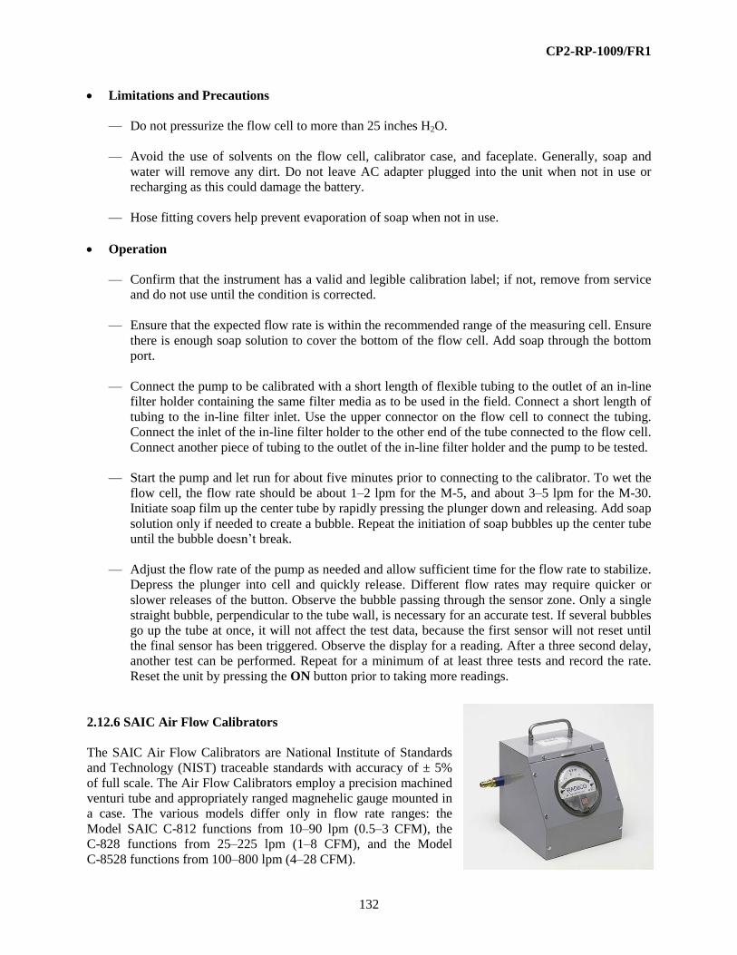
CP2-RP-1009/FR1
132
Limitations and Precautions
— Do not pressurize the flow cell to more than 25 inches H2O.
— Avoid the use of solvents on the flow cell, calibrator case, and faceplate. Generally, soap and
water will remove any dirt. Do not leave AC adapter plugged into the unit when not in use or
recharging as this could damage the battery.
— Hose fitting covers help prevent evaporation of soap when not in use.
Operation
— Confirm that the instrument has a valid and legible calibration label; if not, remove from service
and do not use until the condition is corrected.
— Ensure that the expected flow rate is within the recommended range of the measuring cell. Ensure
there is enough soap solution to cover the bottom of the flow cell. Add soap through the bottom
port.
— Connect the pump to be calibrated with a short length of flexible tubing to the outlet of an in-line
filter holder containing the same filter media as to be used in the field. Connect a short length of
tubing to the in-line filter inlet. Use the upper connector on the flow cell to connect the tubing.
Connect the inlet of the in-line filter holder to the other end of the tube connected to the flow cell.
Connect another piece of tubing to the outlet of the in-line filter holder and the pump to be tested.
— Start the pump and let run for about five minutes prior to connecting to the calibrator. To wet the
flow cell, the flow rate should be about 1–2 lpm for the M-5, and about 3–5 lpm for the M-30.
Initiate soap film up the center tube by rapidly pressing the plunger down and releasing. Add soap
solution only if needed to create a bubble. Repeat the initiation of soap bubbles up the center tube
until the bubble doesn’t break.
— Adjust the flow rate of the pump as needed and allow sufficient time for the flow rate to stabilize.
Depress the plunger into cell and quickly release. Different flow rates may require quicker or
slower releases of the button. Observe the bubble passing through the sensor zone. Only a single
straight bubble, perpendicular to the tube wall, is necessary for an accurate test. If several bubbles
go up the tube at once, it will not affect the test data, because the first sensor will not reset until
the final sensor has been triggered. Observe the display for a reading. After a three second delay,
another test can be performed. Repeat for a minimum of at least three tests and record the rate.
Reset the unit by pressing the ON button prior to taking more readings.
2.12.6 SAIC Air Flow Calibrators
The SAIC Air Flow Calibrators are National Institute of Standards
and Technology (NIST) traceable standards with accuracy of ± 5%
of full scale. The Air Flow Calibrators employ a precision machined
venturi tube and appropriately ranged magnehelic gauge mounted in
a case. The various models differ only in flow rate ranges: the
Model SAIC C-812 functions from 10–90 lpm (0.5–3 CFM), the
C-828 functions from 25–225 lpm (1–8 CFM), and the Model
C-8528 functions from 100–800 lpm (4–28 CFM).

CP2-RP-1009/FR1
133
Applications—The Air Flow Calibrator is suitable for verifying rotameters, low volume samplers,
and some high volume samplers. The calibrator may be connected in-line or to atmosphere at either
the inlet or outlet. If connected in-line (between a filter holder and a sampler), manual corrections are
needed to calculate the flow rate at normal pressure.
Controls and Displays
— Display—A 5-inch diameter magnehelic gauge is calibrated to read directly lpm and CFM by the
manufacturer.
Additional Features and Auxiliary Equipment—Tubing, in-line filter holders, filters, and hose
connectors are required to attach samplers and other devices to the calibrator.
Limitations and Precautions
— Do not pressurize the calibrator to more than 15 psig or subject the venturi to a vacuum of more
than 20-inch Hg or the magnehelic gauge may be damaged.
— The Air Flow Calibrator is calibrated at standard conditions of 70°F and 29.92-inch Hg. The inlet
should be left open to atmosphere; otherwise, corrections must be made to the flow rate based on
the actual pressure at the venture inlet.
Operation
— Confirm that the instrument has a valid and legible calibration label; if not, remove from service
and do not use until the condition is corrected.
— Ensure that the expected flow rate is within the recommended range of the air flow meter. The
upper 80% of the scale should be used since the uncertainty of calibration is greater than 20% of
reading over the lower 20% of the scale.
— Connect the pump to be calibrated with a short length of flexible tubing to the outlet of an in-line
filter holder containing the same filter media as to be used in the field. Connect a short length of
tubing to the in-line filter inlet. Connect the inlet of the in-line filter holder to the other end of the
tube connected to the airflow calibrator. Connect another piece of tubing to the outlet of the in-
line filter holder and the pump to be tested.
— Adjust the flow rate of the pump, as needed, and allow sufficient time for the flow rate to
stabilize. Observe the display for a reading. Use the mirrored arc to minimize parallax errors
when reading the scale.
2.13 LABORATORY INSTRUMENTATION
Proper radiological controls require the use of sensitive instruments to characterize field conditions
properly. Low background alpha and beta detectors are used to measure removable contamination levels
and determine airborne concentrations. Some of these instruments have specific applications such as
liquid scintillation counting for low energy beta emitters. Others, such as the Canberra EasySpec, allow

CP2-RP-1009/FR1
134
specific radionuclide identification. Regardless of the instrument, there are several important points for
effective application and information.
Exercise exquisite contamination control to prevent potential contamination of the instruments and to
prevent cross-contamination of samples. All samples and containers are to be field screened with portable
instruments to identify the nature and extent of contamination controls required. In most cases, this can be
accomplished in the field. In other cases, monitoring for contamination will be accomplished as the
samples arrive in the preparation area. The preparation area must be far enough from the instruments to
minimize the possibility for any potential contamination. Contamination levels that are not detectable by
survey instruments can have a dramatic effect on the results. For example, even minimal
cross-contamination of an air particulate filter can yield erroneously high results. Monitoring is important,
but careful handling is equally as important.
Simple and properly applied quality controls ensure good data. These range from sample identification
and data correlation to source, background, and built-in system checks. It is essential to implement these
measures carefully in every phase of sample conveyance, preparation, and analysis. In many cases, it is
difficult to recover the data after an anomaly is discovered.
Similar care must be exercised in recording data properly on the requisite forms and logs. All of the
information must be accurate in order to assure that the radiological conditions have been identified
properly and any related actions are taken.
2.13.1 Ludlum Model 2929 Alpha/Beta Scaler
The Ludlum Model 2929 Alpha/Beta Scaler is a portable alpha/beta-gamma dual channel scaler that
provides the electronic circuitry for simultaneous measurements for alpha and beta-gamma radiation
levels when connected to a Ludlum Model 43-10-1 alpha/beta-gamma scintillator. The Ludlum Model
2929 Alpha/Beta Scaler provides the electronics for alpha or beta-gamma radiation discrimination. It
typically is used for counting smears. The Ludlum Model 2929 Alpha/Beta Scaler also may be used for
counting other media provided the sample
geometry conforms to the 2-inch diameter
sample counting cavity. Typical efficiencies
for counting alpha and beta are
approximately 28% and 26%, respectively.
The Ludlum Model 2929 Alpha/Beta Scaler
is operated by 110-volt line power only.
The Ludlum Model 2929 Alpha/Beta Scaler
has an effective count range of 0–999,999
counts. A thumb-wheel allows adjustment for
selection of count time from 0–99 minutes. In
conjunction with the thumb-wheel, a 4-
position rotary switch is used for selection of
count time. The switch positions allow
multiplication of the number of minutes selected with the thumbwheel. The switch positions are x 0.1,
x 1, x 10, and EXT for manual extended timed counts. A toggle switch controls power to the instrument
(On-Off). Push buttons are provided for initiating a scaler Count and scaler count Hold. A 10-turn,
friction-locked potentiometer allows adjustment of operating high voltage. Two rotary knobs allow
adjustment of alpha and beta audio signal volume. An analog meter is provided for high voltage display.
Two LCDs are provided for alpha and beta counts. Red lights indicate when AC power is turned on and
when a count is in progress.

CP2-RP-1009/FR1
135
Two 15-pin connectors, Alpha Out and Beta Out, are provided on the instrument back panel for recorder,
printer, or software interface connections. A BNC-type connector also is provided on the instrument back
panel for a detector pulse amplifier connection.
Applications—The Ludlum Model 2929 Alpha/Beta Scaler is used to measure sample radioactivity
in units of cpm. It can be used to determine radioactivity levels, ranging from typical background
values to those expected in most operations. The Ludlum Model 2929 Alpha/Beta Scaler typically is
calibrated using Th-230 and Pu-239 (alpha) and Tc-99 and Sr-90 (beta). The Ludlum Model 2929
Alpha/Beta Scaler is suitable for the following types of survey samples:
— Equipment surface contamination
— Radiological area identification
— Radioactive material shipments
— Characterization
— Quantitative smear sample measurements
Controls and Displays
— On/Off—To turn the instrument power on, move the toggle switch to the ON position.
— HV—The operating voltage is indicated on the LCD display above the HV potentiometer in units
kV; the HV potentiometer should not be adjusted.
— Minutes—To select the count time, rotate the thumbwheel to the desired minutes; turn the rotary
switch to x 0.1, x 1, x 10, or EXT to multiply the minutes selected using the thumbwheel, or
perform manual extended time period count (EXT).
— Count—To begin a scaler-counting period, depress this push button. This push button is located
in the carrying handle.
— Hold—To temporarily suspend or freeze the collection of scaler counts, depress this push button.
To continue collection of counts, depress this push button.
— Alpha Vol—To adjust the alpha count audio signal, turn this knob.
— Beta-Gamma Vol—To adjust the beta-gamma count audio signal, turn this knob.
— Display—Operating high voltage is indicated on the LCD display above the HV potentiometer.
Scaler counts are indicated on the ALPHA COUNT and BETA-GAMMA COUNT LCD
displays. Both LCD scaler count ranges are 0–999,999 counts.
Additional Features and Auxiliary Equipment—A Model 264 printer may be connected to this
instrument; one printer is required for each channel (alpha and beta-gamma).
Limitations and Precautions—This instrument is designed for indoor use or in an environment
where temperature and humidity can be controlled.

CP2-RP-1009/FR1
136
Operation
— Determine the type(s) of radioactivity to be measured.
— Ensure that the Ludlum Model 2929 Alpha/Beta Scaler is located in a low background radiation
area.
— Confirm that the Ludlum Model 2929 Alpha/Beta Scaler has a current and legible calibration
label; if not, remove from service and do not use until the condition is corrected.
— Determine the radiological contamination levels of interest. Historical, job process, and other
work documents should provide information regarding radionuclides and types of contamination
expected. This information is available from the RCT supervisor and typically is provided on the
RWP for the survey(s) to be performed. This will assist in the proper selection of instrumentation.
— Ensure that daily instrument performance tests have been completed satisfactorily (all readings
are within the defined acceptable range) and documented on a daily test sheet or perform those
tests in accordance with D&R procedure.
— Turn the toggle switch from the OFF position to the ON position.
— The red light located above the ON-OFF toggle switch should illuminate.
— Ensure that the voltage indicated on the LCD display above the HV potentiometer is the same as
the HV identified on the calibration label; if not, remove from service and do not use until the
condition is corrected.
— Turn the ALPHA VOL and/or the BETA VOL knobs clockwise until clicks are audible, or turn
the knob(s) until the output of the audio signal(s) is acceptable.
— Select the desired count time by turning the MINUTES thumbwheel switch to indicate the
number of minutes; turn the rotary switch to indicate the appropriate count time multiplier for the
MINUTES selected (e.g., thumbwheel switch indicates 01 MINUTES and the rotary switch is on
the x 10 position = a 10-minute count time).
— Rotate the slide lever on the side of the detector drawer to the unlocked position and slide the
counting tray drawer open.
— Ensure that a clean planchet is provided in the detector drawer slide tray.
— Placing the sample to be counted in the detector drawer slide tray, close the slide tray and rotate
the slide lever on the detector drawer to the locked position.
— Depress the COUNT push button. The red light located between the COUNT and HOLD push
buttons will illuminate, indicating a count is in progress.
— When the count has been completed, the red light will turn off.
— Note the indicated values on the ALPHA COUNT and/or BETA-GAMMA COUNT LCD
displays.

CP2-RP-1009/FR1
137
— Rotate the slide lever on the side of the detector drawer to the unlocked position and slide the
counting tray drawer open.
— Remove the sample from the slide drawer tray.
— Close the slide tray and rotate the slide lever on the detector drawer to the locked position.
2.13.2 Ludlum Model 3030 Alpha/Beta Scaler
The Ludlum Model 3030 is a dual-channel counter designed for
simultaneous alpha and beta sample measurement. The built-in
dual ZnS/plastic scintillation detector features a shielded chamber
and stainless steel sample tray that can accept a maximum sample
size of 2" diameter. A pulse height analyzer is employed to provide
information to the two independent counters.
The Model 3030 is normally operated while connected to 115 V
AC. The Model 3030 also has an internal trickle-charged gel-cell
battery that can provide 8 hours of use. It has a built-in detector
high voltage power supply, adjustable count time periods, and has
a click-per-event audio with adjustable volume. The two
independent LCDs (liquid crystal displays) feature six 0.5-inches
tall digits, and are backlit for good visibility.
The instrument may be operated as a traditional scaler (counts per minute) and with a manually adjusted
high voltage. However, the instrument can also be enabled with advanced features. The 9-pin RS-232
connector on the back of the instrument allows the attachment to a computer or to a printer. Software is
provided to allow the setup of several enhancement parameters. The counts per minute (cpm) or
disintegrations per minute (dpm) modes can be enabled, allowing the count to be converted automatically
in real-time to cpm or dpm. Background radiation count can be subtracted out automatically in either
mode. Crosstalk correction, alpha or beta alarms, and time/date may also be set. Parameters are stored in
the Model 3030 in non-volatile memory; clock time/date is maintained with an internal lithium battery.
Another advanced feature, which may be enabled or disabled, is the QC (Quality Control) Check
function. When enabled, the user must perform measurements on known sources (and background) and
receive acceptable numbers for the instrument to be used that day. Twenty-four hours later, the QC LED
is turned on, indicating the need for another QC Check. This feature ensures that the instrument is tested
daily and that measurements are valid.
Specifications
— The Ludlum Model 3030 Alpha/Beta Scaler has an effective count range of 0 to 999,999 counts
or dpm.
— A rotary switch is used to select count times from 0.1, 0.5, 1, 2, 5, 10 minutes or a PC position
that selects the user-defined count time. User count time may be set from 0.1 to 546 minutes.
— Two 0.5-inch Backlit LCDs are provided for alpha and beta counts.
— Size: 10.75-inches tall, 7.125-inches wide, and 10-inches deep.

CP2-RP-1009/FR1
138
— Weight: 32 lb
— Typical Performance Efficiency (4 pi):
— Th-230 Alpha = greater than 30%
— Pu-239 Alpha = greater than 32%
— Tc-99 Beta = greater than 30%
— Pu-239 alpha crosstalk in beta channel less than 10%
— Beta crosstalk in alpha channel less than 1 %
— Beta background less than 50 cpm in 10 uR/h field
— Alpha background less than 3 cpm
Applications—The Ludlum Model 3030 Alpha/Beta Scaler is used to measure sample radioactivity
in units of counts per minute or (if enabled at setup) net activity in dpm. It can be used to determine
radioactivity levels, ranging from typical background values to those expected in most operations.
The Ludlum Model 3030 Alpha/Beta Scaler is typically calibrated using Th-230 and Pu-239 (alpha)
and Tc-99. The Ludlum Model 3030 Alpha/Beta Scaler is suitable for the following types of survey
samples:
— Equipment surface contamination
— Radiological area identification
— Radioactive material shipments
— Characterization
— Quantitative smear sample measurements
Controls and Displays
— ON - OFF—To turn the instrument power on, move the rocker switch to the ON position.
— COUNT TIME (MINUTES)—To select the count time, rotate the rotary switch to the
appropriate count time. The count times are 0.1, 0.5, 1, 2, 5, 10 or PC. PC is defined during
instrument setup.
— COUNT—To begin a scaler-counting period, depress this pushbutton.
— VOLUME—To adjust the audio signal, turn this knob.
— DISPLAY—Scaler counts are indicated on the ALPHA and BETA LCD displays. Both LCD
scaler count ranges are 0-999999 counts.
— QC—If enabled, this red LED will light 24 hours after the last QC check. A successful QC check
must be performed to extinguish the light.
— QC CHECK—Starts the QC check cycle.

CP2-RP-1009/FR1
139
— OL—This red LED illuminates when excess current has been detected. The instrument will not
count if an overload has been detected. This is usually from a light leak due to a mispositioned
tray or ripped detector window.
— CPM—This green LED lights when CPM mode has been selected. If this mode has been
selected, the count time is used to calculate the count rate in cpm.
— DPM—This green LED lights when DPM mode has been selected. If this mode has been
selected, the count time is used to calculate the count rate in dpm.
— αAL—This red LED lights when the alpha count exceeds the alpha alarm level established during
instrument setup.
— βAL—This red LED lights when the alpha count exceeds the alpha alarm level established during
instrument setup.
Additional Features and Auxiliary Equipment—A serial printer may be connected to this
instrument. A computer and the vendor-supplied software is required for calibration. Instrument
operation may also be performed through the computer interface.
Limitations and Precautions
— This instrument is designed for use indoors, or in an environment where temperature and
humidity can be controlled.
— Operation of this instrument is covered under two separate JPM's (Job Performance Measures).
Basic operation is included in the JPM for a Ludlum Model 2929 and advanced operation is
covered by a JPM specific for this instrument.
Operation
— Ensure that the Ludlum Model 3030 Alpha/Beta Scaler is located in a low background radiation
area.
— Confirm that the Ludlum Model 3030 Alpha/Beta Scaler has a current and legible calibration
label; if not, remove from service and do not use until condition is corrected.
— Ensure that the instrument is turned on and the daily instrument performance tests have been
satisfactorily completed (all readings are within the defined acceptable range) and documented on
a Daily Test Sheet or perform those tests in accordance with D&R procedure.
— Tum the VOLUME knob clockwise until clicks are audible, or tum the knob(s) until the output of
the audio signal(s) is acceptable.
— Select the desired count time by turning the rotary switch to indicate the appropriate count time.
— Rotate the knob on the front panel to the TRAY UNLATCHED position and slide the counting
tray open.
— Ensure that a clean planchet is provided in the detector tray.

CP2-RP-1009/FR1
140
— Place the sample to be counted in the tray, close the slide tray and rotate the knob on to the
TRAY LATCHED position. If the red OL LED lights, reposition the tray and try again. If the OL
LED will not go out, then tag the instrument out of service and notify supervision.
— Depress the COUNT pushbutton.
— Note the indicated values on the ALPHA and BETA LCD displays.
— Rotate the slide lever on the front of the instrument to the TRAY UNLATCHED position and
slide the counting tray drawer open.
— Remove the sample from the slide drawer tray.
— Close the slide tray and rotate the slide lever on the front of the instrument to the TRAY
LATCHED position.
— When measurements are complete, the instrument may be turned off.
2.14 NONPORTABLE AND SPECIALTY INSTRUMENTS
This section primarily is devoted to fixed-location personnel surface contamination monitors. Each is
equipped with relatively large surface area detectors and with automated background subtraction. Both of
those features enhance sensitivity to surface contamination levels. Effective monitoring requires proper
orientation and placement of hands, feet, and other body surfaces to the radiation detectors. Similarly, the
monitoring period must be long enough for adequate detector response. These features are built into the
“frisker” systems. RCTs must ensure that the users are aware of and comply with those built in features.
When a contamination alarm is tripped, RCTs are called upon to do more definitive monitoring with
hand-held instruments to pinpoint contaminated locations. With the systems having the largest detectors,
it is possible to have a “real” surface contamination that is distributed over a large area but that is not
sufficiently concentrated to be measured by the smaller area detectors used for hand frisking. Another
anomaly is the encounter of surface contamination consisting of short half-lived radon daughters. The
daughters are not worthy of control, but their emissions will mask or interfere with effective monitoring
of contaminants of concern. The particulate polonium daughters of gaseous radon have a high
electrostatic charge and will “plate out” on any available substrate. The radon daughter false alarms are
most troublesome with atmospheric stability (thermal inversion) that hampers normal dilution. Clothing
that tends to have an electrostatic charge (e.g., polyester) will attract more of the charged particle
daughters. The RADCON department does not have friskers with an alpha spectrometry feature. One way
to identify Rn-222 daughter contamination is to wait for a demonstration of the apparent half-life (i.e.,
½ hr).
The Bicron LMF-2 is subject to the limitations of landfill and salvage yard monitoring systems. The
detector is sensitive to gamma-emitting contaminants on the surface of the load. Contaminants beneath
the surface are subject to self-shielding within the load and are not effectively monitored.
GPS gamma surveys are very effective in establishing relative levels of gamma radiation with pinpoint
accuracy. Because of the variation in gamma ray scatter in the field and the variation in the energy
spectrum, it is not reasonably possible to relate the count rates to exposure rate of dose rate. The most
limiting factor is the presence of overhead cover that interferes with satellite signals. This further extends
to attempted measurements taken in the “shadow” of tall buildings.

CP2-RP-1009/FR1
141
2.14.1 Aptec AHF-2000 Hand and Foot Monitor
The Aptec AHF-2000 Personal Contamination Monitor is a computer-controlled hand and foot monitor
that includes a display monitor and keyboard. The AHF-2000 is designed for the measurement of alpha
and beta radiation. The AHF-2000 LCD display provides simultaneous indication of alpha and beta
measurements.
The Aptec AHF-2000 Personal Contamination Monitor utilizes four 400 cm2 large-
area gas proportional detectors: two are located in the base section for foot monitoring
and two are located in the vertical cabinet for hand monitoring. P-10 gas is supplied to
the detectors via a connection on the back of the vertical cabinet. Gas flow meters are
located on the inlet to and outlet from the detectors allowing for quick gas flow
comparisons for leak checks. A gas flow control manifold is provided in the vertical
cabinet. Gas flow typically is set at 10 cc/min.
Radiation background measurements made by the AHF-2000 allow for background
compensation; personal contamination measurements can be performed in areas
where background radiation fluctuates. An automatic high background warning and return to service
feature is provided. The AHF-2000 is powered by 110-volt AC electrical power.
The monitor detector array consists of two hand detectors, two foot detectors, and an optional clothing
probe. All detectors utilize separate high voltage power supplies and alpha-beta discriminators. Each
detector has an LED display to indicate a contamination event.
The Aptec AHF-2000 monitor includes an infrared (IR) motion sensor to detector body movement as well
as IR foot and hand position sensors. The vertical cabinet features as power ON/OFF switch, central
processing unit, control board, video adapter, sound card, and a display screen. The vertical cabinet is
accessed by a door in the front panel. The optional hand-held detector may be attached to either side of
the vertical cabinet. Removing the detector probe from the unit will activate it for performing clothing
measurements.
Applications—The Aptec AHF-2000 Personal Contamination Monitor is designed for the
measurement of alpha and beta contamination on skin, shoes, and clothing. The AHF-2000 typically
is used at fixed control points.
Controls and Displays
The Aptec AHF-2000 Personal Contamination Monitor display will indicate automatic measurements
being performed by the instrument or will indicate instrument abnormalities. The audible messages
provided by this instrument may be disabled.
— Clean—The LCD display and an audible message indicate none of the detector measurements
exceeded the release alarm level. The user should leave the monitor platform.
— Contaminated—The LCD display and an audible message indicate one or more detector
measurements have exceeded the release alarm level.
— Initializing Background—The LCD display indicates a background measurement is in progress;
a contamination measurement is not possible.

CP2-RP-1009/FR1
142
— Monitor—When the user is positioned correctly on all four detectors, an audible countdown
begins and is indicate on the LCD display: 60, 50, 40, 30, and 20 through 1 second.
— On/Off—This switch, located in the vertical cabinet, supplies power to the monitor.
— Out of Service—The LCD display indicates that the instrument has one or more contaminated
detectors or a system fault has been detected. If a system fault has been detected, the LCD display
will indicate what fault has occurred (e.g., HIGH BACKGROUND RATE).
— “Please Exit”—This audible message is initiated if any position sensor in still activated for two
or more seconds after monitoring is complete.
— Please Wait Contamination Check—The LCD display indicates that the monitor is performing
a detector surface contamination check after the user has exited the monitor.
— Potion Hands and Feet—The LCD display and an audible message provide direction to the user
for positioning hands and feet and will indicate when hands and feet are correctly positioned on
the detectors.
— Ready—The LCD display indicates that the monitor is ready to monitor personnel.
— “Thank You”—This audible message is initiated when the user has not exited the platform in the
preset time.
— Turn—The LCD display and an audible message direct the user to “Please turn around” for
measurements on the back of the user’s hands. The monitor reinitializes the POSITION mode.
Additional Features and Auxiliary Equipment—There are no additional features or auxiliary
equipment for the Aptec AHF-2000 Personal Contamination Monitor.
Limitations and Precautions
— Detector gas pressure should never exceed 2-lb psig. Pressures greater than 2 psig will damage
the detectors.
— Detector Mylar and foot grates must always be clean. Clean using a smooth cloth. The Mylar is
very fragile and can be damaged easily. Do not use any compressed air or hard objects for
cleaning; these may damage the Mylar and detector.
Operation
— Ensure that the Aptec AHF-2000 Personal Contamination Monitor has a current and legible
calibration label; if not, remove from service and do not use until the condition is corrected.
— Ensure that weekly instrument performance tests have been satisfactorily completed (all readings
are within the defined acceptable range) and documented on a daily test sheet or perform those
tests in accordance with established procedure.

CP2-RP-1009/FR1
143
— Determine the radiation field of interest. Historical, job process, and other work documents
should provide information regarding radionuclides and types of contamination expected. This
information is available from the RCT supervisor and typically is provided on the RWP for the
survey(s) to be performed. This will assist in the proper selection of instrumentation.
— Ensure that the monitor detectors have been purged for approximately two hours.
— Ensure that the gas supply is connected to the monitor, and the gas pressure indicated on the
regulator gauge is approximately 0.5 psig and the gas flow rotameter indicates a flow rate of
approximately 10 cc/min. If gas pressure is available, but no flow rate is indicated, remove from
service and do not use until condition is corrected.
— Turn the ON/OFF switch to the ON position.
— The LCD display will display “INITIALIZING BACKGROUND.”
— The LCD display will indicate, “READY” after the background count is complete.
— Step on the foot platform and position feet following directions on the display.
— Place outstretched hands palms down on the detector screen following directions on the display.
— When feet and hands are positioned correctly, the display will indicate the countdown for the
monitoring period.
— When the display indicates TURN, place the backs of hands on the detector screen, following the
direction on the display.
— When hands are positioned correctly, the display will indicate the countdown for the monitoring
period.
— Stay in position for the entire measurement period. The display should indicate, “CLEAN” when
the monitoring count has been completed.
— Step off and away from the monitor.
2.14.2 Canberra Sirius-4AB Hand and Foot Monitor
The Canberra Sirius-4AB Personal Contamination Monitor is a
computer-controlled hand and foot monitor that includes a display
monitor and keyboard. The Canberra Sirius-4AB is designed for the
measurement of alpha and beta radiation. The Canberra Sirius-4AB
LCD display provides simultaneous indication of alpha and beta
measurements.
The Canberra Sirius-4AB Personal Contamination Monitor utilizes
four 400 cm2 large-area gas proportional detectors; two are located in
the base section for foot monitoring and two are located in the vertical
cabinet for hand monitoring. P-10 gas is supplied to the detectors via a
CP2-RP-1009/FR1
144
connection on the back of the vertical cabinet. Gas flow meters are located on the inlet to and outlet from
the detectors allowing for quick gas flow comparisons for leak checks. A gas flow control manifold is
provided in the vertical cabinet. Gas flow typically is set at 10 cc/min.
Radiation background measurements made by the Canberra Sirius-4AB allow for background
compensation; personal contamination measurements can be performed in areas where background
radiation fluctuates. An automatic high background warning and return to service feature is provided. The
Canberra Sirius-4AB is powered by 110-volt AC electrical power.
The monitor detector array consists of two hand detectors, two foot detectors, and an optional clothing
probe. All detectors utilize separate high voltage power supplies and alpha-beta discriminators. Each
detector has an LED display to indicate a contamination event.
The Canberra Sirius-4AB monitor includes an IR motion sensor to detector body movement, as well as IR
foot and hand position sensors. The vertical cabinet features as power ON/OFF switch, central processing
unit, control board, video adapter, sound card, and a display screen. The vertical cabinet is accessed by a
door in the front panel. The optional hand-held detector may be attached to either side of the vertical
cabinet. Removing the detector probe from the unit will activate it for performing clothing measurements.
Applications—The Canberra Sirius-4AB Personal Contamination Monitor is designed for the
measurement of alpha and beta contamination on skin, shoes, and clothing. The Canberra Sirius-4AB
typically is used at fixed control points.
Controls and Displays
The Canberra Sirius-4AB Personal Contamination Monitor display will indicate automatic
measurements being performed by the instrument or will indicate instrument abnormalities. The
audible messages provided by this instrument may be disabled.
— Clean—The LCD display and an audible message indicate none of the detector measurements
exceeded the release alarm level. The user should leave the monitor platform.
— Contaminated—The LCD display and an audible message indicate one or more detector
measurements have exceeded the release alarm level.
— Initializing Background—The LCD display indicates a background measurement is in progress;
a contamination measurement is not possible.
— Monitor—When the user is correctly positioned on all four detectors, an audible countdown
begins and is indicate on the LCD display: 60, 50, 40, 30, and 20 through 1 second.
— On/Off—This switch, located in the vertical cabinet, supplies power to the monitor.
— Out of Service—The LCD display indicates that the instrument has one or more contaminated
detectors or a system fault has been detected. If a system fault has been detected, the LCD display
will indicate what fault has occurred (e.g., HIGH BACKGROUND RATE).
— “Please Exit”—This audible message is initiated if any position sensor in still activated for two
or more seconds after monitoring is complete.

CP2-RP-1009/FR1
145
— Please Wait Contamination Check—The LCD display indicates that the monitor is performing
a detector surface contamination check after the user has exited the monitor.
— Potion Hands and Feet—The LCD display and an audible message provide direction to the user
for positioning hands and feet and will indicate when hands and feet are correctly positioned on
the detectors.
— Ready—The LCD display indicates that the monitor is ready to monitor personnel.
— “Thank You”—This audible message is initiated when the user has not exited the platform in the
pre-set time.
— Turn—The LCD display and an audible message direct the user to “Please turn around” for
measurements on the back of the user’s hands. The monitor re-initializes the POSITION mode.
Additional Features and Auxiliary Equipment—There are no additional features or auxiliary
equipment for the Canberra Sirius-4AB Personal Contamination Monitor.
Limitations and Precautions
— Detector gas pressure should never exceed 2-lb psig. Pressures greater than 2 psig will damage
the detectors.
— Detector Mylar and foot grates must always be clean. Clean using a smooth cloth. The Mylar is
very fragile and can easily be damaged. Do not use any compressed air or hard objects for
cleaning; these may damage the Mylar and detector.
Operation
— Ensure that the Canberra Sirius-4AB Personal Contamination Monitor has a current and legible
calibration label; if not, remove from service and do not use until the condition is corrected.
— Ensure that weekly instrument performance tests have been satisfactorily completed (all readings
are within the defined acceptable range) and documented on a daily test sheet or perform those
tests in accordance with established procedure.
— Determine the radiation field of interest. Historical, job process, and other work documents
should provide information regarding radionuclides and types of contamination expected. This
information is available from the RCT supervisor and typically is provided on the RWP for the
survey(s) to be performed. This will assist in the proper selection of instrumentation.
— Ensure that the monitor detectors have been purged for approximately two hours.
— Ensure that the gas supply is connected to the monitor and the gas pressure indicated on the
regulator gauge is approximately 0.5 psig and the gas flow rotameter indicates a flow rate of
approximately 10 cc/min. If gas pressure is available, but no flow rate is indicated, remove from
service and do not use until condition is corrected.
— Turn the ON/OFF switch to the ON position.
— The LCD display will display “INITIALIZING BACKGROUND.”
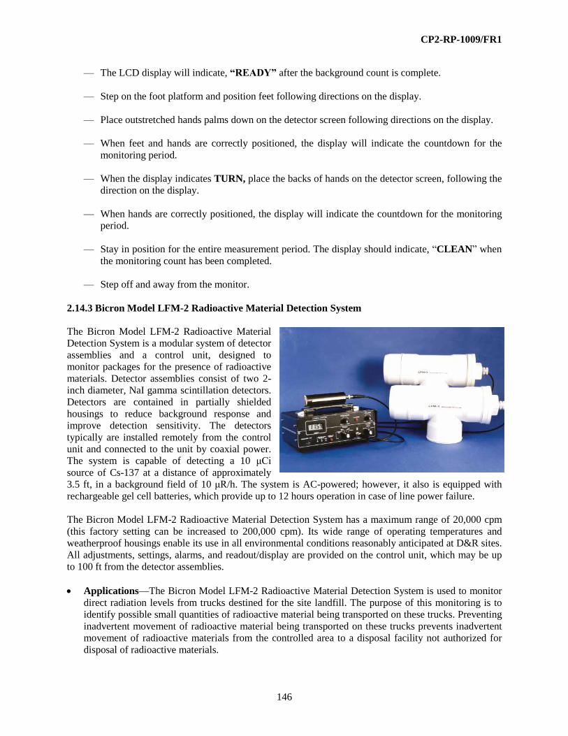
CP2-RP-1009/FR1
146
— The LCD display will indicate, “READY” after the background count is complete.
— Step on the foot platform and position feet following directions on the display.
— Place outstretched hands palms down on the detector screen following directions on the display.
— When feet and hands are correctly positioned, the display will indicate the countdown for the
monitoring period.
— When the display indicates TURN, place the backs of hands on the detector screen, following the
direction on the display.
— When hands are correctly positioned, the display will indicate the countdown for the monitoring
period.
— Stay in position for the entire measurement period. The display should indicate, “CLEAN” when
the monitoring count has been completed.
— Step off and away from the monitor.
2.14.3 Bicron Model LFM-2 Radioactive Material Detection System
The Bicron Model LFM-2 Radioactive Material
Detection System is a modular system of detector
assemblies and a control unit, designed to
monitor packages for the presence of radioactive
materials. Detector assemblies consist of two 2-
inch diameter, NaI gamma scintillation detectors.
Detectors are contained in partially shielded
housings to reduce background response and
improve detection sensitivity. The detectors
typically are installed remotely from the control
unit and connected to the unit by coaxial power.
The system is capable of detecting a 10 μCi
source of Cs-137 at a distance of approximately
3.5 ft, in a background field of 10 μR/h. The system is AC-powered; however, it also is equipped with
rechargeable gel cell batteries, which provide up to 12 hours operation in case of line power failure.
The Bicron Model LFM-2 Radioactive Material Detection System has a maximum range of 20,000 cpm
(this factory setting can be increased to 200,000 cpm). Its wide range of operating temperatures and
weatherproof housings enable its use in all environmental conditions reasonably anticipated at D&R sites.
All adjustments, settings, alarms, and readout/display are provided on the control unit, which may be up
to 100 ft from the detector assemblies.
Applications—The Bicron Model LFM-2 Radioactive Material Detection System is used to monitor
direct radiation levels from trucks destined for the site landfill. The purpose of this monitoring is to
identify possible small quantities of radioactive material being transported on these trucks. Preventing
inadvertent movement of radioactive material being transported on these trucks prevents inadvertent
movement of radioactive materials from the controlled area to a disposal facility not authorized for
disposal of radioactive materials.
CP2-RP-1009/FR1
147
Controls and Displays
— Alarm Light—Indicator is lit whenever the alarm set point is reached in the RATE mode.
— Alarm Set—Enables unit alarm level to be set for 1–130% of full scale in rate mode using a
potentiometer located below the words ALARM SET. The set point is displayed on the LCD.
— bat.—Enables a check of the condition of the internal batteries. Battery condition is displayed on
the LCD display.
— HV—Voltage for the detectors is displayed on the LCD display.
— Rate—In this position, the unit displays the count rate (in thousands of counts/minute) on the
LCD display.
— Audio Switch—Controls the function of the internally mounted speaker. In the OFF position, the
speaker is disabled; in the PULSE position, the speaker provides an audible click for each
detected event until the preset alarm level is reached, at which point the clicking is replaced by a
continuous tone; in the ALARM position, the alarm functions, but the audible clicking at lower
rates is disabled.
— Detector Status Lights (2)—Green light switch to indicate detectors are providing signals and
that electronics are receiving and registering signals; if either detectors or electronics fail, the
appropriate light turns off.
— DISPLAY RESET BUTTON—Depressed to provide rapid reset of LCD display to ZERO.
Also doubles as an alarm reset.
— Display—As indicated above, the LCD display is used to display the operating settings of the
unit and the results monitored by the detectors.
— Power Indicator Light—Amber light is illuminated when AC power is on.
— Power On Switch—Turns the unit on and off.
— Ratemeter Control (“Mode”) Switch—This switch controls the mode of operation for the
ratemeter.
— Response Control—Selects instrument response time (90% of full reading) from 2–20 seconds.
— Volume Control—Allows adjustment of the level of the audible clicking; there is no adjustment
available for the volume of the alarm signal.
Additional Features and Auxiliary Equipment—There are no items of auxiliary equipment
required to use the Bicron Model LFM-2 Radioactive Material Detection System. The unit can be
used with a recorder connected to an outlet on the rear panel.
Limitations and Precautions—The detector assemblies are contained in protective housings that
restrict low-energy photon radiation from reaching the detectors, thus lowering sensitivity to
materials, which emit only low-energy photon radiations. Except for possible small amounts of
bremsstrahlung production by beta particles, the detectors will not detect the presence of materials

CP2-RP-1009/FR1
148
emitting only beta or alpha radiations. Sensitivity of the system will vary for different radioactive
materials, because of the energy-dependent response of NaI to photon radiations. Because of the
shielding, detector response is directional; the maximum response is from the area designated for
vehicles and packages to pass by the detectors and in a position perpendicular to detector centerline.
This unit should not be operated in an explosive or combustible atmosphere.
Operation
— Ensure that when the instrument is in use, the instrument performance tests have been
satisfactorily completed (all reading are within the defined acceptable range) within the last
month and documented on a “Performance Response Check Sheet for Boundary Control Station”
form or equivalent in accordance with established procedure.
— To begin operation or to check for proper operation of unit, first confirm that the instrument
calibration is current per information on the label to the control unit. Then perform the following:
– Unplug instrument and position ratemeter control switch to bat; if display is greater than
10.0 volts, batteries are charged and instrument can be operated on battery power. If not
greater than 10.0 volts, connect to AC power and turn power on by pushing the power on
switch to the right. Observe battery response and, if batteries are not recharging, turn the
power off, remove unit from service, and notify instrument group personnel.
– If battery test is satisfactory, turn the power on by pushing the power on switch to the right.
Confirm that the amber AC power light is illuminated.
– Position ratemeter control switch the HV and observe LCD display; compare HV value to
that indicated on instrument label or performance check records. If displayed voltage is not
within ± 10 volts of the listed voltage, remove unit from service and notify instrument group
personnel.
– Position the ratemeter control switch to rate; the audio switch to alarm; and the volume
control to maximum (full clockwise).
– Observe detector indicator light; ensure each green light is illuminated and the detectors are
responding within the typical expected background range or remove unit from service and
notify instrument group personnel.
– If reset of the alarm set point is desired, turn the ratemeter control switch to alarm set and
adjust for desired setting using the potentiometer near the control switch. Return the
ratemeter control switch to rate.
– Confirm that background levels are in the normally expected range or remove from service
and notify instrument group personnel. Observe that data are being recorded if recorder is
connected.
– Proceed to collect monitoring data.
— When measurements are completed, the instrument may be turned off by pushing the power on
switch to the right.

CP2-RP-1009/FR1
149
2.14.4 Global Positioning System Gamma Ray Survey Instrumentation
The Global Positioning System (GPS) consists of a Trimble
Pro XRS (backpack with antenna) with a TSC1 hand-held
computer and data logger.
The Pro XRS receives signals from the 24 NAVSTAR
Department of Defense satellites and accurately computes
the position (coordinates) of the GPS antenna. A separate
Landstar satellite provides another signal that allows the Pro
XRS to perform live-time position corrections.
The gamma detection system is connected to the TSC1 and
consists of a modified Ludlum Model 2221 with a Ludlum
44-10, 2-inch x 2-inch NaI (Tl) gamma scintillation detector.
Gamma ray count rates are received by, and recorded within,
the TSC1 at two-second scaled intervals during movement
over the areas to be characterized. The count rates are logged
with the corresponding state planar coordinates that are also
recorded every two seconds.
NOTE: This Topical Guide describes steps for conducting
field gamma walkover surveys. This guide does not include
the pre-survey planning and setup, and does not include
steps for post-survey data reduction and processing.
Applications—The GPS gamma surveys are intended to characterize gamma ray intensities over
extended paved and land areas. The gamma count rates have only relative value. The count rates can
be compared to ambient background count rates to suggest biased sampling locations to determine
radionuclide concentrations. With proper consideration, a correlation of the gamma count rate to the
gamma ray dose rate may be possible by measuring the identical location with a tissue-equivalent
organic scintillation detector (e.g., Bicron MicroRem Meter).
System Assembly—Connect the system components. The Ludlum Model 2221 must always be
connected to the top port of the TSC1 through a data cable. The other data cable, from the Pro XRS
receiver (backpack), must always be connected to the bottom port of the TSC1. It is possible to
reverse these connections, because the connectors physically are identical.
Controls and Displays—For the operation of the Ludlum Model 2221 with the Ludlum Model 44-10
detector, refer to Section 3.6.6 and Section 3.7.10, of the Topical Guide, respectively. All of the
necessary controls and displays are provided by the TSC1.
Operation
— Before initiating the GPS survey, measurements with the Ludlum 2221 and 44-10 will be taken to
measure and record the ambient background. Recognize that gamma ray “shine” from adjacent
facilities may affect the background and possibly the entire survey. This phenomenon becomes
more evident when surveying low-lying areas shielded by surrounding hills.

CP2-RP-1009/FR1
150
— ON/OFF KEY—Turns the system on and off. When turned on, the Main Menu will appear on
the LCD screen. Expect some delay before the entire screen is displayed. [Press Fn and E to
lighten the screen and Fn and F to darken.]
— If a “No GPS detected” screen appears instead of the main menu, check all cable connections and
batteries. Pressing the F1 key may pull up the Main Menu.
— The Main Menu screen is accompanied by icons at the bottom of the LCD.
— The battery icon at bottom left of the LCD shows the battery status; all black means fully
charged.
— The PC icon means that a PC card has been inserted for extended memory.
— It is necessary to be properly positioned in the field for positive indications on the remaining
icons (e.g., be away from obstructions that intercept the GPS signals).
— Another icon will appear that is an antenna and satellite. This indicates that real time correction
signals are being received from the Landstar satellite service.
— CAUTION: Do not proceed to survey until that icon appears.
— The “6” displayed in the icon, means that six NAVSTAR satellites are being tracked by the GPS.
A minimum of four is required for any survey.
— The position dilution of precision (PDOP) must be less than 6. This relates to the spread or
uniform distribution of the NAVSTAR satellites across the sky.
— If a flashing message “Too few SVs” appears, this means that less than four NAVASTAR
satellites are available to the GPS. Stop surveying (pause). There may be an obstruction (building,
tree, or some other object) blocking the antenna. Move to a new position until four or more
satellites are being received. Otherwise, this can be a temporary (less than one-half hour) satellite
orbit condition.
— When stepping through the various menus and functions, the TSC1 will issue audible “beeps.”
Three beeps mean operations are proceeding normally. A single beep indicates some problem.
— Main Menu—With the Data Collection highlighted, press ENTER. The Multi-directional arrow
key will move the highlight in any menu. If another submenu is displayed, press Menu or press
Esc until the Main Menu appears.
— Data Collection Menu—Three items appear on the Data Collection Menu:
(1) Create a new file
(2) Open an existing file
(3) Create base file (never used in our application)
– At the end of a survey day, the files on the TSC1 will be downloaded to a PC. Starting a
survey on a new day entails creating a new file. Ensure that the radiation detector is
connected and turned on. Sensor 1 will appear on the screen.

CP2-RP-1009/FR1
151
– Sensor 1 will be displayed on the screen. Highlight Create a new file and press ENTER. The
TSC1 automatically assigns and displays a new and exclusive filename. Press ENTER to
open the new file for logging. (The first filename of any day will have a final alpha character
A. The next filename would end with B, etc.)
– The data collection begins. Pressing the key just below Pause stops data collection. The LCD
display changes to Resume and pressing the same key resumes the data collection.
– During any given day, the field survey may move to another location and/or survey with
another detector. That will require Create a new file and this new file will be used for
logging.
– If a survey returns to the location of an earlier file, then Open an existing file will enable
supplemental data collection to that file.
– Either write down the area represented by each file or rely upon the coordinates shown in the
file.
– When a survey is completed, press the Esc key. Confirm that you wish to exit data collection.
— Elevated Area—The Data Dictionary has established a record entitled Elevated Area. If a
location is encountered that is equal to, or greater than, twice the area background, press Pause,
toggle to highlight Elevated Area, and press ENTER. Information is requested that must be filled
in before the survey can continue. The required information includes the gamma ray dose rate
(Bicron Micro Rem Meter), the alpha emitter surface contamination level, and the beta-gamma
emitter surface contamination level. The estimated area of concern (e.g., square feet) also is
entered.
— Useful Menus During the Survey—During the survey, a map of the data logging is displayed by
accessing the MAP menu from the Main Menu. This map display shows the progress of data
point accumulation and directs the surveyor to cover any areas with missing or lower density data
points. A zoom in/zoom out feature enhances the assessment. The objective is uniform coverage
of the area.
If the LCD display shows too few satellites or a PDOP greater than six, the geometry of the
satellites across the sky can be viewed through the Satellite information menu. One can observe
the satellites that are out of the range and/or about to come into range. Further, this can be used to
help determine if there is some local interference between the GPS antenna and the satellites.
Table 3. Configuration Menu
Setting Value Configuration Menu Entry
Logging Intervals
Point feature
Line and area features
Not in feature
Velocity
2 Seconds GPS Rover Options/Logging Operations
Minimum positions (point
feature)
3 GPS Rover Options/Logging Operations
Position Mode Manual 3D GPS Rover Options/Position Filters
Elevation Mask 15 GPS Rover Options/Position Filters
Signal-to-noise ratio (SNR)
Mask
6.0 GPS Rover Options/Position Filters
PDOP Mask and switch 6.0 GPS Rover Options/Position Filters

CP2-RP-1009/FR1
152
— Landstar Satellite Icon—It is important to monitor the Landstar satellite icon continually. If the
icon disappears, pause the survey. If the icon does not reappear after ~ 15 minutes, convey that
condition to the supervisor for remedy.
NOTE: Many potentially adverse conditions are signaled by an audible single beep, but there is
no audible beep when Landstar communication is lost.
— Configuration Menu—It is not necessary to access the Configuration Menu and NONE of the
PRESET VALUES are to be CHANGED in the FIELD. In the event of an apparent problem, this
menu can be accessed to ensure that the critical parameters have been properly set. Those are
summarized below.
— Rebooting the TSC1—If the TSC1 computer locks up, a “warm boot” usually frees up the
system. Turn off the TSC1 by holding down the ON/OFF key for one second. Then hold down
the Bksp and press and release the ON/OFF key.
After three “beeps” from the TSC1, release the backspace key. If this does not free up the TSC1,
return to the office.
WARNING: Do not attempt a “cold boot,” because all of the data and settings will be lost.
2.14.5 Canberra InSpector Gamma Spectrometer
The Canberra InSpector is a portable battery operated,
digitally stabilized, MCA, with an internal high voltage power
supply and amplifier, connected to a portable high purity
germanium (HPGe) counting system. The current HPGe
detector is a 2,000 mm2 by 20 mm in a 5-liter portable
cryostat with a loss rate of about 1 liter per day. The HPGe is
used while suspended from a tripod in an upside down
position with the crystal 1 meter above the ground. A lead
collimator (shield) may be employed to minimize the
contribution of distant gamma sources from outside the
desired area. The detector connects to the InSpector MCA; it
also receives its power from the Inspector. The 3.2 pound
Inspector is powered by two rechargeable batteries or it can be
plugged into a standard 110 VAC outlet. The Inspector
connects to a laptop computer running the Canberra ProCount
software. The Canberra In Situ system employs a Monte Carlo
calibration scheme using the MCNP code. With this scheme,
the system is shipped already calibrated for in situ work. The
computer can be powered either off a rechargeable battery or
plugged into a standard 110 VAC outlet.
Applications—The InSpector is useful for decommissioning and decontamination work, safeguards
related measurements for special nuclear materials, and many other in situ applications. The current
system is efficiency pre-calibrated for the 1 meter above the ground geometry with a lead collimator.
Controls and Displays—There are no external controls; the Inspector is operated from the notebook
computer. Two lights on the front of the Inspector indicate the battery condition, and HV/count status.

CP2-RP-1009/FR1
153
Additional Features and Auxiliary Equipment—A check source for energy calibration verification
is needed. Cs-137 or uranium may be used.
Limitations and Precautions
— The tripod and collimator are heavy; avoid strains and sprains by using good practices while
moving them.
— The Inspector should not be used while it is raining, or when the temperature is not between 32°F
and 122°F.
— Liquid nitrogen can cause severe injury if splashed on unprotected skin. Inspect all tubing for
damage and ensure connections are tight before transfer into the cryostat.
Operation
— After connecting all the components and cooling the crystal, the computer and Inspector can be
turned on.
— The ProCount program should be started. Select Detector Management, then Hardware
Control to ensure that high voltage is ON.
— Return to the main menu and expand the MCA window. Under “File” select “Open Data
Source” and select the detector. Under “MCA,” select “Adjust” to open the adjustment panel at
the bottom of the window, and then select “Amp.”
— Expose the energy check source to the detector. Select “Acquire On” to start collecting counts,
then adjust the amplifier gain to get the energy peak to the correct location. Make small
adjustments and “Clear” the accumulated counts after each adjustment. When the gain is
properly set, select “File” and “Close,” and save the changes using the name suggested by the
program. Minimize the MCA window.
— To count samples, select “Sample Counting” and “COLLIMATED SEMI-INFINITE FLD @
1M,” select/enter appropriate run time (usually 300 seconds), enter sample parameters and the
unit will perform a count.
— To view results, select Detector Management, then select the detector and then select “View
Last Report.” Depending on the complexity of the spectrum, the report may take a few minutes
to be generated after the count is complete.

CP2-RP-1009/FR1
154
2.14.6 Genitron Gamma Tracer Area Monitor
The Gamma TRACER is a combination of a G-M based survey instrument and a microprocessor
controlled data logger in a compact environmentally
sealed package. The Gamma TRACER employs two
energy compensated GM detectors. The dose rate may be
integrated over 1, 2, 5, 15, 30, 60, and 120 minute
increments. The interior of the Gamma TRACER probe
is sealed hermetically and a silica gel cartridge ensures a
permanently safe atmosphere, free of humidity, in the
interior casing. The case is 29-inches long with a
diameter of 2-3/8 inches. An IR reader is used to
download accumulated data.
Applications—The Gamma Tracer provides
independent verification of annual dose rates and around nuclear facilities. The Gamma Tracer may
be used to supplement existing monitoring systems in emergencies. Improved time resolution
compared to TLDs with equivalent sensitivity. Monitor temporary waste storage, disposal sites, or
transport operations.
Controls and Displays—There are no controls or displays on the Gamma Tracer; a PC functions as
the “control panel.”
Additional Features and Auxiliary Equipment—A source holder jig and 100 μCi shielded Cs-137
Check source are available. A dose rate alarm is optional as well as extended dose rate temperature
ranges.
Limitations and Precautions
— The operating range is 2 μrem/h to 1 rem/h.
— The operating temperature range of the Gamma Tracer is -4°F to 122°F.
— The battery life is reduced at high dose rates and short integration times (less than 10 minutes).
Up to 12,800 measurements may be stored internally.
Operation
— The IR Transceiver is used to download the stored data to a computer running the Gamma View
software. After download, the data may be exported into database or spreadsheet programs.
— Set the PC up for download by running the view program from DOS. Select the “noname” title
bar and select “Clear Window.”
— Select the download icon (bottom right icon that looks like a computer screen with a gamma
tracer).
— Line up the gamma tracer with the IR Transceiver. Make sure the light on the transceiver turn
green when pressing the button on the back of the transceiver.
— Change the 9 V battery if it turns red instead of green.

CP2-RP-1009/FR1
155
— Select number 8 to change the S/N of the gamma tracer. Type in the Gamma Tracer S/N (use
upper case letters only) and press ENTER.
— Select number 4 (Status Report) and ensure Dose Rate #1 and Dose Rate #2 are close together.
Note the dose rates on the printout if they are not.
— Select number 1 to transmit new data (this takes about 15 minutes).
— Select 0 to exit and select Yes when you are asked if you want to quit.
— When the graph appears, select the file name from the logbook and save the data.
— Print the data.
2.14.7 Canberra Argos-4A.B Whole Body Monitor
The Argos-4A.B Whole Body Monitor uses
23 400-cm2
detectors (LFP-400) to provide
10 400-cm2 of active monitoring area in
each of two steps for total body coverage.
The detection surface is contoured to
conform to a more natural body shape
while minimizing gap between an
individual and an active detector window.
Additional detectors give improved side
coverage with specific attention to the
pocket area, the outer part of the lower legs,
and the top of shoes. The Argos-4A.B uses
thin Mylar (aluminized on both sides)
window large-area gas flow proportional
detectors for excellent alpha and beta
sensitivity. The Argos-4A.B is ideal for
monitoring at exit boundaries.
The Argos-4A.B is a two-step monitor. The
base section contains 2-ft detectors
(LFP-400) and two IR foot position
sensors. The top section contains one head
detector (LFP-400), the LCD screen, the audio speakers, two passive IR motion sensors for body
approach detection and occupied detection, and an IR background suppression body position sensor. The
vertical cabinet contains the computer box with its low voltage power supply and carrier board, the
electrical utility panel, FAULT and READY annunciator LEDs, three hand arm detectors (LFP-400),
fifteen body/clothing detectors (LFP-400), one shoulder detector (LFP-400), and two hand position
sensors. A small door on the front of the cabinet provides access to a keyboard connector, a printer
connector, and a VGA connector for an external monitor that can be operated in parallel with the built-in
LCD display. The hinged side cabinet contains three vertical detectors (LFP-400) and one hand detector
(LFP-400). The main detector array and the side/hand detector array are hinged to allow an easy access to
all the detectors from the front.

CP2-RP-1009/FR1
156
Sensors—The Argos-4A.B uses a combination of sensors to detect user movement and positioning
on the monitor as shown in the following table (the number of sensors used is indicated in brackets):
Table 4. Sensors
Sensor Name Type Location Function
Approach Sensor A(1) Passive IR motion
sensor (disc type)
Roof Detect approach, stop
background update
Occupied Sensor(1) Passive IR motion
sensor (spy type)
Roof Detect personnel in
monitor
Hand Sensor –
Left (1)
Right (1)
Photoelectric
Transmit/Receive
Visible red
Transmit/Receive
IR
Across middle of hand Detect positioning of
hand
Foot Sensor (2) Photoelectric
IR bkg suppression
Kickpanel Detect feet on grills
Body Sensor (1) Photoelectric
IR bkg suppression
Head detector panel Detect body close to
body detectors
Application—The Argos-4A.B Whole Body Monitor is designed for the measurement of alpha and
beta contamination on skin, shoes, and clothing. The Argos-4A.B typically is used at fixed control
points.
Controls and Displays—The Argos-4A.B Whole Body Monitor display will indicate automatic
measurements being performed by the instrument or will indicate instrument abnormalities. The
audible messages provided by this instrument may be disabled, if desired.
— Clean—The LCD display and audible message indicate none of the detector measurements has
exceeded the release alarm level. The user should leave the monitor platform.
— Contaminated—The LCD display and an audible message indicate one or more detector
measurements have exceeded the release alarm level.
— Initializing Background—The LCD display indicates a background measurement is in progress;
a contamination measurement is not possible.
— Monitor—When the user is correctly positioned on all four detectors, an audible countdown
begins and is indicated on the LCD display: 60, 50, 40, 30, and 20 through 1 seconds.
— On/Off—This switch, located in the vertical cabinet, supplies power to the monitor.
— Out of Service—The LCD display indicates that the instrument has one or more contaminated
detectors or a system fault has been detected. If a system fault has been detected, the LCD display
will indicate what fault has occurred (e.g., HIGH BACKGROUND RATE).
— “Please Exit”—This audible message is initiated if any position sensor are still activated for two
or more seconds after monitoring is complete.
— Please Wait Contamination Check—The LCD display indicates that the monitor is performing
a detector surface contamination check after the user has exited the monitor.

CP2-RP-1009/FR1
157
— Position Hands, Feet, and Body—The LCD display and an audible message provide direction to
the user for positioning hands, feet and body and will indicate when all are correctly positioned
on the detectors.
— Ready—The LCD display indicates that the monitor is ready to monitor personnel.
— Fault—The LCD display indicates that the monitor is in a FAULT Condition and is not ready for
use. Notify the instrument group.
— “Thank You”—This audible message is initiated when the user has not exited the platform in the
pre-set time.
— “Turn”—The LCD display and an audible message direct the user to “Please turn around” for
measurements on the back of the user’s hands. The monitor re-initializes the POSITION mode.
Additional Features and Auxiliary Equipment—No additional features or auxiliary equipment is
included.
Limitations and Precautions
— Detector gas pressure should never exceed 2 psig. Pressures greater than 2 psig will damage the
detectors.
— Detector Mylar and foot grates always must be clean. Clean using a smooth cloth. The Mylar is
very fragile and can easily be damaged. Do not use any compressed air or hard objects for
cleaning as damage may occur to the Mylar and detector.
Operation
— Ensure that the instrument has a current and legible calibration label; if not, remove from service
and do not use until the condition is corrected.
— Ensure that when the instrument is in use, the weekly instrument performance tests have been
satisfactorily completed (all reading are within the defined acceptable range) and documented on
a “Performance Response Check Sheet for Boundary Control Station” form or equivalent in
accordance with established procedure.
— Ensure that the gas supply is connected to the monitor and the gas pressure indicated on the
regulator gauge indicates ≤ 2 psig and that the gas flow rotameter indicates a flow rate of
approximately 20–25 cc/min. If gas pressure is available, but no flow rate is indicated, remove
from service and do not use until the condition is corrected.
— Ensure that the power ON/OFF switch is in the ON position.
— Verify Ready Light on the side of the monitor is On.
— If Ready Light is not On and the Fault Light is On, then notify the instrument group.
— Step on the platform facing the monitor and position your head, body, arm, and feet close to the
monitor until all body sensors are activated and the monitor begins the countdown.

CP2-RP-1009/FR1
158
— Hold this position until “Please Turn Around” is announced.
— Turn around in the monitor to begin the second part of the whole body monitoring process and
hold the position until the monitor announces the survey is complete.
— If “Clean” is announced, step off the monitor.
— If “Contaminated” is announced then:
(1) Step away and allow the monitor to reset.
(2) Repeat entire survey, front and back.
If you get a second contaminated announcement, do not leave the area and immediately notify
your supervisor.
2.14.8 Canberra iSolo® Alpha/Beta Counting System
This system provides measurements of transuranic
and fission product activity on filter samples in the
presence of radon/thoron interferences. The iSolo ®
is
designed specifically for the analysis of filter samples
to detect the presence of radon, thoron, and their
progeny and compensate for the interference.
This is achieved through the application of auto-
adaptive spectrometric compensation for the
radon/thoron interferences. The radon/thoron
compensation algorithm adjusts to all types of filter
media, from glass fiber filter media for smear analysis
to membrane-type filter media for air sampling. The
system provides gross alpha/beta results. A series of
peak evaluations are performed on the original acquired spectrum. After the application of corrections, the
system reports radon-compensated true alpha and beta activity.
Detector—The iSolo® contains a silicon oxide (SiO2) passivated implanted planar silicon detector.
This thin window not only improves typical resolution, as normally measured, but it exhibits an even
greater improvement at close detector-source spacing, which is necessary to achieve the high
efficiency required for low-level alpha spectroscopy.
Controls—The iSolo® is completely controlled by the front panel keys and a liquid crystal display.
The keys are color coded and logically grouped. Count data is displayed on the LCD.
— Power—Green LED indicates when the unit is on an external power supply, and the unit is
turned on. Yellow LED indicates the unit is powered by the charged battery.
— Battery—Green LED indicates that the batteries have sufficient charge to operate the unit.
Yellow LED indicates the batteries are near the end of their charge, and the unit will shut down in
10–15 minutes.
— Display—Display key is used to adjust the display contrast and viewing angle for best visibility.

CP2-RP-1009/FR1
159
— View—Press the view key to view the calibration and sample data.
— Print—The print key provides several functions.
— Bkg, α Eff., β Eff. Keys—Preprogrammed hot keys linked to special count procedures to
perform routine verification of background and efficiency.
— Select Procedure Key—This key allows you to choose the desired counting procedure. By using
the numeric keypad, one can select from different options.
— Count Key—This key starts the count procedure shown in the display. It also serves as a
count/pause control.
— Group Done Key—When counting several samples in the same data batch, this key is used to
indicate the completion of the batch count.
— Arrow Keys—Allow the user to navigate through the system, as well as the selection of the
alpha-numeric characters.
— Enter, Cancel, and Setup Keys—Special function keys to confirm data entry, cancel an
operation, and enter the system setup function.
Limits and Precautions—The PIPs detector is sensitive to gamma radiation. Verify that all sources
have been stored in their appropriate storage designation and not being used in the vicinity of the
instrument when using.
When counting samples, wait a minimum of 30 minutes since air sample was pulled prior to counting.
Operation—Calibration of Unit
— Enter calibration source information
– Select desired source template for both calibration and QC checks.
– Modify the source information.
– Enter the count time minutes.
– Enter the active source area in mm.
– Enter the source activity in dpm.
– Repeat the above steps for each source to be entered.
— Modify calibration procedures
– Modify the calibration name.
– Enter the active source area in mm.
– Enter the background count time in minutes.
– Enter the number of background counts.
– Select background blank.
– Enter the alpha efficiency count time in minutes.
– Enter the number of alpha counts.
– Enter the alpha efficiency source.
– Enter the beta efficiency count time in minutes.
– Enter the number of beta counts.

CP2-RP-1009/FR1
160
– Enter the beta efficiency source.
— Selecting printer output mode
– Press print key and select output setup.
– Select output mode.
– Select end of group.
— Modifying the daily QC procedures
– Select Quality Control from the menu.
– Select Define QC procedure.
– Select daily background parameters.
– Select count time.
– Enter the daily background measurement in minutes.
– Enter the number of background counts.
– Select daily alpha efficiency parameters.
– Enter the alpha source count time.
– Enter the number of alpha counts.
– Select daily beta efficiency parameters.
– Enter the beta source count time.
– Enter the number of beta counts.
— Perform initial calibration
– Select calibrations from the setup menu.
– Select execute calibration.
– Select which calibration to perform from the menu.
– Select background.
– Place the background blank into the slide and close slide.
– Press the enter key.
– Select count from the front panel.
– After the background count is complete, press enter to accept the results.
— Alpha efficiency calibration
– Select calibrations from the setup menu.
– Select execute calibration.
– Select which calibration to perform from the menu.
– Select alpha efficiency from the menu.
– Place the alpha source in the slide, and close the slide. Press the enter key.
– Select count from the front panel.
– After the count is completed, press enter to accept the results.
— Beta efficiency calibration:
– Select calibrations from the setup menu.
– Select execute calibration.
– Select which calibration to perform from the menu.
– Select beta efficiency from the menu.
– Place the beta source in the slide, and close the slide. Press the enter key.

CP2-RP-1009/FR1
161
– Select count from the front panel.
– After the count is completed, press enter to accept the results.
— Perform the initial daily QC procedure
– Select quality control from the menu.
– Select execute QC procedure.
– Select daily background.
– Follow the directions from the screen to execute the background count.
— Alpha efficiency QC
– Select quality control from the menu.
– Select execute QC procedure.
– Select daily alpha efficiency from the menu.
– Follow the directions from the screen to execute the background count.
— Beta efficiency QC
– Select quality control from the menu.
– Select execute QC procedure.
– Select daily beta efficiency from the menu.
– Follow the directions from the screen to execute the background count.
Daily QC Check and Sample Counting
— Daily QC for background
– Press daily bkg on the iSolo® front panel.
– Select the appropriate source (bkgblank) and press enter.
– Place the bkg planchet in the holder, close holder.
– Press the enter key.
– Upon completion, press the enter key to accept background results.
— Daily QC for alpha efficiency
– Press daily alpha eff. on the iSolo ® front panel.
– Select the appropriate source (Pu-239d) and press enter.
– Place the alpha source in the holder, close holder.
– Press the enter key.
– Upon completion, press the enter key to accept alpha efficiency results.
— Daily QC for beta efficiency
– Press daily beta eff. on the iSolo ® front panel.
– Select the appropriate source (Tc-99d) and press enter.
– Place the beta source in the holder, close holder.
– Press the enter key.
– Upon completion, press the enter key to accept beta efficiency results.

CP2-RP-1009/FR1
162
— Counting samples
– Place the first sample in a planchet into the holder and close holder.
– Press select procedure to list the available counting procedures.
– Place the cursor next to the procedure wanted (alpha compensated), and press enter.
– Press count to start the analysis.
– Repeat this process for all other samples.
– When completed, press group done.
– Declare that the group is done by pressing 2.
2.14.9 Canberra Argos-5AB Whole Body Monitor
The Argos-5AB Whole Body Monitor uses twenty-five
579-cm2 detectors (LFP-579) to provide active monitoring area
in each of two steps for total body coverage. The detection
surface is contoured to conform to a more natural body shape
while minimizing gap between an individual and an active
detector window. The Argos-5AB uses thin Mylar (aluminized
on both sides) window large-area gas flow proportional
detectors for excellent alpha and beta sensitivity. The
Argos-5AB is ideal for monitoring at exit boundaries.
Sensors—The Argos-5AB uses a combination of sensors
to detect user movement and positioning on the monitor.
Application—The Argos-5AB Whole Body Monitor is
designed for the measurement of alpha and beta
contamination on skin, shoes, and clothing. The Argos-
5AB typically is used at fixed control points.
Controls and Displays—The Argos-5AB Whole Body
Monitor display will indicate automatic measurements
being performed by the instrument or will indicate
instrument abnormalities. The audible messages provided by this instrument may be disabled, if
desired.
— Clean—The LCD display and audible message indicate none of the detector measurements has
exceeded the release alarm level. The user should leave the monitor platform.
— Contaminated—The LCD display and an audible message indicate one or more detector
measurements have exceeded the release alarm level.
— Initializing Background—The LCD display indicates a background measurement is in progress;
a contamination measurement is not possible.
— Monitor—When the user is correctly positioned on all four detectors, an audible countdown
begins and is indicated on the LCD display: 60, 50, 40, 30, and 20 through 1 seconds.
— On/Off—This switch, located in the vertical cabinet, supplies power to the monitor.

CP2-RP-1009/FR1
163
— Out of Service—The LCD display indicates that the instrument has one or more contaminated
detectors or a system fault has been detected. If a system fault has been detected, the LCD display
will indicate what fault has occurred (e.g., HIGH BACKGROUND RATE).
— “Please Exit”—This audible message is initiated if any position sensor are still activated for two
or more seconds after monitoring is complete.
— Please Wait Contamination Check—The LCD display indicates that the monitor is performing
a detector surface contamination check after the user has exited the monitor.
— Position Hands, Feet, and Body—The LCD display and an audible message provide direction to
the user for positioning hands, feet and body and will indicate when all are correctly positioned
on the detectors.
— Ready—The LCD display indicates that the monitor is ready to monitor personnel.
— Fault—The LCD display indicates that the monitor is in a FAULT Condition and is not ready for
use. Notify the instrument group.
— “Thank You”—This audible message is initiated when the user has not exited the platform in the
pre-set time.
— “Turn”—The LCD display and an audible message direct the user to “Please turn around” for
measurements on the back of the user’s hands. The monitor re-initializes the POSITION mode.
Additional Features and Auxiliary Equipment—No additional features or auxiliary equipment is
included.
Limitations and Precautions
— Detector gas pressure should never exceed 2 psig. Pressures greater than 2 psig will damage the
detectors.
— Detector Mylar and foot grates always must be clean. Clean using a smooth cloth. The Mylar is
very fragile and can easily be damaged. Do not use any compressed air or hard objects for
cleaning as damage may occur to the Mylar and detector.
Operation
— Ensure that the instrument has a current and legible calibration label; if not, remove from service
and do not use until the condition is corrected.
— Ensure that when the instrument is in use, the weekly instrument performance tests have been
satisfactorily completed (all reading are within the defined acceptable range) and documented on
a “Performance Response Check Sheet for Boundary Control Station” form or equivalent in
accordance with established procedure.
— Ensure that the gas supply is connected to the monitor and the gas pressure indicated on the
regulator gauge indicates ≤ 2 psig and that the gas flow rotameter indicates a flow rate of
approximately 20–25 cc/min. If gas pressure is available, but no flow rate is indicated, remove
from service and do not use until the condition is corrected.

CP2-RP-1009/FR1
164
— Ensure that the power ON/OFF switch is in the ON position.
— Verify Ready Light on the side of the monitor is On.
— If Ready Light is not On and the Fault Light is On, then notify the instrument group.
— Step on the platform facing the monitor and position your head, body, arm, and feet close to the
monitor until all body sensors are activated and the monitor begins the countdown.
— Hold this position until “Please Turn Around” is announced.
— Turn around in the monitor to begin the second part of the whole body monitoring process and
hold the position until the monitor announces the survey is complete.
— If “Clean” is announced, step off the monitor.
— If “Contaminated” is announced then:
– Step away and allow the monitor to reset.
– Repeat entire survey, front and back.
If you get a second contaminated announcement, do not leave the area and immediately notify
your supervisor.
2.14.10 Berthold LB 1043 AS Hand and Foot Monitor
The Berthold LB 1043 AS Hand and Foot Monitor is a microprocessor controlled hand and foot monitor
that includes a hand-held detector for monitoring clothing. The 1043AS is designed for the measurement
of alpha and beta radiation. The 1043 AS monitor display provides simultaneous indication of alpha and
beta measurements. This instrument utilizes large-area gas proportional detectors. P-10 gas is supplied to
the detectors via a connection on the rear panel.
Radiation background measurements made by the 1043 AS allow for background compensation; personal
contamination measurements can be performed in areas where background radiation fluctuates. The LB
1043 AS is powered by 110-volt AC electrical power.
The monitor detector array consists of four hand detectors, a foot detector that is electrically divided into
two chambers, and a clothing probe. All detectors utilize separate high voltage power supplies and alpha-
beta discriminators.
The Berthold LB 1043 AS Personal Contamination Monitor includes a foot pedestal with a light sensor
that illuminates when foot positions are correct; a base connection for the foot detector and a pneumatic
plug-in module for the counting gas supply. The hand monitor housing rests on the base and provides two
chambers, each containing two detectors for each hand. An electronic unit provides a signal lamp that
indicates the READY status of the monitor. The front panel of the electronic unit features a keypad,
function keys, LED display, contamination pictogram, trend display for the hand-held detector and a
barcode reader. The rear panel features a power on-off switch, sockets for detector input/output, external
alarm connection, and serial port connectors for a printer and a computer. The hand-held detector is
attached to the side of the electronics panel. Removing the detector probe from the unit will activate it for
clothing measurements.

CP2-RP-1009/FR1
165
Application—The Berthold LB 1043 AS Personal Contamination Monitor is designed for the
measurement of alpha and beta contamination on skin, shoes, and clothing. The 1043 AS is typically
used at fixed control points at some D&R operations.
Controls and Displays—The Berthold LB 1043 AS Personal Contamination Monitor display will
indicate automatic measurements being performed by the instrument or will indicate instrument
abnormalities.
— BACKGROUND TOO HIGH—This display indicates the measured background radiation has
exceeded the programmed threshold.
— CONTAMINATED—This display, indicates one or more detector measurements have exceeded
the programmed threshold.
— Detec. Contam. 2b—The highest reading detector is indicated in the display. No measurement is
possible.
— DO NOT ENTER—This display indicates a background measurement is in progress, a
contamination measurement is not possible.
— LINE/OFF—This switch, located on the rear panel, supplies power to the monitor.
— NOT CONTAMINATED—This display indicates none of the detector measurements has
exceeded the programmed threshold.
— PROBE FAILURE—This display indicates that one or more detector probes has failed.
— READY FOR USE! —This display indicates that personnel may begin a contamination
measurement.
— READY—This green light will illuminate indicating that the monitor is ready to monitor
personnel.
— WAIT, BACKGROUND FLUCTUATES—This display, indicates that background radiation is
fluctuating; a contamination measurement is not possible until background has stabilized.
— WARM UP LIGHT—This amber light will illuminate indicating that the monitor is warming up
for operation.
Additional Features and Auxiliary Equipment—There are no additional features for the Berthold
LB 1043 AS Personal Contamination Monitor. This instrument may be connected to a computer and
printer.
Limitations and Precautions—The detection foil must always be clean. Clean using a smooth cloth.
The foil is very fragile and can easily be damaged. Do not use any compressed air or hard objects for
cleaning, as these may damage the foil and detector.

CP2-RP-1009/FR1
166
Operation
Note: Operation of the Berthold LB 1043 AS is possible only by means of a three of nine-
barcode card before beginning a contamination measurement. Measurement parameters (counting
time, alarm thresholds, etc.) are defined by instrumentation personnel via a bar code Master Card.
Personnel who intend to perform contamination-monitoring measurements can activate the
monitor with cards provided with a barcode. Personnel monitoring may also be initiated by
entering a numerical code using the numerical keyboard. Confirm that the Berthold LB 1043 AS
Personal Contamination Monitor has a current and legible calibration label; if not, remove from
service and do not use until condition is corrected.
— Ensure that daily instrument performance tests have been satisfactorily completed (all readings
are within the defined acceptable range) and documented on a Daily Test Sheet or perform those
tests in accordance with established procedure.
— Determine radiation field of interest. Historical, job-process, and other work documents should
provide information regarding radionuclides and types of contamination expected. This
information is available from the Radiological Control Technician Supervisor and is typically on
the Radiation Work Permit for the survey(s) to be performed. This will assist in the proper
selection of instrumentation.
— Ensure that the monitor detectors have been purged for approximately 2-4 hours.
— Ensure that the gas supply is connected to the monitor and the gas pressure indicated on the
regulator gauge indicates 2-4 pounds per square inch gravity (psig 0 and the gas flow rotameter
indicates a flow rate of approximately 5cc/min. If gas pressure is available, but no flow rate is
indicated, remove from service and do not use until condition is corrected.
— Turn the Line/Off Switch to the Line position.
— Ensure that the green READY light is illuminated. The light will illuminate approximately
10 seconds after the amber light has extinguished. If the green READY light does not illuminate
or the amber warm up light does not extinguish, remove the monitor from service and do not use
until condition is corrected.
— The monitor LED display will indicate “Ready for use!”
— Step on the foot pedestal making sure that the tips of your shoes touch the stopper.
— Pull the card through the barcode reader from top to bottom.
— Insert outstretched hands into both boxes until you touch the stopper, then press against the
stopper until the contact switches switch on with an audible click.
— Stay in position for the entire measurement period. The display will read “not contaminated”
when the monitoring count has been completed. If not, remove from service and do not use until
condition is corrected.

CP2-RP-1009/FR1
167
2.14.11 Eberline PCM-2 Personnel Contamination Monitor
The Eberline PCM-2 is a microprocessor-controlled personnel
contamination monitor that can be positioned at contamination control point
exits to obtain a fast and effective whole body measurement of any surface
radioactivity on the individual. The monitor consists of an array of 16
gas-proportional detectors with thin Mylar™ windows (0.85 mg/cm2) for
detection of both alpha and beta activity. The PCM-2 detector array
provides a total detection area of 15,552 cm2
• The monitor is operated by 110 v AC, 60 Hz electrical power.
P -10 gas is used as the counting gas for this instrument. The PCM -2
operates at a gas flow rate of 100 cc/min. The monitor is equipped with two
gas cylinders with the capability to automatically switch bottles when the
online bottle is empty. The PCM-2 includes the electronics for automatic
background subtraction. This monitor will record and display the number of
individual measurement cycles completed during a preset elapsed time
period.
The PCM-2 can be equipped with an external hand frisker that is a 100-cm2 gas proportional detector.
Gas flow rate to this detector is approximately 10 cc/min.
The detection efficiencies for the PCM-2 are as follows:
Detector Response Efficiency
Alpha (except foot) Pu-239, Am-241, Th-230 20%
Beta (except foot) Tc-99, Sr-90, Y-90 20-25%
Beta (foot) Tc-99, Sr-90, Y-90 20-25%
Applications—PCM-2's are positioned at the exit points from the radiological control buffer zones.
The monitors are used for final contamination control checks on individuals exiting any further
radiological controls. These monitors are more effective than portable survey detectors for identifying
localized (hot spot) areas of beta contamination. Alpha contamination detection is limited to those
locations of the individual in close contact with the detectors (i.e., bottoms of shoes, palms of hands,
and forearms).
Precautions and Limitations—Remove all sharp or pointed objects from pockets before using the
PCM.
Controls and Display—The displays on the PCM-2 are located on the inside surface of the right side
panel of the unit. The monitor is equipped with a keypad that accesses the unit CPU. This feature is
only used if changes to measurement and response factors in the analysis algorithms are necessary.
— BACKGROUND AVERAGES—Alpha and beta channel background count rates for all active
detectors are displayed. These are the values currently being used by the PCM-2 for internal
calculations, computed with the current weighting factors. Counts are updated periodically in this
display. Count rates are shown in the units selected in the instrument parameters menu [counts
per minute (CPM) or counts per second (CPS)]. Pressing the F2 key enables or disables geometry
correction of background data. When correction is applied, the raw count data is multiplied by a

CP2-RP-1009/FR1
168
detector geometry correction factor. This permits easy comparisons of count rates from detectors
of differing sizes.
— COUNTING STATUS LIGHTS—Located on the upper left comer of the unit, they indicate to
an external observer whether unit is counting or not.
— DAY FILE—The user may view the current day files for transactions, status, changes, and
source check results.
— DETECTOR PERFORMANCE DATA—Depending upon system operating mode, this screen
shows either count times or reliable detectable activity (RDA) values calculated for each detector
channel at the present background levels and operating parameters. The display is sorted from
highest (worst) to lowest (best) to provide a quick assessment of the range of values and to
identify which detectors are most likely to cause problems if background levels increase.
— DISPLAY—a 9-inch video graphics accelerator (VGA) color monitor cathode ray tube (CRT) is
provided for indication of count status, alarm status, contamination location[s], and for viewing
calibration parameters. The PCM-2 provides a menu-driven list of information to display.
— GROSS COUNT RATES—The last count rate from each detector channel is indicated without
any averaging or weighting factors applied. This display is useful for observing the response of
detectors to a source.
— HAND PROBE READINGS—Stored background and current real-time count rates are shown
for the optional hand-frisking probe (if installed). Background data is accumulated whenever the
probe is in its holder; net count rates are therefore displayed only when the probe is in use. The
hand-probe alarm set points for the alpha and beta channels are also displayed.
— MEASUREMENT RESULTS—A color-coded diagram of the PCM-2 detector array is shown.
Detectors that were in the normal state (at the time of the last measurement) are indicated in
green. Inactive detectors are indicated by white with out-of-service (failed) detectors shown in
blue. Individual-channel alarms are indicated by bright red; half-tone red indicates alarms, and
the sum channel is crosshatched in red if it posted an alarm in the last measurement. Numerical
count data are shown for one detector, which is identified by a flashing cursor. The cursor will
automatically be placed on the alarmed detector that sensed the highest level of activity. The
arrow keys can be used to reposition the cursor over any other detector(s). The count data shown
will correspond to the detector channel that is currently highlighted.
— POSITION 1—Counting Clock and Graphic Overlay-Located on the right inside surface of the
unit and viewed by individual in count position 1. Countdown status is indicated.
— POSITION 2—Counting Clock and Graphic Overlay-Located on the left inside surface of the
unit and viewed by individual in count position 2. Countdown status is indicated.
— TRANSACTION REPORT—Selecting this item causes a report to be generated from the
results of the last measurement cycle. The report is displayed on the video monitor, and hardcopy
may be produced if a printer is available.

CP2-RP-1009/FR1
169
Operation
Note: Personnel monitoring may be initiated by entering a numerical code using the numerical
keyboard.
— Ensure that the instrument has a current and legible calibration label; if not, remove from service
and do not use until condition is corrected.
— Ensure that daily instrument performance tests have been satisfactorily completed (all readings
are within the defined acceptable range) and documented on a Daily Test Sheet or perform those
tests in accordance with established procedure.
— Ensure that the monitor detectors have been purged.
— Ensure that the gas supply is connected to the monitor and the gas pressure indicated on the
regulator gauge indicates 5-7 psig and that the gas flow rotameter indicates a flow rate of
approximately 100 cc/min. If gas pressure is available, but no flow rate is indicated, remove from
service and do not use until condition is corrected.
— Ensure that the power ON/OFF switch is in the ON position.
— Step upon the PCM-2 platform. The voice annunciator will ask you to enter an ID number. Use
the badge reader or the keypad.
— Step into the PCM-2 monitoring cavity. The voice annunciator will ask you to tum your head to
the right.
— Insert your right arm into the arm detector cavity and ensure that the arm switch is activated.
— Position your right foot so that the ankle switch is activated.
— Position your left foot so that the ankle switch is activated.
— Position your hip so that the hip switch is activated.
— After all the switches are activated, the PCM-2 will begin its count.
— When the count is complete for the front side, the voice annunciator will ask you to face out and
tum your head to the right.
— Insert your left arm in the detector cavity.
— Repeat the process described above for the left side of your body.
— When a satisfactory whole body frisk is complete, the voice annunciator will say, “Count
complete. You may pass.”
— Exit the PCM.

CP2-RP-1009/FR1
170
2.14.12 Ludlum Model 329-32 Laundry Monitor
The Ludlum Model 329-32 Laundry Monitor is a two-
array instrument capable of measuring laundry items or
other small items. It has a conveyor belt that carries
items between two gas-flow proportional arrays. Each
detector array (upper and lower) has 16 individual gas
proportional probes. The two arrays provide 32 alpha
channels and 32 beta-gamma channels for a 64 counting
channels. A spare detector array allows for easy
replacement, reducing down time. Each probe in the
array has an active open area of 94 cm2 and the
staggering of these probes provide an even response
across the conveyor.
Applications—The Ludlum Model 329-32 Laundry
Monitor provides independent verification of annual
dose rates and around nuclear facilities. The Ludlum Model 329-32 Laundry Monitor may be used to
supplement existing monitoring systems in emergencies. Improved time resolution compared to TLDs
with equivalent sensitivity. Monitor temporary waste storage, disposal sites, or transport operations.
Controls and Displays—Push button controls for start and stop of the conveyor belts as well as for a
reverse of the conveyor belts. There is also a pressure sensitive bump bar that stops the conveyor
automatically when touched. 2 each 20 character wide by 8 line LCD display with back lights and 20
key control pad. Display panels provide count readings for each channel and system parameter
information and controls.
Additional Features and Auxiliary Equipment—No additional nor auxiliary equipment.
Limitations and Precautions
— The operating environment from 0 to 40 C and relative humidity from 10 to 95% non-condensing.
— The instrument is powered by 110 V AC.
Operation
— The system must have been purged with P-10 count gas to be ready for operation. The flow rate
at the outflow has a minimum of 30 cc/min.
The monitor should be left on with the conveyor off when it is left unattended.
— Low count armed or not—This should be set for the beta-gamma channels such that a detection of
0 counts will cause the low count alarm to activate.
— High background set point—This is an alarm that can be used to indicate an increasing
background, which is important when scanning materials where no activity is expected greater
than the detection limit. This parameter is set for both the alpha and beta-gamma channels.
— Count alarm set points—This is an alarm to indicate contamination that is above action limits.
This parameter is set for both the alpha and beta-gamma channels.

CP2-RP-1009/FR1
171
— Count time—This is a setting that is determined by the required sensitivity and the conveyor
speed.
— Conveyor belt speed—This setting is very dependent upon the required sensitivity of the
instrument.
— Low gas flow limit and gas bottle mode—The default value of the low flow limit is 20 cc/min
when the operating gas flow is set to 50 cc/min.
— Minimum background update interval—Set this parameter to a more frequent time period if the
sources are smaller.

CP2-RP-1009/FR1
THIS PAGE INTENTIONALLY LEFT BLANK