Embed Size (px)
Citation preview
Tim Grüne
CCP4 Workshop Chicago 2011Data Integration with XDS
Tim GrüneDept. of Structural Chemistry, University of Göttingen
June 2011http://shelx.uni-ac.gwdg.de
CCP4 Chicago 2011: XDS 1/29
Tim Grüne
The XDS Distribution
XDS is an integration program for monochromatic X-ray data
originally written by W. Kabschnow co-authored by K. Diederichs
availability:XDS http://xds.mpimf-heidelberg.mpg.de/ main program suitexds-viewer http://xds-viewer.sourceforge.net/ viewer for control images (.cbf-files)Wiki and auxiliary programs http://strucbio.biologie.uni-konstanz.de/xdswiki/, maintained by Kay
DiederichsXDSi (GUI) http://cc.oulu.fi/˜pkursula/xdsi.html
CCP4 Chicago 2011: XDS 2/29
Tim Grüne
XDS Characteristics
Some of the special features of XDS:
• 3-dimensional spot integration• Correction for Radiation Damage• Optimised for new Pilatus Detector• Command-line program• Parallelised: Fast!• Simple to read documentation
CCP4 Chicago 2011: XDS 3/29
Tim Grüne
Learning Curve
• Why newbies often do not like XDS:1. No GUI, only command line2. error messages may initially appear “cryptic”3. users must read (rather than look at graphics)
• Once understood, the program flow is simple and very easy to set up• Understanding XDS gets you better data quality (also with other integration programs)
CCP4 Chicago 2011: XDS 4/29
Tim Grüne
Documentation
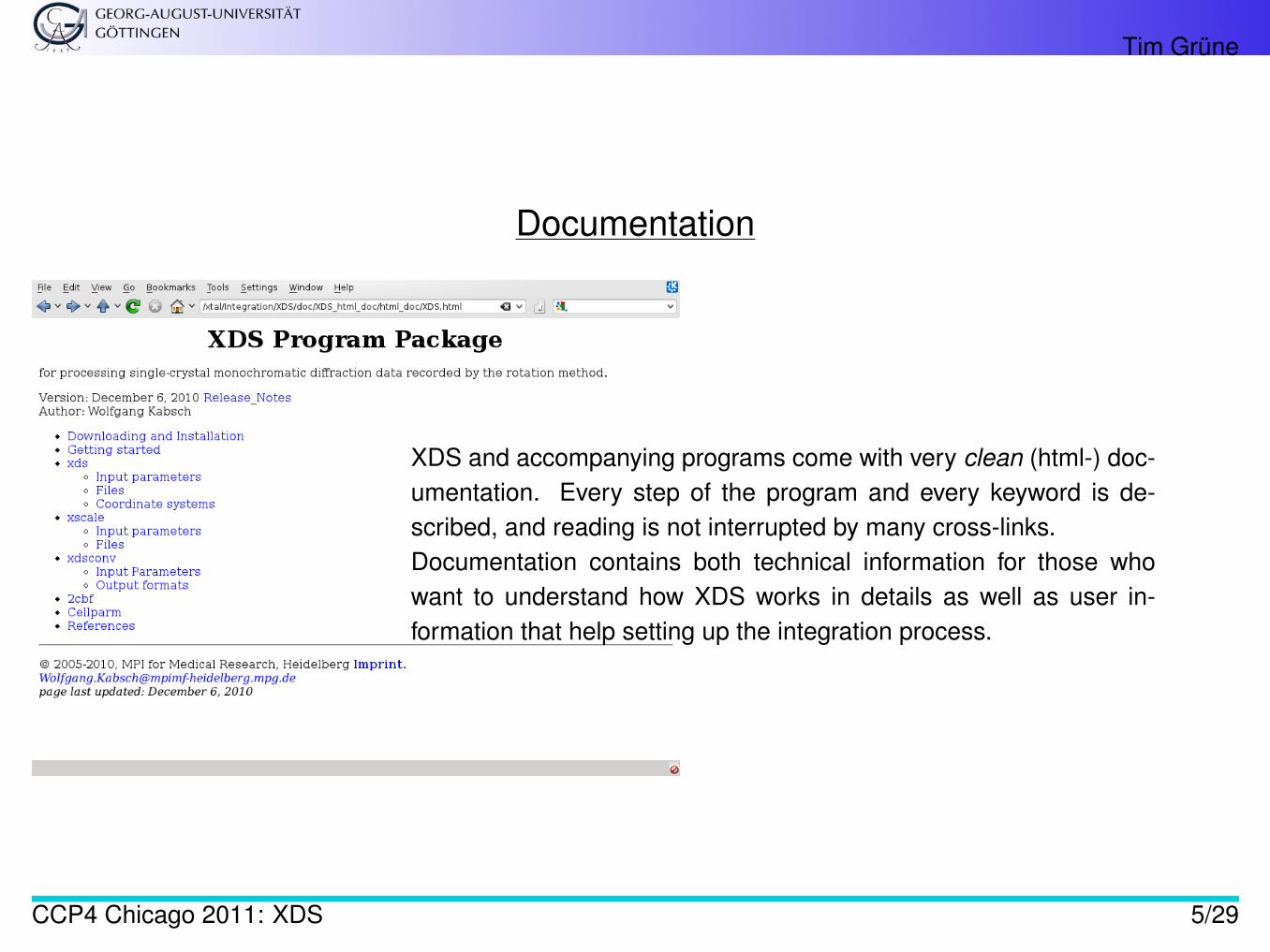
XDS and accompanying programs come with very clean (html-) doc-umentation. Every step of the program and every keyword is de-scribed, and reading is not interrupted by many cross-links.Documentation contains both technical information for those whowant to understand how XDS works in details as well as user in-formation that help setting up the integration process.
CCP4 Chicago 2011: XDS 5/29
Tim Grüne
Other Sources of Information
Wiki http://strucbio.biologie.uni-konstanz.de/xdswiki/ Tips, tricks, tutorials,. . .CCP4bb Sign up at www.ccp4.ac.uk
CCP4 Chicago 2011: XDS 6/29

Tim Grüne
Templates
• Templates of input scripts for all sup-ported detector formats• Only very few adjustments necessary to
get started• Beamlines often generate appropriate in-
put scripts• generate XDS.INP from XDSwiki for
MARCCD, ADSC, and TODO
CCP4 Chicago 2011: XDS 7/29
Tim Grüne
XDS.INP
XDS is controlled by one single input file: XDS.INP.
• Name cannot be changed• Each data set must be run in separate directory to avoid overwriting of files.• Contains about 100 Keywords a of the form
KEYWORD=VALUE
• Only about 10 Keywords must be modified for most data sets (e.g. image names, detectordistance, number of images, etc.)• Most important one:
JOB= XYCORR INIT COLSPOT IDXREF DEFPIX XPLAN INTEGRATE CORRECT
Each name stands for one of the steps XDS carries out during data integration.(XPLAN is optional and corresponds to the BEST [2] or STRATEGY [1] output to report optimaldata collection range(s))
aalso called “cards” for historical reasons
CCP4 Chicago 2011: XDS 8/29
Tim Grüne
The Steps
XYINIT writes files for positional corrections of the detector plane. Most modern detectors providealready corrected images so that these to files are normally flat.
INIT determines initial detector backgroundIDXREF indexing: unit cell dimensions and crystal orientationDEFPIX set active dectector area (exclude resolution cut-off, beam stop shadow, . . . )(XPLAN, optional) generate “strategy” table with data completeness depending on
• starting angle• total scan width
INTEGRATE determine reflection intensitiesCORRECT applies corrections (polarisation, Lorentz-correction, . . . ), scales reflections, reports data
statistics
CCP4 Chicago 2011: XDS 9/29
Tim Grüne
Program Flow
• Each step must be passed at least once - the subsequent steps depend on files produced bythe previous steps.• Each step creates a log-file (XYINIT.LP, INIT.LP,...).• IDXREF is the main hurdle - once unit cell and crystal orientation are determined, integration
usually runs smoothly.• CORRECT summarises the quality of the data.• Mostly IDXREF.LP and CORRECT.LP should be inspected.
CCP4 Chicago 2011: XDS 10/29
Tim Grüne
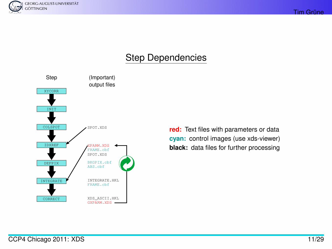
Step Dependencies
IDXREF
COLSPOT
INIT
XYCORR
CORRECT
INTEGRATE
DEFPIX
XPARM.XDS
INTEGRATE.HKL
XDS_ASCII.HKL
GXPARM.XDS
BKGPIX.cbf
ABS.cbf
FRAME.cbf
FRAME.cbf
Step (Important)
output files
SPOT.XDS
SPOT.XDS
red: Text files with parameters or datacyan: control images (use xds-viewer)black: data files for further processing
CCP4 Chicago 2011: XDS 11/29
Tim Grüne
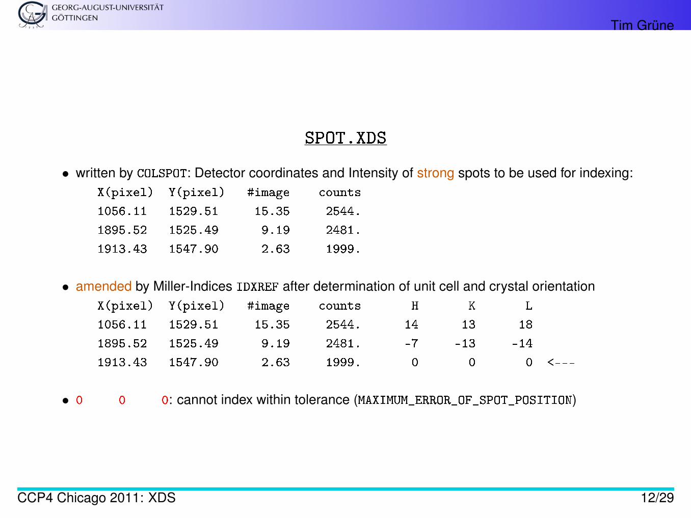
SPOT.XDS
• written by COLSPOT: Detector coordinates and Intensity of strong spots to be used for indexing:X(pixel) Y(pixel) #image counts
1056.11 1529.51 15.35 2544.
1895.52 1525.49 9.19 2481.
1913.43 1547.90 2.63 1999.
• amended by Miller-Indices IDXREF after determination of unit cell and crystal orientationX(pixel) Y(pixel) #image counts H K L
1056.11 1529.51 15.35 2544. 14 13 18
1895.52 1525.49 9.19 2481. -7 -13 -14
1913.43 1547.90 2.63 1999. 0 0 0 <---
• 0 0 0: cannot index within tolerance (MAXIMUM_ERROR_OF_SPOT_POSITION)
CCP4 Chicago 2011: XDS 12/29
Tim Grüne
“!!! ERROR !!! SOLUTION IS INACCURATE”
Correct indexing is crucial for data integration. If XDS cannot index more than 70 % of all reflections listed inSPOT.XDS, it stops with the above error message.
Most common reasons:
1. Wrong ORGX, ORGY2. Poor data quality
XDS has a very robust indexing method and depending on the situation, one can usually continue integrationby one or a combination of the following means.
CCP4 Chicago 2011: XDS 13/29
Tim Grüne
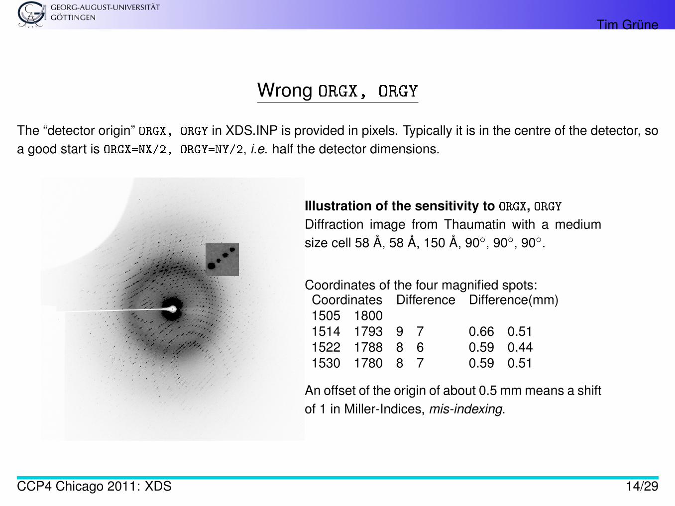
Wrong ORGX, ORGY
The “detector origin” ORGX, ORGY in XDS.INP is provided in pixels. Typically it is in the centre of the detector, soa good start is ORGX=NX/2, ORGY=NY/2, i.e. half the detector dimensions.
Illustration of the sensitivity to ORGX, ORGYDiffraction image from Thaumatin with a mediumsize cell 58 Å, 58 Å, 150 Å, 90◦, 90◦, 90◦.
Coordinates of the four magnified spots:Coordinates Difference Difference(mm)1505 18001514 1793 9 7 0.66 0.511522 1788 8 6 0.59 0.441530 1780 8 7 0.59 0.51
An offset of the origin of about 0.5 mm means a shiftof 1 in Miller-Indices, mis-indexing.
CCP4 Chicago 2011: XDS 14/29
Tim Grüne
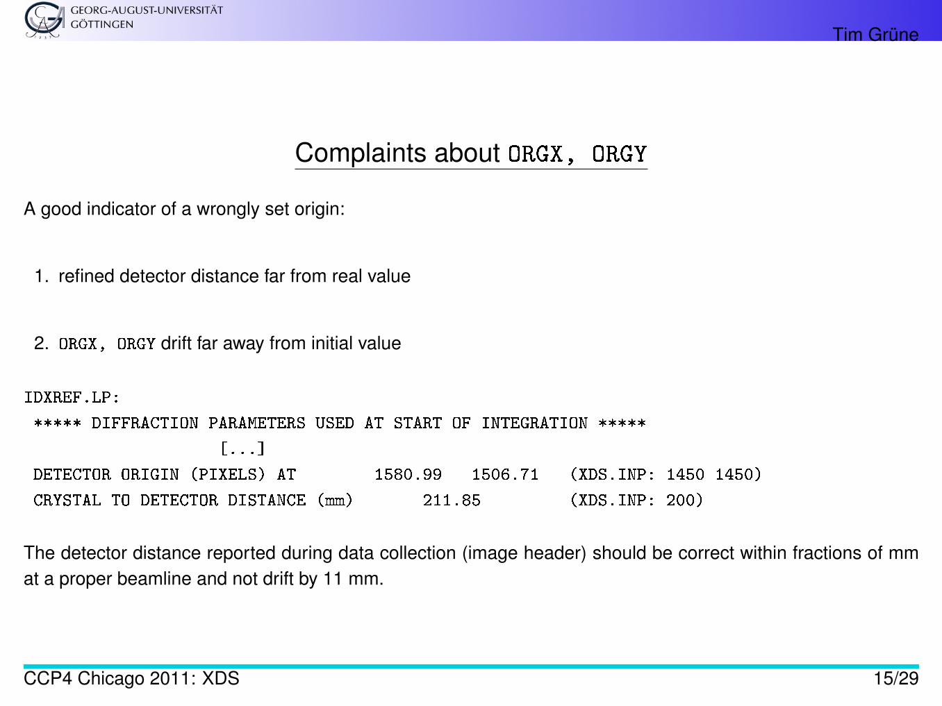
Complaints about ORGX, ORGY
A good indicator of a wrongly set origin:
1. refined detector distance far from real value
2. ORGX, ORGY drift far away from initial value
IDXREF.LP:
***** DIFFRACTION PARAMETERS USED AT START OF INTEGRATION *****
[...]
DETECTOR ORIGIN (PIXELS) AT 1580.99 1506.71 (XDS.INP: 1450 1450)
CRYSTAL TO DETECTOR DISTANCE (mm) 211.85 (XDS.INP: 200)
The detector distance reported during data collection (image header) should be correct within fractions of mmat a proper beamline and not drift by 11 mm.
CCP4 Chicago 2011: XDS 15/29
Tim Grüne
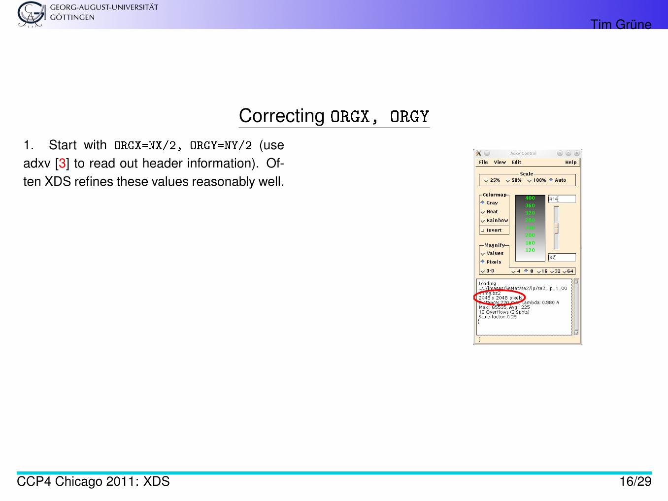
Correcting ORGX, ORGY
1. Start with ORGX=NX/2, ORGY=NY/2 (useadxv [3] to read out header information). Of-ten XDS refines these values reasonably well.
CCP4 Chicago 2011: XDS 16/29
Tim Grüne
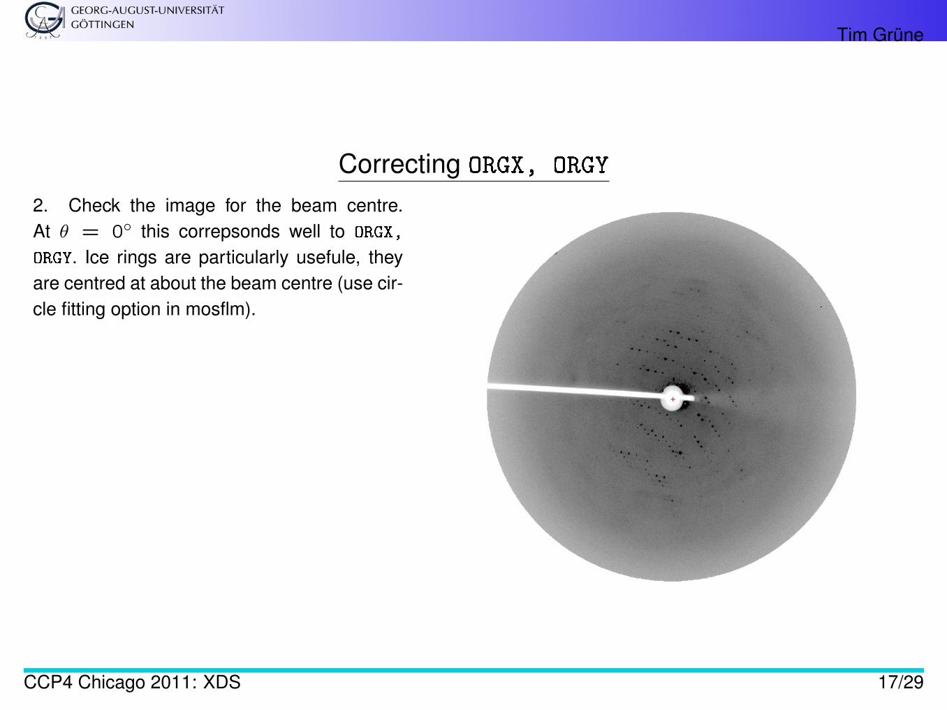
Correcting ORGX, ORGY
2. Check the image for the beam centre.At θ = 0◦ this correpsonds well to ORGX,
ORGY. Ice rings are particularly usefule, theyare centred at about the beam centre (use cir-cle fitting option in mosflm).
CCP4 Chicago 2011: XDS 17/29
Tim Grüne
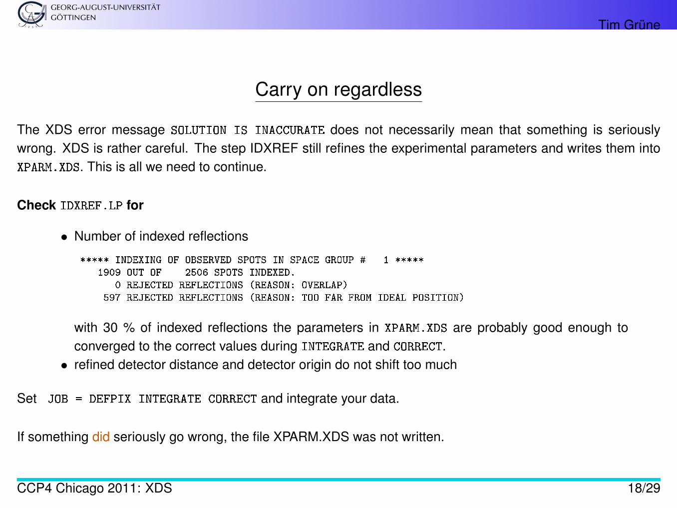
Carry on regardless
The XDS error message SOLUTION IS INACCURATE does not necessarily mean that something is seriouslywrong. XDS is rather careful. The step IDXREF still refines the experimental parameters and writes them intoXPARM.XDS. This is all we need to continue.
Check IDXREF.LP for
• Number of indexed reflections
***** INDEXING OF OBSERVED SPOTS IN SPACE GROUP # 1 *****1909 OUT OF 2506 SPOTS INDEXED.
0 REJECTED REFLECTIONS (REASON: OVERLAP)597 REJECTED REFLECTIONS (REASON: TOO FAR FROM IDEAL POSITION)
with 30 % of indexed reflections the parameters in XPARM.XDS are probably good enough toconverged to the correct values during INTEGRATE and CORRECT.• refined detector distance and detector origin do not shift too much
Set JOB = DEFPIX INTEGRATE CORRECT and integrate your data.
If something did seriously go wrong, the file XPARM.XDS was not written.
CCP4 Chicago 2011: XDS 18/29
Tim Grüne
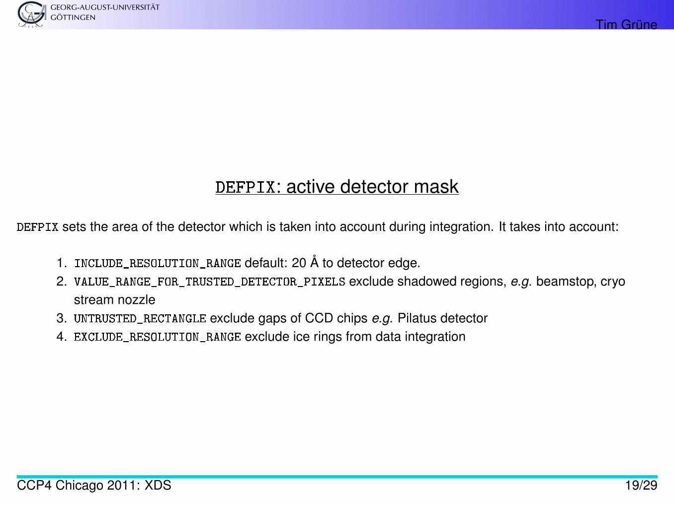
DEFPIX: active detector mask
DEFPIX sets the area of the detector which is taken into account during integration. It takes into account:
1. INCLUDE_RESOLUTION_RANGE default: 20 Å to detector edge.2. VALUE_RANGE_FOR_TRUSTED_DETECTOR_PIXELS exclude shadowed regions, e.g. beamstop, cryo
stream nozzle3. UNTRUSTED_RECTANGLE exclude gaps of CCD chips e.g. Pilatus detector4. EXCLUDE_RESOLUTION_RANGE exclude ice rings from data integration
CCP4 Chicago 2011: XDS 19/29
Tim Grüne
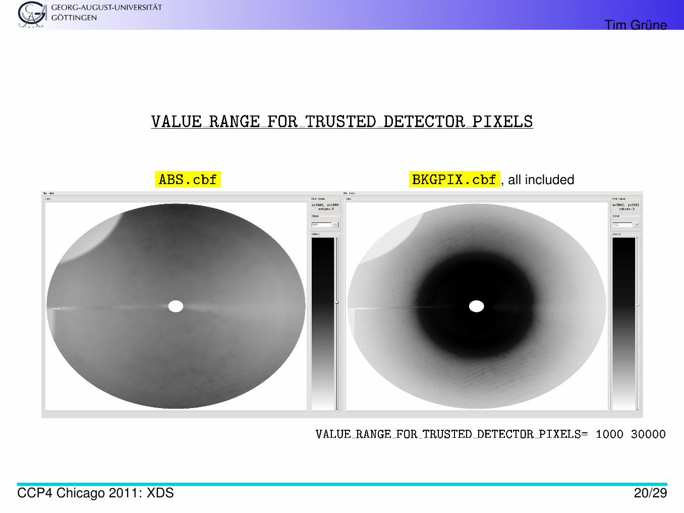
VALUE RANGE FOR TRUSTED DETECTOR PIXELS
ABS.cbf BKGPIX.cbf , all included
VALUE RANGE FOR TRUSTED DETECTOR PIXELS= 1000 30000
CCP4 Chicago 2011: XDS 20/29
Tim Grüne
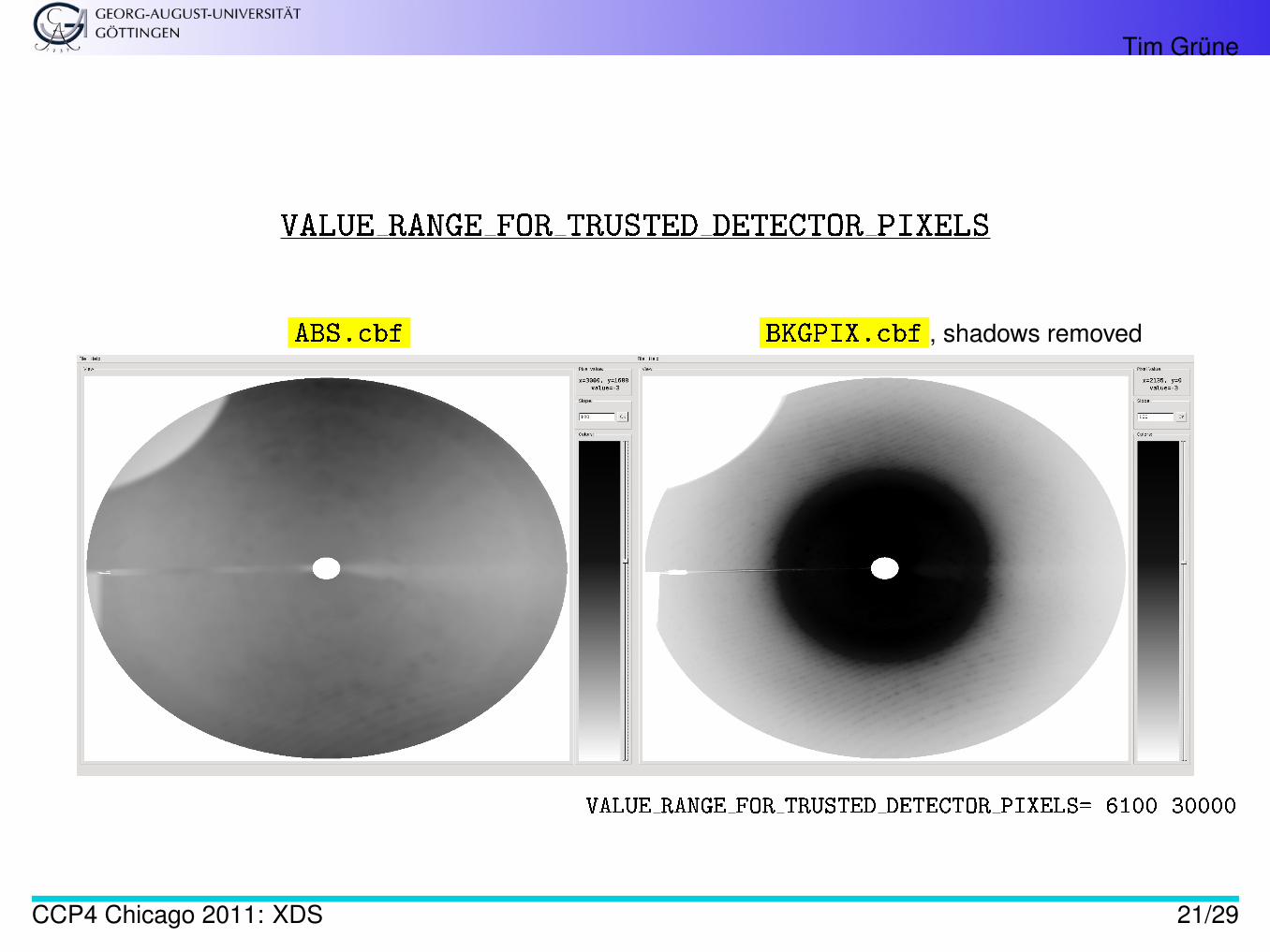
VALUE RANGE FOR TRUSTED DETECTOR PIXELS
ABS.cbf BKGPIX.cbf , shadows removed
VALUE RANGE FOR TRUSTED DETECTOR PIXELS= 6100 30000
CCP4 Chicago 2011: XDS 21/29
Tim Grüne
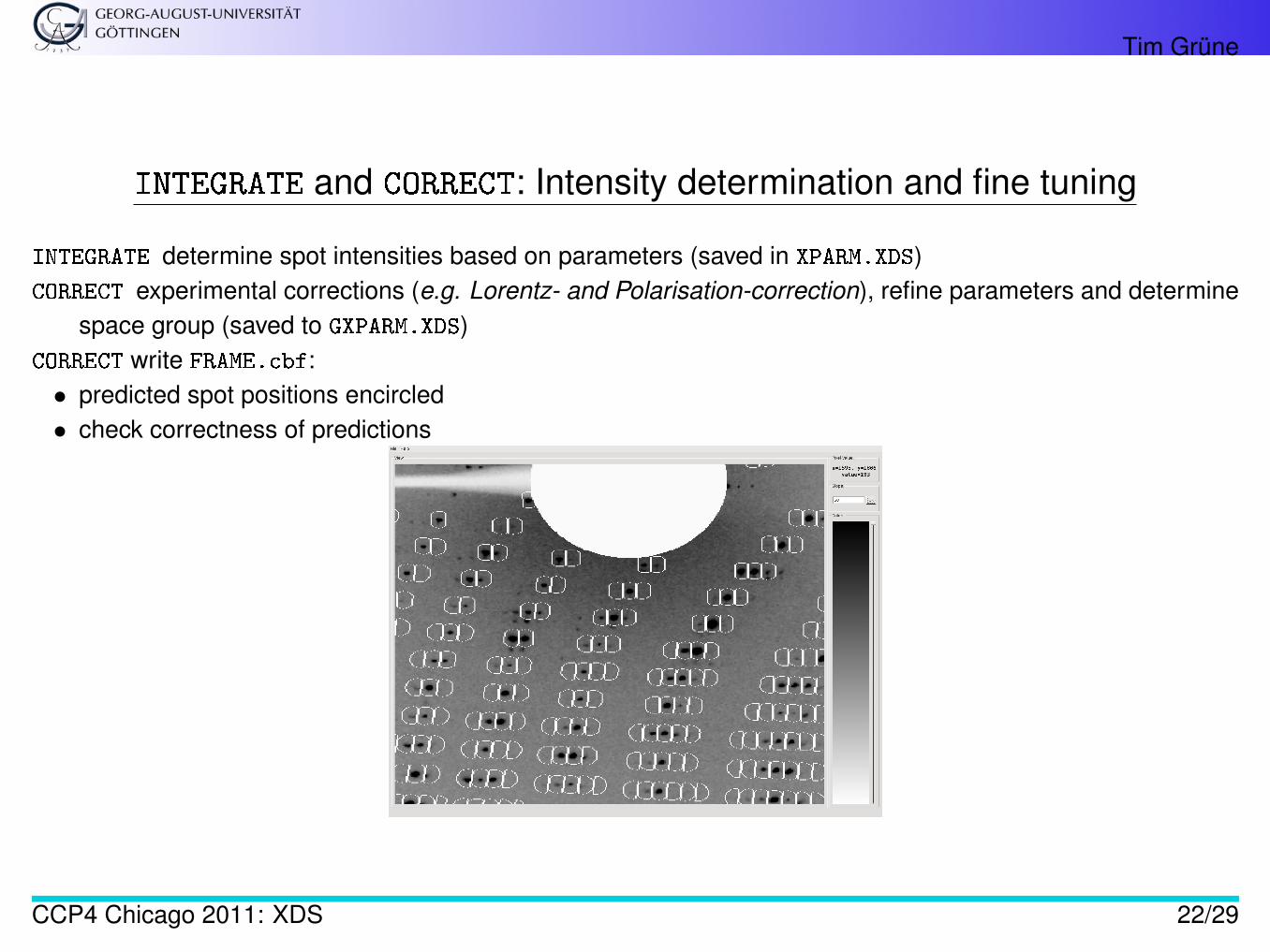
INTEGRATE and CORRECT: Intensity determination and fine tuning
INTEGRATE determine spot intensities based on parameters (saved in XPARM.XDS)CORRECT experimental corrections (e.g. Lorentz- and Polarisation-correction), refine parameters and determine
space group (saved to GXPARM.XDS)CORRECT write FRAME.cbf:• predicted spot positions encircled• check correctness of predictions
CCP4 Chicago 2011: XDS 22/29
Tim Grüne
Recycling
• Parameters (in GXPARM.XDS) depend on measured intensities• Intensities (including corrections) depend on Parameters⇒ rename GXPARM.XDS to XPARM.XDS and rerun XDS (JOB = DEFPIX INTEGRATE CORRECT) to im-
prove results.
This way one should also set the correct high- and low- resolution cut-offs
CCP4 Chicago 2011: XDS 23/29
Tim Grüne
Resolution Cut-Off
The default resolution range in XDS is 20 Å to the detector edge
INCLUDE_RESOLUTION_RANGE=20.0 0.0
• Medium to low resolution data: increase 20 Å to 30 Å or even 50 Å (check BKGPIX.cbf)• After second round of integration: determine high-resolution cut-off. My favourite: xprep - higher
number of resolution shells than e.g. listed in CORRECT.LP
Why after second round?
• Correct space group rather than P1
⇒ more symmetry related reflections⇒ more reliable data statistics, especially I/σI
CCP4 Chicago 2011: XDS 24/29
Tim Grüne
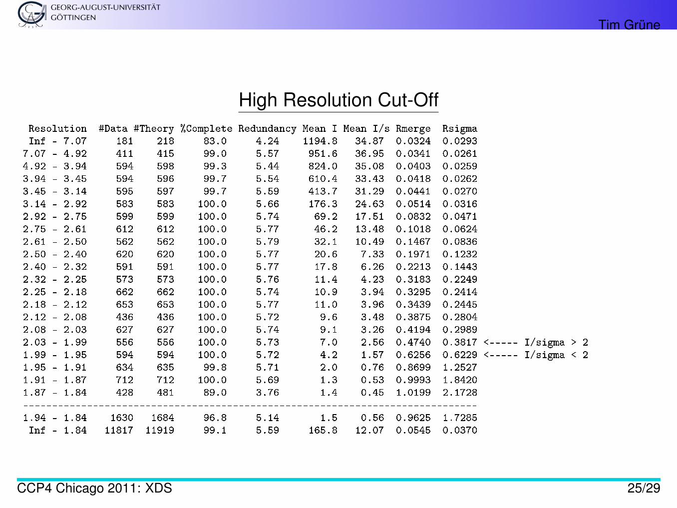
High Resolution Cut-OffResolution #Data #Theory %Complete Redundancy Mean I Mean I/s Rmerge RsigmaInf - 7.07 181 218 83.0 4.24 1194.8 34.87 0.0324 0.02937.07 - 4.92 411 415 99.0 5.57 951.6 36.95 0.0341 0.02614.92 - 3.94 594 598 99.3 5.44 824.0 35.08 0.0403 0.02593.94 - 3.45 594 596 99.7 5.54 610.4 33.43 0.0418 0.02623.45 - 3.14 595 597 99.7 5.59 413.7 31.29 0.0441 0.02703.14 - 2.92 583 583 100.0 5.66 176.3 24.63 0.0514 0.03162.92 - 2.75 599 599 100.0 5.74 69.2 17.51 0.0832 0.04712.75 - 2.61 612 612 100.0 5.77 46.2 13.48 0.1018 0.06242.61 - 2.50 562 562 100.0 5.79 32.1 10.49 0.1467 0.08362.50 - 2.40 620 620 100.0 5.77 20.6 7.33 0.1971 0.12322.40 - 2.32 591 591 100.0 5.77 17.8 6.26 0.2213 0.14432.32 - 2.25 573 573 100.0 5.76 11.4 4.23 0.3183 0.22492.25 - 2.18 662 662 100.0 5.74 10.9 3.94 0.3295 0.24142.18 - 2.12 653 653 100.0 5.77 11.0 3.96 0.3439 0.24452.12 - 2.08 436 436 100.0 5.72 9.6 3.48 0.3875 0.28042.08 - 2.03 627 627 100.0 5.74 9.1 3.26 0.4194 0.29892.03 - 1.99 556 556 100.0 5.73 7.0 2.56 0.4740 0.3817 <----- I/sigma > 21.99 - 1.95 594 594 100.0 5.72 4.2 1.57 0.6256 0.6229 <----- I/sigma < 21.95 - 1.91 634 635 99.8 5.71 2.0 0.76 0.8699 1.25271.91 - 1.87 712 712 100.0 5.69 1.3 0.53 0.9993 1.84201.87 - 1.84 428 481 89.0 3.76 1.4 0.45 1.0199 2.1728------------------------------------------------------------------------------1.94 - 1.84 1630 1684 96.8 5.14 1.5 0.56 0.9625 1.7285Inf - 1.84 11817 11919 99.1 5.59 165.8 12.07 0.0545 0.0370
CCP4 Chicago 2011: XDS 25/29
Tim Grüne
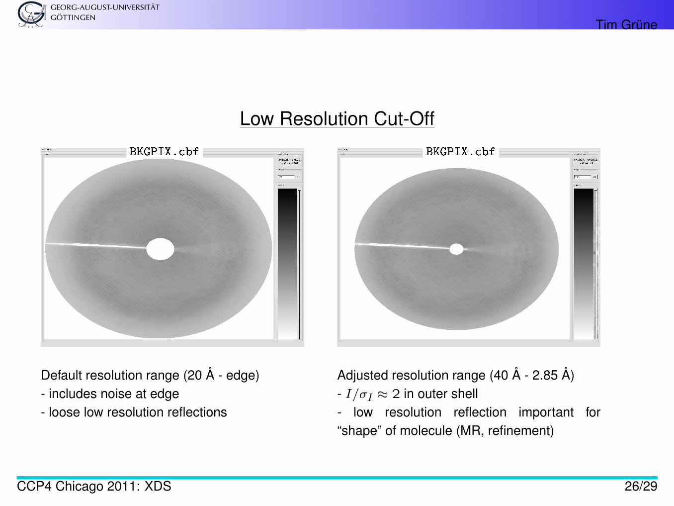
Low Resolution Cut-Off
BKGPIX.cbf BKGPIX.cbf
Default resolution range (20 Å - edge)- includes noise at edge- loose low resolution reflections
Adjusted resolution range (40 Å - 2.85 Å)- I/σI ≈ 2 in outer shell- low resolution reflection important for“shape” of molecule (MR, refinement)
CCP4 Chicago 2011: XDS 26/29
Tim Grüne
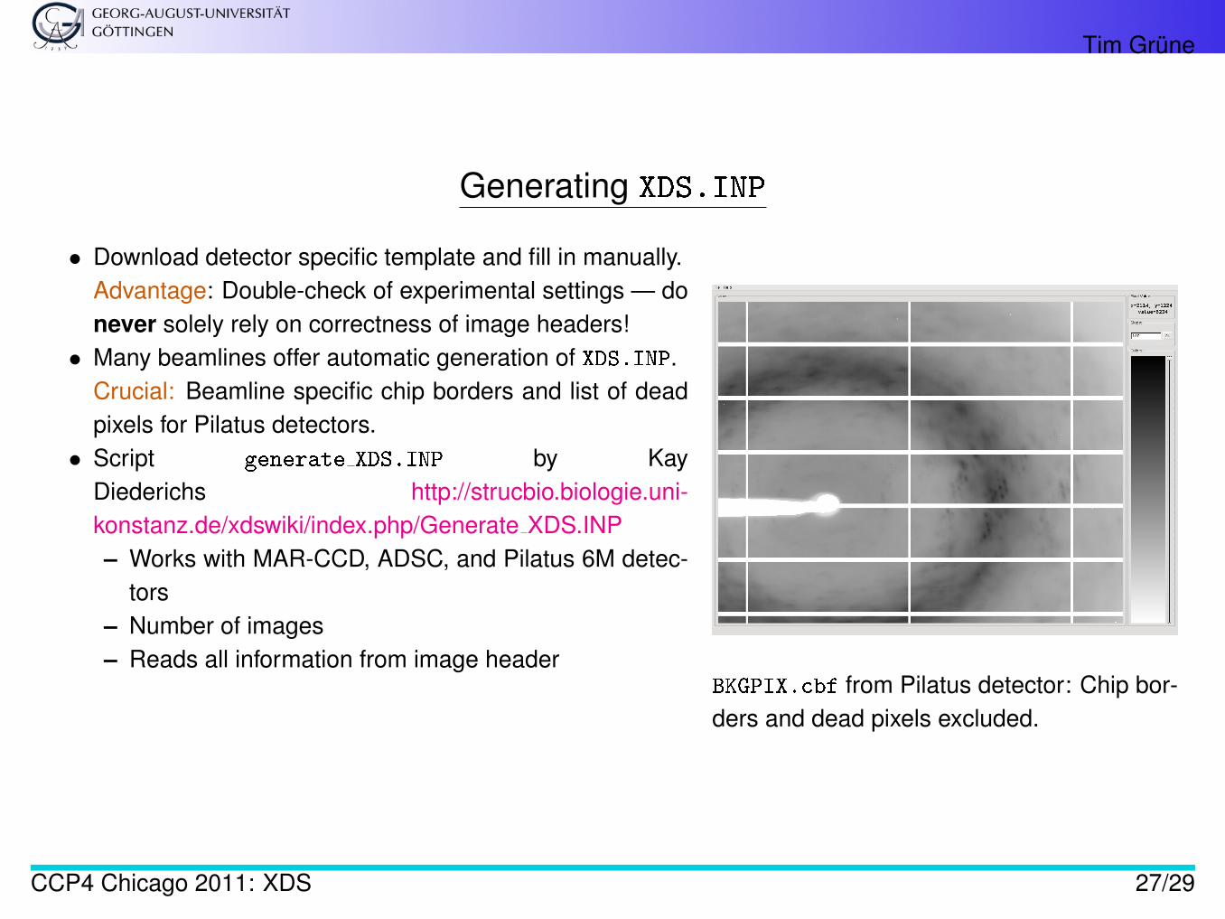
Generating XDS.INP
• Download detector specific template and fill in manually.Advantage: Double-check of experimental settings — donever solely rely on correctness of image headers!• Many beamlines offer automatic generation of XDS.INP.
Crucial: Beamline specific chip borders and list of deadpixels for Pilatus detectors.• Script generate XDS.INP by Kay
Diederichs http://strucbio.biologie.uni-konstanz.de/xdswiki/index.php/Generate XDS.INP– Works with MAR-CCD, ADSC, and Pilatus 6M detec-
tors– Number of images– Reads all information from image header
BKGPIX.cbf from Pilatus detector: Chip bor-ders and dead pixels excluded.
CCP4 Chicago 2011: XDS 27/29
Tim Grüne
XDSSTAT
The program XDSSTAT (Kay Diederichs, also from the XDS Wiki) creates more detailed statistics from XDSintegration.
The output can be viewed with a file browser - similar tables like scala output.
General rule of thumb: developers like encouragment — if you miss a feature point it out to the program authorto increase the chance of the feature being incorporated
(One of the most efficient “examples”: Paul Emsley & Bernd Lohkamp (Coot), Pavel Afonine (phenix)).
CCP4 Chicago 2011: XDS 28/29
Tim Grüne
References
1. Leslie, A.G.W., Recent changes to the MOSFLM package for processing film and image plate data,Joint CCP4 + ESF-EAMCB Newsletter on Protein Crystallography (1992), No. 26
2. A.N. Popov and Bourenkov , Choice of data-collection parameters based on statistic modeling ActaCrystallogr. (2003). D59, 1145-1153
3. Andrew Arvai, http://www.scripps.edu/˜arvai/adxv.html
CCP4 Chicago 2011: XDS 29/29