Embed Size (px)
Citation preview
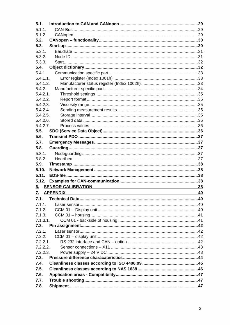
CCM 01 - Set Contamination Control Monitor
Instruction manual Version 2.7
Serial no. CCM 01: ..................
Serial no. PFS 01: ..................
Version valid from: 22.08.2016
2
Index Seite 1. SAFETY INFORMATION 4
1.1. Dangers of maloperation ................................................................................... 4
1.2. Intended applications ........................................................................................ 4
2. OPERATION AND INSTALLATION 5
2.1. Setup ................................................................................................................... 5
2.1.1. Block diagram .................................................................................................. 5 2.2. General information ........................................................................................... 6
2.3. Measuring principle of the PFS 01 (Particle Flow Sensor) .............................. 6
2.4. Sensor installation ............................................................................................. 7
2.5. Optimum operating conditions ......................................................................... 7
2.6. Installation of the display unit CCM 01 ............................................................. 7
2.7. Electrical connection of the PFS 01 and the CCM 01 ...................................... 7
2.8. Operating the CCM 01 software ...................................................................... 10
2.8.1. Control keys................................................................................................... 10 2.8.2. Menu structure ............................................................................................... 11 2.8.3. Main menu ..................................................................................................... 12 2.8.3.1. Measure .................................................................................................... 12 2.8.3.1.1. Viscosity Range .................................................................................... 12 2.8.3.1.2. Report Format (ISO 4406 or NAS 1638) ............................................... 12 2.8.3.1.3. Start ...................................................................................................... 13 2.8.3.1.4. Storage Interval .................................................................................... 13 2.8.3.2. Data Manager ........................................................................................... 14 2.8.3.2.1. Transfer Data ....................................................................................... 14 2.8.3.2.1.1. Data transfer by using the RS232 - interface .................................... 14
2.8.3.2.1.2. Data transfer by using the external printer ........................................ 15
2.8.3.2.2. Delete Data .......................................................................................... 15 2.8.3.2.3. Stored Data .......................................................................................... 15 2.8.3.3. Options ..................................................................................................... 15 2.8.3.3.1. Limits .................................................................................................... 16 2.8.3.3.2. Set Time ............................................................................................... 17 2.8.3.3.3. Calibration ............................................................................................ 17 2.8.3.3.4. CAN ...................................................................................................... 18 3. DATA TRANSFER 18
3.1. Connection to an external computer as an evaluation device ...................... 19
3.1.1. Connection via RS232 – interface .................................................................. 19 3.1.2. Connection of the RS232 – adaptor plug into the interface ............................ 19 3.1.3. Connection of the Bluetooth modul EBT 01 ................................................... 19 3.2. Continuous data transfer of the actual measurements ................................. 19
3.2.1. HyperTerminal ............................................................................................... 19 3.2.2. Setup of HyperTerminal ................................................................................. 20 3.2.3. Procedure ...................................................................................................... 21 3.2.4. Protocol for the contiuous data transfer ......................................................... 21 3.3. Data transfer of the saved measurements ..................................................... 22
3.3.1. Export and evaluation of the stored data via “CCM 01 data manager Vers. 2.0”22 3.3.2. One-time program installation ........................................................................ 22 3.3.3. Procedure ...................................................................................................... 23 4. EVALUATING MEASUREMENTS 28
5. CAN INTERFACE 29
3
5.1. Introduction to CAN and CANopen ................................................................. 29
5.1.1. CAN-Bus ....................................................................................................... 29 5.1.2. CANopen ....................................................................................................... 29 5.2. CANopen – functionality .................................................................................. 30
5.3. Start-up ............................................................................................................. 30
5.3.1. Baudrate ........................................................................................................ 31 5.3.2. Node ID ......................................................................................................... 31 5.3.3. Start ............................................................................................................... 32 5.4. Object dictionary .............................................................................................. 32
5.4.1. Communication specific part .......................................................................... 33 5.4.1.1. Error register (Index 1001h) ...................................................................... 33 5.4.1.2. Manufacturer status register (Index 1002h) ............................................... 33 5.4.2. Manufacturer specific part.............................................................................. 34 5.4.2.1. Threshold settings ..................................................................................... 35 5.4.2.2. Report format ............................................................................................ 35 5.4.2.3. Viscosity range .......................................................................................... 35 5.4.2.4. Sending measurement results ................................................................... 35 5.4.2.5. Storage interval ......................................................................................... 35 5.4.2.6. Stored data ............................................................................................... 35 5.4.2.7. Process values .......................................................................................... 36 5.5. SDO (Service Data Object) ............................................................................... 36
5.6. Transmit PDO ................................................................................................... 37
5.7. Emergency Messages ...................................................................................... 37
5.8. Guarding ........................................................................................................... 37
5.8.1. Nodeguarding ................................................................................................ 37 5.8.2. Heartbeat ....................................................................................................... 37 5.9. Timestamp ........................................................................................................ 38
5.10. Network Management ...................................................................................... 38
5.11. EDS-file ............................................................................................................. 38
5.12. Examples for CAN-communication ................................................................. 38
6. SENSOR CALIBRATION 38
7. APPENDIX 40
7.1. Technical Data .................................................................................................. 40
7.1.1. Laser sensor .................................................................................................. 40 7.1.2. CCM 01 – Display unit ................................................................................... 40 7.1.3. CCM 01 – housing ......................................................................................... 41 7.1.3.1. CCM 01 - backside of housing .................................................................. 41 7.2. Pin assignment ................................................................................................. 42
7.2.1. Laser sensor .................................................................................................. 42 7.2.2. CCM 01 – display unit .................................................................................... 42 7.2.2.1. RS 232 interface and CAN – option .......................................................... 42 7.2.2.2. Sensor connections – X11 ........................................................................ 43 7.2.2.3. Power supply – 24 V DC ........................................................................... 43 7.3. Pressure difference characateristics .............................................................. 44
7.4. Cleanliness classes according to ISO 4406:99 .............................................. 45
7.5. Cleanliness classes according to NAS 1638 .................................................. 46
7.6. Application areas - Compatibility .................................................................... 47
7.7. Trouble shooting .............................................................................................. 47
7.8. Shipment ........................................................................................................... 47

4
1. Safety information
1.1. Dangers of maloperation The CCM 01 underwent a safety inspection according to IEC 1010-1/ EN 61010 – 1, part 1. Integrated hydraulic and electronic safety elements ensure safe operation if the device is used as it was intended. In case of maloperation or abuse, as well as in case of insensitivity for application limits and safety regulations, the following threats can occur for:
Life or physical condition of the operator,
the CCM 01, as well as connected machines and systems connected,
the accuracy of measurements of the CCM 01,
the environment. This manual does contain information and safety advice, which ensure risk free operations and which help to keep the device in an ideal condition. Therefore, it is necessary that everybody having to do with the operation and maintenance of the unit strictly follows this instruction manual.
1.2. Intended applications The CCM 01 – Set is an efficient and robust inline diagnostic measuring system for determining the contamination classes according to ISO 4406:99 and NAS 1638. It works very reliably and does fulfil all requirements of daily measurements. The set is intended and tested to operate with all usual hydraulic and gear fluids as well as synthetic esters. Application limits: Maximum acceptable operating pressure: 50 bar / 725 psi Maximum oil temperature: 70 °C / 158 °F Viscosity range: 10...400 mm²/s / 46...1854 SUS Miniumum volume flow: 500 ml/ min / 0,132 gal/ min Maximum acceptable volume flow: 50 l/min / 13 gal/min Generally, the CCM 01 – Set has to be operated with 24 V DC (ripple: < 300 mVpp)!

5
2. Operation and installation
2.1. Setup The CCM 01 – Set consists of the PFS 01 (Particle Flow rate Sensor), a cable to connect the sensor (l = 5 m) and the CCM 01 – display unit.
A PFS 01 belongs always to a specific CCM 01. The calibration values of the PFS 01 are stored always in the respective CCM 01!
2.1.1. Block diagram

6
2.2. General information The effects of contamination on hydraulic or lubricating systems are manifold. It causes significantly increased wear, increased risk of component failure as well as malfunctions. The CCM 01 - set fulfils all necessary requirements for continuous monitoring and analysis of hydraulic systems and test stands. It is an inexpensive stationary monitoring solution. The CCM 01 has the following functions:
- Automatic particle counting and display of the measuring results acc. to contamination classes ISO 4406 or NAS 1638 every 20 seconds.
- Storage of 100 measured data in selectable storage intervals. - Transmission of the current measuring results via RS 232 interface. - 4 programmable contamination limit values with 4 potential free relay contacts. When
exceeding the limit value the appropriate relay contacts closes – thus allowing control functions in the hydraulic and lubrication system, which has to be observed.
- Transmission of the stored measured data on an external cpmputer in a Windows Excel
file. The CCM 01 – Set should only be switched on when the PFS 01 is flown through with oil, because there is installed a thermic volume flow sensor. Very long runnning times without flow rate can cause damages!
2.3. Measuring principle of the PFS 01 (Particle Flow Sensor)
The PFS 01 consists of two sensor elements: Laser sensor for particle counting and flow sensor for measuring the volume flow in the measuring channel.
The PFS 01 operates based on the offline flow principle: Using a counter balance valve, a partial flow of the oil flowing trough the device is lead through the flow sensor and the laser particle counting sensor in order to analyze.
The counted particles per volume and the particle concentrations for these following particle sizes are determined: > 4 µm (c) , > 6 µm(c), > 14 µm(c), > 21 µm(c) or > 6,4 µm(c), > 14 µm(c), > 21 µm(c), > 37 µm(c) (switchable). Results can be displayed according to ISO 4406 respectively NAS 1638.
The sensor integrated in the PFS operates based on the light blockade principle and it is calibrated with ISO MDT according to ISO 11171.

7
2.4. Sensor installation
Integrate the PFS 01 in the hydraulic system (Connection: Thread according to ISO 228-G1 or ¾”).
The sensor should be installed and flown through vertically if possible. Optimal, from bottom to top to avoid air inclusions respectively to dissolve them fastly.
The assembly should be vibration-cushioned and the connection should be made with hoses.
The installation should not be directly on vibrated components or motors.
2.5. Optimum operating conditions
If there are very fine air bubbles in the oil, there is the possibility that these air bubbles are counted as particles. With a measurement under pressure (40 bar), a suppression of air bubbles is reached.
There is another variant of the PFS 01 sensor. With this variant only the measuring channel of the sensor is flown through. For this variant a constant volume flow of 30 – 100 ml/min must be provided.
At very low viscosities (10 – 20 mm²/s) there should be installed a more weak spring in the bypass valve and the total volume flow through the sensor should not be higher than 20 l/min.
2.6. Installation of the display unit CCM 01
Mount the CCM 01 display unit to the system. (see chapter 7.1.3.1)
2.7. Electrical connection of the PFS 01 and the CCM 01
Connect the display unit with the sensor using the cable. Extend the sensor cable after consultation with the manufacturer only.
Connect the 24 V power cable and the CCM 01 display unit.
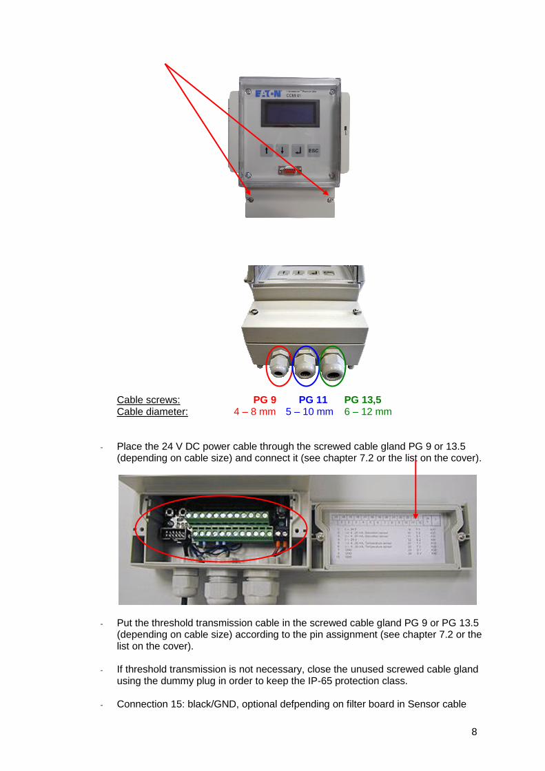
Loose screws and remove cover.
8
Cable screws: PG 9 PG 11 PG 13,5 Cable diameter: 4 – 8 mm 5 – 10 mm 6 – 12 mm
- Place the 24 V DC power cable through the screwed cable gland PG 9 or 13.5 (depending on cable size) and connect it (see chapter 7.2 or the list on the cover).
- Put the threshold transmission cable in the screwed cable gland PG 9 or PG 13.5
(depending on cable size) according to the pin assignment (see chapter 7.2 or the list on the cover).
- If threshold transmission is not necessary, close the unused screwed cable gland
using the dummy plug in order to keep the IP-65 protection class.
- Connection 15: black/GND, optional defpending on filter board in Sensor cable

9
The CCM 01 set is ready for operation, if the laser sensor, the power cable and the threshold transmission cable are connected to the CCM 01 display unit.

10
2.8. Operating the CCM 01 software
After the sensor has been entered into the hydraulic system, considering all application limits, start the CCM 01.
Wait through the welcome screen until the main menu is being displayed. It can be operated using the control keys.
2.8.1. Control keys
Menu controls Enter Back (Escape)

11
2.8.2. Menu structure
The menu structure consists of three levels (plus start screen), the first both levels serve only navigation for the third level from which the single set options and measuring options can be started.
The following structure diagram shows the composition of menu navigations.
Transfer Data
Stored Data (display only)
Data Manager
Delete Data
Viscosity Range
Report Format
Measure
Start
Storage Intervall
CAN Baudrate
Start
CAN
CAN Node ID
Main Menu
Start Screen
Options
Set Limits
Set Time
Calibration

12
2.8.3. Main menu
Choose a submenu with the [ ] buttons.
The chosen item is marked with a * on the left side of the menu.
Enter the chosen menu item by hitting the [ ] button.
2.8.3.1. Measure Selection of the viscosity range, the using classification (ISO 4406 or NAS 1638) and start of the measuring.
Choose a submenu with the [ ] buttons.
The chosen item is marked with a * on the left side of the menu.
Enter the chosen menu item by hitting the [ ] button.
Use [ ESC ] to go back to the previous menu. (Display shows: )
2.8.3.1.1. Viscosity Range Selection of the viscosity range from used fluid allowing for the fluid temperature.
Use the [ ] buttons to choose the viscosity range.
The selected menu item will be marked with a * on the left side.
By hitting the [ ] button the selection of a viscosity range is confirmed.
You will automatically jump to the [ MEASURE ] menu.
2.8.3.1.2. Report Format (ISO 4406 or NAS 1638) Selection of the classification type (ISO 4406 or NAS 1638).
Use the [ ] buttons to select a classification.
The chosen classification is marked with a * on the left side of the menu.
By hitting [ ] the classification type is adopted and you will jump to the [ MEASURE ] menu automatically.

13
2.8.3.1.3. Start
Measurements are performed automatically and the results can be displayed as contamination classes. (depending upon selected classification type)
During the measuring the particles per counting channel and the volume flow constantly put out via the RS232 interface. (see chapter 3.2)
Serially, the CCM 01 comes with the data manager software. This software edits and
manages measurements stored by the CCM 01.
For this application a storage interval has to be selected. (see chapter 2.8.3.1.4)
Measurements will be stored continuously on the internal memory of the CCM 01 according to the selected storage interval. They can be transferred to an external computer using the RS232 interface or the Bluetooth modul EBT 01 in order to be edited and managed using the data manager software. (see chapter 3.3 )
Fixed limiting values are shown by a rectangle.
Exceeded limiting values are shown by a filled out rectangle in the display.
After disconnecting the power supply during the measurement it will automatically continue the measurement after reconnecting.
Measurements will be performed until the operator hits [ ESC ] and switches back to the [ MEASURE ] menu.
2.8.3.1.4. Storage Interval
Use the [ ] button to choose storage interval.
The intervals that can be chosen are between five minutes and seven days. Storing the set interval will occur in a battery backed RAM. In case of a power outage, the setting is saved.
100 measurements can be stored. After that, the oldest measurement is overwritten.
Chose the storage interval with the [ ] buttons and confirm by hitting the [ ] button – automatic return to the [ MEASURE ]– menu.
Use [ ESC ] to go back to the previous menu – changes will not be adopted.

14
2.8.3.2. Data Manager This submenu serves for transferring and deleting of the saved measurements.
Choose submenu with the [ ] buttons.
The chosen item is marked with a * on the left side of the menu.
Enter the chosen menu item by hitting the [ ] button.
Use [ ESC ] to go back to the previous menu. (Display shows: )
2.8.3.2.1. Transfer Data Data transfer of the stored measurements by using the RS232 interface or the external printer. (optional available at Eaton Technologies GmbH)
It is necessary to use a special printer with RS232 interface. .
Choose submenu with the [ ] buttons.
The chosen item is marked with a * on the left side of the menu.
Confirm by using the [ ] button.
Start of the data transfer.
2.8.3.2.1.1. Data transfer by using the RS232 - interface
After selecting the menu point „RS232“ a cyclic output of all saved measurements takes place via the RS232 - interface.
Every measurement is being transferred as a separate ASCII – streak.
Transferring will be performed until the operator ends it by hitting [ ESC ].
15
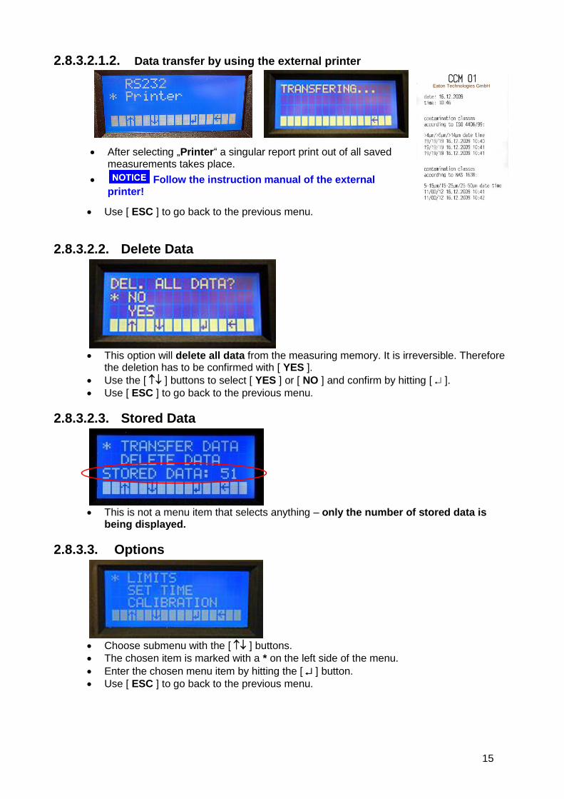
2.8.3.2.1.2. Data transfer by using the external printer
After selecting „Printer“ a singular report print out of all saved measurements takes place.
Follow the instruction manual of the external printer!
Use [ ESC ] to go back to the previous menu.
2.8.3.2.2. Delete Data
This option will delete all data from the measuring memory. It is irreversible. Therefore
the deletion has to be confirmed with [ YES ].
Use the [ ] buttons to select [ YES ] or [ NO ] and confirm by hitting [ ].
Use [ ESC ] to go back to the previous menu.
2.8.3.2.3. Stored Data
This is not a menu item that selects anything – only the number of stored data is
being displayed.
2.8.3.3. Options
Choose submenu with the [ ] buttons.
The chosen item is marked with a * on the left side of the menu.
Enter the chosen menu item by hitting the [ ] button.
Use [ ESC ] to go back to the previous menu.
Eaton Technologies GmbH

16
2.8.3.3.1. Limits When achieving or exceeding the set limit values in the measuring cycle the corresponding threshold contacts switch or rather close.
With the setting of zero values the functionality of the threshold contacts is switched off no switching or rather closing of the threshold contacts.
Threshold settings can be changed for each classification type and each counting channel.
These settings will also be stored in the back-up RAM.
Use the [ ] buttons to select the type of classification.
The selected type will be marked with a * on the left side of the menu.
Go to the selected classification type by hitting [ ]. Classification ISO 4406:99:
Use the [ ] buttons to choose the counting channel that has to be changed and
confirm by hitting [ ]. Use [ ] to set new contamination class threshold digit by digit
and confirm with [ ].
If new contamination class thresholds are set for all necessary counting channels use [ ESC ] to go back to the previous menu.
Classification NAS 1638:
Use the [ ] buttons to choose the counting channel that has to be changed and
confirm by hitting [ ].
Use [ ] to set new contamination class threshold digit by digit and
confirm with [ ].
If new contamination class thresholds are set for all necessary counting channels use [ ESC ] to go back to the previous menu.

17
2.8.3.3.2. Set Time
This function allows setting the real time clock that is integrated in the device.
Due to the back-up battery, the clock will keep running even if the power supply is shut off.
Day, month, year, hour and minute can be adjusted individually and they are being transmitted to the real time clock when the menu is being closed.
Select the parameter that has to be changed using the [ ] buttons.
The selected parameter is marked with a * on the left side of the menu.
By hitting the [ ] button, the position that has to be changed can be switched and
set a new parameter with the [ ] buttons.
Use [ ESC ] to go back to the previous menu.
2.8.3.3.3. Calibration As for all the other menus, every calibration value can be selected and changed
individually. Normally modifications are not necessary!
Since calibration values are of fundamental importance for measurements and should not be lost, they are saved as EEPROM. Calibration values will even be saved if the back-up battery is dead. They do not have to be re-entered.
Use the [ ] buttons to select the counting channel that is supposed to be changed.
Confirm by hitting the [ ] button.
The selected parameter will be marked with a * on the left side of the menu.

18
Select the digit that shall be changed by hitting the [ ] button and use the [ ]
buttons to set the new value.
Confirm by hitting the [ ] button.
Use [ ESC ] to go back to the previous menu. The calibration values can be taken from the provided calibration certificate.
2.8.3.3.4. CAN
Choose submenu with the [ ] buttons.
The chosen item is marked with a * on the left side of the menu.
Enter the chosen menu item by hitting the [ ] button.
Use [ ESC ] to go back to the previous menu. Detail informations and instructions see chapter 5 CAN interface
3. Data transfer
The data transfer from the CCM 01 to external computers is principle made by using the RS232 - interface. The data can be transferred with an interface cable as well as wirelessly with a Bluetooth modul.
During the measuring the counted particles per channel (≥ 4 µm(c), ≥ 6 µm(c), ≥14 µm(c), ≥ 21 µm(c) or ≥ 6,4 µm(c), ≥ 14 µm(c), ≥21 µm(c), ≥ 37 µm(c)) and the volume flow are available. They will be displayed on the external computer with a terminal program such as HyperTerminals from Microsoft. With the help of the CCM 01 data manager the stored measurements can be read and exported into an Excel table.

19
3.1. Connection to an external computer as an evaluation device
3.1.1. Connection via RS232 – interface
Connect the RS232 – connecting cable with the RS232 – interface on the frontplate
Connect the other side of the RS232 – connecting cable with the computer.
3.1.2. Connection of the RS232 – adaptor plug into the interface
Connect the adaptor with the connection SV 1 on the CCM 01 (the marked side of the ribbon cable should point to the case).
Connect the other side of the adaptor cable with the SUB-D cable (9-pin, 1:1).
In order to prevent damages on the CCM 01 or your computer, please make sure that you connect the adaptor plug the right way.
3.1.3. Connection of the Bluetooth modul EBT 01
Bluetooth is an industrial standard according IEEE 802.15.1 for the wireless networking of devices over a short distance (outdoor up to 50 meter, depends on the adapter).
The principal purpose is to replace the data cables between the devices.
Put the Bluetooth modul EBT 01 in the port SV 1 of the CCM 01.
3.2. Continuous data transfer of the actual measurements
In this mode it is possible to transfer the actual measurement results from the CCM 01 to an external computer via RS232 or the Bluetooth modul EBT 01. (see chapter 3.1) The measurement results can be displayed on the computer using a communication program (for example: HyperTerminal form Microsoft windows)
3.2.1. HyperTerminal
HyperTerminal is a communication program, beginning with version 2.0, that is provided with the windows system software.
Establish a connection between the computer and the CCM 01 by using the HyperTerminal on the software side and by using the adaptor plug or the Bluetooth modul on the hardware side.

20
The HyperTerminal isn´t include in Windows Vista. It can be downloaded from the sides of Hilgraeve.
3.2.2. Setup of HyperTerminal
One-time setup of HyperTerminal under: START / PROGRAMS / ACCESSORIES / COMMUNICATIONS / HYPER TERMINAL
Choose a symbol and enter a name (e.g. CCM 01). Confirm with OK.
Choose the COM - port

21
Set the connection on your computer as follows:
Bits per seconds: 9600 Bits Data bits: 8 Parity: none Stop bits: 1 Flow control: Hardware or
none
3.2.3. Procedure
Connect the CCM 01 to an external computer (RS232 or Bluetooth)
Select „MEASURE“ in the main menu of the CCM 01 and confirm.
Start the measuring mode with „START“.
Stored data is provided periodically to the RS232 – interface or the Bluetooth EBT 01. The cycle can be cancelled using [ESC] after the data transfer is done.
3.2.4. Protocol for the contiuous data transfer Generally the data telegrams are developed as follows: $cmd(#par#par)*
$ marks the beginning of the data telegrams
cmd command
# separator
par parameter for the command

22
* marks the end of a data telegram
Test reading are displayed as follows: $MEASURE;a.aa;b.bb;c.cc;d.dd;f.ff;dd;mm;yyyy;HH;MM;RR* Means: $MEASURE: display the beginning of a new data field
a.aa: particle per 1 ml (ISO4406: 4 µm(c)) or
particle per 1 ml (NAS1638: 6,4 µm(c) = > 5 µm)
b.bb: particle per 1 ml (ISO4406: 6 µm(c)) or
particle per 1 ml (NAS1638: 14 µm(c) = > 15 µm)
c.cc: particle per 1 ml (ISO4406: 14 µm(c)) or
particle per 1 ml (NAS1638: 21 µm(c) = > 25 µm)
d.dd: particle per 1 ml (ISO4406: 21 µm(c)) or
particle per 1 ml (NAS1638: 37 µm(c) = > 50 µm) f.ff: volume flow through the measuring channel of the sensor dd: day (date) mm: month (date) yyyy: year (date) HH: hour (time) MM: minute (time) RR: report format (01: ISO, 02: NAS) *: marks the end of a data field Example: $M;371.08;29.44;2.92;0.74;50.00;02;01;2006;08;15;01*
3.3. Data transfer of the saved measurements In the mode „ Data transfer“stored measurements can be transferred from the CCM 01 to an external computer. For this purpose, connect the CCM 01 using the serial interface RS232 with the external Computer. (see chapter 3.1)
3.3.1. Export and evaluation of the stored data via “CCM 01 data manager Vers. 2.0”
The CCM 01 DATA MANAGER software version 2.0 has been developed especially for the CCM 01 display unit and is provided on the CD-ROM.
Connecting the CCM 01 to an external computer (see chapter 3.1) and one-time installation of the data manager software from the CD-ROM to the external computer is necessary.
The data manager enables data transfer into ECXEL table.
3.3.2. One-time program installation
Execute the CCM 01 – data manager program installation (setup.exe) from the provided CD-ROM. The setup.exe is located in the following folder on the CD-ROM: setup\ volume\ setup.exe.
Execute the installation as instructed and wait until the installation has been completely finished.
In the Windows – START – menu, the folder “CCM01 Data Manager” will be generated. In this folder the data manager program “CCM01 DataManager” is saved.

23
Start the data manager program on the computer with CCM 01 Data Manager.
3.3.3. Procedure (1) Connect the CCM 01 to an external computer (RS232 or Bluetooth) (2) Start the installed CCM 01 Data Manger on the external computer.
Select the required COM port in the main menu of the data manager program..
Pay attentionthat the selected COM-port is consistent with the COM-port indication of the computer. (see in Windows at the device manager in data links “COM and LPT1”)
While connecting Bluetooth modul EBT 01 the virtual COM port is assigned according to the Bluetooth receiver (dongel) of the computer. (see instructions of the used Bluetooth dongel on the computer).
(3) Select [ DATA MANAGER ] in the main menu of the CCM 01 and confirm with [].
Select [ TRANSFER DATA ] and confirm with []. - The saved data is provided cyclically. - The supply cycle can be quit with [ESC].
(4) Check the connection between the CCM 01 and the external computer by using the button „Terminal“ in the main menu of the data manager program.

24
If an empty terminal window appears, select the right COM port and check the connection again.
(5) Clicking the button „Data Manager“ allows the export of the data and further processing
of the measured data.
(6) Data transfer by using the button „START TRANSFER“.
Select path and specify filename to save the measured data.

25
Afterwards the data transfer starts.
(a) (b) (c) (7) The transferrred data can be:
(a) charted
(b) exported in an EXCEL – data sheet

26
(c) printed as a report
a) Graphic display via the button „GRAPH“
Graphic display of the:
particle per counting channel
contamination classes according to ISO 4406:99 or NAS 1638
The graphic can be saved as a PNG- or BMP – file.
b) Export into an Excel – data sheet via the button „EXCEL“
For further processing of the data, all standard functions are available in EXCEL.
c) Printing a report via the button „PRINT“

27
(8) Closing the data manager software via the button „CLOSE“.
CCM01 Report Eaton Technologies GmbH

28
4. Evaluating measurements
The contamination classes, calculated on the basis of the determined particle numbers each counter channel, will be displayed according to the selection type (ISO 4406 or NAS 1638). (see chapter 2.8.3.1.2)
The actual particle numbers saved according to the selected classification type per counting channel can be forwarded to an external computer by means of RS232 interface or bluetoothmodule EBT01 and by applying the supplied data manager software 2.0 or another communication programme; they can be edited and administered.
It is also possible to print a singular report by using the external printer.
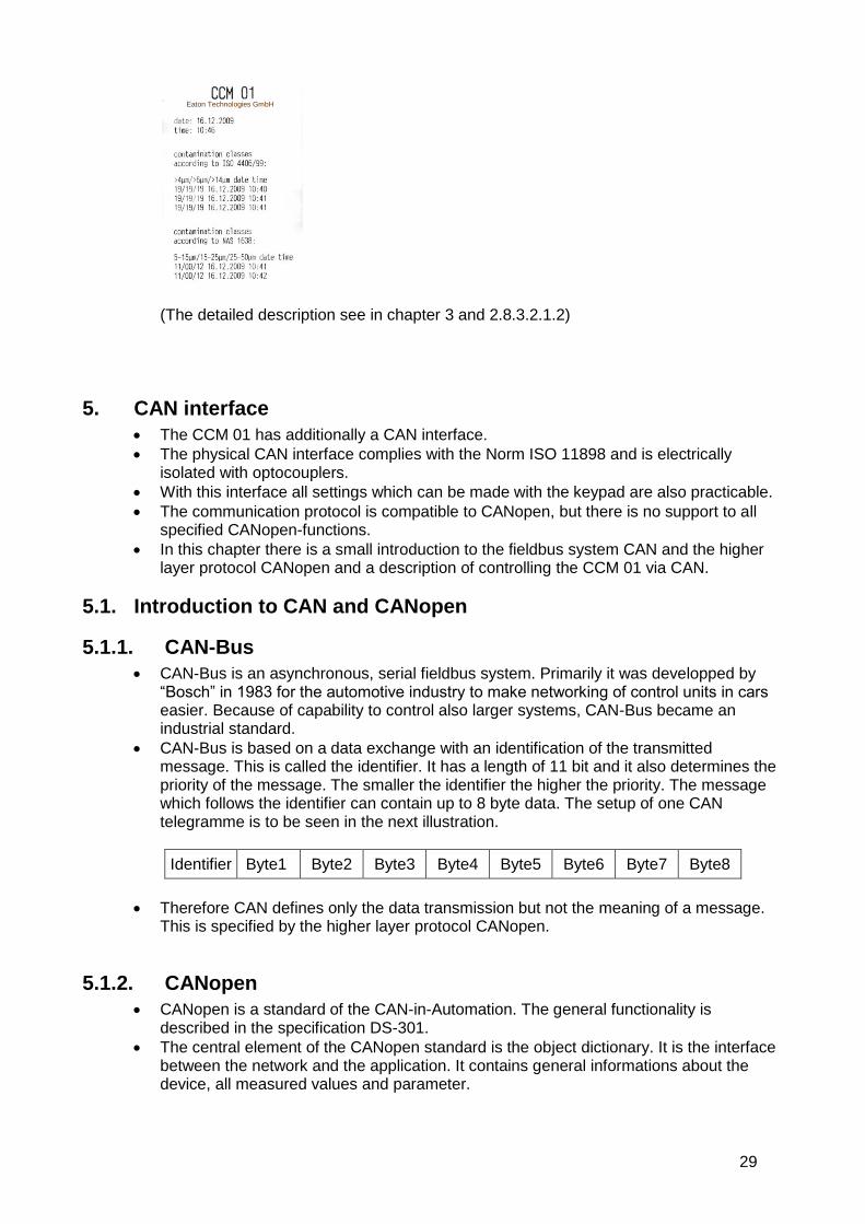
29
(The detailed description see in chapter 3 and 2.8.3.2.1.2)
5. CAN interface
The CCM 01 has additionally a CAN interface.
The physical CAN interface complies with the Norm ISO 11898 and is electrically isolated with optocouplers.
With this interface all settings which can be made with the keypad are also practicable.
The communication protocol is compatible to CANopen, but there is no support to all specified CANopen-functions.
In this chapter there is a small introduction to the fieldbus system CAN and the higher layer protocol CANopen and a description of controlling the CCM 01 via CAN.
5.1. Introduction to CAN and CANopen
5.1.1. CAN-Bus
CAN-Bus is an asynchronous, serial fieldbus system. Primarily it was developped by “Bosch” in 1983 for the automotive industry to make networking of control units in cars easier. Because of capability to control also larger systems, CAN-Bus became an industrial standard.
CAN-Bus is based on a data exchange with an identification of the transmitted message. This is called the identifier. It has a length of 11 bit and it also determines the priority of the message. The smaller the identifier the higher the priority. The message which follows the identifier can contain up to 8 byte data. The setup of one CAN telegramme is to be seen in the next illustration.
Identifier Byte1 Byte2 Byte3 Byte4 Byte5 Byte6 Byte7 Byte8
Therefore CAN defines only the data transmission but not the meaning of a message. This is specified by the higher layer protocol CANopen.
5.1.2. CANopen
CANopen is a standard of the CAN-in-Automation. The general functionality is described in the specification DS-301.
The central element of the CANopen standard is the object dictionary. It is the interface between the network and the application. It contains general informations about the device, all measured values and parameter.
Eaton Technologies GmbH

30
The objects or parameters are addressed with a 16-bit index and an 8-bit subindex. The build-up of the object dictionary and the access to it is described in the following chapters. CANopen defines different objects for communication.
These are: - Service Data Object (SDO): For parameter settings - Process Data Object (PDO): For transmitting process data - Network Management Object (NMT): For changing the state of a device - Emergency Object: For transmitting error and alarm messages - Timestamp Object: For adjusting the time
The differentiation of these communication objects results from the identifier. The identifier is separated in two parts.
The most significant 4 bit describe the function code which declares the type of the message, the remaining 7 bit describe the Node ID.
This separated identifier is called the Communication Object Identifier (COB-ID). Therefore it is possible in this broadcast system to communicate with single participants.
Functions code Node ID
Bit10 Bit9 Bit8 Bit7 Bit6 Bit5 Bit4 Bit3 Bit2 Bit1 Bit0
The meaning of the function code is arranged in the so-called Pre-defined connection set.
Object Function code (binary) Resulting COB-ID (dec)
NMT 0000 0
SYNC 0001 128
EMCY 0001 129 - 255
PDO1 (tx) 0011 385 – 511
PDO1 (rx) 0100 513 – 639
PDO2 (tx) 0101 641 – 767
PDO2 (rx) 0110 769 – 895
PDO3 (tx) 0111 897 – 1023
PDO3 (rx) 1000 1025 - 1151
PDO4 (tx) 1001 1153 – 1279
PDO4 (rx) 1010 1281 – 1407
SDO (tx) 1011 1409 – 1535
SDO (tx) 1100 1537 – 1663
NMT Error Control 1110 1793 - 1919
5.2. CANopen – functionality
The CCM01 does not have the complete CANopen – funtionality.
The following functions of CANopen are available: - Object dirctionary with all measured data and parameters
- One SDO-Server For parameter settings
- One transmit PDO For transmitting the measured data - Nodeguarding or Heartbeat - Emergency object for error or alarm messages - Timestamp for adjustment of time - NMT-State-Machine
5.3. Start-up
For starting the controlling with CAN you must proceed as follows.

31
Choose the submenu CAN with the [ ] buttons. Enter the chosen menu item by
hitting the [ ] button.
Now there is the menue for adjusting the baudrate, the node ID and for starting the controlling with CAN. These settings are basically for communication with CAN.
5.3.1. Baudrate
Use the [ ] button to choose the baudrate.
The following baudrates can be chosen: 10 kbit/s 20 kbit/s 50 kbit/s 125 kbit/s 250 kbit/s 500 kbit/s 800 kbit/s 1 Mbit/s (1000 kbit/s)
Confirm by hitting the [ ] button and automatic return to the [CAN] – menu.
Use [ ESC ] to go back to the previous menu – changes will not be adopted.
The default baudrate is 125 kbit/s.
5.3.2. Node ID
By hitting the [ ] button, the position that has to be changed can be switched.
The [ ] buttons set a new parameter.
The values of the node ID must be between 1 and 127.
Confirm by hitting the [ ] button – automatic return to the [CAN] – menu.

32
Use [ ESC ] to go back to the previous menu – changes will not be adopted.
The default node ID is 1.
5.3.3. Start
For starting the controlling with CAN use the [ ] buttons to select the item START.
Confirm by hitting the [ ] button.
Now all parameter settings can be made with the CAN-protocol which is described in the following.
When the device is switched-off during the CAN-mode, it goes in this mode again after a reset.
Use [ ESC ] to leave the CAN-mode.
After that there is the initialisation phase, followed from the Bootup – message. This message has the following buildup:
Identifier Data
700h + Node ID 00h
If this message could not be sent there is a message “TRANSMIT ERROR” on the display for 1 second.
After this message the state Pre-Operational is achieved.
In the menu bar you can see a “c”.
This is the sign that the device is now controlled with CAN. The state of the device is shown on the display.
As soon as the device is put into the state Operational, measurement is started. In this state the contamination classes are shown on the display according to the chosen report format.
5.4. Object dictionary
The object dictionary has a buildup like a table with lines and columns.
An entry of the object dictionary is addressed with an index and a subindex.

33
The object dictionary of the CCM01 is subdivided into two parts: - communication specific part - manufacturer specific part
All parameters and measured values are accessible via the standard-SDO with an index and a subindex.
In general changes after a writing access are accepted immediately and remain after a reset.
In the following chapters the two parts of the object dictionary are described with the index, subindex, data type and access and default value.
5.4.1. Communication specific part
Index (hex)
Subindex (hex)
Description Data type
Access Default value
1000 0 Device Type UNS32 ro 12Dh
1001 0 Error Register UNS8 ro 0
1002 0 Manufacturer Status Register UNS32 ro 0
100C 0 Guard Time UNS16 ro 0
100D 0 Life Time Factor UNS8 ro 0
1010 Store Parameter Field
0 Number of Entries UNS8 ro 1
1 Save all Parameters UNS32 ro 2
1012 0 COB-ID Time Stamp Object UNS32 rw 100h
1014 0 COB-ID Emergency Object UNS32 ro 80h + NID
1017 0 Producer Heartbeat Time UNS16 rw 0
1200 Server SDO Parameter
0 Number of Entries UNS8 ro 2
1 COB-ID Client Server UNS32 ro 600h + NID
2 COB-ID Server-Client UNS32 ro 580h + NID
1800 Transmit PDO1 Communication Parameter
0 Number of Entries UNS8 ro 2
1 COB-ID used by PDO UNS32 ro 180h + NID
2 Transmission Type UNS8 ro FEh
1A00 Transmit PDO1 Mapping Parameter
0 Number of Entries UNS8 ro 4
1 1. Mapped Object UNS32 ro 50000110h
2 2. Mapped Object UNS32 ro 50000210h
3 3. Mapped Object UNS32 ro 50000310h
4 4. Mapped Object UNS32 ro 50000410h
5.4.1.1. Error register (Index 1001h)
The error register shows the error status of the device.
When an error occurs or adjusted limits are exceeded bit 0 is set (general error).
The reason of this error is indicated with the manufacturer status register.
The content of this error register is transmitted in every emergency message.
5.4.1.2. Manufacturer status register (Index 1002h)
This register shows the actual state of all detectable errors.
Every bit stands for a specific error.
If a bit is set this error is active.
The buildup of this register is as follows:
34
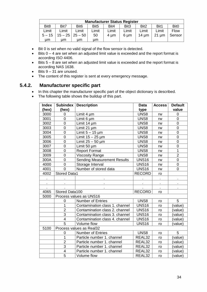
Manufacturer Status Register
Bit8 Bit7 Bit6 Bit5 Bit4 Bit3 Bit2 Bit1 Bit0
Limit 5 – 15
µm
Limit 15 – 25
µm
Limit 25 – 50
µm
Limit 50 µm
Limit 4 µm
Limit 6 µm
Limit 14 µm
Limit 21 µm
Flow Sensor
Bit 0 is set when no valid signal of the flow sensor is detected.
Bits 0 – 4 are set when an adjusted limit value is exceeded and the report format is according ISO 4406.
Bits 5 – 8 are set when an adjusted limit value is exceeded and the report format is according NAS 1638.
Bits 9 – 31 are unused.
The content of this register is sent at every emergency message.
5.4.2. Manufacturer specific part
In this chapter the manufacturer specific part of the object dictionary is described.
The following table shows the buildup of this part.
Index (hex)
Subindex (hex)
Description Data type
Access Default value
3000 0 Limit 4 µm UNS8 rw 0
3001 0 Limit 6 µm UNS8 rw 0
3002 0 Limit 14 µm UNS8 rw 0
3003 0 Limit 21 µm UNS8 rw 0
3004 0 Limit 5 – 15 µm UNS8 rw 0
3005 0 Limit 15 – 25 µm UNS8 rw 0
3006 0 Limit 25 – 50 µm UNS8 rw 0
3007 0 Limit 50 µm UNS8 rw 0
3008 0 Report Format UNS8 rw 1
3009 0 Viscosity Range UNS8 rw 2
300A 0 Sending Measurement Results UNS16 rw 0
4000 0 Storage Interval UNS16 rw 0
4001 0 Number of stored data UNS16 rw 0
4002 Stored Data1 RECORD ro
. . . . . .
. . . . . .
. . . . . .
4065 Stored Data100 RECORD ro
5000 Process values as UNS16
0 Number of Entries UNS8 ro 5
1 Contamination class 1. channel UNS16 ro (value)
2 Contamination class 2. channel UNS16 ro (value)
3 Contamination class 3. channel UNS16 ro (value)
4 Contamination class 4. channel UNS16 ro (value)
5 Volume flow UNS16 ro (value)
5100 Process values as Real32
0 Number of Entries UNS8 ro 5
1 Particle number 1. channel REAL32 ro (value)
2 Particle number 1. channel REAL32 ro (value)
3 Particle number 1. channel REAL32 ro (value)
4 Particle number 1. channel REAL32 ro (value)
5 Volume flow REAL32 ro (value)

35
5.4.2.1. Threshold settings
The indexes 3000h to 3007h of the object dictionary are for threshold settings.
The limit values according ISO 4406 can be changed at the index 3000h – 3003h.
The limit values according NAS 1638 can be changed at the index 3004h – 3007h.
The value “0” stands for deactivation of limit values monitoring.
At the threshold setting according NAS 1638 the decimal value 13 is equivalent to contamination class ”00” and the decimal value 14 is equivalent to contamination class “0”.
5.4.2.2. Report format
At the index 3008h the classification can be changed.
The value 1 means a classification according ISO 4406, the value 2 means a classification according NAS 1638.
This adjustment should not be made in the state operational.
5.4.2.3. Viscosity range
At the index 3009h the viscosity range can be changed.
The context between the value and the viscosity range is illustrated in the next table.
Value 1 2 3
Viscosity range (mm²/s) 10...33 33...250 > 250
5.4.2.4. Sending measurement results
Transmission of the PDO takes place after the number of measurements which can be changed Index 300Ah.
The time of one measurement is 20 seconds.
That means that at a value of 1 the result is sent after every measurement (every 20 seconds).
With a value of 0 the results are not transmitted.
5.4.2.5. Storage interval
The storage interval is at the index 4000h.
The unit is minutes and it can be changed between 0 (storage interval off) and 10080 (7 days).
5.4.2.6. Stored data
At the index 4001h there is the number of the stored measurement results.
100 measurements can be stored.
Deletion can be made with a writing access to the index 4001h, subindex 0h and the value 0.
The stored data are at the following indexes.
The first possible data set is at index 4002h, the last one at index 4065h.
At a query of not existing data sets the abort code “06010000h” (Unsupported acces to an object) is sent.
Following there is the buildup of one data set.
Index (hex)
Subindex (hex)
Description Data type
Access Default value
4002 0 Number of entries UNS8 ro 11
1 Day UNS8 ro
2 Month UNS8 ro
3 Year UNS8 ro
4 Hour UNS8 ro
5 Minute UNS8 ro
36
6 Report format UNS8 ro
7 Particles/ml 1. channel REAL32 ro
8 Particles/ml 2. channel REAL32 ro
9 Particles/ml 3. channel REAL32 ro
A Particles/ml 4. channel REAL32 ro
B Volume flow REAL32 ro
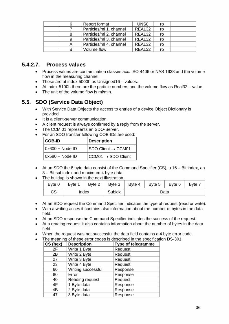
5.4.2.7. Process values
Process values are contamination classes acc. ISO 4406 or NAS 1638 and the volume flow in the measuring channel.
These are at index 5000h as Unsigned16 – values.
At index 5100h there are the particle numbers and the volume flow as Real32 – value.
The unit of the volume flow is ml/min.
5.5. SDO (Service Data Object)
With Service Data Objects the access to entries of a device Object Dictionary is provided.
It is a client-server communication.
A client request is always confirmed by a reply from the server.
The CCM 01 represents an SDO-Server.
For an SDO transfer following COB-IDs are used:
COB-ID Description
0x600 + Node ID SDO Client CCM01
0x580 + Node ID CCM01 SDO Client
At an SDO the 8 byte data consist of the Command Specifier (CS), a 16 – Bit index, an 8 – Bit subindex and maximum 4 byte data.
The buildup is shown in the next illustration.
Byte 0 Byte 1 Byte 2 Byte 3 Byte 4 Byte 5 Byte 6 Byte 7
CS Index Subidx Data
At an SDO request the Command Specifier indicates the type of request (read or write).
With a writing acces it contains also information about the number of bytes in the data field.
At an SDO response the Command Specifier indicates the success of the request.
At a reading request it also contains information about the number of bytes in the data field.
When the request was not successful the data field contains a 4 byte error code.
The meaning of these error codes is described in the specification DS-301.
CS (hex) Description Type of telegramme
2F Write 1 Byte Request
2B Write 2 Byte Request
27 Write 3 Byte Request
23 Write 4 Byte Request
60 Writing successful Response
80 Error Response
40 Reading request Request
4F 1 Byte data Response
4B 2 Byte data Response
47 3 Byte data Response

37
43 4 Byte data Response
The CCM 01 supports only the transmission of data with a maximum length of 4 Byte!
5.6. Transmit PDO
The CCM 01 has one Transmit PDO (TPDO).
This contains the measurement results in contamination classes according ISO 4406 or NAS 1638.
The identifier is static (180h + Node ID).
The transmission type is 254 und also static. That means the transmission type is defined in the manufacturer specific part of the object dictionary. It was described in section 5.4.2.4.
PDO Mapping is also static and it is described in the next illustration.
Byte 0 Byte 1 Byte 2 Byte 3 Byte 4 Byte 5 Byte 6 Byte 7
Idx 5000, Sidx 1 Idx 5000, Sidx 2 Idx 5000, Sidx 3 Idx 5000, Sidx 4
The Transmit PDO can also be requested with a Remote Frame.
5.7. Emergency Messages
With an exceeding of the limit values or with an error of the flow sensor an emergency message will be sent.
The identifier is 80h + Node ID.
The message consists of the Emergency Error Code, the Error Register and the Manufacturer Status Register.
The type of error is indicated by the Manufacturer Status Register (5.4.1.2).
Byte 0 Byte 1 Byte 2 Byte 3 Byte 4 Byte 5 Byte 6 Byte 7
Emergency Error Code
Error Reg.
Manufacturer Status Register unused
5.8. Guarding
For guarding Heartbeat- or Nodeguarding-mechanism can be used.
It can only be used one error control mechanism at the same time.
5.8.1. Nodeguarding
The CCM01 only supports Nodeguarding.
Lifeguarding is not supported.
An NMT Master cyclically sends a remote frame to an NMT Slave.
The identifier is 700h + Node ID.
The response of the NMT slave contains the state of that NMT Slave and an alternating toggle bit.
An error is indicated if the remote transmit request is not confirmed within the node life time or the reported NMT slave state does not match the expected state.
Nodeguarding is only possible when the parameter “Producer Heartbeat Time” (1017h) is 0.
5.8.2. Heartbeat
The Heartbeat mechanism defines an Error Control Service without need for remote frames.
A Heartbeat Producer transmits a Heartbeat message cyclically.

38
The identifier is 700h + Node ID and it contains the MT state of the NMT Slave.
It is activated when the parameter “Producer Heartbeat Time” (1017h) is bigger than 0.
5.9. Timestamp
The Timestamp-Object can be used for setting the time.
This protocol is a timestamp with a length of 6 Byte. It consists of the days since 1. January 1984 and the milliseconds after midnight.
The default value of the identifier is 100h. It can be changed at the index 1012h. A receipt for the timestamp is only possible in the state Pre-Operational and when the MSB of the Object 1012h is 1.
5.10. Network Management
The state machine is implemented according DS-301. The CCM 01 supports the following orders: - Start Remote Node - Stop Remote Node - Enter Pre-Operational - Reset Node - Reset Communication
5.11. EDS-file
For the CCM01 an electronic data sheet (EDS-file) is available. It contains a complete description of the object dictionary and it serves for an easy integration in a CANopen configuration tool.
5.12. Examples for CAN-communication
In this chapter there are some examples for controlling the CCM 01 via CAN. All numbers are in hexadecimal representation. Node ID 5, request limit 4 µm:
Identifier 8 Byte Data
Client 605 40 00 30 00 00 00 00 00
Response CCM 01 585 4F 00 30 00 xx 00 00 00
Node ID 5, set viscosity range to 10…33 mm²/s:
Identifier 8 Byte Data
Client 605 2F 09 30 00 01 00 00 00
Response CCM 01 585 60 09 30 00 00 00 00 00
Node ID 15, request particle number 1. channel:
Identifier 8 Byte Data
Client 60F 40 00 51 01 00 00 00 00
Response CCM 01 58F 43 00 51 01 xx xx xx xx
Node ID 15, Start Remote Node:
Identifier 2 Byte
Master 0 01 0F oder 01 00
6. Sensor calibration
The laser sensor is calibrated with ISO MTD according to ISO 11171 and is to delivered with a calibration certificate.
12 months are the validity of the calibration certificate.

39
Eaton recommends a calibration interval of 1 year. For the secondary calibration send the sensor to Eaton Technologies GmbH in Altlussheim.
The calibraton and maintenance package for the sensor contains: - Function test of the sensor and the CCM 01 - Calibration with calibration certificate - Programming of the new calibration values in the CCM 01 - 24 h function test
Upon delivery the calibration values of the attached laser sensor are programmed in the CCM 01.
When only the PFS 01 sensor was sent to calibration, the calibration values must be entered into the CCM 01.
If the laser sensor is recalibrated or exchanged, also the programmed calibration values in the CCM 01 have to be changed. The input of the new calibration values is described in chapter 2.8.3.3.3

40
7. Appendix
7.1. Technical Data
7.1.1. Laser sensor Measuring principle: Particle counting based on the light
blockade principle Calibration of particle sizes: ISO MTD in oil (ISO 11171:2000)
Limit of coincidence: 10.000 particles / ml ( 5 %)
Maximum acceptable operating pressure: 50 bar / 725 psi
Maximum oil temperature: 70 °C / 158 °F
Viscosity range: 10......400 mm2/s / 45...1854 SUS
Ambient temperature: 0...+ 70 °C / 32...158 °F
Minimum volume flow: 500 ml/ min / 0,132 gal/ min
Maximum acceptable volume flow: 50 l/min / 13,3 gal/ min
Connections: Pipes 1“ or ¾“
Connector plug: Sub D
Protection class: IP 65
Weight: 1,5 kg / 3,3 lb (m)
Operating fluids: Mineral oil based hydraulic- and lubricating fluids (see separate list for compatibility)
7.1.2. CCM 01 – Display unit Measuring method: Automatic particle counting
Particle sizes (switchable): > 4 µm(c) , > 6 µm(c), >14 µm(c), > 21 µm(c), or > 6,4 µm(c), >14 µm(c), > 21 µm(c), > 37 µm(c)
Display of contamination classes: ISO 4 - 24 NAS 00 – 12
Accuracy of measurement: ± 1 (contamination classes)
Display: 4 – rows with 16 digits each
Ambient temperature: 0 ...+ 70 °C / 32...158 °F
Controls: 4 – buttons
Protection class: IP 65
Power supply: + 24 V DC
Ripple: < 300 mVPP
Storage capacity: 100 measurements
41
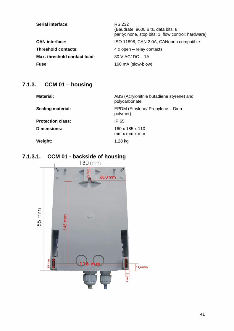
Serial interface: RS 232 (Baudrate: 9600 Bits, data bits: 8, parity: none, stop bits: 1, flow control: hardware)
CAN interface: ISO 11898, CAN 2.0A, CANopen compatible
Threshold contacts: 4 x open – relay contacts
Max. threshold contact load: 30 V AC/ DC – 1A
Fuse: 160 mA (slow-blow)
7.1.3. CCM 01 – housing
Material: ABS (Acrylonitrile butadiene styrene) and polycarbonate
Sealing material: EPDM (Ethylene/ Propylene – Dien polymer)
Protection class: IP 65
Dimensions: 160 x 185 x 110 mm x mm x mm
Weight: 1,28 kg
7.1.3.1. CCM 01 - backside of housing

42
7.2. Pin assignment
7.2.1. Laser sensor
Connection color (connection cable): X11 1: blue ﴾ → 4...20 mA flow rate sensor 2 2: green ﴾ → laser particle sensor 5 3: grey → ) - 12 V DC 13 4: yellow → ) + 12 V DC 14 5: black GND 15 (review 2.6) 6: white GND 16 7: brown → ) + 5 V DC 18
7.2.2. CCM 01 – display unit
7.2.2.1. RS 232 interface and CAN – option
CAN – option RESET RS-232
SV 2
SV 1

43
7.2.2.2. Sensor connections – X11
13 14 15 16 17 18 19 20 21 22 23 24
1 2 3 4 5 6 7 8 9 10 11 12
1: .... 2: blue - → ) 4...20 mA flow rate sensor 3: ..... 4: ..... 5: green - → ) laser particle sensor 6: ..... 7: GND 8: GND 9: REL 4 contact 1 ( 4 µm(c) / 5 – 15 µm) 10: REL 3 contact 1 ( 6 µm(c) / 15 – 25 µm) 11: REL 2 contact 1 (14 µm(c) / 25 – 50 µm) 12: REL 1 contact 1 (21 µm(c) / > 50 µm) 13: grey - ﴾ → - 12 V DC 14: yellow - ﴾ → + 12 V DC 15: black – GND (review 2.6) 16: white - GND 17: GND 18: ﴾ → + 5 V DC 19: ..... 20: ..... 21: REL 4 contact 2 ( 4 µm(c) / 5 – 15 µm) 22: REL 3 contact 2 ( 6 µm(c) / 15 – 25 µm) 23: REL 2 contact 2 (14 µm(c) / 25 – 50 µm) 24: REL 1 contact 2 (21 µm(c) / > 50 µm)
7.2.2.3. Power supply – 24 V DC
24V

44
7.3. Pressure difference characateristics
0
0,5
1
1,5
2
2,5
0 10 20 30 40 50 60 70
ba
r
l/min
Pressure difference characteristics of the PFS 01 mit HLP 46
20°C
25°C
30°C
35°C
40°C
45°C

45
7.4. Cleanliness classes according to ISO 4406:99 According to ISO 4406 (year 1999) the number of particles sized > 4 µm(c), > 6 µm(c) and > 14 µm(c) is being used to determine the cleanliness class. The determination of the cleanliness class doesn’t depend on the particle size. Example of presenting: 20 / 16 / 12 Analysis volume: 1 ml
Cleanliness class Number of particles .......... Up to and including
26 320000 640000
25 160000 320000
24 80000 160000
23 40000 80000
22 20000 40000
21 10000 20000
20 5000 10000
19 2500 5000
18 1300 2500
17 640 1300
16 320 640
15 160 320
14 80 160
13 40 80
12 20 40
11 10 20
10 5 10
9 2,5 5
8 1,3 2,5
7 0,6 1,3
6 0,3 0,6
Partikel > 14 µm(c)
Partikel > 6 µm(c)
Partikel > 4 µm(c)

46
7.5. Cleanliness classes according to NAS 1638
Analysis volume: 100 ml
Particle number x 10³
Class 5 - 15 µm 15 - 25 µm 25 - 50 µm 50 - 100 µm > 100 µm
00 0,125 0,022 0,004 0,001 0
0 0,250 0,044 0,008 0,002 0
1 0,5 0,089 0,016 0,003 0,001
2 1 0,178 0,032 0,006 0,001
3 2 0,356 0,063 0,011 0,002
4 4 0,712 0,126 0,022 0,004
5 8 1,425 0,253 0,045 0,008
6 16 2,85 0,506 0,090 0,016
7 32 5,7 1,012 0,18 0,032
8 64 11,40 2,025 0,36 0,064
9 128 22,8 4,05 0,72 0,128
10 256 45,6 8,1 1,44 0,256
11 512 91,2 16,2 2,88 0,512
12 1024 182,4 32,4 5,76 1,024

47
7.6. Application areas - Compatibility
- Hydraulic oils H, HL, HLP, and HV
- Gear oils C, CL, CLP
- Motor oils, gas oils
- MIL-H-5606 E
- Vegetable oils (HTG, Triglyceride)
- Synthetic ester (HEES)
7.7. Trouble shooting No settings of the CCM 01 are done by the operator. Malfunctions, which could be eliminated by the operator, are limited to cleaning the sensor and checking cables for brakes. Any other case requires sending in the sensor or the display unit CCM 01 to Eaton Technologies GmbH in order to recover the functions. A brief description of the problem would expedite the trouble shooting and the repair process. To check your warranty and to answer questions by phone we need the serial number and the date of purchase of the instrument.
7.8. Shipment
Article no.: (1) Monitor CCM 01 327153 (2) Sensor PFS 01 327213 (3) Sensor cabel, L = 5 m 327320 (4) RS232 – connecting plug 335649 (5) RS232 – connecting cable 326762 (6) Data manager CD 327284 (7) Instruction manual
Optional: 1. Voltage supply 24 V, 625 mA 329932 2. Waterproof data cable (fixed connected) 329931 3. EBT 01 334002 4. Printer 338250 5. USB to RS232 adaptor plug 336300

North America — HQ 70 Wood Ave., South, 2nd Floor Iselin, NJ 08830 Toll Free: (800) 656-3344 (North America Only) Voice: (732) 767-4200 China No. 3, Lane 280, Linhong Road Changning District, 200335 Shanghai, P.R. China Voice: +86-21-5200-0099 Singapore 4 Loyang Lane #04-01/02 Singapore 508914 Voice: +65-6825-1668
Europe/Africa/Middle East Friedensstraße 41 D-68804 Altlussheim, Germany Voice: +49-6205-2094-0 Auf der Heide 2 53947 Nettersheim, Germany Voice: +49-2486-809-0 An den Nahewiesen 24 55450 Langenlonsheim, Germany Voice: +49 6704 204-0 Brazil Av. Julia Gaioli, 474 – Bonsucesso 07251-500 – Guarulhos, Brazil Voice: +55 (11) 2465-8822
For more information, please e-mail us at [email protected] Visit us online eaton.com/filtration for a complete list of Eaton´s filtration products. ©2012 Eaton Corporation. All Rights Reserved. All trademarks and registered trademarks are the property of their respective owners. Litho USA.
All information and recommendations appearing in this brochure concerning the use of products described herein are based on tests believed to be reliable. However, it is the user’s responsibility to determine the suitability for his own use of such products. Since the actual use by others is beyond our control, no guarantee, expressed or implied, is made by Eaton as to the effects of such use or the results to be obtained. Eaton assumes no liability arising out of the use by others of such products. Nor is the information herein to be construed as absolutely complete, since additional information may be necessary or desirable when particular or exceptional conditions or circumstances exist or because of applicable laws or government regulations.