Embed Size (px)
Citation preview
Vossloh-Schwabe Deutschland GmbH · Hohe Steinert 8 · 58509 Lüdenscheid · Germany · Phone +49 23 51/10 10 · Fax +49 23 51/10 12 17 · www.vossloh-schwabe.com
CC COMPACT SIMPLE FIX
LED Drivers
COMFORTLINE SIMPLE FIX C-R3186719, 186720, 186721, 186722, 186723, 186724, 186725, 186726, 186727, 186728
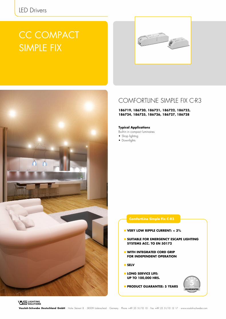
Typical ApplicationsBuilt-in in compact luminaires• Shop lighting• Downlights
ComfortLine Simple Fix C-R3
VERY LOW RIPPLE CURRENT: < 3%
SUITABLE FOR EMERGENCY ESCAPE LIGHTING SYSTEMS ACC. TO EN 50172
WITH INTEGRATED CORD GRIP FOR INDEPENDENT OPERATION
SELV
LONG SERVICE LIFE: UP TO 100,000 HRS.
PRODUCT GUARANTEE: 5 YEARS
2Vossloh-Schwabe Deutschland GmbH · Hohe Steinert 8 · 58509 Lüdenscheid · Germany · Phone +49 23 51/10 10 · Fax +49 23 51/10 12 17 · www.vossloh-schwabe.com
The values contained in this data sheet can change due to technical innovations. Any such changes will be made without separate notification.
CC
-Com
fortL
ine-
Sim
ple-
Fix-C
-R3_
1867
19-1
8672
0-18
6721
-186
722-
1867
23-1
8672
4-18
6725
-186
726-
1867
27-1
8672
8_EN
– 2
/8
– 06
/20
19LED Drivers – ComfortLine Simple Fix C-R3
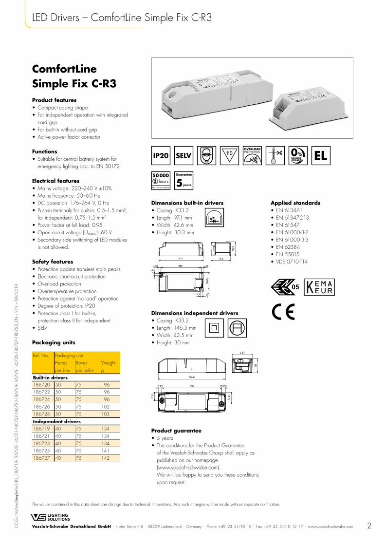
ComfortLine Simple Fix C-R3Product features• Compact casing shape• For independent operation with integrated
cord grip• For built-in without cord grip• Active power factor corrector
Functions• Suitable for central battery system for
emergency lighting acc. to EN 50172
Electrical features• Mains voltage: 220–240 V ±10%• Mains frequency: 50–60 Hz• DC operation: 176–264 V, 0 Hz• Push-in terminals for built-in: 0.5–1.5 mm²,
for independent: 0.75–1.5 mm²• Power factor at full load: 0.95• Open circuit voltage (Umax.): 60 V• Secondary side switching of LED modules
is not allowed.
Safety features• Protection against transient main peaks• Electronic short-circuit protection• Overload protection• Overtemperature protection• Protection against "no load" operation• Degree of protection: IP20• Protection class I for built-in,
protection class II for independent• SELV
Packaging units
Ref. No. Packaging unit
Pieces Boxes Weight
per box per pallet g
Built-in drivers186720 50 75 96
186722 50 75 96
186724 50 75 96
186726 50 75 102
186728 50 75 103
Independent drivers186719 40 75 134
186721 40 75 134
186723 40 75 134
186725 40 75 141
186727 40 75 142
Dimensions built-in drivers• Casing: K33.2 • Length: 97.1 mm• Width: 42.6 mm• Height: 30.3 mm
Dimensions independent drivers• Casing: K33.2 • Length: 146.5 mm• Width: 43.5 mm• Height: 30 mm
Product guarantee• 5 years• The conditions for the Product Guarantee
of the Vossloh-Schwabe Group shall apply as published on our homepage (www.vossloh-schwabe.com). We will be happy to send you these conditions upon request.
Applied standards• EN 61347-1• EN 61347-2-13• EN 61547• EN 61000-3-2• EN 61000-3-3• EN 62384• EN 55015• VDE 0710-T14
3Vossloh-Schwabe Deutschland GmbH · Hohe Steinert 8 · 58509 Lüdenscheid · Germany · Phone +49 23 51/10 10 · Fax +49 23 51/10 12 17 · www.vossloh-schwabe.com
The values contained in this data sheet can change due to technical innovations. Any such changes will be made without separate notification.
CC
-Com
fortL
ine-
Sim
ple-
Fix-C
-R3_
1867
19-1
8672
0-18
6721
-186
722-
1867
23-1
8672
4-18
6725
-186
726-
1867
27-1
8672
8_EN
– 3
/8
– 06
/20
19LED Drivers – ComfortLine Simple Fix C-R3
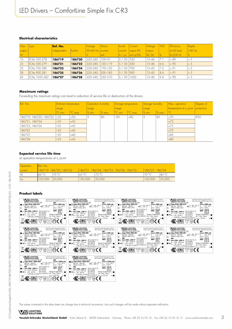
Electrical characteristics
Max. Type Ref. No. Voltage Mains Inrush Current Voltage THD Efficiency Ripple
output independent built-in 50–60 Hz current current output DC output at full load 100 Hz
W V mA A / µs mA (±5%) DC (V) % % (230 V) %
16 ECXe 350.278 186719 186720 220–240 100–91 5 / 50 350 15–46 7.1 > 89 < 3
23 ECXe 500.279 186721 186722 220–240 130–119 5 / 50 500 15–46 6.6 > 90 < 3
32 ECXe 700.280 186723 186724 220–240 170–150 5 / 50 700 15–45 7.2 > 91 < 3
38 ECXe 900.281 186725 186726 220–240 200–183 5 / 50 900 15–42 8.6 > 91 < 3
42 ECXe 1050.282 186727 186728 220–240 230–210 5 / 50 1050 15–40 9.4 > 90 < 3
Maximum ratingsExceeding the maximum ratings can lead to reduction of service life or destruction of the drivers.
Ref. No. Ambient temperature Operation humidity Storage temperature Storage humidity Max. operation Degree of
range range range range temperature at tc point protection
°C min. °C max. % min. % max. °C min. °C max. % min. % max. °C
186719, 186720, 186722 –25 +50 5 80 –30 +80 5 85 +70 IP20
186721, 186724 –25 +50 +75
186723, 186726 –25 +45 +75
186725 –25 +40 +75
186727 –25 +40 +80
186728 –25 +45 +80
Expected service life timeat operation temperatures at tc point
Operation Ref. No.
current 186719, 186720, 186722 186721, 186724, 186723, 186726, 186725 186727, 186728
All 60 °C 70 °C 65 °C 75 °C 70 °C 80 °C
hrs. 100,000 50,000 100,000 50,000 100,000 50,000
Product labels
4Vossloh-Schwabe Deutschland GmbH · Hohe Steinert 8 · 58509 Lüdenscheid · Germany · Phone +49 23 51/10 10 · Fax +49 23 51/10 12 17 · www.vossloh-schwabe.com
The values contained in this data sheet can change due to technical innovations. Any such changes will be made without separate notification.
CC
-Com
fortL
ine-
Sim
ple-
Fix-C
-R3_
1867
19-1
8672
0-18
6721
-186
722-
1867
23-1
8672
4-18
6725
-186
726-
1867
27-1
8672
8_EN
– 4
/8
– 06
/20
19LED Drivers – ComfortLine Simple Fix C-R3
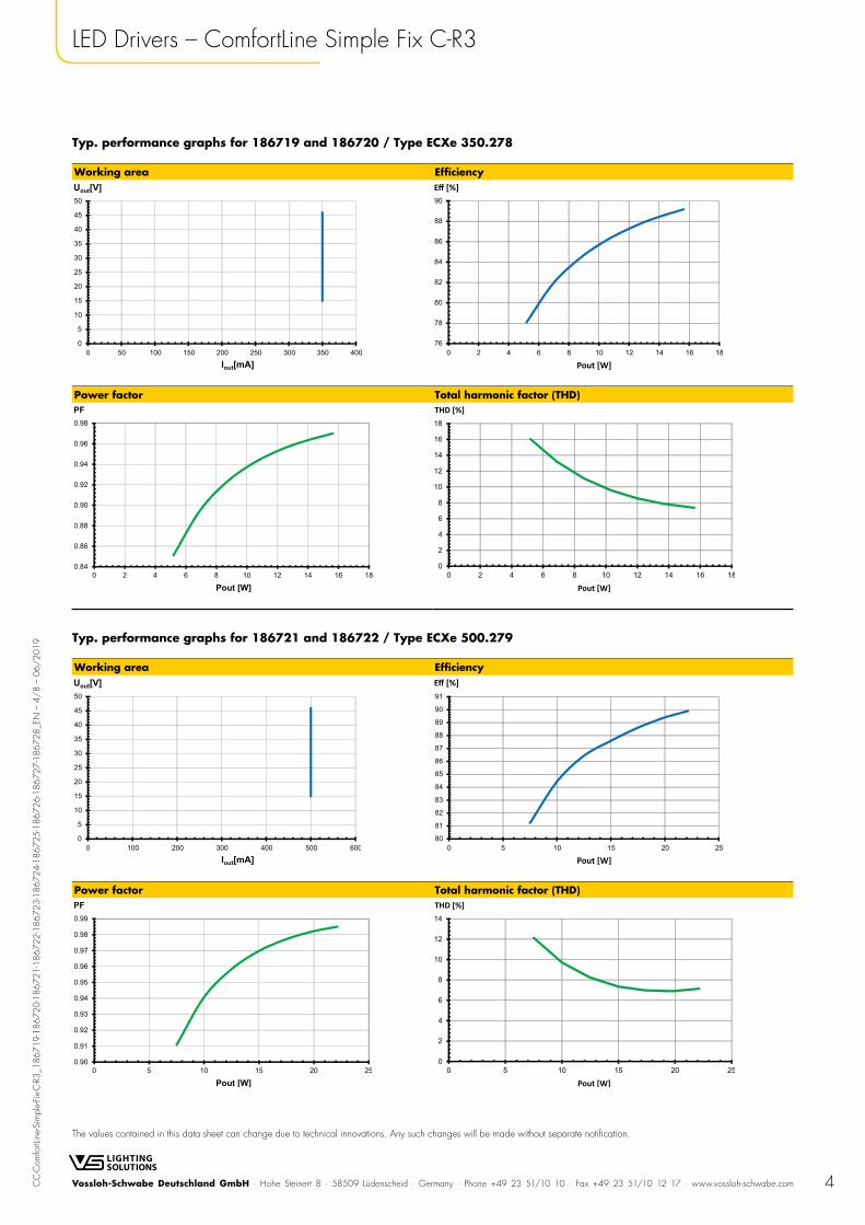
Typ. performance graphs for 186719 and 186720 / Type ECXe 350.278
Working area Efficiency
Power factor Total harmonic factor (THD)
Typ. performance graphs for 186721 and 186722 / Type ECXe 500.279
Working area Efficiency
Power factor Total harmonic factor (THD)
5Vossloh-Schwabe Deutschland GmbH · Hohe Steinert 8 · 58509 Lüdenscheid · Germany · Phone +49 23 51/10 10 · Fax +49 23 51/10 12 17 · www.vossloh-schwabe.com
The values contained in this data sheet can change due to technical innovations. Any such changes will be made without separate notification.
CC
-Com
fortL
ine-
Sim
ple-
Fix-C
-R3_
1867
19-1
8672
0-18
6721
-186
722-
1867
23-1
8672
4-18
6725
-186
726-
1867
27-1
8672
8_EN
– 5
/8
– 06
/20
19LED Drivers – ComfortLine Simple Fix C-R3
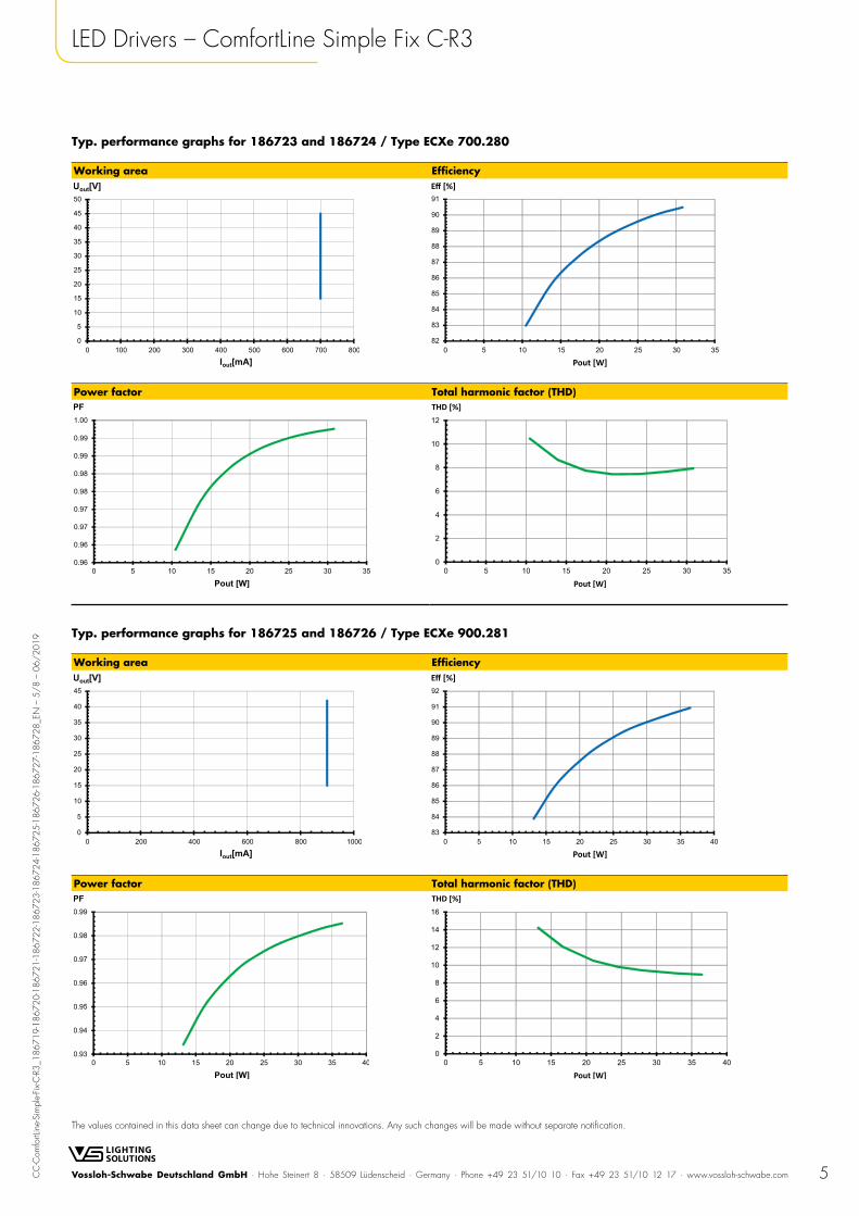
Typ. performance graphs for 186723 and 186724 / Type ECXe 700.280
Working area Efficiency
Power factor Total harmonic factor (THD)
Typ. performance graphs for 186725 and 186726 / Type ECXe 900.281
Working area Efficiency
Power factor Total harmonic factor (THD)
6Vossloh-Schwabe Deutschland GmbH · Hohe Steinert 8 · 58509 Lüdenscheid · Germany · Phone +49 23 51/10 10 · Fax +49 23 51/10 12 17 · www.vossloh-schwabe.com
The values contained in this data sheet can change due to technical innovations. Any such changes will be made without separate notification.
CC
-Com
fortL
ine-
Sim
ple-
Fix-C
-R3_
1867
19-1
8672
0-18
6721
-186
722-
1867
23-1
8672
4-18
6725
-186
726-
1867
27-1
8672
8_EN
– 6
/8
– 06
/20
19LED Drivers – ComfortLine Simple Fix C-R3
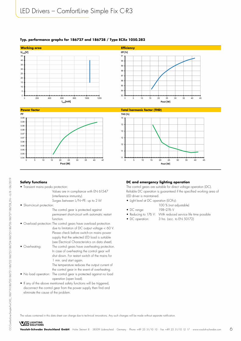
Typ. performance graphs for 186727 and 186728 / Type ECXe 1050.282
Working area Efficiency
Power factor Total harmonic factor (THD)
Safety functions• Transient mains peaks protection:
Values are in compliance with EN 61547 (interference immunity). Surges between L/N–PE: up to 2 kV
• Short-circuit protection: The control gear is protected against permanent short-circuit with automatic restart function.
• Overload protection: The control gears have overload protection due to limitation of DC output voltage < 60 V. Please check before switch-on mains power supply that the selected LED load is suitable (see Electrical Characteristics on data sheet).
• Overheating: The control gears have overheating protection. In case of overheating the control gear will shut down. For restart switch of the mains for 1 min. and start again. The temperature reduces the output current of the control gear in the event of overheating.
• No load operation: The control gear is protected against no load operation (open load).
• If any of the above mentioned safety functions will be triggered, disconnect the control gear from the power supply then find and eliminate the cause of the problem.
DC and emergency lighting operation The control gears are suitable for direct voltage operation (DC). Reliable DC operation is guaranteed if the specified working area of LED driver is maintained.• Light level at DC operation (EOFX):
100 % (not adjustable)• DC range: 198–276 V• Reducing to 176 V: With reduced service life time possible• DC operation: 3 hrs. (acc. to EN 50172)
7Vossloh-Schwabe Deutschland GmbH · Hohe Steinert 8 · 58509 Lüdenscheid · Germany · Phone +49 23 51/10 10 · Fax +49 23 51/10 12 17 · www.vossloh-schwabe.com
The values contained in this data sheet can change due to technical innovations. Any such changes will be made without separate notification.
CC
-Com
fortL
ine-
Sim
ple-
Fix-C
-R3_
1867
19-1
8672
0-18
6721
-186
722-
1867
23-1
8672
4-18
6725
-186
726-
1867
27-1
8672
8_EN
– 7
/8
– 06
/20
19LED Drivers – ComfortLine Simple Fix C-R3
Assembly and Safety InformationInstallation must be carried out under observation of the relevantregulations and standards. Installation must be carried out in avoltage-free state (i.e. disconnection from the mains). The followingadvices must be observed; non-observance can result in the destruction of the LED drivers, fire and/or other hazards.
Mandatory regulations• DIN VDE 0100• EN 60598-1
Mechanical mounting• Mounting position: Built-in: Any position inside a luminaire
is allowed Independent application: Drivers with integrated cord grip are allowed to use for independent applications.
• Mounting location: LED drivers are designed for integration into luminaires or comparable devices. Independent LED drivers do not need to be integrated into a casing. Installation in outdoor luminaires: degree of protection for luminaire with water protection rate ≥ 4 (e.g. IP54 required).
• Degree of protection: IP20
• Clearance: Min. 0.10 m from walls, ceilings and insulation
• Surface: Solid and plane surface for optimum heat dissipation required.
• Heat transfer: If the driver is destined for installation in a luminaire. sufficient heat transfer must be ensured between the driver and the luminaire casing. LED drivers should be mounted with the greatest possible clearance to heat sources. During operation. the temperature measure at the driver's tc point must not exceed the specified maximum value.
• Fastening: Using M4 screws in the designated holes• Tightening torque: 0.2 Nm
Electrical installation• Connection
terminals: Push-in terminals for rigid or flexible conductors with a section of 0.5–1.5 mm² for built-in; 0.75–1.5 mm² for independent
• Stripped length: 9–10 mm• Wiring: The mains conductor within the luminaire must
be kept short (to reduce the induction of interference). Mains and lamp conductors must be kept separate and if possible should not be laid in parallel to one another. Max. secondary side lead length for independent drivers: 1 m
• Polarity: Please ensure the correct polarity of the leads prior to commissioning. Reversed polarity can destroy the modules.
• Parallel connection: At secondary side is not allowed.• Through-wiring: Is not allowed• Secondary load: The sum of forward voltages of LED loads is
within the tolerances which are mentioned in the Electrical Characteristics on the data sheet.
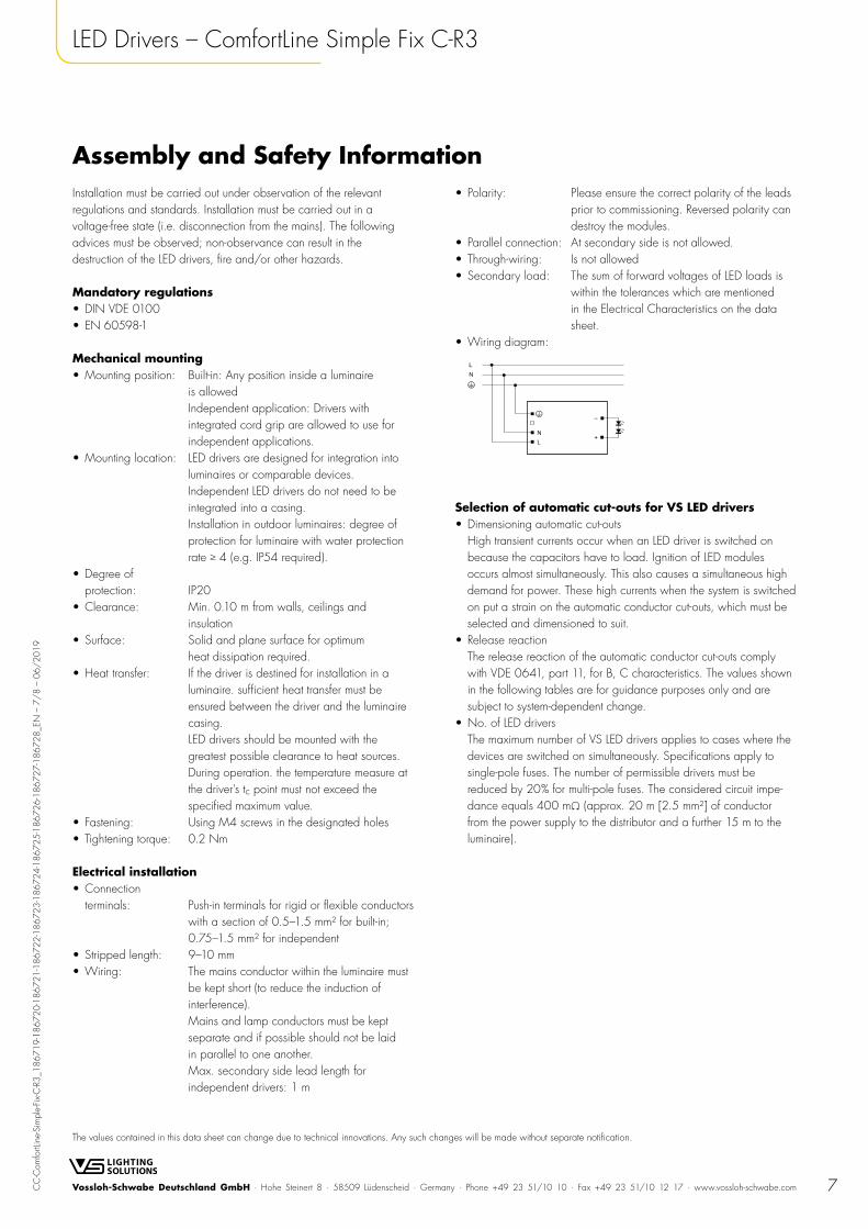
• Wiring diagram:
Selection of automatic cut-outs for VS LED drivers• Dimensioning automatic cut-outs
High transient currents occur when an LED driver is switched on because the capacitors have to load. Ignition of LED modules occurs almost simultaneously. This also causes a simultaneous high demand for power. These high currents when the system is switched on put a strain on the automatic conductor cut-outs, which must be selected and dimensioned to suit.
• Release reaction The release reaction of the automatic conductor cut-outs comply with VDE 0641, part 11, for B, C characteristics. The values shown in the following tables are for guidance purposes only and are subject to system-dependent change.
• No. of LED drivers The maximum number of VS LED drivers applies to cases where the devices are switched on simultaneously. Specifications apply to single-pole fuses. The number of permissible drivers must be reduced by 20% for multi-pole fuses. The considered circuit impe-dance equals 400 mΩ (approx. 20 m [2.5 mm²] of conductor from the power supply to the distributor and a further 15 m to the luminaire).
8Vossloh-Schwabe Deutschland GmbH · Hohe Steinert 8 · 58509 Lüdenscheid · Germany · Phone +49 23 51/10 10 · Fax +49 23 51/10 12 17 · www.vossloh-schwabe.com
The values contained in this data sheet can change due to technical innovations. Any such changes will be made without separate notification.
CC
-Com
fortL
ine-
Sim
ple-
Fix-C
-R3_
1867
19-1
8672
0-18
6721
-186
722-
1867
23-1
8672
4-18
6725
-186
726-
1867
27-1
8672
8_EN
– 8
/8
– 06
/20
19LED Drivers – ComfortLine Simple Fix C-R3
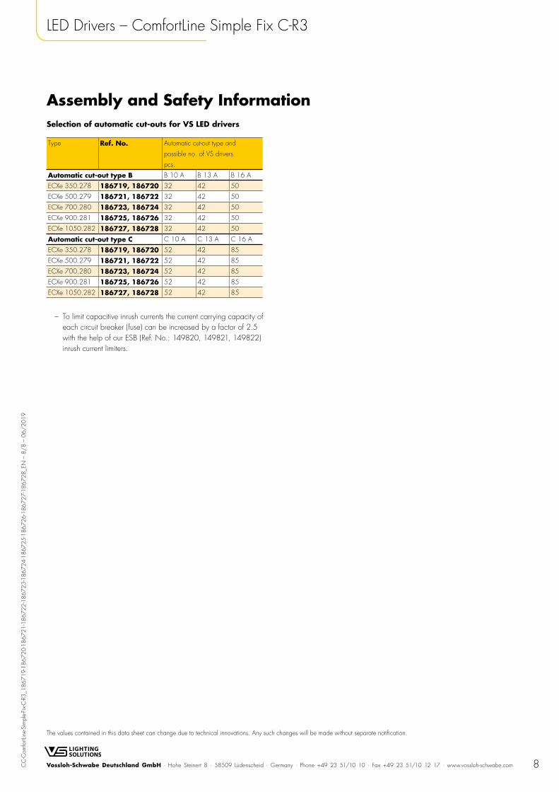
Assembly and Safety InformationSelection of automatic cut-outs for VS LED drivers
Type Ref. No. Automatic cut-out type and
possible no. of VS drivers
pcs.
Automatic cut-out type B B 10 A B 13 A B 16 A
ECXe 350.278 186719, 186720 32 42 50
ECXe 500.279 186721, 186722 32 42 50
ECXe 700.280 186723, 186724 32 42 50
ECXe 900.281 186725, 186726 32 42 50
ECXe 1050.282 186727, 186728 32 42 50
Automatic cut-out type C C 10 A C 13 A C 16 A
ECXe 350.278 186719, 186720 52 42 85
ECXe 500.279 186721, 186722 52 42 85
ECXe 700.280 186723, 186724 52 42 85
ECXe 900.281 186725, 186726 52 42 85
ECXe 1050.282 186727, 186728 52 42 85
– To limit capacitive inrush currents the current carrying capacity of each circuit breaker (fuse) can be increased by a factor of 2.5 with the help of our ESB (Ref. No.: 149820, 149821, 149822) inrush current limiters.