Embed Size (px)
Citation preview
CBSArcSafe®
RRS-1 LT
Te
ch
nic
al M
an
ua
l
P.O. Box 550 Argyle, TX 76226
(940) 382-4411 www.cbsarcsafe.com
(Remote Racking System)
Published by CBS ArcSafe®, a division of
GroupCBS, Inc. P.O. Box 1557
Gainesville, Texas 76241, USA
CBS ArcSafe®
P.O. Box 550 Argyle, Texas 76226
Copyright CBS ArcSafe® 2010
Printed in the United States of America Reproduction, adaptation, or translation without prior written permission is prohibited except as is allowed by law.
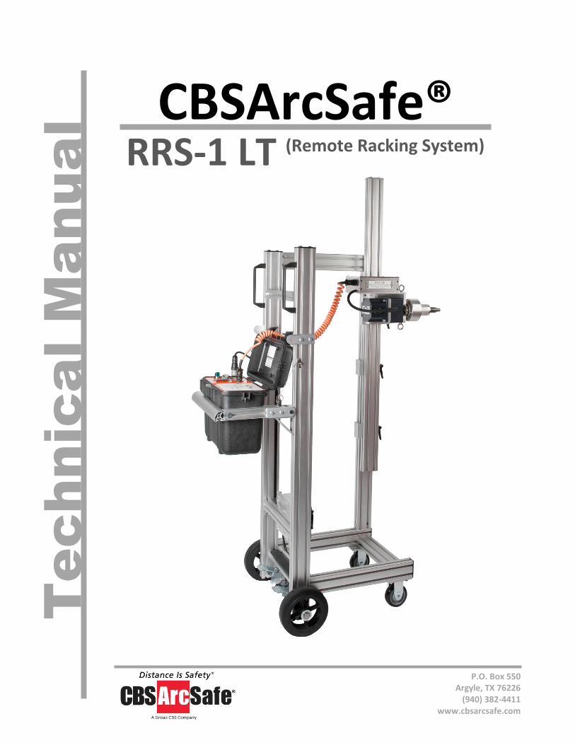
More products by CBS ArcSafe®
RRS-1 – Remote Racking System for rotary type breakers The RRS-1 is a universal remote racking system capable of removing or inserting low
and medium voltage draw out rotary circuit breakers while the operator remains outside the arc flash boundary. This device is portable, weighing less than 200 pounds, and user friendly requiring no modifications to the switchgear or circuit breakers. Each system will be custom designed to fit your switchgear needs.
RRS-2 – Remote Racking System for extraction type breakers
The RRS-2 is a universal remote racking system capable of removing or inserting low and medium voltage non-rotary circuit breakers while the operator remains outside the arc flash boundary. This device is portable, weighing less than 200 pounds, and user friendly requiring no modifications to the switchgear or circuit breaker. Each system will be custom designed to fit your switchgear needs.
RRS-3 – Single Application Remote Racking System
The RRS-3 system is an inexpensive single application remote racking system which allows the operator to install and remove a breaker while standing 25 to 75 feet away with a hand control unit. CBS ArcSafe also offers a radio remote option which allows for operation up to 150 feet away without the need for an extension cable. The radio remote option in some cases allows for closed door racking to occur once the RRS-3 has been attached to the breaker.
RSO – Remote Switch Operator A remote switch operator is the power and control console for service personnel to
remotely charge, close, and trip circuit breakers from a safe distance using a CBS ArcSafe® RSA. Each CBS ArcSafe® remote switch operator can also be operated with an optional wired/wireless pendant station.
RSA – Remote Switch Actuator A remote switch actuator allows service personnel to move, push, pull, charge, close,
and/or trip circuit breakers and other electrical equipment from a safe distance in conjunction with a CBS ArcSafe® RSO. The remote switching actuator attaches to the front of your circuit breaker and is mechanically assisted by magnets without the need for any modification to your switchgear. After setup and installation the RSO controls the RSA’s operation.
RRS-1-LT Technical Manual iii
© 2009 CBS ArcSafe™
Table of Contents 1.0 Description .................................................................................................................3
1.1 Structural Assembly ........................................................................................................ 4
Motor-Drive Unit (Fig. F.1.1) ........................................................................................................... 5
Drive Unit Height/Extended Height Adjustment (Fig. F.1.5) .......................................................... 5
1.2 Control Assembly ............................................................................................................ 6
3.0 Preparation and Setup ................................................................................................7
3.1 Set up Training ................................................................................................................ 7
3.2 Unpacking the RRS-1-LT .................................................................................................. 8
3.3 Charging the RRS-1-LT ..................................................................................................... 9
3.4 Setting the Precision Torque Limiter ............................................................................ 10
3.5 Setting up the RRS-1-LT for Operation ......................................................................... 12
3.6 Current Control Module (CCM) Configuration ............................................................. 13
3.6.1 Manual Current Control Configuration ................................................................................ 13
3.6.2 Automatic Current Control Configuration ........................................................................... 14
3.6.2 Automatic Current Control Time Stop Configuration .......................................................... 16
4.0 Operation ................................................................................................................. 17
4.1 Circuit Breaker Installation/Removal ............................................................................ 17
4.1.1 Requirements for Installation/Removal .............................................................................. 17
4.1.2 Steps for Installation/Removal ............................................................................................ 17
5.0 Maintenance ............................................................................................................. 19
5.1 Introduction .................................................................................................................. 19
5.2 Prior to Use ................................................................................................................... 19
5.3 After Use ....................................................................................................................... 19
5.4 Yearly Maintenance ...................................................................................................... 19
Appendix A: Specifications .............................................................................................. 20
RRS-1-LT Technical Manual 2
About the User’s Guide
This user’s guide describes the functions and features of the CBS ArcSafe® RRS-1-LT. This technical document is intended to act as a simplified reference for users of the equipment, allowing for safe, quick, and efficient use of the RRS-1-LT features.
Before You Begin:
DANGER!
*This is a red hazard alert warning box; red hazard alert boxes contain information pointing out potential hazards to personnel and equipment.
ATTENTION
This is a green information box; green information boxes are used to place emphasis on valuable information the user will want to pay particular attention to.
DANGER!
*Ensure that personnel using this equipment are adequately trained in the operation of the switchgear they are planning to work with; that they are correctly stationed outside the arc flash boundary; and that they comply with all applicable Federal, State, Local, and In-house safety regulations and procedures. Attention should be given to distance, angle, and personal protective equipment (PPE).
DANGER!
*Ensure that switchgear is properly maintained and in good working order before using the RRS-1-LT on your switchgear. Contact your local group CBS service provider at www.gcbs.com to assist in proper care and maintenance for your switchgear.
P.O. Box 550
Argyle, TX 76226 Tel: 940-382-4411 Fax: 940-382-9435
Website: www.CBSArcSafe.com
Email: [email protected]
RRS-1-LT Technical Manual 3
1.0 Description The CBS ArcSafe® RRS-1-LT is a compact, light-weight version of the RRS-1 remote racking system. The unit is designed for industrial environments where reduced physical restraints exist. The operation of the RRS-1-LT is identical to the standard remote racking system; however the design changes implemented to minimize the size and weight have also decreased the ratings of the unit. Compared to the standard RRS-1 remote racking system the following changes have been made:
1. The steel frame has been replaced with lighter-weight, extruded aluminum.
2. The single system has been divided into three modular units to reduce the overall size and weight.
3. The main drive motor has been replaced with a light-weight gear-motor.
4. The slide table has been changed to a lighter-weight, aluminum quick-release system.
5. The wheels have been replaced with a lighter weight version. The majority of the RRS-1-LT components and operations are identical to the standard RRS-1 remote racking system; however, the configuration and rating of the components have been altered to meet the design requirements, the following describes the applicable changes.
RRS-1-LT Technical Manual 4
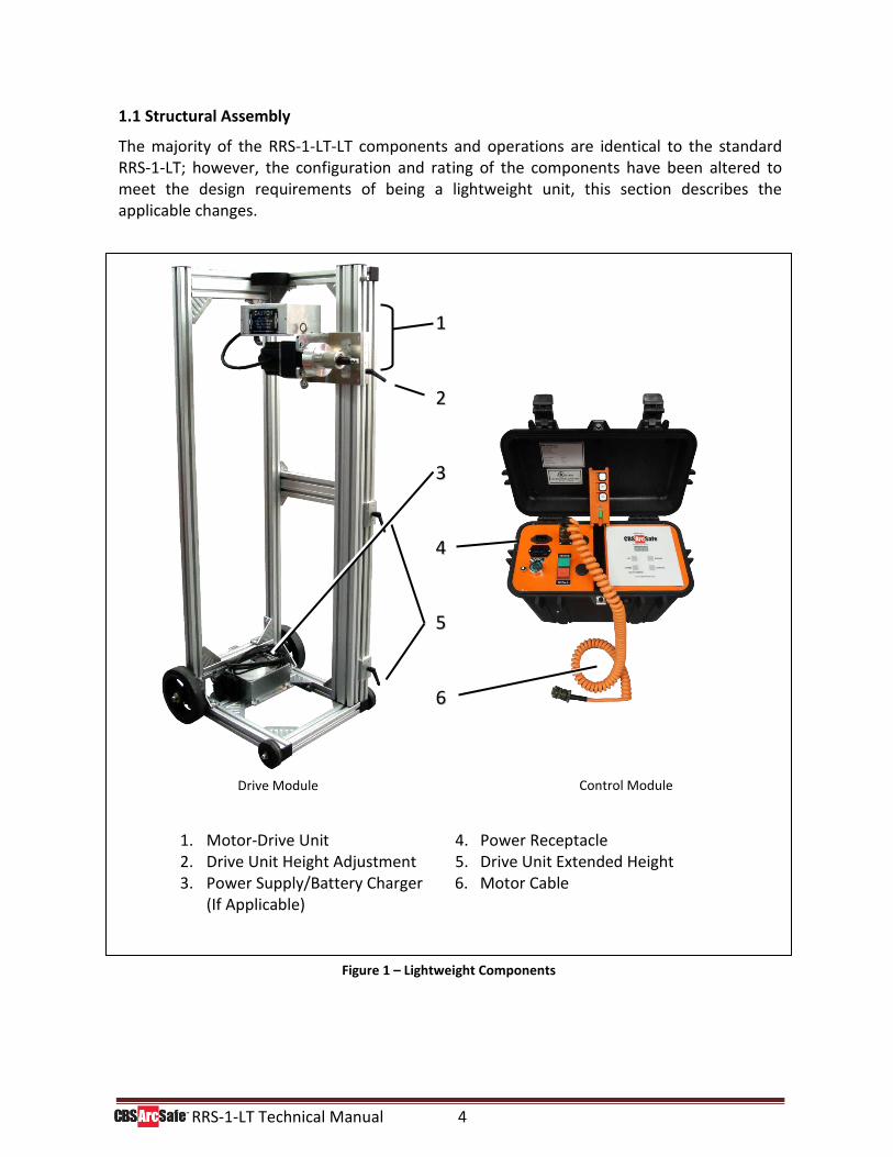
1.1 Structural Assembly
The majority of the RRS-1-LT-LT components and operations are identical to the standard RRS-1-LT; however, the configuration and rating of the components have been altered to meet the design requirements of being a lightweight unit, this section describes the applicable changes.
1. Motor-Drive Unit 4. Power Receptacle 2. Drive Unit Height Adjustment 5. Drive Unit Extended Height 3. Power Supply/Battery Charger 6. Motor Cable
(If Applicable)
Drive Module Control Module
Figure 1 – Lightweight Components
11
22
33
44
55
66
RRS-1-LT Technical Manual 5
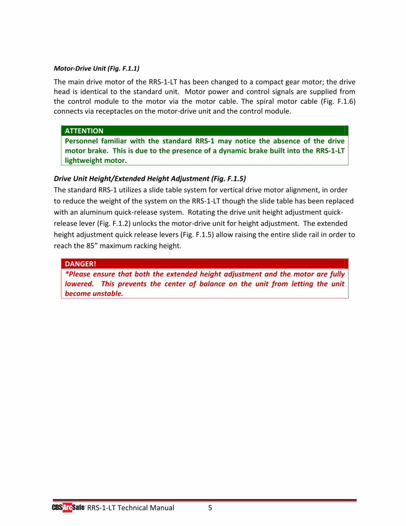
Motor-Drive Unit (Fig. F.1.1)
The main drive motor of the RRS-1-LT has been changed to a compact gear motor; the drive head is identical to the standard unit. Motor power and control signals are supplied from the control module to the motor via the motor cable. The spiral motor cable (Fig. F.1.6) connects via receptacles on the motor-drive unit and the control module.
ATTENTION
Personnel familiar with the standard RRS-1 may notice the absence of the drive motor brake. This is due to the presence of a dynamic brake built into the RRS-1-LT lightweight motor.
Drive Unit Height/Extended Height Adjustment (Fig. F.1.5)
The standard RRS-1 utilizes a slide table system for vertical drive motor alignment, in order
to reduce the weight of the system on the RRS-1-LT though the slide table has been replaced
with an aluminum quick-release system. Rotating the drive unit height adjustment quick-
release lever (Fig. F.1.2) unlocks the motor-drive unit for height adjustment. The extended
height adjustment quick release levers (Fig. F.1.5) allow raising the entire slide rail in order to
reach the 85” maximum racking height.
DANGER!
*Please ensure that both the extended height adjustment and the motor are fully lowered. This prevents the center of balance on the unit from letting the unit become unstable.
RRS-1-LT Technical Manual 6
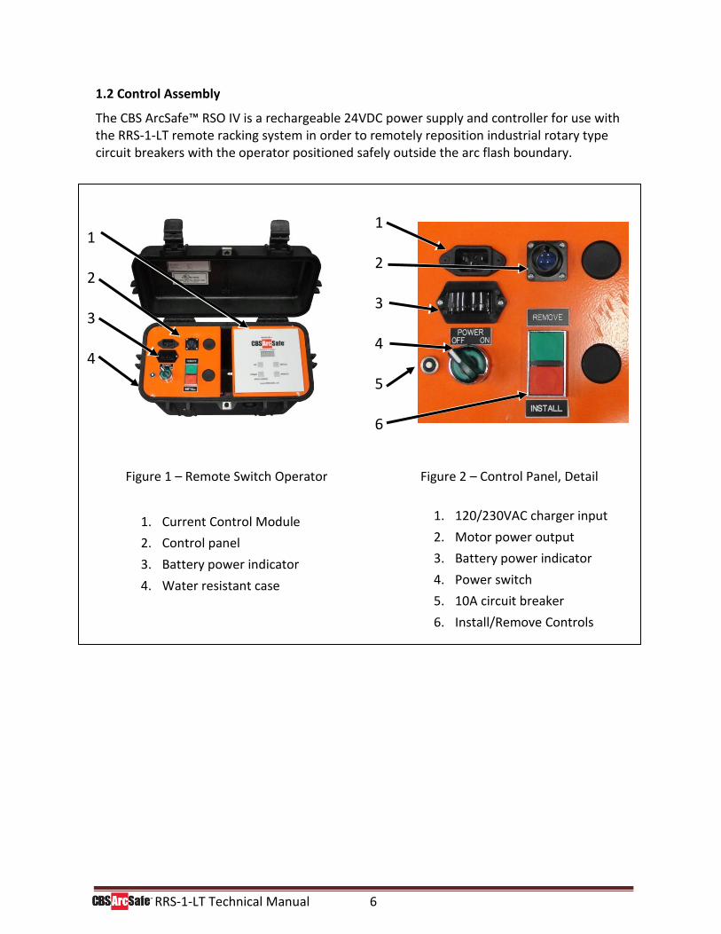
1.2 Control Assembly
The CBS ArcSafe™ RSO IV is a rechargeable 24VDC power supply and controller for use with the RRS-1-LT remote racking system in order to remotely reposition industrial rotary type circuit breakers with the operator positioned safely outside the arc flash boundary.
1 2 3 4
1 2 3 4 5 6
1. Current Control Module
2. Control panel
3. Battery power indicator
4. Water resistant case
1. 120/230VAC charger input
2. Motor power output
3. Battery power indicator
4. Power switch
5. 10A circuit breaker
6. Install/Remove Controls
Figure 1 – Remote Switch Operator
Figure 2 – Control Panel, Detail
RRS-1-LT Technical Manual 7
3.0 Preparation and Setup The preparation and setup of the remote rack is described in the following sections and include:
3.1 Set up Training
This section lists the necessary steps to set up training for your RRS-1-LT.
3.4 Setting the Torque Guard
This section describes the purpose and use of the torque guard.
3.2 Unpacking the RRS-1-LT
This section lists the necessary steps to uncrate the remote rack and prepare it for operational readiness.
3.5 Setting up the RRS-1-LT for Operation
This section lists the preliminary steps for automatic and manual operation.
3.3 Charging the RRS-1-LT
This section describes the procedure for charging the RRS to prepare it for future operations.
3.6 Current Control Module
This section explains the purpose of the current control module and how to use the current control system.
3.1 Set up Training
Included with your purchase of the RRS-1-LT is 4 hours of training from either a CBS ArcSafe® equipment representative or an approved CBS ArcSafe® outside representative. Please call CBS ArcSafe® at (940) 382-4411 to set up this FREE training seminar for your service personnel prior to ANY operations.
DANGER!
*It is VERY important to have proper training before using this unit as improper use may damage your RRS-1-LT or switchgear and void all warranties, written or implied.
RRS-1-LT Technical Manual 8
3.2 Unpacking the RRS-1-LT
The RRS-1-LT is placed in a protected condition to allow the unit to be shipped more efficiently and to prevent damage from occurring. Perform the following steps to unpack the RRS-1-LT and prepare it for operation.
DANGER!
*Do not unpack the RRS-1-LT until your FREE training seminar has been provided. Unpacking the unit before training may void your warranty. This guide is intended for companies that have already received training and are receiving more remote racking systems.
1. Remove the cardboard cover by cutting the perimeter at the base
with a utility knife or removing the nails/screws. 2. Carefully remove the steel strapping that secures the remote rack
to the pallet and roll the unit onto the floor. 3. Inventory the CBS ArcSafe® RRS-1-LT components to ensure
nothing is missing. A CBS ArcSafe® representative will assist with inventory before the FREE training seminar.
4. If pneumatic tires are installed on the unit (optional), ensure the
tires are inflated to their proper pressure of 24 PSI.
5. The CBS ArcSafe® RRS-1-LT is now ready to be charged before the racking operations.
RRS-1-LT Technical Manual 9
3.3 Charging the RRS-1-LT
The CBS ArcSafe® remote racking unit is equipped with batteries to enable operation when AC power is unavailable and even if power is lost the racking operation will continue uninterrupted. Perform the following steps to charge and store the unit to prepare for future operation:
1. Rotate the power switch to the OFF position if not using the RRS-1-LT.
ATTENTION
It is perfectly safe to charge the RRS-1-LT during operations, however if you leave the unit on while storing it the unit will pull unnecessary electricity from the outlet.
2. Connect the RRS-1-LT Power Supply into an AC outlet via the included
power cable.
3. While charging feel free to use the RRS-1-LT in normal operation mode.
4. Whenever possible, leave the CBS ArcSafe® RRS-1-LT plugged in and properly stowed with either the CBS ArcSafe® dust cover or the waterproof cover to ensure the RRS-1-LT is protected until the next operation. Once fully charged the battery charger switches to a ‘Standby Voltage Mode’ maintaining a fully charged battery.
DANGER!
*Storing the RRS-1-LT in freezing temperatures will drastically reduce battery performance, CBS ArcSafe® recommends storing the unit where temperatures are regulated 68˚F to 77˚F. If storage in freezing temperatures is required, contact CBS ArcSafe®.
ATTENTION
At or below 40°F / 5°C we recommend using the AC power supply over the battery power in order for the unit to operate at max power. At temperatures lower than 40°F / 5°C the current provided by the batteries becomes limited and thus may not provide enough racking torque for the installation and/or removal of the breaker.
RRS-1-LT Technical Manual 10
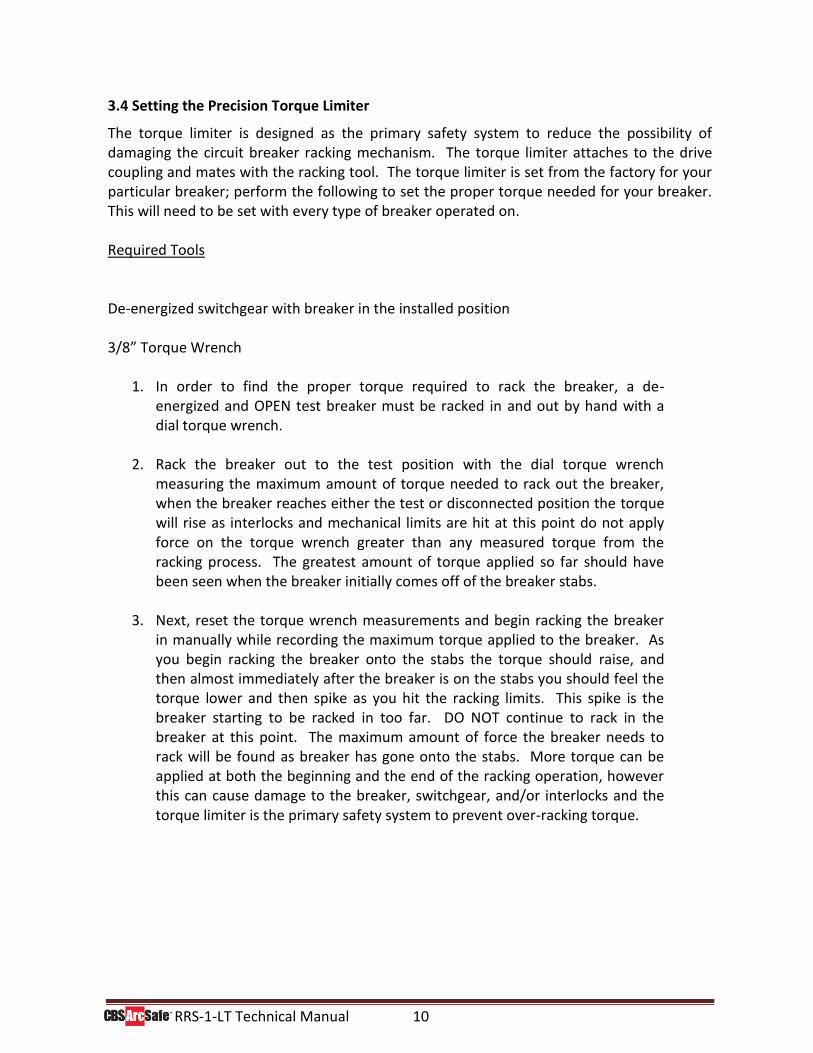
3.4 Setting the Precision Torque Limiter
The torque limiter is designed as the primary safety system to reduce the possibility of damaging the circuit breaker racking mechanism. The torque limiter attaches to the drive coupling and mates with the racking tool. The torque limiter is set from the factory for your particular breaker; perform the following to set the proper torque needed for your breaker. This will need to be set with every type of breaker operated on. Required Tools De-energized switchgear with breaker in the installed position 3/8” Torque Wrench
1. In order to find the proper torque required to rack the breaker, a de-energized and OPEN test breaker must be racked in and out by hand with a dial torque wrench.
2. Rack the breaker out to the test position with the dial torque wrench
measuring the maximum amount of torque needed to rack out the breaker, when the breaker reaches either the test or disconnected position the torque will rise as interlocks and mechanical limits are hit at this point do not apply force on the torque wrench greater than any measured torque from the racking process. The greatest amount of torque applied so far should have been seen when the breaker initially comes off of the breaker stabs.
3. Next, reset the torque wrench measurements and begin racking the breaker
in manually while recording the maximum torque applied to the breaker. As you begin racking the breaker onto the stabs the torque should raise, and then almost immediately after the breaker is on the stabs you should feel the torque lower and then spike as you hit the racking limits. This spike is the breaker starting to be racked in too far. DO NOT continue to rack in the breaker at this point. The maximum amount of force the breaker needs to rack will be found as breaker has gone onto the stabs. More torque can be applied at both the beginning and the end of the racking operation, however this can cause damage to the breaker, switchgear, and/or interlocks and the torque limiter is the primary safety system to prevent over-racking torque.

RRS-1-LT Technical Manual 11
DANGER!
* As breakers age and/or do not see regular maintenance the torque needed to rack
a breaker may increase, however large increases of torque needed to rack a breaker
including amounts over 10% of the average torque may indicate breaker problems.
In many instances breakers that take more torque to rack than similar breakers tend
to have defective mechanics including: broken shutters, defective interlocks, and
malfunctioning racking assemblies. These mechanical issues have been known to
cause an arc flash. Therefore, if the RRS-1-LT does not seem to have enough torque
first double check that the breaker is operating properly before racking out by hand.
When properly set the torque limiter should only slip one tooth when the breaker is either fully installed or removed when using the current control module in automatic mode. If the torque limiter is set too low, the torque limiter will slip excessively during remote racking operation; if this occurs perform the following to adjust the torque limiter level.
1. Attach a torque indicator to the drive head (1) and determine the present torque setting while holding the torque limiter body (5) still.
2. Remove snap ring (2) and locking plate (3).
3. Adjust nut (4) with an open ended wrench
clockwise to increase torque reading, counter-clockwise to decrease torque.
4. Obtain new torque reading with a torque indicator. Replace locking plate and snap ring.
5. Recheck the torque to confirm proper settings.
DANGER!
*Inaccurate setting of the torque listener may result in excessive slip during racking
operations or, if over-tightened, the remote rack placing excessive torque on the
breaker racking mechanism; possibly leading to equipment damage.
1. Drive Head 2. Snap Ring 3. Locking
Plate
4. Nut 5. Body
1
2
3
4
5
RRS-1-LT Technical Manual 12
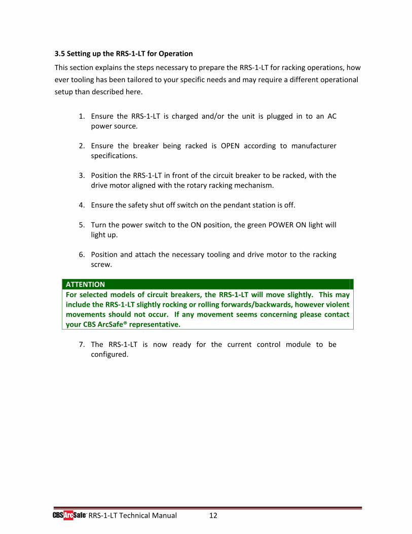
3.5 Setting up the RRS-1-LT for Operation
This section explains the steps necessary to prepare the RRS-1-LT for racking operations, how
ever tooling has been tailored to your specific needs and may require a different operational
setup than described here.
1. Ensure the RRS-1-LT is charged and/or the unit is plugged in to an AC power source.
2. Ensure the breaker being racked is OPEN according to manufacturer
specifications.
3. Position the RRS-1-LT in front of the circuit breaker to be racked, with the drive motor aligned with the rotary racking mechanism.
4. Ensure the safety shut off switch on the pendant station is off. 5. Turn the power switch to the ON position, the green POWER ON light will
light up.
6. Position and attach the necessary tooling and drive motor to the racking screw.
ATTENTION
For selected models of circuit breakers, the RRS-1-LT will move slightly. This may include the RRS-1-LT slightly rocking or rolling forwards/backwards, however violent movements should not occur. If any movement seems concerning please contact your CBS ArcSafe® representative.
7. The RRS-1-LT is now ready for the current control module to be
configured.
RRS-1-LT Technical Manual 13
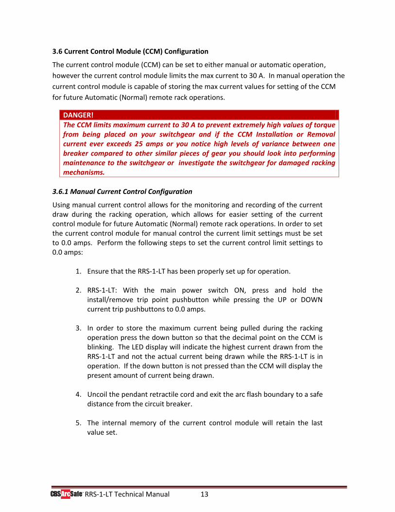
3.6 Current Control Module (CCM) Configuration
The current control module (CCM) can be set to either manual or automatic operation,
however the current control module limits the max current to 30 A. In manual operation the
current control module is capable of storing the max current values for setting of the CCM
for future Automatic (Normal) remote rack operations.
DANGER!
The CCM limits maximum current to 30 A to prevent extremely high values of torque from being placed on your switchgear and if the CCM Installation or Removal current ever exceeds 25 amps or you notice high levels of variance between one breaker compared to other similar pieces of gear you should look into performing maintenance to the switchgear or investigate the switchgear for damaged racking mechanisms.
3.6.1 Manual Current Control Configuration
Using manual current control allows for the monitoring and recording of the current draw during the racking operation, which allows for easier setting of the current control module for future Automatic (Normal) remote rack operations. In order to set the current control module for manual control the current limit settings must be set to 0.0 amps. Perform the following steps to set the current control limit settings to 0.0 amps:
1. Ensure that the RRS-1-LT has been properly set up for operation.
2. RRS-1-LT: With the main power switch ON, press and hold the
install/remove trip point pushbutton while pressing the UP or DOWN current trip pushbuttons to 0.0 amps.
3. In order to store the maximum current being pulled during the racking operation press the down button so that the decimal point on the CCM is blinking. The LED display will indicate the highest current drawn from the RRS-1-LT and not the actual current being drawn while the RRS-1-LT is in operation. If the down button is not pressed than the CCM will display the present amount of current being drawn.
4. Uncoil the pendant retractile cord and exit the arc flash boundary to a safe distance from the circuit breaker.
5. The internal memory of the current control module will retain the last
value set.
RRS-1-LT Technical Manual 14
DANGER!
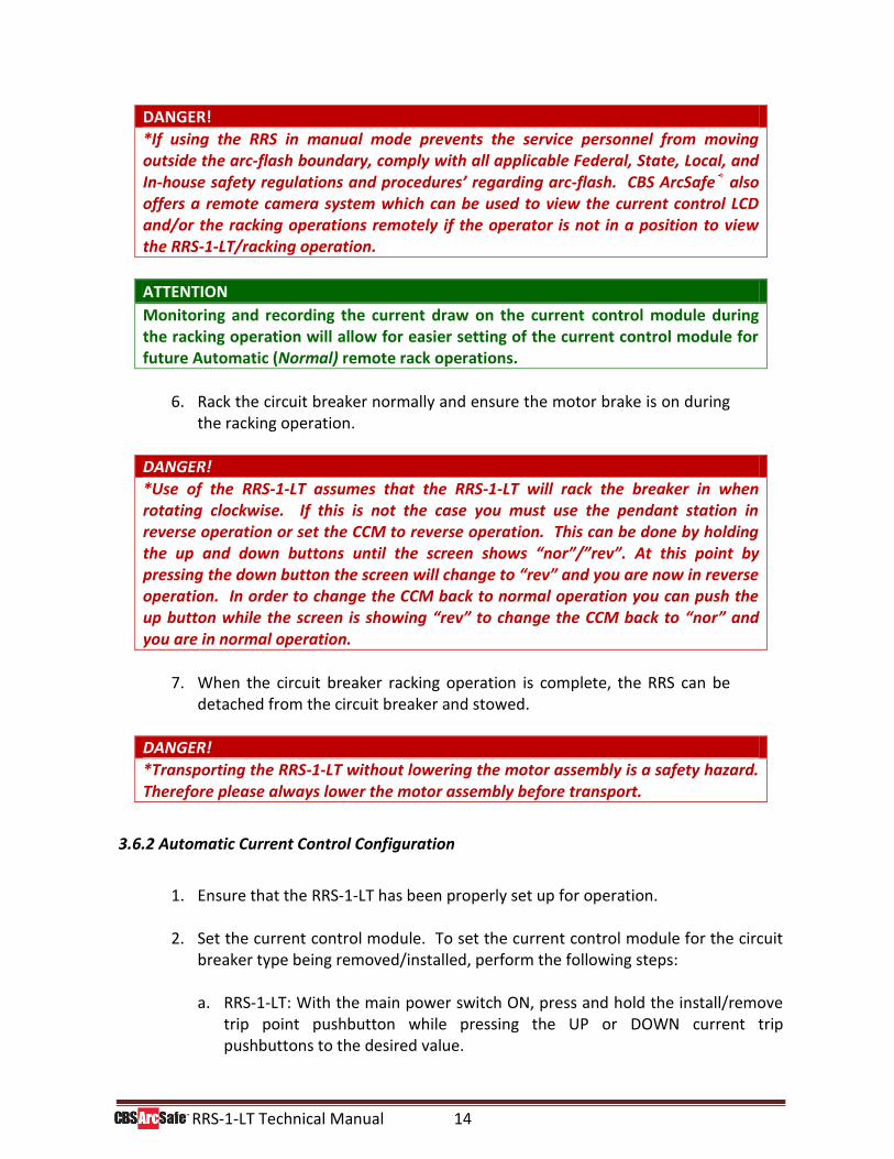
*If using the RRS in manual mode prevents the service personnel from moving outside the arc-flash boundary, comply with all applicable Federal, State, Local, and In-house safety regulations and procedures’ regarding arc-flash. CBS ArcSafe® also offers a remote camera system which can be used to view the current control LCD and/or the racking operations remotely if the operator is not in a position to view the RRS-1-LT/racking operation.
ATTENTION
Monitoring and recording the current draw on the current control module during the racking operation will allow for easier setting of the current control module for future Automatic (Normal) remote rack operations.
6. Rack the circuit breaker normally and ensure the motor brake is on during
the racking operation.
DANGER!
*Use of the RRS-1-LT assumes that the RRS-1-LT will rack the breaker in when rotating clockwise. If this is not the case you must use the pendant station in reverse operation or set the CCM to reverse operation. This can be done by holding the up and down buttons until the screen shows “nor”/”rev”. At this point by pressing the down button the screen will change to “rev” and you are now in reverse operation. In order to change the CCM back to normal operation you can push the up button while the screen is showing “rev” to change the CCM back to “nor” and you are in normal operation.
7. When the circuit breaker racking operation is complete, the RRS can be
detached from the circuit breaker and stowed.
DANGER!
*Transporting the RRS-1-LT without lowering the motor assembly is a safety hazard. Therefore please always lower the motor assembly before transport.
3.6.2 Automatic Current Control Configuration
1. Ensure that the RRS-1-LT has been properly set up for operation. 2. Set the current control module. To set the current control module for the circuit
breaker type being removed/installed, perform the following steps:
a. RRS-1-LT: With the main power switch ON, press and hold the install/remove trip point pushbutton while pressing the UP or DOWN current trip pushbuttons to the desired value.
RRS-1-LT Technical Manual 15
b. The LED display will indicate the reading being set and also display current draw while the RRS-1-LT is in operation.
c. The factory default setting is 0.0 amps.
d. The required current setting is determined by a number of factors including breaker type, size, environment, and physical condition.
e. The best method in determining a suitable current limit setting is operational
experience or by predetermining the current limit by operating the RRS in manual operation the first time a breaker is installed and removed via the remote rack. See the previous section for information.
f. By pushing the Down/Max Current button before running the RRS-1-LT the internal memory of the current control module will retain the largest current values reached during operation. To reset turn the Max Current function off by pressing the button once more and then turning the Max Current function back on.
g. Run the RRS-1-LT
3. Turn the RSO-IV on and exit the arc flash boundary to a safe distance away from
the circuit breaker with the radio remote.
4. Press and release the install pushbutton on the pendant station, the remote racking unit will continue the racking operation until the current draw on the system reaches the current set point. The remote racking can be stopped at any time using the red emergency stop pushbutton on the pendant station; the racking can also be stopped by pressing the opposite remove (install) pushbutton on the pendant station of RRS-1-LT remote racking systems.
DANGER!
*Use of the RRS-1-LT assumes that the RRS-1-LT will rack the breaker in when rotating clockwise. If this is not the case you must use the pendant station in reverse operation or set the CCM to reverse operation. This can be done by holding the up and down buttons until the screen shows “nor”/”rev”. At this point by pressing the down button the screen will change to “rev” and you are now in reverse operation. In order to change the CCM back to normal operation you can push the up button while the screen is showing “rev” to change the CCM back to “nor” and you are in normal operation.
5. If the current control module is set to an accurate level for the switchgear being
operated, the racking operation will stop when the switchgear reaches the DISCONNECT or CONNECTED position and depending on how the breaker racks the RRS-1-LT may also stop at the TEST position automatically.
RRS-1-LT Technical Manual 16
6. When the circuit breaker racking operation is complete, the RRS-1-LT can be detached from the circuit breaker and stowed.
7. Disengage the foot brakes. 8. Remove the circuit breaker racking adapter and any extensions from the breaker
and RRS. 9. Switch the power isolation switch to the OFF position. 10. If applicable, lower the motor assembly, to a suitable position for storage with the
vertical adjustment handle or power slide motor (optional). 11. Cover the RRS-1-LT with the dust cover or the waterproof cover (optional) and
store the unit in a clean, dry location.
3.6.2 Automatic Current Control Time Stop Configuration
One of the key features of using the automatic current control module configuration is being able to change the time stop parameters. This allows for the user to set how long the current can be over the set amount before turning off, anywhere from 0 seconds to .9 seconds in increments of .1 seconds (for versions 2.4 or newer). To set the Time Stop follow the following instructions.
1. Press both the Install and Remove buttons at the same time.
2. Press the Up or Down buttons to set the Time Stop length from 0 seconds - .9
seconds.
ATTENTION
The factory default and recommended setting for normal use is 0.0 seconds.
3. Press either the Install or Remove buttons to exit the Time Stop editing feature,
the Time Stop will be automatically saved.
RRS-1-LT Technical Manual 17
4.0 Operation This section describes the steps necessary to install and remove the circuit breaker using the RRS-1-LT. 4.1 Circuit Breaker Installation/Removal These are the following requirements and steps for circuit breaker installation using the RRS-1-LT. 4.1.1 Requirements for Installation/Removal
The following installation procedure assumes that the following prerequisites have been met:
1. The circuit breaker racking mechanism is in working order. 2. The circuit breaker is installed in the cubicle and OPEN according to
manufacturer specifications.
DANGER!
*For your safety please ensure that all personnel follow the personal protective equipment rules and regulations along with following all of the manufacturer guidelines at ALL times.
DANGER!
*If possible remove control power from the control circuit in order to prevent the accidental closing or tripping of the breaker during the racking procedure.
4.1.2 Steps for Installation/Removal
To install the circuit breaker to the OPERATING position, perform the following steps.
1. Ensure the RRS-1-LT is properly setup using the breaker specific tooling provided.
2. Attach and install the RRS-1-LT unit from the circuit breaker cubicle as follows:
a. Turn the power switch on.
b. Align the motor assembly with the racking mechanism rotary
system using either the vertical adjustment handle or power slide (optional).
c. Attach the circuit breaker racking tooling to the RRS-1-LT and
then attach the RRS-1-LT to the racking mechanism.
RRS-1-LT Technical Manual 18
d. Attach the tether system to the breaker or engage the foot brakes (if required).
e. Turn the motor brake control switch to the ON position.
ATTENTION
The RRS-1-LT motor brake prevents the motor from over rotating and is necessary for most racking operations.
3. Verify the circuit breaker is OPEN according to manufacturer
specifications and company safety policies.
4. Exit the arc flash boundary with the pendant station.
DANGER!
*Exiting the arc flash boundary may prevent the operator from observing the circuit breaker during repositioning, if this situation occurs we recommend acquiring the CBS ArcSafe® camera system in order to remotely view the repositioning. *Although the pendant station allows the operator to be away from the immediate arc flash boundary, personal protective equipment requirements must still be met at all times.
5. To install the breaker use the INSTALL control, REMOVAL for removal,
ensuring the current control module is properly setup and operating in automatic mode if possible.
6. Detach and uninstall the RRS-1-LT unit from the circuit breaker cubicle
as follows:
a. Disengage the foot brakes (optional).
b. Remove the circuit breaker racking tooling and tether kit from the breaker and RRS-1-LT.
c. If applicable, lower the motor assembly, to a suitable position
for storage with the vertical adjustment handle or power slide (optional).
d. Turn the power switch off.
7. Plug in and cover the RRS-1-LT with the dust cover or the waterproof cover
(optional) and store the unit in a clean, dry location.
RRS-1-LT Technical Manual 19
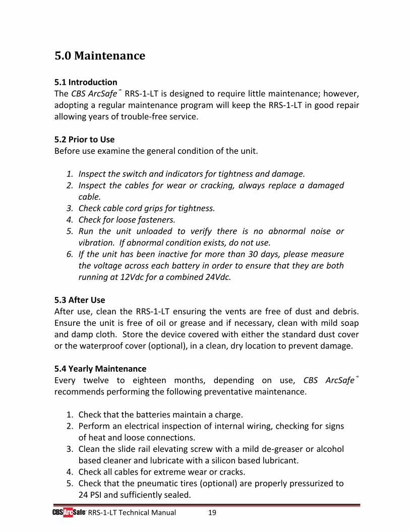
5.0 Maintenance
5.1 Introduction The CBS ArcSafe® RRS-1-LT is designed to require little maintenance; however, adopting a regular maintenance program will keep the RRS-1-LT in good repair allowing years of trouble-free service. 5.2 Prior to Use Before use examine the general condition of the unit.
1. Inspect the switch and indicators for tightness and damage. 2. Inspect the cables for wear or cracking, always replace a damaged
cable. 3. Check cable cord grips for tightness. 4. Check for loose fasteners. 5. Run the unit unloaded to verify there is no abnormal noise or
vibration. If abnormal condition exists, do not use. 6. If the unit has been inactive for more than 30 days, please measure
the voltage across each battery in order to ensure that they are both running at 12Vdc for a combined 24Vdc.
5.3 After Use After use, clean the RRS-1-LT ensuring the vents are free of dust and debris. Ensure the unit is free of oil or grease and if necessary, clean with mild soap and damp cloth. Store the device covered with either the standard dust cover or the waterproof cover (optional), in a clean, dry location to prevent damage. 5.4 Yearly Maintenance Every twelve to eighteen months, depending on use, CBS ArcSafe® recommends performing the following preventative maintenance.
1. Check that the batteries maintain a charge. 2. Perform an electrical inspection of internal wiring, checking for signs
of heat and loose connections. 3. Clean the slide rail elevating screw with a mild de-greaser or alcohol
based cleaner and lubricate with a silicon based lubricant. 4. Check all cables for extreme wear or cracks. 5. Check that the pneumatic tires (optional) are properly pressurized to
24 PSI and sufficiently sealed.
RRS-1-LT Technical Manual 20
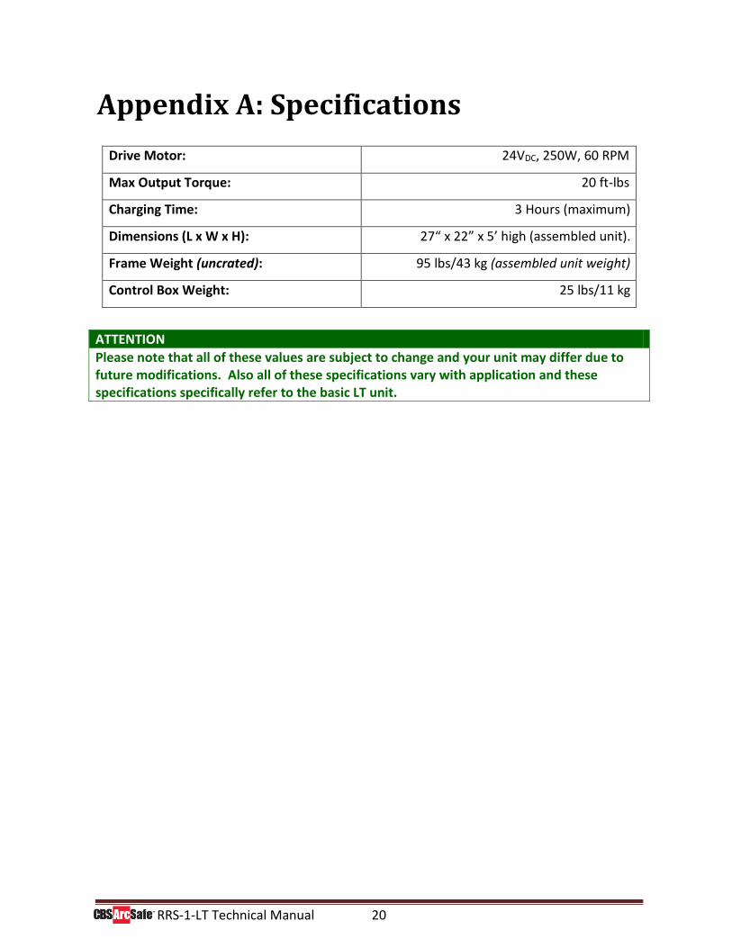
Appendix A: Specifications
Drive Motor: 24VDC, 250W, 60 RPM
Max Output Torque: 20 ft-lbs
Charging Time: 3 Hours (maximum)
Dimensions (L x W x H): 27“ x 22” x 5’ high (assembled unit).
Frame Weight (uncrated): 95 lbs/43 kg (assembled unit weight)
Control Box Weight: 25 lbs/11 kg
ATTENTION
Please note that all of these values are subject to change and your unit may differ due to future modifications. Also all of these specifications vary with application and these specifications specifically refer to the basic LT unit.
RRS-1-LT Technical Manual 21
DANGER! *Ensure that personnel using this equipment are adequately trained in the operation of the switchgear they are planning to work with; that they are correctly stationed outside the arc flash boundary; and that they comply with all applicable Federal, State, Local, and In-house safety regulations and procedures. Attention should be given to distance, angle, and personal protective equipment (PPE).
Guarantee: Equipment is guaranteed free of inherent electrical or mechanical defects for one (1) year from date of shipment, and to perform according to ratings, under normal conditions and with competent supervision. Our obligation is limited to repair or replacement of defective parts, FOB our plant, Denton, TX. We’re not responsible for consequential damage, for repairs or replacement made by others except when agreed to in writing.
P.O. Box 550
Argyle, TX 76226 Tel: 940-382-4411 Fax: 940-382-9435
Website: www.CBSArcSafe.com Email: [email protected]


![USER’S GUIDE &OPERATOR INSTRUCTIONS27].pdf · user’s guide &operator instructions . fetco coffee brewer: cbs-1150 extractor® v+™with bypass . cbs-1151bp-v+ cbs-1152bp-v+](https://img.pdfslide.us/doc/110x75/6006176f3bcf5415eb761a93/useras-guide-operator-instructions-27pdf-useras-guide-operator.jpg)