Embed Size (px)
Citation preview

_____________________________________________________________________________________
r e v . 1 . 0 1 145 Rt. 46 West E‐mail: sales@electro‐set.net Wayne, NJ 07470 Web: www.Electro‐Set.net Tel: (973)689‐9960
1
CB-027 12-Bit A/D Converter Module
September 03, 2014
Introduction
This application note will show two minimal code set ups to operate the 12-bit A/D converter module CB-027 one with an Arduino board and the other with Cardinal’s CB-026 Microchip microcontroller module.
With the jumper inserted on the A/D converter module, the A/D input is connected to an onboard potentiometer allowing the input voltage to be adjusted from 0 volts to 3.3 volts.
Arduino
The Arduino example will read the digital value from the A/D converter and display a decimal value on an LCD display. This value will also be presented to the Arduino serial monitor port.
Before proceeding any further, please have the Arduino software install to your computer. Visit Arduino’s user setup guide at http://arduino.cc/en/Guide/windows for step-by-step instructions.
Hardware
Parts List:
Arduino Uno USB type B connector CB-I-022 Cardinal Interface Board LCD Display (16x2 char. parallel bus) CB-027 A/D converter module

_____________________________________________________________________________________
r e v . 1 . 0 1 145 Rt. 46 West E‐mail: sales@electro‐set.net Wayne, NJ 07470 Web: www.Electro‐Set.net Tel: (973)689‐9960
2
Connect the components as shown in the picture below
Plug your USB connector into to the Arduino board and to computer’s USB port. The computer will supply 5 volts through the USB cable which will be regulated on the Arduino interface board to3.3 volts to run the A/D module.
The Software
#include <Wire.h> // I2C library functions
#include <LiquidCrystal.h> // LCD library functions
#define ADCaddress 0x4D // 7-bits ADCaddress is 0x4D, (8-bits is 0x9A)
_____________________________________________________________________________________
r e v . 1 . 0 1 145 Rt. 46 West E‐mail: sales@electro‐set.net Wayne, NJ 07470 Web: www.Electro‐Set.net Tel: (973)689‐9960
3
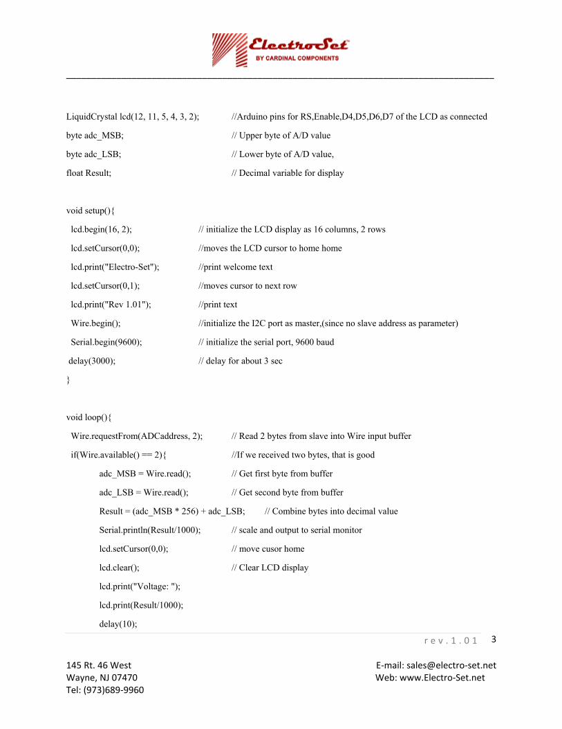
LiquidCrystal lcd(12, 11, 5, 4, 3, 2); //Arduino pins for RS,Enable,D4,D5,D6,D7 of the LCD as connected
byte adc_MSB; // Upper byte of A/D value
byte adc_LSB; // Lower byte of A/D value,
float Result; // Decimal variable for display
void setup(){
lcd.begin(16, 2); // initialize the LCD display as 16 columns, 2 rows
lcd.setCursor(0,0); //moves the LCD cursor to home home
lcd.print("Electro-Set"); //print welcome text
lcd.setCursor(0,1); //moves cursor to next row
lcd.print("Rev 1.01"); //print text
Wire.begin(); //initialize the I2C port as master,(since no slave address as parameter)
Serial.begin(9600); // initialize the serial port, 9600 baud
delay(3000); // delay for about 3 sec
}
void loop(){
Wire.requestFrom(ADCaddress, 2); // Read 2 bytes from slave into Wire input buffer
if(Wire.available() == 2){ //If we received two bytes, that is good
adc_MSB = Wire.read(); // Get first byte from buffer
adc_LSB = Wire.read(); // Get second byte from buffer
Result = (adc_MSB * 256) + adc_LSB; // Combine bytes into decimal value
Serial.println(Result/1000); // scale and output to serial monitor
lcd.setCursor(0,0); // move cusor home
lcd.clear(); // Clear LCD display
lcd.print("Voltage: ");
lcd.print(Result/1000);
delay(10);

_____________________________________________________________________________________
r e v . 1 . 0 1 145 Rt. 46 West E‐mail: sales@electro‐set.net Wayne, NJ 07470 Web: www.Electro‐Set.net Tel: (973)689‐9960
4
}
else{ // if two bytes were not successfully read from module then report “NO DATA”
lcd.setCursor(0,0);
lcd.clear();
lcd.println("NO DATA");
Serial.println("NO DATA");
delay(10);
}
Serial.flush(); // Wait until serial output buffer empty
}
Code Operation
The A/D module has a 7-bit slave address as 0x4d which we make a #define
The LCD library is initialized with the pin connections for RS, Enable, D4, D5, D6 and D7.
The setup() function is called when a sketch starts. The setup code; initializes the LCD display size to 16x2 characters and outputs a welcome message, initializes the I2C port as a master and initializes the serial monitor baud rate at 9600.
After setup has completed the function loop() is repeatedly called.
We read 2 bytes from the A/D module and form them into the float variable ‘Result’. This Result is output to both LCD display and to the serial monitor.
_____________________________________________________________________________________
r e v . 1 . 0 1 145 Rt. 46 West E‐mail: sales@electro‐set.net Wayne, NJ 07470 Web: www.Electro‐Set.net Tel: (973)689‐9960
5
Microchip Module CB-026
The CB-026 example in PICBASIC PRO will read the digital value from the A/D converter and output a decimal value via the serial port to a terminal emulator such as hyperterminal
Before proceeding any further, please have the MicroCode Studio PICBASIC PRO suite installed on your computer.
Hardware
Parts List:
Electro-Set module CB-026 microcontroller USB type mini connector CB-027 A/D converter module
_____________________________________________________________________________________
r e v . 1 . 0 1 145 Rt. 46 West E‐mail: sales@electro‐set.net Wayne, NJ 07470 Web: www.Electro‐Set.net Tel: (973)689‐9960
6
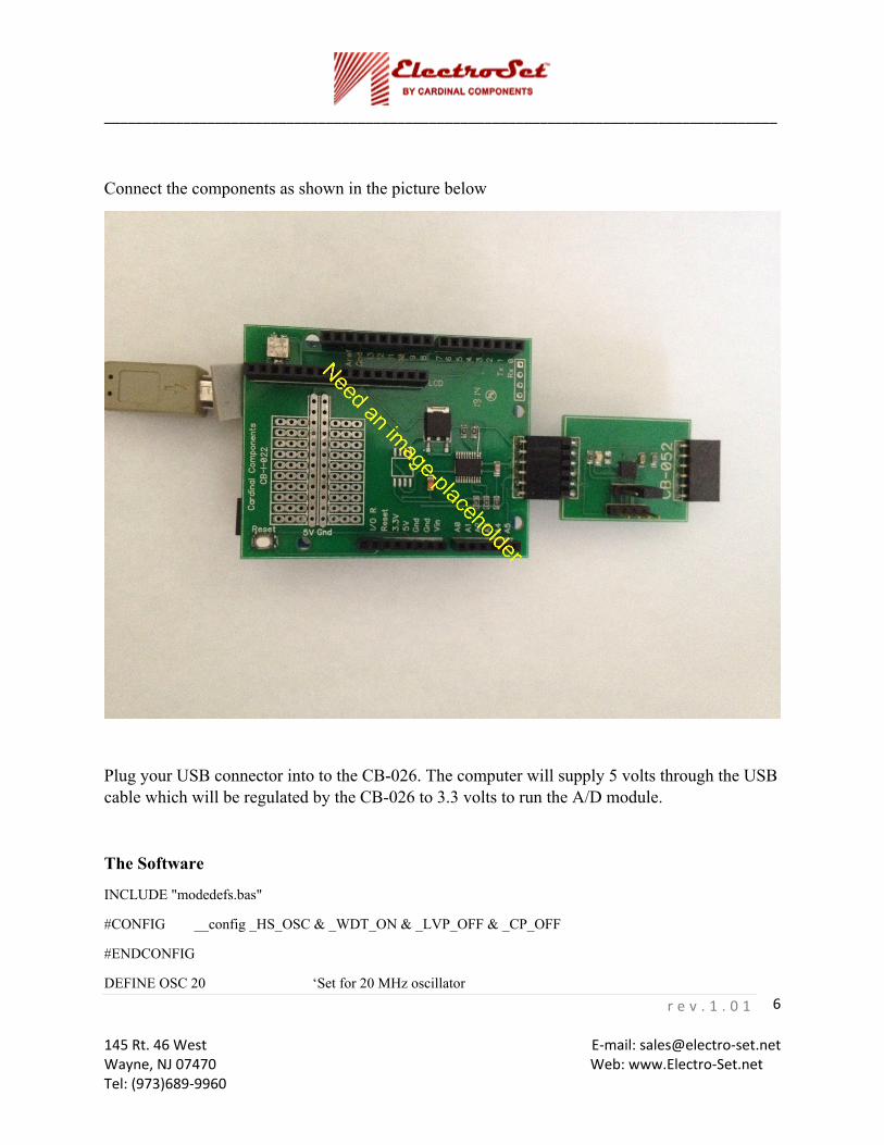
Connect the components as shown in the picture below
Plug your USB connector into to the CB-026. The computer will supply 5 volts through the USB cable which will be regulated by the CB-026 to 3.3 volts to run the A/D module.
The Software
INCLUDE "modedefs.bas"
#CONFIG __config _HS_OSC & _WDT_ON & _LVP_OFF & _CP_OFF
#ENDCONFIG
DEFINE OSC 20 ‘Set for 20 MHz oscillator

_____________________________________________________________________________________
r e v . 1 . 0 1 145 Rt. 46 West E‐mail: sales@electro‐set.net Wayne, NJ 07470 Web: www.Electro‐Set.net Tel: (973)689‐9960
7
SCL var PORTC.3 ‘ Set I2C pins
SDA var PORTC.4
Soutpin var PORTC.6 ‘ Set serial port pins
Sinpin var PORTC.7
baud1 var byte ‘ for serial port baud rate
A_D_Data var byte(2) ‘ To contain two bytes of the A/D convertion
testword var word ‘ 16-bit variable, for combining bytes
baud1 = 6 ‘ 38400 baud, no inversion
ReadAD:
i2cread sda,scl,$9A,$00,[A_D_data(1),a_d_data(2)],nodata ‘ read two bytes from A/D
testword.byte1 = a_d_data(1) ‘ form the two bytes into a word
testword.byte0 = a_d_data(2)
'serout2 soutpin,baud1,[ihex2 a_d_data(1)," ",ihex2 a_d_data(12),13,10] ‘ output the bytes read from the A/D
testword = (testword */ 330)>>4 'Same as ((Testword * 330)/256)/16 ‘ scale testdata for 2 decimal places
serout2 soutpin,baud1,[DEC (TESTWORD/100),".", dec2 testword," Volts",13,10] ; output decimal format
pause 200
goto ReadAD
NoData: ‘ Excute this if the I2C communication fails
Serout2 soutpin,baud1,["A-D Module Not Connected",13,10]
pause 500
goto ReadAD
end

_____________________________________________________________________________________
r e v . 1 . 0 1 145 Rt. 46 West E‐mail: sales@electro‐set.net Wayne, NJ 07470 Web: www.Electro‐Set.net Tel: (973)689‐9960
8
Code Operation
The line
“# CONFIG __config _HS_OSC & _WDT_ON & _LVP_OFF & _CP_OFF”
includes configuration for the programmer in the output hex file so it does not necessary to manually change the entries in the programmer configuration window every time you come to write a new version of your program to the microcontroller.
The port pins for the I2C interface are set on PORTC pins 3 and 4. The CB-026 board wires these to the Electro-Set 6 pin connector.
The microcontroller serial port pins are set on PORTC pins 6 and 7, these connect to the FTDI chip on the CB-026 which couples through to the USB and so when plugged into a PC producing a virtual COMM port where the microcontroller’s serial data can be seen on a terminal emulator such as hyperterminal. The terminal emulator should be set to connect to the virtual COMM port assigned to the FTDI driver and connect at 38400,8,N,1.
We declare the variable baud1 for use in the serout2 to set the baud rate. For a baud rate of 38400, baud1 is set to 6, see the MicroChip documentation for other rates and options.
The first parameters for the PicBasicPro functions i2cread and i2cwrite uses and 8-bit slave address which is a one bit left shift of the 7-bit slave address, so the A/D module’s 8-bit slave address as 0x9A.
The line
i2cread sda,scl,$9A,$00,[A_D_data(1),a_d_data(2)],nodata
reads two bytes from the A/D (slave address 0x9A) at internal register address 0x00 into the two byte variables A_D_data(1) and A_D_data(2). On an error, such as the module is not plugged in, the code will jump to the label ‘nodata’ where the serial port outputs ”A-D Module Not Connected”.
The two bytes are output to the serial port and also used to set the 16-bit word variable ‘testdata’.
Testdata is scaled to represent the voltage measured by the A/D and the resultant value is output to the serial port.
The CB-027 has a potentiometer connected to the analog input which can be adjusted while the code loops. For every code loop the A/D reading is reported on the serial port.