Embed Size (px)
Citation preview

Cavitation growth phenomena in puresliding grease EHD contacts
Article (Accepted Version)
http://sro.sussex.ac.uk
Otsu, Takefumi, Glovnea, Romeo and Joichi, Sugimura (2018) Cavitation growth phenomena in pure-sliding grease EHD contacts. Lubricants, 6 (3). ISSN 2075-4442
This version is available from Sussex Research Online: http://sro.sussex.ac.uk/id/eprint/78407/
This document is made available in accordance with publisher policies and may differ from the published version or from the version of record. If you wish to cite this item you are advised to consult the publisher’s version. Please see the URL above for details on accessing the published version.
Copyright and reuse: Sussex Research Online is a digital repository of the research output of the University.
Copyright and all moral rights to the version of the paper presented here belong to the individual author(s) and/or other copyright owners. To the extent reasonable and practicable, the material made available in SRO has been checked for eligibility before being made available.
Copies of full text items generally can be reproduced, displayed or performed and given to third parties in any format or medium for personal research or study, educational, or not-for-profit purposes without prior permission or charge, provided that the authors, title and full bibliographic details are credited, a hyperlink and/or URL is given for the original metadata page and the content is not changed in any way.
Lubricants 2018, 6, x; doi: FOR PEER REVIEW www.mdpi.com/journal/lubricants
Cavitation growth phenomena in pure-sliding grease 1
EHD contacts 2
Takefumi Otsu1*, Romeo Glovnea2 and Joichi Sugimura3 3 1 Division of Mechatronics, Department of Innovative Engineering, Faculty of Science and Technology, Oita 4
University,700 Dannoharu, Oita, 870-1192, Japan 5 2 Department of Engineering and Design, University of Sussex, United Kingdom 6 3 International Institute for Carbon-Neutral Energy Research, Kyushu University, Japan 7 * Correspondence: [email protected] 8 Received: date; Accepted: date; Published: date 9
Abstract: This article describes experimental and theoretical studies on the cavitation phenomena 10 in the grease lubrication film under pure sliding elastohydrodynamic contact. In-situ observation 11 tests using the optical interferometry technique were conducted, and the growth of cavitation was 12 captured using a high speed camera. The results showed that the cavity grew in two stages, which 13 was similar to the behaviour in the base oil, and that the cavity growth rate in the initial stage was 14 higher than that in the second stage. In the initial stage, the cavity growth time in the grease was 15 longer than that in the base oil, and the cavity length after the growth depended on the base oil 16 viscosity. It was also found in the test using diurea grease that small cavities were formed by the 17 lumps of thickener. The cavity growth in the initial stage was discussed by numerical simulation of 18 pressure distribution based on a simple rheological model. 19
Keywords: Cavitation; Elastohydrodynamic lubrication; Grease; Rheology; Gas 20 21
1. Introduction 22 Cavitation occurs in lubricated contact, and can be detrimental or beneficial to the performance 23
of machine elements 1). The phenomena related to cavitation include cavitation erosion, starvation, 24 breakdown of lubrication film in bearings, which are negative effects, but also reducing friction 25 coefficient and improving seal performance in seals and bearings, which are positive effects. Recently, 26 the cavitation phenomena in the machine elements, such as journal bearing2,3), seal4), pistonring-27 cylinder liner5,6), micro-textured surface7,8), have been studied by the experimental observation and 28 the numerical simulation. 29
One of the negative actions is the inlet starvation which leads to breakdown of lubrication film. 30 Nishikawa et al.9) have shown that short stroke length and/or large frequency, in reciprocated motion, 31 can lead to severe starvation of the contact, due to cavitation. The outlet cavitation also affects the 32 length of the meniscus at the inlet of contact in unidirectional rotating conditions10,11). Severe 33 starvation is caused when the oil is not replenished into opened cavity area which is connected to the 34 atmospheric air, before the next contact. In grease lubrication, the amount of replenishment into the 35 cavity area is even smaller than that in the oil, because of the rheological properties of greases12). A 36 combined, experimental and theoretical analysis of cavitation and fretting wear of a grease lubricated, 37 a point elastohydrodynamic(EHD) contact has been carried out by Leonard et al13). Even at the low 38 velocities characteristic to fretting contacts, they have observed gaseous cavitation, whose length 39 extends with speed. 40
On the other hand, cavitation can reduce the friction coefficient in lubrication film due to lower 41 viscosity resistance force in the cavity region14-16). It has been reported by experimental approaches 42 that cavities formed in the micro pit on the ring surface16) and in the roughness on the rubber surface17) 43 is responsible for (deleted with) reducing the friction coefficient. The relationship between the sealing 44 mechanism and cavitation in lip or face seals is also known as positive actions. Anno and Walowit18) 45

2 of 17
reported that the load capacity on surfaces with micro-asperities is generated when cavitation occurs 46 on the outlet of asperity, because the pressure in the cavitation region is constant and then the positive 47 hydrodynamic pressure is greater than the negative one. This means that the lubrication performance 48 of the sealing surfaces with micro-texture is improved by the formation of cavitation17,19). Cavitation 49 also affects the pressure-induced flow of lubricant, which implies that the leakage of lubricant from 50 the sealing system can be reduced by controlling the cavitation region4). From these facts it can be 51 concluded that, it is important to understand the behaviour of cavitation in various working 52 conditions for accomplishing safe and high performance machine components design. 53
Grease lubrication is widely used in many machine elements and especially rolling element 54 bearings and constant velocity joints, where they are preferred to oil lubrication. They hold important 55 advantages over oil lubricants such as lower lubricant losses, better corrosion protection, improved 56 sealing, easy to handle and the elimination of complex and costly oil supply system. Grease 57 lubrication also has disadvantages, such as poor heat convection which leads to thermal degradation 58 and limited free flow which leads to contact starvation. The complex nature of grease also makes it 59 difficult to predict the film thickness in lubricated contacts from its rheological properties20). Extended 60 studies have been carried out in the past on various aspects of grease-lubricated EHD contacts 61 including the effect of thickener, the base oil and the working parameters21-24). Kauzlarich and 62 Greenwood25) applied the Herschel-Bulckley flow equation to grease lubricated EHD contacts, 63 carrying out a theoretical analysis of film. Yonggang and Jie26) also started from the Herschel-Bulckley 64 model of flow, and introduced a shear rate and time-dependent structural parameter. 65
It is expected that the cavitation phenomenon in grease-lubricated films to be different from that 66 of oil lubrication films because of different rheology and flow properties. Cann et al.27,28) reported that 67 greases do not easily flow back onto the opened cavity area and the rolling track, thus, in the absence 68 of other mechanisms by which the lubricant is brought back in the inlet, severe starvation of the 69 contact occurs. Cavitation phenomena in grease lubrication have yet to be understood, especially the 70 difference between cavitation in the base oil and the grease. Therefore it is important to investigate 71 the cavitation phenomena in grease, for example the effect of rheological behaviour and of the 72 thickener, for the purpose of understanding their effect upon the lubrication performance. 73
One of the characteristics of cavitation is the growth phenomenon29,30). The authors have studied 74 the cavity growth in oil lubricated point contacts in various environments31,32). It has been reported 75 that the cavity grows in two stages; the initial stage in which the cavitation region shows rapid 76 growth and the second stage in which the growth rate is much lower than that in the first stage. The 77 growth in the initial stage is not affected by the amount of dissolved gas in the oil, and the growth 78 relates with the steep pressure drop generated at the outlet of the conjunction. The growth in the 79 second stage depends on the amount of dissolved gas. The cavity length in a gas environment with 80 higher gas solubility is longer, because the amount of released gas into the cavity is affected by the 81 dissolved gas in the oil. It has also been shown in the previous study that this cavity growth model 82 is applied in the high temperature and low pressure conditions33,34). 83
In this study, growth of the cavity in grease lubricated point contacts in pure sliding is 84 investigated. The difference of cavitation phenomena between the grease and the base oil, and the 85 effect of grease composition on the cavity growth are also discussed in this paper. In order to 86 understand the effect of the rheological properties of the greases on cavity growth, a simple numerical 87 analysis was conducted. 88
2. Experimental 89
2.1. Test Apparatus 90 Figure 1 shows a rig for measuring EHD film thickness by optical interferometry used in this 91
study. Greases and their base oils were tested in pure sliding, elastohydrodynamic point contact at a 92 room temperature of 295 K. A plano convex lens was pressed against a rotating disc by a lever, not 93 shown in the figure. The contact between the disc and the lens and the surrounding area were 94

3 of 17
observed through a custom built microscope, and interferometric images of the contact were 95 recorded with a high speed CCD camera. 96
97 Figure 1. Experimental set up. 98
The disc was made of optical glass and had a coating of a semi-reflective chromium layer on the 99 working side. The diameter and thickness of the disc were 80 mm and 8 mm, respectively. The optical 100 interferometry technique with the spacer layer imaging method (SLIM)36) was employed to evaluate 101 the lubricant film thickness, and an additional layer of silica was deposited on top of the chromium 102 coating. The lens was also made out of optical glass and was coated with fully-reflective chromium 103 layer. The radius of curvature of the lens was 10.38 mm. 104
Two series of tests were conducted in this study. The first series consisted of pure sliding tests 105 at 20 mm/s constant speed, in which a load of 1 N (maximum Hertzian pressures of 0.14 GPa, and 106 contact diameter of about 120 µm) was applied to the contact while the disc rotates at a constant speed 107 of 20 mm/s. The second series of experiments were carried out under the accelerating conditions. The 108 speed at the point of contact was increased from rest to 46.5 mm/s, in 17 milliseconds, which gave an 109 acceleration of 2.7 m/s2. In these tests, the load employed was 7 N, which produced a maximum 110 Hertzian pressure of 0.27 GPa, and a contact diameter of about 226 µm. 111
2.2. Greases 112 Five greases were studied in this work. The properties of these greases are shown in Table 1. The 113
base oil of the greases was poly-alpha-olefin (PAO) with various viscosities. Thickeners were lithium 114 stearate, lithium hydroxystarate and diurea. An amount of 0.2 ml of grease was uniformly spread 115 onto the surface of the disc before each test. Grease or oil was not re-supplied into the contact during 116 the tests. 117
118 119 120
4 of 17
Table 1 Properties of greases. 121
No. Thickener Base oil viscosity
@313, 373 K Worked penetration
(Consistency)
Grease 1 Lithium stearate, 12mass% 19, 4.1 [mm2/s] 336
Grease 2 Lithium hydroxystearate, 12mass% 31, 5.8 [mm2/s] 236
Grease 3 Lithium hydroxystearate, 12mass% 66, 10 [mm2/s] 291
Grease 4 Lithium hydroxystearate, 12mass% 411, 41[mm2/s] 386
Grease 5 Diurea, 13.4mass% 31, 5.8 [mm2/s] 280
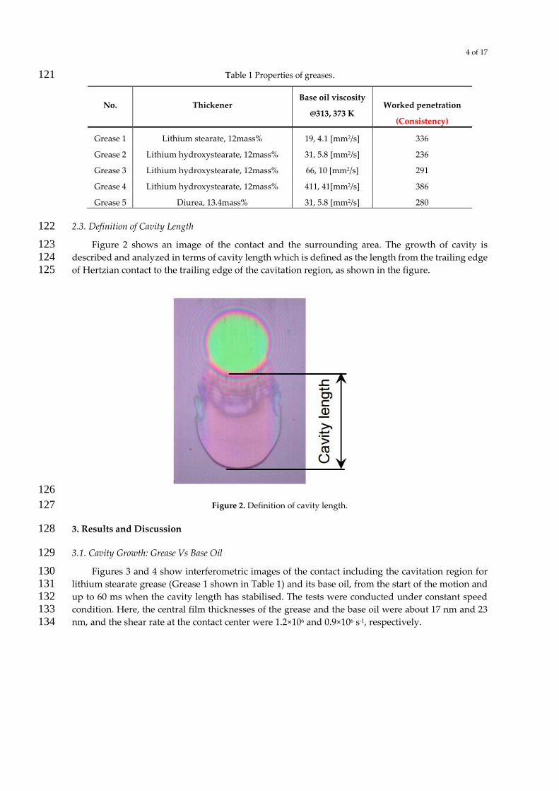
2.3. Definition of Cavity Length 122 Figure 2 shows an image of the contact and the surrounding area. The growth of cavity is 123
described and analyzed in terms of cavity length which is defined as the length from the trailing edge 124 of Hertzian contact to the trailing edge of the cavitation region, as shown in the figure. 125
126 Figure 2. Definition of cavity length. 127
3. Results and Discussion 128
3.1. Cavity Growth: Grease Vs Base Oil 129 Figures 3 and 4 show interferometric images of the contact including the cavitation region for 130
lithium stearate grease (Grease 1 shown in Table 1) and its base oil, from the start of the motion and 131 up to 60 ms when the cavity length has stabilised. The tests were conducted under constant speed 132 condition. Here, the central film thicknesses of the grease and the base oil were about 17 nm and 23 133 nm, and the shear rate at the contact center were 1.2×10⁶ and 0.9×10⁶ s-1, respectively. 134

5 of 17
135 Figure 3. Photographs of cavity in Grease 1 until 60 ms after the start. 136
137 Figure 4. Photographs of cavity in base oil of Grease 1 until 16 ms after the start. 138
Figure 3 clearly illustrates that the cavitation region grows with time. In the image taken at 2 ms 139 the initiation of cavity is observed at the exit of contact. The cavity at times ranging between 2 and 20 140 ms shows the distinctive flower petal-like shape which Dowson et al. 1) referred to as “fingers”. These 141 “petals” appear at the trailing edge of the cavity, and subsequently grow with time. With this type of 142 cavity shape, the gas dissolved in the lubricant is released into the cavity rapidly32). After about 30 ms 143 the cavity shape changes to a rather rounded shape. 144

6 of 17
As seen in Fig. 4 (deleted that) cavity growth for the base oil lubricated contact is similar to that 145 of grease, that is the shape of cavity move after shape shows a petal-like shape, but this changes to 146 monotonic rounded shape after only 10 ms. 147
Figure 5 shows the changes in cavity length with time. The cavity in the grease lubricated contact 148 grows rapidly for the first approximately 30 ms and the growth slows down markedly after that. In 149 the case of the base oil, on the other hand, the cavity length increases rapidly for the first 5 ms at 150 which point the growth rate decreases and cavity length stabilizes at about 10 ms. The growth rates 151 up to 3 ms for the grease and the base oil are 25 mm/s and 20 mm/s, respectively. Thus, in the initial 152 stage of the cavity growth after the initiation, the growth rate is close to the sliding speed of the 153 contact of 20 mm/s for both the grease and the base oil. After this initial stage, the cavity length 154 increases further at different rates, for the two types of lubricants. 155
156 Figure 5. Changes in cavity length from the start to 80 ms for Grease 1 and its base oil. 157
Figure 6 shows images of the cavitation region with lithium stearate grease (Grease 1) and its 158 base oil at later stages from 0.1 s to 1 s. Figure 7 shows changes in cavity length up to one second after 159 the start. Figures 6 and 7 demonstrate that the cavity grows gradually with time. Throughout the 160 second stage, the growth rate of the grease is markedly higher than that in the base oil. 161

7 of 17
162 Figure 6. Photographs of cavity in Grease 1 and its base oil at 0.1, 0.5 and 1s. 163
164 Figure 7. Changes in cavity length from the start to 1s for Grease 1 and its base oil. 165
These results clearly show that the cavity in the grease film grows at two stages32). The initial 166 growth occurs after the initiation of the cavity and takes place at a fast rate approximately equal to 167 the sliding speed of the contact. The growth rates of the grease and the base oil are similar in this time 168 region, but the time for this initial growth is longer for the grease. In the second stage, the cavity 169 grows at a much slower rate, however the growth rate in the grease is still faster than that in the base 170 oil. The details of the mechanism in growth phenomenon will be discussed in the next chapter. 171
3.2. Effect of Base Oil Viscosity 172

8 of 17
In Fig.8, the changes in the cavity length with time is shown for three lithium hydroxystearate 173 greases with different base oil viscosity, 31, 66, and 410 mm2/s at 313K (Grease 2, 3 and 4). The tests 174 were conducted under constant speed condition. For comparison, changes of cavity length for the 175 base oils are also shown. 176
The rate of cavity growth soon after the start is similar for greases with different base oil 177 viscosity, but the duration in the initial stage is different; the time is longer for greases with higher 178 base oil viscosity. At 60 ms after the initial growth, the cavity length is longer for greases with higher 179 viscosity. Figure 8 also indicates that the cavity length at 60 ms for the base oil is shorter than that in 180 the grease, while the growth rate in the initial stage is almost same for all the base oils and greases. 181 Otsu35) previously found that the cavity region in the initial stage was affected by the negative 182 pressure generated at the outlet of the contact, and the cavity length increased with the viscosity 183 because the negative pressure depends on the viscosity. Stadler et al. 37) also reported the relationship 184 between the cavity length and the negative pressure. This behaviour is almost the same as that found 185 for the grease in this study. This suggests that the growth time increases with base oil viscosity 186 because the negative pressure region is larger for higher viscosity, and this holds also for the greases. 187
188 Figure 8. Effect of base oil viscosity on cavity growth for Grease 2, 3 and 4. 189
3.3. Effect of Thickener 190 Lithium hydroxystearate grease (Grease 2) and diurea grease (Grease 5) have been selected to 191
study the effect of the thickener. Cavity growth under the accelerating condition was observed in this 192 study. 193
Figure 9 shows images of the cavity for the two greases. As it can be seen in these images, the 194 cavity length changes from the start of the motion for both greases, but the shape of the cavitation 195 region is different. For the lithium hydroxylstearate grease, the cavity shape is similar to that found 196 for the base oil. This is obvious when comparing with the image taken at 7 ms shown in Fig. 3. In 197 both cases, a number of petal-like projections appear at the trailing edge of the cavity. On the other 198 hand, a number of cavities are formed by lumps of thickener soon after the start of the motion for 199 diurea grease. It can be seen that pocket cavities are formed not only at the edge of contact, but also 200 at other positions in the outlet region of the contact. Each of these individual cavities grow with time. 201 At 14 ms these cavities have merged to form a single, larger cavity. Figure 10 shows the change of the 202 cavity length with time. The variation of the sliding speed in these tests is also shown in Fig. 10. As it 203 can be seen, (deleted that) the cavity length in diurea grease suddenly changes at 9 ms due to the 204 merger of smaller cavities. 205
206

9 of 17
207 Figure 9. Cavity growth in Grease 2 and Grease 5. 208
209 Figure 10. Changes in cavity length during acceleration regime for Grease 2 and Grease5. 210
These results show that dispersion of the thickener in grease affects the formation of cavity. 211 Negative pressure is generated behind the thickener lumps, resulting in small cavities formed 212 partially at the outlet of contact. These small cavities may grow to a larger final cavity in some cases. 213
4. Cavity Growth Model in Grease Lubricated Contact 214
4.1. Two Stage of Cavity Growth 215 Figure 11 shows a schematic of the two-stage cavity growth revealed in this study. The results 216
in section 3.1 shows that initial growth is faster than the growth in the second stage, and that duration 217

10 of 17
of the initial stage in the grease is longer than that in the base oil. The time of initial growth is longer 218 for the grease with higher base oil viscosity, as shown in section 3.2. 219
220 Figure 11. Cavity growth in two stages. 221
A similar trend of the cavity growth was found for oil lubricants32,35). Otsu et al. 32) reported that, 222 in the initial stage, cavity growth was related with the steep pressure drop at the exit of the EHD 223 contact; dissolved gas was released rapidly because the pressure at outlet of contact drops to the 224 saturation pressure of the gas. They also explained the mechanism in the initial stage by using a 225 simple theoretical model. In the second stage, the cavity growth was caused mainly by the dissolved 226 gas which was transferred to the cavity at cavity-lubricant boundary by the difference in the 227 concentration, thus the cavity length increased gradually with time. These suggest that, in grease 228 lubricated contact, the viscosity of grease and the amount of dissolved gas in the grease are the cause 229 of the difference in the cavity growth between the grease and the base oil. 230
In the initial stage, the negative pressure distribution at the exit of the contact depends on the 231 viscosity of the lubricant if the sliding speed and the shape of the gap are the same. As the viscosity 232 of greases depend on shear rate, and should be greater than that of the oil, the pressure distribution 233 should be different from that of the base oil. For greases with higher viscosity, the time of the initial 234 stage of cavity growth should be longer because the pressure drop at the exit of contact is larger. 235 Therefore, it would be worth extending the previous theoretical model to grease lubricated contacts 236 by introducing the rheological properties of greases to see if these assumptions are correct. In 237 addition, in case of diurea greases cavities are formed behind the thickener lumps, as shown in 238 chapter 3.3. This reveals that, in the initial stage, the negative pressure distribution partially changes 239 due to thickener lumps passing through the contact. 240
In the second stage, the previous study 35) showed that the cavity growth in greases was different 241 for different surrounding gas and the length increased with increasing the gas solubility in the base 242 oil. This implies that the cavity growth in greases occurred by the release of dissolved gas into cavity 243 just as in the oil lubricated contact. In the present study, the experiments shown in section 3.1 244 demonstrate that the cavity growth in the second stage is larger than that for the base oil. This 245 suggests that the amount of dissolved gas in the grease is higher than that in the base oil. Another 246 possible mechanisms for the larger cavity in the second stage in greases may be related with the 247 replenishment capability of grease into cavity region. These two points will be addressed in future 248 work. 249
4.2. Simple Numerical Analysis for Initial Stage of Cavity Growth 250 In order to understand the cavity growth in the initial stage, the simple theoretical analysis32) is 251
extended here to grease lubricated contacts. In this analysis, a parametric study with model greases 252

11 of 17
is made in order to qualitatively understand the cavity growth with Grease 1 and its base oil shown 253 in section 3.1. Pressure distribution in the divergent region of the conjunction is calculated by 254 considering the viscosity of greases, and the relation between the negative pressure and cavity 255 growth is discussed. 256
The shear dependence of the viscosity of greases is described here by the following simple 257 equation: 258
121
−+= mCC γη (1)
where η is viscosity, γ is shear rate, C1, C2 and m are constants which determine the rheological 259 behaviour of the fluid. In the case where C1 and C2 are not zero and m is equal to zero, Equation (1) 260 corresponds to a Bingham plastic material. According to Sakurai and co-workers38), greases typically 261 have C1 equal to base oil viscosity and m = 0.2, while m = 0.5 for a softened grease. For oils, C2 is zero, 262 thus it is assumed that their viscosity does not depend on the shear rate. In this analysis, 0.04 Pa・s 263 is used for C1 for the viscosity of the base oil of Grease 1 at 295K, and five values of C2, that is 0, 10, 264 100, 150 and 200, are chosen. Index m was taken as 0.2, as suggested by Sakurai, thus the viscosity of 265 grease used in the test shown in section 3.1, is given by: 266
8.02
121 04.0 −− +=+= γγη CCC m (2)
Figure 12 illustrates the relationship between the viscosity and the shear rate given by Eq.(2). 267 The viscosity of the grease decreases with the shear rate, and the value reaches to the base oil viscosity 268 at high shear rate, of about at 106 s-1 which corresponds towards the value in lubrication film shown 269 in the results in section 3.1. 270
271 Figure 12. Relationship between viscosity and shear rate. 272
The pressure distribution at the outlet of the cavity region is evaluated by numerical calculation 273 of the pressure given by Equation (3). Details of the derivation of this relationship are shown in the 274 appendix. 275
−+
−= ∫∫∫ ∫ ++
+ xx nm
xx n
nxx
xxm dx
hhdx
hUCdx
hhdx
hUCp
111 1 321
2321116116 (3)
In this equation, h is the separation between the solid surfaces, hm is the separation corresponding 276 to the local extreme value of the pressure and n has the value -0.8. 277

12 of 17
Figure 13 shows the pressure distribution at zero second for the base oil and three model greases 278 with different C2. It clearly demonstrates that the region of absolute zero pressure, -0.1 MPa, is larger 279 for the grease with higher C2. This is caused by higher viscosity. 280
281 Figure 13. Effect of C2 on negative pressure distribution. 282
Otsu et al. 32,35) reported that the cavity length after the initial growth is close to the length of -0.1 283 MPa negative pressure region at zero second. This means that C2 can be predicted by comparing the 284 cavity length in the test and the calculated length of negative pressure region. Figure 13 shows that 285 the length of -0.1 MPa region for C2 of 150 is about 500 µm and this value is close to the cavity length 286 after the initial growth of 450-470 µm, as shown in Fig.5. Thus, 150 is assumed to correspond to the 287 value of C2 for Grease 1. 288
Figures 14, 15 and 16 show the variation with time of the calculated pressure distribution for the 289 base oil and for the grease with C2=150, respectively. The viscosity of the oil, sliding speed and film 290 shape are the same with the values in the experiments, while the film thickness measured by the 291 optical interferometry is used as hmin. 292
293 Figure 14. Changes in pressure distribution with time in base oil of Grease 1. 294

13 of 17
295 Figure 15. Changes in pressure distribution with time in grease with C2=150. 296
297 Figure 16. Changes in pressure distribution until 70 ms in grease with C2=150. 298
In the pressure distribution, the -0.1 MPa region at zero s governs the initiation of cavity. Figures 299 14 and 15 clearly demonstrate that the length of the -0.1 MPa region is larger in the grease than in the 300 base oil. Also, the region of -0.1 MPa extends until 10 ms after the start for the grease and only until 301 3 ms for the oil, which is similar with the time for the rapid cavity growth shown in the experiments 302 in section 3.1. These figures also demonstrate that the pressure increases with time as the cavity grows 303 with time, and that the pressure distribution in the grease and the oil does not substantially change 304 after 55 ms and 10 ms, respectively. 305
Figure 17 shows the changes in the maximum negative pressure and the cavity length with time 306 for the base oil and the grease. In this figure, changes of the cavity length are for the test results of 307 Grease 1 and the base oil in section 3.1. All these figures demonstrate that rapid cavity growth occurs 308 when pressure drop is steeper and this happens for both the grease and oil. The cavity growth time 309 in the initial stage for the grease is longer because the steep pressure drop continues longer than for 310 the oil. This suggests that the difference in the cavity growth is caused by different rheological 311 properties. The shear rate dependence of the viscosity works to cause different growth behaviours. 312

14 of 17
313 Figure 17. Relation between minimum pressure and cavity growth for the grease and its base oil. 314
5. Conclusions 315 Cavitation in grease-lubricated EHD contacts has been studied with the optical interferometry 316
technique. The following conclusions are drawn from this study. 317 (1) Two stage cavity growths were observed in grease films, which is similar to those in the base 318
oil. The cavity growth rate in the initial stage is higher than that in the second stage, and the growth 319 time of the initial stage for the grease is longer than that for the base oil. 320
(2) The cavity length for greases is almost the same as that for their base oil up to 3 ms after the 321 start of sliding, but is longer than that in the base oil after 3 ms under the present test conditions. 322
(3) The growth time of the initial stage is longer for higher base oil viscosity. After the growth in 323 the initial stage, the cavity length for greases with higher base oil viscosity is longer. 324
(4) In diurea grease, lumps of thickener cause the formation of smaller, individual cavities 325 immediately after the start. 326
(5) A theoretical analysis with a simple rheological model shows that the negative pressure 327 (below ambient) region in grease lubricated contacts is greater than that for the base oil, which 328 qualitatively agrees with the experimental results. The analysis suggests that the cavity growth in the 329 initial stage is related to steep pressure drop and its relaxation. 330 Acknowledgements: The authors express their gratitude to NSK Ltd. for supplying the greases. 331
Appendix 332 Consider the geometry of downstream of the contact between the ball and the disc at the exit 333
region, beyond the exit constriction, as illustrated in Figure A126). 334
335 Figure A1. Geometry of the exit region of contact. 336

15 of 17
The separation between the surfaces h can be expressed by the relationship 39): 337
))1(cos)2(( 5.02
21
2
22
min −+−−+= −
ax
xa
ax
Rahhπ
(A1)
where a is the radius of the contact area and R the reduced radius of curvature of the surfaces. 338 It is obvious that the shear rate, defined as hU /=γ is not constant in this region, and according 339
to Equation (A1) the viscosity of the lubricant is assumed to vary with the position from the contact. 340
n
hUCC
+= 21η (A2)
The 2-D Reynolds equation is as follows: 341
36h
hhUdxdp m−
= η (A3)
where η is a function of h and implicitly of x. 342 By substituting (A1) and (A2) in (A3), separating the variables and integrating yield the 343
following expression for the pressure. 344
3321
2321111 1
116116 Cdxh
hdxh
UCdxh
hdxh
UCp xx nm
xx n
nxx
xxm +
−+
−= ∫∫∫ ∫ ++
+ (A4)
where C3 is a constant of integration. x1 is a + lc, where a is radius of the Hertzian contact area and lc is 345 cavity length, if the axis x is taken from the center of the Hertzian contact, x2 is the position of the end 346 of fully flood zone32). 347
As boundary conditions, the pressure at x1 and x2 is assumed to be zero. C3 and hm can be obtained 348 as follows: 349
C3 = 0 (A5)
( ) ( )
( ) ( )∫∫
∫∫
+
+
+
+=
2
1
2
1
2
1
2
1
3231
2221
11
11
xx n
nxx
xx n
nxx
m
dxxh
UCdxxh
C
dxxh
UCdxxh
Ch (A6)
It follows that the pressure distribution is described by the following equation (A7). 350
( )
−+
−= ∫∫∫ ∫ ++
+ xx nm
xx n
nxx
xxm dx
hhdx
hUCdx
hhdx
hUCxp
111 1 321
2321116116 (A7)
References 351
1. Dowson, D., Godet, M. and Tayler, C.M., “Cavitation and Realated Phenomena in Lubrication”, 1975, 352 Mechanical Engineering Publications Ltd. 353
2. Sakai, F., Ochiai, M. and Hashimoto, H., “CFD Analysis of Journal Bearing with Oil Supply Groove 354 Considering Two-Phase Flow”, Proceedings of the 4th International Conference on Design Engineering and 355 Science, ICDES 2017, 2017, 131. 356
3. Otsu, T. and Nishida, K., “Growth of Cavitation in Journal Bearing and Effect of Cavitation on Behavior of 357 Bearing”, Journal of Japanese Society of Tribologists, 2016, 61, 2, pp. 127-136 (in Japanese). 358
4. Tokunaga Y., Sugimura, J. and Yamamoto, Y., “Development and Performance Verification in Mechanical 359 Seals with Friction Reduction and Sealing Mechanism -Experimental Study-”, Journal of Japanese Society 360

16 of 17
of Tribologists, 2015, 60, 5, pp. 332-341 (in Japanese). 361 5. Vasilakos, I., “Cavitation in the Cylider-liner and Piston-ring Interaction in Internal Combustion Engines”, 362
PhD thesis of City, University of Lindon, 2017. 363 6. Tang, T., Morris, N., Coupland, J. and Arevalo, L., “Cavitation Bubble Measurement in Tribological 364
Contacts Using Digital Holographic Microscopy”, Tribology Letters, 2015, 58, 5, pp. 1-10. 365 7. Shen, C. and Khonsari, M.M., “On the Magnitude of Cavitation Pressure of Steady-State Lubrication”, 366
Tribology Letters, 2013, 51, pp. 153-160. 367 8. Yagi, K., Sato, H. and Sugimura, J., “On the Magnitude of Load-Carrying Capacity of Textured Surfaces in 368
Hydrodynamic Lubrication”, Tribology Online, 2015, 10, 3, pp. 232-245. 369 9. Nishikawa, H., Handa, K. and Kaneta, M., “Behaviour of EHL Films in Reciprocated Motion”, JSME 370
International Journal., 1995, 38, 3, pp. 558-567. 371 10. Pemberton, J. and Cameron, A. A., “A Mechanism of Fluid Replenishment in Elstohydrodynamic Contacts”, 372
Wear, 1976, 37, pp. 185-190. 373 11. Jackson, A. and Cameron, A., “An Interferometric Study of the EHL of Rough Surfaces”, ASLE Transaction, 374
1976, 19, 1, pp. 50-60. 375 12. Cann, PME., “Thin-film Grease Lubrication”, Proceedings of Institution of Mechanical Engineers, 1999, 213, 376
Part J., pp. 405-416. 377 13. Leonard, B., Sadeghi, F. and Cipra, R., “Gaseous Cavitation and Wear in Lubricated Fretting Contacts”, 378
Tribology Transaction, 2008, 51, 3, pp. 351-360. 379 14. Etsion, I., Halperin, G., Brizmer, V. and Kligerman, Y., “Experimental Investigation of Laser Surface 380
Textured Parallel Thrust Bearings”, Tribology Letters, 2004, 17, 2, pp. 295-300. 381 15. Ryk, G., Kligerman, Y., Etsion, I. and Shinkarenko, A., “Experimental Investigation of Partial Laser Surface 382
Texturing for Piston-ring Friction Reduction”, Tribology Transaction, 2005, 48, pp. 583-588. 383 16. Yagi, K., Takedomi, W., Tanaka, H. and Sugimura, J., “Improvement of Lubrication Performance by Micro 384
Pit Surfaces”, Tribology Online, 2008, 3, 5, pp. 285-288. 385 17. Sato, Y., Seki, K., Sugimura, J. and Yamamoto, Y., “Experiments and Simple Modelling of Hydrodynamic 386
Lubrication in Radial Shaft Seals”, Proceedings of the 17th international conference of fluid sealing, BHR 387 group, 2003, pp. 139-156. 388
18. Nau, B.S., “Film Cavitation Observation in Face Seals”, Proceedings of the 4th International conference on 389 fluid sealing, BHRA, 1969, pp. 190-198. 390
19. Anno, J.N. and Walowit, J.A., “Microasperity Lubrication”, Journal of lubrication Technology, 1968, pp. 391 351-355. 392
20. Sisko, A.W., “The flow of lubricating greases”, Industrial and Engineering Chemistry, 1958, 50, 12, pp. 1789-393 1792. 394
21. Dyson, A. and Wilson, A.R., “Film Thickness in Elastohydrodynamic Lubrication of Rollers by Greases”, 395 Proceedings of Institution of Mechanical Engineers, 1970, 184, pp. 1-11. 396
22. Kaneta, M., Ogata, T., Takubo, Y. and Naka, M., “Effects of a Thickener Structure on Grease 397 Elastohydrodynamic Lubrication Films”, Proceedings of Institution of Mechanical Engineers, 2000, 214, 398 Part J., pp. 327-336. 399
23. Couronné, I., Mazuyer, D., Vergne, P., Truong-Dinh, N. and Girodin, D., “Effects of Grease Composition 400 and Structure on Film Thickness in Rolling Contact”, Tribology Transaction, 2003, 46, 1, pp. 31-36. 401
24. Eriksson, P., Wikstroèm, V. and Larsson, R., “Grease Passing Through an Elastohydrodynamic Contact 402 under Pure Rolling Conditions”., Proceedings of Institution of Mechanical Engineers, 2000, 214, Part J., pp. 403

17 of 17
309-316. 404 25. Kauzlarich, J. and Greenwood, J.A., “Elastohydrodynamic Lubrication with Herschel-Bulckley Model 405
Greases”, ASLE Transaction, 1972, 15, 4, pp. 269-277. 406 26. Yanggang, M. and Jie, Z., “A Rheological Model for Lithium Lubricating Grease”, Tribology International, 407
1998, 31, 10, pp. 619–625. 408 27. Cann, P.M.E., “Starved Grease Lubrication of Rolling Contacts”, Tribology Transaction, 1999, 42, pp. 867-409
873. 410 28. Hurley, S., Cann, P.M. and Spikes, H.A., “Lubrication and Reflow Properties of Thermally Aged Greases”, 411
Tribology Transaction., 2000, 43, 2, pp. 221-228. 412 29. Dowson, D., “Investigation of Cavitation in Lubricating Films Supporting Small Loads”, Proceedings of 413
Conference on Lubrication and wear, 1957, pp. 93-99. 414 30. Archard, J.F. and Kirk, M.T., “Influence of Elastic Modulus on the Lubrication of Point Contacts”, 415
Lubrication and Wear Convention, 1963, paper 15, pp. 181-189. 416 31. Otsu, T., Tanaka, H., Izumi, N. and Sugimura, J., “Effect of Surrounding Gas on Cavitation in EHL”, 417
Tribology Online, 2009, 4, 2, pp. 50-54. 418 32. Otsu, T., Tanaka, H. and Sugimura, J., “Initiation and Growth of Gaseous Cavity in Concentrated Contact 419
in Various Surrounding Gas”, Tribology International, 2012, 53, pp. 68-75. 420 33. Otsu, T., Tanaka, H. and Sugimura, J., “Effect of Temperature on Growth of Gaseous Cavitation in Point 421
Contact EHL”, Journal of Japanese Society of Tribologists, 2014, 59, 10, pp. 648-656 (in Japanese). 422 34. Otsu, T., Tanaka, H. and Sugimura, J., “Effect of Surrounding Pressure on Cavity Growth in EHD contact”, 423
Proceeding of International Tribology Conference Hiroshima 2011, 2011, E4-07. 424 35. Otsu, T., “Study on Cavitation in Elastohydrodynamic Lubrication”, PhD thesis of Kyushu University, 2012 425
(in Japanese). 426 36. Cann, PM, Hutchinson, J. and Spikes H.A., “The Development of a Spacer Layer Imaging Method (SLIM) 427
for Mapping Elastohydrodynamic Contacts”, Tribology Transaction, 1996, 39, pp. 915-921. 428 37. Stadler, K., Izumi, N., Morita, T., Sugimura, J. and Piccigallo, B., “Estimation of Cavity Length in EHL 429
Rolling Point Contact”, ASME Transaction, Journal of Tribology, 2008, 130. 430 38. Sakurai, T., Hoshino, M. Tokashiki, M. and Fujita, M., “Grease for lubrication and synthetic lubricant”, 1983, 431
Saiwai-syobou, pp. 80 (in Japanese). 432 39. Wedeven, L.D., Evens, D. and Cameron, A., “Optical analysis of ball bearing starvation”, Transaction of 433
ASME, Journal of Lubrication Technology, 1971, 93, pp. 349-363. 434