Embed Size (px)
Citation preview
Causes of Transverse Cracking in Concrete Bridge Decks
Yaohua Deng (Jimmy), Ph.D., PEBrent M. Phares, Ph.D., PE
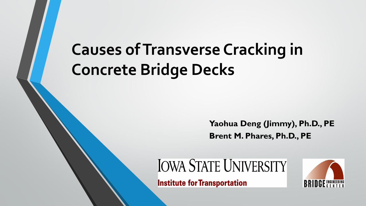
BackgroundTransverse bridge deck cracking:
• Occurs shortly after construction
• Prior to traffic placed on the bridge
• Confusing as, sometimes occurs in only one of twin, side-by-side bridges
Background
Problems associated with transverse bridge deck cracking:
• Allowing the intrusion of water and chlorides
• Causing accelerated concrete deterioration
• Reducing bridge deck service life
Background
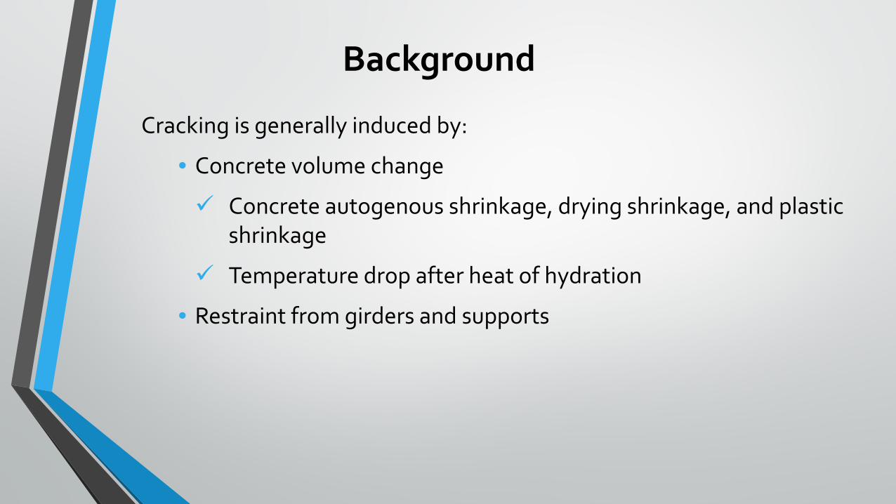
Cracking is generally induced by:
• Concrete volume change
Concrete autogenous shrinkage, drying shrinkage, and plastic shrinkage
Temperature drop after heat of hydration
• Restraint from girders and supports
Background
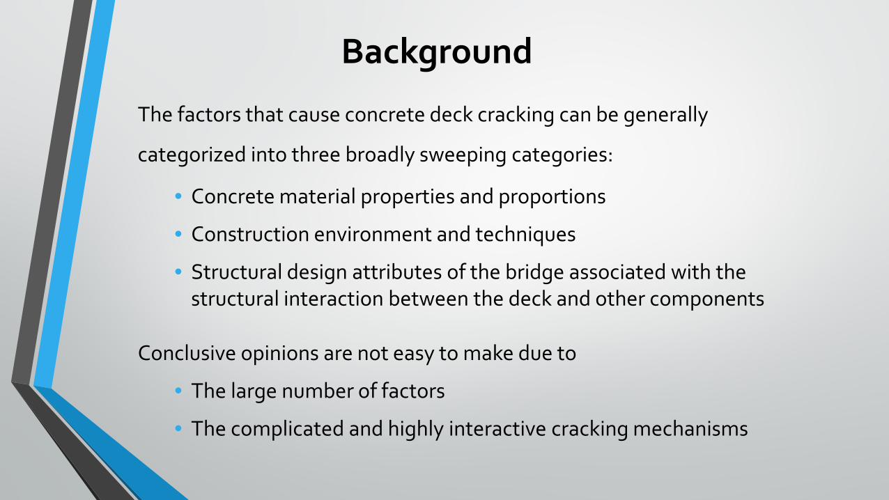
The factors that cause concrete deck cracking can be generally
categorized into three broadly sweeping categories:
• Concrete material properties and proportions
• Construction environment and techniques
• Structural design attributes of the bridge associated with the structural interaction between the deck and other components
Conclusive opinions are not easy to make due to
• The large number of factors
• The complicated and highly interactive cracking mechanisms
Objectives
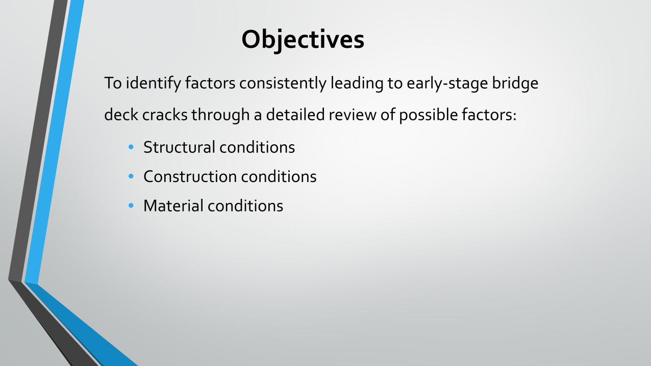
To identify factors consistently leading to early-stage bridge
deck cracks through a detailed review of possible factors:
• Structural conditions
• Construction conditions
• Material conditions

Work plan
Task 1 – Literature review
Task 2 – Investigation of factors leading to cracking
• Step 1 Review and field visits
• Step 2 Structure, construction & Material
• Step 3 Analysis
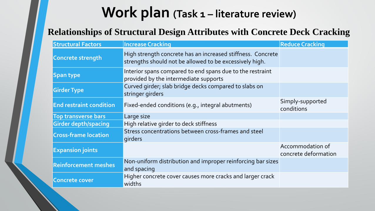
Work plan (Task 1 – literature review)
Structural Factors Increase Cracking Reduce Cracking
Concrete strengthHigh strength concrete has an increased stiffness. Concrete strengths should not be allowed to be excessively high.
Span typeInterior spans compared to end spans due to the restraint provided by the intermediate supports
Girder TypeCurved girder; slab bridge decks compared to slabs on stringer girders
End restraint condition Fixed-ended conditions (e.g., integral abutments)Simply-supported conditions
Top transverse bars Large sizeGirder depth/spacing High relative girder to deck stiffness
Cross-frame locationStress concentrations between cross-frames and steel girders
Expansion jointsAccommodation of concrete deformation
Reinforcement meshesNon-uniform distribution and improper reinforcing bar sizes and spacing
Concrete coverHigher concrete cover causes more cracks and larger crack widths
Relationships of Structural Design Attributes with Concrete Deck Cracking
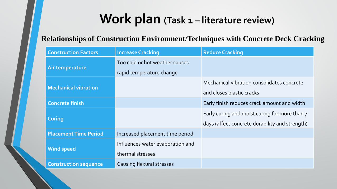
Work plan (Task 1 – literature review)
Construction Factors Increase Cracking Reduce Cracking
Air temperatureToo cold or hot weather causes
rapid temperature change
Mechanical vibrationMechanical vibration consolidates concrete
and closes plastic cracks
Concrete finish Early finish reduces crack amount and width
CuringEarly curing and moist curing for more than 7
days (affect concrete durability and strength)
Placement Time Period Increased placement time period
Wind speedInfluences water evaporation and
thermal stresses
Construction sequence Causing flexural stresses
Relationships of Construction Environment/Techniques with Concrete Deck Cracking
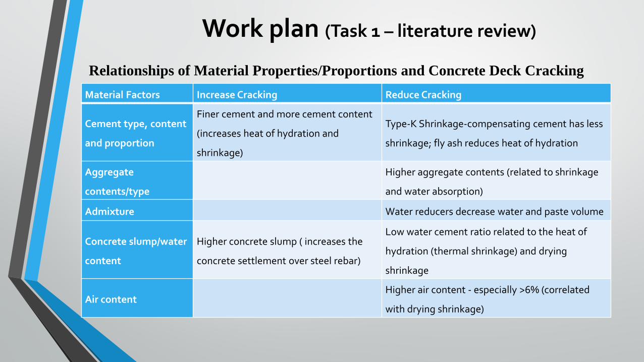
Work plan (Task 1 – literature review)
Relationships of Material Properties/Proportions and Concrete Deck CrackingMaterial Factors Increase Cracking Reduce Cracking
Cement type, content
and proportion
Finer cement and more cement content
(increases heat of hydration and
shrinkage)
Type-K Shrinkage-compensating cement has less
shrinkage; fly ash reduces heat of hydration
Aggregate
contents/type
Higher aggregate contents (related to shrinkage
and water absorption)
Admixture Water reducers decrease water and paste volume
Concrete slump/water
content
Higher concrete slump ( increases the
concrete settlement over steel rebar)
Low water cement ratio related to the heat of
hydration (thermal shrinkage) and drying
shrinkage
Air contentHigher air content - especially >6% (correlated
with drying shrinkage)
Task 2 – Step 1: Review and field visits
To understanding the degree and characteristics causing transverse deck cracking :
• Visited the 22 bridges
• Mapped their deck cracking through field trips
Reviewed inspection reports for 116 bridges constructed in the past 5 years and identified 22 bridges with transverse deck cracking
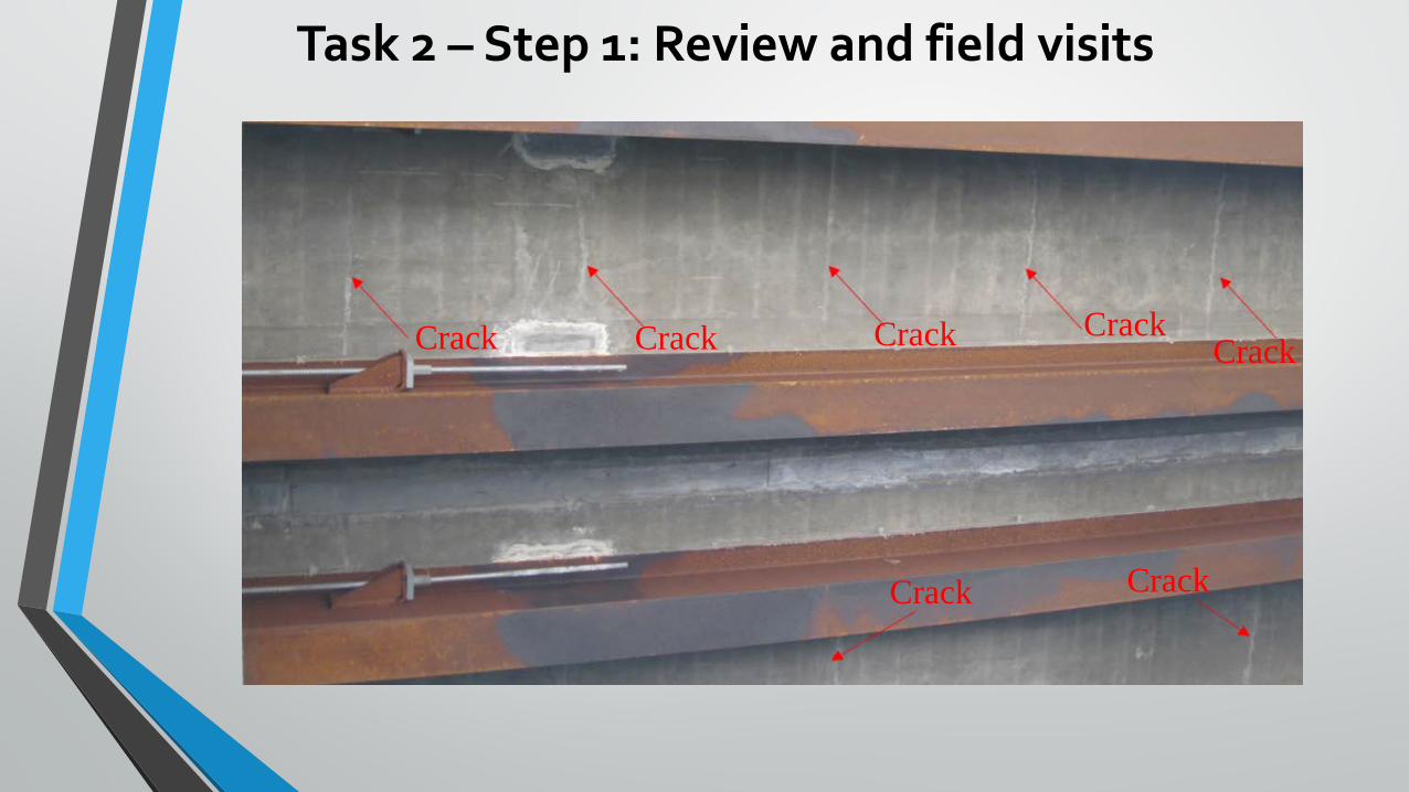
Task 2 – Step 1: Review and field visits
Crack Crack Crack Crack Crack
Crack Crack
Task 2 – Step 1: Review and field visits
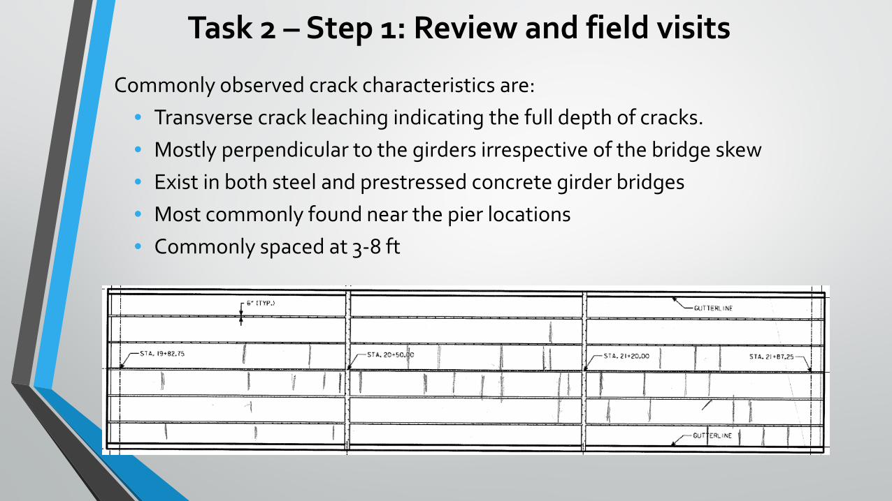
Commonly observed crack characteristics are:• Transverse crack leaching indicating the full depth of cracks.• Mostly perpendicular to the girders irrespective of the bridge skew• Exist in both steel and prestressed concrete girder bridges• Most commonly found near the pier locations• Commonly spaced at 3-8 ft
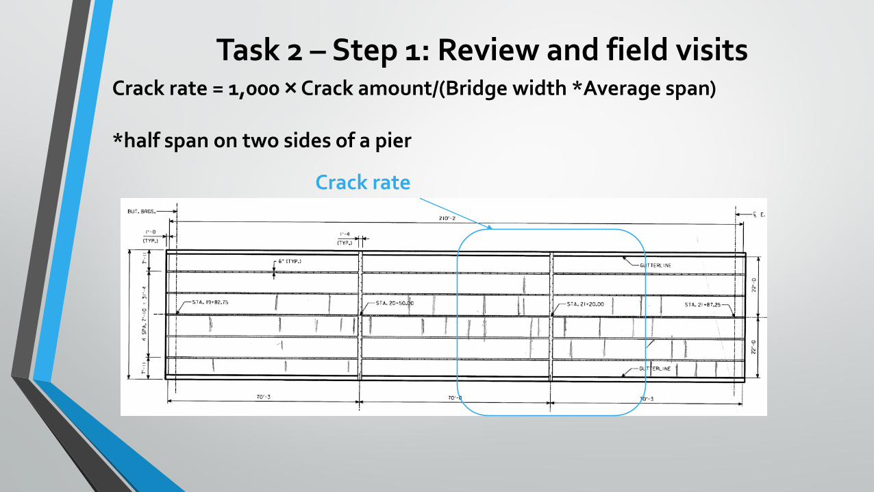
Crack rate = 1,000 × Crack amount/(Bridge width *Average span)
*half span on two sides of a pier
Crack rate
Task 2 – Step 1: Review and field visits
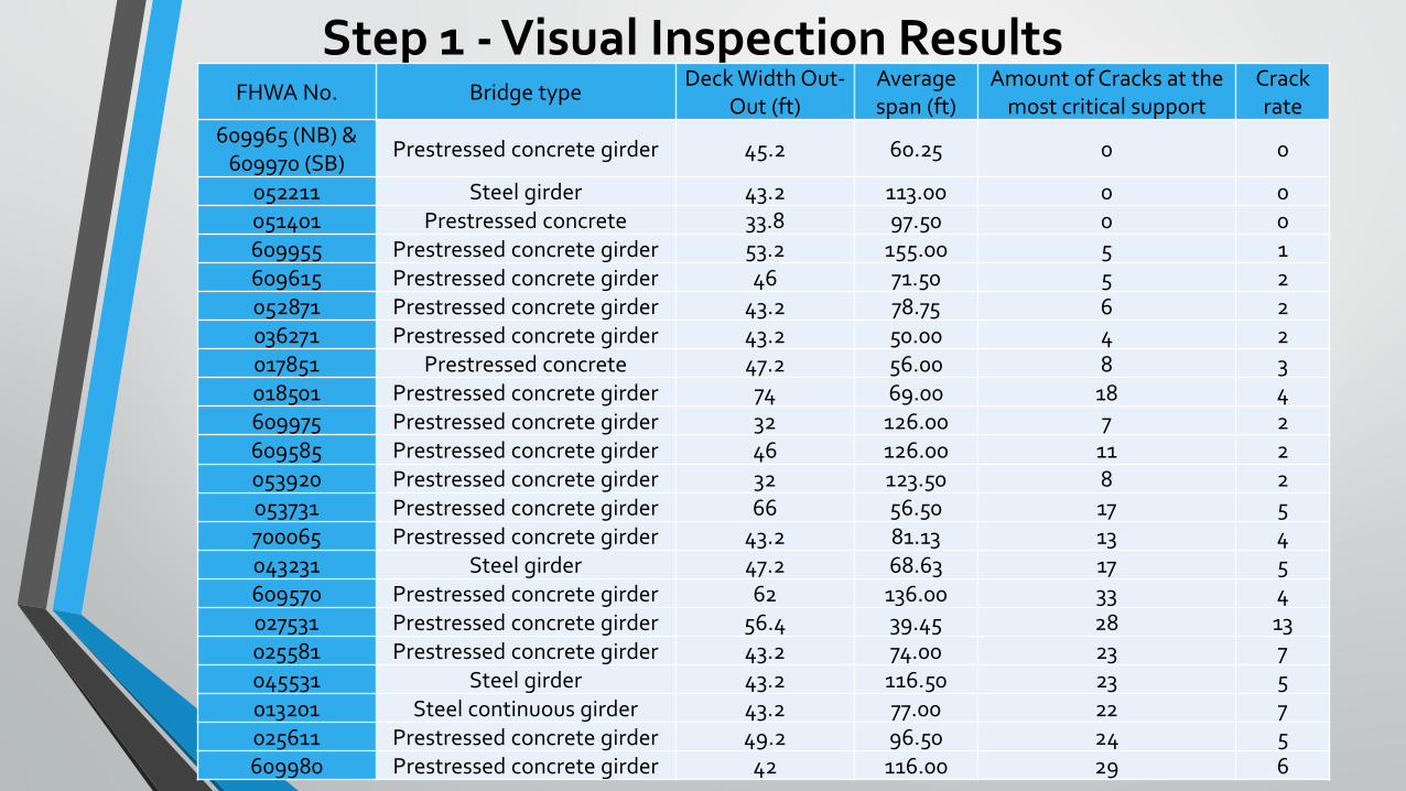
Step 1 - Visual Inspection ResultsFHWA No. Bridge type
Deck Width Out-Out (ft)
Average span (ft)
Amount of Cracks at the most critical support
Crack rate
609965 (NB) & 609970 (SB)
Prestressed concrete girder 45.2 60.25 0 0
052211 Steel girder 43.2 113.00 0 0051401 Prestressed concrete 33.8 97.50 0 0609955 Prestressed concrete girder 53.2 155.00 5 1609615 Prestressed concrete girder 46 71.50 5 2052871 Prestressed concrete girder 43.2 78.75 6 2036271 Prestressed concrete girder 43.2 50.00 4 2017851 Prestressed concrete 47.2 56.00 8 3018501 Prestressed concrete girder 74 69.00 18 4609975 Prestressed concrete girder 32 126.00 7 2609585 Prestressed concrete girder 46 126.00 11 2053920 Prestressed concrete girder 32 123.50 8 2053731 Prestressed concrete girder 66 56.50 17 5700065 Prestressed concrete girder 43.2 81.13 13 4043231 Steel girder 47.2 68.63 17 5609570 Prestressed concrete girder 62 136.00 33 4027531 Prestressed concrete girder 56.4 39.45 28 13025581 Prestressed concrete girder 43.2 74.00 23 7045531 Steel girder 43.2 116.50 23 5013201 Steel continuous girder 43.2 77.00 22 7025611 Prestressed concrete girder 49.2 96.50 24 5609980 Prestressed concrete girder 42 116.00 29 6
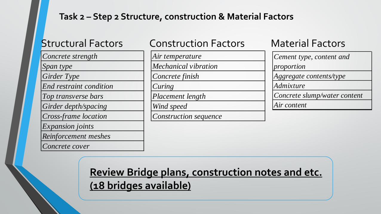
Task 2 – Step 2 Structure, construction & Material Factors
Structural Factors Construction Factors Concrete strengthSpan typeGirder TypeEnd restraint conditionTop transverse barsGirder depth/spacingCross-frame locationExpansion jointsReinforcement meshesConcrete cover
Air temperatureMechanical vibrationConcrete finishCuringPlacement lengthWind speedConstruction sequence
Cement type, content and proportionAggregate contents/typeAdmixtureConcrete slump/water contentAir content
Material Factors
Review Bridge plans, construction notes and etc. (18 bridges available)
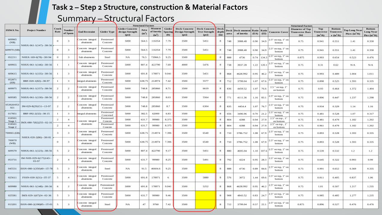
Deck area
Deck moment of inertia
Ratio (EA)
Ratio (EI) Concrete Cover
Diameter of Top Transverse Bars
(in)
Top Transverse
(in2/ft)
Bottom Transverse (in2/ft)
Top Long Near Piers (in2/ft)
Bottom Long Near Pier (in2/ft)
609965 (NB) 0 748 3988.48 0.90 34.92.5'' on top, 1'' on
bottom 0.75 0.941 0.551 1.41 0.358
609970 (SB) 0 748 3988.48 0.90 34.92.5'' on top, 1'' on
bottom 0.75 0.941 0.551 1.41 0.358
052211 NHSX-169-6(78)--3H-94
0 888 4736 0.74 134.3 2.5'' on top, 1'' on bottom
0.875 0.993 0.654 0.523 0.476
609955NHSX-061-1(146)--
3H-56 1 738 3937.28 1.22 120.12.5'' on top, 1'' on
bottom 0.75 0.31 0.62 N/A N/A
609615NHSX-061-1(135)--
3H-56 1 868 4628.992 0.95 46.22.5'' on top, 1'' on
bottom 0.75 0.993 0.489 1.004 1.011
052871 (EB) BRF-020-1(82)--38-97
1 712 3799.04 1.07 67.6 2.5'' on top, 1'' on bottom
0.75 0.898 0.525 1.593 0.335
609975NHSX-061-1(157)--
3H-56 2 836 4459.52 1.07 76.62.5 '' on top, 1''
on bottom 0.75 0.93 0.464 1.372 1.404
609585NHSX-061-1(130)--
3H-56 2 771 4111.36 1.16 83.12.5'' on top, 1'' on
bottom 0.75 0.896 0.447 1.237 1.298
053920/053921
IM-029-8(29)151--13-97 2 835 4454.4 1.07 76.7
2.5'' on top, 1'' on bottom 0.75 0.934 0.329 1.14 1.16
017851 BRF-092-2(32)--38-15
1 656 3496.96 0.70 21.2 2.5'' on top, 1'' on bottom
0.75 0.481 0.528 1.07 0.317
018501 Stage 1
2 804 4288 0.94 27.9 2.5'' on top , 1'' on bottom
0.75 0.481 0.479 1.182 1.202
018501 Stage 2
2 804 4288 0.94 27.9 2.5'' on top , 1'' on bottom
0.75 0.961 0.479 1.182 1.202
700065 (EB) 3 710 3786.752 1.08 67.92.5'' on top, 1'' on
bottom 0.75 0.893 0.528 1.593 0.335
700070 (WB) 0 710 3786.752 1.08 67.92.5'' on top, 1'' on
bottom 0.75 0.893 0.528 1.593 0.335
609570NHSX-061-1(123)--
3H-56 5 880 4695.04 1.10 107.62.5'' on top, 1'' on
bottom 0.75 0.539 0.532 1.2 1.2
053731IM-NHS-029-
6(175)143--03-97 2 792 4224 0.95 28.32.5'' on top, 1'' on
bottom 0.75 0.645 0.322 0.993 0.99
045531ISSN-080-1(350)40-
-1T-78 5 888 4736 0.89 84.62.5'' on top, 1'' on
bottom 0.75 0.991 0.652 0.369 0.335
025611FSSN-030-3(31)--
3T-37 5 576 3072 1.44 69.62.5'' on top, 1'' on
bottom 0.75 0.811 0.405 0.837 1.06
609980 NHSX-061-1(148)--3H-56
6 868 4628.992 0.95 46.2 2.5'' on top, 1'' on bottom
0.75 1.01 0.507 1.217 1.235
025581IMX-029-1(67)24--
02-36 5 908 4843.52 0.83 24.72.5'' on top, 1'' on
bottom 0.75 0.985 0.485 1.277 1.235
013201ISSN-080-2(198)85-
-1T-01 5 712 3799.04 0.57 22.12.5'' on top, 1'' on
bottom 0.875 0.896 0.527 0.476 0.476
Structural FactorsCrack RateProject Number
NHSX-061-1(147)--3H-56
IMX-080-7(82)255--02-16
NHSX-020-2(86)--3H-81
FHWA No.Number of Spans End Restraint Girder Type
Girder Concrete design Strength
(psi)
Area (in2)
Moment of Inertia
(in4)
Girder Spacing
(ft)
Deck Concrete Design Strength
(psi)
Deck Concrete Test Strength
(psi)
Deck depth
(in)
609965 (NB) 0 3
Concrete integral abutments
Prestressed Concrete 5000 564.5 116354 7.79 3500 5451 8
609970 (SB) 0 3Concrete integral
abutments Prestressed Concrete 5000 564.5 116354 7.79 3500 5451 8
052211 NHSX-169-6(78)--3H-94 0 3 Sub abutments Steel NA 76.5 73966.5 9.25 3500 8
609955 NHSX-061-1(146)--3H-56 1 1Concrete integral
abutments Prestressed Concrete 5000 807.4 422790 7.69 4000 5476 8
609615 NHSX-061-1(135)--3H-56 1 3Concrete integral
abutments Prestressed Concrete 5000 691.8 178971 9.041 3500 5451 8
052871 (EB)
BRF-020-1(82)--38-97 1 3 Integral abutments Prestressed Concrete
5000 638.75 214974 7.42 3500 5577 8
609975 NHSX-061-1(157)--3H-56 2 2Concrete integral
abutments Prestressed Concrete 5000 748.8 285860 8.71 3500 6619 8
609585 NHSX-061-1(130)--3H-56 2 2Concrete integral
abutments Prestressed Concrete 5000 748.8 285860 8.03 3500 5564 8
053920/053921 IM-029-8(29)151--13-97 2 2
Concrete integral abutments
Prestressed Concrete 5000 748.8 285860 8.7 3500 6304 8
017851 BRF-092-2(32)--38-15 1 3 Integral abutments Prestressed Concreted
5000 382.5 62000 6.83 3500 8
018501 Stage 1
2 4 Prestressed Concete
5000 631.7 99980 8.375 3500 8
018501 Stage 2
2 4 Prestressed Concete
5000 631.7 99980 8.375 3500 8
700065 (EB) 3 3Concrete integral
abutments Prestressed Concrete 5000 638.75 214974 7.396 3500 6540 8
700070 (WB) 0 3
Concrete integral abutments
Prestressed Concrete 5000 638.75 214974 7.396 3500 6540 8
609570 NHSX-061-1(123)--3H-56 5 2Concrete integral
abutments Prestressed Concrete 5000 807.4 422790 9.17 3500 5451 8
053731IM-NHS-029-6(175)143--
03-97 2 4Concrete integral
abutments Prestressed Concrete 5000 631.7 99980 8.25 3500 5491 8
045531 ISSN-080-1(350)40--1T-78 5 3Concrete integral
abutments Steel NA 91.5 46604.6 9.25 3500 8
025611 FSSN-030-3(31)--3T-37 5 4Concrete integral
abutments Prestressed Concrete 5000 691.8 178971 6 3500 5880 8
609980 NHSX-061-1(148)--3H-56 6 2 Concrete integral abutments
Pretensioned Concrete
5000 691.8 178971 9.041 3500 5252 8
025581 IMX-029-1(67)24--02-36 5 3Concrete integral
abutments Prestressed Concrete 5000 631.7 99980 9.46 3500 8
013201 ISSN-080-2(198)85--1T-01 5 3Concrete integral
abutments Steel NA 47 9760 7.42 3500 8
Structural Factors
IMX-080-7(82)255--02-16Concrete integral
abutments
NHSX-020-2(86)--3H-81
FHWA No. Project NumberCrack Rate
NHSX-061-1(147)--3H-56
Summary – Structural FactorsTask 2 – Step 2 Structure, construction & Material Factors
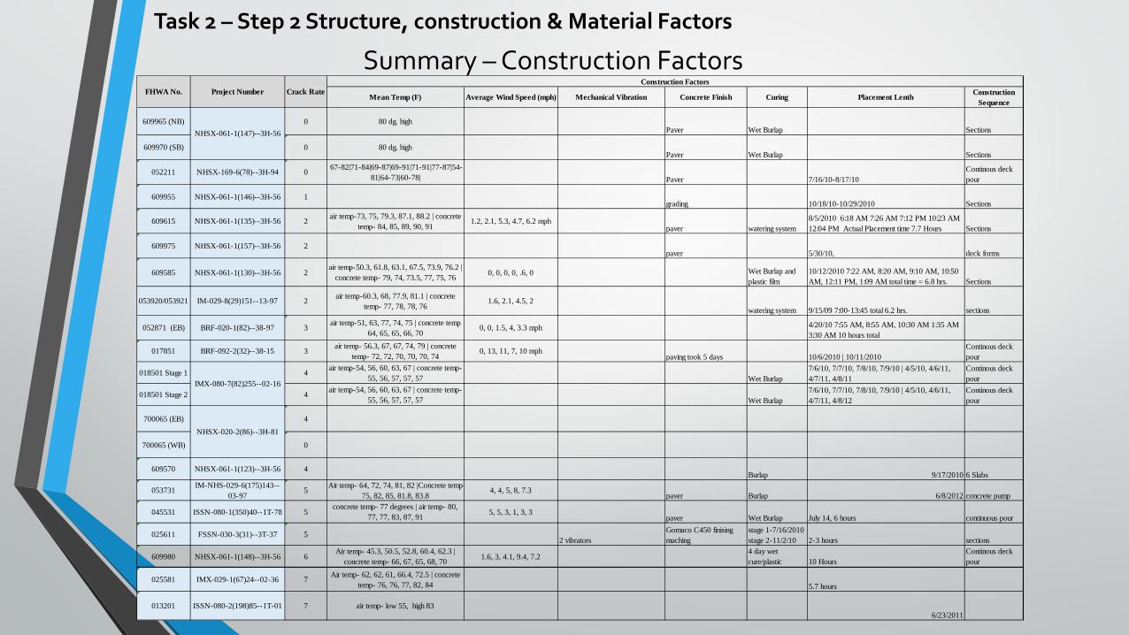
Summary – Construction FactorsTask 2 – Step 2 Structure, construction & Material Factors
Mean Temp (F) Average Wind Speed (mph) Mechanical Vibration Concrete Finish Curing Placement Lenth Construction Sequence
609965 (NB) 0 80 dg. highPaver Wet Burlap Sections
609970 (SB) 0 80 dg. highPaver Wet Burlap Sections
052211 NHSX-169-6(78)--3H-94 0 67-82|71-84|69-87|69-91|71-91|77-87|54-81|64-73|60-78| Paver 7/16/10-8/17/10
Continous deck pour
609955 NHSX-061-1(146)--3H-56 1grading 10/18/10-10/29/2010 Sections
609615 NHSX-061-1(135)--3H-56 2 air temp-73, 75, 79.3, 87.1, 88.2 | concrete temp- 84, 85, 89, 90, 91
1.2, 2.1, 5.3, 4.7, 6.2 mphpaver watering system
8/5/2010 6:18 AM 7:26 AM 7:12 PM 10:23 AM 12:04 PM Actual Placement time 7.7 Hours Sections
609975 NHSX-061-1(157)--3H-56 2paver 5/30/10, deck forms
609585 NHSX-061-1(130)--3H-56 2air temp-50.3, 61.8, 63.1, 67.5, 73.9, 76.2 |
concrete temp- 79, 74, 73.5, 77, 75, 76 0, 0, 0, 0, .6, 0 Wet Burlap and plastic film
10/12/2010 7:22 AM, 8:20 AM, 9:10 AM, 10:50 AM, 12:11 PM, 1:09 AM total time = 6.8 hrs. Sections
053920/053921 IM-029-8(29)151--13-97 2 air temp-60.3, 68, 77.9, 81.1 | concrete temp- 77, 78, 78, 76
1.6, 2.1, 4.5, 2watering system 9/15/09 7:00-13:45 total 6.2 hrs. sections
052871 (EB) BRF-020-1(82)--38-97 3 air temp-51, 63, 77, 74, 75 | concrete temp 64, 65, 65, 66, 70
0, 0, 1.5, 4, 3.3 mph 4/20/10 7:55 AM, 8:55 AM, 10:30 AM 1:35 AM 3:30 AM 10 hours total
017851 BRF-092-2(32)--38-15 3 air temp- 56.3, 67, 67, 74, 79 | concrete temp- 72, 72, 70, 70, 70, 74
0, 13, 11, 7, 10 mphpaving took 5 days 10/6/2010 | 10/11/2010
Continous deck pour
018501 Stage 1 4 air temp-54, 56, 60, 63, 67 | concrete temp- 55, 56, 57, 57, 57 Wet Burlap
7/6/10, 7/7/10, 7/8/10, 7/9/10 | 4/5/10, 4/6/11, 4/7/11, 4/8/11
Continous deck pour
018501 Stage 2 4 air temp-54, 56, 60, 63, 67 | concrete temp- 55, 56, 57, 57, 57 Wet Burlap
7/6/10, 7/7/10, 7/8/10, 7/9/10 | 4/5/10, 4/6/11, 4/7/11, 4/8/12
Continous deck pour
700065 (EB) 4
700065 (WB) 0
609570 NHSX-061-1(123)--3H-56 4Burlap 9/17/2010 6 Slabs
053731 IM-NHS-029-6(175)143--03-97
5 Air temp- 64, 72, 74, 81, 82 |Concrete temp- 75, 82, 85, 81.8, 83.8
4, 4, 5, 8, 7.3paver Burlap 6/8/2012 concrete pump
045531 ISSN-080-1(350)40--1T-78 5concrete temp- 77 degrees | air temp- 80,
77, 77, 83, 87, 91 5, 5, 3, 1, 3, 3paver Wet Burlap July 14, 6 hours continuous pour
025611 FSSN-030-3(31)--3T-37 52 vibrators
Gomaco C450 finising maching
stage 1-7/16/2010 stage 2-11/2/10 2-3 hours sections
609980 NHSX-061-1(148)--3H-56 6Air temp- 45.3, 50.5, 52.8, 60.4, 62.3 |
concrete temp- 66, 67, 65, 68, 70 1.6, 3, 4.1, 9.4, 7.24 day wet cure/plastic 10 Hours
Continous deck pour
025581 IMX-029-1(67)24--02-36 7 Air temp- 62, 62, 61, 66.4, 72.5 | concrete temp- 76, 76, 77, 82, 84 5.7 hours
013201 ISSN-080-2(198)85--1T-01 7 air temp- low 55, high 836/23/2011
FHWA No. Project NumberConstruction Factors
Crack Rate
NHSX-020-2(86)--3H-81
NHSX-061-1(147)--3H-56
IMX-080-7(82)255--02-16
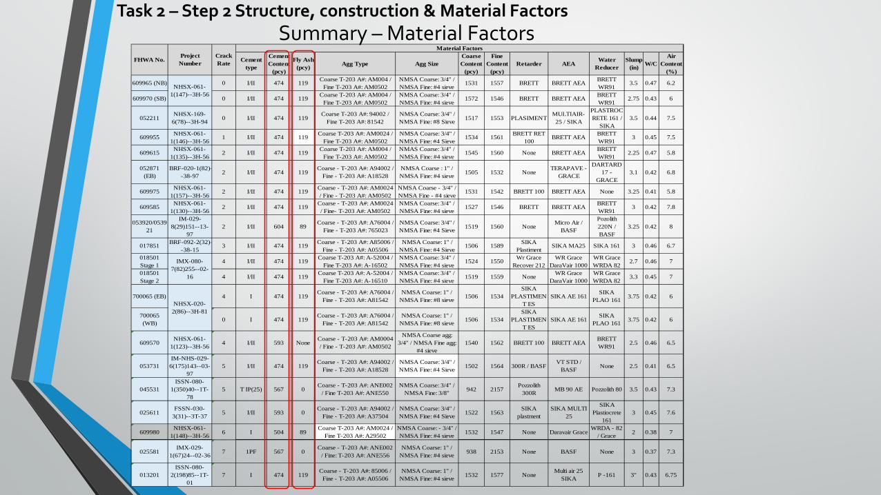
Cement type
Cement Content
(pcy)
Fly Ash (pcy) Agg Type Agg Size
Coarse Content
(pcy)
Fine Content
(pcy)Retarder AEA
Water Reducer
Slump (in) W/C
Air Content
(%)
609965 (NB) 0 I/II 474 119 Coarse T-203 A#: AM004 / Fine T-203 A#: AM0502
NMSA Coarse: 3/4'' / NMSA Fine: #4 sieve
1531 1557 BRETT BRETT AEA BRETT WR91
3.5 0.47 6.2
609970 (SB) 0 I/II 474 119 Coarse T-203 A#: AM004 / Fine T-203 A#: AM0502
NMSA Coarse: 3/4'' / NMSA Fine: #4 sieve
1572 1546 BRETT BRETT AEA BRETT WR91
2.75 0.43 6
052211NHSX-169-6(78)--3H-94 0 I/II 474 119
Coarse T-203 A#: 94002 / Fine T-203 A#: 81542
NMSA Coarse: 3/4'' / NMSA Fine: #8 Sieve 1517 1553 PLASIMENT
MULTIAIR-25 / SIKA
PLASTROCRETE 161 /
SIKA3.5 0.44 7.5
609955 NHSX-061-1(146)--3H-56
1 I/II 474 119 Coarse T-203 A#: AM0024 / Fine T-203 A#: AM0502
NMSA Coarse: 3/4'' / NMSA Fine: #4 Sieve
1534 1561 BRETT RET 100
BRETT AEA BRETT WR91
3 0.45 7.5
609615 NHSX-061-1(135)--3H-56
2 I/II 474 119 Coarse T-203 A#: AM004 / Fine T-203 A#: AM0502
NMAS Coarse: 3/4'' / NMSA Fine: #4 sieve
1545 1560 None BRETT AEA BRETT WR91
2.25 0.47 5.8
052871 (EB)
BRF-020-1(82)--38-97 2 I/II 474 119
Coarse - T-203 A#: A94002 / Fine - T-203 A#: A18528
NMSA Coarse : 1'' / NMSA Fine: #4 sieve 1505 1532 None
TERAPAVE - GRACE
DARTARD 17 -
GRACE3.1 0.42 6.8
609975 NHSX-061-1(157)--3H-56
2 I/II 474 119 Coarse - T-203 A#: AM0024 / Fine - T-203 A#: AM0502
NMSA Coarse - 3/4'' / NMSA Fine - #4 sieve
1531 1542 BRETT 100 BRETT AEA None 3.25 0.41 5.8
609585 NHSX-061-1(130)--3H-56
2 I/II 474 119 Coarse - T-203 A#: AM0024 / Fine- T-203 A#: AM0502
NMSA Coarse: 3/4'' / NMSA Fine: #4 sieve
1527 1546 BRETT BRETT AEA BRETT WR91
3 0.42 7.8
053920/053921
IM-029-8(29)151--13-
972 I/II 604 89
Coarse - T-203 A#: A76004 / Fine - T-203 A#: 765023
NMSA Coarse: 3/4" / NMSA Fine: #4 Sieve 1519 1560 None
Micro Air / BASF
Pozolith 220N / BASF
3.25 0.42 8
017851 BRF-092-2(32)--38-15
3 I/II 474 119 Coarse - T-203 A#: A85006 / Fine - T-203 A#: A05506
NMSA Coarse: 1'' / NMSA Fine: #4 Sieve
1506 1589 SIKA Plastiment
SIKA MA25 SIKA 161 3 0.46 6.7
018501 Stage 1
4 I/II 474 119 Coarse T-203 A#: A-52004 / Fine T-203 A#: A-16502
NMSA Coarse: 3/4'' / NMSA Fine: #4 sieve
1524 1550 Wr Grace Recover 212
WR Grace DaraVair 1000
WR Grace WRDA 82
2.7 0.46 7
018501 Stage 2
4 I/II 474 119 Coarse T-203 A#: A-52004 / Fine T-203 A#: A-16510
NMSA Coarse: 3/4'' / NMSA Fine: #4 sieve
1519 1559 None WR Grace DaraVair 1000
WR Grace WRDA 82
3.3 0.45 7
700065 (EB) 4 I 474 119Coarse - T-203 A#: A76004 /
Fine - T-203 A#: A81542NMSA Coarse: 1'' /
NMSA Fine: #8 sieve 1506 1534SIKA
PLASTIMENT ES
SIKA AE 161SIKA
PLAO 161 3.75 0.42 6
700065 (WB) 0 I 474 119
Coarse - T-203 A#: A76004 / Fine - T-203 A#: A81542
NMSA Coarse: 1'' / NMSA Fine: #8 sieve 1506 1534
SIKA PLASTIMEN
T ESSIKA AE 161
SIKA PLAO 161 3.75 0.42 6
609570NHSX-061-
1(123)--3H-56 4 I/II 593 NoneCoarse - T-203 A#: AM0004 / Fine - T-203 A#: AM0502
NMSA Coarse agg: 3/4'' / NMSA Fine agg:
#4 sieve1540 1562 BRETT 100 BRETT AEA
BRETT WR91 2.5 0.46 6.5
053731IM-NHS-029-
6(175)143--03-97
5 I/II 474 119Coarse - T-203 A#: A94002 /
Fine - T-203 A#: A18528NMSA Coarse: 3/4'' / NMSA Fine: #4 Sieve 1502 1564 300R / BASF
VT STD / BASF None 2.5 0.41 6.5
045531ISSN-080-
1(350)40--1T-78
5 T IP(25) 567 0Coarse - T-203 A#: ANE002
/ Fine T-203 A#: ANE550NMSA Coarse: 3/4'' /
NMSA Fine: 3/8'' 942 2157Pozzolith
300R MB 90 AE Pozzolith 80 3.5 0.43 7.3
025611FSSN-030-
3(31)--3T-37 5 I/II 593 0Coarse - T-203 A#: A94002 /
Fine - T-203 A#: A37504NMSA Coarse: 3/4'' / NMSA Fine: #4 Sieve 1522 1563
SIKA plastment
SIKA MULTI 25
SIKA Plastiocrete
1613 0.45 7.6
609980NHSX-061-
1(148)--3H-56 6 I 504 89Coarse T-203 A#: AM0024 /
Fine T-203 A#: A29502NMSA Coarse: - 3/4'' / NMSA Fine: #4 sieve 1532 1547 None Daravair Grace
WRDA - 82 / Grace 2 0.38 7
025581IMX-029-
1(67)24--02-36 7 1PF 567 0Coarse - T-203 A#: ANE002
/ Fine: T-203 A#: ANE556NMSA Coarse: 1'' /
NMSA Fine: #4 sieve 938 2153 None BASF None 3 0.37 7.3
013201ISSN-080-
2(198)85--1T-01
7 I 474 119Coarse - T-203 A#: 85006 / Fine - T-203 A#: A05506
NMSA Coarse: 1'' / NMSA Fine: #4 sieve 1532 1577 None
Multi air 25 SIKA P -161 3'' 0.43 6.75
Crack Rate
Material Factors
NHSX-020-2(86)--3H-81
FHWA No.Project Number
NHSX-061-1(147)--3H-56
IMX-080-7(82)255--02-
16
Summary – Material FactorsTask 2 – Step 2 Structure, construction & Material Factors
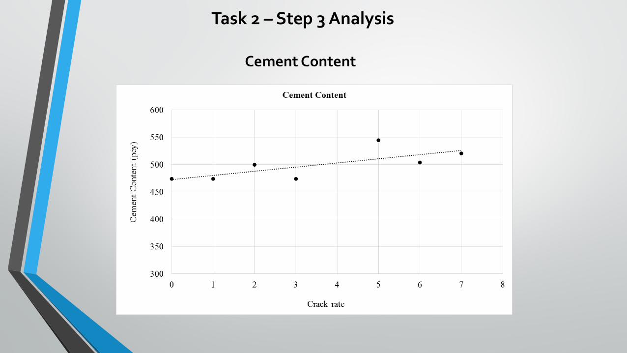
Cement Content
Task 2 – Step 3 Analysis
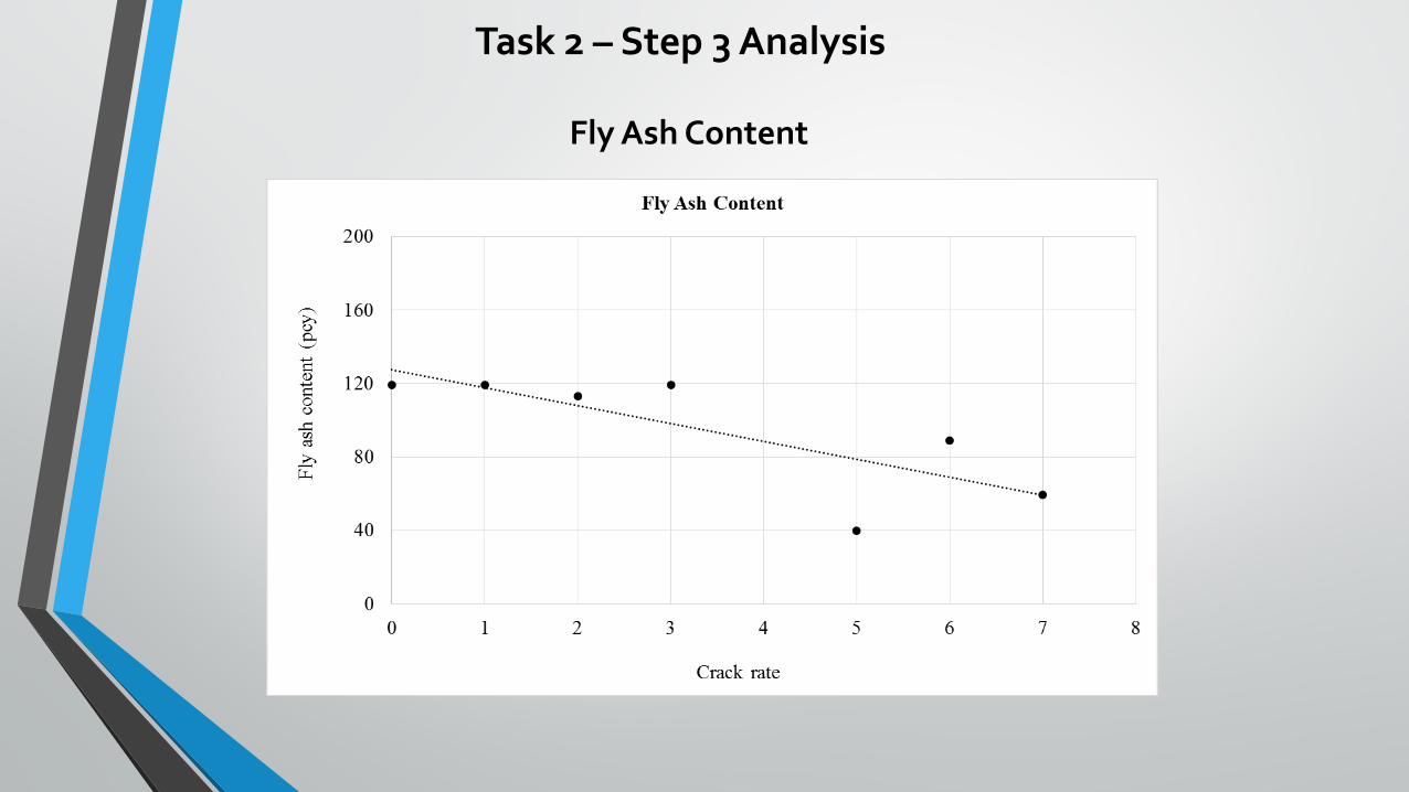
Fly Ash Content
Task 2 – Step 3 Analysis
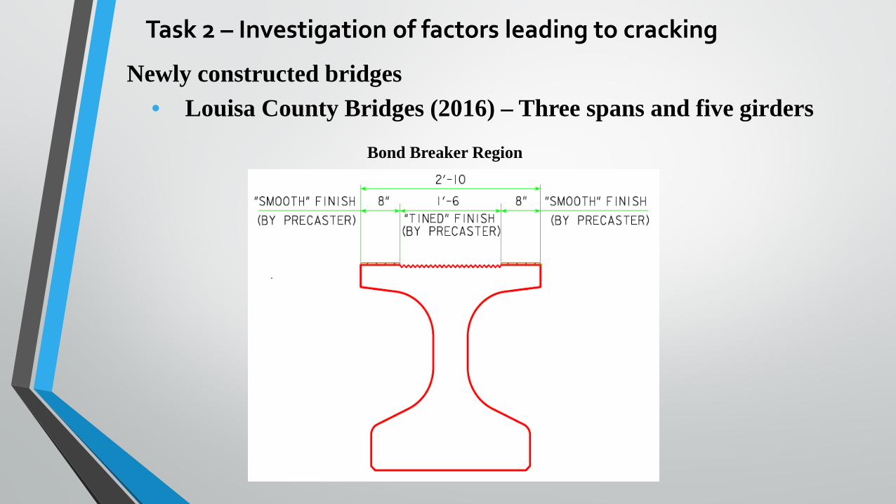
• Louisa County Bridges (2016) – Three spans and five girders
Task 2 – Investigation of factors leading to cracking
Newly constructed bridges
Bond Breaker Region
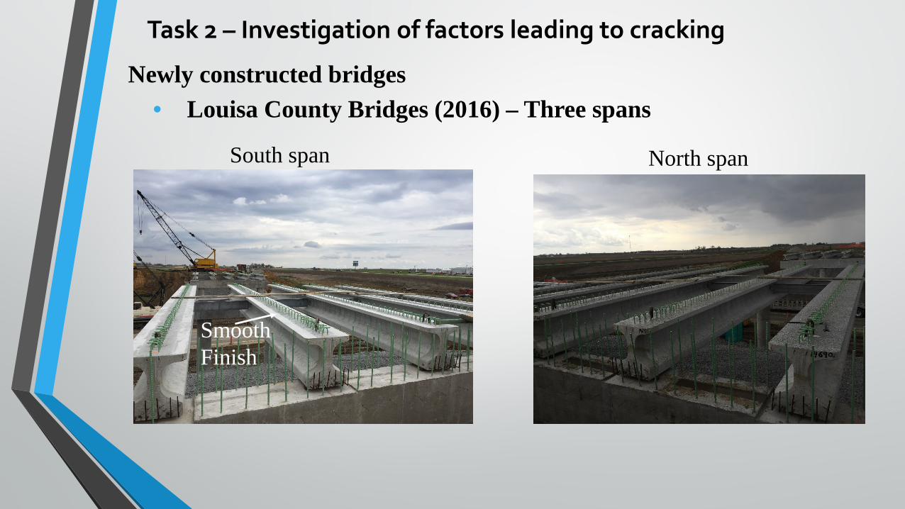
• Louisa County Bridges (2016) – Three spansNewly constructed bridges
Smooth Finish
South span North span
Task 2 – Investigation of factors leading to cracking
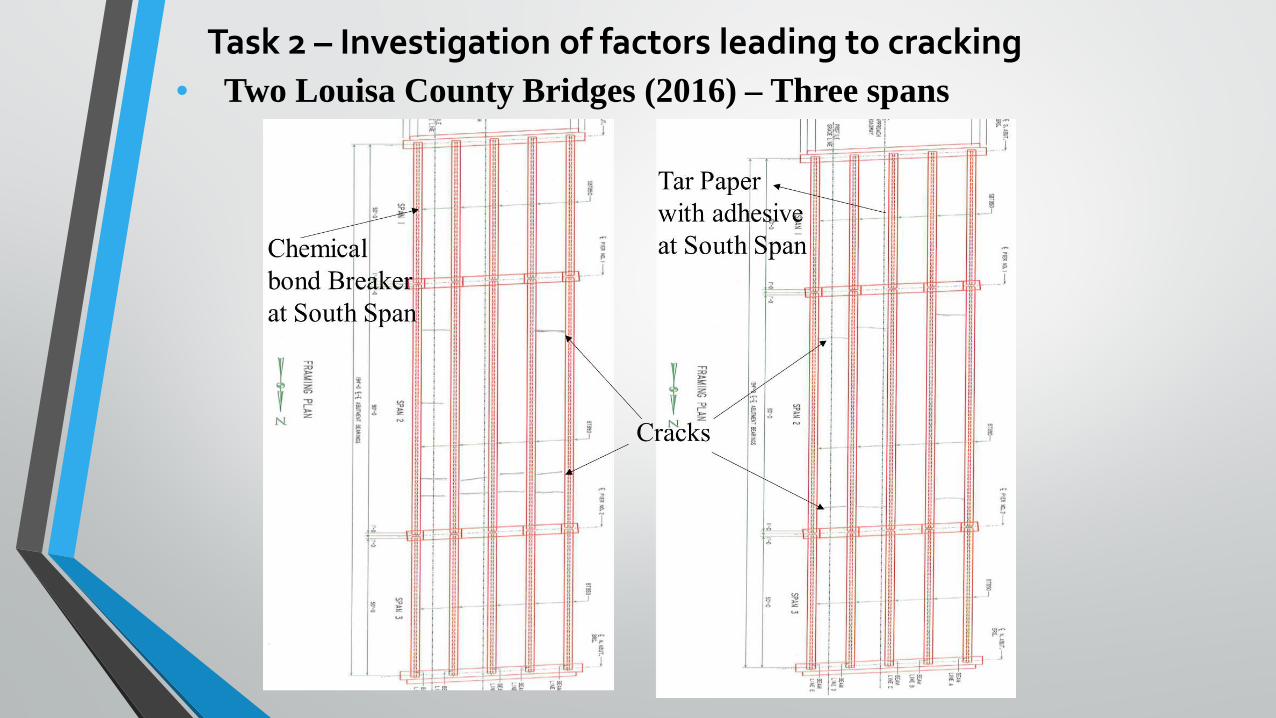
• Two Louisa County Bridges (2016) – Three spansTask 2 – Investigation of factors leading to cracking
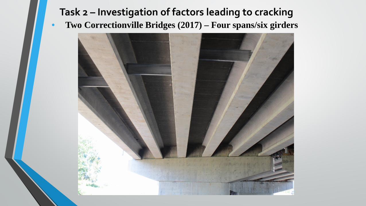
• Two Correctionville Bridges (2017) – Four spans/six girdersTask 2 – Investigation of factors leading to cracking
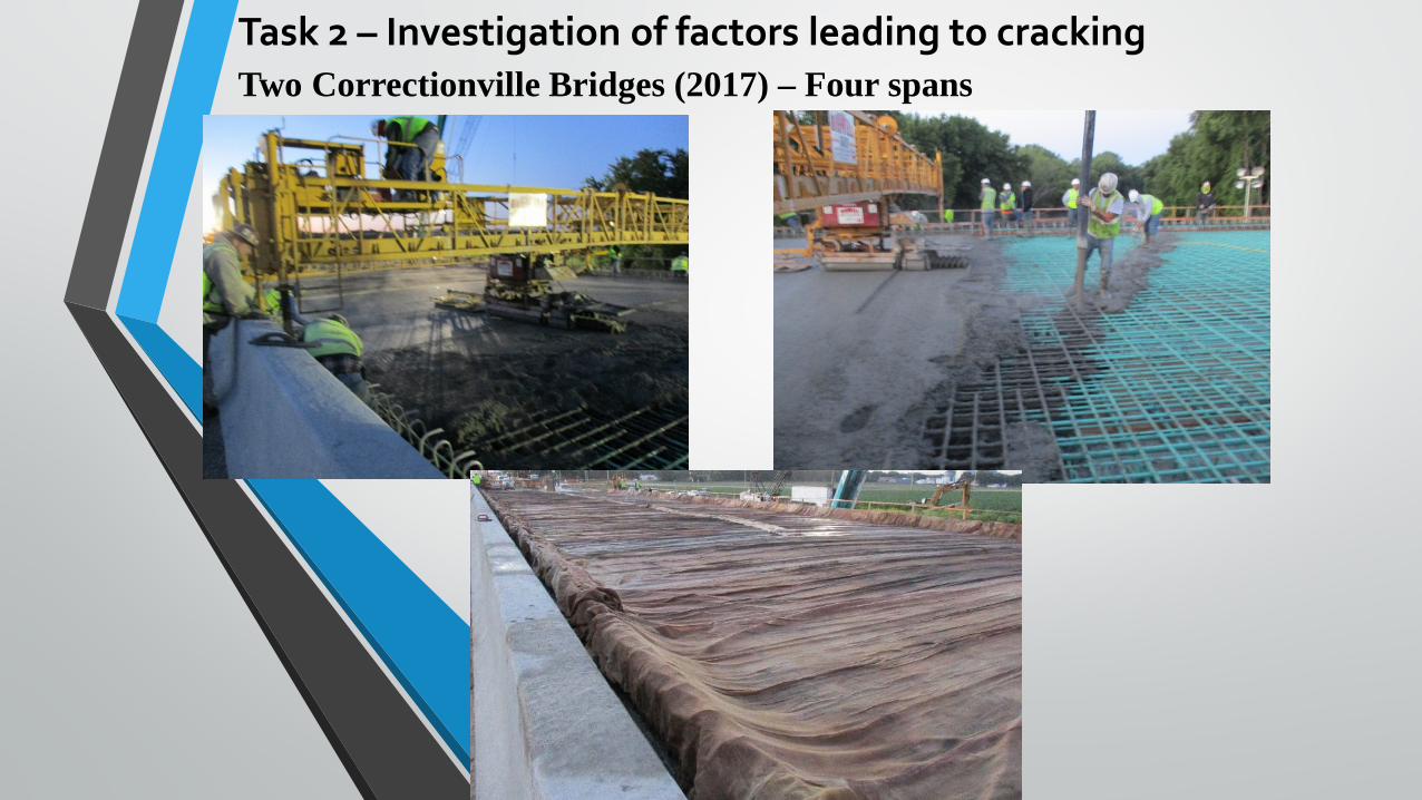
• Two Correctionville Bridges (2017) – Four spansTask 2 – Investigation of factors leading to cracking
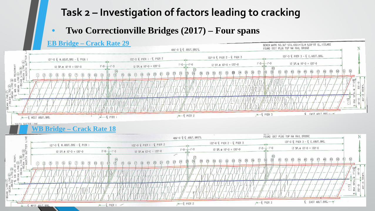
• Two Correctionville Bridges (2017) – Four spans
WB Bridge – Crack Rate 18
EB Bridge – Crack Rate 29
Task 2 – Investigation of factors leading to cracking
Summary and Conclusions
Important factors causing transverse deck cracking were reviewed and identified from the literature.
Field visits of 24 bridges were conducted and important factors for these bridges were extracted. The debonding effect between deck and girders were studied and the deck placement process was documented. The following observed crack characteristics are summarized:
• Transverse crack leaching indicates full depth cracks.• Mostly perpendicular to the girders irrespective of the bridge skew• Exist in both steel and prestressed concrete girder bridges• Most commonly found near the pier locations• Commonly spaced at 3-8 ft
More data on more bridges are being obtained for examining the correlations between the degree of transverse deck cracking and the magnitudes/characteristics of all the important factors.

Thanks For Your Attention!
Questions?