Embed Size (px)
Citation preview

Received July 3, 2018, accepted August 9, 2018, date of publication August 13, 2018, date of current version September 5, 2018.
Digital Object Identifier 10.1109/ACCESS.2018.2865137
Caterpillar RLNC With Feedback (CRLNC-FB):Reducing Delay in Selective RepeatARQ Through CodingFRANK GABRIEL 1, SIMON WUNDERLICH 1, SREEKRISHNA PANDI 1,FRANK H. P. FITZEK1, AND MARTIN REISSLEIN 2, (Fellow, IEEE)1Deutsche Telekom Chair of Communication Networks, 5G Lab Germany, Technical University Dresden, 01062 Dresden, Germany2School of Electrical, Computer, and Energy Engineering, Arizona State University, Tempe, AZ 85287-5706, USA
Corresponding author: Martin Reisslein ([email protected])
This work was supported in part by Ericsson, in part by Deutsche Telekom, and in part by the Free State of Saxony through the EuropeanCommission for the Atto3D Project.
ABSTRACT Wireless networks typically employ some form of forward error correction (FEC) coding andsome automatic repeat request (ARQ) protocol to ensure reliable data transmission over lossy channels.We propose to integrate FEC and ARQ in the context of random linear network coding (RLNC). In particular,we develop Caterpillar RLNC with feedback (CRLNC-FB), an RLNC approach with a finite sliding packettransmission window in conjunction with feedback-based selective repeat ARQ. CRLNC-FB employs anovel RLNC decoding method based on a band-form of Gaussian elimination. In response to lost packets,CRLNC-FB retransmits lost packets in systematic (uncoded) form to aid fast in-order packet delivery atthe receiver. Extensive performance evaluations indicate that CRLNC-FB gives higher throughput-delayperformance than the preceding RLNC approaches with feedback. In particular, CRLNC-FB with its slidingwindow achieves lower delays than block-based RLNC. Also, the retransmission of uncoded source packetsin CRLNC-FB contributes to a significantly higher throughput-delay performance than loss recovery throughcoded packets interspersed among future source packets at a prescribed code rate.
INDEX TERMS Automatic repeat request (ARQ) protocol, random linear network coding (RLNC), reliabledata transfer, packet delay, throughput-delay tradeoff.
I. INTRODUCTIONA. MOTIVATIONIncreasing transmission bitrates and coverage distances inmodern wireless systems lead to large bandwidth-delayproducts. On the other hand, the burst error characteris-tics of wireless systems cause losses of several successivepackets that need to be recovered for applications requir-ing reliable data transfer. Reliable data transfer is con-ventionally achieved through combinations of automaticrepeat request (ARQ) protocols and forward error correc-tion (FEC) coding. Feedback based ARQ protocols typicallyeither achieve only low throughput or incur relatively highdelays in networks with large bandwidth-delay products.FEC can mitigate delays by recovering lost packets withoutretransmissions. In particular, FEC through random linear
network coding (RLNC) has many attractive features forcomplex wireless networks [1]–[11].
The first practical RLNC approaches were basedon blocks (generations) of multiple successive sourcepackets [12], [13]. Block based RLNC incurs relatively highdelays as the encoding at the sender and the loss recovery(decoding) at the receiver operate on the basis of multiplesource packets. Recent sliding window RLNC approachesadvance the encoding window at the sender and the decodingwindow at the receiver by individual source packets and thushave the potential to reduce delays compared to block basedRLNC [14], [15]. As detailed in Section II, initial slidingwindow RLNC studies considered an infinite sliding windowthat covered all packets of a stream. The infinite sliding win-dow is impractical as it becomes computationally prohibitive.
VOLUME 6, 20182169-3536 2018 IEEE. Translations and content mining are permitted for academic research only.
Personal use is also permitted, but republication/redistribution requires IEEE permission.See http://www.ieee.org/publications_standards/publications/rights/index.html for more information.
44787

F. Gabriel et al.: CRLNC-FB: Reducing Delay in Selective Repeat ARQ Through Coding
Practical finite sliding window RLNC has received relativelylittle research attention so far, and we are aware of only oneprior approach, namely Tetrys [16]–[19], that examined finitesliding window RLNC with feedback in the context of bursterror wireless networks.
B. CONTRIBUTIONWe develop and evaluate a novel sliding windowRLNC approach that exploits feedback based ARQ toovercome bursty packet losses. In particular, we introduceCaterpillar RLNCwith Feedback (CRLNC-FB). CRLNC-FBcombines RLNC over a finite sliding window with feed-back based retransmission of lost source packets to quicklyrecover from bursts of lost packets. CRLNC-FB employsa novel form of RLNC decoding with a band-form matrixGaussian elimination. CRLNC-FB quickly recovers fromloss bursts through retransmissions of lost source packets inuncoded (systematic) form.We conduct extensive evaluationsof CRLNC-FB for burst-error wireless channels with largebandwidth-delay products.We find that CRLNC-FB providesfavorable throughput-delay performance for a wide range ofchannel conditions and can be flexibly tuned to emphasizelow delay or high throughput by setting the RLNC code rate.
II. BACKGROUND AND RELATED WORKA. RLNC OVERVIEWRLNC creates coded packets by linearly combining payloadsource packets (also referred to as source symbols) over aGalois field GF(2q). Block based RLNC operates on non-overlapping sets of W , W ≥ 1, successive source symbols.That is, the encoding window encompasses W successivesource symbols and advances in steps of W source sym-bols. The systematic variant of block based RLNC sendsthe W source symbols of a block in uncoded form, i.e.,systematically [20], followed byW (1/R− 1) coded packets,whereby R, R ≤ 1, denotes the code rate, i.e., the ratio of thenumber of source packets to the total number of transmittedpackets (systematic + coded packets).In contrast, sliding window RLNC advances the encoding
window in steps of individual source symbols [14], [21]–[24].Sliding window RLNC with systematic source symbol trans-mission enforces a prescribed code rate R by sendingS = R/(1−R) successive systematic source packets followedby one coded packet. Feedback free RLNC has been studiedin several contexts, see e.g., [25]–[31].
B. FEEDBACK BASED AUTOMATIC REPEATREQUEST (ARQ)A classic ARQ scheme is the stop-and-wait ARQ pro-tocol, also referred to as send-and-wait protocol, whichwas originally employed in IEEE 802.11 W-LANs [32].The sender sends a single packet and then stops to waitfor a feedback acknowledgement from the receiver. Thereceiver sends a feedback upon every received packet. Thesender only transmits another packet after receiving an
acknowledgement for the previous packet or after a timeout.Stop-and-wait ARQ is simple and performs very well if thepropagation delay between sender and receiver is negligiblecompared to the packet transmission time. However, increas-ing wireless network coverage distances increase the propa-gation time and improvements in modulation (e.g., OFDMAand MIMO) decrease the packet transmission time, increas-ing the bandwidth-delay product of wireless networks.Stop-and-wait ARQ achieves only low utilization, i.e., lowthroughput, in networks with a large bandwidth-delayproduct.
Modern wireless protocols therefore implement windowbased ARQ schemes. They allow a window of W , W ≥ 1,packets to be sent without waiting after each transmission.With the selective repeat form of window based ARQ,the receiver acknowledges individual received pack-ets or selectively requests retransmissions of lost packets.Selective repeat ARQ can achieve high utilization, i.e., highthroughput, if the transmission time of theW packets is largerthan the round-trip (propagation delay) time (RTT). Selectiverepeat ARQ is implemented in IEEE 802.11 W-LANs sincethe 802.11n amendment [32] as well as many cellular net-works, such as WCDMA (also known as UMTS) [33].
In order to further enhance the wireless network reliabil-ity, some wireless networks combine FEC and ARQ. Forinstance, Long Term Evolution (LTE) cellular networks use acombination of selective repeat ARQ on an upper layer and alower layer Hybrid ARQ scheme (H-ARQ) [34]–[36]. HybridARQ schemes specifically address bit errors in receivedpackets by resending (partial) packet data using FEC codes.In contrast, we consider erasure channels, where completepackets either arrive without bit errors or complete packetsare dropped. Also, hybrid ARQ schemes typically do notcombine multiple packets as we do through network codingin CRLNC-FB-FB.
C. FEEDBACK ENHANCED RLNCThe enhancement of network coding with feedback has beenconsidered in relatively few studies to date [37]. The gen-eral feedback structure for supporting RLNC has been stud-ied in [38]. General principles for enhancing multicast andbroadcast network coded transmissions with feedback havebeen examined in [39]–[48]. Block based RLNC has beenenhanced with feedback in [49] to trigger the transmission ofadditional coded packets for a generation in order to recoverfrom packet losses.
Sliding window RLNC studies have commonly exploitedreceiver feedback to advance the lower end of the encodingwindow, which covers the oldest source packets [50]–[56].Thus, these studies essentially utilize the feedback to turninfinite sliding window RLNC [14], [21]–[24], which con-siders the complete set of source symbols since the begin-ning of a stream, into finite sliding window RLNC thatconsiders a subset of the stream’s source symbols. Priorfinite sliding window RLNC studies have mainly focusedon the interactions with the Transmission Control
44788 VOLUME 6, 2018

F. Gabriel et al.: CRLNC-FB: Reducing Delay in Selective Repeat ARQ Through Coding
Protocol (TCP) [50], [51], [55], on maximizing the through-put [52], or on information theoretic characterizations [53],[54], [56]. In [57] the feedback is exploited to control thetransmission rate at the sender in order to avoid overwhelm-ing the channel.
More closely related to our study emphasis on delayreduction, the Tetrys protocol [16]–[19] exploits feedback toreduce delay for reliable data transfer by selectively removingsource symbols that have been ‘‘seen’’ at the receiver fromthe encoding window at the sender (whereby the definition of‘‘seen’’ follows from [54], [56]). Importantly, the sliding win-dow approaches that advance the lower end of the encodingwindow based on feedback cover a set of consecutive sourcesymbols within the encoding window; in contrast, the Tetrysencoding window covers only the ‘‘unseen’’ source symbols,which may be non-consecutive. However, Tetrys does notretransmit lost packets or transmit additional coded packets inresponse to losses. Instead, Tetrys continues sending new sys-tematic source symbols and coded packets at the prescribedcode rate R, whereby the coded packets are linear combi-nations of only the ‘‘unseen’’ packets. In contrast to Tetrys,our proposed CRLNC-FB retransmits lost systematic sourcepackets that cannot be recovered from the coded packets soas to actively address bursts of lost packets.
The recent analysis in [58] has modeled the decision prob-lem of sending a systematic source packet or a coded packetfor a packet erasure channel with independent packet lossesin each slot with a fixed loss probability and with a losslessfeedback channel. In contrast, we consider a more realisticburst error channel where successive slots are correlated andfeedback may be lost.
D. BANDWIDTH-DELAY CHARACTERISTICSIN WIRELESS SYSTEMSARQ protocols in modern wireless systems have to accom-modate increasing bandwidth-delay products mainly dueto increased transmission bitrates. While early 802.11bWiFi could work well with stop-and-wait ARQ due tolow transmission bitrates and short propagation distancesbetween stations, today’s cellular and satellite systems havelarge bandwidth-delay products. RLNC is generally wellsuited as a basis for reliable data transfer protocols in thesechallenging wireless communication settings [59]–[64].
LTE network measurements in 2012 [65] found approx-imately 5 ms one-way downlink delay and 15 ms one-wayuplink delay on the radio access layer, which incorporatesselective repeat ARQ and hybrid ARQ [66]. These delayvalues are also seen at the 5th percentile; thus, these delayvalues are reasonable approximations for the ‘‘good’’ caseswhere the ARQ does not add latency. These measurementswere conducted at a distance of 130 m from the base station,corresponding to a negligible propagation delay of less thana microsecond. 5G cellular networks will likely have similarcharacteristics. Considering the 1 Gbit/s user peak transmis-sion bitrate for high mobility [67], a 1 ms RTT according tothe tactile Internet delay target [68], and a 1500 byte MTU,
the round-trip bandwidth delay product is about90 packets.
Broadband communication satellites operate in differentorbits. The popular Inmarsat satellite fleet is positioned inthe geostationary equatorial orbit (GEO) of 35,786 km abovethe Earth’s equator. The one way latency is mostly governedby the speed of light propagation delay, which contributes atleast 120 ms delay. Inmarsat typically provides a maximumthroughput of 25 Mbit/s to end users. Thus, there can be upto 262 packets in flight in a direction at a time.
OneWeb [69] and SpaceX [70] plan to deploy lowearth orbit (LEO) satellite constellations [71] at an altitudeof 1,200 km, resulting in RTTs of approximately 8 ms. Otherdelay components will likely contribute larger delays, butwe consider the propagation delays as lower delay bounds.SpaceX advertises up to 1 Gbps per user, and 17–23 Gbpsper satellite. OneWeb targets 6 Gbps per satellite. Conserva-tively considering 300 Mbps results in a lower bound for thebandwidth-delay product around 210 packets.
III. CATERPILLAR RLNC WITH FEEDBACK (CRLNC-FB)PROTOCOLThis section introduces the CRLNC-FB protocol. First,the encoder operation and packet format are introduced,followed by the operation of the decoder and the feedbackformat. The main notations are summarized in Table 1.
TABLE 1. Summary of main notations.
A. ENCODING AND PACKET FORMATThe CRLNC-FB protocol employs the CRLNC encodingmechanism and extends the CRLNC packet format to supportthe decoding with feedback. We briefly review the CRLNCencoding and packet format [30] and describe the modifica-tions due to the operation with feedback. CRLNC encodingfollows the general principles of systematic RLNC with afinite sliding window coveringW successive source symbols.In particular, S, 1 ≤ S ≤ W , successive source symbols aresent uncoded (systematically), followed by one coded packetso as to achieve a code rate of R = S/(S + 1). (CRLNC-FBwithR = 1 corresponds to conventional selective repeat ARQwithout network coding.) Each source symbol is sent onlyonce, unless a retransmission is requested through feedback.A coded packet is constructed with RLNC considering all
VOLUME 6, 2018 44789

F. Gabriel et al.: CRLNC-FB: Reducing Delay in Selective Repeat ARQ Through Coding
unacknowledged source symbols within the window. Follow-ing the principles of conventional window based reliable datatransfer protocols, the encoder can send at most W sourcesymbols. Suppose that sbe denotes the highest sequence num-ber up to which all source symbols have been acknowledged,i.e., the receiver has acknowledged all preceding source sym-bols up to and including the source symbol with sequencenumber sbe to the encoder. Then, we refer to the contiguousrange of source symbol sequence numbers from sbe + 1 tosbe + W as the encoding window. The removal of the oldestsource symbol (with lowest sequence number sbe) from thewindow is commonly referred to as closing the window onsource symbol sbe .
The CRLNC packet format consisting of source packetsequence number (source symbol sequence number se forsystematic source packet; highest considered source symbolsequence number se for coded packet), the coding coeffi-cients, and the payload (systematic source packet; or codedpacket) [30] is augmented by a packet count pe. The packetcount pe is incremented for each sent packet, i.e., for eachsent systematic source packet and for each sent coded packet.This packet count is considered when interpreting the feed-back, see Section III-C. Following the principles of window-based network transport protocols [72]–[74], the packet countneeds to uniquely identify the packet transmissions. For eachsource packet se in the encoding window, the encoder mem-orizes the corresponding packet count pe(se) of the packettransmission that contained source packet se. For instance,in the example in Fig. 1, the source symbol se = 7is contained in the packet transmission with packet countpe(se = 7) = 10.
FIGURE 1. Example of a packet stream with sliding window networkcoding with window size W = 8 and code rate R = 2/3, i.e., a codedpacket after every S = 2 systematic source packets.
B. DECODING1) PRINCIPLES FOR RLNC DECODING WITH FEEDBACKThe CRLNC-FB decoder performs a novel variant of Gaus-sian elimination to recover the original source symbols fromthe coded symbols. Additionally, the decoder sends feedback
to the encoder. The feedback indicates the missing pack-ets at the decoder to give the encoder an opportunityto retransmit them. Before introducing the details of theCRLNC-FB decoding, we briefly discuss basic considera-tions for sliding window RLNC decoding in networks withfeedback.
a: DECODING WINDOW AND DECODING MATRIXAs in conventional finite sliding windowRLNC [12], [75], [76], the decoder maintains a decod-ing matrix with W rows corresponding to W successivesource symbols and W columns corresponding to the cod-ing coefficients related to the source symbols. We refer tothe range of source symbol sequence numbers covered bythe rows of the decoding matrix as the decoding window.The decoding window at the receiver is advanced by thearrival of a packet with a higher source symbol sequencenumber se than the current highest source symbol sequencenumber sd at the decoder. Specifically, upon the arrival of apacket with source symbol sequence number se > sd , thedecoding window is advanced to cover the source symbolsequence numbers se − (W − 1), . . . , se − 1, se, moreoversd is updated to se, and the decoding window is closed onany source symbols with sequence numbers se − W andlower.
b: SYSTEMATIC (UNCODED) SOURCE SYMBOLS TOSUPPORT LOW DELAYFor low-latency communication, we want to move theencoding window forward, i.e., slide the encoding windowup to the next source symbols as early as possible. Forthis reason, we adopted systematic RLNC for CRLNC-FB,i.e., we send source symbols in their original form (uncoded)and additionally send coded packets to aid recovery. Withsystematic RLNC, the decoder (receiver) can immediatelypass a received uncoded source symbol to the next higherprotocol layer, if all preceding symbols have been decoded(i.e., the in-order source symbol delivery is ensured). Thus,the decoder does not need to wait until the decodingmatrix reaches full rank, if the preceding source sym-bols have been decoded [77]–[81]. However, a lost sym-bol (in conjunction with the considered in-order deliveryrequirement) forces the decoder to wait until enough codedpackets have arrived to recover all losses, or the symbolis considered permanently lost. A symbol is consideredpermanently lost when a timeout occurs, as detailed inSection III-B.1.d, e.g., when the encoder has reached theretransmission limit and moved on to a higher sequencenumber, thus evicting an old symbol from the decodingwindow.
The CRLNC-FB decoder reduces the wait times andoccurrences of permanent losses by explicitly requesting theretransmission of lost packets (that cannot be recovered fromthe coded packets). The CRLNC-FB encoder retransmitsrequested systematic packets, while maintaining the RLNCcode rate for the retransmissions.
44790 VOLUME 6, 2018

F. Gabriel et al.: CRLNC-FB: Reducing Delay in Selective Repeat ARQ Through Coding
FIGURE 2. Illustration of three different forms of Gaussian elimination for the example stream in 1. The novel band matrix RLNC decoding performsright-to-left pivot selection and left-to-right elimination so that at most one row is removed when closing decoding window by one symbol. (a) ForwardGaussian elim. (b) Reverse Gaussian elim. (c) Band Matrix.
c: DEFINITIONS OF SOURCE SYMBOL TYPES FOR RLNCDECODINGGenerally, in block (generation) based RLNC, the decoderrecovers all symbols in a coded block when the decodingmatrix achieves full rank. In RLNC protocols it thereforesuffices to feed back the number of missing rows, withoutexplicitly identifying the missing rows [49]. However, thereare still good reasons to explicitly identify the missing rowsin the feedback. More specifically, inspired by [54] and [56],we define two main types of source symbols at the decoder.A source symbol se has been ‘‘seen’’ at the decoder if thedecoder has a pivot (i.e., a value of one) in the position forsource symbol se in the decoding matrix. In particular, eitherthe systematic source symbol se has been received at thedecoder or the systematic source symbol se was dropped bythe channel and successive coded packets were received andenabled the decoder to normalize the pivot of the decodingmatrix row corresponding to source symbol se. In the examplein Fig. 2(a), source symbols se = 1, 2, 3, 6, 7, and 8 havebeen seen.
We further define the complement of the seen sourcesymbols as the ‘‘unseen’’ source symbols. The decoderdoes not have any entries for the unseen source symbols inthe decoding matrix and requests the retransmission of theunseen source symbols in the feedback to the encoder. Inthe example in Fig. 2(a), source symbols se = 4 and 5 areunseen. Indicating the requested unseen source symbols inthe feedback in turn allows the encoder to close the encodingwindow on the source symbols that have been seen at thedecoder.
d: TIMEOUTTimeout mechanisms can be employed in CRLNC-FB tomainly reduce delays at the expense of occasional permanentsource symbol losses, i.e., by giving up on the delivery ofa source symbol. A timeout can be implemented through aretransmission limit at the encoder through specifying themaximum allowed integer number of retransmissions. If theretransmission limit has been exhausted for a source symbolse, then the encoder closes the encodingwindow on the sourcesymbol se, i.e., shifts up the encoding window to cover sourcesymbols se + 1 to se + W , allowing the transmission of anew source symbol se + W (which previously was outsidethe window). The arrival of the new source symbol se + Wwill advance the decodingwindow (decodingmatrix) to coversource symbols se+1 to se+W and any coefficients related tosource symbol se will be removed from the decoding matrix.Alternatively, a timeout could be implemented at the
decoder. Specifically, the decoder can close the decodingwin-dow on source symbols that have exceeded a prescribed delaylimit so as to meet latency requirements of the application.Upon such a timeout, the decoder sends a feedback messageindicating that the affected source symbols have been seen(essentially pretending that they have arrived) so that theencoder can advance its window.
Moreover, following the principles of the transmissioncontrol protocol (TCP) [82], the encoder maintains a timerfor the oldest unacknowledged source symbol in the win-dow. This timeout addresses scenarios with long loss burstson the encoder-to-decoder channel and/or the decoder-to-encoder channel, where the encoder may transmit many
VOLUME 6, 2018 44791

F. Gabriel et al.: CRLNC-FB: Reducing Delay in Selective Repeat ARQ Through Coding
packets and not receive any feedback packets. Without thereceipt of feedback packets, the encoder may be blocked fromfurther transmissions. This encoder blocking occurs if thewindow is full, but the oldest symbol is not acknowledged.To prevent encoder blocking, the CRLNC-FB encoder waitsfor feedback for the oldest unacknowledged source sym-bol for a prescribed timeout duration. The timeout durationmay be set similar to the timeouts in reliable data transferprotocols [83], [84]. If this timeout expires, the encoder sendsan additional coded packet that combines all presently unac-knowledged packets.
2) BAND-FORM GAUSSIAN ELIMINATIONThis section introduces a novel variant of the Gaussianelimination for RLNC decoding, namely band-form Gaus-sian elimination. Band-form Gaussian elimination facilitatesthe timely recovery of the source symbols with the aid offeedback.
Fig. 1 shows an example of a packet stream while Fig. 2(a)illustrates the corresponding decoding matrix. In the illus-trated example, a packet stream with an encoding windowof W = 8 and S = 2 systematic source symbols betweensuccessive coded packets, i.e., code rate R = 2/3, has beenongoing for a while without losses. We focus now on theexcerpt indicated by packet count values pe = 1, 2, . . . , 12(on the y-axis) and the corresponding source symbolsse = 1, 2, . . . , 8 (indicated by the x-axis position). In theexample, the packets with packet counts pe = 2, 3, . . . , 7 arelost during network transport.
a: FORWARD GAUSSIAN ELIMINATIONThe conventional forward Gaussian elimination for a matrixwith incomplete rank results in a matrix in reduced rowechelon form, as shown in Fig. 2(a), covering source symbolsse = 1, 2, . . . , 8. The conventional Gaussian eliminationproceeds in a ‘‘forward’’ manner from the top left towardsthe bottom right when forming the reduced row echelonform. With this forward Gaussian elimination, the decodermust wait with decoding source symbol se = 2 until thematrix reaches full rank and can be fully decoded. In par-ticular, the feedback acknowledges all seen source symbols,i.e., source symbols se = 1, 2, 3, 6, 7, and 8, as illustratedby the feedback message in the middle part of Fig. 2(a).More specifically, in the depicted example in Fig. 1, sourcesymbols se = 2, 3, 4, and 5 were lost. However, the tworeceived coded packets pe = 9 and 12 included all these lostsource symbols. These two coded packets are entered into thedecoding matrix using Gaussian elimination, see Fig. 2(a).In particular, the coding coefficients of the already decodedsource symbols se = 1, 6, 7, and 8 are eliminated. Then,conventional forward Gaussian elimination will normalizethe remaining left-most coefficients. The elimination pro-cess first normalizes the left-most coefficient correspondingto the pivot for source packet se = 2, and then the left-most coefficient corresponding to the pivot for source packetse = 3.
As illustrated in the decoding matrix in Fig. 2(a), sourcesymbols se = 2 and 3 have thus been ‘‘seen’’, but cannotbe decoded yet since their packets contains data from othersource symbols. That is, there are still non-zero (non-yet-eliminated) coding coefficients related to other source sym-bols in rows 2 and 3 of the decoding matrix. Source symbolsse = 4 and 5 are unseen at the decoder and the decoderthus requests their retransmission. Note that source symbolsse = 4 and 5 are contained in the received coded packetspe = 9 and 12. However, these two coded packets have been‘‘used up’’, to obtain the rows with pivots for source symbolsse = 2 and 3.Thus, the feedback message requests the retransmission
of source symbols se = 4 and 5. (For forward Gaus-sian elimination, the feedback message also needs to indi-cate the highest source symbol sequence number sed up towhich all source symbols have been decoded without anygaps, whereby sed = 1 in the example in Fig. 2(a). Uponreceipt of the feedback at the encoder, the encoding windowcan be closed on this source symbol sed and any precedingsource symbols.) Once these source symbols se = 4 and 5have been received, the matrix reaches full rank and sourcesymbols se = 2 and 3 can be decoded (recovered) anddelivered along with source symbols 4–8 to the higher layers.Alternatively, the matrix reaches full rank if the decoderreceives one of these retransmitted systematic source symbolsand the coded packet that is sent along with the retransmittedsource symbols, adhering to the prescribed code rate.
b: REVERSE GAUSSIAN ELIMINATIONAn alternative Gaussian elimination strategy is to proceed ina ‘‘reverse’’ manner from the bottom right towards the topleft with forming the reduced row echelon form, as illus-trated in Fig. 2(b). By selecting the pivots in the reversemanner, i.e., starting from the right side of the matrix, theselection of the seen packets changes slightly, as illustratedin Fig. 2(b).
However, decoding with this backward Gaussian elimi-nation is problematic for CRLNC-FB in case of a timeout(Section III-B.1.d). When the retransmission fails after thespecified timeout, then the sliding windowwill be closed, andthe symbol whose retransmission failed is removed from thewindow. This symbol removal results in a permanent symbolloss, if the symbol has not been decoded prior to the removal.Moreover, all rows in the decoding matrix with a nonzerocoefficient for this symbol are removed.
For example, for the forward Gaussian eliminationin Fig. 2(a), closing the decoding window by one sym-bol will only remove the one corresponding row from thematrix. For instance, closing the decoding window on sourcesymbol 2 in Fig. 2(a) would only remove row 2 from thedecoding matrix. In contrast, for the backward Gaussianelimination in Fig. 2(b), multiple rows need to be removedif the symbol for the second column of the decoding matrixis removed. In particular, closing the receiver window onsource symbol 2 in Fig. 2(b) implies the removal of all rows
44792 VOLUME 6, 2018

F. Gabriel et al.: CRLNC-FB: Reducing Delay in Selective Repeat ARQ Through Coding
that have a nonzero coefficient in column 2; thus, the rowscorresponding to source symbols 4 and 5 would need to beremoved. In the worst case, closing the receiver window byone symbol removes all coded symbols from the decodingmatrix.
c: BAND MATRIX GAUSSIAN ELIMINATIONIn order to exploit the strengths, yet to avoid the short-comings of the forward and backward Gaussian eliminationfor RLNC decoding, we developed the novel band-matrixGaussian elimination for CRLNC-FB decoding. The band-matrix Gaussian elimination illustrated in Fig. 2(c) bringsthe matrix in a band-like form, and we refer to the approachtherefore also as band-form Gaussian elimination. We selectthe pivots in reverse order, from bottom right to top left, butwe do not bring the matrix into row-echelon form. Instead,after a pivot is selected in the right to left order, the elim-ination process proceeds from left to right. This right-to-left pivot selection and left-to-right elimination proceeds inan iterative manner processing one received packet at time.The resulting matrix has the same pivots as reverse Gaussianelimination, as observed when comparing Fig. 2(c) withFig. 2(b). However, the following left-to-right eliminationadditionally ensures that for every source symbol the matrixcontains only one row where the corresponding coefficientis the left-most nonzero coefficient. For a matrix with thisproperty, at most one row needs to be removed when thedecoding window is closed by one symbol. This preservesas much information as possible in the decoding matrix.
C. FEEDBACK FORMAT AND FEEDBACK PROCESSINGAT ENCODER1) BITMASK FEEDBACK FORMATThe decoder sends a feedback packet in response toeach received packet (or after a receiver timeout, seeSection III-B.1.d). A feedback packet contains the highestreceived packet count at the decoder pd , the highest receivedsource symbol sequence number of the decoder sd , and abit mask. The bit mask marks all packets that have beenseen by the decoder (irrespective of whether they have beendecoded or not), as illustrated in Fig. 2.
In case of reordering of feedback messages during networktransport, the encoder can identify the most recent feedbackinformation by the packet count in the feedback packet.In particular, the encoder ignores feedback packets with alower packet count pd than previously received feedbackpackets.
2) BASIC RETRANSMISSION POLICYUpon reception of a feedback packet, all packets that areindicated by the bit mask as seen at the decoder are markedby the encoder as received. These received symbols will neverbe used again to generate a coded symbol. This decreases thecomputational complexity of encoding and decoding. If theoldest symbol in the window is acknowledged in this way,
then the window can be closed on the oldest symbol and anew symbol can be added to the window. In other words,with the band matrix Gaussian elimination, the encodingwindow is closed according to the source symbols ‘‘seen’’at the decoder; whereas with the conventional forward Gaus-sian elimination, the encoding window is closed accord-ing to the source symbols that have been decoded. Witheither approach, the encoding window is closed on the high-est indexed source symbol (and all preceding symbols) upto which all source symbols have been ‘‘seen’’ (decoded)without any gaps in the band matrix (forward) Gaussianelimination.
All unacknowledged packets are scheduled for retransmis-sion if the following retransmission criterion is met. A sourcesymbol se that was previously transmitted with packet countpe(se) is retransmitted only if the packet count pd of thedecoder in the feedback packet is higher than pe(se), i.e, anunacknowledged source symbol se is retransmitted only ifpd > pe(se). This retransmission criterion prevents repetitiveretransmissions of a given source symbol until the feedbackcorresponding to a retransmission arrives at the encoder.
The encoder injects the retransmissions of the unacknowl-edged packets into its output stream. During the retransmis-sion process, the encoder adheres to the prescribed code rateR = S/(S + 1) by adding in one coded packet after Stransmitted source symbols (irrespective of whether a sourcesymbol is transmitted for the first time or retransmitted).
3) REFINED (OPTIMISTIC) RETRANSMISSION POLICYThe symbols marked by the bit mask are potentially lostand need to be retransmitted. But a retransmission is notalways necessary. Since the feedback arrives with a delay,it does not reflect the current state of the decoder. The packetsthat were in flight when the feedback was generated and thepackets that were newly transmitted up to the time instantwhen the feedback arrives at the encoder can still influencethe state of the decoder. For example, a coded packet that wasreceived during that time could have recovered a lost packet.Therefore, to enhance the operational efficiency, the encodercan estimate the state of the decoder at the time when thefeedback is received.
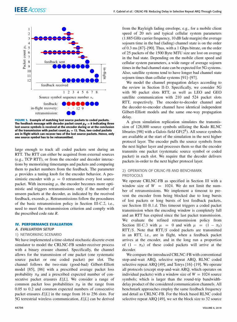
The encoder checks if the lost source packets indicated bythe feedback with decoder packet count pd could have beenrecovered by the packets in flight, i.e., the packets that havebeen transmitted since the packet transmission with packetcount pd . Each lost source packet marked in the feedbackis matched to a coded packet that includes the lost sourcepacket. If there is no matching coded packet, then recoveryis impossible and a retransmission is necessary, as illustratedfor an examplewith three lost source packets and two in-flightcoded packets in Fig. 3.For each source symbol se in the encoding window,
the encoder tracks the packet count pe(se) of the transmittedpacket that contained the source symbol se. The encoderalso tracks the packet counts pe of the µ, µ ≥ 0, mostrecently transmitted coded packets. Ideally, µ is selected
VOLUME 6, 2018 44793
F. Gabriel et al.: CRLNC-FB: Reducing Delay in Selective Repeat ARQ Through Coding
FIGURE 3. Example of matching lost source packets to coded packets.The feedback message with decoder packet count pd = 8 indicating threelost source symbols is received at the encoder during or at the conclusionof the transmission with packet count pe = 12. Thus, two coded packetsare in flight which can recover two of the lost source packets. Hence, onlyone source symbol has to be retransmitted.
large enough to track all coded packets sent during anRTT. The RTT can either be acquired from external sources(e.g., TCP RTT), or from the encoder and decoder interac-tions by memorizing timestamps and packets and comparingthem to packet numbers from the feedback. The parameterµ provides a tuning knob for the encoder behavior. A pes-simistic encoder with µ = 0 retransmits every lost sourcepacket. With increasing µ, the encoder becomes more opti-mistic and triggers retransmissions only if the number ofunseen packets at the decoder, as indicated by the receivedfeedback, exceeds µ. Retransmissions follow the proceduresof the basic retransmission policy in Section III-C.2, i.e.,need to meet the retransmission criterion and comply withthe prescribed code rate R.
IV. PERFORMANCE EVALUATIONA. EVALUATION SETUP1) NETWORKING SCENARIOWe have implemented a time-slotted stochastic discrete eventsimulator to model the CRLNC-FB sender-receiver processwith a binary erasure channel. Specifically, the channelallows for the transmission of one packet (one systematicsource packet or one coded packet) per slot. Thechannel follows the two-state (good-bad) Gilbert-Elliottmodel [85], [86] with a prescribed average packet lossprobability πB and a prescribed expected number of con-secutive packet erasures E[L]. We consider a range ofcommon packet loss probabilities πB in the range from0.05 to 0.2 and common expected numbers of consecutivepacket erasures E[L] in the range from 16 to 256 slots. For5G terrestrial wireless communication, E[L] can be derived
from the Rayleigh fading envelope, e.g., for a mobile clientspeed of 20 m/s and typical cellular system parameters(1.885GHz carrier frequency, 10 dB fademargin) the averagesojourn time in the bad (fading) channel state is on the orderof 0.3 ms [87]–[90]. Thus, with a 1 Gbps bitrate, on the orderof 25 packets of the 1500 Byte MTU size are lost on averagein the bad state. Depending on the mobile client speed andcellular system parameters, a wide range of average sojourntimes in the bad channel state can be expected for 5G systems.Also, satellite systems tend to have longer bad channel statesojourn times than cellular systems [91]–[97].
We model the channel propagation delays according tothe review in Section II-D. Specifically, we consider 5Gwith 90 packet slots RTT, as well as LEO and GEOsatellite communication with 210 and 524 packet slotsRTT, respectively. The encoder-to-decoder channel andthe decoder-to-encoder channel have identical independentGilbert-Elliott models and the same one-way propagationdelay.
A given simulation replication simulates the transmis-sion of 128,000 source symbols utilizing the Kodo RLNClibraries [98] with a Galois field GF(28). All source symbolsare available at the start of the simulation in the next higherprotocol layer. The encoder pulls the source symbols fromthe next higher layer and processes them so that the encodertransmits one packet (systematic source symbol or codedpacket) in each slot. We require that the decoder deliverspackets in-order to the next higher protocol layer.
2) OPERATION OF CRLNC-FB AND BENCHMARKPROTOCOLSWe operate CRLNC-FB as specified in Section III with awindow size of W = 1024. We do not limit the num-ber of retransmissions. We implement a timeout to pre-vent the encoder from being blocked due to long burstsof lost packets or long bursts of lost feedback packets,see Section III-B.1.d. This timeout triggers a coded packettransmission when the encoding window is completely fulland an RTT has expired since the last packet transmission.We evaluate the refined retransmission policy fromSection III-C.3 with µ = 0 and with µ = (1 − πb)RTT/S. Note that RTT/S coded packets are transmittedin an RTT, i.e., are in flight, when a feedback packetarrives at the encoder, and in the long run a proportionof (1 − πb) of these coded packets will arrive at thedecoder.
We compare the introduced CRLNC-FBwith conventionalstop-and-wait ARQ, selective repeat ARQ, RLNC codedselective repeat ARQ [49], and Tetrys [16]–[19]. We operateall protocols (except stop-and-wait ARQ, which operates onindividual packets) with a window size of W = 1024 sourcesymbols; which is larger than the round-trip bandwidth-delay product of the considered communication channels. Allbenchmark approaches employ the same feedback frequencyand detail as CRLNC-FB. For the block based RLNC codedselective repeat ARQ [49], we set the block size to 32 source
44794 VOLUME 6, 2018

F. Gabriel et al.: CRLNC-FB: Reducing Delay in Selective Repeat ARQ Through Coding
symbols and the window size to 32 blocks. For Tetryswe modified the timeout for preventing encoder blocking(see Section III-B.1.d) to transmit as many additional codedpackets as there are currently unacknowledged source sym-bols in the encoding window.
3) PERFORMANCE METRICSWe define the in-order delay D as the time duration fromthe time instant when a packet would have been deliveredwithout any losses to the time instant when the packet isactually delivered to the next higher protocol layer. Thetotal delay of a source packet from the time instant whenit is pulled by the encoder from the next higher protocollayer to the time instant when the packet is delivered by thedecoder to the next higher protocol layer is then the consid-ered in-order delay D plus the transmission time of one slot,plus the one-way channel propagation delay. We neglect theRLNC encoding and decoding computation time [99]–[101].We report the 99 percentile of the in-order delayD. We definethe throughput as the ratio of the total number of sourcesymbols to be transmitted to the total number time slotsrequired to complete the delivery to the next higher protocollayer at the decoder.
We define efficiency as the ratio of the total num-ber of innovative packets (in the conventional sense ofRLNC coding [102], [103]) received by the decoder to thetotal number of packets received by the decoder. Ideally,every packet received by the decoder should be innovativewhich corresponds to an efficiency of 1.0.
For each given evaluation scenario, we simulate 100 inde-pendent replications of the transmission of 128,000 sourcesymbols. The resulting 95% confidence intervals are smallerthan 2% of the sample means and are omitted from the plotsto avoid clutter.
B. CRLNC-FB VARIANTSFig. 4 compares the throughput-delay performance of vari-ants of the CRLNC-FB protocol. In particular, we com-pare CRLNC-FB utilizing the novel band-form Gaussianelimination RLNC decoding with the conventional forwardGaussian elimination (FGE) RLNC decoding in the contextof the CRLNC-FB protocol. These two CRLNC-FB vari-ants consider µ = 0 in-flight packets and are comparedwith CRLNC-FB-Opt with band-form Gaussian eliminationwith µ = (1 − πb)RTT/S considered in-flight packets(see Section III-C.3). Moreover, we compare with aCRLNC-FB variant (with band-form Gaussian elimina-tion and µ = 0) that retransmits only coded packets(CRLNC-FB-Cod). That is, the coded variant transmits acoded packet (generated from all presently unacknowledgedsource symbols) for each lost source symbol while enforc-ing the retransmission criterion from Section III-C.2 forcoded packets transmitted in response to lost source symbols.The throughput-delay curves are obtained by evaluating thethroughput and 99 percentile delay metrics for the code ratesR = S/(S + 1) corresponding to S = 1, 2, 4, 8, 16, and 32.
FIGURE 4. Throughput and 99%tile of packet delay of different CRLNC-FBvariants for range of code rates R = S/(S + 1) corresponding toS = 1,2,4,8,16,32 source packets between coded packets forLEO (RTT = 210 slots) with E [L] = 64 successive packet lossesand for 5G (RTT = 90 slots) with E [L] = 256 successive packetlosses; Fixed packet loss probability πB = 10%.
1) BAND MATRIX CRLNC-FB VS. FORWARD GAUSSIANELIMINATIONWe observe from Fig. 4 that for the E[L] = 256 (longloss burst) channel scenario, the FGE variant gives higher99 percentile packet delays than CRLNC-FB with band-formGaussian elimination. This difference is most pronouncedfor high code rates that approach one and give throughputsabove 0.8. We observe from Fig. 4 that for the E[L] =64 scenario the band-form decoding gives essentially thesame delays as conventional forward Gaussian eliminationdecoding; we have confirmed this result also for E[L] = 16(short loss burst) channel scenarios in additional evaluationsthat are not included here to avoid clutter. Long loss burstsE[L] drop many successive source symbols that can typicallynot be recovered from the coded packets when the code rateR is high, i.e., when there are relatively few coded packetsinterspersed among the source packets. Thus, retransmissionsare needed to recover the lost source packets. As illustratedin Fig. 2(c), the band-form decoding approach requests theretransmission of the systematic source packets at the begin-ning of a loss burst. Upon the receipt of the retransmittedsystematic source packets, the decoder can immediately for-ward the source packets (in-order) to the higher layers with-out waiting for the decoding matrix to achieve full rank. Incontrast, the forward Gaussian elimination decoding, as illus-trated in Fig. 2(a), requests the lost source symbols from thetail end of a loss burst, and requires that the decoding matrixachieves full rank in order to recover the lost source packetsfrom the beginning of the loss burst. For long loss bursts andcorrespondingly numerous lost source packets, achieving fullrank requires the receipt of numerous retransmitted packets,which adds delays as observed in Fig. 4.Moreover, upon the receipt of the retransmitted systematic
source packets with the band-form approach, the decodingand encoding windows can be closed on the received packets,advancing the windows and enabling the transmission of newsource packets. In particular, with the band-form approach,the windows advance at the granularity of individual source
VOLUME 6, 2018 44795

F. Gabriel et al.: CRLNC-FB: Reducing Delay in Selective Repeat ARQ Through Coding
symbols, whereas with the forward Gaussian elimination,the windows advance later and in steps of multiple sourcesymbols (according to the loss pattern). In the example inFig. 2(c) the receipt of the retransmitted systematic sourcesymbol with sequence number 2 allows the decoder to deliverthis source symbol to the next higher layer and to closethe decoding window on this source symbol. The corre-sponding feedback packet acknowledges that the decoderhas seen source symbol 2. Upon receipt of this feedbackpacket, the encoder can close its window on source symbol 2.Upon the receipt of the retransmitted systematic sourcesymbol 3, the decoding matrix in Fig. 2(c) reaches full rank,hence source symbols 3–8 can be delivered to the next higherlayer and the decoding window and the encoding window(after receipt of the corresponding feedback) can be closedon these symbols. In contrast, with forward Gaussian elimi-nation, the receipt of retransmitted systematic source symbol4 does not result in the delivery of any source symbols tothe next higher layer, neither in an advance of the encodingwindow. Rather, the encoding window in forward Gaussianelimination only closes on the decoded source symbols (seeSection III-B.2.a), i.e., in the example in Fig. 2(a), the encod-ing window still covers source symbols 2–9 after the receiptof the feedback corresponding to the receipt of retransmittedsource symbol 4. Only after the receipt of the retransmittedsource symbol 5 does the decoding matrix reach full rank,allowing for the recovery of source symbols 2 and 3, thedelivery of source symbols 2–8 to the higher layer, the closingof the decoding window on source symbols 2–8, and theclosing of the encoding window on source symbols 2–8 afterreceipt of the corresponding feedback packet. Thus, the band-form Gaussian elimination delivers some source symbolsearlier than the forward Gaussian elimination and reduces theinstances of the encoder being blocked from further transmis-sions due to a full window.
2) CRLNC-FB WITH OPTIMISTIC RETRANSMISSION POLICYWe also observe from Fig. 4 that optimistically consideringthe in-flight packets for the recovery of the lost source packetsin CRLNC-FB-Opt generally reduces the throughput-delayperformance. This is mainly because the optimistic consid-eration of the in-flight packets delays retransmissions. Thiseffect of delaying retransmissions outweighs the advantagesthat come from sending more new source packets (insteadof retransmissions); especially for practical window sizesthat limit the number of in-flight packets to less than a fewtimes the bandwidth-delay product. However, we observefrom Fig. 5 that considering the in-flight packets very slightlyimproves the efficiency. In additional evaluations that arenot included to avoid clutter, we found that high packet lossprobabilities, long propagation delays, and large windowsWgenerally increase the efficiency gain achieved by optimisti-cally considering the in-flight packets (CRLNC-FB-Opt)over the basic CRLNC-FB that ignores the in-flight pack-ets when deciding on retransmissions. For instance, forthe GEO channel with a 20% packet loss probability
FIGURE 5. Efficiency of different CRLNC-FB variants as a function ofnumber S of successive source symbols between coded packets for LEO(RTT = 210 slots) with a mean of E [L] = 64 successive packet losses forπB = 10% loss.
(independently for each slot) and a window of W = 4096,the efficiencies are 0.784 vs. 0.748 for R = 2/3, and 0.885vs. 0.870 for R = 4/5 for CRLNC-FB-Opt vs. CRLNC-FB.Thus, the efficiency gains (which correspond to reducedenergy consumption) from the optimistic consideration of thein-flight packets are small to modest and need to be carefullyweighed against the delay increases.
3) CRLNC-FB WITH CODED PACKET RETRANSMISSIONSWe observe from Fig. 4 that transmitting coded packetsin the band-form Gaussian elimination (CRLNC-FB-Cod)instead of retransmitting systematic source packets givesslightly lower throughput-delay performance than the for-ward Gaussian elimination approach with systematic packetretransmissions (CRLNC-FB-FGE). In scenarios with onepacket loss burst in the window, CRLNC-FB-Cod andCRLNC-FB-FGE have the same dynamics. In the example inFig. 2(c), transmitting two coded packets instead of retrans-mitting the systematic source symbols 2 and 3, requires thereceipt of both coded packets before the decoding matrixreaches full rank and before any symbols can be delivered andwindows advanced. Specifically, after the receipt of the firstcoded packet, source symbol 3 is considered as seen, whilesource symbol 2 is still unseen.
CRLNC-FB-FGE can have an advantage over CRLNC-FB-Cod when there are two or more packet loss bursts inthe window. In particular, imagine the scenario in Fig. 2(a)being duplicated in a doubled window covering sourcesymbols 1–16, whereby source symbols 4 and 5 aswell 12 and 13 are unseen, while the other sourcesymbols 1–3, 6–11, and 14–16 are seen. Then, the receiptof the retransmitted source symbols 4 and 5 allows for therecovery of source symbols 2 and 3 in CRLNC-FB-FGE.In contrast, in CRLNC-FB-Cod, the receipt of two codedpackets does not allow for the recovery of any sourcesymbols, rather all four coded packets would need tobe received and the entire decoding matrix would needto achieve full rank before any source symbols can berecovered.
44796 VOLUME 6, 2018

F. Gabriel et al.: CRLNC-FB: Reducing Delay in Selective Repeat ARQ Through Coding
FIGURE 6. Throughput and 99%tile packet delay for LEO (RTT = 210 slots) with πB = 5% loss for range of mean number of successive packet losses E [L]for code rate R = S/(S + 1) corresponding to S = 1,2,4,8,16,32. Results outside the plotted range are summarized in captions. (a) E [L] = 16; Tetrysreaches 0.88 throughput for 2400 slots delay. (b) E [L] = 64; Tetrys reaches 0.87 throughput for 7400 slots delay. (c) E [L] = 256; SW-ARQ has 420 slotsdelay; Tetrys reaches 0.86 throughput for delays exceeding 10000 slots.
FIGURE 7. Throughput and 99%tile delay for πB = 10% loss and a mean of E [L] = 64 successive packet losses. (a) 5G (RTT = 90 slots); SW-ARQ has180 slots delay; Tetrys reaches 0.79 throughput for 3800 slots delay. (b) LEO (RTT = 210 slots); Tetrys reaches 0.78 throughput for 4100 slots delay.(c) GEO (RTT = 524 slots); Tetrys reaches 0.75 throughput delays exceeding 10000 slots.
For the remainder of this study we consider CRLNC-FBwith the band-form Gaussian elimination RLNC decodingand µ = 0 considered in-flight packets.
C. THROUGHPUT-DELAY RESULTS1) CRLNC-FB VS. STOP-AND-WAIT ARQIn Figs. 6 and 7 we plot the throughput-delay curves forCRLNC-FB and its benchmarks. Stop-and-wait ARQ (SW-ARQ) achieves low delay, but also very low throughput asonly one packet at a time is pulled from the next higher layerat the sender. One RTT after a packet transmission, either anacknowledgement arrives at the sender to confirm the packetreception at the receiver (if there are no losses), or the time-out (see Section III-B.1.d) triggers a retransmission. Thus,the throughput is upper bounded by one source symbol perone RTT, while the efficiency is one. Network coding witha low code rate R = 1/2, which corresponds to the left-most point on the throughput-delay curves, sends one codedpacket for each systematic source symbol. Accordingly, the
throughput is upper bounded by one half. For short loss bursts(E[L] = 16), see Fig. 6(a), the delay of network coding withR = 1/2 is slightly below the delay for stop-and-wait ARQas the coded packets recover lost packets at the decoder if thenumber of received coded packets exceeds the number of lostsource symbols in the window.
On the other hand, for long loss bursts (E[L] = 64and 256), see Figs. 6(b) and (c), stop-and-wait ARQ hasa lower delay than the RLNC approaches with R = 1/2as explained in the following. According to the recommen-dations for the transmission control protocol (TCP) [82],we consider a single retransmit timer, see Section III-B.1.d.Consider a source packet transmitted for the first time whena long loss burst (on the encoder-to-decoder channel) starts(while the decoder-to-encoder channel is lossfree and therehave been no prior losses on the encoder-to-decoder channel).Stop-and-wait ARQ will repeatedly retransmit this packetuntil it is successfully delivered and acknowledged when theloss burst ends. In contrast, the encoder in the window-based
VOLUME 6, 2018 44797

F. Gabriel et al.: CRLNC-FB: Reducing Delay in Selective Repeat ARQ Through Coding
RLNC approaches will keep pulling source packets from thenext higher layer and transmit the packets (until the window isfull). The single timer for the oldest unacknowledged packettriggers retransmissions of the oldest unacknowledged packetuntil this packet is successfully received and the correspond-ing feedback packet reaches the encoder. The encoder thenretransmits the lost source symbols. Thus, these subsequentsource packets in the window (after the oldest unacknowl-edged packet) are delayed by the loss burst (whereas withstop-and-wait ARQ these subsequent packets are pulled fromthe next higher layer after the end of the loss burst).
2) CRLNC-FB VS. SELECTIVE REPEAT ARQGenerally, we observe for all network coding approachesin Fig. 6 increasing delays for increasing code rateR. A highercode rate R implies fewer coded packets that could be used torecover lost source packets. Thus, more retransmissions areneeded, increasing the delays. We observe from Fig. 6 thatfor very high codes ratesR that approach one, the CRLNC-FBthroughput-delay approaches the throughput-delay of selec-tive repeat ARQ. For increasing code rates R = S/(S + 1)there are more and more systematic source symbols Sbetween two coded packets. Thus, for very large S, the codedpackets become negligible and CRLNC-FB degenerates toselective repeat ARQ. Selective repeat ARQ achieves themaximum possible efficiency by minimizing the number ofunnecessary packet transmissions. Unnecessary packet trans-missions occur with selective repeat ARQ only if feedbackpackets are lost and trigger a timeout to prevent encoderblocking, see Section III-B.1.d.With a perfect feedback chan-nel, selective repeat ARQwould achieve an efficiency of one.We also observe that selective repeat ARQ achieves a fairlyhigh throughput, although the RLNC approaches can achievea higher throughput. In particular, for the long propagationdelay GEO channel [see Fig. 7(c)], retransmissions are verytime consuming, reducing the throughput. Thus, recoveryof lost packets through RLNC can achieve higher through-put than relying only on retransmissions, as selective repeatARQ does.
Nevertheless, in these cases where the RLNC throughputis higher than the selective repeat ARQ throughput, CRLNC-FB still converges to selective repeat ARQ as the coderate R increases. Thus, in these cases, CRLNC-FB exhibitsdecreasing throughput and increasing delay as the code rateR increases towards one. Intuitively, for high code rates Rthere are too few coded packets to recover the lost packetsat the decoder. Hence, with increasing code rate R, more andmore retransmissions are requested through feedback. Theseretransmissions add an additional RTT (or several RTTs forrepeated retransmissions), increasing the delay. These delayincreases accumulate to increase the overall time duration fordelivering a set of packets and thus reduce the throughput.Moreover, for channels with high RTT, the more frequentretransmissions increase the likelihood of old unacknowl-edged source symbols preventing the encoding window fromadvancing. When the encoding window cannot advance due
to old unacknowledged packets, then additional time slotselapse (without being utilized for transmissions), increasingthe total number of required slots, and hence reducing thethroughput.
3) CRLNC-FB VS. BLOCK BASED RLNCWe observe from Fig. 6 that block based RLNC coded selec-tive repeat ARQ [49], gives significantly lower throughputdelay performance than CRLNC-FB. Block based RLNCgenerally increases the delay compared to sliding win-dow RLNC, i.e., the block based RLNC throughput delaycurves are to the right (towards higher delays) comparedto CRLNC-FB. These delay increases are mainly dueto the block-by-block granularity of the RLNC encod-ing and decoding, i.e., a full block of source symbols isencoded or decoded at a time. In contrast, sliding windowRLNC can advance the encoding and decoding windows ata granularity of a single source symbol, and thus inherentlyachieve lower delays. The delay introduced due to the blockgranularity can be reduced by reducing the block size. How-ever, for a prescribed code rate R = S/(S + 1), the block sizecannot be smaller than S.
4) CRLNC-FB VS. TETRYSWe observe from Fig. 6 that CRLNC-FB gives higherthroughput-delay performance than Tetrys, especially forlong loss bursts E[L]. Tetrys conforms to the prescribedcode rate R throughout the retransmission process. If mul-tiple successive source packets, say ` packets, are lost, thenTetrys needs to transmit `S new systematic (uncoded) sourcesymbols along with the ` coded packets required to recoverthe ` lost source packets. For moderate to large S, i.e., formoderate to high code rates R, this transmission of the codedpackets interspersed with the transmission of new sourcepackets adds significant delays. Importantly, due to the in-order delivery requirement, the receiver needs to buffer the`S systematic source packets until the preceding ` lostpackets can be recovered from the ` received coded pack-ets. CRLNC-FB avoids these additional delays by directlyretransmitting the lost source symbols, along with the cor-responding coded packets according to the prescribed coderate R.A related important aspect for understanding the Tetrys
dynamics is that the Tetrys encoding window is allowed tocover non-consecutive source symbols. Thus, Tetrys doesnot require that the ` lost source symbols along with the`S source symbols (required for generating enough codedpackets for recovering the ` lost symbols) fit into the encodingwindow W . Rather, Tetrys continues loss-free operation aslong as the ` lost source symbols and the currently unac-knowledged in-flight source symbols (up to RTT sourcesymbols) fit into the encoding window. Several RTTs worthof source symbols may be required to generate enoughcoded packets to recover the ` lost symbols. In contrast, theCRLNC-FB encoding window covers up to W consecutivesource symbols.
44798 VOLUME 6, 2018
F. Gabriel et al.: CRLNC-FB: Reducing Delay in Selective Repeat ARQ Through Coding
When packet losses occur towards the end of a file trans-mission there may not be enough source symbols left inthe file to generate enough coded packets to recover fromthe losses. In such a case, Tetrys can rely on the time-out for preventing encoder blocking (see Sections III-B.1.dand IV-A.2) to generate additional coded packets.Overall, the Tetrys throughput-delay performance is dom-
inated by the mean duration E[L] of loss bursts, as observedfrom Fig. 6. The Tetrys recovery of lost packets with codedpackets interspersed at a fixed code rate R = S/(S+1) amongnew source packets essentially amplifies the delay effects ofa burst of ` lost packets by a factor of S. This delay effectcould be mitigated by adapting the code rate R, e.g., reduceR = S/(S + 1) by reducing S, at the expense of the com-plexity of an adaptation algorithm [18]. An adaptive form ofTetrys could thus operate at the most suitable point along thethroughput-delay curve. On the other hand, we observe fromFig. 7 that Tetrys is relatively insensitive to the RTT, whilethe throughput-delay performance of the other approaches issensitive to both the RTT and the loss burst duration.
V. CONCLUSIONWe have developed and evaluated Caterpillar RLNC withFeedback (CRLNC-FB). CRLNC-FB combines finite slidingwindow RLNC for forward error correction with feedbackbased selective repeat Automatic Repeat Request (ARQ)retransmission of lost source symbols. Extensive perfor-mance evaluations for erasure channels with bursty packetloss patterns have indicated that CRLNC-FB has higherthroughput-delay performance than the prior approachescombining finite sliding window RLNC with feedbackbased retransmissions. In particular, CRLNC-FB achieveslower delays than the block based RLNC with feedbackbased transmission of coded packets [49] through the fine-granular advancement of the finite sliding coding window byindividual source symbols. CRLNC-FB achieves higherthroughput-delay performance than the Tetrys approach,which transmits new source symbols and coded packetsaccording to a prescribed code rate in response to feed-back [16]–[19], by retransmitting the lost source symbols inuncoded (systematic) form to promote fast in-order deliveryat the receiver.
There are several important directions for future researchrelated to CRLNC-FB. While this study considered a singlewireless hop, an important future research direction is toexamine recoding in multi-hop wireless networks, e.g., wire-less mesh networks. Recoding at intermediate nodes couldstrengthen the FEC for subsequent highly lossy wirelesshops. Recoding could also enhance mesh network transportwhere a given stream may send packets over multiple paths.Another direction is to examine finite sliding window RLNCwith feedback in the context of multiple traffic flows. Morespecifically, this study considered the intra-coding of a singletraffic flow. Future research could examine the inter-codingof multiple traffic flows to enhance the overall transportcapability of lossy networks.
REFERENCES[1] H. Alshaheen and H. Takruri-Rizk, ‘‘Energy saving and reliability
for wireless body sensor networks (WBSN),’’ IEEE Access, vol. 6,pp. 16678–16695, 2018.
[2] I. Achour, T. Bejaoui, A. Busson, and S. Tabbane, ‘‘Network codingscheme behavior in a vehicle-to-vehicle safety message dissemination,’’in Proc. IEEE ICC Workshops, May 2017, pp. 441–446.
[3] H. Kang, H. Yoo, D. Kim, and Y.-S. Chung, ‘‘CANCORE: Context-aware network coded repetition for VANETs,’’ IEEE Access, vol. 5,pp. 3504–3512, 2017.
[4] J.-S. Liu, C.-H. R. Lin, and J. Tsai, ‘‘Delay and energy tradeoff inenergy harvestingmulti-hopwireless networkswith inter-session networkcoding and successive interference cancellation,’’ IEEE Access, vol. 5,pp. 544–564, 2016.
[5] F. A. Monteiro et al., ‘‘Special issue on network coding,’’ EURASIP J.Adv. Signal Process., vol. 2017, no. 29, pp. 29-1–29-3, Apr. 2017.
[6] A. Nessa, M. Kadoch, and B. Rong, ‘‘Fountain coded cooperative com-munications for LTE-A connected heterogeneous M2M network,’’ IEEEAccess, vol. 4, pp. 5280–5292, 2016.
[7] H. V. Nguyen, S. X. Ng, W. Liang, P. Xiao, and L. Hanzo, ‘‘A network-coding aided road-map of large-scale near-capacity cooperative commu-nications,’’ IEEE Access, vol. 6, pp. 21592–21620, 2018.
[8] B. Tang and S. Yang, ‘‘An LDPC approach for chunked network codes,’’IEEE/ACM Trans. Netw., vol. 26, no. 1, pp. 605–617, Feb. 2018.
[9] R. Torrea-Duran, M. M. Céspedes, J. Plata-Chaves, L. Vandendorpe, andM. Moonen, ‘‘Topology-aware space-time network coding in cellularnetworks,’’ IEEE Access, vol. 6, pp. 7565–7578, 2018.
[10] Y. Yang, W. Chen, O. Li, and L. Hanzo, ‘‘Joint rate and power adaptationfor amplify-and-forward two-way relaying relying on analog networkcoding,’’ IEEE Access, vol. 4, no. 1, pp. 2465–2478, 2016.
[11] Y. Yang, W. Chen, O. Li, Q. Liu, and L. Hanzo, ‘‘Truncated-ARQ aidedadaptive network coding for cooperative two-way relaying networks:Cross-layer design and analysis,’’ IEEE Access, vol. 4, pp. 9361–9376,2016.
[12] R. Bassoli, H. Marques, J. Rodriguez, K. W. Shum, and R. Tafazolli,‘‘Network coding theory: A survey,’’ IEEE Commun. Surveys Tuts.,vol. 15, no. 5, pp. 1950–1978, 4th Quart., 2013.
[13] M. Z. Farooqi, S. M. Tabassum, M. H. Rehmani, and Y. Saleem, ‘‘A sur-vey on network coding: From traditional wireless networks to emergingcognitive radio networks,’’ J. Netw. Comput. Appl., vol. 46, pp. 166–181,Nov. 2014.
[14] J. Cloud and M. Médard, ‘‘Network coding over SATCOM: Lessonslearned,’’ in Proc. Int. Conf. Wireless Satell. Syst. Cham, Switzerland:Springer, 2015, pp. 272–285.
[15] X. Li, Q. Chang, and Y. Xu, ‘‘Queueing characteristics of the best effortnetwork coding strategy,’’ IEEE Access, vol. 4, pp. 5990–5997, 2016.
[16] J. Detchart, E. Lochin, J. Lacan, and V. Roca, Tetrys, An On-the-Fly Net-work Coding Protocol, document draft-detchart-nwcrg-tetrys-04, IETF,Internet-Draft, Mar. 2018.
[17] T. T. Thai, E. Lochin, and J. Lacan, ‘‘Online multipath convolutionalcoding for real-time transmission,’’ in Proc. IEEE Int. Packet VideoWorkshop (PV), May 2012, pp. 41–46.
[18] T. T. Thai, J. Lacan, and E. Lochin, ‘‘Joint on-the-fly network cod-ing/video quality adaptation for real-time delivery,’’ Signal Process.,Image Commun., vol. 29, no. 4, pp. 449–461, Apr. 2014.
[19] P. U. Tournoux, E. Lochin, J. Lacan, A. Bouabdallah, and V. Roca,‘‘On-the-fly erasure coding for real-time video applications,’’ IEEETrans. Multimedia, vol. 13, no. 4, pp. 797–812, Aug. 2011.
[20] J. Barros, R. A. Costa, D. Munaretto, and J. Widmer, ‘‘Effective delaycontrol in online network coding,’’ in Proc. IEEE INFOCOM, Apr. 2009,pp. 208–216.
[21] J. Cloud andM.Médard, ‘‘Multi-path low delay network codes,’’ in Proc.IEEE GLOBECOM, Dec. 2016, pp. 1–7.
[22] A. Garcia-Saavedra, M. Karzand, and D. J. Leith, ‘‘Low delay randomlinear coding and scheduling over multiple interfaces,’’ IEEE Trans.Mobile Comput., vol. 16, no. 11, pp. 3100–3114, Nov. 2017.
[23] M. Karzand and D. J. Leith, ‘‘Low delay random linear coding overa stream,’’ in Proc. Annu. Allerton Conf. Commun., Control, Comput.(Allerton), Sep. 2014, pp. 521–528.
[24] M. Karzand, D. J. Leith, J. Cloud, and M. Médard, ‘‘Design of FECfor low delay in 5G,’’ IEEE J. Sel. Areas Commun., vol. 35, no. 8,pp. 1783–1793, Aug. 2017.
VOLUME 6, 2018 44799

F. Gabriel et al.: CRLNC-FB: Reducing Delay in Selective Repeat ARQ Through Coding
[25] M. Esmaeilzadeh, P. Sadeghi, and N. Aboutorab, ‘‘Random linear net-work coding for wireless layered video broadcast: General design meth-ods for adaptive feedback-free transmission,’’ IEEE Trans. Commun.,vol. 65, no. 2, pp. 790–805, Feb. 2017.
[26] P. Ostovari, J. Wu, and A. Khreishah, ‘‘Cooperative Internet access usinghelper nodes and opportunistic scheduling,’’ IEEE Trans. Veh. Technol.,vol. 66, no. 7, pp. 6439–6448, Jul. 2017.
[27] V. Roca, B. Teibi, C. Burdinat, T. Tran-Thai, and C. Thienot,‘‘Block or convolutional AL-FEC codes? A performance comparisonfor robust low-latency communications,’’ Inria, Rocquencourt, France,Tech. Rep. hal-01395937v2, 2017.
[28] V. Roca, B. Teibi, C. Burdinat, T. Tran-Thai, and C. Thienot, ‘‘Lesslatency and better protection with AL-FEC sliding window codes:A robust multimedia CBR broadcast case study,’’ in Proc. IEEE Int. Conf.Wireless Mobile Comput., Netw. Commun. (WiMob), Oct. 2017, pp. 1–8.
[29] B. Sun, C. Gui, Y. Song, H. Chen, and X. Zhu, ‘‘Performance analysisof sliding window network coding in MANET,’’ in Proc. Adv. Comput.Archit. Conf. Singapore: Springer, 2016, pp. 174–183.
[30] S. Wunderlich, F. Gabriel, S. Pandi, F. H. P. Fitzek, and M. Reisslein,‘‘Caterpillar RLNC (CRLNC): A practical finite sliding window RLNCapproach,’’ IEEE Access, vol. 5, pp. 20183–20197, 2017.
[31] Y. Zeng, X. Xu, and R. Zhang, ‘‘Trajectory design for completion timeminimization in UAV-enabled multicasting,’’ IEEE Trans. Wireless Com-mun., vol. 17, no. 4, pp. 2233–2246, Apr. 2018.
[32] IEEE Standard for Information Technology—Telecommunications andInformation Exchange Between Systems—Local and Metropolitan AreaNetworks—Specific Requirements—Part 11: Wireless LAN MediumAccess Control (MAC) and Physical Layer (PHY) Specifications, IEEEStandard, IEEE 802.11 Working Group, 2012.
[33] H. Inamura, O. Takahashi, H. Nakano, T. Ishikawa, and H. Shigeno,‘‘Impact of layer two ARQ on TCP performance inW-CDMA networks,’’in Proc. Int. Conf. Distrib. Comput. Syst., 2004, pp. 284–291.
[34] E. Cabrera, G. Fang, and R. Vesilo, ‘‘Adaptive hybrid ARQ (A-HARQ)for ultra-reliable communication in 5G,’’ in Proc. IEEE Veh. Technol.Conf. (VTC Spring), Jun. 2017, pp. 1–6.
[35] S. Lin and D. J. Costello, Error Control Coding. New York, NY, USA:Pearson, 2004.
[36] E. Malkamaki, D. Mathew, and S. Hamalainen, ‘‘Performance of hybridARQ techniques for WCDMA high data rates,’’ in Proc. IEEE Veh.Technol. Conf. (VTC Spring), vol. 4, May 2001, pp. 2720–2724.
[37] V. Shah-Mansouri and S. Srinivasan, ‘‘Retransmission scheme for intra-session linear network coding in wireless networks,’’ Int. J. Adv. Intell.Paradigms, vol. 9, no. 4, pp. 326–346, 2017.
[38] I. Tsokalo, F. Gabriel, S. Pandi, F. H. P. Fitzek, and R. Lehnert, ‘‘Reli-able feedback mechanisms for routing protocols with network cod-ing,’’ in Proc. IEEE Int. Symp. Power Line Commun. Appl., Apr. 2018,pp. 1–7.
[39] Y.-J. Chen, L.-C. Wang, K. Wang, and W.-L. Ho, ‘‘Topology-awarenetwork coding for wireless multicast,’’ IEEE Syst. J., to be published.
[40] B. Chen et al., ‘‘Packet multicast in cognitive radio ad hoc networks:A method based on random network coding,’’ IEEE Access, vol. 6,pp. 8768–8781, 2018.
[41] E. Drinea, L. Keller, and C. Fragouli, ‘‘Real-time delay with networkcoding and feedback,’’ Phys. Commun., vol. 6, pp. 100–113, Mar. 2013.
[42] T. Niu, Z. Chen, D. Zhang, and K. Xu, ‘‘On minimizing average packetsdecoding delay based on B-DLNC for wireless broadcasting,’’ in Proc.IEEE Int. Conf. Commun. Technol. (ICCT), Oct. 2017, pp. 815–820.
[43] M. Yu, A. Sprintson, and P. Sadeghi. (2018). ‘‘On the packet decodingdelay of linear network coded wireless broadcast.’’ [Online]. Available:https://arxiv.org/abs/1802.02727
[44] G. Hu, K. Xu, and Y. Xu, ‘‘ARNC multicasting of HDCP data forcooperative mobile devices with dual interfaces,’’ IEEE Commun. Lett.,vol. 21, no. 11, pp. 2504–2507, Nov. 2017.
[45] N. Papanikos and E. Papapetrou, ‘‘Deterministic broadcasting and ran-dom linear network coding in mobile ad hoc networks,’’ IEEE/ACMTrans. Netw., vol. 25, no. 3, pp. 1540–1554, Jun. 2017.
[46] M. E. Migabo, T. O. Olwal, K. Djouani, and A. M. Kurien, ‘‘Cooperativeand adaptive network coding for gradient based routing in wireless sensornetworks with multiple sinks,’’ J. Comput. Netw. Commun., vol. 2017,Oct. 2017, Art. no. 5301462-1–5301462-10.
[47] X. Xu, Y. L. Guan, Y. Zeng, and C.-C. Chui, ‘‘Spatial-temporal networkcoding based on BATS code,’’ IEEE Commun. Lett., vol. 21, no. 3,pp. 620–623, Mar. 2017.
[48] F.Wu, C. Hua, H. Shan, andA. Huang, ‘‘Reliable network coding formin-imizing decoding delay and feedback overhead in wireless broadcasting,’’in Proc. IEEE Int. Symp. Pers. Indoor Mobile Radio Commun. (PIMRC),Sep. 2012, pp. 796–801.
[49] J. Cloud, D. Leith, and M. Médard, ‘‘A coded generalization of selectiverepeat ARQ,’’ in Proc. IEEE INFOCOM, Apr./May 2015, pp. 2155–2163.
[50] S. Gheorghiu, A. L. Toledo, and P. Rodriguez, ‘‘Multipath TCP with net-work coding for wireless mesh networks,’’ in Proc. IEEE ICC, May 2010,pp. 1–5.
[51] P. Karafillis, K. Fouli, A. ParandehGheibi, andM.Médard, ‘‘An algorithmfor improving sliding window network coding in TCP,’’ in Proc. IEEEConf. Inf. Sci. Syst., Mar. 2013, pp. 1–5.
[52] Y. Lin, B. Liang, and B. Li, ‘‘SlideOR: Online opportunistic networkcoding inwirelessmesh networks,’’ inProc. IEEE INFOCOM,Mar. 2010,pp. 1–5.
[53] D. Malak, M. Médard, and E. M. Yeh. (2018). ‘‘Analysis of codedselective-repeat ARQ via matrix signal-flow graphs.’’ [Online]. Avail-able: https://arxiv.org/abs/1801.10500
[54] J. K. Sundararajan, D. Shah, andM.Médard, ‘‘ARQ for network coding,’’in Proc. IEEE Int. Symp. Inf. Theory, Jul. 2008, pp. 1651–1655.
[55] J. K. Sundararajan, D. Shah,M.Médard, S. Jakubczak,M.Mitzenmacher,and J. Barros, ‘‘Network coding meets TCP: Theory and implementa-tion,’’ Proc. IEEE, vol. 99, no. 3, pp. 490–512, Mar. 2011.
[56] J. K. Sundararajan, D. Shah, M. Médard, and P. Sadeghi, ‘‘Feedback-based online network coding,’’ IEEE Trans. Inf. Theory, vol. 63, no. 10,pp. 6628–6649, Oct. 2017.
[57] A. Fu and P. Sadeghi, ‘‘Queue-based rate control for low feedbackRLNC,’’ in Proc. IEEE ICC, Jun. 2014, pp. 2841–2847.
[58] P. Garrido, D. Leith, and R. Aguero. (2018). ‘‘Joint scheduling andcoding over lossy paths with delayed feedback.’’ [Online]. Available:https://arxiv.org/abs/1804.04921
[59] R. Alegre-Godoy and M. Á. Vázquez-Castro, ‘‘Network coding forsystem-level throughput improvement in satellite systems,’’ Int. J. Satel.Commun. Netw., vol. 35, no. 6, pp. 551–570, Nov./Dec. 2017.
[60] M. Bacco and A. Gotta, ‘‘RLNC in satellite networks: A cooperativescenario for delivering M2M traffic,’’ Int. J. Satell. Commun. Netw.,vol. 35, no. 6, pp. 605–620, Nov./Dec. 2017.
[61] A. Engelmann, W. Bziuk, A. Jukan, and M. Médard. (2017). ‘‘Exploitingparallelism in optical network systems: A case study of random linearnetwork coding (RLNC) in Ethernet-over-optical networks.’’ [Online].Available: https://arxiv.org/abs/1707.02789
[62] G. Giambene, D. K. Luong, V. A. Le, T. de Cola, and M. Muhammad,‘‘Transport layer performance combining multipath and network codingin mobile satellite networks,’’ Int. J. Satell. Commun. Netw., vol. 35, no. 6,pp. 583–603, Nov./Dec. 2017.
[63] Y. Li, J. Wang, S. Zhang, Z. Bao, and J. Wang, ‘‘Efficient coastal com-munications with sparse network coding,’’ IEEE Netw., vol. 32, no. 4,pp. 122–128, Jul./Aug. 2018.
[64] F. Vieira and J. Barros, ‘‘Network coding multicast in satellite networks,’’in Proc. IEEE Next Gen. Internet Netw. (NGI), Jul. 2009, pp. 1–6.
[65] M. Laner, P. Svoboda, P. Romirer-Maierhofer, N. Nikaein, F. Ricciato,andM. Rupp, ‘‘A comparison between one-way delays in operatingHSPAand LTE networks,’’ in Proc. IEEE Int. Symp. Modeling Optim. Mobile,Ad Hoc Wireless Netw. (WiOpt), May 2012, pp. 286–292.
[66] A. Larmo, M. Lindström, M. Meyer, G. Pelletier, J. Torsner, andH. Wiemann, ‘‘The LTE link-layer design,’’ IEEE Commun. Mag.,vol. 47, no. 4, pp. 52–59, Apr. 2009.
[67] C.-X. Wang et al., ‘‘Cellular architecture and key technologies for 5Gwireless communication networks,’’ IEEE Commun. Mag., vol. 52, no. 2,pp. 122–130, Feb. 2014.
[68] G. Fettweis and S. Alamouti, ‘‘5G: Personal mobile Internet beyondwhat cellular did to telephony,’’ IEEE Commun. Mag., vol. 52, no. 2,pp. 140–145, Feb. 2014.
[69] Home—Oneweb|OneWorld. Accessed: Aug. 17, 2017. [Online]. Avail-able: http://oneweb.world/
[70] SpaceX Satellite Constellation. Accessed: Aug. 17, 2017. [Online]. Avail-able: https://en.wikipedia.org/wiki/-SpaceX_satellite_constellation
[71] Q. Chen, Y. Bai, L. Chen, and Z. Pang, ‘‘Design of LEO constellationsproviding Internet services based on SOCmethod,’’ in Proc. MATECWebConf., vol. 114, 2017, pp. 1–10.
[72] L. Lockefeer, D. M. Williams, and W. J. Fokkink, ‘‘Formal specificationand verification of TCP extended with the window scale option,’’ Sci.Comput. Program., vol. 118, pp. 3–23, Mar. 2016.
44800 VOLUME 6, 2018
F. Gabriel et al.: CRLNC-FB: Reducing Delay in Selective Repeat ARQ Through Coding
[73] A. U. Shankar, ‘‘Verified data transfer protocols with variable flow con-trol,’’ ACM Trans. Comput. Syst., vol. 7, no. 3, pp. 281–316, 1989.
[74] N. V. Stenning, ‘‘A data transfer protocol,’’ Comput. Netw., vol. 1, no. 2,pp. 99–110, Sep. 1976.
[75] S. Ding, X. He, J. Wang, and J. Liu, ‘‘Pre-decoding recovery mechanismfor network coding opportunistic routing in delay tolerant networks,’’IEEE Access, vol. 6, pp. 14130–14140, 2018.
[76] J. Wang, K. Xu, Y. Xu, and D. Zhang, ‘‘Pseudo-systematic decodingof hybrid instantly decodable network code for wireless broadcasting,’’IEEE Wireless Commun. Lett., to be published.
[77] J. Heide, M. V. Pedersen, F. H. P. Fitzek, and T. Larsen, ‘‘Network codingfor mobile devices—Systematic binary random rateless codes,’’ in Proc.IEEE ICC Workshops, Jun. 2009, pp. 1–6.
[78] M. Kwon and H. Park, ‘‘Analysis on decoding error rate of systematicnetwork coding,’’ in Proc. IEEE Int. Conf. Consum. Electron. (ICCE),Jan. 2017, pp. 258–259.
[79] D. E. Lucani, M. Médard, and M. Stojanovic, ‘‘On coding for delay—Network coding for time-division duplexing,’’ IEEE Trans. Inf. Theory,vol. 58, no. 4, pp. 2330–2348, Apr. 2012.
[80] S. Pandi, F. Gabriel, J. A. Cabrera, S. Wunderlich, M. Reisslein, andF. H. P. Fitzek, ‘‘PACE: Redundancy engineering in RLNC for low-latency communication,’’ IEEE Access, vol. 5, pp. 20477–20493,2017.
[81] R. Prior and A. Rodrigues, ‘‘Systematic network coding for packet lossconcealment in broadcast distribution,’’ in Proc. IEEE Int. Conf. Inf.Netw. (ICOIN), Jan. 2011, pp. 245–250.
[82] K. R. Fall and W. R. Stevens, TCP/IP Illustrated: The Protocols, vol. 1.Boston, MA, USA: Addison-Wesley, 2011.
[83] A. Kesselman and Y. Mansour, ‘‘Optimizing TCP retransmission time-out,’’ in Proc. Int. Conf. Netw. Berlin, Germany: Springer, 2005,pp. 133–140.
[84] L. Ma, G. R. Arce, and K. E. Barner, ‘‘TCP retransmission timeoutalgorithm using weighted medians,’’ IEEE Signal Process. Lett., vol. 11,no. 6, pp. 569–572, Jun. 2004.
[85] E. N. Gilbert, ‘‘Capacity of a burst-noise channel,’’ Bell Syst. Tech. J.,vol. 39, no. 5, pp. 1253–1265, Sep. 1960.
[86] E. O. Elliott, ‘‘Estimates of error rates for codes on burst-noise channels,’’Bell System Tech. J., vol. 42, no. 5, pp. 1977–1997, Sep. 1963.
[87] C. Chien, M. B. Srivastava, R. Jain, P. Lettieri, V. Aggarwal, and R. Ster-nowski, ‘‘Adaptive radio for multimedia wireless links,’’ IEEE J. Sel.Areas Commun., vol. 17, no. 5, pp. 793–813, May 1999.
[88] F. H. P. Fitzek and M. Reisslein, ‘‘A prefetching protocol for continuousmedia streaming in wireless environments,’’ IEEE J. Sel. Areas Commun.,vol. 19, no. 10, pp. 2015–2028, Oct. 2001.
[89] C.-Y. Hsu, A. Ortega, and M. Khansari, ‘‘Rate control for robust videotransmission over burst-error wireless channels,’’ IEEE J. Sel. AreasCommun., vol. 17, no. 5, pp. 756–773, May 1999.
[90] G. L. Stüber, Principles of Mobile Communication, 4th ed. Cham,Switzerland: Springer, 2017.
[91] J. M. Garcia-Rubia, J. M. Riera, P. Garcia-del-Pino,D. Pimienta-del-Valle, and G. A. Siles, ‘‘Fade and interfade durationcharacteristics in a slant-path Ka-band link,’’ IEEE Trans. AntennasPropag., vol. 65, no. 12, pp. 7198–7206, Dec. 2017.
[92] J. Goldhirsh and W. J. Vogel, ‘‘Mobile satellite system fade statis-tics for shadowing and multipath from roadside trees at UHF andL-band,’’ IEEE Trans. Antennas Propag., vol. 37, no. 4, pp. 489–498,Apr. 1989.
[93] J. Goldhirsh and W. J. Vogel, ‘‘Propagation effects for land mobile satel-lite systems: Overview of experimental and modeling results,’’ NASA,Washington, DC, USA, Tech. Rep. NASA-RP-1274, Feb. 1992.
[94] M. S. Karaliopoulos and F. N. Pavlidou, ‘‘Modelling the land mobilesatellite channel: A review,’’ Electron. Commun. Eng. J., vol. 11, no. 5,pp. 235–248, Oct. 1999.
[95] A. D. Panagopoulos, P.-D. M. Arapoglou, and P. G. Cottis, ‘‘Satellitecommunications at Ku, Ka, and V bands: Propagation impairments andmitigation techniques,’’ IEEE Commun. Surveys Tuts., vol. 6, no. 3,pp. 2–14, 3rd Quart., 2004.
[96] M. Rytir, M. Cheffena, P. A. Grotthing, L. E. Bráten, and T. Tjelta,‘‘Three-site diversity at Ka-band satellite links in Norway: Gain, fadeduration, and the impact of switching schemes,’’ IEEE Trans. AntennasPropag., vol. 65, no. 11, pp. 5992–6001, Nov. 2017.
[97] B. Vucetic and J. Du, ‘‘Channel modeling and simulation in satellitemobile communication systems,’’ IEEE J. Sel. Areas Commun., vol. 10,no. 8, pp. 1209–1218, Oct. 1992.
[98] M. V. Pedersen, J. Heide, and F. H. Fitzek, ‘‘Kodo: An open andresearch oriented network coding library,’’ in NETWORKING (LectureNotes in Computer Science), vol. 6827. Berlin, Germany: Springer, 2011,pp. 145–152.
[99] L. Nielsen, R. R. Hansen, and D. E. Lucani, ‘‘Latency performanceof encoding with random linear network coding,’’ in Proc. IEEE Eur.Wireless Conf., May 2018, pp. 1–6.
[100] H. Shin and J.-S. Park, ‘‘Optimizing random network coding for multi-media content distribution over smartphones,’’ Multimedia Tools Appl.,vol. 76, no. 19, pp. 19379–19395, Oct. 2017.
[101] S. Wunderlich, J. A. Cabrera, F. H. P. Fitzek, and M. Reisslein, ‘‘Networkcoding in heterogeneous multicore IoT nodes with DAG scheduling ofparallel matrix block operations,’’ IEEE Internet Things J., vol. 4, no. 4,pp. 917–933, Aug. 2017.
[102] A. Fu, P. Sadeghi, and M. Médard, ‘‘Dynamic rate adaptation forimproved throughput and delay in wireless network coded broad-cast,’’ IEEE/ACM Trans. Netw., vol. 22, no. 6, pp. 1715–1728,Dec. 2014.
[103] H. Wang, S. Xiao, and C.-C. J. Kuo, ‘‘Random linear network cod-ing with ladder-shaped global coding matrix for robust video transmis-sion,’’ J. Vis. Commun. Image Represent., vol. 22, no. 3, pp. 203–212,Apr. 2011.
FRANK GABRIEL received the Dipl.-Inf. degreein computer science from the Technical Univer-sity Chemnitz, Germany, in 2011. He is currentlya Ph.D. Researcher with the Deutsche TelekomChair of Communication Networks, TechnicalUniversity Dresden.
SIMON WUNDERLICH received the Dipl.-Inf.degree in computer science from Chemnitz Tech-nical University, Germany, in 2009. He is currentlypursuing the Ph.D. degree in electrical engineer-ing with the Technical University Dresden, Ger-many. He has co-authored Wi-Fi Mesh softwareB.A.T.M.A.N. Advanced.
SREEKRISHNA PANDI was born in Chennai,India. He received the B.E. degree in electron-ics and instrumentation engineering from AnnaUniversity in 2013, and the master’s degree innano-electronic systems from the Technical Uni-versity Dresden (TUDresden), Dresden, Germany,in 2015. Since 2015, he has beenwith the DeutscheTelekom Chair of Communication Networks, TUDresden, where he is currently a Ph.D. Researcher.
VOLUME 6, 2018 44801

F. Gabriel et al.: CRLNC-FB: Reducing Delay in Selective Repeat ARQ Through Coding
FRANK H. P. FITZEK received the Diploma(Dipl.-Ing.) degree in electrical engineering fromthe University of Technology – Rheinisch-Westfälische Technische Hochschule (RWTH),Aachen, Germany, in 1997, the Ph.D. (Dr.-Ing.)degree in electrical engineering from the TechnicalUniversity Berlin, Germany, in 2002, and the Hon-orary degree ‘‘Doctor Honoris Causa’’ from theBudapest University of Technology and Economyin 2015. He was an Adjunct Professor with the
University of Ferrara, Italy, in 2002. In 2003, he joined Aalborg University asan Associate Professor, where he became a Professor. He co-founded severalstart-up companies, starting with Acticom GmbH, Berlin, in 1999. He iscurrently a Professor and also the Head of the Deutsche Telekom Chair ofCommunication Networks, Technical University Dresden, Germany, wherehe coordinates the 5G Lab Germany. His current research interests arein the areas of wireless and mobile 5G communication networks, mobilephone programming, network coding, cross layer, as well as energy efficientprotocol design and cooperative networking. He was a recipient of theNOKIAChampion Award several times in a row from 2007 to 2011. In 2008,he received the Nokia Achievement Award for his work on cooperativenetworks. In 2011, he received the SAPEREAUDE Research Grant from theDanish Government. In 2012, he received the Vodafone Innovation prize.
MARTIN REISSLEIN (S’96–A’97–M’98–SM’03–F’14) received the Ph.D. degree in systemsengineering from the University of Pennsylva-nia in 1998. He is currently a Professor withthe School of Electrical, Computer, and EnergyEngineering, Arizona State University, Tempe,AZ, USA. He chairs the Steering Committee ofthe IEEE TRANSACTIONS ON MULTIMEDIA. He cur-rently serves as an Associate Editor of the IEEETRANSACTIONS ON MOBILE COMPUTING, the IEEE
TRANSACTIONS ON EDUCATION, the IEEE ACCESS, and Computer Networks. Heis an Associate Editor-in-Chief of the IEEE COMMUNICATIONS SURVEYS AND
TUTORIALS and a Co-Editor-in-Chief of Optical Switching and Networking.
44802 VOLUME 6, 2018