Embed Size (px)
Citation preview
Catalyst 4500-X AC-Input Power Supply Installation Note
Revised: October 15, 2012
This document covers installing and removing the AC-input power supply in the Catalyst 4500-X series switch chassis.
Note AC-input power supplies are not included as part of the basic chassis configuration product numbers. The AC-input power supplies are ordered separately.
ContentsThis installation note contains the following sections
• AC-Input Power Supply Features, page 2
• Safety, page 3
• Tools Required, page 9
• Installing the Power Supply, page 9
• Removing the Power Supply, page 11
• Power Supply Specifications, page 13
• Power Cords, page 14
• Related Documentation, page 19
• Obtaining Documentation and Submitting a Service Request, page 20
Product Numbers: C4KX-PWR-750AC-F(=) C4KX-PWR-750AC-R(=) C4KX-PWR-BLANK(=)
Americas Headquarters:Cisco Systems, Inc., 170 West Tasman Drive, San Jose, CA 95134-1706 USA
AC-Input Power Supply Features
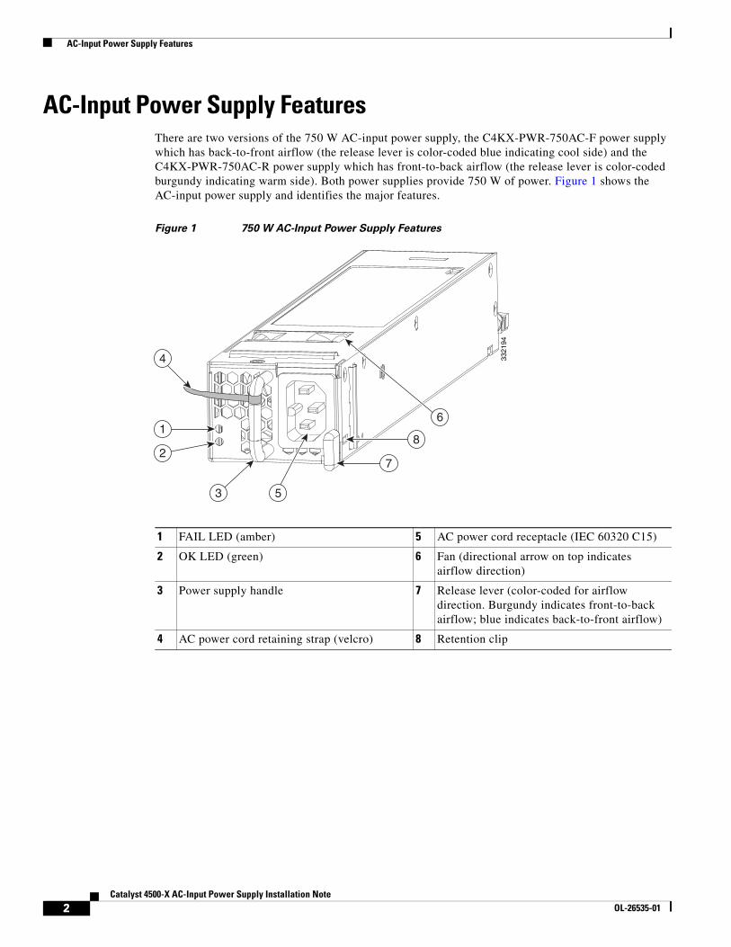
AC-Input Power Supply FeaturesThere are two versions of the 750 W AC-input power supply, the C4KX-PWR-750AC-F power supply which has back-to-front airflow (the release lever is color-coded blue indicating cool side) and the C4KX-PWR-750AC-R power supply which has front-to-back airflow (the release lever is color-coded burgundy indicating warm side). Both power supplies provide 750 W of power. Figure 1 shows the AC-input power supply and identifies the major features.
Figure 1 750 W AC-Input Power Supply Features
1 FAIL LED (amber) 5 AC power cord receptacle (IEC 60320 C15)
2 OK LED (green) 6 Fan (directional arrow on top indicates airflow direction)
3 Power supply handle 7 Release lever (color-coded for airflow direction. Burgundy indicates front-to-back airflow; blue indicates back-to-front airflow)
4 AC power cord retaining strap (velcro) 8 Retention clip
7
8
61
4
2
3 533
2194
2Catalyst 4500-X AC-Input Power Supply Installation Note
OL-26535-01
Safety
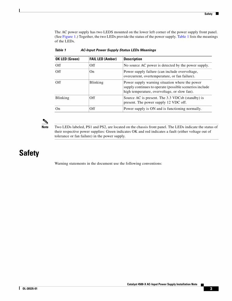
The AC power supply has two LEDS mounted on the lower left corner of the power supply front panel. (See Figure 1.) Together, the two LEDs provide the status of the power supply. Table 1 lists the meanings of the LEDs.
Note Two LEDs labeled, PS1 and PS2, are located on the chassis front panel. The LEDs indicate the status of their respective power supplies: Green indicates OK and red indicates a fault (either voltage out of tolerance or fan failure) in the power supply.
SafetyWarning statements in the document use the following conventions:
Table 1 AC-Input Power Supply Status LEDs Meanings
OK LED (Green) FAIL LED (Amber) Description
Off Off No source AC power is detected by the power supply.
Off On Power supply failure (can include overvoltage, overcurrent, overtemperature, or fan failure).
Off Blinking Power supply warning situation where the power supply continues to operate (possible scenerios include high temperature, overvoltage, or slow fan).
Blinking Off Source AC is present. The 3.3 VDCsb (standby) is present. The power supply 12 VDC off.
On Off Power supply is ON and is functioning normally.
3Catalyst 4500-X AC-Input Power Supply Installation Note
OL-26535-01
Safety
Statement 1071—Warning Definition
Warning IMPORTANT SAFETY INSTRUCTIONS
This warning symbol means danger. You are in a situation that could cause bodily injury. Before you work on any equipment, be aware of the hazards involved with electrical circuitry and be familiar with standard practices for preventing accidents. Use the statement number provided at the end of each warning to locate its translation in the translated safety warnings that accompanied this device.
SAVE THESE INSTRUCTIONS
Waarschuwing BELANGRIJKE VEILIGHEIDSINSTRUCTIES
Dit waarschuwingssymbool betekent gevaar. U verkeert in een situatie die lichamelijk letsel kan veroorzaken. Voordat u aan enige apparatuur gaat werken, dient u zich bewust te zijn van de bij elektrische schakelingen betrokken risico's en dient u op de hoogte te zijn van de standaard praktijken om ongelukken te voorkomen. Gebruik het nummer van de verklaring onderaan de waarschuwing als u een vertaling van de waarschuwing die bij het apparaat wordt geleverd, wilt raadplegen.
BEWAAR DEZE INSTRUCTIES
Varoitus TÄRKEITÄ TURVALLISUUSOHJEITA
Tämä varoitusmerkki merkitsee vaaraa. Tilanne voi aiheuttaa ruumiillisia vammoja. Ennen kuin käsittelet laitteistoa, huomioi sähköpiirien käsittelemiseen liittyvät riskit ja tutustu onnettomuuksien yleisiin ehkäisytapoihin. Turvallisuusvaroitusten käännökset löytyvät laitteen mukana toimitettujen käännettyjen turvallisuusvaroitusten joukosta varoitusten lopussa näkyvien lausuntonumeroiden avulla.
SÄILYTÄ NÄMÄ OHJEET
Attention IMPORTANTES INFORMATIONS DE SÉCURITÉ
Ce symbole d'avertissement indique un danger. Vous vous trouvez dans une situation pouvant entraîner des blessures ou des dommages corporels. Avant de travailler sur un équipement, soyez conscient des dangers liés aux circuits électriques et familiarisez-vous avec les procédures couramment utilisées pour éviter les accidents. Pour prendre connaissance des traductions des avertissements figurant dans les consignes de sécurité traduites qui accompagnent cet appareil, référez-vous au numéro de l'instruction situé à la fin de chaque avertissement.
CONSERVEZ CES INFORMATIONS
4Catalyst 4500-X AC-Input Power Supply Installation Note
OL-26535-01
Safety
Warnung WICHTIGE SICHERHEITSHINWEISE
Dieses Warnsymbol bedeutet Gefahr. Sie befinden sich in einer Situation, die zu Verletzungen führen kann. Machen Sie sich vor der Arbeit mit Geräten mit den Gefahren elektrischer Schaltungen und den üblichen Verfahren zur Vorbeugung vor Unfällen vertraut. Suchen Sie mit der am Ende jeder Warnung angegebenen Anweisungsnummer nach der jeweiligen Übersetzung in den übersetzten Sicherheitshinweisen, die zusammen mit diesem Gerät ausgeliefert wurden.
BEWAHREN SIE DIESE HINWEISE GUT AUF.
Avvertenza IMPORTANTI ISTRUZIONI SULLA SICUREZZA
Questo simbolo di avvertenza indica un pericolo. La situazione potrebbe causare infortuni alle persone. Prima di intervenire su qualsiasi apparecchiatura, occorre essere al corrente dei pericoli relativi ai circuiti elettrici e conoscere le procedure standard per la prevenzione di incidenti. Utilizzare il numero di istruzione presente alla fine di ciascuna avvertenza per individuare le traduzioni delle avvertenze riportate in questo documento.
CONSERVARE QUESTE ISTRUZIONI
Advarsel VIKTIGE SIKKERHETSINSTRUKSJONER
Dette advarselssymbolet betyr fare. Du er i en situasjon som kan føre til skade på person. Før du begynner å arbeide med noe av utstyret, må du være oppmerksom på farene forbundet med elektriske kretser, og kjenne til standardprosedyrer for å forhindre ulykker. Bruk nummeret i slutten av hver advarsel for å finne oversettelsen i de oversatte sikkerhetsadvarslene som fulgte med denne enheten.
TA VARE PÅ DISSE INSTRUKSJONENE
Aviso INSTRUÇÕES IMPORTANTES DE SEGURANÇA
Este símbolo de aviso significa perigo. Você está em uma situação que poderá ser causadora de lesões corporais. Antes de iniciar a utilização de qualquer equipamento, tenha conhecimento dos perigos envolvidos no manuseio de circuitos elétricos e familiarize-se com as práticas habituais de prevenção de acidentes. Utilize o número da instrução fornecido ao final de cada aviso para localizar sua tradução nos avisos de segurança traduzidos que acompanham este dispositivo.
GUARDE ESTAS INSTRUÇÕES
¡Advertencia! INSTRUCCIONES IMPORTANTES DE SEGURIDAD
Este símbolo de aviso indica peligro. Existe riesgo para su integridad física. Antes de manipular cualquier equipo, considere los riesgos de la corriente eléctrica y familiarícese con los procedimientos estándar de prevención de accidentes. Al final de cada advertencia encontrará el número que le ayudará a encontrar el texto traducido en el apartado de traducciones que acompaña a este dispositivo.
GUARDE ESTAS INSTRUCCIONES
5Catalyst 4500-X AC-Input Power Supply Installation Note
OL-26535-01
Safety
Varning! VIKTIGA SÄKERHETSANVISNINGAR
Denna varningssignal signalerar fara. Du befinner dig i en situation som kan leda till personskada. Innan du utför arbete på någon utrustning måste du vara medveten om farorna med elkretsar och känna till vanliga förfaranden för att förebygga olyckor. Använd det nummer som finns i slutet av varje varning för att hitta dess översättning i de översatta säkerhetsvarningar som medföljer denna anordning.
SPARA DESSA ANVISNINGAR
6Catalyst 4500-X AC-Input Power Supply Installation Note
OL-26535-01
Safety
Aviso INSTRUÇÕES IMPORTANTES DE SEGURANÇA
Este símbolo de aviso significa perigo. Você se encontra em uma situação em que há risco de lesões corporais. Antes de trabalhar com qualquer equipamento, esteja ciente dos riscos que envolvem os circuitos elétricos e familiarize-se com as práticas padrão de prevenção de acidentes. Use o número da declaração fornecido ao final de cada aviso para localizar sua tradução nos avisos de segurança traduzidos que acompanham o dispositivo.
GUARDE ESTAS INSTRUÇÕES
Advarsel VIGTIGE SIKKERHEDSANVISNINGER
Dette advarselssymbol betyder fare. Du befinder dig i en situation med risiko for legemesbeskadigelse. Før du begynder arbejde på udstyr, skal du være opmærksom på de involverede risici, der er ved elektriske kredsløb, og du skal sætte dig ind i standardprocedurer til undgåelse af ulykker. Brug erklæringsnummeret efter hver advarsel for at finde oversættelsen i de oversatte advarsler, der fulgte med denne enhed.
GEM DISSE ANVISNINGER
7Catalyst 4500-X AC-Input Power Supply Installation Note
OL-26535-01
Safety
8Catalyst 4500-X AC-Input Power Supply Installation Note
OL-26535-01
Tools Required
Tools RequiredNo specific tools are required to install or remove the AC-input power supply.
Installing the Power SupplyTo install the AC-input power supply, follow these steps:
Step 1 Remove the power supply from the shipping packaging and discard the packaging.
Step 2 Verify that the new power supply has the correct airflow direction (front-to-back or back-to-front) for your situation. The power supply release lever (see Figure 1), is color-coded blue for back-to-front airflow or burgundy for front-to-back airflow.
9Catalyst 4500-X AC-Input Power Supply Installation Note
OL-26535-01
Installing the Power Supply
Note The chassis determines which airflow direction is correct by polling all of the fan assemblies and the power supplies. The airflow direction for all of the devices must be the same. If the airflow direction of the replacement power supply or the redundant power supply does not match the fan assemblies airflow direction, the system software shuts down the power supply and generates a power supply mismatch error message on the console.
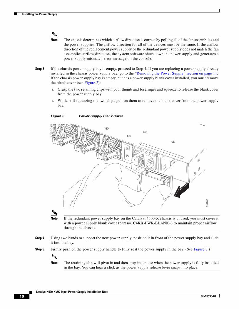
Step 3 If the chassis power supply bay is empty, proceed to Step 4. If you are replacing a power supply already installed in the chassis power supply bay, go to the “Removing the Power Supply” section on page 11. If the chassis power supply bay is empty, but has a power supply blank cover installed, you must remove the blank cover (see Figure 2):
a. Grasp the two retaining clips with your thumb and forefinger and squeeze to release the blank cover from the power supply bay.
b. While still squeezing the two clips, pull on them to remove the blank cover from the power supply bay.
Figure 2 Power Supply Blank Cover
Note If the redundant power supply bay on the Catalyst 4500-X chassis is unused, you must cover it with a power supply blank cover (part no. C4KX-PWR-BLANK=) to maintain proper airflow through the chassis.
Step 4 Using two hands to support the new power supply, position it in front of the power supply bay and slide it into the bay.
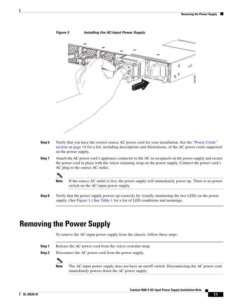
Step 5 Firmly push on the power supply handle to fully seat the power supply in the bay. (See Figure 3.)
Note The retaining clip will pivot in and then snap into place when the power supply is fully installed in the bay. You can hear a click as the power supply release lever snaps into place.
3322
07
10Catalyst 4500-X AC-Input Power Supply Installation Note
OL-26535-01
Removing the Power Supply
Figure 3 Installing the AC-Input Power Supply
Step 6 Verify that you have the correct source AC power cord for your installation. See the “Power Cords” section on page 14 for a list, including descriptions and illustrations, of the AC power cords supported on the power supply.
Step 7 Attach the AC power cord’s appliance connector to the AC-in receptacle on the power supply and secure the power cord in place with the velcro retaining strap on the power supply. Connect the power cord’s AC plug to the source AC outlet.
Note If the source AC outlet is live, the power supply will immediately power up. There is no power switch on the AC-input power supply.
Step 8 Verify that the power supply powers up correctly by visually monitoring the two LEDs on the power supply. (See Figure 1.) See Table 1 for a list of LED conditions and meanings.
Removing the Power SupplyTo remove the AC-input power supply from the chassis, follow these steps:
Step 1 Release the AC power cord from the velcro restraint strap.
Step 2 Disconnect the AC power cord from the power supply.
Note The AC-input power supply does not have an on/off switch. Disconnecting the AC power cord immediately powers down the AC power supply.
3322
08
11Catalyst 4500-X AC-Input Power Supply Installation Note
OL-26535-01
Removing the Power Supply
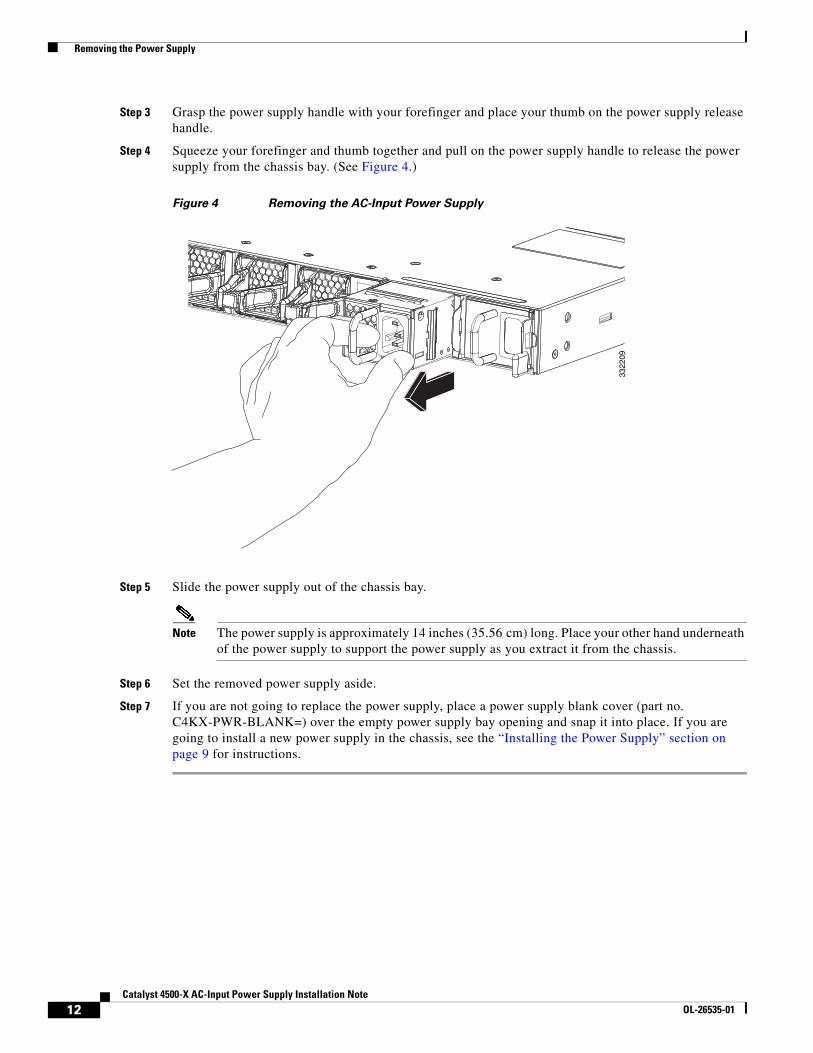
Step 3 Grasp the power supply handle with your forefinger and place your thumb on the power supply release handle.
Step 4 Squeeze your forefinger and thumb together and pull on the power supply handle to release the power supply from the chassis bay. (See Figure 4.)
Figure 4 Removing the AC-Input Power Supply
Step 5 Slide the power supply out of the chassis bay.
Note The power supply is approximately 14 inches (35.56 cm) long. Place your other hand underneath of the power supply to support the power supply as you extract it from the chassis.
Step 6 Set the removed power supply aside.
Step 7 If you are not going to replace the power supply, place a power supply blank cover (part no. C4KX-PWR-BLANK=) over the empty power supply bay opening and snap it into place. If you are going to install a new power supply in the chassis, see the “Installing the Power Supply” section on page 9 for instructions.
3322
09
12Catalyst 4500-X AC-Input Power Supply Installation Note
OL-26535-01
Power Supply Specifications
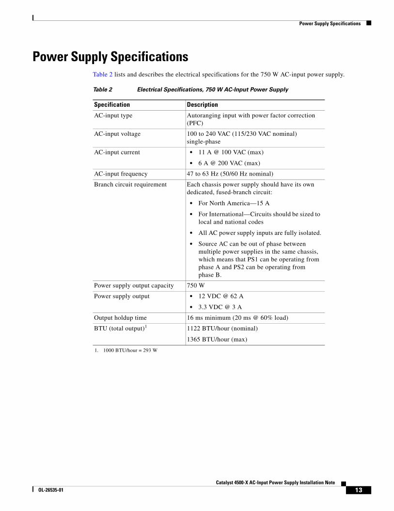
Power Supply SpecificationsTable 2 lists and describes the electrical specifications for the 750 W AC-input power supply.
Table 2 Electrical Specifications, 750 W AC-Input Power Supply
Specification Description
AC-input type Autoranging input with power factor correction (PFC)
AC-input voltage 100 to 240 VAC (115/230 VAC nominal) single-phase
AC-input current • 11 A @ 100 VAC (max)
• 6 A @ 200 VAC (max)
AC-input frequency 47 to 63 Hz (50/60 Hz nominal)
Branch circuit requirement Each chassis power supply should have its own dedicated, fused-branch circuit:
• For North America—15 A
• For International—Circuits should be sized to local and national codes
• All AC power supply inputs are fully isolated.
• Source AC can be out of phase between multiple power supplies in the same chassis, which means that PS1 can be operating from phase A and PS2 can be operating from phase B.
Power supply output capacity 750 W
Power supply output • 12 VDC @ 62 A
• 3.3 VDC @ 3 A
Output holdup time 16 ms minimum (20 ms @ 60% load)
BTU (total output)1
1. 1000 BTU/hour = 293 W
1122 BTU/hour (nominal)
1365 BTU/hour (max)
13Catalyst 4500-X AC-Input Power Supply Installation Note
OL-26535-01
Power Cords
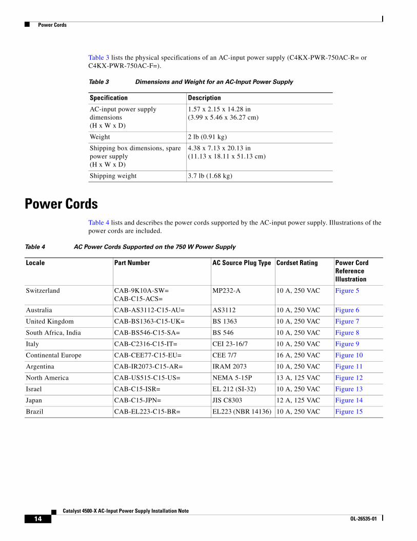
Table 3 lists the physical specifications of an AC-input power supply (C4KX-PWR-750AC-R= or C4KX-PWR-750AC-F=).
Power CordsTable 4 lists and describes the power cords supported by the AC-input power supply. Illustrations of the power cords are included.
Table 3 Dimensions and Weight for an AC-Input Power Supply
Specification Description
AC-input power supply dimensions(H x W x D)
1.57 x 2.15 x 14.28 in (3.99 x 5.46 x 36.27 cm)
Weight 2 lb (0.91 kg)
Shipping box dimensions, spare power supply(H x W x D)
4.38 x 7.13 x 20.13 in (11.13 x 18.11 x 51.13 cm)
Shipping weight 3.7 lb (1.68 kg)
Table 4 AC Power Cords Supported on the 750 W Power Supply
Locale Part Number AC Source Plug Type Cordset Rating Power Cord Reference Illustration
Switzerland CAB-9K10A-SW=CAB-C15-ACS=
MP232-A 10 A, 250 VAC Figure 5
Australia CAB-AS3112-C15-AU= AS3112 10 A, 250 VAC Figure 6
United Kingdom CAB-BS1363-C15-UK= BS 1363 10 A, 250 VAC Figure 7
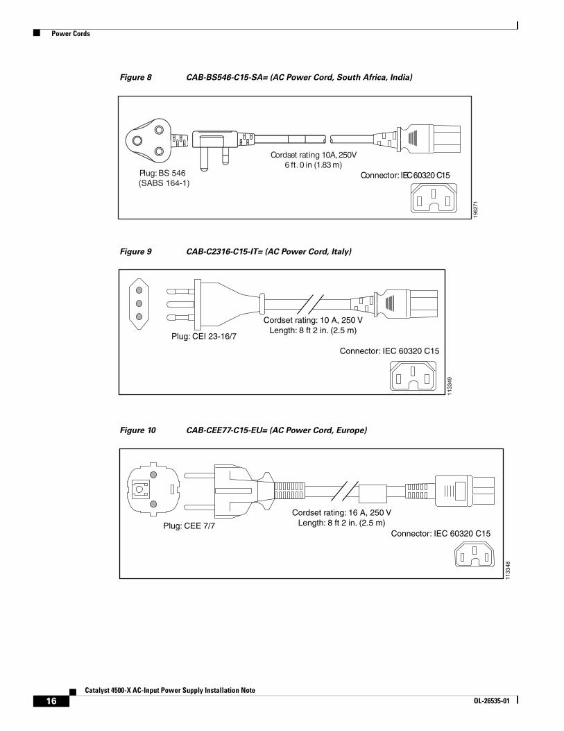
South Africa, India CAB-BS546-C15-SA= BS 546 10 A, 250 VAC Figure 8
Italy CAB-C2316-C15-IT= CEI 23-16/7 10 A, 250 VAC Figure 9
Continental Europe CAB-CEE77-C15-EU= CEE 7/7 16 A, 250 VAC Figure 10
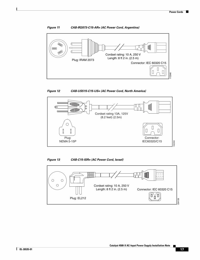
Argentina CAB-IR2073-C15-AR= IRAM 2073 10 A, 250 VAC Figure 11
North America CAB-US515-C15-US= NEMA 5-15P 13 A, 125 VAC Figure 12
Israel CAB-C15-ISR= EL 212 (SI-32) 10 A, 250 VAC Figure 13
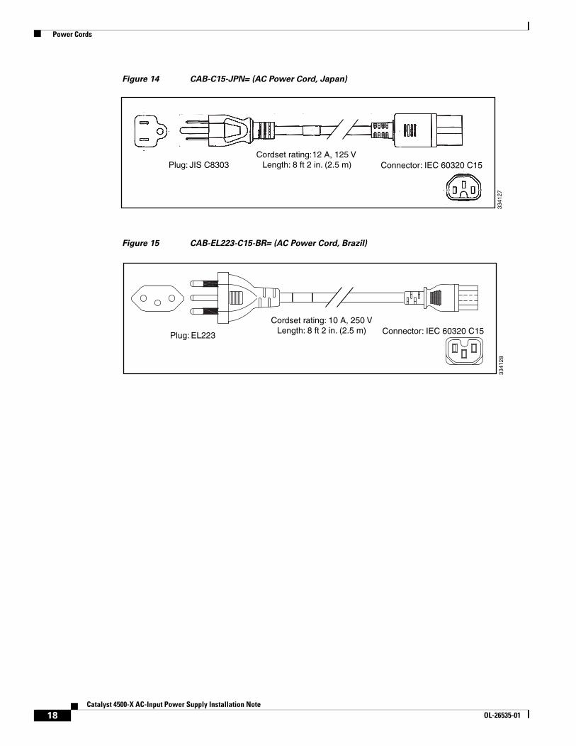
Japan CAB-C15-JPN= JIS C8303 12 A, 125 VAC Figure 14
Brazil CAB-EL223-C15-BR= EL223 (NBR 14136) 10 A, 250 VAC Figure 15
14Catalyst 4500-X AC-Input Power Supply Installation Note
OL-26535-01
Power Cords
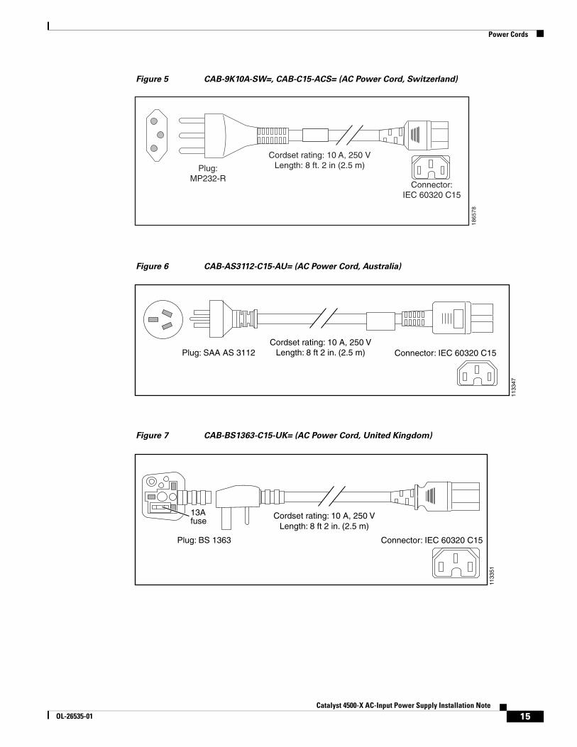
Figure 5 CAB-9K10A-SW=, CAB-C15-ACS= (AC Power Cord, Switzerland)
Figure 6 CAB-AS3112-C15-AU= (AC Power Cord, Australia)
Figure 7 CAB-BS1363-C15-UK= (AC Power Cord, United Kingdom)
Plug:MP232-R
Cordset rating: 10 A, 250 VLength: 8 ft. 2 in (2.5 m)
1865
78
Connector:IEC 60320 C15
Connector: IEC 60320 C15Cordset rating: 10 A, 250 V
Length: 8 ft 2 in. (2.5 m)Plug: SAA AS 3112
1133
47Cordset rating: 10 A, 250 V
Length: 8 ft 2 in. (2.5 m)
1133
51
Connector: IEC 60320 C15Plug: BS 1363
13Afuse
15Catalyst 4500-X AC-Input Power Supply Installation Note
OL-26535-01
Power Cords
Figure 8 CAB-BS546-C15-SA= (AC Power Cord, South Africa, India)
Figure 9 CAB-C2316-C15-IT= (AC Power Cord, Italy)
Figure 10 CAB-CEE77-C15-EU= (AC Power Cord, Europe)
Cordset rating 10A, 250V6 ft. 0 in (1.83 m)
Plug: BS 546(SABS 164-1)
1962
71
Connector: IEC 60320 C15
Plug: CEI 23-16/7
Cordset rating: 10 A, 250 VLength: 8 ft 2 in. (2.5 m)
1133
49
Connector: IEC 60320 C15
Connector: IEC 60320 C15
Cordset rating: 16 A, 250 VLength: 8 ft 2 in. (2.5 m)Plug: CEE 7/7
1133
48
16Catalyst 4500-X AC-Input Power Supply Installation Note
OL-26535-01
Power Cords
Figure 11 CAB-IR2073-C15-AR= (AC Power Cord, Argentina)
Figure 12 CAB-US515-C15-US= (AC Power Cord, North America)
Figure 13 CAB-C15-ISR= (AC Power Cord, Israel)
Plug: IRAM 2073
Cordset rating: 10 A, 250 VLength: 8 ft 2 in. (2.5 m)
1133
46
Connector: IEC 60320 C15
Connector:IEC60320/C15
Cordset rating 13A, 125V(8.2 feet) (2.5m)
Plug:NEMA 5-15P
1922
60
Connector: IEC 60320 C15Cordset rating: 10 A, 250 V
Length: 8 ft 2 in. (2.5 m)
Plug: EL212
3341
26
17Catalyst 4500-X AC-Input Power Supply Installation Note
OL-26535-01
Power Cords
Figure 14 CAB-C15-JPN= (AC Power Cord, Japan)
Figure 15 CAB-EL223-C15-BR= (AC Power Cord, Brazil)
Connector: IEC 60320 C15Cordset rating:12 A, 125 V
Length: 8 ft 2 in. (2.5 m)Plug: JIS C8303
3341
27
Connector: IEC 60320 C15Cordset rating: 10 A, 250 V
Length: 8 ft 2 in. (2.5 m)Plug: EL223
3341
28
18Catalyst 4500-X AC-Input Power Supply Installation Note
OL-26535-01
Related Documentation
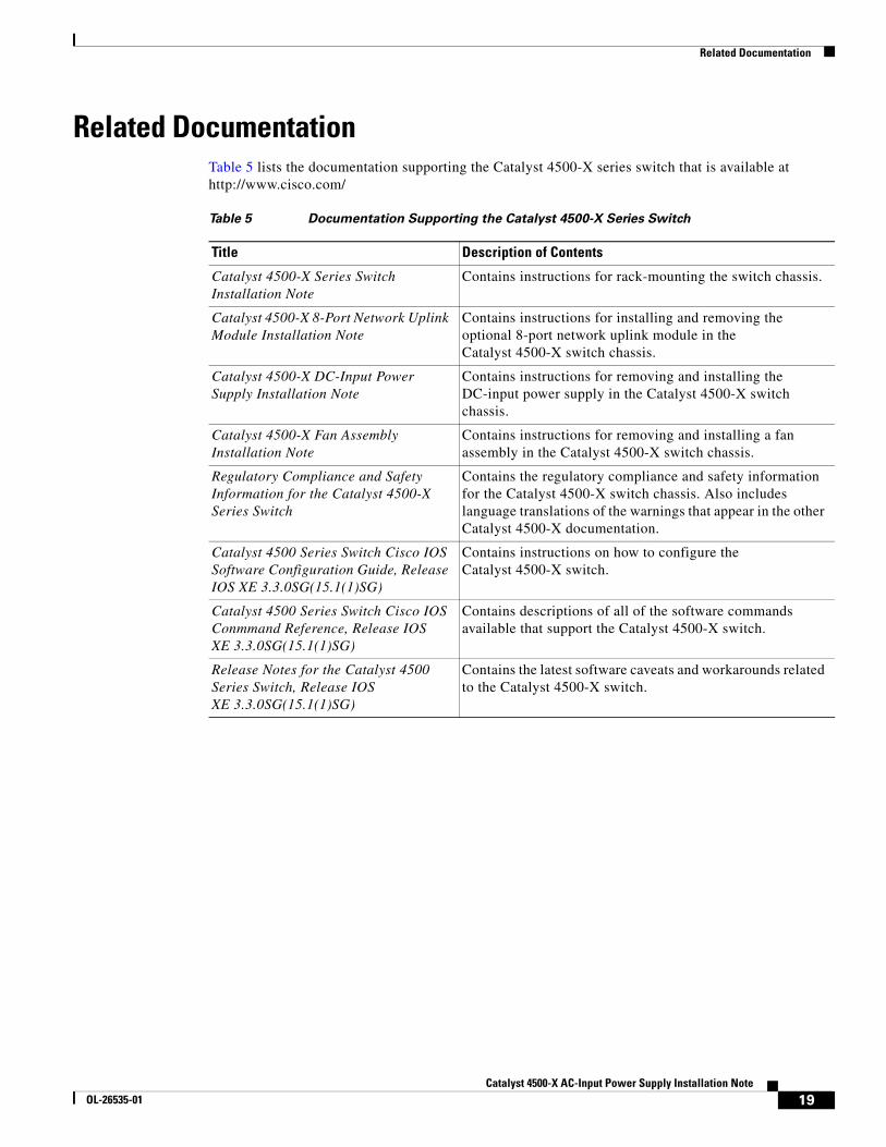
Related DocumentationTable 5 lists the documentation supporting the Catalyst 4500-X series switch that is available at http://www.cisco.com/
Table 5 Documentation Supporting the Catalyst 4500-X Series Switch
Title Description of Contents
Catalyst 4500-X Series Switch Installation Note
Contains instructions for rack-mounting the switch chassis.
Catalyst 4500-X 8-Port Network Uplink Module Installation Note
Contains instructions for installing and removing the optional 8-port network uplink module in the Catalyst 4500-X switch chassis.
Catalyst 4500-X DC-Input Power Supply Installation Note
Contains instructions for removing and installing the DC-input power supply in the Catalyst 4500-X switch chassis.
Catalyst 4500-X Fan Assembly Installation Note
Contains instructions for removing and installing a fan assembly in the Catalyst 4500-X switch chassis.
Regulatory Compliance and Safety Information for the Catalyst 4500-X Series Switch
Contains the regulatory compliance and safety information for the Catalyst 4500-X switch chassis. Also includes language translations of the warnings that appear in the other Catalyst 4500-X documentation.
Catalyst 4500 Series Switch Cisco IOS Software Configuration Guide, Release IOS XE 3.3.0SG(15.1(1)SG)
Contains instructions on how to configure the Catalyst 4500-X switch.
Catalyst 4500 Series Switch Cisco IOS Conmmand Reference, Release IOS XE 3.3.0SG(15.1(1)SG)
Contains descriptions of all of the software commands available that support the Catalyst 4500-X switch.
Release Notes for the Catalyst 4500 Series Switch, Release IOS XE 3.3.0SG(15.1(1)SG)
Contains the latest software caveats and workarounds related to the Catalyst 4500-X switch.
19Catalyst 4500-X AC-Input Power Supply Installation Note
OL-26535-01
Obtaining Documentation and Submitting a Service Request
Obtaining Documentation and Submitting a Service RequestFor information on obtaining documentation, submitting a service request, and gathering additional information, see the monthly What’s New in Cisco Product Documentation, which also lists all new and revised Cisco technical documentation, at:
http://www.cisco.com/en/US/docs/general/whatsnew/whatsnew.html
Subscribe to the What’s New in Cisco Product Documentation as an RSS feed and set content to be delivered directly to your desktop using a reader application. The RSS feeds are a free service. Cisco currently supports RSS Version 2.0.
This document is to be used in conjunction with the documents listed in the “Related Documentation” section.
Cisco and the Cisco logo are trademarks or registered trademarks of Cisco and/or its affiliates in the U.S. and other countries. To view a list of Cisco trademarks, go to this URL: www.cisco.com/go/trademarks. Third-party trademarks mentioned are the property of their respective owners. The use of the word partner does not imply a partnership relationship between Cisco and any other company. (1110R)
Any Internet Protocol (IP) addresses and phone numbers used in this document are not intended to be actual addresses and phone numbers. Any examples, command display output, network topology diagrams, and other figures included in the document are shown for illustrative purposes only. Any use of actual IP addresses or phone numbers in illustrative content is unintentional and coincidental.
© 2012 Cisco Systems, Inc. All rights reserved.
20Catalyst 4500-X AC-Input Power Supply Installation Note
OL-26535-01