Embed Size (px)
Citation preview
Common CatOS Error Messages on Catalyst4500/4000 Series Switches
Document ID: 30003
Contents
Introduction Prerequisites Requirements Components Used Conventions Error Messages on Catalyst 4500/4000 Series Switches
%C4K_HWPORTMAN−4−BLOCKEDTXQUEUE:Blocked transmit queue HwTxQId[dec]on [char],count=[dec]%CDP−4−NVLANMISMATCH: Native vlan mismatch detected on port [dec]/[dec]DTP−1−ILGLCFG: Illegal config (on, isl−−on,dot1q) on Port [mod/port] %IP−3−UDP_SOCKOVFL:UDP socket overflow %IP−3−UDP_BADCKSUM:UDP bad checksum %KERNEL−5−UNALIGNACCESS:Alignment correction made %MCAST−4−RX_JNRANGE:IGMP: Rcvd Report in the range MGMT−5−LOGIN_FAIL:User failed to log in from Console %PAGP−5−PORTFROMSTP / %PAGP−5−PORTTOSTP %SPANTREE−3−PORTDEL_FAILNOTFOUND %SYS−3−P2_ERROR: 1/Unknown module%SYS−3−P2_ERROR: 1/Have run out of vbufs (internal buffers) %SYS−3−P2_ERROR: Host xx:xx:xx:xx:xx:xx is flapping between ports%SYS−4−P2_WARN: 1/Blocked queue (tx) on port [char] %SYS−4−P2_WARN: 1/Filtering Ethernet MAC address of value zero %SYS−4−P2_WARN: 1/Invalid crc, dropped packet, count = xx %SYS−4−P2_WARN: 1/Invalid traffic from multicast source address%SYS−4−P2_WARN: 1/Astro(mod/port) %SYS−4−P2_WARN: 1/Tag 0convert_post_SAC_CiscoMIB:Nvram block [#] unconvertible Global checksum failed error Related Information
Introduction
This document provides a brief explanation of common system log (syslog) and error messages that you seeon Cisco Catalyst 4500/4000 series switches that run Catalyst OS (CatOS) software.
If you do not find the details for a specific error message in this document, use the Error Message Decoder (registered customers only) tool. This tool provides the meaning of error messages that Cisco IOS® Softwareand CatOS software generate.
Note: The exact format of the syslog and error messages that this document describes can vary. The variationdepends on the software release that runs on the switch Supervisor Engine.
Note: This is the recommended minimum logging configuration on the Catalyst 4500/4000 series switches:
Set the date and time on the switch, or configure the switch to use Network Time Protocol (NTP) inorder to obtain the date and time from an NTP server.
Note: Issue the set time command in order to set the date and time on the switch.
•
Ensure that logging and logging time stamps are enabled, which is the default.• Configure the switch to log to a syslog server, if possible.•
The error messages in this document can occur on the Catalyst 4500/4000 series switches and on derivativesof these switches, such as Catalyst 2948G, 2980G, and 4912G switches.
Prerequisites
Requirements
There are no specific requirements for this document.
Components Used
This document is not restricted to specific software or hardware versions.
Conventions
Refer to Cisco Technical Tips Conventions for more information on document conventions.
Error Messages on Catalyst 4500/4000 Series Switches
%C4K_HWPORTMAN−4−BLOCKEDTXQUEUE:Blocked transmit queueHwTxQId[dec]on [char], count=[dec]
Problem
The switch generates %C4K_HWPORTMAN−4−BLOCKEDTXQUEUE:Blocked transmit queueHwTxQId[dec]on[char], count=[dec] errors.
Description
This rate−limited message indicates that a transmit queue on a port is blocked for reasons other than�paused�. In other words, the traffic on that port is being limited and blocked. You see the blocked transmitqueue messages if the Supervisor Engine is not able to send packets to the line card because of the receptionof a busy bit from the line card. Bad hardware or a speed/duplex mismatch can cause this problem. Theworkaround is to configure both sides of the link to autonegotiate for speed and duplex. Issue the shut/noshut command in order to recover the port. If the problem persists, move the connected device to another portand see if the problem happens there. As a final measure to unblock the transmit (Tx) queue, issue thehw−module reset command in order to reboot the switch or reset the line card.
%CDP−4−NVLANMISMATCH: Native vlan mismatch detected on port[dec]/[dec]
Problem
The switch generates frequent %CDP−4−NVLANMISMATCH syslog messages.
Description
This example shows the console output that you see when this error message occurs on the switch:
%CDP−4−NVLANMISMATCH:Native vlan mismatch detected on port 4/1
The switch generates this message whenever the switch port is physically connected to another switch orrouter. The switch generates this message because the configured native VLAN on the port is different thanthe native VLAN that is set on the connecting switch or router port.
A trunk port that you configure with IEEE 802.1Q tagging can receive both tagged and untagged traffic. Bydefault, the switch forwards untagged traffic with the native VLAN that is configured for the port. If a packethas the same VLAN ID as the outgoing port native VLAN ID, the packet is transmitted untagged. If theVLAN IDs are not the same, the switch transmits the packet with a tag.
Ensure that the native VLAN for an 802.1Q trunk is the same on both ends of the trunk link. If the nativeVLAN on one end of the trunk is different than the native VLAN on the other end, the traffic of the nativeVLANs on both sides cannot be transmitted correctly on the trunk. This failure to transmit correctly can implysome connectivity issues in your network.
In order to verify the native VLAN that is configured on your switch, issue the show trunk mod/portcommand. In this command, mod/port is the trunk port. Here is sample output from the command:
Console> (enable) show trunk 5/24
Port Mode Encapsulation Status Native vlan−−−−−−−− −−−−−−−−−−− −−−−−−−−−−−−− −−−−−−−−−−−− −−−−−−−−−−− 5/24 desirable dot1q not−trunking 1
Port Vlans allowed on trunk−−−−−−−− −−−−−−−−−−−−−−−−−−−−−−−−−−−−−−−−−−−−−−−−−−−−−−−−−−−−−−−−−−−−−−−−−−−−− 5/24 1−1005
Port Vlans allowed and active in management domain−−−−−−−− −−−−−−−−−−−−−−−−−−−−−−−−−−−−−−−−−−−−−−−−−−−−−−−−−−−−−−−−−−−−−−−−−−−−− 5/24 1
Port Vlans in spanning tree forwarding state and not pruned−−−−−−−− −−−−−−−−−−−−−−−−−−−−−−−−−−−−−−−−−−−−−−−−−−−−−−−−−−−−−−−−−−−−−−−−−−−−− 5/24
Console> (enable)
In order to change the native VLAN that is configured on the trunk port, issue the set vlan vlan−id mod/portcommand. In this command, mod/port is the trunk port.
DTP−1−ILGLCFG: Illegal config (on, isl−−on,dot1q) on Port [mod/port]
Problem
The switch generates DTP−1−ILGLCFG: Illegal config (on, isl−−on,dot1q) on Port[mod/port] errors.
Description
This message can occur if both sides of the trunk are set to on, but the encapsulation types (isl, dot1q)do not match. If the trunk modes are set to desirable, the trunk does not come up because of thismisconfiguration. In order to troubleshoot, check the output of the show trunk command on both ends.Ensure that the encapsulation types are identical.
%IP−3−UDP_SOCKOVFL:UDP socket overflow
Problem
The switch generates periodic %IP−3−UDP_SOCKOVFL:UDP socket overflow syslog messages.
Description
This example shows the console output that you see when this error occurs:
Note: The User Datagram Protocol (UDP) socket number that displays can vary or be consistently the same.
%IP−3−UDP_SOCKOVFL:UDP socket 2353 overflow%IP−3−UDP_SOCKOVFL:UDP socket 2353 overflow%IP−3−UDP_SOCKOVFL:UDP socket 2353 overflow%IP−3−UDP_SOCKOVFL:UDP socket 2353 overflow
The switch generates this syslog message when the buffer that is allocated for incoming packets on thespecified socket (UDP destination port) is full. The buffer is full because the rate of traffic that is destined forthat socket is too high. For example, this condition can occur when a network management station sends alarge number of Simple Network Management Protocol (SNMP) queries. When UDP overflow occurs, try toreduce the number of SNMP queries. Perform one of these actions:
Increase the polling interval on the network management station.• Reduce the number of MIB objects that are polled.•
In the example in this section, the switch received an excessive number of packets that were destined for theswitch IP address (or the broadcast address) with destination UDP socket 2353. Because the input buffer forthis socket on the switch is full, the switch generates a syslog message. Issue the show netstat udp commandin order to see the number of times that the switch reached the overflow condition.
These syslog messages indicate that one or more stations send a large amount of UDP traffic on the specifieddestination UDP ports to the switch. If the switch generates an excessive number of these messages, use anetwork analyzer in order to identify the source of the traffic and reduce the rate of traffic. Refer to CatalystSwitched Port Analyzer (SPAN) Configuration Example for more information.
Note: Do not worry about the no such port counter. This counter shows the number of UDP packets thatthe switch received that were destined for nonexistent ports.
%IP−3−UDP_BADCKSUM:UDP bad checksum
Problem
The switch generates periodic %IP−3−UDP_SOCKOVFL:UDP socket overflow syslog messages.
Description
This example shows the console output that you see when this error occurs:
Note: The UDP socket number that displays can vary or be consistently the same.
%IP−3−UDP_BADCKSUM:UDP bad checksum
The switch generates this syslog message when the switch detects a bad checksum on a UDP datagram, suchas SNMP packets. The UDP datagram header carries a checksum that the receiving network device checks inorder to determine if the datagram was corrupted during transit. If the received checksum does not match thechecksum value in the header, the datagram is dropped and an error message is logged. Issue the show netstatudp command in order to see the number of times that the switch detected an erroneous checksum datagram.
6500−b (enable) show netstat udp
udp:0 incomplete headers0 bad data length fields0 bad checksums0 socket overflows110483 no such ports
This message is informational only. A network device that sends bad packets to the switch causes thismessage. Use a network analyzer in order to identify the source of the traffic. Refer to Catalyst Switched PortAnalyzer (SPAN) Configuration Example for more information.
Note: Do not worry about the no such port counter. This counter shows the number of UDP packets thatthe switch received that were destined for nonexistent ports.
%KERNEL−5−UNALIGNACCESS:Alignment correction made
Problem
The switch generates periodic %KERNEL−5−UNALIGNACCESS:Alignment correction madesyslog messages.
Description
This example shows the syslog output that you see when this error occurs:
%KERNEL−5−UNALIGNACCESS:Alignment correction made at 0x80056B3C reading 0x81B82F36
These syslog messages indicate that the switch CPU detected and corrected an alignment error when theswitch attempted to access data in DRAM. These messages are informational only. The messages do notindicate a problem with the switch and do not affect system performance.
In some cases, you see an excessive number of these messages. For example, these messages can flood yoursyslog server log file or your switch console. If you receive an excess of the messages, consider an upgrade ofthe switch software to the latest maintenance release for your software release train. Or issue the set logginglevel kernel 4 default command in order to modify the logging level for the Kernel facility to 4 or lower.
If you upgrade to the latest maintenance release but still receive these syslog messages, create a servicerequest (registered customers only) with Cisco Technical Support.
%MCAST−4−RX_JNRANGE:IGMP: Rcvd Report in the range
Problem
A switch that has Internet Group Management Protocol (IGMP) snooping enabled displays the%MCAST−4−RX_JNRANGE:IGMP: Rcvd Report in the range 01−00−5e−00−00−xx errormessage.
Description
This example shows the syslog output that you see when this error occurs:
%MCAST−4−RX_JNRANGE:IGMP: Rcvd Report in the range 01−00−5e−00−00−xx
The Rcvd Report in the range syslog message is informational only. The switch generates thismessage when the switch receives IGMP report packets with a multicast MAC address that starts with01−00−5e−00−00−xx. This Layer 2 (L2) range of addresses is equivalent to a Layer 3 (L3) multicast addressrange between 224.0.0.0 and 224.0.0.255. These addresses are reserved for the use of routing protocols andother low−level topology discovery or maintenance protocols. Examples of these protocols include gatewaydiscovery and group membership reporting.
Use a packet capture tool, such as a sniffer, and filter on IGMP messages in order to troubleshoot thisproblem. In addition, you can use the Catalyst SPAN function in order to copy packets from a port that yoususpect receives these messages from a network device. In order to suppress these messages, issue the setlogging level mcast 2 default command. This command changes the logging level of multicast messages to 2.
Use the ports that the show multicast router command shows and any uplinks to the core of the network asthe SPAN source ports. If these ports are trunk ports, also configure the SPAN destination port as a trunk port.Issue the show trunk command in order to verify that the ports are trunk ports.
MGMT−5−LOGIN_FAIL:User failed to log in from Console
Problem
The switch generates MGMT−5−LOGIN_FAIL:User failed to log in from Console errors.
Description
This message can indicate a problem with the terminal server that is connected to the console port of theswitch. When the switch console is connected to an async line of a terminal server and you perform a softreset on the switch, garbage (random text) streams across the screen for several minutes. If TACACS isenabled on the switch, several minutes can turn into several days because TACACS buffers and processes thegarbage piece by piece. The workaround is to issue the no exec command on the async line to which theswitch connects.
Note: Even after you issue the no exec command, the messages continue until the buffer is clear.
Note: If you receive the error message %MGMT−5−LOGIN_FAIL:User failed to log viaTelnet − max attempt reached, try to limit the number of users that are allowed to Telnet to theswitch.
%PAGP−5−PORTFROMSTP / %PAGP−5−PORTTOSTP
Problem
The switch generates frequent %PAGP−5−PORTFROMSTP and %PAGP−5−PORTTOSTP syslog messages.
Description
This example shows the console output that you see when the switch generates these syslog messages:
%PAGP−5−PORTFROMSTP:Port 3/3 left bridge port 3/3%PAGP−5−PORTTOSTP:Port 3/3 joined bridge port 3/3
The Port Aggregation Protocol (PAgP) logging facility reports events that involve PAgP. You use PAgP tonegotiate EtherChannel links between switches. The switch generates the %PAGP−5−PORTFROMSTP syslogmessage at the loss of a link on a switch port. The switch generates the %PAGP−5−PORTTOSTP syslogmessage at the detection of a link on a switch port. These syslog messages are normal, informational messagesthat indicate the addition or removal of a port from the spanning tree.
Note: The enablement of channeling is not necessary for these messages to appear.
In the example in this section, the switch first lost the link on port 3/3, which removed the port from thespanning tree. Then, the switch again detected the link on the port, which added the port back into thespanning tree.
If you see these messages frequently for a particular port, the link is flapping, which means that the link isconstantly lost and regained. Investigate the cause. Typical causes of link flapping on a switch port include:
Speed/duplex mismatch• Faulty cable• Faulty network interface card (NIC) or other end station problem• Faulty switch port• Other misconfiguration•
If you want to suppress these syslog messages, issue the set logging level pagp 4 default command in orderto modify the logging level for the PAgP facility to 4 or lower. The default logging level for PAgP is 5.
%SPANTREE−3−PORTDEL_FAILNOTFOUND
Problem
The switch generates periodic %SPANTREE−3−PORTDEL_FAILNOTFOUND syslog messages.
Description
This example shows the syslog output that you see when this error occurs:
%SPANTREE−3−PORTDEL_FAILNOTFOUND:9/5 in vlan 10 not found (PAgP_Group_Rx)
These syslog messages indicate that the PAgP attempted to remove a port from the spanning tree for thespecified VLAN, but the port was not in the spanning tree data structure for that VLAN. Typically, anotherprocess, such as the Dynamic Trunking Protocol (DTP) has already removed the port from the spanning tree.
These messages typically accompany %PAGP−5−PORTFROMSTP messages. The messages are for debugpurposes. The messages do not indicate a problem with the switch and do not affect switching performance. Inaddition, these messages are not logged unless you have changed the default SPANTREE facility loggingconfiguration. The default logging level for SPANTREE is 2.
In some cases, you see an excessive number of these messages. For example, these messages can flood yourswitch console. If you receive an excess of the messages, consider an upgrade of the switch software to thelatest maintenance release for your software release train. Later software releases suppress these messages inmost cases.
%SYS−3−P2_ERROR: 1/Unknown module
Problem
The %SYS−3−P2_ERROR: 1/Unknown module error message is displayed when you install a newswitching module in a Catalyst 4500/4000 series switch.
Description
This example shows the console output that you see when this error occurs:
%SYS−3−P2_ERROR: 1/Unknown module (fru minor type 304) in slot 3
The %SYS−3−P2_ERROR: 1/Unknown module error occurs when the software image version thatcurrently runs on the Supervisor Engine does not support the hardware component that you have inserted.
In the example, an 18−port 1000BASE−X server switching module (WS−X4418) is inserted into a Catalyst4500/4000 switch that runs CatOS software release 4.4(1). The WS−X4418 module requires a minimumsoftware release of 4.5(1).
The workaround is to upgrade the Supervisor Engine software version to a software release that supports thehardware. Refer to Release Notes for Catalyst 4500 Series Switches for a list of the minimum softwareversions for each module.
%SYS−3−P2_ERROR: 1/Have run out of vbufs (internal buffers)
Problem
The switch generates %SYS−3−P2_ERROR: 1/Have run out of vbufs messages when multiplehosts are powered up at or around the same time.
Description
This example shows the console output that you see when the error occurs:
%SYS−3−P2_ERROR: 1/Have run out of vbufs(internal buffers)
The %SYS−3−P2_ERROR: 1/Have run out of vbufs(internal buffers) errors can occurwhen multiple hosts are powered up simultaneously. After the hosts are powered up, the errors no longerappear.
These errors do not cause any interruption to the Catalyst ability to switch traffic. The messages are of aninformational nature only.
%SYS−3−P2_ERROR: Host xx:xx:xx:xx:xx:xx is flapping between ports
Problem
The switch generates %SYS−3−P2_ERROR: Host xx:xx:xx:xx:xx:xx is flapping betweenports& messages, where xx:xx:xx:xx:xx:xx is a MAC address.
Description
This example shows the console output that you see when this error occurs:
%SYS−4−P2_WARN: 1/Host 00:50:0f:20:08:00 is flapping between port 1/2 and port 4/39
Use the steps and guidelines in this section in order to understand and troubleshoot the cause of this errormessage.
The message indicates that your Catalyst 4500/4000 switch has learned a MAC address that already exists inthe content−addressable memory (CAM) table, on a port other than the original one. This behavior repeatedlyoccurs over short periods of time, which means that there is address flapping between ports.
If the message appears for multiple MAC addresses, the behavior is not normal. This behavior indicates apossible network problem because the MAC addresses move quickly from one port to another port before thedefault aging time. The problem can be looping traffic on the network. Typical symptoms include:
High CPU utilization• Slow traffic throughout the network• High backplane utilization on the switch•
For information on how to identify and troubleshoot issues with spanning tree, refer to Spanning TreeProtocol Problems and Related Design Considerations.
If the error message appears for one or two MAC addresses, locate these MAC addresses in order todetermine the cause. Issue the show cam mac_addr command in order to identify from where these MACaddresses have been learned. In this command, mac_addr is the MAC address that the error reports asflapping.
After you determine between which ports this MAC address is flapping, track down the MAC address.Connect to the intermediate devices between your Catalyst 4500/4000 and the device that has the problemMAC address. Do this until you are able to identify the source and how this device connects to the network.
Note: Because the MAC address is flapping between two ports, track down both of the paths.
This example shows how to track both of the paths from which this MAC address has been learned:
Note: Assume that you have received this message and you have begun to investigate it.
%SYS−4−P2_WARN: 1/Host 00:50:0f:20:08:00 is flapping between port 1/2 and port 4/39
In order to track down how this MAC address was learned from both ports, complete these steps:
Consider port 1/2 first, and issue the show cam dynamic 1/2 command.
If you see the MAC address 00:50:0f:20:08:00 in the list of the MAC addresses that have beenlearned on this port, determine if this is a single host that is connected or if there are multiple hosts
1.
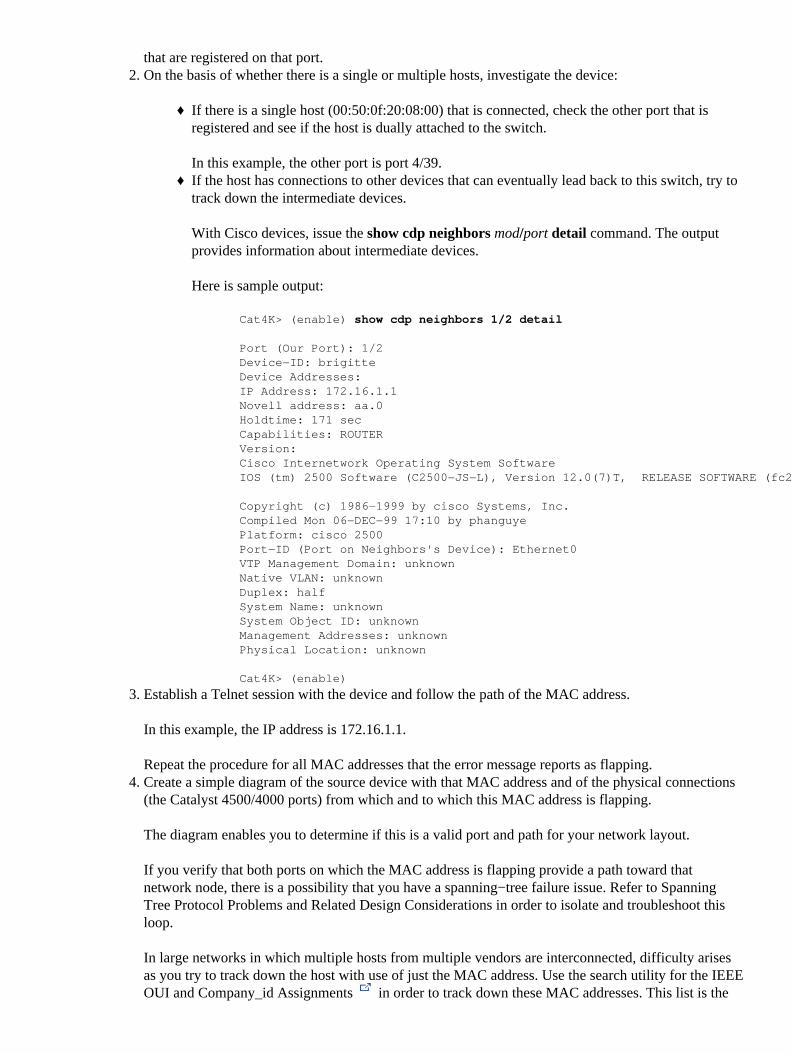
that are registered on that port.On the basis of whether there is a single or multiple hosts, investigate the device:
If there is a single host (00:50:0f:20:08:00) that is connected, check the other port that isregistered and see if the host is dually attached to the switch.
In this example, the other port is port 4/39.
♦
If the host has connections to other devices that can eventually lead back to this switch, try totrack down the intermediate devices.
With Cisco devices, issue the show cdp neighbors mod/port detail command. The outputprovides information about intermediate devices.
Here is sample output:
Cat4K> (enable) show cdp neighbors 1/2 detail
Port (Our Port): 1/2Device−ID: brigitteDevice Addresses:IP Address: 172.16.1.1Novell address: aa.0Holdtime: 171 secCapabilities: ROUTERVersion:Cisco Internetwork Operating System SoftwareIOS (tm) 2500 Software (C2500−JS−L), Version 12.0(7)T, RELEASE SOFTWARE (fc2)
Copyright (c) 1986−1999 by cisco Systems, Inc.Compiled Mon 06−DEC−99 17:10 by phanguyePlatform: cisco 2500Port−ID (Port on Neighbors's Device): Ethernet0VTP Management Domain: unknownNative VLAN: unknownDuplex: halfSystem Name: unknownSystem Object ID: unknownManagement Addresses: unknownPhysical Location: unknown
Cat4K> (enable)
♦
2.
Establish a Telnet session with the device and follow the path of the MAC address.
In this example, the IP address is 172.16.1.1.
Repeat the procedure for all MAC addresses that the error message reports as flapping.
3.
Create a simple diagram of the source device with that MAC address and of the physical connections(the Catalyst 4500/4000 ports) from which and to which this MAC address is flapping.
The diagram enables you to determine if this is a valid port and path for your network layout.
If you verify that both ports on which the MAC address is flapping provide a path toward thatnetwork node, there is a possibility that you have a spanning−tree failure issue. Refer to SpanningTree Protocol Problems and Related Design Considerations in order to isolate and troubleshoot thisloop.
In large networks in which multiple hosts from multiple vendors are interconnected, difficulty arisesas you try to track down the host with use of just the MAC address. Use the search utility for the IEEEOUI and Company_id Assignments in order to track down these MAC addresses. This list is the
4.
front end of the database where IEEE has registered all MAC addresses that have been assigned to allvendors. Enter the first three octets of the MAC address in the Search for: field of this page in orderto find the vendor that is associated with this device. The first three octets in the example are 00:50:0f.
These are other issues that can cause this message to appear:
Server NIC redundancy problem�There is a server with a dual−attached NIC that misbehaves anddoes not follow the standards. The server uses the same MAC address for both ports that connect tothe same switch.
•
Hot Standby Router Protocol (HSRP) flapping�Flapping HSRP can cause these messages toappear in the Supervisor Engine console. If you notice that HSRP implementation in your network isunstable, refer to Understanding and Troubleshooting HSRP Problems in Catalyst Switch Networks inorder to resolve the problem.
•
EtherChannel misconfiguration�A misconfigured EtherChannel connection can also cause thesesymptoms. If ports that the flapping message reports are members of the same channel group, checkyour EtherChannel configuration and refer to Understanding EtherChannel Load Balancing andRedundancy on Catalyst Switches in order to troubleshoot the configuration.
•
Host reflects packets back onto the network�The reflection of packets back onto the network by ahost can also cause flapping. Typically, the root cause of this packet reflection is a broken NIC or anyfailure of the physical interface of the host that is connected to the port.
If the reflection of packets by the host is your root cause, obtain a sniffer trace and examine the trafficthat goes to and from the ports on which the messages have appeared. If a host reflects packets, youtypically see duplicate packets in the trace. The duplicate packets are a possible symptom of thisflapping of the MAC address.
Refer to Configuring SPAN and RSPAN for details on how to configure a port for use with a sniffer.
•
Software or hardware defect�If you have tried to troubleshoot the flapping message with theinstructions in this section but you still notice the issue, seek further assistance from Cisco TechnicalSupport. Be sure to mention and provide documentation of the information that you have collectedwhile you followed the steps. This information makes further troubleshooting quicker and moreefficient.
•
%SYS−4−P2_WARN: 1/Blocked queue (tx) on port [char]
Problem
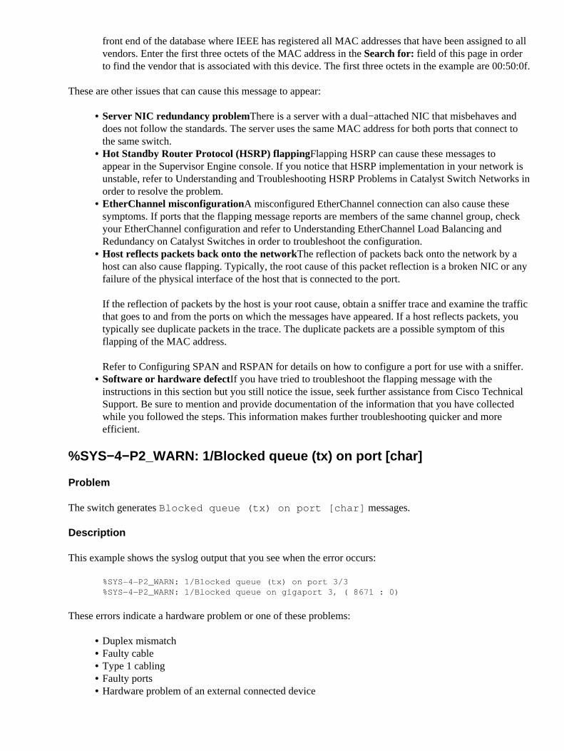
The switch generates Blocked queue (tx) on port [char] messages.
Description
This example shows the syslog output that you see when the error occurs:
%SYS−4−P2_WARN: 1/Blocked queue (tx) on port 3/3%SYS−4−P2_WARN: 1/Blocked queue on gigaport 3, ( 8671 : 0)
These errors indicate a hardware problem or one of these problems:
Duplex mismatch• Faulty cable• Type 1 cabling• Faulty ports• Hardware problem of an external connected device•
The most common cause of these errors is a physical layer problem. The problem causes a considerableamount of traffic to back up on the internal K1 gigaports. K1 application−specific integrated circuits (ASICs)are the main chips that control the switch. Generally, the blocked Tx queue count increments because of aconfiguration issue or damaged cabling.
In a normal environment, the Tx queue can only be blocked for approximately 20 seconds. A longer blockageindicates a significant problem. As a result, the blocked Tx queue count increments if the Tx queue has notdrained for the gigaport in 35 seconds.
If necessary, contact Cisco Technical Support in order to determine if the module needs replacement. Butfirst, reseat the module and see if the error message still exists.
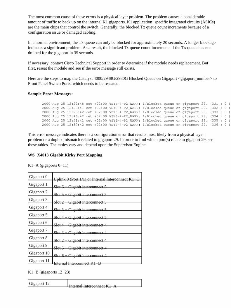
Here are the steps to map the Catalyst 4000/2948G/2980G Blocked Queue on Gigaport <gigaport_number> toFront Panel Switch Ports, which needs to be reseated.
Sample Error Messages:
2000 Aug 25 12:22:48 cet +02:00 %SYS−4−P2_WARN: 1/Blocked queue on gigaport 29, (331 : 0 )2000 Aug 25 12:23:41 cet +02:00 %SYS−4−P2_WARN: 1/Blocked queue on gigaport 29, (332 : 0 )2000 Aug 25 12:25:42 cet +02:00 %SYS−4−P2_WARN: 1/Blocked queue on gigaport 29, (333 : 0 )2000 Aug 25 12:46:42 cet +02:00 %SYS−4−P2_WARN: 1/Blocked queue on gigaport 29, (334 : 0 )2000 Aug 25 12:48:41 cet +02:00 %SYS−4−P2_WARN: 1/Blocked queue on gigaport 29, (335 : 0 )2000 Aug 25 12:57:42 cet +02:00 %SYS−4−P2_WARN: 1/Blocked queue on gigaport 29, (336 : 0 )
This error message indicates there is a configuration error that results most likely from a physical layerproblem or a duplex mismatch related to gigaport 29. In order to find which port(s) relate to gigaport 29, seethese tables. The tables vary and depend upon the Supervisor Engine.
WS−X4013 Gigabit Kirky Port Mapping
K1−A (gigaports 0−11)
Gigaport 0Uplink 0 (Port 1/1) or Internal Interconnect K1−C
Gigaport 1Slot 6 − Gigabit interconnect 5
Gigaport 2Slot 5 − Gigabit interconnect 5
Gigaport 3Slot 2 − Gigabit interconnect 5
Gigaport 4Slot 3 − Gigabit interconnect 5
Gigaport 5Slot 4 − Gigabit interconnect 5
Gigaport 6Slot 4 − Gigabit interconnect 4
Gigaport 7Slot 3 − Gigabit interconnect 4
Gigaport 8Slot 2 − Gigabit interconnect 4
Gigaport 9Slot 5 − Gigabit interconnect 4
Gigaport 10Slot 6 − Gigabit interconnect 4
Gigaport 11Internal Interconnect K1−B
K1−B (gigaports 12−23)
Gigaport 12Internal Interconnect K1−A
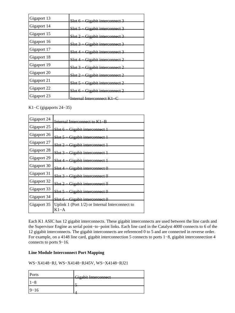
Gigaport 13Slot 6 − Gigabit interconnect 3
Gigaport 14Slot 5 − Gigabit interconnect 3
Gigaport 15Slot 2 − Gigabit interconnect 3
Gigaport 16Slot 3 − Gigabit interconnect 3
Gigaport 17Slot 4 − Gigabit interconnect 3
Gigaport 18Slot 4 − Gigabit interconnect 2
Gigaport 19Slot 3 − Gigabit interconnect 2
Gigaport 20Slot 2 − Gigabit interconnect 2
Gigaport 21Slot 5 − Gigabit interconnect 2
Gigaport 22Slot 6 − Gigabit interconnect 2
Gigaport 23Internal Interconnect K1−C
K1−C (gigaports 24−35)
Gigaport 24Internal Interconnect to K1−B
Gigaport 25Slot 6 − Gigabit interconnect 1
Gigaport 26Slot 5 − Gigabit interconnect 1
Gigaport 27Slot 2 − Gigabit interconnect 1
Gigaport 28Slot 3 − Gigabit interconnect 1
Gigaport 29Slot 4 − Gigabit interconnect 1
Gigaport 30Slot 4 − Gigabit interconnect 0
Gigaport 31Slot 3 − Gigabit interconnect 0
Gigaport 32Slot 2 − Gigabit interconnect 0
Gigaport 33Slot 5 − Gigabit interconnect 0
Gigaport 34Slot 6 − Gigabit interconnect 0
Gigaport 35 Uplink 1 (Port 1/2) or Internal Interconnect toK1−A
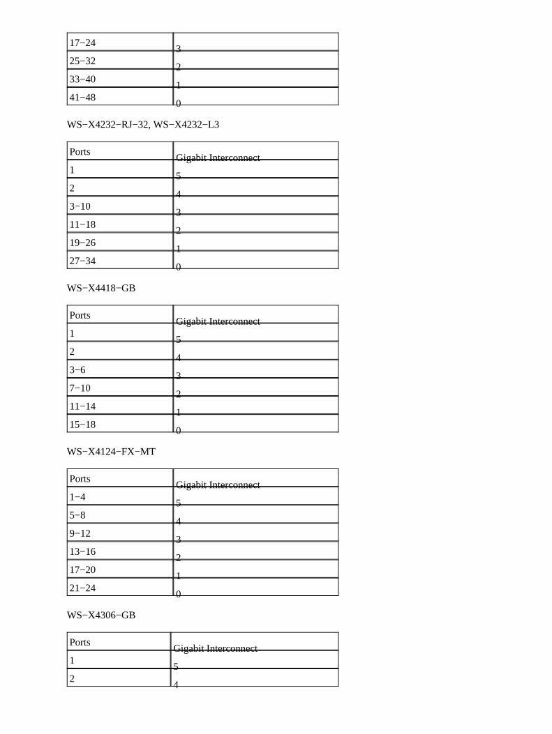
Each K1 ASIC has 12 gigabit interconnects. These gigabit interconnects are used between the line cards andthe Supervisor Engine as serial point−to−point links. Each line card in the Catalyst 4000 connects to 6 of the12 gigabit interconnects. The gigabit interconnects are referenced 0 to 5 and are connected in reverse order.For example, on a 4148 line card, gigabit interconnection 5 connects to ports 1−8, gigabit interconnection 4connects to ports 9−16.
Line Module Interconnect Port Mapping
WS−X4148−RJ, WS−X4148−RJ45V, WS−X4148−RJ21
PortsGigabit Interconnect
1−85
9−164
17−243
25−322
33−401
41−480
WS−X4232−RJ−32, WS−X4232−L3
PortsGigabit Interconnect
15
24
3−103
11−182
19−261
27−340
WS−X4418−GB
PortsGigabit Interconnect
15
24
3−63
7−102
11−141
15−180
WS−X4124−FX−MT
PortsGigabit Interconnect
1−45
5−84
9−123
13−162
17−201
21−240
WS−X4306−GB
PortsGigabit Interconnect
15
24
33
42
51
60
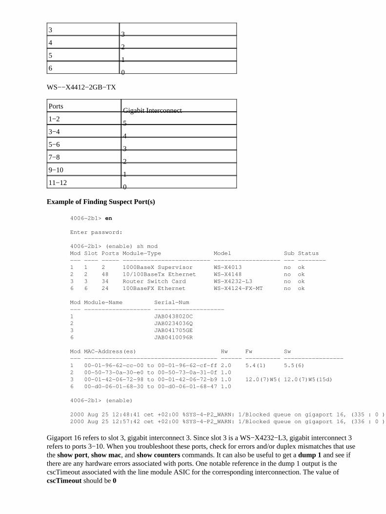
WS−−X4412−2GB−TX
PortsGigabit Interconnect
1−25
3−44
5−63
7−82
9−101
11−120
Example of Finding Suspect Port(s)
4006−2b1> en
Enter password:
4006−2b1> (enable) sh modMod Slot Ports Module−Type Model Sub Status−−− −−−− −−−−− −−−−−−−−−−−−−−−−−−−−−−−−− −−−−−−−−−−−−−−−−−−− −−− −−−−−−−−1 1 2 1000BaseX Supervisor WS−X4013 no ok2 2 48 10/100BaseTx Ethernet WS−X4148 no ok3 3 34 Router Switch Card WS−X4232−L3 no ok6 6 24 100BaseFX Ethernet WS−X4124−FX−MT no ok
Mod Module−Name Serial−Num−−− −−−−−−−−−−−−−−−−−−− −−−−−−−−−−−−−−−−−−−−1 JAB0438020C2 JAB0234036Q3 JAB041705GE6 JAB0410096R
Mod MAC−Address(es) Hw Fw Sw−−− −−−−−−−−−−−−−−−−−−−−−−−−−−−−−−−−−−−−−− −−−−−− −−−−−−−−−− −−−−−−−−−−−−−−−−−1 00−01−96−62−cc−00 to 00−01−96−62−cf−ff 2.0 5.4(1) 5.5(6)2 00−50−73−0a−30−e0 to 00−50−73−0a−31−0f 1.03 00−01−42−06−72−98 to 00−01−42−06−72−b9 1.0 12.0(7)W5( 12.0(7)W5(15d)6 00−d0−06−01−68−30 to 00−d0−06−01−68−47 1.0
4006−2b1> (enable)
2000 Aug 25 12:48:41 cet +02:00 %SYS−4−P2_WARN: 1/Blocked queue on gigaport 16, (335 : 0 )2000 Aug 25 12:57:42 cet +02:00 %SYS−4−P2_WARN: 1/Blocked queue on gigaport 16, (336 : 0 )
Gigaport 16 refers to slot 3, gigabit interconnect 3. Since slot 3 is a WS−X4232−L3, gigabit interconnect 3refers to ports 3−10. When you troubleshoot these ports, check for errors and/or duplex mismatches that usethe show port, show mac, and show counters commands. It can also be useful to get a dump 1 and see ifthere are any hardware errors associated with ports. One notable reference in the dump 1 output is thecscTimeout associated with the line module ASIC for the corresponding interconnection. The value ofcscTimeout should be 0
%SYS−4−P2_WARN: 1/Filtering Ethernet MAC address of value zero
Problem
The switch generates Filtering Ethernet MAC address of value zero messages.
Description
This example shows the syslog output that you see when this error occurs:
%SYS−4−P2_WARN: 1/Filtering Ethernet MAC address of value zero from agent host table interface%SYS−4−P2_WARN: 1/Filtering Ethernet MAC address of value zero from agent host table interface
The switch generates the Filtering Ethernet MAC address of value zero syslog messagewhen the switch receives packets with a source MAC address of 00−00−00−00−00−00. This MAC address isan invalid source MAC.
The syslog message indicates that the switch refuses to learn the invalid address. However, the switchforwards traffic that is sourced from an all−zeros MAC address.
The workaround is to try to identify the end station that generates frames with an all−zeros source MACaddress. Typically, one of these devices transmits such frames:
A traffic generator, such as Spirent SmartBits• Certain types of servers, such as load−balancing IBM WebSphere servers• A misconfigured router or end station, such as a device that transmits all−zeros broadcasts• A faulty NIC•
%SYS−4−P2_WARN: 1/Invalid crc, dropped packet, count = xx
Problem
The switch with Supervisor Engine II (WS−X4013=) generates the message that this section shows and youexperience partial or full loss of network connectivity. The loss of connectivity may affect only a portion ofthe switch ports and may include the uplink ports.
%SYS−4−P2_WARN: 1/Invalid crc, dropped packet, count = xx
Description
This example shows the syslog or console output that you see when this error occurs:
%SYS−4−P2_WARN: 1/Invalid crc, dropped packet, count = 590073 %SYS−4−P2_WARN: 1/Invalid crc, dropped packet, count = 594688
Sometimes, you also see this message:
%SYS−4−P2_WARN: 1/Astro(3/4) − management request timed out
Note: If you only get the %SYS−4−P2_WARN: 1/Astro(3/4) − management request timedout message, see the %SYS−4−P2_WARN: 1/Astro(mod/port) section of this document.
Note: You may experience network connectivity issues when these messages appear.
Follow these troubleshooting steps and capture the output of commands during each step:
Note: Contact Cisco Technical Support for assistance in troubleshooting.
Issue these commands:
show logging buffer −1023a. show tech−supportb. show health 1c. dump 1d.
1.
Issue one of these commands five times, at random intervals, and observe theInvalidPacketBufferCrcs counter:
show nvramenv 1�CatOS software release 6.1(1) or later
Cat4k> (enable) show nvramenv 1
PS1="rommon ! >"?="0"DiagBootMode="post"MemorySize="64"ResetCause="20"AutobootStatus="success"InvalidPacketBufferCrcs="82325"
♦
show env 1�CatOS software release 5.5(19) or earlier♦ As you repeat the command, observe whether the InvalidPacketBufferCrcs counter increasesrapidly by high values.
cat4k> (enable) show nvramenv 1
PS1="rommon ! >"?="0"DiagBootMode="post"MemorySize="64"ResetCause="20"AutobootStatus="success"InvalidPacketBufferCrcs="82763"
Note: If you see a small number of InvalidPacketBufferCrcs in the output and you run aCatOS software version that is earlier than 5.5.10, 6.2.3, or 6.3.1, upgrade to a later release. There is apossibility that you have encountered Cisco bug ID CSCdu48749 (registered customers only) andCSCdt80707 (registered customers only) . Refer to Field Notice: Catalyst 4000 Ports Lose ActiveVLAN State Resulting in Packet Loss for further information.
2.
If you find that the InvalidPacketBufferCrcs counter increases at a high rate, issue the resetcommand in order to soft reset the switch.
Note: The capture of output in this step is critical.
cat4k> (enable) reset
This command will reset the system.Do you want to continue (y/n) [n]? y
nodcsw0nm1> (enable)WS−X4013 bootrom version 5.4(1), built on 2000.02.17 18:28:09H/W Revisions: Crumb: 5 Rancor: 8 Board: 2Supervisor MAC addresses: 00:0a:8a:6d:92:00 through 00:0a:8a:6d:95:ff(1024 addresses)Installed memory: 64 MBTesting LEDs.... done!
3.
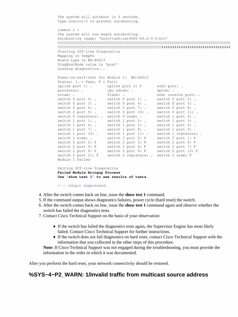
The system will autoboot in 5 seconds.Type control−C to prevent autobooting.
rommon 1 >The system will now begin autobooting.Autobooting image: "bootflash:cat4000−k9.6−3−9.bin"CCCCCCCCCCCCCCCCCCCCCCCCCCCCCCCCCCCCCCCCCCCCCCCCCCCCCCCCCCCCCCCCCCCCCCCCCCCCCCCCCCCCCCCCCCCCCCCCCCCCCCCCCCCCCCCCCCCCCCCCCCCCCCCC################################Starting Off−line DiagnosticsMapping in TempFsBoard type is WS−X4013DiagBootMode value is "post"Loading diagnostics...
Power−on−self−test for Module 1: WS−X4013Status: (. = Pass, F = Fail)uplink port 1: . uplink port 2: F eobc port: .processor: . cpu sdram: . eprom: .nvram: . flash: . enet console port: .switch 0 port 0: . switch 0 port 1: . switch 0 port 2: .switch 0 port 3: . switch 0 port 4: . switch 0 port 5: .switch 0 port 6: . switch 0 port 7: . switch 0 port 8: .switch 0 port 9: . switch 0 port 10: . switch 0 port 11: .switch 0 registers: . switch 0 sram: . switch 1 port 0: .switch 1 port 1: . switch 1 port 2: . switch 1 port 3: .switch 1 port 4: . switch 1 port 5: . switch 1 port 6: .switch 1 port 7: . switch 1 port 8: . switch 1 port 9: .switch 1 port 10: . switch 1 port 11: . switch 1 registers: .switch 1 sram: . switch 2 port 0: F switch 2 port 1: Fswitch 2 port 2: F switch 2 port 3: F switch 2 port 4: Fswitch 2 port 5: F switch 2 port 6: F switch 2 port 7: Fswitch 2 port 8: F switch 2 port 9: F switch 2 port 10: Fswitch 2 port 11: F switch 2 registers: . switch 2 sram: FModule 1 Failed
Exiting Off−line DiagnosticsFailed Module Bringup ProcessUse 'show test 1' to see results of tests.
!−−− Output suppressed.
After the switch comes back on line, issue the show test 1 command.4. If the command output shows diagnostics failures, power cycle (hard reset) the switch.5. After the switch comes back on line, issue the show test 1 command again and observe whether theswitch has failed the diagnostics tests.
6.
Contact Cisco Technical Support on the basis of your observation:
If the switch has failed the diagnostics tests again, the Supervisor Engine has most likelyfailed. Contact Cisco Technical Support for further instructions.
♦
If the switch does not fail diagnostics on hard reset, contact Cisco Technical Support with theinformation that you collected in the other steps of this procedure.
♦
Note: If Cisco Technical Support was not engaged during the troubleshooting, you must provide theinformation in the order in which it was documented.
7.
After you perform the hard reset, your network connectivity should be restored.
%SYS−4−P2_WARN: 1/Invalid traffic from multicast source address
Problem
The switch generates Invalid traffic from multicast source address messages.
Description
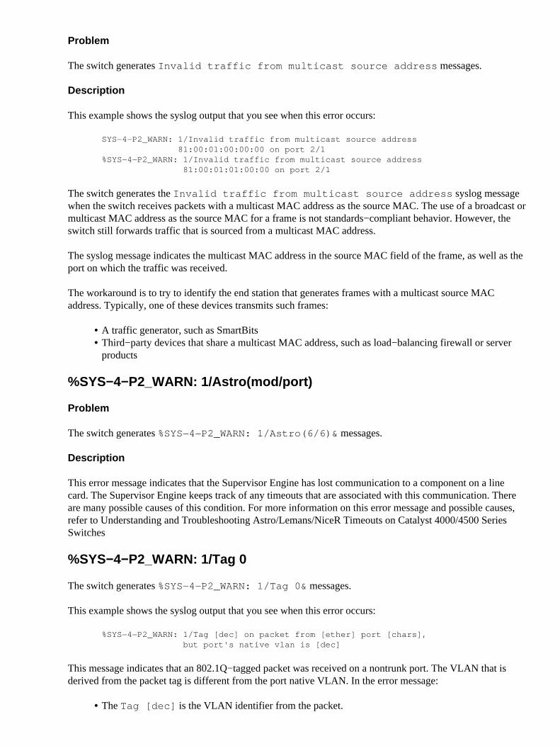
This example shows the syslog output that you see when this error occurs:
SYS−4−P2_WARN: 1/Invalid traffic from multicast source address 81:00:01:00:00:00 on port 2/1%SYS−4−P2_WARN: 1/Invalid traffic from multicast source address 81:00:01:01:00:00 on port 2/1
The switch generates the Invalid traffic from multicast source address syslog messagewhen the switch receives packets with a multicast MAC address as the source MAC. The use of a broadcast ormulticast MAC address as the source MAC for a frame is not standards−compliant behavior. However, theswitch still forwards traffic that is sourced from a multicast MAC address.
The syslog message indicates the multicast MAC address in the source MAC field of the frame, as well as theport on which the traffic was received.
The workaround is to try to identify the end station that generates frames with a multicast source MACaddress. Typically, one of these devices transmits such frames:
A traffic generator, such as SmartBits• Third−party devices that share a multicast MAC address, such as load−balancing firewall or serverproducts
•
%SYS−4−P2_WARN: 1/Astro(mod/port)
Problem
The switch generates %SYS−4−P2_WARN: 1/Astro(6/6)& messages.
Description
This error message indicates that the Supervisor Engine has lost communication to a component on a linecard. The Supervisor Engine keeps track of any timeouts that are associated with this communication. Thereare many possible causes of this condition. For more information on this error message and possible causes,refer to Understanding and Troubleshooting Astro/Lemans/NiceR Timeouts on Catalyst 4000/4500 SeriesSwitches
%SYS−4−P2_WARN: 1/Tag 0
The switch generates %SYS−4−P2_WARN: 1/Tag 0& messages.
This example shows the syslog output that you see when this error occurs:
%SYS−4−P2_WARN: 1/Tag [dec] on packet from [ether] port [chars], but port's native vlan is [dec]
This message indicates that an 802.1Q−tagged packet was received on a nontrunk port. The VLAN that isderived from the packet tag is different from the port native VLAN. In the error message:
The Tag [dec] is the VLAN identifier from the packet.•
The [ether] is the host MAC address.• The port [chars] is the port identifier.• The second [dec] is the native VLAN number.•
There is a possibility that the local port is incorrectly configured as an access port instead of a trunk port.Alternately, the remote side can have been configured as a trunk port instead of an access port.
Verify that the local port is not incorrectly configured as an access port instead of a trunk port. Also, verifythat the remote side is not configured as a trunk port instead of an access port.
convert_post_SAC_CiscoMIB:Nvram block [#] unconvertible
Problem
The switch generates periodic convert_post_SAC_CiscoMIB: syslog messages.
Description
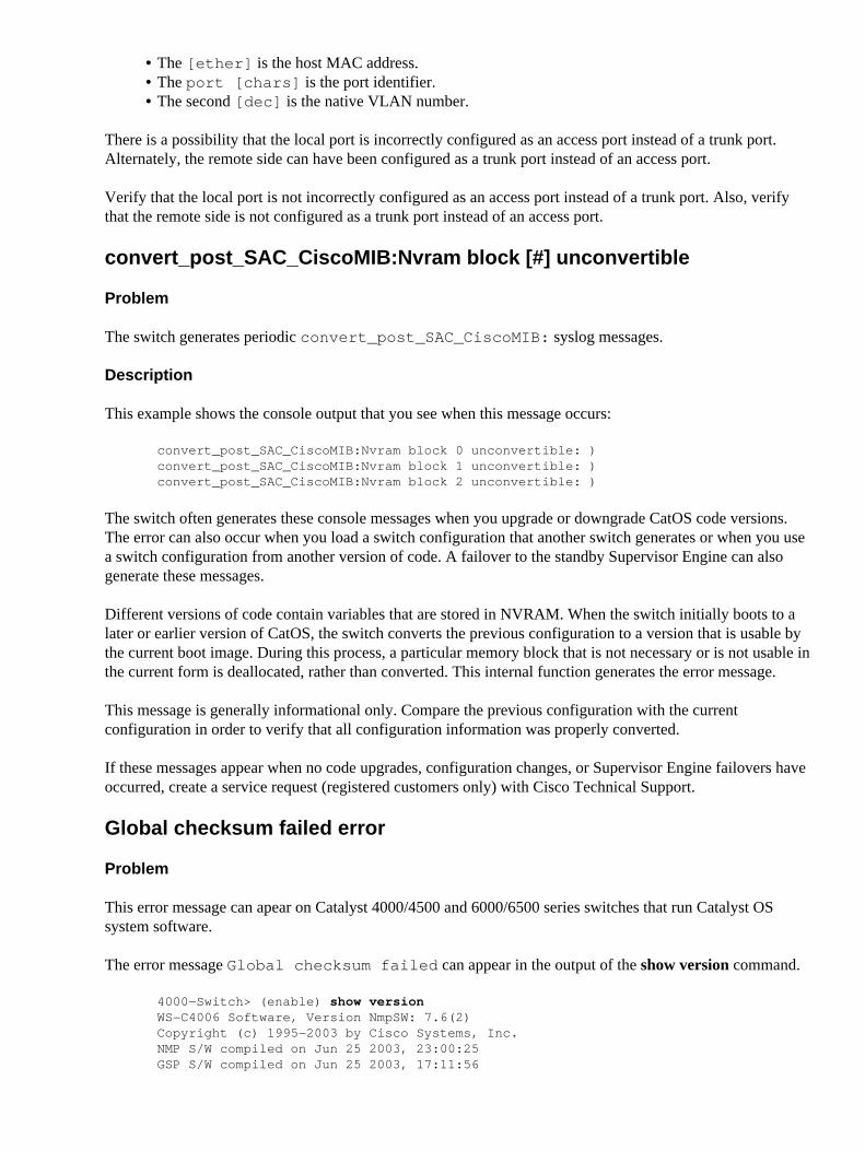
This example shows the console output that you see when this message occurs:
convert_post_SAC_CiscoMIB:Nvram block 0 unconvertible: )convert_post_SAC_CiscoMIB:Nvram block 1 unconvertible: )convert_post_SAC_CiscoMIB:Nvram block 2 unconvertible: )
The switch often generates these console messages when you upgrade or downgrade CatOS code versions.The error can also occur when you load a switch configuration that another switch generates or when you usea switch configuration from another version of code. A failover to the standby Supervisor Engine can alsogenerate these messages.
Different versions of code contain variables that are stored in NVRAM. When the switch initially boots to alater or earlier version of CatOS, the switch converts the previous configuration to a version that is usable bythe current boot image. During this process, a particular memory block that is not necessary or is not usable inthe current form is deallocated, rather than converted. This internal function generates the error message.
This message is generally informational only. Compare the previous configuration with the currentconfiguration in order to verify that all configuration information was properly converted.
If these messages appear when no code upgrades, configuration changes, or Supervisor Engine failovers haveoccurred, create a service request (registered customers only) with Cisco Technical Support.
Global checksum failed error
Problem
This error message can apear on Catalyst 4000/4500 and 6000/6500 series switches that run Catalyst OSsystem software.
The error message Global checksum failed can appear in the output of the show version command.
4000−Switch> (enable) show versionWS−C4006 Software, Version NmpSW: 7.6(2)Copyright (c) 1995−2003 by Cisco Systems, Inc.NMP S/W compiled on Jun 25 2003, 23:00:25GSP S/W compiled on Jun 25 2003, 17:11:56
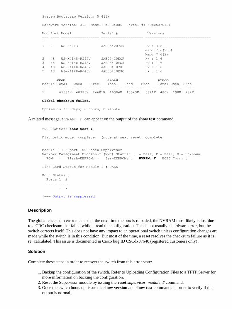
System Bootstrap Version: 5.4(1)
Hardware Version: 3.2 Model: WS−C4006 Serial #: FOX053701JY
Mod Port Model Serial # Versions−−− −−−− −−−−−−−−−−−−−−−−−− −−−−−−−−−−−−−−−−−−−− −−−−−−−−−−−−−−−−−−−−−−−−−−−−−−−−−1 2 WS−X4013 JAB054207A0 Hw : 3.2 Gsp: 7.6(2.0) Nmp: 7.6(2)2 48 WS−X4148−RJ45V JAB05410EQF Hw : 1.63 48 WS−X4148−RJ45V JAB05410ES5 Hw : 1.64 48 WS−X4148−RJ45V JAB0541070L Hw : 1.65 48 WS−X4148−RJ45V JAB05410ESC Hw : 1.6
DRAM FLASH NVRAMModule Total Used Free Total Used Free Total Used Free−−−−−− −−−−−−− −−−−−−− −−−−−−− −−−−−−− −−−−−−− −−−−−−− −−−−− −−−−− −−−−−1 65536K 40935K 24601K 16384K 10543K 5841K 480K 198K 282K
Global checksum failed.
Uptime is 306 days, 8 hours, 0 minute
A related message, NVRAM: F, can appear on the output of the show test command.
6000−Switch> show test 1
Diagnostic mode: complete (mode at next reset: complete)
Module 1 : 2−port 1000BaseX SupervisorNetwork Management Processor (NMP) Status: (. = Pass, F = Fail, U = Unknown) ROM: . Flash−EEPROM: . Ser−EEPROM: . NVRAM: F EOBC Comm: .
Line Card Status for Module 1 : PASS
Port Status : Ports 1 2 −−−−−−−−−−− . .
!−−− Output is suppressed.
Description
The global checksum error means that the next time the box is reloaded, the NVRAM most likely is lost dueto a CRC checksum that failed while it read the configuration. This is not usually a hardware error, but theswitch corrects itself. This does not have any impact to an operational switch unless configuration changes aremade while the switch is in this condition. But most of the time, a reset resolves the checksum failure as it isre−calculated. This issue is documented in Cisco bug ID CSCdx87646 (registered customers only) .
Solution
Complete these steps in order to recover the switch from this error state:
Backup the configuration of the switch. Refer to Uploading Configuration Files to a TFTP Server formore information on backing the configuration.
1.
Reset the Supervisor module by issuing the reset supervisor_module_# command.2. Once the switch boots up, issue the show version and show test commands in order to verify if theoutput is normal.
3.
Verify the configuration existing on the switch, and restore from the backup if required.4.
Related Information
System Message Guide Catalyst Family Switches, 7.4• Configuring System Message Logging• Common CatOS Error Messages on Catalyst 5000/5500 Series Switches• Common CatOS Error Messages on Catalyst 6500/6000 Series Switches• Error Message Decoder ( registered customers only)• LAN Product Support Pages• LAN Switching Support Page• Technical Support & Documentation − Cisco Systems•
Contacts & Feedback | Help | Site Map© 2013 − 2014 Cisco Systems, Inc. All rights reserved. Terms & Conditions | Privacy Statement | Cookie Policy | Trademarks ofCisco Systems, Inc.
Updated: Feb 05, 2007 Document ID: 30003