Embed Size (px)
Citation preview
0017ENG Rev.01 01/02/2017
AGOM INTERNATIONAL SRL Via Mesero, 12 – 20010 Ossona (MI) – Italy - www.agom.it
PH.: +39 02 9029111 – FAX: +39 02 9010201 – [email protected] B
UR
IED
JO
INTS
Pag 2
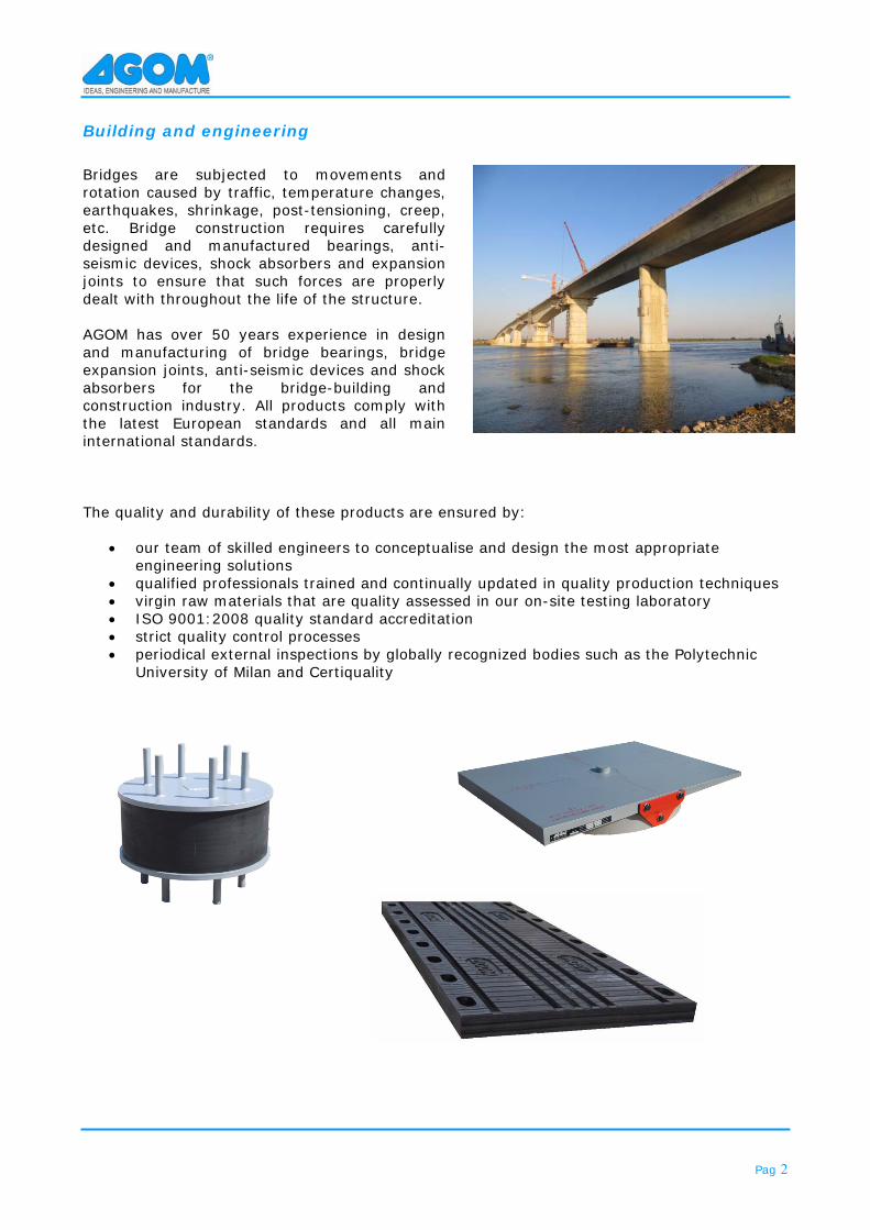
Building and engineering Bridges are subjected to movements and rotation caused by traffic, temperature changes, earthquakes, shrinkage, post-tensioning, creep, etc. Bridge construction requires carefully designed and manufactured bearings, anti-seismic devices, shock absorbers and expansion joints to ensure that such forces are properly dealt with throughout the life of the structure. AGOM has over 50 years experience in design and manufacturing of bridge bearings, bridge expansion joints, anti-seismic devices and shock absorbers for the bridge-building and construction industry. All products comply with the latest European standards and all main international standards. The quality and durability of these products are ensured by:
our team of skilled engineers to conceptualise and design the most appropriate engineering solutions
qualified professionals trained and continually updated in quality production techniques virgin raw materials that are quality assessed in our on-site testing laboratory ISO 9001:2008 quality standard accreditation strict quality control processes periodical external inspections by globally recognized bodies such as the Polytechnic
University of Milan and Certiquality
Pag 3
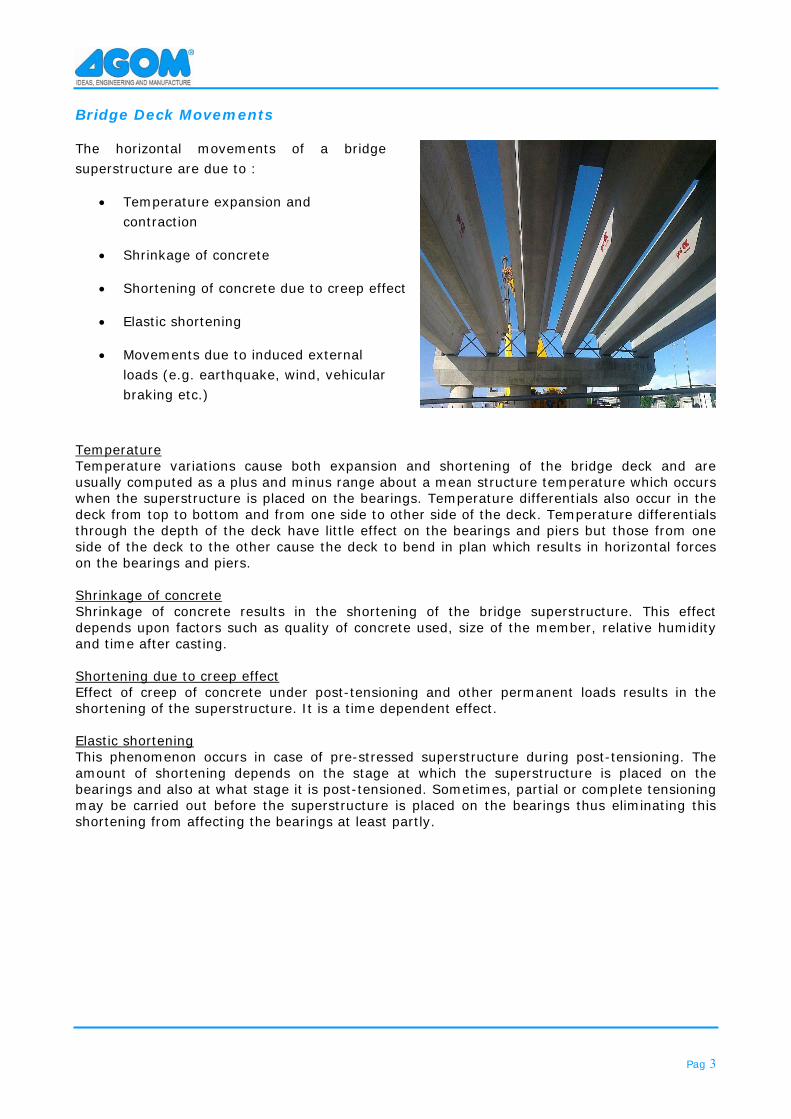
Bridge Deck Movements
The horizontal movements of a bridge superstructure are due to :
Temperature expansion and contraction
Shrinkage of concrete
Shortening of concrete due to creep effect
Elastic shortening
Movements due to induced external loads (e.g. earthquake, wind, vehicular braking etc.)
Temperature Temperature variations cause both expansion and shortening of the bridge deck and are usually computed as a plus and minus range about a mean structure temperature which occurs when the superstructure is placed on the bearings. Temperature differentials also occur in the deck from top to bottom and from one side to other side of the deck. Temperature differentials through the depth of the deck have little effect on the bearings and piers but those from one side of the deck to the other cause the deck to bend in plan which results in horizontal forces on the bearings and piers. Shrinkage of concrete Shrinkage of concrete results in the shortening of the bridge superstructure. This effect depends upon factors such as quality of concrete used, size of the member, relative humidity and time after casting. Shortening due to creep effect Effect of creep of concrete under post-tensioning and other permanent loads results in the shortening of the superstructure. It is a time dependent effect. Elastic shortening This phenomenon occurs in case of pre-stressed superstructure during post-tensioning. The amount of shortening depends on the stage at which the superstructure is placed on the bearings and also at what stage it is post-tensioned. Sometimes, partial or complete tensioning may be carried out before the superstructure is placed on the bearings thus eliminating this shortening from affecting the bearings at least partly.
Pag 4
Buried joints series
Buried expansion joints are designed and manufactured for small movements between structures, up to ±25 mm. These joints are generally put under the asphalt, in order to guarantee the continuity of the surface of vehicle transit.
They are often associated to kinematic chain system, that will absorb the longitudinal forces.
Feature Benefit
Quality Made of certificated materials.
Efficiency Minimal maintenance requirements.
Easiness Easy to install.
Comfort Asphalt is not interrupted, so increasing the comfort of vehicles.
Maintenance of road No problem for snowploughs.
Pag 5
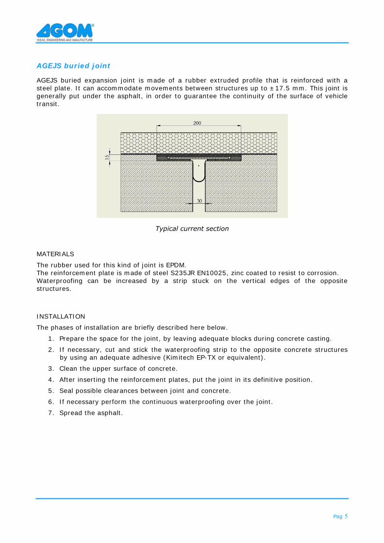
AGEJS buried joint
AGEJS buried expansion joint is made of a rubber extruded profile that is reinforced with a steel plate. It can accommodate movements between structures up to ±17.5 mm. This joint is generally put under the asphalt, in order to guarantee the continuity of the surface of vehicle transit.
Typical current section
MATERIALS
The rubber used for this kind of joint is EPDM. The reinforcement plate is made of steel S235JR EN10025, zinc coated to resist to corrosion. Waterproofing can be increased by a strip stuck on the vertical edges of the opposite structures.
INSTALLATION
The phases of installation are briefly described here below.
1. Prepare the space for the joint, by leaving adequate blocks during concrete casting.
2. If necessary, cut and stick the waterproofing strip to the opposite concrete structures by using an adequate adhesive (Kimitech EP-TX or equivalent).
3. Clean the upper surface of concrete.
4. After inserting the reinforcement plates, put the joint in its definitive position.
5. Seal possible clearances between joint and concrete.
6. If necessary perform the continuous waterproofing over the joint.
7. Spread the asphalt.
Pag 6
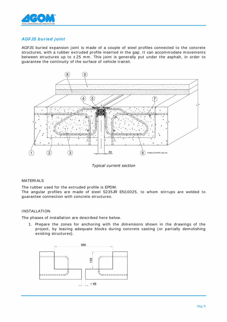
AGFJS buried joint
AGFJS buried expansion joint is made of a couple of steel profiles connected to the concrete structures, with a rubber extruded profile inserted in the gap. It can accommodate movements between structures up to ±25 mm. This joint is generally put under the asphalt, in order to guarantee the continuity of the surface of vehicle transit.
Typical current section
MATERIALS
The rubber used for the extruded profile is EPDM. The angular profiles are made of steel S235JR EN10025, to whom stirrups are welded to guarantee connection with concrete structures.
INSTALLATION
The phases of installation are described here below.
1. Prepare the zones for anchoring with the dimensions shown in the drawings of the project, by leaving adequate blocks during concrete casting (or partially demolishing existing structures).
Pag 7
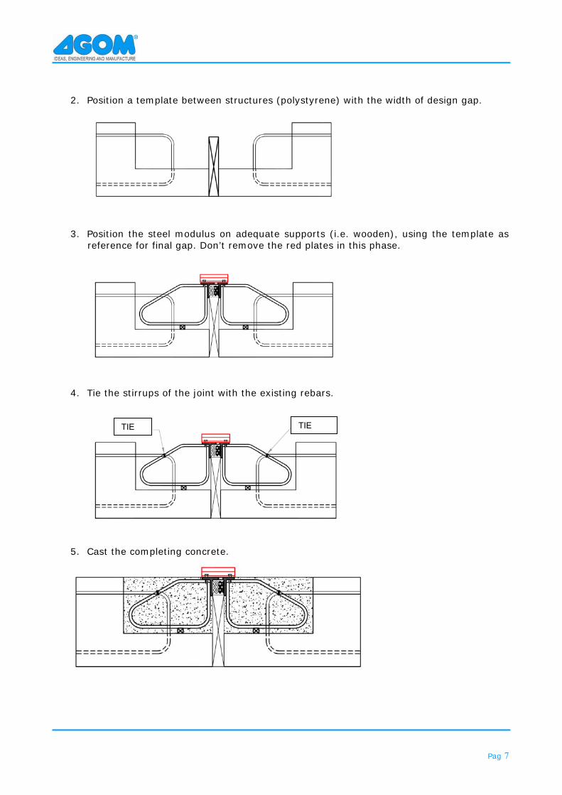
2. Position a template between structures (polystyrene) with the width of design gap.
3. Position the steel modulus on adequate supports (i.e. wooden), using the template as reference for final gap. Don’t remove the red plates in this phase.
4. Tie the stirrups of the joint with the existing rebars.
5. Cast the completing concrete.
TIE TIE
Pag 8
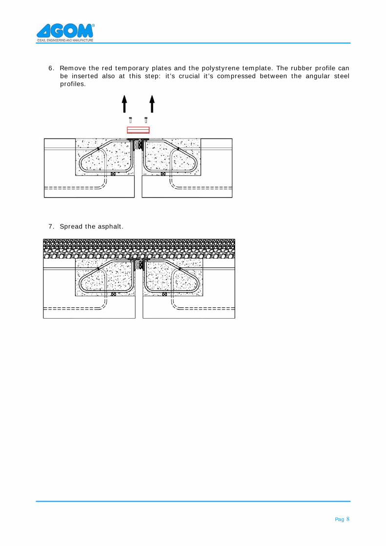
6. Remove the red temporary plates and the polystyrene template. The rubber profile can be inserted also at this step: it’s crucial it’s compressed between the angular steel profiles.
7. Spread the asphalt.
Pag 9
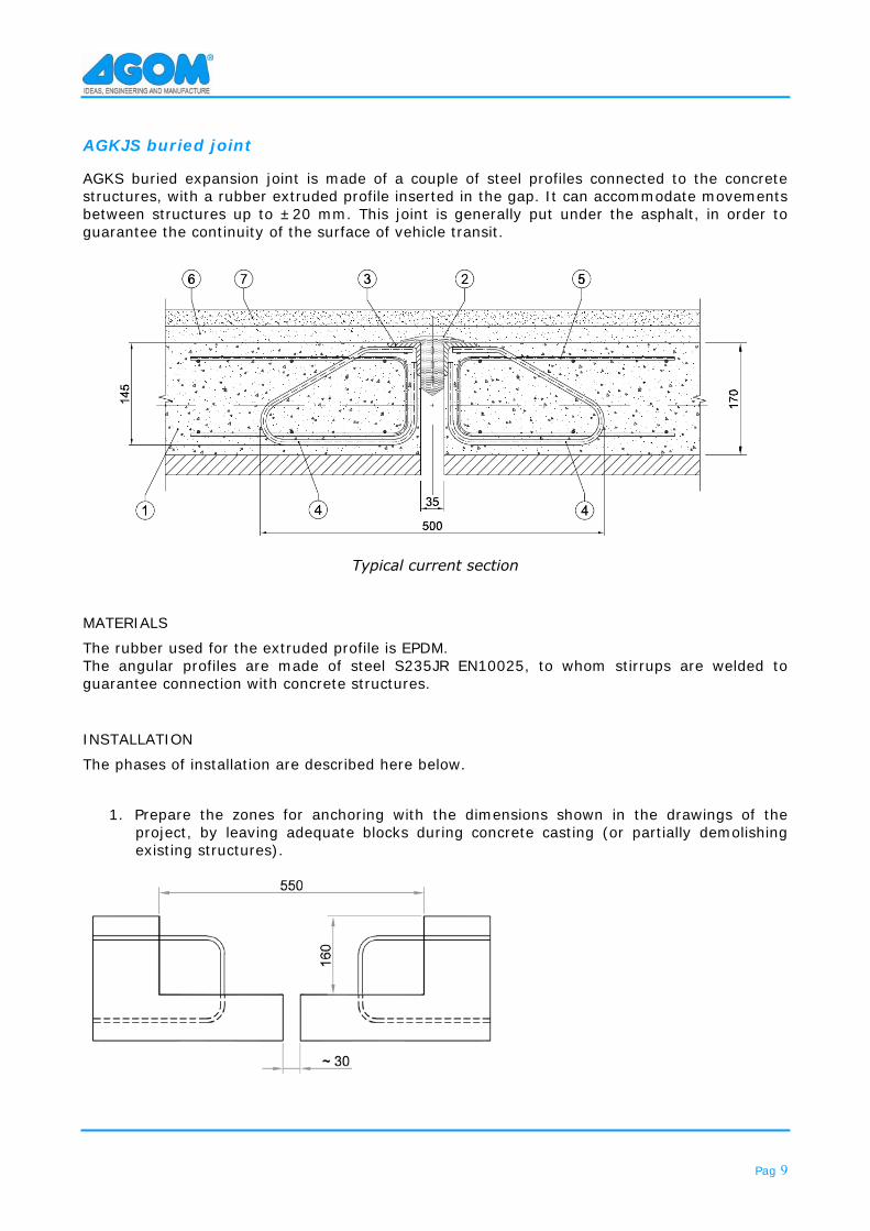
AGKJS buried joint
AGKS buried expansion joint is made of a couple of steel profiles connected to the concrete structures, with a rubber extruded profile inserted in the gap. It can accommodate movements between structures up to ±20 mm. This joint is generally put under the asphalt, in order to guarantee the continuity of the surface of vehicle transit.
Typical current section
MATERIALS
The rubber used for the extruded profile is EPDM. The angular profiles are made of steel S235JR EN10025, to whom stirrups are welded to guarantee connection with concrete structures.
INSTALLATION
The phases of installation are described here below.
1. Prepare the zones for anchoring with the dimensions shown in the drawings of the project, by leaving adequate blocks during concrete casting (or partially demolishing existing structures).
Pag 10
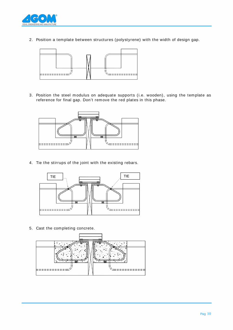
2. Position a template between structures (polystyrene) with the width of design gap.
3. Position the steel modulus on adequate supports (i.e. wooden), using the template as reference for final gap. Don’t remove the red plates in this phase.
4. Tie the stirrups of the joint with the existing rebars.
5. Cast the completing concrete.
TIE TIE
Pag 11
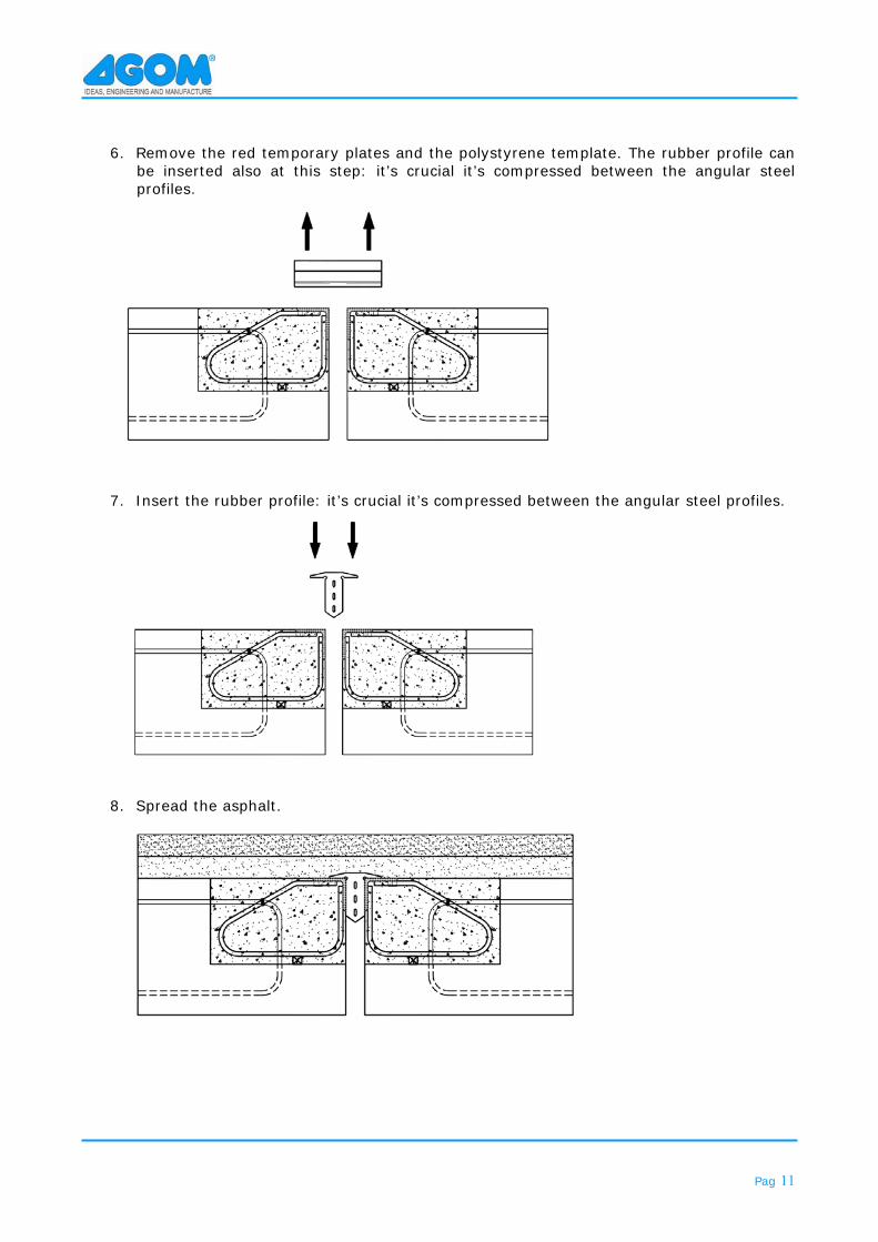
6. Remove the red temporary plates and the polystyrene template. The rubber profile can be inserted also at this step: it’s crucial it’s compressed between the angular steel profiles.
7. Insert the rubber profile: it’s crucial it’s compressed between the angular steel profiles.
8. Spread the asphalt.
Pag 12
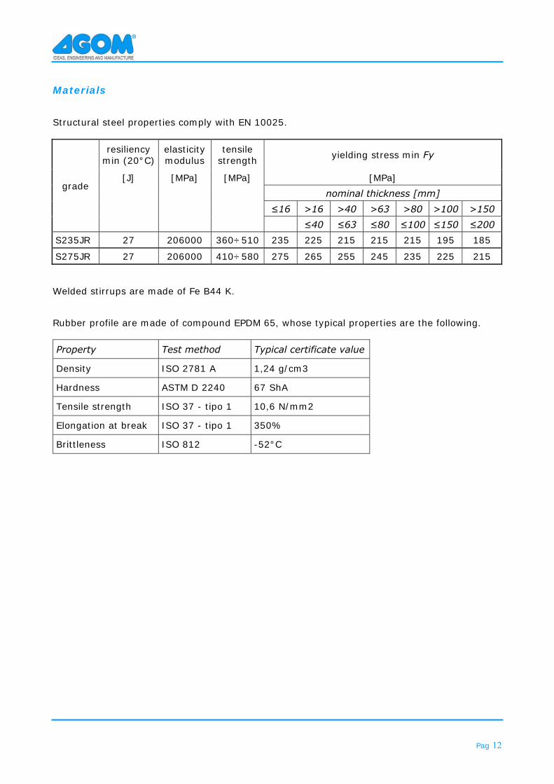
Materials Structural steel properties comply with EN 10025.
grade
resiliency min (20°C)
elasticity modulus
tensile strength yielding stress min Fy
[J] [MPa] [MPa] [MPa]
nominal thickness [mm]
≤16 >16 >40 >63 >80 >100 >150 ≤40 ≤63 ≤80 ≤100 ≤150 ≤200
S235JR 27 206000 360÷510 235 225 215 215 215 195 185
S275JR 27 206000 410÷580 275 265 255 245 235 225 215 Welded stirrups are made of Fe B44 K. Rubber profile are made of compound EPDM 65, whose typical properties are the following. Property Test method Typical certificate value
Density ISO 2781 A 1,24 g/cm3
Hardness ASTM D 2240 67 ShA
Tensile strength ISO 37 - tipo 1 10,6 N/mm2
Elongation at break ISO 37 - tipo 1 350%
Brittleness ISO 812 -52°C
Pag 13
Maintenance and replacement AGOM AG_JS expansion joints are designed to be free from maintenance, as they are put in a zone generally not reachable. We suggest to perform the following inspections to guarantee the joint right functioning:
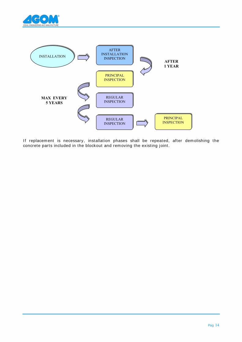
1. a first inspection just at the end of installation to verify the right positioning; 2. an inspection after a year of service, in order to visually detect any eventual damage of
the asphalt in the adjacent zones of joint; during inspection, the asphalt surface must be checked in order to verify there are no significant damages due to transit of unexpected vehicles (example excavator vehicle) or damages due to crashes (lost of fuel or surface burning). If joint elements damages occurred, AGOM technicians must be contacted and eventually the element shall be replaced.
3. a visual inspection per five years in order to detect damages due to traffic. During this
inspection the same items already described at point 2 of this procedure (inspection after one year) shall be repeated to ensure the expansion joint right functioning.
In any case if any particular problems are detected, the inspector shall call AGOM International to have a guidance to correctly operate.
Pag 14
If replacement is necessary, installation phases shall be repeated, after demolishing the concrete parts included in the blockout and removing the existing joint.
PRINCIPAL INSPECTION
PRINCIPAL INSPECTION
AFTER INSTALLATION
INSPECTION
REGULAR INSPECTION
REGULAR INSPECTION
INSTALLATION
AFTER 1 YEAR
MAX EVERY 5 YEARS
Pag 15
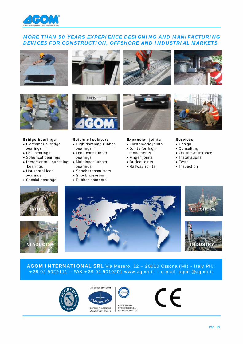
MORE THAN 50 YEARS EXPERIENCE DESIGNING AND MANIFACTURING DEVICES FOR CONSTRUCTION, OFFSHORE AND INDUSTRIAL MARKETS
Bridge bearings Elastomeric Bridge
bearings Pot bearings Spherical bearings Incremental Launching
bearings Horizontal load
bearings Special bearings
Seismic Isolators High damping rubber
bearings Lead core rubber
bearings Multilayer rubber
bearings Shock transmitters Shock absorber Rubber dampers
Expansion joints Elastomeric joints Joints for high
movements Finger joints Buried joints Railway joints
Services Design Consulting On site assistance Installations Tests Inspection
AGOM INTERNATIONAL SRL Via Mesero, 12 – 20010 Ossona (MI) - Italy PH.:+39 02 9029111 – FAX:+39 02 9010201 www.agom.it - e-mail: [email protected]
BRIDGES
VIADUCTS
OFFSHORE
INDUSTRY


![Bloodlust [Rev01]](https://img.pdfslide.us/doc/110x75/577cc6021a28aba7119d7bc9/bloodlust-rev01.jpg)