Embed Size (px)
Citation preview
Directional Control ValvesCatalog HY14-2502/US
A
2502-A1.p65, dd
A17 Parker Hannifin CorporationHydraulic Valve DivisionElyria, Ohio, USA
Specifications
Mounting Pattern NFPA D03, CETOP 3; NG 6Mounting DIN 24340-A6Interface ISO 4401-AB-03-4-A
CETOP R35H 4.2-4-03,NFPA D03
Maximum P, A, BPressure 345 Bar (5000 PSI) Standard
CSA 276 Bar (4000 PSI)
Tank:103 Bar (1500 PSI) Standard207 Bar (3000 PSI) Optionalwith H, FH, G, LG
CSA 103 Bar (1500 PSI)
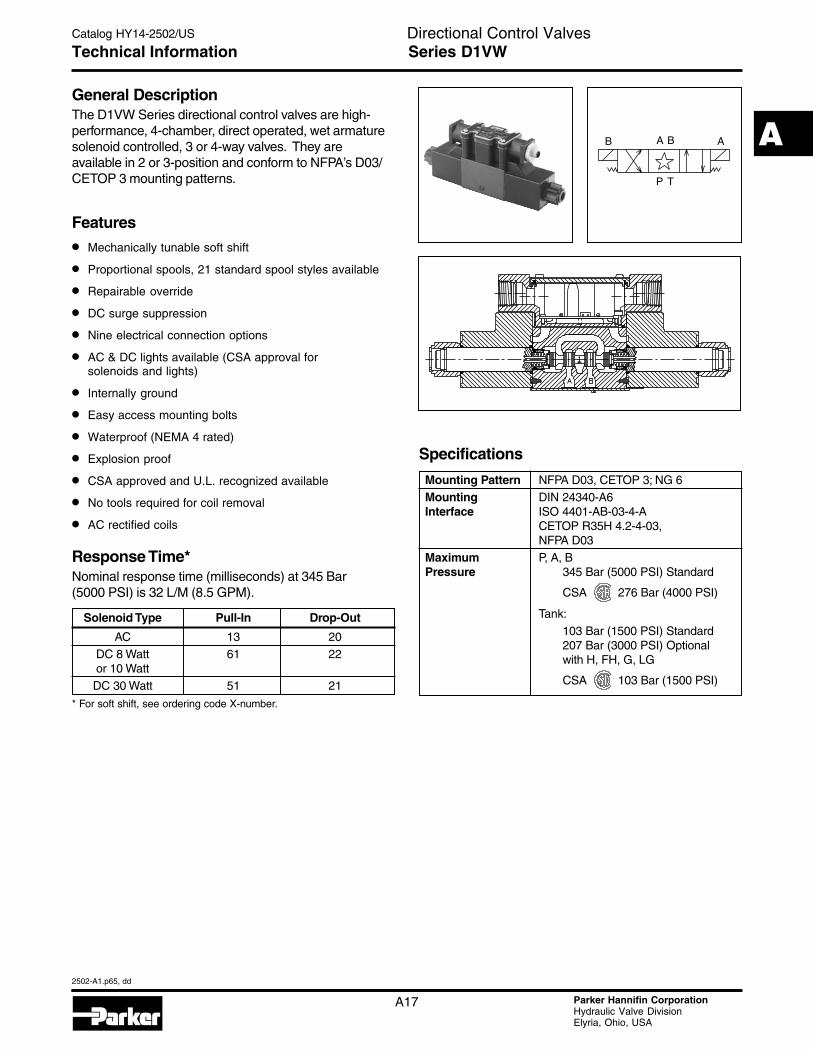
General DescriptionThe D1VW Series directional control valves are high-performance, 4-chamber, direct operated, wet armaturesolenoid controlled, 3 or 4-way valves. They areavailable in 2 or 3-position and conform to NFPA’s D03/CETOP 3 mounting patterns.
Features
• Mechanically tunable soft shift
• Proportional spools, 21 standard spool styles available
• Repairable override
• DC surge suppression
• Nine electrical connection options
• AC & DC lights available (CSA approval forsolenoids and lights)
• Internally ground
• Easy access mounting bolts
• Waterproof (NEMA 4 rated)
• Explosion proof
• CSA approved and U.L. recognized available
• No tools required for coil removal
• AC rectified coils
AA BB
P T
Response Time*Nominal response time (milliseconds) at 345 Bar(5000 PSI) is 32 L/M (8.5 GPM).
Solenoid Type Pull-In Drop-Out
AC 13 20DC 8 Watt 61 22or 10 WattDC 30 Watt 51 21
* For soft shift, see ordering code X-number.
Technical Information Series D1VW

Directional Control ValvesCatalog HY14-2502/US
A
2502-A1.p65, dd
A18 Parker Hannifin CorporationHydraulic Valve DivisionElyria, Ohio, USA
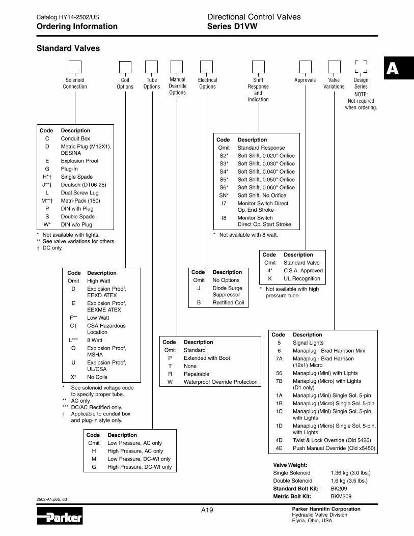
Ordering Information Series D1VW
Standard Valves
2MDNFPA D03CETOP 3DIN NG6
Code DescriptionN Nitrile
V Fluorocarbon
E * EPR
Code DescriptionA 24/50 VAC
D 120 VDC
G 198 VDC
J 24 VDC
K 12 VDC
L 6 VDC
N 220/50 VAC
Q 100/60 VAC
R 24/60 VAC
T 240/60 - 220/50 VAC
U 98 VDC
Y 120/60 - 110/50 VAC
Z 250 VDC
Code Description Symbol
B* 2 position, spring offset P to A
C 3 position, spring centered
D† 2 position, detent, P to A and B to T
E 2 position, spring centered and P to B
F 2 position, spring offset P to A and centered
H* 2 position, spring offset P to B
K 2 position, spring centered and P to A
M 2 position, spring offset P to B and centered
Code Symbol Code Symbol
001 014
002 015
003 016
004 020*
005 021
006 022
007 026*
008*, 030**009**
010 081
011 082
A B
P T
A B
P T
A B
P T
A B
P T
A B
P T
A B
P T
A B
P T
A B
P T
A B
P T
A B
P T
A B
P T
A B
P T
A B
P T
A B
P T
A B
P T
A B
P T
A B
P T
A B
P T
A B
P T
A B
P T
b
A B
P T
b a
A B
P T
b
A B
P T
b
A B
P T
b a
A B
P T
a
A B
P T
a
A B
P T
a
A B
P T
DDirectional
Control ValveBasic Valve Actuator# Spool Style Seal Solenoid
Voltage
1V
Code DescriptionW Solenoid, Wet Pin,
Screw-in
HW Reversed Wiring
* 008, 020 & 026 spools have closed crossover.** 009 & 030 spool have open crossover.See Universal Spool Chart for other spool options.
* Contact HVD foravailability.
# Valve schematic symbols are per NFPA/ANSIstandards, providing flow P to A whenenergizing solenoid A. Note operatorsreverse sides for #008 and #009 spools. Seeinstallation information for details. Toconfigure per DIN standards (A coil overA port, B coil over B port) code valves asD1VHW***.
* 020, 026 and 030 spools only.† 020 and 030 spools only.
Directional Control ValvesCatalog HY14-2502/US
A
2502-A1.p65, dd
A19 Parker Hannifin CorporationHydraulic Valve DivisionElyria, Ohio, USA
Code DescriptionOmit High Watt
D Explosion Proof,EEXD ATEX
E Explosion Proof,EEXME ATEX
F** Low Watt
C† CSA HazardousLocation
L*** 8 Watt
O Explosion Proof,MSHA
U Explosion Proof,UL/CSA
X* No Coils
Valve Weight:Single Solenoid 1.36 kg (3.0 lbs.)
Double Solenoid 1.6 kg (3.5 lbs.)
Standard Bolt Kit: BK209Metric Bolt Kit: BKM209
Standard Valves
SolenoidConnection
TubeOptions
Approvals DesignSeriesNOTE:
Not requiredwhen ordering.
ManualOverrideOptions
Code DescriptionOmit Standard
P Extended with Boot
T None
R Repairable
W Waterproof Override Protection
Code DescriptionOmit Low Pressure, AC only
H High Pressure, AC only
M Low Pressure, DC-WI only
G High Pressure, DC-WI only
CoilOptions
ElectricalOptions
Code DescriptionOmit No Options
J Diode SurgeSuppressor
B Rectified Coil
ValveVariations
ShiftResponse
andIndication
* See solenoid voltage codeto specify proper tube.
** AC only.*** DC/AC Rectified only.† Applicable to conduit box
and plug-in style only.
Code Description5 Signal Lights
6 Manaplug - Brad Harrison Mini
7A Manaplug - Brad Harrison(12x1) Micro
56 Manaplug (Mini) with Lights
7B Manaplug (Micro) with Lights(D1 only)
1A Manaplug (Mini) Single Sol. 5-pin
1B Manaplug (Micro) Single Sol. 5-pin
1C Manaplug (Mini) Single Sol. 5-pin,with Lights
1D Manaplug (Micro) Single Sol. 5-pin,with Lights
4D Twist & Lock Override (Old 5426)
4E Push Manual Override (Old x5450)
Code DescriptionOmit Standard Valve
4* C.S.A. Approved
K UL Recognition
Code DescriptionC Conduit Box
D Metric Plug (M12X1),DESINA
E Explosion Proof
G Plug-In
H*† Single Spade
J**† Deutsch (DT06-25)
L Dual Screw Lug
M**† Metri-Pack (150)
P DIN with Plug
S Double Spade
W* DIN w/o Plug
* Not available with lights.** See valve variations for others.† DC only.
Code DescriptionOmit Standard Response
S2* Soft Shift, 0.020" Orifice
S3* Soft Shift, 0.030" Orifice
S4* Soft Shift, 0.040" Orifice
S5* Soft Shift, 0.050" Orifice
S6* Soft Shift, 0.060" Orifice
SN* Soft Shift, No Orifice
I7 Monitor Switch DirectOp. End Stroke
I8 Monitor SwitchDirect Op. Start Stroke
Ordering Information Series D1VW
* Not available with 8 watt.
* Not available with highpressure tube.

Directional Control ValvesCatalog HY14-2502/US
A
2502-A1.p65, dd
A20 Parker Hannifin CorporationHydraulic Valve DivisionElyria, Ohio, USA
Solenoid RatingsInsulation System Class F
Allowable Deviation -10% to +15% for DC and AC rectified coilsfrom rated voltage -5% to +5% for AC Coils
Armature Wet pin type
CSA File Number LR60407
Environmental DC Solenoids are rated at NEMA 4 (IP67)Capability or better when properly wired and installed.
Contact HVD for AC coil applications.
Explosion Proof Solenoid Ratings*U.L. & CSA (EU) Class I, Div 1 & 2, Groups C & D
Class II, Div 1 & 2, Groups E, F & GAs defined by the NEC
M.S.H.A. (EO) Complies with 30CFR, Part 18
ATEX (ED) Complies with ATEX requirements for:Exd, Group IIB; EN50014: 1999+ Amds.1 & 2, EN50018: 2000
CSA Hazardous Location Class II, Groups E, F & G
Technical Information Series D1VW
* Allowable Voltage Deviation +/- 10%Note that AC coils are single frequency only.
Voltage In Rush Amps In Rush Amps Holding Amps Watts ResistanceVoltage Code Power Code Amperage D1VW VA @ 3MM D1VW D1VW D1VW
A 24/50 VAC, High Watt 7.00 Amps 168 VA 2.65 Amps 28 W 1.67 ohm(s)D L 120 VDC N/A N/A 0.09 Amps 10 W 1584.00 ohm(s)
N/A N/A 0.26 Amps 30 W 528.00 ohm(s)E 24/60 VAC, High Watt 6.00 Amps 144 VA 1.85 Amps 20 W 1.67 ohm(s)
24/50 VAC, High Watt 7.00 Amps 168 VA 2.65 Amps 28 W 1.67 ohm(s)G L 198 VDC N/A N/A 0.05 Amps 10 W 3920.40 ohm(s)
N/A N/A 0.15 Amps 30 W 1306.80 ohm(s)J L 24 VDC N/A N/A 0.44 Amps 10 W 51.89 ohm(s)
N/A N/A 1.32 Amps 30 W 17.27 ohm(s)K L 12 VDC N/A N/A 0.88 Amps 10 W 12.97 ohm(s)
N/A N/A 2.64 Amps 30 W 4.32 ohm(s)L L 6 VDC N/A N/A 1.67 Amps 10 W 3.59 ohm(s)
N/A N/A 5.00 Amps 30 W 1.20 ohm(s)M L 9 VDC N/A N/A 1.11 Amps 10 W 8.12 ohm(s)
N/A N/A 3.35 Amps 30 W 2.67 ohm(s)P 110/50 VAC 0.38 Amps 19 W 135.00 ohm(s)R 24/60 VAC, High Watt 8.00 Amps 192 VA 2.70 Amps 27 W 1.40 ohm(s)
F 24/60 VAC, Low Watt 6.67 Amps 160 VA 2.20 Amps 23 W 1.52 ohm(s)S ***Specials*** SEE BELOWT 240/60 VAC, High Watt 0.77 Amps 185 VA 0.26 Amps 25 W 134.50 ohm(s)
220/50 VAC, High Watt 0.82 Amps 180 VA 0.31 Amps 27 W 134.50 ohm(s)F 240/60 VAC, Low Watt 0.70 Amps 168 VA 0.22 Amps 21 W 145.00 ohm(s)F 220/50 VAC, Low Watt 0.75 Amps 165 VA 0.26 Amps 23 W 145.00 ohm(s)
U L 98 VDC N/A N/A 0.10 Amps 10 W 960.00 ohm(s)X L 16 VDC N/A N/A 0.63 Amps 10 W 25.60 ohm(s)Y 120/60 VAC, High Watt 1.55 Amps 186 VA 0.49 Amps 25 W 33.70 ohm(s)
110/50 VAC, High Watt 1.65 Amps 182 VA 0.58 Amps 27 W 33.70 ohm(s)F 120/60 VAC, Low Watt 1.40 Amps 168 VA 0.42 Amps 21 W 36.50 ohm(s)F 110/50 VAC, Low Watt 1.50 Amps 165 VA 0.50 Amps 23 W 36.50 ohm(s)
L*B 120/60 VAC, 10 Watt 0.63 Amps 83 VA 0.18 Amps 10 W 75.00 ohm(s)L*B 110/50 VAC, 10 Watt 0.73 Amps 79 VA 0.20 Amps 10 W 75.00 ohm(s)*H 120/60 VAC, High Pressure 1.40 Amps 168 VA 0.50 Amps 26 W 36.50 ohm(s)*H 110/50 VAC, High Pressure 1.48 Amps 163 VA 0.60 Amps 28 W 36.50 ohm(s)
Z L 250 VDC N/A N/A 0.04 Amps 10 W 6875.00 ohm(s)N/A N/A 0.13 Amps 30 W 1889.64 ohm(s)
Specials S Other voltages/frequencies may be available Contact HVD for more informationExplosion Proof Solenoids
R 24/60 VAC 7.63 Amps 183 VA 2.85 Amps 27 W 1.99 ohm(s)T 240/60 VAC 0.76 Amps 183 VA 0.29 Amps 27 W 1.34 ohm(s)N 220/50 VAC 0.77 Amps 169 VA 0.31 Amps 27 W 1.38 ohm(s)Y 120/60 VAC 1.60 Amps 192 VA 0.58 Amps 27 W 33.50 ohm(s)P 110/50 VAC 1.47 Amps 162 VA 0.57 Amps 27 W 34.70 ohm(s)Q 100/60 VAC 1.90 Amps 192 VA 0.70 Amps 27 W 38.60 ohm(s)K 12 VDC N/A N/A 2.75 Amps 33 W 4.36 ohm(s)J 24 VDC N/A N/A 1.38 Amps 33 W 17.33 ohm(s)D 120 VDC N/A N/A 0.28 Amps 33 W 420.92 ohm(s)Z 250 VDC N/A N/A 0.13 Amps 33 W 1952.66 ohm(s)
Code

Directional Control ValvesCatalog HY14-2502/US
A
2502-A1.p65, dd
A21 Parker Hannifin CorporationHydraulic Valve DivisionElyria, Ohio, USA
Dimensions Series D1VW
Plug-In Box, Double DC Solenoid
Plug-In Box, Single DC Solenoid
Inch equivalents for millimeter dimensions are shown in (**)
143.7(5.66)87.8
(3.46)44.9
(1.77)
244.4(9.62)
66.0(2.60) 50.0
(1.97)
93.2(3.67)
15.5(0.61)
24.8(0.98)
49.6(1.95)
46.0(1.81)
23.8(0.94)
ManualOverride
Min. CoilRemoval
1/2 NPTF Thd.Both Ends
54.3(2.14)
87.8(3.46)
44.9(1.77)
188.5(7.42)
66.0(2.60) 50.0
(1.97)
93.2(3.67)
15.5(0.61)
24.8(0.98)
49.6(1.95)
46.0(1.81)
23.8(0.94)
1/2 NPTF Thd.Both Ends
Min. CoilRemoval
54.3(2.14)
Directional Control ValvesCatalog HY14-2502/US
A
2502-A1.p65, dd
A22 Parker Hannifin CorporationHydraulic Valve DivisionElyria, Ohio, USA
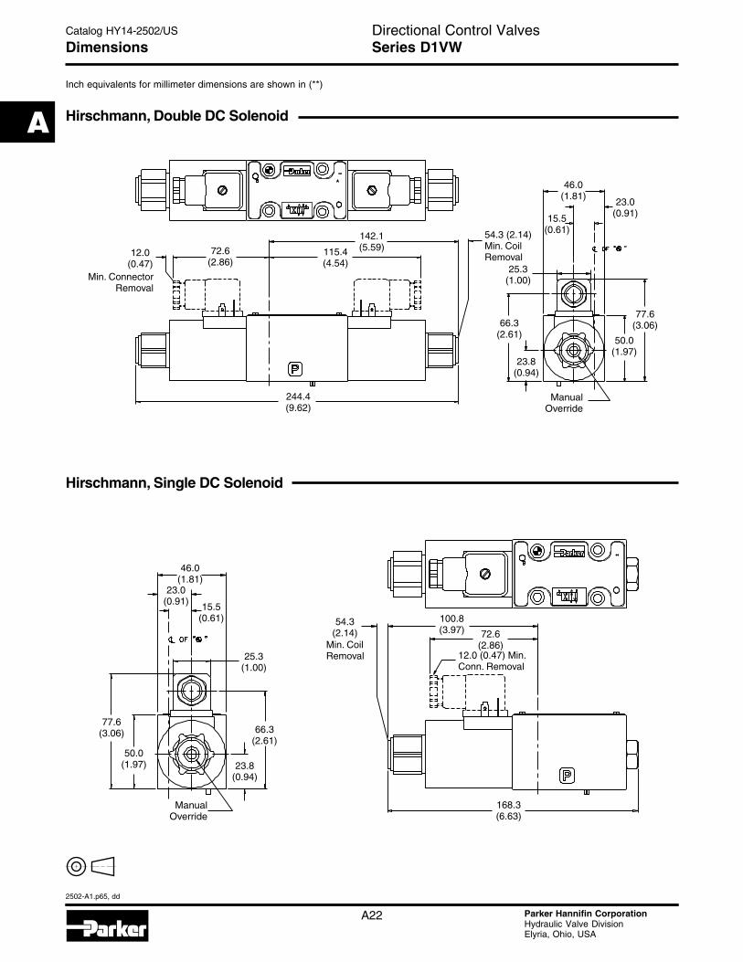
Dimensions Series D1VW
Hirschmann, Double DC Solenoid
Hirschmann, Single DC Solenoid
Inch equivalents for millimeter dimensions are shown in (**)
142.1(5.59)115.4
(4.54)72.6
(2.86)
244.4(9.62)
66.3(2.61)
50.0(1.97)
77.6(3.06)
15.5(0.61)
23.0(0.91)
46.0(1.81)
25.3(1.00)
ManualOverride
ConnectorRemoval
Min.
23.8(0.94)
12.0(0.47)
54.3 (2.14)Min. CoilRemoval
77.6(3.06) 66.3
(2.61)50.0
(1.97)
72.6(2.86)
168.3(6.63)
100.8(3.97)
15.5(0.61)
46.0(1.81)
25.3(1.00)
23.0(0.91)
ManualOverride
12.0 (0.47) Min.Conn. Removal
23.8(0.94)
Min. CoilRemoval
54.3(2.14)
Directional Control ValvesCatalog HY14-2502/US
A
2502-A1.p65, dd
A23 Parker Hannifin CorporationHydraulic Valve DivisionElyria, Ohio, USA
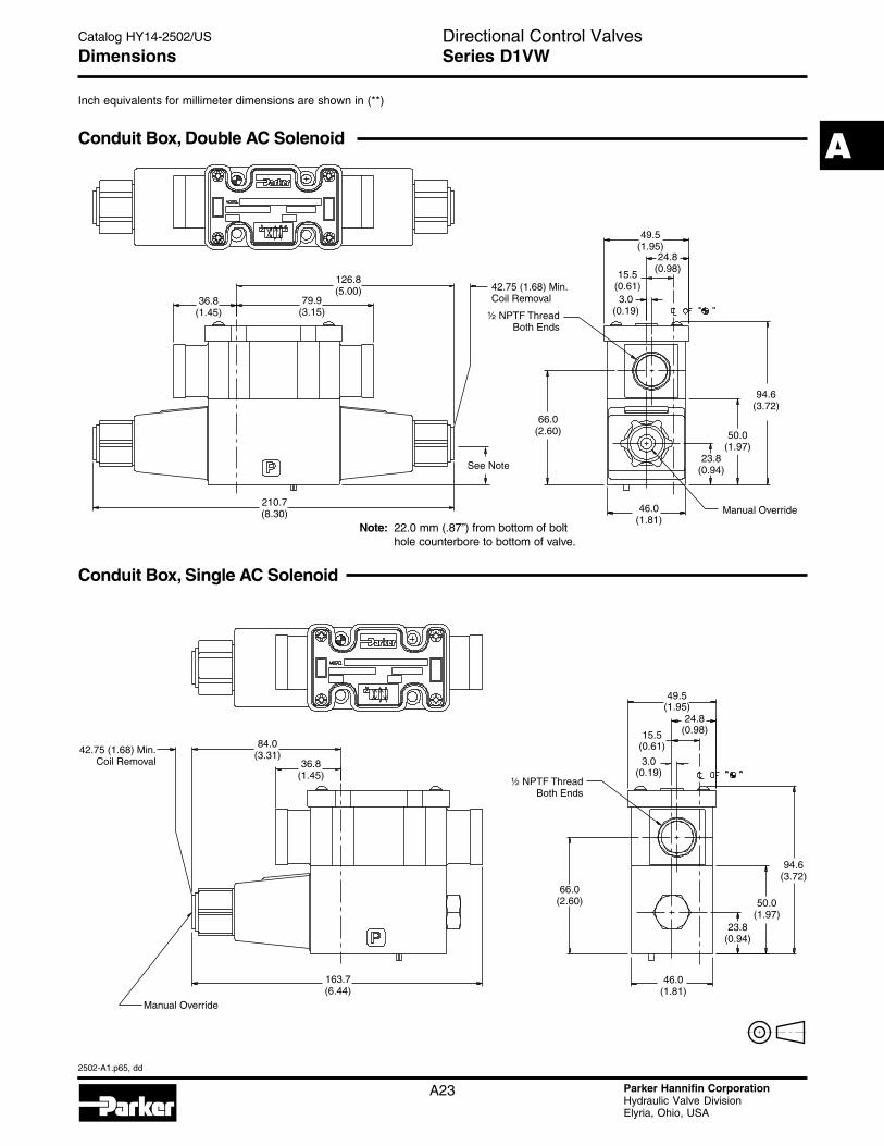
Dimensions Series D1VW
Conduit Box, Double AC Solenoid
Conduit Box, Single AC Solenoid
Inch equivalents for millimeter dimensions are shown in (**)
Note: 22.0 mm (.87”) from bottom of bolthole counterbore to bottom of valve.
126.8(5.00)
79.9(3.15)
36.8(1.45)
42.75 (1.68) Min.Coil Removal
½ NPTF ThreadBoth Ends
66.0(2.60)
46.0(1.81)
Manual Override
94.6(3.72)
50.0(1.97)
210.7(8.30)
49.5(1.95)
24.8(0.98)
15.5(0.61)3.0
(0.19)
23.8(0.94)See Note
42.75 (1.68) Min.Coil Removal
84.0(3.31)
36.8(1.45)
Manual Override
163.7(6.44)
66.0(2.60)
46.0(1.81)
23.8(0.94)
50.0(1.97)
94.6(3.72)
½ NPTF ThreadBoth Ends
49.5(1.95)
24.8(0.98)15.5
(0.61)
3.0(0.19)
Directional Control ValvesCatalog HY14-2502/US
A
2502-A1.p65, dd
A24 Parker Hannifin CorporationHydraulic Valve DivisionElyria, Ohio, USA
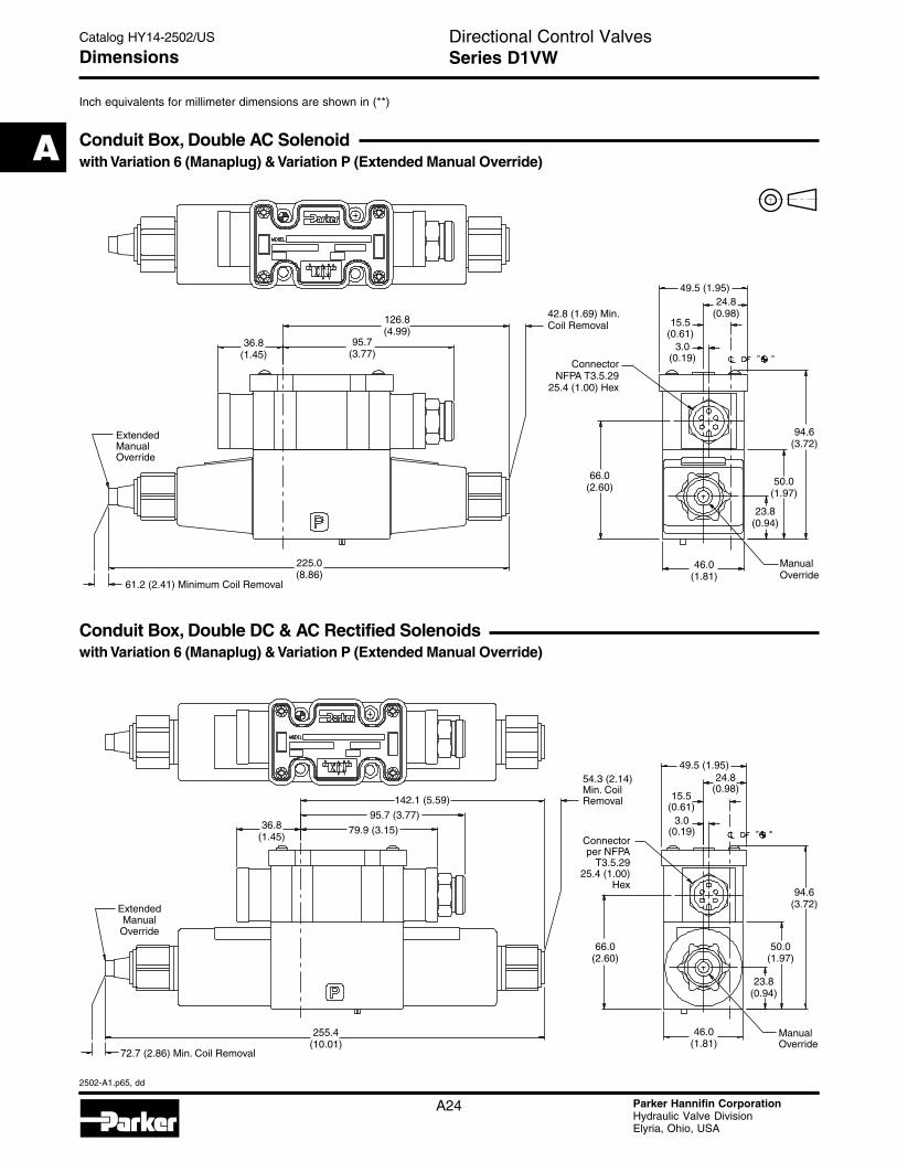
Dimensions Series D1VW
Conduit Box, Double AC Solenoidwith Variation 6 (Manaplug) & Variation P (Extended Manual Override)
Conduit Box, Double DC & AC Rectified Solenoidswith Variation 6 (Manaplug) & Variation P (Extended Manual Override)
Inch equivalents for millimeter dimensions are shown in (**)
ExtendedManualOverride
61.2 (2.41) Minimum Coil Removal
225.0(8.86)
36.8(1.45)
126.8(4.99)
95.7(3.77)
42.8 (1.69) Min.Coil Removal
ConnectorNFPA T3.5.29
25.4 (1.00) Hex
94.6(3.72)
50.0(1.97)
23.8(0.94)
ManualOverride
46.0(1.81)
66.0(2.60)
15.5(0.61)
3.0(0.19)
49.5 (1.95)24.8
(0.98)
ExtendedManualOverride
36.8(1.45)
95.7 (3.77)
79.9 (3.15)
142.1 (5.59)
Connectorper NFPA
T3.5.2925.4 (1.00)
Hex
15.5(0.61)
3.0(0.19)
49.5 (1.95)24.8
(0.98)54.3 (2.14)Min. CoilRemoval
ManualOverride
46.0(1.81)
50.0(1.97)
23.8(0.94)
94.6(3.72)
66.0(2.60)
72.7 (2.86) Min. Coil Removal
255.4(10.01)
Directional Control ValvesCatalog HY14-2502/US
A
2502-A1.p65, dd
A25 Parker Hannifin CorporationHydraulic Valve DivisionElyria, Ohio, USA
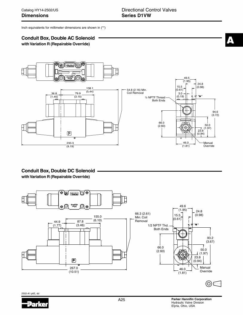
Dimensions Series D1VW
Conduit Box, Double AC Solenoidwith Variation R (Repairable Override)
Conduit Box, Double DC Solenoidwith Variation R (Repairable Override)
Inch equivalents for millimeter dimensions are shown in (**)
44.9(1.77)
66.3 (2.61)Min. CoilRemoval87.8
(3.46)
267.0(10.51)
155.0(6.10)
ManualOverride
66.0(2.60) 50.0
(1.97)
93.2(3.67)
15.5(0.61)
24.8(0.98)
49.6(1.95)
46.0(1.81)
23.8(0.94)
1/2 NPTF Thd.Both Ends
233.3(9.19)
138.1(5.44)
79.9(3.15)
36.8(1.45)
54.8 (2.16) Min.Coil Removal
½ NPTF ThreadBoth Ends
66.0(2.60)
46.0(1.81)
50.0(1.97)
94.6(3.72)
ManualOverride
23.8(0.94)
49.5(1.95)
24.8(0.98)15.5
(0.61)3.0
(0.19)

Directional Control ValvesCatalog HY14-2502/US
A
2502-A1.p65, dd
A26 Parker Hannifin CorporationHydraulic Valve DivisionElyria, Ohio, USA
Dimensions Series D1VW
DESINA, Double DC Solenoid
Inch equivalents for millimeter dimensions are shown in (**)
142.1(5.59)
242.4(9.54)
48.0(1.89)
46.0(1.81)
50.8(2.00)
70.3(2.77)
90.7(3.57)
15.5(0.61)
23.8(0.94)
Manual Override
54.3 (2.14)Min. CoilRemoval
142.1(5.59)
167.3(6.59)
46.0(1.81)
50.8(2.00)
70.3(2.77)
90.7(3.57)
15.5(0.61)
23.8(0.94)
Manual Override
543 (2.14)Min. CoilRemoval
DESINA, Single DC Solenoid

Directional Control ValvesCatalog HY14-2502/US
A
2502-A1.p65, dd
A27 Parker Hannifin CorporationHydraulic Valve DivisionElyria, Ohio, USA
Dimensions Series D1VW
Explosion Proof U.L. & C.S.A., Double Solenoid
Explosion Proof M.S.H.A., Double Solenoid
Explosion Proof ATEX, Double Solenoid
Inch equivalents for millimeter dimensions are shown in (**)
163.7(6.44)60.4
(2.38)
130.8(5.15)
304.4(11.98)
94.4(3.72)
18 Inch LeadWires Standard
73.0 (2.87)
46.0(1.81)
7.5 (0.30)
15.1 (0.61)
1/2" NPT
163.7(6.44)60.4
(2.38)
130.8(5.15)
304.4(6.44)
3/4-20 UNFThd. 3/4-20 UNF
Thd. 38.0 (1.50)
113.0(4.45)
15.51 (0.61)
7.5 (0.30)46.0
(1.81)73.0 (2.87)
74.7 (2.94)
69.9 (2.75)19.4
(0.76) 15.5(0.61)
M20 x 1.5-6H Thd.
100.9(3.97)
42.8(1.69)
131.7(5.19)
100.6(3.96)
7.5 (0.30)46.0 (1.81)
73.5 (2.89)
141.0 (5.55)
324.7 (12.78)

Directional Control ValvesCatalog HY14-2502/US
A
2502-A1.p65, dd
A28 Parker Hannifin CorporationHydraulic Valve DivisionElyria, Ohio, USA
Dimensions Series D1VW
Conduit Box, Single DC Solenoidwith Variation I7 (Monitor Switch) & Variation P (Extended Manual Override)
Inch equivalents for millimeter dimensions are shown in (**)
Monitor Switch(valve variation I7)
This feature provides for electrical confirmation of thespool shift. This can be used in safety circuits, to assureproper sequencing, etc.
Switch DataInductive switch requiring +18-42 volt input. Outputs Aand B are opposite; one at “0” voltage, the other at inputvoltage. During switching, A and B outputs reverse.Provides 0.4A switching current.
For repetitive switch power-up conditions, please consultfactory.
12.0 (0.47) Min.Conn. Removal
115.1(4.53)
274.9(10.82)
ExtendedManual
Override
72.7(2.86)
70.6(2.78)
81.9(3.22)
94.6(3.72)
3.0(0.12)
15.5(0.61)
49.5(1.95)
46.0(1.81)
50.0(1.97)
24.8(0.98)
23.8(0.94)
Min.Coil Removal
B
Block Diagram
Inductor
Regulator
Pin 1(Input 24VDC)
Pin 4(Ground Terminal)
Pin 2(Output – Normally Open)
Pin 3(Output – Normally Closed)
(Extended, or Energized Position)

Directional Control ValvesCatalog HY14-2502/US
A
2502-A1.p65, dd
A29 Parker Hannifin CorporationHydraulic Valve DivisionElyria, Ohio, USA
Accessories Series D1VW
Conduit Box(connection option G & C)
Interface – 152.4 cm (6.0 inch) lead wires, 18 awg.
– Waterproof
Plug-In Conduit Box
– NEMA 4 rated
– Phoenix connector
– Lights, Manaplug available
Manaplug(valve variations 6, 56, 630)
Interface – Brad Harrison Plug
– 3-Pin for Single Solenoid
– 5-Pin for Double Solenoid
Signal Lights(valve variation 5)
Interface – LED
Solenoid (Positive)Wire #2 (Red/White)
GroundWire #1 (Green)
Solenoid (Negative)Wire #3 (Red/Black)
3-Pin Manaplug (Mini) with LightsSingle Solenoid Valves
"B” Solenoid (Positive)Wire #1 (Red/White)
"A” Solenoid (Negative)Wire #2 (Red)
"B” Solenoid (Negative)Wire #5 (Red/Black)
"A” Solenoid (Positive)Wire #4 (Red/Yellow)
GroundWire #3 (Green)
5-Pin Manaplug (Mini) with LightsSingle and Double Solenoid Valves
("A" and "B" Solenoids Reversed for #8 and #9 Spools)
Pin #2(Negative)
Pin #3(Ground)
Pin #1(Positive)
Hirschmann Plug with LightsISO 4400/DIN 43650 Form “A”
Face View of Plug
Micro Connectorvalve variations 7A, 7B
DESINA ConnectorM12 pin assignmentStandard
DESINA – designPin 1 and 2connected1 = Not used
2 = Not used
3 = 0V
4 = Signal(24 V)
5 = Earth Ground
Solenoid (Negative)Wire /3 (Blue)
Solenoid (Positive)Wire /4 (Black)
GroundWire /1 (Brown)
GroundWire /5 (Gray)
"A" Solenoid (Negative)Wire /3 (Blue)
"B" Solenoid (Negative)Wire /1 (Brown)
"A" Solenoid (Positive)Wire /4 (Black)
"B" Solenoid (Positive)Wire /2 (White)
Directional Control ValvesCatalog HY14-2502/US
A
2502-A1.p65, dd
A38 Parker Hannifin CorporationHydraulic Valve DivisionElyria, Ohio, USA
Accessories Series D1V
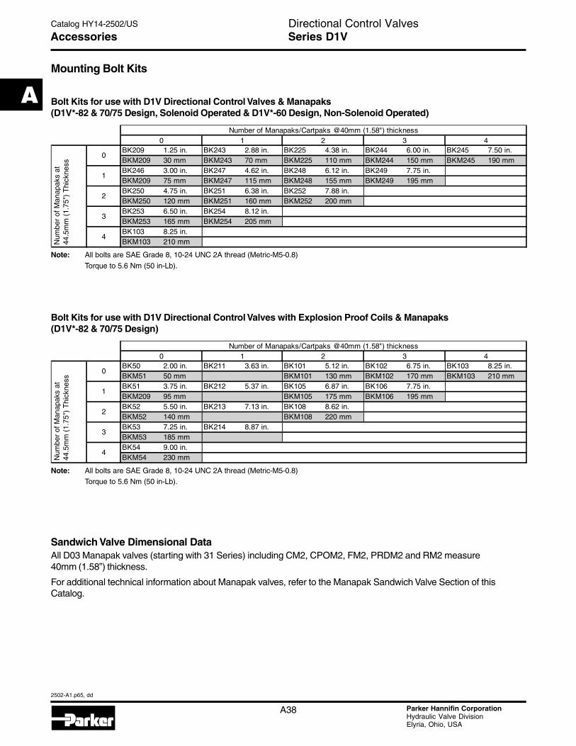
Mounting Bolt Kits
Sandwich Valve Dimensional DataAll D03 Manapak valves (starting with 31 Series) including CM2, CPOM2, FM2, PRDM2 and RM2 measure40mm (1.58”) thickness.
For additional technical information about Manapak valves, refer to the Manapak Sandwich Valve Section of thisCatalog.
Bolt Kits for use with D1V Directional Control Valves & Manapaks(D1V*-82 & 70/75 Design, Solenoid Operated & D1V*-60 Design, Non-Solenoid Operated)
Bolt Kits for use with D1V Directional Control Valves with Explosion Proof Coils & Manapaks(D1V*-82 & 70/75 Design)
Note: All bolts are SAE Grade 8, 10-24 UNC 2A thread (Metric-M5-0.8)
Torque to 5.6 Nm (50 in-Lb).
Note: All bolts are SAE Grade 8, 10-24 UNC 2A thread (Metric-M5-0.8)Torque to 5.6 Nm (50 in-Lb).
BK209 1.25 in. BK243 2.88 in. BK225 4.38 in. BK244 6.00 in. BK245 7.50 in.BKM209 30 mm BKM243 70 mm BKM225 110 mm BKM244 150 mm BKM245 190 mmBK246 3.00 in. BK247 4.62 in. BK248 6.12 in. BK249 7.75 in.BKM209 75 mm BKM247 115 mm BKM248 155 mm BKM249 195 mmBK250 4.75 in. BK251 6.38 in. BK252 7.88 in.BKM250 120 mm BKM251 160 mm BKM252 200 mmBK253 6.50 in. BK254 8.12 in.BKM253 165 mm BKM254 205 mmBK103 8.25 in.BKM103 210 mm
2 3 4
0
1
2
Number of Manapaks/Cartpaks @40mm (1.58") thickness
Num
ber
of M
anap
aks
at
44.5
mm
(1.
75")
Thi
ckne
ss
0 1
3
4
BK50 2.00 in. BK211 3.63 in. BK101 5.12 in. BK102 6.75 in. BK103 8.25 in.BKM51 50 mm BKM101 130 mm BKM102 170 mm BKM103 210 mmBK51 3.75 in. BK212 5.37 in. BK105 6.87 in. BK106 7.75 in.BKM209 95 mm BKM105 175 mm BKM106 195 mmBK52 5.50 in. BK213 7.13 in. BK108 8.62 in.BKM52 140 mm BKM108 220 mmBK53 7.25 in. BK214 8.87 in.BKM53 185 mmBK54 9.00 in.BKM54 230 mm
Number of Manapaks/Cartpaks @40mm (1.58") thickness40 1 2 3
Num
ber
of M
anap
aks
at
44.5
mm
(1.
75")
Thi
ckne
ss
0
1
2
3
4

Directional Control ValvesCatalog HY14-2502/US
A
2502-A1.p65, dd
A39 Parker Hannifin CorporationHydraulic Valve DivisionElyria, Ohio, USA
Fluid RecommendationsPremium quality hydraulic oil with a viscosity rangebetween 150-250 SSU (32 -54 cst) at 38°C (100°F) isrecommended. The absolute operation viscosity rangeis from 80-1000 SSU (16-220 cst). Oil should havemaximum anti-wear properties and rust and oxidationtreatments.
Fluids and SealsValves using synthetic, fire-resistant fluids requirespecial seals. When phosphate ester or its blends areused, FLUOROCARBON seals are required. Water-glycol, water-in-oil emulsions, and petroleum oil maybe used with NITRILE seals.
Temperature RecommendationRecommended oil temperature:-7° to +71°C (-20 to +160°F)
FiltrationFor maximum valve and system component life, thesystem should be protected at a contamination levelnot to exceed 125 particles greater than 10 micronsper milliliter of fluid. (SAE Class 4 or better, ISO Code16/13).
Tank Line SurgesIf several valves are piped with a common tank line,flow surges in the line may cause unexpected spoolshift. Detent style valves are most susceptible to this.Separate tank lines should be used when line surgesare expected in an application.
Recommended Mounting Position
Valve Type Recommended Mounting Position
Detent (Solenoid) HorizontalSpring Centered UnrestrictedSpring Offset Unrestricted
SiltingSilting can cause any sliding spool valve to stick andnot spring return, if held shifted under pressure forlong periods of time. The valve should be cycledperiodically to prevent sticking.
Single Pass OperationValve flow ratings are for double pass operation(with equal flow in both paths). When using thesecomponents in single pass applications, flowcapabilities may be reduced. Consult your local Parkerrepresentative for details.
Flow Path Data
*Note: On valves with 008 or 009 spool, A and/or B operatorsreverse sides. Flow paths remain the same as viewed fromtop of valve.
Double Solenoid. With solenoid “A” energized, flowpath is P→A and B→T. When solenoid “B” isenergized, flow path is P→B and A→T. The centercondition on a spring-centered valve exists when bothcoils are de-energized, or during a complete shift, asthe spool passes through center.
Detent and Spring Offset. The center condition existson detent and spring offset valves only during spoolcrossover. To shift and hold a detented spool, only amomentary energizing of the solenoid is necessary.The minimum duration of the signal is approximately0.1 seconds for DC voltages. This position will be heldprovided the spool center line is in a horizontal plane,and no shock or vibration is present to displace thespool.
Single Solenoid. Spring offset valves can be orderedin styles B, E, F, H, K and M. Flow path data for thevarious styles are described in the order chart.
Electrical FailureShould electric power fail, spring offset and springcentered valves will shift to the spring held position.Detented valves will stay in the last position heldbefore power failure. If main flow does not fail or stopsimultaneously, machine actuators may continue tofunction in an undesirable manner or sequence.
Torque SpecificationsTorque values recommended for the bolts which mountthe valve to the manifold or subplate are as follows:
#10-24 thread (M5-0.8) torque 5.6 Nm (50 in-lbs).
D1V
Operator A Operator B
T
B AP
Locating pin
Series D1VInstallation Information