Embed Size (px)
Citation preview
Industrial Hydraulic Valves
Catalog HY14-2500/US
Directional Control, Pressure Control, Sandwich, Subplates & Manifolds, Accessories
Return to ALPHA TOC
Return to SECTION
TOC

Parker Hannifin CorporatioHydraulic Valve DivisionElyria, Ohio, USA
Cat HY14-2500-frtcvr.indd, dd
II
Industrial Hydraulic ValvesCatalog HY14-2500/US
FAILURE OR IMPROPER SELECTION OR IMPROPER USE OF THE PRODUCTS DESCRIBED HEREIN OR RELATED ITEMS CAN CAUSE DEATH, PERSONAL INJURY AND PROPERTY DAMAGE.
• This document and other information from Parker-Hannifin Corporation, its subsidiaries and authorized distributors provide product or system options for further investigation by users having technical expertise.
• The user, through its own analysis and testing, is solely responsible for making the final selection of the system and components and assuring that all performance, endurance, maintenance, safety and warning requirements of the application are met. The user must analyze all aspects of the application, follow applicable industry standards, and follow the information concerning the product in the current product catalog and in any other materials provided from Parker or its subsidiaries or authorized distributors.
• To the extent that Parker or its subsidiaries or authorized distributors provide component or system options based upon data or specifications provided by the user, the user is responsible for determining that such data and specifications are suitable and sufficient for all applications and reasonably foreseeable uses of the components or systems.
WARNING – USER RESPONSIBILITY
The items described in this document are hereby offered for sale by Parker-Hannifin Corporation, its subsidiaries or its authorized distributors. This offer and its acceptance are governed by the provisions stated in the detailed “Offer of Sale” elsewhere in this document or available at www.parker.com/hydraulicvalve.
© Copyright 2011 Parker Hannifin Corporation, All Rights Reserved
OFFER OF SALE
For safety information, see Safety Guide SG HY14-1000 at www.parker.com/safety or call 1-800-CParker.
SAFETY GUIDE
Return to SECTION
TOC
Return to ALPHA TOC

2F1C.indd, dd
E1 Parker Hannifin CorporatioHydraulic Valve DivisionElyria, Ohio, USA
Catalog HY14-2500/US Flow Control and Check Valves
E
Return to ALPHA TOC
Return toSECTION
TOCSeries 2F1CGeneral Description ............................ 2-Way Flow Control Valves, Subplate Mounted ................................. E2
Operation ........................................................................................................................................................ E2 Features ......................................................................................................................................................... E2
Ordering Information ...................................................................................................................................... E2 Specifications ................................................................................................................................................. E3
Performance Curves ............................................................................................................................... E4 - E6 Dimensions ..................................................................................................................................................... E7
Series C4VGeneral Description ............................ Direct Operated Check Valves, Subplate Mounted ............................ E8
Operation ........................................................................................................................................................ E8 Features ......................................................................................................................................................... E8
Ordering Information ...................................................................................................................................... E8 Specifications ................................................................................................................................................. E9
Performance Curves ....................................................................................................................................... E9 Dimensions ................................................................................................................................................... E10
Series C4VGeneral Description ........................... Pilot Operated Check Valves, Subplate Mounted ............................ E12
Operation ...................................................................................................................................................... E12 Features ....................................................................................................................................................... E12
Ordering Information .................................................................................................................................... E12 Specifications ............................................................................................................................................... E13
Performance Curves ..................................................................................................................................... E13 Dimensions ................................................................................................................................................... E14
Series C5PGeneral Description ............................ Pilot Operated Check Valves, SAE Flange ...................................... E15
Operation ...................................................................................................................................................... E15 Features ....................................................................................................................................................... E15
Ordering Information .................................................................................................................................... E15 Specifications ............................................................................................................................................... E16
Performance Curves ..................................................................................................................................... E16 Dimensions ................................................................................................................................................... E17
Series C5VGeneral Description ............................ Direct Operated Check Valves, SAE Flange .................................... E18
Operation ...................................................................................................................................................... E18 Features ....................................................................................................................................................... E18
Ordering Information .................................................................................................................................... E18 Specifications ............................................................................................................................................... E19
Performance Curves ..................................................................................................................................... E19 Dimensions ................................................................................................................................................... E20
Terms of Sale and Warranty Limitations .......................................................................................................... E21
Safety Guide ...............................................................................................................................................E22 - E23
Contents
2F1C.indd, dd
E2 Parker Hannifin CorporatioHydraulic Valve DivisionElyria, Ohio, USA
Pressure Compensated Flow Control ValvesCatalog HY14-2500/US
Series 2F1C
E
Return to SECTION
TOC
Return to ALPHA TOC
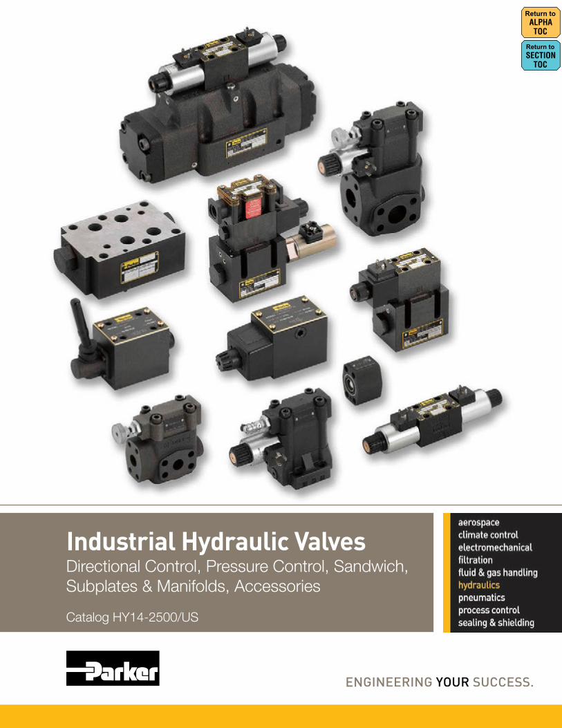
General DescriptionSeries 2F1C 2-way flow control valves provide pres-sure and viscosity compensated flow from port A to port B. The counter direction is blocked (standard) or can be open via an integral reverse flow check valve (optional).
OperationThe compensator spool is located in front of the meter-ing spool. The metering spool is closed in the neutral position to avoid undesired initial actuator motion. The oil flow to open the metering spool has to pass a needle valve (not shown in the sectional drawing). The needle valve can be adjusted from the front panel to set the response time of the 2F1C.
The metering spool is adjusted by the main control knob. The key lock has three positions:
Lock: Adjustment is locked.
Adjust: Full adjustment is permitted.
Trim: Fine adjustment of ±5% is possible.
Features• 2 way flow control valve.
• Subplate mounting according to ISO 6263.
• Excellent fine adjustment.
• Adjustable response time.
• Closed in neutral position.
• Optional reverse flow check valve.
• 2 sizes: NG10 (3/8"), NG16 (3/4").
Technical Information
Weight:2F1C02 6.0 kg (13.2 lbs.)
2F1C03 9.0 kg (19.8 lbs.)
2-Way Flow Control Valve
Size Adjustment Knob with
Lock
Design Series
Options Check with
Factory
2F1C
Code Description 02 NG10 (3/8")
03 NG16 (3/4")
Code Description 0 Without Check
C With Check
Seal
01 B
Fluorocarbon
Reverse Flow Check
5
Ordering Information

2F1C.indd, dd
E3 Parker Hannifin CorporatioHydraulic Valve DivisionElyria, Ohio, USA
Pressure Compensated Flow Control ValvesCatalog HY14-2500/US
Series 2F1C
E
Return to ALPHA TOC
Return to SECTION
TOCSize NG10 NG16Actuator Manual flow rate adjustment
Mounting Type ISO 6263
Mounting Position Unrestricted
Fluid Temperature +70°C (+158°F) Maximum
Ambient Temprature -25°C to +50°C (-13°F to +122°F)
Viscosity Range 2.8 to 400 cSt / mm2/s (13 to 1854 SSU)
Filtration ISO 4406 (1999); 18/16/13 (meet NAS 1638:7
Maximum Pressure Difference See Diagram
Maximum Operating Pressure
Port A Port B
2F1C02 14 - 280 Bar (203 - 4060 PSI)
0 - 270 Bar (0 - 3915 PSI)
2F1C03 14 - 350 Bar (203 - 5075 PSI)
0 - 340 Bar (0 - 4930 PSI)
Flow Direction A–BB–A
Flow control function
Blocked or free flow through check valve
Specification
2F1C.indd, dd
E4 Parker Hannifin CorporatioHydraulic Valve DivisionElyria, Ohio, USA
Pressure Compensated Flow Control ValvesCatalog HY14-2500/US
Series 2F1C
E
Return to SECTION
TOC
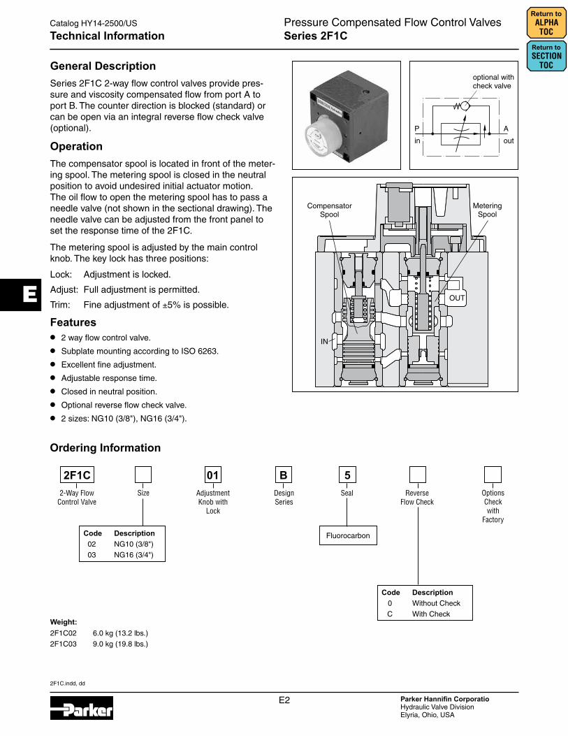
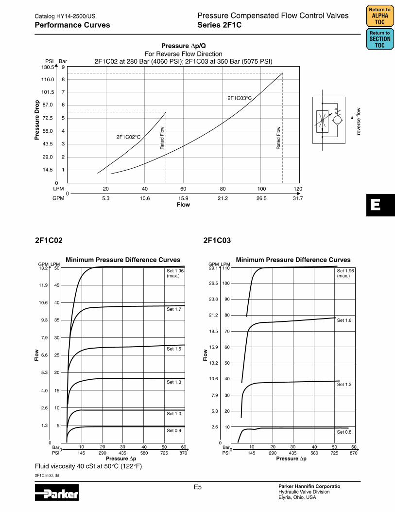
Return to ALPHA TOCPerformance Curves
2F1C02 2F1C03
Fluid viscosity 40 cSt at 50°C (122°F)
2F1C.indd, dd
E5 Parker Hannifin CorporatioHydraulic Valve DivisionElyria, Ohio, USA
Pressure Compensated Flow Control ValvesCatalog HY14-2500/US
Series 2F1C
E
Return to ALPHA TOC
Return to SECTION
TOC
2F1C02 2F1C03
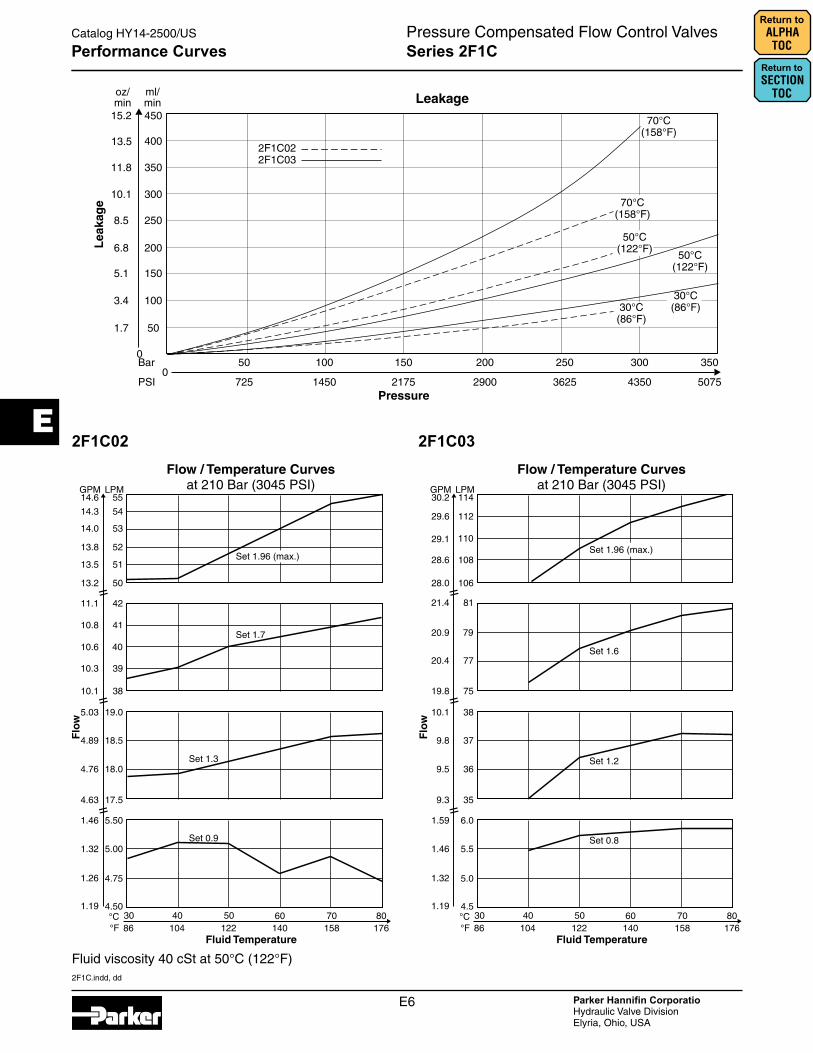
Performance Curves
Fluid viscosity 40 cSt at 50°C (122°F)
2F1C.indd, dd
E6 Parker Hannifin CorporatioHydraulic Valve DivisionElyria, Ohio, USA
Pressure Compensated Flow Control ValvesCatalog HY14-2500/US
Series 2F1C
E
Return to SECTION
TOC
Return to ALPHA TOC
2F1C02 2F1C03
Performance Curves
Fluid viscosity 40 cSt at 50°C (122°F)
2F1C.indd, dd
E7 Parker Hannifin CorporatioHydraulic Valve DivisionElyria, Ohio, USA
Pressure Compensated Flow Control ValvesCatalog HY14-2500/US
Series 2F1C
E
Return to ALPHA TOC
Return to SECTION
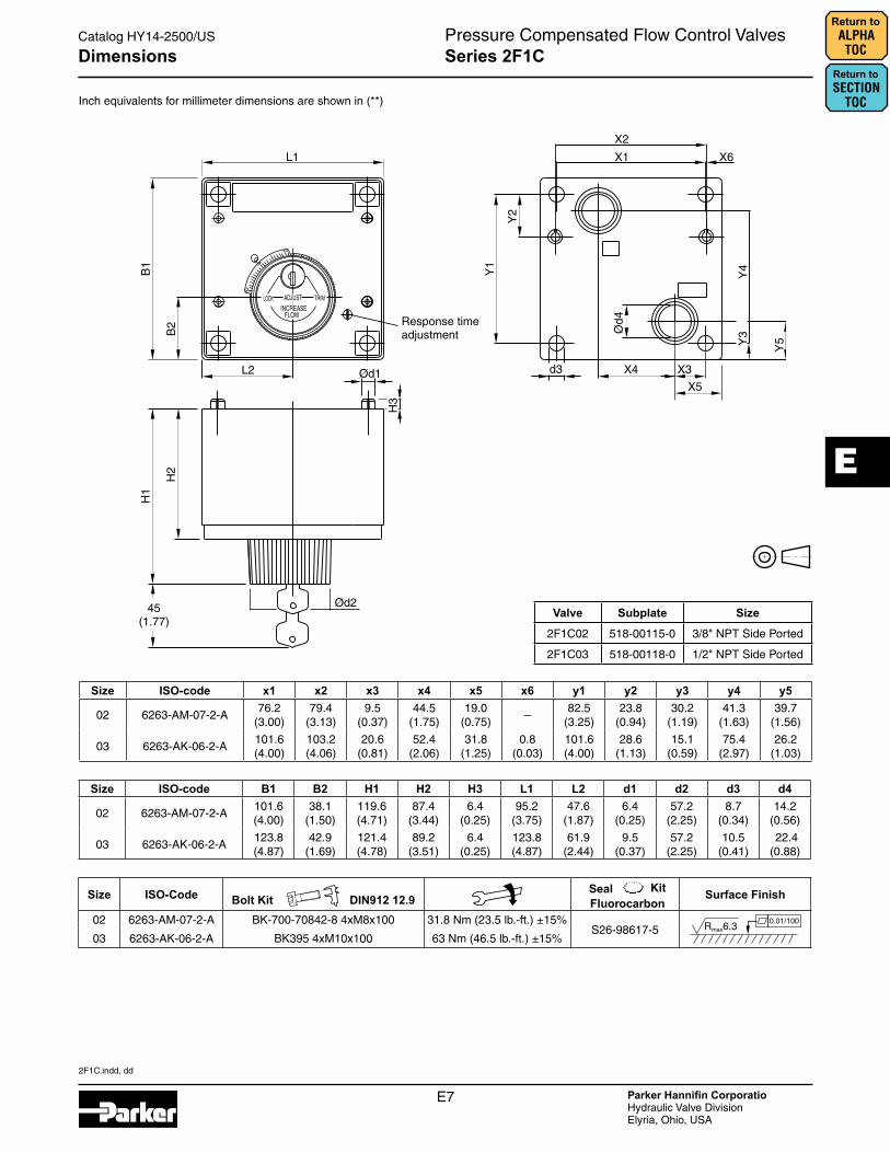
TOCInch equivalents for millimeter dimensions are shown in (**)
Size ISO-code x1 x2 x3 x4 x5 x6 y1 y2 y3 y4 y5
02 6263-AM-07-2-A76.2
(3.00)79.4
(3.13)9.5
(0.37)44.5
(1.75)19.0
(0.75)–
82.5 (3.25)
23.8 (0.94)
30.2 (1.19)
41.3 (1.63)
39.7 (1.56)
03 6263-AK-06-2-A101.6 (4.00)
103.2 (4.06)
20.6 (0.81)
52.4 (2.06)
31.8 (1.25)
0.8 (0.03)
101.6 (4.00)
28.6 (1.13)
15.1 (0.59)
75.4 (2.97)
26.2 (1.03)
Size ISO-code B1 B2 H1 H2 H3 L1 L2 d1 d2 d3 d4
02 6263-AM-07-2-A101.6 (4.00)
38.1 (1.50)
119.6 (4.71)
87.4 (3.44)
6.4 (0.25)
95.2 (3.75)
47.6 (1.87)
6.4 (0.25)
57.2 (2.25)
8.7 (0.34)
14.2 (0.56)
03 6263-AK-06-2-A123.8 (4.87)
42.9 (1.69)
121.4 (4.78)
89.2 (3.51)
6.4 (0.25)
123.8 (4.87)
61.9 (2.44)
9.5 (0.37)
57.2 (2.25)
10.5 (0.41)
22.4 (0.88)
Size ISO-Code Bolt Kit DIN912 12.9 Surface Finish
02 6263-AM-07-2-A BK-700-70842-8 4xM8x100 31.8 Nm (23.5 lb.-ft.) ±15%S26-98617-5
03 6263-AK-06-2-A BK395 4xM10x100 63 Nm (46.5 lb.-ft.) ±15%
Dimensions
FluorocarbonSeal
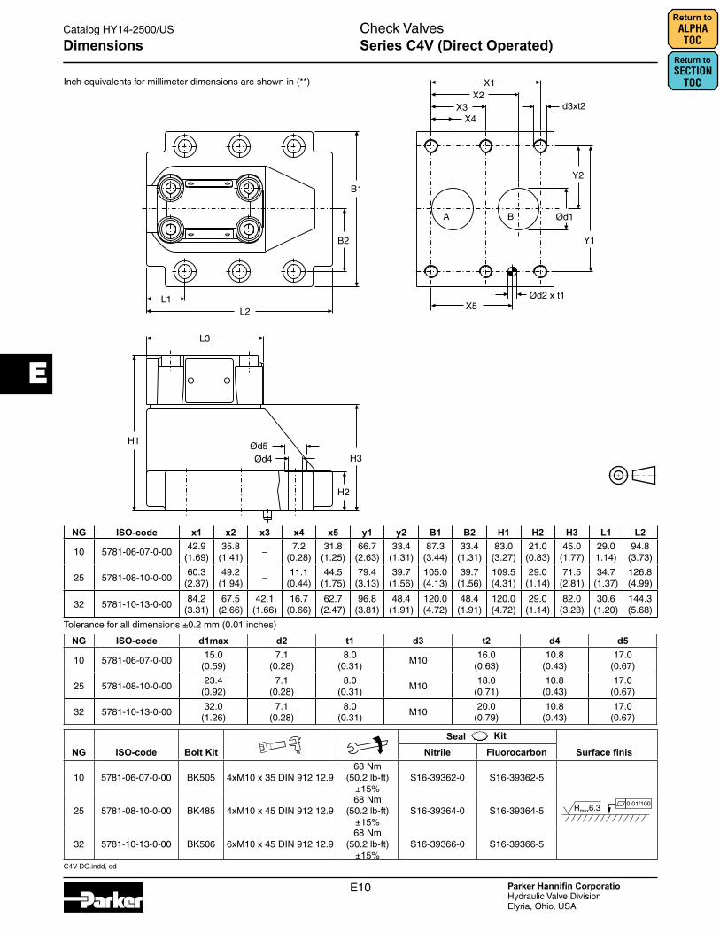
Valve Subplate Size2F1C02 518-00115-0 3/8" NPT Side Ported
2F1C03 518-00118-0 1/2" NPT Side Ported

C4V-DO.indd, dd
E8 Parker Hannifin CorporatioHydraulic Valve DivisionElyria, Ohio, USA
Check ValvesCatalog HY14-2500/US
Series C4V (Direct Operated)
E
Return to SECTION
TOC
Return to ALPHA TOC
General DescriptionSeries C4V direct operated check valves valves allow free flow from A to B. The counter direction is blocked. Series C4V valves are equipped with a leak-free seat type cartridge.
OperationThe pressure arising in port A lifts the poppet from the valve seat and releases the flow to B. In the counter direction, the spring and the pressure on top of the cartridge hold the poppet onto the seat and block the flow.
Features
• High flow, low pressure drop design.
• Minimal internal leakage.
• Six crack pressure options.
C4V10
C4V06
Technical Information
Direct Operated Check Valve
Design Series
BC4V
Ordering Information
Size
Code Description 03 NG10
06 NG25
10 NG32
Maximum Pressure 350 Bar
(5075 PSI)
5
Code Description C4V03 C4V06 / C4V10 1 2.8 Bar (40.6 PSI) 3.5 Bar (50.8 PSI)
2 0.5 Bar (7.3 PSI) 0.5 Bar (7.3 PSI)
3 0.3 Bar (4.4 PSI) 0.3 Bar (4.4 PSI)
4 2.2 Bar (31.9 PSI) 2.2 Bar (31.9 PSI)
5 — 9.0 Bar (130.5 PSI)
6 1.2 Bar (17.4 PSI) 1.2 Bar (17.4 PSI)
7 3.0 Bar (43.5 PSI) —
Seal
Code Description 1 Nitrile
5 Fluorocarbon
Weight:C4V03 2.8 kg (6.2 lbs)
C4V06 4.6 kg (10.1 lbs.)
C4V10 6.1 kg (13.5 lbs.)
Subplate Mounting
3Approximate
Cracking Pressure
0Options Check with
Factory

C4V-DO.indd, dd
E9 Parker Hannifin CorporatioHydraulic Valve DivisionElyria, Ohio, USA
Check ValvesCatalog HY14-2500/US
Series C4V (Direct Operated)
E
Return to ALPHA TOC
Return to SECTION
TOCSpecificationGeneralSize NG10 NG25 NG32Subplate Mounting ISO 5781
Mounting Position Unrestricted
Ambient Temperature Range -20°C to +80°C (-4°F to +176°F)
HydraulicMaximum Operating Pressure 350 Bar (5075 PSI)
Pressure Range 105 Bar (1523 PSI), 210 Bar (3045 PSI), 350 Bar (5075 PSI)
Nominal Flow 150 LPM (39.7 GPM)
270 LPM (71.4 GPM)
450 LPM (119.0 GPM)
Fluid Hydraulic oil to DIN 51524
Viscosity Recommended Permitted
30 to 50 cSt / mm2/s (139 to 232 SSU) 20 to 380 cSt / mm2/s (93 to 1761 SSU)
Fluid Temperature Recommended Permitted
+30°C to +50°C (86°F to +122°F) -20°C to +70°C (-4°F to +158°F)
Filtration ISO Class 4406 (1999) 18/16/13 (meet NAS 1638:7)
Technical Information
Performance Curve
C4V-DO.indd, dd
E10 Parker Hannifin CorporatioHydraulic Valve DivisionElyria, Ohio, USA
Check ValvesCatalog HY14-2500/US
E
Return to SECTION
TOC
Return to ALPHA TOC
Inch equivalents for millimeter dimensions are shown in (**)
Dimensions Series C4V (Direct Operated)
Tolerance for all dimensions ±0.2 mm (0.01 inches)
NG ISO-code x1 x2 x3 x4 x5 y1 y2 B1 B2 H1 H2 H3 L1 L2
10 5781-06-07-0-0042.9
(1.69)35.8
(1.41)–
7.2(0.28)
31.8(1.25)
66.7(2.63)
33.4(1.31)
87.3(3.44)
33.4(1.31)
83.0(3.27)
21.0(0.83)
45.0(1.77)
29.01.14)
94.8(3.73)
25 5781-08-10-0-0060.3
(2.37)49.2
(1.94)–
11.1(0.44)
44.5(1.75)
79.4(3.13)
39.7(1.56)
105.0(4.13)
39.7(1.56)
109.5(4.31)
29.0(1.14)
71.5(2.81)
34.7(1.37)
126.8(4.99)
32 5781-10-13-0-0084.2
(3.31)67.5
(2.66)42.1
(1.66)16.7
(0.66)62.7
(2.47)96.8
(3.81)48.4
(1.91)120.0(4.72)
48.4(1.91)
120.0(4.72)
29.0(1.14)
82.0(3.23)
30.6(1.20)
144.3(5.68)
NG ISO-code d1max d2 t1 d3 t2 d4 d5
10 5781-06-07-0-0015.0
(0.59)7.1
(0.28)8.0
(0.31)M10
16.0(0.63)
10.8(0.43)
17.0(0.67)
25 5781-08-10-0-0023.4
(0.92)7.1
(0.28)8.0
(0.31)M10
18.0(0.71)
10.8(0.43)
17.0(0.67)
32 5781-10-13-0-0032.0
(1.26)7.1
(0.28)8.0
(0.31)M10
20.0(0.79)
10.8(0.43)
17.0(0.67)
NG ISO-code Bolt Kit Nitrile Fluorocarbon Surface finis
10 5781-06-07-0-00 BK505 4xM10 x 35 DIN 912 12.968 Nm
(50.2 lb-ft) ±15%
S16-39362-0 S16-39362-5
25 5781-08-10-0-00 BK485 4xM10 x 45 DIN 912 12.968 Nm
(50.2 lb-ft) ±15%
S16-39364-0 S16-39364-5
32 5781-10-13-0-00 BK506 6xM10 x 45 DIN 912 12.968 Nm
(50.2 lb-ft) ±15%
S16-39366-0 S16-39366-5
Seal

C4V-DO.indd, dd
E11 Parker Hannifin CorporatioHydraulic Valve DivisionElyria, Ohio, USA
Catalog HY14-2500/US
Notes
E
Return to ALPHA TOC
Return to SECTION
TOC
C4V-PO.indd, dd
E12 Parker Hannifin CorporatioHydraulic Valve DivisionElyria, Ohio, USA
Check ValvesCatalog HY14-2500/US
Series C4V (Pilot Operated)
E
Return to SECTION
TOC
Return to ALPHA TOC
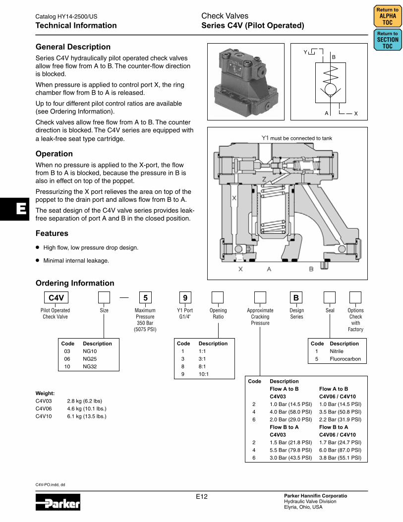
General DescriptionSeries C4V hydraulically pilot operated check valves allow free flow from A to B. The counter-flow direction is blocked.
When pressure is applied to control port X, the ring chamber flow from B to A is released.
Up to four different pilot control ratios are available (see Ordering Information).
Check valves allow free flow from A to B. The counter direction is blocked. The C4V series are equipped with a leak-free seat type cartridge.
OperationWhen no pressure is applied to the X-port, the flow from B to A is blocked, because the pressure in B is also in effect on top of the poppet.
Pressurizing the X port relieves the area on top of the poppet to the drain port and allows flow from B to A.
The seat design of the C4V valve series provides leak-free separation of port A and B in the closed position.
Features
• High flow, low pressure drop design.
• Minimal internal leakage.
must be connected to tank
Technical Information
Ordering Information
Code Description 1 1:1
3 3:1
8 8:1
9 10:1
Pilot Operated Check Valve
Design Series
BC4VSize
Code Description 03 NG10
06 NG25
10 NG32
Maximum Pressure 350 Bar
(5075 PSI)
5
Code Description Flow A to B Flow A to B C4V03 C4V06 / C4V10 2 1.0 Bar (14.5 PSI) 1.0 Bar (14.5 PSI)
4 4.0 Bar (58.0 PSI) 3.5 Bar (50.8 PSI)
6 2.0 Bar (29.0 PSI) 2.2 Bar (31.9 PSI)
Flow B to A Flow B to A C4V03 C4V06 / C4V10 2 1.5 Bar (21.8 PSI) 1.7 Bar (24.7 PSI)
4 5.5 Bar (79.8 PSI) 6.0 Bar (87.0 PSI)
6 3.0 Bar (43.5 PSI) 3.8 Bar (55.1 PSI)
Seal
Code Description 1 Nitrile
5 Fluorocarbon
Weight:C4V03 2.8 kg (6.2 lbs)
C4V06 4.6 kg (10.1 lbs.)
C4V10 6.1 kg (13.5 lbs.)
Y1 Port G1/4"
9Approximate
Cracking Pressure
Opening Ratio
Options Check with
Factory
C4V-PO.indd, dd
E13 Parker Hannifin CorporatioHydraulic Valve DivisionElyria, Ohio, USA
Check ValvesCatalog HY14-2500/US
Series C4V (Pilot Operated)
E
Return to ALPHA TOC
Return to SECTION
TOC
Technical Information
Performance Curve
SpecificationGeneralSize NG10 NG25 NG32Subplate Mounting ISO 5781
Mounting Position Unrestricted
Ambient Temperature Range -20°C to +80°C (-4°F to +176°F)
HydraulicMaximum Operating Pressure 350 Bar (5075 PSI)
Nominal Flow 150 LPM (39.7 GPM) 270 LPM (71.4 GPM) 450 LPM (119.0 GPM)
Fluid Hydraulic oil to DIN 51524
Viscosity Recommended Permitted
30 to 50 cSt / mm2/s (139 to 232 SSU) 20 to 380 cSt / mm2/s (93 to 1761 SSU)
Fluid Temperature Recommended Permitted
+30C° to +50°C (86°F to +122°F) -20°C to +70°C (-4°F to +158°F)
Filtration ISO Class 4406 (1999) 18/16/13 (meet NAS 1638:7)

C4V-PO.indd, dd
E14 Parker Hannifin CorporatioHydraulic Valve DivisionElyria, Ohio, USA
Check ValvesCatalog HY14-2500/US
Series C4V (Pilot Operated)
E
Return to SECTION
TOC
Return to ALPHA TOC
Inch equivalents for millimeter dimensions are shown in (**)
Dimensions
Tolerance for all dimensions ±0.2 mm (0.01 inches)
NG ISO-code B1 B2 H1 H2 H3 H4 H5 H6 L1 L2 L3 L4 L5 L6
10 5781-06-07-0-0087.3
(3.44)33.4
(1.31)83.0
(3.27)21.0
(0.83)62.5
(2.46)– – –
29.4(1.16)
95.2(3.75)
43.7(1.72)
111.0(4.37)
5.0(0.20)
–
25 5781-08-10-0-00105
(4.13)39.7
(1.56)109.5(4.31)
29.0(1.14)
89.0(3.50)
– – –35.1
(1.38)127.2(5.01)
43.7(1.72)
111.0(4.37)
5.0(0.20)
–
32 5781-10-13-0-00120
(4.72)48.4
(1.91)120.0(4.72)
29.0(1.14)
99.5(3.92)
– – –31.0
(1.22)144.7(5.70)
43.7(1.72)
111.0(4.37)
5.0(0.20)
–
NG ISO-code d1max d2max d3 t3 d4 t4 d5 d6
10 5781-06-07-0-0015.0
(0.59)7.0
(0.28)7.1
(0.28)8.0
(0.31)M10
16.0(0.63)
10.8(0.43)
17.0(0.67)
25 5781-08-10-0-0023.4
(0.92)7.1
(0.28)7.1
(0.28)8.0
(0.31)M10
18.0(0.71)
10.8(0.43)
17.0(0.67)
32 5781-10-13-0-0032.0
(1.26)7.1
(0.28)7.1
(0.28)8.0
(0.31)M10
20.0(0.79)
10.8(0.43)
17.0(0.67)
NG ISO-code x1 x2 x3 x4 x5 x6 x7 y1 y2 y3 y4 y5 y6
10 5781-06-07-0-0042.9
(1.69)35.8
(1.41)– –
7.2(0.28)
21.5(0.85)
31.8(1.25)
66.7(2.63)
58.8(2.31)
33.4(1.31)
– – –
25 5781-08-10-0-0060.3
(2.37)49.2
(1.94)– –
11.1(0.44)
20.6(0.81)
44.5(1.75)
79.4(3.13)
73.0(2.87)
39.7(1.56)
– – –
32 5781-10-13-0-0084.2
(3.31)67.5
(2.66)–
42.1(1.66)
16.7(0.66)
24.6(0.97)
62.7(2.47)
96.8(3.81)
92.8(3.65)
48.4(1.91)
– – –
NG ISO-code Bolt Kit Nitrile Fluorocarbon Surface finis
10 5781-06-07-0-00 BK505 4xM10 x 35 DIN 912 12.968 Nm
(50.2 lb-ft) ±15%
S16-39362-0 S16-39362-5
25 5781-08-10-0-00 BK485 4xM10 x 45 DIN 912 12.968 Nm
(50.2 lb-ft) ±15%
S16-39364-0 S16-39364-5
32 5781-10-13-0-00 BK506 6xM10 x 45 DIN 912 12.968 Nm
(50.2 lb-ft) ±15%
S16-39366-0 SS16-39366-5
Seal
NG ISO-code Subplate Size 10 5781-06-07-0-00 SPP3M6B910 A, B = 3/4" BSPP x, y = 1/4" BSPP
25 5781-08-10-0-00 SPP6M8B910 A, B = 1" BSPP x, y = 1/4" BSPP
32 5781-10-13-0-00 SPP10M12B910 A, B = 1 1/2" BSPP x, y = 1/4" BSPP

C5P.indd, dd
E15 Parker Hannifin CorporatioHydraulic Valve DivisionElyria, Ohio, USA
Check ValvesCatalog HY14-2500/US
Series C5P (Pilot Operated)
E
Return to ALPHA TOC
Return to SECTION
TOCGeneral DescriptionSeries C5P pilot operated check valves have a similar design to the subplate mounted C5V series. The SAE flanges allow to mount directly on the flanges of actua-tors to achieve a very compact design.
OperationWhen no pressure is applied to the X-port, the flow from B to A is blocked, because the pressure in B is also in effect on top of the poppet.
Pressurizing the X port relieves the area on top of the poppet to the drain port and allows flow from B to A.
The seat design of the C5P valve series provides leak-free separation of port A and B in the closed position.
Features• Pilot operated check valve.
• 2-port body with SAE 61 flange.
• 3 sizes (SAE 3/4", 1", 1 1/4").
• 4 opening ratios.
• Valves with position control are available on request.
Technical Information
Weight:C5P06 3.9 kg (8.6 lbs.)
C5P08 4.4 kg (9.7 lbs.)
C5P10 5.7 kg (12.6 lbs.)
Pilot Operated Check Valve
Size SAE 61 Interface
Pilot Ports
Options Check with
Factory
C5P
Code Description 06 SAE 3/4"
08 SAE 1"
10 SAE 1 1/4"
Code Description 4 280 Bar (4060 PSI) Size 10 (SAE 61)
5 350 Bar (5075 PSI) Sizes 06/08 (SAE 61)
Opening Ratio
Code Description 1 Nitrile
5 Fluorocarbon
SealDesign Series
A
Code Description 1 Pilot Operated 1:1 Ratio
3 Pilot Operated 3:1 Ratio
8 Pilot Operated 8:1 Ratio
9 Pilot Operated 10:1 Ratio
2Cracking Pressure
Code Size Flow A–B Flow B–A 2 06 1.0 Bar (14.5 PSI) 1.5 Bar (21.8 PSI) 08/10 1.0 Bar (14.5 PSI) 1.7 Bar (24.7 PSI)
4 06 4.0 Bar (58.0 PSI) 5.5 Bar (79.8 PSI) 08/10 3.5 Bar (50.8 PSI) 6.0 Bar (87.0 PSI)
6 06 2.0 Bar (29.0 PSI) 3.0 Bar (43.5 PSI) 08/10 2.2 Bar (31.9 PSI) 3.8 Bar (55. 1 PSI)
X1 and Y1 = SAE 4
Ordering Information

C5P.indd, dd
E16 Parker Hannifin CorporatioHydraulic Valve DivisionElyria, Ohio, USA
Check ValvesCatalog HY14-2500/US
Series C5P (Pilot Operated)
E
Return to SECTION
TOC
Return to ALPHA TOC
SpecificationGeneralSize 06 (3/4") 08 (1") 10 (1 1/4")Mounting 2-port in-line flange SAE 61
Mounting Position Unrestricted
Ambient Temprature -20°C to +50°C (-4°F to +122°F)
HydraulicMaximum Operating Pressure
Ports A, B Port Y1
350 Bar (5075 PSI) 30 Bar (435 PSI)
350 Bar (5075 PSI) 30 Bar (435 PSI)
280 Bar (4060 PSI) 30 Bar (435 PSI)
Nominal Flow 180 LPM (47.6 GPM) 360 LPM (95.2 GPM) 600 LPM (158.7 GPM)
Fluid Hydraulic oil in accordance with DIN 51524...51525
Fluid Temperature -20°C to +80°C (-4°F to +176°F)
Viscosity Permitted Recommended
10 to 650 cSt / mm2/s (46 to 3013 SSU) 30 cSt / mm2/s (139 SSU)
Filtration ISO 4406 (1999) 18/16/13 (acc. NAS 1638:7)
Technical Information
C5P06 C5P08
C5P10
Performance Curves
C5P.indd, dd
E17 Parker Hannifin CorporatioHydraulic Valve DivisionElyria, Ohio, USA
Check ValvesCatalog HY14-2500/US
Series C5P (Pilot Operated)
E
Return to ALPHA TOC
Return to SECTION
TOCInch equivalents for millimeter dimensions are shown in (**)
Dimensions
Ports
Series L1 L2 L3 L4 L5 B1 H1 H2 H3 H4 D1 D2
C5P0622.2
(0.87)95.8
(3.77)119.8 4.72)
137.0 (5.39)
67.3 (2.65)
60.0 (2.36)
37.0 (1.46)
47.6 (1.87)
90.0 (3.54)
128.0 (5.04)
19.0 (0.75)
10.5 (0.41)
C5P0826.2
(1.03)112.9 (4.44)
139.4 (5.49)
137.0 (5.39)
67.3 (2.65)
60.0 (2.36)
45.0 (1.77)
52.4 (2.06)
96.0 (3.78)
134.0 (5.28)
25.0 (0.93)
10.5 (0.41)
C5P1030.2
(1.19)112.9 (4.44)
146.9 (5.78)
137.0 (5.39)
67.3 (2.65)
75.0 (2.95)
48.0 (1.39)
58.7 (2.31)
109.0 (4.29)
147.0 (5.79)
32.0 (1.26)
12.5 (0.49)
Port Function Port SizeC5P06 C5P08 C5P10
A Inlet or Outlet 3/4" SAE 61 1" SAE 61 1 1/4" SAE 61B Outlet or Inlet 3/4" SAE 61 1" SAE 61 1 1/4" SAE 61
X1 External Pilot Port SAE 4Y1 External Pilot Drain SAE 4
Dimensions
Seal KitsNG Nitrile Fluorocarbon06 S26-59404-0 S26-59404-5
08 S26-59405-0 S26-59405-5
10 S26-59406-0 S26-59406-5
C5V.indd, dd
E18 Parker Hannifin CorporatioHydraulic Valve DivisionElyria, Ohio, USA
Check ValvesCatalog HY14-2500/US
E
Series C5V (Direct Operated)Return to SECTION
TOC
Return to ALPHA TOC
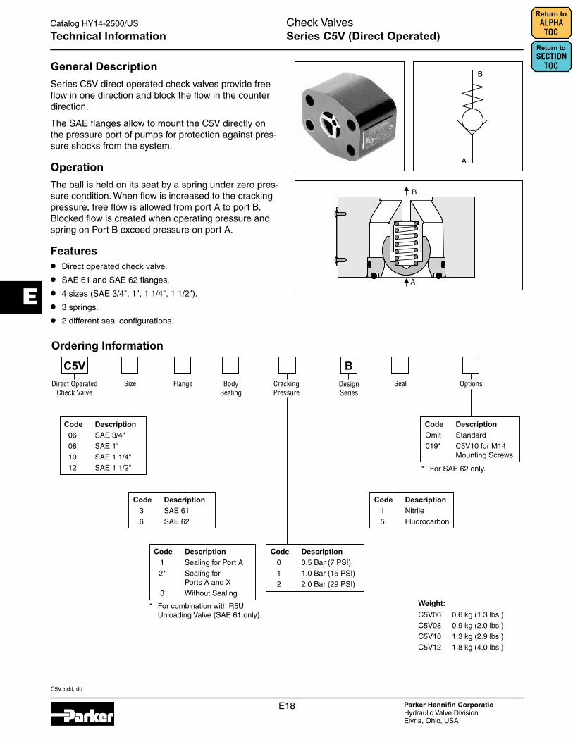
General DescriptionSeries C5V direct operated check valves provide free flow in one direction and block the flow in the counter direction.
The SAE flanges allow to mount the C5V directly on the pressure port of pumps for protection against pres-sure shocks from the system.
OperationThe ball is held on its seat by a spring under zero pres-sure condition. When flow is increased to the cracking pressure, free flow is allowed from port A to port B. Blocked flow is created when operating pressure and spring on Port B exceed pressure on port A.
Features• Direct operated check valve.
• SAE 61 and SAE 62 flanges.
• 4 sizes (SAE 3/4", 1", 1 1/4", 1 1/2").
• 3 springs.
• 2 different seal configurations.
Technical Information
Code Description 1 Nitrile
5 Fluorocarbon
Code Description Omit Standard
019* C5V10 for M14 Mounting Screws
Direct Operated Check Valve
Size Flange Body Sealing
Seal Options
C5VDesign Series
Code Description 06 SAE 3/4"
08 SAE 1"
10 SAE 1 1/4"
12 SAE 1 1/2"
Code Description 3 SAE 61
6 SAE 62
Cracking Pressure
B
Code Description 0 0.5 Bar (7 PSI)
1 1.0 Bar (15 PSI)
2 2.0 Bar (29 PSI)
Code Description 1 Sealing for Port A
2* Sealing for Ports A and X
3 Without Sealing
* For combination with R5U Unloading Valve (SAE 61 only).
* For SAE 62 only.
Weight:C5V06 0.6 kg (1.3 lbs.)
C5V08 0.9 kg (2.0 lbs.)
C5V10 1.3 kg (2.9 lbs.)
C5V12 1.8 kg (4.0 lbs.)
Ordering Information
C5V.indd, dd
E19 Parker Hannifin CorporatioHydraulic Valve DivisionElyria, Ohio, USA
Check ValvesCatalog HY14-2500/US
E
Series C5V (Direct Operated)
Return to ALPHA TOC
Return to SECTION
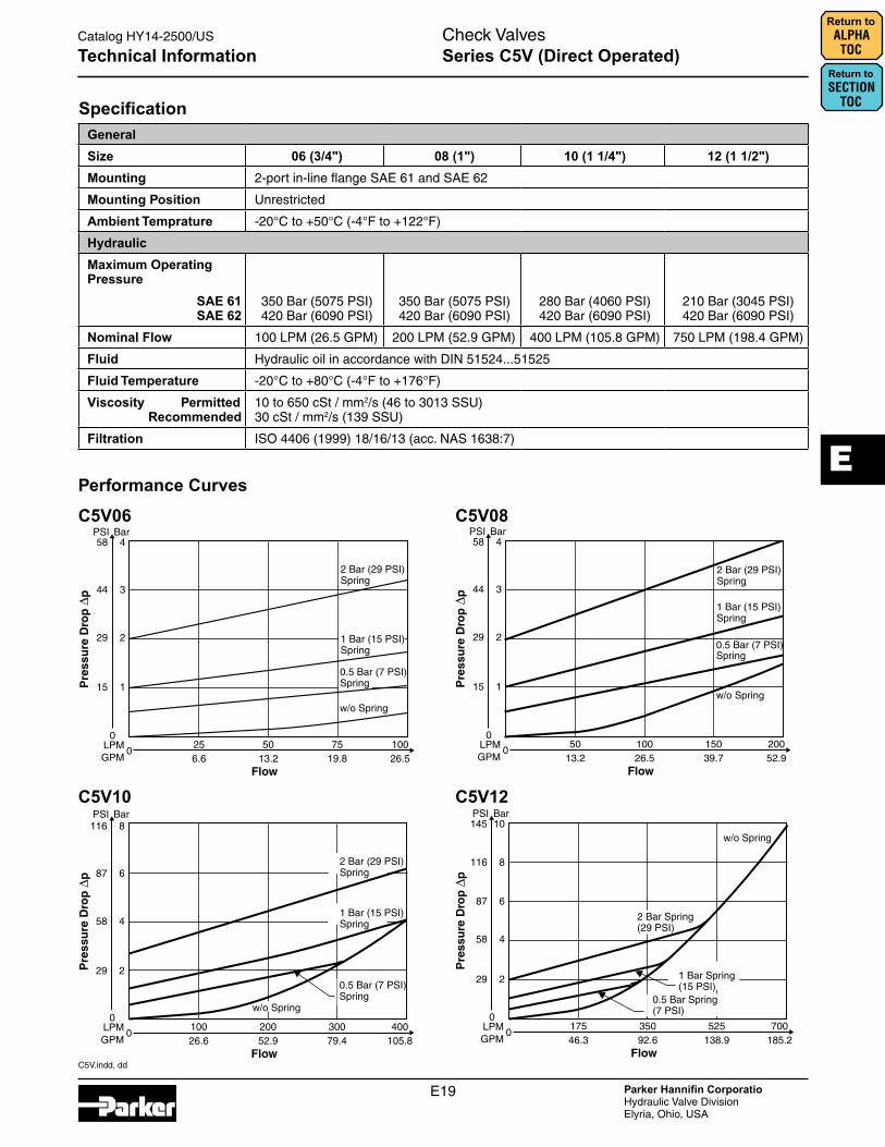
TOCSpecificationGeneralSize 06 (3/4") 08 (1") 10 (1 1/4") 12 (1 1/2")Mounting 2-port in-line flange SAE 61 and SAE 62
Mounting Position Unrestricted
Ambient Temprature -20°C to +50°C (-4°F to +122°F)
HydraulicMaximum Operating Pressure
SAE 61 SAE 62
350 Bar (5075 PSI) 420 Bar (6090 PSI)
350 Bar (5075 PSI) 420 Bar (6090 PSI)
280 Bar (4060 PSI) 420 Bar (6090 PSI)
210 Bar (3045 PSI) 420 Bar (6090 PSI)
Nominal Flow 100 LPM (26.5 GPM) 200 LPM (52.9 GPM) 400 LPM (105.8 GPM) 750 LPM (198.4 GPM)
Fluid Hydraulic oil in accordance with DIN 51524...51525
Fluid Temperature -20°C to +80°C (-4°F to +176°F)
Viscosity Permitted Recommended
10 to 650 cSt / mm2/s (46 to 3013 SSU) 30 cSt / mm2/s (139 SSU)
Filtration ISO 4406 (1999) 18/16/13 (acc. NAS 1638:7)
Technical Information
C5V06
C5V10 C5V12
C5V08Performance Curves

C5V.indd, dd
E20 Parker Hannifin CorporatioHydraulic Valve DivisionElyria, Ohio, USA
Check ValvesCatalog HY14-2500/US
E
Series C5V (Direct Operated)Return to SECTION
TOC
Return to ALPHA TOC
Inch equivalents for millimeter dimensions are shown in (**)
Series Nominal Size L1 L2 L3 H1 H2 H3 B1 D1 D2 D3 + 0.8 D4
C5V06 3/4"
SAE 6148.0
(1.89)22.2
(0.87)27.2
(1.07)64.0
(2.52)47.6
(1.87)22.4
(0.88)45.0
(1.77)10.5
(0.41)Ø3.0 (0.12)
19.0 (0.75)
19.0 (0.75)
SAE 6248.0
(1.89)23.8
(0.94)27.2
(1.07)64.0
(2.52)50.8
(2.00)22.4
(0.88)45.0
(1.77)10.5
(0.41)–
19.0 (0.75)
19.0 (0.75)
C5V08 1"SAE 61
60.0 (2.36)
26.2 (1.03)
27.2 (1.07)
74.0 (2.91)
52.4 (2.06)
22.4 (0.88)
45.0 (1.77)
10.5 (0.41)
Ø3.0 (0.12)
25.0 (0.98)
25.0 (0.98)
SAE 6260.0
(2.36)27.8
(1.09)27.2
(1.07)74.0
(2.91)57.2
(2.25)22.4
(0.88)45.0
(1.77)12.5
(0.49)–
25.0 (0.98)
25.0 (0.98)
C5V10 1 1/4"SAE 61
68.0 (2.68)
30.2 (1.19)
27.2 (1.07)
85.0 (3.35)
58.7 (2.31)
22.4 (0.88)
50.0 (1.97)
12.5 (0.49)
Ø3.0 (0.12)
32.0 (1.26)
32.0 (1.26)
SAE 6268.0
(2.68)31.8
(1.25)27.2
(1.07)85.0
(3.35)66.7
(2.63)22.4
(0.88)50.0
(1.97)13.5* (0.53)
–32.0
(1.26)32.0
(1.26)
C5V12 1 1/2"SAE 61
80.0(3.15)
35.7 (1.41)
27.2 (1.07)
104.0 (4.09)
69.8 (2.75)
22.4 (0.88)
50.0 (1.97)
13.5 (0.53)
Ø3.0 (0.12)
42.0 (1.65)
38.0 (1.50)
SAE 6280.0
(3.15)36.5
(1.44)27.2
(1.07)104.0 (4.09)
79.4 (3.13)
22.4 (0.88)
50.0 (1.97)
17.0 (0.67)
–42.0
(1.65)38.0
(1.50)
* D1 = 15 (0.59) at option code 019 for M14 mounting screws.
Dimensions
Seal KitsNG Nitrile Fluorocarbon3 S26-75409-0 S26-75409-5
6 S26-75410-0 S26-75410-5
10 S26-75411-0 S26-75411-5
12 S26-75412-0 S26-75412-5
offerofsale.indd, dd
E21 Parker Hannifin CorporatioHydraulic Valve DivisionElyria, Ohio, USA
Catalog HY14-2500/US
Terms of Sale with Warranty Limitations
E
11. Buyer’s Obligation; Rights of Seller. To secure payment of all sums due or oth-erwise, Seller shall retain a security interest in the goods delivered and this agreement shall be deemed a Security Agreement under the Uniform Commercial Code. Buyer authorizes Seller as its attorney to execute and file on Buyer’s behalf all documents Seller deems necessary to perfect its security interest. Seller shall have a security interest in, and lien upon, any property of Buyer in Seller’s possession as security for the payment of any amounts owed to Seller by Buyer.12. Improper Use and Indemnity. Buyer shall indemnify, defend, and hold Seller harmless from any claim, liability, damages, lawsuits, and costs (including attorney fees), whether for personal injury, property damage, patent, trademark or copyright infringement or any other claim, brought by or incurred by Buyer, Buyer’s employees, or any other person, arising out of: (a) improper selection, improper application or other misuse of Products purchased by Buyer from Seller; (b) any act or omission, negligent or otherwise, of Buyer; (c) Seller’s use of patterns, plans, drawings, or specifications furnished by Buyer to manufacture Product; or (d) Buyer’s failure to comply with these terms and conditions. Seller shall not indemnify Buyer under any circumstance except as otherwise provided.13. Cancellations and Changes. Orders shall not be subject to cancellation or change by Buyer for any reason, except with Seller’s written consent and upon terms that will indemnify, defend and hold Seller harmless against all direct, incidental and consequential loss or damage. Seller may change product features, specifications, designs and availability with notice to Buyer.14. Limitation on Assignment. Buyer may not assign its rights or obligations under this agreement without the prior written consent of Seller.15. Entire Agreement. This agreement contains the entire agreement between the Buyer and Seller and constitutes the final, complete and exclusive expression of the terms of the agreement. All prior or contemporaneous written or oral agreements or negotiations with respect to the subject matter are herein merged. 16. Waiver and Severability. Failure to enforce any provision of this agreement will not waive that provision nor will any such failure prejudice Seller’s right to enforce that provision in the future. Invalidation of any provision of this agreement by legislation or other rule of law shall not invalidate any other provision herein. The remaining provisions of this agreement will remain in full force and effect.17. Termination. This agreement may be terminated by Seller for any reason and at any time by giving Buyer thirty (30) days written notice of termination. In addition, Seller may by written notice immediately terminate this agreement for the following: (a) Buyer commits a breach of any provision of this agreement (b) the appointment of a trustee, receiver or custodian for all or any part of Buyer’s property (c) the filing of a petition for relief in bankruptcy of the other Party on its own behalf, or by a third party (d) an assign-ment for the benefit of creditors, or (e) the dissolution or liquidation of the Buyer.18. Governing Law. This agreement and the sale and delivery of all Products here-under shall be deemed to have taken place in and shall be governed and construed in accordance with the laws of the State of Ohio, as applicable to contracts executed and wholly performed therein and without regard to conflicts of laws principles. Buyer irrevocably agrees and consents to the exclusive jurisdiction and venue of the courts of Cuyahoga County, Ohio with respect to any dispute, controversy or claim arising out of or relating to this agreement. Disputes between the parties shall not be settled by arbitration unless, after a dispute has arisen, both parties expressly agree in writing to arbitrate the dispute. 19. Indemnity for Infringement of Intellectual Property Rights. Seller shall have no liability for infringement of any patents, trademarks, copyrights, trade dress, trade secrets or similar rights except as provided in this Section. Seller will defend and indemnify Buyer against allegations of infringement of U.S. patents, U.S. trademarks, copyrights, trade dress and trade secrets (“Intellectual Property Rights”). Seller will defend at its expense and will pay the cost of any settlement or damages awarded in an action brought against Buyer based on an allegation that a Product sold pursuant to this Agreement infringes the Intellectual Property Rights of a third party. Seller’s obligation to defend and indemnify Buyer is contingent on Buyer notifying Seller within ten (10) days after Buyer becomes aware of such allegations of infringement, and Seller having sole control over the defense of any allegations or actions including all negotiations for settlement or compromise. If a Product is subject to a claim that it infringes the Intellectual Property Rights of a third party, Seller may, at its sole expense and option, procure for Buyer the right to continue using the Product, replace or modify the Product so as to make it noninfringing, or offer to accept return of the Product and return the purchase price less a reasonable allowance for depreciation. Notwithstanding the foregoing, Seller shall have no liability for claims of infringement based on information provided by Buyer, or directed to Products delivered hereunder for which the designs are specified in whole or part by Buyer, or infringements resulting from the modification, combination or use in a system of any Product sold hereunder. The foregoing provisions of this Section shall constitute Seller’s sole and exclusive liability and Buyer’s sole and exclusive remedy for infringement of Intellectual Property Rights.20. Taxes. Unless otherwise indicated, all prices and charges are exclusive of excise, sales, use, property, occupational or like taxes which may be imposed by any taxing authority upon the manufacture, sale or delivery of Products.21. Equal Opportunity Clause. For the performance of government contracts and where dollar value of the Products exceed $10,000, the equal employment opportunity clauses in Executive Order 11246, VEVRAA, and 41 C.F.R. §§ 60-1.4(a), 60-741.5(a), and 60-250.4, are hereby incorporated. 6/09
1. Terms and Conditions. Seller’s willingness to offer Products, or accept an order for Products, to or from Buyer is expressly conditioned on Buyer’s assent to these Terms and Conditions and to the terms and conditions found on-line at www.parker.com/saleterms/. Seller objects to any contrary or additional term or condition of Buyer’s order or any other document issued by Buyer.2. Price Adjustments; Payments. Prices stated on the reverse side or preceding pages of this document are valid for 30 days. After 30 days, Seller may change prices to reflect any increase in its costs resulting from state, federal or local legislation, price increases from its suppliers, or any change in the rate, charge, or classification of any carrier. The prices stated on the reverse or preceding pages of this document do not include any sales, use, or other taxes unless so stated specifically. Unless otherwise specified by Seller, all prices are F.O.B. Seller’s facility, and payment is due 30 days from the date of invoice. After 30 days, Buyer shall pay interest on any unpaid invoices at the rate of 1.5% per month or the maximum allowable rate under applicable law.3. Delivery Dates; Title and Risk; Shipment. All delivery dates are approximate and Seller shall not be responsible for any damages resulting from any delay. Regardless of the manner of shipment, title to any products and risk of loss or damage shall pass to Buyer upon tender to the carrier at Seller’s facility (i.e., when it’s on the truck, it’s yours). Unless otherwise stated, Seller may exercise its judgment in choosing the carrier and means of delivery. No deferment of shipment at Buyers’ request beyond the respec-tive dates indicated will be made except on terms that will indemnify, defend and hold Seller harmless against all loss and additional expense. Buyer shall be responsible for any additional shipping charges incurred by Seller due to Buyer’s changes in shipping, product specifications or in accordance with Section 13, herein.4. Warranty. Seller warrants that the Products sold hereunder shall be free from defects in material or workmanship for a period of eighteen months from the date of delivery to Buyer. The prices charged for Seller’s products are based upon the exclusive limited warranty stated above, and upon the following disclaimer: DISCLAIMER OF WARRANTY: THIS WARRANTY COMPRISES THE SOLE AND ENTIRE WARRANTY PERTAINING TO PRODUCTS PROVIDED HEREUNDER. SELLER DISCLAIMS ALL OTHER WARRANTIES, EXPRESS AND IMPLIED, INCLUDING MERCHANTABILITY AND FITNESS FOR A PARTICULAR PURPOSE.5. Claims; Commencement of Actions. Buyer shall promptly inspect all Products upon delivery. No claims for shortages will be allowed unless reported to the Seller within 10 days of delivery. No other claims against Seller will be allowed unless asserted in writing within 60 days after delivery or, in the case of an alleged breach of warranty, within 30 days after the date within the warranty period on which the defect is or should have been discovered by Buyer. Any action based upon breach of this agreement or upon any other claim arising out of this sale (other than an action by Seller for any amount due to Seller from Buyer) must be commenced within thirteen months from the date of tender of delivery by Seller or, for a cause of action based upon an alleged breach of warranty, within thirteen months from the date within the warranty period on which the defect is or should have been discovered by Buyer.6. LIMITATION OF LIABILITY. UPON NOTIFICATION, SELLER WILL, AT ITS OPTION, REPAIR OR REPLACE A DEFECTIVE PRODUCT, OR REFUND THE PURCHASE PRICE. IN NO EVENT SHALL SELLER BE LIABLE TO BUYER FOR ANY SPECIAL, INDIRECT, INCIDENTAL OR CONSEQUENTIAL DAMAGES ARISING OUT OF, OR AS THE RESULT OF, THE SALE, DELIVERY, NON-DELIVERY, SERVICING, USE OR LOSS OF USE OF THE PRODUCTS OR ANY PART THEREOF, OR FOR ANY CHARGES OR EXPENSES OF ANY NATURE INCURRED WITHOUT SELLER’S WRITTEN CONSENT, EVEN IF SELLER HAS BEEN NEGLIGENT, WHETHER IN CONTRACT, TORT OR OTHER LEGAL THEORY. IN NO EVENT SHALL SELLER’S LIABILITY UNDER ANY CLAIM MADE BY BUYER EXCEED THE PURCHASE PRICE OF THE PRODUCTS.7. Contingencies. Seller shall not be liable for any default or delay in performance if caused by circumstances beyond the reasonable control of Seller.8. User Responsibility. The user, through its own analysis and testing, is solely responsible for making the final selection of the system and Product and assuring that all performance, endurance, maintenance, safety and warning requirements of the application are met. The user must analyze all aspects of the application and follow applicable industry standards and Product information. If Seller provides Product or system options, the user is responsible for determining that such data and specifica-tions are suitable and sufficient for all applications and reasonably foreseeable uses of the Products or systems.9. Loss to Buyer’s Property. Any designs, tools, patterns, materials, drawings, confi-dential information or equipment furnished by Buyer or any other items which become Buyer’s property, may be considered obsolete and may be destroyed by Seller after two consecutive years have elapsed without Buyer placing an order for the items which are manufactured using such property. Seller shall not be responsible for any loss or damage to such property while it is in Seller’s possession or control.10. Special Tooling. A tooling charge may be imposed for any special tooling, including without limitation, dies, fixtures, molds and patterns, acquired to manufacture Products. Such special tooling shall be and remain Seller’s property notwithstanding payment of any charges by Buyer. In no event will Buyer acquire any interest in apparatus belonging to Seller which is utilized in the manufacture of the Products, even if such apparatus has been specially converted or adapted for such manufacture and notwithstanding any charges paid by Buyer. Unless otherwise agreed, Seller shall have the right to alter, discard or otherwise dispose of any special tooling or other property in its sole discretion at any time.
Offer of SaleThe items described in this document and other documents and descriptions provided by Parker Hannifin Corporation, Hydraulics Group, and its authorized distributors (“Seller”) are hereby offered for sale at prices to be established by Seller. This offer and its acceptance by any customer (“Buyer”) shall be governed by all of the following Terms and Conditions. Buyer’s order for any item described in its document, when communicated to Seller verbally, or in writing, shall constitute acceptance of this offer. All goods or work described will be referred to as “Products”.
Return to ALPHA TOC
Return to SECTION
TOC

E
E22
Return to SECTION
TOC
Return to ALPHA TOC
Parker Safety Guide for Selecting and Using Hydraulic Valves and Related AccessoriesWARNING: Failure or improper selection or improper use of Parker Hydraulic Valve Division (HVD) Valves or related accessories (“Products”) can cause death, personal injury and property damage. Possible consequences of failure or improper use of these Products include but are not limited to:
■ Valves or parts thereof thrown off at high speed ■ Contactwithfluidthatmaybehot,cold,toxicorotherwiseinjurious
■ Highvelocityfluiddischarge ■ Injuriesresultingfrominjection,inhalationorexposuretofluids
■ Explosionorburningoftheconveyedfluid ■ Injury from handling a heavy item (dropped, awkward lift)
■ Contact with suddenly moving or falling objects controlled by the Valve ■ Electric shock from improper handling of solenoid connections
■ Injectionsbyhigh-pressurefluiddischarge ■ Injuryfromsliporfallonspilledorleakedfluid
Before selecting or using any of these Products, it is important that you read and follow the instructions below. In general, the Products are not approved forin-flightaerospaceapplications.ConsultthefactoryforthefewthatareFAAapproved.
1.0 GENERAL INSTRUCTIONS1.1 Scope: This safety guide provides instructions for selecting and using (including assembling, installing and maintaining) these Products. For convenience all items
inthisguidearecalled“Valves”.ThissafetyguideisasupplementtoandistobeusedinconjunctionwiththespecificParkercatalogsforthespecificValvesand/oraccessories being considered for use. See item 1.6 below for obtaining those catalogs.
1.2 Fail-Safe: Valves can and do fail without warning for many reasons. Design all systems and equipment in a fail-safe mode, so that failure of the Valve or Valve Assembly will not endanger persons or property.
1.3 Safety Devices: Never disconnect, override, circumvent or otherwise disable any safety lockout on any system whether powered by HVD Valves or any motion control system of any manufacturer. (e.g. Automatic shut-off on a riding lawn mower should the operator get out of the seat).
1.4 Distribution: Provide a copy of this safety guide to each person that is responsible for selecting or using HVD Valve Products. Do not select HVD Valves without thoroughlyreadingandunderstandingthissafetyguideaswellasthespecificParkercatalogsfortheProductsconsideredorselected.
1.5 User Responsibility: Due the wide variety of operating conditions and applications for Valves, HVD and its distributors do not represent or warrant that any particularValveissuitableforanyspecificsystem.Thissafetyguidedoesnotanalyzealltechnicalparametersthatmustbeconsideredinselectingaproduct.Theuser, through its own analysis and testing is solely responsible for:■MakingthefinalselectionoftheValve■Assuringthattheuser’srequirementsaremetandthattheapplicationpresentsnohealthorsafetyhazards.■Providing all appropriate health and safety warnings on the equipment on which the Valves are used.
■Assuring compliance with all applicable government and industry standards.
1.6 Additional Questions: Call the appropriate Parker technical service department if you have any questions or require any additional information. See the Parker publication for the product being considered or used, or call 1-800-CPARKER, or go to www.parker.com , for the telephone numbers of the appropriate technical service department. For additional copies of this or any other Parker Safety Guide go to www.parker.com and click on the safety button on the opening page. Catalogs and/orcatalognumbersforthevariousHVDValveProductscanbeobtainedbycallingHVDat440-366-5100.Phonenumbersandcataloginformationisalsoavailable on the Parker website, www.parker.com .
2.0 VALVE SELECTION INSTRUCTIONS2.1 Pressure: ValveselectionmustbemadesothatthemaximumworkingpressureoftheValveisequaltoorgreaterthanthemaximumsystempressure.Surge,impulse
orpeaktransientpressuresinthesystemmustbebelowthemaximumworkingpressureoftheValve.Surge,impulseandpeakpressurescanusuallybedeterminedby sensitive electrical instrumentation that measures and indicates pressures at millisecond intervals. Mechanical pressure gauges indicate only average pressure and cannot be used to determine surge, impulse or peak transient pressures. Burst pressure ratings if given or known are for manufacturing purposes only and are not an indicationthattheProductcanbeusedinapplicationsattheburstpressureorotherwiseabovethemaximumworkingpressure.
2.2 Temperature: ThefluidtemperaturemustberegulatedorcontrolledsothattheoperatingviscosityofthefluidismaintainedatalevelspecifiedfortheparticularValve product. Such ranges are given in the product catalogs or can be obtained from the appropriate customer service department for the particular Valve product.
2.3 Fluid Compatibility:ThefluidconveyedinValveshasdirectimplicationsontheValveselection.ThefluidmustbechemicallycompatiblewiththeValvecomponentmaterials.Elastomerseals,brass,castiron,aluminumforexampleallarepotentiallyaffectedbycertainfluids.Additionally,fluidselectionaffectstheperformanceofvariousValves.ConsiderationsrelativetofluidselectionareoutlinedinthespecificHVDValveproductcatalog.Ofparticularimportanceisthatthefluidbeforhydraulicuse,containtheproperadditivesandwearinhibitors.See1.6“AdditionalQuestions”aboveforinformationtoobtainsuchHVDcatalogs.
2.4 Changing Fluids: Ifasystemrequiresadifferentfluid,itshouldbedonewiththeguidanceinnumber2.3above.Additionally,itmaybenecessarytoflushthesystem(includingtheValves)toremoveanyofthepreviousfluid.ConsulttheParkerValveDivisionforguidance.
2.5 Size: Transmissionofpowerbymeansofpressurizedfluidvarieswithpressureandrateofflow.Thesizeofthecomponentsmustbeadequatetokeeppressurelossestoaminimumandavoiddamageduetoheatgenerationorexcessivefluidvelocity.
2.6 Placement: InstallationofValvesmusttakeintoaccounttheorientationoftheValveandtheproximityoftheValvetootherpartsofthesystem.Thisincludesbutisnot limited to closeness to hot and cold areas, access for servicing and operation as well as orientation for proper connectors.
2.7 Ports: ConnectionofValvesinsystemscanbebythreadedports,sub-basesurfaces,flangesandmanifolds.Inallcases,theproperfitting,surfaceormountinghardwaremustbeselectedtoproperlysealandcontainthesystemfluidsoastoavoidtheadverseconditionslistedintheinitialwarningboxabove.Specifically,ifusingthreadedports,thedesignermustmakesurethatthematingfittingisofthecompatiblethread.Also,theinstructionsprovidedbytheconnectorhardwaresupplier must be read and understood so as to properly assemble the connector. The Parker Safety Guide for using Hose, Tubing and Fittings and Related Accessories is but one reference to this end.
2.8 Environment: Care must be taken to insure that the Valve and Valve Assemblies are either compatible with or protected from the environment (that is, surrounding conditions)towhichtheyareexposed.Environmentalconditionsincludingbutnotlimitedtoultravioletradiation,sunlight,heat,ozone,moisture,water,saltwater,chemicals and air pollutants can cause degradation and premature failure.
2.9 Electric Power: For Valves requiring electric power for control, it is imperative that the electricity be delivered at the proper voltage, current and wattage requirements.ToobtainthepropercontrolrequirementspleaserefertotherespectiveParkerproductcatalogforthespecificValvethatisintendedforuse.Iffurtherguidanceisrequired,calltheappropriatetechnicalservicedepartmentidentifiedintherespectiveParkerproductcatalog.
2.10 Specifications and Standards:WhenselectingValves,government,industryandParkerspecificationsandrecommendationsmustbereviewedandfollowedasapplicable.
2.11 Accessories: All accessories used in conjunction with any Parker Valve product must be rated to the same requirements of the Valve including but not limited to pressure,flow,materialcompatibility,powerrequirements.Alloftheseitemsmustbeexaminedasstatedinthe“VALVEINSTALLATIONINSTRUCTIONS”paragraph 3.0.
(continued on next page)
E
E23
Return to ALPHA TOC
Return to SECTION
TOC
3.0 VALVE INSTALLATION INSTRUCTIONS3.1 Component Inspection: Priortouse,acarefulexaminationoftheValve(s)mustbeperformed.TheValveintendedforusemustbecheckedforcorrectstyle,size,
catalognumberandexternalcondition.TheValvemustbeexaminedforcleanliness,absenceofexternaldefectsorgouges,crackedorotherwisedeformedpartsormissingitems.Themountingsurfaceorportconnectionsmustbeprotectedandfreeofburrs,scratches,corrosionorotherimperfections.DoNOTuseanyitemthatdisplaysanysignsofnonconformance.Inaddition,anyaccessoryincludingbutnotlimitedtofittings,boltkits,hoses,subbases,manifolds,andelectricalconnectorsmustbesubjectedtothesameexamination.
3.2 Handling Valves: ManyValveswhetherHVDValvesorofanothermanufacturercanbelarge,bulkyorotherwisedifficulttohandle.Caremustbetakentouseproperlifting techniques, tools, braces, lifting belts or other aids so as not to cause injury to the user, any other person or to property.
3.3 Filtration:Fluidcleanlinessisanecessityinanyhydraulicsystem.Fluidfiltersmustbeinstalledandmaintainedinthesystemtoprovidetherequiredleveloffluidcleanliness.Filterscanbeplacedintheinlets,pressurelinesandreturnlines.ThelevelofcleanlinessrequiredisspecifiedintheHVDproductcatalogforthespecificValve(s) selected or intended for use. For additional information on Filter selection contact Parker Filter Division at 800-253-1258 or 419-644-4311.
3.4 Servo Valves: Application of Servo Valves in general requires knowledge and awareness of “closed loop control theory” and the use of electronic controls for successfulandsafeoperation.IndividualswhodonothavesuchexperienceorknowledgemustgaintrainingbeforeuseofsuchProducts.Parkeroffersbothclassroom training as well as manuals to assist in gaining this knowledge. These aids can be obtained by contacting Hydraulic Valve Division at 440-366-5100, calling the general Parker help line 800-CPARKER or going to the Parker web site at www.parker.com.
3.5 Accessory Ratings: All accessories used in combination with the selected or intended Valve product must be rated and compatible with the selected Valve. Specifically,theitemsmustbeofequalorgreaterratingincludingbutnotlimitedtopressure,flow,power,size,portstyle,threadconnectorsandmaterial.
3.6 Connection Styles: It is the responsibility of the user of the Parker product to properly select connectors and accessories that match the connections on the sub plate, Valve,flangeorthreadedconnectionormanifold.Itisalsotheresponsibilityoftheinstallertopossessadequateskillandknowledgeincludingbutnotlimitedtothreadpreparation,torquetechnique,hoseassemblyandinspection,tubepreparationandassembly,andfittinginstallation.ParkerTubeFittingDivision(www.parker.com/tfd) catalog 4300 and Parker Hose Products (www.parkerhose.com)catalog4400describesomebasictechnicalinformationrelativetoproperfittingassembly.
3.7 Electrical Connections: All electrical connections must be made to the applicable codes and local safety requirements. 3.8 Gauges and Sensors: Theusermustinstallsufficientgaugesandsensorsinthesystemsoastobeabletodeterminetheconditionofthesystem.Thisincludesbutis
notlimitedtopressuregauges,flowmeters,temperaturesensorsandsitegauges.TheseareofutmostimportanceshouldremovalordisassemblyofaValve,portionofaValveorportionofthesystembecomenecessary.Referto“VALVEMAINTENANCEANDREPLACEMENTINSTRUCTIONS”fordetailsandespeciallyitem4.8.
3.9 System Checkout: Onceinstalled,theValveinstallationmustbetestedtoinsureproperoperationandthatnoexternalleakageexists.Allsafetyequipmentmustbein place including but not limited to safety glasses, helmets, ear protection, splash guards, gloves, coveralls and any shields on the equipment. All air entrapment must beeliminatedandthesystempressurizedtothemaximumsystempressure(atorbelowtheValvemaximumworkingpressure)andcheckedforproperfunctionandfreedomfromleaks.Personnelmuststayoutofpotentiallyhazardousareaswhiletestingandusing.
4.0 VALVE MAINTENANCE AND REPLACEMENT INSTRUCTIONS4.1 Maintenance Program: Evenwithproperinstallation,ValvesandValveSystemlifemaybesignificantlyreducedwithoutacontinuingmaintenanceprogram.The
severity of the application and risk potential must determine the frequency of the inspection and the replacement of the Products so that Products are replaced before any failure occurs. A maintenance program must be established and followed by the user and, at a minimum, must include instructions 4.2 through 4.10. An FMEA (Failure Mode and Effects Analysis) is recommended in determining maintenance requirements.
4.2 Visual Inspection-Valves: Any of the following conditions require immediate shut down and replacement of the Valve.■Evidence that the Valve is in partial dis-assembly.■Visible crack or suspicion of a crack in the Valve housing or bent, cracked or otherwise damaged solenoid.■Missingorpartiallyextendingdrivepinonaflowcontrolknob.■Missing, loose components, obstructions or other condition impeding the motion or function of the manual knob, lever, foot pedal or other mechanical operator of a
hydraulic Valve. ■Any evidence of burning or heat induced discoloration.■Blistered, soft, degraded or loose cover of any kind.■Loosewireorelectricalconnector.
4.3 Visual Inspection-Other: The following conditions must be tightened, repaired, corrected or replaced as required.1. Fluidonthegroundmustbecleanedimmediately.Also,thesourceofthefluidmustbedeterminedpriortorunningtheequipmentagain.2. Leakingportorexcessiveexternaldirtbuild-up.3. Systemfluidlevelistooloworairisentrappedorvisibleinthereservoir.4. EquipmentcontrolledbytheValveorValveassemblyhasbeenlosingpower,speed,efficiency
4.4 Filter Maintenance: Systemfiltersmustbemaintainedandkeptinproperworkingorder.Themainservicerequirementisperiodicreplacementofthefilterelementorscreen.ContactParkerFilterDivisionat800-253-1258or419-644-4311forfurtherfiltermaintenancedetails.
4.5 Functional Test: See“SystemCheckout”number3.9abovein“VALVEINSTALLATIONINSTRUCTIONS”.4.6 Replacement Intervals:ValvesandValveSystemswilleventuallyageandrequirereplacement.Sealsespeciallyshouldbeinspectedandreplacedatspecific
replacementintervalsbasedonpreviousexperience,governmentorindustryrecommendations,orwhenfailurescouldresultinunacceptabledowntime,damageorinjury risk. At a minimum seals must be replaced whenever service is rendered to a Valve product.
4.7 Adjustments, Control Knobs, and Other Manual Controls: SystemPressureandFlowaretypicallyadjustedbyknobsand/orhandles.Aset-screworlock-nutsecurestheadjustmentdevicesoastomaintainthedesiredsetting.Thisset-screworlock-nutmustfirstbeloosenedpriortomakinganyadjustmentsandre-tightenedafteradjustmentontheHVDValve.Alladjustmentsmustbemadeinconjunctionwithpressuregaugesand/orflowmeters(orbywatchingthespeedoftheactuatorinthecaseofsettingflowonly).Seeparagraph“GaugesandSensors”aboveinthesection“VALVEINSTALLATIONINSTRUCTIONS’.Undernocircumstancesshouldanycontrolknob,adjustmentstem,handle,footpedalorotheractuatingdevicebeforcedbeyondthemechanicalstop(s)ontheValve.Forexample,theParkerSafety Notice Bulletin HY14-3310-B1/USforHVDColorflowValvesspecificallyrestrictstheadjustmenttorqueto“handadjust”or“lessthan10ft/lbs”ifitcannotbe adjusted by hand. Failure to adhere to this may force the knob beyond the stop point allowing it to be ejected at high speed resulting in death, personal injury and propertydamage.ForcompletesafetyinstructionsonHVDColorflowValves,copiesofSafetyNoticeBulletin HY14-3310-B1/US can be obtained directly from the Hydraulic Valve Division at 440-366-5100 or from the Parker web site at www.parker.com by selecting the “Safety” button. Parker help line 800-CPARKER is on call 24/7aswellshouldtherebeanyquestionabouttheuseofaHVDValve.Additionally,whenmakingadjustments,alwaysadjusttheValvewithallpartsofyourbodyto the side of the Valve (that is, the knob is not pointing toward you or anyone else).
4.8 High pressure Warning:Hydraulicpoweristransmittedbyhigh-pressurefluidsthroughhoses,fittingsandvalves,pumpsandactuators.Thisconditioncanbedangerousandpotentiallylethaland,therefore,extremecautionmustbeexercisedwhenworkingwithfluidsunderpressure.Fromtimetotime,hoses,Valves,tubesorfittingsfailiftheyarenotreplacedatpropertimeintervals.Typicallythesefailuresaretheresultofsomeformofmisapplication,abuse,wear,orfailuretoperformpropermaintenance.Whensuchfailureoccurs,generallythehighpressurefluidinsideescapesinastreamwhichmayormaynotbevisibletotheuser.Undernocircumstancesshouldtheuserattempttolocatetheleakby“feeling”withtheirhandsoranyotherpartoftheirbody.High-pressurefluidscanandwillpenetratetheskinandcauseseveretissuedamageandpossiblelossoflimborlife.Evenseeminglyminorhydraulicfluidinjectioninjuriesmustbetreatedimmediatelybyaphysicianwithknowledgeofthetissuedamagingpropertiesofhydraulicfluid.
Ifahose,tube,fittingorValvefailureoccurs,immediatelyshutdowntheequipmentandleavetheareauntilpressurehasbeencompletelyreleasedfromthesystem.Simply shutting down the pump may or may not eliminate the pressure in the system. It may take several minutes or even hours for the pressure to be relieved so thattheleakareacanbeexaminedsafely.Oncethepressurehasbeenreducedtozero,thesuspectedleakingitemcanbetakenofftheequipmentandexamined.Itmust always be replaced if a failure has occurred. Never attempt to patch or repair a connector (especially a hose) or Valve that has failed. Consult the nearest Parker distributorortheappropriateParkerdivisionforcomponentreplacementinformation.Nevertouchorexamineafailedhydrauliccomponentunlessitisobviousthattheitemnolongercontainsfluidunderpressure. SGHY14-1000,2/12/07
notes.indd, dd
Parker Hannifin CorporatioHydraulic Valve DivisionElyria, Ohio, USA
Catalog HY14-2500/US
NotesReturn to SECTION
TOC
Return to ALPHA TOC

Covering the Industrial and Mobile markets, each catalog is paired with an interactive DVD. Call for your comprehensive guides today. 1-800-C-Parker.
Mobile Hydraulics Bulletin HY19-1012/US
Industrial Hydraulics Bulletin HY01-1001/US
Motors
PumpsPower Units Valves and Controls
Electronics/Remote Controls
Filtration
Compact Hydraulics Cylinders
Full line of high and low speed motors provides power up to 15,000 in-lbs of torque.
Broad line of energy- efficient hydraulic pumps that includes piston, vane and gear pumps.
The most complete line of standard, pre-engineered, cataloged hydraulic power units in the industry.
Hydraulic valves for virtually every hydraulic equipment application, from simple to precise control.
Parker’s unique IQAN approach combines sturdy, well-tested hardware with intelligent, flexible computing power.
Pressure and return line filters enhances machine life, reduces maintenance and lowers costs.
Self-contained with a mo-tor, gear pump, reservoir, internal valving, load hold checks and relief valves.
Standard and custom hydraulic cylinders for industrial and mobile applications.
Industry leader in the design and manufacture of hydraulic rack and pin-ion, and vane style rotary actuators.
Piston, bladder and dia-phragm type accumulators, gas bottles and KleenVent reservoir isolators.
Parker Chelsea leads the industry for engineering, innovation and performance in auxiliary power systems.
Solutions for complex cir-cuits that include threaded cartridge valves integrated into a single manifold.
www.parker.com/accumulator www.parker.com/oildyne www.parker.com/hydcyl www.parker.com/iqan
www.parker.com/hydraulicfilter www.parker.com/hcs www.parker.com/pumpmotor www.parker.com/chelsea
www.parker.com/pumpmotor www.parker.com/mobpump www.parker.com/actuator www.parker.com/hydraulicvalve
Rotary Actuator
Accumulators
Power Take Off
Extensive Hydraulic Product Offering
Integrated Hydraulic Circuits
Return to ALPHA TOC
Return to SECTION
TOC