Embed Size (px)
Citation preview
—C ATALOG
Blackburn®Mechanical connectors

2 B L ACK B U R N M ECH A N I C A L CO N N EC TO R S
— Thomas & Betts is now ABBInstallation Products, but our longlegacy of quality products andinnovation remains the same. Fromconnectors that help wire buildingson Earth to cable ties that help putmachines in space, we continue towork every day to make, market,design and sell products thatprovide a smarter, safer and morereliable flow of electricity, fromsource to socket.
004 Overview
005 –008 Split-bolt connectors
009 – 010 Service post connectors
011 Parallel groove connectors
012 Insulation piercing connectors
013 – 014 Two-bolt connectors
015 – 022 Insulated multi-taps
023 – 025 Power distribution blocks
026 – 033 Dual-rated mechanical connectors
034 – 042 Copper mechanical connectors
043 Clamp connectors
044 – 047 Index
— Table of contents
4 B L ACK B U R N M ECH A N I C A L CO N N EC TO R S
—01 Type H, HPS, HPW
—02 Type APS, AAW, CA
—03 Type SP
—04 ViceLock™
—05 Type IPC
—06 Type 2B, 2BX, 2BW, 2BPW
—07 Insulated multi-tap
—08 PDS
—16 Type S
—18 Type STC, BTC
—17 UFSK, DBSK
—09 Type ADR
—10 Type ASL
—11 Type ASR
—12 Type BX
—13 Type GP, GT
—14 Type TC
—19 LOCKTITE®
—20 Tap
—15 Type L, TL
—
Overview
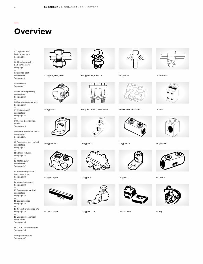
—01 Copper split-bolt connectors See page 5—02 Aluminum split-bolt connectorsSee page 7—03 Service post connectorsSee page 9—04 ViceLockSee page 11—05 Insulation piercing connectorsSee page 12—06 Two-bolt connectors See page 13—07 CSB and AMT connectors See page 15—08 Power distribution blocks See page 23—09 Dual-rated mechanical connectors See page 26—10 Dual-rated mechanical connectors See page 31—11 Splicer reducerSee page 32—12 Rectangular connectorsSee page 32—13 Aluminum parallel tap connectorsSee page 33—14 Insulating coversSee page 33—15 Copper mechanical connectorsSee page 34—16 Copper spliceSee page 34—17 Direct-burial splice kitsSee page 35—18 Copper mechanical connectorsSee page 35—19 LOCKTITE connectorsSee page 36—20 Tap connectorsSee page 42
5SPL IT- B O LT CO N N EC TO R S
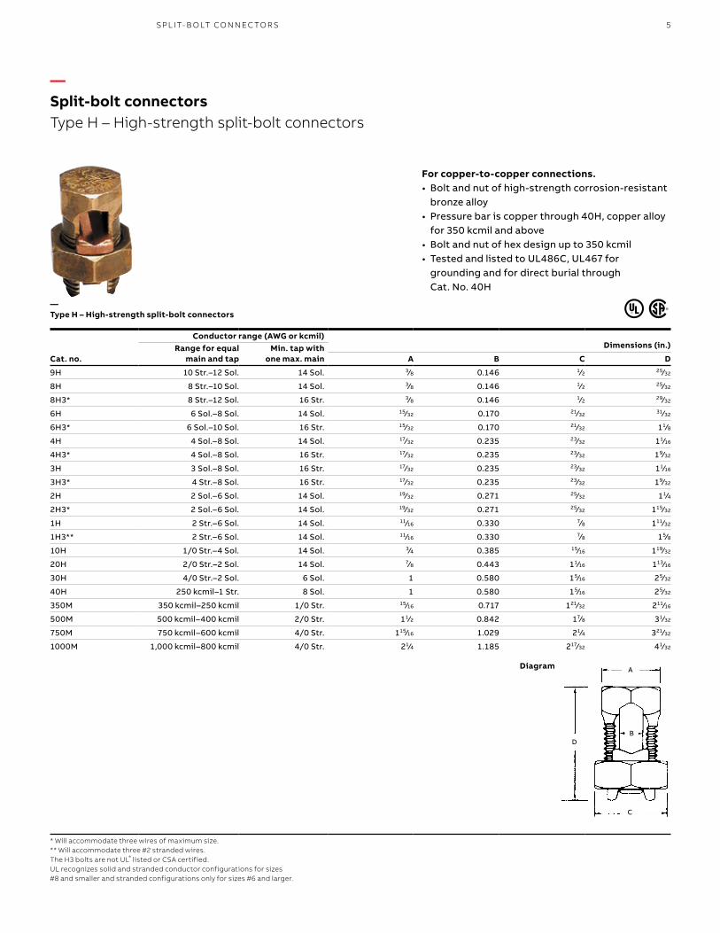
For copper-to-copper connections.• Bolt and nut of high-strength corrosion-resistant
bronze alloy• Pressure bar is copper through 40H, copper alloy
for 350 kcmil and above• Bolt and nut of hex design up to 350 kcmil• Tested and listed to UL486C, UL467 for
grounding and for direct burial through Cat. No. 40H
Cat. no.
Conductor range (AWG or kcmil)Dimensions (in.)Range for equal
main and tapMin. tap with
one max. main A B C D
9H 10 Str.–12 Sol. 14 Sol. 3⁄8 0.146 1⁄2 25⁄32
8H 8 Str.–10 Sol. 14 Sol. 3⁄8 0.146 1⁄2 25⁄32
8H3* 8 Str.–12 Sol. 16 Str. 3⁄8 0.146 1⁄2 29⁄32
6H 6 Sol.–8 Sol. 14 Sol. 15⁄32 0.170 21⁄32 31⁄32
6H3* 6 Sol.–10 Sol. 16 Str. 15⁄32 0.170 21⁄32 11⁄8
4H 4 Sol.–8 Sol. 14 Sol. 17⁄32 0.235 23⁄32 11⁄16
4H3* 4 Sol.–8 Sol. 16 Str. 17⁄32 0.235 23⁄32 19⁄32
3H 3 Sol.–8 Sol. 16 Str. 17⁄32 0.235 23⁄32 11⁄16
3H3* 4 Str.–8 Sol. 16 Str. 17⁄32 0.235 23⁄32 19⁄32
2H 2 Sol.–6 Sol. 14 Sol. 19⁄32 0.271 25⁄32 11⁄4
2H3* 2 Sol.–6 Sol. 14 Sol. 19⁄32 0.271 25⁄32 115⁄32
1H 2 Str.–6 Sol. 14 Sol. 11⁄16 0.330 7⁄8 111⁄32
1H3** 2 Str.–6 Sol. 14 Sol. 11⁄16 0.330 7⁄8 15⁄8
10H 1/0 Str.–4 Sol. 14 Sol. 3⁄4 0.385 15⁄16 119⁄32
20H 2/0 Str.–2 Sol. 14 Sol. 7⁄8 0.443 11⁄16 113⁄16
30H 4/0 Str.–2 Sol. 6 Sol. 1 0.580 15⁄16 25⁄32
40H 250 kcmil–1 Str. 8 Sol. 1 0.580 15⁄16 25⁄32
350M 350 kcmil–250 kcmil 1/0 Str. 15⁄16 0.717 121⁄32 211⁄16
500M 500 kcmil–400 kcmil 2/0 Str. 11⁄2 0.842 17⁄8 31⁄32
750M 750 kcmil–600 kcmil 4/0 Str. 115⁄16 1.029 21⁄4 321⁄32
1000M 1,000 kcmil–800 kcmil 4/0 Str. 21⁄4 1.185 217⁄32 41⁄32
* Will accommodate three wires of maximum size.** Will accommodate three #2 stranded wires.The H3 bolts are not UL® listed or CSA certified.UL recognizes solid and stranded conductor configurations for sizes #8 and smaller and stranded configurations only for sizes #6 and larger.
B
A
C
D
—Split-bolt connectorsType H – High-strength split-bolt connectors
—Type H – High-strength split-bolt connectors
Diagram
6 B L ACK B U R N M ECH A N I C A L CO N N EC TO R S
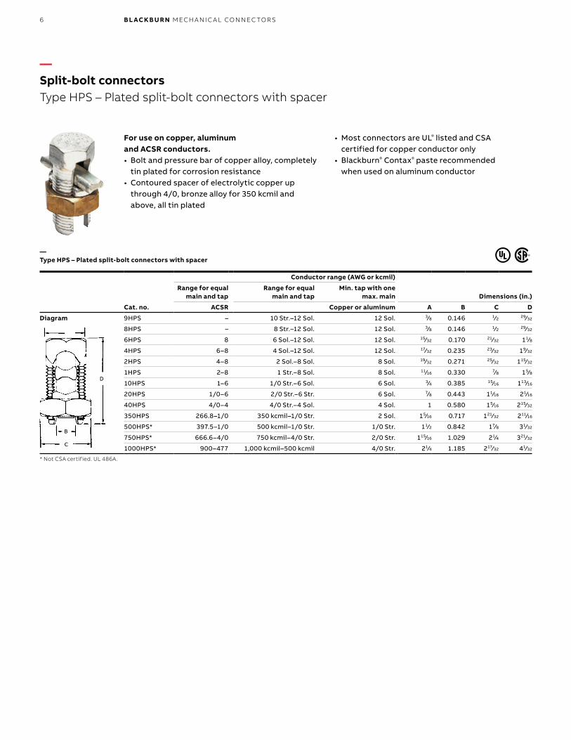
For use on copper, aluminum and ACSR conductors.• Bolt and pressure bar of copper alloy, completely
tin plated for corrosion resistance• Contoured spacer of electrolytic copper up
through 4/0, bronze alloy for 350 kcmil and above, all tin plated
• Most connectors are UL® listed and CSA certified for copper conductor only
• Blackburn® Contax® paste recommended when used on aluminum conductor
Cat. no.
Conductor range (AWG or kcmil)
Range for equal main and tap
Range for equal main and tap
Min. tap with one max. main Dimensions (in.)
ACSR Copper or aluminum A B C D
Diagram 9HPS – 10 Str.–12 Sol. 12 Sol. 3⁄8 0.146 1⁄2 29⁄32
8HPS – 8 Str.–12 Sol. 12 Sol. 3⁄8 0.146 1⁄2 29⁄32
6HPS 8 6 Sol.–12 Sol. 12 Sol. 15⁄32 0.170 21⁄32 11⁄8
4HPS 6–8 4 Sol.–12 Sol. 12 Sol. 17⁄32 0.235 23⁄32 19⁄32
2HPS 4–8 2 Sol.–8 Sol. 8 Sol. 19⁄32 0.271 25⁄32 115⁄32
1HPS 2–8 1 Str.–8 Sol. 8 Sol. 11⁄16 0.330 7⁄8 15⁄8
10HPS 1–6 1/0 Str.–6 Sol. 6 Sol. 3⁄4 0.385 15⁄16 113⁄16
20HPS 1/0–6 2/0 Str.–6 Str. 6 Sol. 7⁄8 0.443 11⁄16 21⁄16
40HPS 4/0–4 4/0 Str.–4 Sol. 4 Sol. 1 0.580 15⁄16 215⁄32
350HPS 266.8–1/0 350 kcmil–1/0 Str. 2 Sol. 15⁄16 0.717 121⁄32 211⁄16
500HPS* 397.5–1/0 500 kcmil–1/0 Str. 1/0 Str. 11⁄2 0.842 17⁄8 31⁄32
750HPS* 666.6–4/0 750 kcmil–4/0 Str. 2/0 Str. 115⁄16 1.029 21⁄4 321⁄32
1000HPS* 900–477 1,000 kcmil–500 kcmil 4/0 Str. 21⁄4 1.185 217⁄32 41⁄32
* Not CSA certified. UL 486A.
B
D
C
—Type HPS – Plated split-bolt connectors with spacer
—Split-bolt connectorsType HPS – Plated split-bolt connectors with spacer
7
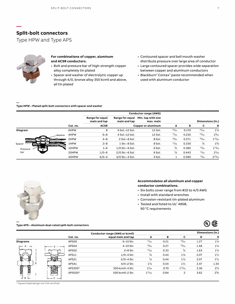
For combinations of copper, aluminum and ACSR conductors.• Bolt and pressure bar of high-strength copper
alloy completely tin plated• Spacer and washer of electrolytic copper up
through 4/0, bronze alloy 350 kcmil and above, all tin plated
• Contoured spacer and bell mouth washer distribute pressure over large area of conductor
• Large contoured spacer provides wide separation between copper and aluminum conductors
• Blackburn® Contax® paste recommended when used with aluminum conductor
Accommodates all aluminum and copper conductor combinations.• Six bolts cover range from #10 to 4/0 AWG• Install with standard wrenches• Corrosion-resistant tin-plated aluminum• Tested and listed to UL® 486B,
90 °C requirements
Cat. no.Conductor range (AWG or kcmil)
equal main and tap
Dimensions (in.)
A B C D E
Diagrams APS06 6–10 Str. 17⁄32 0.21 23⁄32 1.27 11⁄4
APS04 4–10 Str. 19⁄32 0.27 25⁄32 1.48 11⁄4
APS02 2–8 Str. 11⁄16 0.33 7⁄8 1.63 11⁄4
APS11 1/0–4 Str. 7⁄8 0.44 11⁄8 2.07 11⁄2
APS21 2/0–4 Str. 7⁄8 0.44 11⁄8 2.07 11⁄2
APS41 4/0–2 Str. 11⁄8 0.54 11⁄2 2.47 1.55
APS350* 350 kcmil–4 Str. 17⁄16 0.70 111⁄16 3.36 21⁄4
APS500* 500 kcmil–2 Str. 111⁄16 0.84 2 3.62 25⁄8
* Square head design not CSA certified
Conductor range (AWG)
Dimensions (in.)Range for equal
main and tapRange for equal
main and tapMin. tap with one
max. main
Cat. no. ACSR Copper or aluminum A B C D
Diagram 6HPW 8 6 Sol.–12 Sol. 12 Sol. 15⁄32 0.170 21⁄32 11⁄8
4HPW 6–8 4 Sol.–12 Sol. 12 Sol. 17⁄32 0.235 23⁄32 19⁄32
2HPW 4–8 2 Sol.–8 Sol. 8 Sol. 19⁄32 0.271 25⁄32 115⁄32
1HPW 2–8 1 Str.–8 Sol. 8 Sol. 11⁄16 0.330 7⁄8 15⁄8
10HPW 1–6 1/0 Str.–6 Sol. 6 Sol. 3⁄4 0.385 15⁄16 113⁄16
20HPW 1/0–6 2/0 Str.–6 Sol. 6 Sol. 7⁄8 0.443 11⁄16 21⁄16
40HPW 4/0–4 4/0 Str.–4 Sol. 4 Sol. 1 0.580 15⁄16 215⁄32
Washer
Spacer
Pressure bar
A
D
B
E
C
—Split-bolt connectorsType HPW and Type APS
—Type HPW – Plated split-bolt connectors with spacer and washer
—Type APS – Aluminum dual-rated split-bolt connectors
SPL IT- B O LT CO N N EC TO R S
8 B L ACK B U R N M ECH A N I C A L CO N N EC TO R S
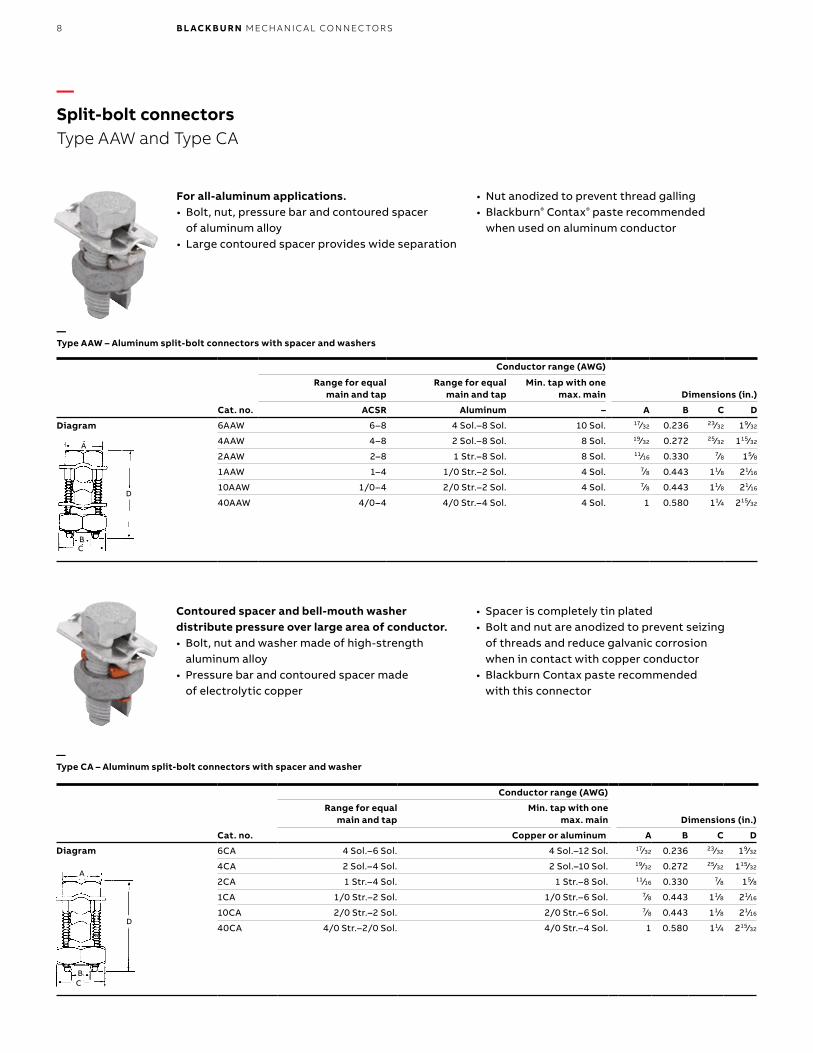
For all-aluminum applications.• Bolt, nut, pressure bar and contoured spacer
of aluminum alloy• Large contoured spacer provides wide separation
• Nut anodized to prevent thread galling• Blackburn® Contax® paste recommended
when used on aluminum conductor
Cat. no.
Conductor range (AWG)
Dimensions (in.)Range for equal
main and tapRange for equal
main and tapMin. tap with one
max. main
ACSR Aluminum – A B C D
6AAW 6–8 4 Sol.–8 Sol. 10 Sol. 17⁄32 0.236 23⁄32 19⁄32
4AAW 4–8 2 Sol.–8 Sol. 8 Sol. 19⁄32 0.272 25⁄32 115⁄32
2AAW 2–8 1 Str.–8 Sol. 8 Sol. 11⁄16 0.330 7⁄8 15⁄8
1AAW 1–4 1/0 Str.–2 Sol. 4 Sol. 7⁄8 0.443 11⁄8 21⁄16
10AAW 1/0–4 2/0 Str.–2 Sol. 4 Sol. 7⁄8 0.443 11⁄8 21⁄16
40AAW 4/0–4 4/0 Str.–4 Sol. 4 Sol. 1 0.580 11⁄4 215⁄32
Contoured spacer and bell-mouth washer distribute pressure over large area of conductor.• Bolt, nut and washer made of high-strength
aluminum alloy• Pressure bar and contoured spacer made
of electrolytic copper
• Spacer is completely tin plated• Bolt and nut are anodized to prevent seizing
of threads and reduce galvanic corrosion when in contact with copper conductor
• Blackburn Contax paste recommended with this connector
Cat. no.
Conductor range (AWG)
Range for equal main and tap
Min. tap with one max. main Dimensions (in.)
Copper or aluminum A B C D
6CA 4 Sol.–6 Sol. 4 Sol.–12 Sol. 17⁄32 0.236 23⁄32 19⁄32
4CA 2 Sol.–4 Sol. 2 Sol.–10 Sol. 19⁄32 0.272 25⁄32 115⁄32
2CA 1 Str.–4 Sol. 1 Str.–8 Sol. 11⁄16 0.330 7⁄8 15⁄8
1CA 1/0 Str.–2 Sol. 1/0 Str.–6 Sol. 7⁄8 0.443 11⁄8 21⁄16
10CA 2/0 Str.–2 Sol. 2/0 Str.–6 Sol. 7⁄8 0.443 11⁄8 21⁄16
40CA 4/0 Str.–2/0 Sol. 4/0 Str.–4 Sol. 1 0.580 11⁄4 215⁄32
A
D
BC
BC
D
A
—Split-bolt connectorsType AAW and Type CA
—Type AAW – Aluminum split-bolt connectors with spacer and washers
—Type CA – Aluminum split-bolt connectors with spacer and washer
Diagram
Diagram
9
— 01
— 02
— 04
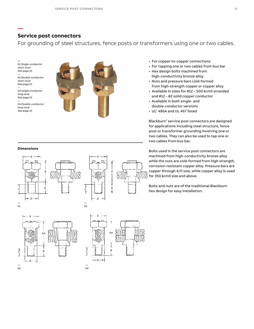
• For copper-to-copper connections• For tapping one or two cables from bus bar• Hex design bolts machined from
high-conductivity bronze alloy• Nuts and pressure bars cold-formed
from high-strength copper or copper alloy• Available in sizes for #12 – 500 kcmil stranded
and #12 – #2 solid copper conductor• Available in both single- and
double-conductor versions• UL® 486A and UL 467 listed
Blackburn® service post connectors are designed for applications including steel structure, fence post or transformer grounding involving one or two cables. They can also be used to tap one or two cables from bus bar.
Bolts used in the service post connectors are machined from high-conductivity bronze alloy while the nuts are cold-formed from high strength, corrosion-resistant copper alloy. Pressure bars are copper through 4/0 size, while copper alloy is used for 350 kcmil size and above.
Bolts and nuts are of the traditional Blackburn hex design for easy installation.
C B
A
E
D
AA
E
BC
D
AA
E
BC
D
— 03
B
A
E
C
D
—Service post connectorsFor grounding of steel structures, fence posts or transformers using one or two cables.
—01 Single-conductorshort stud See page 10—02 Double-conductorshort stud See page 10—03 Single-conductorlong studSee page 10—04 Double-conductorlong stud See page 10
C
Dimensions
SER V I CE P OS T CO N N EC TO R S
10 B L ACK B U R N M ECH A N I C A L CO N N EC TO R S
—Service post connectorsSingle- and double-conductor service post connectors, short stud and long stud
—Single- and double-conductor service post connectors, short stud
Cat. no.
Conductor range AWG (mm2)
Diameter range (in.) Stud size
Dimensions (in.)Stranded Solid
SP-DS SP-SS Max. Min. Max. Min. A AA B C D E
SP0DS SP0SS 8(6)
12(4)
8(10)
12(4)
0.146–0.081–
1⁄4–20 x 1⁄2 11⁄16 13⁄16 1⁄2 55⁄64 15⁄32 1⁄2
SP1DS SP1SS 7(10)
10(6)
6(10)
10(6)
0.164–0.102–
1⁄4–20 x 1⁄2 13⁄16 31⁄32 1⁄2 55⁄64 15⁄32 21⁄32
SP2DS SP2SS 5(16)
10(6)
4–
10–
0.206–0.102–
5⁄16–18 x 5⁄8 15⁄16 11⁄8 5⁄8 53⁄64 17⁄32 23⁄32
SP3DS SP3SS 3(25)
10(6)
2–
10–
0.26–0.102–
3⁄8–16 x 5⁄8 1⁄2 11⁄4 5⁄8 61⁄64 5⁄8 25⁄32
SP4DS SP4SS 1(35)
8(10)
2–
8–
0.332–0.129–
3⁄8–16 x 5⁄8 11⁄16 13⁄8 5⁄8 61⁄64 11⁄16 7⁄8
SP5DS SP5SS 1/0(50)
2(35)
1/0–
2–
0.373–0.258–
1⁄2–13 x 3⁄4 11⁄4 119⁄32 3⁄4 15⁄64 3⁄4 15⁄16
SP6DS SP6SS 2/0(50)
2(35)
2/0–
2–
0.419–0.258–
1⁄2–13 x 3⁄4 113⁄32 113⁄16 3⁄4 15⁄64 7⁄8 11⁄16
SP8DS SP8SS 4/0(95)
2(35)
4/0–
1–
0.528–0.289–
5⁄8–11 x 1 19⁄16 21⁄16 1 119⁄64 1 15⁄16
SP9DS SP9SS 350(150)
1/0(50)
––
––
0.681–0.373–
5⁄8–11 x 1 2 23⁄4 11⁄4 119⁄64 15⁄16 111⁄16
SP10DS SP10SS 500(240
3/0(95)
––
––
0.814–0.47–
3⁄4–10 x 11⁄4 21⁄4 31⁄8 13⁄4 131⁄64 11⁄2 17⁄8
—Single- and double-conductor service post connectors, long stud
Cat no.
Conductor range AWG (mm2)
Diameter range (in.) Stud size
Dimensions (in.)Stranded Solid
SP-SL SP-DL Max. Min. Max. Min. A AA B C D E
SP0SL SP0DL 8(6)
12(4)
8(10)
12(4)
0.146–0.081–
1⁄4–20 x 1 11⁄16 13⁄16 1 55⁄64 15⁄32 1⁄2
SP1SL SP1DL 7(10)
10(6)
6(10)
10(6)
0.164–0.102–
1⁄4–20 x 1 13⁄16 31⁄32 1 55⁄64 15⁄32 21⁄32
SP2SL SP2DL 5(16)
10(6)
4–
10–
0.206–0.102–
5⁄16–18 x 1 15⁄16 11⁄8 1 53⁄64 17⁄32 23⁄32
SP3SL SP3DL 3(25)
10(6)
2–
10–
0.26–0.102–
3⁄8–16 x 11⁄8 1 11⁄4 11⁄8 61⁄64 5⁄8 25⁄32
SP4SL SP4DL 1(35)
8(10)
2–
8–
0.332–0.129–
3⁄8–16 x 11⁄8 11⁄16 13⁄8 11⁄8 61⁄64 11⁄16 7⁄8
SP5SL SP5DL 1/0(50)
2(35)
1/0–
2–
0.373–0.258–
1⁄2–13 x 11⁄4 11⁄4 119⁄32 11⁄4 15⁄64 3⁄4 15⁄16
SP6SL SP6DL 2/0(50)
2(35)
2/0–
2–
0.419–0.258–
1⁄2–13 x 11⁄4 113⁄32 113⁄16 11⁄4 15⁄64 7⁄8 11⁄16
SP8SL SP8DL 4/0(95)
2(35)
4/0–
1–
0.528–0.289–
5⁄8–11 x 11⁄2 19⁄16 21⁄16 11⁄2 119⁄64 1 15⁄16
SP9SL SP9DL 350(150)
1/0(50)
––
––
0.681–0.373–
5⁄8–11 x 11⁄2 2 23⁄4 11⁄2 119⁄64 15⁄16 111⁄16
SP10SL SP10DL 500(240)
3/0(95)
––
––
0.814–0.47–
3⁄4–10 x 13⁄4 21⁄4 31⁄8 11⁄2 131⁄64 11⁄2 17⁄8
11PA R A L L EL G R O OV E CO N N EC TO R S
Cat. no.
2 Conductors wire range* Inner ctn. qty.
Master ctn. qty.
Competitor cross ref.
Max. Min. Decimal (in.) Fargo Reliable
VGC68 #6 Sol. #10 Sol. 0.162–0.101 50 250 GC-5006 BVC-6
VGC68SH #6 Sol. #10 Sol. 0.162–0.101 50 250 GC-5006SH –
VGC44 #4 Str. #8 Sol. 0.232–0.128 50 250 GC-5004 BVC-4
VGC23 #2 Sol. #6 Sol. 0.286–0.162 50 250 GC-5002 BVC-2
VGC12 #2 Str. #5 Sol. 0.320–0.181 50 250 GC-5002S BVC-2S
VGC2010 1/0 Str. #4 Sol. 0.390–0.204 50 250 GC-5020 BVC-20
VGC3020 2/0 Str. #3 Sol. 0.438–0.229 25 125 GC-5020S BVC-20S
VGC4040 4/0 Str. #1 Sol. 0.552–0.289 25 125 GC-5040 BVC-40
* Wire range indicates each connector’s ability to accommodate two wires of the same size shown in the “Max.” or “Min.” columns.
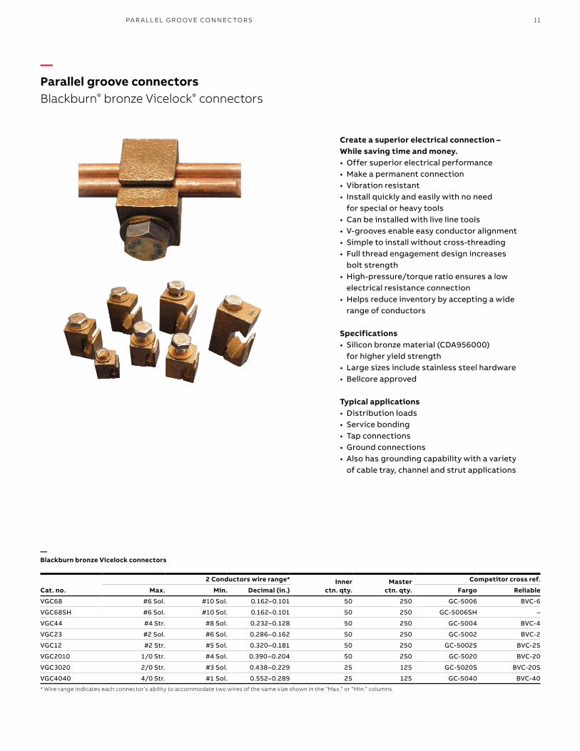
—Parallel groove connectorsBlackburn® bronze Vicelock® connectors
Create a superior electrical connection – While saving time and money.• Offer superior electrical performance• Make a permanent connection• Vibration resistant• Install quickly and easily with no need
for special or heavy tools• Can be installed with live line tools• V-grooves enable easy conductor alignment• Simple to install without cross-threading• Full thread engagement design increases
bolt strength• High-pressure/torque ratio ensures a low
electrical resistance connection• Helps reduce inventory by accepting a wide
range of conductors
Specifications• Silicon bronze material (CDA956000)
for higher yield strength• Large sizes include stainless steel hardware• Bellcore approved
Typical applications• Distribution loads• Service bonding• Tap connections• Ground connections• Also has grounding capability with a variety
of cable tray, channel and strut applications
—Blackburn bronze Vicelock connectors
12 B L ACK B U R N M ECH A N I C A L CO N N EC TO R S
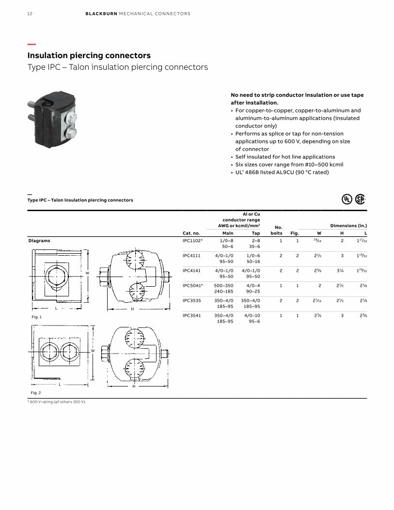
No need to strip conductor insulation or use tape after installation.• For copper-to-copper, copper-to-aluminum and
aluminum-to-aluminum applications (insulated conductor only)
• Performs as splice or tap for non-tension applications up to 600 V, depending on size of connector
• Self insulated for hot line applications• Six sizes cover range from #10–500 kcmil• UL® 486B listed AL9CU (90 °C rated)
Cat. no.
Al or Cuconductor range
AWG or kcmil/mm2No.
bolts Fig.
Dimensions (in.)
Main Tap W H L
Diagrams
L
W
H
L
W
H
Fig. 1
Fig. 2
IPC1102* 1/0–850–6
2–835–6
1 1 29⁄16 2 117⁄32
IPC4111 4/0–1/095–50
1/0–650–16
2 2 21⁄2 3 119⁄32
IPC4141 4/0–1/095–50
4/0–1/095–50
2 2 25⁄8 31⁄4 129⁄32
IPC5041* 500–350240–185
4/0–490–25
1 1 2 21⁄2 21⁄8
IPC3535 350–4/0185–95
350–4/0185–95
2 2 21⁄16 21⁄2 21⁄8
IPC3541 350–4/0185–95
4/0–1095–6
1 1 23⁄4 3 25⁄8
* 600 V rating (all others 300 V).
—Insulation piercing connectorsType IPC – Talon insulation piercing connectors
—Type IPC – Talon insulation piercing connectors
13
Cat. no.
Conductor range (AWG or kcmil) Conductor diameter (B)
Bolt head
Dimensions (in.)Main Tap
Max. Min. Max. Min. Max. Min. L H D
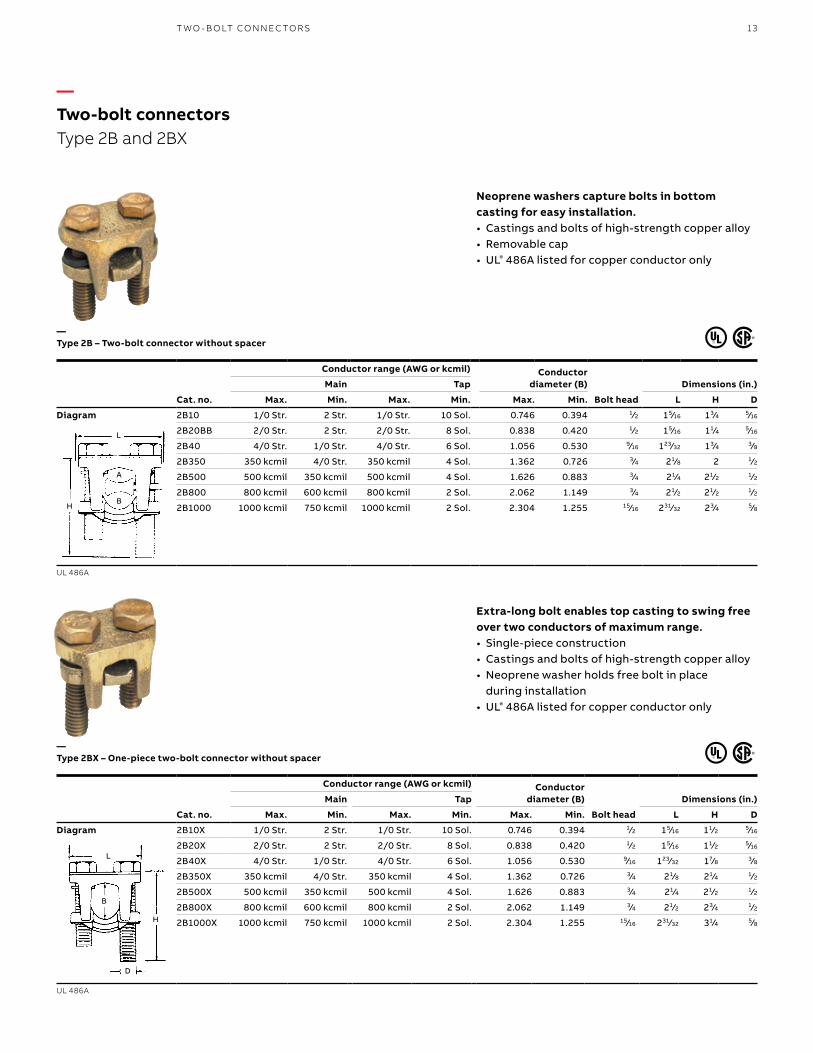
Diagram 2B10 1/0 Str. 2 Str. 1/0 Str. 10 Sol. 0.746 0.394 1⁄2 15⁄16 13⁄4 5⁄16
2B20BB 2/0 Str. 2 Str. 2/0 Str. 8 Sol. 0.838 0.420 1⁄2 15⁄16 11⁄4 5⁄16
2B40 4/0 Str. 1/0 Str. 4/0 Str. 6 Sol. 1.056 0.530 9⁄16 123⁄32 13⁄4 3⁄8
2B350 350 kcmil 4/0 Str. 350 kcmil 4 Sol. 1.362 0.726 3⁄4 21⁄8 2 1⁄2
2B500 500 kcmil 350 kcmil 500 kcmil 4 Sol. 1.626 0.883 3⁄4 21⁄4 21⁄2 1⁄2
2B800 800 kcmil 600 kcmil 800 kcmil 2 Sol. 2.062 1.149 3⁄4 21⁄2 21⁄2 1⁄2
2B1000 1000 kcmil 750 kcmil 1000 kcmil 2 Sol. 2.304 1.255 15⁄16 231⁄32 23⁄4 5⁄8
UL 486A
Extra-long bolt enables top casting to swing free over two conductors of maximum range.• Single-piece construction• Castings and bolts of high-strength copper alloy• Neoprene washer holds free bolt in place
during installation• UL® 486A listed for copper conductor only
Neoprene washers capture bolts in bottom casting for easy installation.• Castings and bolts of high-strength copper alloy• Removable cap• UL® 486A listed for copper conductor only
Cat. no.
Conductor range (AWG or kcmil) Conductor diameter (B)
Bolt head
Dimensions (in.)Main Tap
Max. Min. Max. Min. Max. Min. L H D
Diagram 2B10X 1/0 Str. 2 Str. 1/0 Str. 10 Sol. 0.746 0.394 1⁄2 15⁄16 11⁄2 5⁄16
2B20X 2/0 Str. 2 Str. 2/0 Str. 8 Sol. 0.838 0.420 1⁄2 15⁄16 11⁄2 5⁄16
2B40X 4/0 Str. 1/0 Str. 4/0 Str. 6 Sol. 1.056 0.530 9⁄16 123⁄32 17⁄8 3⁄8
2B350X 350 kcmil 4/0 Str. 350 kcmil 4 Sol. 1.362 0.726 3⁄4 21⁄8 21⁄4 1⁄2
2B500X 500 kcmil 350 kcmil 500 kcmil 4 Sol. 1.626 0.883 3⁄4 21⁄4 21⁄2 1⁄2
2B800X 800 kcmil 600 kcmil 800 kcmil 2 Sol. 2.062 1.149 3⁄4 21⁄2 23⁄4 1⁄2
2B1000X 1000 kcmil 750 kcmil 1000 kcmil 2 Sol. 2.304 1.255 15⁄16 231⁄32 31⁄4 5⁄8
UL 486A
BH
L
A
L
B
H
D
—Two-bolt connectorsType 2B and 2BX
—Type 2B – Two-bolt connector without spacer
—Type 2BX – One-piece two-bolt connector without spacer
T WO - B O LT CO N N EC TO R S
14 B L ACK B U R N M ECH A N I C A L CO N N EC TO R S
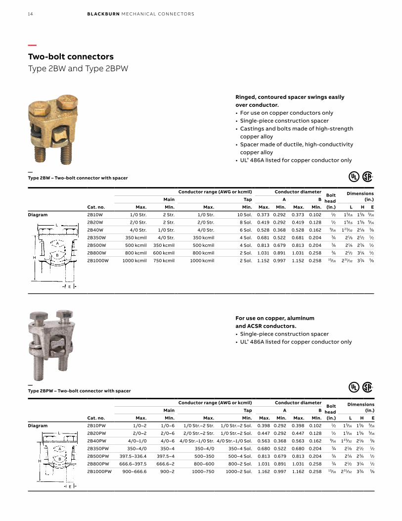
Ringed, contoured spacer swings easily over conductor.• For use on copper conductors only• Single-piece construction spacer• Castings and bolts made of high-strength
copper alloy• Spacer made of ductile, high-conductivity
copper alloy• UL® 486A listed for copper conductor only
For use on copper, aluminum and ACSR conductors.• Single-piece construction spacer• UL® 486A listed for copper conductor only
Cat. no.
Conductor range (AWG or kcmil) Conductor diameterBolt
head (in.)
Dimensions (in.)Main Tap A B
Max. Min. Max. Min. Max. Min. Max. Min. L H E
Diagram 2B10W 1/0 Str. 2 Str. 1/0 Str. 10 Sol. 0.373 0.292 0.373 0.102 1⁄2 15⁄16 15⁄8 5⁄16
2B20W 2/0 Str. 2 Str. 2/0 Str. 8 Sol. 0.419 0.292 0.419 0.128 1⁄2 15⁄16 15⁄8 5⁄16
2B40W 4/0 Str. 1/0 Str. 4/0 Str. 6 Sol. 0.528 0.368 0.528 0.162 9⁄16 123⁄32 21⁄8 3⁄8
2B350W 350 kcmil 4/0 Str. 350 kcmil 4 Sol. 0.681 0.522 0.681 0.204 3⁄4 21⁄8 21⁄2 1⁄2
2B500W 500 kcmil 350 kcmil 500 kcmil 4 Sol. 0.813 0.679 0.813 0.204 3⁄4 21⁄4 23⁄4 1⁄2
2B800W 800 kcmil 600 kcmil 800 kcmil 2 Sol. 1.031 0.891 1.031 0.258 3⁄4 21⁄2 31⁄4 1⁄2
2B1000W 1000 kcmil 750 kcmil 1000 kcmil 2 Sol. 1.152 0.997 1.152 0.258 15⁄16 231⁄32 33⁄4 5⁄8
Cat. no.
Conductor range (AWG or kcmil) Conductor diameterBolt
head (in.)
Dimensions (in.)Main Tap A B
Max. Min. Max. Min. Max. Min. Max. Min. L H E
Diagram 2B10PW 1/0–2 1/0–6 1/0 Str.–2 Str. 1/0 Str.–2 Sol. 0.398 0.292 0.398 0.102 1⁄2 15⁄16 15⁄8 5⁄16
2B20PW 2/0–2 2/0–6 2/0 Str.–2 Str. 1/0 Str.–2 Sol. 0.447 0.292 0.447 0.128 1⁄2 15⁄16 15⁄8 5⁄16
2B40PW 4/0–1/0 4/0–6 4/0 Str.–1/0 Str. 4/0 Str.–1/0 Sol. 0.563 0.368 0.563 0.162 9⁄16 123⁄32 21⁄8 3⁄8
2B350PW 350–4/0 350–4 350–4/0 350–4 Sol. 0.680 0.522 0.680 0.204 3⁄4 21⁄8 21⁄2 1⁄2
2B500PW 397.5–336.4 397.5–4 500–350 500–4 Sol. 0.813 0.679 0.813 0.204 3⁄4 21⁄4 23⁄4 1⁄2
2B800PW 666.6–397.5 666.6–2 800–600 800–2 Sol. 1.031 0.891 1.031 0.258 3⁄4 21⁄2 31⁄4 1⁄2
2B1000PW 900–666.6 900–2 1000–750 1000–2 Sol. 1.162 0.997 1.162 0.258 15⁄16 231⁄32 33⁄4 5⁄8
A
B
L
H
E
A
B
L
H
E
—Two-bolt connectorsType 2BW and Type 2BPW
—Type 2BW – Two-bolt connector with spacer
—Type 2BPW – Two-bolt connector with spacer
15
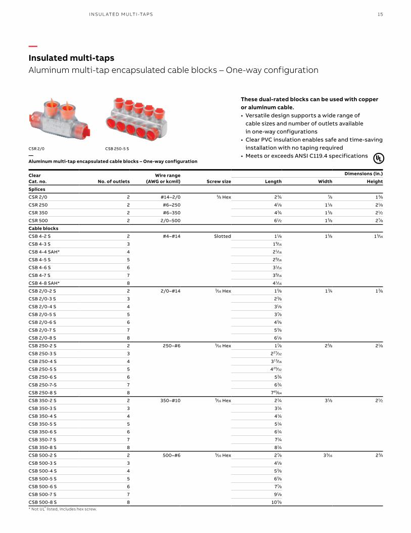
Clear Cat. no. No. of outlets
Wire range (AWG or kcmil) Screw size
Dimensions (in.)
Length Width Height
Splices
CSR 2/0 2 #14–2/0 3⁄8 Hex 23⁄4 7⁄8 13⁄8
CSR 250 2 #6–250 41⁄8 11⁄8 21⁄8
CSR 350 2 #6–350 43⁄4 13⁄8 21⁄2
CSR 500 2 2/0–500 61⁄2 15⁄8 27⁄8
Cable blocks
CSB 4-2 S 2 #4–#14 Slotted 11⁄8 15⁄8 15⁄16
CSB 4-3 S 3 19⁄16
CSB 4-4 SAH* 4 21⁄16
CSB 4-5 S 5 29⁄16
CSB 4-6 S 6 31⁄16
CSB 4-7 S 7 39⁄16
CSB 4-8 SAH* 8 41⁄16
CSB 2/0-2 S 2 2/0–#14 3⁄16 Hex 15⁄8 13⁄4 13⁄8
CSB 2/0-3 S 3 23⁄8
CSB 2/0-4 S 4 31⁄8
CSB 2/0-5 S 5 37⁄8
CSB 2/0-6 S 6 45⁄8
CSB 2/0-7 S 7 53⁄8
CSB 2/0-8 S 8 61⁄8
CSB 250-2 S 2 250–#6 5⁄16 Hex 17⁄8 25⁄8 21⁄8
CSB 250-3 S 3 227⁄32
CSB 250-4 S 4 313⁄16
CSB 250-5 S 5 425⁄32
CSB 250-6 S 6 53⁄4
CSB 250-7-S 7 63⁄4
CSB 250-8 S 8 745⁄64
CSB 350-2 S 2 350–#10 5⁄16 Hex 21⁄4 31⁄8 21⁄2
CSB 350-3 S 3 31⁄4
CSB 350-4 S 4 41⁄4
CSB 350-5 S 5 51⁄4
CSB 350-6 S 6 61⁄4
CSB 350-7 S 7 71⁄4
CSB 350-8 S 8 81⁄4
CSB 500-2 S 2 500–#6 5⁄16 Hex 27⁄8 33⁄16 23⁄4
CSB 500-3 S 3 41⁄8
CSB 500-4 S 4 53⁄8
CSB 500-5 S 5 65⁄8
CSB 500-6 S 6 77⁄8
CSB 500-7 S 7 91⁄8
CSB 500-8 S 8 103⁄8* Not UL® listed, includes hex screw.
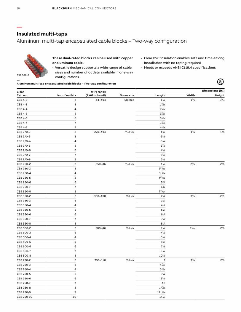
These dual-rated blocks can be used with copper or aluminum cable.• Versatile design supports a wide range of
cable sizes and number of outlets available in one-way configurations
• Clear PVC insulation enables safe and time-saving installation with no taping required
• Meets or exceeds ANSI C119.4 specificationsCSB 250-5 SCSR 2/0
—Insulated multi-tapsAluminum multi-tap encapsulated cable blocks – One-way configuration
—Aluminum multi-tap encapsulated cable blocks – One-way configuration
I NSU L ATED M U LTI -TA P S
16 B L ACK B U R N M ECH A N I C A L CO N N EC TO R S
Clear Cat. no. No. of outlets
Wire range (AWG or kcmil) Screw size
Dimensions (in.)
Length Width Height
CSB 4-2 2 #4–#14 Slotted 11⁄8 15⁄8 15⁄16
CSB 4-3 3 19⁄16
CSB 4-4 4 21⁄16
CSB 4-5 5 29⁄16
CSB 4-6 6 31⁄16
CSB 4-7 7 39⁄16
CSB 4-8 8 41⁄16
CSB 2/0-2 2 2/0–#14 3⁄16 Hex 15⁄8 13⁄4 13⁄8
CSB 2/0-3 3 23⁄8
CSB 2/0-4 4 31⁄8
CSB 2/0-5 5 37⁄8
CSB 2/0-6 6 45⁄8
CSB 2/0-7 7 53⁄8
CSB 2/0-8 8 61⁄8
CSB 250-2 2 250–#6 5⁄16 Hex 17⁄8 25⁄8 21⁄8
CSB 250-3 3 227⁄32
CSB 250-4 4 313⁄16
CSB 250-5 5 425⁄32
CSB 250-6 6 53⁄4
CSB 250-7 7 63⁄4
CSB 250-8 8 745⁄64
CSB 350-2 2 350–#10 3⁄8 Hex 21⁄4 31⁄8 21⁄2
CSB 350-3 3 31⁄4
CSB 350-4 4 41⁄4
CSB 350-5 5 51⁄4
CSB 350-6 6 61⁄4
CSB 350-7 7 71⁄4
CSB 350-8 8 81⁄4
CSB 500-2 2 500–#6 3⁄8 Hex 27⁄8 33⁄16 23⁄4
CSB 500-3 3 41⁄8
CSB 500-4 4 53⁄8
CSB 500-5 5 65⁄8
CSB 500-6 6 77⁄8
CSB 500-7 7 91⁄8
CSB 500-8 8 103⁄8
CSB 750-2 2 750–1/0 3⁄8 Hex 3 33⁄8 21⁄4
CSB 750-3 3 47⁄16
CSB 750-4 4 53⁄16
CSB 750-5 5 71⁄4
CSB 750-6 6 85⁄8
CSB 750-7 7 10
CSB 750-8 8 117⁄16
CSB 750-9 9 1213⁄16
CSB 750-10 10 141⁄4
CSB 500-8
These dual-rated blocks can be used with copper or aluminum cable.• Versatile design supports a wide range of cable
sizes and number of outlets available in one-way configurations
• Clear PVC insulation enables safe and time-saving installation with no taping required
• Meets or exceeds ANSI C119.4 specifications
—Insulated multi-tapsAluminum multi-tap encapsulated cable blocks – Two-way configuration
—Aluminum multi-tap encapsulated cable blocks – Two-way configuration
17
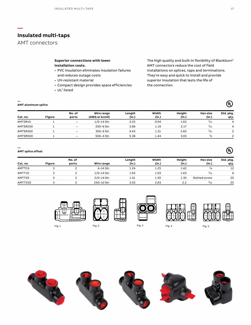
Superior connections with lower installation costs.• PVC insulation eliminates insulation failures
and reduces outage costs• UV-resistant material• Compact design provides space efficiencies• UL® listed
The high quality and built-in flexibility of Blackburn® AMT connectors reduce the cost of field installations on splices, taps and terminations. They’re easy and quick to install and provide superior insulation that lasts the life of the connection.
—AMT aluminum splice
Cat. no. FigureNo. of ports
Wire range (AWG or kcmil)
Length (in.)
Width (in.)
Height (in.)
Hex size (in.)
Std. pkg. qty.
AMTSR10 1 – 1/0–14 Str. 3.25 0.94 1.63 3⁄16 4
AMTSR250 1 – 250–6 Str. 3.96 1.19 2.17 5⁄16 4
AMTSR350 1 – 350–6 Str. 4.43 1.31 2.62 5⁄16 2
AMTSR500 1 – 500–4 Str. 5.38 1.44 3.03 3⁄8 2
Fig. 1 Fig. 3 Fig. 5Fig. 2 Fig. 4
—AMT splice offset
Cat. no. FigureNo. of ports Wire range
Length (in.)
Width (in.)
Height (in.)
Hex size (in.)
Std. pkg. qty.
AMTTC4 3 2 4–14 Str. 1.24 1.25 1.42 1⁄8 12
AMTT10 3 2 1/0–14 Str. 1.63 1.63 1.63 3⁄16 6
AMTT20 3 2 2/0–14 Str. 1.41 1.50 1.35 Slotted screw 25
AMTT250 3 2 250–10 Str. 2.03 2.63 2.2 5⁄16 25
—Insulated multi-tapsAMT connectors
I NSU L ATED M U LTI -TA P S
18 B L ACK B U R N M ECH A N I C A L CO N N EC TO R S
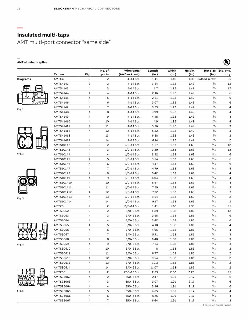
—AMT aluminum splice
Cat. no. Fig.No. of ports
Wire range (AWG or kcmil)
Length (in.)
Width (in.)
Height (in.)
Hex size (in.)
Std. pkg. qty.
Diagrams AMTC4 2 2 4–14 Str. 1.11 1.10 1.35 Slotted screw 25
AMTS4142 2 2 4–14 Str. 1.24 1.22 1.42 1⁄8 12
AMTS4143 4 3 4–14 Str. 1.7 1.22 1.42 1⁄8 12
AMTS4144 4 4 4–14 Str. 2.16 1.22 1.42 1⁄8 6
AMTS4145 4 5 4–14 Str. 2.61 1.22 1.42 1⁄8 6
AMTS4146 4 6 4–14 Str. 3.07 1.22 1.42 1⁄8 6
AMTS4147 4 7 4–14 Str. 3.53 1.22 1.42 1⁄8 4
AMTS4148 4 8 4–14 Str. 3.99 1.22 1.42 1⁄8 4
AMTS4149 4 9 4–14 Str. 4.45 1.22 1.42 1⁄8 4
AMTS41410 4 10 4–14 Str. 4.9 1.22 1.42 1⁄8 4
AMTS41411 4 11 4–14 Str. 5.36 1.22 1.42 1⁄8 3
AMTS41412 4 12 4–14 Str. 5.82 1.22 1.42 1⁄8 3
AMTS41413 4 13 4–14 Str. 6.28 1.22 1.42 1⁄8 2
AMTS41414 4 14 4–14 Str. 6.74 1.22 1.42 1⁄8 2
AMTS10142 2 2 1/0–14 Str. 1.67 1.53 1.63 3⁄16 12
AMTS10143 4 3 1/0–14 Str. 2.29 1.53 1.63 3⁄16 12
AMTS10144 4 4 1/0–14 Str. 2.92 1.53 1.63 3⁄16 6
AMTS10145 4 5 1/0–14 Str. 3.54 1.53 1.63 3⁄16 6
AMTS10146 4 6 1/0–14 Str. 4.17 1.53 1.63 3⁄16 6
AMTS10147 4 7 1/0–14 Str. 4.79 1.53 1.63 3⁄16 4
AMTS10148 4 8 1/0–14 Str. 5.42 1.53 1.63 3⁄16 4
AMTS10149 4 9 1/0–14 Str. 6.04 1.53 1.63 3⁄16 4
AMTS101410 4 10 1/0–14 Str. 6.67 1.53 1.63 3⁄16 4
AMTS101411 4 11 1/0–14 Str. 7.29 1.53 1.63 3⁄16 3
AMTS101412 4 12 1/0–14 Str. 7.92 1.53 1.63 3⁄16 3
AMTS101413 4 13 1/0–14 Str. 8.54 1.53 1.63 3⁄16 2
AMTS101414 4 14 1/0–14 Str. 9.17 1.53 1.63 3⁄16 2
AMT20 2 2 2/0–14 Str. 1.41 1.10 1.35 5⁄16 25
AMTS3062 2 2 3/0–6 Str. 1.89 1.58 1.86 3⁄16 12
AMTS3063 4 3 3/0–6 Str. 2.65 1.58 1.86 3⁄16 6
AMTS3064 4 4 3/0–6 Str. 3.42 1.58 1.86 3⁄16 6
AMTS3065 4 5 3/0–6 Str. 4.18 1.58 1.86 3⁄16 4
AMTS3066 4 6 3/0–6 Str. 4.95 1.58 1.86 3⁄16 4
AMTS3067 4 7 3/0–6 Str. 5.71 1.58 1.86 3⁄16 3
AMTS3068 4 8 3/0–6 Str. 6.48 1.58 1.86 3⁄16 3
AMTS3069 4 9 3/0–6 Str. 7.24 1.58 1.86 3⁄16 3
AMTS30610 4 10 3/0–6 Str. 8 1.58 1.86 3⁄16 2
AMTS30611 4 11 3/0–6 Str. 8.77 1.58 1.86 3⁄16 2
AMTS30612 4 12 3/0–6 Str. 9.54 1.58 1.86 3⁄16 2
AMTS30613 4 13 3/0–6 Str. 10.3 1.58 1.86 3⁄16 2
AMTS30614 4 14 3/0–6 Str. 11.07 1.58 1.86 3⁄16 2
AMT250 2 2 250–10 Str. 2.03 2.00 2.20 5⁄16 25
AMTS25062 4 2 250–6 Str. 2.17 1.91 2.17 5⁄16 6
AMTS25063 4 3 250–6 Str. 3.07 1.91 2.17 5⁄16 6
AMTS25064 4 4 250–6 Str. 3.96 1.91 2.17 5⁄16 6
AMTS25065 4 5 250–6 Str. 4.85 1.91 2.17 5⁄16 4
AMTS25066 4 6 250–6 Str. 5.75 1.91 2.17 5⁄16 4
AMTS25067 4 7 250–6 Str. 6.64 1.91 2.17 5⁄16 3
Continued on next page
Fig. 1
Fig. 3
Fig. 5
—Insulated multi-tapsAMT multi-port connector “same side”
Fig. 2
Fig. 4
19
Fig. 1
Fig. 3
Fig. 5
Fig. 2
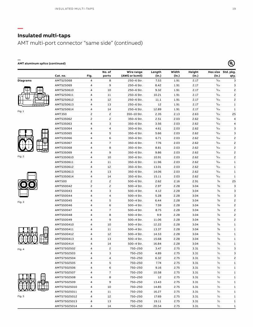
—AMT aluminum splice (continued)
Cat. no. Fig.No. ofports
Wire range (AWG or kcmil)
Length (in.)
Width (in.)
Height (in.)
Hex size (in.)
Std. pkg. qty.
Diagrams AMTS25068 4 8 250–6 Str. 7.53 1.91 2.17 5⁄16 3
AMTS25069 4 9 250–6 Str. 8.42 1.91 2.17 5⁄16 3
AMTS250610 4 10 250–6 Str. 9.32 1.91 2.17 5⁄16 2
AMTS250611 4 11 250–6 Str. 10.21 1.91 2.17 5⁄16 2
AMTS250612 4 12 250–6 Str. 11.1 1.91 2.17 5⁄16 2
AMTS250613 4 13 250–6 Str. 12 1.91 2.17 5⁄16 1
AMTS250614 4 14 250–6 Str. 12.89 1.91 2.17 5⁄16 1
AMT350 2 2 350–10 Str. 2.35 2.13 2.63 5⁄16 25
AMTS35062 2 2 350–6 Str. 2.51 2.03 2.62 5⁄16 4
AMTS35063 4 3 350–6 Str. 3.56 2.03 2.62 5⁄16 4
AMTS35064 4 4 350–6 Str. 4.61 2.03 2.62 5⁄16 3
AMTS35065 4 5 350–6 Str. 5.66 2.03 2.62 5⁄16 3
AMTS35066 4 6 350–6 Str. 6.71 2.03 2.62 5⁄16 2
AMTS35067 4 7 350–6 Str. 7.76 2.03 2.62 5⁄16 2
AMTS35068 4 8 350–6 Str. 8.81 2.03 2.62 5⁄16 2
AMTS35069 4 9 350–6 Str. 9.86 2.03 2.62 5⁄16 2
AMTS350610 4 10 350–6 Str. 10.91 2.03 2.62 5⁄16 2
AMTS350611 4 11 350–6 Str. 11.96 2.03 2.62 5⁄16 1
AMTS350612 4 12 350–6 Str. 13.01 2.03 2.62 5⁄16 1
AMTS350613 4 13 350–6 Str. 14.06 2.03 2.62 5⁄16 1
AMTS350614 4 14 350–6 Str. 15.11 2.03 2.62 5⁄16 1
AMT500 2 2 500–6 Str. 2.62 2.16 2.91 3⁄8 25
AMTS50042 2 2 500–4 Str. 2.97 2.28 3.04 3⁄8 3
AMTS50043 4 3 500–4 Str. 4.12 2.28 3.04 3⁄8 3
AMTS50044 4 4 500–4 Str. 5.28 2.28 3.04 3⁄8 3
AMTS50045 4 5 500–4 Str. 6.44 2.28 3.04 3⁄8 2
AMTS50046 4 6 500–4 Str. 7.59 2.28 3.04 3⁄8 2
AMTS50047 4 7 500–4 Str. 8.75 2.28 3.04 3⁄8 2
AMTS50048 4 8 500–4 Str. 9.9 2.28 3.04 3⁄8 2
AMTS50049 4 9 500–4 Str. 11.06 2.28 3.04 3⁄8 2
AMTS500410 4 10 500–4 Str. 12.22 2.28 3.04 3⁄8 1
AMTS500411 4 11 500–4 Str. 13.37 2.28 3.04 3⁄8 1
AMTS500412 4 12 500–4 Str. 14.53 2.28 3.04 3⁄8 1
AMTS500413 4 13 500–4 Str. 15.68 2.28 3.04 3⁄8 1
AMTS500414 4 14 500–4 Str. 16.84 2.28 3.04 3⁄8 1
AMTS7502502 4 2 750–250 3.47 2.75 3.31 1⁄2 3
AMTS7502503 4 3 750–250 4.89 2.75 3.31 1⁄2 3
AMTS7502504 4 4 750–250 6.32 2.75 3.31 1⁄2 2
AMTS7502505 4 5 750–250 7.74 2.75 3.31 1⁄2 1
AMTS7502506 4 6 750–250 9.16 2.75 3.31 1⁄2 1
AMTS7502507 4 7 750–250 10.58 2.75 3.31 1⁄2 1
AMTS7502508 4 8 750–250 12 2.75 3.31 1⁄2 1
AMTS7502509 4 9 750–250 13.43 2.75 3.31 1⁄2 1
AMTS75025010 4 10 750–250 14.85 2.75 3.31 1⁄2 1
AMTS75025011 4 11 750–250 16.27 2.75 3.31 1⁄2 1
AMTS75025012 4 12 750–250 17.69 2.75 3.31 1⁄2 1
AMTS75025013 4 13 750–250 19.11 2.75 3.31 1⁄2 1
AMTS75025014 4 14 750–250 20.54 2.75 3.31 1⁄2 1
—Insulated multi-tapsAMT multi-port connector “same side” (continued)
Fig. 4
I NSU L ATED M U LTI -TA P S
20 B L ACK B U R N M ECH A N I C A L CO N N EC TO R S
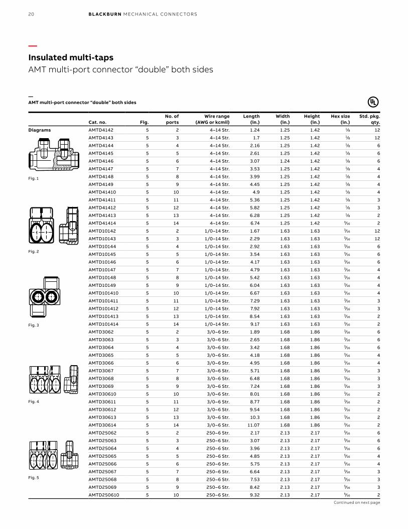
—AMT multi-port connector “double” both sides
Cat. no. Fig.No. ofports
Wire range (AWG or kcmil)
Length (in.)
Width (in.)
Height (in.)
Hex size (in.)
Std. pkg. qty.
Diagrams AMTD4142 5 2 4–14 Str. 1.24 1.25 1.42 1⁄8 12
AMTD4143 5 3 4–14 Str. 1.7 1.25 1.42 1⁄8 12
AMTD4144 5 4 4–14 Str. 2.16 1.25 1.42 1⁄8 6
AMTD4145 5 5 4–14 Str. 2.61 1.25 1.42 1⁄8 6
AMTD4146 5 6 4–14 Str. 3.07 1.24 1.42 1⁄8 6
AMTD4147 5 7 4–14 Str. 3.53 1.25 1.42 1⁄8 4
AMTD4148 5 8 4–14 Str. 3.99 1.25 1.42 1⁄8 4
AMTD4149 5 9 4–14 Str. 4.45 1.25 1.42 1⁄8 4
AMTD41410 5 10 4–14 Str. 4.9 1.25 1.42 1⁄8 4
AMTD41411 5 11 4–14 Str. 5.36 1.25 1.42 1⁄8 3
AMTD41412 5 12 4–14 Str. 5.82 1.25 1.42 1⁄8 3
AMTD41413 5 13 4–14 Str. 6.28 1.25 1.42 1⁄8 2
AMTD41414 5 14 4–14 Str. 6.74 1.25 1.42 3⁄16 2
AMTD10142 5 2 1/0–14 Str. 1.67 1.63 1.63 3⁄16 12
AMTD10143 5 3 1/0–14 Str. 2.29 1.63 1.63 3⁄16 12
AMTD10144 5 4 1/0–14 Str. 2.92 1.63 1.63 3⁄16 6
AMTD10145 5 5 1/0–14 Str. 3.54 1.63 1.63 3⁄16 6
AMTD10146 5 6 1/0–14 Str. 4.17 1.63 1.63 3⁄16 6
AMTD10147 5 7 1/0–14 Str. 4.79 1.63 1.63 3⁄16 4
AMTD10148 5 8 1/0–14 Str. 5.42 1.63 1.63 3⁄16 4
AMTD10149 5 9 1/0–14 Str. 6.04 1.63 1.63 3⁄16 4
AMTD101410 5 10 1/0–14 Str. 6.67 1.63 1.63 3⁄16 4
AMTD101411 5 11 1/0–14 Str. 7.29 1.63 1.63 3⁄16 3
AMTD101412 5 12 1/0–14 Str. 7.92 1.63 1.63 3⁄16 3
AMTD101413 5 13 1/0–14 Str. 8.54 1.63 1.63 3⁄16 2
AMTD101414 5 14 1/0–14 Str. 9.17 1.63 1.63 3⁄16 2
AMTD3062 5 2 3/0–6 Str. 1.89 1.68 1.86 3⁄16 6
AMTD3063 5 3 3/0–6 Str. 2.65 1.68 1.86 3⁄16 6
AMTD3064 5 4 3/0–6 Str. 3.42 1.68 1.86 3⁄16 6
AMTD3065 5 5 3/0–6 Str. 4.18 1.68 1.86 3⁄16 4
AMTD3066 5 6 3/0–6 Str. 4.95 1.68 1.86 3⁄16 4
AMTD3067 5 7 3/0–6 Str. 5.71 1.68 1.86 3⁄16 3
AMTD3068 5 8 3/0–6 Str. 6.48 1.68 1.86 3⁄16 3
AMTD3069 5 9 3/0–6 Str. 7.24 1.68 1.86 3⁄16 3
AMTD30610 5 10 3/0–6 Str. 8.01 1.68 1.86 3⁄16 2
AMTD30611 5 11 3/0–6 Str. 8.77 1.68 1.86 3⁄16 2
AMTD30612 5 12 3/0–6 Str. 9.54 1.68 1.86 3⁄16 2
AMTD30613 5 13 3/0–6 Str. 10.3 1.68 1.86 3⁄16 2
AMTD30614 5 14 3/0–6 Str. 11.07 1.68 1.86 3⁄16 2
AMTD25062 5 2 250–6 Str. 2.17 2.13 2.17 5⁄16 6
AMTD25063 5 3 250–6 Str. 3.07 2.13 2.17 5⁄16 6
AMTD25064 5 4 250–6 Str. 3.96 2.13 2.17 5⁄16 6
AMTD25065 5 5 250–6 Str. 4.85 2.13 2.17 5⁄16 4
AMTD25066 5 6 250–6 Str. 5.75 2.13 2.17 5⁄16 4
AMTD25067 5 7 250–6 Str. 6.64 2.13 2.17 5⁄16 3
AMTD25068 5 8 250–6 Str. 7.53 2.13 2.17 5⁄16 3
AMTD25069 5 9 250–6 Str. 8.42 2.13 2.17 5⁄16 3
AMTD250610 5 10 250–6 Str. 9.32 2.13 2.17 5⁄16 2
Continued on next page
—Insulated multi-tapsAMT multi-port connector “double” both sides
Fig. 1
Fig. 3
Fig. 5
Fig. 2
Fig. 4
21
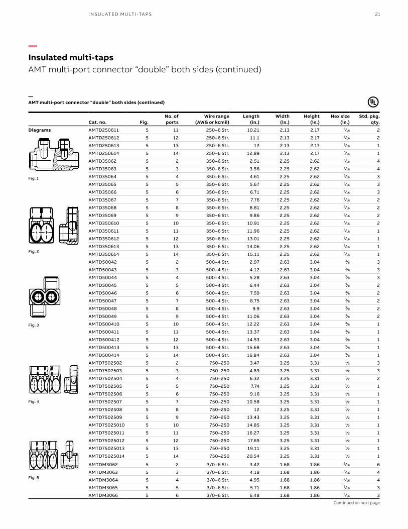
—AMT multi-port connector “double” both sides (continued)
Cat. no. Fig.No. ofports
Wire range (AWG or kcmil)
Length (in.)
Width (in.)
Height (in.)
Hex size (in.)
Std. pkg. qty.
Diagrams AMTD250611 5 11 250–6 Str. 10.21 2.13 2.17 5⁄16 2
AMTD250612 5 12 250–6 Str. 11.1 2.13 2.17 5⁄16 2
AMTD250613 5 13 250–6 Str. 12 2.13 2.17 5⁄16 1
AMTD250614 5 14 250–6 Str. 12.89 2.13 2.17 5⁄16 1
AMTD35062 5 2 350–6 Str. 2.51 2.25 2.62 5⁄16 4
AMTD35063 5 3 350–6 Str. 3.56 2.25 2.62 5⁄16 4
AMTD35064 5 4 350–6 Str. 4.61 2.25 2.62 5⁄16 3
AMTD35065 5 5 350–6 Str. 5.67 2.25 2.62 5⁄16 3
AMTD35066 5 6 350–6 Str. 6.71 2.25 2.62 5⁄16 3
AMTD35067 5 7 350–6 Str. 7.76 2.25 2.62 5⁄16 2
AMTD35068 5 8 350–6 Str. 8.81 2.25 2.62 5⁄16 2
AMTD35069 5 9 350–6 Str. 9.86 2.25 2.62 5⁄16 2
AMTD350610 5 10 350–6 Str. 10.91 2.25 2.62 5⁄16 2
AMTD350611 5 11 350–6 Str. 11.96 2.25 2.62 5⁄16 1
AMTD350612 5 12 350–6 Str. 13.01 2.25 2.62 5⁄16 1
AMTD350613 5 13 350–6 Str. 14.06 2.25 2.62 5⁄16 1
AMTD350614 5 14 350–6 Str. 15.11 2.25 2.62 5⁄16 1
AMTD50042 5 2 500–4 Str. 2.97 2.63 3.04 3⁄8 3
AMTD50043 5 3 500–4 Str. 4.12 2.63 3.04 3⁄8 3
AMTD50044 5 4 500–4 Str. 5.28 2.63 3.04 3⁄8 3
AMTD50045 5 5 500–4 Str. 6.44 2.63 3.04 3⁄8 2
AMTD50046 5 6 500–4 Str. 7.59 2.63 3.04 3⁄8 2
AMTD50047 5 7 500–4 Str. 8.75 2.63 3.04 3⁄8 2
AMTD50048 5 8 500–4 Str. 9.9 2.63 3.04 3⁄8 2
AMTD50049 5 9 500–4 Str. 11.06 2.63 3.04 3⁄8 2
AMTD500410 5 10 500–4 Str. 12.22 2.63 3.04 3⁄8 1
AMTD500411 5 11 500–4 Str. 13.37 2.63 3.04 3⁄8 1
AMTD500412 5 12 500–4 Str. 14.53 2.63 3.04 3⁄8 1
AMTD500413 5 13 500–4 Str. 15.68 2.63 3.04 3⁄8 1
AMTD500414 5 14 500–4 Str. 16.84 2.63 3.04 3⁄8 1
AMTD7502502 5 2 750–250 3.47 3.25 3.31 1⁄2 3
AMTD7502503 5 3 750–250 4.89 3.25 3.31 1⁄2 3
AMTD7502504 5 4 750–250 6.32 3.25 3.31 1⁄2 2
AMTD7502505 5 5 750–250 7.74 3.25 3.31 1⁄2 1
AMTD7502506 5 6 750–250 9.16 3.25 3.31 1⁄2 1
AMTD7502507 5 7 750–250 10.58 3.25 3.31 1⁄2 1
AMTD7502508 5 8 750–250 12 3.25 3.31 1⁄2 1
AMTD7502509 5 9 750–250 13.43 3.25 3.31 1⁄2 1
AMTD75025010 5 10 750–250 14.85 3.25 3.31 1⁄2 1
AMTD75025011 5 11 750–250 16.27 3.25 3.31 1⁄2 1
AMTD75025012 5 12 750–250 17.69 3.25 3.31 1⁄2 1
AMTD75025013 5 13 750–250 19.11 3.25 3.31 1⁄2 1
AMTD75025014 5 14 750–250 20.54 3.25 3.31 1⁄2 1
AMTDM3062 5 2 3/0–6 Str. 3.42 1.68 1.86 3⁄16 6
AMTDM3063 5 3 3/0–6 Str. 4.18 1.68 1.86 3⁄16 4
AMTDM3064 5 4 3/0–6 Str. 4.95 1.68 1.86 3⁄16 4
AMTDM3065 5 5 3/0–6 Str. 5.71 1.68 1.86 3⁄16 3
AMTDM3066 5 6 3/0–6 Str. 6.48 1.68 1.86 3⁄16 3Continued on next page
—Insulated multi-tapsAMT multi-port connector “double” both sides (continued)
Fig. 1
Fig. 3
Fig. 5
Fig. 2
Fig. 4
I NSU L ATED M U LTI -TA P S
22 B L ACK B U R N M ECH A N I C A L CO N N EC TO R S
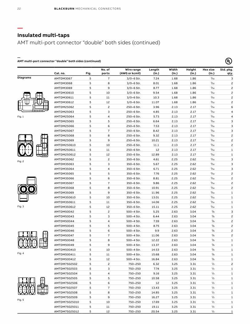
—AMT multi-port connector “double” both sides (continued)
Cat. no. Fig.No. ofports
Wire range (AWG or kcmil)
Length (in.)
Width (in.)
Height (in.)
Hex size (in.)
Std. pkg. qty.
Diagrams AMTDM3067 5 7 3/0–6 Str. 7.24 1.68 1.86 3⁄16 3
AMTDM3068 5 8 3/0–6 Str. 8.01 1.68 1.86 3⁄16 2
AMTDM3069 5 9 3/0–6 Str. 8.77 1.68 1.86 3⁄16 2
AMTDM30610 5 10 3/0–6 Str. 9.54 1.68 1.86 3⁄16 2
AMTDM30611 5 11 3/0–6 Str. 10.3 1.68 1.86 3⁄16 2
AMTDM30612 5 12 3/0–6 Str. 11.07 1.68 1.86 3⁄16 2
AMTDM25062 5 2 250–6 Str. 3.96 2.13 2.17 5⁄16 6
AMTDM25063 5 3 250–6 Str. 4.85 2.13 2.17 5⁄16 4
AMTDM25064 5 4 250–6 Str. 5.73 2.13 2.17 5⁄16 4
AMTDM25065 5 5 250–6 Str. 6.64 2.13 2.17 5⁄16 3
AMTDM25066 5 6 250–6 Str. 7.53 2.13 2.17 5⁄16 3
AMTDM25067 5 7 250–6 Str. 8.42 2.13 2.17 5⁄16 3
AMTDM25068 5 8 250–6 Str. 9.32 2.13 2.17 5⁄16 2
AMTDM25069 5 9 250–6 Str. 10.21 2.13 2.17 5⁄16 2
AMTDM250610 5 10 250–6 Str. 11.1 2.13 2.17 5⁄16 2
AMTDM250611 5 11 250–6 Str. 12 2.13 2.17 5⁄16 1
AMTDM250612 5 12 250–6 Str. 12.89 2.13 2.17 5⁄16 1
AMTDM35062 5 2 350–6 Str. 4.61 2.25 2.62 5⁄16 3
AMTDM35063 5 3 350–6 Str. 5.67 2.25 2.62 5⁄16 3
AMTDM35064 5 4 350–6 Str. 6.71 2.25 2.62 5⁄16 3
AMTDM35065 5 5 350–6 Str. 7.76 2.25 2.62 5⁄16 2
AMTDM35066 5 6 350–6 Str. 8.81 2.25 2.62 5⁄16 2
AMTDM35067 5 7 350–6 Str. 9.86 2.25 2.62 5⁄16 2
AMTDM35068 5 8 350–6 Str. 10.91 2.25 2.62 5⁄16 2
AMTDM35069 5 9 350–6 Str. 11.96 2.25 2.62 5⁄16 1
AMTDM350610 5 10 350–6 Str. 13.01 2.25 2.62 5⁄16 1
AMTDM350611 5 11 350–6 Str. 14.06 2.25 2.62 5⁄16 1
AMTDM350612 5 12 350–6 Str. 15.11 2.25 2.62 5⁄16 1
AMTDM50042 5 2 500–4 Str. 5.25 2.63 3.04 3⁄8 3
AMTDM50043 5 3 500–4 Str. 6.44 2.63 3.04 3⁄8 2
AMTDM50044 5 4 500–4 Str. 7.59 2.63 3.04 3⁄8 2
AMTDM50045 5 5 500–4 Str. 8.75 2.63 3.04 3⁄8 2
AMTDM50046 5 6 500–4 Str. 9.9 2.63 3.04 3⁄8 2
AMTDM50047 5 7 500–4 Str. 11.06 2.63 3.04 3⁄8 2
AMTDM50048 5 8 500–4 Str. 12.22 2.63 3.04 3⁄8 1
AMTDM50049 5 9 500–4 Str. 13.37 2.63 3.04 3⁄8 1
AMTDM500410 5 10 500–4 Str. 14.53 2.63 3.04 3⁄8 1
AMTDM500411 5 11 500–4 Str. 15.68 2.63 3.04 3⁄8 1
AMTDM500412 5 12 500–4 Str. 16.84 2.63 3.04 3⁄8 1
AMTDM7502502 5 2 750–250 6.32 3.25 3.31 1⁄2 2
AMTDM7502503 5 3 750–250 7.74 3.25 3.31 1⁄2 1
AMTDM7502504 5 4 750–250 9.16 3.25 3.31 1⁄2 1
AMTDM7502505 5 5 750–250 10.58 3.25 3.31 1⁄2 1
AMTDM7502506 5 6 750–250 12 3.25 3.31 1⁄2 1
AMTDM7502507 5 7 750–250 13.43 3.25 3.31 1⁄2 1
AMTDM7502508 5 8 750–250 14.85 3.25 3.31 1⁄2 1
AMTDM7502509 5 9 750–250 16.27 3.25 3.31 1⁄2 1
AMTDM75025010 5 10 750–250 17.69 3.25 3.31 1⁄2 1
AMTDM75025011 5 11 750–250 19.11 3.25 3.31 1⁄2 1
AMTDM75025012 5 12 750–250 20.54 3.25 3.31 1⁄2 1
—Insulated multi-tapsAMT multi-port connector “double” both sides (continued)
Fig. 1
Fig. 3
Fig. 5
Fig. 2
Fig. 4
23P OW ER D IS TR I B U TI O N B LO CK S
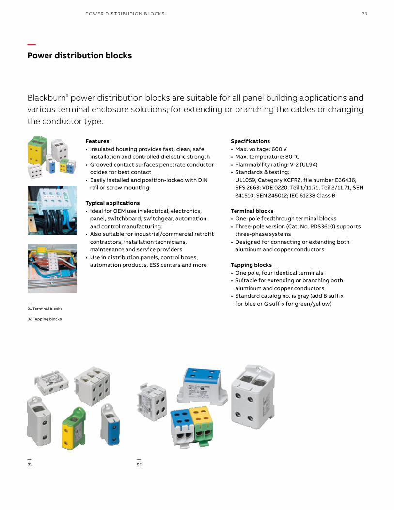
Features• Insulated housing provides fast, clean, safe
installation and controlled dielectric strength• Grooved contact surfaces penetrate conductor
oxides for best contact• Easily installed and position-locked with DIN
rail or screw mounting
Typical applications• Ideal for OEM use in electrical, electronics,
panel, switchboard, switchgear, automation and control manufacturing
• Also suitable for industrial/commercial retrofit contractors, installation technicians, maintenance and service providers
• Use in distribution panels, control boxes, automation products, ESS centers and more
—02
—01 Terminal blocks—02 Tapping blocks
—01
—Power distribution blocks
Specifications• Max. voltage: 600 V• Max. temperature: 80 °C• Flammability rating: V-2 (UL94)• Standards & testing:
UL1059, Category XCFR2, file number E66436; SFS 2663; VDE 0220, Teil 1/11.71, Teil 2/11.71, SEN 241510, SEN 245012; IEC 61238 Class B
Terminal blocks• One-pole feedthrough terminal blocks• Three-pole version (Cat. No. PDS3610) supports
three-phase systems• Designed for connecting or extending both
aluminum and copper conductors
Tapping blocks• One pole, four identical terminals• Suitable for extending or branching both
aluminum and copper conductors• Standard catalog no. is gray (add B suffix
for blue or G suffix for green/yellow)
Blackburn® power distribution blocks are suitable for all panel building applications and various terminal enclosure solutions; for extending or branching the cables or changing the conductor type.
24 B L ACK B U R N M ECH A N I C A L CO N N EC TO R S
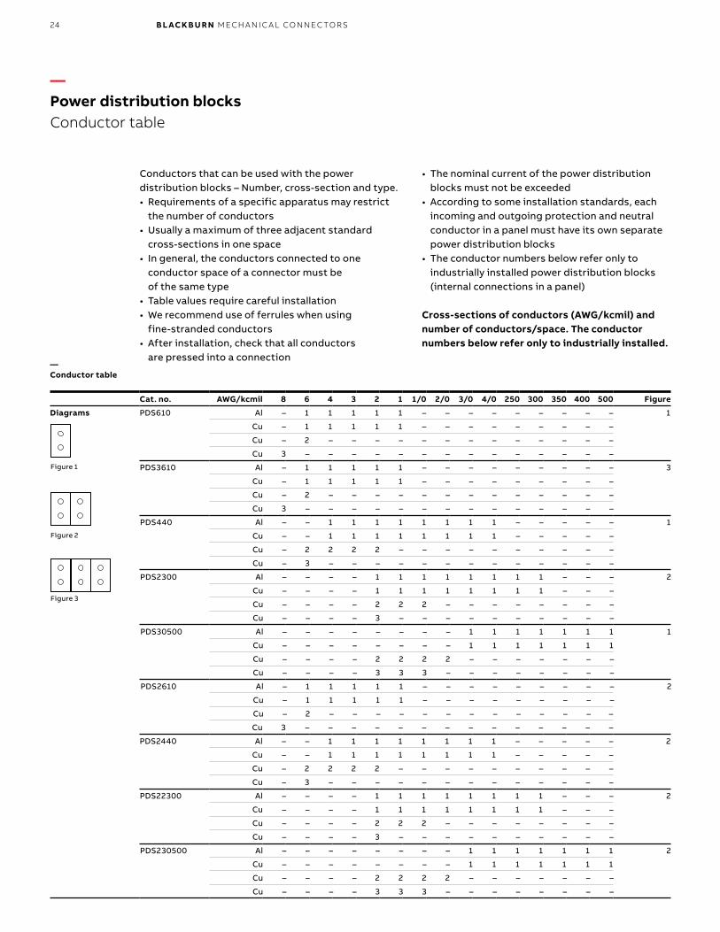
Conductors that can be used with the power distribution blocks – Number, cross-section and type.• Requirements of a specific apparatus may restrict
the number of conductors• Usually a maximum of three adjacent standard
cross-sections in one space• In general, the conductors connected to one
conductor space of a connector must be of the same type
• Table values require careful installation• We recommend use of ferrules when using
fine-stranded conductors• After installation, check that all conductors
are pressed into a connection—Conductor table
Cat. no. AWG/kcmil 8 6 4 3 2 1 1/0 2/0 3/0 4/0 250 300 350 400 500 Figure
Diagrams PDS610 Al – 1 1 1 1 1 – – – – – – – – – 1
Cu – 1 1 1 1 1 – – – – – – – – –
Cu – 2 – – – – – – – – – – – – –
Cu 3 – – – – – – – – – – – – – –
PDS3610 Al – 1 1 1 1 1 – – – – – – – – – 3
Cu – 1 1 1 1 1 – – – – – – – – –
Cu – 2 – – – – – – – – – – – – –
Cu 3 – – – – – – – – – – – – – –
PDS440 Al – – 1 1 1 1 1 1 1 1 – – – – – 1
Cu – – 1 1 1 1 1 1 1 1 – – – – –
Cu – 2 2 2 2 – – – – – – – – – –
Cu – 3 – – – – – – – – – – – – –
PDS2300 Al – – – – 1 1 1 1 1 1 1 1 – – – 2
Cu – – – – 1 1 1 1 1 1 1 1 – – –
Cu – – – – 2 2 2 – – – – – – – –
Cu – – – – 3 – – – – – – – – – –
PDS30500 Al – – – – – – – – 1 1 1 1 1 1 1 1
Cu – – – – – – – – 1 1 1 1 1 1 1
Cu – – – – 2 2 2 2 – – – – – – –
Cu – – – – 3 3 3 – – – – – – – –
PDS2610 Al – 1 1 1 1 1 – – – – – – – – – 2
Cu – 1 1 1 1 1 – – – – – – – – –
Cu – 2 – – – – – – – – – – – – –
Cu 3 – – – – – – – – – – – – – –
PDS2440 Al – – 1 1 1 1 1 1 1 1 – – – – – 2
Cu – – 1 1 1 1 1 1 1 1 – – – – –
Cu – 2 2 2 2 – – – – – – – – – –
Cu – 3 – – – – – – – – – – – – –
PDS22300 Al – – – – 1 1 1 1 1 1 1 1 – – – 2
Cu – – – – 1 1 1 1 1 1 1 1 – – –
Cu – – – – 2 2 2 – – – – – – – –
Cu – – – – 3 – – – – – – – – – –
PDS230500 Al – – – – – – – – 1 1 1 1 1 1 1 2
Cu – – – – – – – – 1 1 1 1 1 1 1
Cu – – – – 2 2 2 2 – – – – – – –
Cu – – – – 3 3 3 – – – – – – – –
Figure 1
Figure 2
Figure 3
—Power distribution blocksConductor table
• The nominal current of the power distribution blocks must not be exceeded
• According to some installation standards, each incoming and outgoing protection and neutral conductor in a panel must have its own separate power distribution blocks
• The conductor numbers below refer only to industrially installed power distribution blocks (internal connections in a panel)
Cross-sections of conductors (AWG/kcmil) and number of conductors/space. The conductor numbers below refer only to industrially installed.
25
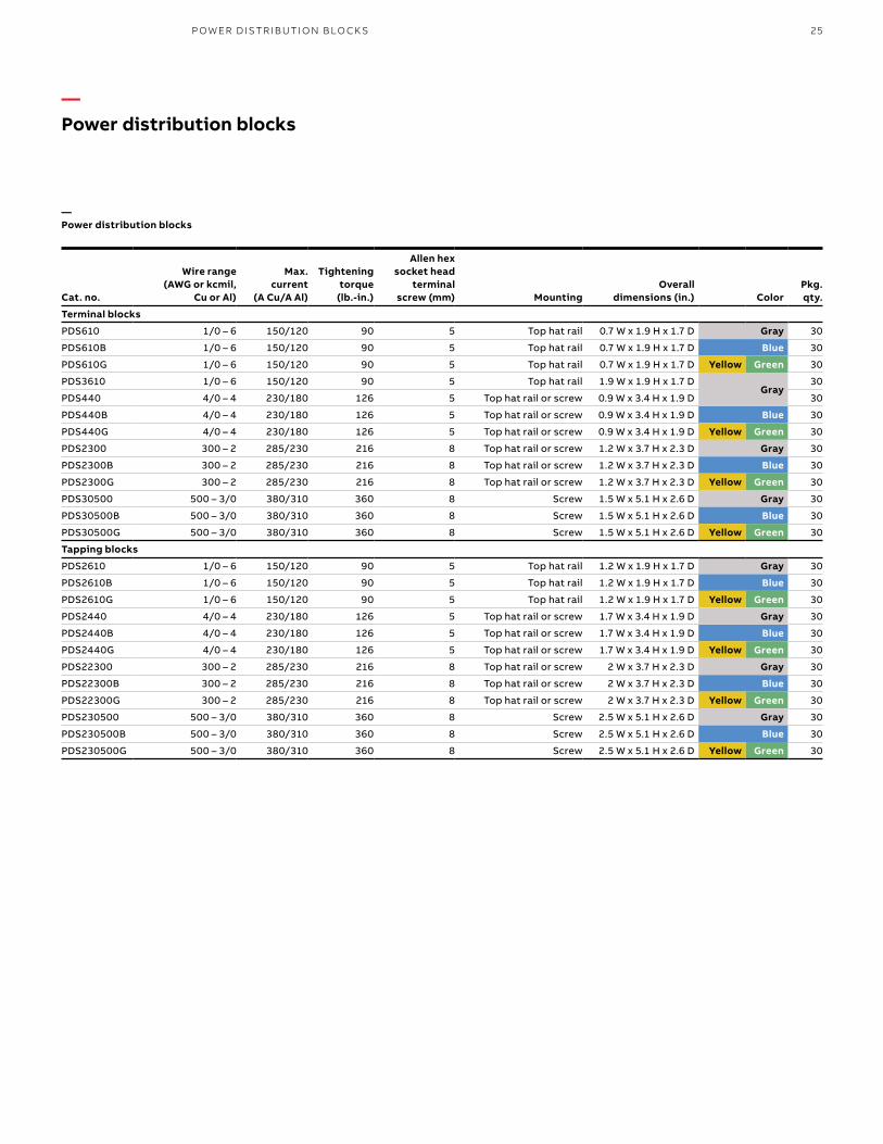
Cat. no.
Wire range (AWG or kcmil,
Cu or Al)
Max.current
(A Cu/A Al)
Tighteningtorque
(lb.-in.)
Allen hex socket head
terminal screw (mm) Mounting
Overalldimensions (in.) Color
Pkg.qty.
Terminal blocks
PDS610 1/0 – 6 150/120 90 5 Top hat rail 0.7 W x 1.9 H x 1.7 D Gray 30
PDS610B 1/0 – 6 150/120 90 5 Top hat rail 0.7 W x 1.9 H x 1.7 D Blue 30
PDS610G 1/0 – 6 150/120 90 5 Top hat rail 0.7 W x 1.9 H x 1.7 D Yellow Green 30
PDS3610 1/0 – 6 150/120 90 5 Top hat rail 1.9 W x 1.9 H x 1.7 DGray
30
PDS440 4/0 – 4 230/180 126 5 Top hat rail or screw 0.9 W x 3.4 H x 1.9 D 30
PDS440B 4/0 – 4 230/180 126 5 Top hat rail or screw 0.9 W x 3.4 H x 1.9 D Blue 30
PDS440G 4/0 – 4 230/180 126 5 Top hat rail or screw 0.9 W x 3.4 H x 1.9 D Yellow Green 30
PDS2300 300 – 2 285/230 216 8 Top hat rail or screw 1.2 W x 3.7 H x 2.3 D Gray 30
PDS2300B 300 – 2 285/230 216 8 Top hat rail or screw 1.2 W x 3.7 H x 2.3 D Blue 30
PDS2300G 300 – 2 285/230 216 8 Top hat rail or screw 1.2 W x 3.7 H x 2.3 D Yellow Green 30
PDS30500 500 – 3/0 380/310 360 8 Screw 1.5 W x 5.1 H x 2.6 D Gray 30
PDS30500B 500 – 3/0 380/310 360 8 Screw 1.5 W x 5.1 H x 2.6 D Blue 30
PDS30500G 500 – 3/0 380/310 360 8 Screw 1.5 W x 5.1 H x 2.6 D Yellow Green 30
Tapping blocks
PDS2610 1/0 – 6 150/120 90 5 Top hat rail 1.2 W x 1.9 H x 1.7 D Gray 30
PDS2610B 1/0 – 6 150/120 90 5 Top hat rail 1.2 W x 1.9 H x 1.7 D Blue 30
PDS2610G 1/0 – 6 150/120 90 5 Top hat rail 1.2 W x 1.9 H x 1.7 D Yellow Green 30
PDS2440 4/0 – 4 230/180 126 5 Top hat rail or screw 1.7 W x 3.4 H x 1.9 D Gray 30
PDS2440B 4/0 – 4 230/180 126 5 Top hat rail or screw 1.7 W x 3.4 H x 1.9 D Blue 30
PDS2440G 4/0 – 4 230/180 126 5 Top hat rail or screw 1.7 W x 3.4 H x 1.9 D Yellow Green 30
PDS22300 300 – 2 285/230 216 8 Top hat rail or screw 2 W x 3.7 H x 2.3 D Gray 30
PDS22300B 300 – 2 285/230 216 8 Top hat rail or screw 2 W x 3.7 H x 2.3 D Blue 30
PDS22300G 300 – 2 285/230 216 8 Top hat rail or screw 2 W x 3.7 H x 2.3 D Yellow Green 30
PDS230500 500 – 3/0 380/310 360 8 Screw 2.5 W x 5.1 H x 2.6 D Gray 30
PDS230500B 500 – 3/0 380/310 360 8 Screw 2.5 W x 5.1 H x 2.6 D Blue 30
PDS230500G 500 – 3/0 380/310 360 8 Screw 2.5 W x 5.1 H x 2.6 D Yellow Green 30
—Power distribution blocks
—Power distribution blocks
P OW ER D IS TR I B U TI O N B LO CK S
26 B L ACK B U R N M ECH A N I C A L CO N N EC TO R S
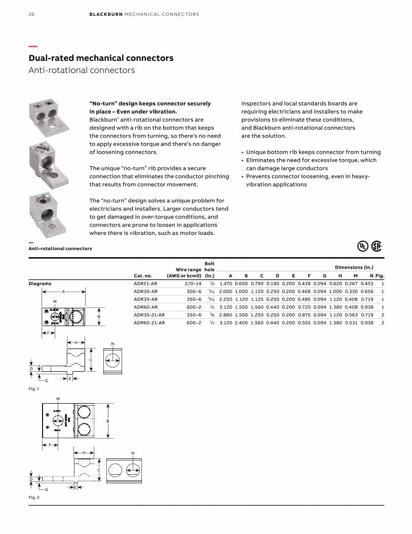
Cat. no.Wire range
(AWG or kcmil)
Bolt hole (in.)
Dimensions (in.)
Fig. A B C D E F G H M N
Diagrams ADR21-AR 2/0–14 1⁄4 1.470 0.600 0.790 0.190 0.200 0.438 0.094 0.620 0.267 0.453 1
ADR30-AR 300–6 7⁄16 2.000 1.000 1.120 0.250 0.200 0.468 0.094 1.000 0.330 0.656 1
ADR35-AR 350–6 5⁄16 2.250 1.120 1.125 0.250 0.200 0.485 0.094 1.120 0.408 0.719 1
ADR60-AR 600–2 1⁄2 3.120 1.500 1.560 0.440 0.200 0.720 0.094 1.380 0.408 0.938 1
ADR35-21-AR 350–6 3⁄8 2.880 1.500 1.250 0.250 0.200 0.875 0.094 1.120 0.563 0.719 2
ADR60-21-AR 600–2 1⁄2 3.120 2.400 1.560 0.440 0.200 0.555 0.094 1.380 0.531 0.938 2
Fig. 1
Fig. 2
“No-turn” design keeps connector securely in place – Even under vibration. Blackburn® anti-rotational connectors are designed with a rib on the bottom that keeps the connectors from turning, so there’s no need to apply excessive torque and there’s no danger of loosening connectors.
The unique “no-turn” rib provides a secure connection that eliminates the conductor pinching that results from connector movement.
The “no-turn” design solves a unique problem for electricians and installers. Larger conductors tend to get damaged in over-torque conditions, and connectors are prone to loosen in applications where there is vibration, such as motor loads.
G E
D
A
M
N
B
F
H
C
G E
D
M
N
B
F
H
C
—Dual-rated mechanical connectorsAnti-rotational connectors
Inspectors and local standards boards are requiring electricians and installers to make provisions to eliminate these conditions, and Blackburn anti-rotational connectors are the solution.
• Unique bottom rib keeps connector from turning • Eliminates the need for excessive torque, which
can damage large conductors• Prevents connector loosening, even in heavy-
vibration applications
—Anti-rotational connectors
27D UA L- R ATED M ECH A N I C A L CO N N EC TO R S
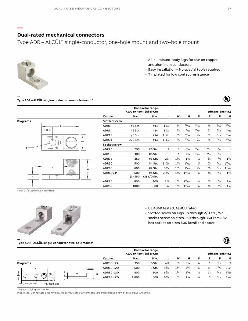
Cat. no.
Conductor range AWG or kcmil (Al or Cu) Dimensions (in.)
Max. Min. L W H D E F G
Diagrams Slotted screw
ADR6 #6 Str. #14 13⁄64 1⁄2 31⁄64 15⁄64 1⁄4 5⁄64 43⁄64
ADR2 #2 Str. #14 15⁄32 1⁄2 9⁄16 19⁄64 1⁄4 7⁄64 11⁄16
ADR11 1/0 Str. #14 115⁄32 5⁄8 25⁄32 7⁄16 1⁄4 3⁄16 27⁄32
ADR21 2/0 Str. #14 115⁄32 5⁄8 25⁄32 7⁄16 1⁄4 3⁄16 27⁄32
Socket screw
ADR25 250 #6 Str. 2 1 11⁄8 15⁄32 5⁄16 1⁄4 1
ADR30 300 #6 Str. 2 1 11⁄8 15⁄32 5⁄16 1⁄4 1
ADR35 350 #6 Str. 21⁄4 11⁄8 11⁄4 1⁄2 3⁄8 1⁄4 11⁄8
ADR50 500 #4 Str. 213⁄16 11⁄2 19⁄16 3⁄4 3⁄8 5⁄16 119⁄32
ADR60 600 #2 Str. 33⁄16 11⁄2 19⁄16 13⁄16 3⁄8 7⁄16 113⁄16
ADR6004* 600 (2) 250
#4 Str. (2) 1/0 Str.
213⁄16 13⁄8 113⁄16 5⁄8 3⁄8 5⁄16 11⁄2
ADR80 800 300 33⁄8 13⁄4 115⁄16 5⁄8 5⁄8 1⁄2 13⁄4
ADR99 1000 500 33⁄8 13⁄4 115⁄16 5⁄8 5⁄8 1⁄2 13⁄4
* Not UL® listed or CSA certified.
• All-aluminum-body lugs for use on copper and aluminum conductors
• Easy installation – No special tools required• Tin plated for low contact resistance
Cat. no.
Conductor range AWG or kcmil (Al or Cu) Dimensions (in.)
Max. Min. L W H D E F G
Diagrams ADR35-12# 350 6 Str. 41⁄4 11⁄4 13⁄8 5⁄8 1⁄2 5⁄16 3
ADR60-12D 600 2 Str. 55⁄16 11⁄2 11⁄2 5⁄8 1⁄2 3⁄8 31⁄16
ADR80-12D 800 300 63⁄16 13⁄4 17⁄8 5⁄8 1⁄2 9⁄16 37⁄16
ADR99-12D 1,000 500 63⁄16 13⁄4 17⁄8 5⁄8 1⁄2 9⁄16 37⁄16
* NEMA spacing: 13⁄4" centers# UL listed. Connectors accommodating conductors 600 kcmil and larger have double row of set screws (D suffix).
G HF
“E” bolt size
L
W
D 13⁄4
L
D
E
F
D
W
H
—Dual-rated mechanical connectorsType ADR – ALCÜL™ single-conductor, one-hole mount and two-hole mount
—Type ADR – ALCÜL single-conductor, two-hole mount*
—Type ADR – ALCÜL single-conductor, one-hole mount*
• UL 486B tested, AL9CU rated• Slotted screw on lugs up through 2/0 str.; 5⁄16"
socket screw on sizes 250 through 350 kcmil; 3⁄8" hex socket on sizes 500 kcmil and above
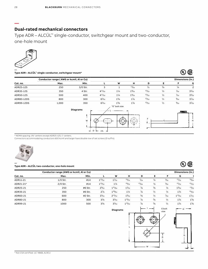
28 B L ACK B U R N M ECH A N I C A L CO N N EC TO R S
Cat. no.
Conductor range ( AWG or kcmil, Al or Cu) Dimensions (in.)
Max. Min. L W H D E F G
ADR25-12S 250 3/0 Str. 3 1 13⁄16 1⁄2 3⁄8 1⁄4 2
ADR35-12S 350 4 Str. 411⁄16 11⁄4 19⁄16 23⁄32 1⁄2 7⁄16 35⁄16
ADR50-12S 500 400 411⁄16 11⁄4 19⁄16 23⁄32 1⁄2 7⁄16 35⁄16
ADR80-12DS 800 300 63⁄16 15⁄8 17⁄8 23⁄32 1⁄2 9⁄16 37⁄16
ADR99-12DS 1,000 350 63⁄16 15⁄8 17⁄8 23⁄32 1⁄2 9⁄16 37⁄16
* NEMA spacing: 13⁄4" centers except ADR25-12S: 1" centers.Connectors accommodating conductors 600 kcmil and larger have double row of set screws (D suffix).
Cat. no.
Conductor range (AWG or kcmil, Al or Cu) Dimensions (in.)
Max. Min. L W H D E F G I
ADR11-21 1/0 Str. #14 115⁄32 17⁄32 25⁄32 7⁄16 1⁄4 3⁄16 27⁄32 35⁄64
ADR21-21* 2/0 Str. #14 115⁄32 11⁄4 25⁄32 27⁄64 1⁄4 3⁄16 27⁄32 21⁄32
ADR25-21 250 #6 Str. 29⁄16 141⁄64 13⁄16 7⁄8 3⁄8 1⁄4 19⁄16 13⁄16
ADR35-21 350 #6 Str. 27⁄8 159⁄64 11⁄4 7⁄8 1⁄2 1⁄4 13⁄4 61⁄64
ADR60-21 600 #2 Str. 33⁄16 213⁄32 19⁄16 5⁄8 1⁄2 7⁄16 113⁄16 17⁄32
ADR80-21 800 300 33⁄8 33⁄16 115⁄16 7⁄8 5⁄8 1⁄2 13⁄4 15⁄8
ADR99-21 1000 500 33⁄8 33⁄16 115⁄16 7⁄8 5⁄8 1⁄2 13⁄4 15⁄8
* Not CSA certified. U L® 486B, AL9CU
“E” bolt size
G HF
L
W
D 13⁄4
L
E bolt size
D
W
I
G
H
F
—Dual-rated mechanical connectorsType ADR – ALCÜL™ single-conductor, switchgear mount and two-conductor, one-hole mount
—Type ADR – ALCÜL™ single-conductor, switchgear mount*
—Type ADR – ALCÜL two-conductor, one-hole mount
Diagrams
Diagrams
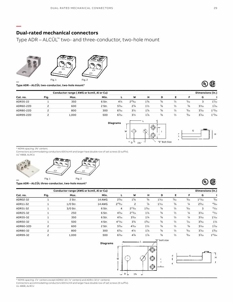
29D UA L- R ATED M ECH A N I C A L CO N N EC TO R S
Cat. no. Fig.
Conductor range ( AWG or kcmil, Al or Cu) Dimensions (in.)
Max. Min. L W H D E F G I
ADR35-22 1 350 6 Str. 41⁄4 219⁄64 13⁄8 5⁄8 1⁄2 5⁄16 3 17⁄32
ADR60-22D 2 600 2 Str. 55⁄16 23⁄4 11⁄2 5⁄8 1⁄2 3⁄8 31⁄16 17⁄16
ADR80-22D 2 800 300 63⁄16 31⁄2 17⁄8 5⁄8 1⁄2 9⁄16 37⁄16 113⁄16
ADR99-22D 2 1,000 500 63⁄16 31⁄2 17⁄8 5⁄8 1⁄2 9⁄16 37⁄16 113⁄16
* NEMA spacing: 13⁄4" centers.Connectors accommodating conductors 600 kcmil and larger have double row of set screws (D suffix).UL® 486B, AL9CU
Cat. no. Fig.
Conductor range (AWG or kcmil, Al or Cu) Dimensions (in.)
Max. Min. L W H D E F G I
ADR02-32 1 2 Str. 14 AWG 23⁄16 15⁄8 5⁄8 11⁄32 5⁄16 3⁄16 111⁄16 9⁄16
ADR11-32 1 1/0 Str. 14 AWG 229⁄32 2 7⁄8 11⁄32 3⁄8 1⁄4 25⁄32 45⁄64
ADR31-32 1 3/0 Str. 6 Str. 4 213⁄16 13⁄16 5⁄8 1⁄2 5⁄16 3 31⁄32
ADR25-32 1 250 6 Str. 43⁄16 213⁄16 11⁄4 5⁄8 1⁄2 1⁄4 31⁄16 31⁄32
ADR35-32 1 350 6 Str. 43⁄16 33⁄16 11⁄4 5⁄8 1⁄2 1⁄4 31⁄16 11⁄32
ADR50-32 1 500 4 Str. 411⁄16 33⁄4 19⁄16 5⁄8 1⁄2 7⁄16 35⁄16 11⁄4
ADR60-32D 2 600 2 Str. 55⁄16 43⁄16 11⁄2 5⁄8 1⁄2 3⁄8 31⁄16 17⁄16
ADR80-32 2 800 300 63⁄16 41⁄2 17⁄8 5⁄8 1⁄2 9⁄16 37⁄16 19⁄16
ADR99-32 2 1,000 500 63⁄16 43⁄4 17⁄8 5⁄8 1⁄2 9⁄16 37⁄16 141⁄64
* NEMA spacing: 13⁄4" centers except ADR02-32 ( 7⁄8" centers) and ADR11-32 (1" centers).Connectors accommodating conductors 600 kcmil and larger have double row of set screws (D suffix).UL 486B, AL9CU
F GH
13⁄4D
WI
L “E” bolt size
Fig. 2Fig. 1
L
I
D
W G
H
“E” Bolt Size13⁄4"
—Dual-rated mechanical connectorsType ADR – ALCÜL™ two- and three-conductor, two-hole mount
—Type ADR – ALCÜL three-conductor, two-hole mount*
—Type ADR – ALCÜL two-conductor, two-hole mount*
Diagrams
Diagrams
Fig. 2Fig. 1
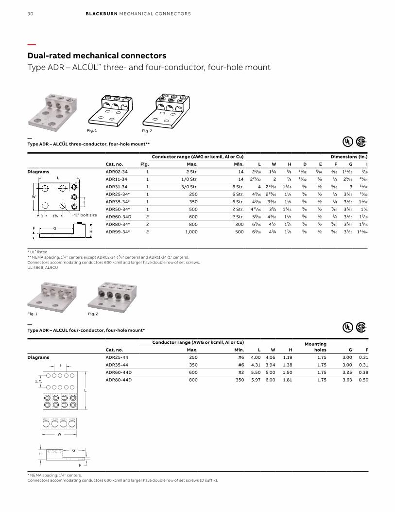
30 B L ACK B U R N M ECH A N I C A L CO N N EC TO R S
Cat. no. Fig.
Conductor range (AWG or kcmil, Al or Cu) Dimensions (in.)
Max. Min. L W H D E F G I
Diagrams ADR02-34 1 2 Str. 14 23⁄16 15⁄8 5⁄8 11⁄32 5⁄16 3⁄16 111⁄16 9⁄16
ADR11-34 1 1/0 Str. 14 229⁄32 2 7⁄8 11⁄32 3⁄8 1⁄4 25⁄32 45⁄64
ADR31-34 1 3/0 Str. 6 Str. 4 213⁄16 13⁄16 5⁄8 1⁄2 5⁄16 3 31⁄32
ADR25-34* 1 250 6 Str. 43⁄16 213⁄16 11⁄4 5⁄8 1⁄2 1⁄4 31⁄16 31⁄32
ADR35-34* 1 350 6 Str. 43⁄16 33⁄16 11⁄4 5⁄8 1⁄2 1⁄4 31⁄16 11⁄32
ADR50-34* 1 500 2 Str. 411⁄16 33⁄4 19⁄16 5⁄8 1⁄2 7⁄16 35⁄16 11⁄4
ADR60-34D 2 600 2 Str. 55⁄16 43⁄16 11⁄2 5⁄8 1⁄2 3⁄8 31⁄16 17⁄16
ADR80-34* 2 800 300 63⁄16 41⁄2 17⁄8 5⁄8 1⁄2 9⁄16 37⁄16 19⁄16
ADR99-34* 2 1,000 500 63⁄16 43⁄4 17⁄8 5⁄8 1⁄2 9⁄16 37⁄16 141⁄64
* UL® listed.** NEMA spacing: 13⁄4" centers except ADR02-34 ( 7⁄8" centers) and ADR11-34 (1" centers).Connectors accommodating conductors 600 kcmil and larger have double row of set screws.UL 486B, AL9CU
Cat. no.
Conductor range (AWG or kcmil, Al or Cu)
L W HMounting
holes G FMax. Min.
Diagrams ADR25-44 250 #6 4.00 4.06 1.19 1.75 3.00 0.31
ADR35-44 350 #6 4.31 3.94 1.38 1.75 3.00 0.31
ADR60-44D 600 #2 5.50 5.00 1.50 1.75 3.25 0.38
ADR80-44D 800 350 5.97 6.00 1.81 1.75 3.63 0.50
* NEMA spacing: 13⁄4" centers.Connectors accommodating conductors 600 kcmil and larger have double row of set screws (D suffix).
Fig. 1 Fig. 2
I
L
1.75
HG
F
W
Fig. 1 Fig. 2
GFH
13⁄4 “E” bolt sizeD
WI
L
—Dual-rated mechanical connectorsType ADR – ALCÜL™ three- and four-conductor, four-hole mount
—Type ADR – ALCÜL four-conductor, four-hole mount*
—Type ADR – ALCÜL three-conductor, four-hole mount**
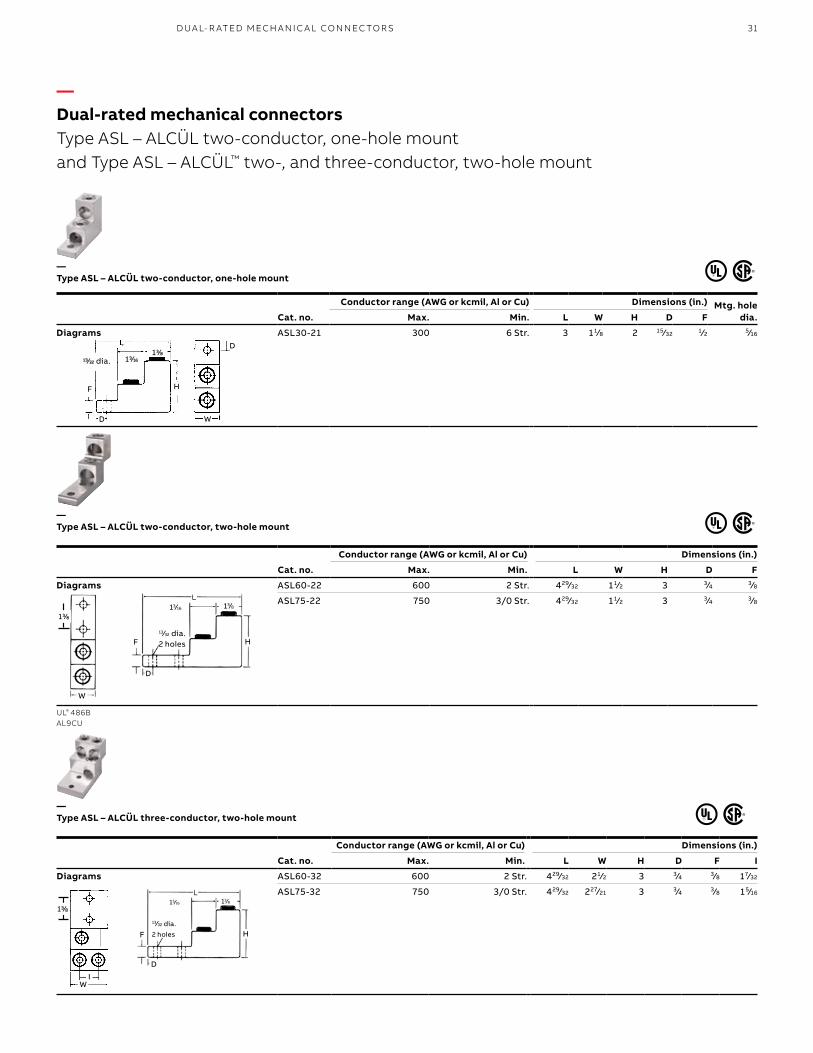
31D UA L- R ATED M ECH A N I C A L CO N N EC TO R S
13⁄32 dia. 13⁄1613⁄8
HF
D W
D
Cat. no.
Conductor range (AWG or kcmil, Al or Cu) Dimensions (in.) Mtg. hole dia.Max. Min. L W H D F
Diagrams ASL30-21 300 6 Str. 3 11⁄8 2 15⁄32 1⁄2 5⁄16
—Type ASL – ALCÜL two-conductor, one-hole mount
—Type ASL – ALCÜL two-conductor, two-hole mount
Cat. no.
Conductor range (AWG or kcmil, Al or Cu) Dimensions (in.)
Max. Min. L W H D F
Diagrams ASL60-22 600 2 Str. 429⁄32 11⁄2 3 3⁄4 3⁄8
ASL75-22 750 3/0 Str. 429⁄32 11⁄2 3 3⁄4 3⁄8
UL® 486BAL9CU
—Type ASL – ALCÜL three-conductor, two-hole mount
Cat. no.
Conductor range (AWG or kcmil, Al or Cu) Dimensions (in.)
Max. Min. L W H D F I
Diagrams ASL60-32 600 2 Str. 429⁄32 21⁄2 3 3⁄4 3⁄8 17⁄32
ASL75-32 750 3/0 Str. 429⁄32 227⁄21 3 3⁄4 3⁄8 15⁄16
13⁄32 dia.2 holes
13⁄16 13⁄813⁄8
W
HF
D
13⁄16 13⁄8
13⁄32 dia.
2 holes
13⁄8
H
IW
F
D
—Dual-rated mechanical connectorsType ASL – ALCÜL two-conductor, one-hole mount and Type ASL – ALCÜL™ two-, and three-conductor, two-hole mount
32 B L ACK B U R N M ECH A N I C A L CO N N EC TO R S
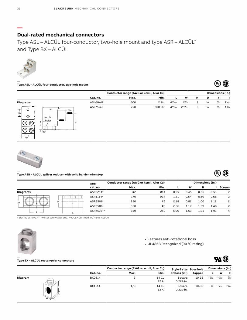
• Features anti-rotational boss• UL486B Recognized (90 °C rating)
Cat. no.
Conductor range (AWG or kcmil, Al or Cu) Style & size of boss (in.)
Boss hole tapped
Dimensions (in.)
Max. Min. L W H
Diagram BX0214 2 14 Cu 12 Al
Square 0.229 in.
10-32 15⁄32 15⁄32 9⁄16
BX1114 1/0 14 Cu12 Al
Square 0.229 in.
10-32 5⁄8 17⁄32 39⁄64
W
L
H
I
ABB cat. no.
Conductor range (AWG or kcmil, Al or Cu) Dimensions (In.)
ScrewsMax. Min. L W H I
Diagrams ASR0214* #2 #14 0.95 0.45 0.56 0.53 2
ASR1114* 1/0 #14 1.31 0.54 0.60 0.68 2
ASR2506 250 #6 2.18 0.81 1.00 1.12 2
ASR3506 350 #6 2.56 1.12 1.29 1.48 2
ASR7525** 750 250 6.00 1.53 1.95 1.93 4
* Slotted screws. ** Two set screws per end. Not CSA certified. UL® 486B AL9CU
H
LW
—Dual-rated mechanical connectorsType ASL – ALCÜL four-conductor, two-hole mount and type ASR – ALCÜL™ and Type BX – ALCÜL
—Type BX – ALCÜL rectangular connectors
—Type ASR – ALCÜL splicer reducer with solid barrier wire stop
—Type ASL – ALCÜL four-conductor, two-hole mount
Cat. no.
Conductor range (AWG or kcmil, Al or Cu) Dimensions (in.)
Max. Min. L W H D F I
Diagrams ASL60-42 600 2 Str. 429⁄32 21⁄2 3 3⁄4 3⁄8 17⁄32
ASL75-42 750 3/0 Str. 429⁄32 227⁄21 3 3⁄4 3⁄8 15⁄16
13⁄32 dia.2 holes
13⁄16 13⁄813⁄8
IW
HF
D
33D UA L- R ATED M ECH A N I C A L CO N N EC TO R S
ABB cat. no.
Conductor range (AWG or kcmil, Al or Cu) Dimensions (In.)
ScrewsMax. Min. L W H I
Diagrams ASR0214* #2 #14 0.95 0.45 0.56 0.53 2
ASR1114* 1/0 #14 1.31 0.54 0.60 0.68 2
ASR2506 250 #6 2.18 0.81 1.00 1.12 2
ASR3506 350 #6 2.56 1.12 1.29 1.48 2
ASR7525** 750 250 6.00 1.53 1.95 1.93 4
* Slotted screws. ** Two set screws per end. Not CSA certified. UL® 486B AL9CU
Cat. no.
Conductor range (AWG or kcmil, Al or Cu) Dimensions (in.)
Main Tap W L H
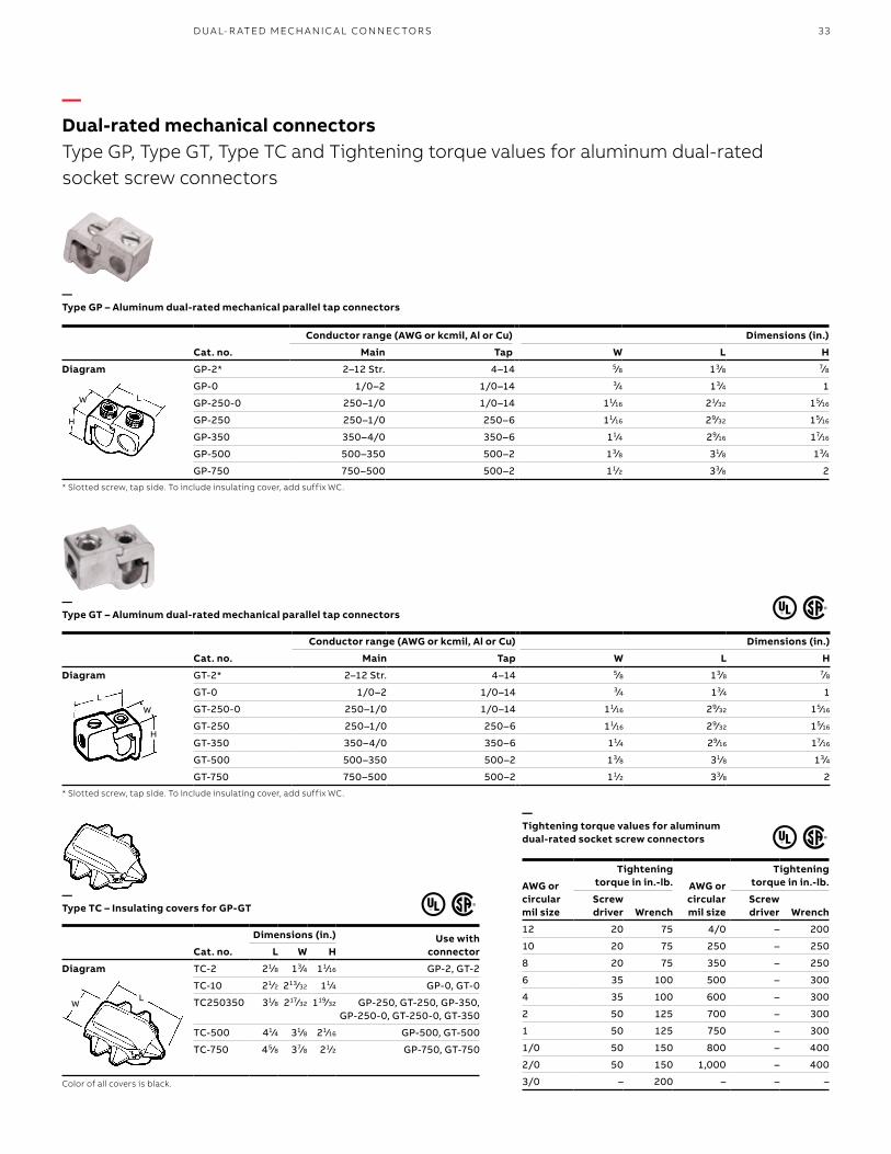
Diagram GP-2* 2–12 Str. 4–14 5⁄8 13⁄8 7⁄8
GP-0 1/0–2 1/0–14 3⁄4 13⁄4 1
GP-250-0 250–1/0 1/0–14 11⁄16 21⁄32 15⁄16
GP-250 250–1/0 250–6 11⁄16 29⁄32 15⁄16
GP-350 350–4/0 350–6 11⁄4 29⁄16 17⁄16
GP-500 500–350 500–2 13⁄8 31⁄8 13⁄4
GP-750 750–500 500–2 11⁄2 33⁄8 2
* Slotted screw, tap side. To include insulating cover, add suffix WC.
H
W L
—Type GP – Aluminum dual-rated mechanical parallel tap connectors
Cat. no.
Conductor range (AWG or kcmil, Al or Cu) Dimensions (in.)
Main Tap W L H
Diagram GT-2* 2–12 Str. 4–14 5⁄8 13⁄8 7⁄8
GT-0 1/0–2 1/0–14 3⁄4 13⁄4 1
GT-250-0 250–1/0 1/0–14 11⁄16 29⁄32 15⁄16
GT-250 250–1/0 250–6 11⁄16 29⁄32 15⁄16
GT-350 350–4/0 350–6 11⁄4 29⁄16 17⁄16
GT-500 500–350 500–2 13⁄8 31⁄8 13⁄4
GT-750 750–500 500–2 11⁄2 33⁄8 2
* Slotted screw, tap side. To include insulating cover, add suffix WC.
—Tightening torque values for aluminum dual-rated socket screw connectors
AWG or circular mil size
Tightening torque in in.-lb. AWG or
circular mil size
Tightening torque in in.-lb.
Screw driver Wrench
Screw driver Wrench
12 20 75 4/0 – 200
10 20 75 250 – 250
8 20 75 350 – 250
6 35 100 500 – 300
4 35 100 600 – 300
2 50 125 700 – 300
1 50 125 750 – 300
1/0 50 150 800 – 400
2/0 50 150 1,000 – 400
3/0 – 200 – – –
Cat. no.
Dimensions (in.) Use with connectorL W H
Diagram TC-2 21⁄8 13⁄4 11⁄16 GP-2, GT-2
TC-10 21⁄2 213⁄32 11⁄4 GP-0, GT-0
TC250350 31⁄8 217⁄32 119⁄32 GP-250, GT-250, GP-350,GP-250-0, GT-250-0, GT-350
TC-500 41⁄4 31⁄8 21⁄16 GP-500, GT-500
TC-750 45⁄8 37⁄8 21⁄2 GP-750, GT-750
Color of all covers is black.
LW
—Dual-rated mechanical connectorsType GP, Type GT, Type TC and Tightening torque values for aluminum dual-rated socket screw connectors
LW
H
—Type GT – Aluminum dual-rated mechanical parallel tap connectors
—Type TC – Insulating covers for GP-GT
—Type ASL – ALCÜL four-conductor, two-hole mount
Cat. no.
Conductor range (AWG or kcmil, Al or Cu) Dimensions (in.)
Max. Min. L W H D F I
Diagrams ASL60-42 600 2 Str. 429⁄32 21⁄2 3 3⁄4 3⁄8 17⁄32
ASL75-42 750 3/0 Str. 429⁄32 227⁄21 3 3⁄4 3⁄8 15⁄16
34 B L ACK B U R N M ECH A N I C A L CO N N EC TO R S
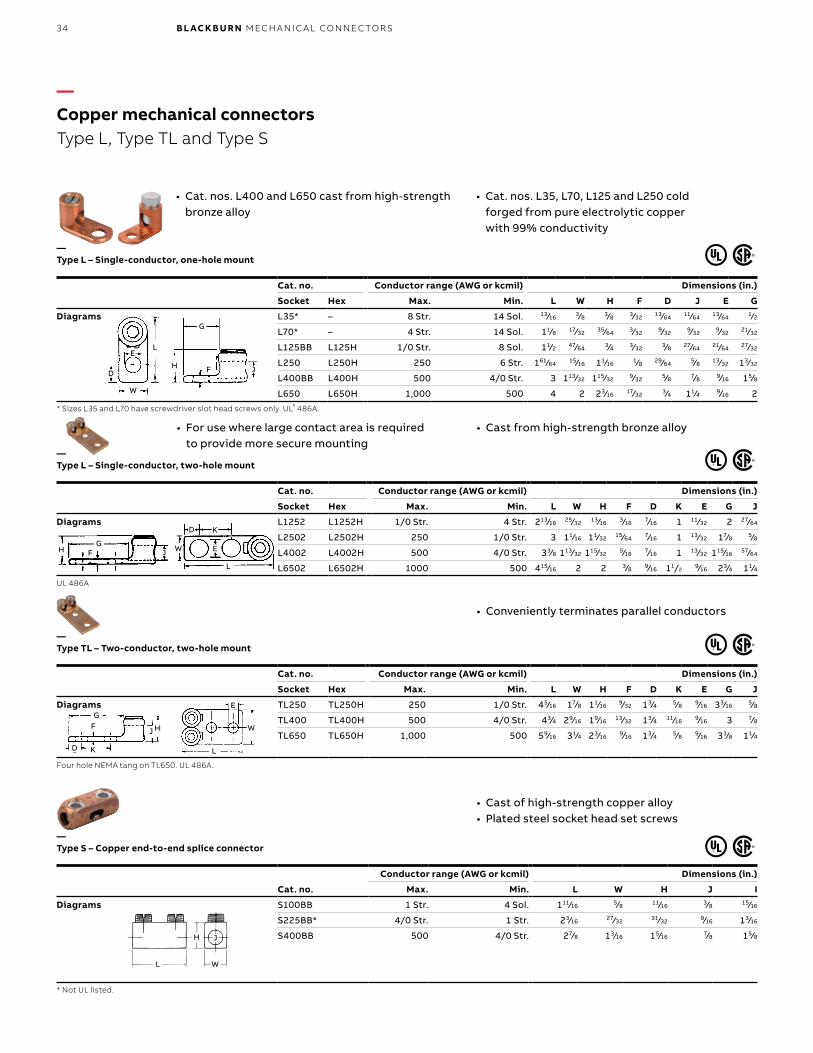
• For use where large contact area is required to provide more secure mounting
• Cast from high-strength bronze alloy
• Cast of high-strength copper alloy• Plated steel socket head set screws
• Cat. nos. L400 and L650 cast from high-strength bronze alloy
• Cat. nos. L35, L70, L125 and L250 cold forged from pure electrolytic copper with 99% conductivity
• Conveniently terminates parallel conductors
Cat. no. Conductor range (AWG or kcmil) Dimensions (in.)
Socket Hex Max. Min. L W H F D K E G J
Diagrams L1252 L1252H 1/0 Str. 4 Str. 213⁄16 25⁄32 13⁄16 3⁄16 7⁄16 1 11⁄32 2 27⁄64
L2502 L2502H 250 1/0 Str. 3 11⁄16 11⁄32 15⁄64 7⁄16 1 13⁄32 17⁄8 5⁄8
L4002 L4002H 500 4/0 Str. 33⁄8 113⁄32 115⁄32 5⁄16 7⁄16 1 13⁄32 115⁄16 57⁄64
L6502 L6502H 1000 500 415⁄16 2 2 3⁄8 9⁄16 11/29⁄16 23⁄4 11⁄4
UL 486A
Cat. no. Conductor range (AWG or kcmil) Dimensions (in.)
Socket Hex Max. Min. L W H F D J E G
Diagrams L35* – 8 Str. 14 Sol. 13⁄16 3⁄8 3⁄8 3⁄32 13⁄64 11⁄64 13⁄64 1⁄2
L70* – 4 Str. 14 Sol. 11⁄8 17⁄32 35⁄64 3⁄32 9⁄32 9⁄32 9⁄32 21⁄32
L125BB L125H 1/0 Str. 8 Sol. 11⁄2 47⁄64 3⁄4 3⁄32 3⁄8 27⁄64 21⁄64 27⁄32
L250 L250H 250 6 Str. 161⁄64 15⁄16 11⁄16 1⁄8 29⁄64 5⁄8 13⁄32 13⁄32
L400BB L400H 500 4/0 Str. 3 113⁄32 115⁄32 9⁄32 5⁄8 7⁄8 9⁄16 15⁄8
L650 L650H 1,000 500 4 2 23⁄16 17⁄32 3⁄4 11⁄4 9⁄16 2
* Sizes L35 and L70 have screwdriver slot head screws only. UL® 486A.
Cat. no. Conductor range (AWG or kcmil) Dimensions (in.)
Socket Hex Max. Min. L W H F D K E G J
Diagrams TL250 TL250H 250 1/0 Str. 45⁄16 17⁄8 11⁄16 9⁄32 13⁄4 5⁄8 9⁄16 33⁄16 5⁄8
TL400 TL400H 500 4/0 Str. 43⁄4 29⁄16 19⁄16 13⁄32 13⁄4 11⁄16 9⁄16 3 7⁄8
TL650 TL650H 1,000 500 59⁄16 31⁄4 23⁄16 9⁄16 13⁄4 5⁄8 9⁄16 33⁄8 11⁄4
Four hole NEMA tang on TL650. UL 486A.
Cat. no.
Conductor range (AWG or kcmil) Dimensions (in.)
Max. Min. L W H J I
Diagrams S100BB 1 Str. 4 Sol. 111⁄16 5⁄8 11⁄16 3⁄8 15⁄16
S225BB* 4/0 Str. 1 Str. 23⁄16 27⁄32 31⁄32 9⁄16 13⁄16
S400BB 500 4/0 Str. 27⁄8 13⁄16 15⁄16 7⁄8 15⁄8
* Not UL listed.
L
E
W
GF HJ
KD
L
H J
W
—Copper mechanical connectorsType L, Type TL and Type S
JG
FH
L
KD
W E
L
G
JFH
LE
W
D
—Type S – Copper end-to-end splice connector
—Type TL – Two-conductor, two-hole mount
—Type L – Single-conductor, two-hole mount
—Type L – Single-conductor, one-hole mount
35CO PPER M ECH A N I C A L CO N N EC TO R S
Cat. no. DescriptionWire
range (AWG)Std.
pkg. qty.
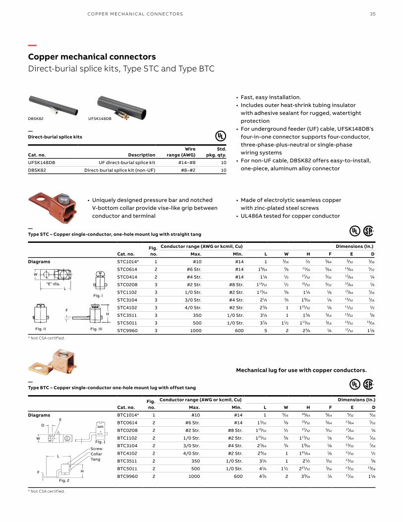
UFSK148DB UF direct-burial splice kit #14–#8 10
DBSK82 Direct-burial splice kit (non-UF) #8–#2 10
• Fast, easy installation.• Includes outer heat-shrink tubing insulator
with adhesive sealant for rugged, watertight protection
• For underground feeder (UF) cable, UFSK148DB’s four-in-one connector supports four-conductor, three-phase-plus-neutral or single-phase wiring systems
• For non-UF cable, DBSK82 offers easy-to-install, one-piece, aluminum alloy connector
DBSK82 UFSK148DB
Cat. no.Fig.no.
Conductor range (AWG or kcmil, Cu) Dimensions (in.)
Max. Min. L W H F E D
STC1014* 1 #10 #14 1 5⁄16 1⁄2 5⁄64 5⁄32 3⁄16
STC0614 2 #6 Str. #14 19⁄64 3⁄8 11⁄16 5⁄64 13⁄64 7⁄32
STC0414 2 #4 Str. #14 11⁄4 1⁄2 27⁄32 3⁄32 17⁄64 1⁄4
STC0208 3 #2 Str. #8 Str. 115⁄32 1⁄2 31⁄32 3⁄32 17⁄64 1⁄4
STC1102 3 1/0 Str. #2 Str. 115⁄16 5⁄8 11⁄4 1⁄8 17⁄64 7⁄16
STC3104 3 3/0 Str. #4 Str. 21⁄4 3⁄4 19⁄16 1⁄8 13⁄32 7⁄16
STC4102 3 4/0 Str. #2 Str. 23⁄8 1 121⁄32 1⁄8 11⁄32 1⁄2
STC3511 3 350 1/0 Str. 31⁄4 1 15⁄8 3⁄16 13⁄32 5⁄8
STC5011 3 500 1/0 Str. 37⁄8 11⁄2 113⁄16 3⁄16 13⁄32 15⁄16
STC9960 3 1000 600 5 2 25⁄8 1⁄4 17⁄32 11⁄8
* Not CSA certified.
Cat. no.Fig.no.
Conductor range (AWG or kcmil, Cu) Dimensions (in.)
Max. Min. L W H F E D
BTC1014* 1 #10 #14 1 5⁄16 43⁄64 5⁄64 5⁄32 3⁄16
BTC0614 2 #6 Str. #14 13⁄32 3⁄8 25⁄32 5⁄64 13⁄64 7⁄32
BTC0208 2 #2 Str. #8 Str. 115⁄32 1⁄2 27⁄32 3⁄32 17⁄64 1⁄4
BTC1102 2 1/0 Str. #2 Str. 125⁄32 5⁄8 113⁄32 1⁄8 17⁄64 7⁄16
BTC3104 2 3/0 Str. #4 Str. 23⁄64 3⁄4 19⁄16 1⁄8 13⁄32 7⁄16
BTC4102 2 4/0 Str. #2 Str. 29⁄16 1 161⁄64 1⁄8 11⁄32 1⁄2
BTC3511 2 350 1/0 Str. 31⁄4 1 21⁄2 3⁄16 13⁄32 5⁄8
BTC5011 2 500 1/0 Str. 41⁄4 11⁄2 221⁄32 3⁄16 13⁄32 15⁄16
BTC9960 2 1000 600 43⁄4 2 39⁄16 1⁄4 17⁄32 11⁄8
* Not CSA certified.
• Uniquely designed pressure bar and notched V-bottom collar provide vise-like grip between conductor and terminal
• Made of electrolytic seamless copper with zinc-plated steel screws
• UL486A tested for copper conductor
Mechanical lug for use with copper conductors.
Fig. 1
Fig. 2
Screw Collar Tang
H
L
F
W
DE
L
W
“E” dia.
Fig. I
Fig. II Fig. III
FH
—Copper mechanical connectorsDirect-burial splice kits, Type STC and Type BTC
—Direct-burial splice kits
—Type STC – Copper single-conductor, one-hole mount lug with straight tang
—Type BTC – Copper single-conductor one-hole mount lug with offset tang
Diagrams
Diagrams
36 B L ACK B U R N M ECH A N I C A L CO N N EC TO R S
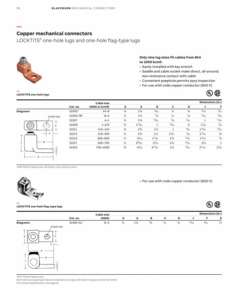
Only nine lug sizes fit cables from #14 to 1000 kcmil. • Easily installed with key wrench• Saddle and cable socket make direct, all-around,
low-resistance contact with cable• Convenient peephole permits easy inspection• For use with code copper conductor (600 V)
Cat. no.Cable size
(AWG or kcmil)
Dimensions (in.)
G A B C D J F
31003† 14–8 1⁄4 11⁄8 9⁄16 1⁄2 1⁄8 17⁄32 9⁄32
31005-TB† 8–4 1⁄4 11⁄8 5⁄8 1⁄2 1⁄8 17⁄32 9⁄32
31007 4–1 1⁄4 15⁄8 13⁄16 5⁄8 7⁄32 1 11⁄32
31009 1–2/0 3⁄8 115⁄16 1 13⁄16 1⁄4 13⁄16 7⁄16
31011 2/0–4/0 3⁄8 23⁄8 11⁄4 1 9⁄32 113⁄32 17⁄32
31013 4/0–300 1⁄2 23⁄4 11⁄2 13⁄16 5⁄16 117⁄32 5⁄8
31015 300–500 1⁄2 31⁄16 111⁄16 13⁄8 11⁄32 113⁄16 3⁄4
31017 500–750 1⁄2 325⁄32 23⁄16 15⁄8 13 ⁄32 21⁄8 1
31019 750–1000 5⁄8 45⁄16 215⁄32 17⁄8 15⁄32 211⁄32 13⁄16
†With filister head screw. All others, hex socket screws.
Cat. no.Cable size
(AWG)
Dimensions (in.)
G A B C D J F E
31005-AL† 8–4 1⁄4 11⁄8 5⁄8 1⁄2 1⁄8 17⁄32 9⁄32 1⁄2
†With filister head screw.Bolt holes and spacings listed are standard, but lugs with blank tongues can be furnished.For torque requirements, see page 41.
• For use with code copper conductor (600 V)
A
G Bolt Size
D
C
BJ
F
C
F
B
D
A
J
G bolt size
G Bolt Size
A
D
C
BJ
F
E
G bolt size
C
F
A
B
D
J
E
—Copper mechanical connectorsLOCKTITE® one-hole lugs and one-hole flag-type lugs
—LOCKTITE one-hole flag-type lugs
—LOCKTITE one-hole lugs
Diagrams
Diagrams
37CO PPER M ECH A N I C A L CO N N EC TO R S
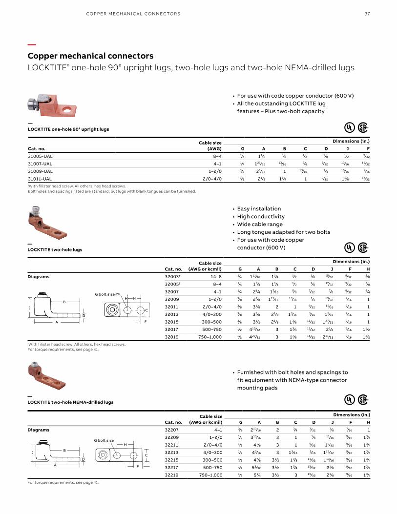
• For use with code copper conductor (600 V)• All the outstanding LOCKTITE lug
features – Plus two-bolt capacity
• Furnished with bolt holes and spacings to fit equipment with NEMA-type connector mounting pads
Cat. no.Cable size
(AWG or kcmil)
Dimensions (in.)
G A B C D J F H
Diagrams 32003† 14–8 1⁄4 111⁄16 11⁄4 1⁄2 1⁄8 15⁄32 9⁄32 5⁄8
32005† 8–4 1⁄4 13⁄4 11⁄4 1⁄2 1⁄8 17⁄32 9⁄32 5⁄8
32007 4–1 1⁄4 21⁄4 17⁄16 5⁄8 7⁄32 7⁄8 9⁄32 3⁄4
32009 1–2/0 3⁄8 27⁄8 115⁄16 13⁄16 1⁄4 13⁄32 7⁄16 1
32011 2/0–4/0 3⁄8 31⁄8 2 1 9⁄32 15⁄16 7⁄16 1
32013 4/0–300 3⁄8 33⁄8 21⁄8 13⁄16 5⁄16 19⁄16 7⁄16 1
32015 300–500 3⁄8 31⁄2 21⁄8 13⁄8 11⁄32 127⁄32 7⁄16 1
32017 500–750 1⁄2 419⁄32 3 13⁄4 13⁄32 21⁄8 9⁄16 11⁄2
32019 750–1,000 1⁄2 427⁄32 3 17⁄8 15⁄32 211⁄32 9⁄16 11⁄2†With filister head screw. All others, hex head screws.For torque requirements, see page 41.
Cat. no.Cable size
(AWG)
Dimensions (in.)
G A B C D J F
31005-UAL† 8–4 1⁄4 11⁄8 5⁄8 1⁄2 1⁄8 1⁄2 9⁄32
31007-UAL 4–1 1⁄4 121⁄32 13⁄16 5⁄8 7⁄32 13⁄16 11⁄32
31009-UAL 1–2/0 3⁄8 21⁄32 1 13⁄16 1⁄4 15⁄16 7⁄16
31011-UAL 2/0–4/0 3⁄8 21⁄2 11⁄4 1 9⁄32 11⁄8 17⁄32
†With filister head screw. All others, hex head screws.Bolt holes and spacings listed are standard, but lugs with blank tongues can be furnished.
Cat. no.Cable size
(AWG or kcmil)
Dimensions (in.)
G A B C D J F H
Diagrams 32207 4–1 3⁄8 213⁄16 2 3⁄4 7⁄32 7⁄8 7⁄16 1
32209 1–2/0 1⁄2 315⁄16 3 1 1⁄4 11⁄16 9⁄16 13⁄4
32211 2/0–4/0 1⁄2 41⁄8 3 1 9⁄32 19⁄32 9⁄16 13⁄4
32213 4/0–300 1⁄2 43⁄16 3 13⁄16 5⁄16 115⁄32 9⁄16 13⁄4
32215 300–500 1⁄2 47⁄8 31⁄2 13⁄8 11⁄32 113⁄16 9⁄16 13⁄4
32217 500–750 1⁄2 53⁄32 31⁄2 13⁄4 13⁄32 21⁄8 9⁄16 13⁄4
32219 750–1,000 1⁄2 51⁄4 31⁄2 3 15⁄32 21⁄8 9⁄16 13⁄4
For torque requirements, see page 41.
H
A
G Bolt Size
D
C
BJ
F
HG bolt size
C
F
H
A
G Bolt Size
D
C
BJ
F
D
B
A
J
—Copper mechanical connectorsLOCKTITE® one-hole 90° upright lugs, two-hole lugs and two-hole NEMA-drilled lugs
—LOCKTITE two-hole NEMA-drilled lugs
—LOCKTITE two-hole lugs
—LOCKTITE one-hole 90° upright lugs
• Easy installation• High conductivity• Wide cable range • Long tongue adapted for two bolts• For use with code copper
conductor (600 V)
H
A
G Bolt Size
D
C
B
J
F
G bolt sizeH
C
F
H
A
G Bolt Size
D
C
B
J
F
B
D
A
J
38 B L ACK B U R N M ECH A N I C A L CO N N EC TO R S
Cat. no.Cable size
(AWG or kcmil) Fig.Bolt size
(in.)
Dimensions (in.)
A B C D E F H J
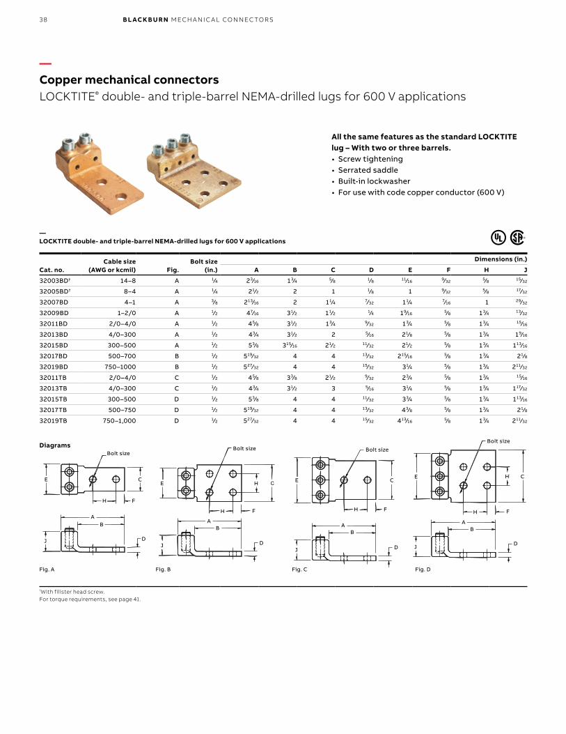
32003BD† 14–8 A 1⁄4 23⁄16 13⁄4 5⁄8 1⁄8 11⁄16 9⁄32 5⁄8 15⁄32
32005BD† 8–4 A 1⁄4 21⁄2 2 1 1⁄8 1 9⁄32 5⁄8 17⁄32
32007BD 4–1 A 3⁄8 213⁄16 2 11⁄4 7⁄32 11⁄4 7⁄16 1 29⁄32
32009BD 1–2/0 A 1⁄2 47⁄16 31⁄2 11⁄2 1⁄4 19⁄16 5⁄8 13⁄4 13⁄32
32011BD 2/0–4/0 A 1⁄2 45⁄8 31⁄2 13⁄4 9⁄32 13⁄4 5⁄8 13⁄4 15⁄16
32013BD 4/0–300 A 1⁄2 43⁄4 31⁄2 2 5⁄16 21⁄8 5⁄8 13⁄4 19⁄16
32015BD 300–500 A 1⁄2 53⁄8 315⁄16 21⁄2 11⁄32 21⁄2 5⁄8 13⁄4 113⁄16
32017BD 500–700 B 1⁄2 519⁄32 4 4 13⁄32 215⁄16 5⁄8 13⁄4 21⁄8
32019BD 750–1000 B 1⁄2 527⁄32 4 4 15⁄32 31⁄4 5⁄8 13⁄4 211⁄32
32011TB 2/0–4/0 C 1⁄2 45⁄8 33⁄8 21⁄2 9⁄32 23⁄4 5⁄8 13⁄4 15⁄16
32013TB 4/0–300 C 1⁄2 43⁄4 31⁄2 3 5⁄16 31⁄4 5⁄8 13⁄4 117⁄32
32015TB 300–500 D 1⁄2 53⁄8 4 4 11⁄32 33⁄4 5⁄8 13⁄4 113⁄16
32017TB 500–750 D 1⁄2 519⁄32 4 4 13⁄32 43⁄8 5⁄8 13⁄4 21⁄8
32019TB 750–1,000 D 1⁄2 527⁄32 4 4 15⁄32 413⁄16 5⁄8 13⁄4 211⁄32
†With filister head screw. For torque requirements, see page 41.
All the same features as the standard LOCKTITE lug – With two or three barrels.• Screw tightening• Serrated saddle• Built-in lockwasher• For use with code copper conductor (600 V)
—Copper mechanical connectorsLOCKTITE® double- and triple-barrel NEMA-drilled lugs for 600 V applications
—LOCKTITE double- and triple-barrel NEMA-drilled lugs for 600 V applications
Bolt Size
E
AB
D
FH
C
J
Fig. A Fig. B
Bolt Size
E
AB
D
FH
C
J
Fig. C Fig. D
C
FH
E
Bolt sizeBolt size
AB
DJ
C
Bolt Size
E
AB
D
FH
C
J
H
Bolt size
E H
H F
D
AB
J D
AB
J
E C
H F
Bolt Size
E
AB
D
FH
C
J
H
Bolt size
E CH
FH
D
AB
J
Diagrams
39CO PPER M ECH A N I C A L CO N N EC TO R S
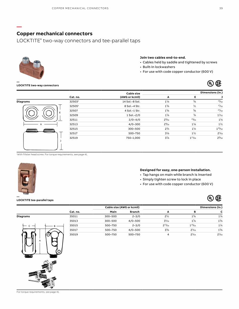
Join two cables end-to-end.• Cables held by saddle and tightened by screws• Built-in lockwashers• For use with code copper conductor (600 V)
Designed for easy, one-person installation.• Tap hangs on main while branch is inserted• Simply tighten screw to lock in place• For use with code copper conductor (600 V)
Cat. no.Cable size
(AWG or kcmil)
Dimensions (in.)
A E J
Diagrams 32503† 14 Sol.–8 Sol. 11⁄8 3⁄8 15⁄32
32505† 8 Sol.–4 Str. 13⁄8 1⁄2 17⁄32
32507 4 Sol.–1 Str. 15⁄8 5⁄8 27⁄32
32509 1 Sol.–2/0 17⁄8 3⁄4 11⁄32
32511 2/0–4/0 25⁄16 15⁄16 11⁄4
32513 4/0–300 29⁄16 11⁄8 11⁄2
32515 300–500 23⁄4 11⁄4 125⁄32
32517 500–750 31⁄8 11⁄2 21⁄16
32519 750–1,000 37⁄8 111⁄16 29⁄32
†With filister head screw. For torque requirements, see page 41.
Cat. no.
Cable size (AWG or kcmil) Dimensions (in.)
Main Branch A B C
Diagrams 35011 300–500 2–3/0 21⁄2 13⁄4 11⁄4
35013 300–500 4/0–500 31⁄16 17⁄8 15⁄8
35015 500–750 2–3/0 213⁄16 115⁄16 11⁄4
35017 500–750 4/0–500 33⁄8 21⁄16 15⁄8
35019 500–750 500–750 4 21⁄16 21⁄16
For torque requirements, see page 41.
A
E
J
E
A
J
A
C B
A
BC
—Copper mechanical connectorsLOCKTITE® two-way connectors and tee-parallel taps
—LOCKTITE tee-parallel taps
—LOCKTITE two-way connectors
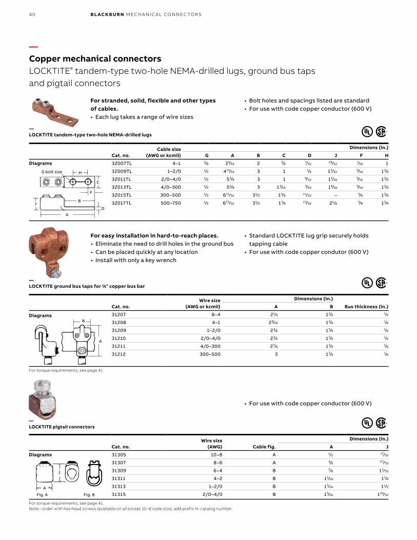
40 B L ACK B U R N M ECH A N I C A L CO N N EC TO R S
Cat. no.Wire size
(AWG or kcmil)
Dimensions (in.)
Bus thickness (in.)A B
31207 8–4 21⁄4 13⁄4 1⁄4
31208 4–1 29⁄16 13⁄4 1⁄4
31209 1–2/0 23⁄4 13⁄4 1⁄4
31210 2/0–4/0 23⁄4 13⁄4 1⁄4
31211 4/0–300 27⁄8 13⁄4 1⁄4
31212 300–500 3 13⁄4 1⁄4
For torque requirements, see page 41.
For stranded, solid, flexible and other types of cables.• Each lug takes a range of wire sizes
• Bolt holes and spacings listed are standard• For use with code copper conductor (600 V)
For easy installation in hard-to-reach places.• Eliminate the need to drill holes in the ground bus• Can be placed quickly at any location• Install with only a key wrench
• Standard LOCKTITE lug grip securely holds tapping cable
• For use with code copper condutor (600 V)
• For use with code copper conductor (600 V)
Cat. no.Cable size
(AWG or kcmil)
Dimensions (in.)
G A B C D J F H
32007TL 4–1 3⁄8 39⁄16 2 3⁄4 7⁄32 29⁄32 7⁄16 1
32009TL 1–2/0 1⁄2 415⁄16 3 1 1⁄4 13⁄32 9⁄16 13⁄4
32011TL 2/0–4/0 1⁄2 53⁄8 3 1 9⁄32 15⁄16 9⁄16 13⁄4
32013TL 4/0–300 1⁄2 55⁄8 3 13⁄16 5⁄16 19⁄16 9⁄16 13⁄4
32015TL 300–500 1⁄2 611⁄32 31⁄2 13⁄8 11⁄32 – 5⁄8 13⁄4
32017TL 500–750 1⁄2 623⁄32 31⁄2 13⁄4 13⁄32 21⁄8 5⁄8 13⁄4
Cat. no.Wire size
(AWG) Cable fig.
Dimensions (in.)
A J
31305 10–8 A 1⁄2 17⁄32
31307 8–6 A 3⁄4 27⁄32
31309 6–4 B 7⁄8 11⁄32
31311 4–2 B 11⁄16 11⁄4
31313 1–2/0 B 13⁄16 11⁄2
31315 2/0–4/0 B 15⁄16 125⁄32
For torque requirements, see page 41.Note:–order with hex head screws (available on all except 10–8 code size), add prefix H–catalog number.
G Bolt Size
J
H
C
DA
B
F
B
A
H
C
F
DJ
G bolt size
B
A
B
A
J
A Fig. B
J
AFig. A
J
A
—Copper mechanical connectorsLOCKTITE® tandem-type two-hole NEMA-drilled lugs, ground bus taps and pigtail connectors
—LOCKTITE pigtail connectors
—LOCKTITE ground bus taps for 1⁄4" copper bus bar
—LOCKTITE tandem-type two-hole NEMA-drilled lugs
Diagrams
Diagrams
Diagrams
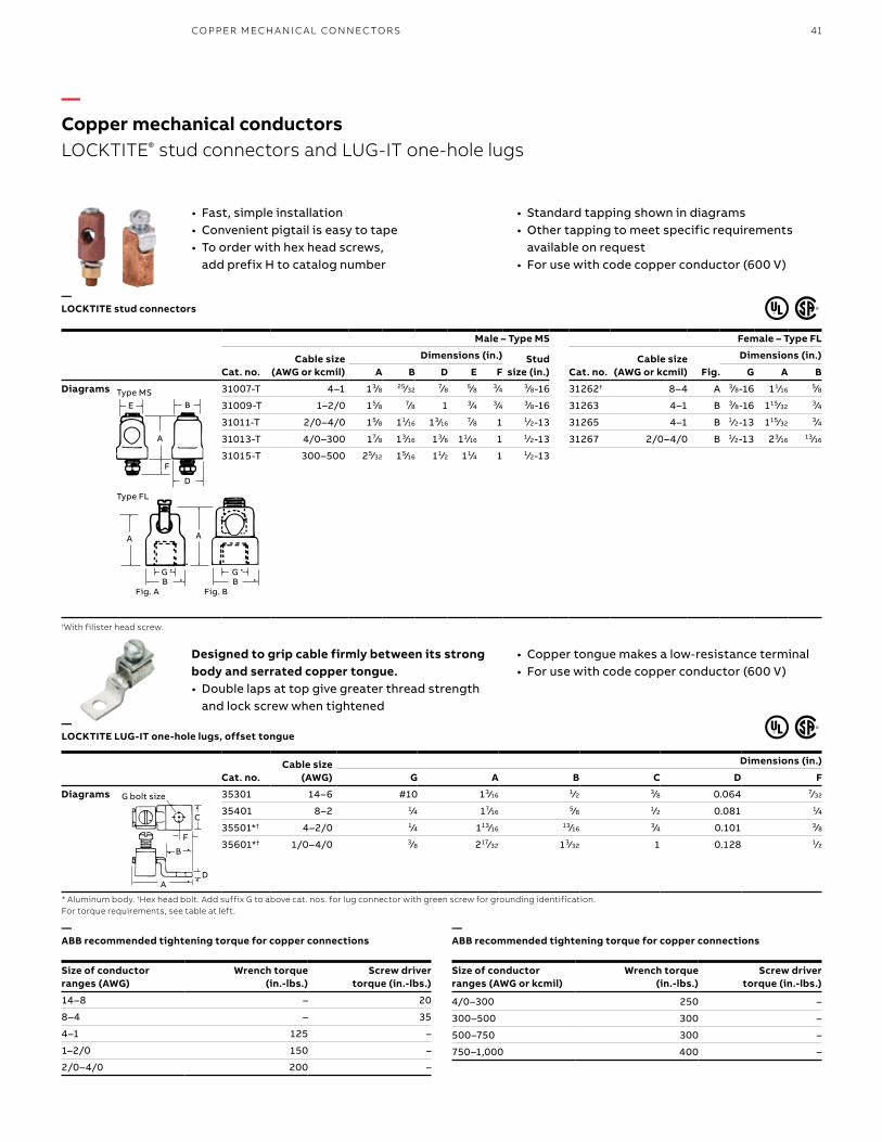
41CO PPER M ECH A N I C A L CO N N EC TO R S
Designed to grip cable firmly between its strong body and serrated copper tongue.• Double laps at top give greater thread strength
and lock screw when tightened
• Copper tongue makes a low-resistance terminal• For use with code copper conductor (600 V)
—LOCKTITE stud connectors
Male – Type MS Female – Type FL
Cat. no.Cable size
(AWG or kcmil)
Dimensions (in.) Studsize (in.) Cat. no.
Cable size (AWG or kcmil) Fig.
Dimensions (in.)
A B D E F G A B
Diagrams 31007-T 4–1 13⁄8 25⁄32 7⁄8 5⁄8 3⁄4 3⁄8-16 31262† 8–4 A 3⁄8-16 11⁄16 5⁄8
31009-T 1–2/0 15⁄8 7⁄8 1 3⁄4 3⁄4 3⁄8-16 31263 4–1 B 3⁄8-16 115⁄32 3⁄4
31011-T 2/0–4/0 15⁄8 11⁄16 13⁄16 7⁄8 1 1⁄2-13 31265 4–1 B 1⁄2-13 115⁄32 3⁄4
31013-T 4/0–300 17⁄8 13⁄16 13⁄8 11⁄16 1 1⁄2-13 31267 2/0–4/0 B 1⁄2-13 23⁄16 13⁄16
31015-T 300–500 25⁄32 15⁄16 11⁄2 11⁄4 1 1⁄2-13
†With filister head screw.
• Fast, simple installation• Convenient pigtail is easy to tape• To order with hex head screws,
add prefix H to catalog number
• Standard tapping shown in diagrams• Other tapping to meet specific requirements
available on request• For use with code copper conductor (600 V)
—ABB recommended tightening torque for copper connections
Size of conductor ranges (AWG)
Wrench torque (in.-lbs.)
Screw driver torque (in.-lbs.)
14–8 – 20
8–4 – 35
4–1 125 –
1–2/0 150 –
2/0–4/0 200 –
Cat. no.Cable size
(AWG)
Dimensions (in.)
G A B C D F
35301 14–6 #10 13⁄16 1⁄2 3⁄8 0.064 7⁄32
35401 8–2 1⁄4 17⁄16 5⁄8 1⁄2 0.081 1⁄4
35501*† 4–2/0 1⁄4 113⁄16 13⁄16 3⁄4 0.101 3⁄8
35601*† 1/0–4/0 3⁄8 217⁄32 13⁄32 1 0.128 1⁄2
D
F
A
E BBE
A
F
D
GB
A A
GB
Fig. A Fig. BBB
AA
GG
D
F
B
C
A
C
F
B
DA
G bolt size
—Copper mechanical conductorsLOCKTITE® stud connectors and LUG-IT one-hole lugs
—LOCKTITE LUG-IT one-hole lugs, offset tongue
* Aluminum body. †Hex head bolt. Add suffix G to above cat. nos. for lug connec tor with green screw for grounding identification.For torque requirements, see table at left.
4/0–300 250 –
300–500 300 –
500–750 300 –
750–1,000 400 –
—ABB recommended tightening torque for copper connections
Size of conductor ranges (AWG or kcmil)
Wrench torque (in.-lbs.)
Screw driver torque (in.-lbs.)
Diagrams
Type MS
Type FL
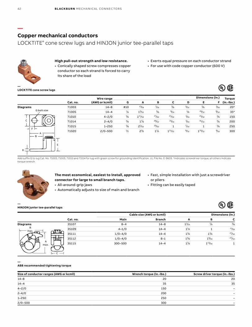
42 B L ACK B U R N M ECH A N I C A L CO N N EC TO R S
— ABB recommended tightening torque
Size of conductor ranges (AWG or kcmil) Wrench torque (in.-lbs.) Screw driver torque (in.-lbs.)
14–8 20 20
14–4 35 35
4–2/0 150 –
2–4/0 200 –
1–250 250 –
2/0–500 300 –
High pull-out strength and low resistance.• Conically shaped screw compresses copper
conductor so each strand is forced to carry its share of the load
• Exerts equal pressure on each conductor strand• For use with code copper conductor (600 V)
Cat. no.Wire range
(AWG or kcmil)
Dimensions (in.) Torque(in.-lbs.)G A B C D E F
Diagrams 71003 14–8 #10 13⁄16 7⁄16 3⁄8 3⁄32 3⁄8 3⁄16 20*
71005 14–4 1⁄4 15⁄32 5⁄8 9⁄16 1⁄8 19⁄32 9⁄32 35*
71010 4–2/0 3⁄8 121⁄32 27⁄32 23⁄32 3⁄16 25⁄32 3⁄8 150
71014 2–4/0 3⁄8 17⁄8 29⁄32 15⁄16 3⁄16 31⁄32 3⁄8 200
71015 1–250 3⁄8 21⁄32 29⁄32 1 7⁄32 1 3⁄8 250
71020 2/0–500 1⁄2 23⁄4 11⁄4 111⁄32 9⁄32 115⁄32 9⁄16 300
Add suffix G to lug Cat. No. 71003, 71005, 71010 and 71014 for lug with green screw for grounding identification. UL File No. E-9609. *Indicates screwdriver torque; all others indicate torque wrench.
Cat. no.
Cable size (AWG or kcmil) Dimensions (in.)
Main Branch A B C
Diagrams 35107 8–4 14–8 11⁄16 7⁄8 5⁄8
35109 4–1/0 14–4 11⁄4 1 11⁄16
35111 1/0–4/0 14–4 13⁄4 13⁄8 27⁄32
35112 1/0–4/0 8–1 15⁄8 19⁄16 27⁄32
35115 300–500 14–4 17⁄8 113⁄16 1
The most economical, easiest to install, approved connector for large to small branch taps.• All-around-grip jaws• Automatically adjusts to size of main and branch
• Fast, simple installation with just a screwdriver or pliers
• Fitting can be easily taped
B�max.
A�max.
C
B�max.
A�max.
CC
Amax.
Bmax.
G Bolt Size
E
AF
B
C
D
E
AB
D
F
C
G bolt size
—Copper mechanical conductorsLOCKTITE® cone screw lugs and HINJON junior tee-parallel taps
—HINJON junior tee-parallel taps
—LOCKTITE cone screw lugs
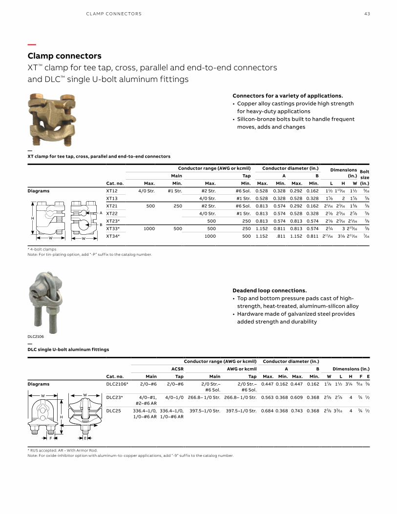
43CL A M P CO N N EC TO R S
Cat. no.
Conductor range (AWG or kcmil) Conductor diameter (in.) Dimensions (in.)
Boltsize(in.)
Main Tap A B
Max. Min. Max. Min. Max. Min. Max. Min. L H W
Diagrams XT12 4/0 Str. #1 Str. #2 Str. #6 Sol. 0.528 0.328 0.292 0.162 11⁄2 113⁄16 11⁄2 5⁄16
XT13 4/0 Str. #1 Str. 0.528 0.328 0.528 0.328 17⁄8 2 17⁄8 3⁄8
XT21 500 250 #2 Str. #6 Sol. 0.813 0.574 0.292 0.162 21⁄16 23⁄16 15⁄8 3⁄8
XT22 4/0 Str. #1 Str. 0.813 0.574 0.528 0.328 21⁄8 23⁄16 27⁄8 3⁄8
XT23* 500 250 0.813 0.574 0.813 0.574 21⁄8 23⁄16 21⁄26 3⁄8
XT33* 1000 500 500 250 1.152 0.811 0.813 0.574 21⁄4 3 215⁄16 3⁄8
XT34* 1000 500 1.152 .811 1.152 0.811 211⁄16 31⁄8 211⁄16 7⁄16
* 4-bolt clampsNote: For tin-plating option, add “-P” suffix to the catalog number.
Connectors for a variety of applications.• Copper alloy castings provide high strength
for heavy-duty applications• Silicon-bronze bolts built to handle frequent
moves, adds and changes
DLC2106
H
W W
A
B
Cat. no.
Conductor range (AWG or kcmil) Conductor diameter (in.)
Dimensions (in.)ACSR AWG or kcmil A B
Main Tap Main Tap Max. Min. Max. Min. W L H F E
Diagrams DLC2106* 2/0–#6 2/0–#6 2/0 Str.– #6 Sol.
2/0 Str.– #6 Sol.
0.447 0.162 0.447 0.162 17⁄8 11⁄2 31⁄4 9⁄16 3⁄8
DLC23* 4/0–#1, #2–#6 AR
4/0–1/0 266.8– 1/0 Str. 266.8– 1/0 Str. 0.563 0.368 0.609 0.368 23⁄8 27⁄8 4 3⁄4 1⁄2
DLC25 336.4–1/0, 1/0–#6 AR
336.4–1/0, 1/0–#6 AR
397.5–1/0 Str. 397.5–1/0 Str. 0.684 0.368 0.743 0.368 23⁄8 33⁄16 4 3⁄4 1⁄2
* RUS accepted. AR – With Armor Rod.Note: For oxide-inhibitor option with aluminum-to-copper applications, add “-9” suffix to the catalog number.
W
H
F E
W
Deadend loop connections.• Top and bottom pressure pads cast of high-
strength, heat-treated, aluminum-silicon alloy• Hardware made of galvanized steel provides
added strength and durability
—Clamp connectorsXT™ clamp for tee tap, cross, parallel and end-to-end connectors and DLC™ single U-bolt aluminum fittings
—DLC single U-bolt aluminum fittings
—XT clamp for tee tap, cross, parallel and end-to-end connectors
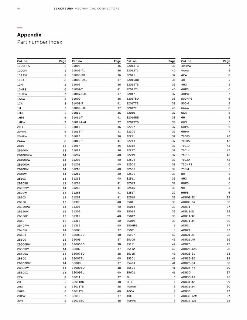
44 B L ACK B U R N M ECH A N I C A L CO N N EC TO R S
—AppendixPart number index
Cat. no. Page
1000HPS 6
1000M 5
10AAW 8
10CA 8
10H 5
10HPS 6
10HPW 7
1AAW 8
1CA 8
1H 5
1H3 5
1HPS 6
1HPW 7
20H 5
20HPS 6
20HPW 7
2AAW 8
2B10 13
2B1000 13
2B1000PW 14
2B1000W 14
2B1000X 13
2B10PW 14
2B10W 14
2B10X 13
2B20BB 13
2B20PW 14
2B20W 14
2B20X 13
2B350 13
2B350PW 14
2B350W 14
2B350X 13
2B40 13
2B40PW 14
2B40W 14
2B40X 13
2B500 13
2B500PW 14
2B500W 14
2B500X 13
2B800 13
2B800PW 14
2B800W 14
2B800X 13
2CA 8
2H 5
2H3 5
2HPS 6
2HPW 7
30H 5
Cat. no. Page
31003 36
31005-AL 36
31005-TB 36
31005-UAL 37
31007 36
31007-T 41
31007-UAL 37
31009 36
31009-T 41
31009-UAL 37
31011 36
31011-T 41
31011-UAL 37
31013 36
31013-T 41
31015 36
31015-T 41
31017 36
31019 36
31207 40
31208 40
31209 40
31210 40
31211 40
31212 40
31262 41
31263 41
31265 41
31267 41
31305 40
31307 40
31309 40
31311 40
31313 40
31315 40
32003 37
32003BD 38
32005 37
32005BD 38
32007 37
32007BD 38
32007TL 40
32009 37
32009BD 38
32009TL 40
32011 37
32011BD 38
32011TB 38
32011TL 40
32013 37
32013BD 38
Cat. no. Page
32013TB 38
32013TL 40
32015 37
32015BD 38
32015TB 38
32015TL 40
32017 37
32017BD 38
32017TB 38
32017TL 40
32019 37
32019BD 38
32019TB 38
32207 37
32209 37
32211 37
32213 37
32215 37
32217 37
32219 37
32503 39
32505 39
32507 39
32509 39
32511 39
32513 39
32515 39
32517 39
32519 39
35011 39
35013 39
35015 39
35017 39
35019 39
350HPS 6
350M 5
35107 42
35109 42
35111 42
35112 42
35115 42
35301 41
35401 41
35501 41
35601 41
3H 5
3H3 5
40AAW 8
40CA 8
40H 5
40HPS 6
Cat. no. Page
40HPW 7
4AAW 8
4CA 8
4H 5
4H3 5
4HPS 6
4HPW 7
500HPS 6
500M 5
6AAW 8
6CA 8
6H 5
6H3 5
6HPS 6
6HPW 7
71003 42
71005 42
71010 42
71014 42
71015 42
71020 42
750HPS 6
750M 5
8H 5
8H3 5
8HPS 6
9H 5
9HPS 6
ADR02-32 29
ADR02-34 30
ADR11 27
ADR11-21 28
ADR11-32 29
ADR11-34 30
ADR2 27
ADR21 27
ADR21-21 28
ADR21-AR 26
ADR25 27
ADR25-12S 28
ADR25-21 28
ADR25-32 29
ADR25-34 30
ADR25-44 30
ADR30 27
ADR30-AR 26
ADR31-32 29
ADR31-34 30
ADR35 27
ADR35-12# 27
ADR35-12S 28
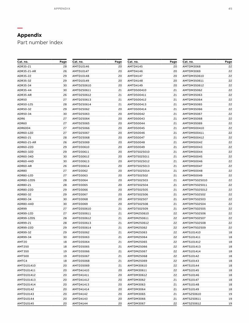
45A PPEN D I X
Cat. no. Page
ADR35-21 28
ADR35-21-AR 26
ADR35-22 29
ADR35-32 29
ADR35-34 30
ADR35-44 30
ADR35-AR 26
ADR50 27
ADR50-12S 28
ADR50-32 29
ADR50-34 30
ADR6 27
ADR60 27
ADR6004 27
ADR60-12D 27
ADR60-21 28
ADR60-21-AR 26
ADR60-22D 29
ADR60-32D 29
ADR60-34D 30
ADR60-44D 30
ADR60-AR 26
ADR80 27
ADR80-12D 27
ADR80-12DS 28
ADR80-21 28
ADR80-22D 29
ADR80-32 29
ADR80-34 30
ADR80-44D 30
ADR99 27
ADR99-12D 27
ADR99-12DS 28
ADR99-21 28
ADR99-22D 29
ADR99-32 29
ADR99-34 30
AMT20 18
AMT250 18
AMT350 19
AMT500 19
AMTC4 18
AMTD101410 20
AMTD101411 20
AMTD101412 20
AMTD101413 20
AMTD101414 20
AMTD10142 20
AMTD10143 20
AMTD10144 20
AMTD10145 20
Cat. no. Page
AMTD10146 20
AMTD10147 20
AMTD10148 20
AMTD10149 20
AMTD250610 20
AMTD250611 21
AMTD250612 21
AMTD250613 21
AMTD250614 21
AMTD25062 20
AMTD25063 20
AMTD25064 20
AMTD25065 20
AMTD25066 20
AMTD25067 20
AMTD25068 20
AMTD25069 20
AMTD30610 20
AMTD30611 20
AMTD30612 20
AMTD30613 20
AMTD30614 20
AMTD3062 20
AMTD3063 20
AMTD3064 20
AMTD3065 20
AMTD3066 20
AMTD3067 20
AMTD3068 20
AMTD3069 20
AMTD350610 21
AMTD350611 21
AMTD350612 21
AMTD350613 21
AMTD350614 21
AMTD35062 21
AMTD35063 21
AMTD35064 21
AMTD35065 21
AMTD35066 21
AMTD35067 21
AMTD35068 21
AMTD35069 21
AMTD41410 20
AMTD41411 20
AMTD41412 20
AMTD41413 20
AMTD41414 20
AMTD4142 20
AMTD4143 20
AMTD4144 20
Cat. no. Page
AMTD4145 20
AMTD4146 20
AMTD4147 20
AMTD4148 20
AMTD4149 20
AMTD500410 21
AMTD500411 21
AMTD500412 21
AMTD500413 21
AMTD500414 21
AMTD50042 21
AMTD50043 21
AMTD50044 21
AMTD50045 21
AMTD50046 21
AMTD50047 21
AMTD50048 21
AMTD50049 21
AMTD75025010 21
AMTD75025011 21
AMTD75025012 21
AMTD75025013 21
AMTD75025014 21
AMTD7502502 21
AMTD7502503 21
AMTD7502504 21
AMTD7502505 21
AMTD7502506 21
AMTD7502507 21
AMTD7502508 21
AMTD7502509 21
AMTDM250610 22
AMTDM250611 22
AMTDM250612 22
AMTDM25062 22
AMTDM25063 22
AMTDM25064 22
AMTDM25065 22
AMTDM25066 22
AMTDM25067 22
AMTDM25068 22
AMTDM25069 22
AMTDM30610 22
AMTDM30611 22
AMTDM30612 22
AMTDM3062 21
AMTDM3063 21
AMTDM3064 21
AMTDM3065 21
AMTDM3066 21
AMTDM3067 22
Cat. no. Page
AMTDM3068 22
AMTDM3069 22
AMTDM350610 22
AMTDM350611 22
AMTDM350612 22
AMTDM35062 22
AMTDM35063 22
AMTDM35064 22
AMTDM35065 22
AMTDM35066 22
AMTDM35067 22
AMTDM35068 22
AMTDM35069 22
AMTDM500410 22
AMTDM500411 22
AMTDM500412 22
AMTDM50042 22
AMTDM50043 22
AMTDM50044 22
AMTDM50045 22
AMTDM50046 22
AMTDM50047 22
AMTDM50048 22
AMTDM50049 22
AMTDM75025010 22
AMTDM75025011 22
AMTDM75025012 22
AMTDM7502502 22
AMTDM7502503 22
AMTDM7502504 22
AMTDM7502505 22
AMTDM7502506 22
AMTDM7502507 22
AMTDM7502508 22
AMTDM7502509 22
AMTS101410 18
AMTS101411 18
AMTS101412 18
AMTS101413 18
AMTS101414 18
AMTS10142 18
AMTS10143 18
AMTS10144 18
AMTS10145 18
AMTS10146 18
AMTS10147 18
AMTS10148 18
AMTS10149 18
AMTS250610 19
AMTS250611 19
AMTS250612 19
—AppendixPart number index
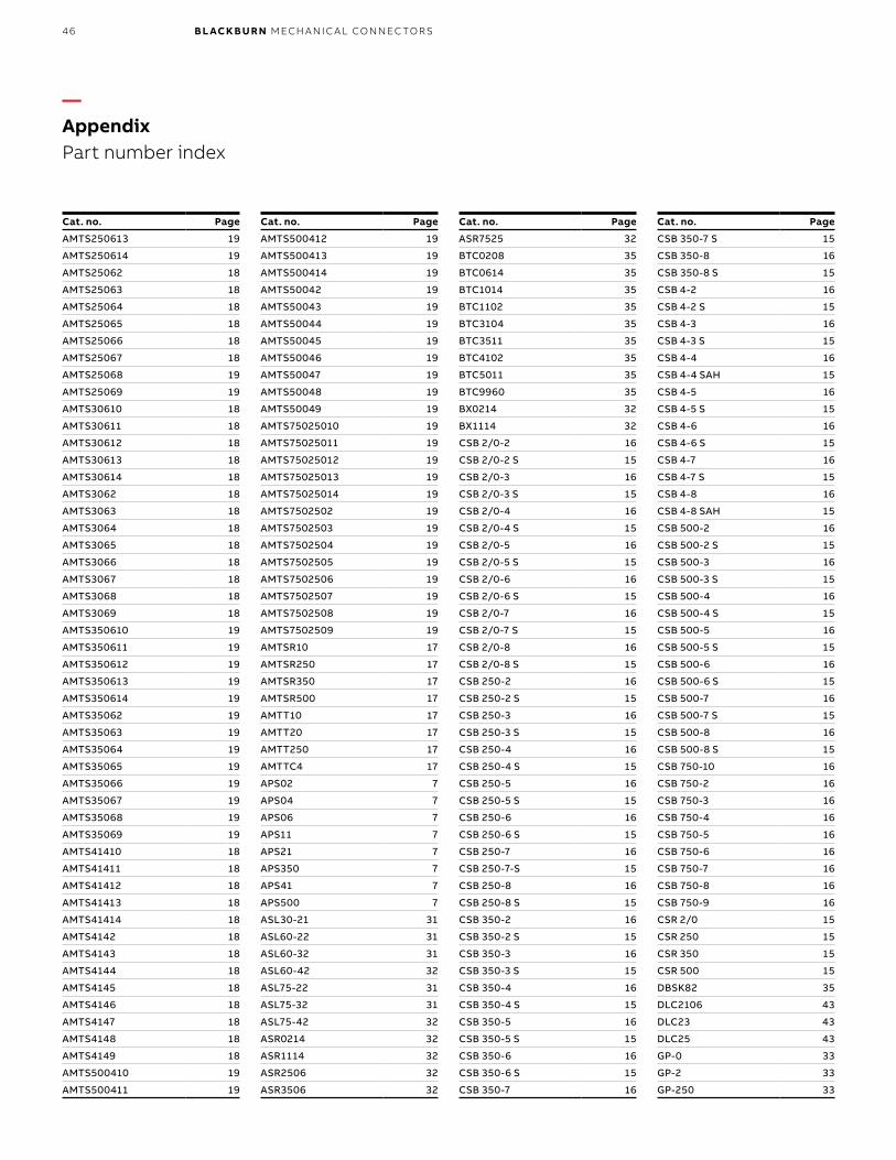
46 B L ACK B U R N M ECH A N I C A L CO N N EC TO R S
Cat. no. Page
AMTS250613 19
AMTS250614 19
AMTS25062 18
AMTS25063 18
AMTS25064 18
AMTS25065 18
AMTS25066 18
AMTS25067 18
AMTS25068 19
AMTS25069 19
AMTS30610 18
AMTS30611 18
AMTS30612 18
AMTS30613 18
AMTS30614 18
AMTS3062 18
AMTS3063 18
AMTS3064 18
AMTS3065 18
AMTS3066 18
AMTS3067 18
AMTS3068 18
AMTS3069 18
AMTS350610 19
AMTS350611 19
AMTS350612 19
AMTS350613 19
AMTS350614 19
AMTS35062 19
AMTS35063 19
AMTS35064 19
AMTS35065 19
AMTS35066 19
AMTS35067 19
AMTS35068 19
AMTS35069 19
AMTS41410 18
AMTS41411 18
AMTS41412 18
AMTS41413 18
AMTS41414 18
AMTS4142 18
AMTS4143 18
AMTS4144 18
AMTS4145 18
AMTS4146 18
AMTS4147 18
AMTS4148 18
AMTS4149 18
AMTS500410 19
AMTS500411 19
Cat. no. Page
AMTS500412 19
AMTS500413 19
AMTS500414 19
AMTS50042 19
AMTS50043 19
AMTS50044 19
AMTS50045 19
AMTS50046 19
AMTS50047 19
AMTS50048 19
AMTS50049 19
AMTS75025010 19
AMTS75025011 19
AMTS75025012 19
AMTS75025013 19
AMTS75025014 19
AMTS7502502 19
AMTS7502503 19
AMTS7502504 19
AMTS7502505 19
AMTS7502506 19
AMTS7502507 19
AMTS7502508 19
AMTS7502509 19
AMTSR10 17
AMTSR250 17
AMTSR350 17
AMTSR500 17
AMTT10 17
AMTT20 17
AMTT250 17
AMTTC4 17
APS02 7
APS04 7
APS06 7
APS11 7
APS21 7
APS350 7
APS41 7
APS500 7
ASL30-21 31
ASL60-22 31
ASL60-32 31
ASL60-42 32
ASL75-22 31
ASL75-32 31
ASL75-42 32
ASR0214 32
ASR1114 32
ASR2506 32
ASR3506 32
Cat. no. Page
ASR7525 32
BTC0208 35
BTC0614 35
BTC1014 35
BTC1102 35
BTC3104 35
BTC3511 35
BTC4102 35
BTC5011 35
BTC9960 35
BX0214 32
BX1114 32
CSB 2/0-2 16
CSB 2/0-2 S 15
CSB 2/0-3 16
CSB 2/0-3 S 15
CSB 2/0-4 16
CSB 2/0-4 S 15
CSB 2/0-5 16
CSB 2/0-5 S 15
CSB 2/0-6 16
CSB 2/0-6 S 15
CSB 2/0-7 16
CSB 2/0-7 S 15
CSB 2/0-8 16
CSB 2/0-8 S 15
CSB 250-2 16
CSB 250-2 S 15
CSB 250-3 16
CSB 250-3 S 15
CSB 250-4 16
CSB 250-4 S 15
CSB 250-5 16
CSB 250-5 S 15
CSB 250-6 16
CSB 250-6 S 15
CSB 250-7 16
CSB 250-7-S 15
CSB 250-8 16
CSB 250-8 S 15
CSB 350-2 16
CSB 350-2 S 15
CSB 350-3 16
CSB 350-3 S 15
CSB 350-4 16
CSB 350-4 S 15
CSB 350-5 16
CSB 350-5 S 15
CSB 350-6 16
CSB 350-6 S 15
CSB 350-7 16
Cat. no. Page
CSB 350-7 S 15
CSB 350-8 16
CSB 350-8 S 15
CSB 4-2 16
CSB 4-2 S 15
CSB 4-3 16
CSB 4-3 S 15
CSB 4-4 16
CSB 4-4 SAH 15
CSB 4-5 16
CSB 4-5 S 15
CSB 4-6 16
CSB 4-6 S 15
CSB 4-7 16
CSB 4-7 S 15
CSB 4-8 16
CSB 4-8 SAH 15
CSB 500-2 16
CSB 500-2 S 15
CSB 500-3 16
CSB 500-3 S 15
CSB 500-4 16
CSB 500-4 S 15
CSB 500-5 16
CSB 500-5 S 15
CSB 500-6 16
CSB 500-6 S 15
CSB 500-7 16
CSB 500-7 S 15
CSB 500-8 16
CSB 500-8 S 15
CSB 750-10 16
CSB 750-2 16
CSB 750-3 16
CSB 750-4 16
CSB 750-5 16
CSB 750-6 16
CSB 750-7 16
CSB 750-8 16
CSB 750-9 16
CSR 2/0 15
CSR 250 15
CSR 350 15
CSR 500 15
DBSK82 35
DLC2106 43
DLC23 43
DLC25 43
GP-0 33
GP-2 33
GP-250 33
—AppendixPart number index
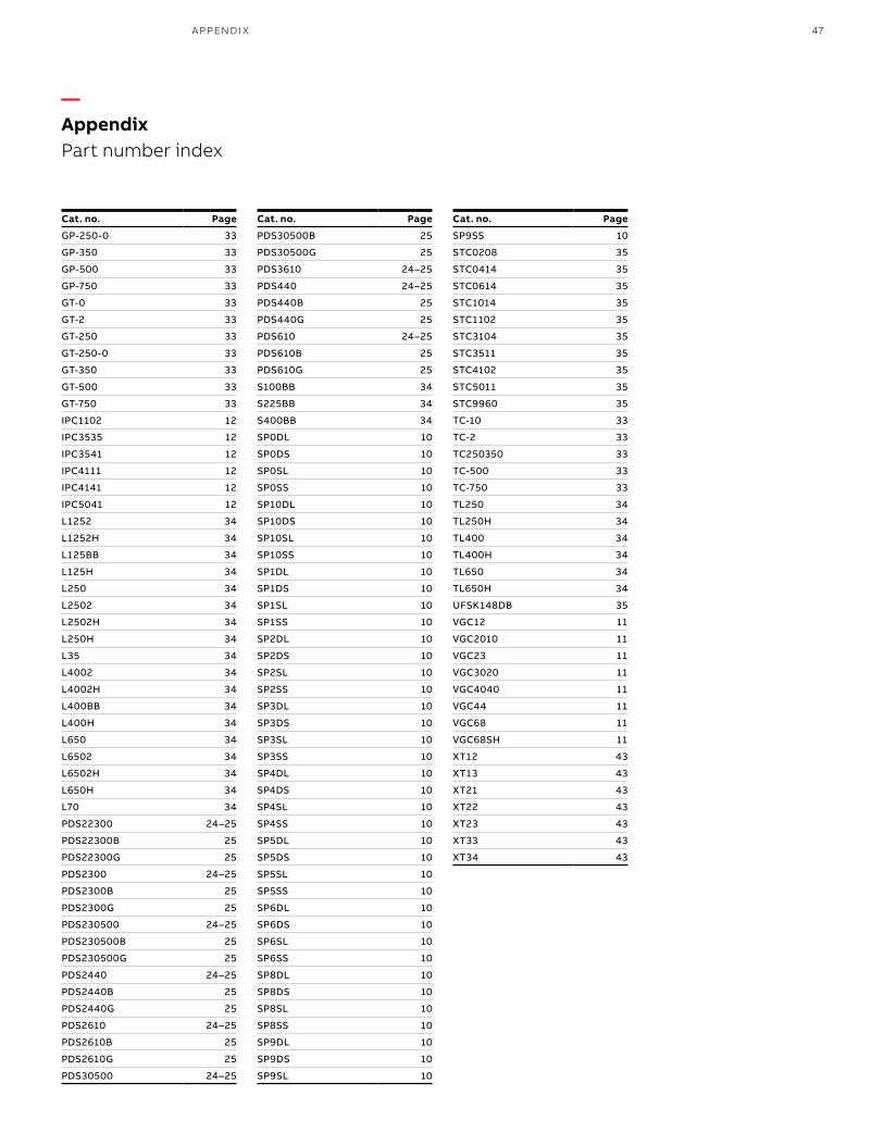
47
Cat. no. Page
GP-250-0 33
GP-350 33
GP-500 33
GP-750 33
GT-0 33
GT-2 33
GT-250 33
GT-250-0 33
GT-350 33
GT-500 33
GT-750 33
IPC1102 12
IPC3535 12
IPC3541 12
IPC4111 12
IPC4141 12
IPC5041 12
L1252 34
L1252H 34
L125BB 34
L125H 34
L250 34
L2502 34
L2502H 34
L250H 34
L35 34
L4002 34
L4002H 34
L400BB 34
L400H 34
L650 34
L6502 34
L6502H 34
L650H 34
L70 34
PDS22300 24–25
PDS22300B 25
PDS22300G 25
PDS2300 24–25
PDS2300B 25
PDS2300G 25
PDS230500 24–25
PDS230500B 25
PDS230500G 25
PDS2440 24–25
PDS2440B 25
PDS2440G 25
PDS2610 24–25
PDS2610B 25
PDS2610G 25
PDS30500 24–25
Cat. no. Page
PDS30500B 25
PDS30500G 25
PDS3610 24–25
PDS440 24–25
PDS440B 25
PDS440G 25
PDS610 24–25
PDS610B 25
PDS610G 25
S100BB 34
S225BB 34
S400BB 34
SP0DL 10
SP0DS 10
SP0SL 10
SP0SS 10
SP10DL 10
SP10DS 10
SP10SL 10
SP10SS 10
SP1DL 10
SP1DS 10
SP1SL 10
SP1SS 10
SP2DL 10
SP2DS 10
SP2SL 10
SP2SS 10
SP3DL 10
SP3DS 10
SP3SL 10
SP3SS 10
SP4DL 10
SP4DS 10
SP4SL 10
SP4SS 10
SP5DL 10
SP5DS 10
SP5SL 10
SP5SS 10
SP6DL 10
SP6DS 10
SP6SL 10
SP6SS 10
SP8DL 10
SP8DS 10
SP8SL 10
SP8SS 10
SP9DL 10
SP9DS 10
SP9SL 10
Cat. no. Page
SP9SS 10
STC0208 35
STC0414 35
STC0614 35
STC1014 35
STC1102 35
STC3104 35
STC3511 35
STC4102 35
STC5011 35
STC9960 35
TC-10 33
TC-2 33
TC250350 33
TC-500 33
TC-750 33
TL250 34
TL250H 34
TL400 34
TL400H 34
TL650 34
TL650H 34
UFSK148DB 35
VGC12 11
VGC2010 11
VGC23 11
VGC3020 11
VGC4040 11
VGC44 11
VGC68 11
VGC68SH 11
XT12 43
XT13 43
XT21 43
XT22 43
XT23 43
XT33 43
XT34 43
A PPEN D I X
—AppendixPart number index

48 B L ACK B U R N M ECH A N I C A L CO N N EC TO R S
—Notes

49N OTE S
—Notes

50 B L ACK B U R N M ECH A N I C A L CO N N EC TO R S
Additional informationWe reserve the right to make technical changes or modify the contents of this document without prior notice. With regard to purchase orders, the agreed particulars shall prevail. ABB AG does not accept any responsibility whatsoever for potential errors or possible lack of information in this document.
We reserve all rights in this document and in the subject matter and illustrations contained therein. Any reproduction, disclosure to third parties or utilization of its contents – in whole or in parts – is forbidden without prior written consent of ABB AG.

51

© Copyright 2019 ABB. All rights reserved. Specifications subject to change without notice. 7T
KK
00
012
9.5
.20
19
—USABB Installation ProductsElectrification business860 Ridge Lake Blvd.Memphis, TN 38120+1 901-252-5000 tnb.abb.com