Embed Size (px)
Citation preview
Blackburn ® Mechanical Connectors
In this section...
Blackburn® Mechanical Connectors
Overview ............................................................................... F-152
Split-Bolt Connectors .................................................. F-153–F-155
Service Post Connectors ............................................. F-156–F-157
Parallel Groove Connectors .................................................... F-158
Insulation Piercing Connectors ............................................... F-159
Two-Bolt Connectors .................................................. F-160–F-161
Insulated Multi-Taps ................................................... F-162–F-169
Power Distribution Blocks ........................................... F-170–F-172
Anti-Rotational Connectors .................................................... F-173
Dual-Rated Mechanical Connectors ............................ F-174–F-180
Copper Mechanical Connectors ................................... F-181–F-189
Clamp Connectors ................................................................. F-190
www.tnb.comUnited StatesTel: 901.252.8000 800.816.7809Fax: 901.252.1354
Technical ServicesTel: 888.862.3289
F-152
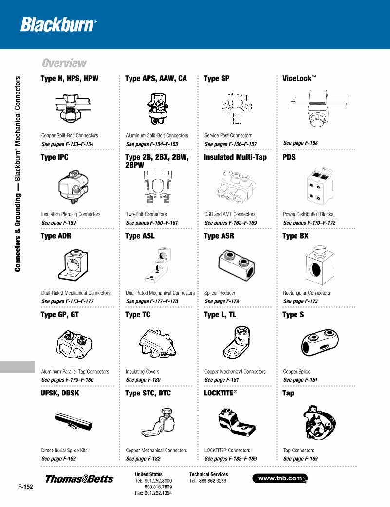
Overview
Conn
ecto
rs &
Gro
undi
ng —
Bla
ckbu
rn® M
echa
nica
l Con
nect
ors Type H, HPS, HPW
Copper Split-Bolt Connectors
See pages F-153–F-154
Type APS, AAW, CA
Aluminum Split-Bolt Connectors
See pages F-154–F-155
Type SP
Service Post Connectors
See pages F-156–F-157
ViceLock™
See page F-158
Type IPC
Insulation Piercing Connectors
See page F-159
Type 2B, 2BX, 2BW, 2BPW
Two-Bolt Connectors
See pages F-160–F-161
Insulated Multi-Tap
CSB and AMT Connectors
See pages F-162–F-169
PDS
Power Distribution Blocks
See pages F-170–F-172
Copper Mechanical Connectors
See page F-181
Type S
Copper Splice
See page F-181
Type STC, BTC
Copper Mechanical Connectors
See page F-182
UFSK, DBSK
Direct-Burial Splice Kits
See page F-182
Type ADR
Dual-Rated Mechanical Connectors
See pages F-173–F-177
Type ASL
Dual-Rated Mechanical Connectors
See pages F-177–F-178
Type ASR
Splicer Reducer
See page F-179
Type BX
Rectangular Connectors
See page F-179
Type GP, GT
Aluminum Parallel Tap Connectors
See pages F-179–F-180
Type TC
Insulating Covers
See page F-180
LOCKTITE®
LOCKTITE® Connectors
See pages F-183–F-189
Tap Connectors
See page F-189
Tap
Type L, TL
United StatesTel: 901.252.8000 800.816.7809Fax: 901.252.1354
Technical ServicesTel: 888.862.3289www.tnb.com
F-153
Connectors & Grounding —
Blackburn® M
echanical Connectors
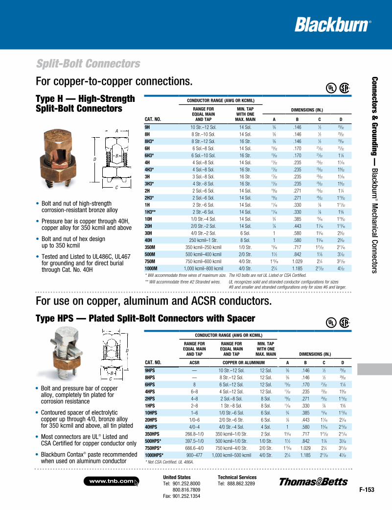
Split-Bolt ConnectorsFor copper-to-copper connections.Type H — High-Strength Split-Bolt Connectors
• Bolt and nut of high-strength corrosion-resistant bronze alloy
• Pressure bar is copper through 40H, copper alloy for 350 kcmil and above
• Bolt and nut of hex design up to 350 kcmil
• Tested and Listed to UL486C, UL467 for grounding and for direct burial through Cat. No. 40H
ConduCtor range (aWg or kCmil)
dimensions (in.)
Cat. no.
range For equal main
and tap
min. tap With one
max. main a B C d
9h 10 Str.–12 Sol. 14 Sol. 3⁄8 .146 1⁄2 25⁄32
8h 8 Str.–10 Sol. 14 Sol. 3⁄8 .146 1⁄2 25⁄32
8h3* 8 Str.–12 Sol. 16 Str. 3⁄8 .146 1⁄2 29⁄32
6h 6 Sol.–8 Sol. 14 Sol. 15⁄32 .170 21⁄3231⁄32
6h3* 6 Sol.–10 Sol. 16 Str. 15⁄32 .170 21⁄32 11⁄84h 4 Sol.–8 Sol. 14 Sol. 17⁄32 .235 23⁄32 11⁄16
4h3* 4 Sol.–8 Sol. 16 Str. 17⁄32 .235 23⁄32 19⁄32
3h 3 Sol.–8 Sol. 16 Str. 17⁄32 .235 23⁄32 11⁄16
3h3* 4 Str.–8 Sol. 16 Str. 17⁄32 .235 23⁄32 19⁄32
2h 2 Sol.–6 Sol. 14 Sol. 19⁄32 .271 25⁄32 11⁄42h3* 2 Sol.–6 Sol. 14 Sol. 19⁄32 .271 25⁄32 115⁄32
1h 2 Str.–6 Sol. 14 Sol. 11⁄16 .330 7⁄8 111⁄32
1h3** 2 Str.–6 Sol. 14 Sol. 11⁄16 .330 7⁄8 15⁄810h 1/0 Str.–4 Sol. 14 Sol. 3⁄4 .385 15⁄16 119⁄32
20h 2/0 Str.–2 Sol. 14 Sol. 7⁄8 .443 11⁄16 113⁄16
30h 4/0 Str.–2 Sol. 6 Sol. 1 .580 15⁄16 25⁄32
40h 250 kcmil–1 Str. 8 Sol. 1 .580 15⁄16 25⁄32
350m 350 kcmil–250 kcmil 1/0 Str. 15⁄16 .717 121⁄32 211⁄16
500m 500 kcmil–400 kcmil 2/0 Str. 11⁄2 .842 17⁄8 31⁄32
750m 750 kcmil–600 kcmil 4/0 Str. 115⁄16 1.029 21⁄4 321⁄32
1000m 1,000 kcmil–800 kcmil 4/0 Str. 21⁄4 1.185 217⁄32 41⁄32
* Will accommodate three wires of maximum size. The H3 bolts are not UL Listed or CSA Certified.** Will accommodate three #2 Stranded wires. UL recognizes solid and stranded conductor configurations for sizes
#8 and smaller and stranded configurations only for sizes #6 and larger.
• Bolt and pressure bar of copper alloy, completely tin plated for corrosion resistance
• Contoured spacer of electrolytic copper up through 4/0, bronze alloy for 350 kcmil and above, all tin plated
• Most connectors are UL® Listed and CSA Certified for copper conductor only
• Blackburn Contax® paste recommended when used on aluminum conductor
For use on copper, aluminum and ACSR conductors.Type HPS — Plated Split-Bolt Connectors with Spacer
Cat. no.
ConduCtor range (aWg or kCmil)
range For equal main
and tap
range For equal main
and tap
min. tap With one
max. main dimensions (in.)
aCsr Copper or aluminum a B C d
9hps — 10 Str.–12 Sol. 12 Sol. 3⁄8 .146 1⁄2 29⁄32
8hps — 8 Str.–12 Sol. 12 Sol. 3⁄8 .146 1⁄2 29⁄32
6hps 8 6 Sol.–12 Sol. 12 Sol. 15⁄32 .170 21⁄32 11⁄84hps 6–8 4 Sol.–12 Sol. 12 Sol. 17⁄32 .235 23⁄32 19⁄32
2hps 4–8 2 Sol.–8 Sol. 8 Sol. 19⁄32 .271 25⁄32 115⁄32
1hps 2–8 1 Str.–8 Sol. 8 Sol. 11⁄16 .330 7⁄8 15⁄810hps 1–6 1/0 Str.–6 Sol. 6 Sol. 3⁄4 .385 15⁄16 113⁄16
20hps 1/0–6 2/0 Str.–6 Str. 6 Sol. 7⁄8 .443 11⁄16 21⁄16
40hps 4/0–4 4/0 Str.–4 Sol. 4 Sol. 1 .580 15⁄16 215⁄32
350hps 266.8–1/0 350 kcmil–1/0 Str. 2 Sol. 15⁄16 .717 121⁄32 211⁄16
500hps* 397.5–1/0 500 kcmil–1/0 Str. 1/0 Str. 11⁄2 .842 17⁄8 31⁄32
750hps* 666.6–4/0 750 kcmil–4/0 Str. 2/0 Str. 115⁄16 1.029 21⁄4 321⁄32
1000hps* 900–477 1,000 kcmil–500 kcmil 4/0 Str. 21⁄4 1.185 217⁄32 41⁄32
* Not CSA Certified. UL 486A.
B
A
C
D
B
D
C
www.tnb.comUnited StatesTel: 901.252.8000 800.816.7809Fax: 901.252.1354
Technical ServicesTel: 888.862.3289
F-154
Split-Bolt Connectors
Conn
ecto
rs &
Gro
undi
ng —
Bla
ckbu
rn® M
echa
nica
l Con
nect
ors
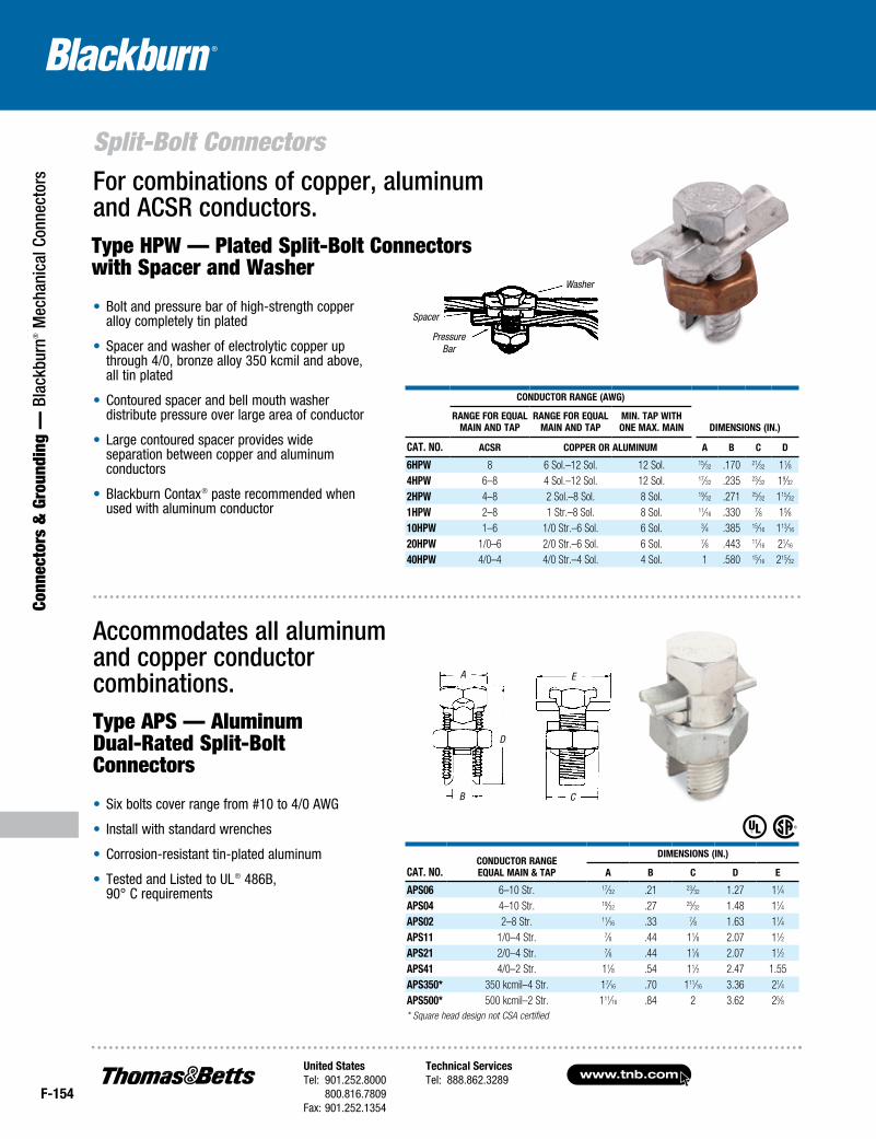
Type HPW — Plated Split-Bolt Connectors with Spacer and Washer
For combinations of copper, aluminum and ACSR conductors.
• Bolt and pressure bar of high-strength copper alloy completely tin plated
• Spacer and washer of electrolytic copper up through 4/0, bronze alloy 350 kcmil and above, all tin plated
• Contoured spacer and bell mouth washer distribute pressure over large area of conductor
• Large contoured spacer provides wide separation between copper and aluminum conductors
• Blackburn Contax® paste recommended when used with aluminum conductor
Type APS — Aluminum Dual-Rated Split-Bolt Connectors
• Six bolts cover range from #10 to 4/0 AWG
• Install with standard wrenches
• Corrosion-resistant tin-plated aluminum
• Tested and Listed to UL® 486B, 90° C requirements
Accommodates all aluminum and copper conductor combinations.
Cat. No.CoNduCtor raNge equal MaiN & tap
diMeNsioNs (iN.)
a B C d e
aps06 6–10 Str. 17⁄32 .21 23⁄32 1.27 11⁄4aps04 4–10 Str. 19⁄32 .27 25⁄32 1.48 11⁄4aps02 2–8 Str. 11⁄16 .33 7⁄8 1.63 11⁄4aps11 1/0–4 Str. 7⁄8 .44 11⁄8 2.07 11⁄2aps21 2/0–4 Str. 7⁄8 .44 11⁄8 2.07 11⁄2aps41 4/0–2 Str. 11⁄8 .54 11⁄2 2.47 1.55aps350* 350 kcmil–4 Str. 17⁄16 .70 111⁄16 3.36 21⁄4aps500* 500 kcmil–2 Str. 111⁄16 .84 2 3.62 25⁄8* Square head design not CSA certified
CoNduCtor raNge (aWg)
diMeNsioNs (iN.)raNge For equal
MaiN aNd tapraNge For equal
MaiN aNd tapMiN. tap With oNe Max. MaiN
Cat. No. aCsr Copper or aluMiNuM a B C d
6hpW 8 6 Sol.–12 Sol. 12 Sol. 15⁄32 .170 21⁄32 11⁄84hpW 6–8 4 Sol.–12 Sol. 12 Sol. 17⁄32 .235 23⁄32 19⁄32
2hpW 4–8 2 Sol.–8 Sol. 8 Sol. 19⁄32 .271 25⁄32 115⁄32
1hpW 2–8 1 Str.–8 Sol. 8 Sol. 11⁄16 .330 7⁄8 15⁄810hpW 1–6 1/0 Str.–6 Sol. 6 Sol. 3⁄4 .385 15⁄16 113⁄16
20hpW 1/0–6 2/0 Str.–6 Sol. 6 Sol. 7⁄8 .443 11⁄16 21⁄16
40hpW 4/0–4 4/0 Str.–4 Sol. 4 Sol. 1 .580 15⁄16 215⁄32
Washer
Spacer
Pressure Bar
A
D
B
E
C
United StatesTel: 901.252.8000 800.816.7809Fax: 901.252.1354
Technical ServicesTel: 888.862.3289www.tnb.com
F-155
Connectors & Grounding —
Blackburn® M
echanical Connectors
Split-Bolt Connectors
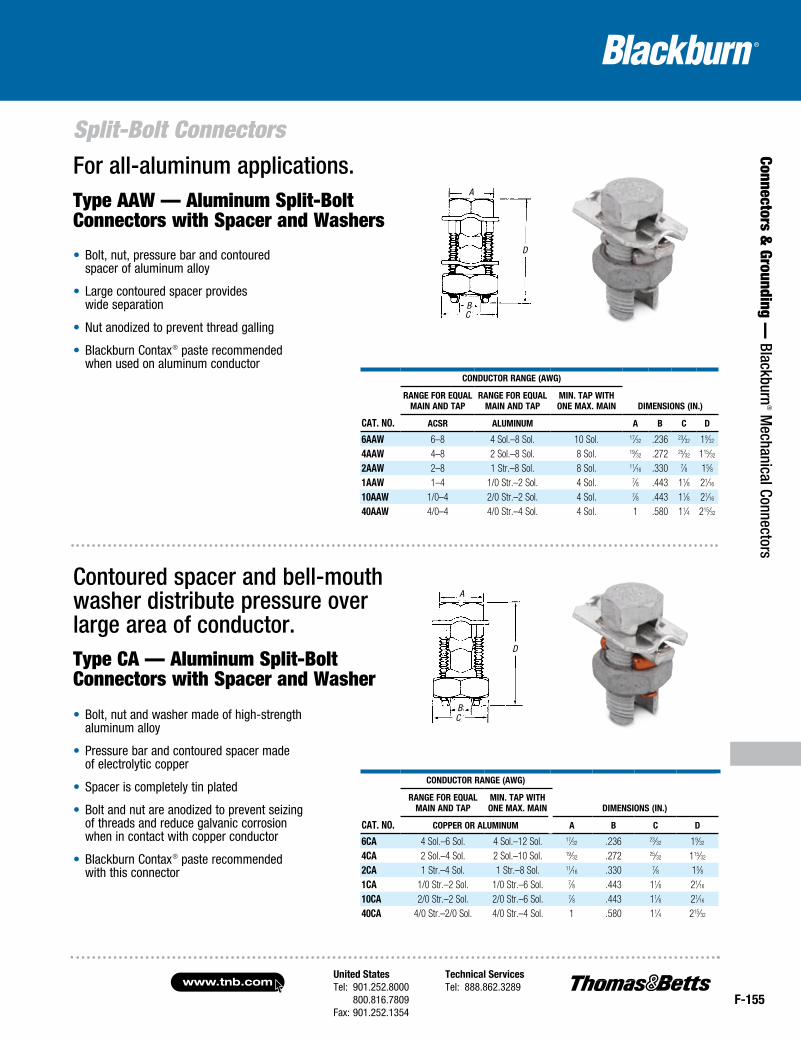
Type AAW — Aluminum Split-Bolt Connectors with Spacer and Washers
• Bolt, nut, pressure bar and contoured spacer of aluminum alloy
• Large contoured spacer provides wide separation
• Nut anodized to prevent thread galling
• Blackburn Contax® paste recommended when used on aluminum conductor
For all-aluminum applications.
Cat. No.
CoNduCtor raNge (aWg)
diMeNsioNs (iN.)raNge For equal
MaiN aNd tapraNge For equal
MaiN aNd tapMiN. tap With oNe Max. MaiN
aCsr aluMiNuM a B C d
6aaW 6–8 4 Sol.–8 Sol. 10 Sol. 17⁄32 .236 23⁄32 19⁄32
4aaW 4–8 2 Sol.–8 Sol. 8 Sol. 19⁄32 .272 25⁄32 115⁄32
2aaW 2–8 1 Str.–8 Sol. 8 Sol. 11⁄16 .330 7⁄8 15⁄81aaW 1–4 1/0 Str.–2 Sol. 4 Sol. 7⁄8 .443 11⁄8 21⁄16
10aaW 1/0–4 2/0 Str.–2 Sol. 4 Sol. 7⁄8 .443 11⁄8 21⁄16
40aaW 4/0–4 4/0 Str.–4 Sol. 4 Sol. 1 .580 11⁄4 215⁄32
Type CA — Aluminum Split-Bolt Connectors with Spacer and Washer
• Bolt, nut and washer made of high-strength aluminum alloy
• Pressure bar and contoured spacer made of electrolytic copper
• Spacer is completely tin plated
• Bolt and nut are anodized to prevent seizing of threads and reduce galvanic corrosion when in contact with copper conductor
• Blackburn Contax® paste recommended with this connector
Contoured spacer and bell-mouth washer distribute pressure over large area of conductor.
Cat. No.
CoNduCtor raNge (aWg)
raNge For equal MaiN aNd tap
MiN. tap With oNe Max. MaiN diMeNsioNs (iN.)
Copper or aluMiNuM a B C d
6Ca 4 Sol.–6 Sol. 4 Sol.–12 Sol. 17⁄32 .236 23⁄32 19⁄32
4Ca 2 Sol.–4 Sol. 2 Sol.–10 Sol. 19⁄32 .272 25⁄32 115⁄32
2Ca 1 Str.–4 Sol. 1 Str.–8 Sol. 11⁄16 .330 7⁄8 15⁄81Ca 1/0 Str.–2 Sol. 1/0 Str.–6 Sol. 7⁄8 .443 11⁄8 21⁄16
10Ca 2/0 Str.–2 Sol. 2/0 Str.–6 Sol. 7⁄8 .443 11⁄8 21⁄16
40Ca 4/0 Str.–2/0 Sol. 4/0 Str.–4 Sol. 1 .580 11⁄4 215⁄32
A
D
BC
BC
D
A
www.tnb.comUnited StatesTel: 901.252.8000 800.816.7809Fax: 901.252.1354
Technical ServicesTel: 888.862.3289
F-156
Service Post Connectors
Conn
ecto
rs &
Gro
undi
ng —
Bla
ckbu
rn® M
echa
nica
l Con
nect
ors
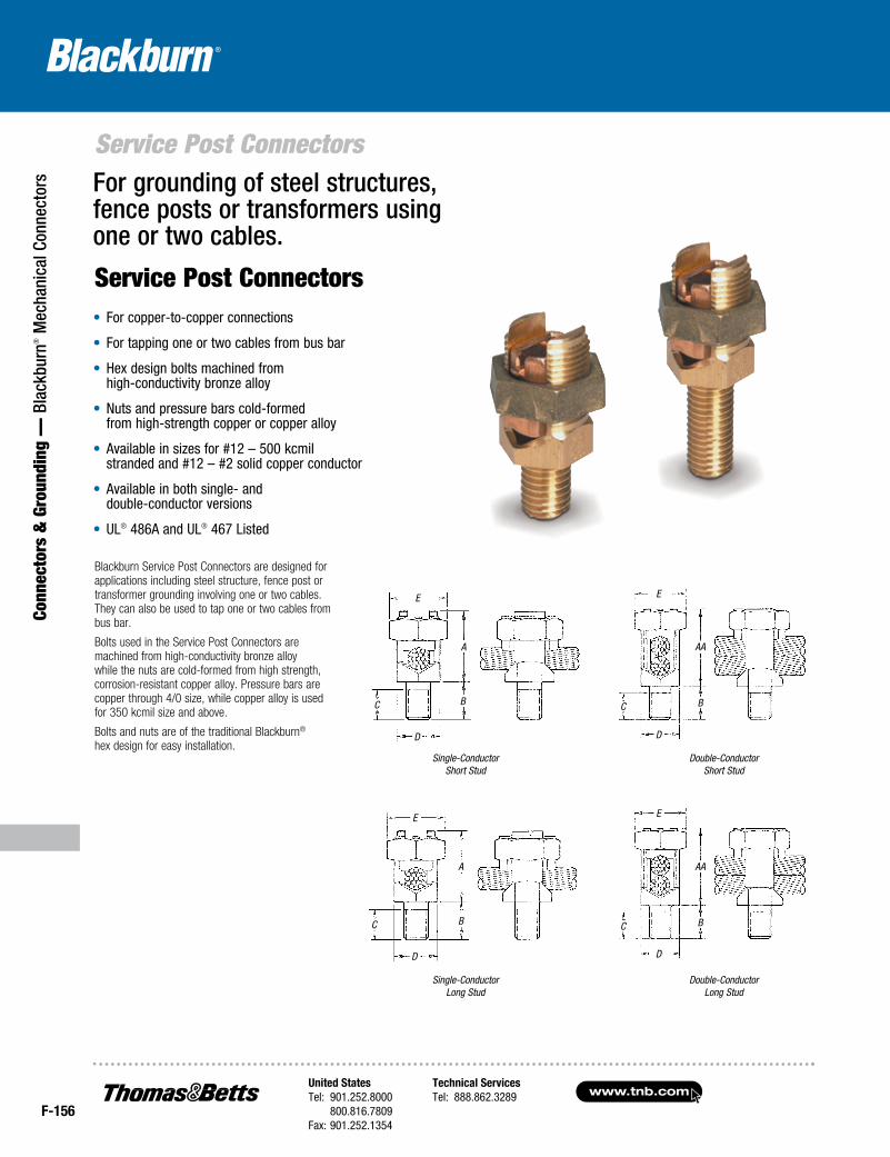
Single-ConductorShort Stud
Double-ConductorShort Stud
Single-ConductorLong Stud
Double-ConductorLong Stud
Blackburn Service Post Connectors are designed for applications including steel structure, fence post or transformer grounding involving one or two cables. They can also be used to tap one or two cables from bus bar.
Bolts used in the Service Post Connectors are machined from high-conductivity bronze alloy while the nuts are cold-formed from high strength, corrosion-resistant copper alloy. Pressure bars are copper through 4/0 size, while copper alloy is used for 350 kcmil size and above.
Bolts and nuts are of the traditional Blackburn® hex design for easy installation.
Service Post Connectors
For grounding of steel structures, fence posts or transformers using one or two cables.
• For copper-to-copper connections
• For tapping one or two cables from bus bar
• Hex design bolts machined from high-conductivity bronze alloy
• Nuts and pressure bars cold-formed from high-strength copper or copper alloy
• Available in sizes for #12 – 500 kcmil stranded and #12 – #2 solid copper conductor
• Available in both single- and double-conductor versions
• UL® 486A and UL® 467 Listed
B
A
E
C
D
AA
E
BC
D
AA
E
BC
D
B
A
E
C
D
United StatesTel: 901.252.8000 800.816.7809Fax: 901.252.1354
Technical ServicesTel: 888.862.3289www.tnb.com
F-157
Connectors & Grounding —
Blackburn® M
echanical Connectors
Service Post ConnectorsSingle- and Double-Conductor Service Post Connectors, Short Stud
Cat. No.
CoNDuCtor raNgeaWgmm2
Diameter raNge (iN.) StuD Size
DimeNSioNS (iN.)StraNDeD SoliDSP-DS SP-SS max. miN. max. miN. a aa B C D e
SP0DS SP0SS8
6mm2
12 8 12 .146–.0811⁄4–20 x 1⁄2 11⁄16
13⁄161⁄2 55⁄64
15⁄321⁄2
4mm2 10mm2 4mm2 —
SP1DS SP1SS7
10mm2
10 6 10 .164–.1021⁄4–20 x 1⁄2 13⁄16
31⁄321⁄2 55⁄64
15⁄3221⁄32
6mm2 10mm2 6mm2 —
SP2DS SP2SS5
16mm2
10 4 10 .206–.1025⁄16–18 x 5⁄8 15⁄16 11⁄8 5⁄8 53⁄64
17⁄3223⁄32
6mm2 — — —
SP3DS SP3SS3
25mm2
10 2 10 .26–.1023⁄8–16 x 5⁄8 1⁄2 11⁄4 5⁄8 61⁄64
5⁄8 25⁄326mm2 — — —
SP4DS SP4SS1
35mm2
8 2 8 .332–.1293⁄8–16 x 5⁄8 11⁄16 13⁄8 5⁄8 61⁄64
11⁄167⁄8
10mm2 — — —
SP5DS SP5SS1/0
50mm2
2 1/0 2 .373–.2581⁄2–13 x 3⁄4 11⁄4 119⁄32
3⁄4 15⁄643⁄4 15⁄16
35mm2 — — —
SP6DS SP6SS2/0
50mm2
2 2/0 2 .419–.2581⁄2–13 x 3⁄4 113⁄32 113⁄16
3⁄4 15⁄647⁄8 11⁄16
35mm2 — — —
SP8DS SP8SS4/0
95mm2
2 4/0 1 .528–.2895⁄8–11 x 1 19⁄16 21⁄16 1 119⁄64 1 15⁄16
35mm2 — — —
SP9DS SP9SS350
150mm2
1/0 — — .681–.3735⁄8–11 x 1 2 23⁄4 11⁄4 119⁄64 15⁄16 111⁄16
50mm2 — — —
SP10DS SP10SS500
240mm2
3/0 — — .814–.473⁄4–10 x 11⁄4 21⁄4 31⁄8 13⁄4 131⁄64 11⁄2 17⁄8
95mm2 — — —
Single- and Double-Conductor Service Post Connectors, long Stud
Cat No.
CoNDuCtor raNgeaWgmm2
Diameter raNge (iN.) StuD Size
DimeNSioNS (iN.)StraNDeD SoliDSP-Sl SP-Dl max. miN. max. miN. a aa B C D e
SP0Sl SP0Dl8
6mm2
12 8 12 .146–.0811⁄4–20 x 1 11⁄16
13⁄16 1 55⁄6415⁄32
1⁄24mm2 10mm2 4mm2 —
SP1Sl SP1Dl7
10mm2
10 6 10 .164–.1021⁄4–20 x 1 13⁄16
31⁄32 1 55⁄6415⁄32
21⁄326mm2 10mm2 6mm2 —
SP2Sl SP2Dl5
16mm2
10 4 10 .206–.1025⁄16–18 x 1 15⁄16 11⁄8 1 53⁄64
17⁄3223⁄32
6mm2 — — —
SP3Sl SP3Dl3
25mm2
10 2 10 .26–.1023⁄8–16 x 11⁄8 1 11⁄4 11⁄8 61⁄64
5⁄8 25⁄326mm2 — — —
SP4Sl SP4Dl1
35mm2
8 2 8 .332–.1293⁄8–16 x 11⁄8 11⁄16 13⁄8 11⁄8 61⁄64
11⁄167⁄8
10mm2 — — —
SP5Sl SP5Dl1/0
50mm2
2 1/0 2 .373–.2581⁄2–13 x 11⁄4 11⁄4 119⁄32 11⁄4 15⁄64
3⁄4 15⁄1635mm2 — — —
SP6Sl SP6Dl2/0
50mm2
2 2/0 2 .419–.258 1⁄2–13 x 11⁄4113⁄32 113⁄16 11⁄4 15⁄64
7⁄8 11⁄1635mm2 — — —
SP8Sl SP8Dl4/0
95mm2
2 4/0 1 .528–.289 5⁄8–11 x 11⁄219⁄16 21⁄16 11⁄2 119⁄64 1 15⁄16
35mm2 — — —
SP9Sl SP9Dl350
150mm2
1/0 — — .681–.3735⁄8–11 x 11⁄2 2 23⁄4 11⁄2 119⁄64 15⁄16 111⁄16
50mm2 — — —
SP10Sl SP10Dl500
240mm2
3/0 — — .814–.473⁄4–10 x 13⁄4 21⁄4 31⁄8 11⁄2 131⁄64 11⁄2 17⁄8
95mm2 — — —
www.tnb.comUnited StatesTel: 901.252.8000 800.816.7809Fax: 901.252.1354
Technical ServicesTel: 888.862.3289
F-158
Parallel Groove Connectors
Conn
ecto
rs &
Gro
undi
ng —
Bla
ckbu
rn® M
echa
nica
l Con
nect
ors
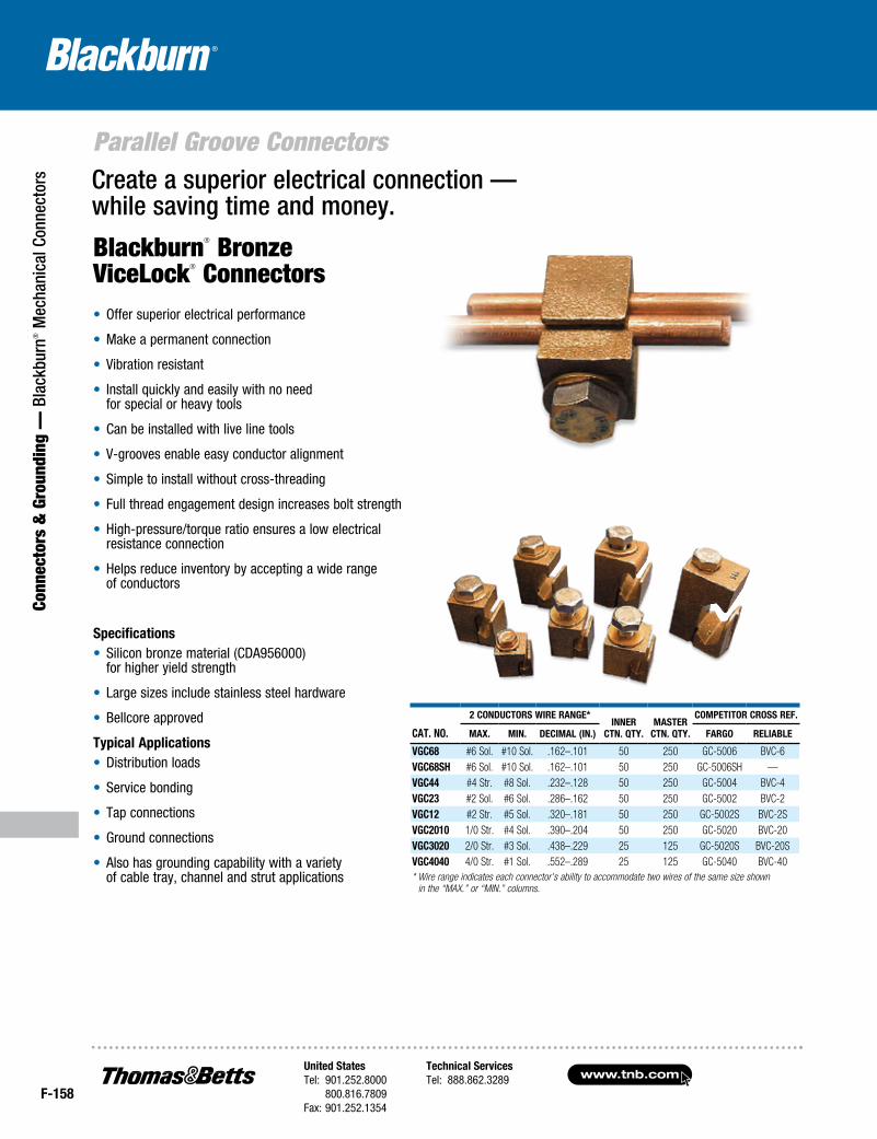
Blackburn® Bronze ViceLock® Connectors• Offer superior electrical performance
• Make a permanent connection
• Vibration resistant
• Install quickly and easily with no need for special or heavy tools
• Can be installed with live line tools
• V-grooves enable easy conductor alignment
• Simple to install without cross-threading
• Full thread engagement design increases bolt strength
• High-pressure/torque ratio ensures a low electrical resistance connection
• Helps reduce inventory by accepting a wide range of conductors
Specifications• Silicon bronze material (CDA956000)
for higher yield strength
• Large sizes include stainless steel hardware
• Bellcore approved
Typical Applications• Distribution loads
• Service bonding
• Tap connections
• Ground connections
• Also has grounding capability with a variety of cable tray, channel and strut applications
Create a superior electrical connection — while saving time and money.
CAT. No.
2 CoNduCTorS Wire rANge* iNNer
CTN. QTy.MASTer
CTN. QTy.
CoMpeTiTor CroSS reF.
MAx. MiN. deCiMAl (iN.) FArgo reliABle
VgC68 #6 Sol. #10 Sol. .162–.101 50 250 GC-5006 BVC-6VgC68SH #6 Sol. #10 Sol. .162–.101 50 250 GC-5006SH —VgC44 #4 Str. #8 Sol. .232–.128 50 250 GC-5004 BVC-4VgC23 #2 Sol. #6 Sol. .286–.162 50 250 GC-5002 BVC-2VgC12 #2 Str. #5 Sol. .320–.181 50 250 GC-5002S BVC-2SVgC2010 1/0 Str. #4 Sol. .390–.204 50 250 GC-5020 BVC-20VgC3020 2/0 Str. #3 Sol. .438–.229 25 125 GC-5020S BVC-20SVgC4040 4/0 Str. #1 Sol. .552–.289 25 125 GC-5040 BVC-40* Wire range indicates each connector’s ability to accommodate two wires of the same size shown in the “MAX.” or “MIN.” columns.
United StatesTel: 901.252.8000 800.816.7809Fax: 901.252.1354
Technical ServicesTel: 888.862.3289www.tnb.com
F-159
Connectors & Grounding —
Blackburn® M
echanical Connectors
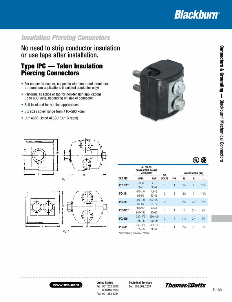
Insulation Piercing ConnectorsNo need to strip conductor insulation or use tape after installation.
Type IPC — Talon Insulation Piercing Connectors• For copper-to-copper, copper-to-aluminum and aluminum-
to-aluminum applications (insulated conductor only)
• Performs as splice or tap for non-tension applications up to 600 volts, depending on size of connector
• Self insulated for hot line applications
• Six sizes cover range from #10–500 kcmil
• UL® 486B Listed AL9CU (90° C rated)
Fig. 1
Fig. 2
CAT. No.
Al or CuCoNduCTor rANge
AWg/MM2
No. BolTS Fig.
diMeNSioNS (iN.)
MAiN TAp W H l
ipC1102*1/0–8 2–8
1 1 29⁄16 2 117⁄3250–6 35–6
ipC41114/0–1/0 1/0–6
2 2 21⁄2 3 119⁄3295–50 50–16
ipC41414/0–1/0 4/0–1/0
2 2 25⁄8 31⁄4 129⁄3295–50 95–50
ipC5041*500–350 4/0–4
1 1 2 21⁄2 21⁄8240–185 90–25
ipC3535350–4/0 350–4/0
2 2 21⁄16 21⁄2 21⁄8185–95 185–95
ipC3541350–4/0 4/0–10
1 1 23⁄4 3 25⁄8185–95 95–6
* 600V Rating (all others 300V).
L
W
H
L
W
H
www.tnb.comUnited StatesTel: 901.252.8000 800.816.7809Fax: 901.252.1354
Technical ServicesTel: 888.862.3289
F-160
Two-Bolt Connectors
Conn
ecto
rs &
Gro
undi
ng —
Bla
ckbu
rn® M
echa
nica
l Con
nect
ors
Cat. No.
CoNduCtor raNge (aWg or kCmil)CoNduCtor
diameter (B)Bolt Head
dimeNsioNs (iN.)maiN tap
max. miN. max. miN. max. miN. l H d
2B10 1/0 Str. 2 Str. 1/0 Str. 10 Sol. .746 .394 1⁄2 15⁄16 13⁄4 5⁄16
2B20BB 2/0 Str. 2 Str. 2/0 Str. 8 Sol. .838 .420 1⁄2 15⁄16 11⁄4 5⁄16
2B40 4/0 Str. 1/0 Str. 4/0 Str. 6 Sol. 1.056 .530 9⁄16 123⁄32 13⁄4 3⁄82B350 350 kcmil 4/0 Str. 350 kcmil 4 Sol. 1.362 .726 3⁄4 21⁄8 2 1⁄22B500 500 kcmil 350 kcmil 500 kcmil 4 Sol. 1.626 .883 3⁄4 21⁄4 21⁄2 1⁄22B800 800 kcmil 600 kcmil 800 kcmil 2 Sol. 2.062 1.149 3⁄4 21⁄2 21⁄2 1⁄22B1000 1000 kcmil 750 kcmil 1000 kcmil 2 Sol. 2.304 1.255 15⁄16 231⁄32 23⁄4 5⁄8UL 486A
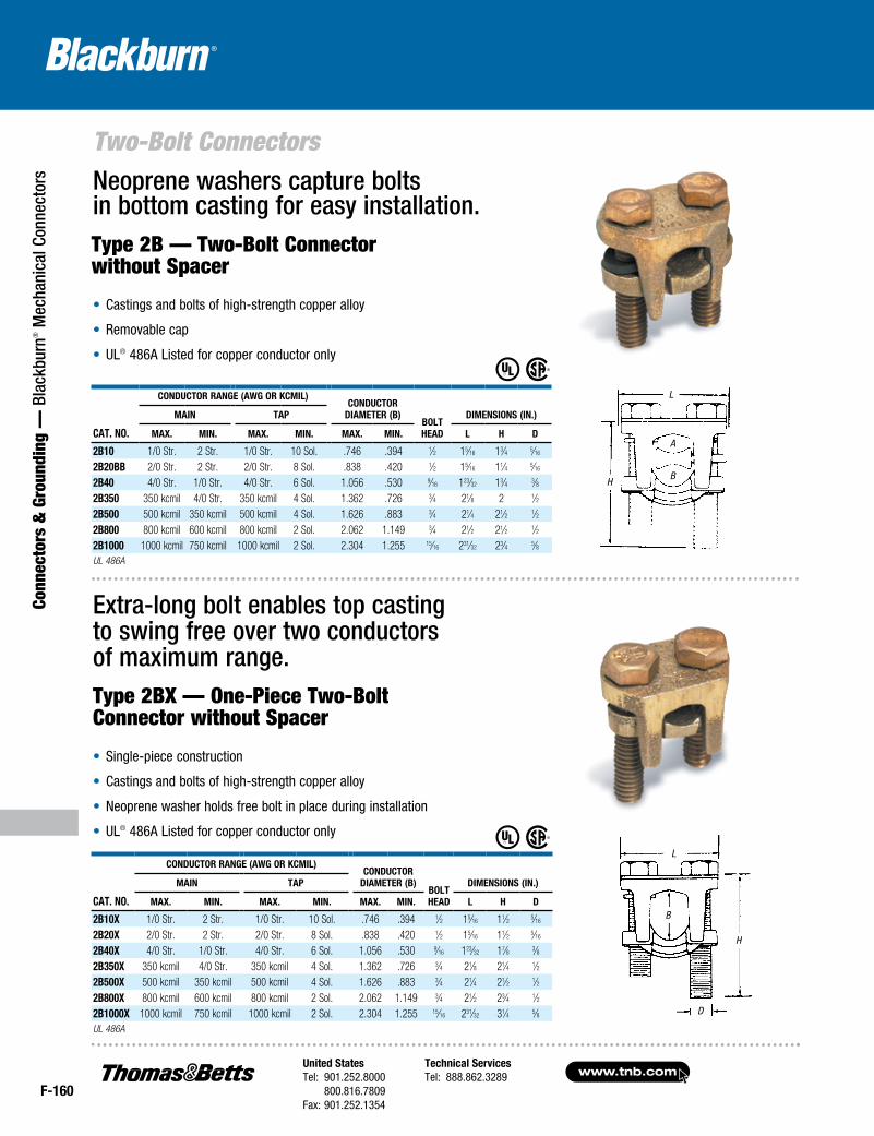
• Single-piece construction
• Castings and bolts of high-strength copper alloy
• Neoprene washer holds free bolt in place during installation
• UL® 486A Listed for copper conductor only
Neoprene washers capture bolts in bottom casting for easy installation.
Extra-long bolt enables top casting to swing free over two conductors of maximum range.Type 2BX — One-Piece Two-Bolt Connector without Spacer
• Castings and bolts of high-strength copper alloy
• Removable cap
• UL® 486A Listed for copper conductor only
Type 2B — Two-Bolt Connector without Spacer
Cat. No.
CoNduCtor raNge (aWg or kCmil)CoNduCtor
diameter (B)Bolt Head
dimeNsioNs (iN.)maiN tap
max. miN. max. miN. max. miN. l H d
2B10x 1/0 Str. 2 Str. 1/0 Str. 10 Sol. .746 .394 1⁄2 15⁄16 11⁄2 5⁄16
2B20x 2/0 Str. 2 Str. 2/0 Str. 8 Sol. .838 .420 1⁄2 15⁄16 11⁄2 5⁄16
2B40x 4/0 Str. 1/0 Str. 4/0 Str. 6 Sol. 1.056 .530 9⁄16 123⁄32 17⁄8 3⁄82B350x 350 kcmil 4/0 Str. 350 kcmil 4 Sol. 1.362 .726 3⁄4 21⁄8 21⁄4 1⁄22B500x 500 kcmil 350 kcmil 500 kcmil 4 Sol. 1.626 .883 3⁄4 21⁄4 21⁄2 1⁄22B800x 800 kcmil 600 kcmil 800 kcmil 2 Sol. 2.062 1.149 3⁄4 21⁄2 23⁄4 1⁄22B1000x 1000 kcmil 750 kcmil 1000 kcmil 2 Sol. 2.304 1.255 15⁄16 231⁄32 31⁄4 5⁄8UL 486A
L
H
A
B
L
B
H
D
United StatesTel: 901.252.8000 800.816.7809Fax: 901.252.1354
Technical ServicesTel: 888.862.3289www.tnb.com
F-161
Connectors & Grounding —
Blackburn® M
echanical Connectors
Two-Bolt Connectors
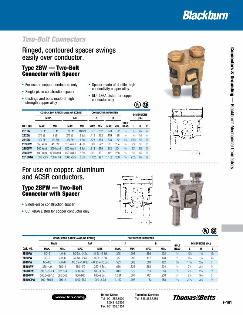
• For use on copper conductors only
• Single-piece construction spacer
• Castings and bolts made of high-strength copper alloy
• Spacer made of ductile, high-conductivity copper alloy
• UL® 486A Listed for copper conductor only
Ringed, contoured spacer swings easily over conductor.Type 2BW — Two-Bolt Connector with Spacer
For use on copper, aluminum and ACSR conductors.Type 2BPW — Two-Bolt Connector with Spacer
• Single-piece construction spacer
• UL® 486A Listed for copper conductor only
Cat. No.
CoNduCtor raNge (aWg or kCmil) CoNduCtor diameter
BoltHead
dimeNsioNs (iN.)maiN tap a B
max. miN. max. miN. max. miN. max. miN. l H e
2B10W 1/0 Str. 2 Str. 1/0 Str. 10 Sol. .373 .292 .373 .102 1⁄2 15⁄16 15⁄8 5⁄16
2B20W 2/0 Str. 2 Str. 2/0 Str. 8 Sol. .419 .292 .419 .128 1⁄2 15⁄16 15⁄8 5⁄16
2B40W 4/0 Str. 1/0 Str. 4/0 Str. 6 Sol. .528 .368 .528 .162 9⁄16 123⁄32 21⁄8 3⁄82B350W 350 kcmil 4/0 Str. 350 kcmil 4 Sol. .681 .522 .681 .204 3⁄4 21⁄8 21⁄2 1⁄22B500W 500 kcmil 350 kcmil 500 kcmil 4 Sol. .813 .679 .813 .204 3⁄4 21⁄4 23⁄4 1⁄22B800W 800 kcmil 600 kcmil 800 kcmil 2 Sol. 1.031 .891 1.031 .258 3⁄4 21⁄2 31⁄4 1⁄22B1000W 1000 kcmil 750 kcmil 1000 kcmil 2 Sol. 1.152 .997 1.152 .258 15⁄16 231⁄32 33⁄4 5⁄8
Cat. No.
CoNduCtor raNge (aWg or kCmil) CoNduCtor diameter
BoltHead
dimeNsioNs (iN.)maiN tap a B
max. miN. max. miN. max. miN. max. miN. l H e
2B10pW 1/0–2 1/0–6 1/0 Str.–2 Str. 1/0 Str.–2 Sol. .398 .292 .398 .102 1⁄2 15⁄16 15⁄8 5⁄16
2B20pW 2/0–2 2/0–6 2/0 Str.–2 Str. 1/0 Str.–2 Sol. .447 .292 .447 .128 1⁄2 15⁄16 15⁄8 5⁄16
2B40pW 4/0–1/0 4/0–6 4/0 Str.–1/0 Str. 4/0 Str.–1/0 Sol. .563 .368 .563 .162 9⁄16 123⁄32 21⁄8 3⁄82B350pW 350–4/0 350–4 350–4/0 350–4 Sol. .680 .522 .680 .204 3⁄4 21⁄8 21⁄2 1⁄22B500pW 397.5–336.4 397.5–4 500–350 500–4 Sol. .813 .679 .813 .204 3⁄4 21⁄4 23⁄4 1⁄22B800pW 666.6–397.5 666.6–2 800–600 800–2 Sol. 1.031 .891 1.031 .258 3⁄4 21⁄2 31⁄4 1⁄22B1000pW 900–666.6 900–2 1000–750 1000–2 Sol. 1.162 .997 1.162 .258 15⁄16 231⁄32 33⁄4 5⁄8
A
B
L
H
A
B
L
H
E
E
www.tnb.comUnited StatesTel: 901.252.8000 800.816.7809Fax: 901.252.1354
Technical ServicesTel: 888.862.3289
F-162
Insulated Multi-Taps
Conn
ecto
rs &
Gro
undi
ng —
Bla
ckbu
rn® M
echa
nica
l Con
nect
ors
cat. no. no. oF outlets wire range screw size
dimensions (in.)
length width height
Splicescsr 2/0 2 #14–2/0
3⁄8 Hex
23⁄4 7⁄8 13⁄8csr 250 2 #6–250 41⁄8 11⁄8 21⁄8csr 350 2 #6–350 43⁄4 13⁄8 21⁄2csr 500 2 2/0–500 61⁄2 15⁄8 27⁄8Cable BlockscsB 4-2 s 2
#4–#14 Slotted
11⁄8
15⁄8 15⁄16
csB 4-3 s 3 19⁄16
csB 4-4 sah* 4 21⁄16
csB 4-5 s 5 29⁄16
csB 4-6 s 6 31⁄16
csB 4-7 s 7 39⁄16
csB 4-8 sah* 8 41⁄16
csB 2/0-2 s 2
2/0–#14 3⁄16 Hex
15⁄8
13⁄4 13⁄8
csB 2/0-3 s 3 23⁄8csB 2/0-4 s 4 31⁄8csB 2/0-5 s 5 37⁄8csB 2/0-6 s 6 45⁄8csB 2/0-7 s 7 53⁄8csB 2/0-8 s 8 61⁄8csB 250-2 s 2
250–#6 5⁄16 Hex
17⁄8
25⁄8 21⁄8
csB 250-3 s 3 227⁄32
csB 250-4 s 4 313⁄16
csB 250-5 s 5 425⁄32
csB 250-6 s 6 53⁄4csB 250-7-s 7 63⁄4csB 250-8 s 8 745⁄64
csB 350-2 s 2
350–#10 5⁄16 Hex
21⁄4
31⁄8 21⁄2
csB 350-3 s 3 31⁄4csB 350-4 s 4 41⁄4csB 350-5 s 5 51⁄4csB 350-6 s 6 61⁄4csB 350-7 s 7 71⁄4csB 350-8 s 8 81⁄4csB 500-2 s 2
500-#6 5⁄16 Hex
27⁄8
33⁄16 23⁄4
csB 500-3 s 3 41⁄8csB 500-4 s 4 53⁄8csB 500-5 s 5 65⁄8csB 500-6 s 6 77⁄8csB 500-7 s 7 91⁄8csB 500-8 s 8 103⁄8* Not UL Listed, includes hex screw.
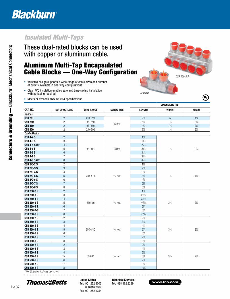
These dual-rated blocks can be used with copper or aluminum cable.
Aluminum Multi-Tap Encapsulated Cable Blocks — One-Way Configuration• Versatile design supports a wide range of cable sizes and number
of outlets available in one-way configurations
• Clear PVC insulation enables safe and time-saving installation with no taping required
• Meets or exceeds ANSI C119.4 specifications
CSB 250-5 S
CSR 2/0
United StatesTel: 901.252.8000 800.816.7809Fax: 901.252.1354
Technical ServicesTel: 888.862.3289www.tnb.com
F-163
Connectors & Grounding —
Blackburn® M
echanical Connectors
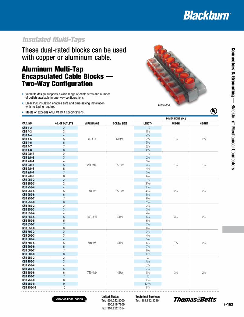
Insulated Multi-TapsThese dual-rated blocks can be used with copper or aluminum cable.
Aluminum Multi-Tap Encapsulated Cable Blocks — Two-Way Configuration
cat. no. no. oF outlets wire range screw size
dimensions (in.)
length width height
csB 4-2 2
#4–#14 Slotted
11⁄8
15⁄8 15⁄16
csB 4-3 3 19⁄16
csB 4-4 4 21⁄16
csB 4-5 5 29⁄16
csB 4-6 6 31⁄16
csB 4-7 7 39⁄16
csB 4-8 8 41⁄16
csB 2/0-2 2
2/0–#14 3⁄16 Hex
15⁄8
13⁄4 13⁄8
csB 2/0-3 3 23⁄8csB 2/0-4 4 31⁄8csB 2/0-5 5 37⁄8csB 2/0-6 6 45⁄8csB 2/0-7 7 53⁄8csB 2/0-8 8 61⁄8csB 250-2 2
250–#6 5⁄16 Hex
17⁄8
25⁄8 21⁄8
csB 250-3 3 227⁄32
csB 250-4 4 313⁄16
csB 250-5 5 425⁄32
csB 250-6 6 53⁄4csB 250-7 7 63⁄4csB 250-8 8 745⁄64
csB 350-2 2
350–#10 3⁄8 Hex
21⁄4
31⁄8 21⁄2
csB 350-3 3 31⁄4csB 350-4 4 41⁄4csB 350-5 5 51⁄4csB 350-6 6 61⁄4csB 350-7 7 71⁄4csB 350-8 8 81⁄4csB 500-2 2
500–#6 3⁄8 Hex
27⁄8
33⁄16 23⁄4
csB 500-3 3 41⁄8csB 500-4 4 53⁄8csB 500-5 5 65⁄8csB 500-6 6 77⁄8csB 500-7 7 91⁄8csB 500-8 8 103⁄8csB 750-2 2
750–1/0 3⁄8 Hex
3
33⁄8 21⁄4
csB 750-3 3 47⁄16
csB 750-4 4 53⁄16
csB 750-5 5 71⁄4csB 750-6 6 85⁄8csB 750-7 7 10csB 750-8 8 117⁄16
csB 750-9 9 1213⁄16
csB 750-10 10 141⁄4
CSB 500-8
• Versatile design supports a wide range of cable sizes and number of outlets available in one-way configurations
• Clear PVC insulation enables safe and time-saving installation with no taping required
• Meets or exceeds ANSI C119.4 specifications
www.tnb.comUnited StatesTel: 901.252.8000 800.816.7809Fax: 901.252.1354
Technical ServicesTel: 888.862.3289
F-164
Insulated Multi-Taps
Conn
ecto
rs &
Gro
undi
ng —
Bla
ckbu
rn® M
echa
nica
l Con
nect
ors
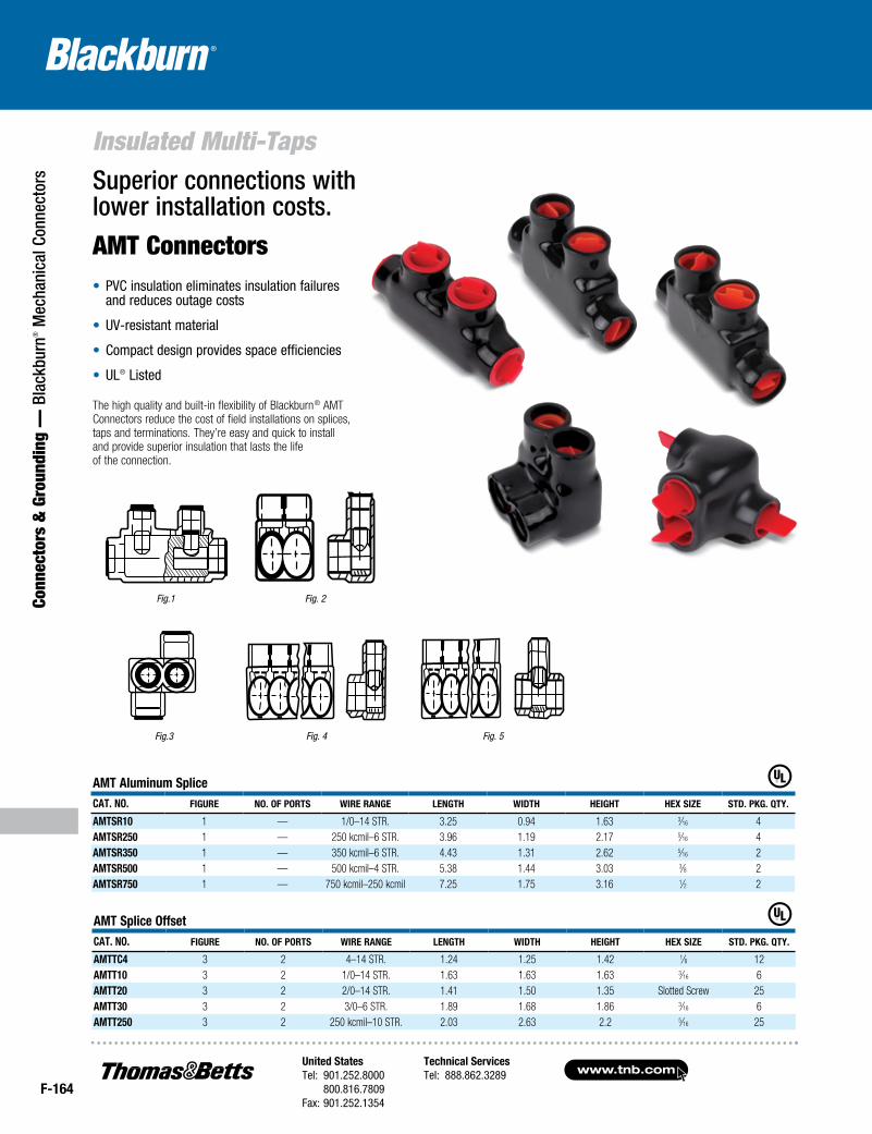
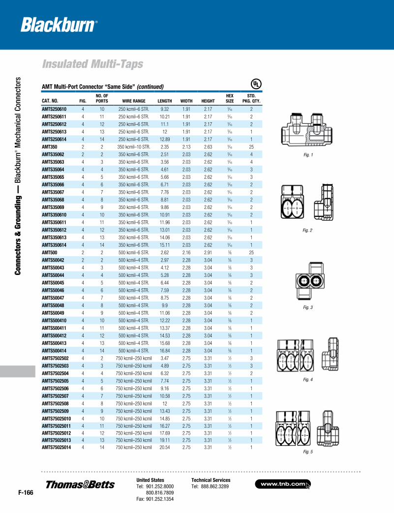
• PVC insulation eliminates insulation failures and reduces outage costs
• UV-resistant material
• Compact design provides space efficiencies
• UL® Listed
The high quality and built-in flexibility of Blackburn® AMT Connectors reduce the cost of field installations on splices, taps and terminations. They’re easy and quick to install and provide superior insulation that lasts the life of the connection.
Superior connections with lower installation costs.
AMT Connectors
Fig.1
Fig.3 Fig. 5
Fig. 2
Fig. 4
AMT Aluminum SpliceCAT. No. Figure No. oF PorTS Wire rANge LeNgTH WiDTH HeigHT HeX SiZe STD. Pkg. qTy.
AMTSr10 1 — 1/0–14 STR. 3.25 0.94 1.63 3⁄16 4AMTSr250 1 — 250 kcmil–6 STR. 3.96 1.19 2.17 5⁄16 4AMTSr350 1 — 350 kcmil–6 STR. 4.43 1.31 2.62 5⁄16 2AMTSr500 1 — 500 kcmil–4 STR. 5.38 1.44 3.03 3⁄8 2AMTSr750 1 — 750 kcmil–250 kcmil 7.25 1.75 3.16 1⁄2 2
AMT Splice offsetCAT. No. Figure No. oF PorTS Wire rANge LeNgTH WiDTH HeigHT HeX SiZe STD. Pkg. qTy.
AMTTC4 3 2 4–14 STR. 1.24 1.25 1.42 1⁄8 12AMTT10 3 2 1/0–14 STR. 1.63 1.63 1.63 3⁄16 6AMTT20 3 2 2/0–14 STR. 1.41 1.50 1.35 Slotted Screw 25AMTT30 3 2 3/0–6 STR. 1.89 1.68 1.86 3⁄16 6AMTT250 3 2 250 kcmil–10 STR. 2.03 2.63 2.2 5⁄16 25
United StatesTel: 901.252.8000 800.816.7809Fax: 901.252.1354
Technical ServicesTel: 888.862.3289www.tnb.com
F-165
Connectors & Grounding —
Blackburn® M
echanical Connectors
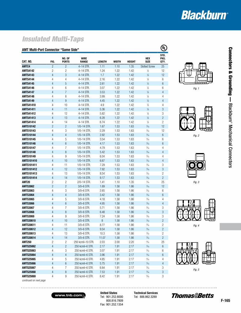
Insulated Multi-TapsAMT Multi-Port Connector “Same Side”
CAT. No. Fig.No. oF PorTS
Wire rANge LeNgTH WiDTH HeigHT
HeX SiZe
STD. Pkg. qTy.
AMTC4 2 2 4–14 STR. 1.11 1.10 1.35 Slotted Screw 25AMTS4142 2 2 4–14 STR. 1.24 1.22 1.42 1⁄8 12AMTS4143 4 3 4–14 STR. 1.7 1.22 1.42 1⁄8 12AMTS4144 4 4 4–14 STR. 2.16 1.22 1.42 1⁄8 6AMTS4145 4 5 4–14 STR. 2.61 1.22 1.42 1⁄8 6AMTS4146 4 6 4–14 STR. 3.07 1.22 1.42 1⁄8 6AMTS4147 4 7 4–14 STR. 3.53 1.22 1.42 1⁄8 4AMTS4148 4 8 4–14 STR. 3.99 1.22 1.42 1⁄8 4AMTS4149 4 9 4–14 STR. 4.45 1.22 1.42 1⁄8 4AMTS41410 4 10 4–14 STR. 4.9 1.22 1.42 1⁄8 4AMTS41411 4 11 4–14 STR. 5.36 1.22 1.42 1⁄8 3AMTS41412 4 12 4–14 STR. 5.82 1.22 1.42 1⁄8 3AMTS41413 4 13 4–14 STR. 6.28 1.22 1.42 1⁄8 2AMTS41414 4 14 4–14 STR. 6.74 1.22 1.42 1⁄8 2AMTS10142 2 2 1/0–14 STR. 1.67 1.53 1.63 3⁄16 12AMTS10143 4 3 1/0–14 STR. 2.29 1.53 1.63 3⁄16 12AMTS10144 4 4 1/0–14 STR. 2.92 1.53 1.63 3⁄16 6AMTS10145 4 5 1/0–14 STR. 3.54 1.53 1.63 3⁄16 6AMTS10146 4 6 1/0–14 STR. 4.17 1.53 1.63 3⁄16 6AMTS10147 4 7 1/0–14 STR. 4.79 1.53 1.63 3⁄16 4AMTS10148 4 8 1/0–14 STR. 5.42 1.53 1.63 3⁄16 4AMTS10149 4 9 1/0–14 STR. 6.04 1.53 1.63 3⁄16 4AMTS101410 4 10 1/0–14 STR. 6.67 1.53 1.63 3⁄16 4AMTS101411 4 11 1/0–14 STR. 7.29 1.53 1.63 3⁄16 3AMTS101412 4 12 1/0–14 STR. 7.92 1.53 1.63 3⁄16 3AMTS101413 4 13 1/0–14 STR. 8.54 1.53 1.63 3⁄16 2AMTS101414 4 14 1/0–14 STR. 9.17 1.53 1.63 3⁄16 2AMT20 2 2 2/0–14 STR. 1.41 1.10 1.35 5⁄16 25AMTS3062 2 2 3/0–6 STR. 1.89 1.58 1.86 3⁄16 12AMTS3063 4 3 3/0–6 STR. 2.65 1.58 1.86 3⁄16 6AMTS3064 4 4 3/0–6 STR. 3.42 1.58 1.86 3⁄16 6AMTS3065 4 5 3/0–6 STR. 4.18 1.58 1.86 3⁄16 4AMTS3066 4 6 3/0–6 STR. 4.95 1.58 1.86 3⁄16 4AMTS3067 4 7 3/0–6 STR. 5.71 1.58 1.86 3⁄16 3AMTS3068 4 8 3/0–6 STR. 6.48 1.58 1.86 3⁄16 3AMTS3069 4 9 3/0–6 STR. 7.24 1.58 1.86 3⁄16 3AMTS30610 4 10 3/0–6 STR. 8 1.58 1.86 3⁄16 2AMTS30611 4 11 3/0–6 STR. 8.77 1.58 1.86 3⁄16 2AMTS30612 4 12 3/0–6 STR. 9.54 1.58 1.86 3⁄16 2AMTS30613 4 13 3/0–6 STR. 10.3 1.58 1.86 3⁄16 2AMTS30614 4 14 3/0–6 STR. 11.07 1.58 1.86 3⁄16 2AMT250 2 2 250 kcmil–10 STR. 2.03 2.00 2.20 5⁄16 25AMTS25062 4 2 250 kcmil–6 STR. 2.17 1.91 2.17 5⁄16 6AMTS25063 4 3 250 kcmil–6 STR. 3.07 1.91 2.17 5⁄16 6AMTS25064 4 4 250 kcmil–6 STR. 3.96 1.91 2.17 5⁄16 6AMTS25065 4 5 250 kcmil–6 STR. 4.85 1.91 2.17 5⁄16 4AMTS25066 4 6 250 kcmil–6 STR. 5.75 1.91 2.17 5⁄16 4AMTS25067 4 7 250 kcmil–6 STR. 6.64 1.91 2.17 5⁄16 3AMTS25068 4 8 250 kcmil–6 STR. 7.53 1.91 2.17 5⁄16 3AMTS25069 4 9 250 kcmil–6 STR. 8.42 1.91 2.17 5⁄16 3continued on next page
Fig. 1
Fig. 3
Fig. 5
Fig. 2
Fig. 4
www.tnb.comUnited StatesTel: 901.252.8000 800.816.7809Fax: 901.252.1354
Technical ServicesTel: 888.862.3289
F-166
Insulated Multi-Taps
Conn
ecto
rs &
Gro
undi
ng —
Bla
ckbu
rn® M
echa
nica
l Con
nect
ors
Fig. 1
Fig. 3
Fig. 5
Fig. 2
Fig. 4
AMT Multi-Port Connector “Same Side” (continued)
CAT. NO. Fig.NO. OFPOrTS wire rANge leNgTh widTh heighT
hexSize
STd.Pkg. qTy.
AMTS250610 4 10 250 kcmil–6 STR. 9.32 1.91 2.17 5⁄16 2
AMTS250611 4 11 250 kcmil–6 STR. 10.21 1.91 2.17 5⁄16 2
AMTS250612 4 12 250 kcmil–6 STR. 11.1 1.91 2.17 5⁄16 2
AMTS250613 4 13 250 kcmil–6 STR. 12 1.91 2.17 5⁄16 1
AMTS250614 4 14 250 kcmil–6 STR. 12.89 1.91 2.17 5⁄16 1
AMT350 2 2 350 kcmil–10 STR. 2.35 2.13 2.63 5⁄16 25
AMTS35062 2 2 350 kcmil–6 STR. 2.51 2.03 2.62 5⁄16 4
AMTS35063 4 3 350 kcmil–6 STR. 3.56 2.03 2.62 5⁄16 4
AMTS35064 4 4 350 kcmil–6 STR. 4.61 2.03 2.62 5⁄16 3
AMTS35065 4 5 350 kcmil–6 STR. 5.66 2.03 2.62 5⁄16 3
AMTS35066 4 6 350 kcmil–6 STR. 6.71 2.03 2.62 5⁄16 2
AMTS35067 4 7 350 kcmil–6 STR. 7.76 2.03 2.62 5⁄16 2
AMTS35068 4 8 350 kcmil–6 STR. 8.81 2.03 2.62 5⁄16 2
AMTS35069 4 9 350 kcmil–6 STR. 9.86 2.03 2.62 5⁄16 2
AMTS350610 4 10 350 kcmil–6 STR. 10.91 2.03 2.62 5⁄16 2
AMTS350611 4 11 350 kcmil–6 STR. 11.96 2.03 2.62 5⁄16 1
AMTS350612 4 12 350 kcmil–6 STR. 13.01 2.03 2.62 5⁄16 1
AMTS350613 4 13 350 kcmil–6 STR. 14.06 2.03 2.62 5⁄16 1
AMTS350614 4 14 350 kcmil–6 STR. 15.11 2.03 2.62 5⁄16 1
AMT500 2 2 500 kcmil–6 STR. 2.62 2.16 2.91 3⁄8 25
AMTS50042 2 2 500 kcmil–4 STR. 2.97 2.28 3.04 3⁄8 3
AMTS50043 4 3 500 kcmil–4 STR. 4.12 2.28 3.04 3⁄8 3
AMTS50044 4 4 500 kcmil–4 STR. 5.28 2.28 3.04 3⁄8 3
AMTS50045 4 5 500 kcmil–4 STR. 6.44 2.28 3.04 3⁄8 2
AMTS50046 4 6 500 kcmil–4 STR. 7.59 2.28 3.04 3⁄8 2
AMTS50047 4 7 500 kcmil–4 STR. 8.75 2.28 3.04 3⁄8 2
AMTS50048 4 8 500 kcmil–4 STR. 9.9 2.28 3.04 3⁄8 2
AMTS50049 4 9 500 kcmil–4 STR. 11.06 2.28 3.04 3⁄8 2
AMTS500410 4 10 500 kcmil–4 STR. 12.22 2.28 3.04 3⁄8 1
AMTS500411 4 11 500 kcmil–4 STR. 13.37 2.28 3.04 3⁄8 1
AMTS500412 4 12 500 kcmil–4 STR. 14.53 2.28 3.04 3⁄8 1
AMTS500413 4 13 500 kcmil–4 STR. 15.68 2.28 3.04 3⁄8 1
AMTS500414 4 14 500 kcmil–4 STR. 16.84 2.28 3.04 3⁄8 1
AMTS7502502 4 2 750 kcmil–250 kcmil 3.47 2.75 3.31 1⁄2 3
AMTS7502503 4 3 750 kcmil–250 kcmil 4.89 2.75 3.31 1⁄2 3
AMTS7502504 4 4 750 kcmil–250 kcmil 6.32 2.75 3.31 1⁄2 2
AMTS7502505 4 5 750 kcmil–250 kcmil 7.74 2.75 3.31 1⁄2 1
AMTS7502506 4 6 750 kcmil–250 kcmil 9.16 2.75 3.31 1⁄2 1
AMTS7502507 4 7 750 kcmil–250 kcmil 10.58 2.75 3.31 1⁄2 1
AMTS7502508 4 8 750 kcmil–250 kcmil 12 2.75 3.31 1⁄2 1
AMTS7502509 4 9 750 kcmil–250 kcmil 13.43 2.75 3.31 1⁄2 1
AMTS75025010 4 10 750 kcmil–250 kcmil 14.85 2.75 3.31 1⁄2 1AMTS75025011 4 11 750 kcmil–250 kcmil 16.27 2.75 3.31 1⁄2 1AMTS75025012 4 12 750 kcmil–250 kcmil 17.69 2.75 3.31 1⁄2 1AMTS75025013 4 13 750 kcmil–250 kcmil 19.11 2.75 3.31 1⁄2 1AMTS75025014 4 14 750 kcmil–250 kcmil 20.54 2.75 3.31 1⁄2 1
United StatesTel: 901.252.8000 800.816.7809Fax: 901.252.1354
Technical ServicesTel: 888.862.3289www.tnb.com
F-167
Connectors & Grounding —
Blackburn® M
echanical Connectors
Insulated Multi-Taps
Fig. 1
Fig. 3
Fig. 5
Fig. 2
Fig. 4
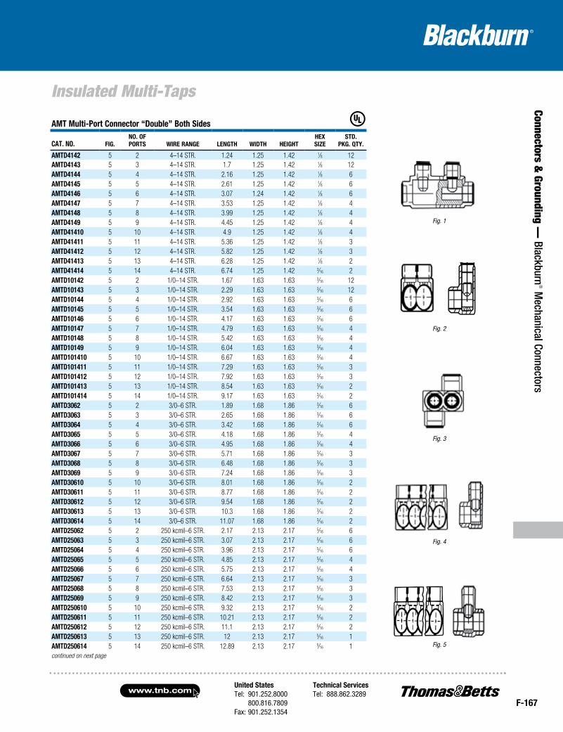
AMT Multi-Port Connector “double” Both Sides
CAT. NO. Fig.NO. OFPOrTS wire rANge leNgTh widTh heighT
hexSize
STd.Pkg. qTy.
AMTd4142 5 2 4–14 STR. 1.24 1.25 1.42 1⁄8 12AMTd4143 5 3 4–14 STR. 1.7 1.25 1.42 1⁄8 12AMTd4144 5 4 4–14 STR. 2.16 1.25 1.42 1⁄8 6AMTd4145 5 5 4–14 STR. 2.61 1.25 1.42 1⁄8 6AMTd4146 5 6 4–14 STR. 3.07 1.24 1.42 1⁄8 6AMTd4147 5 7 4–14 STR. 3.53 1.25 1.42 1⁄8 4AMTd4148 5 8 4–14 STR. 3.99 1.25 1.42 1⁄8 4AMTd4149 5 9 4–14 STR. 4.45 1.25 1.42 1⁄8 4AMTd41410 5 10 4–14 STR. 4.9 1.25 1.42 1⁄8 4AMTd41411 5 11 4–14 STR. 5.36 1.25 1.42 1⁄8 3AMTd41412 5 12 4–14 STR. 5.82 1.25 1.42 1⁄8 3AMTd41413 5 13 4–14 STR. 6.28 1.25 1.42 1⁄8 2AMTd41414 5 14 4–14 STR. 6.74 1.25 1.42 3⁄16 2AMTd10142 5 2 1/0–14 STR. 1.67 1.63 1.63 3⁄16 12AMTd10143 5 3 1/0–14 STR. 2.29 1.63 1.63 3⁄16 12AMTd10144 5 4 1/0–14 STR. 2.92 1.63 1.63 3⁄16 6AMTd10145 5 5 1/0–14 STR. 3.54 1.63 1.63 3⁄16 6AMTd10146 5 6 1/0–14 STR. 4.17 1.63 1.63 3⁄16 6AMTd10147 5 7 1/0–14 STR. 4.79 1.63 1.63 3⁄16 4AMTd10148 5 8 1/0–14 STR. 5.42 1.63 1.63 3⁄16 4AMTd10149 5 9 1/0–14 STR. 6.04 1.63 1.63 3⁄16 4AMTd101410 5 10 1/0–14 STR. 6.67 1.63 1.63 3⁄16 4AMTd101411 5 11 1/0–14 STR. 7.29 1.63 1.63 3⁄16 3AMTd101412 5 12 1/0–14 STR. 7.92 1.63 1.63 3⁄16 3AMTd101413 5 13 1/0–14 STR. 8.54 1.63 1.63 3⁄16 2AMTd101414 5 14 1/0–14 STR. 9.17 1.63 1.63 3⁄16 2AMTd3062 5 2 3/0–6 STR. 1.89 1.68 1.86 3⁄16 6AMTd3063 5 3 3/0–6 STR. 2.65 1.68 1.86 3⁄16 6AMTd3064 5 4 3/0–6 STR. 3.42 1.68 1.86 3⁄16 6AMTd3065 5 5 3/0–6 STR. 4.18 1.68 1.86 3⁄16 4AMTd3066 5 6 3/0–6 STR. 4.95 1.68 1.86 3⁄16 4AMTd3067 5 7 3/0–6 STR. 5.71 1.68 1.86 3⁄16 3AMTd3068 5 8 3/0–6 STR. 6.48 1.68 1.86 3⁄16 3AMTd3069 5 9 3/0–6 STR. 7.24 1.68 1.86 3⁄16 3AMTd30610 5 10 3/0–6 STR. 8.01 1.68 1.86 3⁄16 2AMTd30611 5 11 3/0–6 STR. 8.77 1.68 1.86 3⁄16 2AMTd30612 5 12 3/0–6 STR. 9.54 1.68 1.86 3⁄16 2AMTd30613 5 13 3/0–6 STR. 10.3 1.68 1.86 3⁄16 2AMTd30614 5 14 3/0–6 STR. 11.07 1.68 1.86 3⁄16 2AMTd25062 5 2 250 kcmil–6 STR. 2.17 2.13 2.17 5⁄16 6AMTd25063 5 3 250 kcmil–6 STR. 3.07 2.13 2.17 5⁄16 6AMTd25064 5 4 250 kcmil–6 STR. 3.96 2.13 2.17 5⁄16 6AMTd25065 5 5 250 kcmil–6 STR. 4.85 2.13 2.17 5⁄16 4AMTd25066 5 6 250 kcmil–6 STR. 5.75 2.13 2.17 5⁄16 4AMTd25067 5 7 250 kcmil–6 STR. 6.64 2.13 2.17 5⁄16 3AMTd25068 5 8 250 kcmil–6 STR. 7.53 2.13 2.17 5⁄16 3AMTd25069 5 9 250 kcmil–6 STR. 8.42 2.13 2.17 5⁄16 3AMTd250610 5 10 250 kcmil–6 STR. 9.32 2.13 2.17 5⁄16 2AMTd250611 5 11 250 kcmil–6 STR. 10.21 2.13 2.17 5⁄16 2AMTd250612 5 12 250 kcmil–6 STR. 11.1 2.13 2.17 5⁄16 2AMTd250613 5 13 250 kcmil–6 STR. 12 2.13 2.17 5⁄16 1AMTd250614 5 14 250 kcmil–6 STR. 12.89 2.13 2.17 5⁄16 1continued on next page
www.tnb.comUnited StatesTel: 901.252.8000 800.816.7809Fax: 901.252.1354
Technical ServicesTel: 888.862.3289
F-168
Insulated Multi-Taps
Conn
ecto
rs &
Gro
undi
ng —
Bla
ckbu
rn® M
echa
nica
l Con
nect
ors
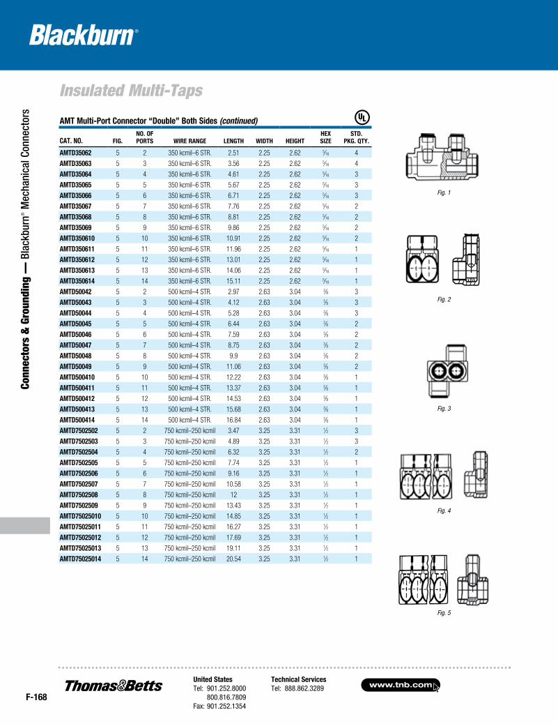
AMT Multi-Port Connector “Double” Both Sides (continued)
CAT. NO. Fig.NO. OFPOrTS wire rANge leNgTh wiDTh heighT
hexSize
STD.Pkg. qTy.
AMTD35062 5 2 350 kcmil–6 STR. 2.51 2.25 2.62 5⁄16 4
AMTD35063 5 3 350 kcmil–6 STR. 3.56 2.25 2.62 5⁄16 4
AMTD35064 5 4 350 kcmil–6 STR. 4.61 2.25 2.62 5⁄16 3
AMTD35065 5 5 350 kcmil–6 STR. 5.67 2.25 2.62 5⁄16 3
AMTD35066 5 6 350 kcmil–6 STR. 6.71 2.25 2.62 5⁄16 3
AMTD35067 5 7 350 kcmil–6 STR. 7.76 2.25 2.62 5⁄16 2
AMTD35068 5 8 350 kcmil–6 STR. 8.81 2.25 2.62 5⁄16 2
AMTD35069 5 9 350 kcmil–6 STR. 9.86 2.25 2.62 5⁄16 2
AMTD350610 5 10 350 kcmil–6 STR. 10.91 2.25 2.62 5⁄16 2
AMTD350611 5 11 350 kcmil–6 STR. 11.96 2.25 2.62 5⁄16 1
AMTD350612 5 12 350 kcmil–6 STR. 13.01 2.25 2.62 5⁄16 1
AMTD350613 5 13 350 kcmil–6 STR. 14.06 2.25 2.62 5⁄16 1
AMTD350614 5 14 350 kcmil–6 STR. 15.11 2.25 2.62 5⁄16 1
AMTD50042 5 2 500 kcmil–4 STR. 2.97 2.63 3.04 3⁄8 3
AMTD50043 5 3 500 kcmil–4 STR. 4.12 2.63 3.04 3⁄8 3
AMTD50044 5 4 500 kcmil–4 STR. 5.28 2.63 3.04 3⁄8 3
AMTD50045 5 5 500 kcmil–4 STR. 6.44 2.63 3.04 3⁄8 2
AMTD50046 5 6 500 kcmil–4 STR. 7.59 2.63 3.04 3⁄8 2
AMTD50047 5 7 500 kcmil–4 STR. 8.75 2.63 3.04 3⁄8 2
AMTD50048 5 8 500 kcmil–4 STR. 9.9 2.63 3.04 3⁄8 2
AMTD50049 5 9 500 kcmil–4 STR. 11.06 2.63 3.04 3⁄8 2
AMTD500410 5 10 500 kcmil–4 STR. 12.22 2.63 3.04 3⁄8 1
AMTD500411 5 11 500 kcmil–4 STR. 13.37 2.63 3.04 3⁄8 1
AMTD500412 5 12 500 kcmil–4 STR. 14.53 2.63 3.04 3⁄8 1
AMTD500413 5 13 500 kcmil–4 STR. 15.68 2.63 3.04 3⁄8 1
AMTD500414 5 14 500 kcmil–4 STR. 16.84 2.63 3.04 3⁄8 1
AMTD7502502 5 2 750 kcmil–250 kcmil 3.47 3.25 3.31 1⁄2 3
AMTD7502503 5 3 750 kcmil–250 kcmil 4.89 3.25 3.31 1⁄2 3
AMTD7502504 5 4 750 kcmil–250 kcmil 6.32 3.25 3.31 1⁄2 2
AMTD7502505 5 5 750 kcmil–250 kcmil 7.74 3.25 3.31 1⁄2 1
AMTD7502506 5 6 750 kcmil–250 kcmil 9.16 3.25 3.31 1⁄2 1
AMTD7502507 5 7 750 kcmil–250 kcmil 10.58 3.25 3.31 1⁄2 1
AMTD7502508 5 8 750 kcmil–250 kcmil 12 3.25 3.31 1⁄2 1
AMTD7502509 5 9 750 kcmil–250 kcmil 13.43 3.25 3.31 1⁄2 1
AMTD75025010 5 10 750 kcmil–250 kcmil 14.85 3.25 3.31 1⁄2 1
AMTD75025011 5 11 750 kcmil–250 kcmil 16.27 3.25 3.31 1⁄2 1
AMTD75025012 5 12 750 kcmil–250 kcmil 17.69 3.25 3.31 1⁄2 1
AMTD75025013 5 13 750 kcmil–250 kcmil 19.11 3.25 3.31 1⁄2 1
AMTD75025014 5 14 750 kcmil–250 kcmil 20.54 3.25 3.31 1⁄2 1
Fig. 1
Fig. 3
Fig. 5
Fig. 2
Fig. 4
United StatesTel: 901.252.8000 800.816.7809Fax: 901.252.1354
Technical ServicesTel: 888.862.3289www.tnb.com
F-169
Connectors & Grounding —
Blackburn® M
echanical Connectors
Insulated Multi-Taps
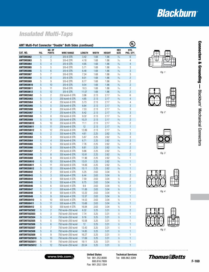
AMT Multi-Port Connector “Double” Both Sides (continued)
CAT. NO. Fig.NO. OFPOrTS wire rANge leNgTh wiDTh heighT
hexSize
STD.Pkg. qTy.
AMTDM3062 5 2 3/0–6 STR. 3.42 1.68 1.86 3⁄16 6AMTDM3063 5 3 3/0–6 STR. 4.18 1.68 1.86 3⁄16 4AMTDM3064 5 4 3/0–6 STR. 4.95 1.68 1.86 3⁄16 4AMTDM3065 5 5 3/0–6 STR. 5.71 1.68 1.86 3⁄16 3AMTDM3066 5 6 3/0–6 STR. 6.48 1.68 1.86 3⁄16 3AMTDM3067 5 7 3/0–6 STR. 7.24 1.68 1.86 3⁄16 3AMTDM3068 5 8 3/0–6 STR. 8.01 1.68 1.86 3⁄16 2AMTDM3069 5 9 3/0–6 STR. 8.77 1.68 1.86 3⁄16 2AMTDM30610 5 10 3/0–6 STR. 9.54 1.68 1.86 3⁄16 2AMTDM30611 5 11 3/0–6 STR. 10.3 1.68 1.86 3⁄16 2AMTDM30612 5 12 3/0–6 STR. 11.07 1.68 1.86 3⁄16 2AMTDM25062 5 2 250 kcmil–6 STR. 3.96 2.13 2.17 5⁄16 6AMTDM25063 5 3 250 kcmil–6 STR. 4.85 2.13 2.17 5⁄16 4AMTDM25064 5 4 250 kcmil–6 STR. 5.73 2.13 2.17 5⁄16 4AMTDM25065 5 5 250 kcmil–6 STR. 6.64 2.13 2.17 5⁄16 3AMTDM25066 5 6 250 kcmil–6 STR. 7.53 2.13 2.17 5⁄16 3AMTDM25067 5 7 250 kcmil–6 STR. 8.42 2.13 2.17 5⁄16 3AMTDM25068 5 8 250 kcmil–6 STR. 9.32 2.13 2.17 5⁄16 2AMTDM25069 5 9 250 kcmil–6 STR. 10.21 2.13 2.17 5⁄16 2AMTDM250610 5 10 250 kcmil–6 STR. 11.1 2.13 2.17 5⁄16 2AMTDM250611 5 11 250 kcmil–6 STR. 12 2.13 2.17 5⁄16 1AMTDM250612 5 12 250 kcmil–6 STR. 12.89 2.13 2.17 5⁄16 1AMTDM35062 5 2 350 kcmil–6 STR. 4.61 2.25 2.62 5⁄16 3AMTDM35063 5 3 350 kcmil–6 STR. 5.67 2.25 2.62 5⁄16 3AMTDM35064 5 4 350 kcmil–6 STR. 6.71 2.25 2.62 5⁄16 3AMTDM35065 5 5 350 kcmil–6 STR. 7.76 2.25 2.62 5⁄16 2AMTDM35066 5 6 350 kcmil–6 STR. 8.81 2.25 2.62 5⁄16 2AMTDM35067 5 7 350 kcmil–6 STR. 9.86 2.25 2.62 5⁄16 2AMTDM35068 5 8 350 kcmil–6 STR. 10.91 2.25 2.62 5⁄16 2AMTDM35069 5 9 350 kcmil–6 STR. 11.96 2.25 2.62 5⁄16 1AMTDM350610 5 10 350 kcmil–6 STR. 13.01 2.25 2.62 5⁄16 1AMTDM350611 5 11 350 kcmil–6 STR. 14.06 2.25 2.62 5⁄16 1AMTDM350612 5 12 350 kcmil–6 STR. 15.11 2.25 2.62 5⁄16 1AMTDM50042 5 2 500 kcmil–4 STR. 5.25 2.63 3.04 3⁄8 3AMTDM50043 5 3 500 kcmil–4 STR. 6.44 2.63 3.04 3⁄8 2AMTDM50044 5 4 500 kcmil–4 STR. 7.59 2.63 3.04 3⁄8 2AMTDM50045 5 5 500 kcmil–4 STR. 8.75 2.63 3.04 3⁄8 2AMTDM50046 5 6 500 kcmil–4 STR. 9.9 2.63 3.04 3⁄8 2AMTDM50047 5 7 500 kcmil–4 STR. 11.06 2.63 3.04 3⁄8 2AMTDM50048 5 8 500 kcmil–4 STR. 12.22 2.63 3.04 3⁄8 1AMTDM50049 5 9 500 kcmil–4 STR. 13.37 2.63 3.04 3⁄8 1AMTDM500410 5 10 500 kcmil–4 STR. 14.53 2.63 3.04 3⁄8 1AMTDM500411 5 11 500 kcmil–4 STR. 15.68 2.63 3.04 3⁄8 1AMTDM500412 5 12 500 kcmil–4 STR. 16.84 2.63 3.04 3⁄8 1AMTDM7502502 5 2 750 kcmil–250 kcmil 6.32 3.25 3.31 1⁄2 2AMTDM7502503 5 3 750 kcmil–250 kcmil 7.74 3.25 3.31 1⁄2 1AMTDM7502504 5 4 750 kcmil–250 kcmil 9.16 3.25 3.31 1⁄2 1AMTDM7502505 5 5 750 kcmil–250 kcmil 10.58 3.25 3.31 1⁄2 1AMTDM7502506 5 6 750 kcmil–250 kcmil 12 3.25 3.31 1⁄2 1AMTDM7502507 5 7 750 kcmil–250 kcmil 13.43 3.25 3.31 1⁄2 1AMTDM7502508 5 8 750 kcmil–250 kcmil 14.85 3.25 3.31 1⁄2 1AMTDM7502509 5 9 750 kcmil–250 kcmil 16.27 3.25 3.31 1⁄2 1AMTDM75025010 5 10 750 kcmil–250 kcmil 17.69 3.25 3.31 1⁄2 1AMTDM75025011 5 11 750 kcmil–250 kcmil 19.11 3.25 3.31 1⁄2 1AMTDM75025012 5 12 750 kcmil–250 kcmil 20.54 3.25 3.31 1⁄2 1
Fig. 1
Fig. 3
Fig. 5
Fig. 2
Fig. 4
www.tnb.comUnited StatesTel: 901.252.8000 800.816.7809Fax: 901.252.1354
Technical ServicesTel: 888.862.3289
F-170
Power Distribution Blocks
Conn
ecto
rs &
Gro
undi
ng —
Bla
ckbu
rn® M
echa
nica
l Con
nect
ors Power Distribution Blocks
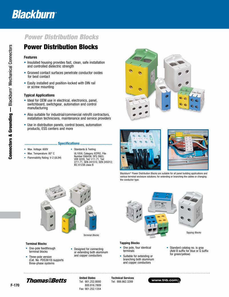
Features• Insulated housing provides fast, clean, safe installation
and controlled dielectric strength
• Grooved contact surfaces penetrate conductor oxides for best contact
• Easily installed and position-locked with DIN rail or screw mounting
Blackburn® Power Distribution Blocks are suitable for all panel building applications and various terminal enclosure solutions; for extending or branching the cables or changing the conductor type.
• Max. Voltage: 600V
• Max. Temperature: 80° C
• Flammability Rating: V-2 (UL94)
• Standards & Testing:
UL1059, Category XCFR2, File Number E66436; SFS 2663; VDE 0220, Teil 1/11.71, Teil 2/11.71, SEN 241510, SEN 245012; IEC 61238 class B
.................................... Specifications ...................................
Tapping BlocksTerminal Blocks
Typical Applications• Ideal for OEM use in electrical, electronics, panel,
switchboard, switchgear, automation and control manufacturing
• Also suitable for industrial/commercial retrofit contractors, installation technicians, maintenance and service providers
• Use in distribution panels, control boxes, automation products, ESS centers and more
Tapping Blocks• One pole, four identical
terminals
• Suitable for extending or branching both aluminum and copper conductors
• Standard catalog no. is gray (Add B suffix for blue or G suffix for green/yellow)
Terminal Blocks• One-pole feedthrough
terminal blocks
• Three-pole version (Cat. No. PDS3610) supports three-phase systems
• Designed for connecting or extending both aluminum and copper conductors
United StatesTel: 901.252.8000 800.816.7809Fax: 901.252.1354
Technical ServicesTel: 888.862.3289www.tnb.com
F-171
Connectors & Grounding —
Blackburn® M
echanical Connectors
Power Distribution Blocks
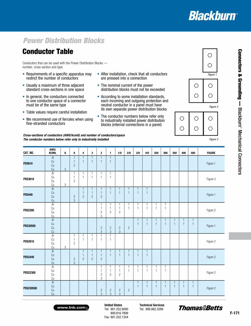
• Requirements of a specific apparatus may restrict the number of conductors
• Usually a maximum of three adjacent standard cross-sections in one space
• In general, the conductors connected to one conductor space of a connector must be of the same type
• Table values require careful installation
• We recommend use of ferrules when using fine-stranded conductors
• After installation, check that all conductors are pressed into a connection
• The nominal current of the power distribution blocks must not be exceeded
• According to some installation standards, each incoming and outgoing protection and neutral conductor in a panel must have its own separate power distribution blocks
• The conductor numbers below refer only to industrially installed power distribution blocks (internal connections in a panel)
Conductor Table
Cross-sections of conductors (AWG/kcmil) and number of conductors/space The conductor numbers below refer only to industrially installed
CAT. NO.Awg/kCmil 8 6 4 3 2 1 1/0 2/0 3/0 4/0 250 300 350 400 500 Figure
PDS610
Al 1 1 1 1 1
Figure 1Cu 1 1 1 1 1Cu 2Cu 3
PDS3610
Al 1 1 1 1 1
Figure 3Cu 1 1 1 1 1Cu 2Cu 3
PDS440
Al 1 1 1 1 1 1 1 1
Figure 1Cu 1 1 1 1 1 1 1 1Cu 2 2 2 2Cu 3
PDS2300
Al 1 1 1 1 1 1 1 1
Figure 2Cu 1 1 1 1 1 1 1 1Cu 2 2 2Cu 3
PDS30500
Al 1 1 1 1 1 1 1
Figure 1Cu 1 1 1 1 1 1 1Cu 2 2 2 2Cu 3 3 3
PDS2610
Al 1 1 1 1 1
Figure 2Cu 1 1 1 1 1Cu 2Cu 3
PDS2440
Al 1 1 1 1 1 1 1 1
Figure 2Cu 1 1 1 1 1 1 1 1Cu 2 2 2 2Cu 3
PDS22300
Al 1 1 1 1 1 1 1 1
Figure 2Cu 1 1 1 1 1 1 1 1Cu 2 2 2Cu 3
PDS230500
Al 1 1 1 1 1 1 1
Figure 2Cu 1 1 1 1 1 1 1Cu 2 2 2 2Cu 3 3 3
Figure 1
Figure 2
Figure 3
Conductors that can be used with the Power Distribution Blocks — number, cross-section and type.
www.tnb.comUnited StatesTel: 901.252.8000 800.816.7809Fax: 901.252.1354
Technical ServicesTel: 888.862.3289
F-172
Power Distribution Blocks
Conn
ecto
rs &
Gro
undi
ng —
Bla
ckbu
rn® M
echa
nica
l Con
nect
ors
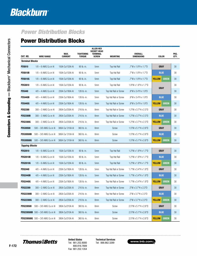
CAT. NO. WIRE RANGEMAX.
CURRENTTIGHTENING
TORQUE
ALLEN HEXSOCKET HEAD
TERMINAL SCREW MOUNTING
OVERALLDIMENSIONS COLOR
PKG.QTY.
Terminal Blocks
PDS610 1/0 – 6 AWG Cu or Al 150A Cu/120A Al 90 lb.-in. 5mm Top Hat Rail .7"W x 1.9"H x 1.7"D GRAY 30
PDS610B 1/0 – 6 AWG Cu or Al 150A Cu/120A Al 90 lb.-in. 5mm Top Hat Rail .7"W x 1.9"H x 1.7"D BLUE 30
PDS610G 1/0 – 6 AWG Cu or Al 150A Cu/120A Al 90 lb.-in. 5mm Top Hat Rail .7"W x 1.9"H x 1.7"D YELLOW GREEN 30
PDS3610 1/0 – 6 AWG Cu or Al 150A Cu/120A Al 90 lb.-in. 5mm Top Hat Rail 1.9"W x 1.9"H x 1.7"DGRAY
30
PDS440 4/0 – 4 AWG Cu or Al 230A Cu/180A Al 126 lb.-in. 5mm Top Hat Rail or Screw .9"W x 3.4"H x 1.9"D 30
PDS440B 4/0 – 4 AWG Cu or Al 230A Cu/180A Al 126 lb.-in. 5mm Top Hat Rail or Screw .9"W x 3.4"H x 1.9"D BLUE 30
PDS440G 4/0 – 4 AWG Cu or Al 230A Cu/180A Al 126 lb.-in. 5mm Top Hat Rail or Screw .9"W x 3.4"H x 1.9"D YELLOW GREEN 30
PDS2300 300 – 2 AWG Cu or Al 285A Cu/230A Al 216 lb.-in. 8mm Top Hat Rail or Screw 1.2"W x 3.7"H x 2.3"D GRAY 30
PDS2300B 300 – 2 AWG Cu or Al 285A Cu/230A Al 216 lb.-in. 8mm Top Hat Rail or Screw 1.2"W x 3.7"H x 2.3"D BLUE 30
PDS2300G 300 – 2 AWG Cu or Al 285A Cu/230A Al 216 lb.-in. 8mm Top Hat Rail or Screw 1.2"W x 3.7"H x 2.3"D YELLOW GREEN 30
PDS30500 500 – 3/0 AWG Cu or Al 380A Cu/ 310A Al 360 lb.-in. 8mm Screw 1.5"W x 5.1"H x 2.6"D GRAY 30
PDS30500B 500 – 3/0 AWG Cu or Al 380A Cu/ 310A Al 360 lb.-in. 8mm Screw 1.5"W x 5.1"H x 2.6"D BLUE 30
PDS30500G 500 – 3/0 AWG Cu or Al 380A Cu/ 310A Al 360 lb.-in. 8mm Screw 1.5"W x 5.1"H x 2.6"D YELLOW GREEN 30
Tapping Blocks
PDS2610 1/0 – 6 AWG Cu or Al 150A Cu/120A Al 90 lb.-in. 5mm Top Hat Rail 1.2"W x 1.9"H x 1.7"D GRAY 30
PDS2610B 1/0 – 6 AWG Cu or Al 150A Cu/120A Al 90 lb.-in. 5mm Top Hat Rail 1.2"W x 1.9"H x 1.7"D BLUE 30
PDS2610G 1/0 – 6 AWG Cu or Al 150A Cu/120A Al 90 lb.-in. 5mm Top Hat Rail 1.2"W x 1.9"H x 1.7"D YELLOW GREEN 30
PDS2440 4/0 – 4 AWG Cu or Al 230A Cu/180A Al 126 lb.-in. 5mm Top Hat Rail or Screw 1.7"W x 3.4"H x 1.9"D GRAY 30
PDS2440B 4/0 – 4 AWG Cu or Al 230A Cu/180A Al 126 lb.-in. 5mm Top Hat Rail or Screw 1.7"W x 3.4"H x 1.9"D BLUE 30
PDS2440G 4/0 – 4 AWG Cu or Al 230A Cu/180A Al 126 lb.-in. 5mm Top Hat Rail or Screw 1.7"W x 3.4"H x 1.9"D YELLOW GREEN 30
PDS22300 300 – 2 AWG Cu or Al 285A Cu/230A Al 216 lb.-in. 8mm Top Hat Rail or Screw 2"W x 3.7"H x 2.3"D GRAY 30
PDS22300B 300 – 2 AWG Cu or Al 285A Cu/230A Al 216 lb.-in. 8mm Top Hat Rail or Screw 2"W x 3.7"H x 2.3"D BLUE 30
PDS22300G 300 – 2 AWG Cu or Al 285A Cu/230A Al 216 lb.-in. 8mm Top Hat Rail or Screw 2"W x 3.7"H x 2.3"D YELLOW GREEN 30
PDS230500 500 – 3/0 AWG Cu or Al 380A Cu/310A Al 360 lb.-in. 8mm Screw 2.5"W x 5.1"H x 2.6"D GRAY 30
PDS230500B 500 – 3/0 AWG Cu or Al 380A Cu/310A Al 360 lb.-in. 8mm Screw 2.5"W x 5.1"H x 2.6"D BLUE 30
PDS230500G 500 – 3/0 AWG Cu or Al 380A Cu/310A Al 360 lb.-in. 8mm Screw 2.5"W x 5.1"H x 2.6"D YELLOW GREEN 30
Power Distribution Blocks
United StatesTel: 901.252.8000 800.816.7809Fax: 901.252.1354
Technical ServicesTel: 888.862.3289www.tnb.com
F-173
Connectors & Grounding —
Blackburn® M
echanical Connectors
Anti-Rotational Connectors
Fig. 1 Fig. 2
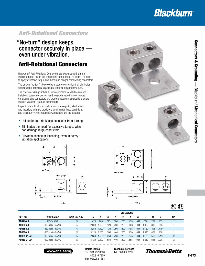
Anti-Rotational ConnectorsBlackburn ® Anti-Rotational Connectors are designed with a rib on the bottom that keeps the connectors from turning, so there’s no need to apply excessive torque and there’s no danger of loosening connectors.
The unique “no-turn” rib provides a secure connection that eliminates the conductor pinching that results from connector movement.
The “no-turn” design solves a unique problem for electricians and installers. Larger conductors tend to get damaged in over-torque conditions, and connectors are prone to loosen in applications where there is vibration, such as motor loads.
Inspectors and local standards boards are requiring electricians and installers to make provisions to eliminate these conditions, and Blackburn ® Anti-Rotational Connectors are the solution.
• Unique bottom rib keeps connector from turning
• Eliminates the need for excessive torque, which can damage large conductors
• Prevents connector loosening, even in heavy-vibration applications
“No-turn” design keeps connector securely in place — even under vibration.
CAT. NO. WIRE RANGE BOLT HOLE (IN.)
DIMENSIONS
FIG. A B C D E F G H M N
ADR21-AR 2/0–14 AWG 1⁄4 1.470 .600 .790 .190 .200 .438 .094 .620 .267 .453 1ADR30-AR 300 kcmil–6 AWG 7⁄16 2.000 1.000 1.120 .250 .200 .468 .094 1.000 .330 .656 1ADR35-AR 350 kcmil–6 AWG 5⁄16 2.250 1.120 1.125 .250 .200 .485 .094 1.120 .408 .719 1ADR60-AR 600 kcmil–2 AWG 1⁄2 3.120 1.500 1.560 .440 .200 .720 .094 1.380 .408 .938 1ADR35-21-AR 350 kcmil–6 AWG 3⁄8 2.880 1.500 1.250 .250 .200 .875 .094 1.120 .563 .719 2ADR60-21-AR 600 kcmil–2 AWG 1⁄2 3.120 2.400 1.560 .440 .200 .555 .094 1.380 .531 .938 2
G E
D
A
M
N
B
F
H
C
G E
D
M
N
B
F
H
C
www.tnb.comUnited StatesTel: 901.252.8000 800.816.7809Fax: 901.252.1354
Technical ServicesTel: 888.862.3289
F-174
Dual-Rated Mechanical Connectors
Conn
ecto
rs &
Gro
undi
ng —
Bla
ckbu
rn® M
echa
nica
l Con
nect
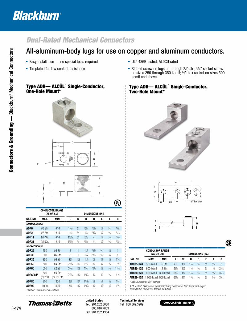
ors All-aluminum-body lugs for use on copper and aluminum conductors.
• Easy installation — no special tools required
• Tin plated for low contact resistance
• UL® 486B tested, AL9CU rated
• Slotted screw on lugs up through 2/0 str.; 5⁄16" socket screw on sizes 250 through 350 kcmil; 3⁄8" hex socket on sizes 500 kcmil and above
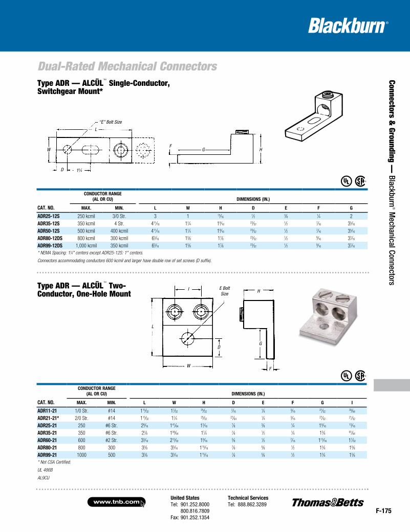
Cat. No.
CoNduCtor raNge(aL or Cu) dimeNsioNs (iN.)
max. miN. L W H d e F g
adr35-12# 350 kcmil 6 Str. 41⁄4 11⁄4 13⁄8 5⁄8 1⁄2 5⁄16 3adr60-12d 600 kcmil 2 Str. 55⁄16 11⁄2 11⁄2 5⁄8 1⁄2 3⁄8 31⁄16
adr80-12d 800 kcmil 300 kcmil 63⁄16 13⁄4 17⁄8 5⁄8 1⁄2 9⁄16 37⁄16
adr99-12d 1,000 kcmil 500 kcmil 63⁄16 13⁄4 17⁄8 5⁄8 1⁄2 9⁄16 37⁄16
* NEMA spacing: 13⁄4" centers
# UL Listed. Connectors accommodating conductors 600 kcmil and larger have double row of set screws (D suffix).
Cat. No.
CoNduCtor raNge (aL or Cu) dimeNsioNs (iN.)
max. miN. L W H d e F g
Slotted Screwadr6 #6 Str. #14 13⁄64
1⁄2 31⁄6415⁄64
1⁄4 5⁄6443⁄64
adr2 #2 Str. #14 15⁄321⁄2 9⁄16
19⁄641⁄4 7⁄64
11⁄16
adr11 1/0 Str. #14 115⁄325⁄8 25⁄32
7⁄161⁄4 3⁄16
27⁄32
adr21 2/0 Str. #14 115⁄325⁄8 25⁄32
7⁄161⁄4 3⁄16
27⁄32
Socket Screwadr25 250 #6 Str. 2 1 11⁄8 15⁄32
5⁄161⁄4 1
adr30 300 #6 Str. 2 1 11⁄8 15⁄325⁄16
1⁄4 1adr35 350 #6 Str. 21⁄4 11⁄8 11⁄4 1⁄2 3⁄8 1⁄4 11⁄8adr50 500 #4 Str. 213⁄16 11⁄2 19⁄16
3⁄4 3⁄8 5⁄16 119⁄32
adr60 600 #2 Str. 33⁄16 11⁄2 19⁄1613⁄16
3⁄8 7⁄16 113⁄16
adr6004*600
(2) 250#4 Str.
(2) 1/0 Str.213⁄16 13⁄8 113⁄16
5⁄8 3⁄8 5⁄16 11⁄2
adr80 800 300 33⁄8 13⁄4 115⁄165⁄8 5⁄8 1⁄2 13⁄4
adr99 1000 500 33⁄8 13⁄4 115⁄165⁄8 5⁄8 1⁄2 13⁄4
* Not UL Listed or CSA Certified.
G HF
“E” Bolt Size
L
W
D 13⁄4
LD
E
F
D
W
H
Type ADR— ALCÜL™ Single-Conductor, Two-Hole Mount*
Type ADR— ALCÜL™ Single-Conductor, One-Hole Mount*
United StatesTel: 901.252.8000 800.816.7809Fax: 901.252.1354
Technical ServicesTel: 888.862.3289www.tnb.com
F-175
Connectors & Grounding —
Blackburn® M
echanical Connectors
Dual-Rated Mechanical Connectors
Cat. No.
CoNduCtor raNge(aL or Cu) dimeNsioNs (iN.)
max. miN. L W H d e F g
adr25-12s 250 kcmil 3/0 Str. 3 1 13⁄161⁄2 3⁄8 1⁄4 2
adr35-12s 350 kcmil 4 Str. 411⁄16 11⁄4 19⁄1623⁄32
1⁄2 7⁄16 35⁄16
adr50-12s 500 kcmil 400 kcmil 411⁄16 11⁄4 19⁄1623⁄32
1⁄2 7⁄16 35⁄16
adr80-12ds 800 kcmil 300 kcmil 63⁄16 15⁄8 17⁄8 23⁄321⁄2 9⁄16 37⁄16
adr99-12ds 1,000 kcmil 350 kcmil 63⁄16 15⁄8 17⁄8 23⁄321⁄2 9⁄16 37⁄16
* NEMA Spacing: 13⁄4" centers except ADR25-12S: 1" centers.
Connectors accommodating conductors 600 kcmil and larger have double row of set screws (D suffix).
“E” Bolt Size
Type ADR — ALCÜL™ Single-Conductor, Switchgear Mount*
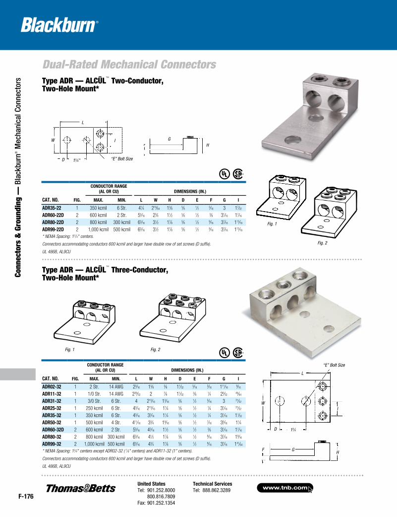
Cat. No.
CoNduCtor raNge (aL or Cu) dimeNsioNs (iN.)
max. miN. L W H d e F g i
adr11-21 1/0 Str. #14 115⁄32 17⁄3225⁄32
7⁄161⁄4 3⁄16
27⁄3235⁄64
adr21-21* 2/0 Str. #14 115⁄32 11⁄4 25⁄3227⁄64
1⁄4 3⁄1627⁄32
21⁄32
adr25-21 250 #6 Str. 29⁄16 141⁄64 13⁄167⁄8 3⁄8 1⁄4 19⁄16
13⁄16
adr35-21 350 #6 Str. 27⁄8 159⁄64 11⁄4 7⁄8 1⁄2 1⁄4 13⁄4 61⁄64
adr60-21 600 #2 Str. 33⁄16 213⁄32 19⁄165⁄8 1⁄2 7⁄16 113⁄16 17⁄32
adr80-21 800 300 33⁄8 33⁄16 115⁄167⁄8 5⁄8 1⁄2 13⁄4 15⁄8
adr99-21 1000 500 33⁄8 33⁄16 115⁄167⁄8 5⁄8 1⁄2 13⁄4 15⁄8
* Not CSA Certified.
U L 486B
AL9CU
Type ADR — ALCÜL™ Two-Conductor, One-Hole Mount
G HF
L
W
D 13⁄4
L
E Bolt Size
D
W
I
G
H
F
www.tnb.comUnited StatesTel: 901.252.8000 800.816.7809Fax: 901.252.1354
Technical ServicesTel: 888.862.3289
F-176
Dual-Rated Mechanical Connectors
Conn
ecto
rs &
Gro
undi
ng —
Bla
ckbu
rn® M
echa
nica
l Con
nect
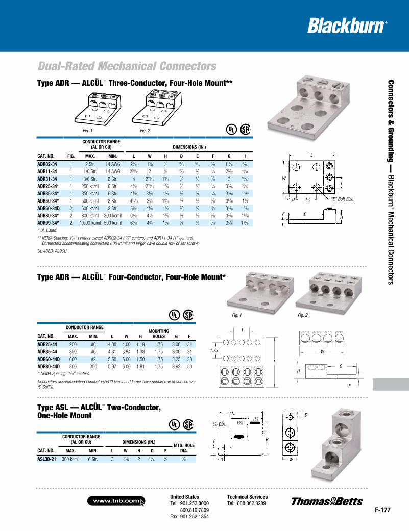
ors Type ADR — ALCÜL™ Two-Conductor,
Two-Hole Mount*
Cat. No. Fig.
CoNduCtor raNge(aL or Cu) dimeNsioNs (iN.)
max. miN. L W H d e F g i
adr35-22 1 350 kcmil 6 Str. 41⁄4 219⁄64 13⁄8 5⁄8 1⁄2 5⁄16 3 17⁄32
adr60-22d 2 600 kcmil 2 Str. 55⁄16 23⁄4 11⁄2 5⁄8 1⁄2 3⁄8 31⁄16 17⁄16
adr80-22d 2 800 kcmil 300 kcmil 63⁄16 31⁄2 17⁄8 5⁄8 1⁄2 9⁄16 37⁄16 113⁄16
adr99-22d 2 1,000 kcmil 500 kcmil 63⁄16 31⁄2 17⁄8 5⁄8 1⁄2 9⁄16 37⁄16 113⁄16
* NEMA Spacing: 13/4" centers.
Connectors accommodating conductors 600 kcmil and larger have double row of set screws (D suffix).
UL 486B, AL9CU
13⁄4D
WI
L
F G H
Cat. No. Fig.
CoNduCtor raNge(aL or Cu) dimeNsioNs (iN.)
max. miN. L W H d e F g i
adr02-32 1 2 Str. 14 AWG 23⁄16 15⁄8 5⁄8 11⁄325⁄16
3⁄16 111⁄169⁄16
adr11-32 1 1/0 Str. 14 AWG 229⁄32 2 7⁄8 11⁄323⁄8 1⁄4 25⁄32
45⁄64
adr31-32 1 3/0 Str. 6 Str. 4 213⁄16 13⁄165⁄8 1⁄2 5⁄16 3 31⁄32
adr25-32 1 250 kcmil 6 Str. 43⁄16 213⁄16 11⁄4 5⁄8 1⁄2 1⁄4 31⁄1631⁄32
adr35-32 1 350 kcmil 6 Str. 43⁄16 33⁄16 11⁄4 5⁄8 1⁄2 1⁄4 31⁄16 11⁄32
adr50-32 1 500 kcmil 4 Str. 411⁄16 33⁄4 19⁄165⁄8 1⁄2 7⁄16 35⁄16 11⁄4
adr60-32d 2 600 kcmil 2 Str. 55⁄16 43⁄16 11⁄2 5⁄8 1⁄2 3⁄8 31⁄16 17⁄16
adr80-32 2 800 kcmil 300 kcmil 63⁄16 41⁄2 17⁄8 5⁄8 1⁄2 9⁄16 37⁄16 19⁄16
adr99-32 2 1,000 kcmil 500 kcmil 63⁄16 43⁄4 17⁄8 5⁄8 1⁄2 9⁄16 37⁄16 141⁄64
* NEMA Spacing: 13⁄4" centers except ADR02-32 ( 7⁄8" centers) and ADR11-32 (1" centers).
Connectors accommodating conductors 600 kcmil and larger have double row of set screws (D suffix).
UL 486B, AL9CU
“E” Bolt Size
Fig. 1 Fig. 2
Type ADR — ALCÜL™ Three-Conductor, Two-Hole Mount*
Fig. 2
Fig. 1
L
I
D
W GH
“E” Bolt Size13⁄4"
United StatesTel: 901.252.8000 800.816.7809Fax: 901.252.1354
Technical ServicesTel: 888.862.3289www.tnb.com
F-177
Connectors & Grounding —
Blackburn® M
echanical Connectors
Dual-Rated Mechanical Connectors
HG
F
Cat. No. Fig.
CoNduCtor raNge(aL or Cu) dimeNsioNs (iN.)
max. miN. L W H d e F g i
adr02-34 1 2 Str. 14 AWG 23⁄16 15⁄8 5⁄8 11⁄325⁄16
3⁄16 111⁄169⁄16
adr11-34 1 1/0 Str. 14 AWG 229⁄32 2 7⁄8 11⁄323⁄8 1⁄4 25⁄32
45⁄64
adr31-34 1 3/0 Str. 6 Str. 4 213⁄16 13⁄165⁄8 1⁄2 5⁄16 3 31⁄32
adr25-34* 1 250 kcmil 6 Str. 43⁄16 213⁄16 11⁄4 5⁄8 1⁄2 1⁄4 31⁄1631⁄32
adr35-34* 1 350 kcmil 6 Str. 43⁄16 33⁄16 11⁄4 5⁄8 1⁄2 1⁄4 31⁄16 11⁄32
adr50-34* 1 500 kcmil 2 Str. 411⁄16 33⁄4 19⁄165⁄8 1⁄2 7⁄16 35⁄16 11⁄4
adr60-34d 2 600 kcmil 2 Str. 55⁄16 43⁄16 11⁄2 5⁄8 1⁄2 3⁄8 31⁄16 17⁄16
adr80-34* 2 800 kcmil 300 kcmil 63⁄16 41⁄2 17⁄8 5⁄8 1⁄2 9⁄16 37⁄16 19⁄16
adr99-34* 2 1,000 kcmil 500 kcmil 63⁄16 43⁄4 17⁄8 5⁄8 1⁄2 9⁄16 37⁄16 141⁄64
* UL Listed.
** NEMA Spacing: 13⁄4" centers except ADR02-34 ( 7⁄8" centers) and ADR11-34 (1" centers). Connectors accommodating conductors 600 kcmil and larger have double row of set screws.
UL 486B, AL9CU
13⁄4 “E” Bolt Size
Cat. No.
CoNduCtor raNge
L W HmouNtiNg
HoLes g Fmax. miN.
adr25-44 250 #6 4.00 4.06 1.19 1.75 3.00 .31adr35-44 350 #6 4.31 3.94 1.38 1.75 3.00 .31adr60-44d 600 #2 5.50 5.00 1.50 1.75 3.25 .38adr80-44d 800 350 5.97 6.00 1.81 1.75 3.63 .50* NEMA Spacing: 13⁄4" centers.
Connectors accommodating conductors 600 kcmil and larger have double row of set screws (D Suffix).
Type ADR — ALCÜL™ Four-Conductor, Four-Hole Mount*
Type ADR — ALCÜL™ Three-Conductor, Four-Hole Mount**
Fig. 1 Fig. 2
I
L
1.75 W
13⁄32 DIA. 13⁄16
13⁄8
HF
D W
D
Cat. No.
CoNduCtor raNge(aL or Cu) dimeNsioNs (iN.)
mtg. HoLe dia.max. miN. L W H d F
asL30-21 300 kcmil 6 Str. 3 11⁄8 2 15⁄321⁄2 5⁄16
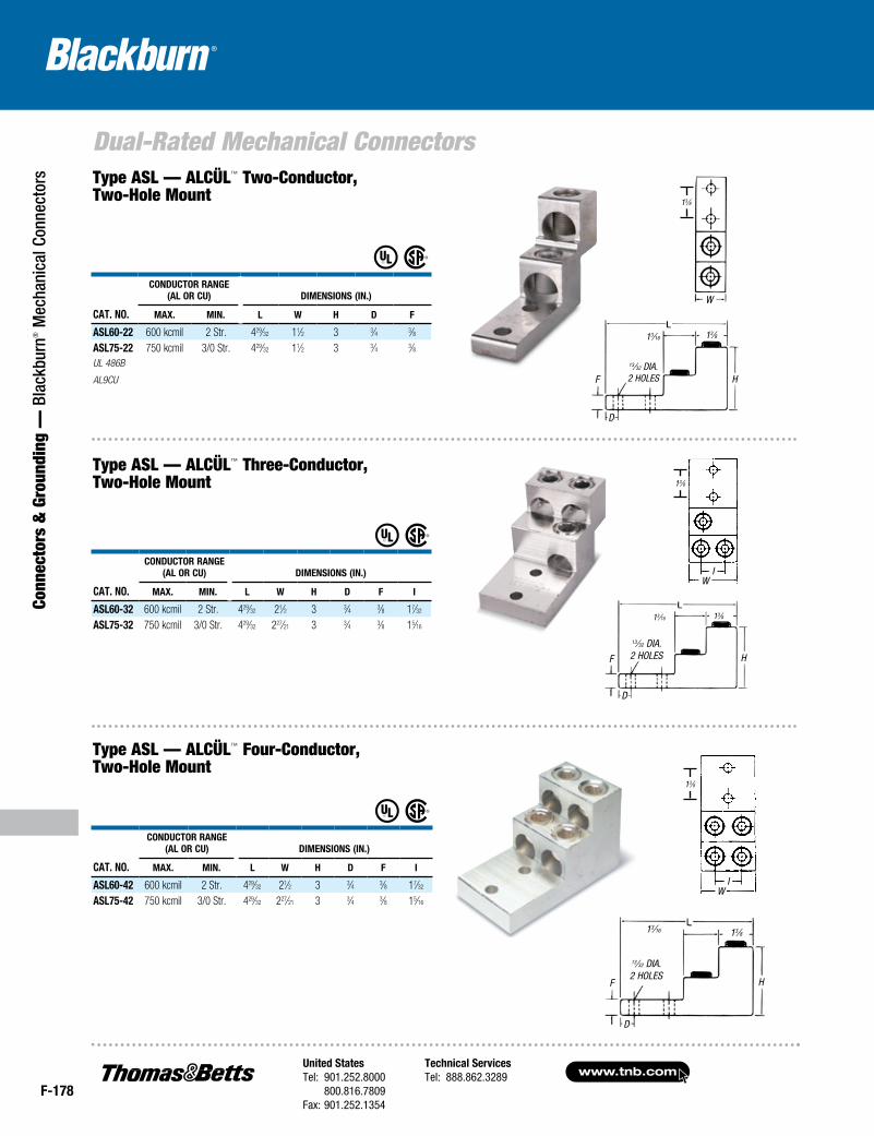
Type ASL — ALCÜL™ Two-Conductor, One-Hole Mount
Fig. 1 Fig. 2
GFH
D
WI
L
www.tnb.comUnited StatesTel: 901.252.8000 800.816.7809Fax: 901.252.1354
Technical ServicesTel: 888.862.3289
F-178
Dual-Rated Mechanical Connectors
Conn
ecto
rs &
Gro
undi
ng —
Bla
ckbu
rn® M
echa
nica
l Con
nect
ors
13⁄32 DIA.2 HOLES
13⁄16 13⁄8
13⁄32 DIA.2 HOLES
13⁄16 13⁄8
13⁄8
Cat. No.
CoNduCtor raNge (aL or Cu) dimeNsioNs (iN.)
max. miN. L W H d F
asL60-22 600 kcmil 2 Str. 429⁄32 11⁄2 3 3⁄4 3⁄8asL75-22 750 kcmil 3/0 Str. 429⁄32 11⁄2 3 3⁄4 3⁄8UL 486B
AL9CU
13⁄16 13⁄8
13⁄32 DIA.2 HOLES
13⁄8
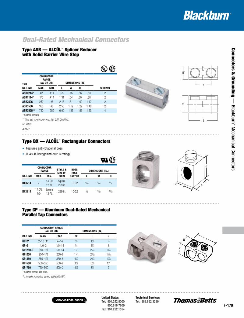
Cat. No.
CoNduCtor raNge (aL or Cu) dimeNsioNs (iN.)
max. miN. L W H d F i
asL60-32 600 kcmil 2 Str. 429⁄32 21⁄2 3 3⁄4 3⁄8 17⁄32
asL75-32 750 kcmil 3/0 Str. 429⁄32 227⁄21 3 3⁄4 3⁄8 15⁄16
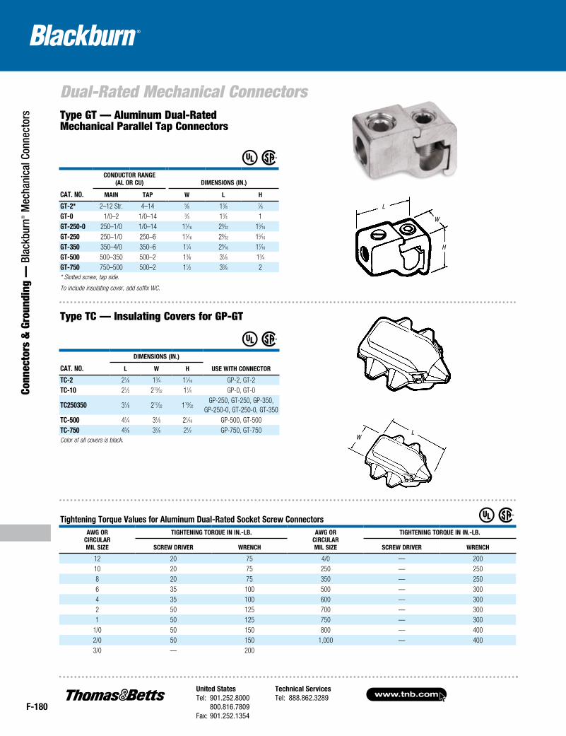
Cat. No.
CoNduCtor raNge (aL or Cu) dimeNsioNs (iN.)
max. miN. L W H d F i
asL60-42 600 kcmil 2 Str. 429⁄32 21⁄2 3 3⁄4 3⁄8 17⁄32
asL75-42 750 kcmil 3/0 Str. 429⁄32 227⁄21 3 3⁄4 3⁄8 15⁄16
13⁄8
Type ASL — ALCÜL™ Two-Conductor, Two-Hole Mount
Type ASL — ALCÜL™ Three-Conductor, Two-Hole Mount
Type ASL — ALCÜL™ Four-Conductor, Two-Hole Mount
W
HF
D
IW
HF
D
IW
HF
D
United StatesTel: 901.252.8000 800.816.7809Fax: 901.252.1354
Technical ServicesTel: 888.862.3289www.tnb.com
F-179
Connectors & Grounding —
Blackburn® M
echanical Connectors
Dual-Rated Mechanical Connectors
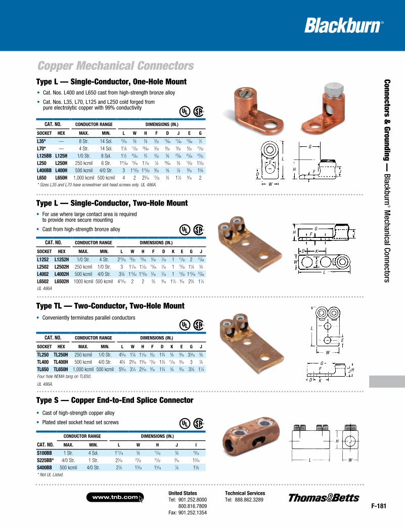
• Features anti-rotational boss
• UL486B Recognized (90° C rating)
Type BX — ALCÜL™ Rectangular Connectors
Cat. No.
CoNduCtor raNge styLe &
size oF Boss
Boss HoLe
tapped
dimeNsioNs (iN.)
max. miN. L W H
Bx0214 214 CU 12 AL
Square .229 in.
10-32 15⁄3215⁄32
9⁄16
Bx111414 CU
1/0Square12 AL
.229 in. 10-32 5⁄8 17⁄3239⁄64
Type GP — Aluminum Dual-Rated Mechanical Parallel Tap Connectors
Cat. No.
CoNduCtor raNge (aL or Cu) dimeNsioNs (iN.)
maiN tap W L H
gp-2* 2–12 Str. 4–14 5⁄8 13⁄8 7⁄8gp-0 1/0–2 1/0–14 3⁄4 13⁄4 1gp-250-0 250–1/0 1/0–14 11⁄16 21⁄32 15⁄16
gp-250 250–1/0 250–6 11⁄16 29⁄32 15⁄16
gp-350 350–4/0 350–6 11⁄4 29⁄16 17⁄16
gp-500 500–350 500–2 13⁄8 31⁄8 13⁄4gp-750 750–500 500–2 11⁄2 33⁄8 2* Slotted screw, tap side.
To include insulating cover, add suffix WC.
Type ASR — ALCÜL™ Splicer Reducer with Solid Barrier Wire Stop
W
L
H
It&B Cat. No.
CoNduCtor raNge
(aL or Cu) dimeNsioNs (iN.)
sCreWsmax. miN. L W H i
asr0214* #2 #14 .95 .45 .56 .53 2asr1114* 1/0 #14 1.31 .54 .60 .68 2asr2506 250 #6 2.18 .81 1.00 1.12 2asr3506 350 #6 2.56 1.12 1.29 1.48 2asr7525** 750 250 6.00 1.53 1.95 1.93 4* Slotted screws
** Two set screws per end. Not CSA Certified.
UL 486B
AL9CU
H
LW
H
W L
www.tnb.comUnited StatesTel: 901.252.8000 800.816.7809Fax: 901.252.1354
Technical ServicesTel: 888.862.3289
F-180
Dual-Rated Mechanical Connectors
Conn
ecto
rs &
Gro
undi
ng —
Bla
ckbu
rn® M
echa
nica
l Con
nect
ors Type GT — Aluminum Dual-Rated
Mechanical Parallel Tap Connectors
Type TC — Insulating Covers for GP-GT
Cat. No.
CoNduCtor raNge (aL or Cu) dimeNsioNs (iN.)
maiN tap W L H
gt-2* 2–12 Str. 4–14 5⁄8 13⁄8 7⁄8gt-0 1/0–2 1/0–14 3⁄4 13⁄4 1gt-250-0 250–1/0 1/0–14 11⁄16 29⁄32 15⁄16
gt-250 250–1/0 250–6 11⁄16 29⁄32 15⁄16
gt-350 350–4/0 350–6 11⁄4 29⁄16 17⁄16
gt-500 500–350 500–2 13⁄8 31⁄8 13⁄4gt-750 750–500 500–2 11⁄2 33⁄8 2* Slotted screw, tap side.
To include insulating cover, add suffix WC.
tightening torque Values for aluminum dual-rated socket screw ConnectorsaWg or
CirCuLar miL size
tigHteNiNg torque iN iN.-Lb. aWg or CirCuLar miL size
tigHteNiNg torque iN iN.-Lb.
sCreW driVer WreNCH sCreW driVer WreNCH
12 20 75 4/0 — 20010 20 75 250 — 2508 20 75 350 — 2506 35 100 500 — 3004 35 100 600 — 3002 50 125 700 — 3001 50 125 750 — 300
1/0 50 150 800 — 4002/0 50 150 1,000 — 4003/0 — 200
Cat. No.
dimeNsioNs (iN.)
use WitH CoNNeCtorL W H
tC-2 21⁄8 13⁄4 11⁄16 GP-2, GT-2tC-10 21⁄2 213⁄32 11⁄4 GP-0, GT-0
tC250350 31⁄8 217⁄32 119⁄32GP-250, GT-250, GP-350,
GP-250-0, GT-250-0, GT-350tC-500 41⁄4 31⁄8 21⁄16 GP-500, GT-500tC-750 45⁄8 37⁄8 21⁄2 GP-750, GT-750Color of all covers is black.
L
W
H
LW
United StatesTel: 901.252.8000 800.816.7809Fax: 901.252.1354
Technical ServicesTel: 888.862.3289www.tnb.com
F-181
Connectors & Grounding —
Blackburn® M
echanical Connectors
Copper Mechanical Connectors
• For use where large contact area is required to provide more secure mounting
• Cast from high-strength bronze alloy
• Cast of high-strength copper alloy
• Plated steel socket head set screws
• Cat. Nos. L400 and L650 cast from high-strength bronze alloy
• Cat. Nos. L35, L70, L125 and L250 cold forged from pure electrolytic copper with 99% conductivity
• Conveniently terminates parallel conductors
Type L — Single-Conductor, One-Hole Mount
Type L — Single-Conductor, Two-Hole Mount
Cat. No. CoNduCtor raNge dimeNsioNs (iN.)
soCket Hex max. miN. L W H F d k e g j
L1252 L1252H 1/0 Str. 4 Str. 213⁄1625⁄32
13⁄163⁄16
7⁄16 1 11⁄32 2 27⁄64
L2502 L2502H 250 kcmil 1/0 Str. 3 11⁄16 11⁄3215⁄64
7⁄16 1 13⁄32 17⁄8 5⁄8L4002 L4002H 500 kcmil 4/0 Str. 33⁄8 113⁄32 115⁄32
5⁄167⁄16 1 13⁄32 115⁄16
57⁄64
L6502 L6502H 1000 kcmil 500 kcmil 415⁄16 2 2 3⁄8 9⁄16 11/29⁄16 23⁄4 11⁄4
UL 486A
Cat. No. CoNduCtor raNge dimeNsioNs (iN.)
soCket Hex max. miN. L W H F d j e g
L35* — 8 Str. 14 Sol. 13⁄163⁄8 3⁄8 3⁄32
13⁄6411⁄64
13⁄641⁄2
L70* — 4 Str. 14 Sol. 11⁄8 17⁄3235⁄64
3⁄329⁄32
9⁄329⁄32
21⁄32
L125bb L125H 1/0 Str. 8 Sol. 11⁄2 47⁄643⁄4 3⁄32
3⁄8 27⁄6421⁄64
27⁄32
L250 L250H 250 kcmil 6 Str. 161⁄6415⁄16 11⁄16
1⁄8 29⁄645⁄8 13⁄32 13⁄32
L400bb L400H 500 kcmil 4/0 Str. 3 113⁄32 115⁄329⁄32
5⁄8 7⁄8 9⁄16 15⁄8L650 L650H 1,000 kcmil 500 kcmil 4 2 23⁄16
17⁄323⁄4 11⁄4 9⁄16 2
* Sizes L35 and L70 have screwdriver slot head screws only. UL 486A.
Type TL — Two-Conductor, Two-Hole Mount
Cat. No. CoNduCtor raNge dimeNsioNs (iN.)
soCket Hex max. miN. L W H F d k e g j
tL250 tL250H 250 kcmil 1/0 Str. 45⁄16 17⁄8 11⁄169⁄32 13⁄4 5⁄8 9⁄16 33⁄16
5⁄8tL400 tL400H 500 kcmil 4/0 Str. 43⁄4 29⁄16 19⁄16
13⁄32 13⁄4 11⁄169⁄16 3 7⁄8
tL650 tL650H 1,000 kcmil 500 kcmil 59⁄16 31⁄4 23⁄169⁄16 13⁄4 5⁄8 9⁄16 33⁄8 11⁄4
Four hole NEMA tang on TL650.
UL 486A.
Type S — Copper End-to-End Splice Connector
Cat. No.
CoNduCtor raNge dimeNsioNs (iN.)
max. miN. L W H j i
s100bb 1 Str. 4 Sol. 111⁄165⁄8 11⁄16
3⁄8 15⁄16
s225bb* 4/0 Str. 1 Str. 23⁄1627⁄32
31⁄329⁄16 13⁄16
s400bb 500 kcmil 4/0 Str. 27⁄8 13⁄16 15⁄167⁄8 15⁄8
* Not UL Listed.
L
G
JFH
LE
W
D
L
JG
FH
KD
W E
L
E
W
GF HJ
KD
L
H J
W
www.tnb.comUnited StatesTel: 901.252.8000 800.816.7809Fax: 901.252.1354
Technical ServicesTel: 888.862.3289
F-182
Copper Mechanical Connectors
Conn
ecto
rs &
Gro
undi
ng —
Bla
ckbu
rn® M
echa
nica
l Con
nect
ors
Cat. NO. DesCriptiON Wire raNgestD. pkg.
Qty.
UFsk148DB UF Direct-Burial Splice Kit #14–#8 AWG 10DBsk82 Direct-Burial Splice Kit (non-UF) #8–#2 AWG 10
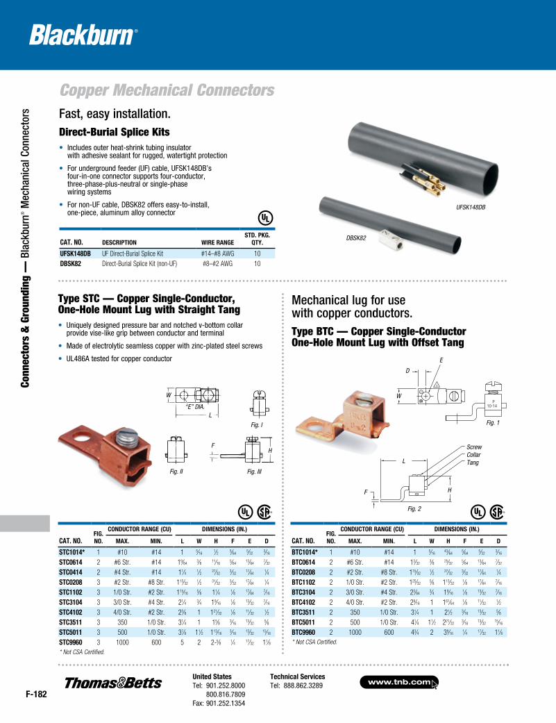
Fast, easy installation.Direct-Burial Splice Kits• Includesouterheat-shrinktubinginsulator
withadhesivesealantforrugged,watertightprotection
• Forundergroundfeeder(UF)cable,UFSK148DB’sfour-in-oneconnectorsupportsfour-conductor,three-phase-plus-neutralorsingle-phasewiringsystems
• Fornon-UFcable,DBSK82offerseasy-to-install,one-piece,aluminumalloyconnector
DBSK82
UFSK148DB
Cat. NO.Fig.NO.
CONDUCtOr raNge (CU) DimeNsiONs (iN.)
max. miN. l W h F e D
stC1014* 1 #10 #14 1 5⁄161⁄2 5⁄64
5⁄323⁄16
stC0614 2 #6 Str. #14 19⁄643⁄8 11⁄16
5⁄6413⁄64
7⁄32
stC0414 2 #4 Str. #14 11⁄4 1⁄2 27⁄323⁄32
17⁄641⁄4
stC0208 3 #2 Str. #8 Str. 115⁄321⁄2 31⁄32
3⁄3217⁄64
1⁄4stC1102 3 1/0 Str. #2 Str. 115⁄16
5⁄8 11⁄4 1⁄8 17⁄647⁄16
stC3104 3 3/0 Str. #4 Str. 21⁄4 3⁄4 19⁄161⁄8 13⁄32
7⁄16
stC4102 3 4/0 Str. #2 Str. 23⁄8 1 121⁄321⁄8 11⁄32
1⁄2stC3511 3 350 1/0 Str. 31⁄4 1 15⁄8 3⁄16
13⁄325⁄8
stC5011 3 500 1/0 Str. 37⁄8 11⁄2 113⁄163⁄16
13⁄3215⁄16
stC9960 3 1000 600 5 2 2-5⁄8 1⁄4 17⁄32 11⁄8* Not CSA Certified.
Cat. NO.Fig.NO.
CONDUCtOr raNge (CU) DimeNsiONs (iN.)
max. miN. l W h F e D
BtC1014* 1 #10 #14 1 5⁄1643⁄64
5⁄645⁄32
3⁄16
BtC0614 2 #6 Str. #14 13⁄323⁄8 25⁄32
5⁄6413⁄64
7⁄32
BtC0208 2 #2 Str. #8 Str. 115⁄321⁄2 27⁄32
3⁄3217⁄64
1⁄4BtC1102 2 1/0 Str. #2 Str. 125⁄32
5⁄8 113⁄321⁄8 17⁄64
7⁄16
BtC3104 2 3/0 Str. #4 Str. 23⁄643⁄4 19⁄16
1⁄8 13⁄327⁄16
BtC4102 2 4/0 Str. #2 Str. 29⁄16 1 161⁄641⁄8 11⁄32
1⁄2BtC3511 2 350 1/0 Str. 31⁄4 1 21⁄2 3⁄16
13⁄325⁄8
BtC5011 2 500 1/0 Str. 41⁄4 11⁄2 221⁄323⁄16
13⁄3215⁄16
BtC9960 2 1000 600 43⁄4 2 39⁄161⁄4 17⁄32 11⁄8
* Not CSA Certified.
Type STC — Copper Single-Conductor, One-Hole Mount Lug with Straight Tang• Uniquelydesignedpressurebarandnotchedv-bottomcollar
providevise-likegripbetweenconductorandterminal
• Madeofelectrolyticseamlesscopperwithzinc-platedsteelscrews
• UL486Atestedforcopperconductor
Mechanical lug for use with copper conductors. Type BTC — Copper Single-Conductor One-Hole Mount Lug with Offset Tang
Fig. 1
Fig. 2
Screw Collar Tang
H
L
F
W
D
E
L
W
“E” DIA.
Fig. I
Fig. II Fig. III
FH
United StatesTel: 901.252.8000 800.816.7809Fax: 901.252.1354
Technical ServicesTel: 888.862.3289www.tnb.com
F-183
Connectors & Grounding —
Blackburn® M
echanical Connectors
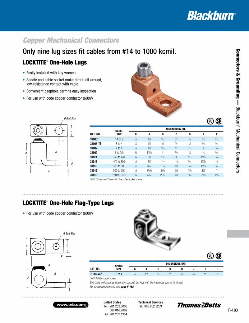
Copper Mechanical ConnectorsOnly nine lug sizes fit cables from #14 to 1000 kcmil.LOCKTITE® One-Hole Lugs
• Easilyinstalledwithkeywrench
• Saddleandcablesocketmakedirect,all-around,low-resistancecontactwithcable
• Convenientpeepholepermitseasyinspection
• Forusewithcodecopperconductor(600V)
Cat. NO.CaBlesize
DimeNsiONs (iN.)
g a B C D J F
31003† 14 to 8 1⁄4 11⁄8 9⁄161⁄2 1⁄8 17⁄32
9⁄32
31005-tB† 8 to 4 1⁄4 11⁄8 5⁄8 1⁄2 1⁄8 17⁄329⁄32
31007 4 to 1 1⁄4 15⁄8 13⁄165⁄8 7⁄32 1 11⁄32
31009 1 to 2/0 3⁄8 115⁄16 1 13⁄161⁄4 13⁄16
7⁄16
31011 2/0 to 4/0 3⁄8 23⁄8 11⁄4 1 9⁄32 113⁄3217⁄32
31013 4/0 to 300 1⁄2 23⁄4 11⁄2 13⁄165⁄16 117⁄32
5⁄831015 300 to 500 1⁄2 31⁄16 111⁄16 13⁄8 11⁄32 113⁄16
3⁄431017 500 to 750 1⁄2 325⁄32 23⁄16 15⁄8 13⁄32 21⁄8 131019 750 to 1000 5⁄8 45⁄16 215⁄32 17⁄8 15⁄32 211⁄32 13⁄16
†With Filister Head Screw. All others, hex socket screws.
Cat. NO.CaBlesize
DimeNsiONs (iN.)
g a B C D J F e
31005-al† 8 to 4 1⁄4 11⁄8 5⁄8 1⁄2 1⁄8 17⁄329⁄32
1⁄2†With Filister Head Screw.Bolt holes and spacings listed are standard, but lugs with blank tongues can be furnished.For torque requirements, see page F-188.
A
G Bolt Size
D
C
BJ
F
G Bolt Size
A
D
C
B
J
F
E
LOCKTITE® One-Hole Flag-Type Lugs
• Forusewithcodecopperconductor(600V)
C
F
B
D
A
J
G Bolt Size
G Bolt Size
C
F
A
B
D
J
E
www.tnb.comUnited StatesTel: 901.252.8000 800.816.7809Fax: 901.252.1354
Technical ServicesTel: 888.862.3289
F-184
Copper Mechanical Connectors
Conn
ecto
rs &
Gro
undi
ng —
Bla
ckbu
rn® M
echa
nica
l Con
nect
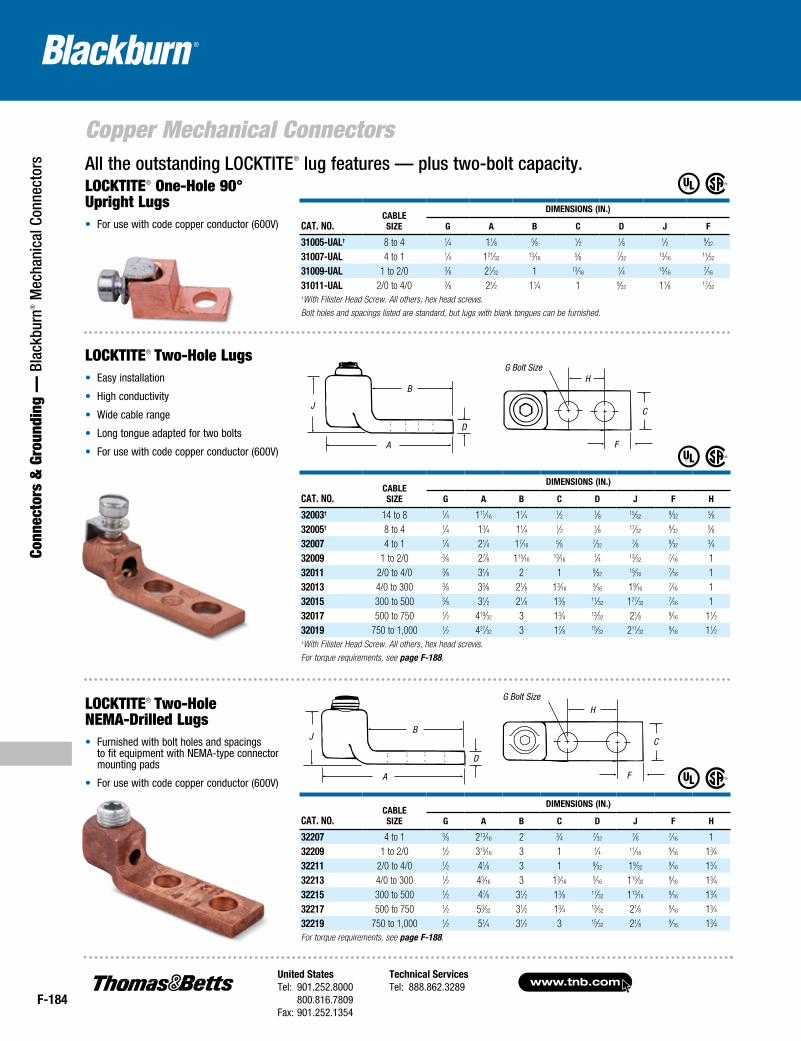
ors All the outstanding LOCKTITE® lug features — plus two-bolt capacity.
LOCKTITE® One-Hole 90° Upright Lugs• For use with code copper conductor (600V)
LOCKTITE® Two-Hole Lugs• Easy installation
• High conductivity
• Wide cable range
• Long tongue adapted for two bolts
• For use with code copper conductor (600V)
LOCKTITE® Two-Hole NEMA-Drilled Lugs• Furnished with bolt holes and spacings
to fit equipment with NEMA-type connector mounting pads
• For use with code copper conductor (600V)
H
A
G Bolt Size
D
C
B
J
F
H
A
G Bolt Size
D
C
B
J
F
H
A
G Bolt Size
D
C
BJ
F
H
A
G Bolt Size
D
C
BJ
F
Cat. No.CableSize
DimeNSioNS (iN.)
G a b C D J F H
32207 4 to 1 3⁄8 213⁄16 2 3⁄4 7⁄327⁄8 7⁄16 1
32209 1 to 2/0 1⁄2 315⁄16 3 1 1⁄4 11⁄169⁄16 13⁄4
32211 2/0 to 4/0 1⁄2 41⁄8 3 1 9⁄32 19⁄329⁄16 13⁄4
32213 4/0 to 300 1⁄2 43⁄16 3 13⁄165⁄16 115⁄32
9⁄16 13⁄432215 300 to 500 1⁄2 47⁄8 31⁄2 13⁄8 11⁄32 113⁄16
9⁄16 13⁄432217 500 to 750 1⁄2 53⁄32 31⁄2 13⁄4 13⁄32 21⁄8 9⁄16 13⁄432219 750 to 1,000 1⁄2 51⁄4 31⁄2 3 15⁄32 21⁄8 9⁄16 13⁄4For torque requirements, see page F-188.
Cat. No.CableSize
DimeNSioNS (iN.)
G a b C D J F H
32003† 14 to 8 1⁄4 111⁄16 11⁄4 1⁄2 1⁄8 15⁄329⁄32
5⁄832005† 8 to 4 1⁄4 13⁄4 11⁄4 1⁄2 1⁄8 17⁄32
9⁄325⁄8
32007 4 to 1 1⁄4 21⁄4 17⁄165⁄8 7⁄32
7⁄8 9⁄323⁄4
32009 1 to 2/0 3⁄8 27⁄8 115⁄1613⁄16
1⁄4 13⁄327⁄16 1
32011 2/0 to 4/0 3⁄8 31⁄8 2 1 9⁄3215⁄16
7⁄16 132013 4/0 to 300 3⁄8 33⁄8 21⁄8 13⁄16
5⁄16 19⁄167⁄16 1
32015 300 to 500 3⁄8 31⁄2 21⁄8 13⁄8 11⁄32 127⁄327⁄16 1
32017 500 to 750 1⁄2 419⁄32 3 13⁄4 13⁄32 21⁄8 9⁄16 11⁄232019 750 to 1,000 1⁄2 427⁄32 3 17⁄8 15⁄32 211⁄32
9⁄16 11⁄2†With Filister Head Screw. All others, hex head screws.For torque requirements, see page F-188.
Cat. No.CableSize
DimeNSioNS (iN.)
G a b C D J F
31005-Ual† 8 to 4 1⁄4 11⁄8 5⁄8 1⁄2 1⁄8 1⁄2 9⁄32
31007-Ual 4 to 1 1⁄4 121⁄3213⁄16
5⁄8 7⁄3213⁄16
11⁄32
31009-Ual 1 to 2/0 3⁄8 21⁄32 1 13⁄161⁄4 15⁄16
7⁄16
31011-Ual 2/0 to 4/0 3⁄8 21⁄2 11⁄4 1 9⁄32 11⁄8 17⁄32
†With Filister Head Screw. All others, hex head screws.Bolt holes and spacings listed are standard, but lugs with blank tongues can be furnished.
G Bolt SizeH
C
F
B
D
A
J
HG Bolt Size
C
F
D
B
A
J
United StatesTel: 901.252.8000 800.816.7809Fax: 901.252.1354
Technical ServicesTel: 888.862.3289www.tnb.com
F-185
Connectors & Grounding —
Blackburn® M
echanical Connectors
Copper Mechanical Connectors
Cat. No.CableSize FiG.
bolt Size
DimeNSioNS (iN.)
a b C D e F H J
32003bD† 14 to 8 A 1⁄4 23⁄16 13⁄4 5⁄8 1⁄8 11⁄169⁄32
5⁄8 15⁄32
32005bD† 8 to 4 A 1⁄4 21⁄2 2 1 1⁄8 1 9⁄325⁄8 17⁄32
32007bD 4 to 1 A 3⁄8 213⁄16 2 11⁄4 7⁄32 11⁄4 7⁄16 1 29⁄32
32009bD 1 to 2/0 A 1⁄2 47⁄16 31⁄2 11⁄2 1⁄4 19⁄165⁄8 13⁄4 13⁄32
32011bD 2/0 to 4/0 A 1⁄2 45⁄8 31⁄2 13⁄4 9⁄32 13⁄4 5⁄8 13⁄4 15⁄16
32013bD 4/0 to 300 A 1⁄2 43⁄4 31⁄2 2 5⁄16 21⁄8 5⁄8 13⁄4 19⁄16
32015bD 300 to 500 A 1⁄2 53⁄8 315⁄16 21⁄2 11⁄32 21⁄2 5⁄8 13⁄4 113⁄16
32017bD 500 to 700 B 1⁄2 519⁄32 4 4 13⁄32 215⁄165⁄8 13⁄4 21⁄8
32019bD 750 to 1000 B 1⁄2 527⁄32 4 4 15⁄32 31⁄4 5⁄8 13⁄4 211⁄32
32011tb 2/0 to 4/0 C 1⁄2 45⁄8 33⁄8 21⁄2 9⁄32 23⁄4 5⁄8 13⁄4 15⁄16
32013tb 4/0 to 300 C 1⁄2 43⁄4 31⁄2 3 5⁄16 31⁄4 5⁄8 13⁄4 117⁄32
32015tb 300 to 500 D 1⁄2 53⁄8 4 4 11⁄32 33⁄4 5⁄8 13⁄4 113⁄16
32017tb 500 to 750 D 1⁄2 519⁄32 4 4 13⁄32 43⁄8 5⁄8 13⁄4 21⁄832019tb 750 to 1,000 D 1⁄2 527⁄32 4 4 15⁄32 413⁄16
5⁄8 13⁄4 211⁄32
†With Filister Head Screw. For torque requirements, see page F-188.
LOCKTITE® Double- and Triple-Barrel NEMA-Drilled Lugs for 600V Applications• Screw tightening
• Serrated saddle
• Built-in lockwasher
• For use with code copper conductor (600V)
Bolt Size
E
A
B
D
FH
C
J
Fig. A
Bolt Size
E
A
B
D
FH
C
J
H
Fig. B
Bolt Size
E
AB
D
FH
C
J
Fig. C
Bolt Size
E
AB
D
FH
C
J
H
Fig. D
All the same features as the standard LOCKTITE® lug — with two or three barrels.
C
FH
E
Bolt Size
Bolt SizeBolt Size
AB
DJ
E CH
H F
D
AB
JD
AB
J
E C
H F
Bolt Size
E CH
FH
D
AB
J
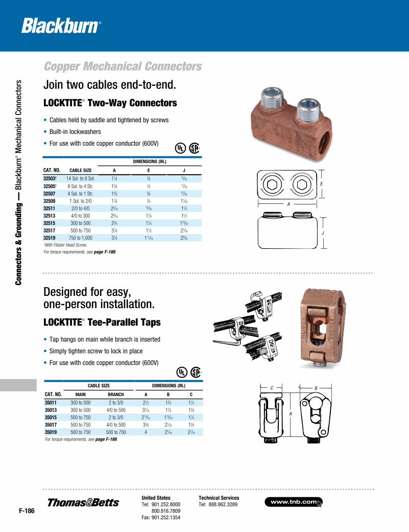
www.tnb.comUnited StatesTel: 901.252.8000 800.816.7809Fax: 901.252.1354
Technical ServicesTel: 888.862.3289
F-186
Copper Mechanical Connectors
Conn
ecto
rs &
Gro
undi
ng —
Bla
ckbu
rn® M
echa
nica
l Con
nect
ors Join two cables end-to-end.
LOCKTITE® Two-Way Connectors
• Cables held by saddle and tightened by screws
• Built-in lockwashers
• For use with code copper conductor (600V)
Designed for easy, one-person installation.LOCKTITE® Tee-Parallel Taps
• Tap hangs on main while branch is inserted
• Simply tighten screw to lock in place
• For use with code copper conductor (600V)
Cat. No. Cable Size
DimeNSioNS (iN.)
a e J
32503† 14 Sol. to 8 Sol. 11⁄8 3⁄8 15⁄32
32505† 8 Sol. to 4 Str. 13⁄8 1⁄2 17⁄32
32507 4 Sol. to 1 Str. 15⁄8 5⁄8 27⁄32
32509 1 Sol. to 2/0 17⁄8 3⁄4 11⁄32
32511 2/0 to 4/0 25⁄1615⁄16 11⁄4
32513 4/0 to 300 29⁄16 11⁄8 11⁄232515 300 to 500 23⁄4 11⁄4 125⁄32
32517 500 to 750 31⁄8 11⁄2 21⁄16
32519 750 to 1,000 37⁄8 111⁄16 29⁄32
†With Filister Head Screw.For torque requirements, see page F-188.
A
E
J
A
C BCat. No.
Cable Size DimeNSioNS (iN.)
maiN braNCh a b C
35011 300 to 500 2 to 3/0 21⁄2 13⁄4 11⁄435013 300 to 500 4/0 to 500 31⁄16 17⁄8 15⁄835015 500 to 750 2 to 3/0 213⁄16 115⁄16 11⁄435017 500 to 750 4/0 to 500 33⁄8 21⁄16 15⁄835019 500 to 750 500 to 750 4 21⁄16 21⁄16
For torque requirements, see page F-188.
E
A
J
A
BC
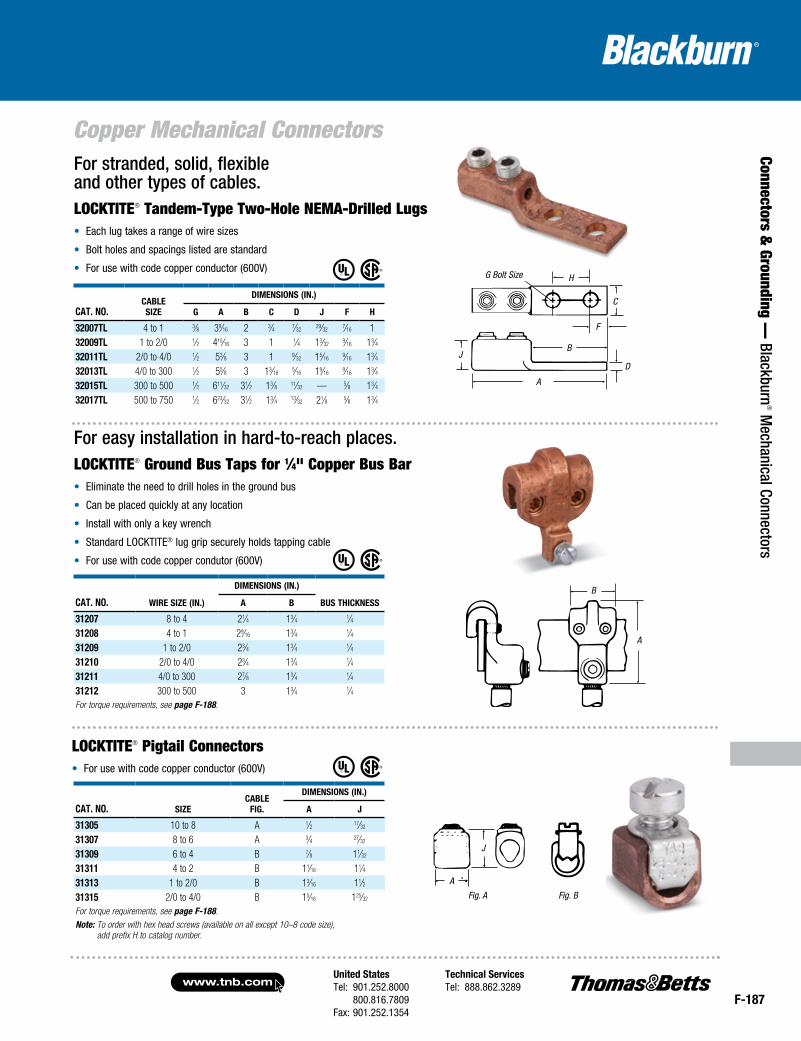
United StatesTel: 901.252.8000 800.816.7809Fax: 901.252.1354
Technical ServicesTel: 888.862.3289www.tnb.com
F-187
Connectors & Grounding —
Blackburn® M
echanical Connectors
Copper Mechanical ConnectorsFor stranded, solid, flexible and other types of cables.LOCKTITE® Tandem-Type Two-Hole NEMA-Drilled Lugs• Each lug takes a range of wire sizes
• Bolt holes and spacings listed are standard
• For use with code copper conductor (600V)
For easy installation in hard-to-reach places.LOCKTITE® Ground Bus Taps for 1⁄4" Copper Bus Bar• Eliminate the need to drill holes in the ground bus
• Can be placed quickly at any location
• Install with only a key wrench
• Standard LOCKTITE® lug grip securely holds tapping cable
• For use with code copper condutor (600V)
LOCKTITE® Pigtail Connectors• For use with code copper conductor (600V)
Cat. No.CableSize
DimeNSioNS (iN.)
G a b C D J F h
32007tl 4 to 1 3⁄8 39⁄16 2 3⁄4 7⁄3229⁄32
7⁄16 132009tl 1 to 2/0 1⁄2 415⁄16 3 1 1⁄4 13⁄32
9⁄16 13⁄432011tl 2/0 to 4/0 1⁄2 53⁄8 3 1 9⁄32 15⁄16
9⁄16 13⁄432013tl 4/0 to 300 1⁄2 55⁄8 3 13⁄16
5⁄16 19⁄169⁄16 13⁄4
32015tl 300 to 500 1⁄2 611⁄32 31⁄2 13⁄8 11⁄32 — 5⁄8 13⁄432017tl 500 to 750 1⁄2 623⁄32 31⁄2 13⁄4 13⁄32 21⁄8 5⁄8 13⁄4
G Bolt Size
J
H
C
D
A
B
F
B
A
J
A Fig. B
Cat. No. Wire Size (iN.)
DimeNSioNS (iN.)
buS thiCkNeSSa b
31207 8 to 4 21⁄4 13⁄4 1⁄431208 4 to 1 29⁄16 13⁄4 1⁄431209 1 to 2/0 23⁄4 13⁄4 1⁄431210 2/0 to 4/0 23⁄4 13⁄4 1⁄431211 4/0 to 300 27⁄8 13⁄4 1⁄431212 300 to 500 3 13⁄4 1⁄4For torque requirements, see page F-188.
Cat. No. SizeCable
FiG.
DimeNSioNS (iN.)
a J
31305 10 to 8 A 1⁄2 17⁄32
31307 8 to 6 A 3⁄4 27⁄32
31309 6 to 4 B 7⁄8 11⁄32
31311 4 to 2 B 11⁄16 11⁄431313 1 to 2/0 B 13⁄16 11⁄231315 2/0 to 4/0 B 15⁄16 125⁄32
For torque requirements, see page F-188.Note: To order with hex head screws (available on all except 10–8 code size),
add prefix H to catalog number.
J
AFig. A
B
A
H
C
F
DJ
G Bolt Size
B
A
J
A
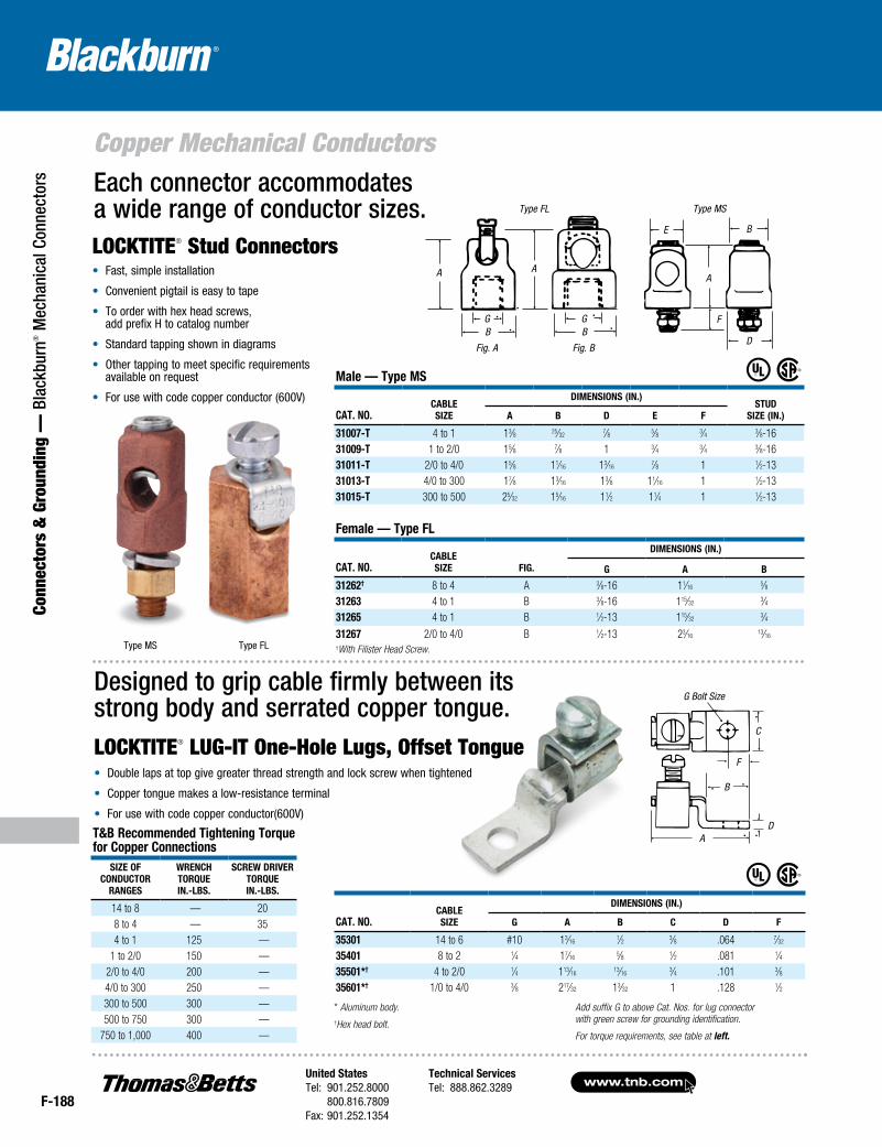
www.tnb.comUnited StatesTel: 901.252.8000 800.816.7809Fax: 901.252.1354
Technical ServicesTel: 888.862.3289
F-188
Copper Mechanical Conductors
Conn
ecto
rs &
Gro
undi
ng —
Bla
ckbu
rn® M
echa
nica
l Con
nect
ors
Designed to grip cable firmly between its strong body and serrated copper tongue.LOCKTITE® LUG-IT One-Hole Lugs, Offset Tongue• Double laps at top give greater thread strength and lock screw when tightened
• Copper tongue makes a low-resistance terminal
• For use with code copper conductor(600V)D
F
B
C
A
Male — Type MS
CaT. No.CableSize
DiMeNSioNS (iN.)STuD
Size (iN.)a b D e F
31007-T 4 to 1 13⁄8 25⁄327⁄8 5⁄8 3⁄4 3⁄8-16
31009-T 1 to 2/0 15⁄8 7⁄8 1 3⁄4 3⁄4 3⁄8-1631011-T 2/0 to 4/0 15⁄8 11⁄16 13⁄16
7⁄8 1 1⁄2-1331013-T 4/0 to 300 17⁄8 13⁄16 13⁄8 11⁄16 1 1⁄2-1331015-T 300 to 500 25⁄32 15⁄16 11⁄2 11⁄4 1 1⁄2-13
GB
A A
GB
Fig. A Fig. B
Type FL
LOCKTITE® Stud Connectors• Fast, simple installation
• Convenient pigtail is easy to tape
• To order with hex head screws, add prefix H to catalog number
• Standard tapping shown in diagrams
• Other tapping to meet specific requirements available on request
• For use with code copper conductor (600V)
D
F
A
E B
Type MS
Female — Type Fl
CaT. No.Cable Size Fig.
DiMeNSioNS (iN.)
g a b
31262† 8 to 4 A 3⁄8-16 11⁄165⁄8
31263 4 to 1 B 3⁄8-16 115⁄323⁄4
31265 4 to 1 B 1⁄2-13 115⁄323⁄4
31267 2/0 to 4/0 B 1⁄2-13 23⁄1613⁄16
†With Filister Head Screw.
Each connector accommodates a wide range of conductor sizes.
Type MS Type FL
* Aluminum body.†Hex head bolt.
Add suffix G to above Cat. Nos. for lug connec tor with green screw for grounding identification.
For torque requirements, see table at left.
T&b Recommended Tightening Torque for Copper Connections
Size oFCoNDuCToR
RaNgeS
WReNChToRqueiN.-lbS.
SCReW DRiveRToRqueiN.-lbS.
14 to 8 — 208 to 4 — 354 to 1 125 —
1 to 2/0 150 — 2/0 to 4/0 200 — 4/0 to 300 250 — 300 to 500 300 — 500 to 750 300 —
750 to 1,000 400 —
CaT. No.CableSize
DiMeNSioNS (iN.)
g a b C D F
35301 14 to 6 #10 13⁄161⁄2 3⁄8 .064 7⁄32
35401 8 to 2 1⁄4 17⁄165⁄8 1⁄2 .081 1⁄4
35501*† 4 to 2/0 1⁄4 113⁄1613⁄16
3⁄4 .101 3⁄835601*† 1/0 to 4/0 3⁄8 217⁄32 13⁄32 1 .128 1⁄2
BB
BE
A
F
D
AA
GG
C
F
B
DA
G Bolt Size
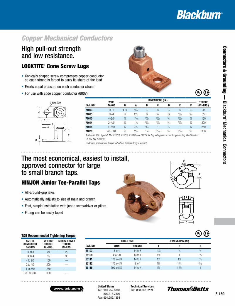
United StatesTel: 901.252.8000 800.816.7809Fax: 901.252.1354
Technical ServicesTel: 888.862.3289www.tnb.com
F-189
Connectors & Grounding —
Blackburn® M
echanical Connectors
Copper Mechanical Conductors
T&b Recommended Tightening TorqueSize oF
CoNDuCToRRaNgeS
WReNChToRqueiN.-lbS.
SCReW DRiveRToRqueiN.-lbS.
14 to 8 20 2014 to 4 35 354 to 2/0 150 —2 to 4/0 200 —1 to 250 250 —
2/0 to 500 300 —
High pull-out strength and low resistance.LOCKTITE® Cone Screw Lugs
• Conically shaped screw compresses copper conductor so each strand is forced to carry its share of the load
• Exerts equal pressure on each conductor strand
• For use with code copper conductor (600V)
CaT. No.WiRe
RaNge
DiMeNSioNS (iN.)ToRque
(iN.-lbS.)g a b C D e F
71003 14–8 #10 13⁄167⁄16
3⁄8 3⁄323⁄8 3⁄16 20*
71005 14–4 1⁄4 15⁄325⁄8 9⁄16
1⁄8 19⁄329⁄32 35*
71010 4–2/0 3⁄8 121⁄3227⁄32
23⁄323⁄16
25⁄323⁄8 150
71014 2–4/0 3⁄8 17⁄8 29⁄3215⁄16
3⁄1631⁄32
3⁄8 200 71015 1–250 3⁄8 21⁄32
29⁄32 1 7⁄32 1 3⁄8 250 71020 2/0–500 1⁄2 23⁄4 11⁄4 111⁄32
9⁄32 115⁄329⁄16 300
Add suffix G to lug Cat. No. 71003, 71005, 71010 and 71014 for lug with green screw for grounding identification.UL File No. E-9609.*Indicates screwdriver torque; all others indicate torque wrench.
Bmax.
Amax.
CBmax.
Amax.
C
CaT. No.
Cable Size DiMeNSioNS (iN.)
MaiN bRaNCh a b C
35107 8 to 4 14 to 8 11⁄167⁄8 5⁄8
35109 4 to 1/0 14 to 4 11⁄4 1 11⁄16
35111 1/0 to 4/0 14 to 4 13⁄4 13⁄8 27⁄32
35112 1/0 to 4/0 8 to 1 15⁄8 19⁄1627⁄32
35115 300 to 500 14 to 4 17⁄8 113⁄16 1
The most economical, easiest to install, approved connector for large to small branch taps.HINJON Junior Tee-Parallel Taps
• All-around-grip jaws
• Automatically adjusts to size of main and branch
• Fast, simple installation with just a screwdriver or pliers
• Fitting can be easily taped
C
Amax.
Bmax.
G Bolt Size
E
A
F
B
C
D
E
AB
D
F
C
G Bolt Size
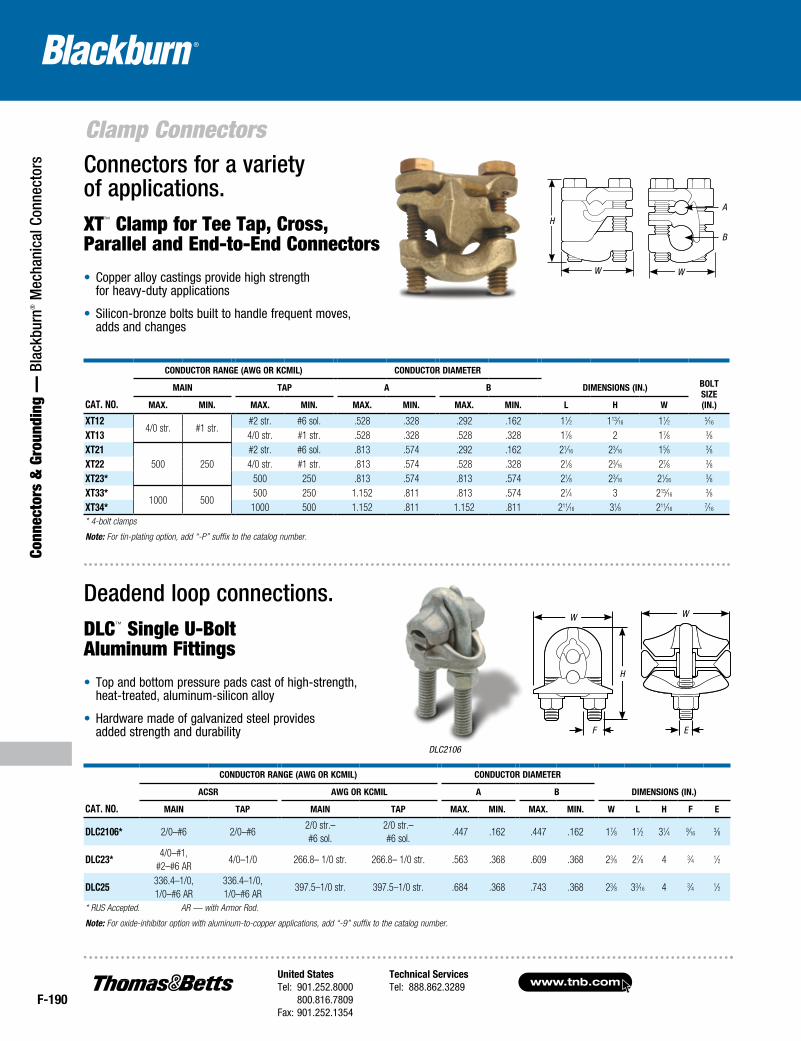
F-190
Clamp Connectors
Conn
ecto
rs &
Gro
undi
ng —
Bla
ckbu
rn® M
echa
nica
l Con
nect
ors
www.tnb.comUnited StatesTel: 901.252.8000 800.816.7809Fax: 901.252.1354
Technical ServicesTel: 888.862.3289
CAT. NO.
CONduCTOr rANge (AWg Or kCmil) CONduCTOr diAmeTer
dimeNsiONs (iN.) BOlTsize(iN.)
mAiN TAp A B
mAx. miN. mAx. miN. mAx. miN. mAx. miN. l H W
xT124/0 str. #1 str.
#2 str. #6 sol. .528 .328 .292 .162 11⁄2 113⁄16 11⁄2 5⁄16
xT13 4/0 str. #1 str. .528 .328 .528 .328 17⁄8 2 17⁄8 3⁄8xT21
500 250#2 str. #6 sol. .813 .574 .292 .162 21⁄16 23⁄16 15⁄8 3⁄8
xT22 4/0 str. #1 str. .813 .574 .528 .328 21⁄8 23⁄16 27⁄8 3⁄8xT23* 500 250 .813 .574 .813 .574 21⁄8 23⁄16 21⁄26
3⁄8xT33*
1000 500500 250 1.152 .811 .813 .574 21⁄4 3 215⁄16
3⁄8xT34* 1000 500 1.152 .811 1.152 .811 211⁄16 31⁄8 211⁄16
7⁄16
* 4-bolt clamps
Note: For tin-plating option, add “-P” suffix to the catalog number.
Connectors for a variety of applications.XT™ Clamp for Tee Tap, Cross, Parallel and End-to-End Connectors
• Copper alloy castings provide high strength for heavy-duty applications
• Silicon-bronze bolts built to handle frequent moves, adds and changes
DLC2106
H
W W
A
B
CAT. NO.
CONduCTOr rANge (AWg Or kCmil) CONduCTOr diAmeTer
dimeNsiONs (iN.)ACsr AWg Or kCmil A B
mAiN TAp mAiN TAp mAx. miN. mAx. miN. W l H F e
dlC2106* 2/0–#6 2/0–#62/0 str.– #6 sol.
2/0 str.– #6 sol.
.447 .162 .447 .162 17⁄8 11⁄2 31⁄4 9⁄163⁄8
dlC23*4/0–#1,
#2–#6 AR4/0–1/0 266.8– 1/0 str. 266.8– 1/0 str. .563 .368 .609 .368 23⁄8 27⁄8 4 3⁄4 1⁄2
dlC25336.4–1/0, 1/0–#6 AR
336.4–1/0, 1/0–#6 AR
397.5–1/0 str. 397.5–1/0 str. .684 .368 .743 .368 23⁄8 33⁄16 4 3⁄4 1⁄2
* RUS Accepted. AR — with Armor Rod.
Note: For oxide-inhibitor option with aluminum-to-copper applications, add “-9” suffix to the catalog number.
W
H
F E
W
Deadend loop connections.DLC™ Single U-Bolt Aluminum Fittings
• Top and bottom pressure pads cast of high-strength, heat-treated, aluminum-silicon alloy
• Hardware made of galvanized steel provides added strength and durability