Embed Size (px)
Citation preview
GLOBAL SPECIALIST IN ELECTRICALAND DIGITAL BUILDING INFRASTRUCTURE
Distributed by
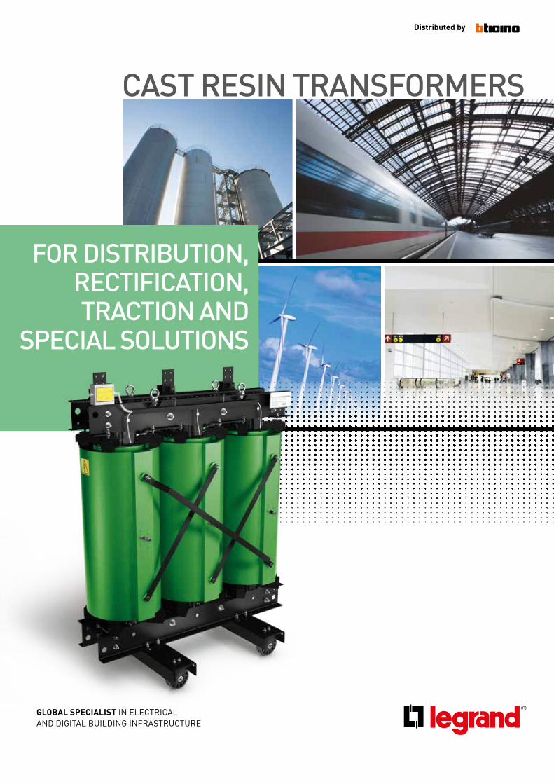
CAST RESIN TRANSFORMERS
FOR DISTRIBUTION, RECTIFICATION, TRACTION AND
SPECIAL SOLUTIONS

2
3CAST RESIN TRANSFORMERS INDEX
INDEXGeneral features 4Applications 6Standard 8Advantages of cast resin transformers 10Economic advantages 12CRT technology 14Service Conditions 18Protection against overvoltages 19Protection against temperature rise 20Ventilation of the Transformers 21Vectorial groups 24
Selectioncriteria
4 - 24
Generalfeatures
25 - 40
CatalogueGreen Transformers
CatalogueRed Transformers
Installation and maintenance
41 - 50
51 - 60
61 - 76
CRT Range 25Green T.HE 27Red transformers 30Special offer 32
GREEN T.HE transformers for european market 41 Technical information – GREEN T.HE TIER 1 42Technical information – GREEN T.HE TIER 2 46Accessories for transformers (GREEN reg.548) 49
Transformers for the rest of the world comply with IEC standard 51Technical information - BoBk 52Technical information - XC 54Technical information - NL 56Accessories for transformers (BoBk-XC-NL) 59
Safety guidelines 62Rating plate 63Transport, receipt and storage 64Installation 67Commissioning 71Maintenance 74Technical glossary 76
4
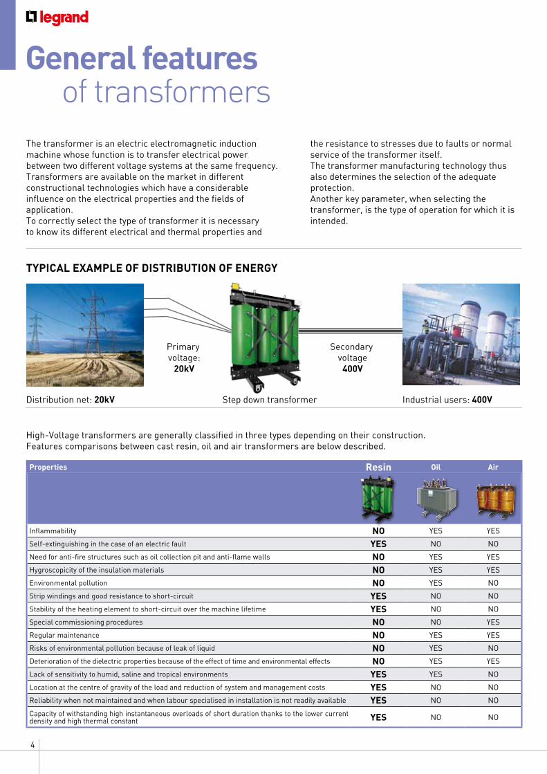
The transformer is an electric electromagnetic induction machine whose function is to transfer electrical power between two different voltage systems at the same frequency. Transformers are available on the market in different constructional technologies which have a considerable influence on the electrical properties and the fields of application. To correctly select the type of transformer it is necessary to know its different electrical and thermal properties and
Properties Resin Oil Air
Inflammability NO YES YES
Self-extinguishing in the case of an electric fault YES NO NO
Need for anti-fire structures such as oil collection pit and anti-flame walls NO YES YES
Hygroscopicity of the insulation materials NO YES YES
Environmental pollution NO YES NO
Strip windings and good resistance to short-circuit YES NO NO
Stability of the heating element to short-circuit over the machine lifetime YES NO NO
Special commissioning procedures NO NO YES
Regular maintenance NO YES YES
Risks of environmental pollution because of leak of liquid NO YES NO
Deterioration of the dielectric properties because of the effect of time and environmental effects NO YES YES
Lack of sensitivity to humid, saline and tropical environments YES YES NO
Location at the centre of gravity of the load and reduction of system and management costs YES NO NO
Reliability when not maintained and when labour specialised in installation is not readily available YES NO NO
Capacity of withstanding high instantaneous overloads of short duration thanks to the lower current density and high thermal constant YES NO NO
High-Voltage transformers are generally classified in three types depending on their construction. Features comparisons between cast resin, oil and air transformers are below described.
General featuresof transformers
TYPICAL EXAMPLE OF DISTRIBUTION OF ENERGY
Distribution net: 20kV
Primary voltage:
20kV
Step down transformer
Secondary voltage 400V
Industrial users: 400V
the resistance to stresses due to faults or normal service of the transformer itself. The transformer manufacturing technology thus also determines the selection of the adequate protection. Another key parameter, when selecting the transformer, is the type of operation for which it is intended.
5CAST RESIN TRANSFORMERS SELECTION CRITERIA
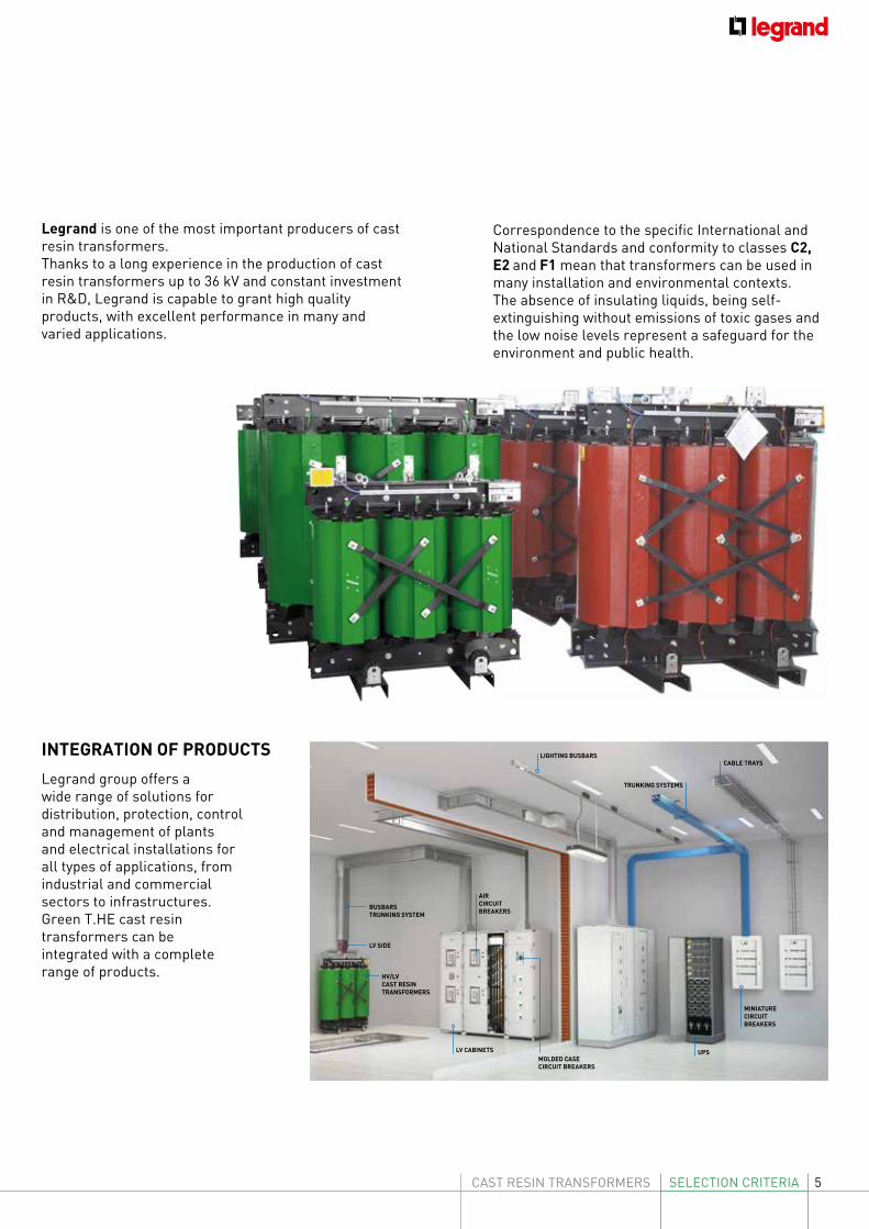
Legrand is one of the most important producers of cast resin transformers.Thanks to a long experience in the production of cast resin transformers up to 36 kV and constant investment in R&D, Legrand is capable to grant high quality products, with excellent performance in many and varied applications.
Legrand group offers a wide range of solutions for distribution, protection, control and management of plants and electrical installations for all types of applications, from industrial and commercial sectors to infrastructures.Green T.HE cast resin transformers can be integrated with a complete range of products.
INTEGRATION OF PRODUCTS LIGHTING BUSBARS
TRUNKING SYSTEMS
CABLE TRAYS
MINIATURECIRCUITBREAKERS
AIRCIRCUITBREAKERS
HV/LV CAST RESINTRANSFORMERS
LV CABINETSMOLDED CASE CIRCUIT BREAKERS
BUSBARSTRUNKING SYSTEM
LV SIDE
UPS
Correspondence to the specific International and National Standards and conformity to classes C2, E2 and F1 mean that transformers can be used in many installation and environmental contexts. The absence of insulating liquids, being self-extinguishing without emissions of toxic gases and the low noise levels represent a safeguard for the environment and public health.
6
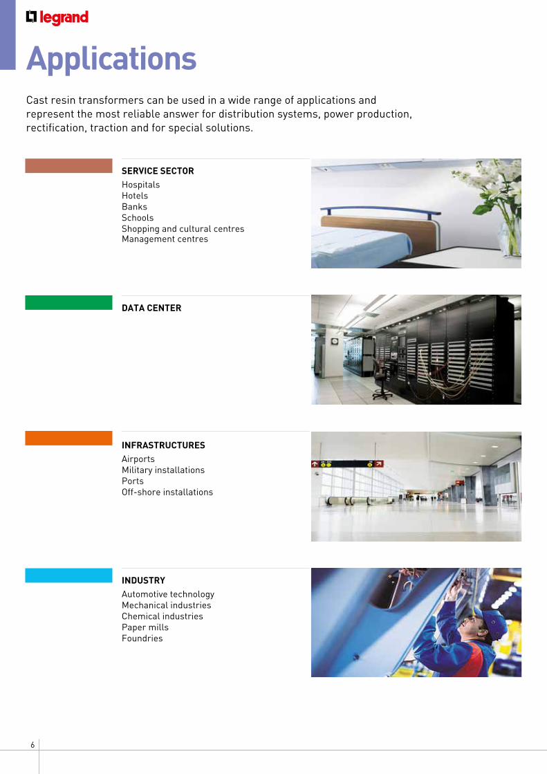
Applications Cast resin transformers can be used in a wide range of applications and represent the most reliable answer for distribution systems, power production, rectification, traction and for special solutions.
SERVICE SECTOR HospitalsHotelsBanks SchoolsShopping and cultural centresManagement centres
INFRASTRUCTURES AirportsMilitary installations PortsOff-shore installations
INDUSTRY Automotive technologyMechanical industriesChemical industriesPaper millsFoundries
DATA CENTER
7CAST RESIN TRANSFORMERS SELECTION CRITERIA
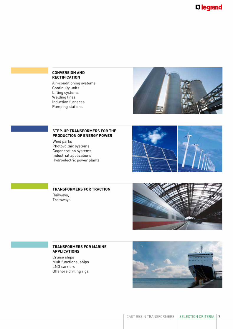
CONVERSION AND RECTIFICATION Air-conditioning systemsContinuity unitsLifting systemsWelding linesInduction furnacesPumping stations
STEP-UP TRANSFORMERS FOR THE PRODUCTION OF ENERGY POWER Wind parksPhotovoltaic systemsCogeneration systemsIndustrial applicationsHydroelectric power plants
TRANSFORMERS FOR TRACTION Railways;Tramways
TRANSFORMERS FOR MARINE APPLICATIONS Cruise shipsMultifunctional shipsLNG carriersOffshore drilling rigs
8
Standard
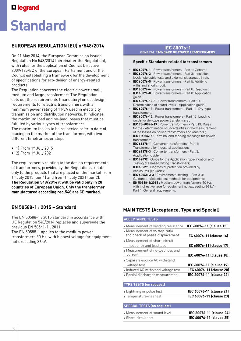
Specific Standards related to transformers
• IEC 60076-1 : Power transformers - Part 1: General;• IEC 60076-3 : Power transformers - Part 3: Insulation levels, dielectric tests and external clearances in air;• IEC 60076-5 : Power transformers - Part 5: Ability to withstand short circuit;• IEC 60076-6 : Power transformers - Part 6: Reactors;• IEC 60076-8 : Power transformers - Part 8: Application guide;• IEC 60076-10-1 : Power transformers - Part 10-1: Determination of sound levels - Application guide;• IEC 60076-11 : Power transformers - Part 11: Dry-type transformers;• IEC 60076-12 : Power transformers - Part 12: Loading guide for dry-type power transformers ;• IEC TS 60076-19 : Power transformers - Part 19: Rules for the determination of uncertainties in the measurement of the losses on power transformers and reactors ;• IEC TR 60616 : Terminal and tapping markings for power transformers;• IEC 61378-1 : Converter transformers - Part 1: Transformers for industrial applications;• IEC 61378-3 : Converter transformers - Part 3: Application guide;• IEC 62032 : Guide for the Application, Specification and Testing of Phase-Shifting Transformers;• IEC 60529 : Degrees of protection provided by enclosures (IP Code);• IEC 60068-3-3 : Environmental testing - Part 3-3: Guidance - Seismic test methods for equipments;• EN 50588-1:2015 : Medium power transformers 50 Hz, with highest voltage for equipment not exceeding 36 kV - Part 1: General requirements;
MAIN TESTS (Acceptance, Type and Special)
EUROPEAN REGULATION (EU) n°548/2014
On 21 May 2014, the European Commission issued Regulation No 548/2014 (hereinafter the Regulation), with rules for the application of Council Directive 2009/125/EC of the European Parliament and of the Council establishing a framework for the development of specifications for eco-design of energy-related products. The Regulation concerns the electric power small, medium and large transformers.The Regulation sets out the requirements (mandatory) on ecodesign requirements for electric transformers with a minimum power rating of 1 kVA used in electricity transmission and distribution networks. It indicates the maximum load and no-load losses that must be fulfilled by various types of transformers.The maximum losses to be respected refer to date of placing on the market of the transformer, with two different timeframes or steps:
• 1) From 1st July 2015 • 2) From 1st July 2021
The requirements relating to the design requirements of transformers, provided by the Regulations, relate only to the products that are placed on the market from 1st July 2015 (tier 1) and from 1st July 2021 (tier 2).The Regulation 548/2014 it will be valid only in 28 countries of European Union. Only the transformer manufactured according reg.548 are CE marked.
EN 50588-1 : 2015 – Standard The EN 50588-1 : 2015 standard in accordance with UE Regulation 548/2014 replaces and supersede the previous EN 50541-1 : 2011.The EN 50588-1 applies to the medium power transformers 50 Hz, with highest voltage for equipment not exceeding 36kV.
ACCEPTANCE TESTS
Measurement of winding resistance IEC 60076-11 (clause 15) Measurement of voltage ratio
and check of phase displacement IEC 60076-11 (clause 16) Measurement of short-circuit
impedance and load loss IEC 60076-11 (clause 17) Measurement of no-load loss and
current IEC 60076-11 (clause 18) Separate-source AC withstand
voltage test IEC 60076-11 (clause 19) Induced AC withstand voltage test IEC 60076-11 (clause 20) Partial discharges measurement IEC 60076-11 (clause 22)
TYPE TESTS (on request)
Lightning impulse test IEC 60076-11 (clause 21) Temperature-rise test IEC 60076-11 (clause 23)
SPECIAL TESTS (on request)
Measurement of sound level IEC 60076-11 (clause 24) Short-circuit test IEC 60076-11 (clause 25)
IEC 60076-1GENERAL STANDARD OF POWER TRANSFORMERS
9CAST RESIN TRANSFORMERS SELECTION CRITERIA
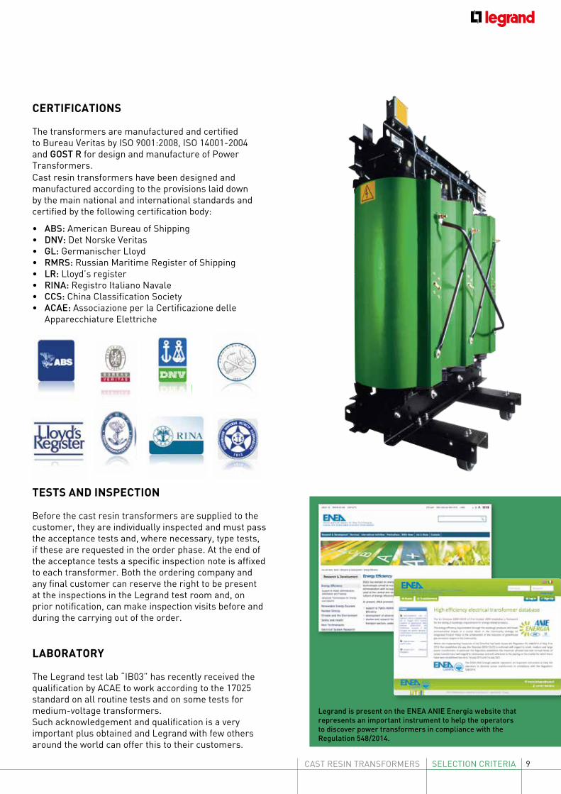
CERTIFICATIONS
The transformers are manufactured and certified to Bureau Veritas by ISO 9001:2008, ISO 14001-2004 and GOST R for design and manufacture of Power Transformers.Cast resin transformers have been designed and manufactured according to the provisions laid down by the main national and international standards and certified by the following certification body:
• ABS: American Bureau of Shipping• DNV: Det Norske Veritas• GL: Germanischer Lloyd• RMRS: Russian Maritime Register of Shipping• LR: Lloyd’s register• RINA: Registro Italiano Navale• CCS: China Classification Society• ACAE: Associazione per la Certificazione delle
Apparecchiature Elettriche
LABORATORY
The Legrand test lab “IB03” has recently received the qualification by ACAE to work according to the 17025 standard on all routine tests and on some tests for medium-voltage transformers.Such acknowledgement and qualification is a very important plus obtained and Legrand with few others around the world can offer this to their customers.
TESTS AND INSPECTION
Before the cast resin transformers are supplied to the customer, they are individually inspected and must pass the acceptance tests and, where necessary, type tests, if these are requested in the order phase. At the end of the acceptance tests a specific inspection note is affixed to each transformer. Both the ordering company and any final customer can reserve the right to be present at the inspections in the Legrand test room and, on prior notification, can make inspection visits before and during the carrying out of the order.
Legrand is present on the ENEA ANIE Energia website that represents an important instrument to help the operators to discover power transformers in compliance with the Regulation 548/2014.
10
Advantages of cast resin transformers
1. REDUCTION OF ENVIRONMENTAL IMPACT
• Higher safety (low risk of fire)Thanks to the use of high-quality epoxy resin, Legrand cast resin transformers reduce environmental impact to a minimum and conform to the international environmental standards IEC 60076-11.The transformers are entirely manufactured with flame-retardant and self-extinguishing materials.They therefore have reduced inflammability (self-extinguishing) and a minimum emission of toxic gases and opaque smokes (F1 fire resistance classification); they can work in damp, dusty, saline or polluted environments (E2 environmental test classification) and offer high resistance to thermal shocks (C2 climatic test classification).
• No cooling fluidsBecause they have no cooling fluids cast resin transformers do not present risks of pollution and drastically reduce their contribution when there is a fire, as compared with transformers using insulating liquid.
• Recovery of materials at the end of lifeCast resin transformers can be considered as the construction which more respects the environment.This is particularly important when the machine has come to the end of its working life and must be disposed. At the end of the disposal the resin is considered an inert material and the primary and secondary windings can easily be recycled.
• Low CO2 emissionsReducing the consumptions of a transformer also means decreasing CO2 emissions, limiting the impact of the machine on the environment.Taking the example of potential saving as reference, it is clear that during the 20 years of operation, Green T.HE ensures a reduction of over 112 tonnes in emissions of CO2 into the atmosphere.This extremely important environmental advantage also becomes an economical advantage in those countries where carbon emissions laws based on the quantity of CO2 emitted has been introduced.In these countries, companies who do not comply with fixed carbon dioxide limits must pay for any excess, while companies that are committed to preserving the environment will not have to sustain the burden of this additional charge, in addition to being able to sell carbon credits, and therefore turn them into financial advantage, CO2 credits.
The manufacturing characteristics of cast resin transformers mean that they can be usedfor most installations. Their main advantages with respect to oil transformers can be expressed in three characteristics:
1. reduction of environmental impact2. simplification of installation3. flexibility in use
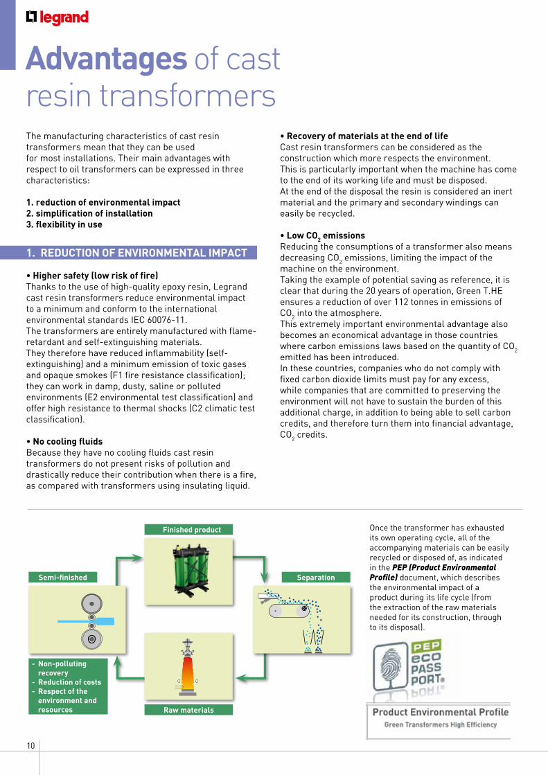
Once the transformer has exhausted its own operating cycle, all of the accompanying materials can be easily recycled or disposed of, as indicated in the PEP (Product Environmental Profile) document, which describes the environmental impact of a product during its life cycle (from the extraction of the raw materials needed for its construction, through to its disposal).
Semi-finished
Finished product
Raw materials
Separation
- Non-polluting recovery- Reduction of costs- Respect of the environment and resources
11CAST RESIN TRANSFORMERS SELECTION CRITERIA
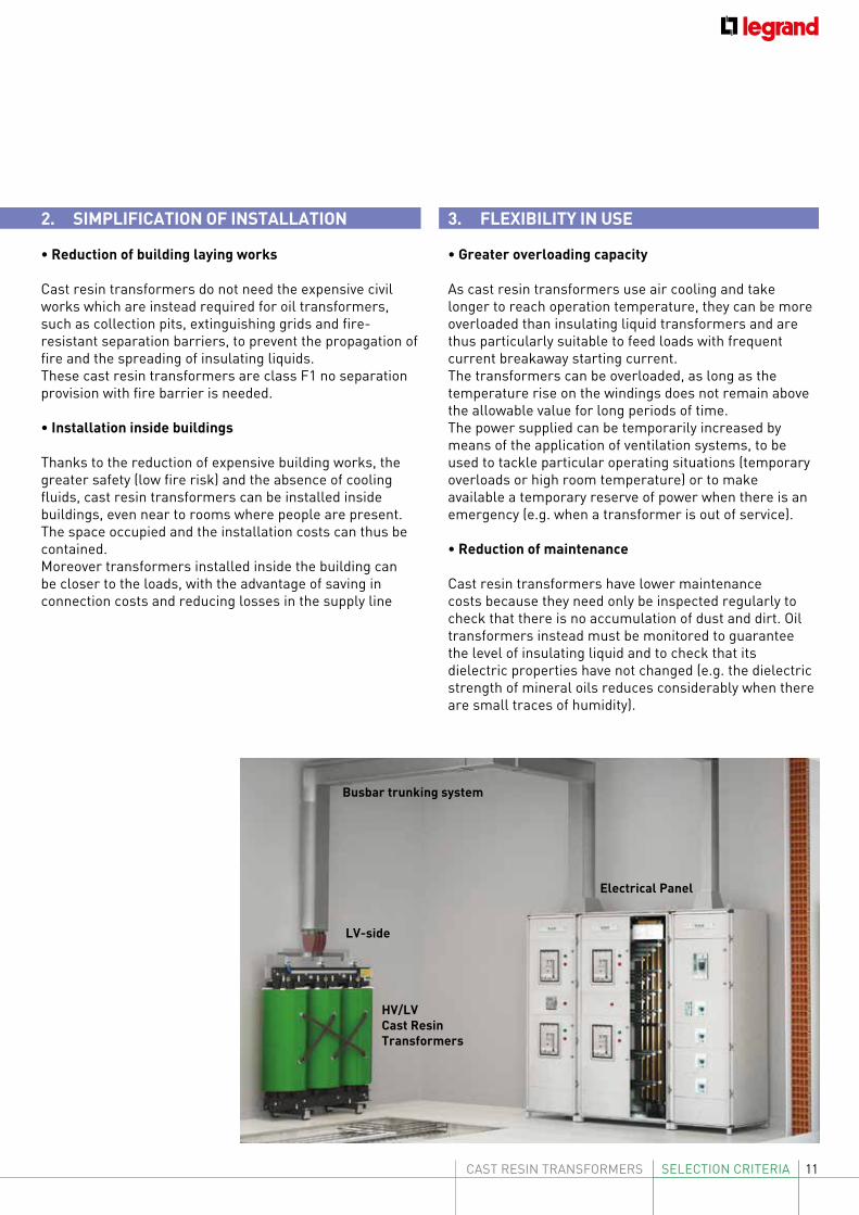
2. SIMPLIFICATION OF INSTALLATION
• Reduction of building laying works
Cast resin transformers do not need the expensive civil works which are instead required for oil transformers, such as collection pits, extinguishing grids and fire-resistant separation barriers, to prevent the propagation of fire and the spreading of insulating liquids. These cast resin transformers are class F1 no separation provision with fire barrier is needed.
• Installation inside buildings
Thanks to the reduction of expensive building works, the greater safety (low fire risk) and the absence of cooling fluids, cast resin transformers can be installed inside buildings, even near to rooms where people are present.The space occupied and the installation costs can thus be contained.Moreover transformers installed inside the building can be closer to the loads, with the advantage of saving in connection costs and reducing losses in the supply line
3. FLEXIBILITY IN USE
• Greater overloading capacity
As cast resin transformers use air cooling and take longer to reach operation temperature, they can be more overloaded than insulating liquid transformers and are thus particularly suitable to feed loads with frequent current breakaway starting current. The transformers can be overloaded, as long as the temperature rise on the windings does not remain above the allowable value for long periods of time. The power supplied can be temporarily increased by means of the application of ventilation systems, to be used to tackle particular operating situations (temporary overloads or high room temperature) or to make available a temporary reserve of power when there is an emergency (e.g. when a transformer is out of service).
• Reduction of maintenance
Cast resin transformers have lower maintenance costs because they need only be inspected regularly to check that there is no accumulation of dust and dirt. Oil transformers instead must be monitored to guarantee the level of insulating liquid and to check that its dielectric properties have not changed (e.g. the dielectric strength of mineral oils reduces considerably when there are small traces of humidity).
LV-side
HV/LV Cast Resin Transformers
Busbar trunking system
Electrical Panel
12
Economic advantages
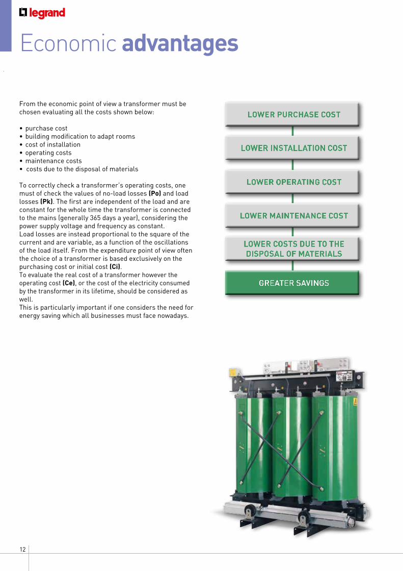
From the economic point of view a transformer must be chosen evaluating all the costs shown below:
• purchase cost• building modification to adapt rooms• cost of installation• operating costs• maintenance costs• costs due to the disposal of materials
To correctly check a transformer’s operating costs, one must of check the values of no-load losses (Po) and load losses (Pk). The first are independent of the load and are constant for the whole time the transformer is connected to the mains (generally 365 days a year), considering the power supply voltage and frequency as constant.Load losses are instead proportional to the square of the current and are variable, as a function of the oscillations of the load itself. From the expenditure point of view often the choice of a transformer is based exclusively on the purchasing cost or initial cost (Ci). To evaluate the real cost of a transformer however the operating cost (Ce), or the cost of the electricity consumed by the transformer in its lifetime, should be considered as well.This is particularly important if one considers the need for energy saving which all businesses must face nowadays.
LOWER PURCHASE COST
LOWER INSTALLATION COST
LOWER OPERATING COST
LOWER MAINTENANCE COST
LOWER COSTS DUE TO THE DISPOSAL OF MATERIALS
GREATER SAVINGS
13CAST RESIN TRANSFORMERS SELECTION CRITERIA
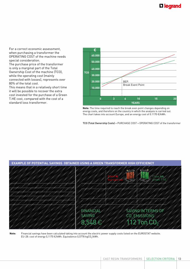
For a correct economic assessment, when purchasing a transformer the OPERATING COST of the machine needs special consideration.The purchase price of the transformer is only a marginal part of the Total Ownership Cost of the machine (TCO), while the operating cost (mainly connected with losses), represents over 80% of the total cost. This means that in a relatively short time it will be possible to recover the extra cost invested for the purchase of a Green T.HE cost, compared with the cost of a standard loss transformer.
Purchase price
Operating cost (20 years)
TOTAL Cost
Class N transformer
14,000 €
50,971 €
64,971 €
Class AAGreen T.HE
18,500 €
37,923 €
56,423 €
FINANCIAL SAVING
8,548 €
SAVING IN TERMS OF CO2 EMISSIONS
112 Ton CO2
In this example, the extra 4,500 € required for the purchase of the Green T.HE transformer is recovered in less than six years, while the total saving for the 20 year period will be approximately 8,500 €.
EUROPERated power (Sr): 1000 kVAPrimary no-load voltage (V10): 20 kVSecondary no-load voltage (V20): 400 VUk: 6%Transformer lifetime: 20 years
EXAMPLE OF POTENTIAL SAVINGS OBTAINED USING A GREEN TRANSFORMER HIGH EFFICIENCY
Note: Financial savings have been calculated taking into account the electric power supply costs listed on the EUROSTAT website. EU-28: cost of energy 0,1170 €/kWh. Equivalence 0,5778 kgCO2/kWh.
Note: The time required to reach the break even point changes depending on energy costs, and therefore on the country in which the analysis is carried out. The chart takes into account Europe, and an energy cost of 0.1170 €/kWh.
TCO (Total Ownership Costs) = PURCHASE COST + OPERATING COST of the transformer
0 3 6 10 15 20
60.000
50.000
40.000
30.000
20.000
10.000
TCO
YEARS
BEP.Break Event Point
€
14
CRT technology
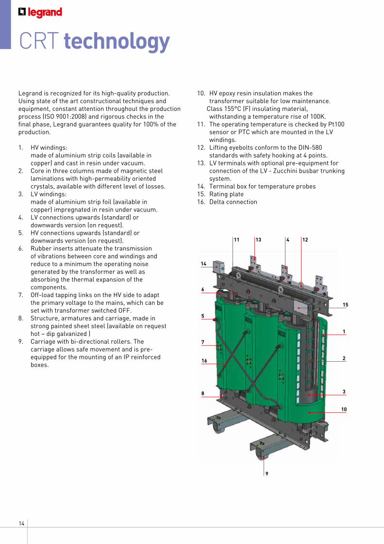
Legrand is recognized for its high-quality production. Using state of the art constructional techniques and equipment, constant attention throughout the production process (ISO 9001:2008) and rigorous checks in the final phase, Legrand guarantees quality for 100% of the production.
1. HV windings: made of aluminium strip coils (available in
copper) and cast in resin under vacuum.2. Core in three columns made of magnetic steel
laminations with high-permeability oriented crystals, available with different level of losses.
3. LV windings: made of aluminium strip foil (available in
copper) impregnated in resin under vacuum.4. LV connections upwards (standard) or
downwards version (on request).5. HV connections upwards (standard) or
downwards version (on request).6. Rubber inserts attenuate the transmission
of vibrations between core and windings and reduce to a minimum the operating noise generated by the transformer as well as absorbing the thermal expansion of the components.
7. Off-load tapping links on the HV side to adapt the primary voltage to the mains, which can be set with transformer switched OFF.
8. Structure, armatures and carriage, made in strong painted sheet steel (available on request hot – dip galvanized )
9. Carriage with bi-directional rollers. The carriage allows safe movement and is pre- equipped for the mounting of an IP reinforced boxes.
10. HV epoxy resin insulation makes the transformer suitable for low maintenance.
Class 155°C (F) insulating material, withstanding a temperature rise of 100K.
11. The operating temperature is checked by Pt100 sensor or PTC which are mounted in the LV windings.
12. Lifting eyebolts conform to the DIN-580 standards with safety hooking at 4 points.
13. LV terminals with optional pre-equipment for connection of the LV - Zucchini busbar trunking system.
14. Terminal box for temperature probes15. Rating plate16. Delta connection
5
7
8
6
1
2
3
10
9
11 13 4 12
16
14
15
15CAST RESIN TRANSFORMERS SELECTION CRITERIA
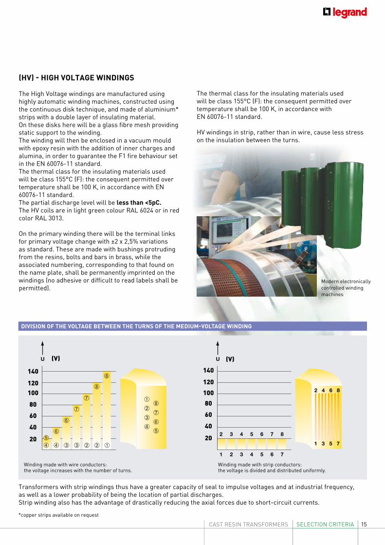
(HV) - HIGH VOLTAGE WINDINGS
The High Voltage windings are manufactured using highly automatic winding machines, constructed using the continuous disk technique, and made of aluminium* strips with a double layer of insulating material.On these disks here will be a glass fibre mesh providing static support to the winding. The winding will then be enclosed in a vacuum mould with epoxy resin with the addition of inner charges and alumina, in order to guarantee the F1 fire behaviour set in the EN 60076-11 standard.The thermal class for the insulating materials used will be class 155°C (F): the consequent permitted over temperature shall be 100 K, in accordance with EN 60076-11 standard.The partial discharge level will be less than <5pC. The HV coils are in light green colour RAL 6024 or in red color RAL 3013.
On the primary winding there will be the terminal links for primary voltage change with ±2 x 2,5% variations as standard. These are made with bushings protruding from the resins, bolts and bars in brass, while the associated numbering, corresponding to that found on the name plate, shall be permanently imprinted on the windings (no adhesive or difficult to read labels shall be permitted).
Modern electronically controlled winding machines
*copper strips available on request
Winding made with wire conductors: the voltage increases with the number of turns.
Winding made with strip conductors: the voltage is divided and distributed uniformly.
DIVISION OF THE VOLTAGE BETWEEN THE TURNS OF THE MEDIUM-VOLTAGE WINDING
➃
➄
➅
➆
➇
➃
➂
➁
➀
➅
➃➄
➅
➂
➆
➂
➆
➁
➇
➁
➇
➀
U
1 2 3 4 5 6 7
2 3 4 5 6 7 8
U
1
2
3
4
5
6
7
8
➃
➄
➅
➆
➇
➃
➂
➁
➀
➅
➃➄
➅
➂
➆
➂
➆
➁
➇
➁
➇
➀
U
1 2 3 4 5 6 7
2 3 4 5 6 7 8
U
1
2
3
4
5
6
7
8
Transformers with strip windings thus have a greater capacity of seal to impulse voltages and at industrial frequency, as well as a lower probability of being the location of partial discharges. Strip winding also has the advantage of drastically reducing the axial forces due to short-circuit currents.
(V) (V)
120
140
100
80
60
40
20
120
140
100
80
60
40
20
The thermal class for the insulating materials used will be class 155°C (F): the consequent permitted over temperature shall be 100 K, in accordance with EN 60076-11 standard.
HV windings in strip, rather than in wire, cause less stress on the insulation between the turns.
16
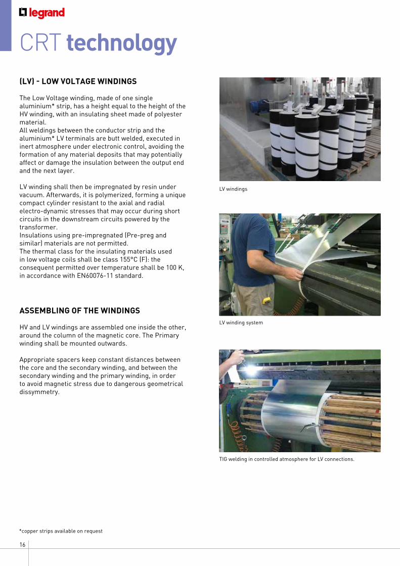
(LV) - LOW VOLTAGE WINDINGS
The Low Voltage winding, made of one single aluminium* strip, has a height equal to the height of the HV winding, with an insulating sheet made of polyester material.All weldings between the conductor strip and the aluminium* LV terminals are butt welded, executed in inert atmosphere under electronic control, avoiding the formation of any material deposits that may potentially affect or damage the insulation between the output end and the next layer.
LV winding shall then be impregnated by resin under vacuum. Afterwards, it is polymerized, forming a unique compact cylinder resistant to the axial and radial electro-dynamic stresses that may occur during short circuits in the downstream circuits powered by the transformer.Insulations using pre-impregnated (Pre-preg and similar) materials are not permitted. The thermal class for the insulating materials used in low voltage coils shall be class 155°C (F): the consequent permitted over temperature shall be 100 K, in accordance with EN60076-11 standard.
ASSEMBLING OF THE WINDINGS
HV and LV windings are assembled one inside the other, around the column of the magnetic core. The Primary winding shall be mounted outwards.
Appropriate spacers keep constant distances between the core and the secondary winding, and between the secondary winding and the primary winding, in order to avoid magnetic stress due to dangerous geometrical dissymmetry.
*copper strips available on request
TIG welding in controlled atmosphere for LV connections.
LV winding system
LV windings
CRT technology
17CAST RESIN TRANSFORMERS SELECTION CRITERIA
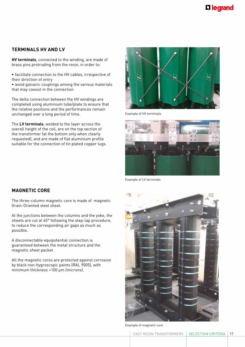
TERMINALS HV AND LV
HV terminals, connected to the winding, are made of brass pins protruding from the resin, in order to:
• facilitate connection to the HV cables, irrespective of their direction of entry• avoid galvanic couplings among the various materials that may coexist in the connection
The delta connection between the HV windings are completed using aluminium tube/plate to ensure that the relative positions and the performances remain unchanged over a long period of time.
The LV terminals, welded to the layer across the overall height of the coil, are on the top section of the transformer (at the bottom only when clearly requested), and are made of flat aluminium profile suitable for the connection of tin plated copper lugs.
MAGNETIC CORE
The three-column magnetic core is made of magnetic Grain-Oriented steel sheet.
At the junctions between the columns and the yoke, the sheets are cut at 45° following the step-lap procedure, to reduce the corresponding air gaps as much as possible.
A disconnectable equipotential connection is guaranteed between the metal structure and the magnetic sheet packet.
All the magnetic cores are protected against corrosion by black non-hygroscopic paints (RAL 9005), with minimum thickness >100 µm (microns).
Example of HV terminals
Example of LV terminals
Example of magnetic core
18
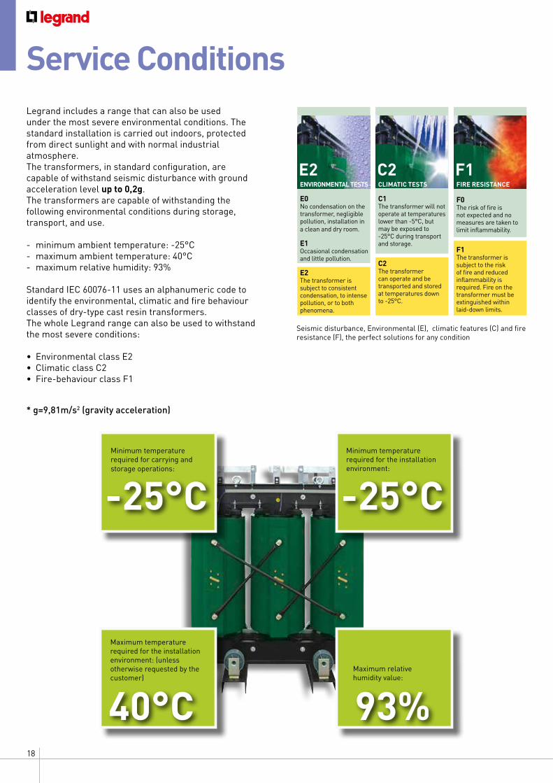
Legrand includes a range that can also be used under the most severe environmental conditions. The standard installation is carried out indoors, protected from direct sunlight and with normal industrial atmosphere.The transformers, in standard configuration, are capable of withstand seismic disturbance with ground acceleration level up to 0,2g.The transformers are capable of withstanding the following environmental conditions during storage, transport, and use.
- minimum ambient temperature: -25°C- maximum ambient temperature: 40°C- maximum relative humidity: 93%
Standard IEC 60076-11 uses an alphanumeric code to identify the environmental, climatic and fire behaviour classes of dry-type cast resin transformers. The whole Legrand range can also be used to withstand the most severe conditions:
• Environmental class E2 • Climatic class C2 • Fire-behaviour class F1
Service Conditions
Seismic disturbance, Environmental (E), climatic features (C) and fire resistance (F), the perfect solutions for any condition
-25°CMinimum temperature required for carrying and storage operations:
-25°CMinimum temperature required for the installation environment:
40°C
Maximum temperature required for the installation environment: (unless otherwise requested by the customer)
93%Maximum relative humidity value:
ENVIRONMENTAL TESTS
E0No condensation on the transformer, negligible pollution, installation in a clean and dry room.
E1 Occasional condensation and little pollution.
E2The transformer is subject to consistent condensation, to intense pollution, or to both phenomena.
CLIMATIC TESTS
C1 The transformer will not operate at temperatures lower than -5°C, but may be exposed to -25°C during transport and storage.
C2 The transformer can operate and be transported and stored at temperatures down to -25°C.
FIRE RESISTANCE
F0The risk of fire is not expected and no measures are taken to limit inflammability.
F1 The transformer is subject to the risk of fire and reduced inflammability is required. Fire on the transformer must be extinguished within laid-down limits.
E2 C2 F1
* g=9,81m/s2 (gravity acceleration)
19CAST RESIN TRANSFORMERS SELECTION CRITERIA
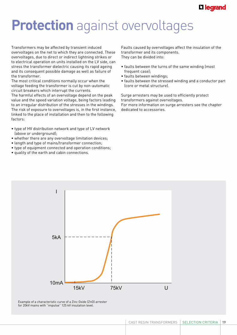
Transformers may be affected by transient induced overvoltages on the net to which they are connected. These overvoltages, due to direct or indirect lightning strikes or to electrical operation on units installed on the LV side, can stress the transformer dielectric causing its rapid ageing and its consequent possible damage as well as failure of the transformer.The most critical conditions normally occur when the voltage feeding the transformer is cut by non-automatic circuit breakers which interrupt the currents.The harmful effects of an overvoltage depend on the peak value and the speed variation voltage, being factors leading to an irregular distribution of the stresses in the windings. The risk of exposure to overvoltages is, in the first instance, linked to the place of installation and then to the following factors:
• type of HV distribution network and type of LV network (above or underground);
• whether there are any overvoltage limitation devices;• length and type of mains/transformer connection;• type of equipment connected and operation conditions;• quality of the earth and cabin connections.
Protection against overvoltages Faults caused by overvoltages affect the insulation of the transformer and its components. They can be divided into:
• faults between the turns of the same winding (most frequent case);
• faults between windings;• faults between the stressed winding and a conductor part
(core or metal structure).
Surge arresters may be used to efficiently protect transformers against overvoltages.For more information on surge arresters see the chapter dedicated to accessories.
Example of a characteristic curve of a Zinc Oxide (ZnO) arrester for 20kV mains with “impulse” 125 kV insulation level.
I
5kA
10mA15kV 75kV U
10Ir
5Ir
2Ir
Ir
5s 20s 2mn 10mn 1h 5h t 10s 1mn 5mn 20mn 2h
20
During its normal operation a transformer has no-load losses and load losses which generate thermal energy. This energy depends on the construction of the transformer, its power and the installation conditions. It should be remembered that the transfer of thermal energy is proportional to the temperature difference between the transformer and the room (ambient). At a given room temperature, the transformer temperature depends mainly on the load losses. As the load increases, losses and room temperature increase favouring a more rapid degradation of the insulation materials and thus a higher probability of failure of the dielectric. This situation could also occur when, with equal losses due to load, the room temperature and consequently the transformer temperature increase. The standards define insulation classes indicate the maximum temperatures which can be reached by the transformers in their normal operation and which must not be exceeded.Temperature rises depend not only on the load and the overcurrents which may be detected by the protection devices, but also on environmental factors (inefficiency of the cooling system, fault on the forced ventilation and increase of the room temperature) which influence the dissipation of heat produced by the transformer’s losses. For this reason, electronic temperature measuring devices are normally provided. These are necessary to give the alarm or to trigger the transformer protection. For LEGRAND transformers the following temperature sensors are available:Pt100 thermosensors and PTC thermistors.
• Pt100: supplies a signal proportional to the measured temperature;• PTC: supplies an ON/OFF signal depending on whether the measured temperature is less or more than the sensor’s threshold.The sensors are positioned in the hot point of the winding. Both the Pt100 and PTC signals must be processed by the temperature control unit, which is not part of the standard equipment.On request, other accessories to check the temperature are available:
• a separate temperature display, to be installed on the control panel;• an output relay for alarm and trip and control of the fans.
Protection against temperature rise
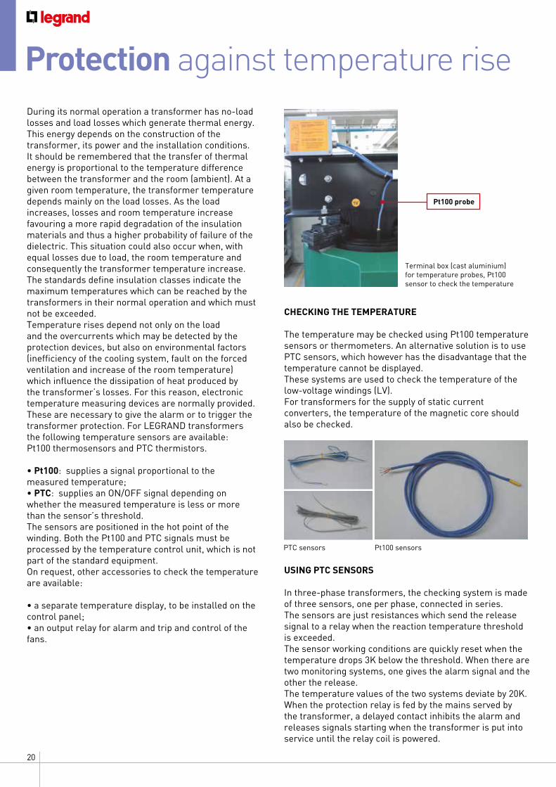
Terminal box (cast aluminium) for temperature probes, Pt100 sensor to check the temperature
CHECKING THE TEMPERATURE
The temperature may be checked using Pt100 temperature sensors or thermometers. An alternative solution is to use PTC sensors, which however has the disadvantage that the temperature cannot be displayed.These systems are used to check the temperature of the low-voltage windings (LV).For transformers for the supply of static current converters, the temperature of the magnetic core should also be checked.
USING PTC SENSORS
In three-phase transformers, the checking system is made of three sensors, one per phase, connected in series. The sensors are just resistances which send the release signal to a relay when the reaction temperature threshold is exceeded. The sensor working conditions are quickly reset when the temperature drops 3K below the threshold. When there are two monitoring systems, one gives the alarm signal and the other the release. The temperature values of the two systems deviate by 20K. When the protection relay is fed by the mains served by the transformer, a delayed contact inhibits the alarm and releases signals starting when the transformer is put into service until the relay coil is powered.
PTC sensors Pt100 sensors
Pt100 probe
21CAST RESIN TRANSFORMERS SELECTION CRITERIA
Ventilation of the Transformers
pg
pg
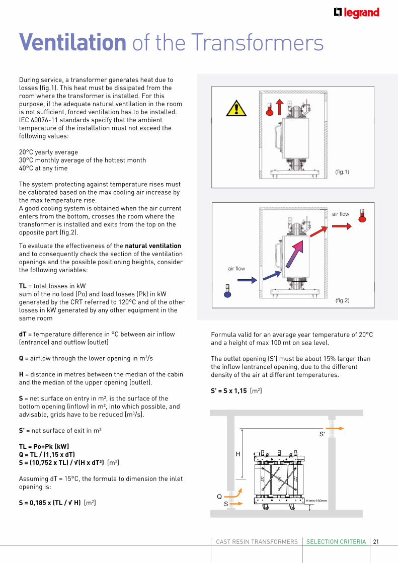
During service, a transformer generates heat due to losses (fig.1). This heat must be dissipated from the room where the transformer is installed. For this purpose, if the adequate natural ventilation in the room is not sufficient, forced ventilation has to be installed.IEC 60076-11 standards specify that the ambient temperature of the installation must not exceed the following values:
20°C yearly average30°C monthly average of the hottest month40°C at any time
The system protecting against temperature rises must be calibrated based on the max cooling air increase by the max temperature rise. A good cooling system is obtained when the air current enters from the bottom, crosses the room where the transformer is installed and exits from the top on the opposite part (fig.2).
To evaluate the effectiveness of the natural ventilation and to consequently check the section of the ventilation openings and the possible positioning heights, consider the following variables:
TL = total losses in kWsum of the no load (Po) and load losses (Pk) in kW generated by the CRT referred to 120°C and of the other losses in kW generated by any other equipment in the same room
dT = temperature difference in °C between air inflow (entrance) and outflow (outlet)
Q = airflow through the lower opening in m3/s
H = distance in metres between the median of the cabin and the median of the upper opening (outlet).
S = net surface on entry in m², is the surface of the bottom opening (inflow) in m², into which possible, and advisable, grids have to be reduced [m3/s].
S’ = net surface of exit in m²
TL = Po+Pk [kW]Q = TL / (1,15 x dT)S = (10,752 x TL) / √(H x dT³) [m2]
Assuming dT = 15°C, the formula to dimension the inlet opening is:
S = 0,185 x (TL / √ H) [m2]
Formula valid for an average year temperature of 20°C and a height of max 100 mt on sea level.
The outlet opening (S’) must be about 15% larger than the inflow (entrance) opening, due to the different density of the air at different temperatures.
S’ = S x 1,15 [m2]
(fig.1)
(fig.2)
air flow
air flow
SQ
S'
H
H min:160mm
S
S'
H
H min:160mm
22
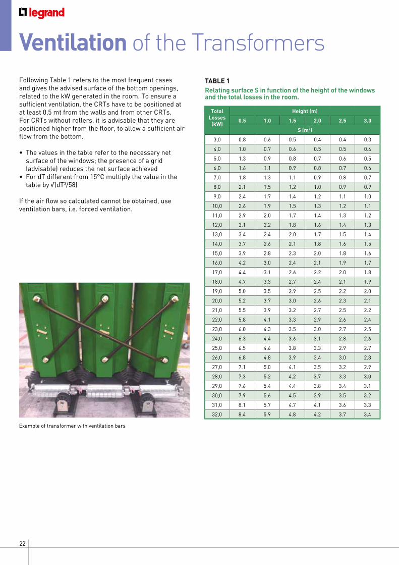
Ventilation of the Transformers Following Table 1 refers to the most frequent cases and gives the advised surface of the bottom openings, related to the kW generated in the room. To ensure a sufficient ventilation, the CRTs have to be positioned at at least 0,5 mt from the walls and from other CRTs. For CRTs without rollers, it is advisable that they are positioned higher from the floor, to allow a sufficient air flow from the bottom.
• The values in the table refer to the necessary net surface of the windows; the presence of a grid (advisable) reduces the net surface achieved
• For dT different from 15°C multiply the value in the table by √(dT³/58)
If the air flow so calculated cannot be obtained, use ventilation bars, i.e. forced ventilation.
Total Losses
(kW)
Height (m)
0.5 1.0 1.5 2.0 2.5 3.0
S (m2)
3,0 0.8 0.6 0.5 0.4 0.4 0.3
4,0 1.0 0.7 0.6 0.5 0.5 0.4
5,0 1.3 0.9 0.8 0.7 0.6 0.5
6,0 1.6 1.1 0.9 0.8 0.7 0.6
7,0 1.8 1.3 1.1 0.9 0.8 0.7
8,0 2.1 1.5 1.2 1.0 0.9 0.9
9,0 2.4 1.7 1.4 1.2 1.1 1.0
10,0 2.6 1.9 1.5 1.3 1.2 1.1
11,0 2.9 2.0 1.7 1.4 1.3 1.2
12,0 3.1 2.2 1.8 1.6 1.4 1.3
13,0 3.4 2.4 2.0 1.7 1.5 1.4
14,0 3.7 2.6 2.1 1.8 1.6 1.5
15,0 3.9 2.8 2.3 2.0 1.8 1.6
16,0 4.2 3.0 2.4 2.1 1.9 1.7
17,0 4.4 3.1 2.6 2.2 2.0 1.8
18,0 4.7 3.3 2.7 2.4 2.1 1.9
19,0 5.0 3.5 2.9 2.5 2.2 2.0
20,0 5.2 3.7 3.0 2.6 2.3 2.1
21,0 5.5 3.9 3.2 2.7 2.5 2.2
22,0 5.8 4.1 3.3 2.9 2.6 2.4
23,0 6.0 4.3 3.5 3.0 2.7 2.5
24,0 6.3 4.4 3.6 3.1 2.8 2.6
25,0 6.5 4.6 3.8 3.3 2.9 2.7
26,0 6.8 4.8 3.9 3.4 3.0 2.8
27,0 7.1 5.0 4.1 3.5 3.2 2.9
28,0 7.3 5.2 4.2 3.7 3.3 3.0
29,0 7.6 5.4 4.4 3.8 3.4 3.1
30,0 7.9 5.6 4.5 3.9 3.5 3.2
31,0 8.1 5.7 4.7 4.1 3.6 3.3
32,0 8.4 5.9 4.8 4.2 3.7 3.4
TABLE 1 Relating surface S in function of the height of the windows and the total losses in the room.
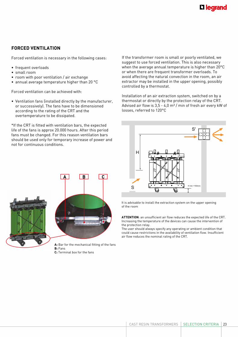
Example of transformer with ventilation bars
23CAST RESIN TRANSFORMERS SELECTION CRITERIA
H min =160mm
SQ
S'
H
H min =160mm
S
S'
H
ATTENTION: an unsufficient air flow reduces the expected life of the CRT. Increasing the temperature of the devices can cause the intervention of the protection relay.The user should always specify any operating or ambient condition that could cause restrictions in the availability of ventilation flow. Insufficient air flow reduces the nominal rating of the CRT.
A: Bar for the mechanical fitting of the fans B: FansC: Terminal box for the fans
It is advisable to install the extraction system on the upper opening of the room
FORCED VENTILATION
Forced ventilation is necessary in the following cases:
• frequent overloads • small room • room with poor ventilation / air exchange • annual average temperature higher than 20 °C
Forced ventilation can be achieved with:
• Ventilation fans (installed directly by the manufacturer, or successively). The fans have to be dimensioned according to the rating of the CRT and the overtemperature to be dissipated.
*If the CRT is fitted with ventilation bars, the expected life of the fans is approx 20.000 hours. After this period fans must be changed. For this reason ventilation bars should be used only for temporary increase of power and not for continuous conditions.
If the transformer room is small or poorly ventilated, we suggest to use forced ventilation. This is also necessary when the average annual temperature is higher than 20°C or when there are frequent transformer overloads. To avoid affecting the natural convection in the room, an air extractor may be installed in the upper opening, possibly controlled by a thermostat.
Installation of an air extraction system, switched on by a thermostat or directly by the protection relay of the CRT. Advised air flow is 3,5 - 4,0 m³ / min of fresh air every kW of losses, referred to 120°C
A B C
GENERAL FEATURES24
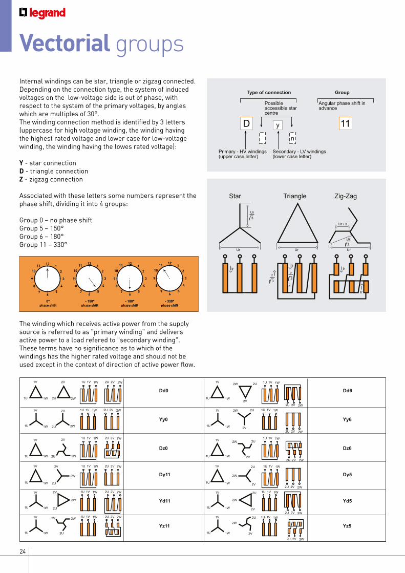
Internal windings can be star, triangle or zigzag connected. Depending on the connection type, the system of induced voltages on the low-voltage side is out of phase, with respect to the system of the primary voltages, by angles which are multiples of 30°. The winding connection method is identified by 3 letters (uppercase for high voltage winding, the winding having the highest rated voltage and lower case for low-voltage winding, the winding having the lowes rated voltage):
Y - star connectionD - triangle connectionZ - zigzag connection
Associated with these letters some numbers represent the phase shift, dividing it into 4 groups:
Group 0 – no phase shiftGroup 5 – 150°Group 6 – 180°Group 11 – 330°
The winding which receives active power from the supply source is referred to as "primary winding" and delivers active power to a load refered to "secondary winding". These terms have no significance as to which of the windings has the higher rated voltage and should not be used except in the context of direction of active power flow.
Vectorial groups
1W
1W
1W
1W
1W
1W
1U
1U
1U
1U 1U
1U
1U
1V
1V
1V
1V 1V
1V
1V
1W
1W
1W
1W
1W
1W
1U
1U
1U
1U
1U
1V
1V
1V
1V
1V
2W
2W
2W
2W
2W
2W
2W
2W
2W
2W
2W
2W
2U
2U
2U
2U
2U
2U
2U
2U
2U
2U
2U
2U
2V
2V
2V
2V
2V
2V
2V
2V
2V
2V
2V
2V
Dd0
1W1U 1V 1W1U 1V
1W1U 1V
1W1U 1V
1W1U 1V
1W1U 1V
1W1U 1V
2W2U 2V
2W2U 2V
2W2U 2V
2W2U 2V
2W2U 2V
2W2U 2V
2W2U 2V
1W1U 1V 2W2U 2V
1W1U 1V 2W2U 2V
1W1U 1V 2W2U 2V
1W1U 1V 2W2U 2V
1W1U 1V 2W2U 2V
Yy0
Dz0
Dy11
Yd11
Yz11
Dd6
Yy6
Dz6
Yz5
Yd5
Dy5
Ur
Ur 3
Ur, I3
Zig-Zag
Ir
Ir
Ur
Triangle
Ir
Ir 3
Ir 3
Ur
Ur 3
Star
Ir
D y
n
Type of connection
Possible accessible star centre
Primary - HV windings (upper case letter)
Secondary - LV windings (lower case letter)
Group
Angular phase shift in advance
11
Ur
Ur 3
Ur / 3
Zig-Zag
Ir
Ir
Ur
Triangle
Ir
Ir 3
Ir 3
Ur
Ur 3
Star
Ir
D y
n
Type of connection
Possible accessible star centre
Primary windings (upper case letter)
Secondary windings (lower case letter)
Group
Angular phase shift in advance
11
121
2
3
4
56
7
8
9
1011
121
2
3
4
56
7
8
9
1011 12
1
2
3
4
56
7
8
9
1011
121
2
3
4
56
7
8
9
1011
0°phase shift
- 150°phase shift
- 180°phase shift
- 330°phase shift
25CAST RESIN TRANSFORMERS GENERAL FEATURES
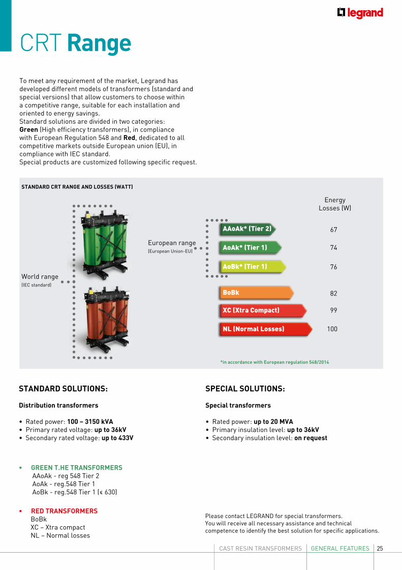
CRT RangeTo meet any requirement of the market, Legrand has developed different models of transformers (standard and special versions) that allow customers to choose within a competitive range, suitable for each installation and oriented to energy savings.Standard solutions are divided in two categories:Green (High efficiency transformers), in compliance with European Regulation 548 and Red, dedicated to all competitive markets outside European union (EU), in compliance with IEC standard.Special products are customized following specific request.
74
76
82
99
100
EnergyLosses (W)
World range (IEC standard)
European range(European Union-EU)
*in accordance with European regulation 548/2014
STANDARD CRT RANGE AND LOSSES (WATT)
67
AoAk* (Tier 1)
AoBk* (Tier 1)
BoBk
XC (Xtra Compact)
NL (Normal Losses)
AAoAk* (Tier 2)
STANDARD SOLUTIONS:
Distribution transformers
• Rated power: 100 – 3150 kVA• Primary rated voltage: up to 36kV• Secondary rated voltage: up to 433V
• GREEN T.HE TRANSFORMERS AAoAk - reg 548 Tier 2 AoAk - reg.548 Tier 1 AoBk - reg.548 Tier 1 (≤ 630) • RED TRANSFORMERS BoBk XC – Xtra compact NL – Normal losses
SPECIAL SOLUTIONS:
Special transformers
• Rated power: up to 20 MVA• Primary insulation level: up to 36kV• Secondary insulation level: on request
Please contact LEGRAND for special transformers.You will receive all necessary assistance and technical competence to identify the best solution for specific applications.
26 GENERAL FEATURES
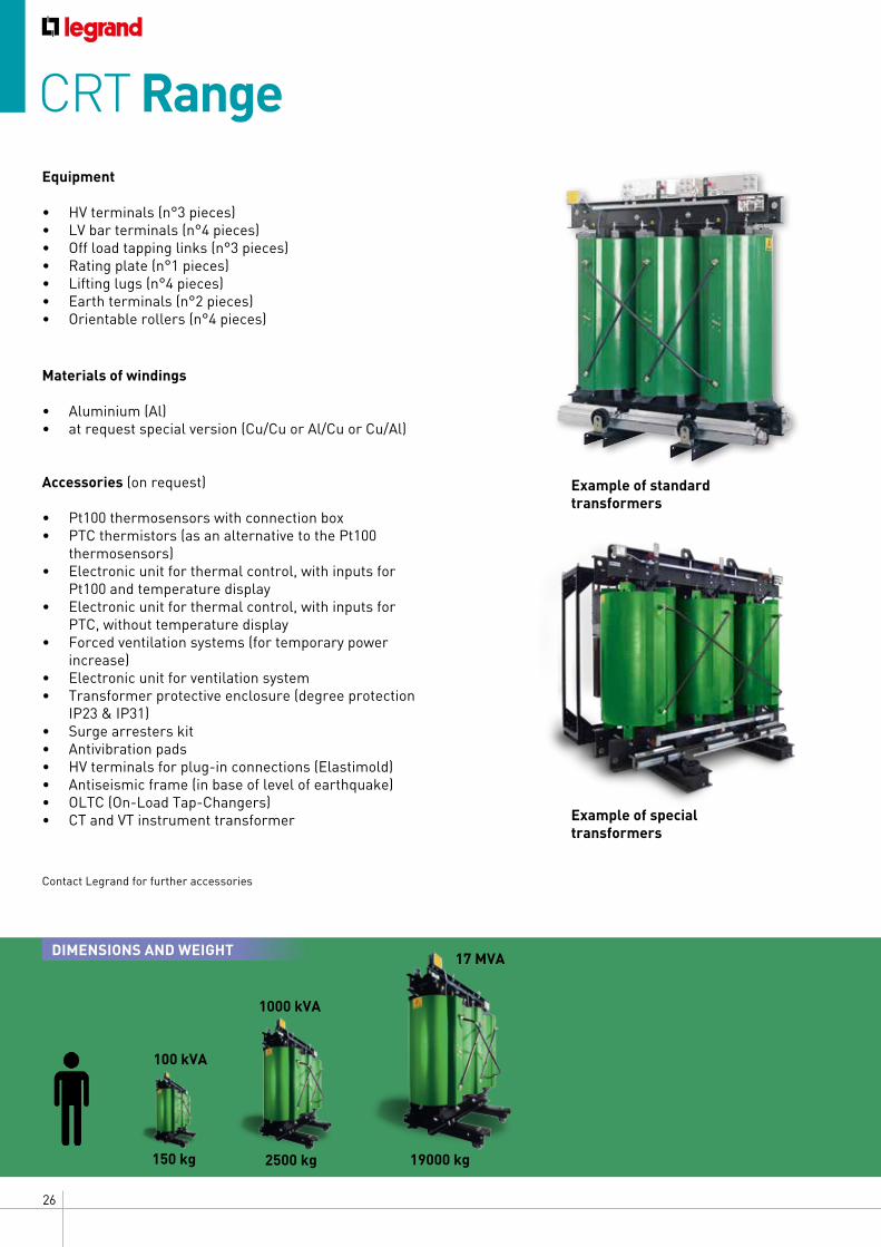
CRT Range
DIMENSIONS AND WEIGHT
100 kVA
1000 kVA
17 MVA
150 kg 2500 kg 19000 kg
Equipment
• HV terminals (n°3 pieces)• LV bar terminals (n°4 pieces)• Off load tapping links (n°3 pieces)• Rating plate (n°1 pieces)• Lifting lugs (n°4 pieces)• Earth terminals (n°2 pieces)• Orientable rollers (n°4 pieces)
Contact Legrand for further accessories
Materials of windings
• Aluminium (Al)• at request special version (Cu/Cu or Al/Cu or Cu/Al)
Accessories (on request)
• Pt100 thermosensors with connection box• PTC thermistors (as an alternative to the Pt100
thermosensors)• Electronic unit for thermal control, with inputs for
Pt100 and temperature display• Electronic unit for thermal control, with inputs for
PTC, without temperature display• Forced ventilation systems (for temporary power
increase)• Electronic unit for ventilation system• Transformer protective enclosure (degree protection
IP23 & IP31) • Surge arresters kit• Antivibration pads• HV terminals for plug-in connections (Elastimold)• Antiseismic frame (in base of level of earthquake)• OLTC (On-Load Tap-Changers)• CT and VT instrument transformer Example of special
transformers
Example of standard transformers
27CAST RESIN TRANSFORMERS GENERAL FEATURES
Green T.HE standard solutions for European market
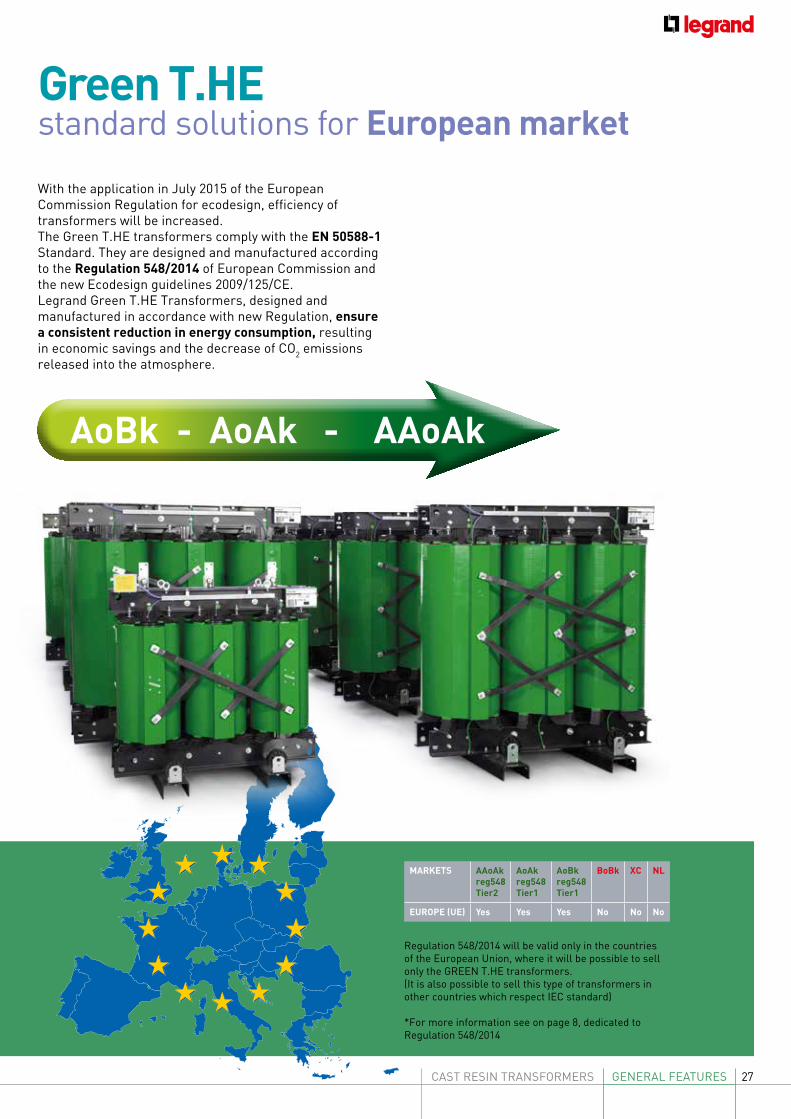
With the application in July 2015 of the European Commission Regulation for ecodesign, efficiency of transformers will be increased.The Green T.HE transformers comply with the EN 50588-1 Standard. They are designed and manufactured according to the Regulation 548/2014 of European Commission and the new Ecodesign guidelines 2009/125/CE.Legrand Green T.HE Transformers, designed and manufactured in accordance with new Regulation, ensure a consistent reduction in energy consumption, resulting in economic savings and the decrease of CO2 emissions released into the atmosphere.
Regulation 548/2014 will be valid only in the countries of the European Union, where it will be possible to sell only the GREEN T.HE transformers.(It is also possible to sell this type of transformers in other countries which respect IEC standard)
*For more information see on page 8, dedicated to Regulation 548/2014
AoBk - AoAk - AAoAk
MARKETS AAoAk reg548Tier2
AoAk reg548Tier1
AoBkreg548Tier1
BoBk XC NL
EUROPE (UE) Yes Yes Yes No No No
28 GENERAL FEATURES
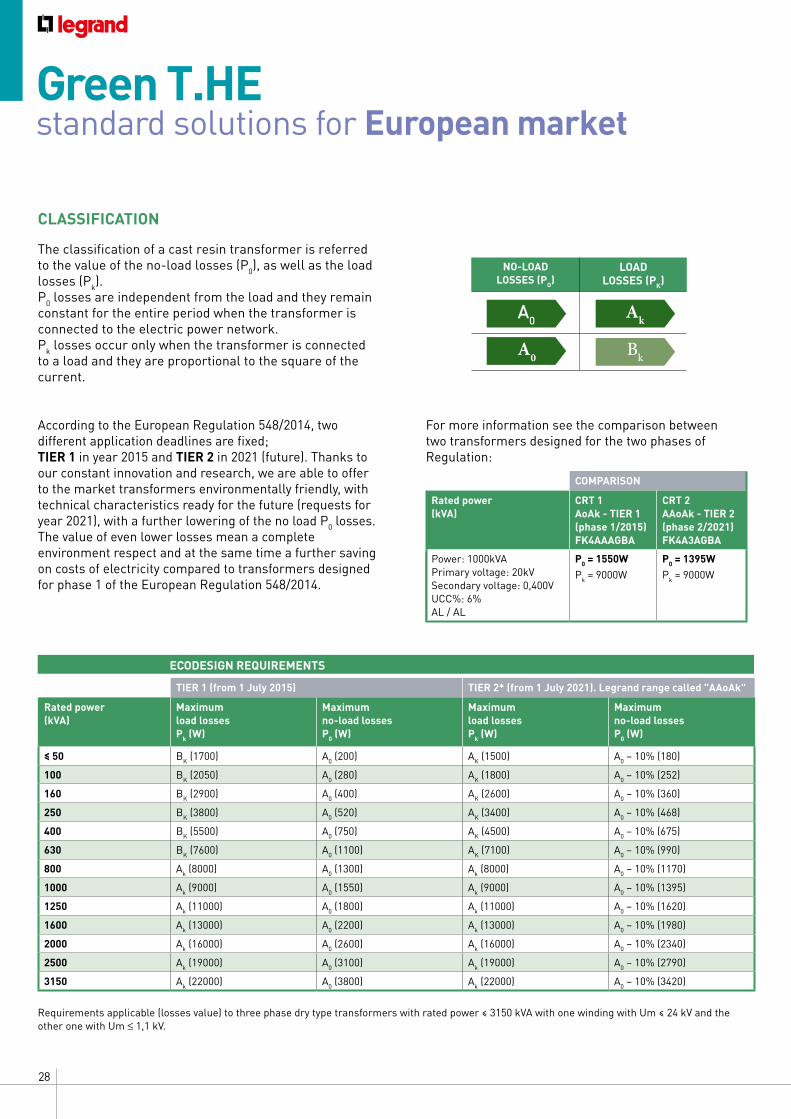
Requirements applicable (losses value) to three phase dry type transformers with rated power ≤ 3150 kVA with one winding with Um ≤ 24 kV and the other one with Um ≤ 1,1 kV.
Green T.HE standard solutions for European market
For more information see the comparison between two transformers designed for the two phases of Regulation:
COMPARISON
Rated power(kVA)
CRT 1AoAk - TIER 1(phase 1/2015) FK4AAAGBA
CRT 2AAoAk - TIER 2(phase 2/2021) FK4A3AGBA
Power: 1000kVAPrimary voltage: 20kVSecondary voltage: 0,400VUCC%: 6%AL / AL
P0 = 1550WPk = 9000W
P0 = 1395WPk = 9000W
According to the European Regulation 548/2014, two different application deadlines are fixed;TIER 1 in year 2015 and TIER 2 in 2021 (future). Thanks to our constant innovation and research, we are able to offer to the market transformers environmentally friendly, with technical characteristics ready for the future (requests for year 2021), with a further lowering of the no load P0 losses.The value of even lower losses mean a complete environment respect and at the same time a further saving on costs of electricity compared to transformers designed for phase 1 of the European Regulation 548/2014.
CLASSIFICATION
The classification of a cast resin transformer is referred to the value of the no-load losses (P0), as well as the load losses (Pk). P0 losses are independent from the load and they remain constant for the entire period when the transformer is connected to the electric power network. Pk losses occur only when the transformer is connected to a load and they are proportional to the square of the current.
NO-LOADLOSSES (PO)
LOADLOSSES (PK)
A0 Ak
A0 Bk
TIER 1 (from 1 July 2015) TIER 2* (from 1 July 2021). Legrand range called "AAoAk"
Rated power(kVA)
Maximum load lossesPk (W)
Maximum no-load losses P0 (W)
Maximum load lossesPk (W)
Maximum no-load lossesP0 (W)
≤ 50 BK (1700) A0 (200) AK (1500) A0 – 10% (180)
100 BK (2050) A0 (280) AK (1800) A0 – 10% (252)
160 BK (2900) A0 (400) AK (2600) A0 – 10% (360)
250 BK (3800) A0 (520) AK (3400) A0 – 10% (468)
400 BK (5500) A0 (750) AK (4500) A0 – 10% (675)
630 BK (7600) A0 (1100) AK (7100) A0 – 10% (990)
800 Ak (8000) A0 (1300) Ak (8000) A0 – 10% (1170)
1000 Ak (9000) A0 (1550) Ak (9000) A0 – 10% (1395)
1250 Ak (11000) A0 (1800) Ak (11000) A0 – 10% (1620)
1600 Ak (13000) A0 (2200) Ak (13000) A0 – 10% (1980)
2000 Ak (16000) A0 (2600) Ak (16000) A0 – 10% (2340)
2500 Ak (19000) A0 (3100) Ak (19000) A0 – 10% (2790)
3150 Ak (22000) A0 (3800) Ak (22000) A0 – 10% (3420)
ECODESIGN REQUIREMENTS
29CAST RESIN TRANSFORMERS GENERAL FEATURES
S A V
I N
G
TYPE OF THE PARTIAL DISCHARGES
Depending on the type, discharges can be divided into:
Corona effect: is the discharge that happen in air or in a gas surrounding a conductor, this usually occurs in relation to points and edges present on the conductors.
Surface discharges: it occurs on the surface of an insulator and which generally causes damage on the surface of the insulation itself, reducing the efficiency
Internal discharges: represents the main cause of life-cycle decrease of the insulating material)
Treeing (branched discharge channel): is the channel of pre-discharge which is formed following the degradation of the insulation and which leads to a destructive discharge.
LOW, PARTIAL DISCHARGES, HIGH QUALITY
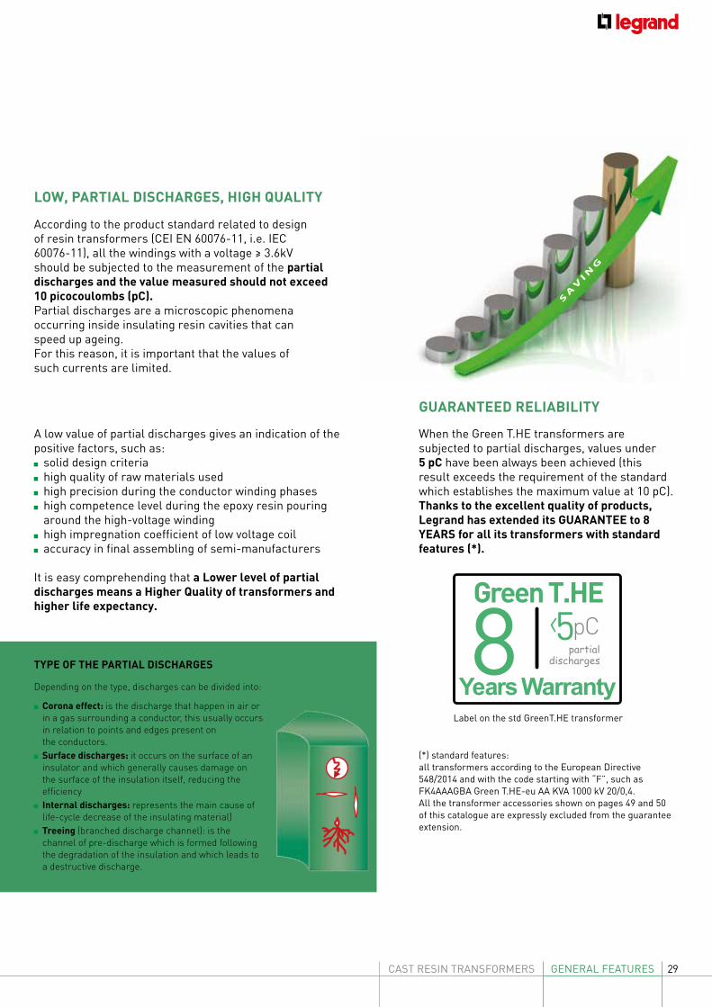
According to the product standard related to design of resin transformers (CEI EN 60076-11, i.e. IEC 60076-11), all the windings with a voltage ≥ 3.6kV should be subjected to the measurement of the partial discharges and the value measured should not exceed 10 picocoulombs (pC).Partial discharges are a microscopic phenomena occurring inside insulating resin cavities that can speed up ageing.For this reason, it is important that the values ofsuch currents are limited.
A low value of partial discharges gives an indication of the positive factors, such as: solid design criteria high quality of raw materials used high precision during the conductor winding phases high competence level during the epoxy resin pouring around the high-voltage winding
high impregnation coefficient of low voltage coil accuracy in final assembling of semi-manufacturers
It is easy comprehending that a Lower level of partial discharges means a Higher Quality of transformers and higher life expectancy.
When the Green T.HE transformers are subjected to partial discharges, values under 5 pC have been always been achieved (this result exceeds the requirement of the standard which establishes the maximum value at 10 pC).Thanks to the excellent quality of products, Legrand has extended its GUARANTEE to 8 YEARS for all its transformers with standard features (*).
GUARANTEED RELIABILITY
Label on the std GreenT.HE transformer
Green T.HE
8Years Warranty
partialdischarges
pC5
(*) standard features:all transformers according to the European Directive 548/2014 and with the code starting with “F”, such as FK4AAAGBA Green T.HE-eu AA KVA 1000 kV 20/0,4.All the transformer accessories shown on pages 49 and 50 of this catalogue are expressly excluded from the guarantee extension.
30 GENERAL FEATURES
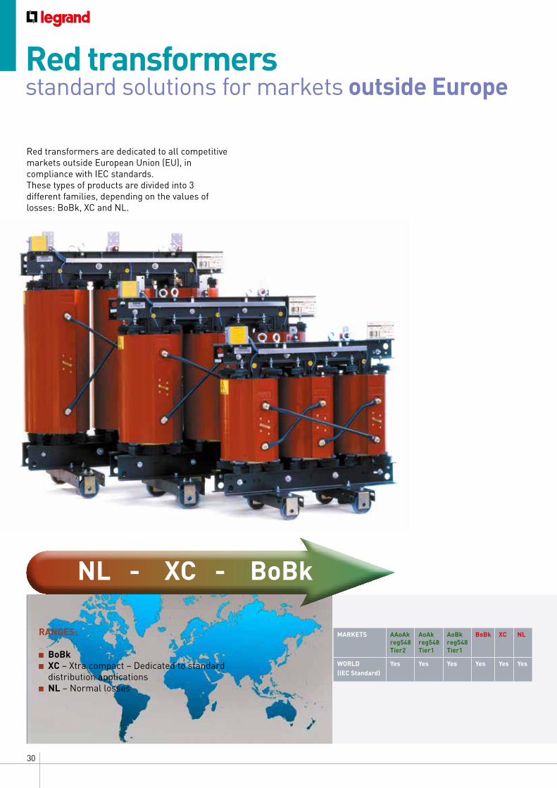
RANGES:
BoBk XC – Xtra compact – Dedicated to standard distribution applications
NL – Normal losses
Red transformers standard solutions for markets outside Europe
Red transformers are dedicated to all competitive markets outside European Union (EU), in compliance with IEC standards.These types of products are divided into 3 different families, depending on the values of losses: BoBk, XC and NL.
MARKETS AAoAk reg548Tier2
AoAk reg548Tier1
AoBkreg548Tier1
BoBk XC NL
WORLD (IEC Standard)
Yes Yes Yes Yes Yes Yes
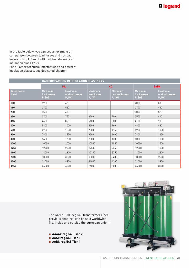
NL - XC - BoBk
31CAST RESIN TRANSFORMERS GENERAL FEATURES
NL XC BoBkRated power(kVA)
Maximum load lossesPk (W)
Maximum no-load losses P0 (W)
Maximum load lossesPk (W)
Maximum no-load losses P0 (W)
Maximum load lossesPk (W)
Maximum no-load lossesP0 (W)
100 1900 420 2000 330
160 2700 550 2700 450
200 3500 680 3050 520
250 3700 750 4200 700 3500 610
315 4600 850 5100 800 4100 730
400 5400 1000 5500 960 4900 880
500 6700 1200 7000 1150 5950 1000
630 7600 1450 8200 1400 7300 1150
800 9400 1750 9300 1700 9000 1300
1000 10000 2000 10500 1950 10000 1500
1250 12700 2300 12500 2350 12000 1800
1600 14000 2800 15300 2750 14500 2200
2000 18000 3300 18800 3400 18000 2600
2500 21000 4300 21000 4200 21000 3200
3150 26000 4600 26000 5000 26000 3800
LOAD COMPARISON IN INSULATION CLASS 12 kV
The Green T.HE reg 548 transformers (see previous chapter), can be sold worldwide (i.e. inside and outside the european union):
AAoAk reg.548 Tier 2 AoAk reg.548 Tier 1 AoBk reg.548 Tier 1
In the table below, you can see an example ofcomparison between load losses and no-loadlosses of NL, XC and BoBk red transformers in insulation class 12 kV.For all other technical informations and different insulation classes, see dedicated chapter.
32 GENERAL FEATURES
TECHNICAL CHARACTERISTICS Modern cruise ships and high tech ships use electric propulsion systems that require special transformers to cope with strict on-board technical requirements such as reduced noise and vibration levels, limited space, reduced maintenance system, high resistance to the corrosive action of sea water and sea air, and a high degree of security to avoid risk to humans.
Legrand cast resin transformers and reactors for marine applications are designed and manufactured according to the highest International Standards and are approved by the most stringent certification bodies.
Our design, production and control procedures are certified by ISO 9001:2008 (Bureau Veritas). This allows us to offer to the customer a reliable product in terms of quality, safety and performance. Moreover, thanks to our specialism in the production of cast resin transformers, we are able to design reliable solutions that meet the exact needs of our customers.
Our products are suitable for specialist applications, particularly in petrochemical and gas environments.
MAIN FEATURES optimised design based on specific harmonic loads compact dimensions, lightweight materials designs can be adapted to the dimensional constraints of any installation
specific cooling enclosure rated power: max 20 MVA; insulation levels: max 36 kV; frequency: 50 or 60 Hz; degree of protection: max IP55; standard colour (UK): RAL 7035 (color available on request); cooling system: AN (Natural Air), AN / AF
(natural air/forced air) or AF / WF (forced air/forced water); constructive configuration for each
transformer: max 24 pulse;
WORKING CONDITIONS: good resistance to humid and salty environments heavy-duty use, working even in the presence of vibrations and considerable mechanical stresses
meeting the most stringent Standards and specifications
Custom transformers are also available and can be equipped with temperature, current and voltage control systems, PreMag transformers, antivibration devices and IR temperature control.
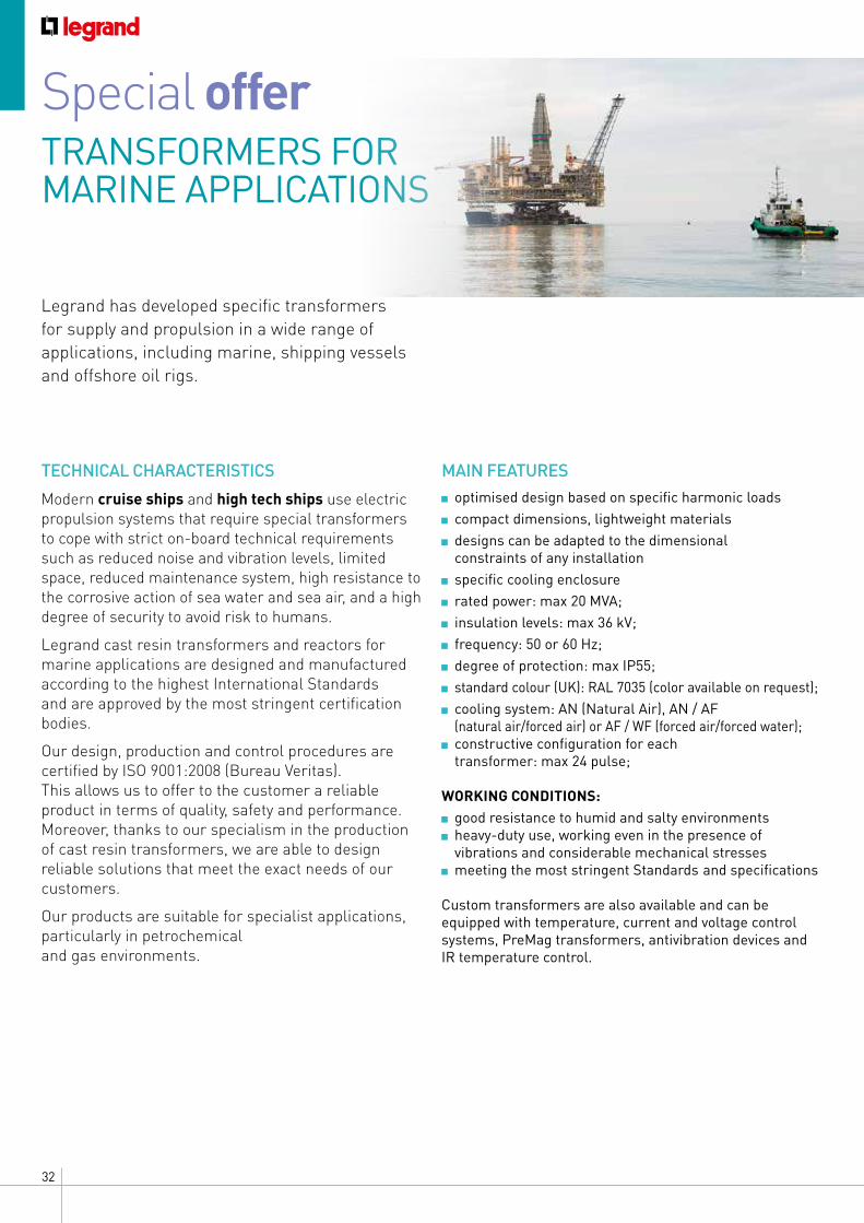
Special offer TRANSFORMERS FOR MARINE APPLICATIONS
Legrand has developed specific transformers for supply and propulsion in a wide range of applications, including marine, shipping vessels and offshore oil rigs.
33CAST RESIN TRANSFORMERS GENERAL FEATURES
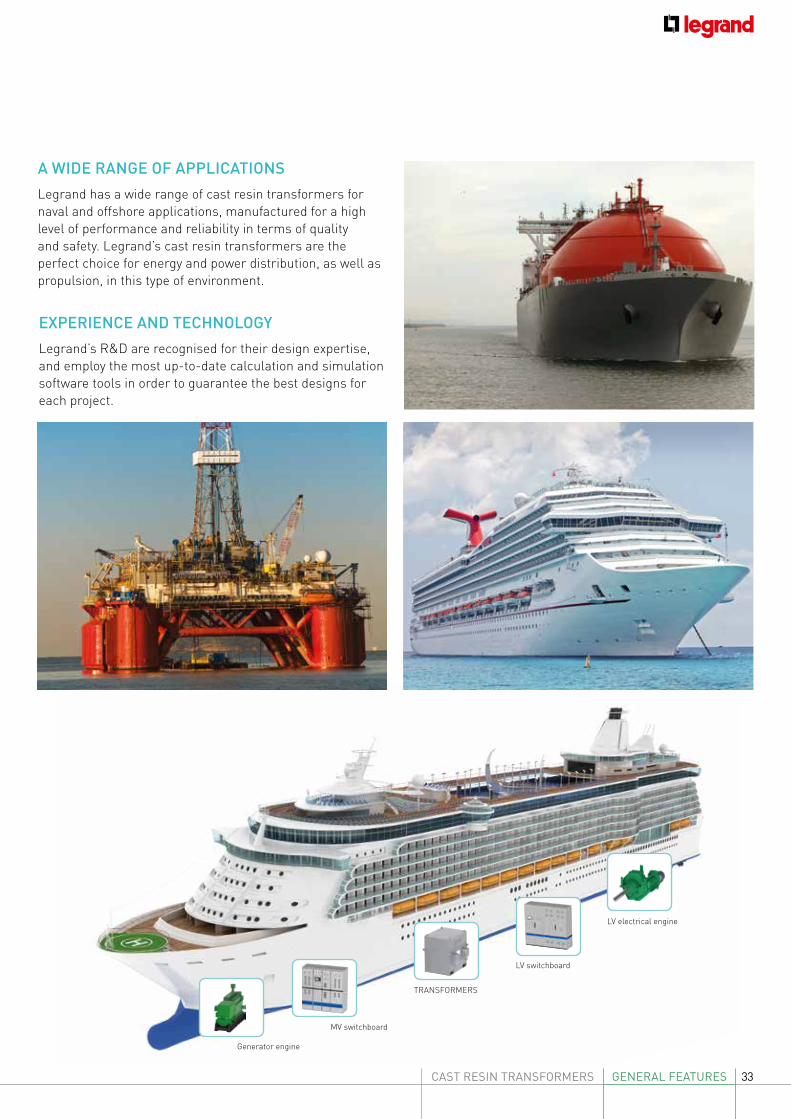
LV electrical engine
LV switchboard
TRANSFORMERS
MV switchboard
Generator engine
A WIDE RANGE OF APPLICATIONSLegrand has a wide range of cast resin transformers for naval and offshore applications, manufactured for a high level of performance and reliability in terms of quality and safety. Legrand’s cast resin transformers are the perfect choice for energy and power distribution, as well as propulsion, in this type of environment.
EXPERIENCE AND TECHNOLOGYLegrand’s R&D are recognised for their design expertise, and employ the most up-to-date calculation and simulation software tools in order to guarantee the best designs for each project.
34 GENERAL FEATURES
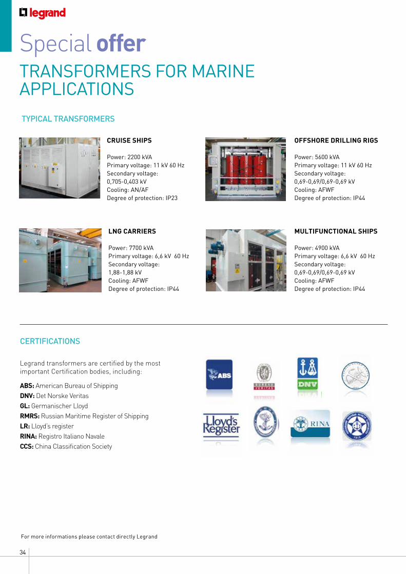
CRUISE SHIPS
Power: 2200 kVAPrimary voltage: 11 kV 60 HzSecondary voltage: 0,705-0,403 kVCooling: AN/AFDegree of protection: IP23
LNG CARRIERS
Power: 7700 kVAPrimary voltage: 6,6 kV 60 HzSecondary voltage: 1,88-1,88 kV Cooling: AFWFDegree of protection: IP44
TYPICAL TRANSFORMERS
MULTIFUNCTIONAL SHIPS
Power: 4900 kVAPrimary voltage: 6,6 kV 60 HzSecondary voltage: 0,69-0,69/0,69-0,69 kVCooling: AFWFDegree of protection: IP44
OFFSHORE DRILLING RIGS
Power: 5600 kVAPrimary voltage: 11 kV 60 HzSecondary voltage: 0,69-0,69/0,69-0,69 kVCooling: AFWFDegree of protection: IP44
Legrand transformers are certified by the most important Certification bodies, including:
ABS: American Bureau of ShippingDNV: Det Norske VeritasGL: Germanischer Lloyd RMRS: Russian Maritime Register of ShippingLR: Lloyd’s registerRINA: Registro Italiano NavaleCCS: China Classification Society
CERTIFICATIONS
For more informations please contact directly Legrand
Special offer TRANSFORMERS FOR MARINE APPLICATIONS
35CAST RESIN TRANSFORMERS GENERAL FEATURES
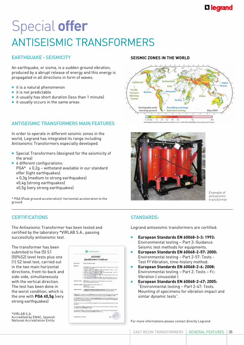
EARTHQUAKE - SEISMICITY
An earthquake, or sisma, is a sudden ground vibration, produced by a abrupt release of energy and this energy is propagated in all directions in form of waves. • it is a natural phenomenon • it is not predictable • it usually has short duration (less than 1 minute) • it usually occurs in the same areas
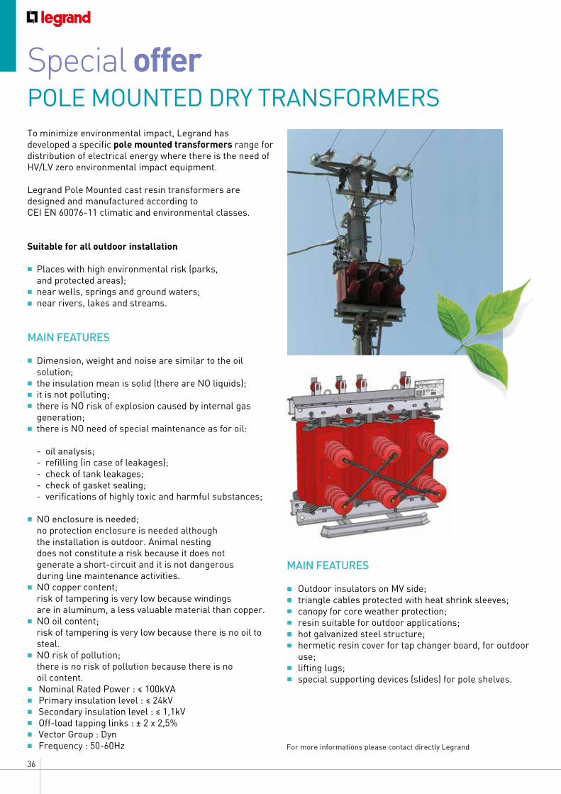
ANTISEISMIC TRANSFORMERS MAIN FEATURES
In order to operate in different seismic zones in the world, Legrand has integrated its range including Antiseismic Transformers especially developed.
• Special Transformers (designed for the seismicity of the area)
• 4 different configurations: PGA* ≤ 0,2g – withstand available in our standard
offer (light earthquakes) ≤ 0,3g (medium to strong earthquakes) ≤0,4g (strong earthquakes) ≤0,5g (very strong earthquakes)
* PGA (Peak ground acceleration): horizontal acceleration to the ground
Example of antiseismic transformer
Special offer ANTISEISMIC TRANSFORMERS
STANDARDS:
Legrand antiseismic transformers are certified:
• European Standards EN 60068-3-3: 1993: Environmental testing – Part 3: Guidance. Seismic test methods for equipments.
• European Standards EN 60068-2-57: 2000: Environmental testing – Part 2-57: Tests - Test Ff Vibration, time-history method.
• European Standards EN 60068-2-6: 2008: Environmental testing – Part 2: Tests – Fc: Vibration ( sinusoidal )
• European Standards EN 60068-2-47: 2005: “Environmental testing – Part 2-47: Tests. Mounting of specimens for vibration impact and simlar dynamic tests”.
For more informations please contact directly Legrand
SEISMIC ZONES IN THE WORLD
CERTIFICATIONS
The Antiseismic Transformer has been tested and certified by the laboratory *VIRLAB S.A., passing successfully antiseismic test.
The transformer has been submited to five (5) S1 (50%S2) level tests plus one (1) S2 level test, carried out in the two main horizontal directions, front-to-back and side-side, simultaneously with the vertical direction. The test has been done in the worst condition, which is the one with PGA ≤0,5g (very strong earthquakes)
*VIRLAB S.A. Accredited by ENAC, Spanish National Accreditation Entity
36 GENERAL FEATURES
Special offer POLE MOUNTED DRY TRANSFORMERS
MAIN FEATURES
• Outdoor insulators on MV side;• triangle cables protected with heat shrink sleeves;• canopy for core weather protection;• resin suitable for outdoor applications;• hot galvanized steel structure;• hermetic resin cover for tap changer board, for outdoor
use;• lifting lugs;• special supporting devices (slides) for pole shelves.
For more informations please contact directly Legrand
To minimize environmental impact, Legrand has developed a specific pole mounted transformers range for distribution of electrical energy where there is the need of HV/LV zero environmental impact equipment.
Legrand Pole Mounted cast resin transformers are designed and manufactured according to CEI EN 60076-11 climatic and environmental classes.
Suitable for all outdoor installation
• Places with high environmental risk (parks, and protected areas);
• near wells, springs and ground waters; • near rivers, lakes and streams.
MAIN FEATURES
• Dimension, weight and noise are similar to the oil solution;
• the insulation mean is solid (there are NO liquids); • it is not polluting; • there is NO risk of explosion caused by internal gas
generation;• there is NO need of special maintenance as for oil: - oil analysis; - refilling (in case of leakages); - check of tank leakages; - check of gasket sealing; - verifications of highly toxic and harmful substances;
• NO enclosure is needed; no protection enclosure is needed although
the installation is outdoor. Animal nesting does not constitute a risk because it does not generate a short-circuit and it is not dangerous during line maintenance activities.
• NO copper content; risk of tampering is very low because windings
are in aluminum, a less valuable material than copper.• NO oil content; risk of tampering is very low because there is no oil to
steal.• NO risk of pollution; there is no risk of pollution because there is no
oil content.• Nominal Rated Power : ≤ 100kVA• Primary insulation level : ≤ 24kV• Secondary insulation level : ≤ 1,1kV• Off-load tapping links : ± 2 x 2,5%• Vector Group : Dyn • Frequency : 50-60Hz
37CAST RESIN TRANSFORMERS GENERAL FEATURES
REACTORS
Special offer
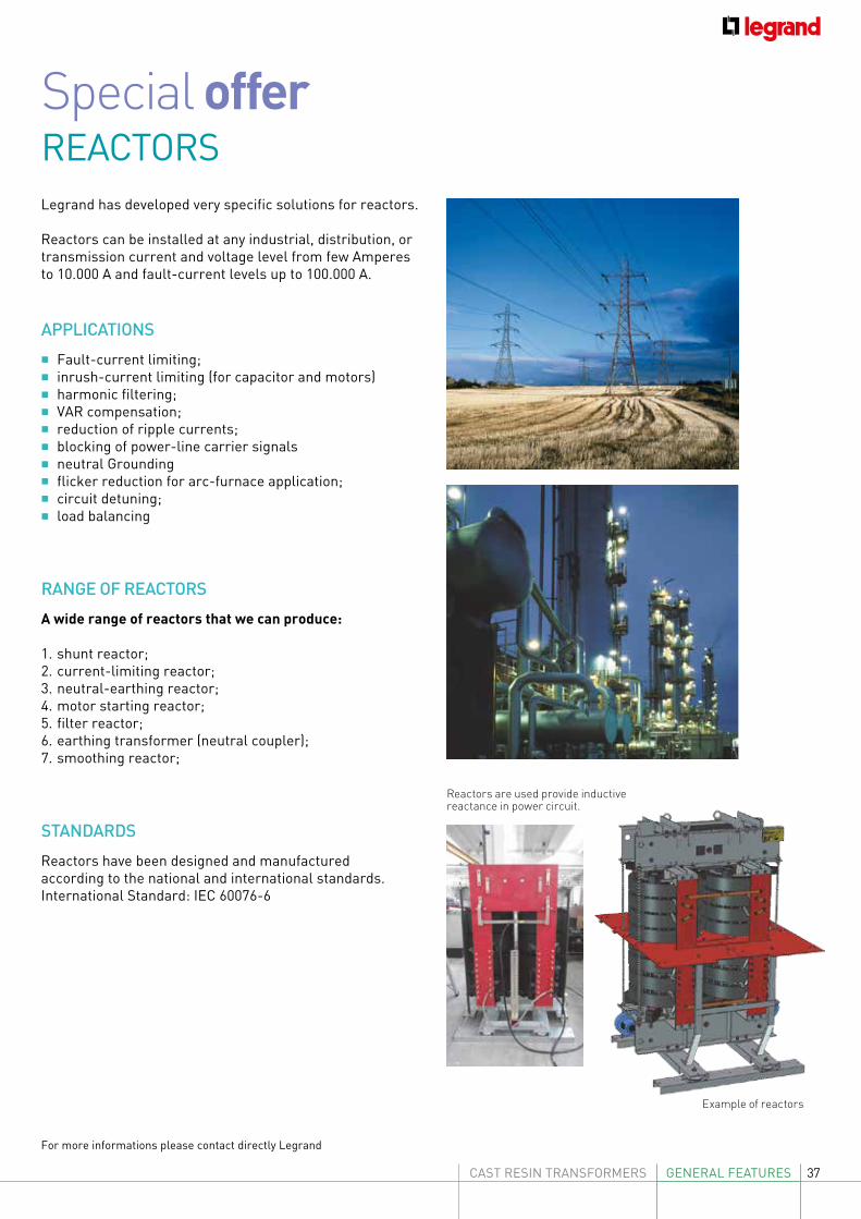
Reactors are used provide inductive reactance in power circuit.
Example of reactors
Legrand has developed very specific solutions for reactors.
Reactors can be installed at any industrial, distribution, or transmission current and voltage level from few Amperes to 10.000 A and fault-current levels up to 100.000 A.
APPLICATIONS
• Fault-current limiting;• inrush-current limiting (for capacitor and motors)• harmonic filtering;• VAR compensation;• reduction of ripple currents;• blocking of power-line carrier signals• neutral Grounding• flicker reduction for arc-furnace application;• circuit detuning;• load balancing
RANGE OF REACTORS
A wide range of reactors that we can produce:
1. shunt reactor;2. current-limiting reactor;3. neutral-earthing reactor; 4. motor starting reactor;5. filter reactor;6. earthing transformer (neutral coupler);7. smoothing reactor;
STANDARDS
Reactors have been designed and manufactured according to the national and international standards. International Standard: IEC 60076-6
For more informations please contact directly Legrand
38 GENERAL FEATURES
CLE SYSTEM (certified low electromagnetic emission)
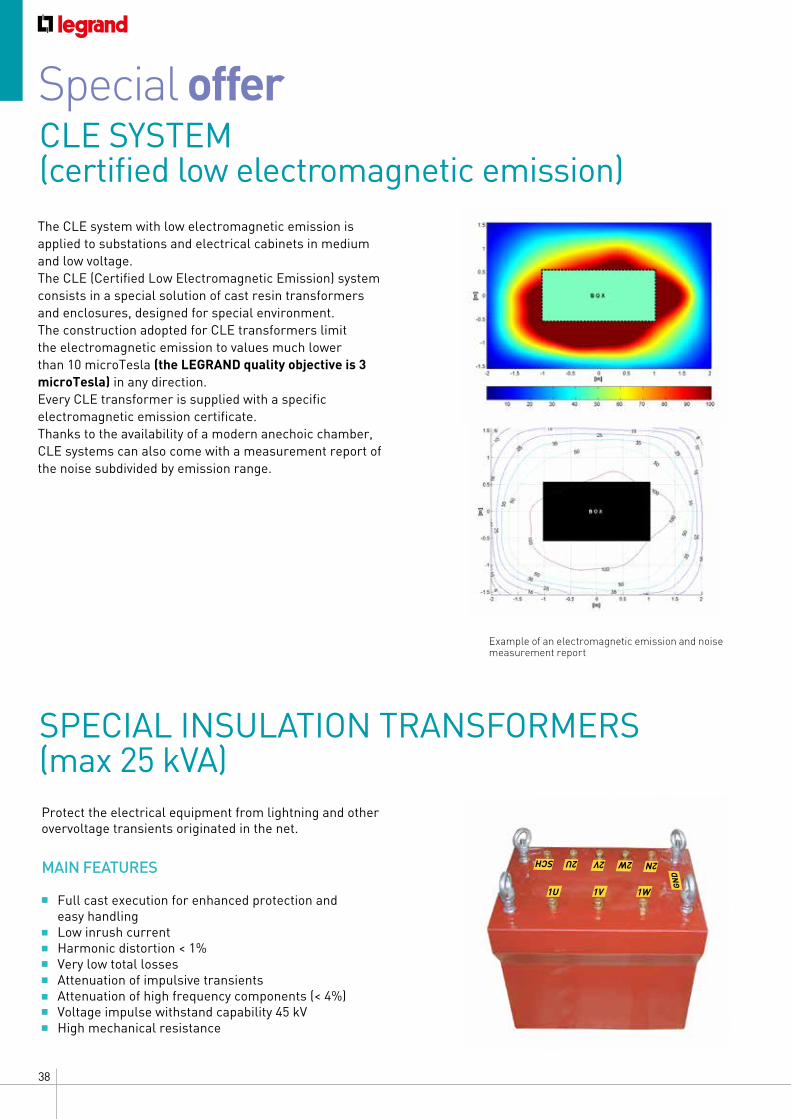
The CLE system with low electromagnetic emission is applied to substations and electrical cabinets in medium and low voltage.The CLE (Certified Low Electromagnetic Emission) system consists in a special solution of cast resin transformers and enclosures, designed for special environment.The construction adopted for CLE transformers limit the electromagnetic emission to values much lower than 10 microTesla (the LEGRAND quality objective is 3 microTesla) in any direction.Every CLE transformer is supplied with a specific electromagnetic emission certificate.Thanks to the availability of a modern anechoic chamber, CLE systems can also come with a measurement report of the noise subdivided by emission range.
Example of an electromagnetic emission and noise measurement report
Special offer
SPECIAL INSULATION TRANSFORMERS (max 25 kVA)Protect the electrical equipment from lightning and other overvoltage transients originated in the net.
MAIN FEATURES
• Full cast execution for enhanced protection and easy handling
• Low inrush current • Harmonic distortion < 1%• Very low total losses • Attenuation of impulsive transients • Attenuation of high frequency components (< 4%)• Voltage impulse withstand capability 45 kV • High mechanical resistance
1U 1V 1W
GN
D
2U 2V 2W 2NSCH
39CAST RESIN TRANSFORMERS GENERAL FEATURES
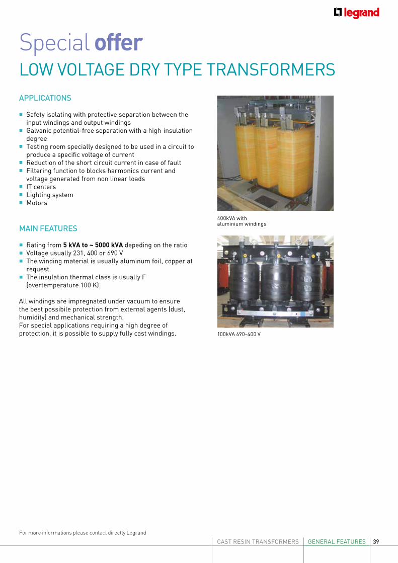
LOW VOLTAGE DRY TYPE TRANSFORMERS
400kVA with aluminium windings
100kVA 690-400 V
For more informations please contact directly Legrand
Special offer
APPLICATIONS
• Safety isolating with protective separation between the input windings and output windings
• Galvanic potential-free separation with a high insulation degree
• Testing room specially designed to be used in a circuit to produce a specific voltage of current
• Reduction of the short circuit current in case of fault• Filtering function to blocks harmonics current and
voltage generated from non linear loads• IT centers• Lighting system• Motors
MAIN FEATURES
Rating from 5 kVA to ~ 5000 kVA depeding on the ratio Voltage usually 231, 400 or 690 V The winding material is usually aluminum foil, copper at
request. The insulation thermal class is usually F
(overtemperature 100 K).
All windings are impregnated under vacuum to ensure the best possibile protection from external agents (dust, humidity) and mechanical strength.For special applications requiring a high degree of protection, it is possible to supply fully cast windings.
40
Special offer
For more informations please contact directly Legrand
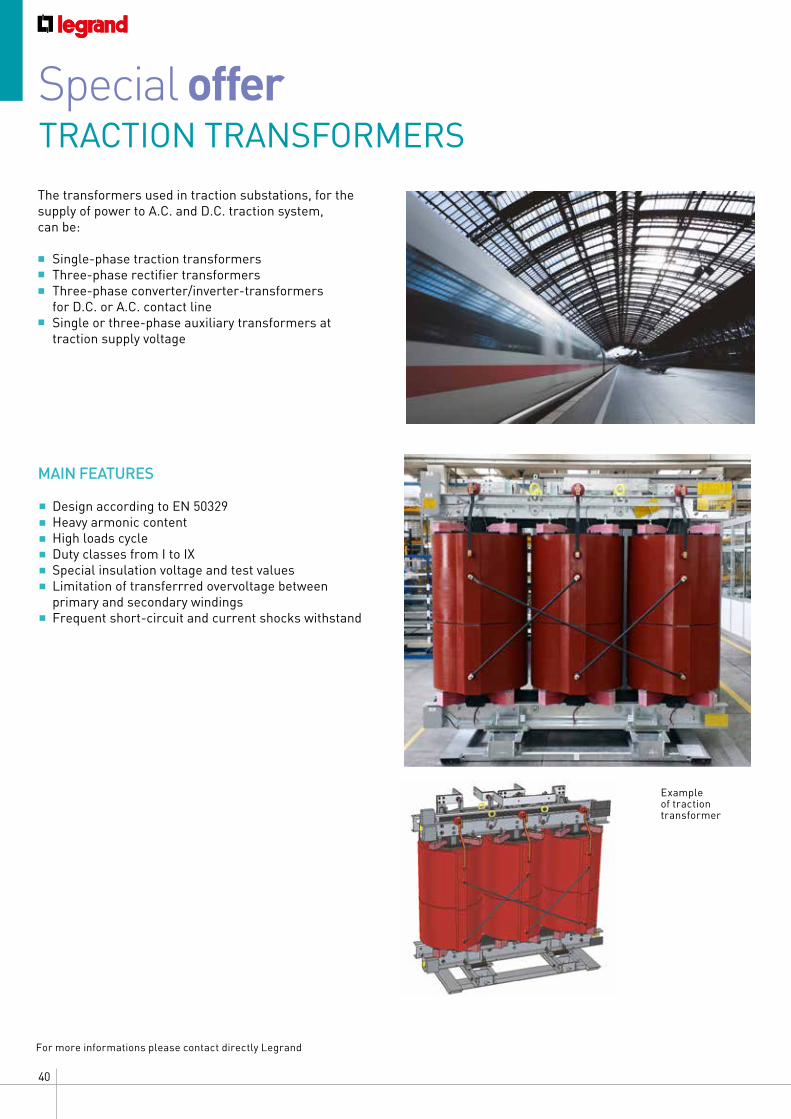
TRACTION TRANSFORMERSThe transformers used in traction substations, for the supply of power to A.C. and D.C. traction system, can be:
• Single-phase traction transformers• Three-phase rectifier transformers• Three-phase converter/inverter-transformers
for D.C. or A.C. contact line• Single or three-phase auxiliary transformers at
traction supply voltage
MAIN FEATURES
Design according to EN 50329 Heavy armonic content High loads cycle Duty classes from I to IX Special insulation voltage and test values Limitation of transferrred overvoltage between
primary and secondary windings Frequent short-circuit and current shocks withstand
Example of traction transformer
41CAST RESIN TRANSFORMERS CATALOGUE
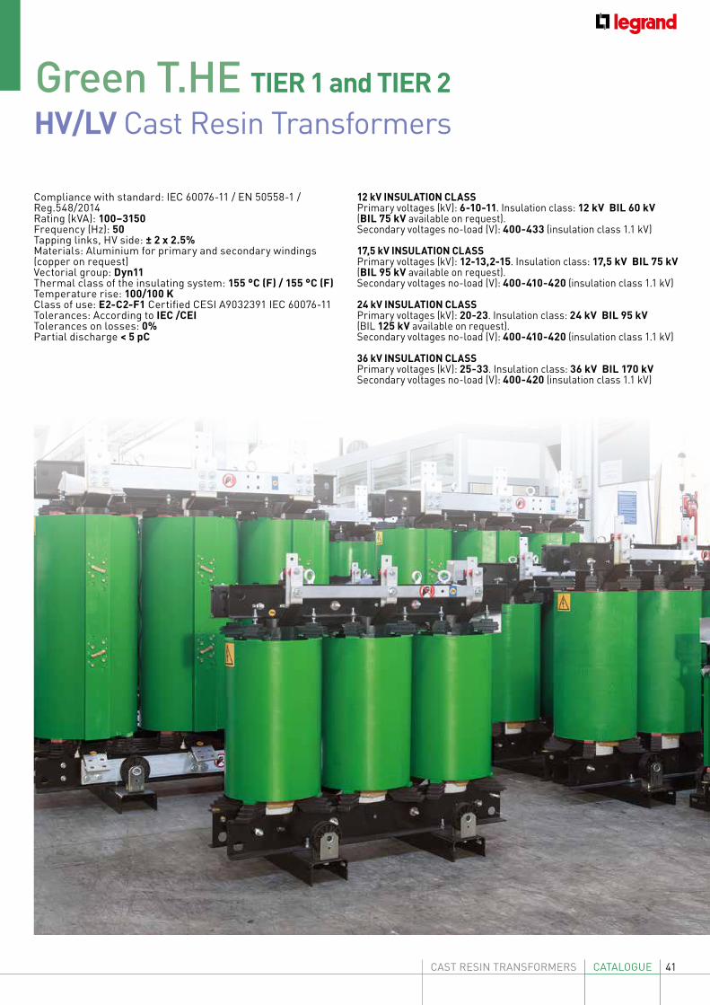
HV/LV Cast Resin TransformersGreen T.HE TIER 1 and TIER 2
Compliance with standard: IEC 60076-11 / EN 50558-1 / Reg.548/2014Rating (kVA): 100–3150Frequency (Hz): 50Tapping links, HV side: ± 2 x 2.5%Materials: Aluminium for primary and secondary windings (copper on request)Vectorial group: Dyn11Thermal class of the insulating system: 155 °C (F) / 155 °C (F)Temperature rise: 100/100 KClass of use: E2-C2-F1 Certified CESI A9032391 IEC 60076-11Tolerances: According to IEC /CEI Tolerances on losses: 0%Partial discharge < 5 pC
12 kV INSULATION CLASSPrimary voltages (kV): 6-10-11. Insulation class: 12 kV BIL 60 kV (BIL 75 kV available on request). Secondary voltages no-load (V): 400-433 (insulation class 1.1 kV)
17,5 kV INSULATION CLASSPrimary voltages (kV): 12-13,2-15. Insulation class: 17,5 kV BIL 75 kV (BIL 95 kV available on request). Secondary voltages no-load (V): 400-410-420 (insulation class 1.1 kV)
24 kV INSULATION CLASSPrimary voltages (kV): 20-23. Insulation class: 24 kV BIL 95 kV(BIL 125 kV available on request).Secondary voltages no-load (V): 400-410-420 (insulation class 1.1 kV)
36 kV INSULATION CLASSPrimary voltages (kV): 25-33. Insulation class: 36 kV BIL 170 kVSecondary voltages no-load (V): 400-420 (insulation class 1.1 kV)
42
A
ØR
=Ic Ic=
C
=
5040 (Ø125)
70 (Ø200) (Ø160)
=
B
60
M12
M12
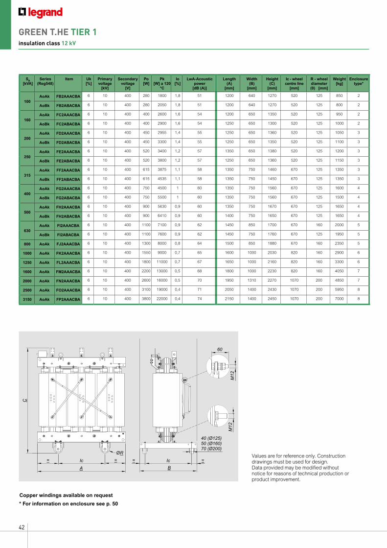
Values are for reference only. Construction drawings must be used for design. Data provided may be modified without notice for reasons of technical production or product improvement.
* For information on enclosure see p. 50
SR [kVA]
Series(Reg548)
Item Uk [%]
Primary voltage
[kV]
Secondary voltage
[V]
Po [W]
Pk [W] a 120
°C
Io [%]
LwA-Acoustic power
[dB (A)]
Length(A)
[mm]
Width(B)
[mm]
Height (C)
[mm]
Ic - wheel centre line
[mm]
R - wheel diameter (0) [mm]
Weight [kg]
Enclosuretype*
100AoAk FB2AAACBA 6 10 400 280 1800 1,8 51 1200 640 1270 520 125 850 2
AoBk FB2ABACBA 6 10 400 280 2050 1,8 51 1200 640 1270 520 125 800 2
160AoAk FC2AAACBA 6 10 400 400 2600 1,6 54 1200 650 1350 520 125 950 2
AoBk FC2ABACBA 6 10 400 400 2900 1,6 54 1250 650 1300 520 125 1000 2
200AoAk FD2AAACBA 6 10 400 450 2955 1,4 55 1250 650 1360 520 125 1050 3
AoBk FD2ABACBA 6 10 400 450 3300 1,4 55 1250 650 1350 520 125 1100 3
250AoAk FE2AAACBA 6 10 400 520 3400 1,2 57 1350 650 1380 520 125 1200 3
AoBk FE2ABACBA 6 10 400 520 3800 1,2 57 1250 650 1360 520 125 1150 3
315AoAk FF2AAACBA 6 10 400 615 3875 1,1 58 1350 750 1460 670 125 1350 3
AoBk FF2ABACBA 6 10 400 615 4535 1,1 58 1350 750 1450 670 125 1350 3
400AoAk FG2AAACBA 6 10 400 750 4500 1 60 1350 750 1560 670 125 1600 4
AoBk FG2ABACBA 6 10 400 750 5500 1 60 1350 750 1560 670 125 1500 4
500AoAk FH2AAACBA 6 10 400 900 5630 0,9 60 1350 750 1670 670 125 1650 4
AoBk FH2ABACBA 6 10 400 900 6410 0,9 60 1400 750 1650 670 125 1650 4
630AoAk FI2AAACBA 6 10 400 1100 7100 0,9 62 1450 850 1700 670 160 2000 5
AoBk FI2ABACBA 6 10 400 1100 7600 0,9 62 1450 750 1760 670 125 1950 5
800 AoAk FJ2AAACBA 6 10 400 1300 8000 0,8 64 1500 850 1880 670 160 2350 5
1000 AoAk FK2AAACBA 6 10 400 1550 9000 0,7 65 1600 1000 2030 820 160 2900 6
1250 AoAk FL2AAACBA 6 10 400 1800 11000 0,7 67 1650 1000 2160 820 160 3300 6
1600 AoAk FM2AAACBA 6 10 400 2200 13000 0,5 68 1800 1000 2230 820 160 4050 7
2000 AoAk FN2AAACBA 6 10 400 2600 16000 0,5 70 1950 1310 2270 1070 200 4850 7
2500 AoAk FO2AAACBA 6 10 400 3100 19000 0,4 71 2050 1400 2430 1070 200 5950 8
3150 AoAk FP2AAACBA 6 10 400 3800 22000 0,4 74 2150 1400 2450 1070 200 7000 8
Copper windings available on request
GREEN T.HE TIER 1insulation class 12 kV
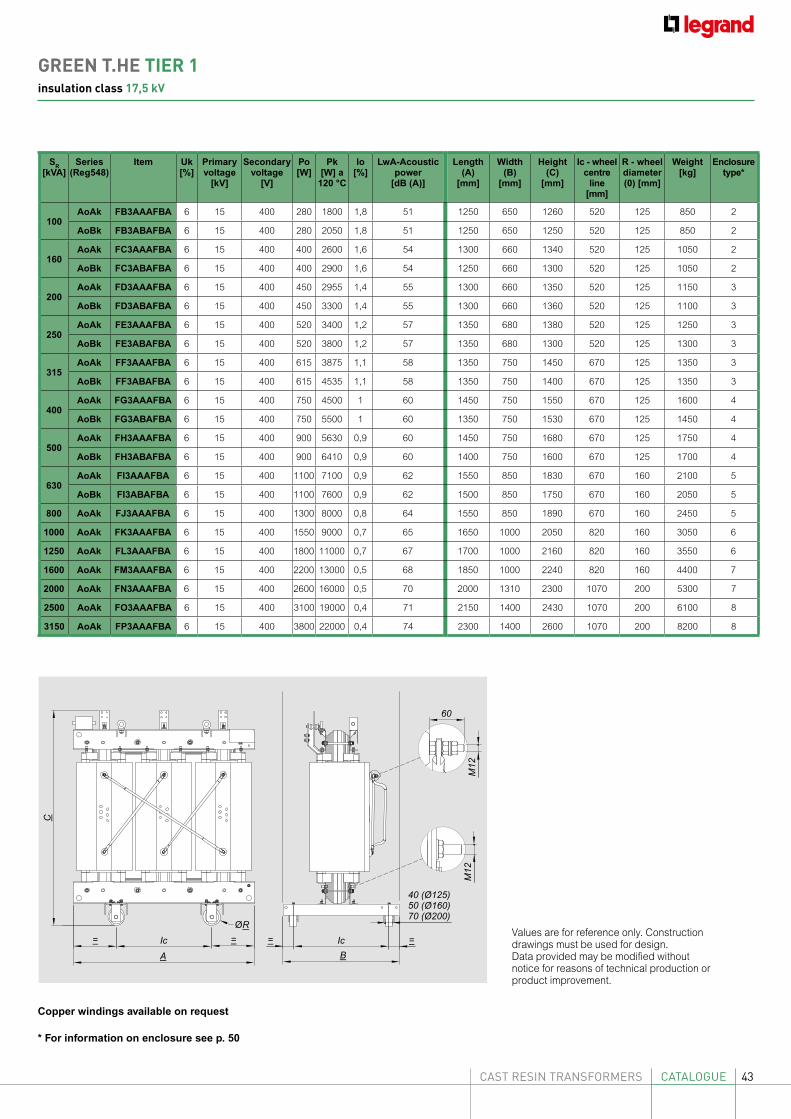
43CAST RESIN TRANSFORMERS CATALOGUE
SR [kVA]
Series(Reg548)
Item Uk [%]
Primary voltage
[kV]
Secondary voltage
[V]
Po [W]
Pk [W] a
120 °C
Io [%]
LwA-Acoustic power
[dB (A)]
Length(A)
[mm]
Width(B)
[mm]
Height (C)
[mm]
Ic - wheel centre
line [mm]
R - wheel diameter (0) [mm]
Weight [kg]
Enclosuretype*
100AoAk FB3AAAFBA 6 15 400 280 1800 1,8 51 1250 650 1260 520 125 850 2
AoBk FB3ABAFBA 6 15 400 280 2050 1,8 51 1250 650 1250 520 125 850 2
160AoAk FC3AAAFBA 6 15 400 400 2600 1,6 54 1300 660 1340 520 125 1050 2
AoBk FC3ABAFBA 6 15 400 400 2900 1,6 54 1250 660 1300 520 125 1050 2
200AoAk FD3AAAFBA 6 15 400 450 2955 1,4 55 1300 660 1350 520 125 1150 3
AoBk FD3ABAFBA 6 15 400 450 3300 1,4 55 1300 660 1360 520 125 1100 3
250AoAk FE3AAAFBA 6 15 400 520 3400 1,2 57 1350 680 1380 520 125 1250 3
AoBk FE3ABAFBA 6 15 400 520 3800 1,2 57 1350 680 1300 520 125 1300 3
315AoAk FF3AAAFBA 6 15 400 615 3875 1,1 58 1350 750 1450 670 125 1350 3
AoBk FF3ABAFBA 6 15 400 615 4535 1,1 58 1350 750 1400 670 125 1350 3
400AoAk FG3AAAFBA 6 15 400 750 4500 1 60 1450 750 1550 670 125 1600 4
AoBk FG3ABAFBA 6 15 400 750 5500 1 60 1350 750 1530 670 125 1450 4
500AoAk FH3AAAFBA 6 15 400 900 5630 0,9 60 1450 750 1680 670 125 1750 4
AoBk FH3ABAFBA 6 15 400 900 6410 0,9 60 1400 750 1600 670 125 1700 4
630AoAk FI3AAAFBA 6 15 400 1100 7100 0,9 62 1550 850 1830 670 160 2100 5
AoBk FI3ABAFBA 6 15 400 1100 7600 0,9 62 1500 850 1750 670 160 2050 5
800 AoAk FJ3AAAFBA 6 15 400 1300 8000 0,8 64 1550 850 1890 670 160 2450 5
1000 AoAk FK3AAAFBA 6 15 400 1550 9000 0,7 65 1650 1000 2050 820 160 3050 6
1250 AoAk FL3AAAFBA 6 15 400 1800 11000 0,7 67 1700 1000 2160 820 160 3550 6
1600 AoAk FM3AAAFBA 6 15 400 2200 13000 0,5 68 1850 1000 2240 820 160 4400 7
2000 AoAk FN3AAAFBA 6 15 400 2600 16000 0,5 70 2000 1310 2300 1070 200 5300 7
2500 AoAk FO3AAAFBA 6 15 400 3100 19000 0,4 71 2150 1400 2430 1070 200 6100 8
3150 AoAk FP3AAAFBA 6 15 400 3800 22000 0,4 74 2300 1400 2600 1070 200 8200 8
Copper windings available on request
A
ØR
=Ic Ic=
C
=
5040 (Ø125)
70 (Ø200) (Ø160)
=
B
60
M12
M12
Values are for reference only. Construction drawings must be used for design. Data provided may be modified without notice for reasons of technical production or product improvement.
* For information on enclosure see p. 50
GREEN T.HE TIER 1insulation class 17,5 kV
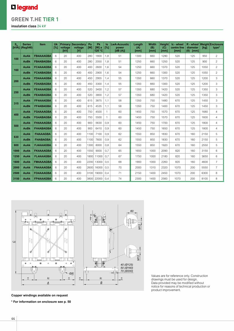
44
SR [kVA]
Series(Reg548)
Item Uk [%]
Primary voltage
[kV]
Secondary voltage
[V]
Po [W]
Pk [W] a
120 °C
Io [%]
LwA-Acoustic power
[dB (A)]
Length(A)
[mm]
Width(B)
[mm]
Height (C)
[mm]
Ic - wheel centre line
[mm]
R - wheel diameter (0) [mm]
Weight [kg]
Enclosuretype*
100AoAk FB4AAAGBA 6 20 400 280 1800 1,8 51 1300 660 1290 520 125 950 2
AoBk FB4ABAGBA 6 20 400 280 2050 1,8 51 1250 660 1250 520 125 900 2
160AoAk FC4AAAGBA 6 20 400 400 2600 1,6 54 1250 660 1370 520 125 1050 2
AoBk FC4ABAGBA 6 20 400 400 2900 1,6 54 1250 660 1300 520 125 1050 2
200AoAk FD4AAAGBA 6 20 400 450 2955 1,4 55 1350 660 1370 520 125 1200 3
AoBk FD4ABAGBA 6 20 400 450 3300 1,4 55 1350 660 1300 520 125 1200 3
250AoAk FE4AAAGBA 6 20 400 520 3400 1,2 57 1350 680 1420 520 125 1350 3
AoBk FE4ABAGBA 6 20 400 520 3800 1,2 57 1350 680 1420 520 125 1350 3
315AoAk FF4AAAGBA 6 20 400 615 3875 1,1 58 1350 750 1480 670 125 1450 3
AoBk FF4ABAGBA 6 20 400 615 4535 1,1 58 1350 750 1400 670 125 1450 3
400AoAk FG4AAAGBA 6 20 400 750 4500 1 60 1450 750 1570 670 125 1680 4
AoBk FG4ABAGBA 6 20 400 750 5500 1 60 1450 750 1570 670 125 1600 4
500AoAk FH4AAAGBA 6 20 400 900 5630 0,9 60 1450 750 1700 670 125 1800 4
AoBk FH4ABAGBA 6 20 400 900 6410 0,9 60 1450 750 1650 670 125 1800 4
630AoAk FI4AAAGBA 6 20 400 1100 7100 0,9 62 1550 850 1830 670 160 2150 5
AoBk FI4ABAGBA 6 20 400 1100 7600 0,9 62 1550 850 1830 670 160 2150 5
800 AoAk FJ4AAAGBA 6 20 400 1300 8000 0,8 64 1550 850 1920 670 160 2550 5
1000 AoAk FK4AAAGBA 6 20 400 1550 9000 0,7 65 1650 1000 2090 820 160 3150 6
1250 AoAk FL4AAAGBA 6 20 400 1800 11000 0,7 67 1750 1000 2180 820 160 3650 6
1600 AoAk FM4AAAGBA 6 20 400 2200 13000 0,5 68 1900 1000 2260 820 160 4600 7
2000 AoAk FN4AAAGBA 6 20 400 2600 16000 0,5 70 2000 1310 2320 1070 200 5550 7
2500 AoAk FO4AAAGBA 6 20 400 3100 19000 0,4 71 2150 1400 2450 1070 200 6300 8
3150 AoAk FP4AAAGBA 6 20 400 3800 22000 0,4 74 2300 1400 2560 1070 200 8100 8
Copper windings available on request
A
ØR
=Ic Ic=
C
=
5040 (Ø125)
70 (Ø200) (Ø160)
=
B
60
M12
M12
Values are for reference only. Construction drawings must be used for design. Data provided may be modified without notice for reasons of technical production or product improvement.
* For information on enclosure see p. 50
GREEN T.HE TIER 1insulation class 24 kV
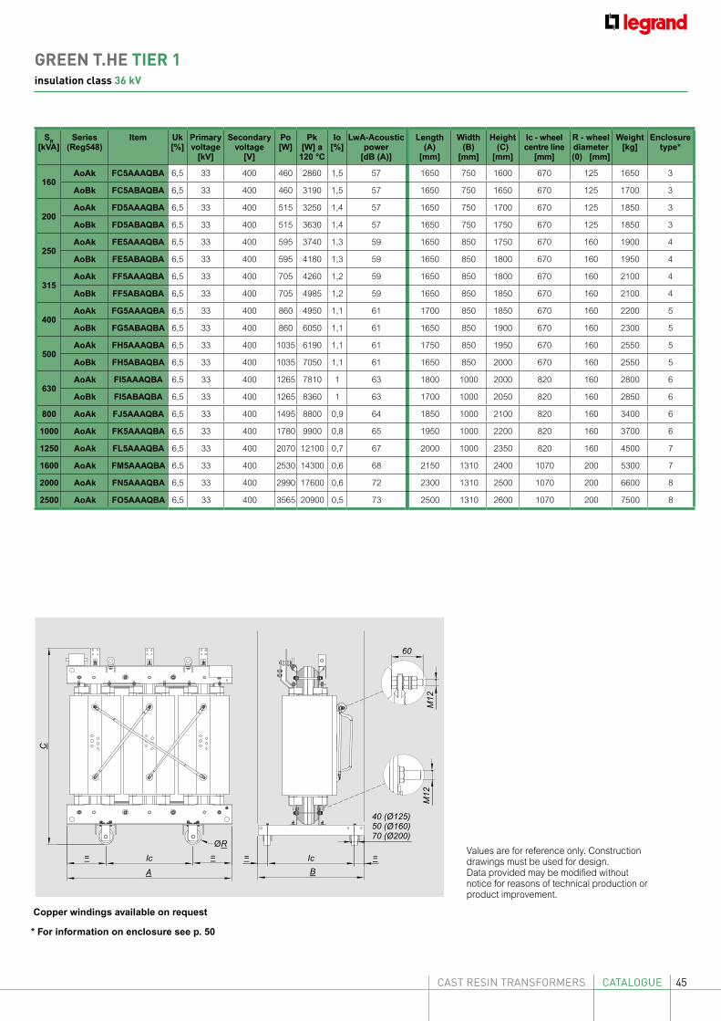
45CAST RESIN TRANSFORMERS CATALOGUE
SR [kVA]
Series(Reg548)
Item Uk [%]
Primary voltage
[kV]
Secondary voltage
[V]
Po [W]
Pk [W] a
120 °C
Io [%]
LwA-Acoustic power
[dB (A)]
Length(A)
[mm]
Width(B)
[mm]
Height (C)
[mm]
Ic - wheel centre line
[mm]
R - wheel diameter (0) [mm]
Weight [kg]
Enclosuretype*
160AoAk FC5AAAQBA 6,5 33 400 460 2860 1,5 57 1650 750 1600 670 125 1650 3
AoBk FC5ABAQBA 6,5 33 400 460 3190 1,5 57 1650 750 1650 670 125 1700 3
200AoAk FD5AAAQBA 6,5 33 400 515 3250 1,4 57 1650 750 1700 670 125 1850 3
AoBk FD5ABAQBA 6,5 33 400 515 3630 1,4 57 1650 750 1750 670 125 1850 3
250AoAk FE5AAAQBA 6,5 33 400 595 3740 1,3 59 1650 850 1750 670 160 1900 4
AoBk FE5ABAQBA 6,5 33 400 595 4180 1,3 59 1650 850 1800 670 160 1950 4
315AoAk FF5AAAQBA 6,5 33 400 705 4260 1,2 59 1650 850 1800 670 160 2100 4
AoBk FF5ABAQBA 6,5 33 400 705 4985 1,2 59 1650 850 1850 670 160 2100 4
400AoAk FG5AAAQBA 6,5 33 400 860 4950 1,1 61 1700 850 1850 670 160 2200 5
AoBk FG5ABAQBA 6,5 33 400 860 6050 1,1 61 1650 850 1900 670 160 2300 5
500AoAk FH5AAAQBA 6,5 33 400 1035 6190 1,1 61 1750 850 1950 670 160 2550 5
AoBk FH5ABAQBA 6,5 33 400 1035 7050 1,1 61 1650 850 2000 670 160 2550 5
630AoAk FI5AAAQBA 6,5 33 400 1265 7810 1 63 1800 1000 2000 820 160 2800 6
AoBk FI5ABAQBA 6,5 33 400 1265 8360 1 63 1700 1000 2050 820 160 2850 6
800 AoAk FJ5AAAQBA 6,5 33 400 1495 8800 0,9 64 1850 1000 2100 820 160 3400 6
1000 AoAk FK5AAAQBA 6,5 33 400 1780 9900 0,8 65 1950 1000 2200 820 160 3700 6
1250 AoAk FL5AAAQBA 6,5 33 400 2070 12100 0,7 67 2000 1000 2350 820 160 4500 7
1600 AoAk FM5AAAQBA 6,5 33 400 2530 14300 0,6 68 2150 1310 2400 1070 200 5300 7
2000 AoAk FN5AAAQBA 6,5 33 400 2990 17600 0,6 72 2300 1310 2500 1070 200 6600 8
2500 AoAk FO5AAAQBA 6,5 33 400 3565 20900 0,5 73 2500 1310 2600 1070 200 7500 8
A
ØR
=Ic Ic=
C
=
5040 (Ø125)
70 (Ø200) (Ø160)
=
B
60
M12
M12
Values are for reference only. Construction drawings must be used for design. Data provided may be modified without notice for reasons of technical production or product improvement.
Copper windings available on request
* For information on enclosure see p. 50
GREEN T.HE TIER 1insulation class 36 kV
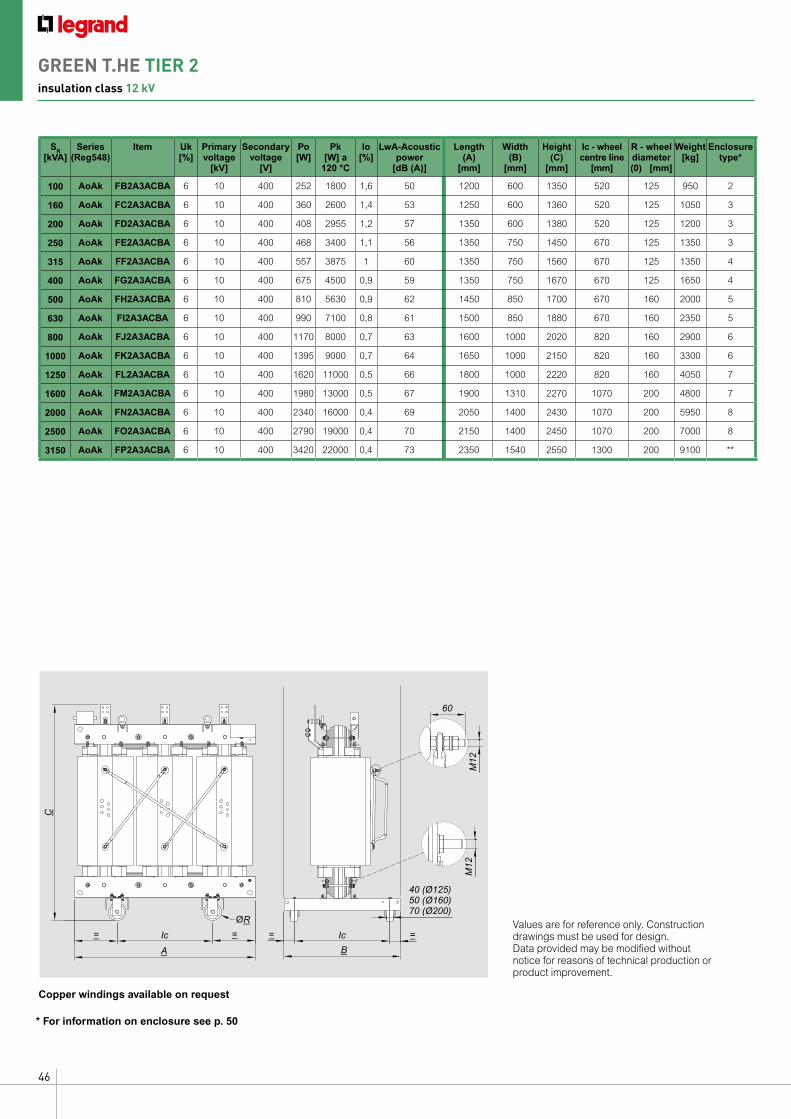
46
A
ØR
=Ic Ic=
C
=
5040 (Ø125)
70 (Ø200) (Ø160)
=
B
60
M12
M12
Values are for reference only. Construction drawings must be used for design. Data provided may be modified without notice for reasons of technical production or product improvement.
SR [kVA]
Series(Reg548)
Item Uk [%]
Primary voltage
[kV]
Secondary voltage
[V]
Po [W]
Pk [W] a
120 °C
Io [%]
LwA-Acoustic power
[dB (A)]
Length(A)
[mm]
Width(B)
[mm]
Height (C)
[mm]
Ic - wheel centre line
[mm]
R - wheel diameter (0) [mm]
Weight [kg]
Enclosuretype*
100 AoAk FB2A3ACBA 6 10 400 252 1800 1,6 50 1200 600 1350 520 125 950 2
160 AoAk FC2A3ACBA 6 10 400 360 2600 1,4 53 1250 600 1360 520 125 1050 3
200 AoAk FD2A3ACBA 6 10 400 408 2955 1,2 57 1350 600 1380 520 125 1200 3
250 AoAk FE2A3ACBA 6 10 400 468 3400 1,1 56 1350 750 1450 670 125 1350 3
315 AoAk FF2A3ACBA 6 10 400 557 3875 1 60 1350 750 1560 670 125 1350 4
400 AoAk FG2A3ACBA 6 10 400 675 4500 0,9 59 1350 750 1670 670 125 1650 4
500 AoAk FH2A3ACBA 6 10 400 810 5630 0,9 62 1450 850 1700 670 160 2000 5
630 AoAk FI2A3ACBA 6 10 400 990 7100 0,8 61 1500 850 1880 670 160 2350 5
800 AoAk FJ2A3ACBA 6 10 400 1170 8000 0,7 63 1600 1000 2020 820 160 2900 6
1000 AoAk FK2A3ACBA 6 10 400 1395 9000 0,7 64 1650 1000 2150 820 160 3300 6
1250 AoAk FL2A3ACBA 6 10 400 1620 11000 0,5 66 1800 1000 2220 820 160 4050 7
1600 AoAk FM2A3ACBA 6 10 400 1980 13000 0,5 67 1900 1310 2270 1070 200 4800 7
2000 AoAk FN2A3ACBA 6 10 400 2340 16000 0,4 69 2050 1400 2430 1070 200 5950 8
2500 AoAk FO2A3ACBA 6 10 400 2790 19000 0,4 70 2150 1400 2450 1070 200 7000 8
3150 AoAk FP2A3ACBA 6 10 400 3420 22000 0,4 73 2350 1540 2550 1300 200 9100 **
Copper windings available on request
* For information on enclosure see p. 50
GREEN T.HE TIER 2insulation class 12 kV
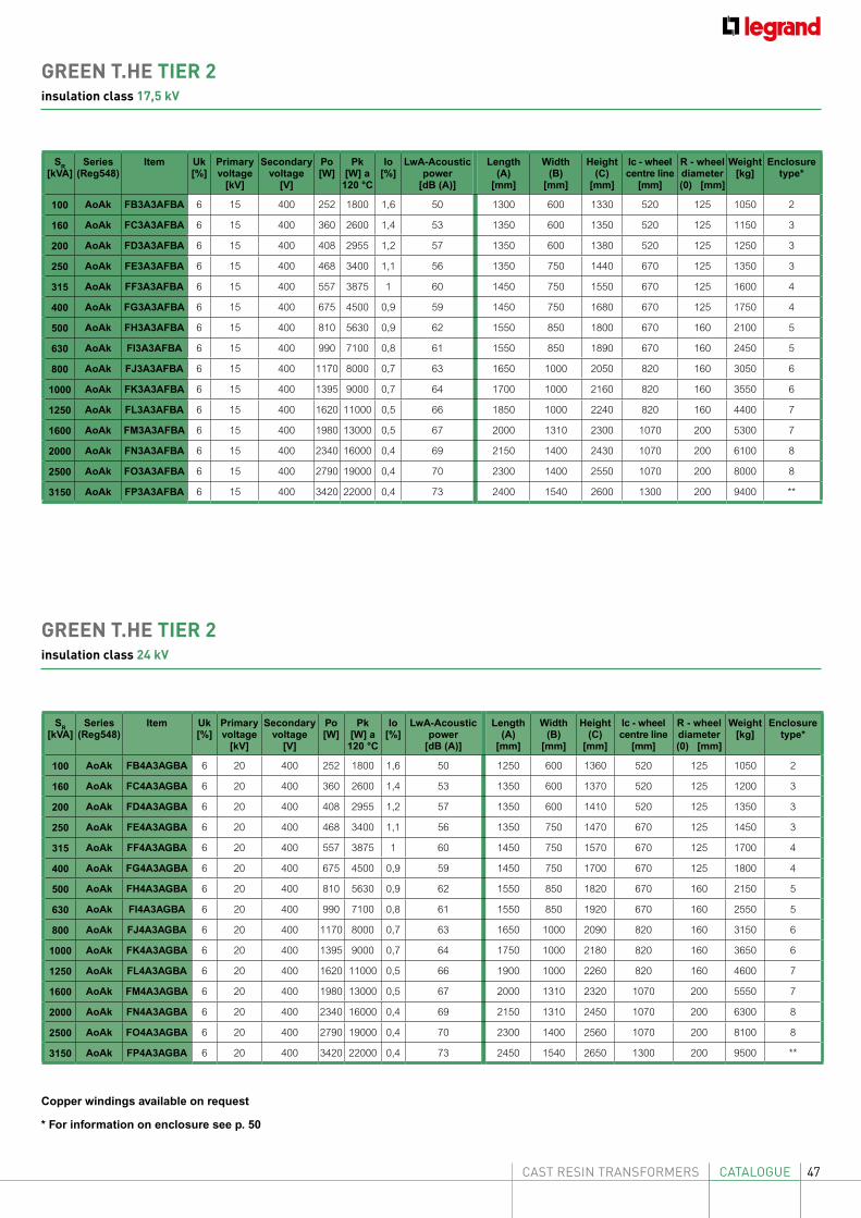
47CAST RESIN TRANSFORMERS CATALOGUE
SR [kVA]
Series(Reg548)
Item Uk [%]
Primary voltage
[kV]
Secondary voltage
[V]
Po [W]
Pk [W] a
120 °C
Io [%]
LwA-Acoustic power
[dB (A)]
Length(A)
[mm]
Width(B)
[mm]
Height (C)
[mm]
Ic - wheel centre line
[mm]
R - wheel diameter (0) [mm]
Weight [kg]
Enclosuretype*
100 AoAk FB3A3AFBA 6 15 400 252 1800 1,6 50 1300 600 1330 520 125 1050 2
160 AoAk FC3A3AFBA 6 15 400 360 2600 1,4 53 1350 600 1350 520 125 1150 3
200 AoAk FD3A3AFBA 6 15 400 408 2955 1,2 57 1350 600 1380 520 125 1250 3
250 AoAk FE3A3AFBA 6 15 400 468 3400 1,1 56 1350 750 1440 670 125 1350 3
315 AoAk FF3A3AFBA 6 15 400 557 3875 1 60 1450 750 1550 670 125 1600 4
400 AoAk FG3A3AFBA 6 15 400 675 4500 0,9 59 1450 750 1680 670 125 1750 4
500 AoAk FH3A3AFBA 6 15 400 810 5630 0,9 62 1550 850 1800 670 160 2100 5
630 AoAk FI3A3AFBA 6 15 400 990 7100 0,8 61 1550 850 1890 670 160 2450 5
800 AoAk FJ3A3AFBA 6 15 400 1170 8000 0,7 63 1650 1000 2050 820 160 3050 6
1000 AoAk FK3A3AFBA 6 15 400 1395 9000 0,7 64 1700 1000 2160 820 160 3550 6
1250 AoAk FL3A3AFBA 6 15 400 1620 11000 0,5 66 1850 1000 2240 820 160 4400 7
1600 AoAk FM3A3AFBA 6 15 400 1980 13000 0,5 67 2000 1310 2300 1070 200 5300 7
2000 AoAk FN3A3AFBA 6 15 400 2340 16000 0,4 69 2150 1400 2430 1070 200 6100 8
2500 AoAk FO3A3AFBA 6 15 400 2790 19000 0,4 70 2300 1400 2550 1070 200 8000 8
3150 AoAk FP3A3AFBA 6 15 400 3420 22000 0,4 73 2400 1540 2600 1300 200 9400 **
SR [kVA]
Series(Reg548)
Item Uk [%]
Primary voltage
[kV]
Secondary voltage
[V]
Po [W]
Pk [W] a
120 °C
Io [%]
LwA-Acoustic power
[dB (A)]
Length(A)
[mm]
Width(B)
[mm]
Height (C)
[mm]
Ic - wheel centre line
[mm]
R - wheel diameter (0) [mm]
Weight [kg]
Enclosuretype*
100 AoAk FB4A3AGBA 6 20 400 252 1800 1,6 50 1250 600 1360 520 125 1050 2
160 AoAk FC4A3AGBA 6 20 400 360 2600 1,4 53 1350 600 1370 520 125 1200 3
200 AoAk FD4A3AGBA 6 20 400 408 2955 1,2 57 1350 600 1410 520 125 1350 3
250 AoAk FE4A3AGBA 6 20 400 468 3400 1,1 56 1350 750 1470 670 125 1450 3
315 AoAk FF4A3AGBA 6 20 400 557 3875 1 60 1450 750 1570 670 125 1700 4
400 AoAk FG4A3AGBA 6 20 400 675 4500 0,9 59 1450 750 1700 670 125 1800 4
500 AoAk FH4A3AGBA 6 20 400 810 5630 0,9 62 1550 850 1820 670 160 2150 5
630 AoAk FI4A3AGBA 6 20 400 990 7100 0,8 61 1550 850 1920 670 160 2550 5
800 AoAk FJ4A3AGBA 6 20 400 1170 8000 0,7 63 1650 1000 2090 820 160 3150 6
1000 AoAk FK4A3AGBA 6 20 400 1395 9000 0,7 64 1750 1000 2180 820 160 3650 6
1250 AoAk FL4A3AGBA 6 20 400 1620 11000 0,5 66 1900 1000 2260 820 160 4600 7
1600 AoAk FM4A3AGBA 6 20 400 1980 13000 0,5 67 2000 1310 2320 1070 200 5550 7
2000 AoAk FN4A3AGBA 6 20 400 2340 16000 0,4 69 2150 1310 2450 1070 200 6300 8
2500 AoAk FO4A3AGBA 6 20 400 2790 19000 0,4 70 2300 1400 2560 1070 200 8100 8
3150 AoAk FP4A3AGBA 6 20 400 3420 22000 0,4 73 2450 1540 2650 1300 200 9500 **
Copper windings available on request
* For information on enclosure see p. 50
GREEN T.HE TIER 2insulation class 17,5 kV
GREEN T.HE TIER 2insulation class 24 kV
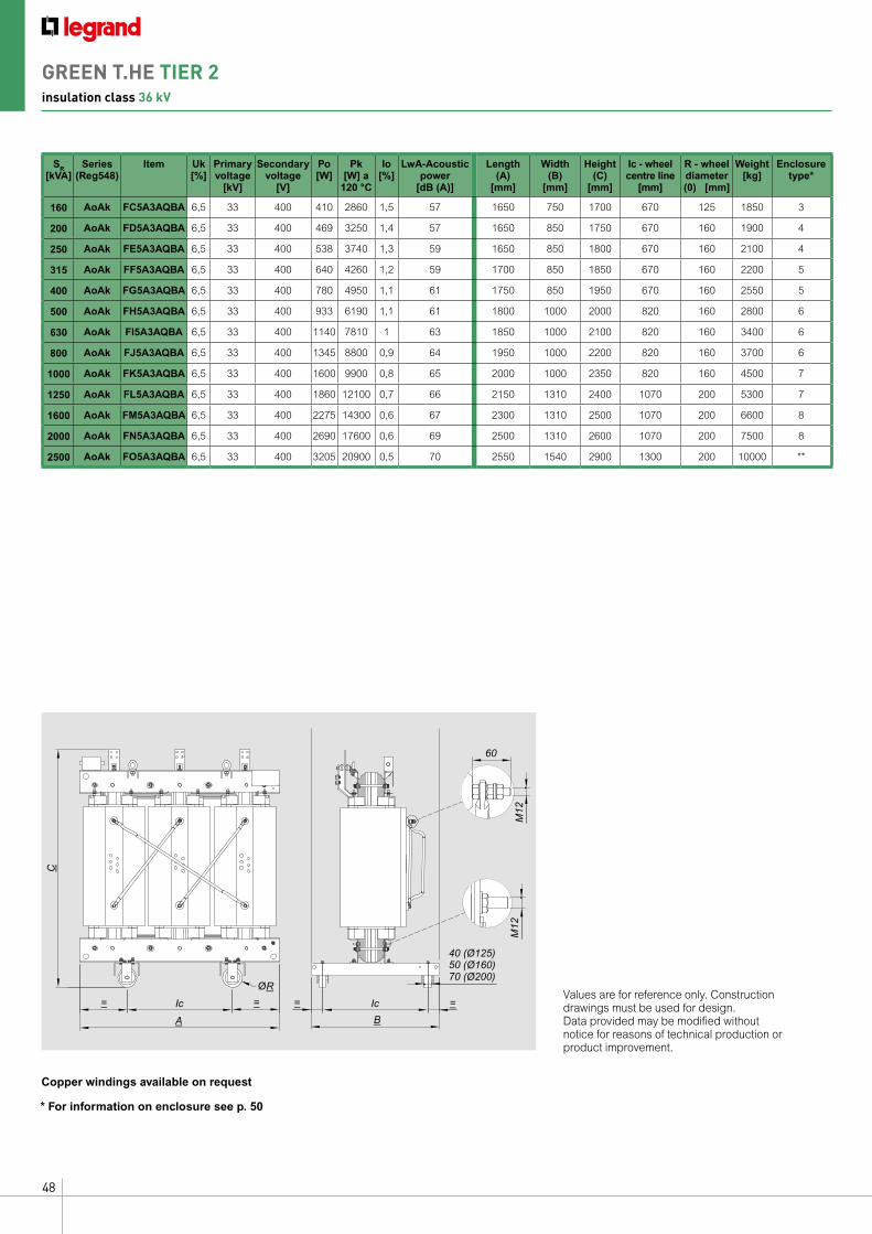
48
A
ØR
=Ic Ic=
C
=
5040 (Ø125)
70 (Ø200) (Ø160)
=
B
60
M12
M12
Values are for reference only. Construction drawings must be used for design. Data provided may be modified without notice for reasons of technical production or product improvement.
SR [kVA]
Series(Reg548)
Item Uk [%]
Primary voltage
[kV]
Secondary voltage
[V]
Po [W]
Pk [W] a
120 °C
Io [%]
LwA-Acoustic power
[dB (A)]
Length(A)
[mm]
Width(B)
[mm]
Height (C)
[mm]
Ic - wheel centre line
[mm]
R - wheel diameter (0) [mm]
Weight [kg]
Enclosuretype*
160 AoAk FC5A3AQBA 6,5 33 400 410 2860 1,5 57 1650 750 1700 670 125 1850 3
200 AoAk FD5A3AQBA 6,5 33 400 469 3250 1,4 57 1650 850 1750 670 160 1900 4
250 AoAk FE5A3AQBA 6,5 33 400 538 3740 1,3 59 1650 850 1800 670 160 2100 4
315 AoAk FF5A3AQBA 6,5 33 400 640 4260 1,2 59 1700 850 1850 670 160 2200 5
400 AoAk FG5A3AQBA 6,5 33 400 780 4950 1,1 61 1750 850 1950 670 160 2550 5
500 AoAk FH5A3AQBA 6,5 33 400 933 6190 1,1 61 1800 1000 2000 820 160 2800 6
630 AoAk FI5A3AQBA 6,5 33 400 1140 7810 1 63 1850 1000 2100 820 160 3400 6
800 AoAk FJ5A3AQBA 6,5 33 400 1345 8800 0,9 64 1950 1000 2200 820 160 3700 6
1000 AoAk FK5A3AQBA 6,5 33 400 1600 9900 0,8 65 2000 1000 2350 820 160 4500 7
1250 AoAk FL5A3AQBA 6,5 33 400 1860 12100 0,7 66 2150 1310 2400 1070 200 5300 7
1600 AoAk FM5A3AQBA 6,5 33 400 2275 14300 0,6 67 2300 1310 2500 1070 200 6600 8
2000 AoAk FN5A3AQBA 6,5 33 400 2690 17600 0,6 69 2500 1310 2600 1070 200 7500 8
2500 AoAk FO5A3AQBA 6,5 33 400 3205 20900 0,5 70 2550 1540 2900 1300 200 10000 **
Copper windings available on request
* For information on enclosure see p. 50
GREEN T.HE TIER 2insulation class 36 kV
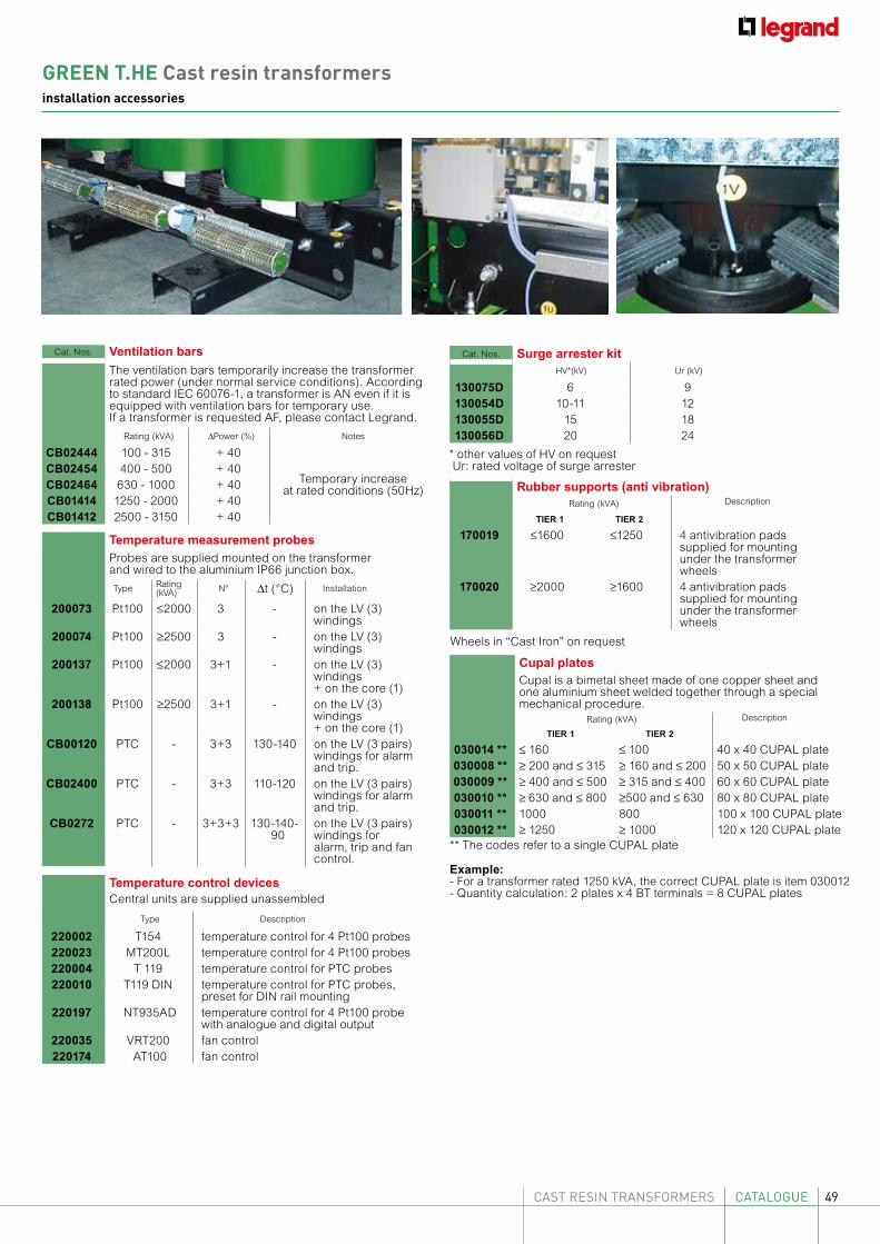
49CAST RESIN TRANSFORMERS CATALOGUE
Cat. Nos. Ventilation bars
The ventilation bars temporarily increase the transformer rated power (under normal service conditions). According to standard IEC 60076-1, a transformer is AN even if it is equipped with ventilation bars for temporary use. If a transformer is requested AF, please contact Legrand.
Rating (kVA) ∆Power (%) Notes
CB02444 100 - 315 + 40
Temporary increase at rated conditions (50Hz)
CB02454 400 - 500 + 40CB02464 630 - 1000 + 40CB01414 1250 - 2000 + 40CB01412 2500 - 3150 + 40
Cat. Nos. Surge arrester kitHV*(kV) Ur (kV)
130075D 6 9130054D 10-11 12130055D 15 18130056D 20 24
Rubber supports (anti vibration)Rating (kVA) Description
TIER 1 TIER 2
170019 ≤1600 ≤1250 4 antivibration pads supplied for mounting under the transformer wheels
170020 ≥2000 ≥1600 4 antivibration pads supplied for mounting under the transformer wheels
Cupal platesCupal is a bimetal sheet made of one copper sheet and one aluminium sheet welded together through a special mechanical procedure.
Rating (kVA) Description
TIER 1 TIER 2
030014 ** ≤ 160 ≤ 100 40 x 40 CUPAL plate030008 ** ≥ 200 and ≤ 315 ≥ 160 and ≤ 200 50 x 50 CUPAL plate030009 ** ≥ 400 and ≤ 500 ≥ 315 and ≤ 400 60 x 60 CUPAL plate030010 ** ≥ 630 and ≤ 800 ≥500 and ≤ 630 80 x 80 CUPAL plate030011 ** 1000 800 100 x 100 CUPAL plate030012 ** ≥ 1250 ≥ 1000 120 x 120 CUPAL plate
** The codes refer to a single CUPAL plate
Example:- For a transformer rated 1250 kVA, the correct CUPAL plate is item 030012- Quantity calculation: 2 plates x 4 BT terminals = 8 CUPAL plates
Temperature measurement probesProbes are supplied mounted on the transformer and wired to the aluminium IP66 junction box.
Type Rating (kVA) N° ∆t (°C) Installation
200073 Pt100 ≤2000 3 - on the LV (3) windings
200074 Pt100 ≥2500 3 - on the LV (3) windings
200137 Pt100 ≤2000 3+1 - on the LV (3) windings+ on the core (1)
200138 Pt100 ≥2500 3+1 - on the LV (3) windings+ on the core (1)
CB00120 PTC - 3+3 130-140 on the LV (3 pairs) windings for alarm and trip.
CB02400 PTC - 3+3 110-120 on the LV (3 pairs) windings for alarm and trip.
CB0272 PTC - 3+3+3 130-140- 90
on the LV (3 pairs) windings for alarm, trip and fan control.
Temperature control devicesCentral units are supplied unassembled
Type Description
220002 T154 temperature control for 4 Pt100 probes220023 MT200L temperature control for 4 Pt100 probes220004 T 119 temperature control for PTC probes220010 T119 DIN temperature control for PTC probes,
preset for DIN rail mounting220197 NT935AD temperature control for 4 Pt100 probe
with analogue and digital output220035 VRT200 fan control220174 AT100 fan control
* other values of HV on request Ur: rated voltage of surge arrester
Wheels in “Cast Iron” on request
GREEN T.HE Cast resin transformersinstallation accessories
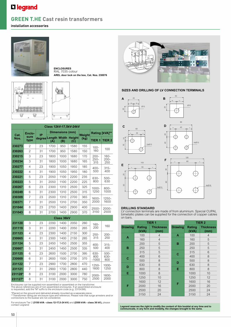
50
ENCLOSURESRAL 7035 colourAREL door lock on the box, Cat. Nos. 230076
SIZES AND DRILLING OF LV CONNECTION TERMINALS
A
C
B
40
20
A= =
Ø13Ø15
50
25
B= =
32
32
C
= =
2xØ13
14
6040
40
D= =
4xØ13
20
80
120
TIER 1
Drawing Rating (kVA)
Thickness (mm)
A100 4160 4
B200 5250 5315 5
C400 6500 8
D630 8800 8
E 1000 8
F
1250 101600 122000 162500 203150 24
50
50
E= =
25
10060
60
F= =
4xØ18
30
4xØ15
Legrand reserves the right to modify the content of this booklet at any time and to communicate, in any form and modality, the changes brought to the same.
Class 12kV-17,5kV-24kV
Cat.Nos.
Enclo-sure type
IP degree
Dimensions (mm)Weight
(kg)
Rating [kVA]**
Length (A)
Width(B)
Height(C) TIER 1 TIER 2
230273 2 23 1700 950 1580 155 100-160 100
230263 2 31 1700 950 1580 150
230215 3 23 1800 1000 1680 170 200-250-315
160-200-250230234 3 31 1800 1000 1680 165
230277 4 23 1900 1050 1950 185 400-500
315-400230222 4 31 1900 1050 1950 180
230221 5 23 2050 1100 2200 235 630-800
500-630230223 5 31 2050 1100 2200 225
230267 6 23 2300 1310 2500 325 1000-1250
800-1000230249 6 31 2300 1310 2500 315
230309 7 23 2500 1310 2700 365 1600- 2000
1250-1600230371 7 31 2500 1310 2700 350
231044 8 23 2700 1400 2900 400 2500- 3150
2000-2500231043 8 31 2700 1400 2900 370
Class 36kV
231120 3 23 2200 1400 2050 280 160-200 160
231119 3 31 2200 1400 2050 265
231123 4 23 2300 1400 2150 300 250-315
200-250230665 4 31 2300 1400 2150 285
231124 5 23 2450 1450 2500 355 400-500
315-400230667 5 31 2450 1450 2500 335
231125 6 23 2600 1500 2700 395 630-800
-1000
500-630-800230669 6 31 2600 1500 2700 370
231122 7 23 2900 1700 2800 470 1250-1600
1000-1250231121 7 31 2900 1700 2800 440
231128* 8 23 3100 2000 3000 780 2000- 2500
1600-2000231127* 8 31 3100 2000 3000 750
*Placed on the ground and delivered already mounted as a separate piece.**Transformer rating per enclosure type and reference. Please note that surge arresters and/or connections to the busbar are not considered.
For enclosure Tier 2 (3150 kVA - class 12-17,5-24 kV) and (2500 kVA - class 36 kV), please contact Legrand
DRILLING STANDARDLV connection terminals are made of from aluminium. Special CUPAL bimetallic plates can be supplied for the connection of copper cables on bars.
TIER 2
Drawing Rating (kVA)
Thickness (mm)
A 100 4
B160 5200 5250 5
C315 6400 8
D500 8630 8
E 800 8
F
1000 101250 121600 162000 202500 243150 24
Enclosures can be supplied non-assembled or assembled on the transformer.The above references are of non-assembled enclosures. If an assembled enclosure is requested, add the "M" suffix to the enclosure code (e.g. 231043M).
GREEN T.HE Cast resin transformersinstallation accessories
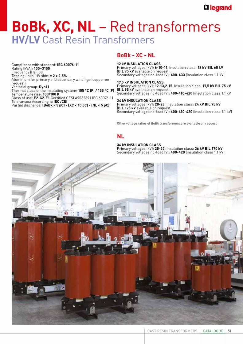
51CAST RESIN TRANSFORMERS CATALOGUE
BoBk - XC - NL12 kV INSULATION CLASSPrimary voltages (kV): 6-10-11. Insulation class: 12 kV BIL 60 kV(BIL 75 kV available on request). Secondary voltages no-load (V): 400-433 (insulation class 1.1 kV)
17,5 kV INSULATION CLASSPrimary voltages (kV): 12-13,2-15. Insulation class: 17,5 kV BIL 75 kV(BIL 95 kV available on request).Secondary voltages no-load (V): 400-410-420 (insulation class 1.1 kV
24 kV INSULATION CLASSPrimary voltages (kV): 20-23. Insulation class: 24 kV BIL 95 kV(BIL 125 kV available on request).Secondary voltages no-load (V): 400-410-420 (insulation class 1.1 kV)
NL36 kV INSULATION CLASSPrimary voltages (kV): 25-33. Insulation class: 36 kV BIL 170 kVSecondary voltages no-load (V): 400-420 (insulation class 1.1 kV)
BoBk, XC, NL – Red transformersHV/LV Cast Resin Transformers
Other voltage ratios of BoBk transformers are available on request
Compliance with standard: IEC 60076-11 Rating (kVA): 100–3150Frequency (Hz): 50Tapping links, HV side: ± 2 x 2.5%Aluminium for primary and secondary windings (copper on request)Vectorial group: Dyn11Thermal class of the insulating system: 155 °C (F) / 155 °C (F)Temperature rise: 100/100 KClass of use: E2-C2-F1 Certified CESI A9032391 IEC 60076-11Tolerances: According to IEC /CEIPartial discharge: (BoBk < 5 pC) - (XC < 10 pC) - (NL < 5 pC)
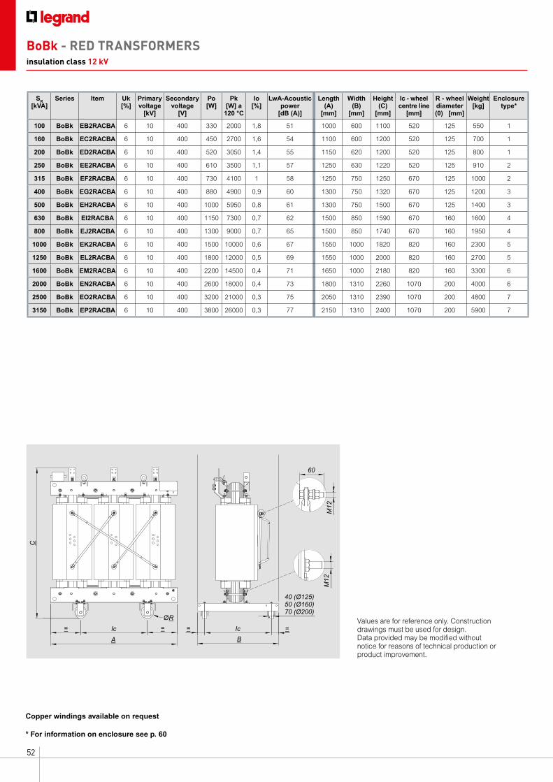
52
SR [kVA]
Series Item Uk [%]
Primary voltage
[kV]
Secondary voltage
[V]
Po [W]
Pk [W] a
120 °C
Io [%]
LwA-Acoustic power
[dB (A)]
Length(A)
[mm]
Width(B)
[mm]
Height (C)
[mm]
Ic - wheel centre line
[mm]
R - wheel diameter (0) [mm]
Weight [kg]
Enclosuretype*
100 BoBk EB2RACBA 6 10 400 330 2000 1,8 51 1000 600 1100 520 125 550 1
160 BoBk EC2RACBA 6 10 400 450 2700 1,6 54 1100 600 1200 520 125 700 1
200 BoBk ED2RACBA 6 10 400 520 3050 1,4 55 1150 620 1200 520 125 800 1
250 BoBk EE2RACBA 6 10 400 610 3500 1,1 57 1250 630 1220 520 125 910 2
315 BoBk EF2RACBA 6 10 400 730 4100 1 58 1250 750 1250 670 125 1000 2
400 BoBk EG2RACBA 6 10 400 880 4900 0,9 60 1300 750 1320 670 125 1200 3
500 BoBk EH2RACBA 6 10 400 1000 5950 0,8 61 1300 750 1500 670 125 1400 3
630 BoBk EI2RACBA 6 10 400 1150 7300 0,7 62 1500 850 1590 670 160 1600 4
800 BoBk EJ2RACBA 6 10 400 1300 9000 0,7 65 1500 850 1740 670 160 1950 4
1000 BoBk EK2RACBA 6 10 400 1500 10000 0,6 67 1550 1000 1820 820 160 2300 5
1250 BoBk EL2RACBA 6 10 400 1800 12000 0,5 69 1550 1000 2000 820 160 2700 5
1600 BoBk EM2RACBA 6 10 400 2200 14500 0,4 71 1650 1000 2180 820 160 3300 6
2000 BoBk EN2RACBA 6 10 400 2600 18000 0,4 73 1800 1310 2260 1070 200 4000 6
2500 BoBk EO2RACBA 6 10 400 3200 21000 0,3 75 2050 1310 2390 1070 200 4800 7
3150 BoBk EP2RACBA 6 10 400 3800 26000 0,3 77 2150 1310 2400 1070 200 5900 7
* For information on enclosure see p. 60
Copper windings available on request
BoBk - RED TRANSFORMERSinsulation class 12 kV
A
ØR
=Ic Ic=
C
=
5040 (Ø125)
70 (Ø200) (Ø160)
=
B
60
M12
M12
Values are for reference only. Construction drawings must be used for design. Data provided may be modified without notice for reasons of technical production or product improvement.
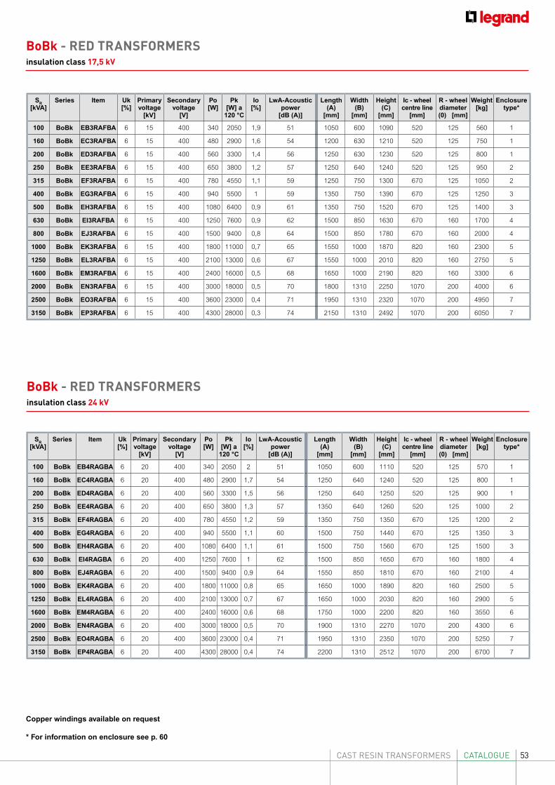
53CAST RESIN TRANSFORMERS CATALOGUE
* For information on enclosure see p. 60
Copper windings available on request
SR [kVA]
Series Item Uk [%]
Primary voltage
[kV]
Secondary voltage
[V]
Po [W]
Pk [W] a
120 °C
Io [%]
LwA-Acoustic power
[dB (A)]
Length(A)
[mm]
Width(B)
[mm]
Height (C)
[mm]
Ic - wheel centre line
[mm]
R - wheel diameter (0) [mm]
Weight [kg]
Enclosuretype*
100 BoBk EB4RAGBA 6 20 400 340 2050 2 51 1050 600 1110 520 125 570 1
160 BoBk EC4RAGBA 6 20 400 480 2900 1,7 54 1250 640 1240 520 125 800 1
200 BoBk ED4RAGBA 6 20 400 560 3300 1,5 56 1250 640 1250 520 125 900 1
250 BoBk EE4RAGBA 6 20 400 650 3800 1,3 57 1350 640 1260 520 125 1000 2
315 BoBk EF4RAGBA 6 20 400 780 4550 1,2 59 1350 750 1350 670 125 1200 2
400 BoBk EG4RAGBA 6 20 400 940 5500 1,1 60 1500 750 1440 670 125 1350 3
500 BoBk EH4RAGBA 6 20 400 1080 6400 1,1 61 1500 750 1560 670 125 1500 3
630 BoBk EI4RAGBA 6 20 400 1250 7600 1 62 1500 850 1650 670 160 1800 4
800 BoBk EJ4RAGBA 6 20 400 1500 9400 0,9 64 1550 850 1810 670 160 2100 4
1000 BoBk EK4RAGBA 6 20 400 1800 11000 0,8 65 1650 1000 1890 820 160 2500 5
1250 BoBk EL4RAGBA 6 20 400 2100 13000 0,7 67 1650 1000 2030 820 160 2900 5
1600 BoBk EM4RAGBA 6 20 400 2400 16000 0,6 68 1750 1000 2200 820 160 3550 6
2000 BoBk EN4RAGBA 6 20 400 3000 18000 0,5 70 1900 1310 2270 1070 200 4300 6
2500 BoBk EO4RAGBA 6 20 400 3600 23000 0,4 71 1950 1310 2350 1070 200 5250 7
3150 BoBk EP4RAGBA 6 20 400 4300 28000 0,4 74 2200 1310 2512 1070 200 6700 7
BoBk - RED TRANSFORMERSinsulation class 24 kV
SR [kVA]
Series Item Uk [%]
Primary voltage
[kV]
Secondary voltage
[V]
Po [W]
Pk [W] a
120 °C
Io [%]
LwA-Acoustic power
[dB (A)]
Length(A)
[mm]
Width(B)
[mm]
Height (C)
[mm]
Ic - wheel centre line
[mm]
R - wheel diameter (0) [mm]
Weight [kg]
Enclosuretype*
100 BoBk EB3RAFBA 6 15 400 340 2050 1,9 51 1050 600 1090 520 125 560 1
160 BoBk EC3RAFBA 6 15 400 480 2900 1,6 54 1200 630 1210 520 125 750 1
200 BoBk ED3RAFBA 6 15 400 560 3300 1,4 56 1250 630 1230 520 125 800 1
250 BoBk EE3RAFBA 6 15 400 650 3800 1,2 57 1250 640 1240 520 125 950 2
315 BoBk EF3RAFBA 6 15 400 780 4550 1,1 59 1250 750 1300 670 125 1050 2
400 BoBk EG3RAFBA 6 15 400 940 5500 1 59 1350 750 1390 670 125 1250 3
500 BoBk EH3RAFBA 6 15 400 1080 6400 0,9 61 1350 750 1520 670 125 1400 3
630 BoBk EI3RAFBA 6 15 400 1250 7600 0,9 62 1500 850 1630 670 160 1700 4
800 BoBk EJ3RAFBA 6 15 400 1500 9400 0,8 64 1500 850 1780 670 160 2000 4
1000 BoBk EK3RAFBA 6 15 400 1800 11000 0,7 65 1550 1000 1870 820 160 2300 5
1250 BoBk EL3RAFBA 6 15 400 2100 13000 0,6 67 1550 1000 2010 820 160 2750 5
1600 BoBk EM3RAFBA 6 15 400 2400 16000 0,5 68 1650 1000 2190 820 160 3300 6
2000 BoBk EN3RAFBA 6 15 400 3000 18000 0,5 70 1800 1310 2250 1070 200 4000 6
2500 BoBk EO3RAFBA 6 15 400 3600 23000 0,4 71 1950 1310 2320 1070 200 4950 7
3150 BoBk EP3RAFBA 6 15 400 4300 28000 0,3 74 2150 1310 2492 1070 200 6050 7
BoBk - RED TRANSFORMERSinsulation class 17,5 kV
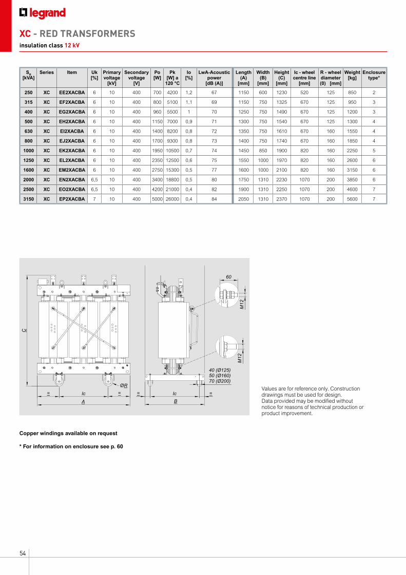
54
A
ØR
=Ic Ic=
C
=
5040 (Ø125)
70 (Ø200) (Ø160)
=
B
60
M12
M12
Values are for reference only. Construction drawings must be used for design. Data provided may be modified without notice for reasons of technical production or product improvement.
SR [kVA]
Series Item Uk [%]
Primary voltage
[kV]
Secondary voltage
[V]
Po [W]
Pk [W] a
120 °C
Io [%]
LwA-Acoustic power
[dB (A)]
Length(A)
[mm]
Width(B)
[mm]
Height (C)
[mm]
Ic - wheel centre line
[mm]
R - wheel diameter (0) [mm]
Weight [kg]
Enclosuretype*
250 XC EE2XACBA 6 10 400 700 4200 1,2 67 1150 600 1230 520 125 850 2
315 XC EF2XACBA 6 10 400 800 5100 1,1 69 1150 750 1325 670 125 950 3
400 XC EG2XACBA 6 10 400 960 5500 1 70 1250 750 1490 670 125 1200 3
500 XC EH2XACBA 6 10 400 1150 7000 0,9 71 1300 750 1540 670 125 1300 4
630 XC EI2XACBA 6 10 400 1400 8200 0,8 72 1350 750 1610 670 160 1550 4
800 XC EJ2XACBA 6 10 400 1700 9300 0,8 73 1400 750 1740 670 160 1850 4
1000 XC EK2XACBA 6 10 400 1950 10500 0,7 74 1450 850 1900 820 160 2250 5
1250 XC EL2XACBA 6 10 400 2350 12500 0,6 75 1550 1000 1970 820 160 2600 6
1600 XC EM2XACBA 6 10 400 2750 15300 0,5 77 1600 1000 2100 820 160 3150 6
2000 XC EN2XACBA 6,5 10 400 3400 18800 0,5 80 1750 1310 2230 1070 200 3850 6
2500 XC EO2XACBA 6,5 10 400 4200 21000 0,4 82 1900 1310 2250 1070 200 4600 7
3150 XC EP2XACBA 7 10 400 5000 26000 0,4 84 2050 1310 2370 1070 200 5600 7
XC - RED TRANSFORMERSinsulation class 12 kV
* For information on enclosure see p. 60
Copper windings available on request
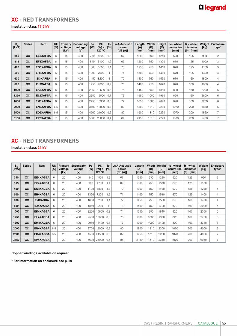
55CAST RESIN TRANSFORMERS CATALOGUE
SR [kVA]
Series Item Uk [%]
Primary voltage
[kV]
Secondary voltage
[V]
Po [W]
Pk [W] a
120 °C
Io [%]
LwA-Acoustic power
[dB (A)]
Length(A)
[mm]
Width(B)
[mm]
Height (C)
[mm]
Ic - wheel centre line
[mm]
R - wheel diameter (0) [mm]
Weight [kg]
Enclosuretype*
250 XC EE4XAGBA 6 20 400 840 4500 1,5 67 1250 630 1280 520 125 950 2
315 XC EF4XAGBA 6 20 400 990 4700 1,4 69 1300 750 1370 670 125 1100 3
400 XC EG4XAGBA 6 20 400 1100 5800 1,3 70 1350 750 1460 670 125 1250 4
500 XC EH4XAGBA 6 20 400 1320 7200 1,2 71 1400 750 1510 670 125 1400 4
630 XC EI4XAGBA 6 20 400 1600 8200 1,1 72 1450 750 1580 670 160 1700 4
800 XC EJ4XAGBA 6 20 400 1880 9200 1 73 1500 750 1720 670 160 2000 5
1000 XC EK4XAGBA 6 20 400 2250 10600 0,9 74 1550 850 1840 820 160 2350 5
1250 XC EL4XAGBA 6 20 400 2500 12800 0,8 75 1600 1000 1990 820 160 2750 6
1600 XC EM4XAGBA 6 20 400 2980 15400 0,7 77 1700 1000 2120 820 160 3350 6
2000 XC EN4XAGBA 6,5 20 400 3700 19000 0,6 80 1800 1310 2200 1070 200 4000 6
2500 XC EO4XAGBA 6,5 20 400 4500 21500 0,5 82 1950 1310 2280 1070 200 4900 7
3150 XC EP4XAGBA 7 20 400 5600 26000 0,5 85 2150 1310 2340 1070 200 6050 7
SR [kVA]
Series Item Uk [%]
Primary voltage
[kV]
Secondary voltage
[V]
Po [W]
Pk [W] a
120 °C
Io [%]
LwA-Acoustic power
[dB (A)]
Length(A)
[mm]
Width(B)
[mm]
Height (C)
[mm]
Ic - wheel centre line
[mm]
R - wheel diameter (0) [mm]
Weight [kg]
Enclosuretype*
250 XC EE3XAFBA 6 15 400 730 4200 1,3 67 1200 600 1240 520 125 900 2
315 XC EF3XAFBA 6 15 400 840 5100 1,2 69 1200 750 1320 670 125 1000 3
400 XC EG3XAFBA 6 15 400 1000 5500 1,1 70 1250 750 1410 670 125 1150 3
500 XC EH3XAFBA 6 15 400 1200 7000 1 71 1300 750 1460 670 125 1300 4
630 XC EI3XAFBA 6 15 400 1450 8200 1 72 1400 750 1530 670 160 1600 4
800 XC EJ3XAFBA 6 15 400 1750 9300 0,9 73 1400 750 1670 670 160 1850 4
1000 XC EK3XAFBA 6 15 400 2050 10500 0,8 74 1450 850 1810 820 160 2200 5
1250 XC EL3XAFBA 6 15 400 2350 12500 0,7 75 1550 1000 1960 820 160 2600 6
1600 XC EM3XAFBA 6 15 400 2750 15300 0,6 77 1650 1000 2090 820 160 3200 6
2000 XC EN3XAFBA 6,5 15 400 3400 18800 0,6 80 1800 1310 2200 1070 200 3850 6
2500 XC EO3XAFBA 6,5 15 400 4200 21000 0,5 82 1900 1310 2230 1070 200 4650 7
3150 XC EP3XAFBA 7 15 400 5000 26000 0,4 84 2150 1310 2290 1070 200 5700 7
XC - RED TRANSFORMERSinsulation class 17,5 kV
XC - RED TRANSFORMERSinsulation class 24 kV
* For information on enclosure see p. 60
Copper windings available on request
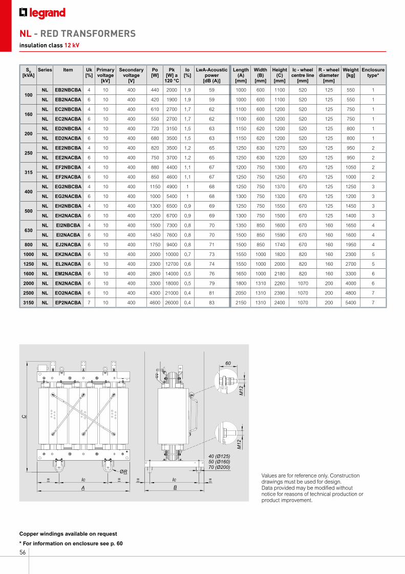
56
SR [kVA]
Series Item Uk [%]
Primary voltage
[kV]
Secondary voltage
[V]
Po [W]
Pk [W] a
120 °C
Io [%]
LwA-Acoustic power
[dB (A)]
Length(A)
[mm]
Width(B)
[mm]
Height (C)
[mm]
Ic - wheel centre line
[mm]
R - wheel diameter
[mm]
Weight [kg]
Enclosuretype*
100NL EB2NBCBA 4 10 400 440 2000 1,9 59 1000 600 1100 520 125 550 1
NL EB2NACBA 6 10 400 420 1900 1,9 59 1000 600 1100 520 125 550 1
160NL EC2NBCBA 4 10 400 610 2700 1,7 62 1100 600 1200 520 125 750 1
NL EC2NACBA 6 10 400 550 2700 1,7 62 1100 600 1200 520 125 750 1
200NL ED2NBCBA 4 10 400 720 3150 1,5 63 1150 620 1200 520 125 800 1
NL ED2NACBA 6 10 400 680 3500 1,5 63 1150 620 1200 520 125 800 1
250NL EE2NBCBA 4 10 400 820 3500 1,2 65 1250 630 1270 520 125 950 2
NL EE2NACBA 6 10 400 750 3700 1,2 65 1250 630 1220 520 125 950 2
315NL EF2NBCBA 4 10 400 880 4400 1,1 67 1200 750 1300 670 125 1050 2
NL EF2NACBA 6 10 400 850 4600 1,1 67 1250 750 1250 670 125 1000 2
400NL EG2NBCBA 4 10 400 1150 4900 1 68 1250 750 1370 670 125 1250 3
NL EG2NACBA 6 10 400 1000 5400 1 68 1300 750 1320 670 125 1200 3
500NL EH2NBCBA 4 10 400 1300 6500 0,9 69 1250 750 1550 670 125 1450 3
NL EH2NACBA 6 10 400 1200 6700 0,9 69 1300 750 1500 670 125 1400 3
630NL EI2NBCBA 4 10 400 1500 7300 0,8 70 1350 850 1600 670 160 1650 4
NL EI2NACBA 6 10 400 1450 7600 0,8 70 1500 850 1590 670 160 1600 4
800 NL EJ2NACBA 6 10 400 1750 9400 0,8 71 1500 850 1740 670 160 1950 4
1000 NL EK2NACBA 6 10 400 2000 10000 0,7 73 1550 1000 1820 820 160 2300 5
1250 NL EL2NACBA 6 10 400 2300 12700 0,6 74 1550 1000 2000 820 160 2700 5
1600 NL EM2NACBA 6 10 400 2800 14000 0,5 76 1650 1000 2180 820 160 3300 6
2000 NL EN2NACBA 6 10 400 3300 18000 0,5 79 1800 1310 2260 1070 200 4000 6
2500 NL EO2NACBA 6 10 400 4300 21000 0,4 81 2050 1310 2390 1070 200 4800 7
3150 NL EP2NACBA 7 10 400 4600 26000 0,4 83 2150 1310 2400 1070 200 5400 7
NL - RED TRANSFORMERSinsulation class 12 kV
* For information on enclosure see p. 60
Copper windings available on request
A
ØR
=Ic Ic=
C
=
5040 (Ø125)
70 (Ø200) (Ø160)
=
B
60
M12
M12
Values are for reference only. Construction drawings must be used for design. Data provided may be modified without notice for reasons of technical production or product improvement.
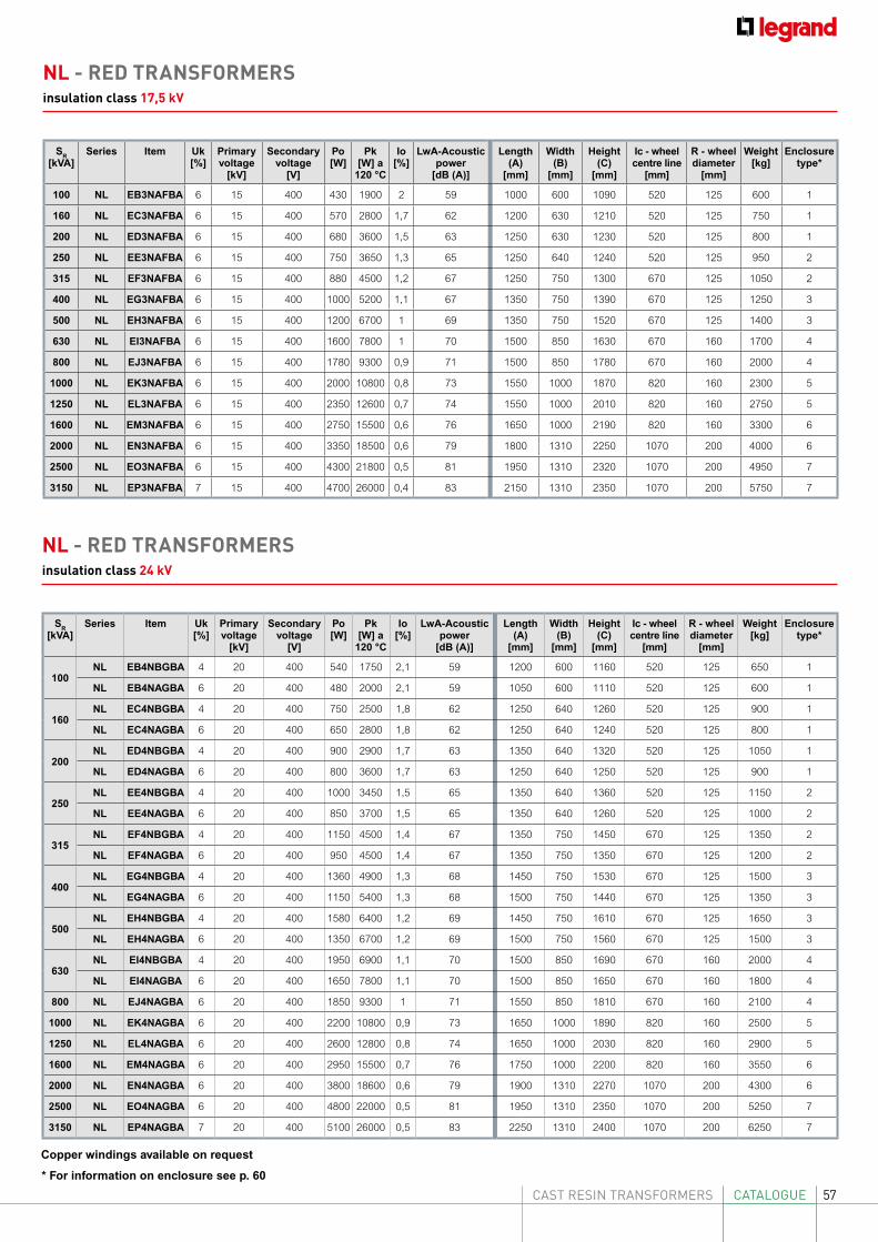
57CAST RESIN TRANSFORMERS CATALOGUE* For information on enclosure see p. 60
Copper windings available on request
SR [kVA]
Series Item Uk [%]
Primary voltage
[kV]
Secondary voltage
[V]
Po [W]
Pk [W] a
120 °C
Io [%]
LwA-Acoustic power
[dB (A)]
Length(A)
[mm]
Width(B)
[mm]
Height (C)
[mm]
Ic - wheel centre line
[mm]
R - wheel diameter
[mm]
Weight [kg]
Enclosuretype*
100NL EB4NBGBA 4 20 400 540 1750 2,1 59 1200 600 1160 520 125 650 1
NL EB4NAGBA 6 20 400 480 2000 2,1 59 1050 600 1110 520 125 600 1
160NL EC4NBGBA 4 20 400 750 2500 1,8 62 1250 640 1260 520 125 900 1
NL EC4NAGBA 6 20 400 650 2800 1,8 62 1250 640 1240 520 125 800 1
200NL ED4NBGBA 4 20 400 900 2900 1,7 63 1350 640 1320 520 125 1050 1
NL ED4NAGBA 6 20 400 800 3600 1,7 63 1250 640 1250 520 125 900 1
250NL EE4NBGBA 4 20 400 1000 3450 1,5 65 1350 640 1360 520 125 1150 2
NL EE4NAGBA 6 20 400 850 3700 1,5 65 1350 640 1260 520 125 1000 2
315NL EF4NBGBA 4 20 400 1150 4500 1,4 67 1350 750 1450 670 125 1350 2
NL EF4NAGBA 6 20 400 950 4500 1,4 67 1350 750 1350 670 125 1200 2
400NL EG4NBGBA 4 20 400 1360 4900 1,3 68 1450 750 1530 670 125 1500 3
NL EG4NAGBA 6 20 400 1150 5400 1,3 68 1500 750 1440 670 125 1350 3
500NL EH4NBGBA 4 20 400 1580 6400 1,2 69 1450 750 1610 670 125 1650 3
NL EH4NAGBA 6 20 400 1350 6700 1,2 69 1500 750 1560 670 125 1500 3
630NL EI4NBGBA 4 20 400 1950 6900 1,1 70 1500 850 1690 670 160 2000 4
NL EI4NAGBA 6 20 400 1650 7800 1,1 70 1500 850 1650 670 160 1800 4
800 NL EJ4NAGBA 6 20 400 1850 9300 1 71 1550 850 1810 670 160 2100 4
1000 NL EK4NAGBA 6 20 400 2200 10800 0,9 73 1650 1000 1890 820 160 2500 5
1250 NL EL4NAGBA 6 20 400 2600 12800 0,8 74 1650 1000 2030 820 160 2900 5
1600 NL EM4NAGBA 6 20 400 2950 15500 0,7 76 1750 1000 2200 820 160 3550 6
2000 NL EN4NAGBA 6 20 400 3800 18600 0,6 79 1900 1310 2270 1070 200 4300 6
2500 NL EO4NAGBA 6 20 400 4800 22000 0,5 81 1950 1310 2350 1070 200 5250 7
3150 NL EP4NAGBA 7 20 400 5100 26000 0,5 83 2250 1310 2400 1070 200 6250 7
NL - RED TRANSFORMERSinsulation class 24 kV
SR [kVA]
Series Item Uk [%]
Primary voltage
[kV]
Secondary voltage
[V]
Po [W]
Pk [W] a
120 °C
Io [%]
LwA-Acoustic power
[dB (A)]
Length(A)
[mm]
Width(B)
[mm]
Height (C)
[mm]
Ic - wheel centre line
[mm]
R - wheel diameter
[mm]
Weight [kg]
Enclosuretype*
100 NL EB3NAFBA 6 15 400 430 1900 2 59 1000 600 1090 520 125 600 1
160 NL EC3NAFBA 6 15 400 570 2800 1,7 62 1200 630 1210 520 125 750 1
200 NL ED3NAFBA 6 15 400 680 3600 1,5 63 1250 630 1230 520 125 800 1
250 NL EE3NAFBA 6 15 400 750 3650 1,3 65 1250 640 1240 520 125 950 2
315 NL EF3NAFBA 6 15 400 880 4500 1,2 67 1250 750 1300 670 125 1050 2
400 NL EG3NAFBA 6 15 400 1000 5200 1,1 67 1350 750 1390 670 125 1250 3
500 NL EH3NAFBA 6 15 400 1200 6700 1 69 1350 750 1520 670 125 1400 3
630 NL EI3NAFBA 6 15 400 1600 7800 1 70 1500 850 1630 670 160 1700 4
800 NL EJ3NAFBA 6 15 400 1780 9300 0,9 71 1500 850 1780 670 160 2000 4
1000 NL EK3NAFBA 6 15 400 2000 10800 0,8 73 1550 1000 1870 820 160 2300 5
1250 NL EL3NAFBA 6 15 400 2350 12600 0,7 74 1550 1000 2010 820 160 2750 5
1600 NL EM3NAFBA 6 15 400 2750 15500 0,6 76 1650 1000 2190 820 160 3300 6
2000 NL EN3NAFBA 6 15 400 3350 18500 0,6 79 1800 1310 2250 1070 200 4000 6
2500 NL EO3NAFBA 6 15 400 4300 21800 0,5 81 1950 1310 2320 1070 200 4950 7
3150 NL EP3NAFBA 7 15 400 4700 26000 0,4 83 2150 1310 2350 1070 200 5750 7
NL - RED TRANSFORMERSinsulation class 17,5 kV
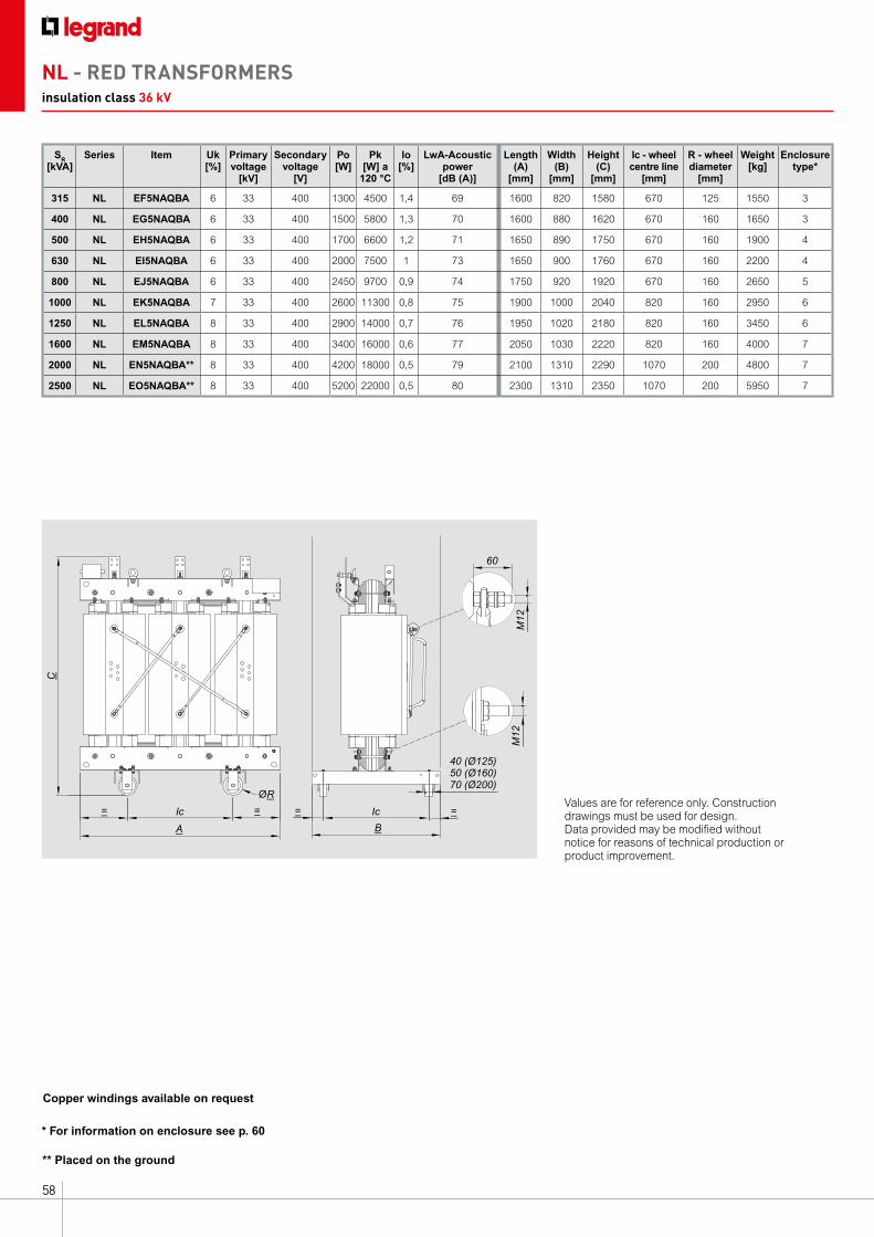
58
SR [kVA]
Series Item Uk [%]
Primary voltage
[kV]
Secondary voltage
[V]
Po [W]
Pk [W] a
120 °C
Io [%]
LwA-Acoustic power
[dB (A)]
Length(A)
[mm]
Width(B)
[mm]
Height (C)
[mm]
Ic - wheel centre line
[mm]
R - wheel diameter
[mm]
Weight [kg]
Enclosuretype*
315 NL EF5NAQBA 6 33 400 1300 4500 1,4 69 1600 820 1580 670 125 1550 3
400 NL EG5NAQBA 6 33 400 1500 5800 1,3 70 1600 880 1620 670 160 1650 3
500 NL EH5NAQBA 6 33 400 1700 6600 1,2 71 1650 890 1750 670 160 1900 4
630 NL EI5NAQBA 6 33 400 2000 7500 1 73 1650 900 1760 670 160 2200 4
800 NL EJ5NAQBA 6 33 400 2450 9700 0,9 74 1750 920 1920 670 160 2650 5
1000 NL EK5NAQBA 7 33 400 2600 11300 0,8 75 1900 1000 2040 820 160 2950 6
1250 NL EL5NAQBA 8 33 400 2900 14000 0,7 76 1950 1020 2180 820 160 3450 6
1600 NL EM5NAQBA 8 33 400 3400 16000 0,6 77 2050 1030 2220 820 160 4000 7
2000 NL EN5NAQBA** 8 33 400 4200 18000 0,5 79 2100 1310 2290 1070 200 4800 7
2500 NL EO5NAQBA** 8 33 400 5200 22000 0,5 80 2300 1310 2350 1070 200 5950 7
* For information on enclosure see p. 60
Copper windings available on request
** Placed on the ground
A
ØR
=Ic Ic=
C
=
5040 (Ø125)
70 (Ø200) (Ø160)
=
B
60
M12
M12
Values are for reference only. Construction drawings must be used for design. Data provided may be modified without notice for reasons of technical production or product improvement.
NL - RED TRANSFORMERSinsulation class 36 kV
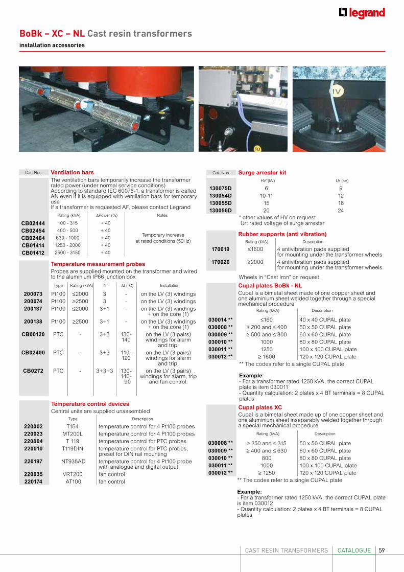
59CAST RESIN TRANSFORMERS CATALOGUE
Cat. Nos. Ventilation barsThe ventilation bars temporarily increase the transformer rated power (under normal service conditions)According to standard IEC 60076-1, a transformer is called AN even if it is equipped with ventilation bars for temporary useIf a transformer is requested AF, please contact Legrand
Rating (kVA) ∆Power (%) Notes
CB02444 100 - 315 + 40
Temporary increase at rated conditions (50Hz)
CB02454 400 - 500 + 40
CB02464 630 - 1000 + 40
CB01414 1250 - 2000 + 40
CB01412 2500 - 3150 + 40
Cat. Nos. Surge arrester kitHV*(kV) Ur (kV)
130075D 6 9130054D 10-11 12130055D 15 18130056D 20 24
Rubber supports (anti vibration)Rating (kVA) Description
170019 ≤1600 4 antivibration pads suppliedfor mounting under the transformer wheels
170020 ≥2000 4 antivibration pads suppliedfor mounting under the transformer wheels
Cupal plates BoBk - NLCupal is a bimetal sheet made of one copper sheet and one aluminium sheet welded together through a special mechanical procedure
Rating (kVA) Description
030014 ** ≤160 40 x 40 CUPAL plate030008 ** ≥ 200 and ≤ 400 50 x 50 CUPAL plate030009 ** ≥ 500 and ≤ 800 60 x 60 CUPAL plate030010 ** 1000 80 x 80 CUPAL plate030011 ** 1250 100 x 100 CUPAL plate030012 ** ≥ 1600 120 x 120 CUPAL plate
** The codes refer to a single CUPAL plate
Example:- For a transformer rated 1250 kVA, the correct CUPAL plate is item 030011- Quantity calculation: 2 plates x 4 BT terminals = 8 CUPAL plates
Temperature measurement probesProbes are supplied mounted on the transformer and wiredto the aluminium IP66 junction box
Type Rating (kVA) N° ∆t (°C) Installation
200073 Pt100 ≤2000 3 - on the LV (3) windings200074 Pt100 ≥2500 3 - on the LV (3) windings200137 Pt100 ≤2000 3+1 - on the LV (3) windings
+ on the core (1)200138 Pt100 ≥2500 3+1 - on the LV (3) windings
+ on the core (1)CB00120 PTC - 3+3 130-
140on the LV (3 pairs) windings for alarm
and trip. CB02400 PTC - 3+3 110-
120on the LV (3 pairs) windings for alarm
and trip.CB0272 PTC - 3+3+3 130-
140- 90
on the LV (3 pairs) windings for alarm, trip
and fan control.
Temperature control devicesCentral units are supplied unassembled
Type Description
220002 T154 temperature control for 4 Pt100 probes220023 MT200L temperature control for 4 Pt100 probes220004 T 119 temperature control for PTC probes220010 T119DIN temperature control for PTC probes,
preset for DIN rail mounting220197 NT935AD temperature control for 4 Pt100 probe
with analogue and digital output220035 VRT200 fan control220174 AT100 fan control
* other values of HV on request Ur: rated voltage of surge arrester
Cupal plates XCCupal is a bimetal sheet made up of one copper sheet and one aluminium sheet inseparably welded together through a special mechanical procedure
Rating (kVA) Description
030008 ** ≥ 250 and ≤ 315 50 x 50 CUPAL plate030009 ** ≥ 400 and ≤ 630 60 x 60 CUPAL plate030010 ** 800 80 x 80 CUPAL plate030011 ** 1000 100 x 100 CUPAL plate030012 ** ≥ 1250 120 x 120 CUPAL plate
** The codes refer to a single CUPAL plate
Example:- For a transformer rated 1250 kVA, the correct CUPAL plate is item 030012- Quantity calculation: 2 plates x 4 BT terminals = 8 CUPAL plates
Wheels in “Cast Iron” on request
BoBk – XC – NL Cast resin transformersinstallation accessories
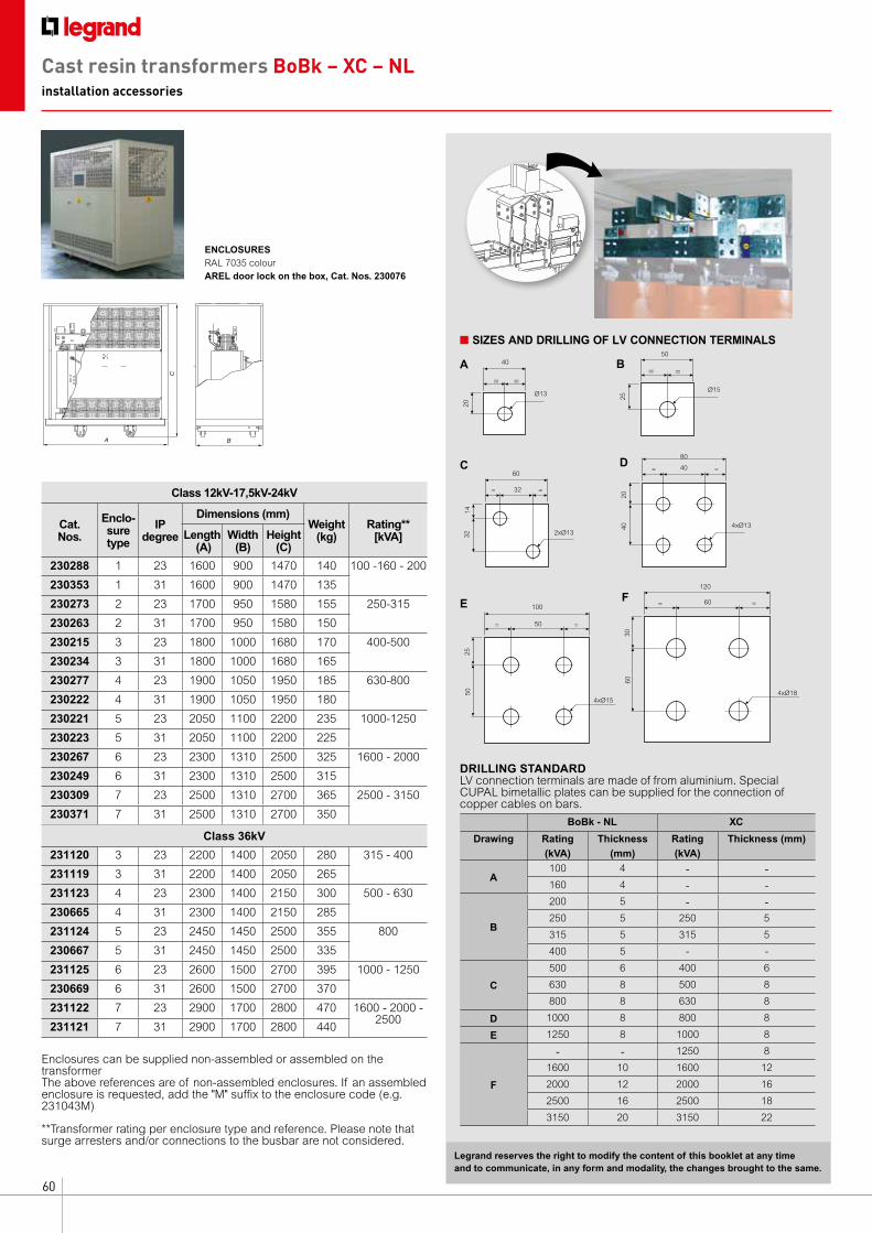
60
ENCLOSURESRAL 7035 colourAREL door lock on the box, Cat. Nos. 230076
n SIZES AND DRILLING OF LV CONNECTION TERMINALS
A
C
B
40
20
A= =
Ø13Ø15
50
25
B= =
32
32C
= =
2xØ13
1460
40
40
D= =
4xØ13
20
80
DRILLING STANDARDLV connection terminals are made of from aluminium. Special CUPAL bimetallic plates can be supplied for the connection of copper cables on bars.
BoBk - NL XC
Drawing Rating (kVA)
Thickness (mm)
Rating (kVA)
Thickness (mm)
A100 4 - -160 4 - -
B
200 5 - -250 5 250 5
315 5 315 5
400 5 - -
C
500 6 400 6
630 8 500 8
800 8 630 8
D 1000 8 800 8
E 1250 8 1000 8
F
- - 1250 8
1600 10 1600 12
2000 12 2000 16
2500 16 2500 18
3150 20 3150 22
Enclosures can be supplied non-assembled or assembled on the transformerThe above references are of non-assembled enclosures. If an assembled enclosure is requested, add the "M" suffix to the enclosure code (e.g. 231043M)
50
50
E
= =
25
10060
60
F= =
4xØ18
30
120
4xØ15
Legrand reserves the right to modify the content of this booklet at any time and to communicate, in any form and modality, the changes brought to the same.
Class 12kV-17,5kV-24kV
Cat.Nos.
Enclo-sure type
IP degree
Dimensions (mm)Weight
(kg)Rating**
[kVA]Length (A)
Width(B)
Height(C)
230288 1 23 1600 900 1470 140 100 -160 - 200
230353 1 31 1600 900 1470 135
230273 2 23 1700 950 1580 155 250-315
230263 2 31 1700 950 1580 150
230215 3 23 1800 1000 1680 170 400-500
230234 3 31 1800 1000 1680 165
230277 4 23 1900 1050 1950 185 630-800
230222 4 31 1900 1050 1950 180
230221 5 23 2050 1100 2200 235 1000-1250
230223 5 31 2050 1100 2200 225
230267 6 23 2300 1310 2500 325 1600 - 2000
230249 6 31 2300 1310 2500 315
230309 7 23 2500 1310 2700 365 2500 - 3150
230371 7 31 2500 1310 2700 350
Class 36kV
231120 3 23 2200 1400 2050 280 315 - 400
231119 3 31 2200 1400 2050 265
231123 4 23 2300 1400 2150 300 500 - 630
230665 4 31 2300 1400 2150 285
231124 5 23 2450 1450 2500 355 800
230667 5 31 2450 1450 2500 335
231125 6 23 2600 1500 2700 395 1000 - 1250
230669 6 31 2600 1500 2700 370
231122 7 23 2900 1700 2800 470 1600 - 2000 - 2500
231121 7 31 2900 1700 2800 440
**Transformer rating per enclosure type and reference. Please note that surge arresters and/or connections to the busbar are not considered.
Cast resin transformers BoBk – XC – NLinstallation accessories
61CAST RESIN TRANSFORMERS INSTALLATION AND MAINTENANCE
Installation and maintenance
• Safety guidelines
• Rating plate
• Transport, receipt and storage
• Installation
• Commissioning
• Maintenance
• Technical glossary
TABLE OF CONTENTS
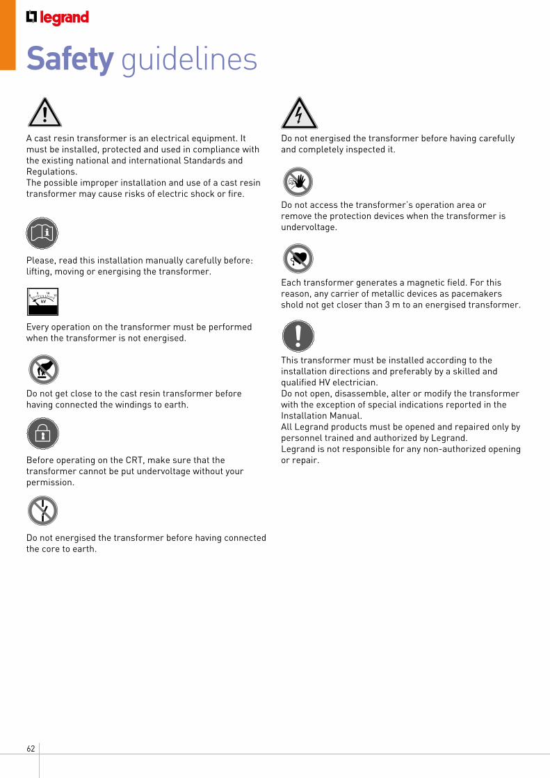
62
Safety guidelines
A cast resin transformer is an electrical equipment. It must be installed, protected and used in compliance with the existing national and international Standards and Regulations. The possible improper installation and use of a cast resin transformer may cause risks of electric shock or fire.
Please, read this installation manually carefully before: lifting, moving or energising the transformer.
Every operation on the transformer must be performed when the transformer is not energised.
Do not get close to the cast resin transformer before having connected the windings to earth.
Before operating on the CRT, make sure that the transformer cannot be put undervoltage without your permission.
Do not energised the transformer before having connected the core to earth.
05 10
15
Do not energised the transformer before having carefully and completely inspected it.
Do not access the transformer’s operation area or remove the protection devices when the transformer is undervoltage.
Each transformer generates a magnetic field. For this reason, any carrier of metallic devices as pacemakers shold not get closer than 3 m to an energised transformer.
This transformer must be installed according to the installation directions and preferably by a skilled and qualified HV electrician. Do not open, disassemble, alter or modify the transformer with the exception of special indications reported in the Installation Manual. All Legrand products must be opened and repaired only by personnel trained and authorized by Legrand. Legrand is not responsible for any non-authorized opening or repair.
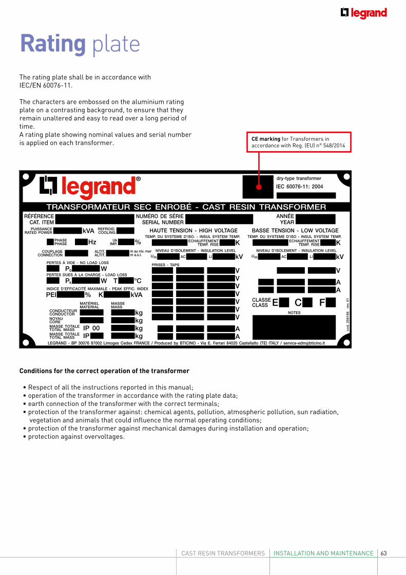
63CAST RESIN TRANSFORMERS INSTALLATION AND MAINTENANCE
Rating plate
Conditions for the correct operation of the transformer
• Respect of all the instructions reported in this manual; • operation of the transformer in accordance with the rating plate data; • earth connection of the transformer with the correct terminals; • protection of the transformer against: chemical agents, pollution, atmospheric pollution, sun radiation, vegetation and animals that could influence the normal operating conditions; • protection of the transformer against mechanical damages during installation and operation; • protection against overvoltages.
The rating plate shall be in accordance with IEC/EN 60076-11.
The characters are embossed on the aluminium rating plate on a contrasting background, to ensure that they remain unaltered and easy to read over a long period of time.A rating plate showing nominal values and serial number is applied on each transformer. CE marking for Transformers in
accordance with Reg. (EU) n° 548/2014
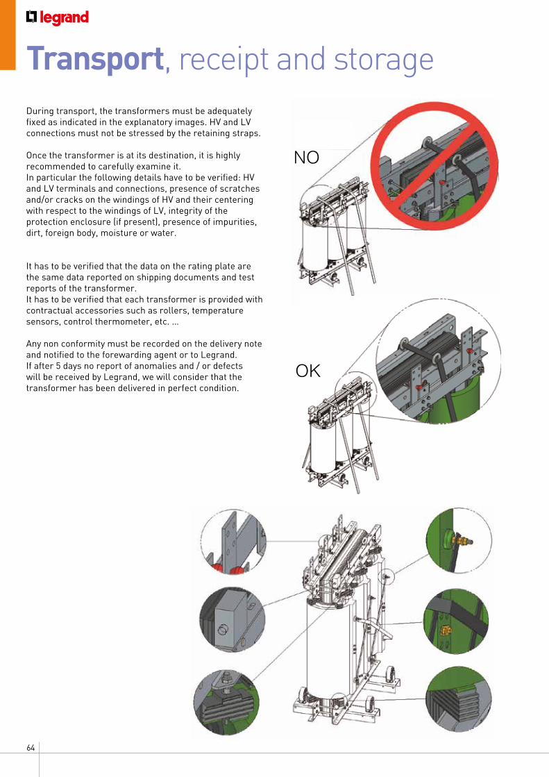
64
Transport, receipt and storageDuring transport, the transformers must be adequately fixed as indicated in the explanatory images. HV and LV connections must not be stressed by the retaining straps.
Once the transformer is at its destination, it is highly recommended to carefully examine it.In particular the following details have to be verified: HV and LV terminals and connections, presence of scratches and/or cracks on the windings of HV and their centering with respect to the windings of LV, integrity of the protection enclosure (if present), presence of impurities, dirt, foreign body, moisture or water.
It has to be verified that the data on the rating plate are the same data reported on shipping documents and test reports of the transformer.It has to be verified that each transformer is provided with contractual accessories such as rollers, temperature sensors, control thermometer, etc. …
Any non conformity must be recorded on the delivery note and notified to the forewarding agent or to Legrand.If after 5 days no report of anomalies and / or defects will be received by Legrand, we will consider that the transformer has been delivered in perfect condition.
NO
OK
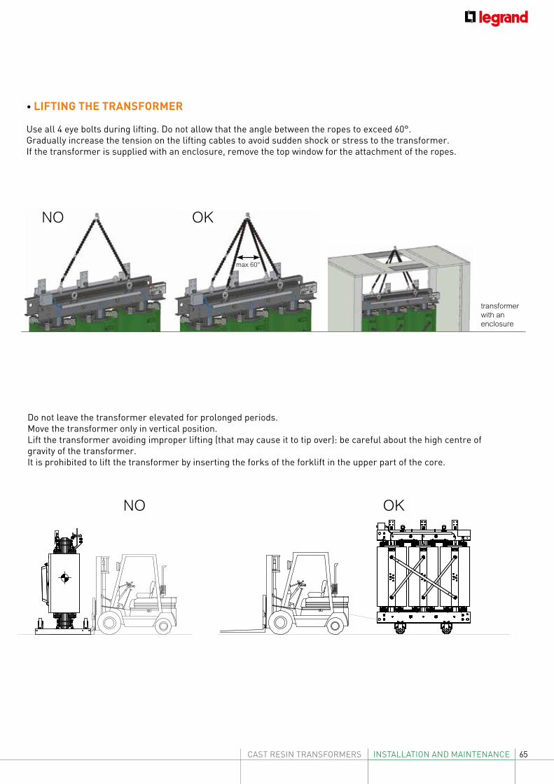
65CAST RESIN TRANSFORMERS INSTALLATION AND MAINTENANCE
max 60°
OKNO
NO OK
transformer with an enclosure
• LIFTING THE TRANSFORMER
Use all 4 eye bolts during lifting. Do not allow that the angle between the ropes to exceed 60°.Gradually increase the tension on the lifting cables to avoid sudden shock or stress to the transformer.If the transformer is supplied with an enclosure, remove the top window for the attachment of the ropes.
Do not leave the transformer elevated for prolonged periods.Move the transformer only in vertical position.Lift the transformer avoiding improper lifting (that may cause it to tip over): be careful about the high centre of gravity of the transformer.It is prohibited to lift the transformer by inserting the forks of the forklift in the upper part of the core.
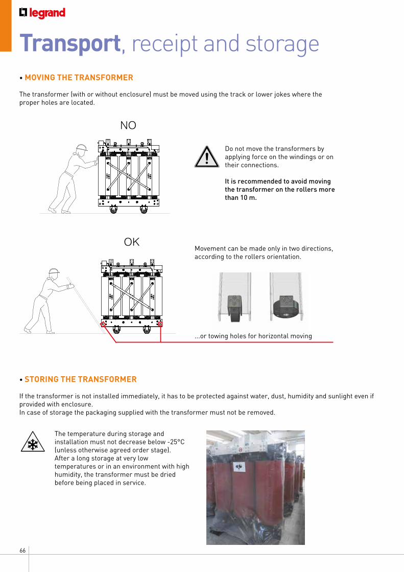
66
• MOVING THE TRANSFORMER
The transformer (with or without enclosure) must be moved using the track or lower jokes where the proper holes are located.
NO
OK
...or towing holes for horizontal moving
Do not move the transformers by applying force on the windings or on their connections.
It is recommended to avoid moving the transformer on the rollers more than 10 m.
Movement can be made only in two directions, according to the rollers orientation.
The temperature during storage and installation must not decrease below -25°C (unless otherwise agreed order stage).After a long storage at very low temperatures or in an environment with high humidity, the transformer must be dried before being placed in service.
• STORING THE TRANSFORMER
If the transformer is not installed immediately, it has to be protected against water, dust, humidity and sunlight even if provided with enclosure.In case of storage the packaging supplied with the transformer must not be removed.
Transport, receipt and storage
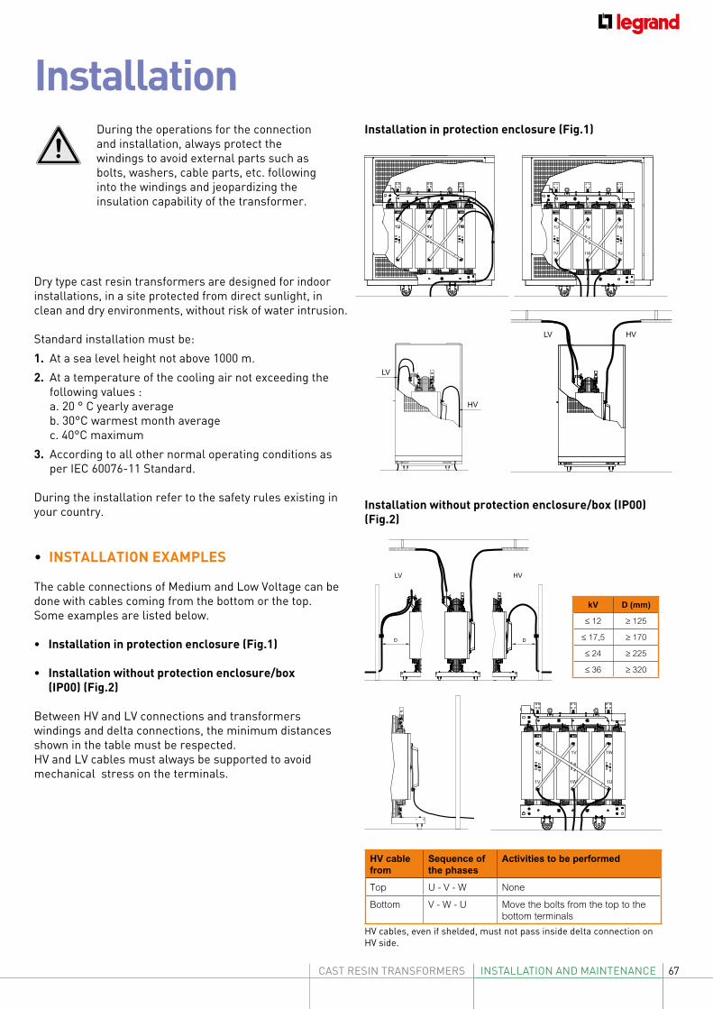
67CAST RESIN TRANSFORMERS INSTALLATION AND MAINTENANCE
Installation
Dry type cast resin transformers are designed for indoor installations, in a site protected from direct sunlight, in clean and dry environments, without risk of water intrusion.
Standard installation must be:1. At a sea level height not above 1000 m.2. At a temperature of the cooling air not exceeding the
following values : a. 20 ° C yearly average b. 30°C warmest month average c. 40°C maximum3. According to all other normal operating conditions as
per IEC 60076-11 Standard.
During the installation refer to the safety rules existing in your country.
• INSTALLATION EXAMPLES
The cable connections of Medium and Low Voltage can be done with cables coming from the bottom or the top. Some examples are listed below.
• Installation in protection enclosure (Fig.1)
• Installation without protection enclosure/box (IP00) (Fig.2)
Between HV and LV connections and transformers windings and delta connections, the minimum distances shown in the table must be respected.HV and LV cables must always be supported to avoid mechanical stress on the terminals.
1U 1V 1W 1U 1V 1W
1U1W1V
LV
HV
LV HV
Installation in protection enclosure (Fig.1)
Installation without protection enclosure/box (IP00) (Fig.2)
LV HV
DD
1U 1V 1W
1U1W1V
kV D (mm)
≤ 12 ≥ 125
≤ 17,5 ≥ 170
≤ 24 ≥ 225
≤ 36 ≥ 320
HV cable from
Sequence of the phases
Activities to be performed
Top U - V - W None
Bottom V - W - U Move the bolts from the top to the bottom terminals
HV cables, even if shelded, must not pass inside delta connection on HV side.
During the operations for the connection and installation, always protect the windings to avoid external parts such as bolts, washers, cable parts, etc. following into the windings and jeopardizing the insulation capability of the transformer.
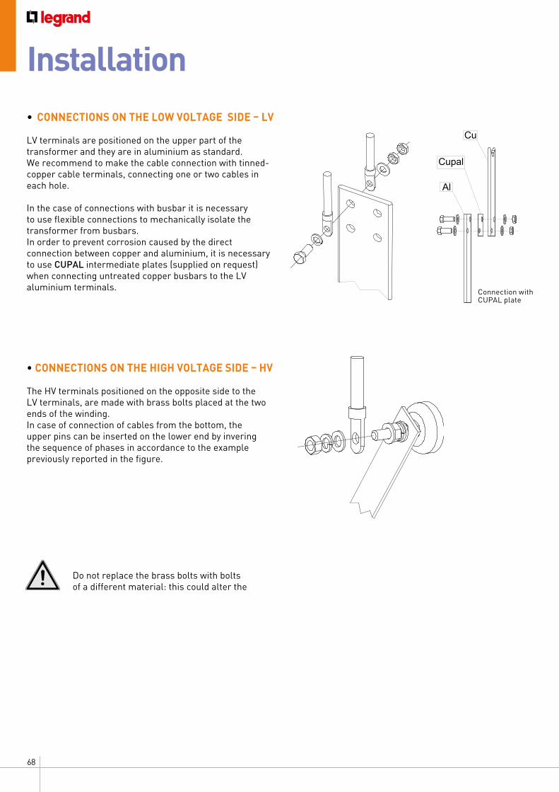
68
• CONNECTIONS ON THE LOW VOLTAGE SIDE – LV
LV terminals are positioned on the upper part of the transformer and they are in aluminium as standard.We recommend to make the cable connection with tinned-copper cable terminals, connecting one or two cables in each hole.
In the case of connections with busbar it is necessary to use flexible connections to mechanically isolate the transformer from busbars.In order to prevent corrosion caused by the direct connection between copper and aluminium, it is necessary to use CUPAL intermediate plates (supplied on request) when connecting untreated copper busbars to the LV aluminium terminals.
• CONNECTIONS ON THE HIGH VOLTAGE SIDE – HV
The HV terminals positioned on the opposite side to the LV terminals, are made with brass bolts placed at the two ends of the winding.In case of connection of cables from the bottom, the upper pins can be inserted on the lower end by invering the sequence of phases in accordance to the example previously reported in the figure.
Cu
Al
Cupal
Do not replace the brass bolts with bolts of a different material: this could alter the
Connection with CUPAL plate
Installation
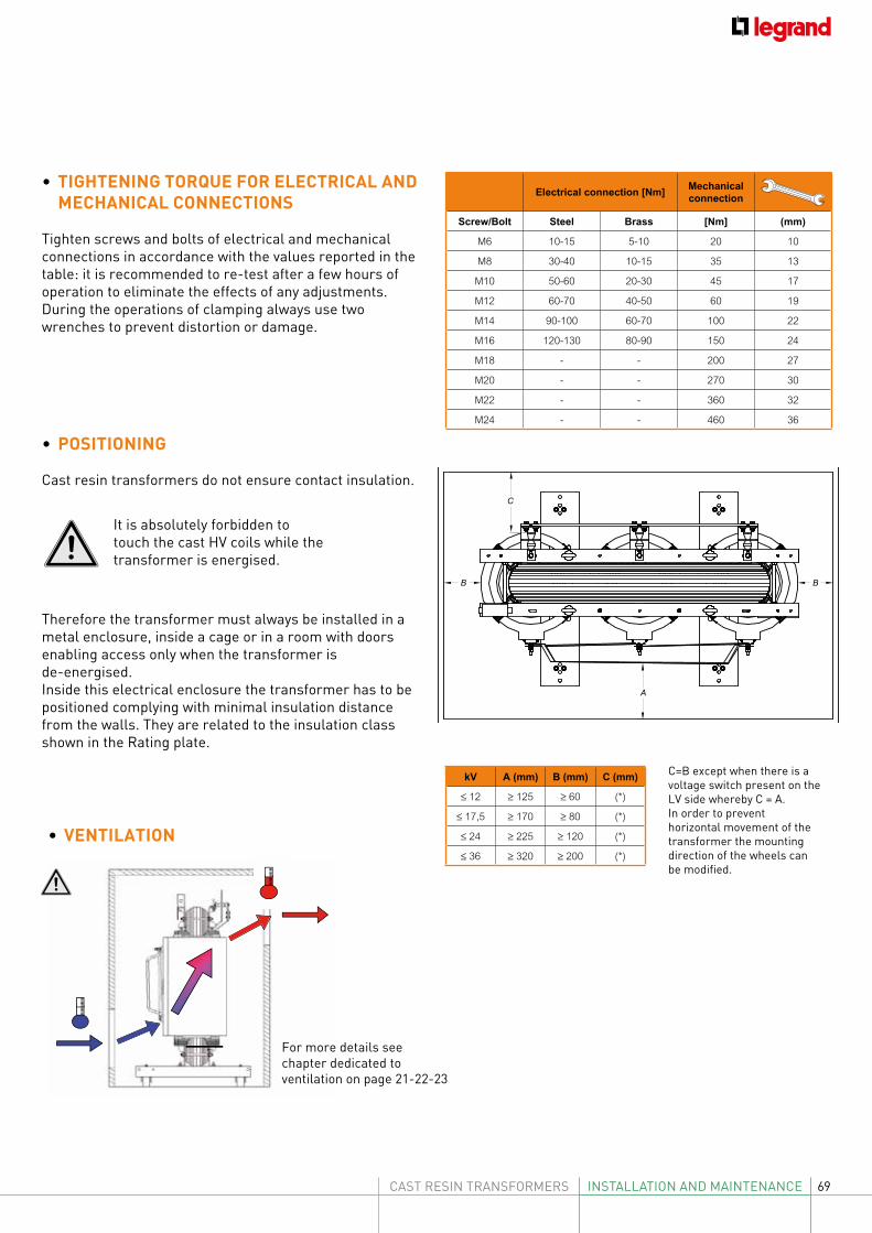
69CAST RESIN TRANSFORMERS INSTALLATION AND MAINTENANCE
Electrical connection [Nm]Mechanical connection
Screw/Bolt Steel Brass [Nm] (mm)
M6 10-15 5-10 20 10
M8 30-40 10-15 35 13
M10 50-60 20-30 45 17
M12 60-70 40-50 60 19
M14 90-100 60-70 100 22
M16 120-130 80-90 150 24
M18 - - 200 27
M20 - - 270 30
M22 - - 360 32
M24 - - 460 36
• TIGHTENING TORQUE FOR ELECTRICAL AND MECHANICAL CONNECTIONS
Tighten screws and bolts of electrical and mechanical connections in accordance with the values reported in the table: it is recommended to re-test after a few hours of operation to eliminate the effects of any adjustments.During the operations of clamping always use two wrenches to prevent distortion or damage.
C=B except when there is a voltage switch present on the LV side whereby C = A.In order to prevent horizontal movement of the transformer the mounting direction of the wheels can be modified.
BB
C
A
kV A (mm) B (mm) C (mm)
≤ 12 ≥ 125 ≥ 60 (*)
≤ 17,5 ≥ 170 ≥ 80 (*)
≤ 24 ≥ 225 ≥ 120 (*)
≤ 36 ≥ 320 ≥ 200 (*)
• POSITIONING
Cast resin transformers do not ensure contact insulation.
It is absolutely forbidden to touch the cast HV coils while the transformer is energised.
Therefore the transformer must always be installed in a metal enclosure, inside a cage or in a room with doors enabling access only when the transformer is de-energised.Inside this electrical enclosure the transformer has to be positioned complying with minimal insulation distance from the walls. They are related to the insulation class shown in the Rating plate.
pgpg
pg
• VENTILATION
For more details see chapter dedicated to ventilation on page 21-22-23
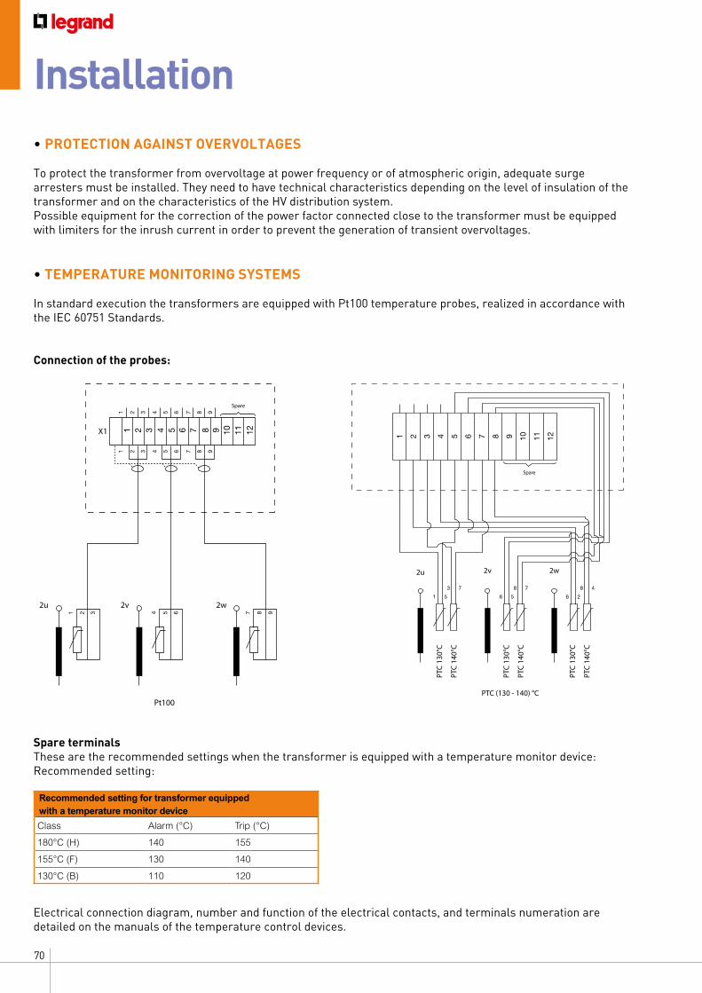
70
• PROTECTION AGAINST OVERVOLTAGES
To protect the transformer from overvoltage at power frequency or of atmospheric origin, adequate surge arresters must be installed. They need to have technical characteristics depending on the level of insulation of the transformer and on the characteristics of the HV distribution system.Possible equipment for the correction of the power factor connected close to the transformer must be equipped with limiters for the inrush current in order to prevent the generation of transient overvoltages.
• TEMPERATURE MONITORING SYSTEMS
In standard execution the transformers are equipped with Pt100 temperature probes, realized in accordance with the IEC 60751 Standards.
Connection of the probes:
Spare terminalsThese are the recommended settings when the transformer is equipped with a temperature monitor device:Recommended setting:
Electrical connection diagram, number and function of the electrical contacts, and terminals numeration are detailed on the manuals of the temperature control devices.
1 2 3 4 5 6 7 8 9 10 11 12
2u
PTC
130°
C
PTC
140°
C
PTC
130°
C
PTC
140°
C
PTC
130°
C
PTC
140°
C
2v 2w
PTC (130 - 140) °C
Spare
1 5
3 7
6 5
8 7
6 2
8 4
1
X1
Spare
2u 2v
Pt100
2w
1 2 3 4 5 6 7 8 9 10 11 12
2 3 4 5 6 7 8 9
1 2 3
1 2 3
4 5 6 7 8 9
4 5 6 7 8 9
Recommended setting for transformer equipped with a temperature monitor device
Class Alarm (°C) Trip (°C)
180°C (H) 140 155
155°C (F) 130 140
130°C (B) 110 120
Installation
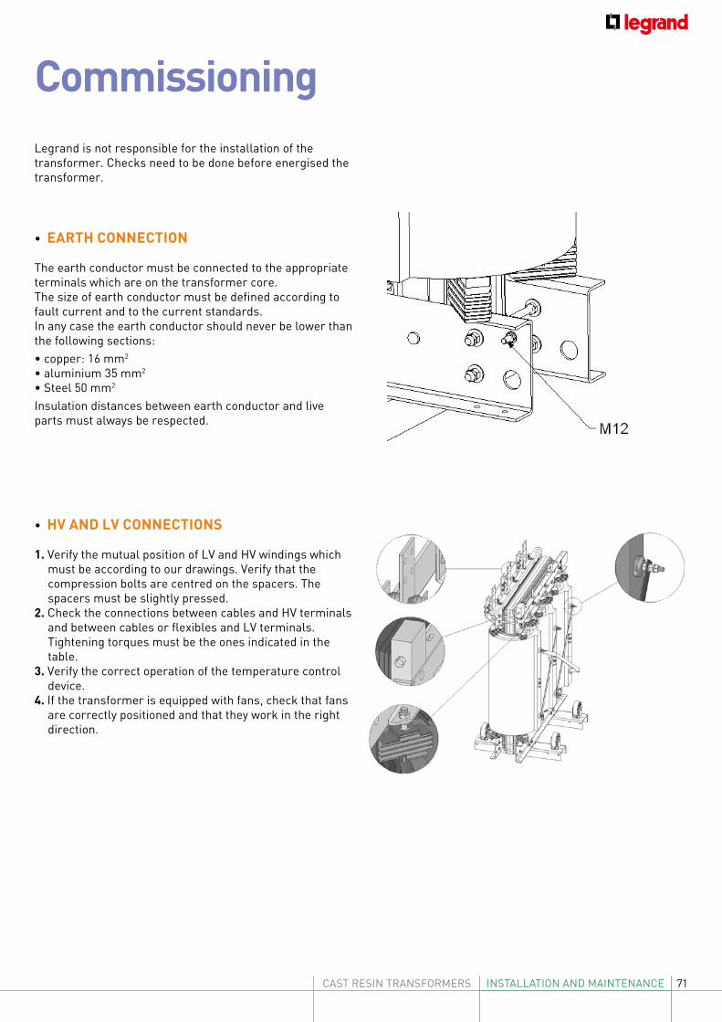
71CAST RESIN TRANSFORMERS INSTALLATION AND MAINTENANCE
CommissioningLegrand is not responsible for the installation of the transformer. Checks need to be done before energised the transformer.
• EARTH CONNECTION
The earth conductor must be connected to the appropriate terminals which are on the transformer core.The size of earth conductor must be defined according to fault current and to the current standards.In any case the earth conductor should never be lower than the following sections:• copper: 16 mm2
• aluminium 35 mm2
• Steel 50 mm2
Insulation distances between earth conductor and live parts must always be respected.
• HV AND LV CONNECTIONS
1. Verify the mutual position of LV and HV windings which must be according to our drawings. Verify that the compression bolts are centred on the spacers. The spacers must be slightly pressed.
2. Check the connections between cables and HV terminals and between cables or flexibles and LV terminals. Tightening torques must be the ones indicated in the table.
3. Verify the correct operation of the temperature control device.
4. If the transformer is equipped with fans, check that fans are correctly positioned and that they work in the right direction.
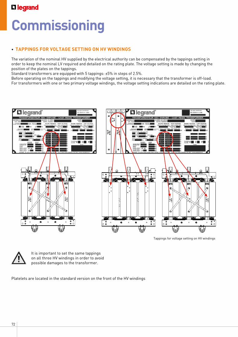
72
Tappings for voltage setting on HV windings
• TAPPINGS FOR VOLTAGE SETTING ON HV WINDINGS
The variation of the nominal HV supplied by the electrical authority can be compensated by the tappings setting inorder to keep the nominal LV required and detailed on the rating plate. The voltage setting is made by changing the position of the plates on the tappings.Standard transformers are equipped with 5 tappings: ±5% in steps of 2.5%.Before operating on the tappings and modifying the voltage setting, it is necessary that the transformer is off-load.For transformers with one or two primary voltage windings, the voltage setting indications are detailed on the rating plate.
It is important to set the same tappings on all three HV windings in order to avoid possible damages to the transformer.
Platelets are located in the standard version on the front of the HV windings
5-67-54-78-43-8
2100020500200001950019000
5-67-54-78-43-8
2100020500200001950019000
10000 20000
Commissioning
73CAST RESIN TRANSFORMERS INSTALLATION AND MAINTENANCE
• CLEANING
If the transformer has been stored for a long period, clean carefully LV and HV windings from dust, dirt and possible condensation.Clean the HV and LV windings from dust deposits, dirt and
condensation. Use a vacuum cleaner to avoid dispersion of dirt and dust
on the transformer.Make sure the room is dry, clean, with sufficient ventilation
and without the risk of ingress of water.Do not attach accessories or ducts to the windings and the
core of the transformer.
• MEASUREMENT OF WINDINGS EARTH RESISTANCE
The measurement must be performed with a Megohmmeter (Megger), working up to 5000V. HV and LV terminals must be disconnected from the electrical system, during the measurement.
The measured values should be approximately as follows:• 5000 V for 60 s: Terminals HV / LV terminals to earth ≥ 20 MΩ• 2500 V for 60 s: Terminals LV / HV terminals to earth ≥ 10 MΩ• 2500 V for 60 s: Terminals HV - LV terminals / earth ≥ 10 MΩ
If the measured values are significantly lower, dry the transformer and, if necessary, contact the after sales department.
• ENERGIZING
When the transformer is connected to the electrical system, some sparkles could be visible close to the magnetic core. This physical phenomenon does not influence the correct working of the transformer and it is not related to the quality.
If the protection systems are not correctly set, inrush current will open the circuit breaker which protects the transformer.This can generate high voltages which can damage the windings. For this reason, it is recomended to activate the second harmonic restraint.
After checking the installation and ensuring that no object/tool has been left on the transformer, it is possible to close the circuit breaker on the HV side. After energizing the transformer from the HV side, close the LV circuit breaker.
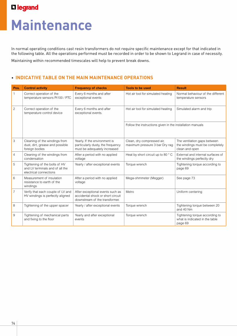
74
In normal operating conditions cast resin transformers do not require specific maintenance except for that indicated in the following table. All the operations performed must be recorded in order to be shown to Legrand in case of necessity.
Maintaining within recommended timescales will help to prevent break downs.
• INDICATIVE TABLE ON THE MAIN MAINTENANCE OPERATIONS
Pos. Control activity Frequency of checks Tools to be used Result
1 Correct operation of the temperature sensors Pt100 / PTC
Every 6 months and after exceptional events
Hot air tool for simulated heating Normal behaviour of the different temperature sensors
2 Correct operation of the temperature control device
Every 6 months and after exceptional events.
Hot air tool for simulated heating Simulated alarm and trip
Follow the instructions given in the installation manuals
3 Cleaning of the windings from dust, dirt, grease and possible foreign bodies
Yearly. If the environment is particularly dusty, the frequency must be adequately increased
Clean, dry compressed air, maximum pressure 3 bar Dry rag
The ventilation gaps between the windings must be completely clean and open
4 Cleaning of the windings from condensation
After a period with no applied voltage
Heat by short circuit up to 80 ° C External and internal surfaces of the windings perfectly dry
5 Tightening of the bolts of HV and LV terminals and of all the electrical connections
Yearly / after exceptional events Torque wrench Tightening torque according to page 69
6 Measurement of insulation resistance to earth of the windings
After a period with no applied voltage
Mega-ohmmeter (Megger) See page 73
7 Verify that each couple of LV and HV windings is perfectly aligned
After exceptional events such as accidental shock or short circuit downstream of the transformer.
Metro Uniform centering
8 Tightening of the upper spacer Yearly / after exceptional events Torque wrench Tightening torque between 20 and 40 Nm
9 Tightening of mechanical parts and fixing to the floor
Yearly and after exceptional events
Torque wrench Tightening torque according to what is indicated in the table page 69
Maintenance
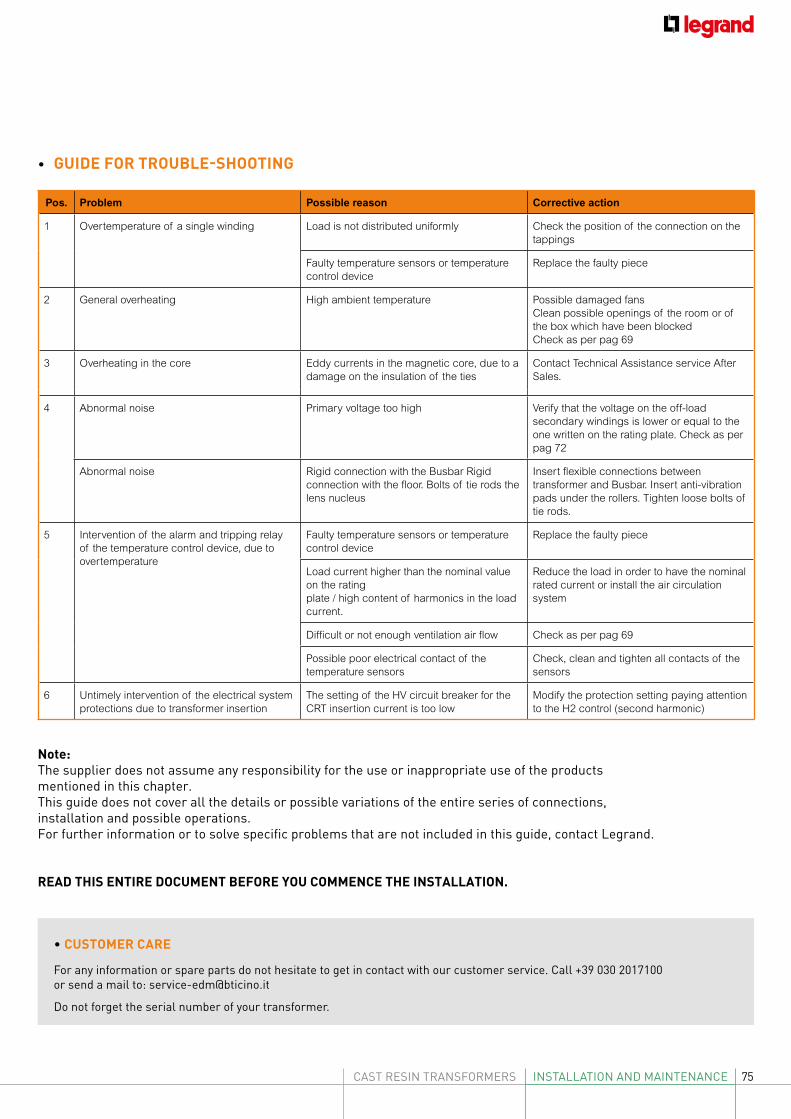
75CAST RESIN TRANSFORMERS INSTALLATION AND MAINTENANCE
• GUIDE FOR TROUBLE-SHOOTING
Pos. Problem Possible reason Corrective action
1 Overtemperature of a single winding Load is not distributed uniformly Check the position of the connection on the tappings
Faulty temperature sensors or temperature control device
Replace the faulty piece
2 General overheating High ambient temperature Possible damaged fansClean possible openings of the room or of the box which have been blockedCheck as per pag 69
3 Overheating in the core Eddy currents in the magnetic core, due to a damage on the insulation of the ties
Contact Technical Assistance service After Sales.
4 Abnormal noise Primary voltage too high Verify that the voltage on the off-load secondary windings is lower or equal to the one written on the rating plate. Check as per pag 72
Abnormal noise Rigid connection with the Busbar Rigid connection with the floor. Bolts of tie rods the lens nucleus
Insert flexible connections between transformer and Busbar. Insert anti-vibration pads under the rollers. Tighten loose bolts of tie rods.
5 Intervention of the alarm and tripping relay of the temperature control device, due to overtemperature
Faulty temperature sensors or temperature control device
Replace the faulty piece
Load current higher than the nominal value on the rating plate / high content of harmonics in the load current.
Reduce the load in order to have the nominal rated current or install the air circulation system
Difficult or not enough ventilation air flow Check as per pag 69
Possible poor electrical contact of the temperature sensors
Check, clean and tighten all contacts of the sensors
6 Untimely intervention of the electrical system protections due to transformer insertion
The setting of the HV circuit breaker for the CRT insertion current is too low
Modify the protection setting paying attention to the H2 control (second harmonic)
• CUSTOMER CARE
For any information or spare parts do not hesitate to get in contact with our customer service. Call +39 030 2017100 or send a mail to: [email protected]
Do not forget the serial number of your transformer.
Note:The supplier does not assume any responsibility for the use or inappropriate use of the products mentioned in this chapter.This guide does not cover all the details or possible variations of the entire series of connections, installation and possible operations. For further information or to solve specific problems that are not included in this guide, contact Legrand.
READ THIS ENTIRE DOCUMENT BEFORE YOU COMMENCE THE INSTALLATION.
76
Technical glossaryRated Power Sr [kVA]rated power is the conventional value of the power assigned to a winding which, together with the rated voltage, allows us to determine the rated current.
Rated voltage of a winding Ur [kV or V]voltage assigned to be applied, or developed at no-load, between the terminals of anwinding. For a three-phase winding it is the voltage between line terminals
HV (high-voltage) windingThe winding having the highest rated voltage
LV (low-voltage) windingThe winding having the lowest rated voltage
Primary windingA winding which, in service, receives active power from the supply network
Secondary windingA winding which, in service, delivers active power to the load circuit
Connection symbol a conventional notation indicating the connections of the high-voltage and low-voltage windings and their relative phase displacement expressed as a combination of letters and clock-hour figureThe star, delta, or zigzag connection of a set of phase windings of a three-phase transformer shall be indicated by the capital letters Y, D or Z for the high-voltage (HV) winding and small letters y, d or z for the low-voltage (LV) winding.Letter symbols for the different windings of a transformer are noted in descending order of rated voltage independently of the intended power flow.
Short-circuit voltage Uk(%) is the voltage to be applied between the winding line terminals so that the rated current circulates between them when the terminals of the other winding are in short-circuit. This voltage may be divided into a resistive component and an inductive component. This voltage value allows calculation of the short circuit current (Icc) at the secondary terminals if the impedance upstream is neglected, according to the formula: Icc = 100 *In/UkThe transformer impedance is also calculated with this magnitude. It is necessary to calculate this short-circuit current in the Low-Voltage distribution system according to the formula: Z =Uk % * Vn / 100*InThe transformer short-circuit currents are a function of the transformer power and are standardised on the values 4% and 6%.
No-load current (I0) is the magnetic circuit magnetisation current which is established in a winding when this is supplied at rated voltage and frequency (the other winding is open circuit). This current value is expressed in % of the transformer rated current. The magnetic circuit is made up of insulated laminations.
Inrush current (x In) is the pick-up current peak which occurs when the transformer is powered. Its initial value can be even 8 – 10 times the winding rated current. The pick-up current of a transformer must be known to determine the calibrations for the associated protection devices.
Noise [dB(A)]is caused by magnetostriction of the magnetic circuit laminations. The noise is a function of the transformer magnetic work induction and the quality of the laminations. The noise level can be expressed in terms of sound power LwA - Acoustic power [dB(A)] and is independent of the load.
No-load loss Po[W]represent the active power absorbed by the transformer when the rated voltage is applied at the rated frequency to one of the two windings and with the other winding with open circuit. No-load losses, also called iron losses, are independent of the load and are equivalent to the sum of the losses caused by the hysterisis and the eddy currents (Foucault).
Load loss Pk [W] at 120°Care instead the losses due to the ohmic currents on the main circuits, to the additional losses in the windings and to the losses on the metallic masses. These losses are proportional to the square of the load current and are expressed at a standardised reference current of 75°C for oil transformers and 120°C for cast resin transformers.
Routine testa test to which each individual transformer is subjected
Type testa test made on a transformer which is representative of other transformers, to demonstrate that these transformers comply with the specified requirements not covered by the routine tests: a transformer is considered to be representative of others if it is built to the same drawings using the same techniques and materials in the same factory
Special testa test other than a type test or a routine test, agreed by the manufacturer and the purchaser
77CAST RESIN TRANSFORMERS NOTE
NOTE

78
NOTE


AD-E
XLG
/CR
T16G
/GB
- N
ovem
ber
2016
Head officeand International Department87045 Limoges Cedex - FranceTel.: + 33 (0) 5 55 06 87 87Fax: + 33 (0) 5 55 06 74 55
FOLLOW US ALSO ON
www.legrand.com
www.youtube.com/legrand
twitter.com/@legrand