Embed Size (px)
Citation preview
Joint EUROGRAPHICS - IEEE TCVG Symposium on Visualization (2004)O. Deussen, C. Hansen, D.A. Keim, D. Saupe (Editors)
Case Study: Visual Analysis of Complex, Time-DependentSimulation Results of a Diesel Exhaust System
Helmut Doleisch1, Michael Mayer1, Martin Gasser1, Roland Wanker2, Helwig Hauser1
1 VRVis Research Center, Vienna, Austria, {Doleisch,Mayer,Gasser,Hauser}@VRVis.at http://www.VRVis.at/vis/2 AVL List GmbH, Graz, Austria, [email protected], http://www.avl.com/
AbstractIn previous work we have presented visualization techniques that provide engineers with a high degree of inter-activity and flexibility for analyzing large, time-dependent, and high-dimensional data sets resulting from CFD(computational fluid dynamics) simulations. In this case study we apply our techniques in the fields of the automo-tive engineering industry and demonstrate how users benefit from using them during their routine analysis, as wellas for exploring new phenomena. For coping with some of the special requirements in this application, we adaptedand extended parts of the system. A comparison of two related cases of a diesel exhaust system is presented, andsome important questions about these cases are addressed.
1. Introduction
The analysis of data which results from computational sim-ulation is challenging and complex, but also important tospeed up simulation-cycles, which leads to shortening de-sign and development times of new products. One interest-ing application field for computational simulations is in sim-ulating catalyst processes in a diesel exhaust system in theautomotive industry.
Data resulting from CFD (computational fluid dynam-ics) simulations has a few special properties, including,for example, large amounts of data or complex geometri-cal models used for the simulations. The large amounts ofdata (typically in the range of billions of data values foreach simulation cycle) result mainly from three differentsources: detailed geometrical models (in terms of numbersof cells), time-dependency and multi-dimensionality (manyattributes) for each cell of the model. Complex geometricalmodels as employed, e.g. in simulating diesel exhaust sys-tems, pose problems in understanding relationships betweendifferent data items, if not presented in a visual form.
In this paper we present a case study, showing howvisualization effectively helps to analyze complex, multi-dimensional, and time-dependent simulation results. Forthese types of applications, suitable visualization tools mustfulfill certain requirements. One key requirement is interac-tivity, i.e., allowing the user to change visualization parame-ters interactively and interact with parts of the data. Then,providing high flexibility for exploring multi-dimensionaldata, allowing complex specifications of what parts of the
data are of current interest, is also crucial for the users. Fi-nally, users know their data very well, thus successful visual-ization tools must enable the users to access their data usinga data-based approach.
When visualizing and analyzing large, 3D, and time-dependent data resulting from flow simulation, often (semi-)automatic feature extraction methods are used, as discussedin an overview by Post et al. [10]. Besides these feature ex-traction methods, only a small amount of work on interac-tive feature specification has been presented so far. Henzedeveloped a technique to visualize and analyze time-varyingCFD data by using multiple, linked views in a system calledLinked Derived Spaces [8]. Gresh et al. presented a systemcalled WEAVE [7], which combines information visualiza-tion (InfoVis) and 3D scientific visualization (SciVis) and al-lows investigations in the 3D context based on marking dataaccording to different attributes.
In previous work [4, 5] we have developed visualizationtechniques, that focus on fulfilling the requirements dis-cussed above, in a system called SimVis (see also section 3).We have shown that combining methods from SciVis and In-foVis provides powerful possibilities for visualizing multi-dimensional simulation results computed on 3D grids. Incontrast to our system, common commercial systems forpost processing and visualization of simulation results usu-ally provide only views of 2D slices or surfaces and verylimited interaction possibilities. Three different types oftools are mainly used: planar cuts, views of surfaces or iso-surfaces onto which specific attributes are color-mapped.
c The Eurographics Association 2004.
Doleisch, Mayer, Gasser, Wanker, Hauser / Case Study: Visual Analysis of a Diesel Exhaust System
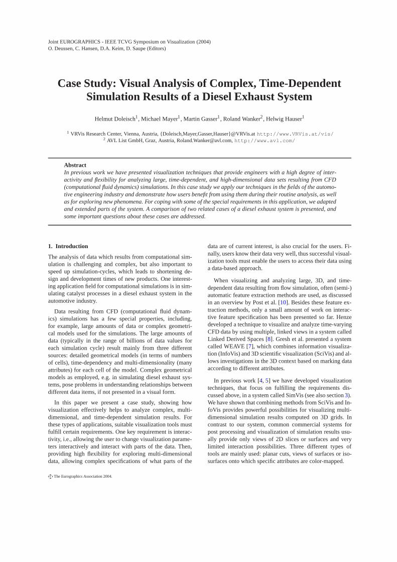
Figure 1: A diesel exhaust system consisting of a diesel oxi-dation catalyst (DOC) and a diesel particulate filter (DPF).
In this paper, we present a recent case study that we car-ried out at the VRVis Research Center together with our part-ner AVL List. We use SimVis to demonstrate how the use ofInfoVis and SciVis views can extend and improve the resultsof analysis of CFD data.
2. Application Scenario
The application presented in this case study is a diesel ex-haust system for passenger cars powered by diesel engines.We first shortly describe such a diesel exhaust system, andafterwards discuss several important questions of engineerswho work on the development of such a system.
2.1. Diesel Exhaust System
For passenger cars powered by diesel engines, layout anddesign of the diesel oxidation catalysts (DOC), used to re-duce hydrocarbons and CO emissions, are standard appli-cations. Because of decreasing legal limits for particulates,diesel particular filters (DPF) are in the focus of recent re-search [9]. In this case study a diesel exhaust system (see fig-ure 1), consisting of a diesel oxidation catalyst and a dieselparticulate filter, is analyzed.
The DOC is still the only catalyst technology that demon-strates the required robustness and durability and has beencommercially established in a number of light- and heavy-duty applications. At sufficiently high exhaust temperatures,diesel oxidation catalysts can provide very effective controlof hydrocarbons and CO emissions, with reduction efficien-cies in the order of 90%.
The DPF traps the diesel particulates (soot) of the exhaustgas in its filter material. Over time the collected particulatesblock the filter which would negatively affect the engine op-eration. Therefore, diesel filter systems have to provide away of removing particulates from the filter periodically torestore its soot collection capacity (filter regeneration). Thisis attained by oxidizing the collected particulates at hightemperatures to gaseous products, primarily CO2. To achievethis high temperature in the DPF, the engine operates on richconditions, which means that there is more fuel injected thannecessary for a complete combustion. Due to the incompletecombustion, the amount of CO and hydrocarbons increasesin the exhaust gas, which oxidize in the DOC and therebyheat the gas. This raises the temperature of the DPF itselfand the oxidation of the particulates starts.
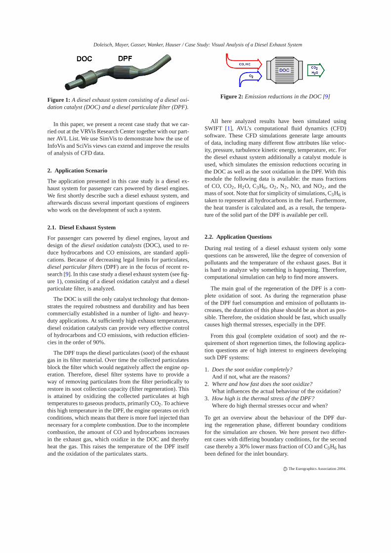
Figure 2: Emission reductions in the DOC [9]
All here analyzed results have been simulated usingSWIFT [1], AVL’s computational fluid dynamics (CFD)software. These CFD simulations generate large amountsof data, including many different flow attributes like veloc-ity, pressure, turbulence kinetic energy, temperature, etc. Forthe diesel exhaust system additionally a catalyst module isused, which simulates the emission reductions occuring inthe DOC as well as the soot oxidation in the DPF. With thismodule the following data is available: the mass fractionsof CO, CO2, H2O, C3H6, O2, N2, NO, and NO2, and themass of soot. Note that for simplicity of simulations, C3H6 istaken to represent all hydrocarbons in the fuel. Furthermore,the heat transfer is calculated and, as a result, the tempera-ture of the solid part of the DPF is available per cell.
2.2. Application Questions
During real testing of a diesel exhaust system only somequestions can be answered, like the degree of conversion ofpollutants and the temperature of the exhaust gases. But itis hard to analyze why something is happening. Therefore,computational simulation can help to find more answers.
The main goal of the regeneration of the DPF is a com-plete oxidation of soot. As during the regeneration phaseof the DPF fuel consumption and emission of pollutants in-creases, the duration of this phase should be as short as pos-sible. Therefore, the oxidation should be fast, which usuallycauses high thermal stresses, especially in the DPF.
From this goal (complete oxidation of soot) and the re-quirement of short regenertion times, the following applica-tion questions are of high interest to engineers developingsuch DPF systems:
1. Does the soot oxidize completely?And if not, what are the reasons?
2. Where and how fast does the soot oxidize?What influences the actual behaviour of the oxidation?
3. How high is the thermal stress of the DPF?Where do high thermal stresses occur and when?
To get an overview about the behaviour of the DPF dur-ing the regeneration phase, different boundary conditionsfor the simulation are chosen. We here present two differ-ent cases with differing boundary conditions, for the secondcase thereby a 30% lower mass fraction of CO and C3H6 hasbeen defined for the inlet boundary.
c The Eurographics Association 2004.
Doleisch, Mayer, Gasser, Wanker, Hauser / Case Study: Visual Analysis of a Diesel Exhaust System
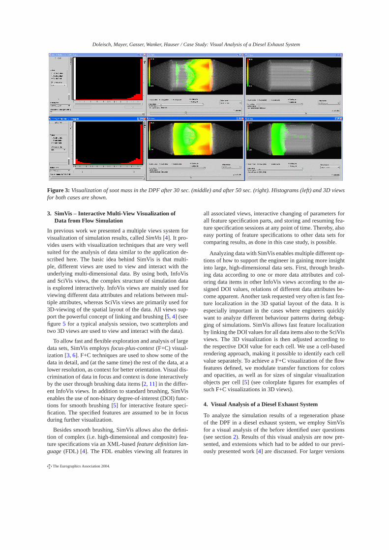
Figure 3: Visualization of soot mass in the DPF after 30 sec. (middle) and after 50 sec. (right). Histograms (left) and 3D viewsfor both cases are shown.
3. SimVis – Interactive Multi-View Visualization ofData from Flow Simulation
In previous work we presented a multiple views system forvisualization of simulation results, called SimVis [4]. It pro-vides users with visualization techniques that are very wellsuited for the analysis of data similar to the application de-scribed here. The basic idea behind SimVis is that multi-ple, different views are used to view and interact with theunderlying multi-dimensional data. By using both, InfoVisand SciVis views, the complex structure of simulation datais explored interactively. InfoVis views are mainly used forviewing different data attributes and relations between mul-tiple attributes, whereas SciVis views are primarily used for3D-viewing of the spatial layout of the data. All views sup-port the powerful concept of linking and brushing [5, 4] (seefigure 5 for a typical analysis session, two scatterplots andtwo 3D views are used to view and interact with the data).
To allow fast and flexible exploration and analysis of largedata sets, SimVis employs focus-plus-context (F+C) visual-ization [3, 6]. F+C techniques are used to show some of thedata in detail, and (at the same time) the rest of the data, at alower resolution, as context for better orientation. Visual dis-crimination of data in focus and context is done interactivelyby the user through brushing data items [2, 11] in the differ-ent InfoVis views. In addition to standard brushing, SimVisenables the use of non-binary degree-of-interest (DOI) func-tions for smooth brushing [5] for interactive feature speci-fication. The specified features are assumed to be in focusduring further visualization.
Besides smooth brushing, SimVis allows also the defini-tion of complex (i.e. high-dimensional and composite) fea-ture specifications via an XML-based feature definition lan-guage (FDL) [4]. The FDL enables viewing all features in
all associated views, interactive changing of parameters forall feature specification parts, and storing and resuming fea-ture specification sessions at any point of time. Thereby, alsoeasy porting of feature specifications to other data sets forcomparing results, as done in this case study, is possible.
Analyzing data with SimVis enables multiple different op-tions of how to support the engineer in gaining more insightinto large, high-dimensional data sets. First, through brush-ing data according to one or more data attributes and col-oring data items in other InfoVis views according to the as-signed DOI values, relations of different data attributes be-come apparent. Another task requested very often is fast fea-ture localization in the 3D spatial layout of the data. It isespecially important in the cases where engineers quicklywant to analyze different behaviour patterns during debug-ging of simulations. SimVis allows fast feature localizationby linking the DOI values for all data items also to the SciVisviews. The 3D visualization is then adjusted according tothe respective DOI value for each cell. We use a cell-basedrendering approach, making it possible to identify each cellvalue separately. To achieve a F+C visualization of the flowfeatures defined, we modulate transfer functions for colorsand opacities, as well as for sizes of singular visualizationobjects per cell [5] (see colorplate figures for examples ofsuch F+C visualizations in 3D views).
4. Visual Analysis of a Diesel Exhaust System
To analyze the simulation results of a regeneration phaseof the DPF in a diesel exhaust system, we employ SimVisfor a visual analysis of the before identified user questions(see section 2). Results of this visual analysis are now pre-sented, and extensions which had to be added to our previ-ously presented work [4] are discussed. For larger versions
c The Eurographics Association 2004.
Doleisch, Mayer, Gasser, Wanker, Hauser / Case Study: Visual Analysis of a Diesel Exhaust System
of the images as presented here, as well as for some more re-sults and additional animation sequences, and a longer ver-sion of this case study as technical report, please refer tohttp://www.VRVis.at/vis/research/diesel-case/.
One general extension to our previous work was the ex-tension to handle time-dependent data, both for visualizationand also for feature specification. Each view can either showdata of one timestep, or accumulate the data of many succes-sive timesteps (building a so-called timeslab). Another ex-tension was added to the F+C idea. When visualizing time-dependent data, two levels of context can be distinguished: a2nd level context representing data of all timesteps which arecurrently not active, and the standard F+C discrimination forall data in the currently active timesteps of the chosen times-lab. The data items belonging to the 2nd level context are vi-sualized additionally using a less prominant representation,e.g. grey-colored points in a scatterplot (see figure 4).
4.1. Does the soot oxidize completely?
Complete soot oxidation is the main goal of the simulation ofthe DPF regeneration phase. In the case of incomplete sootoxidation, analysis of sources for this behaviour are of high-est interest. To analyze the soot oxidation process, first sootmass values are investigated. Therefore, in two histograms,the soot mass values are displayed for all timesteps of bothcases. A brush is applied in the upper histogram view (seefigure 3), selecting all data items of case one having a sootmass value greater than 0 (selected data is colored red inSimVis InfoVis views). Note that we always show the viewsfor the first simulation case (with more CO and C3H6 at theinlet) above the views of the second case for comparison ofresults throughout this section. To ensure correct comparisonand analysis of the results of both cases, all feature specifica-tions performed in the first case are saved and loaded againfor the second case (using the FDL of SimVis), thus the sameparameters for the brushes are guaranteed. In figure 3 twodifferent timesteps are shown in the 3D views in the middleand right, where soot mass values are color-mapped in thefocus parts of the above described brushed regions.
As clearly seen, in the first case there is almost no sootleft after 50 seconds, but in the second case the soot does notoxidize completely, there are still fractions of the soot in thefront part of the DPF after 50 seconds. To explore the reasonfor that, the temperature values in the DPF are investigated,as shown in Colorplate 1, left side, for 20 seconds after thesimulation start. It can be seen that the temperature in thefirst case is much higher than in the second one. The reasonfor that is, that more hydrocarbons and CO oxidize in theDOC in the first case due to higher C3H6 and CO mass frac-tion at the inlet. The oxidation generates more heat, whichresults in a higher fluid temperature, heating the DPF andthe oxidation of soot starts quicker. As a result the effective-ness of the soot oxidation increases in the rear, and the sootoxidizes completely in this region, too. To sum up the first
question, a high mass fraction of C3H6 and CO is needed fora complete soot oxidation.
4.2. Where and how fast does the soot oxidize?
For this question only the second case is of interest becauseof the incomplete soot oxidation. Due to soot oxidation, CO2and CO are generated in regions of high temperature. To dis-play these areas, it is necessary to specify a complex fea-ture. In a first scatterplot the mass fraction of CO2 (Y-axis)is plotted against the mass fraction of CO (X-axis). A smoothbrush selecting higher values of both attributes is applied(see Colorplate 1, right, upper scatterplot view). Then, in asecond step, to refine the first 2D brush, a second scatterplotshowing general fluid temperature (Y-axis) vs. the spatial X-coordinates of the data set (X-axis) is used. Note that thespatial X-axis of this data set correlates very well with themain flow direction through the whole data set (from left toright in figure 1). Here, high values of fluid temperature inthe region of the DPF are brushed, leading to a 3D, com-posite brush. The two scatterplots as well as a 3D view areshown in Colorplate 1 on the right. In the 3D view, velocityvalues are color mapped. Visualization shows, that the COand the CO2 production are not symmetric.
For a better understanding, the oxidation progress has tobe analyzed. This can be done by displaying only cells witha high mass soot gradient. As the amplitude of the gradi-ent values changes over time, we need a method to selectrelativly high gradient values with respect to the maximumgradient value for each timestep, to get interesting cells foreach timestep separately. Therefore differences of the sootmass values over time are calculated and normalized. Withnormalized differences we can easily select the upper 20%of difference values per timestep, for example. And here an-other extension of SimVis was added. We included a dataderivation tool, where derived data (time-dependent) can becalculated. Standard derived data calculation in SimVis in-cludes calculation of differences over time (central, forwardor backward differences), smoothing of data over time, cal-culation of spatial regions exhibiting low change rates, etc.After such a derived data calculation, all of these deriveddata attributes can be accessed and used for visualization andanalysis in any of the views of the system. We also includeda tool for local (with respect to time) normalization of dataattributes to cope with changing attribute value ranges.
After calculating the differences of the soot mass valuesand normalizing them, a scatterplot showing the normalizedmass soot gradients (X-axis) and the mass soot gradients (Y-axis) is used. Low mass soot gradients and low normalizedmass soot gradients are brushed in this scatterplot (see Col-orplate 2, upper left). Note that central differences are usedfor the approximation of gradients, which in the case of masssoot oxidation are negative, thus the lower gradient valuesare selected. For better illustration and better exploration asecond scatterplot showing the mass soot gradients (Y-axis)and the time domain (X-axis) is also shown below. Here the
c The Eurographics Association 2004.
Doleisch, Mayer, Gasser, Wanker, Hauser / Case Study: Visual Analysis of a Diesel Exhaust System
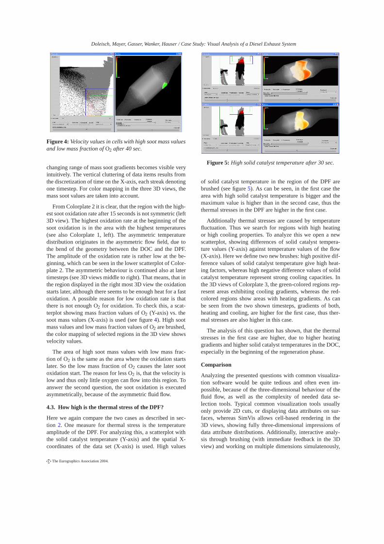
Figure 4: Velocity values in cells with high soot mass valuesand low mass fraction of O2 after 40 sec.
changing range of mass soot gradients becomes visible veryintuitively. The vertical cluttering of data items results fromthe discretization of time on the X-axis, each streak denotingone timestep. For color mapping in the three 3D views, themass soot values are taken into account.
From Colorplate 2 it is clear, that the region with the high-est soot oxidation rate after 15 seconds is not symmetric (left3D view). The highest oxidation rate at the beginning of thesoot oxidation is in the area with the highest temperatures(see also Colorplate 1, left). The asymmetric temperaturedistribution originates in the asymmetric flow field, due tothe bend of the geometry between the DOC and the DPF.The amplitude of the oxidation rate is rather low at the be-ginning, which can be seen in the lower scatterplot of Color-plate 2. The asymmetric behaviour is continued also at latertimesteps (see 3D views middle to right). That means, that inthe region displayed in the right most 3D view the oxidationstarts later, although there seems to be enough heat for a fastoxidation. A possible reason for low oxidation rate is thatthere is not enough O2 for oxidation. To check this, a scat-terplot showing mass fraction values of O2 (Y-axis) vs. thesoot mass values (X-axis) is used (see figure 4). High sootmass values and low mass fraction values of O2 are brushed,the color mapping of selected regions in the 3D view showsvelocity values.
The area of high soot mass values with low mass frac-tion of O2 is the same as the area where the oxidation startslater. So the low mass fraction of O2 causes the later sootoxidation start. The reason for less O2 is, that the velocity islow and thus only little oxygen can flow into this region. Toanswer the second question, the soot oxidation is executedasymmetrically, because of the asymmetric fluid flow.
4.3. How high is the thermal stress of the DPF?
Here we again compare the two cases as described in sec-tion 2. One measure for thermal stress is the temperatureamplitude of the DPF. For analyzing this, a scatterplot withthe solid catalyst temperature (Y-axis) and the spatial X-coordinates of the data set (X-axis) is used. High values
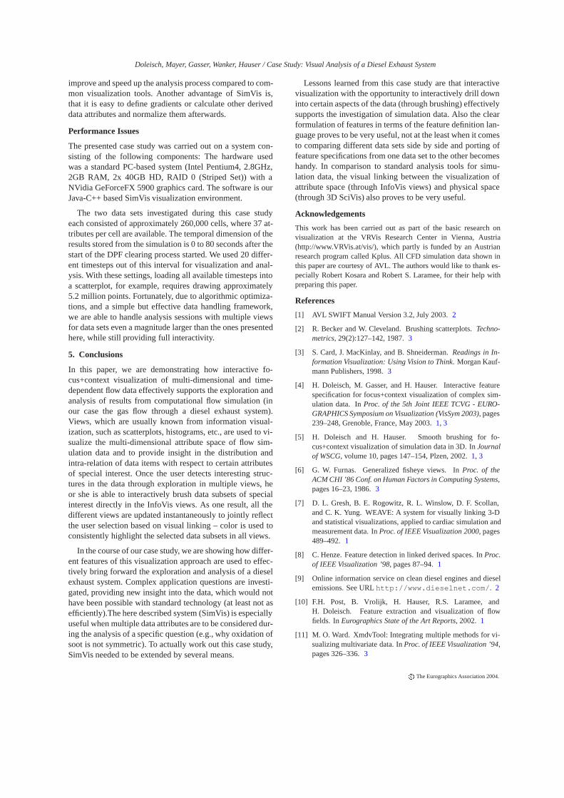
Figure 5: High solid catalyst temperature after 30 sec.
of solid catalyst temperature in the region of the DPF arebrushed (see figure 5). As can be seen, in the first case thearea with high solid catalyst temperature is bigger and themaximum value is higher than in the second case, thus thethermal stresses in the DPF are higher in the first case.
Additionally thermal stresses are caused by temperaturefluctuation. Thus we search for regions with high heatingor high cooling properties. To analyze this we open a newscatterplot, showing differences of solid catalyst tempera-ture values (Y-axis) against temperature values of the flow(X-axis). Here we define two new brushes: high positive dif-ference values of solid catalyst temperature give high heat-ing factors, whereas high negative difference values of solidcatalyst temperature represent strong cooling capacities. Inthe 3D views of Colorplate 3, the green-colored regions rep-resent areas exhibiting cooling gradients, whereas the red-colored regions show areas with heating gradients. As canbe seen from the two shown timesteps, gradients of both,heating and cooling, are higher for the first case, thus ther-mal stresses are also higher in this case.
The analysis of this question has shown, that the thermalstresses in the first case are higher, due to higher heatinggradients and higher solid catalyst temperatures in the DOC,especially in the beginning of the regeneration phase.
Comparison
Analyzing the presented questions with common visualiza-tion software would be quite tedious and often even im-possible, because of the three-dimensional behaviour of thefluid flow, as well as the complexity of needed data se-lection tools. Typical common visualization tools usuallyonly provide 2D cuts, or displaying data attributes on sur-faces, whereas SimVis allows cell-based rendering in the3D views, showing fully three-dimensional impressions ofdata attribute distributions. Additionally, interactive analy-sis through brushing (with immediate feedback in the 3Dview) and working on multiple dimensions simulatenously,
c The Eurographics Association 2004.
Doleisch, Mayer, Gasser, Wanker, Hauser / Case Study: Visual Analysis of a Diesel Exhaust System
improve and speed up the analysis process compared to com-mon visualization tools. Another advantage of SimVis is,that it is easy to define gradients or calculate other deriveddata attributes and normalize them afterwards.
Performance Issues
The presented case study was carried out on a system con-sisting of the following components: The hardware usedwas a standard PC-based system (Intel Pentium4, 2.8GHz,2GB RAM, 2x 40GB HD, RAID 0 (Striped Set)) with aNVidia GeForceFX 5900 graphics card. The software is ourJava-C++ based SimVis visualization environment.
The two data sets investigated during this case studyeach consisted of approximately 260,000 cells, where 37 at-tributes per cell are available. The temporal dimension of theresults stored from the simulation is 0 to 80 seconds after thestart of the DPF clearing process started. We used 20 differ-ent timesteps out of this interval for visualization and anal-ysis. With these settings, loading all available timesteps intoa scatterplot, for example, requires drawing approximately5.2 million points. Fortunately, due to algorithmic optimiza-tions, and a simple but effective data handling framework,we are able to handle analysis sessions with multiple viewsfor data sets even a magnitude larger than the ones presentedhere, while still providing full interactivity.
5. Conclusions
In this paper, we are demonstrating how interactive fo-cus+context visualization of multi-dimensional and time-dependent flow data effectively supports the exploration andanalysis of results from computational flow simulation (inour case the gas flow through a diesel exhaust system).Views, which are usually known from information visual-ization, such as scatterplots, histograms, etc., are used to vi-sualize the multi-dimensional attribute space of flow sim-ulation data and to provide insight in the distribution andintra-relation of data items with respect to certain attributesof special interest. Once the user detects interesting struc-tures in the data through exploration in multiple views, heor she is able to interactively brush data subsets of specialinterest directly in the InfoVis views. As one result, all thedifferent views are updated instantaneously to jointly reflectthe user selection based on visual linking – color is used toconsistently highlight the selected data subsets in all views.
In the course of our case study, we are showing how differ-ent features of this visualization approach are used to effec-tively bring forward the exploration and analysis of a dieselexhaust system. Complex application questions are investi-gated, providing new insight into the data, which would nothave been possible with standard technology (at least not asefficiently).The here described system (SimVis) is especiallyuseful when multiple data attributes are to be considered dur-ing the analysis of a specific question (e.g., why oxidation ofsoot is not symmetric). To actually work out this case study,SimVis needed to be extended by several means.
Lessons learned from this case study are that interactivevisualization with the opportunity to interactively drill downinto certain aspects of the data (through brushing) effectivelysupports the investigation of simulation data. Also the clearformulation of features in terms of the feature definition lan-guage proves to be very useful, not at the least when it comesto comparing different data sets side by side and porting offeature specifications from one data set to the other becomeshandy. In comparison to standard analysis tools for simu-lation data, the visual linking between the visualization ofattribute space (through InfoVis views) and physical space(through 3D SciVis) also proves to be very useful.
Acknowledgements
This work has been carried out as part of the basic research onvisualization at the VRVis Research Center in Vienna, Austria(http://www.VRVis.at/vis/), which partly is funded by an Austrianresearch program called Kplus. All CFD simulation data shown inthis paper are courtesy of AVL. The authors would like to thank es-pecially Robert Kosara and Robert S. Laramee, for their help withpreparing this paper.
References
[1] AVL SWIFT Manual Version 3.2, July 2003. 2
[2] R. Becker and W. Cleveland. Brushing scatterplots. Techno-metrics, 29(2):127–142, 1987. 3
[3] S. Card, J. MacKinlay, and B. Shneiderman. Readings in In-formation Visualization: Using Vision to Think. Morgan Kauf-mann Publishers, 1998. 3
[4] H. Doleisch, M. Gasser, and H. Hauser. Interactive featurespecification for focus+context visualization of complex sim-ulation data. In Proc. of the 5th Joint IEEE TCVG - EURO-GRAPHICS Symposium on Visualization (VisSym 2003), pages239–248, Grenoble, France, May 2003. 1, 3
[5] H. Doleisch and H. Hauser. Smooth brushing for fo-cus+context visualization of simulation data in 3D. In Journalof WSCG, volume 10, pages 147–154, Plzen, 2002. 1, 3
[6] G. W. Furnas. Generalized fisheye views. In Proc. of theACM CHI ’86 Conf. on Human Factors in Computing Systems,pages 16–23, 1986. 3
[7] D. L. Gresh, B. E. Rogowitz, R. L. Winslow, D. F. Scollan,and C. K. Yung. WEAVE: A system for visually linking 3-Dand statistical visualizations, applied to cardiac simulation andmeasurement data. In Proc. of IEEE Visualization 2000, pages489–492. 1
[8] C. Henze. Feature detection in linked derived spaces. In Proc.of IEEE Visualization ’98, pages 87–94. 1
[9] Online information service on clean diesel engines and dieselemissions. See URL http://www.dieselnet.com/. 2
[10] F.H. Post, B. Vrolijk, H. Hauser, R.S. Laramee, andH. Doleisch. Feature extraction and visualization of flowfields. In Eurographics State of the Art Reports, 2002. 1
[11] M. O. Ward. XmdvTool: Integrating multiple methods for vi-sualizing multivariate data. In Proc. of IEEE Visualization ’94,pages 326–336. 3
c The Eurographics Association 2004.
Doleisch, Mayer, Gasser, Wanker, Hauser / Case Study: Visual Analysis of a Diesel Exhaust System
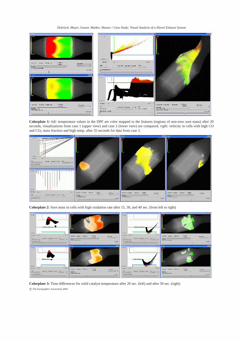
Colorplate 1: left: temperature values in the DPF are color mapped to the features (regions of non-zero soot mass) after 20seconds, visualizations from case 1 (upper view) and case 2 (lower view) are compared; right: velocity in cells with high COand CO2 mass fraction and high temp. after 35 seconds for data from case 2.
Colorplate 2: Soot mass in cells with high oxidation rate after 15, 30, and 40 sec. (from left to right)
Colorplate 3: Time differences for solid catalyst temperature after 20 sec. (left) and after 50 sec. (right)c The Eurographics Association 2004.
![Computational Photography - TU Wien · 7 Beautification [Deussen et al.] DataData--Driven Enhancement Driven Enhancement of Facial Attractiveness Tommer Leyvand, Daniel Cohen-Or,](https://img.pdfslide.us/doc/110x75/5b80fcee7f8b9aeb088e75cc/computational-photography-tu-wien-7-beautification-deussen-et-al-datadata-driven.jpg)