Embed Size (px)
Citation preview

FO
RM
AP
PR
OV
ED
�
O
MB
CO
NT
RO
L N
O. 2
040
- 021
3
�
EX
PIR
AT
ION
DA
TE: 1
2/31
/02
Case Study Short Questionnaire
January 2000
U.S. Environmental Protection Agency (EPA)Office of Wastewater ManagementWashington, DC
Notice of Estimated Burden
EPA estimates that completion of the entire Case Study Short Questionnaire will require an averageof 10 hours per facility. This estimate includes time for reading the instructions and reviewing theinformation necessary to respond to the questionnaire form. Any comments regarding EPA’s needfor the information, the accuracy of the provided burden estimate, and suggested methods forreducing respondent burden (including the use of automated collection techniques) should beaddressed to: Director, Regulatory Information Division, Office of Policy, Mail Code 2137, U.S.EPA, 401 M Street, SW, Washington, DC 20460. Please include the OMB Control Number, listedin the left-hand margin on this page, with any correspondence.


Certification Statement
Case Study Short Questionnaire
Certification Statement
Instructions
The individual responsible for directing or supervising the preparation of the enclosed Case Study ShortQuestionnaire must read and sign the Certification Statement below before returning both documents to the U.S.Environmental Protection Agency. The certifying official must be a responsible corporate official or his (or her)duly authorized representative. The Certification Statement must be completed and submitted in accordance withthe requirements contained in the Code of Federal Regulations at 40 CFR 122.22.
I certify under penalty of law that the attached questionnaire was prepared under mydirection or supervision in accordance with a system designed to ensure that qualifiedpersonnel properly gathered and evaluated the information submitted. The informationsubmitted is, to the best of my knowledge and belief, accurate and complete. In those caseswhere we did not possess the requested information, we have provided best engineeringestimates or judgments. We have, to the best of our ability, indicated what we believe to becompany confidential business information as defined under 40 CFR Part 2, Subpart B. Weunderstand that we may be required at a later time to justify our claim in detail with respectto each item claimed confidential. I am aware that there are significant penalties forsubmitting false information, including the possibility of fines and imprisonment as explainedin Section 308 of the Clean Water Act (33 U.S.C., Section 1318).
Signature of Certifying Official Date
( )
Printed Name of Certifying Official Telephone No.
Title of Certifying Official

Case Study Short Questionnaire
THIS PAGE INTENTIONALLY LEFT BLANK
Table of Contents
Case Study Short Questionnaire i
Table of Contents
Certification Statement
General Information and Instructions . . . . . . . . . . . . . . . . . . . . . . . . . . . . . . . . . . . . . . . . . . . . . . . . . . . . . . . . iii
Section 1: General Facility Information . . . . . . . . . . . . . . . . . . . . . . . . . . . . . . . . . . . . . . . . . . . . . . . . . . . . . . 1
Section 2: General Scoping Data . . . . . . . . . . . . . . . . . . . . . . . . . . . . . . . . . . . . . . . . . . . . . . . . . . . . . . . . . . 3
Section 3: Design and Operational Data for Cooling Water Intake Structuresand Cooling Water Systems . . . . . . . . . . . . . . . . . . . . . . . . . . . . . . . . . . . . . . . . . . . . . . . . . . . . . 5
Section 4: Facility and Firm-Level Economic Data . . . . . . . . . . . . . . . . . . . . . . . . . . . . . . . . . . . . . . . . . . . . 15
Section 5: Facility Production and Electricity Generation Data . . . . . . . . . . . . . . . . . . . . . . . . . . . . . . . . . . . 19
Glossary . . . . . . . . . . . . . . . . . . . . . . . . . . . . . . . . . . . . . . . . . . . . . . . . . . . . . . . . . . . . . . . . . . . . . . . . . . . . G-1

ii Case Study Short Questionnaire
THIS PAGE INTENTIONALLY LEFT BLANK

General Information and Instructions
Case Study Short Questionnaire iii
General Information and Instructions
Why This Questionnaire?
The U.S. Environmental Protection Agency (EPA) is currently developing regulations under Section 316(b)of the Clean Water Act, 33 U.S.C., Section 1326(b). Section 316(b) provides that any standard establishedpursuant to Sections 301 or 306 of the Clean Water Act (CWA) and applicable to a point source willrequire that the location, design, construction, and capacity of cooling water intake structures reflect thebest technology available (BTA) for minimizing adverse environmental impact.
In support of the Section 316(b) regulations, EPA will conduct a series of case studies. This questionnairetargets facilities located in particular areas that have been chosen as case study sites. The questionnaireis intended to capture facility-specific information needed to conduct the case studies. The Section 316(b)case studies will be used to do one or more of the following: (1) characterize the baseline, especially withrespect to Section 316(b) technologies in place; (2) provide a very detailed and in-depth analysis of thepotential costs and benefits of Section 316(b) regulations for specific regions of concern; (3) helpdemonstrate the site-specific nature of environmental impacts of CWIS and potential benefits ofimplementing BTA; (4) support the development of a tiering framework for the Section 316(b) regulation;(5) evaluate cumulative impact potential; (6) determine the effectiveness of specific technologies; (7)produce models of national benefits; and (8) provide examples of how a permit writer would analyze aplant when issuing a permit. The actual use of the questionnaire data is likely to differ for different casestudy locations.
Please note that the data from this questionnaire will not be used to make BTA permitting decisions forindividual facilities. The questionnaires are tools for characterizing some of the following: type and natureof facilities using cooling water, specific uses of cooling water, design and configuration of cooling watersystems and cooling water intake structures, types of technologies being used at intake structures, andwhether facilities have previously evaluated the environmental impacts of their cooling water intakestructures. Data from the questionnaires will be factored into other research being conducted by EPA thatis more specifically designed to determine the nature of adverse impacts and the types of controltechnologies that might minimize such impacts. All of EPA’s research efforts will feed the developmentof regulatory options, some of which will subsequently be fashioned into a proposed rulemaking that willbe put forth for public review and comment.
The enclosed case study questionnaire consists of five main sections. Section 1 requests general facilityinformation, such as facility name, location, and Standard Industrial Classification (SIC) codes. Section 2requests information from facilities on such topics as National Pollutant Discharge Elimination System(NPDES) permit status, whether cooling water is used and, if so, whether it is withdrawn by the facilityfrom surface water. Finally, information is requested on the types of activities for which the facility usescooling water directly withdrawn from surface water. The purpose of these two sections is to help EPAdetermine the nature of facilities within an industry group that use cooling water. Additionally, theinformation will help EPA identify (i.e., “screen”) facilities that are not subject to Section 316(b). Theseout-of-scope facilities will be exempted from completing the remaining sections of this questionnaire andwill be excluded from the pool of facilities chosen to receive a more detailed case study questionnaire.
General Information and Instructions
iv Case Study Short Questionnaire
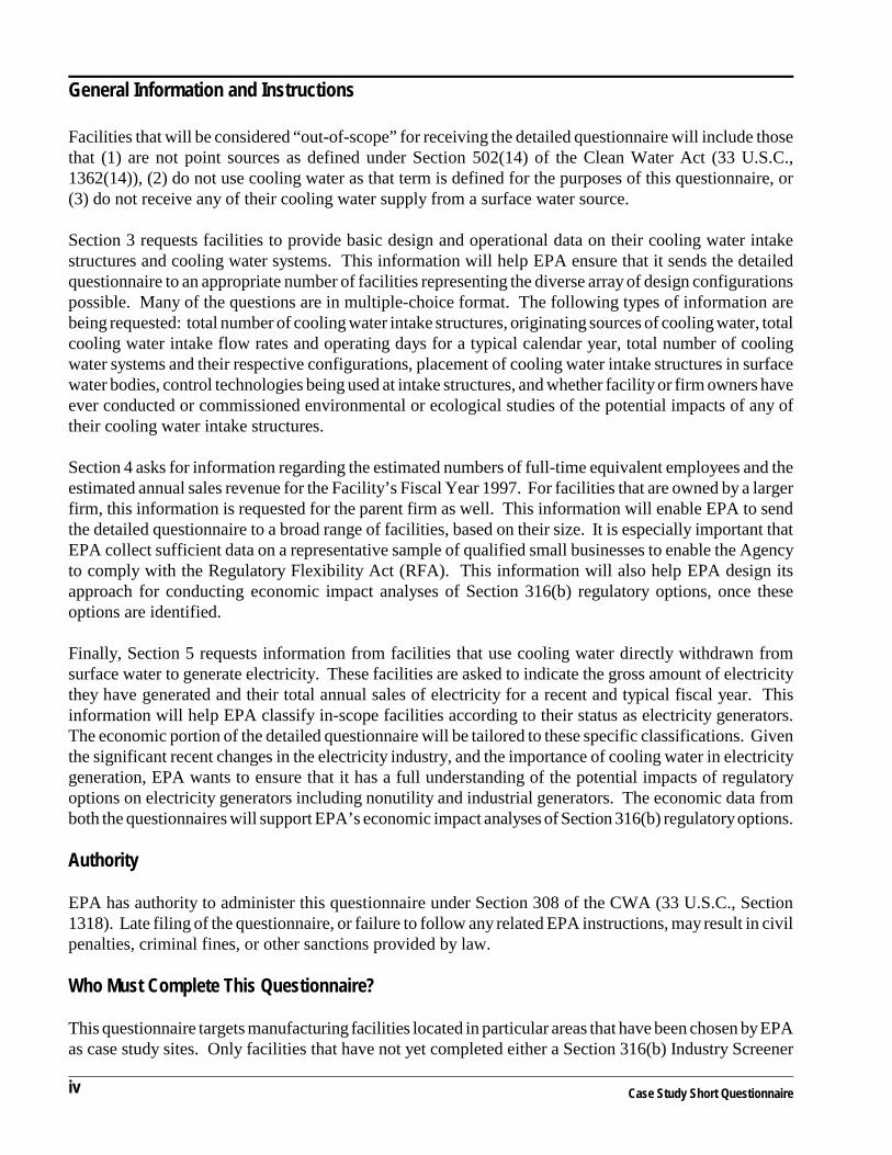
Facilities that will be considered “out-of-scope” for receiving the detailed questionnaire will include thosethat (1) are not point sources as defined under Section 502(14) of the Clean Water Act (33 U.S.C.,1362(14)), (2) do not use cooling water as that term is defined for the purposes of this questionnaire, or(3) do not receive any of their cooling water supply from a surface water source.
Section 3 requests facilities to provide basic design and operational data on their cooling water intakestructures and cooling water systems. This information will help EPA ensure that it sends the detailedquestionnaire to an appropriate number of facilities representing the diverse array of design configurationspossible. Many of the questions are in multiple-choice format. The following types of information arebeing requested: total number of cooling water intake structures, originating sources of cooling water, totalcooling water intake flow rates and operating days for a typical calendar year, total number of coolingwater systems and their respective configurations, placement of cooling water intake structures in surfacewater bodies, control technologies being used at intake structures, and whether facility or firm owners haveever conducted or commissioned environmental or ecological studies of the potential impacts of any oftheir cooling water intake structures.
Section 4 asks for information regarding the estimated numbers of full-time equivalent employees and theestimated annual sales revenue for the Facility’s Fiscal Year 1997. For facilities that are owned by a largerfirm, this information is requested for the parent firm as well. This information will enable EPA to sendthe detailed questionnaire to a broad range of facilities, based on their size. It is especially important thatEPA collect sufficient data on a representative sample of qualified small businesses to enable the Agencyto comply with the Regulatory Flexibility Act (RFA). This information will also help EPA design itsapproach for conducting economic impact analyses of Section 316(b) regulatory options, once theseoptions are identified.
Finally, Section 5 requests information from facilities that use cooling water directly withdrawn fromsurface water to generate electricity. These facilities are asked to indicate the gross amount of electricitythey have generated and their total annual sales of electricity for a recent and typical fiscal year. Thisinformation will help EPA classify in-scope facilities according to their status as electricity generators.The economic portion of the detailed questionnaire will be tailored to these specific classifications. Giventhe significant recent changes in the electricity industry, and the importance of cooling water in electricitygeneration, EPA wants to ensure that it has a full understanding of the potential impacts of regulatoryoptions on electricity generators including nonutility and industrial generators. The economic data fromboth the questionnaires will support EPA’s economic impact analyses of Section 316(b) regulatory options.
Authority
EPA has authority to administer this questionnaire under Section 308 of the CWA (33 U.S.C., Section1318). Late filing of the questionnaire, or failure to follow any related EPA instructions, may result in civilpenalties, criminal fines, or other sanctions provided by law.
Who Must Complete This Questionnaire?
This questionnaire targets manufacturing facilities located in particular areas that have been chosen by EPAas case study sites. Only facilities that have not yet completed either a Section 316(b) Industry Screener

General Information and Instructions
Case Study Short Questionnaire v
� Toll-Free Help LineCase Study Short Questionnaire
Science Applications International Corporation (SAIC)Available weekdays, 9:00 a.m. to 5:00 p.m., Eastern Time
Toll-Free Phone No.: 1-800-246-3113 Direct Dial Phone No.: (703) 318-4676 (long distance charges will apply)
� Case Study Short Questionnaire
316(b) SurveyU.S. Environmental Protection Agency c/o SAIC (R-1-3)11251 Roger Bacon DriveReston, VA 20190-5201
Questionnaire or a Section 316(b) Detailed Questionnaire will be required to complete this questionnaire.The questionnaire targets facilities in industries that have been identified as using large quantities ofcooling water. These industries include the following four major industrial categories: Paper and AlliedProducts (SIC 26), Chemical and Allied Products (SIC 28), Petroleum and Coal Products (SIC 29), andPrimary Metals (SIC 33).
Where to Get Help?
Certification Statement
A responsible corporate official or his or her duly authorized representative must verify the accuracy ofthe facility’s responses to the questionnaire by reading and signing the enclosed Certification Statement.This statement needs to be returned to EPA along with the completed questionnaire.
When and How to Return the Questionnaire?
You must complete and return the Case Study Short Questionnaire and Certification Statement to EPAwithin 45 calendar days after receiving the materials at your facility or firm. Please return your materials,in the enclosed self-addressed envelope, to:
NOTE: Please keep a copy of the completed questionnaire and Certification Statement for your records.
If you have extenuating circumstances that preclude you from meeting the 45 day deadline, please contactDeborah Nagle at the following e-mail address: [email protected] to discuss your situation.

General Information and Instructions
vi Case Study Short Questionnaire
Confidential Business Information
You may assert a business confidentiality claim for some or all of your responses to the short technicalquestionnaire, as described in 40 CFR 2.203(b) (see full text below). Complete regulations governingconfidentiality of business information (CBI) appear in 40 CFR, Part 2, Subpart B.
40 CFR 2.203(b) Method and time of asserting business confidentiality claim. A business which is submittinginformation to EPA may assert a business confidentiality claim covering the information by placing on (or attachingto) the information, at the time it is submitted to EPA, a cover sheet, stamped or typed legend, or other suitable formof notice employing language such as ‘trade secret,’ ‘proprietary,’ or ‘company confidential.’ Allegedly confidentialportions of otherwise nonconfidential documents should be clearly identified by the business, and may be submittedseparately to facilitate identification and handling by EPA. If the business desires confidential treatment only untila certain date or until the occurrence of a certain event, the notice should so state.
You may claim confidentiality of business information for any of your responses by checking (�) thecircle to the left of certain questions or by one of the methods described above. Alternatively, all eligiblequestions in this questionnaire may be globally claimed confidential by checking the circle at the end ofthis paragraph. Note, however, that certain types of information cannot be considered confidential underthe CWA (e.g., plant location, water body, water body type, intake flow data). Questions that cannot beclaimed as confidential do not have CBI check-off circles. If no check mark appears on this page or in thecheck-off circles on other pages and no other claim of confidentiality has been made with respect to anyof your given responses, EPA may make the data available to the public without further notice. Please notethat you may be required to justify any claim of confidentiality at a later time.
All eligible data are CBI �
If EPA reveals information covered by a claim of confidentiality, the Agency will strictly follow therequirements and procedures set forth in 40 CFR Part 2, Subpart B. Overall, EPA may reveal submittedinformation protected by a CBI claim only to other employees, officers, or authorized representatives ofthe United States who are responsible for implementation of the Clean Water Act. EPA has extensivestandard operating procedures in place to handle, store, and transmit CBI data and has a long history ofsuccessfully managing this type of information. In addition, personnel expected to handle CBI data arerequired by the Agency to be trained and certified.
Agency contractors will have access to CBI data so that work can be performed under their contractsrelative to the Section 316(b) rulemaking. All EPA contracts require that contractor employees must useCBI data only to perform work specified by EPA. The information is not to be shown to anyone, otherthan EPA officials, without prior written approval having been received from the affected business or fromEPA’s legal office.

Section
Cooling Water Intake Structure Technology Information C
Case Study Short Questionnaire vii
Specific Instructions for Completing the Questionnaire
Facility or firm personnel most knowledgeable of the subject areas covered by thequestions posed should complete the questionnaire:
• Please answer the questions in sequence unless you are directed to SKIPforward in the questionnaire. This is important since many questions are onlyapplicable to some respondents.
• Clearly mark responses to all questions with a black or blue ink pen, or typeresponses in the spaces provided.
• For each question, please read all instructions and definitions carefully.
• Most key terms are defined at the point where they first appear in the questionnaire.They are also defined in the Glossary, which is attached to the back of thequestionnaire. Before responding to a given question, please read thedefinitions of any key terms used and any question-specific instructions.
• Please use the units specified when responding to questions requestingmeasurement data (e.g., gallons per day).
• Please provide responses on the basis of the time period(s) cited in eachquestion. Note that the time periods under which information is requested variesfrom question to question.
• Please indicate whether information provided in any of your responses isconfidential. Such information will be protected under EPA’s confidentialityprocedures. To claim a particular response as containing confidential businessinformation, simply check (�) the circle found at the bottom of the page for theapplicable question, if one is provided, or follow the other identification proceduresdescribed on the previous page and found under 40 CFR 2.203(b).

Part 2. Technical Data
viii Case Study Short Questionnaire
THIS PAGE INTENTIONALLY LEFT BLANK
Section
General Facility Information 1
Case Study Short Questionnaire 1
�Yes (1) SKIP TO Q.2
�No (2)
Section 1: General Facility Information
1. (a) Does the above mailing label reflect the facility’s full legalname and address?
(b) Please provide the complete legal name and mailing addressfor the facility:
Name of Facility: (1)
Street Address: (2)
P.O. Box (if applicable): (3)
City, State ZIP: (4)
Telephone Number: ( ) (5)
DUNS Number: __ __ – __ __ __ – __ __ __ __ (6)
[� Check (�) here if none.]

Section
1 General Facility Information
2 Case Study Short Questionnaire
�Yes (1)
�No (2) STOPIf answer is No, pleasestop here and returnquestionnaire with acompleted CertificationStatement.
2. Please identify the person responsible for questionnaireresponses, and please provide the appropriate title and contactinformation:
NOTE: The facility contact person provided here should be the person mostknowledgeable about the information provided in this survey. This personis not required to be the certifying official.
Name: (1)
Title: (2)
Employer (full legal name): (3)
Relationship to Facility (e.g., domestic parentfirm, contractor, etc.): (4)
Telephone No: ( )_____________ (5a) Fax No: ( ) (5b)
Best Time to Contact: (6)
3. Is the facility presently in commercial service?
NOTE: To clarify for plants who are not in a commercial business,interpret this question as “Is your plant currently operating?”
4. What are the four-digit Standard Industrial Classification(SIC) codes associated with the facility’s main lines of business?[Please use the SIC codes contained in the Office of Management and Budget’s1987 Standard Industrial Classification Manual. This listing can also be found atthe following Internet site: www.osha.gov/cgi-bin/sic/sicser5.]
NOTE: Since the 1930s, SIC codes have been used to facilitate thecollection, tabulation, presentation, and analysis of data relating to U.S.business establishments by Federal statistical agencies (e.g., Office ofManagement and Budget or OMB, Bureau of the Census, etc.). The systemwas last updated by OMB in 1987. It was recently replaced by the NorthAmerican Industry Classification System (NAICS) in 1997; however, itcontinues to be used by many Federal agencies. EPA believes it would beunnecessarily confusing to ask facilities to classify themselves using NAICScodes for the purposes of this questionnaire.
Primary __ __ __ __(1)
Secondary __ __ __ __(2)
Other __ __ __ __(3a) __ __ __ __(3b) __ __ __ __(3c)

Section
General Scoping Data 2
Case Study Short Questionnaire 3
�Yes (1)
�No (2) STOPIf answer is No, pleasestop here and returnquestionnaire with acompleted CertificationStatement.
�Yes (1)
�No (2) STOPIf answer is No, pleasestop here and returnquestionnaire with acompleted CertificationStatement.
DEFINITION For the purposes of this questionnaire, the term “coolingwater” refers to both contact and noncontact cooling
water, including water used for air conditioning, equipment cooling,evaporative cooling tower makeup, and dilution of effluent heat content.The intended use of the cooling water is to absorb waste heat rejected fromthe process or processes employed or from auxiliary operations on thefacility’s premises.
�Yes (1)
�No (2) STOPIf answer is No, pleasestop here and returnquestionnaire with acompleted CertificationStatement.DEFINITIONS For the purposes of this questionnaire, surface water
includes lakes, ponds, or reservoirs; nontidal rivers orstreams; tidal rivers; estuaries; fjords; oceans; and bays/coves. A coolingwater intake structure is the total structure and associated technologiesused to direct water from a water body into a facility up to the point of thefirst intake pump or series of pumps. The intended use of the cooling wateris to absorb waste heat rejected from processes employed or from auxiliaryoperations on the facility’s premises. Single cooling water intake structuresmight have multiple intake bays. If a facility has an intake structure thatwithdraws water for other purposes in addition to cooling, the entire intakestructure should be considered a cooling water intake structure for thepurposes of this questionnaire.
Section 2: General Scoping Data
5. Does the facility presently have or is the facility presently in theprocess of obtaining a National Pollutant DischargeElimination System (NPDES) permit?
NOTE: NPDES permits are required to be held under Section 402 of theClean Water Act (33 U.S.C. 1342 et seq.) by any point source thatdischarges pollutants directly to waters of the United States. Facilities thatdischarge 100 percent of their effluent (including storm water) to publicly-owned treatment works, privately-owned treatment works, and/or to groundwater injection wells should answer “No” to this question.
6. Since January 1, 1996, has cooling water been used for contactor noncontact cooling purposes at the facility? [Please consider allcooling water used regardless of the type of water source or provider from whichit has been obtained.]
7. Since January 1, 1996, has the facility directly obtained anyportion of its cooling water from a surface water source?
NOTE: In order for a facility to directly withdraw cooling water fromsurface water, it must have an intake structure.

Section
2 General Scoping Data
4 Case Study Short Questionnaire
8. In the matrix below, please indicate the activities for which your facility has used cooling waterdirectly withdrawn from surface water since January 1, 1996? [Please check (����) all applicable activities.]
Activities Requiring Cooling Water Directly Withdrawn by Facility From Surface WaterSince January 1, 1996
ItemNo. Activities
8(a) Electricity Generation (including equipment cooling) . . . . . . . . . . . . . . . . . . . . . . . . . . . . . . . . . . . . . . . . . . . . . . . . �(1)
[� Check (�) here if any of facility’s generating units that use cooling water are part of a combined cycle unit.]
Definition: For the purposes of this questionnaire, a combined cycle unit is an electric generating unit that has oneor more gas turbines or internal combustion engines and one or more steam boilers. Part of the required input to theboiler(s) is provided by the exhaust gas (waste heat) of the combustion turbines(s).
8(b) Air Conditioning (Cooling and Heating of Indoor Air) . . . . . . . . . . . . . . . . . . . . . . . . . . . . . . . . . . . . . . . . . . . . . . �(2)
Definition: For the purposes of this questionnaire, air conditioning refers to the process and equipment used tocontrol the temperature and humidity of indoor air. Cooling water is used in some types of air conditioning systems.
8(c) Production Line (or Process) Contact or Noncontact Cooling . . . . . . . . . . . . . . . . . . . . . . . . . . . . . . . . . . . . . . . �(3)
(for uses other than electricity generation and excluding air conditioning)
Definition: For the purposes of this questionnaire, the term production line refers to each of the successive stepstaken at a facility to produce a product, except the production line’s use of electricity.
8(d) Other (please describe below): . . . . . . . . . . . . . . . . . . . . . . . . . . . . . . . . . . . . . . . . . . . . . . . . . . . . . . . . . . . . . . . . . . �(4)

Section
Design and Operational Data 3
Case Study Short Questionnaire 5
___________
Section 3: Design and Operational Data for Cooling Water Intake Structuresand Cooling Water Systems
9. How many intake structures does the facility have that directly withdraw surface water to support, atleast in part, contact or noncontact cooling operations within the facility? [Consider only those intakestructures presently operating or temporarily offline (i.e., expected to operate again in the future). Do not include intake
structures planned or under construction or permanently offline.] . . . . . . . . . . . . . . . . . . . . . . . .
10. For each intake structure reported under Q.9, please indicate in the matrix below all surface watersources from which the facility has directly withdrawn contact or noncontact cooling water sinceJanuary 1, 1996 (or from the date the intake structure became operational if that date was later thanJanuary 1, 1996). [Please check (����) all water sources that apply per intake structure. If cooling water has been withdrawnfrom an intake canal/channel or constructed intake embayment/bay/cove, please indicate the originating source(s) of the water.]
Matrix 10 Matrix ___ of ___
Originating Surface Water Sources of Cooling Water Since January 1, 1996by Cooling Water Intake Structure (CWIS)Response space has been provided for two CWISs. If your facility has more than this number of intake structures, please copy the matrix and changethe CWIS code names or numbers as appropriate. Insert any additional matrices into this section of the questionnaire, and identify individual matrixsheets as Matrix “1 of 3,” “2 of 3,” etc.
WaterSourceCode
Originating Surface Water Source[Please check (����) all sources that apply per CWIS.]
Note: If cooling water has been withdrawn froman intake canal/channel or constructed intake embayment/bay/cove,
please indicate the originating source of the water.
CWIS _______________[Please indicate facility-designated
name or no. of CWIS.]
CWIS _______________[Please indicate facility-designated
name or no. of CWIS.]
A Lake, Pond, or Reservoir
Definitions: For the purposes of this questionnaire, alake is an expanse of water, usually fresh, surroundedby land or by land and a manmade retainer. Lakes maybe fed by rivers, streams, springs, and/or localprecipitation. A pond is a still body of water generallysmaller than a lake. A reservoir is an artificial body ofsurface water retained by a dam.
NOTE: These terms are not to be confused with the termscooling lake or cooling pond. The primary purpose of thesewater bodies is to absorb waste heat rejected from a facility’swastewater discharge.
�(1) �(1)
B Nontidal River or Stream
Definition: For the purposes of this questionnaire, ariver or stream is nontidal when no significant inflow ofwater from an ocean or bay due to tidal action occurs.
�(2) �(2)
See next page for continuation of Matrix 10.

Section
3 Design and Operational Data
6 Case Study Short Questionnaire
Matrix 10 (Continued) Matrix ___ of ___
Originating Sources of Cooling Water Since January 1, 1996 by Cooling Water Intake Structure (CWIS)Response space has been provided for two CWISs. If your facility has more than this number of intake structures, please copy the matrix and changethe CWIS code names or numbers as appropriate. Insert any additional matrices into this section of the questionnaire, and identify individual matrixsheets as Matrix “1 of 3,” “2 of 3,” etc.
WaterSourceCode
Originating Water Source[Please check (����) all sources that apply per CWIS.]
Note: If cooling water has been withdrawn froman intake canal/channel or constructed intake embayment/bay/cove,
please indicate the originating source of the water.
CWIS _______________[Please indicate facility-designated
name or no. of CWIS.]
CWIS _______________[Please indicate facility-designated
name or no. of CWIS.]
C Tidal River
Definition: For the purposes of this questionnaire, atidal river is the portion of river above the river’s mouththat receives a regular, significant inflow of water froman ocean or bay due to tidal action.
�(3) �(3)
D EstuaryDefinition: For the purposes of this questionnaire, anestuary is a semi-enclosed coastal body of water thathas a free connection with the open sea and is stronglyaffected by tidal action. In an estuary, sea water ismixed (and usually measurably diluted) with fresh waterinflow from rivers.
NOTE: The Chesapeake Bay and the San Francisco Bay areexamples of estuaries even though the term bay appears intheir names.
�(4) �(4)
E OceanDefinition: For the purposes of this questionnaire, anocean is defined as marine open coastal waters otherthan those water bodies classified as estuaries,embayments, or fjords, which are semi-enclosed andhave readily identifiable geographic boundaries.
�(5) �(5)
F Bay or Cove (natural, saline water)Definition: For the purposes of this questionnaire, abay or cove is an inlet created when the shoreline of awater body is indented. Bays are generally larger thancoves but are smaller than gulfs. Coves are generallysheltered. [Do not mark this response if the bay or coveis constructed; see column note above.]
�(6) �(6)
G Bay or Cove (natural, fresh water)[See definition and instructions directly above.]
�(7) �(7)

Section
Design and Operational Data 3
Case Study Short Questionnaire 7
DEFINITION For the purposes of this questionnaire, a typical calendar year is one in which the plant and its coolingwater intake structures are operated in a normal, routine, regular, or otherwise standard fashion. The
data provided should be similar to data from other recent calendar years of operation or from projected, near future yearsof operation (i.e., 1999 to 2001).
CBI?� 11. Please complete the matrix below for each of the plant’s cooling water intake structures reported underQ.9. In this matrix, EPA is requesting plants to provide, for a typical calendar year since January 1,1996, the total number of days the structure was operational (Item a), its average daily intake flow ratein gallons per day (GPD) (Item b), the latitude and longitude of the structure (in degrees, minutes, andseconds) (Items c and d), the surface water sources used (Item e), the design through-screen velocityin feet per second (Item f), and the source water flow basis used for developing the design through-screen velocity (Item g). [Please provide actual data to the extent they are readily available; otherwise, best engineeringestimates may be provided.]

Section
3 Design and Operational Data
8 Case Study Short Questionnaire
Total No. of Operating Days, Average Daily Intake Flow Rate, and Originating Water Matrix ___ of ___Sources for a Typical Calendar Year Since January 1, 1996 by Cooling Water Intake Structure (CWIS)Response space has been provided for two CWISs. If your plant has more than this number of intake structures, please copy the matrix and changethe CWIS code names or numbers as appropriate. Insert any additional matrices into this section of the questionnaire, and identify individual matrixsheets as Matrix “1 of 3,” “2 of 3,” etc.
ItemNo.
Data Requested[For each CWIS, please provide responses for the same typicalcalendar year for each item in the matrix. Actual data should beprovided if available; otherwise, best engineering estimates may
be provided.]
CWIS _______________[Please insert same no. or name as
under Matrix 10, page 5.]
CWIS _______________[Please insert same no. or name
as under Matrix 10, page 5.]
11(a) No. of Operating Days for Each CWIS inTypical Calendar Year (rounded to the nearest day)
Definition: For the purposes of this questionnaire, theterm operating days refers to the total number of days(1 day = 24 hours) a cooling water intake structure wasoperational during a calendar year, excluding any daysthe intake structure was offline for routine maintenanceor otherwise was not operational.
NOTE: Operating days should be determined by adding thenumber of hours the CWIS was operational during the year andthen dividing the total by 24 hours per day to get the totalnumber of operating days. For example, if a plant hasoperated 5,840 hours during the calendar year, the total hoursdivided by 24 hours per day are equal to 243 calendar days.
____________________days ____________________days
11(b) Average Daily Intake Flow Rate (in GPD) for EachCWIS in Typical Calendar Year
____________________GPD ____________________GPD
11(c) Latitude at Point of Intake Structure Openings (indegrees, minutes, and seconds)
NOTE: For CWISs with intake bays, please provide latitude forthe central point of the intake bay openings.
_______� _______´ ______� _______� _______´ ______�
11(d) Longitude at Point of Intake Structure openings (indegrees, minutes, and seconds)
NOTE: For CWISs with intake bays, please provide longitudefor the central point of the intake bay openings.
_______� _______´ ______� _______� _______´ ______�
See next page for continuation of Matrix 11.

Section
Design and Operational Data 3
Case Study Short Questionnaire 9
Total No. of Operating Days, Average Daily Intake Flow Rate, and Originating Water Matrix ___ of ___Sources for a Typical Calendar Year Since January 1, 1996 by Cooling Water Intake Structure (CWIS)Response space has been provided for two CWISs. If your plant has more than this number of intake structures, please copy the matrix and changethe CWIS code names or numbers as appropriate. Insert any additional matrices into this section of the questionnaire, and identify individual matrixsheets as Matrix “1 of 3,” “2 of 3,” etc.
ItemNo.
Data Requested[For each CWIS, please provide responses for the same typicalcalendar year for each item in the matrix. Actual data should beprovided if available; otherwise, best engineering estimates may
be provided.]
CWIS _______________[Please insert same no. or name as
under Matrix 10, page 5]
CWIS _______________[Please insert same no. or name
as under Matrix 10, page 5]
11(e) Source Water Flow Basis for Design Through-ScreenVelocity
Critical Low Flow . . . . . �(1)
Mean Flow . . . . . . . . . �(2)
Don’t Know . . . . . . . . . �(8)
Critical Low Flow . . . . .�(1)
Mean Flow . . . . . . . . .�(2)
Don’t Know . . . . . . . . .�(8)
11(f) Name of Originating Surface Water Source(s) fromWhich Each CWIS Withdrew Cooling Water in TypicalCalendar Year
11(g) Design Through-Screen Velocity (in fps).
NOTE: For CWISs that do not employ a screen technologyonly, please provide a design through-technology velocity atthe technology where impingement or entrainment of aquaticorganisms is most likely to occur. For example, at asubmerged intake structure that employs a velocity cap,provide the velocity going through the velocity cap.
____________________fps ____________________fps

Section
3 Design and Operational Data
10 Case Study Short Questionnaire
DEFINITION For the purposes of this questionnaire, a cooling water system is a system that provides water to/froma facility to transfer heat from equipment or processes therein. The system includes, but is not limited
to, water intake and outlet structures, cooling towers, ponds, pumps, pipes, and canals/channels. For facilities that usesurface water for cooling, the system begins at the first barrier to ingress and/or egress by fish and other aquatic wildlife(e.g., at the trash rack, etc.) and ends at the discharge outlet(s).
12. (a) In the space provided below, please indicate the total number of cooling water systems that arepresently operating or temporarily offline (expected to operate again in the future) at the facility.Do not consider cooling water systems that are planned or under construction or permanentlyoffline.
NOTE: Please consider your facility as having only one cooling water system unless your facility has systems thatare physically separated (e.g., have separate water intake and outlet structures) and can be operated independently.If the facility has several intake structures, but only one outlet structure, or vice-versa, please consider the facilityas having only one cooling water system. An intake structure with multiple bays counts as one intake structure.
Total Number of Cooling Water Systems . . . . . . . . . . . . . . . . . . . .
(b) Please provide the general profile data requested in the matrix below for each of the facility’scooling water systems. [Please check (����) all applicable design configuration types per system.]
Profile of Facility’s Cooling Water Systems (CWSs) Matrix ___ of ___Response space has been provided for two CWSs. If your facility has more than this number of systems, please copy the matrix and change theCWS code numbers as appropriate. Insert any additional matrices into this section of the questionnaire, and identify individual matrix sheets asMatrix “1 of 3,” “2 of 3,” etc.
Data Requested CWS #1 CWS #2
Configuration of CWS [Please check (����) allapplicable configuration types per system.]
NOTE: Refer to the Glossary for definitionsof the design configurations and systemcomponents listed.
Once-Through CWSs
Once-Through Only . . . . . . . . . . . . �(1)
Once-Through with NonrecirculatingCooling Canals/Channels, Lakesor Ponds . . . . . . . . . . . . . . . . . . . . . �(2)
Once-Through with NonrecirculatingCooling Towers . . . . . . . . . . . . . . . �(3)
Once-Through CWSs
Once-Through Only . . . . . . . . . . . . �(1)
Once-Through with NonrecirculatingCooling Canals/Channels, Lakesor Ponds . . . . . . . . . . . . . . . . . . . . . �(2)
Once-Through with NonrecirculatingCooling Towers . . . . . . . . . . . . . . . �(3)
Recirculating CWSs
Recirculating Only . . . . . . . . . . . . . �(4)
Recirculating with Cooling Canals/Channels, Lakes, or Ponds . . . . . . �(5)
Recirculating With Cooling Towers . �(6)
Recirculating CWSs
Recirculating Only . . . . . . . . . . . . . �(4)
Recirculating with Cooling Canals/Channels, Lakes, or Ponds . . . . . . �(5)
Recirculating With Cooling Towers . �(6)
Other . . . . . . . . . . . . . . . . . . . . . . . �(7)
(please describe below):Other . . . . . . . . . . . . . . . . . . . . . . . �(7)
(please describe below):

Section
Design and Operational Data 3
Case Study Short Questionnaire 11
13. Which of the following terms best describe the configuration of your facility’s intake structures (asreported under Q.9 above) that are being used to withdraw some portion of surface water for contactor noncontact cooling purposes? [Please check (����) all design configurations that apply.]
NOTE: Schematics of the design configurations listed can be found in the Glossary accompanying the questionnaire.
Configuration of Facility’s Cooling Water Intake Structures
ItemNo.
Design Configurations[Please check (����) all design configurations that apply.]
13(a) Intake Canal or Channel (natural or constructed) . . . . . . . . . . . . . . . . . . . . . . . . . . . . . . . . . . . . . . . . . . . . . . . . . . . . . �(1)
Definition: For the purposes of this questionnaire, an intake canal or channel is a channelized conduit that directs waterthrough screens or other filtering devices up to the intake pump or series of pumps.
13(b) Submerged Intake Structure Flush with Shoreline . . . . . . . . . . . . . . . . . . . . . . . . . . . . . . . . . . . . . . . . . . . . . . . . . . �(2)
Definition: For the purposes of this questionnaire, a submerged intake structure flush with the shoreline is an intakestructure whose opening is closely aligned with the shoreline and that always withdraws water from below the surface ofthe water body.
13(c) Surface Intake Structure Flush with Shoreline . . . . . . . . . . . . . . . . . . . . . . . . . . . . . . . . . . . . . . . . . . . . . . . . . . . . . �(3)
Definition: For the purposes of this questionnaire, a surface intake structure flush with the shoreline is an intakestructure whose opening is evenly aligned with the shoreline and that generally withdraws water from the surface of a waterbody.
13(d) Intake Embayment, Bay, or Cove (natural or constructed) . . . . . . . . . . . . . . . . . . . . . . . . . . . . . . . . . . . . . . . . . . . . . �(4)
Definition: For the purposes of this questionnaire, an intake embayment, bay, or cove is a natural or constructed inletalong the shoreline of a water body that serves to direct water through screens or other filtering devices up to the intakepump or series of pumps.
13(e) Submerged Offshore Intake Structure . . . . . . . . . . . . . . . . . . . . . . . . . . . . . . . . . . . . . . . . . . . . . . . . . . . . . . . . . . . . �(5)
Definition: For the purposes of this questionnaire, a submerged offshore intake structure is an intake structure thatextends from a facility outward into a water body. The intake opening is submerged, and the water withdrawn is alwaysfrom below the surface of the water body.
13(f) Other . . . . . . . . . . . . . . . . . . . . . . . . . . . . . . . . . . . . . . . . . . . . . . . . . . . . . . . . . . . . . . . . . . . . . . . . . . . . . . . . . . . . . . . �(6)
[Please briefly describe the configuration of any cooling water intake structure that does not fit the above categories andexplain why it is unique.]
Section
3 Design and Operational Data
12 Case Study Short Questionnaire
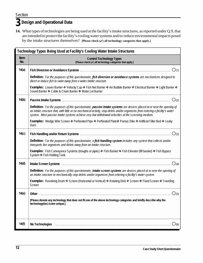
14. What types of technologies are being used at the facility’s intake structures, as reported under Q.9, thatare intended to protect the facility’s cooling water systems and/or reduce environmental impacts posedby the intake structures themselves? [Please check (����) all technology categories that apply.]
Technology Types Being Used at Facility’s Cooling Water Intake Structures
ItemNo.
Control Technology Types[Please check (����) all technology categories that apply.]
14(a) Fish Diversion or Avoidance Systems . . . . . . . . . . . . . . . . . . . . . . . . . . . . . . . . . . . . . . . . . . . . . . . . . . . . . . . . . . . . �(1)
Definition: For the purposes of this questionnaire, fish diversion or avoidance systems are mechanisms designed todivert or induce fish to swim away from a water intake structure.
Examples: Louver Barrier � Velocity Cap � Fish Net Barrier � Air Bubble Barrier � Electrical Barrier � Light Barrier �Sound Barrier � Cable & Chain Barrier � Water Jet Barrier
14(b) Passive Intake Systems . . . . . . . . . . . . . . . . . . . . . . . . . . . . . . . . . . . . . . . . . . . . . . . . . . . . . . . . . . . . . . . . . . . . . . . . �(2)
Definition: For the purposes of this questionnaire, passive intake systems are devices placed at or near the opening ofan intake structure that, with little or no mechanical activity, stop debris and/or organisms from entering a facility’s watersystem. Most passive intake systems achieve very low withdrawal velocities at the screening medium.
Examples: Wedge Wire Screen � Perforated Pipe � Perforated Plate� Porous Dike � Artificial Filter Bed � LeakyDam
14(c) Fish Handling and/or Return Systems . . . . . . . . . . . . . . . . . . . . . . . . . . . . . . . . . . . . . . . . . . . . . . . . . . . . . . . . . . . . �(3)
Definition: For the purposes of this questionnaire, a fish handling system includes any system that collects and/ortransports live organisms and debris away from an intake structure.
Examples: Fish Conveyance Systems (troughs or pipes) � Fish Basket � Fish Elevator (lift basket) � Fish BypassSystem � Fish Holding Tank
14(d) Intake Screen Systems . . . . . . . . . . . . . . . . . . . . . . . . . . . . . . . . . . . . . . . . . . . . . . . . . . . . . . . . . . . . . . . . . . . . . . . . �(4)
Definition: For the purposes of this questionnaire, intake screen systems are devices placed at or near the opening ofan intake structure to mechanically stop debris and/or organisms from entering a facility’s water system.
Examples: Revolving Drum � Screen (Horizontal or Vertical) � Rotating Disk � Screen � Fixed Screen � TravelingScreen
14(e) Other . . . . . . . . . . . . . . . . . . . . . . . . . . . . . . . . . . . . . . . . . . . . . . . . . . . . . . . . . . . . . . . . . . . . . . . . . . . . . . . . . . . . . . . �(5)
[Please denote any technology that does not fit one of the above technology categories and briefly describe why thetechnology(ies) is/are unique.]
14(f) No Technologies . . . . . . . . . . . . . . . . . . . . . . . . . . . . . . . . . . . . . . . . . . . . . . . . . . . . . . . . . . . . . . . . . . . . . . . . . . . . . �(6)
Section
Design and Operational Data 3
Case Study Short Questionnaire 13
�Yes (1)
�No (2)SKIP TO Q.16, Page 15
15. (a) Has your facility or its firm owner ever conducted orcommissioned a study of the ecological or environmentaleffects of any of the facility’s intake structures that havewithdrawn surface water for contact or noncontact coolingpurposes (i.e., those intake structures reported under Q.9)?
(b) Please provide the name of the most recent study completed.In addition, please provide the name and telephone numberof the individual(s) we should contact if we requireadditional information regarding the study.
Name of Most Recent Study: ____________________ (1)
Contact Name: _______________________________ (2)
Telephone Number: ( )______________________ (3)
Section
3 Design and Operational Data
14 Case Study Short Questionnaire
THIS PAGE INTENTIONALLY LEFT BLANK

Section
Facility and Firm-Level Economic Data 4
Case Study Short Questionnaire 15
�Yes (1)
�No (2)SKIP TO Q.21, Page 19
DEFINITION For the purposes of this questionnaire, a domesticparent firm is the highest level domestic business entity
in the facility’s organizational structure. A firm that is owned by anotherU.S. firm is not a domestic parent firm. A U.S. firm that is owned by aforeign firm is a domestic parent firm.
Section 4: Facility and Firm-Level Economic Data
CBI?� 16. Please complete the matrix below with the facility’s number ofemployees and total annual sales revenue for the facility’s FiscalYear 1997.
Full-Time Equivalent (FTE) Employees and Annual Sales Revenue for Facility(for Facility’s Fiscal Year 1997)
ItemNo. Data Requested Response
16(a) Number of FTE Employees, Including Full-Time and Part-Time Employees [You mayround to the nearest 10 employees.]
Definition: For the purposes of this questionnaire, one FTE employee equals oneperson-year or 2,000 hours.
__________________
16(b) Total Annual Sales Revenue (in whole U.S. dollars) [If the facility operates as a costcenter for a larger parent firm and facility-level revenue is not available, indicate NA (fornot applicable).]
Definition: For the purposes of this questionnaire, total annual sales revenue is thetotal amount of money received by a firm from sales of its products and/or services over365 days. The value does not include gains from investments or extraordinary gains,such as increases in owners’ equity from capital adjustments or gains from the sale orexchange of assets.
$_________________
NA....................�(9)
17. (a) As of the last day of the facility’s Fiscal Year 1997, was thefacility owned by another entity?
NOTE: Please answer “yes” to this question if your facility was owned byan entity, other than the facility itself, such as another firm or organization,a limited partnership, a joint venture, or a government entity.”
CBI?� (b) Please provide the complete legal name, address, and DUNSnumber for the domestic parent firm that owned the facilityas of the last day of the facility’s Fiscal Year 1997.
NOTE: If the facility was owned by a joint venture or is under another typeof joint ownership, please provide the information for the owner that held thelargest share in the facility. If the facility was owned by a foreign entity,please put “foreign” under “Name of Domestic Parent Firm” and skip to Q.21(a).

Section
4 Facility and Firm-Level Economic Data
16 Case Study Short Questionnaire
�Yes (1)
�No (2)SKIP TO Q.20, Page 17
DEFINITION
�SKIP TO Q.21, Page 19
For the purposes of this questionnaire, the total annualsales of electricity is the sum of electricity sales to
ultimate consumers and sales of electricity for resale.
Name of Domestic Parent Firm: _________________ (1)
Street Address: _______________________________ (2)
P.O. Box (if applicable): ________________________ (3)
City, State ZIP: ______________________________ (4)
DUNS Number: __ __ – __ __ __ – __ __ __ __ (5)
[� Check (�) here if none.]
18. What are the four-digit SIC codes associated with the domesticparent firm’s main lines of business? [Please use the SIC codescontained in the Office of Management and Budget’s 1987 Standard IndustrialClassification Manual. This listing can also be found at the following Internetsite: www.osha.gov/cgi-bin/sic/sicser5.]
Primary __ __ __ __ (1)
Secondary __ __ __ __ (2)
Other __ __ __ __ (3a) __ __ __ __ (3b) __ __ __ __ (3c)
19. (a) Is the domestic parent firm’s primary SIC code 4911?
CBI?� (b) During the facility’s Fiscal Year 1997, what were the totalannual sales of electricity by all facilities owned by thedomestic firm (in megawatt hours or MWh)? [Please check (����)only one response.]
Less than 150,000 MWh: . . . . . . . . . . . . . . . . . . . . . . . . �(1)
150,000 to 4 million MWh: . . . . . . . . . . . . . . . . . . . . . . . �(2)
More than 4 million MWh: . . . . . . . . . . . . . . . . . . . . . . . �(3)

Section
Facility and Firm-Level Economic Data 4
Case Study Short Questionnaire 17
CBI?� 20. Please complete the following matrix with the domestic parent firm’s number of employees and totalannual sales revenue for the facility’s Fiscal Year 1997.
FTE Employees and Annual Sales Revenue for Domestic Parent Firm(for Facility’s Fiscal Year 1997)
ItemNo. Data Requested Response
20(a) Number of FTE Employees, Including Full-Time and Part-Time Employees[You may round to the nearest 10 employees.] _______________________
20(b) Total Annual Sales Revenue (in whole U.S. dollars) $______________________

18 Case Study Short Questionnaire
THIS PAGE INTENTIONALLY LEFT BLANK

Section
Facility Production and Electricity Generation Data 5
Case Study Short Questionnaire 19
�Yes (1)
�No (2) STOPIf answer is No, pleasestop here and returnquestionnaire with acompleted CertificationStatement.
�Yes (1)
�No (2) STOPIf answer is No, pleasestop here and returnquestionnaire with acompleted CertificationStatement.
Section 5: Facility Production and Electricity Generation DataCBI?� 21. (a) Did your facility generate electricity at any time during the
facility’s Fiscal Years 1995, 1996, or 1997?
(b) Did your facility generate electricity using cooling waterdirectly withdrawn by the facility from surface water at anytime during the facility’s Fiscal Years 1995, 1996, or 1997?
NOTE: Cooling water may be derived from several sources and canbe commingled before being used for cooling purposes. If any portionof commingled cooling water was derived from surface water throughthe facility’s own intake structures, it should be considered coolingwater directly withdrawn from surface water for the purposes of thisquestionnaire.
CBI?� 22. Please provide the information requested in the matrix below forthe facility’s Fiscal Year 1997. [If FY 1997 was not a typical year interms of the facility’s electricity generation activities, please provide therequested information for a typical fiscal year in the previous two years. Pleasealso note the fiscal year for which the data are being provided.]
Facility Electricity Generation and Sales for Facility’s Fiscal Year 1997or Other Recent Typical Fiscal Year
ItemNo. Data Requested Response
22(a) Typical Facility Fiscal Year for Which Data in Matrix Are Being Provided[Please check (����) one fiscal year only.]
Fiscal Year 1995 . . . . . . . . . . . . . �(1)
Fiscal Year 1996 . . . . . . . . . . . . . �(2)
Fiscal Year 1997 . . . . . . . . . . . . . �(3)
22(b) Gross Electricity Generated by Facility Using Cooling Water DirectlyWithdrawn by Facility from Surface Water (in kilowatt hours or kWh)
________________________ kWh
22(c) Total Annual Sales of Electricity Generated Using Cooling Water DirectlyWithdrawn from Surface Water by Facility (including sales to ultimateconsumers and sales for resale (in kWh)) [Use the formula below to calculateyour response.]
Gross Electricity Generated by FacilityUsing Cooling Water Withdrawn Surface Water
Total Electricity Generated by Facility× Facility's Total Sales of Electricity (in kWh)
________________________ kWh
THANK YOU FOR COMPLETING EPA’S CASE STUDY SHORT QUESTIONNAIRE. WE APPRECIATE YOURCOOPERATION. PLEASE RETURN THE QUESTIONNAIRE WITH A SIGNED CERTIFICATION STATEMENTIN THE ENVELOPE PROVIDED.

Section
5 Facility Production and Electricity Generation Data
20 Case Study Short Questionnaire
THIS PAGE INTENTIONALLY LEFT BLANK

Glossary of Terms
Case Study Short Questionnaire G-1
Plan View
Glossary of Terms
NOTE: The following terms are defined for purposes of this questionnaire only. The definitions at present do not haveany legal meaning with respect to Section §316(b).
Air Conditioning: The process and equipment used to control the temperature and humidity of indoorair. Cooling water is used in some types of air conditioning systems.
Average Daily Intake Flow Rate: The total volume of cooling water withdrawn by a specific intakestructure over a 24-hour day.
Bar Rack/Trash Rack: A device placed at or near the opening of an intake structure to mechanicallystop debris and /or large organisms from entering a facility’s water system.
Bay or Cove (natural): An inlet created when the shoreline of a water body is indented. Bays aregenerally larger than coves but are smaller than gulfs. Coves are generally sheltered. See Figure 1 for agraphical view of an intake structure incorporating a bay or cove. [See also definition for intake embayment/bay/cove.]
Figure 1. Example of an Intake Structure Incorporating a Bay or Cove
Combined Cycle Unit: An electric generating unit that has one or more gas turbine or internalcombustion engines and one or more steam boilers. Part of the required input to the boiler(s) isprovided by the exhaust gas (waste heat) of the combustion turbine(s).
Cooling Canal/Channel: An artificial, channelized waterway used to transfer heat added to waterfrom operations within a facility to the atmosphere.
Cooling Lake: An expanse of water, generally surrounded by land and an artificial retainer such as adam. It is used to transfer heat added to water from operations within a facility to the atmosphere. Cooling lakes are used with both once-through and recirculating cooling water systems.

G-2 Case Study Short Questionnaire
Cooling Operations: Activities that transfer heat from one medium or activity to cooling water (withthe exception of nonprocess air conditioning).
Cooling Pond: A still body of water generally constructed on dry land. Its primary purpose is totransfer heat added to water from operations within a facility to the atmosphere. Constructed coolingponds are often larger than many natural lakes. They are used with both once-through and recirculatingcooling water systems.
Cooling Tower: A framed structure that is typically higher than its width. It can stand apart or beattached to a larger structure. Cooling towers are used to transfer heat added to water from operationswithin a facility to the atmosphere. Cooling towers can be used with recirculating cooling watersystems where the entire discharge flow is returned to the facility. They can also be used withnonrecirculating systems to treat all or a portion of the discharge flow from a facility where it isultimately returned to the receiving water body.
Cooling Water: Water used for both contact and noncontact cooling purposes, including water usedfor air conditioning, equipment cooling, evaporative cooling tower makeup, and dilution of effluentheat content. The intended use of the cooling water is to absorb waste heat rejected from the process orprocesses employed or from auxiliary operations on the facility’s premises.
Cooling Water Intake Structure: The total structure and associated technologies used to direct waterfrom a water body into a facility up to the point of the first intake pump or series of pumps. Theintended use of the cooling water is to absorb waste heat rejected from processes employed or fromauxiliary operations on the facility’s premises. Single cooling water intake structures might havemultiple intake bays. If a facility has an intake structure that withdraws water for other purposes inaddition to cooling, the entire intake structure should be considered a cooling water intake structure forpurposes of this questionnaire.
Cooling Water System: A system that provides water to/from a facility to transfer heat fromequipment or processes therein. The system includes, but is not limited to, water intake and outletstructures, cooling towers, ponds, pumps, pipes, and canals/channels. For facilities that use surfacewater for cooling, a system begins at the first barrier to ingress and/or egress by fish and other aquaticwildlife (e.g., at the trash rack, etc.) and ends at the discharge outlet(s). See also Cooling Water IntakeStructure.
Design Through-Screen Velocity: The value assigned during the design phase of a CWIS to thespeed at which intake water passes through the cooling water intake screen (or other technology)against which organisms may be impinged or where they may be entrained.
Discharge: Outflow of wastewater from a facility to waters of the United States.
Domestic Parent Firm: The highest level domestic business entity in a facility’s organizationalstructure. A firm that is owned by another U.S. firm is not a domestic parent firm. A U.S. firm that isowned by a foreign firm is a domestic parent firm.

Glossary of Terms
Case Study Short Questionnaire G-3
DUNS Number: A number assigned to a business using the Data Universal Numbering System(DUNS) developed by the Dun and Bradstreet Corporation.
Effluent: Outflow of wastewater from a facility to waters of the United States.
Estuary: A semi-enclosed coastal body of water that has a free connection with the open sea and isstrongly affected by tidal action. In an estuary, sea water is mixed (and usually measurably diluted)with fresh water inflow from rivers. (NOTE: The Chesapeake Bay and the San Francisco Bay are examples of estuarieseven though the term bay appears in their names.)
Fish Diversion or Avoidance System: Mechanisms designed to divert or induce fish to swim awayfrom a water intake structure.
Fish Handling and/or Return System: Any system that collects and/or transports live organisms anddebris away from an intake structure.
Full-Time Equivalent Employee (FTE): The normalized unit for counting employees at a facility. One FTE equals 2,000 hours of work (8 hours per day for 250 days) during a calendar year. As such,two part-time employees, each working 1,000 hours per year, would be counted together as one FTE.
Generating Unit: A combination of physically connected generator(s), reactor(s), boiler(s),combustion turbine(s), or other prime mover(s) operated together to produce electric power.
Gross Electricity Generation: The total amount of electric energy produced by the generating unitsof a given facility.
Groundwater Injection Well: A man-made or improved “hole” in the ground that is deeper than itswidest surface dimension and is used to discharge or dispose of fluids to groundwater (the supply ofwater found beneath the earth’s surface; it is usually held in aquifers and is often the source of waterfor streams, springs, or wells from which it may be withdrawn). There are many types of injectionwells, but they are all similar in their basic function. The Federal Underground Injection ControlProgram has grouped injection wells into five categories—Class I through V wells.
Intake Bays: Temporary holding areas designed to direct water toward the pump well of a specificintake structure.
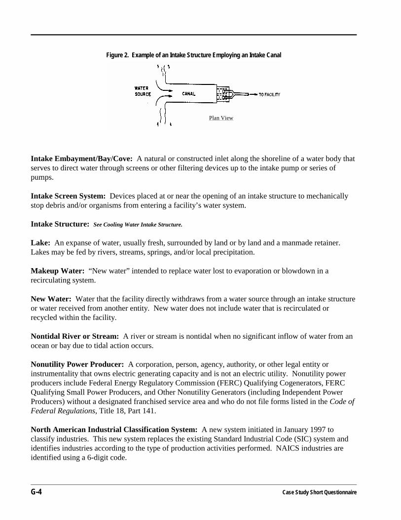
Intake Canal/Channel (natural or constructed): A channelized conduit that directs water throughscreens or other filtering devices up to the intake pump or series of pumps. See Figure 2 for a graphical viewof an intake structure employing an intake canal.
G-4 Case Study Short Questionnaire
Plan View
Figure 2. Example of an Intake Structure Employing an Intake Canal
Intake Embayment/Bay/Cove: A natural or constructed inlet along the shoreline of a water body thatserves to direct water through screens or other filtering devices up to the intake pump or series ofpumps.
Intake Screen System: Devices placed at or near the opening of an intake structure to mechanicallystop debris and/or organisms from entering a facility’s water system.
Intake Structure: See Cooling Water Intake Structure.
Lake: An expanse of water, usually fresh, surrounded by land or by land and a manmade retainer. Lakes may be fed by rivers, streams, springs, and/or local precipitation.
Makeup Water: “New water” intended to replace water lost to evaporation or blowdown in arecirculating system.
New Water: Water that the facility directly withdraws from a water source through an intake structureor water received from another entity. New water does not include water that is recirculated orrecycled within the facility.
Nontidal River or Stream: A river or stream is nontidal when no significant inflow of water from anocean or bay due to tidal action occurs.
Nonutility Power Producer: A corporation, person, agency, authority, or other legal entity orinstrumentality that owns electric generating capacity and is not an electric utility. Nonutility powerproducers include Federal Energy Regulatory Commission (FERC) Qualifying Cogenerators, FERCQualifying Small Power Producers, and Other Nonutility Generators (including Independent PowerProducers) without a designated franchised service area and who do not file forms listed in the Code ofFederal Regulations, Title 18, Part 141.
North American Industrial Classification System: A new system initiated in January 1997 toclassify industries. This new system replaces the existing Standard Industrial Code (SIC) system andidentifies industries according to the type of production activities performed. NAICS industries areidentified using a 6-digit code.
Glossary of Terms
Case Study Short Questionnaire G-5
NPDES (National Pollutant Discharge Elimination System) Permit: A permit required to be heldunder Section 402 of the Clean Water Act (33 U.S.C. 1342 et seq.) by any point source dischargingpollutants directly to waters of the United States. Permits may address effluent discharges, stormwater, or sewage sludge management practices and may be issued by an EPA Region or a Federally-approved State NPDES program.
Ocean: Marine open coastal waters other than those water bodies classified as estuaries, embaymentsor fjords, each of which are semi-enclosed and have readily identifiable geographic boundaries.
Once-through Cooling Water System: A system designed to withdraw water from a natural or otherwater source, run it through a facility for contact and/or noncontact cooling purposes, and thendischarge it to a water body without recirculation. Once-through cooling water systems may usenonrecirculating canals/channels, lakes, ponds, or towers to “help” dissipate waste heat from the waterbefore it is discharged.
Operating Days: The total number of days (1 day = 24 hours) a cooling water intake structureoperated during a specified time period, excluding any days the cooling water intake structure wasoffline for routine maintenance or otherwise was not operational. A partial day (i.e., operations of lessthan 24 hours) does not constitute an operating day and should not be counted as such.
Passive Intake System: Devices placed at or near the opening of an intake structure that, with little orno mechanical activity, stops debris and/or organisms from entering a facility’s water system. Mostpassive intake systems achieve very low withdrawal velocities at the screening medium.
Planned or Under Construction: Cooling water intake structures or cooling water systems for whichfunds have been authorized and that are expected to go into commercial service within the next 7 years. The term does not include intake structures or cooling water systems that are presently operating,temporarily offline, permanently offline, or operating under test conditions.
Point Source: Any discernible, confined, and discrete conveyance, including but not limited to, anypipe, ditch, channel, tunnel, conduit, well, discrete fissure, container, rolling stock, concentrated animalfeeding operation, landfill leachate collection system, vessel or other floating craft from whichpollutants are or may be discharged. The term does not include return flows from irrigated agricultureor agricultural storm water run off. See also 40 CFR 122.2.
Pond: A still body of water generally smaller than a lake.
Presently Operating: Cooling water intake structures or cooling water systems currently taking inwater for cooling purposes.
Prime Mover: The engine, turbine, water wheel, or similar machine that drives an electric generator. It can also be a device that directly converts energy to electricity such as a photovoltaic solar cell or afuel cell.
G-6 Case Study Short Questionnaire
Privately-owned Treatment Works: A device or system which is (a) used to treat wastes from anyfacility whose operator is not the operator of the treatment works and (b) is not a publicly-ownedtreatment works.
Process Operations: Industrial activities that directly result in the production of a facility’s primaryoutput.
Production Line: Each of the successive steps taken at a facility to produce a product, except theproduction line’s use of electricity.
Publicly-owned Treatment Works: A treatment works owned by a State or municipality. The termrefers to any devices and systems used to store, treat, recycle, and reclaim municipal sewage orindustrial wastes of a liquid nature. It also refers to sewers, pipes, and other conveyances only if theyconvey wastewater to a POTW.
Recirculating Cooling Water System: A system designed to withdraw water from a natural or otherwater source to support contact and noncontact cooling uses within a facility. The water is generallysent to a cooling canal/channel, lake, pond, or tower in order for waste heat to be dissipated. (Somefacilities may divert the “waste heat” to other process operations.) Once accomplished, the water isreturned to the system. New source water (called makeup water) is added to the system to replenishlosses that have occurred due to blowdown, drift, and evaporation.
Reservoir: An artificial body of surface water retained by a dam.
Standard Industrial Classification (SIC) Code: A national classification system that organizesbusiness entities into production-based and market-based categories identified by a 4-digit code. Sincethe 1930s, SIC codes have been used to facilitate the collection, tabulation, presentation, and analysisof data relating to U.S. business establishments by Federal statistical agencies (e.g., Office ofManagement and Budget or OMB, Bureau of the Census, etc.). The system was last updated by OMBin 1987. It was recently replaced by the North American Industry Classification System (NAICS) in1997; however, it continues to be used by many Federal agencies such as EPA. An SIC listing can befound at the following Internet site: www.osha.gov/cgi-bin/sic/sicser5.
Steam Electric Generating Unit: A generating unit in which the prime mover is a steam turbine. Theturbines convert thermal energy (steam or hot water) produced by the generators or boilers tomechanical energy or shaft torque. The mechanical energy is then used to power electric generatorswhereby the mechanical energy is converted to electricity.
Storm Water: The term refers to rainfall runoff, snow melt runoff, and surface runoff and drainage.
Submerged Intake Structure Flush with the Shoreline: An intake structure whose opening isclosely aligned with the shoreline and that always withdraws water from below the surface of the waterbody. See Figure 3 for a graphical view of a submerged intake structure flush with the shoreline.

Glossary of Terms
Case Study Short Questionnaire G-7
Plan View Cross Section
Figure 3. Example of a Submerged Intake Structure Flush With Shoreline
Plan View Cross Section
Figure 4. Example of a Submerged Offshore Intake Structure
Plan View Cross Section
Figure 5. Example of a Surface Intake Structure Flush with Shoreline
Submerged Offshore Intake Structure: An intake structure that extends from a facility outward intoa water body. The intake opening is submerged, and the water withdrawn is always from below thesurface of the water body. See Figure 4 for a graphical view of a submerged offshore intake structure.
Surface Intake Structure Flush with the Shoreline: An intake structure whose opening is evenlyaligned with the shoreline and that generally withdraws water from the surface of a water body. SeeFigure 5 for a graphical view of a surface intake structure flush with the shoreline.
Surface Water: The term includes lakes, ponds, or reservoirs; nontidal rivers or streams; tidal rivers;estuaries; fjords; oceans; and bays/coves.

G-8 Case Study Short Questionnaire
Temporarily Offline: Cooling water intake structures or cooling water systems presently out ofcommercial service but expected to return to service. The category includes systems or intakestructures on inactive reserve and deactivated (i.e., systems or intake structures not normally used butavailable for service).
Tidal River: A tidal river is the portion of the river above the river’s mouth that receives a regular,significant inflow of water from an ocean or bay due to tidal action.
Total Annual Sales of Electricity: The sum of electricity sales to ultimate consumers and sales ofelectricity for resale.
Total Annual Sales Revenue: The total amount of money received by a firm from sales of itsproducts and/or services over 365 days. The value does not include gains from investments orextraordinary gains, such as increases in owners’ equity from capital adjustments or gains from thesale or exchange of assets.
Trash Rack: See Bar Rack.
Typical Calendar Year: A year in which the facility and its cooling water intake structures areoperated in a normal, routine, regular, or otherwise standard fashion.
Water Body: For purposes of this questionnaire, water body refers to surface water used by coolingwater intake structures. The term includes oceans, lakes, reservoirs, rivers, streams, fjords, ponds,bays/coves, and estuaries.
Waters of the United States: All waters which are currently used, were used in the past, or may besusceptible to use in interstate or foreign commerce, including all waters which are subject to the ebband flow of the tide. Waters of the United States include, but are not limited to, all interstate watersand intrastate lakes, rivers, streams (including intermittent streams), mudflats, wetlands, sloughs,prairie potholes, wet meadows, playa lakes, or natural ponds. See 40 CFR 122.2 for a more complete definition.