Embed Size (px)
Citation preview

Python Tutorial
Case Study: Investigation of Nuisance Tripping in a 200 MW Wind Farm
2016 PSCAD® User Group Meeting
Houston, TX
Oct 6 - 7, 2016
Ketut Dartawan , Amin M Najafabadi
Project’s specification and history of the event
1-2
Outline
Scope of the study
Considered scenarios
Time domain simulations
Discussion about harmonic and Inter-harmonics
Frequency domain simulation results
Conclusion
200 MW DFIG wind farm connected to 345 KV system.
95 WTG distributed on eight 34.5 KV collector feeders.
Project includes 4x12 MVAR cap banks (on 34.5 KV collector
buses) to meet LGIA PF requirement.
Project experienced nuisance tripping of WTGs during cap banks
switching.
Trip signals recorded by WTGs indicate power quality and
harmonic distortion issues.
Harmonic distortion study of the Project did not indicate potential
violations.1-3
Project Info
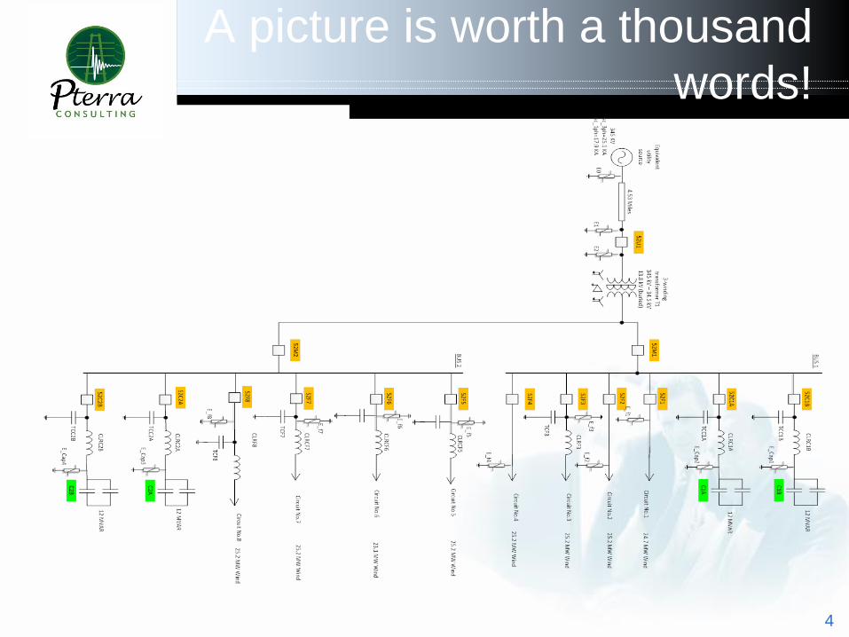
A picture is worth a thousand
words!
4
Scope of the Study
Develop a detailed model of the Project using PSCAD.
Developed model should take into account background distortion and
include sufficient details to capture transient waveform developed on
collector system following cap bank switching.
Study various cap banks switching events and monitor output of WTGs
at 690 V side of GSUs.
For each scenario, evaluate harmonic and interharmonic distortions
seen by WTGs
Identify sensitivity of results with respect to grid short circuit capability,
Project’s dispatch and #WTGs in service.
5
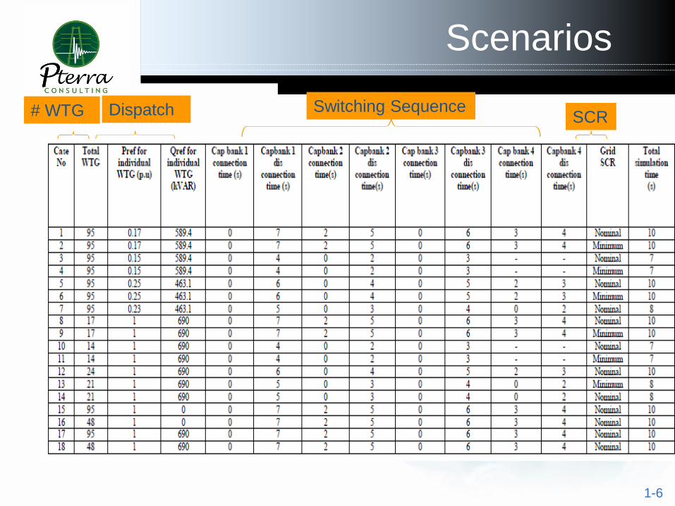
Scenarios
1-6
# WTG Dispatch Switching SequenceSCR
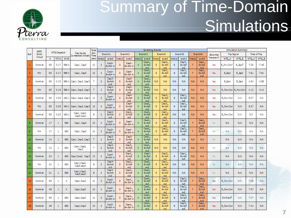
Summary of Time-Domain
Simulations
7
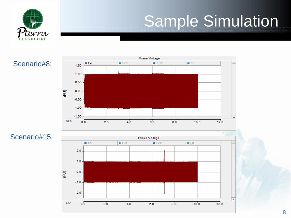
Sample Simulation
8
Scenario#8:
Scenario#15:
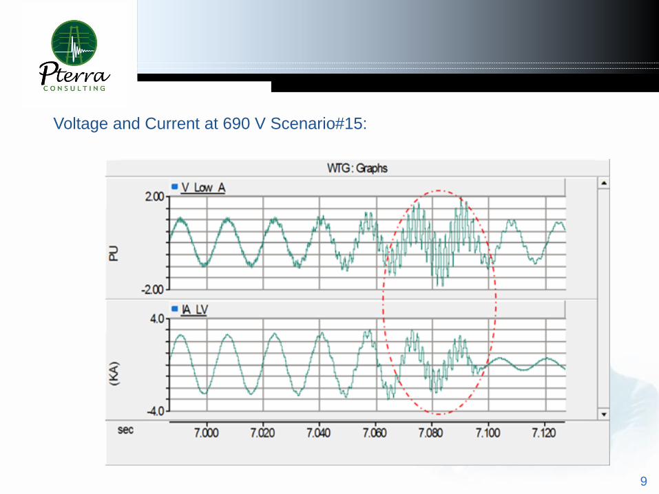
9
Voltage and Current at 690 V Scenario#15:
Passive Frequency
Scan
1-10
Passive Frequency
Scan
1-11
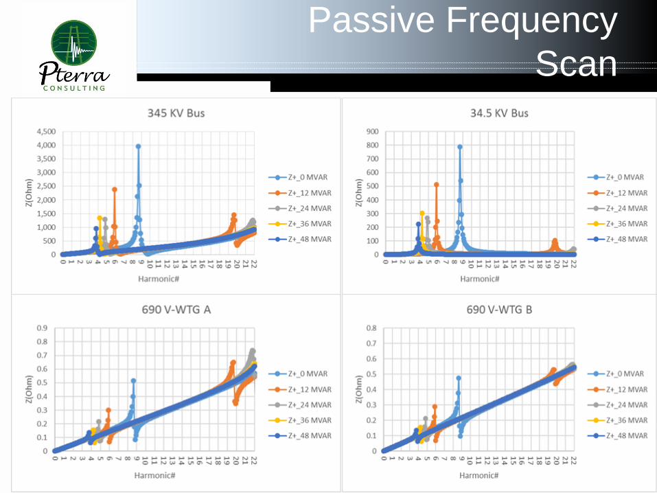
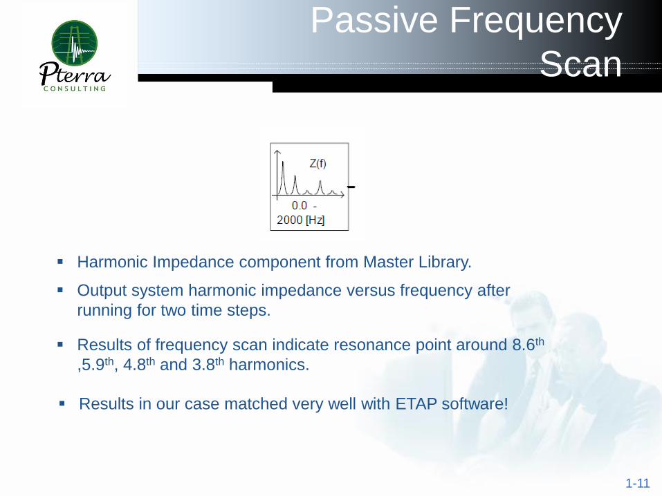
Harmonic Impedance component from Master Library.
Output system harmonic impedance versus frequency after
running for two time steps.
Results in our case matched very well with ETAP software!
Results of frequency scan indicate resonance point around 8.6th
,5.9th, 4.8th and 3.8th harmonics.
Harmonics &
Interharmonics
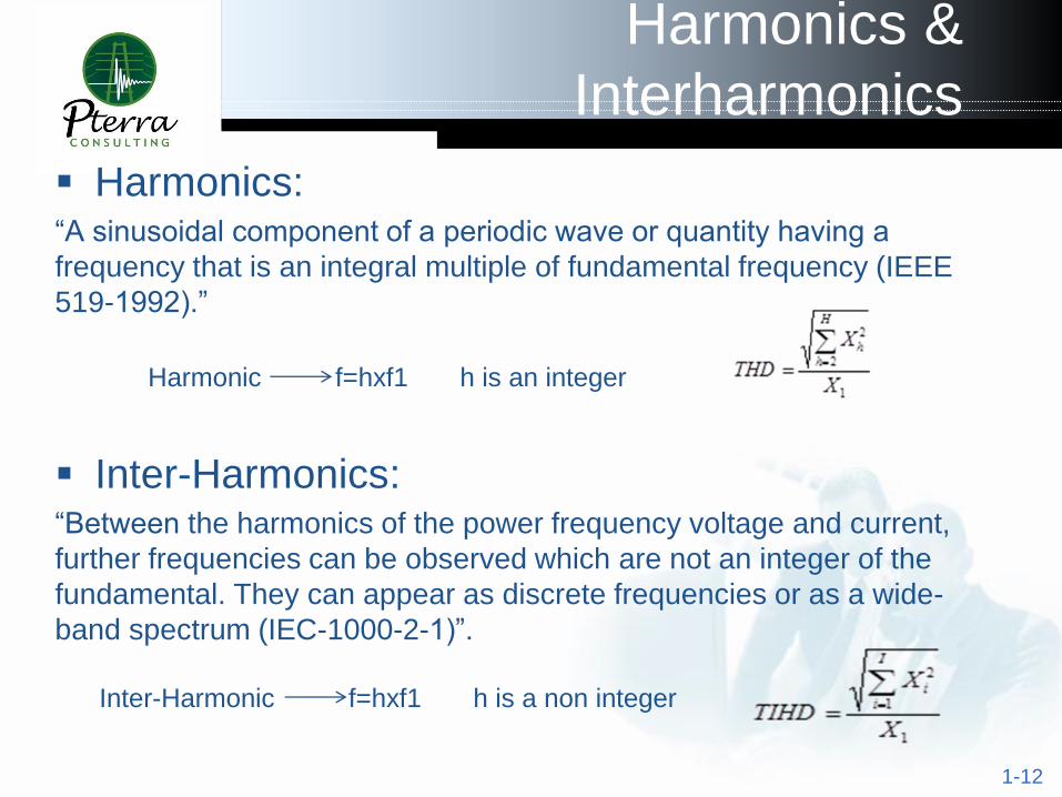
Harmonics: “A sinusoidal component of a periodic wave or quantity having a
frequency that is an integral multiple of fundamental frequency (IEEE
519-1992).”
Inter-Harmonics: “Between the harmonics of the power frequency voltage and current,
further frequencies can be observed which are not an integer of the
fundamental. They can appear as discrete frequencies or as a wide-
band spectrum (IEC-1000-2-1)”.
1-12
Harmonic f=hxf1 h is an integer
Inter-Harmonic f=hxf1 h is a non integer
Interharmonic Sources
& Impacts
13
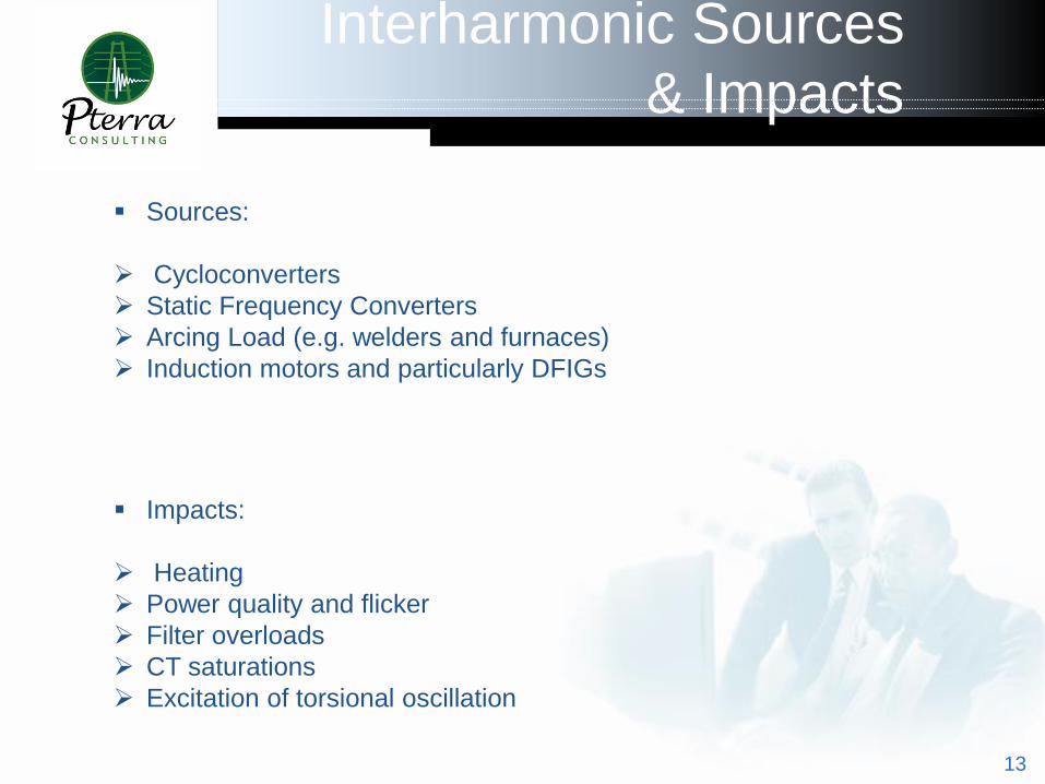
Sources:
Cycloconverters
Static Frequency Converters
Arcing Load (e.g. welders and furnaces)
Induction motors and particularly DFIGs
Impacts:
Heating
Power quality and flicker
Filter overloads
CT saturations
Excitation of torsional oscillation

Measurement
1-14
A waveform consisting of inter-harmonics might not be periodic.
End-effect errors are encountered if sampled waveform is not
periodic over sampling interval. DFT based on single cycle
samples can yield inaccurate results if waveform includes
interharmonic components.
Windowing functions and zero padding can be used to minimize
end-effects and increase frequency resolution.
Most of the measurement methods that are being used today are
based on FFT/DFT.
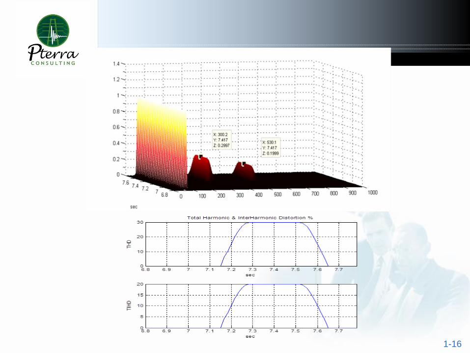
IEC 61000-4-7 recommends measurement interval of twelve
cycles for calculation of interharmonics in 60 Hz system.
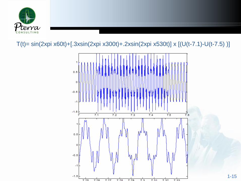
1-15
T(t)= sin(2xpi x60t)+[.3xsin(2xpi x300t)+.2xsin(2xpi x530t)] x [(U(t-7.1)-U(t-7.5) )]
1-16
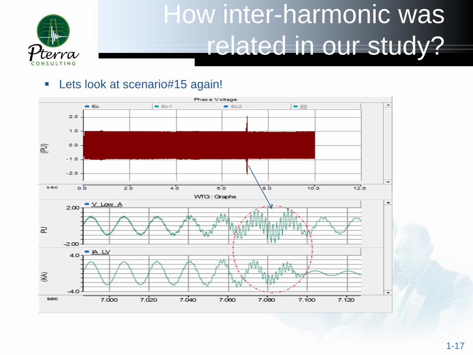
How inter-harmonic was
related in our study?
1-17
Lets look at scenario#15 again!
1-18
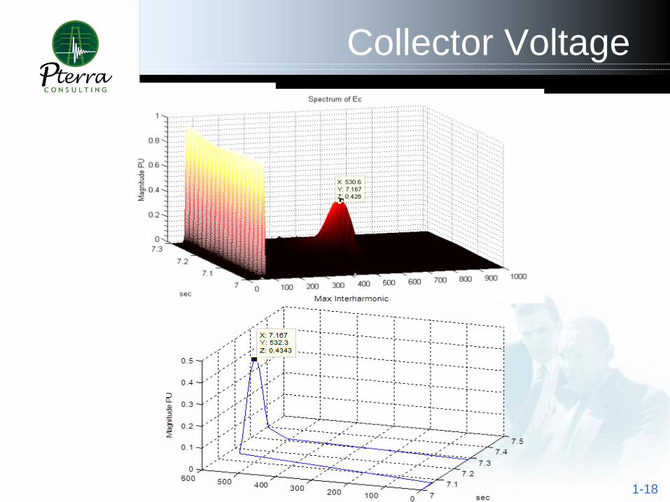
Collector Voltage
1-19
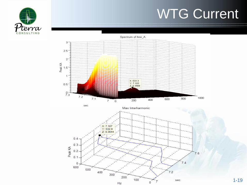
WTG Current
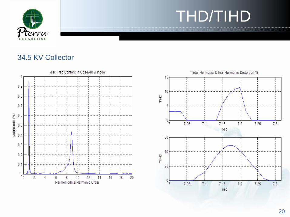
THD/TIHD
20
34.5 KV Collector

21
Voltage at 690 V WTG Terminal Current at 690 V WTG Terminal

22
Processing time-domain waveforms of switching scenarios indicated
considerable inter-harmonic distortion in all problematic scenarios.
Scenario# 1 2 3 4 5 6 7 15 16 17 18
#WTGs 95 95 95 95 95 95 95 95 48 95 48
WTG_ Dispatch
(PU)0.17 0.17 0.15 0.15 0.25 0.25 0.23 1 1 1 1
GRID_SCR Nom Min Nom Min Nom Min Nom Nom Nom Nom Nom
From_ Time (sec) 7 7 4 4 6 6 5 7 7 7 7
To_ Time (sec) 7.5 7.8 4.8 4.4 6.3 6.6 5.5 7.3 7.8 7.3 7.7
Estimated
Interharmonic
Frequency (Hz)
532 515 531 514 531 515 532 532 490 532 489

1-23
Conclusion
Capacitor bank switching events were studied for a 200 MW
wind farm composed of ninety five 2.1 MW DFIGs. Study was
aimed to illustrate the root cause of nuisance WTG tripping
observed in the field.
Time domain simulations indicated abnormal transients
following cap bank switching. Abnormal transients were
initiated short after last cap bank in service was switched out.
Frequency processing of time-domain signals indicated high
inter harmonic distortions. This observation was in line with
field measurements and control signals recorded by actual
WTGs.
Close proximity of Inter harmonic currents generated by
WTGs to resonance point of the system was identified as the
root cause of abnormal temporary overvoltages.

1-24
Conclusion
Simulation of various scenarios indicated:
High sensitivity of results with respect to #WTGs in service.
Abnormal transient overvoltage was developed on 34.5 KV
collector in all cases where at least of half of WTGs were in
service.
o Change of the grid short circuit capability in the range
studied (i.e. minimum and nominal) impacted time domain
waveform but it did not cause nor eliminate abnormal
transient phenomenon.

1-25