Embed Size (px)
Citation preview

Case study
Failure analysis of mixed mode crack growth in heavy dutytruck frame rail
Vinay N. Rao *, Jeffrey W. Eischen
North Carolina State University, Raleigh, 27606 NC, USA
1. Introduction
A failure in a heavy duty truck frame generally involves crack growth under mixed mode I/II/III loading since the vehicleloads are highly nonlinear transient and multi-axial with large deformation behavior. This is similar to many mixed modecrack growth problems reported in literature [1–9]. The propagation of cracks in truck frame members is important to bewell studied since on reaching critical crack lengths it can lead to complete breakdown of the vehicle and this may lead tocatastrophic accidents with loss of life. Although there are routine vehicle inspections currently in place to detect and repair/replace fatigue cracked components, the ability to better predict crack path and orientation under various loading conditionscan help avoid expensive losses and improve the design with better durability.
In this work, failure analysis of frame rail crack was carried out. Through careful macroscopic and microscopicobservations, the crack was found to be primarily caused due to aggressively drilled open-hole close to an existing bolthole. The drilled hole created small crack initiations within a high stress location of the frame. FRANC3D crack growthsimulation tool combined with NASTRAN finite element solver was used in this work to simulate frame crack growthunder full vehicle dynamic loads. The simulation results obtained showed good correlation to physical crack path andcycles to failure.
Case Studies in Engineering Failure Analysis 5–6 (2016) 67–74
A R T I C L E I N F O
Article history:
Received 18 January 2016
Received in revised form 12 March 2016
Accepted 29 March 2016
Available online 6 April 2016
Keywords:
Fatigue
Frame rail failure
Crack growth simulation
Fracture
Finite element analysis
A B S T R A C T
A failure analysis investigation was performed on a fractured heavy duty truck frame rail
obtained during endurance track testing. The fracture observed was on the frame web
within the torque rod connection to the rear drive axle of the vehicle. This section of frame
experiences multi-axial loading conditions including out-of-plane bending, twisting and
shear under road loads. Metallographic examination revealed micro-cracks on the edges of
an open hole located in an area of high stress concentration. This manufacturing defect
acted as a stress raiser and resulted in fatigue crack initiation. Simulation of crack growth
on frame rail using dynamic loads from a full vehicle model was completed. After careful
analysis it was concluded that the failure occurred due to an aggressively drilled open hole
which created small crack initiations in a high stress-state location of the frame. This
resulted in extensive curvilinear crack growth under dynamic loads of the vehicle.
� 2016 The Authors. Published by Elsevier Ltd. This is an open access article under the CC
BY-NC-ND license (http://creativecommons.org/licenses/by-nc-nd/4.0/).
* Corresponding author. Tel.: +1 2604456357.
E-mail address: [email protected] (V.N. Rao).
Contents lists available at ScienceDirect
Case Studies in Engineering Failure Analysis
jo ur n al ho m ep ag e: ww w.els evier . c om / lo cat e/c s efa
http://dx.doi.org/10.1016/j.csefa.2016.03.002
2213-2902/� 2016 The Authors. Published by Elsevier Ltd. This is an open access article under the CC BY-NC-ND license (http://creativecommons.org/
licenses/by-nc-nd/4.0/).

2. Experimental procedure
Depending on the operational class to which the vehicle is used different testing events are selected. Fig. 1 providesschematic representation for some of the endurance test events used for full vehicle validation.
Endurance testing is done at different speeds and at different gross vehicle weight rating (GVWR). These test eventsprovide dynamic interactions between different vehicle modules and sub-systems, enables dynamic interference andclearance check. The test vehicle will be instrumented with strain gages, load transducers and accelerometers to measurevehicle response during testing. The data measured (strain, displacement and acceleration history) are used to validate newdesigns and improve numerical model development. The damage obtained during test will be scaled for repeated cycles toestimate cycles to failure. The accelerated damages and wear obtained on different vehicle parts are then inspected andstudied to follow up with design modifications.
3. Experimental results
3.1. Visual inspection
During a full vehicle endurance test repeated inspections were carried out after every few cycles of testing, after certaintest cycles frame fatigue cracks were noticed during inspection near the rear drive axle torque rod connection of the vehicle.Fig. 2(a) shows the layout of the vehicle and the area of failure noticed on the vehicle. In Fig. 2(b), the torque rod bracketattachment to the inner web of frame with a reinforcement plate is shown. There were visible cracks on the frame extendingbehind the reinforcement plate and on either side of the torque rod bracket. In Fig. 2(c), the reinforcement plate bolted onboth inner and outer section of frame was removed to view the crack path. This shows a bolt–hole being drilled near anexisting bolt and cracks originating from this location.
Fig. 3(a) reveals the complete range of failure with the crack path taking a curvilinear route behind the reinforcementplate and multiple cracks originated at the open drilled hole. It was observed there were two open holes present close tobolted holes and the presence of open holes were not realized during testing with the reinforcement plate installed. The openhole in the middle did not seem to affect the crack growth and was observed to be present in a low stress area. A closer viewof exposed crack surfaces shows primary and secondary failure origins in Fig. 3(b). In Fig. 3(b), beach marks were identifiedand this indicated a fatigue failure mechanism.
3.2. SEM observation
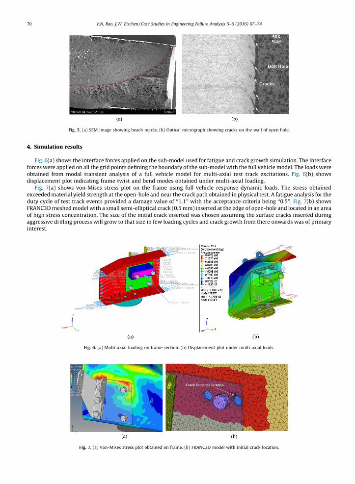
Fig. 4 shows primary crack initiations originated at the edge of the bolt hole and the secondary crack initiations originatedon the inner surface of the frame adjacent to the bolt hole. In Fig. 5(a), a low magnification SEM image shows the beach marks(above the red dashed lines) indicative of a fatigue crack growth mechanism. Fig. 5(b) shows higher magnification opticalmicrograph image of the cracks on the bolt–hole wall which resulted from the aggressive hole drilling process.
A chemical analysis was performed on the frame section using an Optical Emission Spectrometer (OES). The chemicalcomposition of frame section was found to be consistent with the test requirement. The base metal hardness of the framesection was found to be 32 HRC in rockwell hardness, which was in the reasonable hardness range for quenched andtempered low carbon/manganese/boron steel.
Fig. 1. Full vehicle endurance test events.
V.N. Rao, J.W. Eischen / Case Studies in Engineering Failure Analysis 5–6 (2016) 67–7468
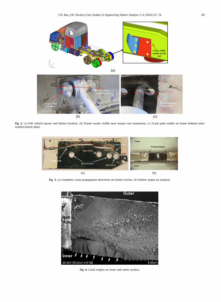
Fig. 2. (a) Full vehicle layout and failure location. (b) Frame cracks visible near torque rod connection. (c) Crack path visible on frame behind outer
reinforcement plate.
Fig. 3. (a) Complete crack propagation directions on frame section. (b) Failure origin on analysis.
Fig. 4. Crack origins on inner and outer surface.
V.N. Rao, J.W. Eischen / Case Studies in Engineering Failure Analysis 5–6 (2016) 67–74 69
4. Simulation results
Fig. 6(a) shows the interface forces applied on the sub-model used for fatigue and crack growth simulation. The interfaceforces were applied on all the grid points defining the boundary of the sub-model with the full vehicle model. The loads wereobtained from modal transient analysis of a full vehicle model for multi-axial test track excitations. Fig. 6(b) showsdisplacement plot indicating frame twist and bend modes obtained under multi-axial loading.
Fig. 7(a) shows von-Mises stress plot on the frame using full vehicle response dynamic loads. The stress obtainedexceeded material yield strength at the open-hole and near the crack path obtained in physical test. A fatigue analysis for theduty cycle of test track events provided a damage value of ‘‘1.1’’ with the acceptance criteria being ‘‘0.5’’. Fig. 7(b) showsFRANC3D meshed model with a small semi-elliptical crack (0.5 mm) inserted at the edge of open-hole and located in an areaof high stress concentration. The size of the initial crack inserted was chosen assuming the surface cracks inserted duringaggressive drilling process will grow to that size in few loading cycles and crack growth from there onwards was of primaryinterest.
Fig. 5. (a) SEM image showing beach marks. (b) Optical micrograph showing cracks on the wall of open hole.
Fig. 6. (a) Multi-axial loading on frame section. (b) Displacement plot under multi-axial loads.
Fig. 7. (a) Von-Mises stress plot obtained on frame. (b) FRANC3D model with initial crack location.
V.N. Rao, J.W. Eischen / Case Studies in Engineering Failure Analysis 5–6 (2016) 67–7470

In Fig. 8, crack growth history is shown where each step requires computing stress intensity factors (SIF) after growing thecrack in FRANC3D and using NASTRAN solver for finite element analysis. The loads used for crack growth simulation werefrom full vehicle response dynamic loads and the 3D crack growth was chosen to be for constant amplitude fatigue type. Thecrack kink angle was determined using the strain energy release rate method. The well-known ‘‘Paris law’’ was used forfatigue growth rate model and the coefficients for Paris law were obtained from the frame supplier [10] (coefficientC = 6 � 10�8, exponent m = 2.26, Kthreshold = 316.2 MPa Hmm). Stress intensity factors (SIF) were computed using the‘‘Interaction Integral’’ (M-Integral) method and include effects of crack face contact and crack pressure.
5. Discussion
Based on the visual inspection and metallographic examination it was confirmed that the curvilinear crack growth on theframe rail was a fatigue failure and crack initiations was due to a poor quality drilled hole on the frame. The crack pathobtained was influenced by mixed-mode stress intensity factors. The simulation results obtained were used to understandthe root cause of failure and can be used to recommend design modifications to prevent such extensive fatigue failure ofheavy duty truck frame.
The damaging loads identified were primarily from vehicle turning events which results in rear drive axle torque rodpushing the torque rod bracket into the web of frame section, causing an out-of-plane bending as shown in Fig. 9(a). This outof plane bending loads causes any cracks present on the outer frame surface to open and grow under Mode I type crackgrowth behavior. Fig. 9(b) shows crack opening (scaled 10 times) at step 17 under out-of-plane bending loads on frame.
Fig. 8. Crack growth steps showing crack extension on frame.
Fig. 9. (a) Out-of-plane bending of frame during turning event. (b) Crack opening under frame bending loads.
V.N. Rao, J.W. Eischen / Case Studies in Engineering Failure Analysis 5–6 (2016) 67–74 71

Fig. 10 shows comparison of crack path obtained between physical test and full vehicle response based 3D crack growthsimulation result. It can be seen that the curvilinear mixed-mode crack path simulated has good agreement with physicaltest result. The primary crack path was observed to follow high stress zone as identified in simulation result, the secondarycrack paths were not considered during simulation.
5.1. Sensitivity analysis of frame open-hole location
The objective of this sensitivity study was to determine the effect of moving the open-hole on frame that had been drilledclose to an existing bolt (high stress area) further from its initial location in order to determine if maintaining a certaindistance from the high stress area will be identified to prevent fatigue failure. In Fig. 11, description of design iterationsperformed for sensitivity study is shown. The frame open-hole was moved along ‘‘X’’ direction in multiple increments andthe distribution of stress concentration near open-hole was studied. It is to be noted that frame holes are often drilled tomount brackets and for routing of hydraulics and electrical wires. This study helps identify no-drill zone based on both safelife and fracture mechanics perspective.
Fig. 10. Frame crack during physical test compared with simulation result obtained using full vehicle response based 3D crack growth process.
Fig. 11. Location of frame open-hole moved along ‘‘X’’ direction for sensitivity study.
V.N. Rao, J.W. Eischen / Case Studies in Engineering Failure Analysis 5–6 (2016) 67–7472

The endurance strength (1E6 cycles) of the frame was found to be 2403 m (microns) [10] corresponding to a stress of478 MPa. From the stress based design the allowable open-hole location was found to be around 45 mm from its initial location,as shown in Fig. 12(a). However the fracture mechanics approach was necessary to ensure a reliable location for frame holes.
The fracture mechanics approach involves inserting small semi-elliptical surface crack at different open-hole locationsand extracting maximum stress intensity factors along crack fronts. It was observed KI drops linearly with distance andapproaches Kthreshold at a distance of around 75 mm from its initial location. In Fig. 12(b), KI remains above Kthreshold at 45 mmand an aggressive open-hole would still lead to crack propagation under fatigue loading at that distance. This study providesa comparative view of two design approaches and helps identify a no drill zone on frame rails near high stress areas.
6. Conclusions
Based on the experimental observations and simulation results, it can be concluded that an aggressively drilled open holecreated small crack initiations in a high stress-state location of the frame, which resulted in extensive curvilinear crackgrowth under dynamic loads of the vehicle. The FRANC3D crack propagation tool combined with NASTRAN finite elementsolver predicted crack path similar to physical test failure and provided a good correlation for cycles to failure. A sensitivitystudy was done to identify safe zone for open holes and would help specify restrictions on frame hole drilling. The presentwork provides successful methodology applied to failure analysis of frame rail cracks in heavy duty trucks, which may also beapplied for other engineering failure analysis problems.
Acknowledgements
The research presented here was partially carried out at the Advanced Calculations group of Chassis Vehicle Dynamicsand Engineering (CVDE) section of Volvo Group North America, Greensboro, North Carolina, USA. The authors would like tothank Dr. Omar Ibrahim at Process Optimization Corporation for providing support and license for FRANC3D program in thisresearch.
References
[1] Sih GC. Strain-energy-density factor applied to mixed mode crack problems. Int J Fract 1974;10(September (3)).[2] Chao Y-J, Zhu X-K. A simple theory for describing the transition between tensile and shear mechanisms in mode I, II, III and mixed-mode fracture.
Mixed-mode Crack Behav ASTM STP 1999;1359:41–57.
Fig. 12. (a) Safe life approach and (b) damage tolerant approach results for sensitivity study.
V.N. Rao, J.W. Eischen / Case Studies in Engineering Failure Analysis 5–6 (2016) 67–74 73
[3] Yates JR, Zanganeh M, Tomlinson RA, Brown MW, Diaz Garrido FA. Crack paths under mixed mode loading. Eng Fract Mech 2008;75:319–30.[4] Davis BR, Wawrzynek PA, Ingraffea AR. Simulation of arbitrary mixed-mode crack growth using an energy-based approach.In: Conference proceedings
of the society for experimental mechanics series. Fract Fatigue Fail Damage Evol 2015;5:1–9.[5] Seifi R, Eshraghi M. Effects of mixed-mode overloading on the mixed-mode I+II fatigue crack growth. Arch Appl Mech 2013;83(July (7)):987–1000.[6] Seifi R, Omidvar N. Fatigue crack growth under mixed mode I+III loading. Mar Struct 2013;34:1–15.[7] Miller EE, Sutton MA, Deng X, Watts H, Reynolds AP, Ke X, et al. Experimental and predicted crack paths for Al-2024-T351 under mixed-mode I/II
fatigue.In: Conference proceedings of the society for experimental mechanics series. Fract Fatigue Fail Damage Evol 2015;5:11–20.[8] Deng X, Ke X, Sutton MA, Watts HS, Schreier HW. Curvilinear fatigue crack growth under out-of-phase loading conditions.In: Conference proceedings
of the society for experimental mechanics series. Fract Fatigue Fail Damage Evol 2015;5:27–34.[9] Fremy F, Pommier S, Poncelet M, Raka B, Galenne E, Courtin S, et al. Load path effect on fatigue crack propagation in I+II+III mixed mode conditions –
Part 1: Experimental investigations. Int J Fatigue 2014;62:104–12.[10] Fleming S. Fatigue crack growth for typical CV siderail hole-making processes applied to heat-treated steel (MET1123) and ultra-high strength low
alloy steel (120XF). SAE International; 2009, 2009-01-2863.
V.N. Rao, J.W. Eischen / Case Studies in Engineering Failure Analysis 5–6 (2016) 67–7474