Embed Size (px)
Citation preview
N 7 3 - 1 9 8 2 7 \MSC 04423-1
MDC E0674
CASE FILECOPY FINAL REPORT
SPACE SHUTTLE
AUXILIARY PROPULSION SYSTEM
DESIGN STUDY
EXECUTIVE SUMMARY
/VfCDO/V/Vtl_l- DOUGLAS ASTRONAUTICS CO/VTFVt/VV -EAST
/VTCOO/V/VHI.L DOUGLAS
COHPOftATIOM
https://ntrs.nasa.gov/search.jsp?R=19730011100 2018-06-19T02:52:19+00:00Z

MSC (M23-1
COPY NO.
SPACE SHUTTLE
AUXILIARY PROPULSION SYSTEM
DESIGN STUDY
EXECUTIVE SUMMARY
29 DECEMBER 1972 REPORT MDC E0674
FINAL REPORT
Prepared by: PJ. KellyT.F. Schweickert
Approved by: L.F. KohrsManager, Propulsion
Contract No. NAS 9-12013
MCDONNELL. DOUGLAS ASTRONAUTICS COMPANY - EAST
Saint Louis. Missouri63166 (314) 232-0232
MCDONNELL DOUGLAS
CORPORATION

APS STUDY MDC E0674Executive Summary 29 December 1972
ABSTRACT
This report summarizes the effort conducted in support of the SpaceShuttle Auxiliary Propulsion System Design Study and defines the pre-liminary design of the final selected subsystems. The study was per-formed for the National Aeronautics and Space Administration underContract NAS 9-12013.
/VffCDOJVMELL DOUGLAS ASTRONAUTICS COMPANY ' EAST

APS STUDY MDC E0674
Executive Summary 29 December 1972
TABLE OF CONTENTS
Section Page
1. Introduction .. 1-1
2. Study Approach 2-1
3. Oxygen/Hydrogen Studies 3-1
3.1 Requirements Definition - Phase A 3-13.2 Candidate RCS Comparisons - Phase B . 3-13.3 RCS/OMS Integration Study Phase C 3-53.4 Special RCS Studies - Phase D ...3-5
4. Earth Storable Propellent Studies 4-14.1 Requirements 4-24.2 Concepts Description 4-24.3 Design Definition 4-74.4 Concepts Comparison 4-174.5 Reusability Effects 4-22
5. Conclusions 5-1
6. References 6-1
EFFECTIVE PAGES
Title Page
ii and iii
1-1 and 1-2
2-1 through 2-4
3-1 through 3-9
4-1 through 4-25
5-1 through 5-3
6-1
MCDONNELL. DOUGLAS ASTRONAUTICS COMPANY • EAST

APS STUDYExecutive Summary
MDC E067429 December 1972
1. INTRODUCTION
To provide the technology base necessaryfor design of the Space Shuttle, NASA hassponsored a number of technology programsrelated to Auxiliary Propulsion Systems(APS). Among such programs has been aseries of design studies intended to providethe system design data necessary for selectionof preferred system concepts, and to delineaterequirements for complementing componentdesign and test programs. The first of thesesystem study programs considered a broadspectrum of system concepts but, because ofhigh vehicle impulse requirements coupledwith safety, reuse, and logistics considera-tions, only cryogenic oxygen and hydrogenwere considered as a propellant combination.Additionally, unknowns in thruster pulsemode ignition and concern over thedistribution of cryogenic liquids served toeliminate liquid-liquid feed systems from thelist of candidate concepts. Therefore, onlysystems which delivered propellants to thethrusters in a gaseous state were consideredfor the Reaction Control System (RCS). Theresults of these initial studies, reported inReferences A through D, indicated thatamong the many options for design of agaseous oxygen/hydrogen system, an ap-proach using heat exchangers to thermallycondition the propellants and turbopumps toprovide system operating pressure would bestsatisfy requirements for a fully reusableSpace Shuttle. These initial studies focusedattention on this general system type but didnot examine in depth several viableapproaches for turbopump system design andcontrol. To fill this need, NASA contractedwith McDonnell Douglas Astronautics Com-pany-East (MDAC-E) in July 1971 for addi-tional study of Space Shuttle AuxiliaryPropulsion Systems. This contract (NAS9-12013), titled "Space Shuttle AuxiliaryPropulsion System Design Study," was underthe technical direction of Mr. Darrell Ken-drick, Propulsion and Power Division,Manned Spacecraft Center, Houston, Texas.
The objective of this study was to develop
design and programmatic data for candidateSpace Shuttle RCS in sufficient detail that avalid selection could later be made betweenthe various concepts. As originally defined,the study considered only oxygen and hydro-gen propellants. The program was dividedinto the five phases listed below:
1. Phase A - Requirements Definition2. Phase B - Candidate RCS Concept
Comparisons3. Phase C - RCS/OMS Integration4. Phase D - Special RCS Studies5. Phase E - System Dynamic Performance
AnalysisPhase A defined all design and operating
requirements for the APS. The result of thisphase showed that requirements for thebooster and orbiter stages were sufficientlysimilar to allow concentration of all design ef-fort on the orbiter stage, with the resultsbeing applicable to the fly-back-type boosterstage as well. These results are documented inReference E. In Phase B, very detailed designand control analysis for the three mostattractive oxygen/hydrogen RCS conceptswere conducted. Reference F documents thePhase B results. Phase C evaluated thepotential for integration of the RCS with theOrbit Maneuvering System (OMS). ReferenceG provides documentation of the Phase Coxygen/hydrogen efforts. In Phase D twoalternates to gaseous oxygen/hydrogenturbopump RCS were investigated. The re-sults of this phase are documented in Refer-ence H.
According to the initial program plan,Phase E was to analyze the oxygen/hydrogenRCS dynamic response characteristics. How-ever, concurrent with this study, vehiclestudies showed that smaller Shuttle orbiterswith external, expendable main engine tank-age would provide a more cost effectiveapproach than the larger vehicle used togenerate baseline requirements in Phase A.This change in vehicle design resulted in asignificant reduction in the APS impulse re-quirements. This effect, together with a
1-1
DOUGLAS ASTRONAUTICS COMPANY • E AST

APS STUDYExecutive Summary
companion Shuttle program decision to allowscheduled system refurbishment, allowedconsideration of earth storable propellantsystems for auxiliary propulsion. Thus, inNovember 1971, NASA issued a contractchange order to consider monopropellant andbipropellant storable systems. This resultedin a redirection of Phases C and E of thestudy. Phase C was expanded to include eval-uation of candidate storable propellant RCS,with varying degrees of integration with theOMS and the Auxiliary Power Unit (APU).In the redirected Phase E, performance of themost promising storable RCS/OMS/APUoptions was analyzed. Reference I documentsthe results of the storable propellant Phase Cand E efforts.
Results from the oxygen/hydrogen portionof the study indicated that, for the largerorbiter with internal main tanks, maximumpayload weight is obtained with a liquid-liquid oxygen/hydrogen RCS installedintegrally within the vehicle. For the smaller
MDC E067429 December 1972
orbiter with external main tanks, installationof the oxygen/hydrogen RCS is practical, butsufficient volume is not available for anoxygen/hydrogen OMS. Thus, the OMS mustutilize higher density storable propellants.The high costs associated with the develop-ment of oxygen/hydrogen technology werenot considered justifiable without applicationto both the RCS and OMS. Therefore, the ox-ygen/hydrogen propellants were eliminatedfrom further consideration after the orbiterdesign change. Consequently, althoughoriginally intended to study oxygen/hydro-gen systems, the main portion of the study ef-fort concentrated on earth storable propel-lants.
This report summarizes the tasks con-ducted in Phases A through E of theAuxiliary Propulsion System Design Studyand defines in summary form the final config-urations for the alternate propellant config-urations, with primary emphasis on earthstorable propellants.
1-2
MCDONNELL. DOUGLAS ASTRONAUTICS COMPANY • EAST

APS STUDYExecutive Summary
NIDC E067429 December 1972
2. STUDY APPROACH
The Space Shuttle Auxiliary PropulsionSystem Design Study was conducted in fivephases. Reference J provides a detailedprogram plan for the complete study, and de-fines the task objectives and their relation-ship to the overall study. The tasks for theoxygen/hydrogen and earth storable propel-lants studies are shown in Figure 2-1 in flowchart form. Figure 2-2 defines the programschedule.
Phases A, B, C (RCS/OMS Integration),and D considered oxygen and hydrogenpropellants. In Phase A, vehicle requirementswere defined. Specifically, engine thrustlevels, locations, and number of engines wereestablished. Thruster minimum impulse-bitwas determined, based on historic engine dataand, in conjunction with deadband require-ments, used to establish total impulse forlimit cycle operation. Combined withmaneuver requirements, this information wasused to establish total impulse requirementsfor the oxygen/hydrogen studies.
Phase B was a continuation of the initialoxygen/hydrogen studies which had identi-fied the following three high value concepts:(1) a series-upstream turbine concept whichused the combustion products from a singlegas generator to first power the turbopumpand then thermally condition the propellants,(2) a series-downstream turbine concept inwhich the order of gas generator exhaust flowthrough the heat exchanger and turbine wasreversed from that above and, (3) a parallelRCS concept which employed separate gasgenerators to power the turbopump and heatexchanger. In Phase B, detailed analyses wereperformed to define preferred controls andoptimum system design points for the threeRCS concepts. Additionally, steady-state andtransient operational characteristics and theeffects of system malfunctions were evalu-ated. Finally, the concepts were compared onthe basis of pertinent selection criteria.
The Phase C RCS/OMS integration effortevaluated the integration potential betweenthe oxygen/hydrogen RCS and the Orbit
Maneuvering System (OMS). Integration op-tions ranged from a fully integrated system toa separate system in which only propellantstorage was common. Preferred methods wereselected and design points were developed fortwo fully integrated systems, one partiallyintegrated system, and one separate system.
Phase D explored the potential of the twoalternate, oxygen/hydrogen RCS conceptslisted below:
(1) Gaseous oxygen/hydrogen systems,with conditioners similar to those of thePhase B candidates, but using alternatemeans of providing system pressure,e.g., electric or hydraulic motor drivenpumps or pneumatic bellows pumps.
(2) Liquid oxygen/hydrogen systems,which eliminated conditioning equip-ment entirely and delivered the propel-lants to the engines in a liquid ratherthan a gaseous state.
For these two system concepts, the opera-tional characteristics of electric and hydraulicmotor driven pumps were evaluated to definesystem performance. Additionally, a detailedthermal analysis of the liquid system wasperformed to determine the feasibility of thisconcept.
In the Phase C earth storable propellantsstudy, effort focused on providing sufficientcomparative data on alternate storable pro-pellant concepts to allow selection of the bestapproaches for the Phase E System Perform-ance Analysis. RCS/OMS/APU integrationoptions were evaluated to determine theproper compromise between performance andoperating requirements. Both monopropellant(hydrazine) and bipropellant (nitrogen tetrox-ide/monomethylhydrazine) concepts wereconsidered. Preliminary baseline designs, re-flecting various levels of system integration,served as reference points for detailed designand installation studies and for concurrentstudies of APU implementation and advancedpressurization and tankage concepts. Fromthese studies, design concepts were updatedand six systems were selected for the Phase E
2-1
DOUGLAS ASTftOMAvrics COMPANY- EAST

APS STUDYExecutive Summary
MDC E067429 December 1972
3 =
SE
SSiS ^ Sl£a r\lii1/81 =3S5-
!Ki
te R
CS
Con
cept
Co
.i
•s•gu
§6 152 °-
2
sEi
'
i
•
e
'
i'
i
^
t
SE
LEC
T IT
ST
EI
t
t
•
i \s i? s. a
•
•! 8u S
t
!
IOLE
RA
HC
E D
AT
A
J
-£,
Def
initi
on (
$2
/\i.i
.1
li
t
SYST
EN T
EST
GU
IDE
LIN
ES
k
r~
PE
RF
OR
I V
EH
ICLE
IIT
TE
GR
AT
IOIt
iTU
OlE
i
i
li
tiis»
t"»
1 -
if
a!
t=
oc<:o
DCOcoLUQ
co
COQ_
oc.=3O
2-2
AfCOO/V/Vf I.L DOUGLAS ASTRONAUTICS COMPANY • EAST

APS STUDYExecutive Summary
MDC E067429 December 1972
c
a
c
GO
-AH
EAD
o:
cE
3
C
O
1 ^5 ;
1 iO i
£' i5 ;
_L 1*
£
£S
REQ
UIR
EMEN
TS D
EFI
NIT
ION
RE
VIE
* r I
NFO
RM
AL'
INTE
RIM
SYS
TEM
S D
EFI
NIT
ION
REV
IEW
'IN
FOR
MA
L'
RCS
QMS
'APti
SYST
EMS
PREL
IMIN
ARY
DEFIN
ITION
REV
IEW .I
NFOR
MAL-
IO, •
SYST
EM D
EFIN
ITION
REV
IEW .I
NFOR
MAL.
FIN
AL
DES
IGN
RE
VIE
* 'IN
FOR
MA
L'
—
FIN
AL
BR
IEFI
NG
<FO
RM
AL>
PRO
GR
AM C
OM
PLET
ION
Xss
--
3
•
THS
AFT
ER
GO
-AH
EA
*
•
£
ss
pg
11
i!
1
J
DE
FIN
E R
CS
'O
W R
EQU
IREM
ENTS
RE
VIE
I C
OM
PON
ENT
MO
DEL
SD
EV
ELO
P C
OM
PON
ENT
TOLE
RA
NC
E D
AT
A ..
.PE
RFO
RM
VE
HIC
LE I
NTE
GR
ATI
ON
STU
DIE
SE
STA
BLI
SH
PR
OP
ELL
AN
T TA
NK
AG
E P
RE
SS
UR
IZA
TIO
N M
OD
EL ....
CO
HD
UC
1 P
RE
LIM
HA
RY
SY
SliM
S A
NAL
YSIS
M
SC
RE
EN
SYS
TEM
CO
NTR
OL
POIN
TSS
Fl E
CT
CO
NTR
OL
CO
MC
FPTS
^
i££
*
is^ 2 s :
-
1a
*
u
§
||1
O
1
u
1
J
1saB a
i!• i
iiu. u
5 = = ;
.
IIII •9 1
.1
III
ll
I'
i i £ 5§*"l 5 ss.,
Illll 1 i Isll
i i 1
j j f f
[i|i|iIfjlfl• ^ ..j * — <» •— •- 1~ •— •—i lsSSSA O > O O OiJ O UJ t-> CJ (_>
0 _ » < - 1 V ^ W I ' ~ 0 «
(
III
_
. — i
CO
ND
UC
T S
HU
TTLE
REU
SE S
TUD
IES
CO
ND
UC
T P
RO
PE
LLA
NT
STO
RA
GE
. A
CQ
UIS
ITIO
N A
ND
STO
RAG
E A
NA
LYS
ISD
EFI
NE
CO
MPO
NENT
MO
DEL
SE
VA
LUA
TE
LIN
E I
NS
ULA
TIO
N 'C
OO
LIN
G C
ON
CEP
TSE
STA
BLI
SH
PR
ELI
MIN
AR
Y S
YS
TEM
DES
IGN
S
FIN
ALI
ZE
SYS
TEM
DES
IGN
AN
D R
EVIE
W S
YSTE
M T
ECH
NO
LOG
Y
DE
FIN
E S
YS
TEM
REU
SE.
MA
INTE
NA
NC
E S
AFE
TY A
ND
OPE
RAT
ION
AL C
RIT
ER
IAU
PD
ATE
AN
D D
EFI
NE
SYS
TFM
AN
ALY
SIS
..
i*-£
EgS<
3
1UJ
i10
UJ
a
H 5 3 3 2 5 3 3 23
^^
ID O
XY
GE
N/H
YD
RO
GE
N R
CS
'OKS
IN
TEG
RA
TIO
N S
TUO
Y'?
) EA
RTH
STO
RA
BLE
PR
OP
ELL
AN
TS S
TUO
Y
FIG
UR
E 2-
2 M
ASTE
R
SCH
EDU
LE
2-3
MCDONNELL. DOUGLAS ASTRONAUTICS COMPANY - EAST

APS STUDY MDC E0674
Executive Summary 29 December 1972
final performance analysis. In this phase, Propulsion Design Study. The following sec-system designs and performance were refined, tions provide a summary of the alternateand system reuse, maintenance, safety, and oxygen/hydrogen and earth storable systems,operational criteria were established. Also presented is a description of the designs
This report summarizes the tasks conduct- selected, their operation, and the rationaleed in Phases A through E of the Auxiliary behind their selection.
2-4
MCDONNELL DOUGLAS ASTRONAUTICS COMfAtW - EAST

APS STUDYExecutive Summary
MDC E067429 December 1972
3. OXYGEN/HYDROGEN STUDIES
The oxygen/hydrogen effort performed inthis study was divided into three areas: (1) afurther evaluation of turbopump RCS config-urations initially studied under Contract NAS8-26248, (2) an assessment of the integrationpotential of the RCS and QMS, and (3) aninvestigation of RCS concepts utilizing powersources other than turbopumps. The sectionsthat follow provide a summary of the resultsof these investigations.
3.1 Requirements Definition - Phase A -RCS thrust level and total impulse were es-tablished for the vehicle configuration, designcharacteristics, and acceleration requirementsdefined in the Space Shuttle Vehicle Descrip-tion and Requirements Document(SSVDRD).The distinguishing feature of this orbiter wasthat the main engine propellant tanks wereinternal to the vehicle, resulting in a largeorbiter stage.
A detailed study was conducted to defineAPS thrust level, total impulse and number ofthrusters. Options available within the con-straints imposed by the vehicle accelerationrequirements and vehicle configuration werecompared to establish the installation andthruster characteristics which would provideminimum RCS weight. A thrust level of 1150Ibf was selected for the RCS thrusters. At thislevel, 33 RCS thrusters were required. It wasalso required that the system be capable ofsustaining the firing of five thrusters (5750 Ibfequivalent thrust). This corresponds to theuse of four thrusters for translation and theequivalent of one additional thruster for ve-hicle attitude control during the maneuver.The total RCS impulse, including bothattitude control and vernier translation man-euvers of less than 20 ft/sec was 2.23 millionIbf-sec. Axial translation maneuvers in excessof 20 ft/sec were allocated to the OrbitManeuvering System (OMS). Impulse re-quirements for three typical missions were de-fined. Figure 3-1 summarizes the RCS andOMS design requirements.
Several general requirements which apply
to both RCS and OMS design include minimalmaintenance with ease of component removaland replacement, a minimum service life of100 mission cycles over a ten year period withcost effective refurbishment, and seven daysof self-sustaining life for each mission.Additionally, the RCS and OMS must pro-vide control for crew safety after the failure ofany two critical components, except in theevent of an abort caused by a main enginefailure. In this case, the OMS must only oper-ate after a single failure since the main engineloss constitutes the first system failure.
RCS NUMBER OF THRUSTERSTHRUSTER THRUST (LB)
NUMBER OF CONDITIONERS
SYSTEM THRUST (LB)
TOTAL IMPULSE (LB-SEC)
RESUPPLY
EASTERLY LAUNCHSOUTH POLAR
OMS NUMBER OF ENGINESENGINE THRUST (LB)
SYSTEM THRUST (LB)
TOTAL IMPULSE (LB-SEC)
RESUPPLY
EASTERLY LAUNCH
SOUTH POLAR
ORBITER
331,150
35,750
2.23 x 10⁶
2.23 x 10⁶
2.15 x 10⁶
DESIGNED FOR
ORBITALOPERATIONS
10.34 x 10⁶
3.72 x 10⁶
12.87 x 10⁶
BOOSTER
241,150
49,200
500,000
DESIGNED FORABORT
3
12,00024,000
FIGURE 3-1 RCS/OMS DESIGNREQUIREMENTS
3.2 Candidate RCS Comparisons - Phase BThree alternate gaseous oxygen/hydrogenRCS configurations were considered in thisstudy phase. These differ in the arrangementof the gas,'generators, turbopumps, and pro-pellant conditioners, as shown in Figure 3-2.The first concept places the turbine upstreamfrom the conditioner in the gas generator ex-haust flow. The second concept reverses theorder of the turbine and conditioner. The thirdconcept uses two parallel gas generators, onefeeding the turbine and one feeding the con-ditioner.
3-1
/tfCDOJV/VE'f-f. DOUGLAS ASTRONAUTICS COMfANY - EAST

APS STUDYExecutive Summary
MDC E067429 December 1972
SYSTEMWEIGHT, LBN1TOTAL IMPULSE, LBF-SECSPECIFIC IMPULSE, SECMIXTURE RATIO
THRUSTERTHRUST LEVEL, LBFSPECIFIC IMPULSE, SECMIXTURE RATIOCHAMBER PRESSURE, LBF 'IN2A
GAS GENERATOR
COMBUSTION TEMPERATURE, °RCHAMBER PRESSURE, LBF 'IN2AMIXTURE RATIO
HEAT EXCHANGERHOT SIDE EXIT TEMPERATURE, °RCOLD SIDE EXIT TEMPERATURE, °R
TURBOPUMPFLOW RATE, LBM/SECDISCHARGE PRESSURE, LBF 1N2ATURBINE PRESSURE RATIO
ACCUMULATORSNUMBER OF CYCLESVOLUME, FT3
MINIMUM PRESSURE, LBF 'IN2ASWITCH PRESSURE, LBF/IN2AMAXIMUM PRESSURE, LBF/IN2A
SERIES TURBINEUPSTREAM
~^T=^1 /n*-«_-w — LJ
10,2322.23M367
3.12
1,150428
4300
H2 02
2,000 2,000250 250
1 1
800 800263 503
3.80 11.861.550 1,7502.60 2.10
50 5042.5 14.1571 571665 666
1,310 1,555
SERIES TURBINEDOWNSTREAM
«— *»—(7~\
U!r10,348
2.23M3663.11
1,150428
4300
H2 02
2,000 2,000250 250
1 1
930 870253 506
3.82 11.881,330 1,8508.00 2.90
50 5044.8 14.9571 571665 666
1,275 1,545
PARALLEL FLOW
^H ^H
^M5r10,907
2.23M3482.91
1,150428
4300
H2 02
2,000 2,000250 250
1 1
800 800245 466
4.23 12.301,190 1,57016.7 16.7
50 5049.5 15.1571 571660 661
1,200 1,450
FIGURE 3-2 RCS DESIGN SUMMARY
As an example of system operation, con-sider the turbine upstream concept, shownschematically in Figure 3-3. During systemoperation, propellants from the cryogenicstorage tanks are pumped to high pressureusing turbopumps, thermally conditioned tosuperheated vapors in heat exchangers, andthen stored in accumulators. Gaseous propel-lants are supplied to the film cooled thrusterassemblies through pressure regulators. Theenergy for propellant pressure and tempera-ture conditioning is supplied by combustion
products from bipropellant gas generators.Oxygen and hydrogen propellants are sup-plied to the gas generators from the accum-ulators. The accumulators operate in ablowdown mode with accumulator pressuredecaying from a maximum value to aswitching value. At the switching value,accumulator resupply is initiated. The gasgenerators are ignited, providing energy topower the turbopump and heat exchanger.Accumulator pressure continues to decay to aminimum value during the conditioner
3-2
/VffCOO/V/VEt-f- DOUGLAS ASTRONAUTICS COMfANY - EAST

APS STUDYExecutive Summary
assembly start transient, and then begins toincrease as steady state resupply flowrate isachieved. Resupply flow is maintained by theconditioner assembly until accumulatorpressure rebuilds to its maximum value,whereupon propellant flow to the gas gen-erators is terminated. The accumulator
LH
MDC E067429 December 1972
blowdown/recharge cycle is repeated asmany times as necessary to satisfy missiontotal impulse requirements. Although theaccumulators operate over a wide pressurerange, propellant flow is regulated to constantsupply pressure downstream of the accumu-lators, maintaining a constant inlet pressureto the thrusters and gas generators.
VENT
GO,
GASGENERATOR
FIGURE 3-3 BASIC RCS CONCEPT
Design points for the three systems are de-fined in Figure 3-2. As shown, the two seriesconcepts are nearly identical in systemperformance. A power balance of these sys-tems requires high hot side heat exchangerflow rate, and at this flow rate, pump powerrequirements are satisfied with low turbinepressure ratios. As a result, vent pressuresare relatively high in the two series concepts.However, in the parallel RCS, low turbineflow rates and corresponding high turbinepressure ratios are required to efficiently uti-lize the available thermal energy from the gasgenerator combustion products. Even withthe high turbine pressure ratios, the enthalpyof the exhaust gas is high for the parallelRCS, resulting in a lower system specific im-pulse.
All three RCS concepts can be controlledwithin tight operational limits. Figure 3-4summarizes the optional control concepts forthe three candidate configurations. Gas gen-erator combustion temperature control wasnecessary to avoid excessive turbine/heat
exchanger gas inlet temperatures, and wasbest achieved through modulation of the gasgenerator oxygen valve. This controlprovided a large system weight reduction andreduced the operating bands of other criticalsystem parameters, such as conditioned pro-pellant temperature and pump dischargepressure (flow rate). Control of hydrogen con-ditioned temperature in the two seriesconcepts and both hydrogen and oxygenconditioned temperature in the parallel RCSwas selected to provide additional systemweight reductions. This control was bestachieved by modulating the amount of heatexchanger cold side bypass flow. Thisbypass was required in the series-upstreamturbine RCS (hydrogen conditioner) and par-allel RCS (both hydrogen and oxygen condi-tioners) to preclude r^O condensation andicing on the hot side tube walls. It was in-corporated in the series-downstream turbineRCS (hydrogen conditioner) for the purposeof conditioned temperature control. The final
3-3
MCDONNELL. DOUGLAS ASTRONAUTICS COM fANY • EAST

APS STUDYExecutive Summary
system control provided for modulation of thegas generator H2 valve in response to pumpdischarge pressure. This control providedonly a modest system weight benefit, but itprovided excellent control of heat exchangercold side inlet conditions and turbopump
MDC E067429 December 1972
power, minimizing the development risk as-sociated with these assemblies. Heat ex-changer cold side flow instability has beenencountered in previous development pro-grams, and its potential for occurrence is re-duced with tight control of inlet conditions.
Series RCS(Turbine Upstream)
Series RCS(Turbine Downstream)
Parallel RCS
ACTIVE CONTROL POINT
1. GAS GENERATOROXYGEN VALVE
2. GAS GENERATORHYDROGEN VALVE
3. HEAT EXCHANGER COLDSIDE BYPASS VALVE(H2 ONLY FORSERIES CONCEPTS)
INTERMEDIATE CONTROL FUNCTIONS CONTROLLED PARAMETER
( GAS GENERATOR"V COMBUSTION TEMPERATURE
TURBINE INLET TEMPERATURE,FLOW RATE, PRESSURE RATIOAND POWER
HEAT EXCHANGER COLDSIDE FLOW RATE
PUMP DISCHARGEPRESSURE
CONDITIONEDPROPELLANTTEMPERATURE
FIGURE 3-4 CONTROL POINT SUMMARY
The three RCS concepts were compared onthe basis of weight, complexity, flexibility,reliability, and technology considerations.The two series concepts rated even, rankinghigher overall than the parallel RCS. A choicebetween the two series concepts depends onthe Shuttle development philosophy. Theupstream turbine RCS affords the lowestweight and volume, but the system require-ments must be firmly established at the pro-gram outset. Attempts to improve the system
performance at a later date for a second gen-eration vehicle would lead to a complete con-ditioner redesign due to the turbine inlet tem-perature restrictions. The series-downstreamturbine RCS can be uprated by increasing gasgenerator combustion temperature andreconfiguring only the heat exchanger for thecorrespondingly higher hot side inlet temper-ature.
Several technology concerns were identifiedduring the course of the study. Among these
3-4
MCDO/VtVELL. DOUGLAS ASTRONAUTICS COMFANY - EAST

APS STUDYExecutive Summary
was the high conditioner cycle life require-ment of 5000 cycles (50 cycles per mission for100 missions) which is a significant extensionover the demonstrated life capabilities of cur-rent turbopump and heat exchanger designs.In addition, transient conditioner startupanalyses showed that turbopump shaft accel-erations on the order of 165,000-200,000RPM/sec can be expected. Since currentexperience with propellant-cooled bearings isapproximately 40,000 RPM/sec, pump bear-ing design must be regarded as a criticaltechnology area.
3.3 RCS/OMS Integration Study-Phase C-During this portion of the APS Design Study,all viable oxygen/hydrogen RCS/OMSintegration configurations were compared.The RCS baseline configuration for this studyphase was the parallel flow concept. The OMSuses liquid propellant engines fed from a pro-pellant storage assembly. The degree ofintegration varied from a fully integratedRCS/OMS with common turbomachinery,gas generators, and heat exchangers to a sep-arate system with common propellant tank-age only.
Preliminary screening resulted in theselection of four candidate concepts. Theselected configurations were two fullyintegrated systems, one partially integratedsystem, and a separate system. Fullyintegrated systems utilize common turbo-pumps to supply liquid propellants to theOMS engines, and gaseous propellants to theRCS thrusters via the heat exchangers andaccumulators. In the partially integrated sys-tem, the RCS and OMS are provided dedi-cated gas generators and turbopumps, whichare powered by oxygen and hydrogen propel-lants stored in common accumulators. In theseparate system, the propellant tankage is theonly RCS/OMS interface.
The fully integrated system is attractivedue to hardware commonality, However, as-sociated problems include OMS and RCSmixture ratio differences, RCS accumulatorresupply during OMS operation, and controlsfor propellant sequencing to the OMSengines. Mixture ratio differences were re-solved by using either an extra oxygen pump
MDC E067429 December 1972
for the OMS operation or by utilizing bileveloperating pumps. The remaining problemsare alleviated at reduced levels of integration.
Hardware commonality can be implement-ed in the partially integrated system by usinga common-design turbopump capable of bi-level operation. The bilevel turbopumps aredesigned for the OMS requirements andoperate off-design for the RCS. For both fullyand partially integrated systems, therecommended method of providing accum-ulator makeup propellant during OMSoperation is with a separate, small heat ex-changer/gas generator unit sized to conditiononly the accumulator makeup gas. Thisoption requires the development of anadditional component, but is the preferredapproach since it minimizes the number ofRCS conditioner cycles.
Separating the RCS and OMS completelyexcept for common propellant storage elimi-nates integration concerns, but does requiredifferent component designs. In the separateRCS/OMS, a staged combustion cycle OMSengine is recommended.
At the lower velocity requirements of theeasterly launch mission, the candidateRCS/OMS systems were all weight competi-tive. At the higher velocity increment (2000fps), the separate RCS/OMS system is themost attractive.
3.4 Special RCS Studies - Phase D - Twoalternatives to the turbopump gaseousoxygen/hydrogen systems discussed inSection 3.2 were evaluated. The first alterna-tive maintained the same basic approach asthe turbopump systems but used a highpressure liquid accumulator with a smallpump, thereby reducing pump power require-ments to levels where power sources otherthan hot gas turbines could be considered.Eliminating the turbopump avoided the tech-nology concerns associated with turbopumpbearing life in an environment requiring manyrapid startups per mission.
The second alternative also used a liquidaccumulator in conjunction with a low powerpump but considered distribution of oxygenand hydrogen as liquids to engines which hadthe capability for liquid propellant ignition.
3-5
MCDONNELL. DOUGLAS ASTRONAUTICS COMPANY - EAST

APS STUDYExecutive Summary
The "liquid" concept thereby eliminated theneed for gaseous accumulators and thermalconditioning equipment. The following para-graphs summarize the evaluation of these twoalternatives.
3.4.1 Alternate Gaseous Oxygen/HydrogenSystems - The gaseous systems evaluated asalternates to the turbopump systems are il-lustrated in Figure 3-5. The most funda-mental approach is a fully pressurized sys-tem. However, the weight penalty for fullpressurization of both the hydrogen and oxy-gen is severe (5000 Ibm).
The use of hydraulic or electric pumpsreduces the weight penalties that occur withfull pressurization. The number of pump
NIDC E067429 December 1972
cycles are minimized through the use of liquidaccumulators installed downstream of thepumps. Power for pump drive is provided bythe APU. The motor driven pump systemsare weight competitive with the referenceturbopump system. Their principal drawbackis their dependence on APU operation and theincreased number of APU starts incurred.Additionally, power requirements are inexcess of Other APU requirements and highercapacity APU's would be required.
System power requirements can be signifi-cantly reduced at constant system weightthrough the use of a hydraulic hybrid system.The oxygen side of this system is fully pres-surized, whereas a hydraulic motor pump -liquid accumulator configuration is employed
FULLY PRESSURIZED
ELECTRIC PUMP
I
or? :HYDRAULIC PUMP
FIGURE 3-5 GASEOUS 02/H2 CONCEPTS
3-6
MCDONNELL DOUGLAS ASTRONAUTICS COMPANY • EAST

APS STUDYExecutive Summary
for the hydrogen. The use of fully pressurizedoxygen results in some weight penalty, butsince oxygen accounts for less than 20% ofthe total propellant volume, this penalty issmall, and allows simplification of system de-sign and development.
Pump dependence on APU operation can becompletely eliminated with the use of bellowspumps. System controls are such that whenone liquid accumulator is depleted, itspressurant is vented and refill is providedunder the storage tank pressure head. The useof heated helium pressurant to minimize ventlosses results in a weight competitive system.
3.4.2 Liquid Oxygen/Hydrogen Systems -Liquid oxygen/hydrogen RCS concepts wereevaluated to determine the feasibility of dis-tributing liquid propellants to the engines.This approach would allow removal of the gasgenerators, propellant heat exchangers, andgaseous accumulators, as depicted in Figure3-6. The particular configuration illustrated isbut one of a generic series derived from thebasic turbopump RCS. In addition toadvantages in system simplicity, the liquidconcept offers a large system weightreduction by eliminating the heavy gaseousaccumulators and by avoiding gaseouspropellant conditioning losses.
APU
I
FIGURE 3-6 LIQUID - LIQUID CONCEPT
Liquid cryogenic systems were not con-sidered in previous studies due to concernsassociated with propellant heating in a large,relatively complex distribution system andbecause of concerns with engine pulse modeignition. Figure 3-7 illustrates these concerns.Although the ignition temperature limits are
MDC E067429 December 1972
significantly lower than those previously con-sidered, a review of ignition phenomena withengine manufacturers showed liquid ignitionto be feasible. A thorough investigation ofpropellant heating was also performed toevaluate the feasibility of liquid propellantdistribution.
FEED SYSTEM DESIGN -COULD A PRACTICAL DISTRIBUTION SYSTEM BEDESIGNED AND WOULD THAT DESIGN PROVIDESUFFICIENTLY LOW PROPELLANT HEATINGLEVELS FOR ENGINE OPERATION?
PRESSURE(PS I A)
800600400200
60 80 100 120
TEMPERATURE - °R
ENGINE IGNITION-WAS LIQUID IGNITION FEASIBLE IN APULSE MODE ENGINE?
200°R
<tcc.
GASEOUSSYSTEMDESIGNREGIME
LIQUID SYSTEMDESIGN REGIME
ENTROPY
FIGURES-? PREDOMINANT LIQUIDSYSTEM QUESTIONS
3-7
MCDONNELL. DOUGLAS ASTRONAUTICS COM f ANY • EAST

APS STUDYExecutive Summary
The primary consideration in the distribu-tion of liquid cryogens is the minimization ofheat input to preclude propellant vaporizationand large density changes. For this study, thehydrogen was delivered supercritically,thereby ensuring single phase flow. Varia-tions in hydrogen density were found to bemore critical than oxygen density variations,and a maximum hydrogen temperature of65 °R was established to maintain acceptableengine performance. A system thermal modelwas assembled and an analysis performed todetermine the implications of this hydrogentemperature constraint. The model incor-porated vacuum jacketed lines with highperformance insulation (HPI) between theinner and outer lines, and thruster thermalstandoffs, similar to those commonly em-ployed for hydrazine engines.
Propellant utilization in limit cycleoperation serves to balance heat input andoutput, and steady state temperatures belowthe 65 °R temperature limit are achieved forvehicle deadbands of 8 degrees or less. Thisanalysis verified that thermal management ofliquid propellants in the APS distributionsystem is feasible if proper attention is givento thermal insulation and isolation of majorheat inputs, such as thruster heat soakback.
Having established the feasibility of theliquid system concept, the remainder of theliquid study effort was devoted to design andsizing considerations. Based on the gaseousstudies described in Section 3.4.1, a hybridsystem, using fully pressurized oxygen andpumped hydrogen, was selected as thebaseline concept. Trade studies wereconducted to determine the most attractivepump and pump driver concepts. Thepreferred approach, based on considerationsof weight and simplicity, was determined tobe a centrifugal pump driven by a hot gas
MDC E067429 December 1972
turbine of the same general type used for thegaseous systems. A liquid system turbopumpwould present considerably less technologyrisk than a gaseous system turbopump since,with liquids, the accumulator can be sized toprovide acceptable shaft acceleration and in-creased bearing life for a minimal weight in-crease. In addition, the liquid system can ac-commodate a wider range of pumpperformance, and it would be much easier tointegrate the pump into the system than in agaseous system where pump performance canaffect operation of the propellant heat ex-changers.
The results of this study suggest two ap-proaches to the evolution of a high perform-ance system. Figure 3-8 shows theseapproaches. One approach starts with agaseous hydrogen-liquid oxygen system. Thesystem uses liquid oxygen because the weightpenalties associated with avoidance of oxygenpumps are small and distribution of liquidoxygen was found to be feasible. Gaseoushydrogen is used because the engine ignitionrequirements are state-of-the-art, similar tothe Pratt and Whitney RL-10 engine. Thisgaseous system could be upgraded by eitherincreasing the gas generator operatingtemperature, thereby increasing systemefficiency, or by utilizing a liquid turbopumpsystem which eliminates the gas generatorand gaseous accumulator. The decision as towhich means of improvement was most at-tractive could be made on the basis of therelative status of technology demonstrationprograms in the areas of liquid ignition andhigh temperature heat exchangers.
The second approach shown in Figure 3-8starts with a simple, fully pressurized liquid-liquid system; later a turbopump and liquidaccumulator could be added to the hydrogenside providing a high performance design.
3-8
DOUGLAS ASTRONAUTICS COMfAfW • EAST

APS STUDYExecutive Summary
MDC E067429 December 1972
Gaseous Concepts Liquid Concepts
2000°RMARK II CONCEPTS 2000°R
FIGURE 3-8 HYDROGEN/OXYGEN APS CONCEPT SUMMARY
3-9
MCDONNELL DOUGLAS ASTRONAUTICS COMPANY - EAST

APS STUDYExecutive Summary
MDC E067429 December 1972
4. EARTH STORABLE PROPELLANT STUDIES
During the storable propellant portion ofthe auxiliary propulsion system study, vari-ous RCS/OMS/APU systems were consider-ed to evaluate relative system performance,weight, complexity, flexibility, and vehicleinterface characteristics. Concepts consideredincluded various levels of RCS/OMS/APUintegration. Both modular concepts andconcepts installed integrally within thevehicle were evaluated. Propellant candidateswere monopropellant hydrazine and hyper-golic bipropellants (NTO/MMH).
The basic earth storable Reaction ControlSystems are shown schematically in Figure4-1 for both monopropellant and bipropellantconfigurations. During system operation,
Monopropellant
N2H4
liquid propellents are supplied at highpressure to the thrusters. Propellant tankpressures are maintained by regulatedgaseous helium, and propellant acquisition isprovided by surface tension screens.Component redundancy is consistent with afail-safe, fail-safe philosophy.
The Phase C and E earth storable studywas conducted for the purpose of providingdesign data sufficient to allow resolution ofthe following options:
1. Choice of propellents2. Method of installation (modular vs inte-
gral)3. Degree of OMS/RCS interaction4. Degree of APU integration
Bipropellant
NTO
FIGURE 4-1 EARTH STORABLE RCS STUDY CONCEPTS
4-1
lOfJXUGLAS ASTnaOKJAUTICS COMP*AKIV • EAST

APS STUDYExecutive Summary
To fulfill these objectives, the effort wasdivided into two phases, RCS/OMS/APU In-tegration Study (Phase C), and SystemPerformance Analysis (Phase E). The PhaseC preliminary system analyses were conduct-ed to establish nominal design points andestablish system sizing data. These baselinedesign points then served as references fordetailed design and installation studies andfor concurrent studies of APU implementa-tion, propellant utilization, and advancedpressurization and tankage concepts. InPhase E, the results from the Phase C studiesand a system reuse study, conducted in paral-lel, were used to compare the selected con-cepts on the basis of safety in flight andground operations, ease of maintenance, reus-ability forecasts, and complexity of flight andground operations. Selected systems wereupdated and refined to incorporate installedsystem considerations, revisions to thecomponent models, and revisions resultingfrom advanced technology studies. Systemanalyses were then repeated to establish thedesign points and thus define final systemweights, volumes, and component require-ments.
4.1 Requirements - The orbiter vehicle con-sidered in this study differed from the oxy-gen/hydrogen study vehicle in that it
MDC E067429 December 1972
contains no inboard main engine tankage. In-stead, the main engine tanks are attached tothe underside of the vehicle and are jettisonedafter orbit insertion. This results in a consid-erably smaller orbiter than the one used in theoxygen/hydrogen studies. Figure 4-2 sum-marizes the changes in requirements from theO2/H2 studies to the storable propellantstudies. Mission requirements are common toboth the O2/H2 and earth storable studiesand were discussed previously in Section 3.1.
Vehicle configuration studies defined threegeneral installation arrangements, as shownin Figure 4-3. In the modular RCS concept,two wing tip pods and a nose pod house theRCS. The modular RCS(OMS) incorporates anose pod, and two fuselage mounted side podscontaining RCS thrusters which are alsocapable of performing OMS maneuvers. Inthe integral RCS concept, the tankage andthrusters are installed integrally throughoutthe vehicle. Impulse requirements vary forthese three concepts due to differences inthruster locations. Figure 4-4 summarizes theimpulse requirements for these candidateinstallation concepts.
4.2 Systems Description - Based on thePhase C preliminary studies, the six systemslisted below were selected for the Phase Esystem performance analysis.
02/H2 STUDIES EARTH STORABLE STUDIES
VEHICLE
ORBIT INSERTION WEIGHTSYSTEM STUDIESREDUNDANCY CRITERIAOMS OPERATION
FULLY REUSABLE
330,000 LBMRCS AND OMS
FAIL-OPERATIONAL/FAIL-SAFEASCENT ABORT; ON-ORBIT AVTANKAGE FOR 2000 FT/SEC
PARTIALLY REUSABLE(EXPENDABLEBOOST PROPELLANT TANKS)265,000 LBMRCS, OMS, AND APUFAIL-SAFE/FAIL-SAFEON-ORBIT AVTANKAGE FOR 1000 FT/SEC(ADD-ON TANKS IN PAYLOAD BAY)
FIGURE 4-2 REVISED REQUIREMENTS FOR EARTH STORABLEPROPELLANT STUDIES
4-2
K/3CSSIOKIKIEILIL. CQKrtff'ARIV • EAST

APS STUDYExecutive Summary
N1DC E067429 December 1972
Modular (Wing-Tip) Modular (Fuselage)
APU
PCS(QMS)
Integral
APU
^-RCS AND QMS
FIGURE 4-3 CANDIDATE VEHICLE INSTALLATIONS
ON-ORBIT TRANSLATIONS
ATTITUDE MANEUVERS
ON-ORBIT LIMIT CYCLE
RCS DISTURBANCE
REENTRY - YAW-ROLL- PITCH
TOTAL
IMPULSE REQUIREMENT, LB-SEC
INTEGRALRCS
1,133,470
167,321
35,315
48,260
333,712123,00058,600
1,899,678
MODULAR RCS
NOSE POO
136,995
26,320
6,420
21,445
302,330
493,510
1,83
EACHWING POD
498,845
64,225
24,830
26,540
14,43040,280
669,150
1,810
MODULAR RCS (QMS)
NOSE POD
119,500
69,000
20,575
25,675
302,330
537,080
9,805
EACHFUSELAGE POD
4,449,674(QMS = 3,915,924)(RCS = 533,750)
52,250
15,222
30,470
47,00039,500
4,634,116,313
FIGURE 4-4 IMPULSE REQUIREMENTS
4-3
MCDONNELL. DOUGLAS ASTRONAUTICS COI*tr»AIVY - EAST

APS STUDYExecutive Summary
1. Modularized monopropellant RCS2. Modularized bipropellant RCS3. Modularized bipropellant RCS perform-
ing all maneuvers4. Integral bipropellant RCS sharing
common tankage with the OMS5. Integral monopropellant RCS sharing
common tankage with the APU6. Modularized monopropellant APU
Modularized Monopropellant RCS - Theinstallation of this concept is illustrated inFigure 4-5. In this baseline design, the twowing tip pods and nose pod are used for allon-orbit RCS functions. Reentry yaw isprovided entirely by the nose pod. The for-ward-firing thrusters of the wing tip pods are
MDC E067429 December 1972
protected against the high reentry heatingrates and heat loads by thermal protectiondoors. As shown, the doors and door hydrau-lic actuation mechanisms are attached to thewing, thus facilitating pod installation and re-moval by eliminating the need for a hydraulicinterface between the pod and wing.
Modularized Bipropellant RCS - The basicinstallation features of the monopropellantand bipropellant modular RCS differ verylittle. A typical bipropellant nose pod instal-lation is shown in Figure 4-6. The thrusters inthe nose pod are canted to provide, in con-junction with the wing tip thrusters, up-downand left-right translational maneuvers. A•separate fuselage mounted OMS is used toperform high (>20 ft/sec)AV maneuvers.
DOOR ACTIVATORr-& HINGE
WING TIP POD
WING MOUNTED-THRUSTER DOOR-ECLS COMPONENTS-NOSE POD
PROPELLANT DISTRIBUTION& THRUSTER VALVES
/-PRESSURANT TANK
PROPELLANTTANK
PRESSURANTCONTROLS
SEPARATIONPLANE
TPSJ SEPARATIONPLANE
FIGURE 4-5 WING TIP RCS POD INSTALLATION
4-4
fHCDO/V/VELL DOUGLAS ASTRONAUTICS COMfAKIY - EAST

APS STUDYExecutive Summary
MDC E067429 December 1972
PROPELLANTTANKS(4)
Section A-ASEPARATIONPLANE
PRESSURANT 'CONTROLS SEPARATION
PLANE
FIGURE 4-6 NOSE RCS POD INSTALLATION
4-5
MCDONNELL DOUGLAS ASTRONAUTICS COMPANY - EAST

APS STUDYExecutive Summary
Modularized Bipropellant RCS (OMS) -Figure 4-7 illustrates the general arrangementand pod installation of the ModularRCS(OMS) configuration. In this concept,forty-eight RCS thrusters are used to performall maneuvers, thereby eliminating the needfor a dedicated OMS engine. The nose podarrangement for this design is similar to thenose installation for the modular RCS case(Figure 4-6). One of the principle designfeatures of the fuselage-mounted side pods isthat they are shielded by the wings duringreentry. The pod location and shape are tai-lored to preclude any interference with thepayload bay door. Landing center-of-gravityproblems are minimized in the ModularRCS(OMS) by extending the side pods for-
MDC E067429 December 1972
ward of the aft payload bulkhead >and byplacing the oxidizer tanks in the most forwardportions of the pods.
Integrated Bipropellant RCS/OMS -Figure 4-8 depicts the installation of theintegrated RCS/OMS. As. illustrated, theentire system is installed integrally within thevehicle. The design incorporates thirty-seven600 Ibf RCS engines and two 6000 Ibf OMSengines which are served by commontankage. The two fuel and two oxidizer tanksare mounted directly below the payload bayto minimize axial center-of-gravity changesand to preclude the need for a propellantdump during launch aborts. Vertical center-of-gravity travel is accommodated by gim-balling the OMS engines.
_MMH l 099:
' ''''
FIGURE 4-7 MODULARIZED RCS (OMS) SIDE PODS
4-6
MCDONNELL. DOUGLAS ASTRONAUTICS COIHfAIMY- EAST

APS STUDYExecutive Summary
MDC E067429 December 1972
THRUSTERS600 LB THRUST
PRESSURIZATION BOTTLES
FIGURE 4-8 INTEGRATED RCS AND QMS INSTALLATION
Modular Monopropellant APU and Inte-grated Monopropellant RCS/APU - The APUis installed modularly within the rearfuselage. The design incorporates two mono-propellant tanks and four APU's. In normaloperation, two of the APU's are active, one isidle, and one dormant. In the integrated RCS/APU concept, the propellant is supplied tothe APU's and RCS thrusters from commontankage installed integrally below the pay-load bay. APU propellant pressure is raised inthis case from tank pressure to a higherchamber pressure by an APU-driven boostpump.
4.3 Design Definition - The schematic forthe modular bipropellant RCS and modularbipropellant RCS(OMS), shown in Figure 4-9,is typical of all candidate concepts. Propellanttank operating pressure is maintained by the
use of pressure regulators, and regulationredundancy is provided by utilizing threeparallel regulator branches. Equality in pro-pellant tank pressures (bipropellant systems)is effected by the pressure equalizing valvelocated downstream of the oxidizer heliumregulator. On-orbit propellant acquisition isaccomplished by cylindrical surface tensionscreens. Because reentry accelerations willcause screen breakdown, a false bottom isincorporated in the tanks to isolate sufficientpropellant in the lower compartment for entrymaneuvers. Thrusters are grouped in sets oftwo or three, and in the event of a malfunc-tion, can be isolated either individually or ingroups. Upon completion of the mission, ahelium purge downstream of the thrusterisolation valves is accomplished usingresidual pressurant.
4-7
AffCOO/V/WfLf. DOUGLAS ASTRONAUTICS COMPANY - EAST

APS STUDYExecutive Summary
MDC E067429 December 1972
PURGE
I-H
PURGE
FIGURE 4-9 MODULAR PCS - NTO/MMHMODULAR RCS (QMS) - NTO/MMH
Figure 4-10 summarizes the designconditions for the six candidate Phase E con-figurations. These design configurations haveevolved based on the preliminary (Phase C)studies and the alternate configuration anal-yses. The following paragraphs provide asummary of the alternate design approachesconsidered for the thrusters, tankage, pres-surization, and thermal control. Also pro-vided is a description of the designs selected,their operation, and the analysis and rationaledetermining their selection.
4.3.1 Thruster Assemblies - The analyticalmodel for the monopropellant thruster wasdefined by the Aerojet Liquid Rocket
Company (ALRC). A schematic drawing ofthe monopropellant thruster assembly withthe associated pressure budget, performance,and weights is shown in Figure 4-11. Designthrust is 600 Ibf at a chamber pressure of 150Ibf/in^. The injector, fabricated from 304Lstainless steel, supplies fuel to the catalystbed at low velocities. The Shell 405 catalystgranules are retained by two layers of screenand a cylindrical, perforated tube retainer.The catalyst is contained within a compart-ment which provides lateral and columnarsupport to the catalyst granules. All parts ofthe catalyst compartment and nozzle arefabricated from Hastelloy B.
4-8
MCDONNELL DOUGLAS ASTHOIVAUTICS COIHIfANY' EAST

APS STUDYExecutive Summary
MDC E067429 December 1972
MODULAR RCS N2H4
- NTO 'NIMH
WING AND NOSE MODULES UTILIZING HELIUM PRESSURIZATION; TITANIUM TANKAGE:
SURFACE TENSION PROPELLANT EXPULSION; CONVENTIONAL NOZZLE THRUSTERS;
ELECTRIC HEATER/HEAT PIPE THERMAL CONTROL; NO PROPELLANT INTERCONNECTS
BETWEEN MODULES
WING AND NOSE MODULES CONTAINING HELIUM PRESSURIZATION; ULLAGE PRESSUREEQUALIZATION; TITANIUM TANKAGE; SURFACE TENSION PROPELLANT EXPULSION;
FILM-COOLED THRUSTERS; ELECTRIC HEATER THERMAL CONTROL; NO INTRA-MODULE
INTERCONNECTS
MODULAR RCS (OMS) - NTO/MMH BIPROPELLANT FUSELAGE AND NOSE MODULES CONTAINING HELIUM PRESSURIZATION;
ULLAGE PRESSURE EQUALIZATION; TITANIUM TANKAGE; SURFACE TENSION PROPELLANT
EXPULSION; FILMCOOLED THRUSTERS; ELECTRIC HEATER THERMAL CONTROL; NO INTRA-
MODULE INTERCONNECTS
INTEGRATED RCS/OMS - NTO/MMH BIPROPELLANT SYSTEM WITH COMMON, INTEGRATED TANKAGE; HELIUM PRESSURIZATION; ULLAGE
PRESSURE EQUALIZATION; TITANIUM TANKS; SURFACE TENSION PROPELLANT EXPULSION;
FILM-COOLED RCS THRUSTERS; REGEN-COOLED OMS ENGINES (2); ELECTRIC HEATER THERMALCONTROL
INTEGRATED RCS/APU -N2H4 MONOPROPELLANT SYSTEM WITH COMMON, INTEGRATED, TITANIUM TANKAGE; HELIUM PRESSURIZA-
TION/APU BOOST PUMP; SURFACE TENSION PROPELLANT EXPULSION; CONVENTIONAL
NOZZLE THRUSTERS; WATER-COOLED APU; ELECTRIC HEATER/HEAT PIPE THRUSTER THERMALCONTROL
MODULAR APU -N2H4 MONOPROPELLANT SYSTEM WITH ACTIVE-ACTIVE-IDLE-DORMANT REDUNDANCY; MANIFOLDED
TITANIUM TANKAGE; HELIUM PRESSURIZATION; SURFACE TENSION PROPELLANT
EXPULSION; THERMAL BED GAS GENERATOR; MODULATED, WATER-COOLED HYDRAULIC SYSTEM,
CONDUCTIVE-COOLED ALTERNATORS
FIGURE 4-10 PHASE E SYSTEM STUDIES
PRESSURES (PSIA)266 VALVE INLET250 INJECTOR INLET190 UPSTREAM BED150 CHAMBER
PERFORMANCE (e = 40:1)239.7 SPECIFIC IMPULSE, SEC1.78 THRUST COEFFICIENT4250 CHARACTERISTIC VELOCITY
FT/SEC
WEIGHT (LB)18.8 INJECTOR, CHAMBER & NOZZLE2.7 CATALYST3.6 VALVE
25.1 TOTAL
FIGURE 4-11 600 LBF MONOPROPELLANT THRUSTER ASSEMBLY
4-9
MCDONNELL DOUGLAS ASTRONAUTICS COMfANY • EAST

APS STUDYExecutive Summary
MDC E067429 December 1972
It is estimated that monopropellantthruster catalyst beds will require replace-ment every 5 to 10 flights. Due to this antici-pated high repair frequency, interest has beenfocused on monopropellant thruster main-tenance. In the thruster installation conceptdepicted in Figure 4-12, the thruster andthruster valve are separately mounted tosupport structure; gland seals between thetwo components permit the thruster to be re-moved without disturbing the valve(s) ornecessitating system drain and decontamina-tion. The series thruster valves adequatelyprotect ground personnel from the toxic pro-pellant. Once removed, the entire unit wouldbe transferred to the supplying facility forservicing. Catalyst pack replacement would
be accomplished by cutting open the thrustchamber body, replacing the bed, andrewelding the chamber. Flight acceptancetests would be performed at the same facility.
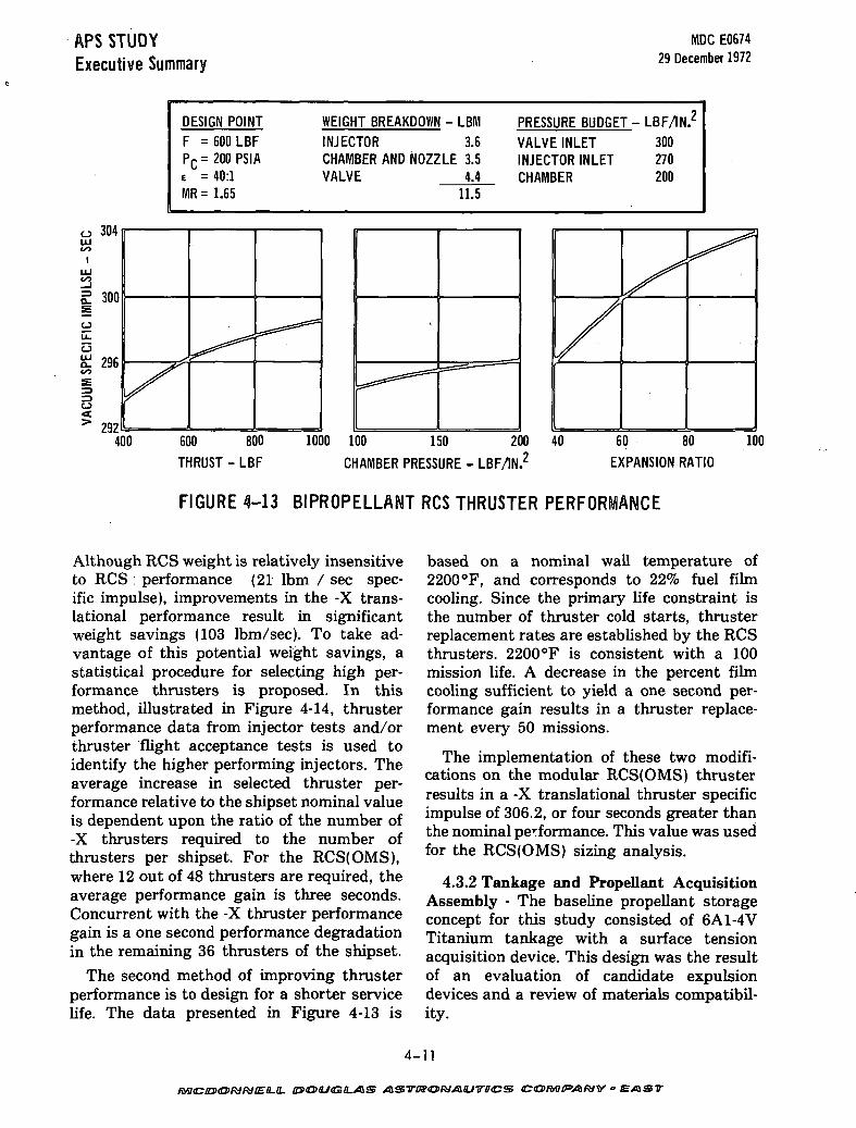
The bipropellant thruster model employedin this study was fuel film cooled, and con-sisted of a stainless steel parallel platelet in-jector and an integral thrust chamber andnozzle of silicide coated columbium. Figure4-13 presents the thruster performance sensi-tivities.
Two methods of maximizing the RCS(OMS)thruster performance have been implementedin this analysis:
1. Use of statistically determined higherperformance thrusters for the -X function.
2. Reduced thruster film cooling.
ETHYLENE PROPYLENE0-RINGS
BAYONET SEAL
INLET\VALVE
(REMAINSIN PLACE)
FIGURE 4-12 MONOPROPELLANT THRUSTER INSTALLATION
4-10
MCDONNELL DOUGLAS ASTRONAUTICS CO/frffVl/VV• EAST
APS STUDYExecutive Summary
MDC E067429 December 1972
DESIGN POINTF = 600 LBFPC=200PSIAe = 40:1MR= 1.65
WEIGHT BREAKDOWN - LBMINJECTOR 3.6CHAMBER AND NOZZLE 3.5VALVE 4.4
PRESSURE BUDGET - LBF/IN/
VALVE INLET 300INJECTOR INLET 270CHAMBER 200
11.5
o oiwLU
1LU
£ 300
o
c3Sj 296£
O
> 2924(
/
**f^f
^^
)0 600 800 100 150 200 40THRUST - LBF CHAMBER PRESSURE - LBF/IN.
60 80
EXPANSION RATIO
100
FIGURE 4-13 BIPROPELLANT RCS THRUSTER PERFORMANCE
Although RCS weight is relatively insensitiveto RCS : performance (21 Ibm / sec spec-ific impulse), improvements in the -X trans-lational performance result in significantweight savings (103 Ibm/sec). To take ad-vantage of this potential weight savings, astatistical procedure for selecting high per-formance thrusters is proposed. In thismethod, illustrated in Figure 4-14, thrusterperformance data from injector tests and/orthruster flight acceptance tests is used toidentify the higher performing injectors. Theaverage increase in selected thruster per-formance relative to the shipset nominal valueis dependent upon the ratio of the number of-X thrusters required to the number ofthrusters per shipset. For the RCS(OMS),where 12 out of 48 thrusters are required, theaverage performance gain is three seconds.Concurrent with the -X thruster performancegain is a one second performance degradationin the remaining 36 thrusters of the shipset.
The second method of improving thrusterperformance is to design for a shorter servicelife. The data presented in Figure 4-13 is
based on a nominal wall temperature of2200°F, and corresponds to 22% fuel filmcooling. Since the primary life constraint isthe number of thruster cold starts, thrusterreplacement rates are established by the RCSthrusters. 2200°F is consistent with a 100mission life. A decrease in the percent filmcooling sufficient to yield a one second per-formance gain results in a thruster replace-ment every 50 missions.
The implementation of these two modifi-cations on the modular RCS(OMS) thrusterresults in a -X translational thruster specificimpulse of 306.2, or four seconds greater thanthe nominal performance. This value was usedfor the RCS(OMS) sizing analysis.
4.3.2 Tankage and Propellant AcquisitionAssembly - The baseline propellant storageconcept for this study consisted of 6A1-4VTitanium tankage with a surface tensionacquisition device. This design was the resultof an evaluation of candidate expulsiondevices and a review of materials compatibil-ity.
4-11

APS STUDYExecutive Summary
MDC E067429 December 1972
APPROACH: THRUSTER PERFORMANCE DATA FROM INJECTOR TESTS AND/ORTHRUSTER FLIGHT ACCEPTANCE TESTS WILL BE USED TO SCREEN HIGH-PERFORMANCE THRUSTER S/N'S FOR THE AXIAL TRANSLATION FUNCTIONS
MARQUARDT R4D PERFORMANCE DISTRIBUTION434 THRUSTER SAMPLES
'SP_0
AVG 0 0.4 0.6 0.8NUMBER OF -X TRANSLATION THRUSTERS
1.0
NUMBER OF THRUSTERS PER SHIPSET
FIGURE 4-14 PERFORMANCE SCREENING OF RCS (QMS) THRUSTERS
Shuttle reusability requirements havelimited consideration of propellant acquisitionconcepts to nonmetallic bladders/diaphragms,metallic bellows, pistons and surface tensionpositive expulsion devices. Figure 4-15 sum-marizes the relative merits of these concepts.
Surface tension devices were chosen as thebaseline propellant acquisition method forthis study. Devices of this type are passive,thus providing high reliability and unlimitedreuse capability. The design consists of screenchannels located around the tank circum-ference, plus a single enclosed collector mani-fold which connects each channel to the outletsump.
The acquisition device will selectively passliquid to the feed system as long as there iscontact with the liquid mass. The wall orient-ed nature of the device ensures that thiscontact will be made. Screen mesh and flowpassage dimensions are selected so that the
pressure drop across the screen vapor/liquidinterface never exceeds the screen bubblepoint prior to reentry. During reentry, decel-eration forces result in channel draining;however, these same forces will orient thepropellant at the outlet of the tank forcontinued propellant use.
4.3.3 Pressurization Assembly - A regu-lated ambient temperature storage heliumpressurization system served as the referencefor this study. This system employs gaseoushelium stored at 4500 lbf/in.2 in titaniumpressure bottles. For bipropellant systems,the fuel and oxidizer have separate pressur-ization systems to preclude the possibility ofpropellant vapor mixing and reaction withinthe pressurization system. Propellant tankoperating pressure is maintained by the use ofpressure regulators, and redundancy isprovided with three parallel regulatorbranches.
4-12
MCDONNELL. DOUGLAS ASTRONAUTICS COMr*A*IY • EAST

APS STUDYExecutive Summary
MDC E067429 December 1972
CYCLE LIFE
RELATIVE WEIGHT
PERMEATION 'LEAKAGE
SENSITIVITY TO
DYNAMIC ENVIRONMENT
DEVELOPMENT STATUS
DEVELOPMENT RISK
MAJOR ADVANTAGES
MAJOR DISADVANTAGES
BLADDER 'DIAPHRAGM
150 (ELASTOMER)
15-30 (TEFLON)
1.0
HIGH PERMEATION
SUSCEPTIBLE TO TEARS
AND CLAMP-UP FAILURES
DURING SLOSH
GOOD
LOWEST RISK AND COST
SIMPLE. LIGHTWEIGHT
DEVICE
POOR CYCLE LIFE:
PERMEABLE MATERIALS:BLADDER ADSORBS
PROPELLANT
METALLIC BELLOWS
500
3.0
NEGLIGIBLE
PRONE TO CONVOLUTION
WEAR AND IMPACT
DAMAGE
GOOD
MODERATE: QUESTIONABLE
AVAILABILITY OF LARGE
DIAMETER. SEAMLESS
TUBING
POSITIVE SEPARATION OF
PROPELLANT AND PRES-
SURANT: CONTROL OF
FAILURE MODE BY SELEC-TION OF CORE SPRING
CONSTANT: GOOD PROPEL-
LANT STORABILITY
HEAVY AND DIFFICULT
TO CLEANCORROSION)
PISTON
1000
2.7
LIQUID FILM ON WALL
FOLLOWING EXPULSION
PISTON COCKING
FAIR
MODERATE:MAJOR
DEVELOPMENT EFFORT
ASSOCIATED WITH BACK-UP ROLLING DIAPHRAGM
SIMPLE DEVICE WITH
GOOD CYCLE LIFE
RESIDUAL LIQUIDFILM: EXPOSURE OF
DYNAMIC SEALS TOPROPELLANTS
SURFACE TENSION
UNLIMITED
1.3
SATURATED PROPELLANTS
CHANGE IN EFFECTIVE
PORE SIZE
GOOD -*• FAIR; SMALL
TANKS OR SUMPS
FAIR -»-POOR; LARGE TANKS
MODERATE TO HIGH:
UNABLE TO GROUND TEST
LARGE TANKS
PASSIVE DEVICE WITH
POTENTIAL FOR
UNLIMITED LIFE
DIFFICULT TO TEST
AND TO VERIFYINTEGRITY: DUTYCYCLE SENSITIVE
FIGURE 4-15 SUMMARY OF CANDIDATE EXPULSION DEVICES
In depth studies were conducted to eval-uate the weight savings potential offered byadvanced pressurization concepts. Pump fed,volatile liquid, and hydrazine decomposition(monopropellant systems only) pressurizationsystems were compared to the referenceregulated helium system from the viewpointsof weight and complexity. The alternatesystems are shown conceptually in Figure4-16.
A comparison of the primary considera-tions for the four concepts is presented inFigure 4-17. The significant conclusionsdrawn from these comparisons are:
1. For monopropellant systems, hydrazine
decomposition pressurization does showa weight savings over a regulated heliumsystem but at the expense of increasedcomplexity.
2. A pump feed system is lighter than itsregulated helium counterpart, again withincreased system complexity. Addition-ally, this system requires liquid pressureregulators, when used in bipropellantsystems; to avoid large mixture ratioexcursions.
3. Volatile liquid pressurization, althoughattractive from a reusable-refillable mod-ule aspect, is not weight competitivewith any of the other systems.
4-13
/frfCOO/V/VEf-i- DOUGLAS ASTKOMAUTICS COMPANY - EAST

APS STUDYExecutive Summary
Helium
MDC E067429 December 1972
HydrazineDecomposition
FILL
VENT
He PRESSUREPAD
FILL
FILL
VENT
VENTTO PROPELLANT
TANKTO MAIN
N2H4 TANK
Volatile Liquid
VENT FILL
PROPELLANTTANK
TOTHRUSTERS &OJFILL
TO THRUSTERS
FIGURE 4-16 ALTERNATE PRESSURIZATION CONCEPTS
RELATIVE WEIGHT-APU
-MONOPROPELLANT RCS- BIPROPELLANT RCS (OMSi
RELATIVE VOLUME
PRESSURE BAND
DESIGN OPERATING TEMPERATURE
SENSITIVITY TO MISSION DUTYCYCLE
PROPELLANT UTILIZATIONUNBALANCE ERROR CONTROLBUDGET
MAJOR ADVANTAGES
MAJOR DISADVANTAGES
REGULATED HELIUM
+ 137+ 375+ 700
5.0
* 25°.
AMBIENT
FAIRLY INSENSITIVE
SMALL
WIDE APPLICATION.MINIMAL DEVELOPMENT
HEAVY: HIGH REGULATOR FAILURE RATE
N2H4
DECOMPOSITION
+ 20REF
1.0
+ 21°,
200° F
FAIRLY INSENSITIVE
SMALL
LIGHTWEIGHT. REDUCESTHERMAL CONTROL
COMPLEX: TIGHT PRESSURE DEAOBANO NECESSITATES MANY PUMP CYCLES:REQUIRES HEAT EX
CHANGER
PUMP FEED
REF+ 100REF
2.0
+ 100*
- 0 '
AMBIENT
ACCUMULATOR SIZELIMITS RCSAV
LARGE 0/F ERRORFOR ACCUMULATORSOUT OF PHASE
LIGHTWEIGHT: PRESSURANT LEAKAGENOT CRITICAL
WIDE VARIATION INTHRUSTER INLETPRESSURE OR HIGHPUMP POWER:
VOLATILE LIQUID
+ 43+ 1075
+ 4400
2.2
+ 85*- 0 '
125 - 165°F
HEATER POWER LEVELLIMITS TOTAL RCS THRUST
LARGE ERRORS DUE TOMODULE TEMPERATUREDIFFERENCES
RELIABLE NO-NIOVINGPARTS. NO FILL VENTREQUIREMENT FOR RECYCLE
HEAVY: WIDE PRESSUREBAND: HIGH POWERREQUIREMENT
•"WITHOUT LIQUID PRESSURE REGULATION
FIGURE 4-17 COMPARISON OF CANDIDATE PRESSURIZATION CONCEPTS
4-14
MCDONNELL. DOUGLAS ASTRONAUTICS COMPANY • EAST

APS STUDYExecutive Summary
4.3.4 Thermal Control - Analysis was per-formed to evaluate the technical complexityand to define the weight implications associ-ated with the thermal control of the alternateBCS configurations.Module thermal control isrequired primarily to protect the system fromthe extreme environments in space, as well asthose induced during entry. Additionally,monopropellant thruster injectors requirecooling to preclude explosive decompositionof the propellant under certain malfunctionconditions. The primary thermal constraintsare associated with the propellants and thethrusters. Allowable propellant temperatureranges have been established to be 40 to125°F for bipropellants (NTO/MMH) and 50to 125 °F for monopropellant hydrazine. Thesteady state and transient thermal responseof the wing tip RCS modules have beenexamined using a two-dimensional thermalmodel. These calculations indicate that themaximum steady state uncontrolled temper-ature range is -110 to 165°F. Minimum tem-peratures, which occur with continuouslyshaded pods, require heaters to preventpropellant freezing. Heaters are sized toprovide a maximum power of 303 watts forthe monopropellant system (including 10watts per thruster to maintain a minimum150°F catalyst temperature), and 161 wattsfor a bipropellant system. Correspondingmaximum energy requirements are 36.8 kwh(monopropellant system) and 17.3 kwh (bi-propellant system). The maximum tempera-ture of 165 °F is somewhat above the desiredmaximum temperature, and thermal controlis required to prevent propellant overheating.
Thruster thermal requirements have beendefined in order to provide adequate thrusterlife and reliability. Figure 4-18 summarizesthe thermal limitations associated withmonopropellant thruster start up, operation,heat soakback, and nonoperation. Thecounteracting constraints on minimumcatalyst bed temperature and maximum in-jector soakback temperature are of primarysignificance. The restriction on minimumcatalyst temperature arises from the poorstructural properties of the spontaneouscatalyst (Shell 405) and its tendency to
MDC E067429 December 1972
generate "fines" under repeated cold thrusterstarts. The restriction on injector temperatureis based on propellant thermal stability con-siderations, i.e., the maximum injectortemperature is kept sufficiently low so as topreclude explosive detonation of the pro-pellant under certain malfunction conditions.
Thermal control of bipropellant thrusters isnot as restrictive. The primary concern forbipropellant thrusters is with vacuum-igni-tion pressure spiking. During pulsingoperation, energy-rich detonatable chemicalresidues (mostly monomethylhydrazine ni-trate) can accumulate and, in sufficientquantity, can produce high-magnitude igni-tion overpressures. To alleviate this problemon the Apollo CSM and LM RCS, the thrusterinjectors were maintained in excess of 70°F topromote rapid vaporization of the fuel.Meeting this same criteria with 600 Ibfthrusters will require a maximum power inputof 5.4 watts/thruster.
The basic aspect of monopropellant thrust-er thermal control is the conduction pathbetween the thruster and the surroundingstructure. To minimize the injector and valveseat temperature, it would be desirable toattach the injector and valve to massivestructure with a high heat capacity. However,such a connection would provide a substantialheat short during periods of nonoperation,and would thus conflict with the goal of mini-mizing the heater power required to maintainminimum catalyst temperature. Of the alter-nate thermal connection concepts which wereevaluated, the most attractive was a heatpipe.
In order to determine the operational con-siderations of a heat pipe system, a thermalmodel of the module was constructed. Thismodel was used to determine the steady stateheater requirements necessary to maintainthruster minimum temperatures, to deter-mine the heat delivered to the EnvironmentalControl and Life Support (ECLS) duringthruster soakback, and the system transientresponse. The thruster-ECLS model was usedto examine the response of the thruster, themounting plate, and the module during a heatsoakback condition. For the single firing case,
4-15
fwcin><a>RiKiEii.iL BS<a>ajGiLA&

APS STUDYExecutive Summary
MDC E067429 December 1972
o
LU
OO
OQ«£
15
10
Detonation Potential(304L SS LINES) o
ocLUQ.
DETONATABLE
DECOMPOSITION
•EXOTHERM
Q»
\\
o \§ >
\Bs
I
Catalyst Loss• 10 STARTS
0 40°FD 65°F
A 120°FkX
X
9.v-&.i i i
PROPELLANTPROPELLANTPROPELLANT
A
01 1
300 400 500PROPELLANT LINE TEMPERATURE -°F
50 100 150 200 250 300
REF: AFRPL TR 71-41
INJECTORTEMPERATURE
1500°F
INITIAL CATALYST TEMPERATURE - °F
REF: AFRPL TR 71-103
VALVE SEATTEMPERATURE f 200°F
/-BED TEMPERATURE2 150°F
MAXIMUM EXTERNALTEMPERATURE <600°F
600
FIGURE 4-18 MONOPROPELLANT THRUSTER THERMAL CONSTRAINTS
the injector temperature rises to 500°F whenuncontrolled. With the heat pipe, the injectortemperature rise is reduced and it is cooledmore rapidly. The problem is more servere,however, when multiple firings occur. For thiscase (Figure 4-19), soakback continued for2000 seconds. At that time, it was assumedthat a second pulse occurred in which thethruster and catalyst temperatures wereelevated to the steady state firing conditions.With a heat pipe system, the injector tem-perature does not exceed the 500 °F maximuminjector temperature. For the uncontrolledsystem using only the capacitance of themodule and the thruster mounting plate,however, the injector temperature rises toabout 560°F, well above the allowable limit.These thruster-module-ECLS calculations in-dicate that satisfactory operation can beachieved by linking the module to the ECLSwith heat pipes.
INJECTOR TEMPERATUREHEAT PIPE
4000
FIGURE 4-19 EFFECT OF PULSE
OPERATION ON THRUSTER
TEMPERATURE TRANSIENTS
4-16
MCDONNELL. DOUGLAS ASTKOMAUTICS COMPANY • EAST

APS STUDYExecutive Summary
KIDC E067429 December 1972
Steady state and transient thermalresponses have been examined for the fuse-lage mounted module. Maximum uncontroll-ed propellant temperatures (115°F) weresomewhat less than for the wing tip podbecause of additional communication with thevehicle. However, heater power levelsrequired to maintain minimum temperatureswere substantially higher, due to theincreased tank size and reduced thermalcommunication with earth. Tank structureand support transients have been examined toevaluate techniques for reducing the principalleaks. Tank support was provided by alumi-num structure cantilevered from the fuselageside. In this configuration there is no con-duction heat transfer from the tank to thethruster enclosure, and the thruster enclosureserves as a radiation shield between the tanksand space. The results show that to maintain40°F conditions for the four tanks in a modulesubjected to a cold environment requires an
10.5-
10.4-
10.3-
10.2-
o CHAMBER PRESSURE = 200 LBF/IN.2Ao ATTITUDE CONTROL THRUSTERS
EXPANSION RATIO = 40o X-TRANSLATIONAL THRUSTERS
EXPANSION RATIO = 40
input of 330 watts.
4.4 Concepts Comparison - System sizinganalyses were performed for the candidateconfigurations. Optimal design points weredetermined by generating system weightsensitivities to chamber pressure, expansionratio, and mixture ratio (for bipropellantsystems), as presented in Figure 4-20 for themodular bipropellant RCS. As shown, theexpansion ratios of the -X translationalthrusters have been optimized as an inde-pendent parameter. This results in a signifi-cant weight savings for the RCS(OMS); thesavings realized by the remaining systems areminimal and would not warrant the use of adifferent expansion ratio. Pod structure andthermal protection weight drives theoptimum modular RCS design points to lowexpansion ratio and high chamber pressure(both favoring smaller thrusters and thereforesmaller pods).
10.5-
10.4-
10.3-
10.2-
10.1-
o MIXTURE RATIO = 1.65o ATTITUDE CONTROL
THRUSTERS EXPANSIONRATIO = 40
o X-TRANSLATIONALEXPANSION RATIO = 40
1.0 1.2 1.4 1.6 1.8 2.0MIXTURE RATIO
o CHAMBER PRESSURE =
50 100 150 200CHAMBER PRESSURE - LBF/IN/A
10,300-
10,250-
UJ3= 10,200-
10,150-
200 LBF/IN.?Ao MIXTURE RATIO = 1.65 EX-TRANS= 20
eX-TRANS = 80
EX-TRANS= 60
eX-TRANS= 4°
20 40 60ATTITUDE CONTROL THRUSTERS
EXPANSION RATIO
80
FIGURE 4-20 SYSTEM WEIGHT SENSITIVITIESModular RCS-NTO/MMH
4-17
23><O><L/(G/LX5lS ASTDSORJAQJITIHCS EAST

APS STUDYExecutive Summary
Figure 4-21 summarizes the optimal designparameters and system weights. In order toprovide a common ground for weight com-parison, a total propulsion system weightcomprised of the applicable RCS, OMS, andAPU weight is included. The evaluation of adedicated OMS was not a part of this study.However, in order to properly compare thealternate concepts, a generic OMS was neces-sary. The OMS weight was derived from theOrbit Maneuvering System Trade Studies(Contract NAS 9-12755).
When comparing system weights, it isnecessary to differentiate between systemexpendables weight, which has a 1:1 tradeoffwith payload, and system inert weight, whichreduces payload by 1.4 Ib for each pound in-
MDC E067429 December 1972
crease. Thus, the proper method of comparingsystems is on. the basis of payload penalty.Comparisons on the basis of payload magnifythe weight penalty associated with modu-larized system concepts. Figure 4-22 presentsthe relative payload weights. Comparison ofthe candidate configurations reveals thefollowing:
1) The lightest system approach is realizedwith an integral, bipropellant RCS/OMSand a modular monopropellant APU.
2) The payload penalty for modularizing thebipropellant RCS and OMS is 2184 Ibm.
3) The modularized, bipropellant RCS(OMS)is almost 1300 Ibm heavier (on a payloadbasis) than the combined weight of a mod-ularized RCS and modularized OMS.
SYSTEM
MODULAR RCS
(MONOPROPELLANT)
MODULAR RCS(BIPROPELLANT)
MODULAR
RCS (OMS)
(BIPROPELLANT)
INTEGRATED
RCS/OMS(BIPROPELLANT)
INTEGRATED
RCS/APU(MONOPROPELLANT)
MODULAR APU(MONOPROPELLANT)
DESIGN SUMMARY
WING AND NOSE MODULES
HELIUM PRESSURIZATION
TITANIUM TANKAGESURFACE TENSION POSITIVE EXPULSION
CONVENTIONAL NOZZLE THRUSTERS
WING AND NOSE MODULES
HELIUM PRESSURIZATION
TITANIUM TANKAGESURFACE TENSION POSITIVE EXPULSION
FILM COOLED THRUSTERS
FUSELAGE AND NOSE MODULES
HELIUM PRESSURIZATION
TITANIUM TANKAGESURFACE TENSION POSITIVE EXPULSION
FILM COOLED THRUSTERS
COMMON TANKAGE LOCATED BELOW
PAYLOAD BAY
HELIUM PRESSURIZATIONTITANIUM TANKAGESURFACE TENSION POSITIVE EXPULSION
FILM COOLED THRUSTERS
COMMON TANKAGE LOCATED BELOW
PAYLOAD BAYHELIUM PRESSURIZATION (RCSlBOOST PUMP PRESSURIZATION (APU)
SURFACE TENSION POSITIVE EXPULSION
CONVENTIONAL NOZZLE THRUSTERS
ACTIVE. ACTIVE. IDLE. DORMANT APU
REDUNDANCY
WATER COOLED APU
AR FUSELAGE MODULESHELIUM PRESSURIZATION
TITANIUM TANKAGE
SURFACE TENSION POSITIVE EXPULSION
ACTIVE. ACTIVE. IDLE. DORMANT APU
REDUNDANCY
WATER COOLED APU
OPTIMAL DESIGN PARAMETERS
RCS IMPULSE
1.831.810
1.831.810
1.973.464
(RCS)
7.831.849
(OMS)
1.899.678
(RCS)
7.841.338
(OMS)
1.899.678
F
600
600
600
600
600
PTANK
312
368
250
250
272
766
PC
150
200
150
150
(RCSl
150
(OMS)
125(RCS)1000
(APU)
500
t
20(ATT CONT)
20(=X)
40(ATT CONT)
40
( • X )
60(ATT CONT)
80
( •X)
60(ATT CONTl
60( • X )
40(ATT CONT)
40( • X )
MR
1.65
1.65
1.65
'sp
228.8(ATT CONT)
228.8(:X)
296.1
(ATT CONT)
296.1
( • X )
299.1
(ATT CONT)
306.2(-X)
299.1
(ATT CONT)299.1
( X)
315.9
(OMSl
235.4(ATT CONT)
235.4
(• XI
WEIGHT
12.889 (12,889 - RCS)( 3,295 - APU)
(28,790 - OMS)*
44,974
10.133 (10,133 -RCS)
( 3,295 - APU)(28,790 - OMS)'
42.218
40,155 (40.155-RCS (OMS)
( 3,295 - APU)
43.410
37,360 (37, 360-RCS/OMS)( 3.295 - APU)
40,655
14.586 (14.586- RCS APU)
(28.790 - OMS)'
43.376
3.295
*OMS SPECIFIC IMPULSE = 313 SEC
FIGURE 4-21 DESIGN POINT SUMMARIES
4-18
DOUGLAS ASTRONAUTICS COMPANY • EAST

APS STUDYExecutive Summary
MDC E067429 December 1972
APU
CO
MONOPROP APU
FIGURE 4-22 RELATIVE PAYLOAD WEIGHTS
4) The modularized monopropellant RCShas a reduced payload of 3130 Ibm whencompared with the modularized bipropel-lant RCS.
Each configuration is the result of an individ-ual optimization; tankage and thruster loca-tions have been separately established, anddesign points defined consistent with theparticular requirements of each system. Thesefinal comparisons are therefore considered tobe realistic evaluations of the alternate con-figurations. One significant advantageafforded by integral systems is weight, butthe maintenance complications associatedwith integral systems are unacceptable for areusable vehicle. Consequently, only modularsystems can be seriously considered for use onShuttle.
As discussed in Section 1, the objective ofthis study was to develop design and pro-grammatic data for competitive reactioncontrol systems in sufficient detail that aselection can be made between the variousconcepts. In keeping with this objective, theconcluding effort in this study was an assess-ment of the weight implications of selectedconfiguration changes on the design pointweights. The effects of changes in pres-surization concept, type of tank expulsion,and tank material are shown in Figure 4-23 forthe modular bipropellant RCS. Weightsavings are possible in the area of pressur-ization, with the largest savings available forthe high impulse configurations (modularRCS(OMS) and integrated RCS/OMS). In
4-19
/VfCDO/V/Vff-f. DOUGLAS ASTRONAUTICS CO IMF*A IVY • EAST

APS STUDYExecutive Summary
general, the pump fed pressurization conceptoffers the largest savings; however, its adop-tion results in increased system complexity.By contrast, the savings afforded by compos-ite pressurant tanks reflect no decrease in sys-tem reliability. Additionally, composite tanksgenerally provide a leakage failure mode
MDC E067429 December 1972
rather than fracture. The weight penalties as-sociated with system redundancy are also pre-sented to allow evaluation of the weightpenalty associated with the fail safe/fail saferedundancy philosophy. The weight savingsshown represent the elimination of all com-ponents except those necessary for comple-tion of a failure free mission.
SYSTEM
BASELINE SYSTEM: TWO WING TIP AND ONE NOSE-MOUNTED MODULES CONTAINING A TOTALOF FORTY 600 LBF FILM COOLED THRUSTERS, HELIUM PRESSURIZATION,TITANIUM TANKS.AND SURFACE TENSION POSITIVE EXPULSION.
RELATIVE SYSTEM WEIGHT-600 -400 -200 0 +200 + 400 + 600
PRESSURIZATION- VOLATILE LIQUID-PUMPREDUNDANT EXPULSION TANKS- POSITIVE EXPULSION DEVICE (SCREEN TANK)- BLADDER- BELLOWS- PISTON
TANK MATERIAL-301 CRYOFORM- COMPOSITE PRESSURANT TANKS
NON-REDUNDANT CONFIGURATION-VALVES, REGULATORS, ETC.- THRUSTERS
-59-339
-121
J+642
100 +1707
J *230+1399
REFERENCE WEIGHT = 10,133 LBM
FIGURE 4-23 WEIGHT RELATIVE TO BASELINE MODULAR RCS (N204/MMH)
As originally defined, Phase E was to be afinal performance analysis of the six systemsdescribed above. However, prior to thecompletion of this evaluation, NorthAmerican Rockwell (NR) was awarded theSpace Shuttle Orbiter prime contract byNASA. The NR shuttle configurationemploys a dedicated bipropellant OMS and amonopropellant RCS installed in fuselage andnose modules. The RCS utilizes 40 thrustersof 1000 Ibf each. Common size propellant andpressurant tanks are used in the nose andfuselage modules. In order to maximize theutility of the APS study results, additional
analysis was performed to further study thefuselage module options. Five alternatefuselage configurations were evaluated:
1. Dedicated OMS, common RCS-OMStankage
2. Common RCS-OMS thrusters, commontankage (the RCS(OMS) of Phase E)
3. Dedicated OMS, dedicated tankage (bi-propellant RCS)
4. Common RCS-OMS thrusters, dedicatedtankage
5. Dedicated OMS, dedicated tankage(monopropellant RCS)
4-20
MCDONNELL DOUGLAS ASTITOn/Al/TICS COMPANY • EAST
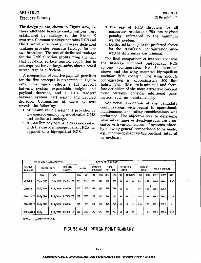
APS STUDYExecutive Summary
The design points, shown in Figure 4-24, forthese alternate fuselage configurations wereestablished by analogy to the Phase Esystems. Common tankage contains RCS andOMS propellants jointly, whereas dedicatedtankage provides separate tankage for thetwo functions. The use of dedicated tankagefor the OMS function profits from the factthat full-tank surface tension acquisition isnot required for the large tanks, since a smallscreen trap is sufficient.
A comparison of relative payload penaltiesfor the five concepts is presented in Figure4-25. This figure reflects a 1:1 tradeoffbetween system expendable weight andpayload decrease, and a 1:1.4 tradeoffbetween system inert weight and payloaddecrease. Comparison of these systemsreveals the following:
1. Minimum vehicle weight is provided bythe concept employing a dedicated OMSand dedicated tankage.
2. A 2700 Ibm payload penalty is associatedwith the use of a monopropellant RCS, asopposed to a bipropellant RCS.
IWDC E067429 December 1972
3. The use of RCS thrusters for allmaneuvers results in a 750 Ibm payloadpenalty, referenced to the minimumweight system.
4. Dedicated tankage is the preferred choicefor the RCS(OMS) configuration, sinceweight differences are minimal.
The final comparison of interest concernsthe fuselage mounted bipropellant RCSconcept (configuration No. 3) describedabove, and the wing mounted bipropellantmodular RCS concept. The wing moduleconfiguration is approximately 300 Ibmlighter. This difference is minimal, and there-fore definition of the more attractive conceptmust certainly consider additional para-meters, such as maintainability.
Additional evaluation of the candidateconfigurations with regard to operational,maintenance, and safety considerations wasperformed. The objective was to determinewhat advantages or disadvantages are asso-ciated with various classes of systems, there-by allowing general comparisons to be made,e.g., monopropellant vs bipropellant, integralvs modular.
POD DESIGN CHARACTERISTICS
RCS 'OIYIS
TANKAGE
COMMON
COMMON
DEDICATED
DEDICATED
DEDICATED
PROPELLANTS
RCS
N204 'MMH
N204 'MMH
N20, ViMH
N204'MMH
N2H4
OMS
N204 'MMH
N204 'MMH
N204 'MMH
N204.'MMH
N204 WMH
RCS 'OMS
ENGINES
DEDICATED
COMMON
DEDICATED
COMMON
DEDICATED
SYSTEM DESIGN POINTS
THRUST
RCS
600
600
GOO
600
600
OMS
6000
600
6000
600
6000
CHAMBER
PRESSURE
RCS
150
ISO
175
150
125
OMS
150
150
125
150
125
TANK
PRESSURE
RCS
249
249
285
249
235
OMS
249
249
205
249
205
EXPANSION
RATIO
RCS
60
60
60
60
40
+XRCS
60
90
60
90
40
OMS
90
-
75
-
75
MIXTURE
RATIO
RCS'
1.65
1.65
1.65
1.65
-
OMS
1.65
1.65
1.65
1.65
1.65
SPECIFIC IMPULSE
RCS(')
299.1
299.1
299.3
299.1
235.3
X R C S
299.1
306.2
299.3
306.2
235.3
OMS
315.9
-
313.5
-
313.5
(1) USE 76'. lsp (SS) FOR PULSING
FIGURE 4-24 DESIGN POINT SUMMARY
4-21
/MODO/V/Vf«.(. DOUGLAS ASTRONAUTICS COMPANY * EAST

APS STUDYExecutive Summary
MDC E067429 December 1972
3000
i>-
2000
O_
O
O
* 1000LU
2701
745
REFERENCE
701
169
TANKAGE
ENGINES DEDICATED
PROPELLANT
DEDICATED COMMON
COMMON DEDICATED DEDICATED COMMON
NTO/MMH NTO/MMH
FIGURE 4-25 COMPARATIVE PAYLOAD PENALTIES FORCANDIDATE TANK/ENGINE SYSTEMS
4.5 Reusability Effects - Propellant handl-ing considerations have a considerableinfluence on earth storable system designs.Due to the toxicity, corrosiveness and, in thecase of bipropellants, hypergolic nature of thepropellants, safety considerations dictate thatonly those personnel directly involved in RCSservicing be allowed in the proximity of thesystem during these operations. For a systemthat is installed integrally within the vehicle,t,his constraint would force vehicle mainte-nance operations to be conducted serially, andwould extend the vehicle turnaround time byapproximately two days. To meet the Shuttleobjective of a two week turnaround, attentionhas focused on the use of removable, self-con-tained modules. The modules would beremoved from the vehicle after landing andtaken to a remote facility suitable for safemaintenance and filling operations. Vehiclemaintenance could then proceed without
elaborate precautions. The following dis-cussion defines the anticipated maintenanceprocedures, assuming a modularized propul-sion system.
The major portion of the system will remain"wet" but it is considered necessary to purgedry the thruster assemblies for safety andreuse. System safing will begin during re-entry, following vehicle transition to airplanemode of flight. At this time, propellant isola-tion valves will be closed and the thruster as-semblies purged with residual helium pres-surant.
Figure 4-26 summarizes the ground safingand servicing requirements. After vehiclelanding and cooldown, system depressuriza-tion will be verified and a nitrogen purge ofthe thrusters will be performed to assure thatall propellants have been cleared. Systempower will then be removed and thrusterthroat plugs will be installed.
4-22
/VTCOO/V/VELf. DOUGLAS ASTRONAUTICS COMFANY • EAST

APS STUDYExecutive Summary
MDC E067429 December 1972
Safing Area
L J >^x
OPERATION• PURGE THRUSTERS• DEPRESSURIZE SYSTEM• INSERT THRUSTER
THROAT SEALS. REMOVE SYSTEM DATA TAPES• REMOVE MODULES Hypergolic Building
NORMAL OPERATION• VISUALLY INSPECT. PERFORM THRUSTER LEAK TESTS. FUNCTIONALLY TEST VALVE
DRIVER CIRCUITS• FUNCTIONALLY TEST HEATER
SYSTEM• LOAD PROPELLANTS• MOVE MODULE TO VABMAINTENANCE• DRAIN & DECONTAMINATE SYSTEM. PURGE SYSTEM WITH HOT GN2
. REMOVE & REPLACE FAULTY COMPONENTS
. FUNCTIONALLY TEST REPAIRS
VAB and Launch Area
OPERATION. INSTALL MODULES IN VEHICLE• VALIDATE ELECTRICAL CONNECTIONS. REMOVE THRUSTER THROAT SEALS• SERVICE HELIUM BOTTLES• PRESSURIZE PROPELLANT TANKS
FIGURE 4-26 GSE REQUIREMENTS
4-23
MCDOftlNELL. DOUGLAS ASTRONAUTICS CO/tfffVl/VV • EAST

APS STUDYExecutive Summary
Propulsion modules will be removed to aremote facility for servicing. Normal servicingwill include such operations as testing valvedriver circuits and the heater system and per-forming leak checks. The tanks and controlcomponents will be maintained wet to themaximum extent possible. Gravity fill proce-dures will be employed, and propellant quan-tities determined by weight (modules re-moved) or by overfilling and metering off therequired ullage volume (modules installed).
Maintenance operations will be performedbased on inflight checkout intelligence data.Failure probability analyses show that the re-quired system repair frequency will be high.As shown in Figure 4-27, estimates vary froma propellant system failure every 1 to 3 flightsfor a bipropellant RCS and a propellant sys-tem failure every 1 to 5 flights for a monopro-pellant RCS. These numbers illustrate theimportance of component accessibility in re-ducing maintenance downtime. A review ofcomponent failure data from previously flownspacecraft has indicated that the primarycause of failure is contamination, and thecomponents most susceptible to contamina-tion are the pressurant check valves and thepropellant valves. System reliability and re-usability would be benefited by maintainingthe propellant feed system in a wetted condi-tion.
MDC E067429 December 1972
The replacement of propellant systemcomponents other than thrusters and pres-surization components would require eithercomplete or partial system draining and flush-ing to remove residual propellants from thesystem in order to assure a safe environmentfor maintenance personnel. Of the variouscleaning methods available, the single-flushmethod and the vapor-phase flush method, inwhich the solvent is introduced into the sys-tem in its vapor phase, appear to be the mostpromising approaches for decontamination ofthe shuttle RCS when necessary. A review ofavailable solvents has identified Isopropanoland Freon TF as the most attractive solventsfor fuel and oxidizer systems, respectively.
Several conclusions regarding reuse areapplicable regardless of the configurationchosen. The successful implementation of amulti-mission vehicle will require thoroughconsideration of reusability throughoutsystem design, including the establishment ofthermal control requirements consistent withreusability, and in the definition of servicing,safing and maintenance operating procedures.The safety and reuse criteria identified in thisstudy have been so categorized, and are sum-marized in Figure 4-28. Reuse considerationsnecessitate added care in the selection ofcomponent types and arrangement to mini-mize the generation and effects of contami-nants on system operation.
SUBSYSTEM ASSEMBLY
TOTAL RCS
TOTAL RCS LESS INSTRUMENTATION
RCS INSTRUMENTATION
PRESSURIZATION COMPONENTS
PROPELLANT STORAGE AND CONTROL
PROPELLANT TANKS & FILL VALVES
THRUSTER ASSEMBLIES
MONOPROPELLANTMISSIONS
1.0 -4.7
1.4 -6.6
4.1 -16.5
10.4 — -57.3
6.5 -52.0
19.1— * 187.0
2.1 -8.8
BIPROPELLANT
MISSIONS
0.7 -2.9
0.9 -3.7
3.5 -14.3
5.0 — -25.3
4.1 -31.8
23.4 — 224.0
1.4 -5.0
FIGURE 4-27 MEAN TIME BETWEEN COMPONENT FAILUREModular RCS
4-24
MCDONNELL DOUGLAS ASTKONAUTICS COMFAhlY - EAST

APS STUDY MDC E0674
Executive Summary 29 December 1972
Design• PROVIDE SYSTEM ACCESS WITH VEHICLE IN EITHER HORIZONTAL OR VERTICAL (LAUNCH) ATTITUDE• EMPLOY INTERLOCKS OR OTHER SAFEGUARDS ON MANUAL VALVES TO ASSURE VALVES ARE IN FLIGHT
POSITION PRIOR TO LIFT-OFF• USE SEPARATE PRESSURANT SUPPLIES FOR FUEL AND OXIDIZER• DESIGN FOR FAIL-SAFE, FAIL-SAFE REDUNDANCY OR BACK-UP CAPABILITY ON ALL ACTIVE COMPONENTS• USE COMPOSITE (OVER WRAP) PRESSURANT TANKS TO ASSURE TANK FAILURE IS BY LEAKAGE RATHER
THAN FRACTURE. EMPLOY FLEXIBLE PROOF TEST FACTORS ON PRESSURE VESSELS, ADJUSTING FOR TANK MATERIAL
ENVIRONMENT, HOOP LOADS AND REQUIRED LIFE. PROOF TEST WITH LIQUID NITROGEN TO REDUCEREQUIRED PROOF PRESSURE LEVELS AND/OR TO VERIFY GREATER CYCLE LIFE FOR GIVEN DESIGNSAFETY FACTOR
• USE MATERIALS THAT ARE COMPATIBLE WITH PROPELLANTS AND RESIDUES FORMED BY PROPELLANTREACTION WITH THIRD AGENTS, I.E., H20, C02, SOLVENTS, ETC
• PROVIDE REPLACEABLE COMPONENT CARTRIDGES FOR HIGH FAILURE RATE ITEMS• USE BREAKABLE SEALS BETWEEN MONOPROPELLANT THRUSTER AND THRUSTER VALVES TO FACILITATE
CATALYST REPLACEMENT
Thermal Control• THERMALLY CONTROL TO FOLLOWING TEMPERATURE CONSTRAINTS:
(°F)N2H4 THRUSTER CATALYST> 150 (CATALYST LIFE)
INJECTOR < 500 (DETONATION POTENTIAL)VALVE < 200 (SEAT LIFE)
N204/MMH THRUSTER INJECTOR > 70 (IGNITION PRESSURE SPIKING)VALVE <200 (SEAT LIFE)
PROPELLANTS N2H4 > 50 (FREEZING)N204/MMH > 40 (IGNITION PRESSURE SPIKING/N204 FREEZING)
Sating and Maintenance• PERFORM POST-DEACTIVATION FLIGHT PURGE OF THRUSTER ASSEMBLIES. DEPRESSURIZE SYSTEM FOR GROUND SERVICING AND/OR POD TRANSPORT• INSERT THRUSTER THROAT SEALS AFTER LANDING• MAINTAIN WET TANK AND CONTROL COMPONENTS TO MAXIMUM PRACTICAL EXTENT. WHEN NECESSARY,
FLUSH SYSTEM WITH VAPORIZED SOLVENTS (FREON TF-NTO; ISOPROPANOL - MMH, N2H4) FOLLOWED BYHOT GN2 PURGE. PULSATE FLOW OF GASIFIED SOLVENTS TO SCAVENGE PROPELLANT VAPORS).
• PROVIDE CLOSED-VENT SYSTEM FOR PROPELLANT DUMP• AVOID AIR DRY OF EPT RUBBER EXPULSION BLADDERS
Servicing• UTILIZE MOLECULAR SIEVES TO REMOVE SOLUBLE IRON FROM N204 PROPELLANT DURING FILL OPERA-
TIONS (MINIMIZE RHEOPEXY POTENTIAL)• EMPLOY GRAVITY FILL PROCEDURES FOR PROPELLANT SERVICING. AVOID BACKFILL THROUGH SCREEN SURFACE TENSION TANKS TO AVOID SCREEN LOADING IN UNSUPPORTED
DIRECTION. AVOID PROPELLANT TEMPERATURE CONDITIONING DURING FILL. VERIFY PROPELLANT LOAD BY COMPLETELY
FILLING TANKS AND OFF-LOADING ULLAGE
FIGURE 4-28 SAFETY AND REUSE CRITERIA
4-25
MCDONNELL DOUGLAS ASTRONAUTICS COMPANY • EAST

APS STUDYExecutive Summary
MDC E067429 December 1972
5. STUDY CONCLUSIONS
Candidate oxygen/hydrogen propellantauxiliary propulsion systems were comparedon the basis of weight, technology, simplicity,flexibility, and reusability. Three oxygen/hydrogen turbopump RCS configurationswere evaluated with respect to operationalcharacteristics and controls requirements. Allthree configurations were judged to becompetitive, with the series-downstream tur-bine RCS offering a slight advantage. Tech-nology concerns associated with this class ofsystem include a high conditioner cycle liferequirement and excessive turbopump shaftaccelerations.
On the basis of weight, the most attractivesystem was an oxygen/hydrogen system inwhich the propellents are delivered to thethrusters as liquids. In addition, this systemconcept escapes the conditioner life and turbo-pump shaft acceleration technology concernsassociated with the oxygen/hydrogen turbo-pump RCS.
A change in orbiter design during the studyreduced RCS impulse requirements and pro-moted renewed interest in earth storable pro-pellant systems. Figure 5-1 shows that, evenat smaller orbiter impulse levels, a storablesystem weighs on the order of 3,000 to 5,000
CX3
CO
16,000
14,000
12,000
10,000
8,0
6,000
4,000
STORABLESORBITER
IOXYGEN/HYDROGENORBITER
G02/GH2
SERIES(TURBINE DOWNSTREAM)
PUMPED LH2
PRESS'D L02
1.5 1.75 2.0 2.25
TOTAL IMPULSE - 106 LBF-SEC
2.5
FIGURE 5-1 COMPARISON OF MODULAR STORABLE RCS CONCEPTSWITH INTEGRAL CRYOGENIC RCS CONCEPTS
5-1
MCDONNELL. DOUGLAS ASTKONAUTICS COMPANY • EAST

APS STUDYExecutive Summary
MDC E067429 December 1972
Ibm more than a liquid-liquid oxygen/hydro-gen system. However, the reduced volume ofthe smaller orbiter does not allow use of anoxygen/hydrogen OMS. This weight differ-ence could not justify the high cost and tech-nology risk associated with the developmentof an oxygen/hydrogen RCS alone. Thus,earth storable propellant systems were se-lected for the RCS and oxygen/hydrogenpropellants were eliminated from further con-sideration.
Three basic storable propellant conceptswere defined: a modular concept utilizingwing and nose modules, a modular conceptutilizing fuselage and nose modules, and anon-modular concept wherein the RCS was in-
tegral with the vehicle. For each concept,alternate configurations were defined byspecifying the propellants (monopropellant orbipropellant) and either common or dedicatedtankage and RCS thrusters/OMS engines.
Integral systems suffer, relative to modularsystems, in the areas of safety, ease of main-tenance, development flexibility, and growthpotential. Although attractive from a weightstandpoint, the above considerations are suf-ficient to eliminate integral systems fromcontention.
Figure 5-2 summarizes the relativeadvantages of wing and fuselage modularsystems. No clearcut preference is evident;weights are comparable, and no significant
WING TIP POD FUSELAGE POD
WEIGHT
CONTROL
10,133 LBM
[IMPULSE REQUIREMENTS MINIMIZED BY LARGE MOMENTARMS. (FINE CONTROL MORE DIFFICULT TO ACHIEVE).THRUSTER LOCATIONS MINIMIZE CROSS-COUPLING
10,400 LBM
BIAS DISTURBANCE TORQUES (YAW)
RESULT IN UNEQUAL PROPELLANTEXPENDITURE BETWEEN PODS FORON-ORBIT CONTROL
SAFETY/
MAINTENANCE
POD LOCATIONS FACILITATE REMOVAL/INSTALLATION
OPERATIONS. COMPONENT ACCESSIBILITY MOREDIFFICULT (PODS REMOVED) BECAUSE OF TOTAL
^ENCLOSURE - MORE ACCESS DOORS
POD ACCESS DIFFICULT BECAUSE OF POD
LOCATION OVER THE WING. COMPONENTSEASILY ACCESSIBLE WITH PODS REMOVED
THERMALCONTROL
UNCONTROLLED TEMPERATURE RANGE - 110°F TO
+ 165°F. MDAC-RSI AVERAGE UNIT WEIGHT = 2.34LBM; FT2
THRUSTER HEATERS - 5.4 WATTS/THRUSTERTANK HEATERS - 140 WATTS
DOORS REQUIRED OVER FWD-FACING THRUSTERS
UNCONTROLLED TEMPERATURE RANGE
-120°FTO+115°F. MDAC-RSI AVERAGEUNIT WEIGHT = 1.65 LBF/FT2
THRUSTER HEATERS - 5.4 WATTS/THRUSTERTANK HEATERS - 50 WATTS
AFFECT ONAERODYNAMICS
EFFECTS MINIMIZED BY. KEEPING PODS ON TOP SIDE OF WING (HYPERSONIC
STABILITY). MINIMIZING POD FRONTAL AREA (DRAG)TAPERING OF ELEVONS IS REQUIRED TO PROVIDESUFFICIENT WING STRUCTURE FOR POD SUPPORT
EFFECTS MINIMIZED BY
. MINIMIZING POD FRONTAL AREA (DRAG)
. POD BOATTAIL (BASE DRAG)
MINIMAL Jl EFFECTS ON CONTROL
SURFACES DUE TO AFT LOCATION OFCONTROL THRUSTERS
SEVERITY OF
DYNAMICENVIRONMENTS
UNSTEADY FLOW ON WING MAY INDUCE WING/PODRESPONSE THAT COULD RESULT IN FLUTTER HIGHACCELERATION AND PROPELLANT SLOSH LOADSLIKELY BECAUSE OF RCS LOCATION (REMOTE FROMVEHICLE CG)
MINIMAL EFFECT ON TANKAGE DUE TO
CLOSE PROXIMITY TO VEHICLE ROLLAXIS
FIGURE 5-2 WING-TIP/FUSELAGE POD COMPARISONBipropellant N204/MMH
5-2
MCDONNELL. DOUGLAS ASTRONAUTICS COMPANY - EAST

APS STUDYExecutive Summary
MDC E067429 December 1972
technology concerns impact either concept.However, the wing modules do complicatewing design, and the forward firing thrusterprotection doors are unattractive. These con-siderations, coupled with the benefits asso-ciated with the design and development of aconsolidated propulsion system make thefuselage module concept the better choice.
Within a fuselage module concept, threeviable configurations remain: a dedicatedOMS,coupled with either a monopropellant ora bipropellant RCS, and a bipropellant RCSfor all maneuvers. For each system, dedicatedtankage is more attractive than commontankage due to lessened development risk.Based on the study criteria, the dedicatedOMS - bipropellant RCS is the most attrac-tive concept. However, cost considerations,
not included in this study could alter thisposition. The monopropellant RCS suffers asignificant weight penalty, but potentiallyoffers reduced development effort and,possibly, reduced maintenance requirements.Cost trades between reduced developmentcosts but increased operational costs (due tothe payload penalty) are necessary to definethe monopropellant RCS potential. TheRCS(OMS) is weight competitive with thededicated RCS-OMS configuration and, addi-tionally, would be less costly since it deletesthe costs associated with the OMS engine de-velopment. This concept suffers in compari-son to the dedicated RCS-OMS configurationsolely on the basis of its reduced flexibility tofuture increases in translational thrust re-quirements, e.g., potential future high thrustrequirements for ascent abort.
5-3
MCDOfiHVELL DOUGLAS ASTRONAUTICS CO/V»*V»/VK • EAST

APS STUDYExecutive Summary
MDC E067429 December 1972
6. REFERENCES
A. Kendall, A.S., McKee, H.B., and Orton,G.F., "Space Shuttle Low Pressure Auxil-iary Propulsion Subsystem Definition -Subtask A Report", McDonnell DouglasReport No. MDC E0303, 29 January 1971.
B. Green, W.M., and Patten, T.C., "SpaceShuttle Low Pressure Auxiliary Propul-sion Subsystem Definition - Subtask B Re-port", McDonnell Douglas Report No.MDC E0302, 29 January 1971.
C. Anglim, D.D., Baumann, T.L., and Ebbes-meyer, L.H., "Space Shuttle High Pres-sure Auxiliary Propulsion Subsystem De-finition Study - Subtask A Report",McDonnell Douglas Report No. MDCE0299, 12 February 1971.
D. Gaines, R.D., Goldford, A.I., and Kaem-ming, T.A., "Space Shuttle High PressureAuxiliary Propulsion Subsystem Defini-tion Study - Subtask B Report",McDonnell Douglas Report No. MDCE0298, 12 February 1971.
E. Orton, G.F. and Schweickert, T.F., "SpaceShuttle Auxiliary Propulsion System De-sign study - Phase A Requirements Defini-tion", McDonnell Douglas Report No.MDC E0603, 15 February 1972.
F. Orton, G.F., and Schweickert, T.F.,"Space Shuttle Auxiliary Propulsion Sys-
tem Design Study • Phase B Report,Candidate RCS Concept Comparisons",McDonnell Douglas Report No. E0567, 15February 1972.
G. Bruns, A.E., and Regnier, W.W., "SpaceShuttle Auxiliary Propulsion SystemDesign Study - Phase C Report, OxygenHydrogen RCS/OMS Integration Study",McDonnell Douglas Report No. MDCE0523, 15 June 1972.
H. Baumann, T.L., Patten, T.C., and McKee,H.B., "Space Shuttle Auxiliary PropulsionSystem Design Study - Phase D Report,Oxygen-Hydrogen Special RCS Studies",McDonnell Douglas Report No. MDCE0615, 15 June 1972.
I. Anglim, D.D., Bruns, A.E., Ferryman,D.C., and Weiland, D.L., "Space ShuttleAuxiliary Propulsion System DesignStudy - Phase C and E Report, StorablePropellants, RCS/OMS/APU IntegrationStudy", McDonnell Douglas Report No.MDC E0708, 29 December 1972.
J. Kelly, P.J., "Space Shuttle AuxiliaryPropulsion System Design Study - Pro-gram Plan", McDonnell Douglas ReportNo. MDC E0436, 15 July 1971, revised 6December 1971.
6-1
/VfCDO/V/VtLL DOUGLAS ASTttOHIAUTICS CO/VffVt/VV - EAST

/VfCOO/V/VE'f-f. DOUGLAS ASTRONAUTICS
Samt Louis, Missouri 63166 (314) 232-0232
- EA:
/VfCDO/V/VEI_l_ DOUGLAS