Embed Size (px)
Citation preview

• Bullet-proof German-engineered hydraulic and electrical systems• Outstanding features and lift capacity performance• Fully rigged and counterweighted job site travel• Strongest winch line pull in its class
All-Terrain Crane130-ton (117.93 mt)
Upper structure• Mercedes Benz engine with
177 hp (130 kW)• Central lubrication system• Boom hoist float and swing brake
release for boom dolly applications• Fine inching mode• High speed mode• Free swing and automatic swing brake
modes
Operator’s cab• Tilting interior where the operator’s
seat, joystick controllers, floor controls and pedals, and main console tilt within the cab
• Crane instrumentation and operational documents have North American units of measure
• Outrigger, drive and steering controls• Air conditioning• Power front window• Integrated cab walks• Cab floodlight
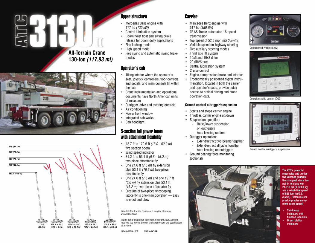
5-section full power boom with attachment flexibility• 42.7 ft to 170.6 ft (13.0 - 52.0 m)
five section boom• Wind speed indicator• 31.2 ft to 53.1 ft (9.5 - 16.2 m)
two piece offsettable fly• One 24.6 ft (7.5 m) fly extension
plus 53.1 ft (16.2 m) two-piece offsettable fly
• One 24.6 ft (7.5 m) and one 19.7 ft (6.0 m) fly extension plus 53.1 ft (16.2 m) two-piece offsettable fly
• Erection of two-piece telescoping lattice fly is one-man operation — easy to erect and stow
Carrier• Mercedes Benz engine with
517 hp (380 kW)• ZF AS-Tronic automated 16-speed
transmission• Top speed of 52.8 mph (85.0 km/hr)• Variable speed on-highway steering• Five auxiliary steering modes• Third axle lift system• 10x6 and 10x8 drive• 20.5R25 tires• Central lubrication system• Cruise control• Engine compression brake and intarder• Ergonomically positioned digital instru-
mentation, located in both the carrier and operator’s cabs, provide quick access to critical driving and crane operation data.
Ground control outrigger/suspension
• Starts and stops carrier engine• Throttles carrier engine up/down• Suspension operation:
- Raise/lower suspension on outriggers
- Auto leveling on tires• Outrigger operation:
- Extend/retract two beams together- Extend/retract all jacks together- Auto leveling on outriggers
• Ground bearing force monitoring (optional)
The ATC’s powerful, responsive and produc-tive winches generate the strongest winch line pull in its class with 21,010 lbs (9 530.0 kg) and a winch line speed of 526 fpm (160.21 m/min). Piston motors provide precise move-ment at any speed.
• Third wrap indicators with function lock-outs
• Drum rotation indicators
Cockpit multi-vision (CMV)
Cockpit graphic control (CGC)
Ground control outrigger / suspension
Link-Belt Construction Equipment, Lexington, Kentuckywww.linkbelt.com
®Link-Belt is a registered trademark. Copyright 2005. All rights reserved. We reserve the right to change designs and specifications at any time.
Litho in U.S.A. 336 03/05 #4304

15451 (supersedes 5446)---0505---P4
ATC-3130 IILink-Belt Cranes
Technical DataSpecifications & Capacities
Telescopic Boom All Terrain Crane130 ton (117.9 metric ton)
CAUTION: This material is supplied forreference use only. Operator must refer toin---cab Crane RatingManual andOperator’sManual to determine allowable crane liftingcapacities and assembly and operatingprocedures.

5451 (supersedes 5446)---0505---P4
ATC-3130 II Link-Belt Cranes

5451 (supersedes 5446)---0505---P4
ATC-3130 IILink-Belt Cranes
Table Of ContentsBoom, Attachments, and Upper Structure 1. . . . . . . . . . . . . . . . . . . . . . . . . . . . . . . . . . . . . . . . . . . . . . . . . . . .Boom 1. . . . . . . . . . . . . . . . . . . . . . . . . . . . . . . . . . . . . . . . . . . . . . . . . . . . . . . . . . . . . . . . . . . . . . . . . . . . . . . . . . . .Boom Head 1. . . . . . . . . . . . . . . . . . . . . . . . . . . . . . . . . . . . . . . . . . . . . . . . . . . . . . . . . . . . . . . . . . . . . . . . . . . . .Boom Elevation 1. . . . . . . . . . . . . . . . . . . . . . . . . . . . . . . . . . . . . . . . . . . . . . . . . . . . . . . . . . . . . . . . . . . . . . . . . .Auxiliary Lifting Sheave --- Optional 1. . . . . . . . . . . . . . . . . . . . . . . . . . . . . . . . . . . . . . . . . . . . . . . . . . . . . . . . .Hook Blocks and Balls --- Optional 1. . . . . . . . . . . . . . . . . . . . . . . . . . . . . . . . . . . . . . . . . . . . . . . . . . . . . . . . . .Fly --- Optional 1. . . . . . . . . . . . . . . . . . . . . . . . . . . . . . . . . . . . . . . . . . . . . . . . . . . . . . . . . . . . . . . . . . . . . . . . . . .Fly Extensions --- Optional 1. . . . . . . . . . . . . . . . . . . . . . . . . . . . . . . . . . . . . . . . . . . . . . . . . . . . . . . . . . . . . . . . .Upper Operator’s Cab and Controls 1. . . . . . . . . . . . . . . . . . . . . . . . . . . . . . . . . . . . . . . . . . . . . . . . . . . . . . . . . .Swing 2. . . . . . . . . . . . . . . . . . . . . . . . . . . . . . . . . . . . . . . . . . . . . . . . . . . . . . . . . . . . . . . . . . . . . . . . . . . . . . . . . . . .Central Lubrication System 3. . . . . . . . . . . . . . . . . . . . . . . . . . . . . . . . . . . . . . . . . . . . . . . . . . . . . . . . . . . . . . . . .Electrical 3. . . . . . . . . . . . . . . . . . . . . . . . . . . . . . . . . . . . . . . . . . . . . . . . . . . . . . . . . . . . . . . . . . . . . . . . . . . . . . . . .Hydraulic System 3. . . . . . . . . . . . . . . . . . . . . . . . . . . . . . . . . . . . . . . . . . . . . . . . . . . . . . . . . . . . . . . . . . . . . . . . . .Pump Drive 3. . . . . . . . . . . . . . . . . . . . . . . . . . . . . . . . . . . . . . . . . . . . . . . . . . . . . . . . . . . . . . . . . . . . . . . . . . . . . . .Fuel Tank 3. . . . . . . . . . . . . . . . . . . . . . . . . . . . . . . . . . . . . . . . . . . . . . . . . . . . . . . . . . . . . . . . . . . . . . . . . . . . . . . . .Engine 3. . . . . . . . . . . . . . . . . . . . . . . . . . . . . . . . . . . . . . . . . . . . . . . . . . . . . . . . . . . . . . . . . . . . . . . . . . . . . . . . . . .Load Hoist System 3. . . . . . . . . . . . . . . . . . . . . . . . . . . . . . . . . . . . . . . . . . . . . . . . . . . . . . . . . . . . . . . . . . . . . . . . .Main and Auxiliary (Optional) Winches 3. . . . . . . . . . . . . . . . . . . . . . . . . . . . . . . . . . . . . . . . . . . . . . . . . . . . . .Counterweight 4. . . . . . . . . . . . . . . . . . . . . . . . . . . . . . . . . . . . . . . . . . . . . . . . . . . . . . . . . . . . . . . . . . . . . . . . . . . .Carrier 6. . . . . . . . . . . . . . . . . . . . . . . . . . . . . . . . . . . . . . . . . . . . . . . . . . . . . . . . . . . . . . . . . . . . . . . . . . . . . . . . . . . .General 6. . . . . . . . . . . . . . . . . . . . . . . . . . . . . . . . . . . . . . . . . . . . . . . . . . . . . . . . . . . . . . . . . . . . . . . . . . . . . . . . . . .Outriggers 6. . . . . . . . . . . . . . . . . . . . . . . . . . . . . . . . . . . . . . . . . . . . . . . . . . . . . . . . . . . . . . . . . . . . . . . . . . . . . . . .Steering and Axles 6. . . . . . . . . . . . . . . . . . . . . . . . . . . . . . . . . . . . . . . . . . . . . . . . . . . . . . . . . . . . . . . . . . . . . . . . .Suspension 6. . . . . . . . . . . . . . . . . . . . . . . . . . . . . . . . . . . . . . . . . . . . . . . . . . . . . . . . . . . . . . . . . . . . . . . . . . . . . . .Ground Control Outrigger/Suspension Controls 7. . . . . . . . . . . . . . . . . . . . . . . . . . . . . . . . . . . . . . . . . . . . . . .Tires and Wheels 7. . . . . . . . . . . . . . . . . . . . . . . . . . . . . . . . . . . . . . . . . . . . . . . . . . . . . . . . . . . . . . . . . . . . . . . . . .Brakes 7. . . . . . . . . . . . . . . . . . . . . . . . . . . . . . . . . . . . . . . . . . . . . . . . . . . . . . . . . . . . . . . . . . . . . . . . . . . . . . . . . . .Central Lubrication System 7. . . . . . . . . . . . . . . . . . . . . . . . . . . . . . . . . . . . . . . . . . . . . . . . . . . . . . . . . . . . . . . . .Electrical 7. . . . . . . . . . . . . . . . . . . . . . . . . . . . . . . . . . . . . . . . . . . . . . . . . . . . . . . . . . . . . . . . . . . . . . . . . . . . . . . . .Engine 7. . . . . . . . . . . . . . . . . . . . . . . . . . . . . . . . . . . . . . . . . . . . . . . . . . . . . . . . . . . . . . . . . . . . . . . . . . . . . . . . . . .Transmission 7. . . . . . . . . . . . . . . . . . . . . . . . . . . . . . . . . . . . . . . . . . . . . . . . . . . . . . . . . . . . . . . . . . . . . . . . . . . . . .Fuel Tank 7. . . . . . . . . . . . . . . . . . . . . . . . . . . . . . . . . . . . . . . . . . . . . . . . . . . . . . . . . . . . . . . . . . . . . . . . . . . . . . . . .Hydraulic System 7. . . . . . . . . . . . . . . . . . . . . . . . . . . . . . . . . . . . . . . . . . . . . . . . . . . . . . . . . . . . . . . . . . . . . . . . . .Cab and Controls 8. . . . . . . . . . . . . . . . . . . . . . . . . . . . . . . . . . . . . . . . . . . . . . . . . . . . . . . . . . . . . . . . . . . . . . . . . .Additional Equipment 8. . . . . . . . . . . . . . . . . . . . . . . . . . . . . . . . . . . . . . . . . . . . . . . . . . . . . . . . . . . . . . . . . . . . . .Carrier Speeds and Gradeability 9. . . . . . . . . . . . . . . . . . . . . . . . . . . . . . . . . . . . . . . . . . . . . . . . . . . . . . . . . . . . .Axle Loads -- English 10. . . . . . . . . . . . . . . . . . . . . . . . . . . . . . . . . . . . . . . . . . . . . . . . . . . . . . . . . . . . . . . . . . . . . . .Axle Loads -- Metric 11. . . . . . . . . . . . . . . . . . . . . . . . . . . . . . . . . . . . . . . . . . . . . . . . . . . . . . . . . . . . . . . . . . . . . . . .Axle Loads with 2--Axle or 3--Axle Boom Dolly (3rd Axle Down) -- English 12. . . . . . . . . . . . . . . . . . . . .Axle Loads with 2--Axle or 3--Axle Boom Dolly (3rd Axle Down) -- Metric 13. . . . . . . . . . . . . . . . . . . . . .Axle Loads with 2--Axle or 3--Axle Boom Dolly (3rd Axle Lifted) -- English 14. . . . . . . . . . . . . . . . . . . . .Axle Loads with 2--Axle or 3--Axle Boom Dolly (3rd Axle Lifted) -- Metric 15. . . . . . . . . . . . . . . . . . . . . .General Dimensions 16. . . . . . . . . . . . . . . . . . . . . . . . . . . . . . . . . . . . . . . . . . . . . . . . . . . . . . . . . . . . . . . . . . . . . . . .Working Range Diagram 17. . . . . . . . . . . . . . . . . . . . . . . . . . . . . . . . . . . . . . . . . . . . . . . . . . . . . . . . . . . . . . . . . . . .
5451 (supersedes 5446)---0505---P4
ATC---3130 II Link---Belt Cranes
Boom Extend Modes 18. . . . . . . . . . . . . . . . . . . . . . . . . . . . . . . . . . . . . . . . . . . . . . . . . . . . . . . . . . . . . . . . . . . . . . .Main Boom Lift Capacity Charts 19. . . . . . . . . . . . . . . . . . . . . . . . . . . . . . . . . . . . . . . . . . . . . . . . . . . . . . . . . . . . .77,160 lb Counterweight --- Fully Extended Outriggers --- 360˚ Rotation 19. . . . . . . . . . . . . . . . . . . . . . . . . . .63,490 lb Counterweight --- Fully Extended Outriggers --- 360˚ Rotation 20. . . . . . . . . . . . . . . . . . . . . . . . . . .45,855 lb Counterweight --- Fully Extended Outriggers --- 360˚ Rotation 21. . . . . . . . . . . . . . . . . . . . . . . . . . .24,250 lb Counterweight --- Fully Extended Outriggers --- 360˚ Rotation 22. . . . . . . . . . . . . . . . . . . . . . . . . . .19,180 lb Counterweight --- Fully Extended Outriggers --- 360˚ Rotation 23. . . . . . . . . . . . . . . . . . . . . . . . . . .0 lb Counterweight --- Fully Extended Outriggers --- 360˚ Rotation 24. . . . . . . . . . . . . . . . . . . . . . . . . . . . . . .Fly Attachment Lift Capacity Charts -- Optional 25. . . . . . . . . . . . . . . . . . . . . . . . . . . . . . . . . . . . . . . . . . . . . . .77,160 lb Counterweight --- Fully Extended Outriggers --- 360˚ Rotation 25. . . . . . . . . . . . . . . . . . . . . . . . . . .170.6 ft Main Boom Length 25. . . . . . . . . . . . . . . . . . . . . . . . . . . . . . . . . . . . . . . . . . . . . . . . . . . . . . . . . . . . . . . .160.4 ft Main Boom Length 26. . . . . . . . . . . . . . . . . . . . . . . . . . . . . . . . . . . . . . . . . . . . . . . . . . . . . . . . . . . . . . . .63,490 lb Counterweight --- Fully Extended Outriggers --- 360˚ Rotation 27. . . . . . . . . . . . . . . . . . . . . . . . . . .170.6 ft Main Boom Length 27. . . . . . . . . . . . . . . . . . . . . . . . . . . . . . . . . . . . . . . . . . . . . . . . . . . . . . . . . . . . . . . .160.4 ft Main Boom Length 28. . . . . . . . . . . . . . . . . . . . . . . . . . . . . . . . . . . . . . . . . . . . . . . . . . . . . . . . . . . . . . . .45,855 lb Counterweight --- Fully Extended Outriggers --- 360˚ Rotation 29. . . . . . . . . . . . . . . . . . . . . . . . . . .170.6 ft Main Boom Length 29. . . . . . . . . . . . . . . . . . . . . . . . . . . . . . . . . . . . . . . . . . . . . . . . . . . . . . . . . . . . . . . .160.4 ft Main Boom Length 30. . . . . . . . . . . . . . . . . . . . . . . . . . . . . . . . . . . . . . . . . . . . . . . . . . . . . . . . . . . . . . . .24,250 lb Counterweight --- Fully Extended Outriggers --- 360˚ Rotation 31. . . . . . . . . . . . . . . . . . . . . . . . . . .170.6 ft Main Boom Length 31. . . . . . . . . . . . . . . . . . . . . . . . . . . . . . . . . . . . . . . . . . . . . . . . . . . . . . . . . . . . . . . .160.4 ft Main Boom Length 32. . . . . . . . . . . . . . . . . . . . . . . . . . . . . . . . . . . . . . . . . . . . . . . . . . . . . . . . . . . . . . . .19,180 lb Counterweight --- Fully Extended Outriggers --- 360˚ Rotation 33. . . . . . . . . . . . . . . . . . . . . . . . . . .170.6 ft Main Boom Length 33. . . . . . . . . . . . . . . . . . . . . . . . . . . . . . . . . . . . . . . . . . . . . . . . . . . . . . . . . . . . . . . .160.4 ft Main Boom Length 34. . . . . . . . . . . . . . . . . . . . . . . . . . . . . . . . . . . . . . . . . . . . . . . . . . . . . . . . . . . . . . . .0 lb Counterweight --- Fully Extended Outriggers --- 360˚ Rotation 35. . . . . . . . . . . . . . . . . . . . . . . . . . . . . . .170.6 ft Main Boom Length 35. . . . . . . . . . . . . . . . . . . . . . . . . . . . . . . . . . . . . . . . . . . . . . . . . . . . . . . . . . . . . . . .160.4 ft Main Boom Length 35. . . . . . . . . . . . . . . . . . . . . . . . . . . . . . . . . . . . . . . . . . . . . . . . . . . . . . . . . . . . . . . .
15451 (supersedes 5446)---0505---P4
ATC-3130 IILink-Belt Cranes
Boom, Attachments, and Upper StructureJ BoomDesign --- Five section, formed construction of extra hightensile steel consisting of one base section and four tele-scoping sections. The two plate design of each sectionhas multiple longitudinal bends for superior strength. Eachtelescoping section extends independently by means ofone double---acting, single stage hydraulic cylinder with anintegrated holding valve.BoomS 42.7---170.6 ft (13.0 ---52.0m) five section boomS Four pinned positions of 0%, 46%, 92%, and 100% oneach boom section provide twenty---six extend combina-tions for superior capacities when varying the extensionof the telescoping sections, controlled from the opera-tor’s cab.
S Integral boom dolly connectionS Mechanical boom angle indicatorS Wind speed indicatorS Maximum tip heights for the following boom lengths are:
Boom Length(Pinned Positions) Tip Height
ft m ft m
170.6 52.0 180.4 55.0
160.4 48.9 170.4 51.9
145.7 44.4 155.9 47.5
130.9 39.9 141.0 43.0
116.1 35.4 126.6 38.6
101.4 30.9 111.8 34.1
86.6 26.4 97.4 29.7
71.9 21.9 82.6 25.2
57.1 17.4 68.1 20.8
42.7 13.0 53.3 16.2
Boom HeadS Seven 18.2 in (46.2cm) root diameter nylon sheaves tohandle up to fourteen parts of line
S Easily removable wire rope guardsS Rope dead end lugs on one side of the boom headS Boom head is designed for quick---reeve of the hookblockBoom ElevationS One double acting hydraulic cylinder with integral hold-ing valve
S Boom elevation: ---2˚ to 82˚Auxiliary Lifting Sheave --- OptionalS Single 18.2 in (46.2m) root diameter nylon sheaveS Easily removable wire rope guards
S Does not affect erection of the fly or use of the main headsheavesHook Blocks and Balls --- OptionalS 27.6 ton (25.0mt) 1 sheave quick---reeve hook block withsafety latch
S 69.4 ton (63.0mt) 3 sheave quick---reeve hook block withsafety latch
S 130 ton (117.9mt) 7 sheave quick---reeve hook block withsafety latch
S 11 ton (10.0mt) swivel hook ball with safety latchFly --- OptionalS 31.2 ft---53.1 ft (9.5 ---16.2m) two piece telescoping latticefly, stowable, offsettable to 0˚, 20˚, and 35˚. Maximumtip height is 233 ft (71.0m).Fly Extensions --- OptionalS One 24.6 ft (7.5m) lattice extension, equipped with one18.2 in (46.2cm) root diameter nylon sheave, to bemounted on the tip of the fly option. Total extensionlength is 79.1 ft (24.1m). Maximum tip height is 259 ft(78.9m).
S One 19.7 ft (6.0m) lattice extensions, to be mounted be-tween tip of the fly option and 24.6 ft (7.5m) lattice exten-sion option. Total extension length is 98.8 ft (30.1m).Maximum tip height is 278 ft (84.7m).
J Upper Operator’s Cab and ControlsEnvironmental Cab --- Fully enclosed, one person cab ofgalvaneal steel structure with acoustical insulation.Equipped with:S Tilting interior where the operator’s seat, joystick control-lers, floor controls and pedals, and main console tilt with-in the cab
S Tinted and tempered glass windowsS Extra---large power up/power down front window withwindshield wiper and washer
S Fixed roof window with windshield wiperS Sliding left side door with large fixed windowS Fold out rear window for ventilationS Fixed right side windowS Six way adjustable, cushioned seat with headrests, ad-justable lumbar support, and seat belt
S Engine dependent warm---water heater with air ducts forfront windshield defroster and cab floor
S AM/FM stereo with single disc CD playerS 12 volt and 24 volt power connectionsS Engine hourmeterS Rated capacity limiter overrideS Adjustable sun visorS Dome lightS Cup holderS Fire extinguisherS Left side viewing mirrorS Integral recessed cabwalksS One position travel swing lock

2 5451 (supersedes 5446)---0505---P4
ATC-3130 II Link-Belt Cranes
Air Conditioning --- Optional --- Integral with cab heatingsystem utilizing the same ventilation outlets
Armrest Controls --- Two dual axis electronic joystick con-trollers for:S SwingS Boom hoistS Boom telescopeS Main rear winchS Auxiliary front winch --- optionalS Counterweight handlingS Drum rotation indicator(s)S Winch high/low speed and disable switch(es)S Free swing/automatic swing brake switchS Auxiliary winch/telescope/counterweight handling switchS High speed function buttonS Boom pinning location stop buttonS Warning hornS Carrier steeringS Carrier throttleS Carrier turn indicator switchFoot ControlsS Boom telescopeS Swing brakeS Engine throttleS Carrier service brakesFront Main Console --- Controls and indicators for:S Emergency shut down switchS Central warning indicationS Carrier low air pressure indicationS Carrier turn indicationS Carrier operation from operator’s cab switchS Carrier park brake release switchS Carrier transmission control (forward/reverse)Right Side Console --- Controls and indicators for:S Auxiliary winch disable switchS Swing override switchS Drum rotation indicator activation switchS Telescopic override switchesS Engine shutdown switchS Anti ---two block override switchRight Side Overhead Console --- Controls and indicatorsfor:S Central lubrication system switchS Boom and cab floodlights switchesS Top windshield wiper switchS Front windshield wiper and washer switchS Power up/power down front windshield switchS Tilting interior switchS Battery main shutoff switchS Supplementary heater controls
Cockpit Graphic Control (CGC) --- Ergonomically posi-tioned on the front main console, digital instrumentationand control for crane operations including:S Engine coolant temperatureS Electronic bubble level and levelness readoutS CAN---BUS diagnostic and engine electronic fault indi-cator
S Swing lock indicatorS Hydraulic oil and air cleaner filter indicatorS Hydraulic oil temperatureS Low engine oil pressure indicatorS Low voltage indicatorS Fuel levelS Carrier park brake indicatorS Suspension lock indicatorS Axle lift indicatorS Carrier engine start and stopS Crane engine throttleS Carrier steeringS Outrigger operationS Outrigger force readout --- optional
Rated Capacity Limiter --- PAT iFlex color graphic audio---visual warning system integrated into the front main con-sole with anti ---two block and function limiter. Operatingdata available includes:S Crane configurationS Boom length and angleS Boom head heightS Allowed load and % of allowed loadS Boom angleS Radius of loadS Actual loadS Counterweight handlingS Wind speedS Operator settable alarms (include):S Maximum and minimum boom anglesS Maximum and minimum tip heightS Maximum boom lengthS Left/right swing positionsS Operator defined area (imaginary plane)
J SwingMotor/Planetary --- Bi ---directional hydraulic swing motormounted to a planetary reduction unit for 360˚ continuoussmooth swing at 1.7 rpm. Free swing capable when con-troller within the operator’s cab is in the neutral position.Swing Park Brake --- 360˚, electric over hydraulic, (springapplied/hydraulic released) multi ---disc brake mounted onthe reduction unit. Operated by a switch from the opera-tor’s cab.Swing Brake --- 360˚, foot operated, hydraulic applied discbrake mounted to the reduction unit.Swing Lock --- One---position swing lock (boom over rear)operated from the operator’s cab.
35451 (supersedes 5446)---0505---P4
ATC-3130 IILink-Belt Cranes
Automatic Swing Brake Mode --- Swing brake applieswhen controller within the operator’s cab is in the neutralposition. Operated by a switch from the operator’s cab.360˚ Positive Swing Lock --- Optional --- Meets New YorkCity requirement.
J Central Lubrication SystemAutomated lubrication unit that injects grease into the turn-table bearing, boom hoist cylinder pins, boom foot pin, andthe main (front) and auxiliary (rear) winch. Operated by aswitch from the operator’s cab.
J ElectricalTwo batteries provide 24---volt operation and starting. CANbus wiring and components, and integral self ---test CSS(Control & Service System).
Swing Alarm --- Audio warning device signals when theupper is swinging.
LightsS Two working lights on front of the cabS One rotating amber beacon on the right side of the mainwinch
S One boom floodlight on the boom base sectionS Two side marker lights on the boom head
J Hydraulic SystemMain PumpsS Two variable displacement piston pumps for the mainand auxiliary winches, boom hoist and telescope
S One fixed displacement piston pump for the counter-weight removal, and swing
S One fixed displacement gear pump for pilot pressureS One fixed displacement gear pump for telescope pinningS The upper engine powers the pumps. Combined pumpcapacity of 151.6 gpm (574Lpm).
S Remote mounted, auxiliary hydraulic oil coolerPump Control “fine inching” Mode --- Special fine meter-ing pump settings, selectable from the operator’s cab, al-lows very slow movements to the main and auxiliarywinches, boom hoist, and swing for precision work.
Pump Control “high speed” Mode --- Boosts hydraulic oilflow by combining the two variable displacement pistonpumps for the main and auxiliary winches, boom hoist up,and telescope extend. Operated by a button on the rightjoystick controller from the operator’s cab.
Hydraulic Reservoir --- 198.1 gal (750L) capacity equippedwith sight level gauge. Diffusers built in for deaeration.
Filtration --- One 12 micron, full flow, line filter in the controlcircuit. All oil is filtered prior to return to sump tank. Acces-sible for easy filter replacement.
Counterbalance Valves --- All hoist motors, boom extendcylinders, and boom hoist cylinders are equipped withcounterbalance valves to provide load lowering and pre-vents accidental load drop when hydraulic power is sud-denly reduced.
Boom Hoist Float Valves --- For transporting the boomover the rear of the crane with a boom dolly. Allows hy-draulic oil within the boom hoist cylinder to flow betweenpiston side and case side.
Swing Brake Release Valve --- For transporting the boomover the rear of the crane with a boom dolly. Holds the360˚ swing park brake in the release position allowing freerotation of the upperstructure.
J Pump DriveAll functions are hydraulically powered allowing positive,precise control with independent or simultaneous operationof all functions.
J Fuel TankOne 84.5 gal (320L) capacity tank.
J EngineSpecification Mercedes Benz OM 904 LA
Numbers of cylinders 4Cycle 4Bore and Stroke: inch (mm) 4.02 x 5.12 (102x130)Piston Displacement: in3 (cm3) 259.35 (4 250)Max. Brake Horsepower: hp (kW) 177 (130) @ 2,200 rpmPeak Torque: ft lb (Nm) 487 (660) @ 1,200 rpmAlternator: volts --- amps 24 --- 90Crankcase Capacity: qt (L) 16.91 (16)S Webasto Engine/Cab Heater --- Diesel fired heating unit that can beused for preheating of the engine, or for engine preheating combinedwith heating of the operator’s cab.
J Load Hoist SystemMain and Auxiliary (Optional) WinchesS Axial piston, constant displacement motors driventhrough planetary reduction unit for positive control un-der all load conditions
S Grooved laggingS Power up/down mode of operationS Third wrap indicator with function lockoutS Drum rotation indicatorS Wire rope with “Superstop” easy reeving systemS Drum diameter: 20.67 in (525mm)S Rope diameter: 0.83 in (21mm)S Rope length: 820 ft (250m)Integrated Third Wrap Indicator --- PAT iFlex color displayvisually and audibly warns the operator when the wire ropeis on the first/bottom layer and when the wire rope is downto the last three wraps.
4 5451 (supersedes 5446)---0505---P4
ATC-3130 II Link-Belt Cranes
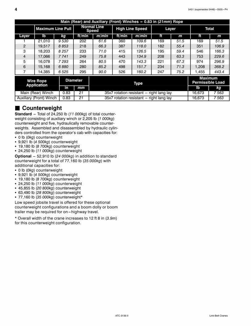
Main (Rear) and Auxiliary (Front) Winches --- 0.83 in (21mm) Rope
Maximum Line Pull Normal LineSpeed High Line Speed Layer Total
Layer lb kg ft/min m/min ft/min m/min ft m ft m1 21,010 9 530 202 61.6 360 109.6 169 51.5 169 51.52 19,517 8 853 218 66.3 387 118.0 182 55.4 351 106.93 18,203 8 257 233 71.0 415 126.5 195 59.4 546 166.34 17,066 7 741 249 75.8 443 134.9 208 63.3 753 229.65 16,078 7 293 264 80.5 470 143.3 221 67.3 974 296.96 15,168 6 880 280 85.2 498 151.7 234 71.3 1,208 368.27 14,385 6 525 295 90.0 526 160.2 247 75.2 1,455 443.4
Wire RopeApplication
DiameterType
MaximumPermissible Load
Application in mmType
lb kgMain (Rear) Winch 0.83 21 35x7 rotation resistant --- right lang lay 16,673 7 563Auxiliary (Front) Winch 0.83 21 35x7 rotation resistant --- right lang lay 16,673 7 563
J CounterweightStandard --- Total of 24,250 lb (11 000kg) of total counter-weight consisting of auxiliary winch or 2,205 lb (1 000kg)counterweight and five, hydraulically removable counter-weights. Assembled and disassembled by hydraulic cylin-ders controlled from the operator’s cab with capacities for:S 0 lb (0kg) counterweightS 9,921 lb (4 500kg) counterweightS 19,180 lb (8 700kg) counterweightS 24,250 lb (11 000kg) counterweightOptional --- 52,910 lb (24 000kg) in addition to standardcounterweight for a total of 77,160 lb (35 000kg) withadditional capacities for:S 0 lb (0kg) counterweightS 9,921 lb (4 500kg) counterweightS 19,180 lb (8 700kg) counterweightS 24,250 lb (11 000kg) counterweightS 45,855 lb (20 800kg) counterweightS 63,490 lb (28 800kg) counterweightS 77,160 lb (35 000kg) counterweight*Low speed jobsite travel is offered for these optionalcounterweight configurations and a boom dolly or boomtrailer may be required for on ---highway travel.
* Overall width of the crane increases to 12 ft 8 in (3.9m)for this counterweight configuration.

55451 (supersedes 5446)---0505---P4
ATC-3130 IILink-Belt Cranes
24,250 lb (11 000kg) 77,160 lb (35 000kg)
1
23
6
9
8
7
54
4
1
2
9
8
7
9 8 7 6 5 4 3 2* 1
CounterweightModules 2,425 lb
(1 100kg)tray
6,834 lb(3 100kg)piece
5,071 lb(2 300kg)piece
14,110 lb(6 400kg)2---piece
17,639 lb(8 000kg)piece
13,669 lb(6 200kg)2---piece
7,496 lb(3 400kg)piece
2,204 lb(1 000kg)top*
7,716 lb(3 500kg)piece
0 lb(0kg)
Sta da d
9,921 lb(4 500kg) X X X X
Standard19,180 lb(8 700kg) X X X X
CounterweightUsage
Configurations
24,250 lb(11 000kg) X X X X X
Configurations45,855 lb(20 800kg) X X X X X X X
Optional63,490 lb(28 800kg) X X X X X X X X77,160 lb(35 000kg) X X X X X X X X X
* Auxiliary winch replaces this counterweight for a two--drum configuration.
6 5451 (supersedes 5446)---0505---P4
ATC-3130 II Link-Belt Cranes
CarrierJ GeneralS 9 ft 9 in (3.0m) wide with 20.5R25 tiresS 25 ft 4 in (7.7m) wheelbase (centerline of first axle to cent-erline of fifth axle)
S Frame --- Box---type, torsion resistant, welded construc-tion made of high tensile steel. Equipped with front andrear towing and tie---down lugs, tow connections, andaccess ladders.
J OutriggersBoxes --- Two double box, front and rear welded to the car-rier frame
Beams and Jacks --- Four dual stage beams with ConfinedArea Lifting Capacities (CALC) provide selectable outriggerextensions of full and intermediate positions. Jacks withintegral check valves, hydraulically controlled from the op-erator’s cab and on both sides of carrier. Automatic level-ing.
Pontoons --- Four lightweight, stow’n go, 21.3 in (54.2cm)square nylon pontoons with a contact area of 455 in2(2 937.6cm2) can be stored for road travel under the outrig-ger boxes.
Main Jack Reaction --- 157,366 lb (700.0kN) force and 346psi (2 384.6kPa) ground bearing pressure
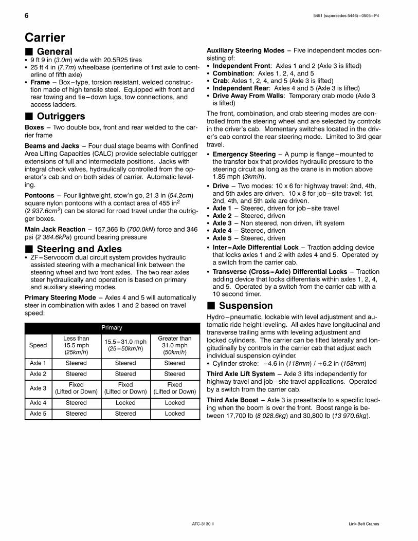
J Steering and AxlesS ZF---Servocom dual circuit system provides hydraulicassisted steering with a mechanical link between thesteering wheel and two front axles. The two rear axlessteer hydraulically and operation is based on primaryand auxiliary steering modes.
Primary Steering Mode --- Axles 4 and 5 will automaticallysteer in combination with axles 1 and 2 based on travelspeed:
Primary
SpeedLess than15.5 mph(25km/h)
15.5---31.0 mph(25---50km/h)
Greater than31.0 mph(50km/h)
Axle 1 Steered Steered Steered
Axle 2 Steered Steered Steered
Axle 3 Fixed(Lifted or Down)
Fixed(Lifted or Down)
Fixed(Lifted or Down)
Axle 4 Steered Locked Locked
Axle 5 Steered Steered Locked
Auxiliary Steering Modes --- Five independent modes con-sisting of:S Independent Front: Axles 1 and 2 (Axle 3 is lifted)S Combination: Axles 1, 2, 4, and 5S Crab: Axles 1, 2, 4, and 5 (Axle 3 is lifted)S Independent Rear: Axles 4 and 5 (Axle 3 is lifted)S Drive Away From Walls: Temporary crab mode (Axle 3is lifted)The front, combination, and crab steering modes are con-trolled from the steering wheel and are selected by controlsin the driver’s cab. Momentary switches located in the driv-er’s cab control the rear steering mode. Limited to 3rd geartravel.S Emergency Steering --- A pump is flange---mounted tothe transfer box that provides hydraulic pressure to thesteering circuit as long as the crane is in motion above1.85 mph (3km/h).
S Drive --- Two modes: 10 x 6 for highway travel: 2nd, 4th,and 5th axles are driven. 10 x 8 for job---site travel: 1st,2nd, 4th, and 5th axle are driven.
S Axle 1 --- Steered, driven for job---site travelS Axle 2 --- Steered, drivenS Axle 3 --- Non steered, non driven, lift systemS Axle 4 --- Steered, drivenS Axle 5 --- Steered, drivenS Inter---Axle Differential Lock --- Traction adding devicethat locks axles 1 and 2 with axles 4 and 5. Operated bya switch from the carrier cab.
S Transverse (Cross---Axle) Differential Locks --- Tractionadding device that locks differentials within axles 1, 2, 4,and 5. Operated by a switch from the carrier cab with a10 second timer.
J SuspensionHydro---pneumatic, lockable with level adjustment and au-tomatic ride height leveling. All axles have longitudinal andtransverse trailing arms with leveling adjustment andlocked cylinders. The carrier can be tilted laterally and lon-gitudinally by controls in the carrier cab that adjust eachindividual suspension cylinder.S Cylinder stroke: ---4.6 in (118mm) / +6.2 in (158mm)Third Axle Lift System --- Axle 3 lifts independently forhighway travel and job---site travel applications. Operatedby a switch from the carrier cab.
Third Axle Boost --- Axle 3 is presettable to a specific load-ing when the boom is over the front. Boost range is be-tween 17,700 lb (8 028.6kg) and 30,800 lb (13 970.6kg).
75451 (supersedes 5446)---0505---P4
ATC-3130 IILink-Belt Cranes
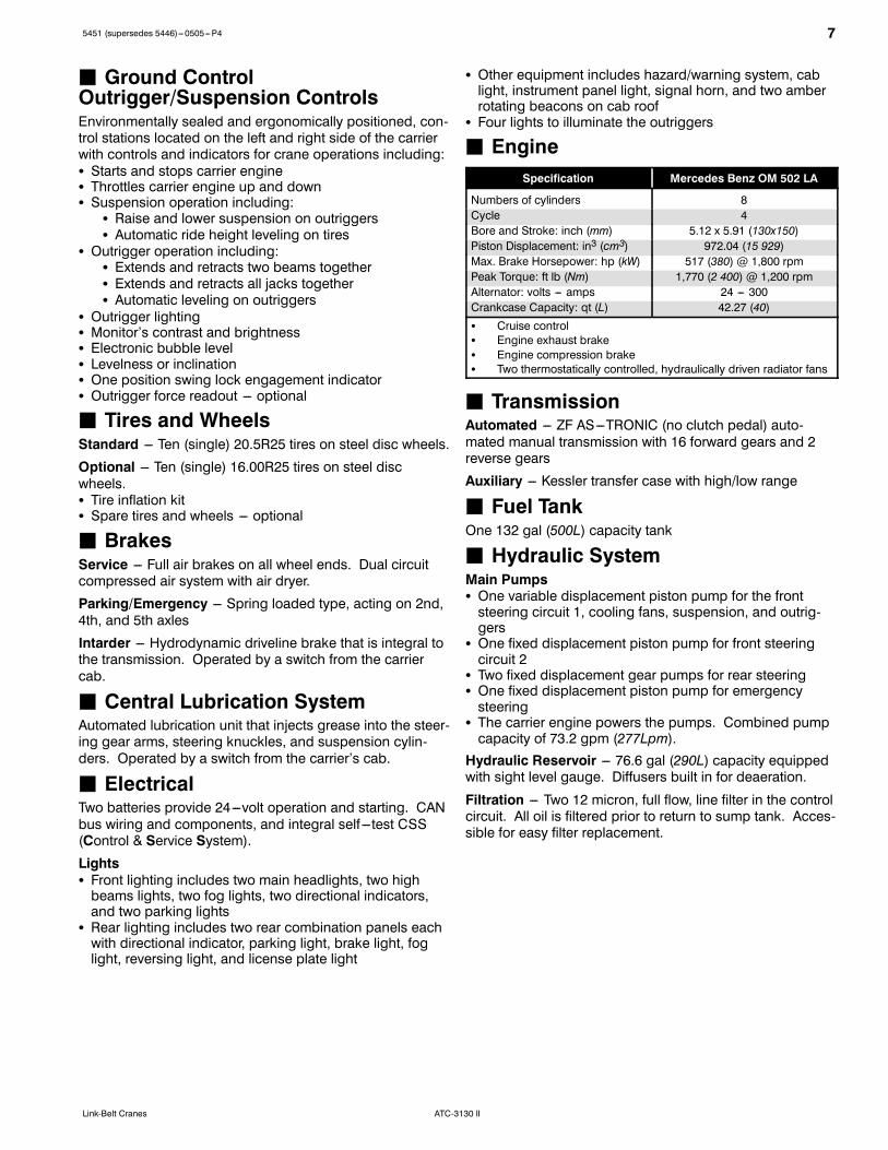
J Ground ControlOutrigger/Suspension ControlsEnvironmentally sealed and ergonomically positioned, con-trol stations located on the left and right side of the carrierwith controls and indicators for crane operations including:S Starts and stops carrier engineS Throttles carrier engine up and downS Suspension operation including:
S Raise and lower suspension on outriggersS Automatic ride height leveling on tires
S Outrigger operation including:S Extends and retracts two beams togetherS Extends and retracts all jacks togetherS Automatic leveling on outriggers
S Outrigger lightingS Monitor’s contrast and brightnessS Electronic bubble levelS Levelness or inclinationS One position swing lock engagement indicatorS Outrigger force readout --- optional
J Tires and WheelsStandard --- Ten (single) 20.5R25 tires on steel disc wheels.
Optional --- Ten (single) 16.00R25 tires on steel discwheels.S Tire inflation kitS Spare tires and wheels --- optional
J BrakesService --- Full air brakes on all wheel ends. Dual circuitcompressed air system with air dryer.
Parking/Emergency --- Spring loaded type, acting on 2nd,4th, and 5th axles
Intarder --- Hydrodynamic driveline brake that is integral tothe transmission. Operated by a switch from the carriercab.
J Central Lubrication SystemAutomated lubrication unit that injects grease into the steer-ing gear arms, steering knuckles, and suspension cylin-ders. Operated by a switch from the carrier’s cab.
J ElectricalTwo batteries provide 24---volt operation and starting. CANbus wiring and components, and integral self ---test CSS(Control & Service System).
LightsS Front lighting includes two main headlights, two highbeams lights, two fog lights, two directional indicators,and two parking lights
S Rear lighting includes two rear combination panels eachwith directional indicator, parking light, brake light, foglight, reversing light, and license plate light
S Other equipment includes hazard/warning system, cablight, instrument panel light, signal horn, and two amberrotating beacons on cab roof
S Four lights to illuminate the outriggers
J EngineSpecification Mercedes Benz OM 502 LA
Numbers of cylinders 8Cycle 4Bore and Stroke: inch (mm) 5.12 x 5.91 (130x150)Piston Displacement: in3 (cm3) 972.04 (15 929)Max. Brake Horsepower: hp (kW) 517 (380) @ 1,800 rpmPeak Torque: ft lb (Nm) 1,770 (2 400) @ 1,200 rpmAlternator: volts --- amps 24 --- 300Crankcase Capacity: qt (L) 42.27 (40)S Cruise controlS Engine exhaust brakeS Engine compression brakeS Two thermostatically controlled, hydraulically driven radiator fans
J TransmissionAutomated --- ZF AS---TRONIC (no clutch pedal) auto-mated manual transmission with 16 forward gears and 2reverse gears
Auxiliary --- Kessler transfer case with high/low range
J Fuel TankOne 132 gal (500L) capacity tank
J Hydraulic SystemMain PumpsS One variable displacement piston pump for the frontsteering circuit 1, cooling fans, suspension, and outrig-gers
S One fixed displacement piston pump for front steeringcircuit 2
S Two fixed displacement gear pumps for rear steeringS One fixed displacement piston pump for emergencysteering
S The carrier engine powers the pumps. Combined pumpcapacity of 73.2 gpm (277Lpm).Hydraulic Reservoir --- 76.6 gal (290L) capacity equippedwith sight level gauge. Diffusers built in for deaeration.
Filtration --- Two 12 micron, full flow, line filter in the controlcircuit. All oil is filtered prior to return to sump tank. Acces-sible for easy filter replacement.

8 5451 (supersedes 5446)---0505---P4
ATC-3130 II Link-Belt Cranes
J Cab and ControlsCab --- Fully enclosed, two person full width cab of com-posite structure with acoustical insulation. Equipped with:S Tinted and tempered glass windowsS Windshield wiper and washerS Slide side windows of hardened glassS Six way adjustable and air suspended driver and passen-ger seats with integrated three point safety belts and hea-drests
S Two heated and electrically adjustable rear---view mirrorsS One heated wide angle mirror and additional turn mirrorS Engine dependent warm---water heater with defrosternozzles for windshield and cab floor
S AM/FM radio with single disc CD playerS Adjustable sun visorS Dome lightS 12 volt and 24 volt connectionS Air conditioningS Fire extinguisherCab Instrumentation --- Ergonomically positioned analoginstrumentation for driving including:S Speedometer with odometerS Transmission mode, gear indication, and travel directionS Engine coolant temperatureS Fuel levelS Tachometer with hourmeterDash Mounted --- Controls and indicators for:S Battery main shutoffS Carrier throttle (0 to 1,200 rpm)S Carrier lightingS Auxiliary transmission high/low rangeS 10x8 drive, inter---axle lock, and transverse differentiallock
S Carrier control to operator’s cabS Suspension operation, automatic leveling, and lockS Cruise and intarder activationS Mirror heatingS Warning lampsS Engine/gearbox malfunction with audible alarmS Service and park brake indicationS Steering system malfunction with audible alarm
Cockpit Multi ---Vision (CMV) Display --- Ergonomicallypositioned on the driver’s dash panel, digital instrumenta-tion and indicators for crane operations including:S Front and rear air pressureS Air cleaner and hydraulic oil filter replacementS Low engine oil and coolantS Steering system malfunctionS Emergency steering activationS CAN---BUS diagnosticsS Sensor faultS Low voltageS Tachometer faultS Low fuelS Suspension lifted and locked
S Auxiliary transmission high/low rangeS Suspension leveledS High beam headlightsS Third axle liftedS Rear fog light activationS 10x8 drive, inter---axle lock, and transverse differentiallock
S One position swing lock engagementS Intarder activationS Axle oscillation activationS Central lubrication activationS Carrier control to operator’s cabS Boom raised out of the boom restS Display contrast and brightness readoutS Crane service diagnostics readoutsS Electronic bubble levelS Axle loadings readoutsS Steering modesCenter Console --- Controls and indicators for:S Heating and air conditioning controlsS Transmission gear shiftingS Auxiliary steering controlsS Rear axle locking switchS Mirror adjustmentsS Park brakeSteering Column --- Controls for:S Carrier ignitionS Warning hornS Turn indicatorsS High beam headlightsS Steer wheel adjustmentsS Cruise and intarder controlsS Windshield wipers and washersFoot Controls --- Controls for:S Carrier service brakesS Engine throttle
J Additional EquipmentStandard:S Pneumatic and electrical quick disconnect connectorsmounted on the rear bumper for boom dolly brakes andlights.
S Emergency function overridesS Aluminum full deck fenders and laddersS Hook block and ball bumper tie backsS Left and right side carrier storage boxesS Hook ball storageS Folding ladder (stowed under the carrier cab)S Handling slingsS Mud flapsS Tool box with toolsS Grease gunS First aid kitS Tire inflation systemS Battery jumper cables
95451 (supersedes 5446)---0505---P4
ATC-3130 IILink-Belt Cranes
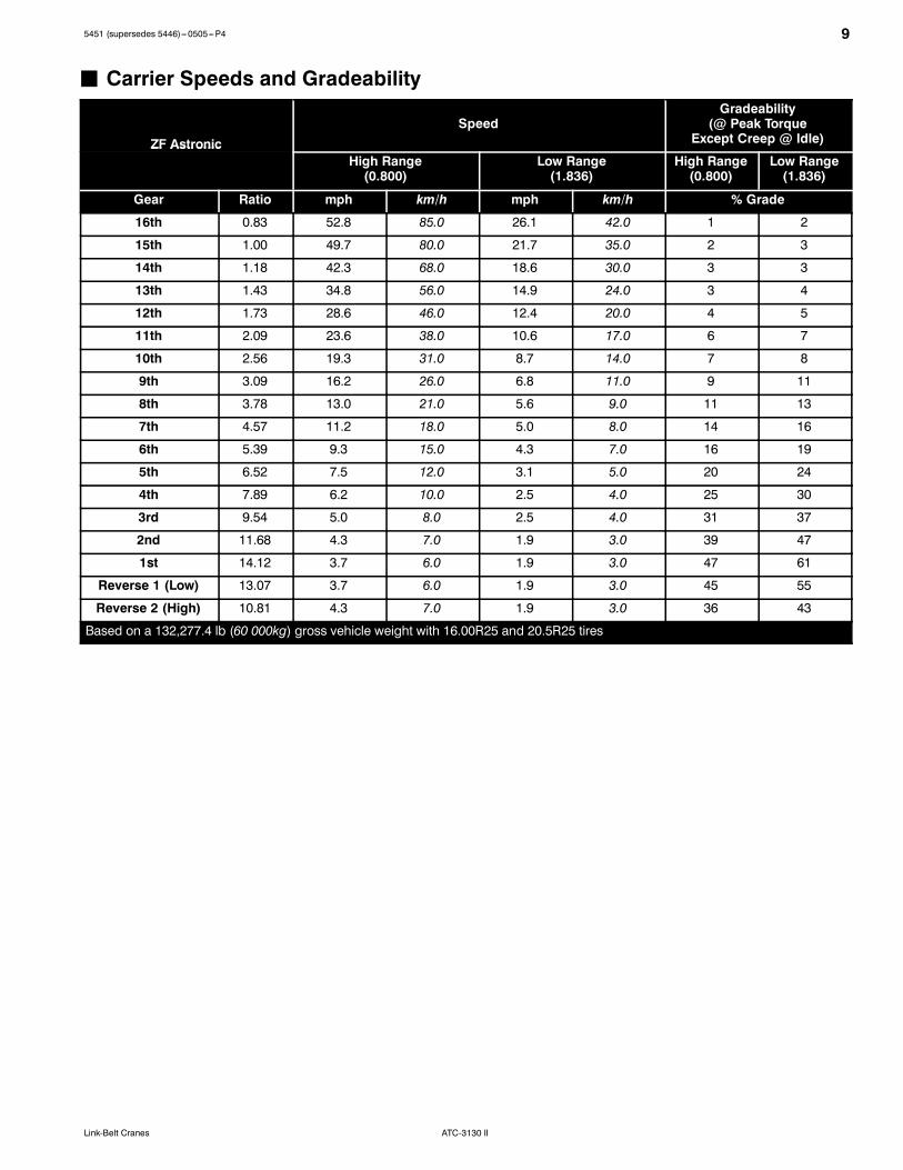
J Carrier Speeds and Gradeability
ZF AstronicSpeed
Gradeability(@ Peak Torque
Except Creep @ Idle)ZF AstronicHigh Range(0.800)
Low Range(1.836)
High Range(0.800)
Low Range(1.836)
Gear Ratio mph km/h mph km/h % Grade
16th 0.83 52.8 85.0 26.1 42.0 1 2
15th 1.00 49.7 80.0 21.7 35.0 2 3
14th 1.18 42.3 68.0 18.6 30.0 3 3
13th 1.43 34.8 56.0 14.9 24.0 3 4
12th 1.73 28.6 46.0 12.4 20.0 4 5
11th 2.09 23.6 38.0 10.6 17.0 6 7
10th 2.56 19.3 31.0 8.7 14.0 7 8
9th 3.09 16.2 26.0 6.8 11.0 9 11
8th 3.78 13.0 21.0 5.6 9.0 11 13
7th 4.57 11.2 18.0 5.0 8.0 14 16
6th 5.39 9.3 15.0 4.3 7.0 16 19
5th 6.52 7.5 12.0 3.1 5.0 20 24
4th 7.89 6.2 10.0 2.5 4.0 25 30
3rd 9.54 5.0 8.0 2.5 4.0 31 37
2nd 11.68 4.3 7.0 1.9 3.0 39 47
1st 14.12 3.7 6.0 1.9 3.0 47 61
Reverse 1 (Low) 13.07 3.7 6.0 1.9 3.0 45 55
Reverse 2 (High) 10.81 4.3 7.0 1.9 3.0 36 43
Based on a 132,277.4 lb (60 000kg) gross vehicle weight with 16.00R25 and 20.5R25 tires
10 5451 (supersedes 5446)---0505---P4
ATC-3130 II Link-Belt Cranes
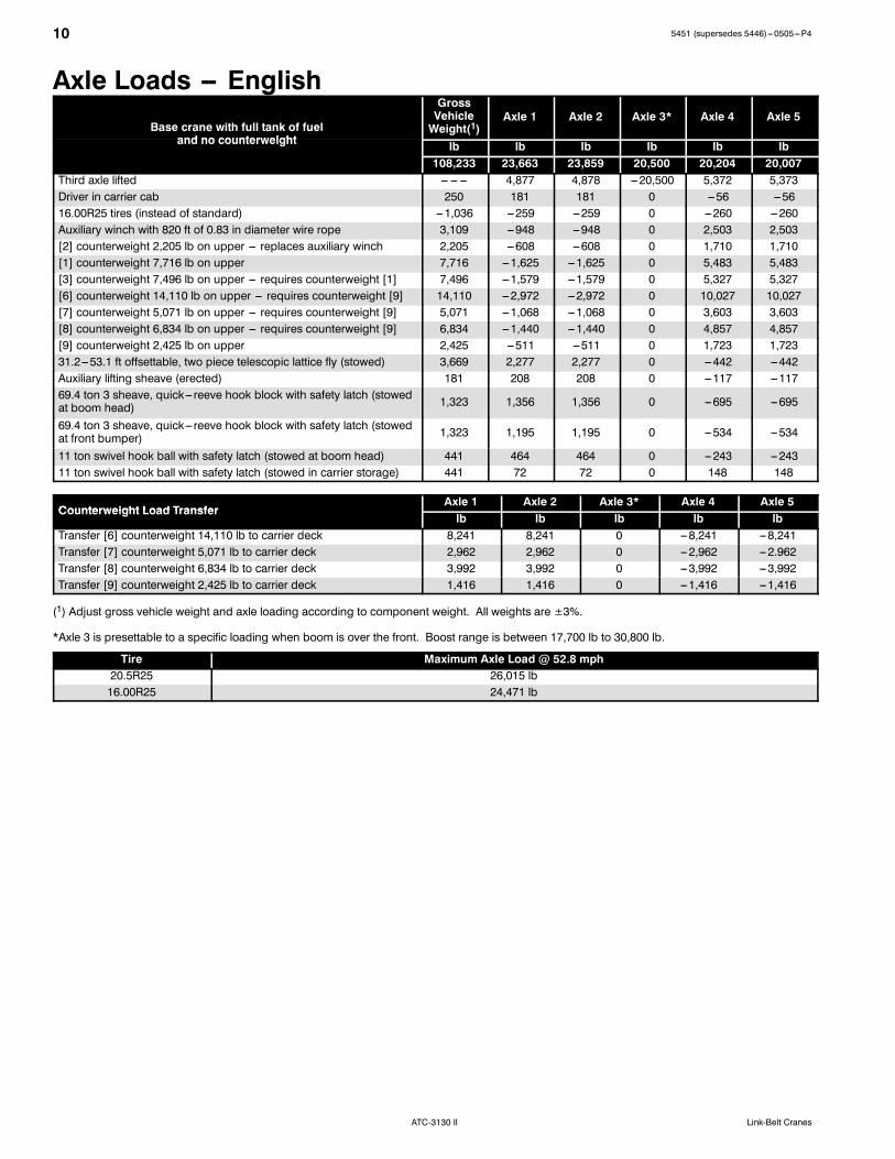
Axle Loads -- EnglishBase crane with full tank of fuel
and no counterweight
GrossVehicleWeight(1)
Axle 1 Axle 2 Axle 3* Axle 4 Axle 5
and no counterweight lb lb lb lb lb lb108,233 23,663 23,859 20,500 20,204 20,007
Third axle lifted --- --- --- 4,877 4,878 ---20,500 5,372 5,373Driver in carrier cab 250 181 181 0 ---56 ---5616.00R25 tires (instead of standard) ---1,036 ---259 ---259 0 ---260 ---260Auxiliary winch with 820 ft of 0.83 in diameter wire rope 3,109 ---948 ---948 0 2,503 2,503[2] counterweight 2,205 lb on upper --- replaces auxiliary winch 2,205 ---608 ---608 0 1,710 1,710[1] counterweight 7,716 lb on upper 7,716 ---1,625 ---1,625 0 5,483 5,483[3] counterweight 7,496 lb on upper --- requires counterweight [1] 7,496 ---1,579 ---1,579 0 5,327 5,327[6] counterweight 14,110 lb on upper --- requires counterweight [9] 14,110 ---2,972 ---2,972 0 10,027 10,027[7] counterweight 5,071 lb on upper --- requires counterweight [9] 5,071 ---1,068 ---1,068 0 3,603 3,603[8] counterweight 6,834 lb on upper --- requires counterweight [9] 6,834 ---1,440 ---1,440 0 4,857 4,857[9] counterweight 2,425 lb on upper 2,425 ---511 ---511 0 1,723 1,72331.2---53.1 ft offsettable, two piece telescopic lattice fly (stowed) 3,669 2,277 2,277 0 ---442 ---442Auxiliary lifting sheave (erected) 181 208 208 0 ---117 ---11769.4 ton 3 sheave, quick--- reeve hook block with safety latch (stowedat boom head) 1,323 1,356 1,356 0 ---695 ---695
69.4 ton 3 sheave, quick--- reeve hook block with safety latch (stowedat front bumper) 1,323 1,195 1,195 0 ---534 ---534
11 ton swivel hook ball with safety latch (stowed at boom head) 441 464 464 0 ---243 ---24311 ton swivel hook ball with safety latch (stowed in carrier storage) 441 72 72 0 148 148
Counterweight Load TransferAxle 1 Axle 2 Axle 3* Axle 4 Axle 5
Counterweight Load Transferlb lb lb lb lb
Transfer [6] counterweight 14,110 lb to carrier deck 8,241 8,241 0 ---8,241 ---8,241Transfer [7] counterweight 5,071 lb to carrier deck 2,962 2,962 0 ---2,962 ---2.962Transfer [8] counterweight 6,834 lb to carrier deck 3,992 3,992 0 ---3,992 ---3,992Transfer [9] counterweight 2,425 lb to carrier deck 1,416 1,416 0 ---1,416 ---1,416
(1) Adjust gross vehicle weight and axle loading according to component weight. All weights are ±3%.
*Axle 3 is presettable to a specific loading when boom is over the front. Boost range is between 17,700 lb to 30,800 lb.
Tire Maximum Axle Load @ 52.8 mph20.5R25 26,015 lb16.00R25 24,471 lb

115451 (supersedes 5446)---0505---P4
ATC-3130 IILink-Belt Cranes
Axle Loads -- MetricBase crane with full tank of fuel
and no counterweight
GrossVehicleWeight(1)
Axle 1 Axle 2 Axle 3* Axle 4 Axle 5
and no counterweight kg kg kg kg kg kg49 094 10 733 10 822 9 299 9 164 9 075
Third axle lifted --- --- --- 2 212 2 213 ---9 299 2 437 2 437Driver in carrier cab 113 82 82 0 ---25 ---2516.00R25 tires (instead of standard) ---470 ---117 ---117 0 ---118 ---118Auxiliary winch with 250m of 21mm diameter wire rope 1 410 ---430 ---430 0 1 135 1 135[2] counterweight 1 000kg on upper --- replaces auxiliary winch 1 000 ---276 ---276 0 776 776[1] counterweight 3 500kg on upper 3 500 ---737 ---737 0 2 487 2 487[3] counterweight 3 400kg on upper --- requires counterweight [1] 3 400 ---716 ---716 0 2 416 2 416[6] counterweight 6 400kg on upper --- requires counterweight [9] 6 400 ---1 348 ---1 348 0 4 548 4 548[7] counterweight 2 300kg on upper --- requires counterweight [9] 2 300 ---484 ---484 0 1 634 1 634[8] counterweight 3 100kg on upper --- requires counterweight [9] 3 100 ---653 ---653 0 2 203 2 203[9] counterweight 1 100kg on upper 1 100 411 411 0 139 1399.5---16.2m offsettable, two piece telescopic lattice fly (stowed) 1 664 1 033 1 033 0 ---200 ---200Auxiliary lifting sheave (erected) 82 94 94 0 ---53 ---5363 mt 3 sheave, quick--- reeve hook block with safety latch (stowed atboom head) 600 615 615 0 ---315 ---315
63 mt 3 sheave, quick--- reeve hook block with safety latch (stowed atfront bumper) 600 642 642 0 ---242 ---242
10 mt swivel hook ball with safety latch (stowed at boom head) 200 210 210 0 ---110 ---11010 mt swivel hook ball with safety latch (stowed in carrier storage) 200 32 32 0 67 67
Counterweight Load TransferAxle 1 Axle 2 Axle 3* Axle 4 Axle 5
Counterweight Load Transferkg kg kg kg kg
Transfer [6] counterweight 6 400kg to carrier deck 3 738 3 738 0 ---3 738 ---3 738Transfer [7] counterweight 2 300kg to carrier deck 1 344 1 344 0 ---1 344 ---1 344Transfer [8] counterweight 3 100kg to carrier deck 1 811 1 811 0 ---1 811 ---1 811Transfer [9] counterweight 1 100kg to carrier deck 642 642 0 ---642 ---642
(1) Adjust gross vehicle weight and axle loading according to component weight. All weights are ±3%.
*Axle 3 is presettable to a specific loading when boom is over the front. Boost range is between 8 028.6kg to 13 970.6kg.
Tire Maximum Axle Load @ 85km/h20.5R25 11 800kg16.00R25 11 100kg
12 5451 (supersedes 5446)---0505---P4
ATC-3130 II Link-Belt Cranes
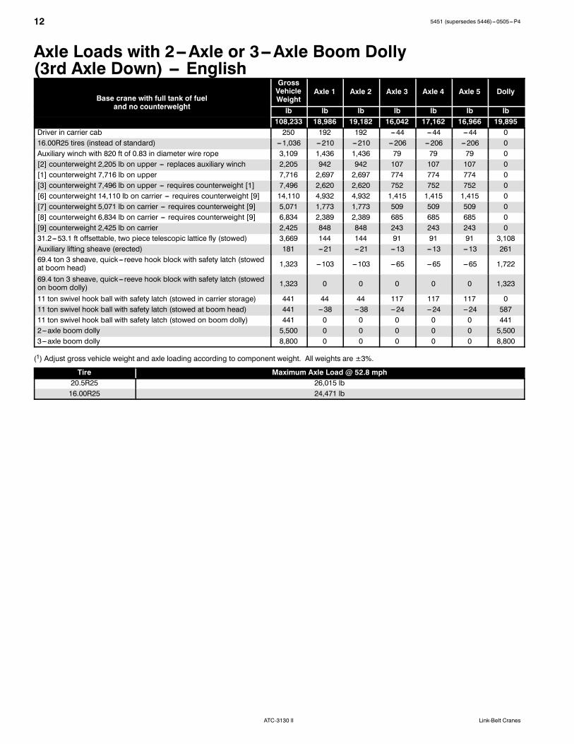
Axle Loads with 2--Axle or 3--Axle Boom Dolly(3rd Axle Down) -- English
Base crane with full tank of fueland no counterweight
GrossVehicleWeight
Axle 1 Axle 2 Axle 3 Axle 4 Axle 5 Dolly
and no counterweight lb lb lb lb lb lb lb108,233 18,986 19,182 16,042 17,162 16,966 19,895
Driver in carrier cab 250 192 192 ---44 ---44 ---44 016.00R25 tires (instead of standard) ---1,036 ---210 ---210 ---206 ---206 ---206 0Auxiliary winch with 820 ft of 0.83 in diameter wire rope 3,109 1,436 1,436 79 79 79 0[2] counterweight 2,205 lb on upper --- replaces auxiliary winch 2,205 942 942 107 107 107 0[1] counterweight 7,716 lb on upper 7,716 2,697 2,697 774 774 774 0[3] counterweight 7,496 lb on upper --- requires counterweight [1] 7,496 2,620 2,620 752 752 752 0[6] counterweight 14,110 lb on carrier --- requires counterweight [9] 14,110 4,932 4,932 1,415 1,415 1,415 0[7] counterweight 5,071 lb on carrier --- requires counterweight [9] 5,071 1,773 1,773 509 509 509 0[8] counterweight 6,834 lb on carrier --- requires counterweight [9] 6,834 2,389 2,389 685 685 685 0[9] counterweight 2,425 lb on carrier 2,425 848 848 243 243 243 031.2---53.1 ft offsettable, two piece telescopic lattice fly (stowed) 3,669 144 144 91 91 91 3,108Auxiliary lifting sheave (erected) 181 ---21 ---21 ---13 ---13 ---13 26169.4 ton 3 sheave, quick--- reeve hook block with safety latch (stowedat boom head) 1,323 ---103 ---103 ---65 ---65 ---65 1,722
69.4 ton 3 sheave, quick--- reeve hook block with safety latch (stowedon boom dolly) 1,323 0 0 0 0 0 1,323
11 ton swivel hook ball with safety latch (stowed in carrier storage) 441 44 44 117 117 117 011 ton swivel hook ball with safety latch (stowed at boom head) 441 ---38 ---38 ---24 ---24 ---24 58711 ton swivel hook ball with safety latch (stowed on boom dolly) 441 0 0 0 0 0 4412---axle boom dolly 5,500 0 0 0 0 0 5,5003---axle boom dolly 8,800 0 0 0 0 0 8,800
(1) Adjust gross vehicle weight and axle loading according to component weight. All weights are ±3%.
Tire Maximum Axle Load @ 52.8 mph20.5R25 26,015 lb16.00R25 24,471 lb
135451 (supersedes 5446)---0505---P4
ATC-3130 IILink-Belt Cranes
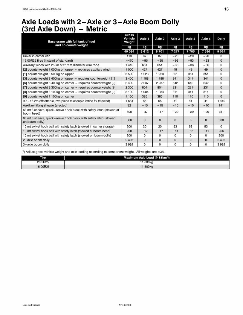
Axle Loads with 2--Axle or 3--Axle Boom Dolly(3rd Axle Down) -- Metric
Base crane with full tank of fueland no counterweight
GrossVehicleWeight
Axle 1 Axle 2 Axle 3 Axle 4 Axle 5 Dolly
and no counterweight kg kg kg kg kg kg kg49 094 8 612 8 701 7 277 7 785 7 696 9 024
Driver in carrier cab 113 87 87 ---20 ---20 ---20 016.00R25 tires (instead of standard) ---470 ---95 ---95 ---93 ---93 ---93 0Auxiliary winch with 250m of 21mm diameter wire rope 1 410 651 651 ---36 ---36 ---36 0[2] counterweight 1 000kg on upper --- replaces auxiliary winch 1 000 427 427 49 49 49 0[1] counterweight 3 500kg on upper 3 500 1 223 1 223 351 351 351 0[3] counterweight 3 400kg on upper --- requires counterweight [1] 3 400 1 188 1 188 341 341 341 0[6] counterweight 6 400kg on carrier --- requires counterweight [9] 6 400 2 237 2 237 642 642 642 0[7] counterweight 2 300kg on carrier --- requires counterweight [9] 2 300 804 804 231 231 231 0[8] counterweight 3 100kg on carrier --- requires counterweight [9] 3 100 1 084 1 084 311 311 311 0[9] counterweight 1 100kg on carrier 1 100 385 385 110 110 110 09.5---16.2m offsettable, two piece telescopic lattice fly (stowed) 1 664 65 65 41 41 41 1 410Auxiliary lifting sheave (erected) 82 ---15 ---15 ---10 ---10 ---10 14163 mt 3 sheave, quick--- reeve hook block with safety latch (stowed atboom head) 600 ---47 ---47 ---29 ---29 ---29 781
63 mt 3 sheave, quick--- reeve hook block with safety latch (stowedon boom dolly) 600 0 0 0 0 0 600
10 mt swivel hook ball with safety latch (stowed in carrier storage) 200 20 20 53 53 53 010 mt swivel hook ball with safety latch (stowed at boom head) 200 ---17 ---17 ---11 ---11 ---11 26610 mt swivel hook ball with safety latch (stowed on boom dolly) 200 0 0 0 0 0 2002---axle boom dolly 2 495 0 0 0 0 0 2 4953---axle boom dolly 3 992 0 0 0 0 0 3 992
(1) Adjust gross vehicle weight and axle loading according to component weight. All weights are ±3%.
Tire Maximum Axle Load @ 85km/h20.5R25 11 800kg16.00R25 11 100kg
14 5451 (supersedes 5446)---0505---P4
ATC-3130 II Link-Belt Cranes
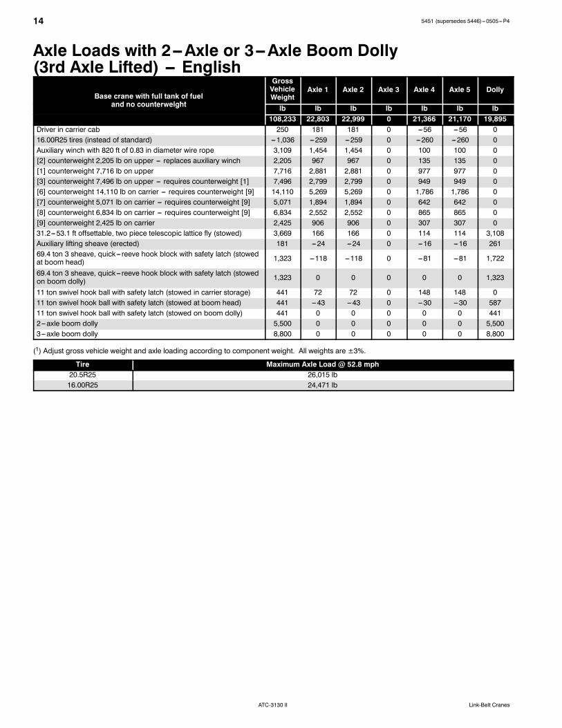
Axle Loads with 2--Axle or 3--Axle Boom Dolly(3rd Axle Lifted) -- English
Base crane with full tank of fueland no counterweight
GrossVehicleWeight
Axle 1 Axle 2 Axle 3 Axle 4 Axle 5 Dolly
and no counterweight lb lb lb lb lb lb lb108,233 22,803 22,999 0 21,366 21,170 19,895
Driver in carrier cab 250 181 181 0 ---56 ---56 016.00R25 tires (instead of standard) ---1,036 ---259 ---259 0 ---260 ---260 0Auxiliary winch with 820 ft of 0.83 in diameter wire rope 3,109 1,454 1,454 0 100 100 0[2] counterweight 2,205 lb on upper --- replaces auxiliary winch 2,205 967 967 0 135 135 0[1] counterweight 7,716 lb on upper 7,716 2,881 2,881 0 977 977 0[3] counterweight 7,496 lb on upper --- requires counterweight [1] 7,496 2,799 2,799 0 949 949 0[6] counterweight 14,110 lb on carrier --- requires counterweight [9] 14,110 5,269 5,269 0 1,786 1,786 0[7] counterweight 5,071 lb on carrier --- requires counterweight [9] 5,071 1,894 1,894 0 642 642 0[8] counterweight 6,834 lb on carrier --- requires counterweight [9] 6,834 2,552 2,552 0 865 865 0[9] counterweight 2,425 lb on carrier 2,425 906 906 0 307 307 031.2---53.1 ft offsettable, two piece telescopic lattice fly (stowed) 3,669 166 166 0 114 114 3,108Auxiliary lifting sheave (erected) 181 ---24 ---24 0 ---16 ---16 26169.4 ton 3 sheave, quick--- reeve hook block with safety latch (stowedat boom head) 1,323 ---118 ---118 0 ---81 ---81 1,722
69.4 ton 3 sheave, quick--- reeve hook block with safety latch (stowedon boom dolly) 1,323 0 0 0 0 0 1,323
11 ton swivel hook ball with safety latch (stowed in carrier storage) 441 72 72 0 148 148 011 ton swivel hook ball with safety latch (stowed at boom head) 441 ---43 ---43 0 ---30 ---30 58711 ton swivel hook ball with safety latch (stowed on boom dolly) 441 0 0 0 0 0 4412---axle boom dolly 5,500 0 0 0 0 0 5,5003---axle boom dolly 8,800 0 0 0 0 0 8,800
(1) Adjust gross vehicle weight and axle loading according to component weight. All weights are ±3%.
Tire Maximum Axle Load @ 52.8 mph20.5R25 26,015 lb16.00R25 24,471 lb
155451 (supersedes 5446)---0505---P4
ATC-3130 IILink-Belt Cranes
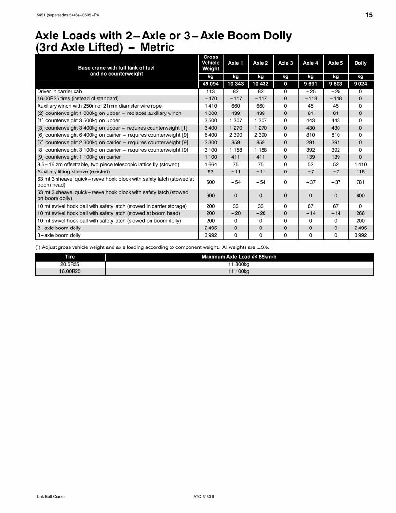
Axle Loads with 2--Axle or 3--Axle Boom Dolly(3rd Axle Lifted) -- Metric
Base crane with full tank of fueland no counterweight
GrossVehicleWeight
Axle 1 Axle 2 Axle 3 Axle 4 Axle 5 Dolly
and no counterweight kg kg kg kg kg kg kg49 094 10 343 10 432 0 9 691 9 603 9 024
Driver in carrier cab 113 82 82 0 ---25 ---25 016.00R25 tires (instead of standard) ---470 ---117 ---117 0 ---118 ---118 0Auxiliary winch with 250m of 21mm diameter wire rope 1 410 660 660 0 45 45 0[2] counterweight 1 000kg on upper --- replaces auxiliary winch 1 000 439 439 0 61 61 0[1] counterweight 3 500kg on upper 3 500 1 307 1 307 0 443 443 0[3] counterweight 3 400kg on upper --- requires counterweight [1] 3 400 1 270 1 270 0 430 430 0[6] counterweight 6 400kg on carrier --- requires counterweight [9] 6 400 2 390 2 390 0 810 810 0[7] counterweight 2 300kg on carrier --- requires counterweight [9] 2 300 859 859 0 291 291 0[8] counterweight 3 100kg on carrier --- requires counterweight [9] 3 100 1 158 1 158 0 392 392 0[9] counterweight 1 100kg on carrier 1 100 411 411 0 139 139 09.5---16.2m offsettable, two piece telescopic lattice fly (stowed) 1 664 75 75 0 52 52 1 410Auxiliary lifting sheave (erected) 82 ---11 ---11 0 ---7 ---7 11863 mt 3 sheave, quick--- reeve hook block with safety latch (stowed atboom head) 600 ---54 ---54 0 ---37 ---37 781
63 mt 3 sheave, quick--- reeve hook block with safety latch (stowedon boom dolly) 600 0 0 0 0 0 600
10 mt swivel hook ball with safety latch (stowed in carrier storage) 200 33 33 0 67 67 010 mt swivel hook ball with safety latch (stowed at boom head) 200 ---20 ---20 0 ---14 ---14 26610 mt swivel hook ball with safety latch (stowed on boom dolly) 200 0 0 0 0 0 2002---axle boom dolly 2 495 0 0 0 0 0 2 4953---axle boom dolly 3 992 0 0 0 0 0 3 992
(1) Adjust gross vehicle weight and axle loading according to component weight. All weights are ±3%.
Tire Maximum Axle Load @ 85km/h20.5R25 11 800kg16.00R25 11 100kg
16 5451 (supersedes 5446)---0505---P4
ATC-3130 II Link-Belt Cranes
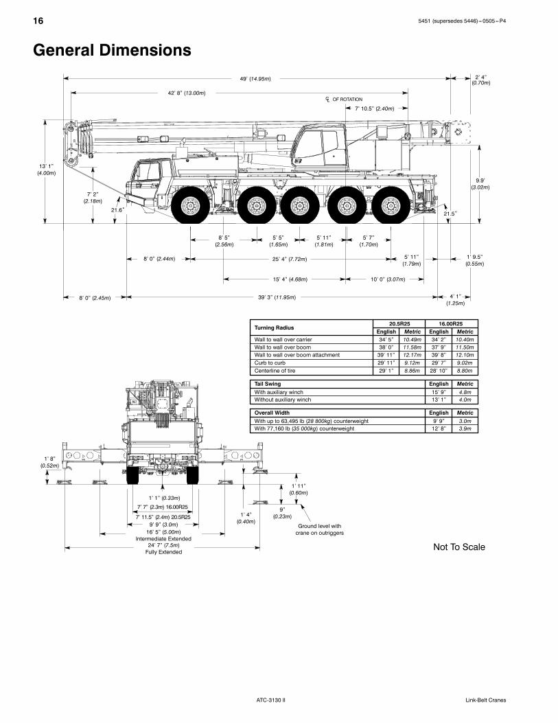
General Dimensions
7’ 7” (2.3m) 16.00R25
16’ 5” (5.00m)Intermediate Extended
24’ 7” (7.5m)Fully Extended
9’ 9” (3.0m)
1’ 1” (0.33m)
Ground level withcrane on outriggers
1’ 8”(0.52m)
1’ 11”(0.60m)
1’ 4”(0.40m)
9”(0.23m)
4’ 1”(1.25m)
Not To Scale
English MetricWall to wall over carrier 34’ 2” 10.40mWall to wall over boom 37’ 9” 11.50mWall to wall over boom attachment 39’ 8” 12.10mCurb to curb 29’ 7” 9.02mCenterline of tire 28’ 10” 8.80m
Tail Swing English MetricWith auxiliary winch 15’ 9” 4.8mWithout auxiliary winch 13’ 1” 4.0m
49’ (14.95m)
42’ 8” (13.00m)
7’ 10.5” (2.40m)
39’ 3” (11.95m)
5’ 7”(1.70m)
5’ 11”(1.81m)
5’ 5”(1.65m)
8’ 0” (2.44m)
13’ 1”(4.00m)
8’ 0” (2.45m)
25’ 4” (7.72m)
21.5˚21.6˚
9.9’(3.02m)
2’ 4”(0.70m)
5’ 11”(1.79m)
1’ 9.5”(0.55m)
8’ 5”(2.56m)
15’ 4” (4.68m) 10’ 0” (3.07m)
English Metric34’ 5” 10.49m38’ 0” 11.58m39’ 11” 12.17m29’ 11” 9.12m29’ 1” 8.86m
Turning Radius16.00R2520.5R25
CL OF ROTATION
Overall Width English MetricWith up to 63,495 lb (28 800kg) counterweight 9’ 9” 3.0mWith 77,160 lb (35 000kg) counterweight 12’ 8” 3.9m
7’ 2”(2.18m)
7’ 11.5” (2.4m) 20.5R25
175451 (supersedes 5446)---0505---P4
ATC-3130 IILink-Belt Cranes
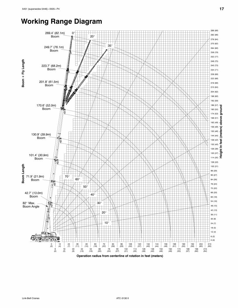
Working Range Diagram
Operation radius from centerline of rotation in feet (meters)
0_
42.7’ (13.0m)Boom
71.9’ (21.9m)Boom
101.4’ (30.9m)Boom
130.9’ (39.9m)Boom
170.6’ (52.0m)Boom
201.8’ (61.5m)Boom
223.7’ (68.2m)Boom
249.7’ (76.1m)Boom
269.4’ (82.1m)Boom
HeightInfeet(meters)aboveground
82_ Max.Boom Angle
20_
35_
10_
20_
30_
40_
50_
60_70_
6 (2)
0 (0)
12 (4)
18 (5)
24 (7)
30 (9)
36 (11)
42 (13)
48 (15)
54 (16)
60 (18)
66 (20)
72 (22)
78 (24)
84 (26)
90 (27)
96 (29)
102 (31)
108 (33)
114 (35)
120 (37)
126 (38)
132 (40)
138 (42)
144 (44)
150 (46)
156 (48)
162 (49)
168 (51)
174 (53)
180 (55)
186 (57)
192 (59)
198 (60)
204 (62)
210 (64)
216 (66)
222 (68)
228 (69)
234 (71)
240 (73)
246 (75)
252 (77)
258 (79)
264 (80)
270 (82)
276 (84)
282 (86)
288 (88)
0(0)
6(2)
12(4)
18(5)
24(7)
30(9)
36(11)
42(13)
48(15)
54(16)
60(18)
66(20)
72(22)
78(24)
84(26)
90(27)
96(29)
102(31)
108(33)
114(35)
120(37)
126(38)
132(40)
138(42)
144(44)
150(46)
156(48)
162(49)
168(51)
174(53)
180(55)
186(57)
192(59)
198(60)
204(62)
210(64)
213(65)
BoomLength
Boom+FlyLength

18 5451 (supersedes 5446)---0505---P4
ATC-3130 II Link-Belt Cranes
Boom Extend Modes
Base Tele I Tele II Tele III Tele IV
Boom Length Sections Lengthft m Tele I Tele II Tele III Tele IV170.6 52.0 100% 100% 100% 100%160.4 48.9 92% 92% 92% 92%
145 7 44 446% 92% 92% 92%
145.7 44.492% 92% 92% 46%0% 92% 92% 92%
130.9 39.9 46% 46% 92% 92%130.9 39.992% 92% 92% 0%0% 46% 92% 92%
116.1 35.4 46% 46% 46% 92%116.1 35.492% 92% 46% 0%0% 0% 92% 92%
101 4 30 90% 46% 46% 92%
101.4 30.946% 46% 46% 46%92% 46% 46% 0%0% 0% 46% 92%
86 6 26 40% 46% 46% 46%
86.6 26.446% 46% 46% 0%92% 46% 0% 0%0% 0% 0% 92%
71 9 21 90% 0% 46% 46%
71.9 21.90% 46% 46% 0%92% 0% 0% 0%0% 0% 0% 46%
57.1 17.4 0% 0% 46% 0%57.1 17.446% 0% 0% 0%
42.7 13.0 0% 0% 0% 0%
195451 (supersedes 5446)---0505---P4
ATC-3130 IILink-Belt Cranes
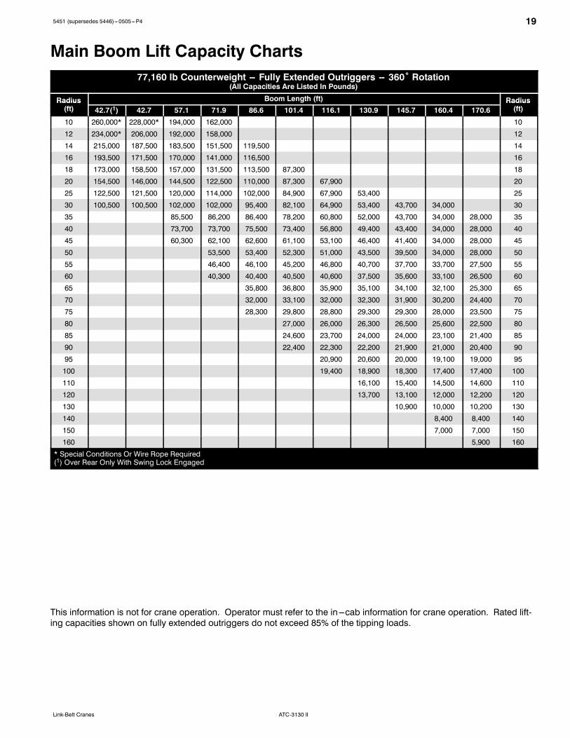
Main Boom Lift Capacity Charts77,160 lb Counterweight -- Fully Extended Outriggers -- 360˚ Rotation
(All Capacities Are Listed In Pounds)
Radius Boom Length (ft) RadiusRadius(ft) 42.7(1) 42.7 57.1 71.9 86.6 101.4 116.1 130.9 145.7 160.4 170.6
Radius(ft)
10 260,000* 228,000* 194,000 162,000 10
12 234,000* 206,000 192,000 158,000 12
14 215,000 187,500 183,500 151,500 119,500 14
16 193,500 171,500 170,000 141,000 116,500 16
18 173,000 158,500 157,000 131,500 113,500 87,300 18
20 154,500 146,000 144,500 122,500 110,000 87,300 67,900 20
25 122,500 121,500 120,000 114,000 102,000 84,900 67,900 53,400 25
30 100,500 100,500 102,000 102,000 95,400 82,100 64,900 53,400 43,700 34,000 30
35 85,500 86,200 86,400 78,200 60,800 52,000 43,700 34,000 28,000 35
40 73,700 73,700 75,500 73,400 56,800 49,400 43,400 34,000 28,000 40
45 60,300 62,100 62,600 61,100 53,100 46,400 41,400 34,000 28,000 45
50 53,500 53,400 52,300 51,000 43,500 39,500 34,000 28,000 50
55 46,400 46,100 45,200 46,800 40,700 37,700 33,700 27,500 55
60 40,300 40,400 40,500 40,600 37,500 35,600 33,100 26,500 60
65 35,800 36,800 35,900 35,100 34,100 32,100 25,300 65
70 32,000 33,100 32,000 32,300 31,900 30,200 24,400 70
75 28,300 29,800 28,800 29,300 29,300 28,000 23,500 75
80 27,000 26,000 26,300 26,500 25,600 22,500 80
85 24,600 23,700 24,000 24,000 23,100 21,400 85
90 22,400 22,300 22,200 21,900 21,000 20,400 90
95 20,900 20,600 20,000 19,100 19,000 95
100 19,400 18,900 18,300 17,400 17,400 100
110 16,100 15,400 14,500 14,600 110
120 13,700 13,100 12,000 12,200 120
130 10,900 10,000 10,200 130
140 8,400 8,400 140
150 7,000 7,000 150
160 5,900 160
* Special Conditions Or Wire Rope Required(1) Over Rear Only With Swing Lock Engaged
This information is not for crane operation. Operator must refer to the in---cab information for crane operation. Rated lift-ing capacities shown on fully extended outriggers do not exceed 85% of the tipping loads.

20 5451 (supersedes 5446)---0505---P4
ATC-3130 II Link-Belt Cranes
63,490 lb Counterweight -- Fully Extended Outriggers -- 360˚ Rotation(All Capacities Are Listed In Pounds)
Radius Boom Length (ft) RadiusRadius(ft) 42.7(1) 42.7 57.1 71.9 86.6 101.4 116.1 130.9 145.7 160.4 170.6
Radius(ft)
10 260,000* 228,000* 194,000 162,000 10
12 234,000* 205,500 192,000 158,000 12
14 211,500 187,000 183,000 151,500 119,500 14
16 187,000 171,000 169,500 141,000 116,500 16
18 167,000 158,000 156,500 131,500 113,500 87,300 18
20 149,000 145,500 144,000 122,500 110,000 87,300 67,900 20
25 118,000 118,000 116,000 113,500 102,000 84,900 67,900 53,400 25
30 96,700 96,700 98,300 98,300 94,900 82,100 64,900 53,400 43,700 34,000 30
35 80,200 81,300 81,800 78,200 60,800 52,000 43,700 34,000 28,000 35
40 65,200 67,800 67,600 66,300 56,800 49,400 43,400 34,000 28,000 40
45 55,200 56,900 56,700 55,400 53,100 46,400 41,400 34,000 28,000 45
50 48,700 48,500 47,700 47,900 42,800 39,500 34,000 28,000 50
55 42,100 41,900 42,900 42,100 38,600 37,200 33,700 27,500 55
60 36,400 36,400 37,800 36,700 36,000 35,600 33,100 26,500 60
65 32,100 33,400 32,300 32,600 32,300 31,500 25,300 65
70 29,200 30,100 28,900 29,400 29,200 28,400 24,400 70
75 26,500 27,000 26,600 26,700 26,200 25,300 23,500 75
80 24,300 24,800 24,100 23,500 22,600 22,100 80
85 22,000 22,400 21,700 21,300 20,400 20,600 85
90 20,100 20,500 19,900 19,400 18,500 18,600 90
95 18,800 18,200 17,700 16,700 16,900 95
100 17,200 16,700 16,100 15,000 15,400 100
110 14,000 13,400 12,500 12,500 110
120 11,700 11,100 10,200 10,200 120
130 9,200 8,200 8,400 130
140 6,800 6,800 140
150 5,400 5,400 150
160 4,400 160
* Special Conditions Or Wire Rope Required(1) Over Rear Only With Swing Lock Engaged
This information is not for crane operation. Operator must refer to the in---cab information for crane operation. Rated lift-ing capacities shown on fully extended outriggers do not exceed 85% of the tipping loads.
215451 (supersedes 5446)---0505---P4
ATC-3130 IILink-Belt Cranes
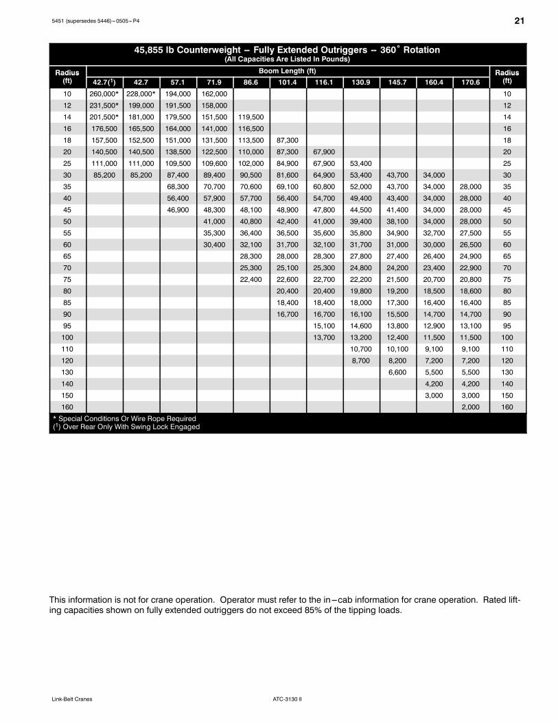
45,855 lb Counterweight -- Fully Extended Outriggers -- 360˚ Rotation(All Capacities Are Listed In Pounds)
Radius Boom Length (ft) RadiusRadius(ft) 42.7(1) 42.7 57.1 71.9 86.6 101.4 116.1 130.9 145.7 160.4 170.6
Radius(ft)
10 260,000* 228,000* 194,000 162,000 10
12 231,500* 199,000 191,500 158,000 12
14 201,500* 181,000 179,500 151,500 119,500 14
16 176,500 165,500 164,000 141,000 116,500 16
18 157,500 152,500 151,000 131,500 113,500 87,300 18
20 140,500 140,500 138,500 122,500 110,000 87,300 67,900 20
25 111,000 111,000 109,500 109,600 102,000 84,900 67,900 53,400 25
30 85,200 85,200 87,400 89,400 90,500 81,600 64,900 53,400 43,700 34,000 30
35 68,300 70,700 70,600 69,100 60,800 52,000 43,700 34,000 28,000 35
40 56,400 57,900 57,700 56,400 54,700 49,400 43,400 34,000 28,000 40
45 46,900 48,300 48,100 48,900 47,800 44,500 41,400 34,000 28,000 45
50 41,000 40,800 42,400 41,000 39,400 38,100 34,000 28,000 50
55 35,300 36,400 36,500 35,600 35,800 34,900 32,700 27,500 55
60 30,400 32,100 31,700 32,100 31,700 31,000 30,000 26,500 60
65 28,300 28,000 28,300 27,800 27,400 26,400 24,900 65
70 25,300 25,100 25,300 24,800 24,200 23,400 22,900 70
75 22,400 22,600 22,700 22,200 21,500 20,700 20,800 75
80 20,400 20,400 19,800 19,200 18,500 18,600 80
85 18,400 18,400 18,000 17,300 16,400 16,400 85
90 16,700 16,700 16,100 15,500 14,700 14,700 90
95 15,100 14,600 13,800 12,900 13,100 95
100 13,700 13,200 12,400 11,500 11,500 100
110 10,700 10,100 9,100 9,100 110
120 8,700 8,200 7,200 7,200 120
130 6,600 5,500 5,500 130
140 4,200 4,200 140
150 3,000 3,000 150
160 2,000 160
* Special Conditions Or Wire Rope Required(1) Over Rear Only With Swing Lock Engaged
This information is not for crane operation. Operator must refer to the in---cab information for crane operation. Rated lift-ing capacities shown on fully extended outriggers do not exceed 85% of the tipping loads.

22 5451 (supersedes 5446)---0505---P4
ATC-3130 II Link-Belt Cranes
24,250 lb Counterweight -- Fully Extended Outriggers -- 360˚ Rotation(All Capacities Are Listed In Pounds)
Radius Boom Length (ft) RadiusRadius(ft) 42.7(1) 42.7 57.1 71.9 86.6 101.4 116.1 130.9 145.7 160.4 170.6
Radius(ft)
10 260,000* 228,000* 194,000 162,000 10
12 217,000* 198,000 191,000 158,000 12
14 187,000 179,500 178,500 151,500 119,500 14
16 163,500 162,500 160,500 141,000 116,500 16
18 146,000 146,000 144,000 131,500 113,500 87,300 18
20 130,000 130,000 128,000 122,500 110,000 87,300 67,900 20
25 95,300 95,300 97,400 97,700 93,600 84,900 67,900 53,400 25
30 67,300 67,300 70,700 72,400 72,100 70,700 64,200 53,400 43,700 34,000 30
35 54,800 56,300 56,100 56,400 55,000 50,800 43,700 34,000 28,000 35
40 44,200 45,700 46,900 47,100 45,700 42,800 42,800 34,000 28,000 40
45 36,500 37,800 39,300 39,200 38,800 38,200 36,900 34,000 28,000 45
50 32,200 33,400 33,200 33,500 32,800 32,100 30,400 27,600 50
55 27,200 28,500 28,500 28,500 27,900 27,200 26,100 25,700 55
60 23,000 24,300 24,500 24,500 23,900 23,200 22,100 22,300 60
65 21,100 21,300 21,100 20,700 20,000 18,900 19,100 65
70 18,700 18,700 18,700 18,200 17,600 16,300 16,500 70
75 16,300 16,500 16,500 16,000 15,400 14,100 14,300 75
80 14,500 14,500 13,900 13,400 12,100 12,300 80
85 12,700 12,700 12,200 11,600 10,500 10,500 85
90 11,500 11,500 10,700 10,200 9,100 9,300 90
95 10,200 9,500 8,900 7,900 8,000 95
100 8,900 8,400 7,600 6,700 6,700 100
110 6,400 5,800 4,800 4,900 110
120 4,800 4,200 3,300 3,400 120
130 2,900 130
* Special Conditions Or Wire Rope Required(1) Over Rear Only With Swing Lock Engaged
This information is not for crane operation. Operator must refer to the in---cab information for crane operation. Rated lift-ing capacities shown on fully extended outriggers do not exceed 85% of the tipping loads.

235451 (supersedes 5446)---0505---P4
ATC-3130 IILink-Belt Cranes
19,180 lb Counterweight -- Fully Extended Outriggers -- 360˚ Rotation(All Capacities Are Listed In Pounds)
Radius Boom Length (ft) RadiusRadius(ft) 42.7(1) 42.7 57.1 71.9 86.6 101.4 116.1 130.9 145.7 160.4 170.6
Radius(ft)
10 260,000* 228,000* 194,000 162,000 10
12 213,500* 203,000 192,000 158,000 12
14 183,500 182,500 179,000 151,500 119,500 14
16 160,500 160,500 158,500 141,000 116,500 16
18 143,500 143,500 141,000 131,500 113,500 87,300 18
20 127,000 127,000 125,000 121,000 110,000 87,300 67,900 20
25 88,400 88,400 90,200 91,200 90,300 84,900 67,900 53,400 25
30 62,800 62,800 66,500 68,200 68,000 66,500 63,600 53,400 43,700 34,000 30
35 51,500 52,800 53,600 54,100 52,800 48,900 43,700 34,000 28,000 35
40 41,400 42,500 44,300 44,000 42,500 42,500 40,900 33,800 28,000 40
45 33,800 35,300 36,900 36,600 36,600 35,900 34,800 33,000 28,000 45
50 29,800 30,800 31,000 31,000 30,300 29,800 28,600 26,800 50
55 25,100 26,000 26,300 26,300 25,600 25,100 24,000 24,100 55
60 21,100 22,200 22,600 22,600 21,900 21,300 20,200 20,400 60
65 19,300 19,600 19,600 18,900 18,200 17,300 17,300 65
70 16,900 17,000 17,000 16,500 15,800 14,800 14,900 70
75 14,500 14,900 14,900 14,300 13,600 12,600 12,800 75
80 13,200 13,200 12,400 11,700 10,800 10,900 80
85 11,600 11,600 10,700 10,200 9,100 9,400 85
90 10,200 10,000 9,500 8,700 7,800 7,800 90
95 8,700 8,300 7,500 6,500 6,500 95
100 7,700 7,200 6,500 5,500 5,500 100
110 5,400 4,700 3,600 4,000 110
120 3,900 3,100 2,300 120
* Special Conditions Or Wire Rope Required(1) Over Rear Only With Swing Lock Engaged
This information is not for crane operation. Operator must refer to the in---cab information for crane operation. Rated lift-ing capacities shown on fully extended outriggers do not exceed 85% of the tipping loads.

24 5451 (supersedes 5446)---0505---P4
ATC-3130 II Link-Belt Cranes
0 lb Counterweight -- Fully Extended Outriggers -- 360˚ Rotation(All Capacities Are Listed In Pounds)
Radius Boom Length (ft) RadiusRadius(ft) 42.7(1) 42.7 57.1 71.9 86.6 101.4 116.1 130.9 145.7 160.4 170.6
Radius(ft)
10 235,000* 217,500* 194,000 162,000 10
12 198,500 195,000 189,000 158,000 12
14 170,500 170,500 168,500 151,500 119,500 14
16 149,000 149,000 147,000 141,000 116,500 16
18 126,500 126,500 124,000 121,000 111,500 87,300 18
20 104,500 104,500 110,900 110,900 106,500 86,400 67,900 20
25 66,800 66,600 71,000 73,000 72,700 70,500 63,100 53,400 25
30 46,900 45,800 49,900 51,700 53,700 53,200 51,700 47,600 43,300 34,000 30
35 36,700 38,900 40,500 40,600 40,000 39,400 37,300 33,400 28,000 35
40 28,600 30,500 31,900 32,100 32,100 31,400 30,500 29,200 27,500 40
45 22,700 24,500 25,800 26,000 26,000 25,400 24,500 23,400 23,300 45
50 20,000 21,300 21,500 21,500 20,800 20,000 19,000 19,100 50
55 16,300 17,600 17,800 17,800 17,100 16,300 15,300 15,300 55
60 13,300 14,500 14,700 14,700 14,100 13,200 12,100 12,100 60
65 12,200 12,200 12,200 11,600 10,700 9,600 9,800 65
70 10,100 10,100 10,100 9,600 8,700 7,600 7,900 70
75 8,100 8,400 8,400 8,000 7,200 6,000 6,100 75
80 6,900 6,900 6,500 5,800 4,600 4,600 80
85 5,600 5,600 5,200 4,500 3,400 3,400 85
90 4,700 4,700 4,100 3,300 2,200 2,200 90
95 3,800 3,200 2,100 95
100 2,900 2,400 100
* Special Conditions Or Wire Rope Required(1) Over Rear Only With Swing Lock Engaged
This information is not for crane operation. Operator must refer to the in---cab information for crane operation. Rated lift-ing capacities shown on fully extended outriggers do not exceed 85% of the tipping loads.

255451 (supersedes 5446)---0505---P4
ATC-3130 IILink-Belt Cranes
Fly Attachment Lift Capacity Charts -- Optional77,160 lb Counterweight -- Fully Extended Outriggers -- 360˚ Rotation
(All Capacities Are Listed In Pounds)
170.6 ft Main Boom Length
R di31.2 ft Offset Fly 53.1 ft Offset Fly 79.1 ft Offset Fly 98.8 ft Offset Fly
R diRadius(ft) Fly Length (ft) Fly Length (ft) Fly Length (ft) Fly Length (ft) Radius
(ft)(ft)0˚ 20˚ 35˚ 0˚ 20˚ 35˚ 0˚ 20˚ 35˚ 0˚ 20˚ 35˚
(ft)
35 14,600 35
40 14,600 40
45 14,600 45
50 14,600 14,600 10,900 50
55 14,600 14,600 12,900 10,900 7,300 5,100 55
60 14,600 14,600 12,500 10,900 9,700 7,300 5,100 60
65 14,600 14,600 12,200 10,900 9,700 7,300 5,100 65
70 14,600 14,400 12,000 10,900 9,400 7,300 6,500 5,100 70
75 14,600 14,000 11,700 10,900 9,000 6,100 7,300 6,100 5,100 4,800 75
80 14,300 13,500 11,300 10,900 8,600 5,900 7,200 5,900 5,100 4,600 80
85 13,500 12,800 11,100 10,900 8,300 5,700 7,100 5,700 5,100 4,300 85
90 12,700 12,100 10,800 10,800 8,100 5,700 7,000 5,400 5,000 4,100 90
95 11,900 11,400 10,600 10,400 7,800 5,500 6,800 5,200 3,900 5,000 3,900 95
100 11,100 10,700 10,300 10,000 7,400 5,300 6,600 5,000 3,800 4,900 3,700 2,600 100
110 9,800 9,500 9,400 8,900 7,000 5,100 5,900 4,700 3,600 4,600 3,500 2,500 110
120 8,700 8,400 8,400 8,000 6,400 4,900 5,400 4,400 3,500 4,000 3,200 2,400 120
130 7,700 7,500 7,500 7,100 6,100 4,800 4,900 4,000 3,300 3,700 2,900 2,200 130
140 6,900 6,800 6,800 6,400 5,800 4,600 4,500 3,800 3,300 3,300 2,700 2,200 140
150 6,100 6,100 6,100 5,700 5,500 4,500 4,100 3,500 3,100 3,100 2,500 2,100 150
160 5,000 5,300 5,400 5,100 5,100 4,400 3,800 3,400 3,000 2,700 2,400 2,000 160
170 3,900 4,100 4,100 4,500 4,500 4,300 3,500 3,200 2,900 2,400 2,200 170
180 2,900 3,000 2,900 4,000 4,200 4,000 3,300 3,000 2,800 2,300 2,000 180
190 3,200 3,400 3,400 3,100 2,900 2,800 2,100 2,000 190
200 2,400 2,600 2,300 2,600 2,700 2,500 1,900 200
210 2,300 2,500 2,200 210
This information is not for crane operation. Operator must refer to the in---cab information for crane operation. Rated lift-ing capacities shown on fully extended outriggers do not exceed 85% of the tipping loads.

26 5451 (supersedes 5446)---0505---P4
ATC-3130 II Link-Belt Cranes
77,160 lb Counterweight -- Fully Extended Outriggers -- 360˚ Rotation(All Capacities Are Listed In Pounds)
160.4 ft Main Boom Length
R di31.2 ft Offset Fly 53.1 ft Offset Fly 79.1 ft Offset Fly 98.8 ft Offset Fly
R diRadius(ft) Fly Length (ft) Fly Length (ft) Fly Length (ft) Fly Length (ft) Radius
(ft)(ft)0˚ 20˚ 35˚ 0˚ 20˚ 35˚ 0˚ 20˚ 35˚ 0˚ 20˚ 35˚
(ft)
35 17,000 35
40 17,000 17,000 40
45 17,000 17,000 45
50 17,000 16,700 12,300 7,700 50
55 17,000 16,300 12,700 12,300 10,900 7,700 5,600 55
60 17,000 15,900 12,300 12,300 10,900 7,700 7,000 5,600 60
65 17,000 15,600 11,900 12,300 10,700 7,700 6,800 5,600 65
70 17,000 15,200 11,800 12,300 10,300 7,100 7,700 6,400 5,600 70
75 16,500 14,700 11,400 12,300 10,000 7,000 7,600 6,000 5,600 4,700 75
80 15,800 14,200 11,100 12,300 9,600 6,800 7,400 5,800 5,600 4,500 80
85 15,200 13,600 10,900 12,100 9,300 6,500 7,200 5,500 5,300 4,300 85
90 14,600 13,100 10,800 11,800 8,900 6,300 7,000 5,300 3,900 5,200 4,000 90
95 14,000 12,600 10,600 11,500 8,500 6,200 6,700 5,100 3,800 5,100 3,800 95
100 13,400 12,200 10,400 11,200 8,200 6,100 6,300 4,900 3,700 4,900 3,700 2,600 100
110 12,500 11,500 10,000 10,100 7,600 5,900 5,700 4,600 3,600 4,400 3,400 2,500 110
120 11,500 10,800 9,600 9,300 7,200 5,700 5,100 4,200 3,400 3,900 3,100 2,300 120
130 9,700 10,000 9,300 8,600 6,800 5,500 4,700 3,900 3,300 3,500 2,900 2,200 130
140 7,900 8,300 8,500 7,900 6,300 5,300 4,300 3,700 3,200 3,200 2,600 2,100 140
150 6,400 6,600 7,000 7,300 6,100 5,200 3,900 3,400 3,100 2,800 2,400 2,000 150
160 5,000 5,300 5,300 6,200 5,800 5,100 3,600 3,300 2,900 2,600 2,300 2,000 160
170 3,900 3,900 3,900 5,100 5,500 5,000 3,300 3,100 2,900 2,300 2,100 170
180 3,000 2,900 2,600 4,300 4,500 4,500 3,100 2,800 2,800 2,200 2,000 180
190 3,400 3,400 3,400 2,800 2,800 2,700 2,000 190
200 2,300 2,300 1,900 2,500 2,600 2,500 200
This information is not for crane operation. Operator must refer to the in---cab information for crane operation. Rated lift-ing capacities shown on fully extended outriggers do not exceed 85% of the tipping loads.
275451 (supersedes 5446)---0505---P4
ATC-3130 IILink-Belt Cranes
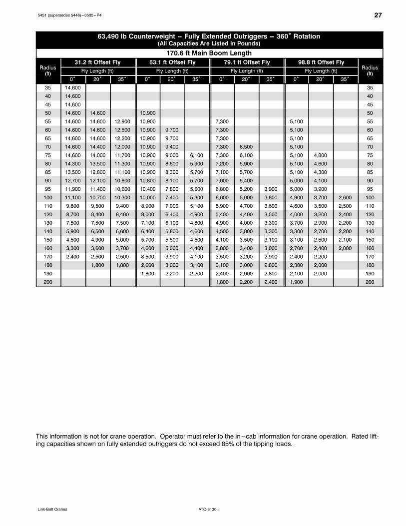
63,490 lb Counterweight -- Fully Extended Outriggers -- 360˚ Rotation(All Capacities Are Listed In Pounds)
170.6 ft Main Boom Length
R di31.2 ft Offset Fly 53.1 ft Offset Fly 79.1 ft Offset Fly 98.8 ft Offset Fly
R diRadius(ft) Fly Length (ft) Fly Length (ft) Fly Length (ft) Fly Length (ft) Radius
(ft)(ft)0˚ 20˚ 35˚ 0˚ 20˚ 35˚ 0˚ 20˚ 35˚ 0˚ 20˚ 35˚
(ft)
35 14,600 35
40 14,600 40
45 14,600 45
50 14,600 14,600 10,900 50
55 14,600 14,600 12,900 10,900 7,300 5,100 55
60 14,600 14,600 12,500 10,900 9,700 7,300 5,100 60
65 14,600 14,600 12,200 10,900 9,700 7,300 5,100 65
70 14,600 14,400 12,000 10,900 9,400 7,300 6,500 5,100 70
75 14,600 14,000 11,700 10,900 9,000 6,100 7,300 6,100 5,100 4,800 75
80 14,300 13,500 11,300 10,900 8,600 5,900 7,200 5,900 5,100 4,600 80
85 13,500 12,800 11,100 10,900 8,300 5,700 7,100 5,700 5,100 4,300 85
90 12,700 12,100 10,800 10,800 8,100 5,700 7,000 5,400 5,000 4,100 90
95 11,900 11,400 10,600 10,400 7,800 5,500 6,800 5,200 3,900 5,000 3,900 95
100 11,100 10,700 10,300 10,000 7,400 5,300 6,600 5,000 3,800 4,900 3,700 2,600 100
110 9,800 9,500 9,400 8,900 7,000 5,100 5,900 4,700 3,600 4,600 3,500 2,500 110
120 8,700 8,400 8,400 8,000 6,400 4,900 5,400 4,400 3,500 4,000 3,200 2,400 120
130 7,500 7,500 7,500 7,100 6,100 4,800 4,900 4,000 3,300 3,700 2,900 2,200 130
140 5,900 6,500 6,600 6,400 5,800 4,600 4,500 3,800 3,300 3,300 2,700 2,200 140
150 4,500 4,900 5,000 5,700 5,500 4,500 4,100 3,500 3,100 3,100 2,500 2,100 150
160 3,300 3,600 3,700 4,600 5,000 4,400 3,800 3,400 3,000 2,700 2,400 2,000 160
170 2,400 2,500 2,500 3,500 3,900 4,100 3,500 3,200 2,900 2,400 2,200 170
180 1,800 1,800 2,600 3,000 3,100 3,100 3,000 2,800 2,300 2,000 180
190 1,800 2,200 2,200 2,400 2,900 2,800 2,100 2,000 190
200 1,800 2,200 2,400 1,900 200
This information is not for crane operation. Operator must refer to the in---cab information for crane operation. Rated lift-ing capacities shown on fully extended outriggers do not exceed 85% of the tipping loads.
28 5451 (supersedes 5446)---0505---P4
ATC-3130 II Link-Belt Cranes
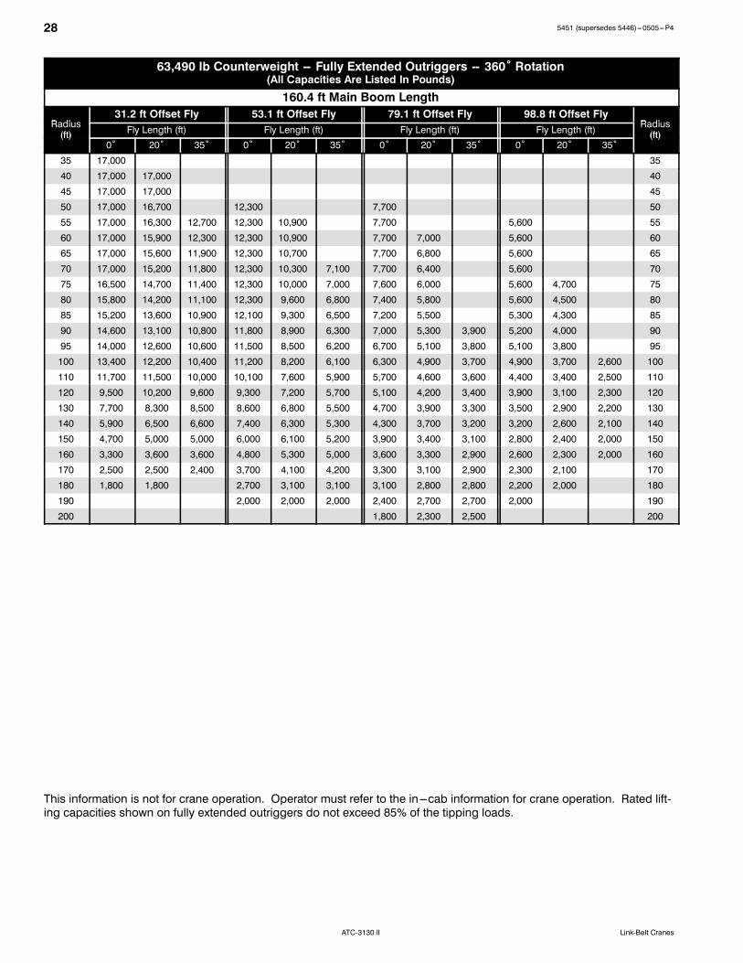
63,490 lb Counterweight -- Fully Extended Outriggers -- 360˚ Rotation(All Capacities Are Listed In Pounds)
160.4 ft Main Boom Length
R di31.2 ft Offset Fly 53.1 ft Offset Fly 79.1 ft Offset Fly 98.8 ft Offset Fly
R diRadius(ft) Fly Length (ft) Fly Length (ft) Fly Length (ft) Fly Length (ft) Radius
(ft)(ft)0˚ 20˚ 35˚ 0˚ 20˚ 35˚ 0˚ 20˚ 35˚ 0˚ 20˚ 35˚
(ft)
35 17,000 35
40 17,000 17,000 40
45 17,000 17,000 45
50 17,000 16,700 12,300 7,700 50
55 17,000 16,300 12,700 12,300 10,900 7,700 5,600 55
60 17,000 15,900 12,300 12,300 10,900 7,700 7,000 5,600 60
65 17,000 15,600 11,900 12,300 10,700 7,700 6,800 5,600 65
70 17,000 15,200 11,800 12,300 10,300 7,100 7,700 6,400 5,600 70
75 16,500 14,700 11,400 12,300 10,000 7,000 7,600 6,000 5,600 4,700 75
80 15,800 14,200 11,100 12,300 9,600 6,800 7,400 5,800 5,600 4,500 80
85 15,200 13,600 10,900 12,100 9,300 6,500 7,200 5,500 5,300 4,300 85
90 14,600 13,100 10,800 11,800 8,900 6,300 7,000 5,300 3,900 5,200 4,000 90
95 14,000 12,600 10,600 11,500 8,500 6,200 6,700 5,100 3,800 5,100 3,800 95
100 13,400 12,200 10,400 11,200 8,200 6,100 6,300 4,900 3,700 4,900 3,700 2,600 100
110 11,700 11,500 10,000 10,100 7,600 5,900 5,700 4,600 3,600 4,400 3,400 2,500 110
120 9,500 10,200 9,600 9,300 7,200 5,700 5,100 4,200 3,400 3,900 3,100 2,300 120
130 7,700 8,300 8,500 8,600 6,800 5,500 4,700 3,900 3,300 3,500 2,900 2,200 130
140 5,900 6,500 6,600 7,400 6,300 5,300 4,300 3,700 3,200 3,200 2,600 2,100 140
150 4,700 5,000 5,000 6,000 6,100 5,200 3,900 3,400 3,100 2,800 2,400 2,000 150
160 3,300 3,600 3,600 4,800 5,300 5,000 3,600 3,300 2,900 2,600 2,300 2,000 160
170 2,500 2,500 2,400 3,700 4,100 4,200 3,300 3,100 2,900 2,300 2,100 170
180 1,800 1,800 2,700 3,100 3,100 3,100 2,800 2,800 2,200 2,000 180
190 2,000 2,000 2,000 2,400 2,700 2,700 2,000 190
200 1,800 2,300 2,500 200
This information is not for crane operation. Operator must refer to the in---cab information for crane operation. Rated lift-ing capacities shown on fully extended outriggers do not exceed 85% of the tipping loads.
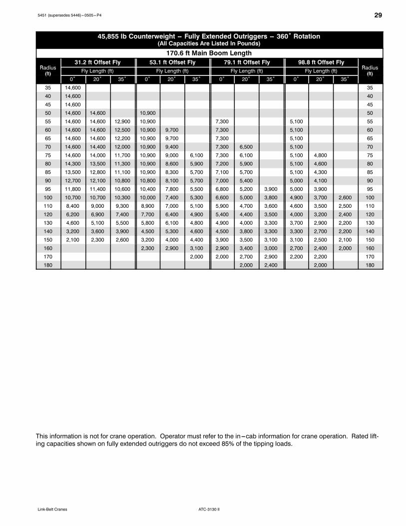
295451 (supersedes 5446)---0505---P4
ATC-3130 IILink-Belt Cranes
45,855 lb Counterweight -- Fully Extended Outriggers -- 360˚ Rotation(All Capacities Are Listed In Pounds)
170.6 ft Main Boom Length
R di31.2 ft Offset Fly 53.1 ft Offset Fly 79.1 ft Offset Fly 98.8 ft Offset Fly
R diRadius(ft) Fly Length (ft) Fly Length (ft) Fly Length (ft) Fly Length (ft) Radius
(ft)(ft)0˚ 20˚ 35˚ 0˚ 20˚ 35˚ 0˚ 20˚ 35˚ 0˚ 20˚ 35˚
(ft)
35 14,600 35
40 14,600 40
45 14,600 45
50 14,600 14,600 10,900 50
55 14,600 14,600 12,900 10,900 7,300 5,100 55
60 14,600 14,600 12,500 10,900 9,700 7,300 5,100 60
65 14,600 14,600 12,200 10,900 9,700 7,300 5,100 65
70 14,600 14,400 12,000 10,900 9,400 7,300 6,500 5,100 70
75 14,600 14,000 11,700 10,900 9,000 6,100 7,300 6,100 5,100 4,800 75
80 14,300 13,500 11,300 10,900 8,600 5,900 7,200 5,900 5,100 4,600 80
85 13,500 12,800 11,100 10,900 8,300 5,700 7,100 5,700 5,100 4,300 85
90 12,700 12,100 10,800 10,800 8,100 5,700 7,000 5,400 5,000 4,100 90
95 11,800 11,400 10,600 10,400 7,800 5,500 6,800 5,200 3,900 5,000 3,900 95
100 10,700 10,700 10,300 10,000 7,400 5,300 6,600 5,000 3,800 4,900 3,700 2,600 100
110 8,400 9,000 9,300 8,900 7,000 5,100 5,900 4,700 3,600 4,600 3,500 2,500 110
120 6,200 6,900 7,400 7,700 6,400 4,900 5,400 4,400 3,500 4,000 3,200 2,400 120
130 4,600 5,100 5,500 5,800 6,100 4,800 4,900 4,000 3,300 3,700 2,900 2,200 130
140 3,200 3,600 3,900 4,500 5,300 4,600 4,500 3,800 3,300 3,300 2,700 2,200 140
150 2,100 2,300 2,600 3,200 4,000 4,400 3,900 3,500 3,100 3,100 2,500 2,100 150
160 2,300 2,900 3,100 2,900 3,400 3,000 2,700 2,400 2,000 160
170 2,000 2,000 2,700 2,900 2,200 2,200 170
180 2,000 2,400 2,000 180
This information is not for crane operation. Operator must refer to the in---cab information for crane operation. Rated lift-ing capacities shown on fully extended outriggers do not exceed 85% of the tipping loads.

30 5451 (supersedes 5446)---0505---P4
ATC-3130 II Link-Belt Cranes
45,855 lb Counterweight -- Fully Extended Outriggers -- 360˚ Rotation(All Capacities Are Listed In Pounds)
160.4 ft Main Boom Length
R di31.2 ft Offset Fly 53.1 ft Offset Fly 79.1 ft Offset Fly 98.8 ft Offset Fly
R diRadius(ft) Fly Length (ft) Fly Length (ft) Fly Length (ft) Fly Length (ft) Radius
(ft)(ft)0˚ 20˚ 35˚ 0˚ 20˚ 35˚ 0˚ 20˚ 35˚ 0˚ 20˚ 35˚
(ft)
35 17,000 35
40 17,000 17,000 40
45 17,000 17,000 45
50 17,000 16,700 12,300 7,700 50
55 17,000 16,300 12,700 12,300 10,900 7,700 5,600 55
60 17,000 15,900 12,300 12,300 10,900 7,700 7,000 5,600 60
65 17,000 15,600 11,900 12,300 10,700 7,700 6,800 5,600 65
70 17,000 15,200 11,800 12,300 10,300 7,100 7,700 6,400 5,600 70
75 16,500 14,700 11,400 12,300 10,000 7,000 7,600 6,000 5,600 4,700 75
80 15,800 14,200 11,100 12,300 9,600 6,800 7,400 5,800 5,600 4,500 80
85 15,200 13,600 10,900 12,100 9,300 6,500 7,200 5,500 5,300 4,300 85
90 13,900 13,100 10,800 11,800 8,900 6,300 7,000 5,300 3,900 5,200 4,000 90
95 12,300 12,500 10,600 11,500 8,500 6,200 6,700 5,100 3,800 5,100 3,800 95
100 10,700 11,600 10,400 11,200 8,200 6,100 6,300 4,900 3,700 4,900 3,700 2,600 100
110 8,400 9,000 9,500 9,800 7,600 5,900 5,700 4,600 3,600 4,400 3,400 2,500 110
120 6,500 6,900 7,400 7,700 7,200 5,700 5,100 4,200 3,400 3,900 3,100 2,300 120
130 4,800 5,300 5,500 6,000 6,800 5,500 4,700 3,900 3,300 3,500 2,900 2,200 130
140 3,300 3,600 3,900 4,600 5,400 5,300 4,300 3,700 3,200 3,200 2,600 2,100 140
150 2,100 2,300 2,600 3,500 4,000 4,400 3,900 3,400 3,100 2,800 2,400 2,000 150
160 2,400 2,900 3,100 3,100 3,300 2,900 2,600 2,300 2,000 160
170 2,000 2,000 2,200 2,900 2,900 2,300 2,100 170
180 1,900 2,400 1,800 2,000 180
This information is not for crane operation. Operator must refer to the in---cab information for crane operation. Rated lift-ing capacities shown on fully extended outriggers do not exceed 85% of the tipping loads.

315451 (supersedes 5446)---0505---P4
ATC-3130 IILink-Belt Cranes
24,250 lb Counterweight -- Fully Extended Outriggers -- 360˚ Rotation(All Capacities Are Listed In Pounds)
170.6 ft Main Boom Length
R di31.2 ft Offset Fly 53.1 ft Offset Fly 79.1 ft Offset Fly 98.8 ft Offset Fly
R diRadius(ft) Fly Length (ft) Fly Length (ft) Fly Length (ft) Fly Length (ft) Radius
(ft)(ft)0˚ 20˚ 35˚ 0˚ 20˚ 35˚ 0˚ 20˚ 35˚ 0˚ 20˚ 35˚
(ft)
35 14,600 35
40 14,600 40
45 14,600 45
50 14,600 14,600 10,900 50
55 14,600 14,600 12,900 10,900 7,300 5,100 55
60 14,600 14,600 12,500 10,900 9,700 7,300 5,100 60
65 14,600 14,600 12,200 10,900 9,700 7,300 5,100 65
70 14,600 14,400 12,000 10,900 9,400 7,300 6,500 5,100 70
75 13,400 14,000 11,700 10,900 9,000 6,100 7,300 6,100 5,100 4,800 75
80 11,500 12,900 11,300 10,900 8,600 5,900 7,200 5,900 5,100 4,600 80
85 9,800 11,000 11,100 10,900 8,300 5,700 7,100 5,700 5,100 4,300 85
90 8,300 9,500 10,100 9,700 8,100 5,700 7,000 5,400 5,000 4,100 90
95 7,000 8,000 8,800 8,400 7,800 5,500 6,800 5,200 3,900 5,000 3,900 95
100 5,900 6,700 7,400 7,200 7,400 5,300 6,600 5,000 3,800 4,900 3,700 2,600 100
110 3,900 4,700 5,200 5,100 6,500 5,100 5,800 4,700 3,600 4,600 3,500 2,500 110
120 2,400 2,900 3,400 3,600 4,800 4,900 4,300 4,400 3,500 4,000 3,200 2,400 120
130 1,800 2,300 3,400 4,000 3,000 4,000 3,300 3,300 2,900 2,200 130
140 1,900 3,200 3,300 2,200 2,700 2,200 140
150 2,100 2,700 2,500 2,100 150
160 2,000 160
This information is not for crane operation. Operator must refer to the in---cab information for crane operation. Rated lift-ing capacities shown on fully extended outriggers do not exceed 85% of the tipping loads.

32 5451 (supersedes 5446)---0505---P4
ATC-3130 II Link-Belt Cranes
24,250 lb Counterweight -- Fully Extended Outriggers -- 360˚ Rotation(All Capacities Are Listed In Pounds)
160.4 ft Main Boom Length
R di31.2 ft Offset Fly 53.1 ft Offset Fly 79.1 ft Offset Fly 98.8 ft Offset Fly
R diRadius(ft) Fly Length (ft) Fly Length (ft) Fly Length (ft) Fly Length (ft) Radius
(ft)(ft)0˚ 20˚ 35˚ 0˚ 20˚ 35˚ 0˚ 20˚ 35˚ 0˚ 20˚ 35˚
(ft)
35 17,000 35
40 17,000 17,000 40
45 17,000 17,000 45
50 17,000 16,700 12,300 7,700 50
55 17,000 16,300 12,700 12,300 10,900 7,700 5,600 55
60 17,000 15,900 12,300 12,300 10,900 7,700 7,000 5,600 60
65 17,000 15,600 11,900 12,300 10,700 7,700 6,800 5,600 65
70 15,500 15,200 11,800 12,300 10,300 7,100 7,700 6,400 5,600 70
75 13,600 14,300 11,400 12,300 10,000 7,000 7,600 6,000 5,600 4,700 75
80 11,700 12,900 11,100 12,100 9,600 6,800 7,400 5,800 5,600 4,500 80
85 9,800 11,000 10,900 11,200 9,300 6,500 7,200 5,500 5,300 4,300 85
90 8,500 9,500 10,000 9,800 8,900 6,300 7,000 5,300 3,900 5,200 4,000 90
95 7,200 8,100 8,800 8,500 8,500 6,200 6,700 5,100 3,800 5,100 3,800 95
100 5,900 6,900 7,400 7,400 8,100 6,100 6,300 4,900 3,700 4,900 3,700 2,600 100
110 3,900 4,700 5,200 5,400 6,600 5,900 5,700 4,600 3,600 4,400 3,400 2,500 110
120 2,400 3,100 3,400 3,800 4,800 5,500 4,600 4,200 3,400 3,900 3,100 2,300 120
130 2,000 2,400 3,400 4,000 3,100 3,900 3,300 3,500 2,900 2,200 130
140 2,200 2,600 2,000 3,200 3,200 2,400 2,600 2,100 140
150 2,100 2,900 2,400 2,000 150
160 2,000 2,000 160
This information is not for crane operation. Operator must refer to the in---cab information for crane operation. Rated lift-ing capacities shown on fully extended outriggers do not exceed 85% of the tipping loads.
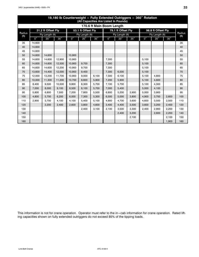
335451 (supersedes 5446)---0505---P4
ATC-3130 IILink-Belt Cranes
19,180 lb Counterweight -- Fully Extended Outriggers -- 360˚ Rotation(All Capacities Are Listed In Pounds)
170.6 ft Main Boom Length
R di31.2 ft Offset Fly 53.1 ft Offset Fly 79.1 ft Offset Fly 98.8 ft Offset Fly
R diRadius(ft) Fly Length (ft) Fly Length (ft) Fly Length (ft) Fly Length (ft) Radius
(ft)(ft)0˚ 20˚ 35˚ 0˚ 20˚ 35˚ 0˚ 20˚ 35˚ 0˚ 20˚ 35˚
(ft)
35 14,600 35
40 14,600 40
45 14,600 45
50 14,600 14,600 10,900 50
55 14,600 14,600 12,900 10,900 7,300 5,100 55
60 14,600 14,600 12,500 10,900 9,700 7,300 5,100 60
65 14,600 14,600 12,200 10,900 9,700 7,300 5,100 65
70 13,600 14,400 12,000 10,900 9,400 7,300 6,500 5,100 70
75 12,000 13,200 11,700 10,900 9,000 6,100 7,300 6,100 5,100 4,800 75
80 10,000 11,300 11,200 10,700 8,600 5,900 7,200 5,900 5,100 4,600 80
85 8,400 9,500 10,500 9,800 8,300 5,700 7,100 5,700 5,100 4,300 85
90 7,000 8,000 9,100 8,500 8,100 5,700 7,000 5,400 5,000 4,100 90
95 5,800 6,800 7,500 7,200 7,800 5,500 6,800 5,200 3,900 5,000 3,900 95
100 4,800 5,700 6,200 6,000 7,300 5,300 6,500 5,000 3,800 4,900 3,700 2,600 100
110 2,900 3,700 4,100 4,100 5,400 5,100 4,900 4,700 3,600 4,600 3,500 2,500 110
120 2,200 2,400 2,600 3,800 4,600 3,400 4,400 3,500 3,600 3,200 2,400 120
130 2,400 3,100 2,100 3,500 3,300 2,400 2,900 2,200 130
140 2,400 3,200 2,600 2,200 140
150 2,100 2,100 150
160 1,900 160
This information is not for crane operation. Operator must refer to the in---cab information for crane operation. Rated lift-ing capacities shown on fully extended outriggers do not exceed 85% of the tipping loads.
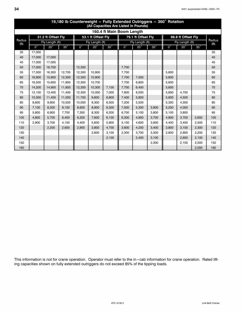
34 5451 (supersedes 5446)---0505---P4
ATC-3130 II Link-Belt Cranes
19,180 lb Counterweight -- Fully Extended Outriggers -- 360˚ Rotation(All Capacities Are Listed In Pounds)
160.4 ft Main Boom Length
R di31.2 ft Offset Fly 53.1 ft Offset Fly 79.1 ft Offset Fly 98.8 ft Offset Fly
R diRadius(ft) Fly Length (ft) Fly Length (ft) Fly Length (ft) Fly Length (ft) Radius
(ft)(ft)0˚ 20˚ 35˚ 0˚ 20˚ 35˚ 0˚ 20˚ 35˚ 0˚ 20˚ 35˚
(ft)
35 17,000 35
40 17,000 17,000 40
45 17,000 17,000 45
50 17,000 16,700 12,300 7,700 50
55 17,000 16,300 12,700 12,300 10,900 7,700 5,600 55
60 16,900 15,900 12,300 12,300 10,900 7,700 7,000 5,600 60
65 16,500 15,600 11,900 12,300 10,700 7,700 6,800 5,600 65
70 14,200 14,900 11,800 12,300 10,300 7,100 7,700 6,400 5,600 70
75 12,100 13,400 11,400 12,300 10,000 7,000 7,600 6,000 5,600 4,700 75
80 10,300 11,400 11,000 11,700 9,600 6,800 7,400 5,800 5,600 4,500 80
85 8,600 9,600 10,500 10,000 9,300 6,500 7,200 5,500 5,300 4,300 85
90 7,100 8,200 9,100 8,600 8,900 6,300 7,000 5,300 3,900 5,200 4,000 90
95 5,800 6,900 7,700 7,300 8,300 6,200 6,700 5,100 3,800 5,100 3,800 95
100 4,800 5,700 6,400 6,200 7,600 6,100 6,300 4,900 3,700 4,900 3,700 2,600 100
110 2,900 3,700 4,100 4,400 5,600 5,900 5,100 4,600 3,600 4,400 3,400 2,500 110
120 2,200 2,600 2,900 3,800 4,700 3,600 4,200 3,400 3,800 3,100 2,300 120
130 2,600 3,100 2,300 3,700 3,300 2,600 2,900 2,200 130
140 2,100 2,400 3,100 2,600 2,100 140
150 2,300 2,100 2,000 150
160 2,000 160
This information is not for crane operation. Operator must refer to the in---cab information for crane operation. Rated lift-ing capacities shown on fully extended outriggers do not exceed 85% of the tipping loads.
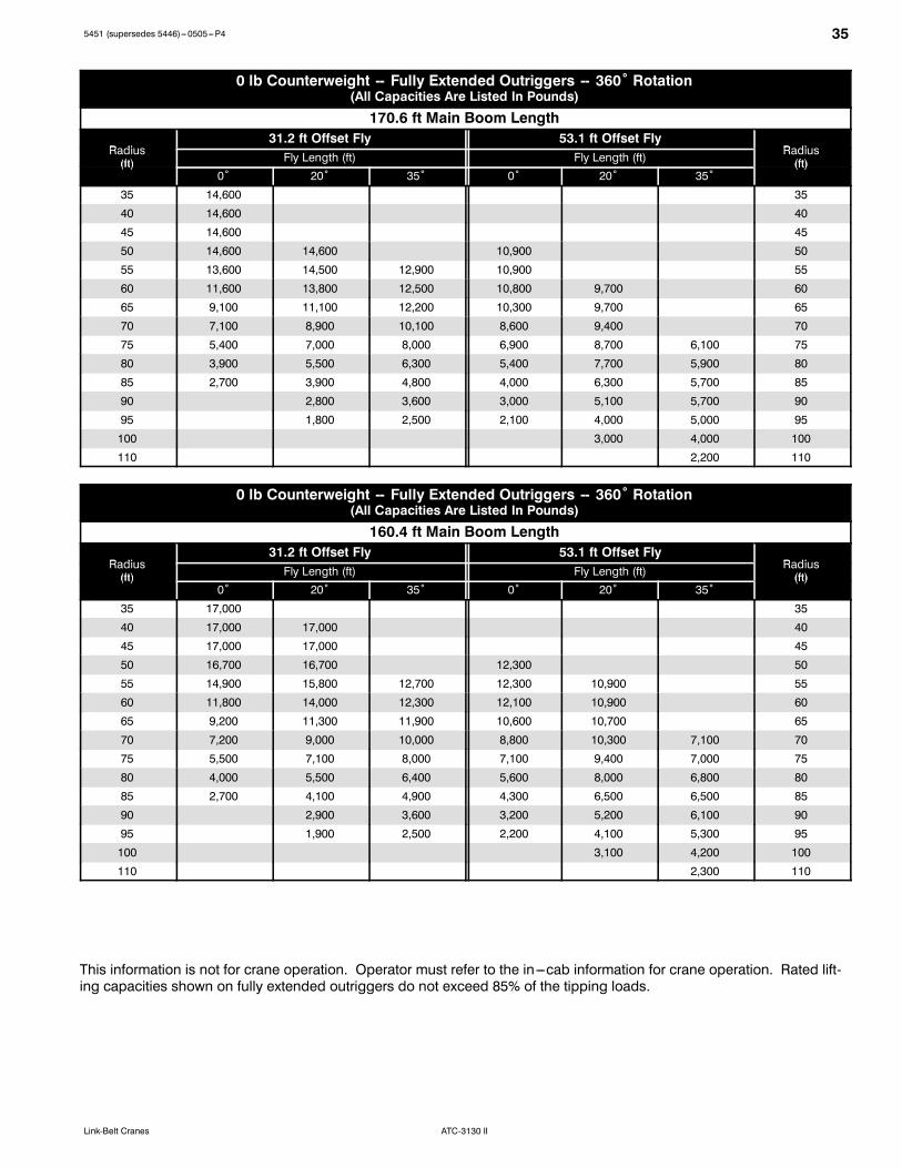
355451 (supersedes 5446)---0505---P4
ATC-3130 IILink-Belt Cranes
0 lb Counterweight -- Fully Extended Outriggers -- 360˚ Rotation(All Capacities Are Listed In Pounds)
170.6 ft Main Boom Length
R di31.2 ft Offset Fly 53.1 ft Offset Fly
R diRadius(ft) Fly Length (ft) Fly Length (ft) Radius
(ft)(ft)0˚ 20˚ 35˚ 0˚ 20˚ 35˚
(ft)
35 14,600 35
40 14,600 40
45 14,600 45
50 14,600 14,600 10,900 50
55 13,600 14,500 12,900 10,900 55
60 11,600 13,800 12,500 10,800 9,700 60
65 9,100 11,100 12,200 10,300 9,700 65
70 7,100 8,900 10,100 8,600 9,400 70
75 5,400 7,000 8,000 6,900 8,700 6,100 75
80 3,900 5,500 6,300 5,400 7,700 5,900 80
85 2,700 3,900 4,800 4,000 6,300 5,700 85
90 2,800 3,600 3,000 5,100 5,700 90
95 1,800 2,500 2,100 4,000 5,000 95
100 3,000 4,000 100
110 2,200 110
0 lb Counterweight -- Fully Extended Outriggers -- 360˚ Rotation(All Capacities Are Listed In Pounds)
160.4 ft Main Boom Length
R di31.2 ft Offset Fly 53.1 ft Offset Fly
R diRadius(ft) Fly Length (ft) Fly Length (ft) Radius
(ft)(ft)0˚ 20˚ 35˚ 0˚ 20˚ 35˚
(ft)
35 17,000 35
40 17,000 17,000 40
45 17,000 17,000 45
50 16,700 16,700 12,300 50
55 14,900 15,800 12,700 12,300 10,900 55
60 11,800 14,000 12,300 12,100 10,900 60
65 9,200 11,300 11,900 10,600 10,700 65
70 7,200 9,000 10,000 8,800 10,300 7,100 70
75 5,500 7,100 8,000 7,100 9,400 7,000 75
80 4,000 5,500 6,400 5,600 8,000 6,800 80
85 2,700 4,100 4,900 4,300 6,500 6,500 85
90 2,900 3,600 3,200 5,200 6,100 90
95 1,900 2,500 2,200 4,100 5,300 95
100 3,100 4,200 100
110 2,300 110
This information is not for crane operation. Operator must refer to the in---cab information for crane operation. Rated lift-ing capacities shown on fully extended outriggers do not exceed 85% of the tipping loads.

5451 (supersedes 5446)---0505---P4
ATC-3130 II Link-Belt Cranes
Link-Belt Construction Equipment Company Lexington, Kentucky www.linkbelt.comRLink-Belt is a registered trademark. Copyright 2005. We are constantly improving our products and therefore reserve the right to change designs and specifications.