Embed Size (px)
Citation preview
1
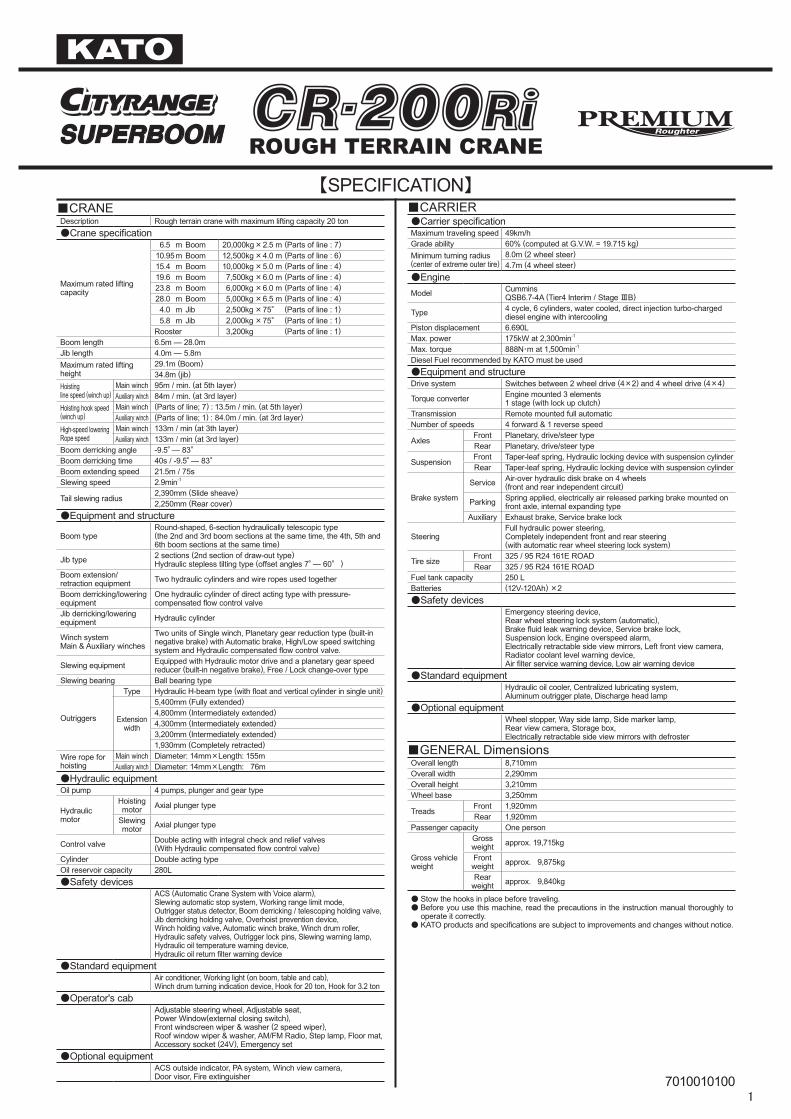
【SPECIFICATION】■CRANEDescription Rough terrain crane with maximum lifting capacity 20 ton●Crane specification
Maximum rated lifting capacity
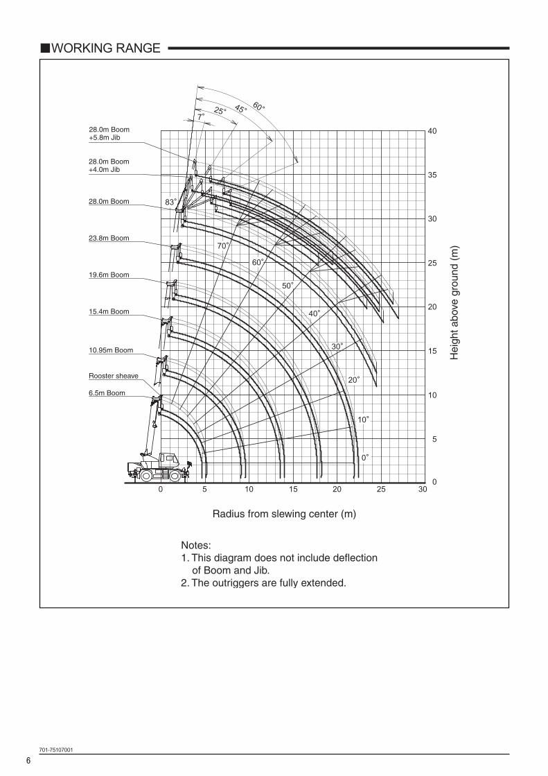
6.5 m Boom 20,000kg × 2.5 m (Parts of line : 7) 10.95 m Boom 12,500kg × 4.0 m (Parts of line : 6) 15.4 m Boom 10,000kg × 5.0 m (Parts of line : 4) 19.6 m Boom 7,500kg × 6.0 m (Parts of line : 4) 23.8 m Boom 6,000kg × 6.0 m (Parts of line : 4) 28.0 m Boom 5,000kg × 6.5 m (Parts of line : 4) 4.0 m Jib 2,500kg × 75° (Parts of line : 1) 5.8 m Jib 2,000kg × 75° (Parts of line : 1)Rooster 3,200kg (Parts of line : 1)
Boom length 6.5m ― 28.0mJib length 4.0m ― 5.8mMaximum rated lifting height
29.1m (Boom)34.8m (jib)
Hoisting line speed (winch up)
Main winch 95m / min. (at 5th layer)Auxiliary winch 84m / min. (at 3rd layer)
Hoisting hook speed(winch up)
Main winch (Parts of line; 7) : 13.5m / min. (at 5th layer)Auxiliary winch (Parts of line; 1) : 84.0m / min. (at 3rd layer)
High-speed loweringRope speed
Main winch 133m / min (at 3th layer)Auxiliary winch 133m / min (at 3rd layer)
Boom derricking angle -9.5° ― 83°Boom derricking time 40s / -9.5° ― 83°Boom extending speed 21.5m / 75sSlewing speed 2.9min-1
Tail slewing radius2,390mm (Slide sheave)2,250mm (Rear cover)
●Equipment and structure
Boom typeRound-shaped, 6-section hydraulically telescopic type(the 2nd and 3rd boom sections at the same time, the 4th, 5th and 6th boom sections at the same time)
Jib type 2 sections (2nd section of draw-out type)Hydraulic stepless tilting type (offset angles 7° ― 60°)
Boom extension/retraction equipment Two hydraulic cylinders and wire ropes used together
Boom derricking/lowering equipment
One hydraulic cylinder of direct acting type with pressure-compensated flow control valve
Jib derricking/lowering equipment Hydraulic cylinder
Winch system Main & Auxiliary winches
Two units of Single winch, Planetary gear reduction type (built-in negative brake) with Automatic brake, High/Low speed switching system and Hydraulic compensated flow control valve.
Slewing equipment Equipped with Hydraulic motor drive and a planetary gear speed reducer (built-in negative brake), Free / Lock change-over type
Slewing bearing Ball bearing type
Outriggers
Type Hydraulic H-beam type (with float and vertical cylinder in single unit)
Extension width
5,400mm (Fully extended)4,800mm (Intermediately extended)4,300mm (Intermediately extended)3,200mm (Intermediately extended)1,930mm (Completely retracted)
Wire rope for hoisting
Main winch Diameter: 14mm×Length: 155mAuxiliary winch Diameter: 14mm×Length: 76m
●Hydraulic equipmentOil pump 4 pumps, plunger and gear type
Hydraulic motor
Hoisting motor Axial plunger type
Slewing motor Axial plunger type
Control valve Double acting with integral check and relief valves(With Hydraulic compensated flow control valve)
Cylinder Double acting typeOil reservoir capacity 280L●Safety devices
ACS (Automatic Crane System with Voice alarm), Slewing automatic stop system, Working range limit mode, Outrigger status detector, Boom derricking / telescoping holding valve, Jib derricking holding valve, Overhoist prevention device, Winch holding valve, Automatic winch brake, Winch drum roller, Hydraulic safety valves, Outrigger lock pins, Slewing warning lamp, Hydraulic oil temperature warning device, Hydraulic oil return filter warning device
●Standard equipmentAir conditioner, Working light (on boom, table and cab), Winch drum turning indication device, Hook for 20 ton, Hook for 3.2 ton
●Operator's cabAdjustable steering wheel, Adjustable seat, Power Window(external closing switch), Front windscreen wiper & washer (2 speed wiper), Roof window wiper & washer, AM/FM Radio, Step lamp, Floor mat, Accessory socket (24V), Emergency set
●Optional equipmentACS outside indicator, PA system, Winch view camera, Door visor, Fire extinguisher
■CARRIER●Carrier specificationMaximum traveling speed 49km/hGrade ability 60% (computed at G.V.W. = 19.715 kg)Minimum turning radius(center of extreme outer tire)
8.0m (2 wheel steer) 4.7m (4 wheel steer)
●EngineModel Cummins
QSB6.7-4A (Tier4 Interim / Stage ⅢB)
Type 4 cycle, 6 cylinders, water cooled, direct injection turbo-charged diesel engine with intercooling
Piston displacement 6.690LMax. power 175kW at 2,300min-1
Max. torque 888N・m at 1,500min-1
Diesel Fuel recommended by KATO must be used●Equipment and structureDrive system Switches between 2 wheel drive (4×2) and 4 wheel drive (4×4)
Torque converter Engine mounted 3 elements1 stage (with lock up clutch)
Transmission Remote mounted full automaticNumber of speeds 4 forward & 1 reverse speed
AxlesFront Planetary, drive/steer typeRear Planetary, drive/steer type
SuspensionFront Taper-leaf spring, Hydraulic locking device with suspension cylinderRear Taper-leaf spring, Hydraulic locking device with suspension cylinder
Brake system
Service Air-over hydraulic disk brake on 4 wheels(front and rear independent circuit)
Parking Spring applied, electrically air released parking brake mounted on front axle, internal expanding type
Auxiliary Exhaust brake, Service brake lock
SteeringFull hydraulic power steering, Completely independent front and rear steering(with automatic rear wheel steering lock system)
Tire sizeFront 325 / 95 R24 161E ROADRear 325 / 95 R24 161E ROAD
Fuel tank capacity 250 LBatteries (12V-120Ah) ×2●Safety devices
Emergency steering device, Rear wheel steering lock system (automatic), Brake fluid leak warning device, Service brake lock, Suspension lock, Engine overspeed alarm, Electrically retractable side view mirrors, Left front view camera, Radiator coolant level warning device, Air filter service warning device, Low air warning device
●Standard equipmentHydraulic oil cooler, Centralized lubricating system, Aluminum outrigger plate, Discharge head lamp
●Optional equipmentWheel stopper, Way side lamp, Side marker lamp, Rear view camera, Storage box, Electrically retractable side view mirrors with defroster
■GENERAL DimensionsOverall length 8,710mmOverall width 2,290mmOverall height 3,210mmWheel base 3,250mm
TreadsFront 1,920mmRear 1,920mm
Passenger capacity One person
Gross vehicle weight
Gross weight approx. 19,715kg
Front weight approx. 9,875kg
Rear weight approx. 9,840kg
● Stow the hooks in place before traveling.● Before you use this machine, read the precautions in the instruction manual thoroughly to
operate it correctly.● KATO products and specifications are subject to improvements and changes without notice.
7010010100
ROUGH TERRAIN CRANE
2
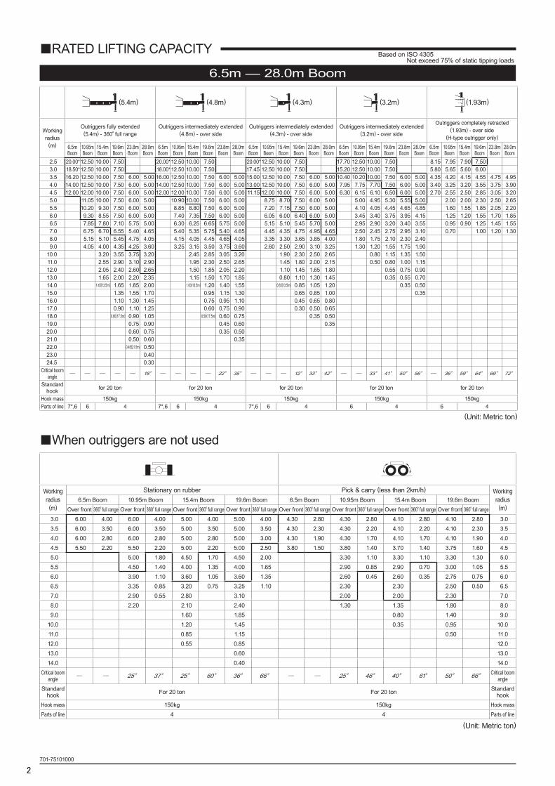
(5.4m) (4.8m) (4.3m) (3.2m) (1.93m)
Working radius
(m)
Outriggers fully extended(5.4m) - 360°full range
Outriggers intermediately extended(4.8m) - over side
Outriggers intermediately extended(4.3m) - over side
Outriggers intermediately extended(3.2m) - over side
Outriggers completely retracted(1.93m) - over side
(H-type outrigger only)
6.5mBoom
10.95mBoom
15.4mBoom
19.6mBoom
23.8mBoom
28.0mBoom
6.5mBoom
10.95mBoom
15.4mBoom
19.6mBoom
23.8mBoom
28.0mBoom
6.5mBoom
10.95mBoom
15.4mBoom
19.6mBoom
23.8mBoom
28.0mBoom
6.5mBoom
10.95mBoom
15.4mBoom
19.6mBoom
23.8mBoom
28.0mBoom
6.5mBoom
10.95mBoom
15.4mBoom
19.6mBoom
23.8mBoom
28.0mBoom
2.5 20.00*12.50 10.00 7.50 20.00*12.50 10.00 7.50 20.00*12.50 10.00 7.50 17.70 12.50 10.00 7.50 8.15 7.95 7.90 7.503.0 18.50*12.50 10.00 7.50 18.00*12.50 10.00 7.50 17.45 12.50 10.00 7.50 15.20 12.50 10.00 7.50 5.80 5.65 5.60 6.003.5 16.20 12.50 10.00 7.50 6.00 5.00 16.00 12.50 10.00 7.50 6.00 5.00 15.00 12.50 10.00 7.50 6.00 5.00 10.40 10.20 10.00 7.50 6.00 5.00 4.35 4.20 4.15 4.55 4.75 4.954.0 14.00 12.50 10.00 7.50 6.00 5.00 14.00 12.50 10.00 7.50 6.00 5.00 13.00 12.50 10.00 7.50 6.00 5.00 7.95 7.75 7.70 7.50 6.00 5.00 3.40 3.25 3.20 3.55 3.75 3.904.5 12.00 12.00 10.00 7.50 6.00 5.00 12.00 12.00 10.00 7.50 6.00 5.00 11.15 12.00 10.00 7.50 6.00 5.00 6.30 6.15 6.10 6.50 6.00 5.00 2.70 2.55 2.50 2.85 3.05 3.205.0 11.05 10.00 7.50 6.00 5.00 10.90 10.00 7.50 6.00 5.00 8.75 8.70 7.50 6.00 5.00 5.00 4.95 5.30 5.55 5.00 2.00 2.00 2.30 2.50 2.655.5 10.20 9.30 7.50 6.00 5.00 8.85 8.80 7.50 6.00 5.00 7.20 7.15 7.50 6.00 5.00 4.10 4.05 4.45 4.65 4.85 1.60 1.55 1.85 2.05 2.206.0 9.30 8.55 7.50 6.00 5.00 7.40 7.35 7.50 6.00 5.00 6.05 6.00 6.40 6.00 5.00 3.45 3.40 3.75 3.95 4.15 1.25 1.20 1.55 1.70 1.856.5 7.85 7.80 7.10 5.75 5.00 6.30 6.25 6.65 5.75 5.00 5.15 5.10 5.45 5.70 5.00 2.95 2.90 3.20 3.40 3.55 0.95 0.90 1.25 1.45 1.557.0 6.75 6.70 6.55 5.40 4.65 5.40 5.35 5.75 5.40 4.65 4.45 4.35 4.75 4.95 4.65 2.50 2.45 2.75 2.95 3.10 0.70 1.00 1.20 1.308.0 5.15 5.10 5.45 4.75 4.05 4.15 4.05 4.45 4.65 4.05 3.35 3.30 3.65 3.85 4.00 1.80 1.75 2.10 2.30 2.409.0 4.05 4.00 4.35 4.25 3.60 3.25 3.15 3.50 3.75 3.60 2.60 2.50 2.90 3.10 3.25 1.30 1.20 1.55 1.75 1.90
10.0 3.20 3.55 3.75 3.20 2.45 2.85 3.05 3.20 1.90 2.30 2.50 2.65 0.80 1.15 1.35 1.5011.0 2.55 2.90 3.10 2.90 1.95 2.30 2.50 2.65 1.45 1.80 2.00 2.15 0.50 0.80 1.00 1.1512.0 2.05 2.40 2.60 2.65 1.50 1.85 2.05 2.20 1.10 1.45 1.65 1.80 0.55 0.75 0.9013.0 1.65 2.00 2.20 2.35 1.15 1.50 1.70 1.85 0.80 1.10 1.30 1.45 0.35 0.55 0.7014.0 1.45(13.5m) 1.65 1.85 2.00 1.00(13.5m) 1.20 1.40 1.55 0.65(13.5m) 0.85 1.05 1.20 0.35 0.5015.0 1.35 1.55 1.70 0.95 1.15 1.30 0.65 0.85 1.00 0.3516.0 1.10 1.30 1.45 0.75 0.95 1.10 0.45 0.65 0.8017.0 0.90 1.10 1.25 0.60 0.75 0.90 0.30 0.50 0.6518.0 0.80(17.5m) 0.90 1.05 0.50(17.5m) 0.60 0.75 0.35 0.5019.0 0.75 0.90 0.45 0.60 0.3520.0 0.60 0.75 0.35 0.5021.0 0.50 0.60 0.3522.0 0.45(21.5m) 0.5023.0 0.4024.5 0.30
Critical boomangle ─ ─ ─ ─ ─ 18° ─ ─ ─ ─ 22° 35° ─ ─ ─ 12° 33° 42° ─ ─ 33° 41° 50° 56° ─ 36° 59° 64° 69° 72°
Standard hook for 20 ton for 20 ton for 20 ton for 20 ton for 20 ton
Hook mass 150kg 150kg 150kg 150kg 150kgParts of line 7*,6 6 4 7*,6 6 4 7*,6 6 4 6 4 6 4
(Unit: Metric ton)
701-75101000
■When outriggers are not used
Workingradius
(m)
Stationary on rubber Pick & carry (less than 2km/h) Workingradius
(m)6.5m Boom 10.95m Boom 15.4m Boom 19.6m Boom 6.5m Boom 10.95m Boom 15.4m Boom 19.6m Boom
Over front 360°full range Over front 360°full range Over front 360°full range Over front 360°full range Over front 360°full range Over front 360°full range Over front 360°full range Over front 360°full range3.0 6.00 4.00 6.00 4.00 5.00 4.00 5.00 4.00 4.30 2.80 4.30 2.80 4.10 2.80 4.10 2.80 3.0 3.5 6.00 3.50 6.00 3.50 5.00 3.50 5.00 3.50 4.30 2.30 4.30 2.20 4.10 2.20 4.10 2.30 3.5 4.0 6.00 2.80 6.00 2.80 5.00 2.80 5.00 3.00 4.30 1.90 4.30 1.70 4.10 1.70 4.10 1.90 4.0 4.5 5.50 2.20 5.50 2.20 5.00 2.20 5.00 2.50 3.80 1.50 3.80 1.40 3.70 1.40 3.75 1.60 4.5 5.0 5.00 1.80 4.50 1.70 4.50 2.00 3.30 1.10 3.30 1.10 3.30 1.30 5.0 5.5 4.50 1.40 4.00 1.35 4.00 1.65 2.90 0.85 2.90 0.70 3.00 1.05 5.5 6.0 3.90 1.10 3.60 1.05 3.60 1.35 2.60 0.45 2.60 0.35 2.75 0.75 6.0 6.5 3.35 0.85 3.20 0.75 3.25 1.10 2.30 2.30 2.50 0.50 6.5 7.0 2.90 0.55 2.80 3.10 2.00 2.00 2.30 7.0 8.0 2.20 2.10 2.40 1.30 1.35 1.80 8.0 9.0 1.60 1.85 0.80 1.40 9.0
10.0 1.20 1.45 0.35 0.95 10.0 11.0 0.85 1.15 0.50 11.0 12.0 0.55 0.85 12.0 13.0 0.60 13.0 14.0 0.40 14.0
Critical boomangle ─ ─ 25° 37° 25° 60° 36° 66° ─ ─ 25° 46° 40° 61° 50° 66° Critical boom
angleStandard
hook For 20 ton For 20 ton Standard hook
Hook mass 150kg 150kg Hook massParts of line 4 4 Parts of line
(Unit: Metric ton)
■RATED LIFTING CAPACITY
6.5m ― 28.0m Boom
Based on ISO 4305 Not exceed 75% of static tipping loads
3
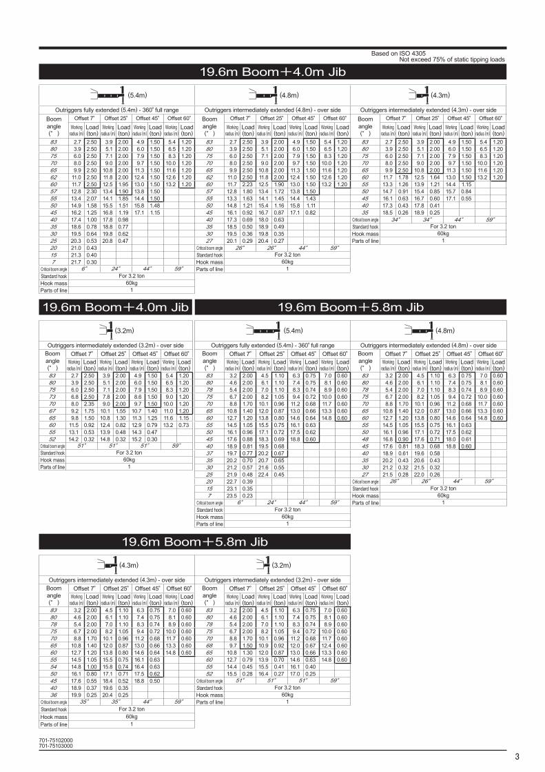
19.6m Boom+4.0m Jib
19.6m Boom+4.0m Jib
19.6m Boom+5.8m Jib
19.6m Boom+5.8m Jib
(5.4m) (4.8m) (4.3m)
Outriggers fully extended (5.4m) - 360°full range Outriggers intermediately extended (4.8m) - over side Outriggers intermediately extended (4.3m) - over sideBoom angle(°)
Offset 7° Offset 25° Offset 45° Offset 60° Boom angle(°)
Offset 7° Offset 25° Offset 45° Offset 60° Boom angle(°)
Offset 7° Offset 25° Offset 45° Offset 60°Working
radius (m)Load(ton)
Workingradius (m)
Load(ton)
Workingradius (m)
Load(ton)
Workingradius (m)
Load(ton)
Workingradius (m)
Load(ton)
Workingradius (m)
Load(ton)
Workingradius (m)
Load(ton)
Workingradius (m)
Load(ton)
Workingradius (m)
Load(ton)
Workingradius (m)
Load(ton)
Workingradius (m)
Load(ton)
Workingradius (m)
Load(ton)
83 2.7 2.50 3.9 2.00 4.9 1.50 5.4 1.20 83 2.7 2.50 3.9 2.00 4.9 1.50 5.4 1.20 83 2.7 2.50 3.9 2.00 4.9 1.50 5.4 1.2080 3.9 2.50 5.1 2.00 6.0 1.50 6.5 1.20 80 3.9 2.50 5.1 2.00 6.0 1.50 6.5 1.20 80 3.9 2.50 5.1 2.00 6.0 1.50 6.5 1.2075 6.0 2.50 7.1 2.00 7.9 1.50 8.3 1.20 75 6.0 2.50 7.1 2.00 7.9 1.50 8.3 1.20 75 6.0 2.50 7.1 2.00 7.9 1.50 8.3 1.2070 8.0 2.50 9.0 2.00 9.7 1.50 10.0 1.20 70 8.0 2.50 9.0 2.00 9.7 1.50 10.0 1.20 70 8.0 2.50 9.0 2.00 9.7 1.50 10.0 1.2065 9.9 2.50 10.8 2.00 11.3 1.50 11.6 1.20 65 9.9 2.50 10.8 2.00 11.3 1.50 11.6 1.20 65 9.9 2.50 10.8 2.00 11.3 1.50 11.6 1.2062 11.0 2.50 11.8 2.00 12.4 1.50 12.6 1.20 62 11.0 2.50 11.8 2.00 12.4 1.50 12.6 1.20 60 11.7 1.78 12.5 1.64 13.0 1.50 13.2 1.2060 11.7 2.50 12.5 1.95 13.0 1.50 13.2 1.20 60 11.7 2.23 12.5 1.90 13.0 1.50 13.2 1.20 55 13.3 1.26 13.9 1.21 14.4 1.1557 12.8 2.30 13.4 1.90 13.8 1.50 57 12.8 1.80 13.4 1.72 13.8 1.50 50 14.7 0.91 15.4 0.85 15.7 0.8455 13.4 2.07 14.1 1.85 14.4 1.50 55 13.3 1.63 14.1 1.45 14.4 1.43 45 16.1 0.63 16.7 0.60 17.1 0.5550 14.9 1.58 15.5 1.51 15.8 1.48 50 14.8 1.21 15.4 1.16 15.8 1.11 40 17.3 0.43 17.8 0.4145 16.2 1.25 16.8 1.19 17.1 1.15 45 16.1 0.92 16.7 0.87 17.1 0.82 35 18.5 0.26 18.9 0.2540 17.4 1.00 17.8 0.98 40 17.3 0.69 18.0 0.63 Critical boom angle 34° 34° 44° 59°35 18.6 0.78 18.8 0.77 35 18.5 0.50 18.9 0.49 Standard hook For 3.2 ton30 19.5 0.64 19.8 0.62 30 19.5 0.36 19.8 0.35 Hook mass 60kg25 20.3 0.53 20.8 0.47 27 20.1 0.29 20.4 0.27 Parts of line 120 21.0 0.43 Critical boom angle 26° 26° 44° 59°15 21.3 0.40 Standard hook For 3.2 ton7 21.7 0.30 Hook mass 60kg
Critical boom angle 6° 24° 44° 59° Parts of line 1Standard hook For 3.2 tonHook mass 60kgParts of line 1
701-75102000701-75103000
(3.2m)
Outriggers intermediately extended (3.2m) - over sideBoom angle(°)
Offset 7° Offset 25° Offset 45° Offset 60°Working
radius (m)Load(ton)
Workingradius (m)
Load(ton)
Workingradius (m)
Load(ton)
Workingradius (m)
Load(ton)
83 2.7 2.50 3.9 2.00 4.9 1.50 5.4 1.2080 3.9 2.50 5.1 2.00 6.0 1.50 6.5 1.2075 6.0 2.50 7.1 2.00 7.9 1.50 8.3 1.2073 6.8 2.50 7.8 2.00 8.6 1.50 9.0 1.2070 8.0 2.35 9.0 2.00 9.7 1.50 10.0 1.2067 9.2 1.75 10.1 1.55 10.7 1.40 11.0 1.2065 9.8 1.50 10.8 1.30 11.3 1.25 11.6 1.1560 11.5 0.92 12.4 0.82 12.9 0.79 13.2 0.7355 13.1 0.53 13.9 0.48 14.3 0.4752 14.2 0.32 14.8 0.32 15.2 0.30
Critical boom angle 51° 51° 51° 59°Standard hook For 3.2 tonHook mass 60kgParts of line 1
(4.3m) (3.2m)
Outriggers intermediately extended (4.3m) - over side Outriggers intermediately extended (3.2m) - over sideBoom angle(°)
Offset 7° Offset 25° Offset 45° Offset 60° Boom angle(°)
Offset 7° Offset 25° Offset 45° Offset 60°Working
radius (m)Load(ton)
Workingradius (m)
Load(ton)
Workingradius (m)
Load(ton)
Workingradius (m)
Load(ton)
Workingradius (m)
Load(ton)
Workingradius (m)
Load(ton)
Workingradius (m)
Load(ton)
Workingradius (m)
Load(ton)
83 3.2 2.00 4.5 1.10 6.3 0.75 7.0 0.60 83 3.2 2.00 4.5 1.10 6.3 0.75 7.0 0.6080 4.6 2.00 6.1 1.10 7.4 0.75 8.1 0.60 80 4.6 2.00 6.1 1.10 7.4 0.75 8.1 0.6078 5.4 2.00 7.0 1.10 8.3 0.74 8.9 0.60 78 5.4 2.00 7.0 1.10 8.3 0.74 8.9 0.6075 6.7 2.00 8.2 1.05 9.4 0.72 10.0 0.60 75 6.7 2.00 8.2 1.05 9.4 0.72 10.0 0.6070 8.8 1.70 10.1 0.96 11.2 0.68 11.7 0.60 70 8.8 1.70 10.1 0.96 11.2 0.68 11.7 0.6065 10.8 1.40 12.0 0.87 13.0 0.66 13.3 0.60 68 9.7 1.50 10.9 0.92 12.0 0.67 12.4 0.6060 12.7 1.20 13.8 0.80 14.6 0.64 14.8 0.60 65 10.8 1.30 12.0 0.87 13.0 0.66 13.3 0.6055 14.5 1.05 15.5 0.75 16.1 0.63 60 12.7 0.79 13.9 0.70 14.6 0.63 14.8 0.6054 14.8 1.00 15.8 0.74 16.4 0.63 55 14.4 0.45 15.5 0.41 16.1 0.4050 16.1 0.80 17.1 0.71 17.5 0.62 52 15.5 0.28 16.4 0.27 17.0 0.2545 17.6 0.55 18.4 0.52 18.8 0.50 Critical boom angle 51° 51° 51° 59°40 18.9 0.37 19.6 0.35 Standard hook For 3.2 ton36 19.9 0.25 20.4 0.25 Hook mass 60kg
Critical boom angle 35° 35° 44° 59° Parts of line 1Standard hook For 3.2 tonHook mass 60kgParts of line 1
(5.4m) (4.8m)
Outriggers fully extended (5.4m) - 360°full range Outriggers intermediately extended (4.8m) - over sideBoom angle(°)
Offset 7° Offset 25° Offset 45° Offset 60° Boom angle(°)
Offset 7° Offset 25° Offset 45° Offset 60°Working
radius (m)Load(ton)
Workingradius (m)
Load(ton)
Workingradius (m)
Load(ton)
Workingradius (m)
Load(ton)
Workingradius (m)
Load(ton)
Workingradius (m)
Load(ton)
Workingradius (m)
Load(ton)
Workingradius (m)
Load(ton)
83 3.2 2.00 4.5 1.10 6.3 0.75 7.0 0.60 83 3.2 2.00 4.5 1.10 6.3 0.75 7.0 0.6080 4.6 2.00 6.1 1.10 7.4 0.75 8.1 0.60 80 4.6 2.00 6.1 1.10 7.4 0.75 8.1 0.6078 5.4 2.00 7.0 1.10 8.3 0.74 8.9 0.60 78 5.4 2.00 7.0 1.10 8.3 0.74 8.9 0.6075 6.7 2.00 8.2 1.05 9.4 0.72 10.0 0.60 75 6.7 2.00 8.2 1.05 9.4 0.72 10.0 0.6070 8.8 1.70 10.1 0.96 11.2 0.68 11.7 0.60 70 8.8 1.70 10.1 0.96 11.2 0.68 11.7 0.6065 10.8 1.40 12.0 0.87 13.0 0.66 13.3 0.60 65 10.8 1.40 12.0 0.87 13.0 0.66 13.3 0.6060 12.7 1.20 13.8 0.80 14.6 0.64 14.8 0.60 60 12.7 1.20 13.8 0.80 14.6 0.64 14.8 0.6055 14.5 1.05 15.5 0.75 16.1 0.63 55 14.5 1.05 15.5 0.75 16.1 0.6350 16.1 0.96 17.1 0.72 17.5 0.62 50 16.1 0.96 17.1 0.72 17.5 0.6245 17.6 0.88 18.3 0.69 18.8 0.60 48 16.8 0.90 17.6 0.71 18.0 0.6140 18.9 0.81 19.5 0.68 45 17.6 0.81 18.3 0.68 18.8 0.6037 19.7 0.77 20.2 0.67 40 18.9 0.61 19.6 0.5835 20.2 0.70 20.7 0.65 35 20.2 0.43 20.6 0.4330 21.2 0.57 21.6 0.55 30 21.2 0.32 21.5 0.3225 21.9 0.48 22.4 0.45 27 21.5 0.28 22.0 0.2620 22.7 0.39 Critical boom angle 26° 26° 44° 59°15 23.1 0.35 Standard hook For 3.2 ton7 23.5 0.23 Hook mass 60kg
Critical boom angle 6° 24° 44° 59° Parts of line 1Standard hook For 3.2 tonHook mass 60kgParts of line 1
Based on ISO 4305 Not exceed 75% of static tipping loads
4
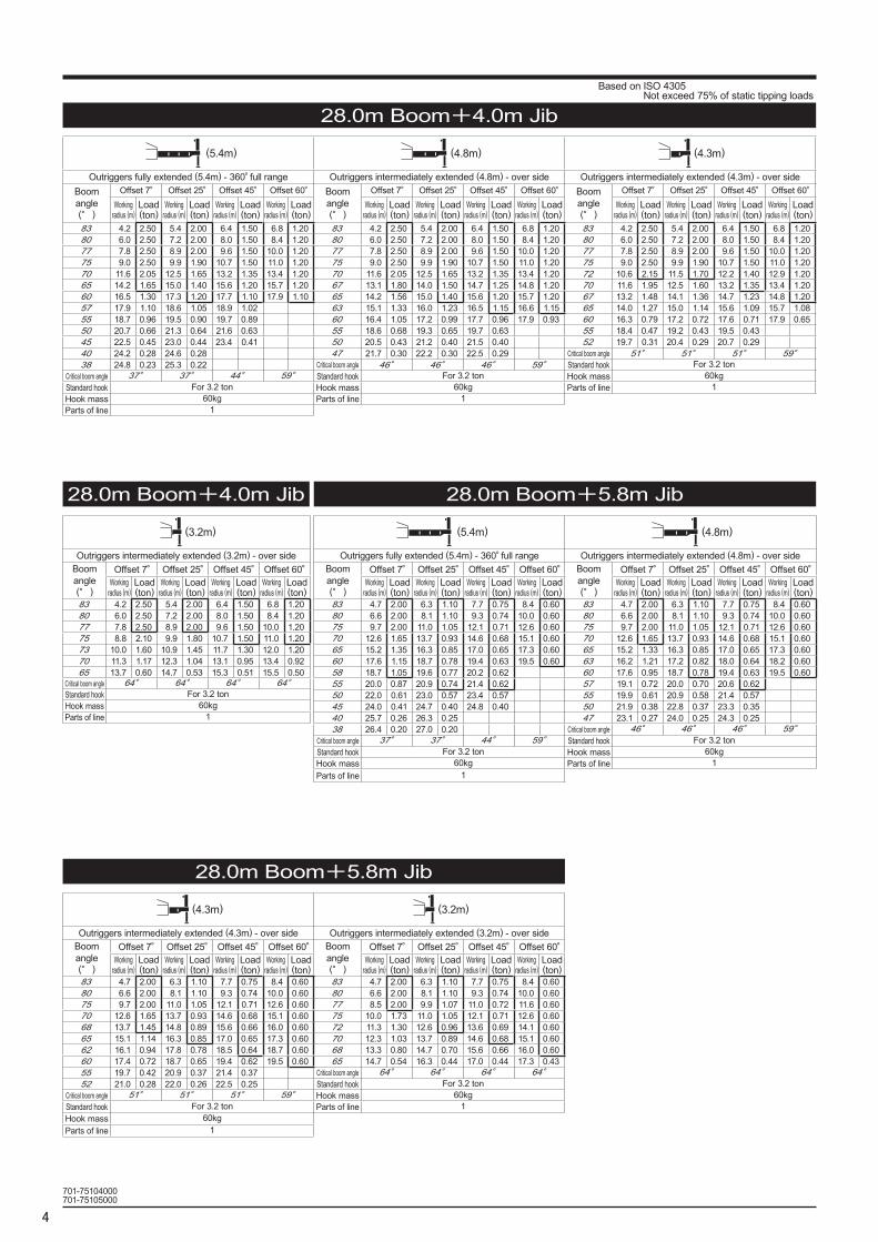
28.0m Boom+4.0m Jib
28.0m Boom+4.0m Jib
28.0m Boom+5.8m Jib
28.0m Boom+5.8m Jib
(5.4m) (4.8m) (4.3m)
Outriggers fully extended (5.4m) - 360°full range Outriggers intermediately extended (4.8m) - over side Outriggers intermediately extended (4.3m) - over sideBoom angle(°)
Offset 7° Offset 25° Offset 45° Offset 60° Boom angle(°)
Offset 7° Offset 25° Offset 45° Offset 60° Boom angle(°)
Offset 7° Offset 25° Offset 45° Offset 60°Working
radius (m)Load(ton)
Workingradius (m)
Load(ton)
Workingradius (m)
Load(ton)
Workingradius (m)
Load(ton)
Workingradius (m)
Load(ton)
Workingradius (m)
Load(ton)
Workingradius (m)
Load(ton)
Workingradius (m)
Load(ton)
Workingradius (m)
Load(ton)
Workingradius (m)
Load(ton)
Workingradius (m)
Load(ton)
Workingradius (m)
Load(ton)
83 4.2 2.50 5.4 2.00 6.4 1.50 6.8 1.20 83 4.2 2.50 5.4 2.00 6.4 1.50 6.8 1.20 83 4.2 2.50 5.4 2.00 6.4 1.50 6.8 1.2080 6.0 2.50 7.2 2.00 8.0 1.50 8.4 1.20 80 6.0 2.50 7.2 2.00 8.0 1.50 8.4 1.20 80 6.0 2.50 7.2 2.00 8.0 1.50 8.4 1.2077 7.8 2.50 8.9 2.00 9.6 1.50 10.0 1.20 77 7.8 2.50 8.9 2.00 9.6 1.50 10.0 1.20 77 7.8 2.50 8.9 2.00 9.6 1.50 10.0 1.2075 9.0 2.50 9.9 1.90 10.7 1.50 11.0 1.20 75 9.0 2.50 9.9 1.90 10.7 1.50 11.0 1.20 75 9.0 2.50 9.9 1.90 10.7 1.50 11.0 1.2070 11.6 2.05 12.5 1.65 13.2 1.35 13.4 1.20 70 11.6 2.05 12.5 1.65 13.2 1.35 13.4 1.20 72 10.6 2.15 11.5 1.70 12.2 1.40 12.9 1.2065 14.2 1.65 15.0 1.40 15.6 1.20 15.7 1.20 67 13.1 1.80 14.0 1.50 14.7 1.25 14.8 1.20 70 11.6 1.95 12.5 1.60 13.2 1.35 13.4 1.2060 16.5 1.30 17.3 1.20 17.7 1.10 17.9 1.10 65 14.2 1.56 15.0 1.40 15.6 1.20 15.7 1.20 67 13.2 1.48 14.1 1.36 14.7 1.23 14.8 1.2057 17.9 1.10 18.6 1.05 18.9 1.02 63 15.1 1.33 16.0 1.23 16.5 1.15 16.6 1.15 65 14.0 1.27 15.0 1.14 15.6 1.09 15.7 1.0855 18.7 0.96 19.5 0.90 19.7 0.89 60 16.4 1.05 17.2 0.99 17.7 0.96 17.9 0.93 60 16.3 0.79 17.2 0.72 17.6 0.71 17.9 0.6550 20.7 0.66 21.3 0.64 21.6 0.63 55 18.6 0.68 19.3 0.65 19.7 0.63 55 18.4 0.47 19.2 0.43 19.5 0.4345 22.5 0.45 23.0 0.44 23.4 0.41 50 20.5 0.43 21.2 0.40 21.5 0.40 52 19.7 0.31 20.4 0.29 20.7 0.2940 24.2 0.28 24.6 0.28 47 21.7 0.30 22.2 0.30 22.5 0.29 Critical boom angle 51° 51° 51° 59°38 24.8 0.23 25.3 0.22 Critical boom angle 46° 46° 46° 59° Standard hook For 3.2 ton
Critical boom angle 37° 37° 44° 59° Standard hook For 3.2 ton Hook mass 60kgStandard hook For 3.2 ton Hook mass 60kg Parts of line 1Hook mass 60kg Parts of line 1Parts of line 1
701-75104000701-75105000
(3.2m)
Outriggers intermediately extended (3.2m) - over sideBoom angle(°)
Offset 7° Offset 25° Offset 45° Offset 60°Working
radius (m)Load(ton)
Workingradius (m)
Load(ton)
Workingradius (m)
Load(ton)
Workingradius (m)
Load(ton)
83 4.2 2.50 5.4 2.00 6.4 1.50 6.8 1.2080 6.0 2.50 7.2 2.00 8.0 1.50 8.4 1.2077 7.8 2.50 8.9 2.00 9.6 1.50 10.0 1.2075 8.8 2.10 9.9 1.80 10.7 1.50 11.0 1.2073 10.0 1.60 10.9 1.45 11.7 1.30 12.0 1.2070 11.3 1.17 12.3 1.04 13.1 0.95 13.4 0.9265 13.7 0.60 14.7 0.53 15.3 0.51 15.5 0.50
Critical boom angle 64° 64° 64° 64°Standard hook For 3.2 tonHook mass 60kgParts of line 1
(4.3m) (3.2m)
Outriggers intermediately extended (4.3m) - over side Outriggers intermediately extended (3.2m) - over sideBoom angle(°)
Offset 7° Offset 25° Offset 45° Offset 60° Boom angle(°)
Offset 7° Offset 25° Offset 45° Offset 60°Working
radius (m)Load(ton)
Workingradius (m)
Load(ton)
Workingradius (m)
Load(ton)
Workingradius (m)
Load(ton)
Workingradius (m)
Load(ton)
Workingradius (m)
Load(ton)
Workingradius (m)
Load(ton)
Workingradius (m)
Load(ton)
83 4.7 2.00 6.3 1.10 7.7 0.75 8.4 0.60 83 4.7 2.00 6.3 1.10 7.7 0.75 8.4 0.6080 6.6 2.00 8.1 1.10 9.3 0.74 10.0 0.60 80 6.6 2.00 8.1 1.10 9.3 0.74 10.0 0.6075 9.7 2.00 11.0 1.05 12.1 0.71 12.6 0.60 77 8.5 2.00 9.9 1.07 11.0 0.72 11.6 0.6070 12.6 1.65 13.7 0.93 14.6 0.68 15.1 0.60 75 10.0 1.73 11.0 1.05 12.1 0.71 12.6 0.6068 13.7 1.45 14.8 0.89 15.6 0.66 16.0 0.60 72 11.3 1.30 12.6 0.96 13.6 0.69 14.1 0.6065 15.1 1.14 16.3 0.85 17.0 0.65 17.3 0.60 70 12.3 1.03 13.7 0.89 14.6 0.68 15.1 0.6062 16.1 0.94 17.8 0.78 18.5 0.64 18.7 0.60 68 13.3 0.80 14.7 0.70 15.6 0.66 16.0 0.6060 17.4 0.72 18.7 0.65 19.4 0.62 19.5 0.60 65 14.7 0.54 16.3 0.44 17.0 0.44 17.3 0.4355 19.7 0.42 20.9 0.37 21.4 0.37 Critical boom angle 64° 64° 64° 64°52 21.0 0.28 22.0 0.26 22.5 0.25 Standard hook For 3.2 ton
Critical boom angle 51° 51° 51° 59° Hook mass 60kgStandard hook For 3.2 ton Parts of line 1Hook mass 60kgParts of line 1
(5.4m) (4.8m)
Outriggers fully extended (5.4m) - 360°full range Outriggers intermediately extended (4.8m) - over sideBoom angle(°)
Offset 7° Offset 25° Offset 45° Offset 60° Boom angle(°)
Offset 7° Offset 25° Offset 45° Offset 60°Working
radius (m)Load(ton)
Workingradius (m)
Load(ton)
Workingradius (m)
Load(ton)
Workingradius (m)
Load(ton)
Workingradius (m)
Load(ton)
Workingradius (m)
Load(ton)
Workingradius (m)
Load(ton)
Workingradius (m)
Load(ton)
83 4.7 2.00 6.3 1.10 7.7 0.75 8.4 0.60 83 4.7 2.00 6.3 1.10 7.7 0.75 8.4 0.6080 6.6 2.00 8.1 1.10 9.3 0.74 10.0 0.60 80 6.6 2.00 8.1 1.10 9.3 0.74 10.0 0.6075 9.7 2.00 11.0 1.05 12.1 0.71 12.6 0.60 75 9.7 2.00 11.0 1.05 12.1 0.71 12.6 0.6070 12.6 1.65 13.7 0.93 14.6 0.68 15.1 0.60 70 12.6 1.65 13.7 0.93 14.6 0.68 15.1 0.6065 15.2 1.35 16.3 0.85 17.0 0.65 17.3 0.60 65 15.2 1.33 16.3 0.85 17.0 0.65 17.3 0.6060 17.6 1.15 18.7 0.78 19.4 0.63 19.5 0.60 63 16.2 1.21 17.2 0.82 18.0 0.64 18.2 0.6058 18.7 1.05 19.6 0.77 20.2 0.62 60 17.6 0.95 18.7 0.78 19.4 0.63 19.5 0.6055 20.0 0.87 20.9 0.74 21.4 0.62 57 19.1 0.72 20.0 0.70 20.6 0.6250 22.0 0.61 23.0 0.57 23.4 0.57 55 19.9 0.61 20.9 0.58 21.4 0.5745 24.0 0.41 24.7 0.40 24.8 0.40 50 21.9 0.38 22.8 0.37 23.3 0.3540 25.7 0.26 26.3 0.25 47 23.1 0.27 24.0 0.25 24.3 0.2538 26.4 0.20 27.0 0.20 Critical boom angle 46° 46° 46° 59°
Critical boom angle 37° 37° 44° 59° Standard hook For 3.2 tonStandard hook For 3.2 ton Hook mass 60kgHook mass 60kg Parts of line 1Parts of line 1
Based on ISO 4305 Not exceed 75% of static tipping loads
5
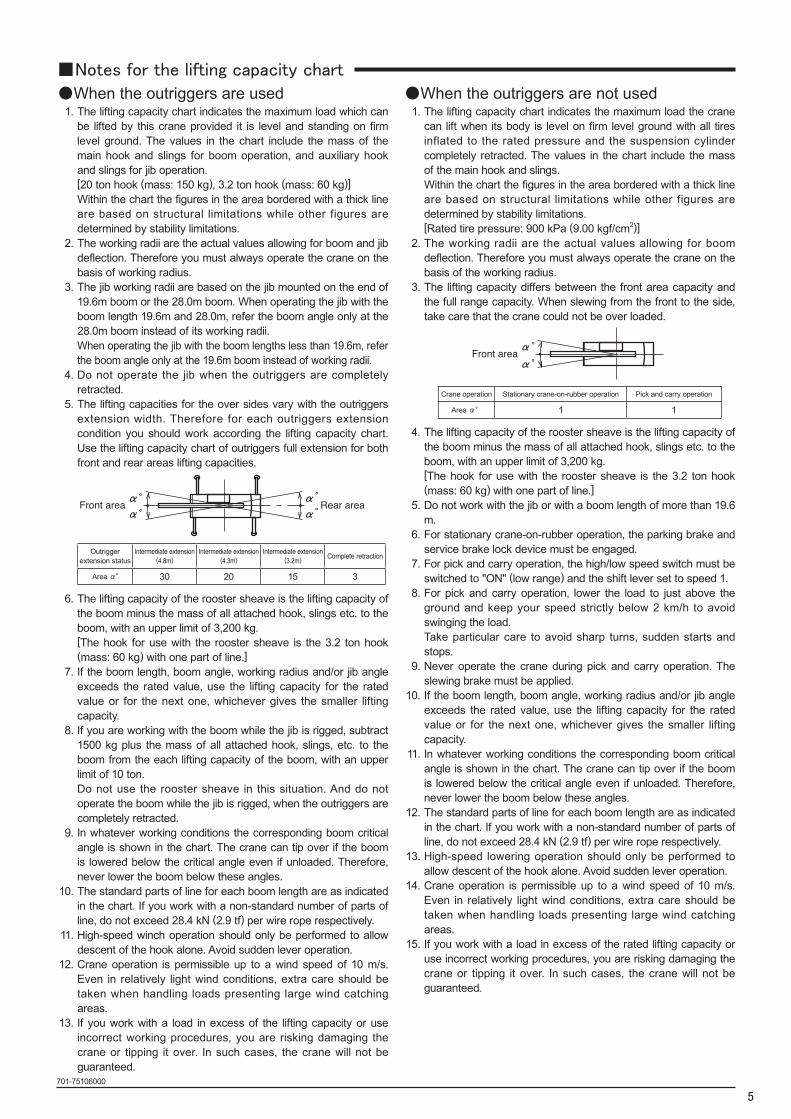
■Notes for the lifting capacity chart●When the outriggers are used 1. The lifting capacity chart indicates the maximum load which can
be lifted by this crane provided it is level and standing on firm level ground. The values in the chart include the mass of the main hook and slings for boom operation, and auxiliary hook and slings for jib operation.
[20 ton hook (mass: 150 kg), 3.2 ton hook (mass: 60 kg)] Within the chart the figures in the area bordered with a thick line
are based on structural limitations while other figures are determined by stability limitations.
2. The working radii are the actual values allowing for boom and jib deflection. Therefore you must always operate the crane on the basis of working radius.
3. The jib working radii are based on the jib mounted on the end of 19.6m boom or the 28.0m boom. When operating the jib with the boom length 19.6m and 28.0m, refer the boom angle only at the 28.0m boom instead of its working radii.
When operating the jib with the boom lengths less than 19.6m, refer the boom angle only at the 19.6m boom instead of working radii.
4. Do not operate the jib when the outriggers are completely retracted.
5. The lifting capacities for the over sides vary with the outriggers extension width. Therefore for each outriggers extension condition you should work according the lifting capacity chart. Use the lifting capacity chart of outriggers full extension for both front and rear areas lifting capacities.
Outrigger extension status
Intermediate extension(4.8m)
Intermediate extension(4.3m)
Intermediate extension(3.2m) Complete retraction
Area α° 30 20 15 3
6. The lifting capacity of the rooster sheave is the lifting capacity of the boom minus the mass of all attached hook, slings etc. to the boom, with an upper limit of 3,200 kg.
[The hook for use with the rooster sheave is the 3.2 ton hook (mass: 60 kg) with one part of line.]
7. If the boom length, boom angle, working radius and/or jib angle exceeds the rated value, use the lifting capacity for the rated value or for the next one, whichever gives the smaller lifting capacity.
8. If you are working with the boom while the jib is rigged, subtract 1500 kg plus the mass of all attached hook, slings, etc. to the boom from the each lifting capacity of the boom, with an upper limit of 10 ton.
Do not use the rooster sheave in this situation. And do not operate the boom while the jib is rigged, when the outriggers are completely retracted.
9. In whatever working conditions the corresponding boom critical angle is shown in the chart. The crane can tip over if the boom is lowered below the critical angle even if unloaded. Therefore, never lower the boom below these angles.
10. The standard parts of line for each boom length are as indicated in the chart. If you work with a non-standard number of parts of line, do not exceed 28.4 kN (2.9 tf) per wire rope respectively.
11. High-speed winch operation should only be performed to allow descent of the hook alone. Avoid sudden lever operation.
12. Crane operation is permissible up to a wind speed of 10 m/s. Even in relatively light wind conditions, extra care should be taken when handling loads presenting large wind catching areas.
13. If you work with a load in excess of the lifting capacity or use incorrect working procedures, you are risking damaging the crane or tipping it over. In such cases, the crane will not be guaranteed.
●When the outriggers are not used 1. The lifting capacity chart indicates the maximum load the crane
can lift when its body is level on firm level ground with all tires inflated to the rated pressure and the suspension cylinder completely retracted. The values in the chart include the mass of the main hook and slings.
Within the chart the figures in the area bordered with a thick line are based on structural limitations while other figures are determined by stability limitations.
[Rated tire pressure: 900 kPa (9.00 kgf/cm2)] 2. The working radii are the actual values allowing for boom
deflection. Therefore you must always operate the crane on the basis of the working radius.
3. The lifting capacity differs between the front area capacity and the full range capacity. When slewing from the front to the side, take care that the crane could not be over loaded.
Crane operation Stationary crane-on-rubber operation Pick and carry operation
Area α° 1 1
4. The lifting capacity of the rooster sheave is the lifting capacity of the boom minus the mass of all attached hook, slings etc. to the boom, with an upper limit of 3,200 kg.
[The hook for use with the rooster sheave is the 3.2 ton hook (mass: 60 kg) with one part of line.]
5. Do not work with the jib or with a boom length of more than 19.6 m.
6. For stationary crane-on-rubber operation, the parking brake and service brake lock device must be engaged.
7. For pick and carry operation, the high/low speed switch must be switched to "ON" (low range) and the shift lever set to speed 1.
8. For pick and carry operation, lower the load to just above the ground and keep your speed strictly below 2 km/h to avoid swinging the load.
Take particular care to avoid sharp turns, sudden starts and stops.
9. Never operate the crane during pick and carry operation. The slewing brake must be applied.
10. If the boom length, boom angle, working radius and/or jib angle exceeds the rated value, use the lifting capacity for the rated value or for the next one, whichever gives the smaller lifting capacity.
11. In whatever working conditions the corresponding boom critical angle is shown in the chart. The crane can tip over if the boom is lowered below the critical angle even if unloaded. Therefore, never lower the boom below these angles.
12. The standard parts of line for each boom length are as indicated in the chart. If you work with a non-standard number of parts of line, do not exceed 28.4 kN (2.9 tf) per wire rope respectively.
13. High-speed lowering operation should only be performed to allow descent of the hook alone. Avoid sudden lever operation.
14. Crane operation is permissible up to a wind speed of 10 m/s. Even in relatively light wind conditions, extra care should be taken when handling loads presenting large wind catching areas.
15. If you work with a load in excess of the rated lifting capacity or use incorrect working procedures, you are risking damaging the crane or tipping it over. In such cases, the crane will not be guaranteed.
701-75106000
6
■WORKING RANGE
701-75107001
7
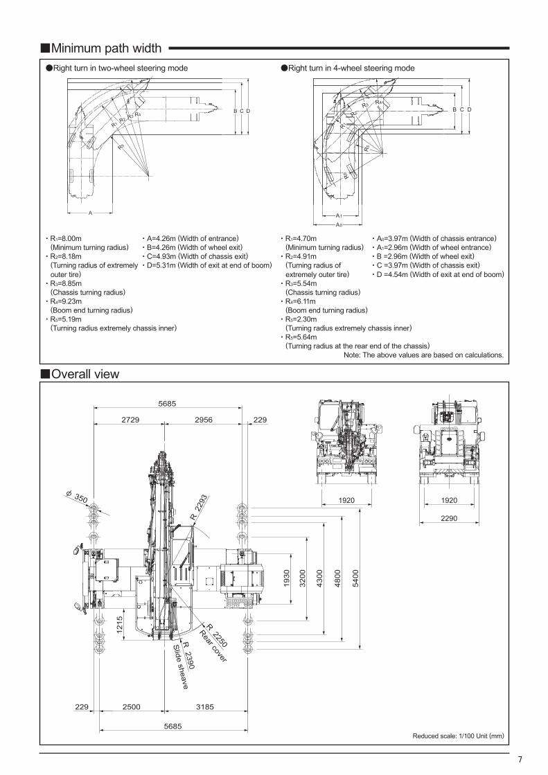
●Right turn in two-wheel steering mode ●Right turn in 4-wheel steering mode
A A1
R6
A0
・R1=8.00m ・A=4.26m (Width of entrance) ・R1=4.70m ・A0=3.97m (Width of chassis entrance)(Minimum turning radius) ・B=4.26m (Width of wheel exit) (Minimum turning radius) ・A1=2.96m (Width of wheel entrance)
・R2=8.18m ・C=4.93m (Width of chassis exit) ・R2=4.91m ・B =2.96m (Width of wheel exit)(Turning radius of extremely outer tire)
・D=5.31m (Width of exit at end of boom) (Turning radius of extremely outer tire)
・C =3.97m (Width of chassis exit)・D =4.54m (Width of exit at end of boom)
・R3=8.85m ・R3=5.54m(Chassis turning radius) (Chassis turning radius)
・R4=9.23m ・R4=6.11m(Boom end turning radius) (Boom end turning radius)
・R5=5.19m ・R5=2.30m(Turning radius extremely chassis inner) (Turning radius extremely chassis inner)
・R5=5.64m(Turning radius at the rear end of the chassis)
Note: The above values are based on calculations.
■Minimum path width
■Overall view
1920
2290
1920
2293
R
1215
1930
3200
4300
4800
5400
229 31852500
2292729 2956
5685
φ 350
R 2250R 2390
5685
Rear cover
Slide sheave
Reduced scale: 1/100 Unit (mm)
8
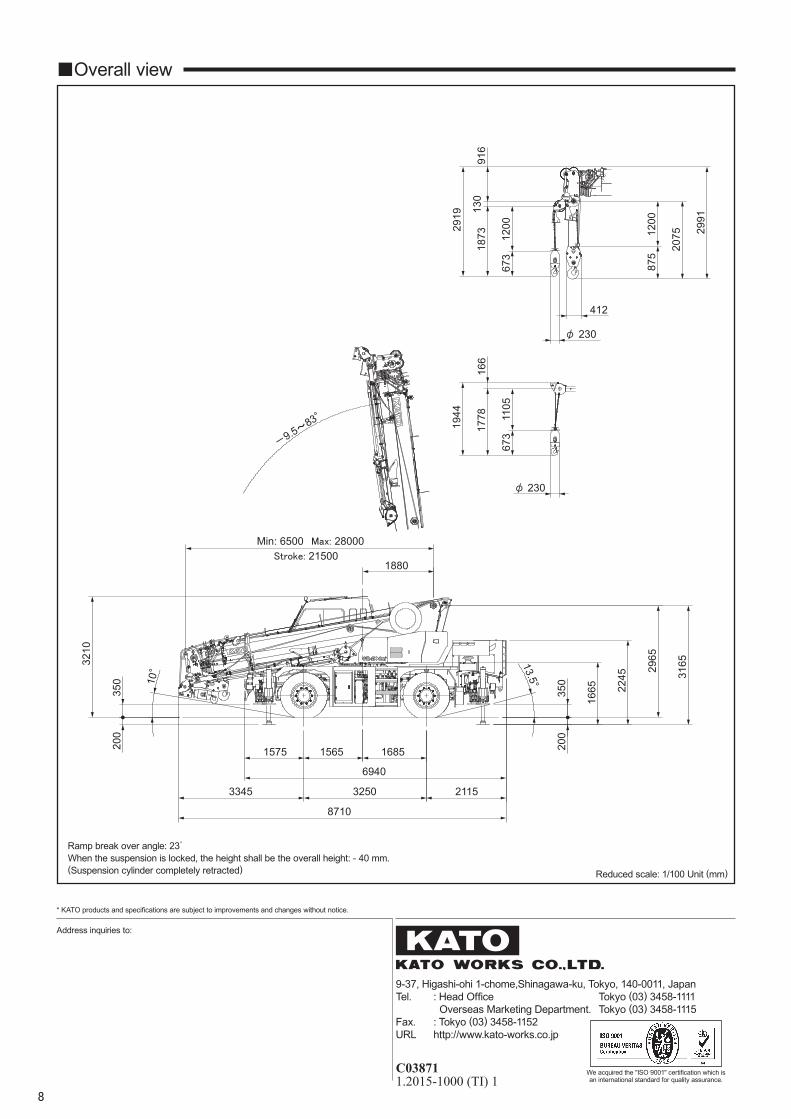
■Overall view
3165
200
350
1665 22
45
200
350
1880
168515651575
32503345
2965
2115
8710
3210
13.5°
Stroke: 21500
10°
Min: 6500
-9.5~
83°
Max: 28000
6940
166
673
φ 23011
05
1778
1944
1200
875
2075
916
130
673
1200
1873
2919
φ 230
2991
412
9-37, Higashi-ohi 1-chome,Shinagawa-ku, Tokyo, 140-0011, JapanTel. : Head Office Tokyo (03) 3458-1111 Overseas Marketing Department. Tokyo (03) 3458-1115Fax. : Tokyo (03) 3458-1152URL http://www.kato-works.co.jp
C038711.2015-1000 (TI) 1
* KATO products and specifications are subject to improvements and changes without notice.
Address inquiries to:
We acquired the "ISO 9001" certification which isan international standard for quality assurance.
Ramp break over angle: 23゚When the suspension is locked, the height shall be the overall height: - 40 mm.(Suspension cylinder completely retracted) Reduced scale: 1/100 Unit (mm)