Embed Size (px)
Citation preview

Carestream Gel Logic 2200 PRO
User’s Guide
IB5438234 Rev A 04/10

© Copyright Carestream Health, Incorporated, 2009-2010. All rights are reserved. No section of this manual may be photocopied, reproduced, translated to another language, stored in a retrieval system, or transmitted in any form without the prior written consent of Carestream Health, Incorporated.
The information contained in this manual is subject to change without notice. Carestream Health, Incor-porated. makes no warranty of any kind with regard to this written material.Carestream Health, Incor-porated assumes no responsibility for any errors that may appear in this document.
Disclaimer: While the Carestream Gel Logic system can be used for molecular imaging of materials, a purchaser should be aware that the methods of preparing and viewing the materials for molecular im-aging may be subject to various patent rights.
Apple, Macintosh, Mac, Mac OS, and OS X are registered trademarks and Safari is a trademark of Ap-ple Computer, Incorporated.Coomassie is a registered trademark of Imperial Chemical Industries, Limited.IEEE 1394 is a trademark of The Institute of Electrical and Electronics Engineers Standards Associa-tion.Internet Explorer, Windows, Windows 7, Windows Vista, and Windows XP are registered trademarks of Microsoft Corporation.Norton Utilities and Norton Antivirus are registered trademarks of Symantic Corporation.SYPRO and SYBR are trademarks of Molecular Probes, Incorporated.
All other products or name brands are trademarks of their respective holders.
Should you have any questions concerning this product, contact Technical Support, Carestream Mo-lecular Imaging, Carestream Health, Incorporated, 4 Research Drive, Woodbridge, CT 06525 USA.
For laboratory research use only. Not suitable for human or animal diagnostic or therapeutic use.

Table o
f Co
ntents
Table of Contents
Introduction . . . . . . . . . . . . . . . . . . . . . . . . . . . . . . . . . . . . . . . . 1-1About the User’s Guide . . . . . . . . . . . . . . . . . . . . . . . . . . . . . . . . . . . . . . . . . . . . . . 1-2
Conventions . . . . . . . . . . . . . . . . . . . . . . . . . . . . . . . . . . . . . . . . . . . . . . . . . . . . . . . . . . 1-2
Navigating Through the User’s Guide . . . . . . . . . . . . . . . . . . . . . . . . . . . . . . . . . . 1-3
Package Contents. . . . . . . . . . . . . . . . . . . . . . . . . . . . . . . . . . . . . . . . . . . . . . . . . . . 1-4
System Requirements . . . . . . . . . . . . . . . . . . . . . . . . . . . . . . . . . . . . . . . . . . . . . . . 1-5
Minimum System Requirements—Windows . . . . . . . . . . . . . . . . . . . . . . . . . . . . . . . . . 1-5
Minimum System Requirements—Macintosh . . . . . . . . . . . . . . . . . . . . . . . . . . . . . . . . 1-5
Technical Support . . . . . . . . . . . . . . . . . . . . . . . . . . . . . . . . . . . . . . . . . . . . . . . . . . 1-6
Carestream Molecular Imaging Technical Support . . . . . . . . . . . . . . . . . . . . . . . . . . . . 1-6
Registering Your System. . . . . . . . . . . . . . . . . . . . . . . . . . . . . . . . . . . . . . . . . . . . . 1-7
System Overview . . . . . . . . . . . . . . . . . . . . . . . . . . . . . . . . . . . . 2-1The Carestream GL2200 PRO Imaging Cabinet. . . . . . . . . . . . . . . . . . . . . . . . . . . 2-2
The Carestream GL2200 PRO Acquire Software . . . . . . . . . . . . . . . . . . . . . . . . . . 2-6
The GL2200 PRO Image Preview . . . . . . . . . . . . . . . . . . . . . . . . . . . . . . . . . . . . . . . . . 2-8
Capture Section of the GL2200 PRO Acquire Window. . . . . . . . . . . . . . . . . . . . . . . . . 2-9
Exposure Section of the GL2200 PRO Acquire Window . . . . . . . . . . . . . . . . . . . . . . 2-11
Buttons Section of the GL2200 PRO Acquire Window . . . . . . . . . . . . . . . . . . . . . . . . 2-13
Lens Section of the GL2200 PRO Acquire Windows . . . . . . . . . . . . . . . . . . . . . . . . . 2-13
Illumination Section of the GL2200 PRO Acquire Windows . . . . . . . . . . . . . . . . . . . 2-14
Emission Filter Section of the GL2200 PRO Acquire Windows . . . . . . . . . . . . . . . . . 2-15
The GL2200 PRO Preferences Dialog Box . . . . . . . . . . . . . . . . . . . . . . . . . . . . . . . . . 2-16
Setting Up Your System . . . . . . . . . . . . . . . . . . . . . . . . . . . . . . . 3-1Environmental Requirements . . . . . . . . . . . . . . . . . . . . . . . . . . . . . . . . . . . . . . . . . 3-2
Electrical Requirements. . . . . . . . . . . . . . . . . . . . . . . . . . . . . . . . . . . . . . . . . . . . . . 3-2
Space Requirements . . . . . . . . . . . . . . . . . . . . . . . . . . . . . . . . . . . . . . . . . . . . . . . . 3-2
Installing the Carestream Molecular Imaging Software—Windows . . . . . . . . . . . 3-3
Uninstalling a Previous Version of MI or 1D Software—Windows . . . . . . . . . . . . . . . 3-3
i
ii
Carestream Molecular Imaging Software Installation—Windows. . . . . . . . . . . . . . . . . 3-5
Copy Protection Device Installation—Windows . . . . . . . . . . . . . . . . . . . . . . . . . . . . . . 3-6
Windows Power Settings . . . . . . . . . . . . . . . . . . . . . . . . . . . . . . . . . . . . . . . . . . . . . . . . 3-7
Installing the Carestream Molecular Imaging Software—Macintosh. . . . . . . . . . . 3-8
Uninstalling a Previous Version of MI or 1D Software—Macintosh. . . . . . . . . . . . . . . 3-9
Carestream Molecular Imaging Software Installation—Macintosh . . . . . . . . . . . . . . . 3-10
Copy Protection Device Installation—Macintosh . . . . . . . . . . . . . . . . . . . . . . . . . . . . 3-11
Macintosh Power Settings. . . . . . . . . . . . . . . . . . . . . . . . . . . . . . . . . . . . . . . . . . . . . . . 3-12
Launching Carestream Molecular Imaging Software for the First Time . . . . . . . 3-13
Carestream MI Image Database . . . . . . . . . . . . . . . . . . . . . . . . . . . . . . . . . . . . . . 3-16
Installing the Carestream Gel Logic 2200 PRO Imaging System. . . . . . . . . . . . . 3-20
Installing the GL2200 PRO Imaging Hardware . . . . . . . . . . . . . . . . . . . . . . . . . . . . . . 3-20
Carestream Gel Logic 2200 PRO Accessories Installation. . . . . . . . . . . . . . . . . . 3-23
Installing the White Light Transilluminator Module (Optional Accessory) . . . . . . . . 3-23
Installing the UV Epi-illumination Light Module (Optional Accessory). . . . . . . . . . . 3-25
Installing the UV Safety Shield . . . . . . . . . . . . . . . . . . . . . . . . . . . . . . . . . . . . . . . . . . 3-27
Launching Carestream Molecular Imaging Software with your Carestream
Gel Logic 2200 PRO Imaging System . . . . . . . . . . . . . . . . . . . . . . . . . . . . . . . . . 3-28
Installing Emission Filters. . . . . . . . . . . . . . . . . . . . . . . . . . . . . . . . . . . . . . . . . . . 3-30
Focusing the Camera . . . . . . . . . . . . . . . . . . . . . . . . . . . . . . . . . . . . . . . . . . . . . . . 3-32
Capturing Images . . . . . . . . . . . . . . . . . . . . . . . . . . . . . . . . . . . . 4-1Launching Carestream Molecular Imaging Software and the Gel Logic 2200
PRO Acquire Window. . . . . . . . . . . . . . . . . . . . . . . . . . . . . . . . . . . . . . . . . . . . . . . 4-2
Preparing for Image Capture . . . . . . . . . . . . . . . . . . . . . . . . . . . . . . . . . . . . . . . . . . 4-4
Previewing and Capturing Images. . . . . . . . . . . . . . . . . . . . . . . . . . . . . . . . . . . . . . 4-5
Custom Capture Settings . . . . . . . . . . . . . . . . . . . . . . . . . . . . . . . . . . . . . . . . . . . . . 4-9
Saving Custom User Settings . . . . . . . . . . . . . . . . . . . . . . . . . . . . . . . . . . . . . . . . . . . . . 4-9
Updating Custom User Settings . . . . . . . . . . . . . . . . . . . . . . . . . . . . . . . . . . . . . . . . . . 4-10
Deleting Custom User Settings. . . . . . . . . . . . . . . . . . . . . . . . . . . . . . . . . . . . . . . . . . . 4-10
Using the Focusing Tool . . . . . . . . . . . . . . . . . . . . . . . . . . . . . . . . . . . . . . . . . . . . 4-11
Applying an Illumination Reference . . . . . . . . . . . . . . . . . . . . . . . . . . . . . . . . . . . 4-12
Adding an Annotation Bar to the Printed Image . . . . . . . . . . . . . . . . . . . . . . . . . . 4-13
Using the Transilluminator for Non-Imaging Applications . . . . . . . . . . . . . . . . . 4-14
Table o
f Co
ntents
Maintaining Your System . . . . . . . . . . . . . . . . . . . . . . . . . . . . . . 5-1Maintaining Your Carestream GL2200 PRO Imaging Cabinet . . . . . . . . . . . . . . . 5-2
Cleaning the Cabinet. . . . . . . . . . . . . . . . . . . . . . . . . . . . . . . . . . . . . . . . . . . . . . . . . . . . 5-2
Cleaning Filters. . . . . . . . . . . . . . . . . . . . . . . . . . . . . . . . . . . . . . . . . . . . . . . . . . . . . . . . 5-3
Cleaning the White/Black Epi-illumination Pads . . . . . . . . . . . . . . . . . . . . . . . . . . . . . . 5-3
Repairing Your Carestream Gel Logic 2200 PRO Imaging System. . . . . . . . . . . . 5-4
Replacing the UV Transilluminator Bulbs . . . . . . . . . . . . . . . . . . . . . . . . . . . . . . . . . . . 5-4
Replacing the White Light Epi-Illumination Bulbs . . . . . . . . . . . . . . . . . . . . . . . . . . . . 5-6
Replacing the UV Epi-Illumination Module Bulbs (Optional Accessory). . . . . . . . . . . 5-8
Replacing the UV Transilluminator Platen. . . . . . . . . . . . . . . . . . . . . . . . . . . . . . . . . . 5-10
Troubleshooting the System . . . . . . . . . . . . . . . . . . . . . . . . . . . 6-1Technical Support . . . . . . . . . . . . . . . . . . . . . . . . . . . . . . . . . . . . . . . . . . . . . . . . . . 6-2
Carestream Molecular Imaging Technical Support . . . . . . . . . . . . . . . . . . . . . . . . . . . . 6-2
Common Instrument Problems . . . . . . . . . . . . . . . . . . . . . . . . . . . . . . . . . . . . . . . . 6-3
Common Image Problems . . . . . . . . . . . . . . . . . . . . . . . . . . . . . . . . . . . . . . . . . . . . 6-5
Common Software Problems. . . . . . . . . . . . . . . . . . . . . . . . . . . . . . . . . . . . . . . . . . 6-7
Warranty . . . . . . . . . . . . . . . . . . . . . . . . . . . . . . . . . . . . . . . . . . W-1Limited Warranty Period. . . . . . . . . . . . . . . . . . . . . . . . . . . . . . . . . . . . . . . . . . . . W-1
Days and Hours of Coverage. . . . . . . . . . . . . . . . . . . . . . . . . . . . . . . . . . . . . . . . . W-1
Warranty Repair Coverage . . . . . . . . . . . . . . . . . . . . . . . . . . . . . . . . . . . . . . . . . . W-1
Limitations. . . . . . . . . . . . . . . . . . . . . . . . . . . . . . . . . . . . . . . . . . . . . . . . . . . . . . . W-2
How to Obtain Service . . . . . . . . . . . . . . . . . . . . . . . . . . . . . . . . . . . . . . . . . . . . . W-3
General Instructions for Cleaning and Decontamination For Return of
the GL2200 PRO . . . . . . . . . . . . . . . . . . . . . . . . . . . . . . . . . . . . . . . . . . . . . . . . . . W-4
General Cleaning Procedure . . . . . . . . . . . . . . . . . . . . . . . . . . . . . . . . . . . . . . . . . . . . . W-4
Radiological Decontamination Procedure . . . . . . . . . . . . . . . . . . . . . . . . . . . . . . . . . . W-4
Repackaging the GL2200 PRO . . . . . . . . . . . . . . . . . . . . . . . . . . . . . . . . . . . . . . . W-6
Regulatory Information . . . . . . . . . . . . . . . . . . . . . . . . . . . . . . . . . . . . . . . . . . . . . W-7
Appendix A: Parts and Accessories . . . . . . . . . . . . . . . . . . . . . A-1
iii

iv

Introd
uction
1
Introduction
Thank you for purchasing the Carestream Gel Logic 2200 PRO Imaging System (GL2200 PRO). The GL2200 PRO, in combination with Carestream Molecular Imaging Software (Carestream MI), is a multi-purpose system for imaging of fluorescence, chemiluminescence, and chromogenic gels and blots. The GL2200 PRO detects fluorescent signals at picomole to femtomole levels on gels and blots and is as sensitive as autoradiography films for most chemiluminescence applications.
The affordable system combines a thermoelectrically cooled charged-coupled device (CCD) camera, combined with a 6X zoom lens, captures 16-bit images that can be accumulated to n-bit files at a pixel density of 1708 x 1280. This generates an image with a resolution of 28 microns/pixel at full zoom. Within Carestream MI, the Gel Logic 2200 PRO Acquire window accumulates and displays multiple image captures so you can optimize the contrast of your image.
The GL2200 PRO’s fully automated cabinet integrates both transillumination and epi-illumination for both UV and white light excitation allowing you to image a wide variety of fluorescent and colorimetric samples. The broadband UV excitation (peak at 306 nm) provides for the detection of a broad range of fluorescent dyes including ethidium bromide, SYBR Green and SYBR Red. The white light illumination is ideal for illumination of protein gels, blots and plates.
The GL2200 PRO Acquire Software module, running within Carestream MI allows you to:
✔ Image electrophoresis gels, microtiter plates, and colony and plaque assays.
✔ Analyze your image for molecular weight, mass, optical density, and intensity measurements.
✔ Annotate and prepare your images for publication.
✔ Generate hard copy prints at a fraction of the cost of instant photography.
✔ Easily share or transmit image files over local or worldwide networks.
Carestream Molecular Imaging is dedicated to providing cutting edge imaging product systems for scientific research applications. For more information on-screen products for scientific imaging applications, please visit us on the worldwide web at mi.carestreamhealth.com.
1-1
1-2
About the User’s Guide
The Carestream Gel Logic 2200 PRO User’s Guide provides you with all of the information you need to capture images. It is designed to be used in conjunction with the Carestream Molecular Imaging Software User’s Guide.
If you are like most users, you will want to get started right away; but before you do, you need to have basic computer skills including:
✔ Launching applications
✔ Using a mouse
✔ Using pop-up menus
✔ Selecting and editing text
✔ Saving and printing your work
✔ Dragging and dropping objects
Refer to your computer manual to become familiar with the skills listed above.
Conventions
This User’s Guide utilizes the following conventions:
✔ Menus and dialog boxes are displayed using Windows XP and may appear differently on your screen. Any significant differences in commands between Macintosh and Windows platforms are noted in the text.
✔ Menu commands, tool names, and window names are shown capitalized.
✔ Warnings, tips, and notes appear in the text like this:
☞ NOTE: Carestream Molecular Imaging provides maximum performance products.
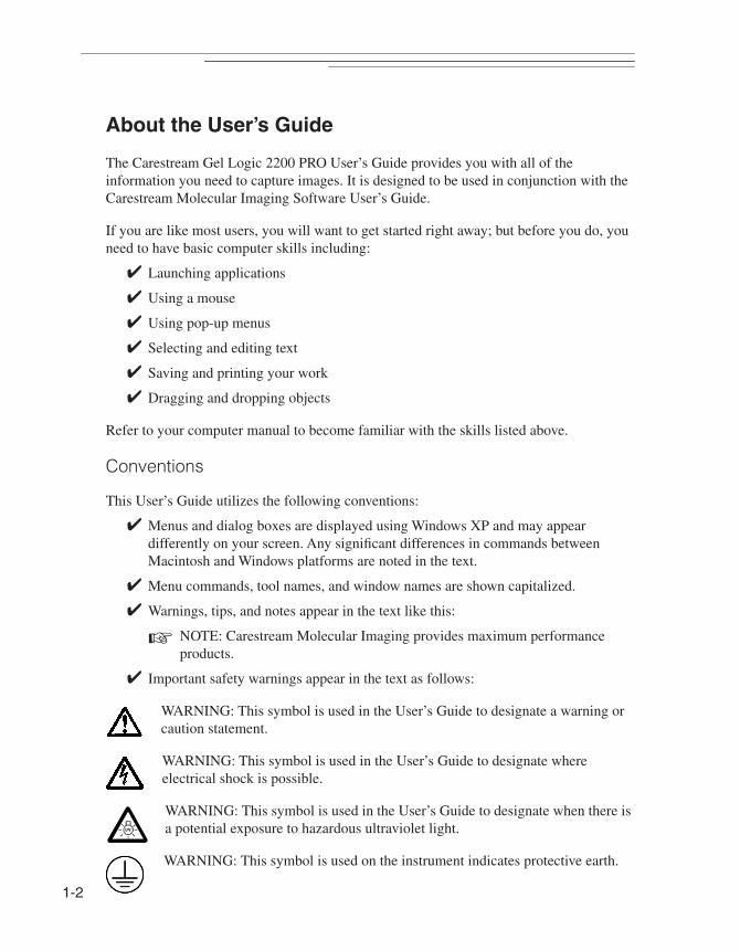
✔ Important safety warnings appear in the text as follows:
WARNING: This symbol is used in the User’s Guide to designate a warning or caution statement.
WARNING: This symbol is used in the User’s Guide to designate where electrical shock is possible.
WARNING: This symbol is used in the User’s Guide to designate when there is a potential exposure to hazardous ultraviolet light.
WARNING: This symbol is used on the instrument indicates protective earth.

Introd
uction
1
Navigating Through the User’s Guide
The Carestream Gel Logic 2200 PRO Imaging System User’s Guide is divided into the chapters listed below:
✔ Chapter 1: Introduction gets you started by describing system components and requirements.
✔ Chapter 2: System Overview details the instrument and software related to GL2200 PRO.
✔ Chapter 3: Setting Up Your System walks you through the installation process.
✔ Chapter 4: Capturing Images describes how to use the GL2200 PRO to capture images.
✔ Chapter 5: Maintaining Your System describes how to care for and maintain your GL2200 PRO.
✔ Chapter 6: Troubleshooting offers tips if you encounter any problems with your system.
✔ Warranty reviews the warranty and repair coverage provided by Carestream Health, Inc.
✔ Appendix A: Related Products provides you information on accessories and replacement parts for your GL2200 PRO.
1-3
1-4
Package Contents
When unpacking your Carestream Gel Logic 2200 PRO Imaging System, please take a moment to ensure that all the necessary parts have been received. Your package should contain:
Carestream Gel Logic 2200 PRO Hardware (1)
✔ Carestream GL2200 PRO Imaging Cabinet with the Carestream GL2200 PRO Camera
✔ White Light Transilluminator Module
✔ GL PRO Camera/Computer Interface Ethernet Cable(s)
✔ 590 nm Filter, 55 mm
✔ Filter Tool
✔ Carestream GL2200 PRO User’s Guide
✔ White/Black Epi-Illumination Pad Set
✔ Gel Cutting Tray
✔ Ethernet Switch*
✔ UV Shield (optional accessory)*
✔ UV Epi-illumination Modules, 370 nm, 302 nm, or 254 nm (optional accessories)*
Carestream Molecular Imaging Software (1)
✔ Carestream Molecular Imaging Software CD (1)
✔ Carestream Molecular Imaging Software User’s Guide (3)
✔ Copy Protection Device (3)
✔ Registration Card
(or)
✔ Carestream Molecular Imaging Software Network Edition (Custom Package)
• Carestream Molecular Imaging Software Network Edition CD (1)
• Carestream Molecular Imaging Software Network Edition Administrator’s Manual (1)
• Carestream Molecular Imaging Software User’s Guide (3)
* Depending on the system configuration you purchased.
-5
Introd
uction
1
1
System Requirements
These are minimum specifications, however, we cannot ensure that all hardware and software systems are compatible. For optimal performance, we strongly recommend dedicating a computer exclusively for use with your imaging system.
Minimum System Requirements—Windows✔ Personal computer with a USB port and an Ethernet port
✔ Pentium IV (or equivalent) processor greater than 2 GHz is recommended
✔ Windows XP (Service Pack 3 or greater), Windows Vista Business (Service Pack 1 or greater) or Windows 7 (32-bit only) operating system software
☞ NOTE: Check your operating system version by right-clicking on the My Computer icon and then on Properties.
✔ 17 in. display—1280 x 1024 resolution
✔ 2 GB recommended
✔ Minimum 20 GB of available hard disk space
✔ CD drive, CD-RW drive recommended
✔ TCP/IP
✔ Internet Explorer 7.0 or greater web browser
Minimum System Requirements—Macintosh✔ Intel Macintosh with a USB port and an ethernet port
✔ Mac OS (10.5 or greater)
☞ NOTE: Check your operating system version by selecting About This Mac under the Apple menu item.
✔ 17 in. display—1280 x 1024 resolution
✔ 2 GB recommended
✔ Minimum of 20 GB of available hard disk space
✔ CD drive, CD-RW drive recommended
✔ TCP/IP
✔ Safari 4.0 or greater web browser

1-6
Technical Support
For technical support, contact Carestream Molecular Imaging Technical Support or your Carestream Molecular Imaging dealer. For up to date dealer information, visit our WEB site at mi.carestreamhealth.com. When contacting technical support, please have the following information available:
✔ The serial number of your GL2200 PRO located on the back of the unit.
✔ The serial number of your GL2200 PRO Camera—press Control and T buttons simultaneously when the GL2200 PRO Acquire window is displayed.
✔ The serial number and version number of your Carestream MI software.
☞ NOTE: With the software running, select About MI under the Help menu (Windows) or select About MI under the Apple menu item (Macintosh).
✔ The type of computer you are using (make, model).
✔ Operating system software version.
☞ NOTE: Check your operating system version by right-clicking on the My Computer icon and then on Properties (Windows) or select About This Mac under the Apple menu item (Macintosh).
✔ The type of image you are capturing or analyzing.
✔ The problem you are having and what you were doing when the problem occurred. Please note the exact wording of any error messages, including any error numbers displayed.
Carestream Molecular Imaging Technical Support
Contact Carestream Molecular Imaging Technical Support by:
✔ Utilizing our World Wide Web support pages at:
mi.carestreamhealth.com
✔ Calling Carestream Molecular Imaging Technical Support at:
In US and Canada 877-747-4357 or world wide 203-786-5657, between the hours of 8:00 a.m. and 6:00 p.m. (Eastern Standard Time) Monday through Friday
✔ E-mailing Carestream Molecular Imaging Technical Support at:
✔ Faxing Carestream Molecular Imaging Technical Support at:
203-786-5656
Introd
uction
1
Registering your System
It is important for you to register your Carestream Molecular Imaging System. Once registered, you will receive information on maintenance releases, upgrades, and exciting new products. Register by filling out and returning the registration card included with your software package.
You can also register any time on-line. If your computer connects to the Internet, select Register MI from the Help menu (Windows) or Register Online from the Apple menu item (Macintosh).
1-7

1-8

System
Overview
2
System Overview
This section provides an overview of the Carestream Gel Logic 2200 PRO Imaging System (GL2200 PRO). You will review the principles of operation and get a better understanding of the critical components—the Carestream GL2200 PRO Imaging Cabinet with accessories and the Carestream GL2200 PRO Acquire Software.
2-1
2-2
The Carestream GL2200 PRO Imaging Cabinet
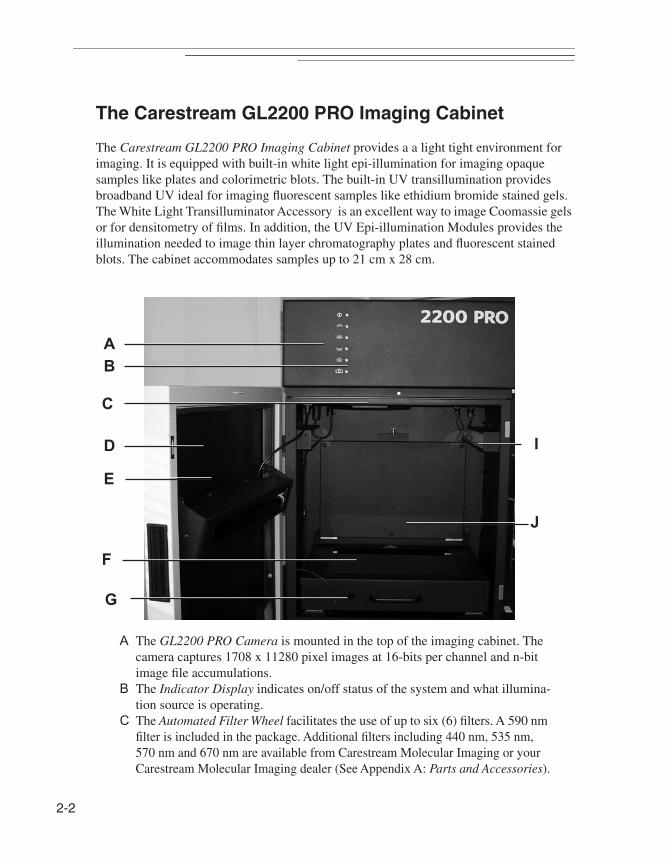
The Carestream GL2200 PRO Imaging Cabinet provides a a light tight environment for imaging. It is equipped with built-in white light epi-illumination for imaging opaque samples like plates and colorimetric blots. The built-in UV transillumination provides broadband UV ideal for imaging fluorescent samples like ethidium bromide stained gels. The White Light Transilluminator Accessory is an excellent way to image Coomassie gels or for densitometry of films. In addition, the UV Epi-illumination Modules provides the illumination needed to image thin layer chromatography plates and fluorescent stained blots. The cabinet accommodates samples up to 21 cm x 28 cm.
A The GL2200 PRO Camera is mounted in the top of the imaging cabinet. The camera captures 1708 x 11280 pixel images at 16-bits per channel and n-bit image file accumulations.
B The Indicator Display indicates on/off status of the system and what illumina-tion source is operating.
C The Automated Filter Wheel facilitates the use of up to six (6) filters. A 590 nm filter is included in the package. Additional filters including 440 nm, 535 nm, 570 nm and 670 nm are available from Carestream Molecular Imaging or your Carestream Molecular Imaging dealer (See Appendix A: Parts and Accessories).
A
B
C
G
I
E
D
F
J
System
Overview
2
D The Imaging Cabinet Door accesses the area under the camera, which accom-modates the imaging of samples up to 21 x 28 cm.
E The UV Epi-illumination Light is an optional accessory. The light accessory is easily installed inside the GL2200 PRO cabinet door. Wavelengths available include 370 nm, 306 nm or 254 nm.
DANGER—Ultraviolet radiation emitted from this product. Avoid exposure. ALWAYS WEAR PROTECTIVE CLOTHING. EXPOSURE MAY CAUSE PREMATURE AGING OF THE SKIN AND CANCER. ALWAYS WEAR PROTECTIVE EYEWEAR; FAILURE TO DO SO MAY RESULT IN SEVERE BURNS OR LONG TERM INJURY TO EYE. Never look directly into the lamp. Exposure can cause eye and skin allergy and allergic reactions. Medications or cosmetics may increase your sensitivity to ultraviolet radiation. Consult physician before operating this product if you are using medications or have a history of skin problems or believe yourself especially sensitive to sunlight. For Laboratory Use Only.
The UV source does not operate when the door is open. Do not attempt to override this feature.
F The UV Transilluminator provides a uniform intense (306 nm peak emission) source of ultraviolet radiation. The sample work area is 35 cm by 47 cm, how-ever the UV image area is limited to 24.5 cm x 33 cm.
DANGER—Ultraviolet radiation emitted from this product. Avoid exposure. ALWAYS WEAR PROTECTIVE CLOTHING. EXPOSURE MAY CAUSE PREMATURE AGING OF THE SKIN AND CANCER. ALWAYS WEAR PROTECTIVE EYEWEAR; FAILURE TO DO SO MAY RESULT IN SEVERE BURNS OR LONG TERM INJURY TO EYE. Never look directly into the lamp. Exposure can cause eye and skin allergy and allergic reactions. Medications or cosmetics may increase your sensitivity to ultraviolet radiation. Consult physician before operating this product if you are using medications or have a history of skin problems or believe yourself especially sensitive to sunlight. For Laboratory Use Only.
The UV source does not operate when the door is open. Do not attempt to override this feature.
Discontinue use if the Platen is damaged or broken.
G The UV Switch turns on the UV transilluminator only when the optional UV Safety Shield is in place and UV Trans is selected in the GL2200 PRO Acquire window. Use this feature to visualize or excise bands.
H The UV Safety Shield (not shown, optional accessory) is designed to limit your
2-3
2-4
exposure to UV when using the UV transilluminator for non-imaging applica-tions such as viewing gels or cutting bands.
☞ NOTE: The optional UV Safety Shield engages an inter-lock feature and allows safe viewing of the cabinet interior during UV illumination.
DANGER—Ultraviolet radiation emitted from this product. Avoid exposure. ALWAYS WEAR PROTECTIVE CLOTHING. EXPOSURE MAY CAUSE PREMATURE AGING OF THE SKIN AND CANCER. ALWAYS WEAR PROTECTIVE EYEWEAR; FAILURE TO DO SO MAY RESULT IN SEVERE BURNS OR LONG TERM INJURY TO EYE. Never look directly into the lamp. Exposure can cause eye and skin allergy and allergic reactions. Medications or cosmetics may increase your sensitivity to ultraviolet radiation. Consult physician before operating this product if you are using medications or have a history of skin problems or believe yourself especially sensitive to sunlight. For Laboratory Use Only.
The Safety Shield must be in place when the door is open and the UV Transilluminator is activated. UV will not be emitted at the Platen surface if the UV Safety Shield is not in place. Replace the UV Safety Shield if cracked or damaged.
Personal Protective Wear. If your hands are in close contact with the Platen surface or anywhere behind the UV Safety Shield, to prevent injury it is imperative that appropriate gloves be worn (i.e. nitrile). Latex gloves are also effective, however latex may present an allergic reaction in some individuals. In addition, long-sleeved lab coat or other tightly woven material will be effective in reducing UV exposures.
Protective eye wear should be worn by users when the Platen surface is pulled out.
WARNING:The Line Cord is the primary disconnect device from the AC (MAINS) supply. Always turn the Illumination Selector off and disconnect the unit from the AC (MAINS) source before performing any service.
I The White Light Epi-illumination floods the chamber with light and is ideal for imaging opaque samples, e.g., colorimetric stained blots or plate assays.
J The White Light Transillumination Module provides white light transillumina-tion that is ideal for imaging translucent samples, e.g., Coomassie stained gels or plate assays.
K The Camera Cable Connector (not shown) couples the GL2200 PRO camera to your computer’s Ethernet port with a special Camera/Computer Interface

System
Overview
2
Cable. L The Serial Communication Cable Connector (not shown) is used for servicing
your unit.
2-5

2-6
The GL2200 PRO Acquire Software
The GL2200 PRO Acquire window supports a wide variety of image capture methods including single capture exposure, multiple capture exposure (accumulated into a single file or as separate files), time lapse exposures and progressive exposures. Using these exposure modes, the minimum and maximum exposure times are 0.1755 second and 100 minutes, respectively.
The GL2200 PRO Acquire window is accessed from within Carestream MI. Choose Select Digital Camera from the File menu and GL2200 PRO from the Digital Camera pop-up menu. The GL2200 PRO Acquire window appears. Let’s review.
A The Image Preview window displays continuous/successive “live” captures. The preview is used primarily for sample placement and is limited to a single frame capture. Set a shorter time to get a faster preview update.
B The Quick Print button sends the captured image directly to the default printer without saving to disk.
C The Preferences button accesses the Preferences window where you can set camera and software parameters including the image saturation level, orienta-tion, and maximum exposure time.
D The Capture section contains options to apply predefined settings, record your
A
B C
F
G
H
I
J
D
E
K

System
Overview
2
name, and add annotations on the image.E The Exposure section allows you to select the various exposure options neces-
sary to capture images. F The Preview section enables you to start and stop the preview. The progress
bar gives you feedback on the current status of the preview image.G The Lens section contains the FOV, f-Stop and Focus settings. The f-Stop reg-
ulates the amount of light reaching lens for an exposure. The Focus enables you to adjust focus for varying sample types.
H The Illumination sections contains the pop-up menu in which you select your illumination type. White light epi-illumination and UV transillumination are provided as standard illumination modes. White light transillumination and UV epi-illumination modules are available as optional accessories.
I The Emission Filter section selects the filter you wish to use. A 590 nm filter is included in the package. It is especially designed to eliminate light other than 590 nm wavelength produced by ethidium bromide (or other similar emission wavelength). Additional filters including 440 nm, 535 nm, 570 nm and 670 nm are available from Carestream Molecular Imaging or your Carestream Molec-ular Imaging dealer (See Appendix A: Parts and Accessories).
J The Auto button determines the exposure time based on the image display. When choosing Auto for White Light Trans, UV Trans, White Light Epi, and UV Epi illumination modes, the predicted exposure is displayed in the Pre-view window. In Luminescence mode, the Predict Exposure window opens where you can enter the desired number of gray levels. When the Calculate button is clicked, the camera takes a series of exposures to predict the optimal exposure time to achieve the desired gray levels.
K The Capture button begins the image capture process.
2-7
2-8
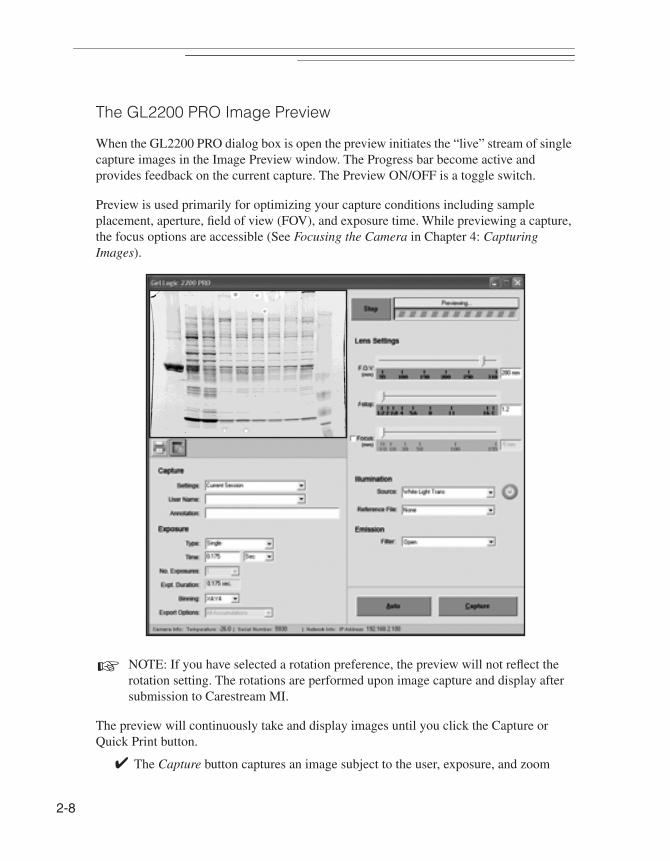
The GL2200 PRO Image Preview
When the GL2200 PRO dialog box is open the preview initiates the “live” stream of single capture images in the Image Preview window. The Progress bar become active and provides feedback on the current capture. The Preview ON/OFF is a toggle switch.
Preview is used primarily for optimizing your capture conditions including sample placement, aperture, field of view (FOV), and exposure time. While previewing a capture, the focus options are accessible (See Focusing the Camera in Chapter 4: Capturing Images).
☞ NOTE: If you have selected a rotation preference, the preview will not reflect the rotation setting. The rotations are performed upon image capture and display after submission to Carestream MI.
The preview will continuously take and display images until you click the Capture or Quick Print button.
✔ The Capture button captures an image subject to the user, exposure, and zoom

System
Overview
2
settings. The image opens as a new Carestream MI project.
✔ The Quick Print button sends the captured image directly to the default printer without saving to disk.
Capture Section of the GL2200 PRO Acquire Window
The Capture section of the GL2200 PRO window contains the Settings, User Name, and Annotation options. Let’s review each option:
Settings
You can speed up the capture process by creating custom capture settings for the various types of experiments or for specific personal preferences. Once saved, these settings can be conveniently applied to future image captures.
You can make modifications to the settings (i.e., change exposure time) or delete a setting using the Update Settings or Delete Settings option, respectively. The Settings pop-up menu also contains a number of factory-defined settings useful for common laboratory imaging applications.
Saved settings include:
✔ Type
✔ Exposure time
✔ Number of exposures
✔ Illumination correction
✔ Image orientation
2-9
2-10
✔ Preferences selections
✔ Saturation levels
☞ NOTE: The Settings option does not save the user name or annotations.
☞ NOTE: Custom settings are saved as individual files in C:\Program Files\Molecular Imaging\ MI\Application\GL2200\GL2200_Settings (Windows) or in the Molecular Imaging\MI\Application\MI Extensions\GL2200_Settings (Macintosh) subfolders.
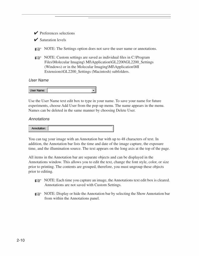
User Name
Use the User Name text edit box to type in your name. To save your name for future experiments, choose Add User from the pop-up menu. The name appears in the menu. Names can be deleted in the same manner by choosing Delete User.
Annotations
You can tag your image with an Annotation bar with up to 48 characters of text. In addition, the Annotation bar lists the time and date of the image capture, the exposure time, and the illumination source. The text appears on the long axis at the top of the page.
All items in the Annotation bar are separate objects and can be displayed in the Annotations window. This allows you to edit the text, change the font style, color, or size prior to printing. The contents are grouped, therefore, you must ungroup these objects prior to editing.
☞ NOTE: Each time you capture an image, the Annotations text edit box is cleared. Annotations are not saved with Custom Settings.
☞ NOTE: Display or hide the Annotation bar by selecting the Show Annotation bar from within the Annotations panel.
1
System
Overview
2
2-1
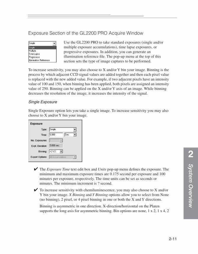
Exposure Section of the GL2200 PRO Acquire Window
Use the GL2200 PRO to take standard exposures (single and/or multiple exposure accumulations), time lapse exposures, or progressive exposures. In addition, you can generate an illumination reference file. The pop-up menu at the top of this section sets the type of image captures to be performed.
To increase sensitivity, you may also choose to X and/or Y bin your image. Binning is the process by which adjacent CCD signal values are added together and then each pixel value is replaced with the new added value. For example, if two adjacent pixels have an intensity value of 100 and 150, when binning has been applied, both pixels are assigned an intensity value of 250. Binning can be applied on the X and/or Y axis of an image. While binning decreases the resolution of the image, it increases the intensity of the signal.
Single Exposure
Single Exposure option lets you take a single image. To increase sensitivity you may also choose to X and/or Y bin your image.
✔ The Exposure Time text edit box and Units pop-up menu defines the exposure. The minimum and maximum exposure times are 0.175 second per exposure and 100 minutes per exposure, respectively. The time units can be set as seconds or minutes. The minimum increment is ? second.
✔ To increase sensitivity with chemiluminescence, you may also choose to X and/or Y bin your image. X Binning and Y Binning options allow you to select from None (no binning), 2 pixel, or 4 pixel binning in one or both the X and Y directions.
Binning is asymmetric in one direction. X-direction/horizontal on the Platen supports the long axis for asymmetric binning. Bin options are none, 1 x 2, 1 x 4, 2
2-12
x 2, 2 x 4, and 4 x 4.
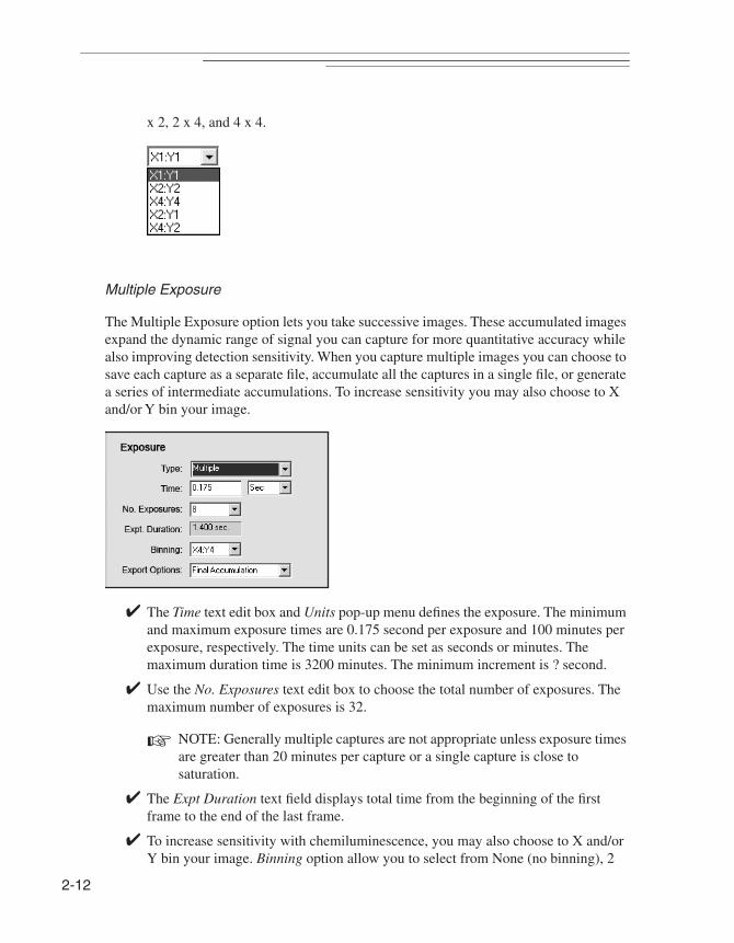
Multiple Exposure
The Multiple Exposure option lets you take successive images. These accumulated images expand the dynamic range of signal you can capture for more quantitative accuracy while also improving detection sensitivity. When you capture multiple images you can choose to save each capture as a separate file, accumulate all the captures in a single file, or generate a series of intermediate accumulations. To increase sensitivity you may also choose to X and/or Y bin your image.
✔ The Time text edit box and Units pop-up menu defines the exposure. The minimum and maximum exposure times are 0.175 second per exposure and 100 minutes per exposure, respectively. The time units can be set as seconds or minutes. The maximum duration time is 3200 minutes. The minimum increment is ? second.
✔ Use the No. Exposures text edit box to choose the total number of exposures. The maximum number of exposures is 32.
☞ NOTE: Generally multiple captures are not appropriate unless exposure times are greater than 20 minutes per capture or a single capture is close to saturation.
✔ The Expt Duration text field displays total time from the beginning of the first frame to the end of the last frame.
✔ To increase sensitivity with chemiluminescence, you may also choose to X and/or Y bin your image. Binning option allow you to select from None (no binning), 2

System
Overview
2
pixel, or 4 pixel binning in one or both the X and Y directions.
Binning is asymmetric in one direction. X-direction/horizontal on the Platen supports the long axis for asymmetric binning. Bin options are none, 1 x 2, 1 x 4, 2 x 2, 2 x 4, and 4 x 4.
2-13
2-14
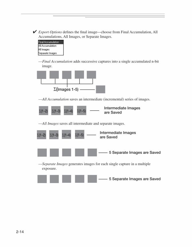
✔ Export Options defines the final image—choose from Final Accumulation, All Accumulations, All Images, or Separate Images.
—Final Accumulation adds successive captures into a single accumulated n-bit image.
—All Accumulation saves an intermediate (incremental) series of images.
—All Images saves all intermediate and separate images.
—Separate Images generates images for each single capture in a multiple exposure.
Σ(Images 1-5)
Intermediate Images Σ(1-2) Σ(1-3) Σ(1-4) Σ(1-5) are Saved
Intermediate ImagesΣ(1-2) Σ(1-3) Σ(1-4) Σ(1-5) are Saved
5 Separate Images are Saved
5 Separate Images are Saved

System
Overview
2
Time Lapse Exposure
The Time Lapse Exposure option is designed to take multiple exposures over fixed time intervals. For example, you may take a 10 second exposure every hour over the next 10 hours.
✔ The Time text edit box and Units pop-up menu defines the exposure. The minimum and maximum exposure times are 0.175 second per frame and 100 minutes per frame, respectively. The time units can be set as seconds or minutes. The maximum duration time is 3200 minutes. The minimal increment is ? second.
✔ The Interval is the time interval between the beginning of one exposure and the beginning of the next exposure. The minimum and maximum intervals are 5 second and 200 hours, respectively.
☞ NOTE: An interval must be at least 1 second greater than an exposure time.
✔ Stop After determines when to stop time lapse captures. You can set stop criteria based on experimental duration or by the number of frames. The maximum duration time is 3200 minutes. The maximum number of image frames that may be captured is ?.
✔ To increase sensitivity with chemiluminescence, you may also choose to X and/or Y bin your image. X Binning and Y Binning options allow you to select from None (no binning), 2 pixel, or 4 pixel binning in one or both the X and Y directions.
Binning is asymmetric in one direction. X-direction/horizontal on the Platen supports the long axis for asymmetric binning. Bin options are none, 1 x 2, 1 x 4, 2 x 2, 2 x 4, and 4 x 4.
2-15

2-16
Progressive Exposure
The Progressive Exposure option is designed to take a continuous sequence of exposures at different exposure times. You can automate complex exposure options—rather than manually having to set each exposure time. For example, you may want to capture an image at each of the following exposure times: 10, 20, 40, and 80 seconds.
✔ The Time text edit box and Units pop-up menu defines the exposure. The minimum and maximum exposure times are 0.175 second per frame and 100 minutes per frame, respectively. The time units can be set as seconds or minutes. The minimal increment is ? second.
✔ The Increment determines each new exposure time. The smallest increment for exposures is ? second. For example, if you set 60 second increments—each subsequent exposure is 60 seconds longer than the previous exposure. Another example would be to set an increment of 2X (Multiplier #X): If the first exposure was 1 minute, each successive exposure is double the previous exposure (2, 4, 8, 16 minutes, etc.). In addition, you can input the geometric order for generating exposure times. In this case the number entered is the power to which successive exposure times is raised.
✔ Use the No. Exposures text edit box to choose the total number of exposures. The maximum number of exposures is 32.
✔ To increase sensitivity with chemiluminescence, you may also choose to X and/or Y bin your image. X Binning and Y Binning options allow you to select from None (no binning), 2 pixel, or 4 pixel binning in one or both the X and Y directions.
Binning is asymmetric in one direction. X-direction/horizontal on the Platen supports the long axis for asymmetric binning. Bin options are none, 1 x 2, 1 x 4, 2 x 2, 2 x 4, and 4 x 4.

System
Overview
2
Illumination Reference
When a light source (UV or ambient light) is used, an illumination reference can be used to improve the quality of your data. The nonuniformity in the illumination generated by the UV bulbs or ambient white light is highly reproducible and may be corrected by simply normalizing the image by an illumination reference image. The f-stop and field of view settings used to capture the image must be the same as those used to generate the illumination reference file. See Generating an Illumination Reference File Library in Chapter 4: Capturing Images.
✔ The Exposure Time defines the exposure. The minimum and maximum exposure times are 0.175 second per exposure and 100 minutes per exposure, respectively. The time units can be set as seconds or minutes. The minimum increment is 0.1 second.
Lens Section of the GL2200 PRO Acquire Window
The GL2200 PRO camera lens is computer controlled.
The Field of View (F.O.V) buttons adjusts the field of view setting of the lens.
The f-stop buttons regulates the amount of light reaching the sensor for an exposure.
The Focus buttons adjusts the focus of the lens. The Focus checkbox accesses the software-assisted focusing aid that is described in Focusing the Camera in Chapter 4: Capturing Images.
2-17
2-18
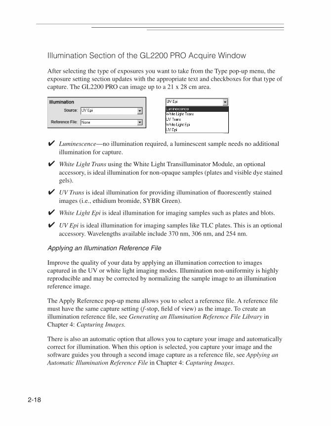
Illumination Section of the GL2200 PRO Acquire Window
After selecting the type of exposures you want to take from the Type pop-up menu, the exposure setting section updates with the appropriate text and checkboxes for that type of capture. The GL2200 PRO can image up to a 21 x 28 cm area.
✔ Luminescence—no illumination required, a luminescent sample needs no additional illumination for capture.
✔ White Light Trans using the White Light Transilluminator Module, an optional accessory, is ideal illumination for non-opaque samples (plates and visible dye stained gels).
✔ UV Trans is ideal illumination for providing illumination of fluorescently stained images (i.e., ethidium bromide, SYBR Green).
✔ White Light Epi is ideal illumination for imaging samples such as plates and blots.
✔ UV Epi is ideal illumination for imaging samples like TLC plates. This is an optional accessory. Wavelengths available include 370 nm, 306 nm, and 254 nm.
Applying an Illumination Reference File
Improve the quality of your data by applying an illumination correction to images captured in the UV or white light imaging modes. Illumination non-uniformity is highly reproducible and may be corrected by normalizing the sample image to an illumination reference image.
The Apply Reference pop-up menu allows you to select a reference file. A reference file must have the same capture setting (f-stop, field of view) as the image. To create an illumination reference file, see Generating an Illumination Reference File Library in Chapter 4: Capturing Images.
There is also an automatic option that allows you to capture your image and automatically correct for illumination. When this option is selected, you capture your image and the software guides you through a second image capture as a reference file, see Applying an Automatic Illumination Reference File in Chapter 4: Capturing Images.

System
Overview
2
Emission Filter Section of the GL2200 PRO Acquire Window
Selecting a filter may optimize the fluorescent signal by discriminating against background and/or differentiating between multiple fluorochromes within the experimental sample.
The Filter pop-up menu selects the emission filter used during capture.
The system includes a 590 nm band pass filter. The 590 nm filter is specially designed to eliminate light other than 590 nm wavelength produced by ethidium bromide (or other similar emission wavelength) stained samples. It permits maximum sample detection sensitivity by minimizing background. Additional filters including 440 nm, 535 nm, 570 nm and 670 nm are available from Carestream Molecular Imaging or your Carestream Molecular Imaging dealer (See Appendix A: Parts and Accessories).
Buttons on the GL2200 PRO Acquire Window
The buttons on the GL2200 PRO Acquire window execute functions. Let’s review.
The Preview/Stop button initiates the Preview mode. When the Preview is running the button toggles to the Stop button.
The Capture button initiates image acquisition. Once acquired, files can be analyzed, annotated, and printed.
The Quick Print button sends the image directly to your printer and no copy of the image is saved.
The Preferences button opens the GL2200 PRO Preferences window and is where you can customize certain capture parameters. The GL2200 PRO Preferences window is described in more detail later in this chapter.
2-19
2-20
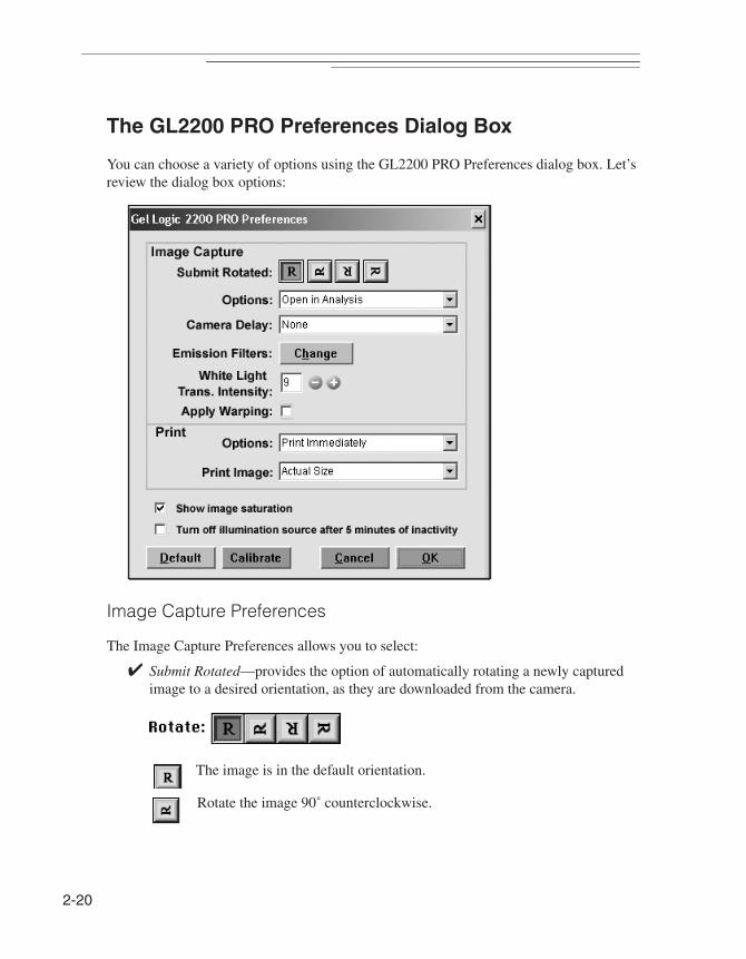
The GL2200 PRO Preferences Dialog Box
You can choose a variety of options using the GL2200 PRO Preferences dialog box. Let’s review the dialog box options:
Image Capture Preferences
The Image Capture Preferences allows you to select:
✔ Submit Rotated—provides the option of automatically rotating a newly captured image to a desired orientation, as they are downloaded from the camera.
The image is in the default orientation.
Rotate the image 90˚ counterclockwise.
System
Overview
2
Rotate the image 180˚.
Rotate the image 90˚ clockwise.
☞ NOTE: The Rotation buttons do not change the orientation of the preview image. The rotation occurs during submission of the image to Carestream MI.
☞ NOTE: Rotation events are documented in the History tab of the Lane Information window since rotations are destructive to the original data file.
✔ Options—You can choose to open images after capture in either Carestream MI Analysis panel or Annotations panel.
✔ Camera Delay—configures the GL2200 PRO camera to take a picture with 5 or 10 second delay. This delay occurs after the capture command is executed and before the actual picture is taken. Choose the time in the Camera Delay pop-up menu.
☞ NOTE: This option is useful in situations when light tables take several seconds to become completely illuminated.
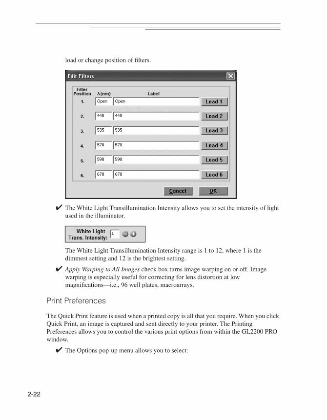
✔ Emission Filters Change button access the Edit Filters dialog box where you can
2-21
2-22
load or change position of filters.
✔ The White Light Transillumination Intensity allows you to set the intensity of light used in the illuminator.
The White Light Transillumination Intensity range is 1 to 12, where 1 is the dimmest setting and 12 is the brightest setting.
✔ Apply Warping to All Images check box turns image warping on or off. Image warping is especially useful for correcting for lens distortion at low magnifications—i.e., 96 well plates, macroarrays.
Print Preferences
The Quick Print feature is used when a printed copy is all that you require. When you click Quick Print, an image is captured and sent directly to your printer. The Printing Preferences allows you to control the various print options from within the GL2200 PRO window.
✔ The Options pop-up menu allows you to select:
System
Overview
2
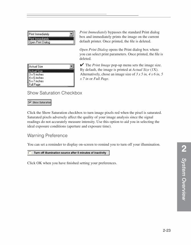
Print Immediately bypasses the standard Print dialog box and immediately prints the image on the current default printer. Once printed, the file is deleted.
Open Print Dialog opens the Print dialog box where you can select print parameters. Once printed, the file is deleted.
✔ The Print Image pop-up menu sets the image size. By default, the image is printed at Actual Size (1X). Alternatively, chose an image size of 3 x 5 in, 4 x 6 in, 5 x 7 in or Full Page.
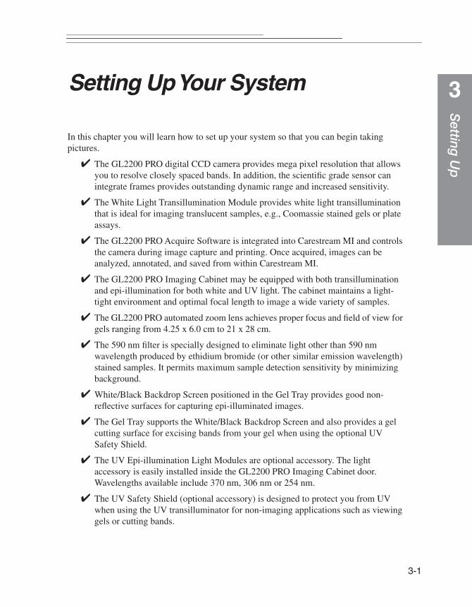
Show Saturation Checkbox
Click the Show Saturation checkbox to turn image pixels red when the pixel is saturated. Saturated pixels adversely affect the quality of your image analysis since the signal readings do not accurately measure intensity. Use this option to aid you in selecting the ideal exposure conditions (aperture and exposure time).
Warning Preference
You can set a reminder to display on-screen to remind you to turn off your illumination.
Click OK when you have finished setting your preferences.
2-23

2-24
Setting
Up
3
Setting Up Your SystemIn this chapter you will learn how to set up your system so that you can begin taking pictures.
✔ The GL2200 PRO digital CCD camera provides mega pixel resolution that allows you to resolve closely spaced bands. In addition, the scientific grade sensor can integrate frames provides outstanding dynamic range and increased sensitivity.
✔ The White Light Transillumination Module provides white light transillumination that is ideal for imaging translucent samples, e.g., Coomassie stained gels or plate assays.
✔ The GL2200 PRO Acquire Software is integrated into Carestream MI and controls the camera during image capture and printing. Once acquired, images can be analyzed, annotated, and saved from within Carestream MI.
✔ The GL2200 PRO Imaging Cabinet may be equipped with both transillumination and epi-illumination for both white and UV light. The cabinet maintains a light- tight environment and optimal focal length to image a wide variety of samples.
✔ The GL2200 PRO automated zoom lens achieves proper focus and field of view for gels ranging from 4.25 x 6.0 cm to 21 x 28 cm.
✔ The 590 nm filter is specially designed to eliminate light other than 590 nm wavelength produced by ethidium bromide (or other similar emission wavelength) stained samples. It permits maximum sample detection sensitivity by minimizing background.
✔ White/Black Backdrop Screen positioned in the Gel Tray provides good non-reflective surfaces for capturing epi-illuminated images.
✔ The Gel Tray supports the White/Black Backdrop Screen and also provides a gel cutting surface for excising bands from your gel when using the optional UV Safety Shield.
✔ The UV Epi-illumination Light Modules are optional accessory. The light accessory is easily installed inside the GL2200 PRO Imaging Cabinet door. Wavelengths available include 370 nm, 306 nm or 254 nm.
✔ The UV Safety Shield (optional accessory) is designed to protect you from UV when using the UV transilluminator for non-imaging applications such as viewing gels or cutting bands.
3-1

3-2
Environmental Requirements
The GL2200 PRO is designed to operate effectively within the temperature and humidity ranges typically found in laboratories. For effective operation, the temperature and relative humidity should be:
✔ Temperature: 18° to 28° C
✔ Relative Humidity: < 75%, non-condensing
✔ Altitude: This product is designed for use at altitudes up to 2000 meters.
This product is designed for indoor use only. This product meets Pollution Degree 2 standards in accordance with IEC 664.
Electrical Requirements✔ 120-240 VAC- 50/60Hz*, 2A
* Supply voltage fluctuations should not to exceed ± 10%.
This product is designed to withstand transient over voltage according to Installation Category II.
Refer to your computer operators's manual for its electrical requirements.
Space Requirements
The GL2200 PRO overall weight and dimensions are as follows:
✔ 54.6 cm (21.5 inches) length and 42 cm (16.5) deep and 62.6 cm (24.6 inches) high
✔ 57.1 kg (125.6 pounds)
We recommend that the instrument and computer be placed on a bench or table that is level and capable of supporting 68 kg(150 pounds), located not more than 3 feet (91 cm) from an electrical outlet.
The GL2200 PRO, including computer CPU, monitor and keyboard, requires a minimum space 48 inches wide, 20 inches deep and 35 inches high (122 cm x 51 cm x 69 cm). These dimensions do not allow for a printer or other peripheral device.
Additional space adjacent to, above or behind the GL2200 PRO will allow for easier operation.

Setting
Up
3
Installing the Carestream Molecular Imaging Software—WindowsAny prior versions of MI, 1D and/or camera software that are loaded on the computer must be uninstalled prior to installation. If you are a new user, proceed to Carestream Molecular Imaging Software Installation—Windows. Software installations on Windows-based computers may require administrator privileges.
If you have purchased the Carestream Molecular Imaging Software Network Edition (Carestream MI NE) to use with your GL2200 PRO:
✔ Follow the instructions in the Carestream Molecular Imaging Software Network Edition Administrator’s Manual to install Carestream MI NE Software.
✔ Then proceed to Launching Carestream Molecular Imaging Software for the First Time, later in this chapter.
If you have purchased the Carestream Molecular Imaging Software, Regulatory Edition with Network Licensing (Carestream MI RE) to use with your Gel Logic 2200 PRO Imaging System:
✔ Follow the instructions in the Carestream Molecular Imaging Software, Regulatory Edition Network Administrator’s Manual to install Carestream MI RE Software.
✔ Then proceed to proceed to Launching Molecular Imaging Software for the First Time, later in this chapter.
Uninstalling a Previous Version MI or 1D Software—Windows
1 Remove your MI or 1D copy protection device from your computer.
2 Inactivate any virus protection software.
☞ NOTE: Norton Utilities and Norton Antivirus software must be deactivated before you uninstall the software. The software might not uninstall properly with the virus protection left running. After installation, you can restart your virus protection software.
3 Close all software applications that may be running on your computer.
☞ NOTE: Cameras should not be connected to the computer while uninstalling the software.
3-3

3-4
4 Move any customized standards or templates and any projects from their respective subfolders in your existing MI or1D X.X folder to a temporary folder outside the MI or 1D folder. If you are currently using the MI database, also move the database folder.
5 Uninstall previous version(s) of MI or 1D Software.
✔ Windows XP—Unstall MI by choosing Control Panel from the Start menu and Add/Remove Programs. Scroll to locate MI X.X. Click to select. Click the Add/Remove button and follow the on-screen instructions to uninstall. You can also uninstall the application using your MI CD. The installer shield automatically detects that you have the software loaded and offers an uninstall option. A window informs you as each software has successfully been removed. Uninstall 1D by choosing Programs from the Start menu and selecting Remove 1D X.X from the 1D X.X submenu. Uninstall MI NE, MI RE or 1D NE following the instructions provided in your Network Administrator’s Manual.
✔ Windows Vista—Uninstall MI by choosing Control Panel from the Start menu and Uninstall a Program from the Program menu. Scroll to locate MI X.X. Click to select. Click Uninstall/Change and follow the on-screen instructions to uninstall. You can also uninstall the application using your MI CD. The installer shield automatically detects that you have the software loaded and offers an uninstall option. A window informs you as each software has successfully been removed. Uninstall 1D by choosing Programs from the Start menu and selecting Remove 1D X.X from the 1D X.X submenu. Uninstall MI NE, MI RE or 1D NE following the instructions provided in your Network Administrator’s Manual.
✔ Windows 7—Uninstall MI by choosing Control Panel from the Start menu and Uninstall a Program from the Program menu. Scroll to locate MI X.X. Click to select. Click Uninstall/Change and follow the on-screen instructions to uninstall. You can also uninstall the application using your MI CD. The installer shield automatically detects that you have the software loaded and offers an uninstall option. A window informs you as each software has successfully been removed. Uninstall MI NE or MI RE following the instructions provided in your Network Administrator’s Manual.
6 Uninstall additional software.
✔ Windows XP—Choose Control Panel from the Start menu and Add/Remove Programs. Scroll to locate Sentinel System Driver. Click to select. Click the Add/Remove button and follow the on-screen instructions to uninstall. A window informs you as each software has successfully been removed.
✔ Windows Vista—Choose Control Panel from the Start menu and Uninstall a Program from the Program menu. Scroll to locate Sentinel System Driver. Click to select. Click Uninstall/Change and the on-screen instructions to uninstall. A window informs you as each software has successfully been removed.

Setting
Up
3
✔ Windows 7—Choose Control Panel from the Start menu and Uninstall a Programfrom the Program menu. Scroll to locate Sentinel System Driver. Click to select. Click Uninstall/Change and the on-screen instructions to uninstall. A window informs you as each software has successfully been removed.
☞ NOTE: Automated uninstall features on some systems may not remove all previous program elements. Check drives for residual folders and files. Manual deletion of these folders and files may be necessary.
7 Restart your computer.
8 Proceed to Carestream Molecular Imaging Software Installation—Windows.
3-5

3-6
Carestream Molecular Imaging Software Installation—Windows
Carestream Molecular Imaging Software is installed like most Windows application programs and requires administrator privileges.
1 Inactivate any virus protection software.
☞ NOTE: Norton Utilities and Norton Antivirus software must be deactivated before you install the software. The installation might not run properly with the virus protection left running. After installation, you can restart your virus protection software.
2 Close all software applications that may be running on your computer.
☞ NOTE: Cameras should not be connected to the computer while installing the software.
☞ NOTE: Remove any copy protection devices attached to your computer during installation.
3 Insert the Carestream Molecular Imaging Software Version 5.X CD into your CD drive and double-click on the Carestream MI SE Installer.exe icon to launch the installer.
☞ NOTE: Windows Vista and Windows 7 users: A User Account Control window will appear. Click Yes to confirm installation of Carestream MI SE software.
4 The installer leads you through the installation process. Make sure to install the software in the default directory to ensure full functionality of the system.
☞ NOTE: The Select Components window allows you to install Carestream MI with or without the database. The image database should only be installed in the location that you want to maintain images. Unclick the Image Dababase checkbox only if you intend to store your images on another networked machine.
☞ NOTE: Windows 7 users: A Windows warning window appears asking if you want to allow Unpublished Driver Software to be installed. Click to allow installation of the driver.
5 While the software installation is occurring, complete your Carestream MI Software Registration Card and return the card by mail. This ensures that you receive information on new software releases, periodic maintenance releases, and technical bulletins.
6 A dialog box appears when the installation is complete. Select the option to restart the computer and click Finish.
7 Proceed to Copy Protection Device Installation—Windows.
Setting
Up
3
Copy Protection Device Installation—WindowsCarestream MI is copy protected using a device that plugs into the USB port of your computer. It will not launch unless this device is attached to your computer. If you are installing the system for the first time, locate and install the copy protection device according to the instructions below. If you are upgrading your system, your package may or may not contain a new copy protection device.
To install the copy protection device:
1 Plug the copy protection device into a USB port of your computer. Please make sure that the connection is secure.
☞ NOTE: Windows XP Users: A Welcome to the Found New Found Hardware Wizard dialog box appears on screen. You will be asked if you want the Windows update to search for software. Click No not at this time and advance through the installation wizard.
☞ NOTE: Windows Vista and Windows 7 Users: Installing Device Driver Software dialog box will appear in the lower right hand corner. Upon completing installation, a message appears informing you that Rainbow USB Superpro Device Driver Software installed successfully.
☞ NOTE: If you are upgrading from a previous version of the MI or 1D Software and received a new copy protection device, you must attach both the old and new copy protection devices to your computer. After you launch the newest version for the first time, your old copy protection device is be deactivated. Remove and discard the old key.
☞ NOTE: If your computer has multiple USB ports, you can plug the copy protection device into any of them. The software, when launched, checks all available USB ports.
2 Proceed to Gel Logic 2200 Camera Files Installation—Windows.
3-7
3-8
Gel Logic 2200 Camera Files Installation—Windows
1 Inactivate any virus protection software.
☞ NOTE: Norton Utilities and Norton Antivirus Software must be deactivated before you install the Carestream Software. The installation might not run properly with the virus protection left active. After installation, you can restart your virus protection software.
2 Insert the Carestream GL 2200 Camera Files CD into your CD drive and double-click the Gel Logic 2200 Support Setup.exe icon to launch the Windows installer application.
☞ NOTE: Carestream MI Software must be installed prior to the camera files installation.
3 The installer proceeds and display a dialog box when installation is complete.
4 Verify that the appropriate GL2200PRO_HPMS and GL2200PRO_DCRS files have been installed in the proper location. Navigate to C:\Program Files\Molecular Imaging MI\MI Application\GL2200.
5 Your installation is complete, proceed to Windows Power Settings, later in this chapter.

Setting
Up
3
Windows Power SettingsThe GL2200 PRO requires that your computer Energy Saver features be disabled. This process by may differ depending upon the Windows software installed.
Windows XP
1 Click the Power Options icon from the Start menu and the Control Panel submenu.
2 Click Power Schemes tab and select Always On from the Power Schemes pop-up menu.
3 The settings for Turn off monitor, Turn off hard disks, System standby and System hibernates functions become Never.
4 Click OK and proceed to Launching Carestream Molecular Imaging Software for the First Time.
Windows Vista
1 Select System and Maintenance from the Start menu and the Control Panel.
2 Click Power Options, select to Create a power plan and choose High Performance from the list of protocols. Click Next and then Create
3 Proceed to Launching Carestream Molecular Imaging Software for the First Time.
Windows 7
1 Click System and Security from Start menu and the Control Panel submenu.
2 Click Power Options, select to Create a power plan and choose High Performance from the list of protocols. Click Next and then Create
3 Proceed to Launching Carestream Molecular Imaging Software for the First Time.
3-9

3-10
Installing the Carestream Molecular Imaging Software—Macintosh
Any prior versions of MI, 1D or camera software that are loaded on the computer must be uninstalled prior to installation. If you are a new user, proceed to Carestream Molecular Imaging Software Installation—Macintosh. Macintosh OS X installations may require authentication of permissions.
If you have purchased the Carestream Molecular Imaging Software Network Edition (Carestream MI NE) to use with your Carestream Gel Logic 2200 PRO Imaging System:
✔ Follow the instructions in the Carestream Molecular Imaging Software Network Edition Administrator’s Manual to install Carestream MI NE Software.
✔ Then proceed to Launching Carestream Molecular Imaging Software for the First Time, later in this chapter.
If you have purchased the Carestream Molecular Imaging Software, Regulatory Edition with Network Licensing (Carestream MI RE) to use with your GL2200 PRO:
✔ Follow the instructions in the Carestream Molecular Imaging Software, Regulatory Edition Network Administrator’s Manual to install Carestream MI RE Software.
✔ Then proceed to Launching Carestream Molecular Imaging Software for the First Time, later in this chapter.
Setting
Up
3
Uninstalling a Previous Version of MI or 1D Software—Macintosh1 Remove your MI or 1D copy protection device from your computer.
2 Inactivate any virus protection software.
☞ NOTE: Norton Utilities and Norton Antivirus software must be deactivated before you uninstall the software. The software might not uninstall properly with the virus protection left running. After installation, you can restart your virus protection software.
3 Close all software applications that may be running on your computer.
☞ NOTE: Cameras should not be connected to the computer while uninstalling the software.
4 Move any customized standards or templates and any projects from their respective subfolders in your existing MI X.X or 1D X.X folder to a temporary folder outside the folder. If you are currently using the MI database, also move the database folder. Click the Applications folder and locate the database folder labeled GMPDB located in the MI folder and the KodakAdminPortal subfolder.
5 Place the MI X.X or 1D X.X folder in the Trash.
☞ NOTE: If uninstalling MI version 4.5 or greater, double-click the uninstall application in the Applications folder and the MI subfolder. Follow the on- screen instructions to uninstall MI.
6 Restart your computer.
7 Empty the Trash.
8 Proceed to Carestream Molecular Imaging Software Installation—Macintosh.
3-11
3-12
Carestream Molecular Imaging Software Installation—Macintosh
1 Inactivate any virus protection software.
☞ NOTE: Norton Utilities and Norton Antivirus software must be deactivated before you install the software. The installation might not run properly with the virus protection left running. After installation, you can restart your virus protection software.
2 Close all software applications that might be running on your computer.
☞ NOTE: Cameras should not be connected to the computer while installing the software.
☞ NOTE: Remove any copy protection devices attached to your computer during installation.
3 Insert the Carestream Molecular Imaging Software Version 5.X CD into your CD drive and double-click the Carestream MI SE Installer.mpkg icon to launch the installer application.
4 The installer leads you through the installation process. Make sure to select the Easy Install to install the software in the default directory and ensure full functionality of the system.
☞ NOTE: The Select Components window allows you to install MI without the database. Only install the database in the location that you want to maintain images acquired from the system.
5 While the software installation is occurring, complete your Carestream MI Software Registration Card and return the card by mail. This process takes only a few minutes to complete and ensures that you receive information regarding new software releases, periodic maintenance releases, and technical bulletins.
6 The installer notifies you when the installation is complete. Click Restart.
7 Proceed to Copy Protection Device Installation—Macintosh.
Setting
Up
3
Copy Protection Device Installation—MacintoshCarestream Molecular Imaging Software is copy protected using a device that plugs into the USB port of your computer. Carestream MI will not launch unless this device is attached to your computer. If you are installing the system for the first time, locate and install the copy protection device according to the instructions below. If you are upgrading your system, your package may or may not contain a new copy protection device.
To install the copy protection device:
1 Plug the copy protection device into a USB port of your computer. Please make sure that the connection is secure.
☞ NOTE: If you are upgrading from a previous version of the MI or 1D Software and received a new copy protection device, you must attach both the old and new copy protection devices to your computer. After you launch the newest version for the first time, your old copy protection device is deactivated. Remove and discard the old key.
2 Proceed to Gel Logic 2200 PRO Camera File Installation—Macintosh.
3-13

3-14
Gel Logic 2200 Camera File Installation—Macintosh
1 Inactivate any virus protection software.
☞ NOTE: Norton Utilities and Norton Antivirus Software must be deactivated before you install the KODAK software. The installation might not run properly with the virus protection left active. After installation, you can restart your virus protection software.
2 Insert the KODAK GL 2200 Camera Files CD into your CD drive and double-click the Camera Files Installer to launch the installer application.
☞ NOTE: KODAK MI Software must be installed prior to the camera files installation.
☞ NOTE: In a manual copy operation, the HPMS and DCRS folders must have their Ownership & Permissions reset in OS X to allow access by other user accounts. After copying, select the folders one at a time and click Get Info from the File menu. Set the Others pop-up menu in the Ownership & Permissions section to Read & Write. Click Apply.
3 The installer proceeds and display a dialog boxes when installation is complete.
4 Verify that the GL2200_HPMS and GL2200_DCRS files have been installed in the proper location Applications\KODAK MI\MI Extensions\GL2200.
5 Your installation is complete, proceed to Macintosh Power Settings.

Setting
Up
3
Macintosh Power SettingsThe GL2200 PRO requires that the Energy Saver settings on your computer be disabled.
To disable the system sleep features:
1 Choose Energy Saver from the File menu and the System Preferences submenu or from System Preferences on the Dock. The Energy Saver window opens.
2 Click the Sleep tab and set the Computer and Display sleep sliders to Never. Ensure the Put the hard disk(s) to sleep when possible checkbox is unchecked.
3 Proceed to Launching Carestream Molecular Imaging Software for the First Time.
3-15
3-16
Launching Carestream Molecular Imaging Software for the First Time
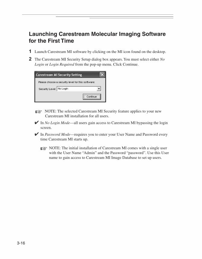
1 Launch Carestream MI software by clicking on the MI icon found on the desktop.
2 The Carestream MI Security Setup dialog box appears. You must select either No Login or Login Required from the pop-up menu. Click Continue.
☞ NOTE: The selected Carestream MI Security feature applies to your new Carestream MI installation for all users.
✔ In No Login Mode—all users gain access to Carestream MI bypassing the login screen.
✔ In Password Mode—requires you to enter your User Name and Password every time Carestream MI starts up.
☞ NOTE: The initial installation of Carestream MI comes with a single user with the User Name “Admin” and the Password “password”. Use this User name to gain access to Carestream MI Image Database to set up users.

Setting
Up
3
3 The Login window appears. Enter “Admin” as the Username and “password” as thePassword. The Host Name default value will cause Carestream MI to search your local drive for the Carestream MI database. If the Carestream MI database is located on another machine or file server, enter the IP address of that machine in the Host Name field. Click Login.
☞ NOTE: The initial installation of Carestream MI comes with a single user with the User Name “Admin” and the Password “password”. Use this User name to gain access to Carestream MI Image Database to set up users.
☞ NOTE: If no Carestream MI database is detected at the Host Name location, you will be asked if you would like to continue without connection to a database.
4 If you selected No Login in the Carestream MI Security Setup dialog box, future launches of Carestream MI will skip the login windows and open to a Carestream MI Project window. Proceed to Step 6 to enter your User Name, Company and Carestream MI Software serial number.
5 If you selected Login Required in the Carestream MI Security Setup dialog box, you will be prompted to contact database administrator. Click OK to open Carestream MI. Future launches of Carestream MI will require both Username and Password to gain access to Carestream MI and the Carestream MI database.
6 Type your Name and Organization in the boxes provided.
3-17

3-18
7 Enter your Serial Number exactly (including dashes) as provided on your registration card or serial number card included in your Carestream MI package.
☞ NOTE: The serial number is required when installing Carestream MI or when contacting Carestream Molecular Imaging Technical Support. Keep the serial number in a safe location.
8 Click OK. The Carestream MI Project window appears. Your installation is complete.
☞ NOTE: Previous MI or 1D users may move any customized standards or templates, any projects, and database folders back into the new MI folder.
☞ NOTE: If you selected Login Required in the Carestream MI Security Setup dialog box when Carestream MI was first launched, you can set up User Names and Passwords for each Carestream MI user. Proceed to Carestream MI Image Database, later in this chapter.
Setting
Up
3
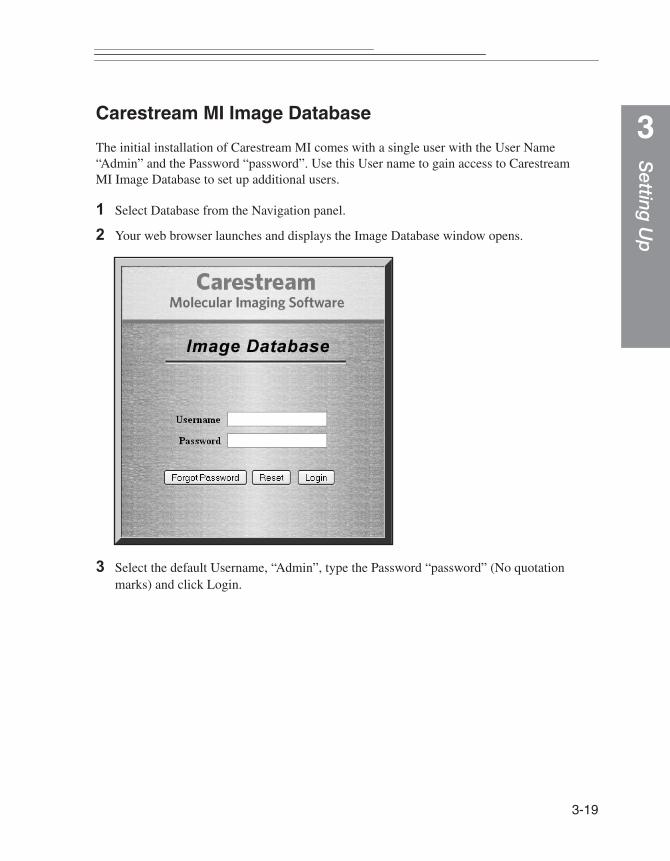
Carestream MI Image DatabaseThe initial installation of Carestream MI comes with a single user with the User Name “Admin” and the Password “password”. Use this User name to gain access to Carestream MI Image Database to set up additional users.
1 Select Database from the Navigation panel.
2 Your web browser launches and displays the Image Database window opens.
3 Select the default Username, “Admin”, type the Password “password” (No quotation marks) and click Login.
3-19

3-20
4 Click the Users tab to access the User Administration page, where you can add users. Select Add Users.
5 The User Information page appears. Fill out the information including First Name, Last Name, Username (enter a temporary password), Password, Job Function (Administrator, Principal Investigator, Research Scientist), an e-mail address. Click Create.
☞ NOTE: New users are automatically added to the default Investigation and default Study.
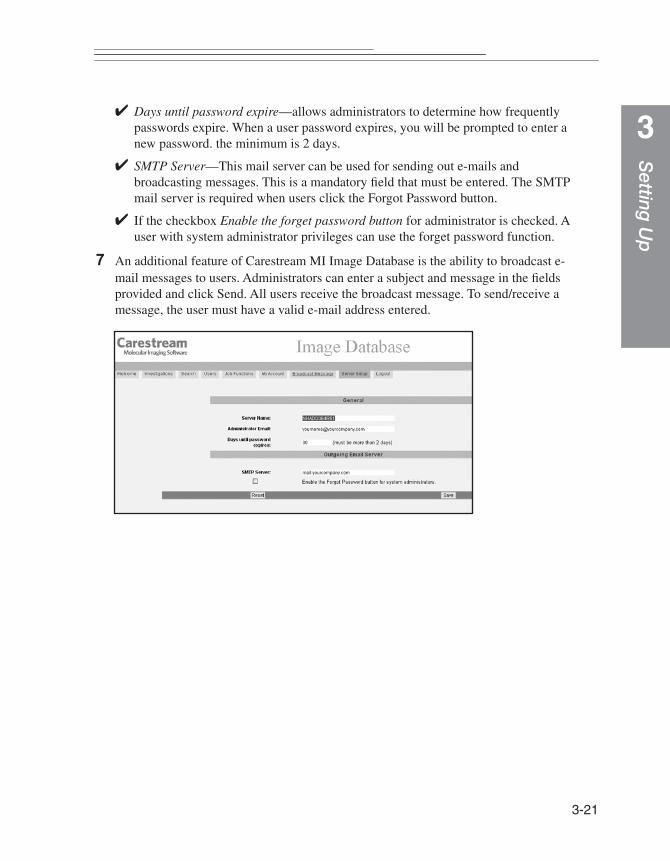
6 You may want to take some time to click on the Server Setup button to give your database server a name and specify a SMTP mail server.
✔ Server ID—is a unique name for your machine. The Server ID can either be a name or number.
✔ Administrator E-mail—this indicates the e-mail address of the Administrators.
Setting
Up
3
✔ Days until password expire—allows administrators to determine how frequentlypasswords expire. When a user password expires, you will be prompted to enter a new password. the minimum is 2 days.
✔ SMTP Server—This mail server can be used for sending out e-mails and broadcasting messages. This is a mandatory field that must be entered. The SMTP mail server is required when users click the Forgot Password button.
✔ If the checkbox Enable the forget password button for administrator is checked. A user with system administrator privileges can use the forget password function.
7 An additional feature of Carestream MI Image Database is the ability to broadcast e-mail messages to users. Administrators can enter a subject and message in the fields provided and click Send. All users receive the broadcast message. To send/receive a message, the user must have a valid e-mail address entered.
3-21
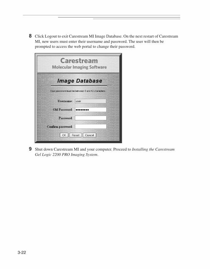
3-22
8 Click Logout to exit Carestream MI Image Database. On the next restart of Carestream MI, new users must enter their username and password. The user will then be prompted to access the web portal to change their password.
9 Shut down Carestream MI and your computer. Proceed to Installing the Carestream Gel Logic 2200 PRO Imaging System.
Setting
Up
3
Installing the Carestream Gel Logic 2200 PRO Imaging SystemThe GL2200 PRO has been designed to eliminate the need to take pictures in a darkroom. The set-up is designed to only take a few minutes. So let’s begin.
WARNING: Do not plug the Camera/Computer Ethernet Interface Cable or the Communication Cable into the computer unless Carestream Molecular Imaging Software has been installed. (See Installing the Carestream Molecular Imaging Software—Windows or Installing the Carestream Molecular Imaging Software—Macintosh, earlier in this chapter).
WARNING: The power cord is the primary disconnect device from the AC (MAINS) outlet. Do not connect the unit to the AC (MAINS) outlet until installation is complete.
Installing the GL2200 PRO Imaging Hardware
1 Remove the base GL2200 PRO Imaging Cabinet and GL2200 PRO Camera Module from the shipping container. Remove packing materials.
2 Verify components listed in Package Contents in Chapter 1: Introduction of this User’s Guide.
3 Position the base cabinet next to your computer.
4 Use the wrench provided to level the unit on your lab bench. Verify that the cabinet door clears the table.
5 Open the door of the GL2200 PRO Imaging Cabinet. Carefully set the GL2200 PRO Camera Module on top of the imaging cabinet.
WARNING:When mounting the camera module on top of the cabinet, we recommend that two people lift the camera module.
3-23
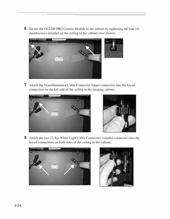
3-24
6 Secure the GL2200 PRO Camera Module to the cabinet by tightening the four (4) thumbscrews installed on the ceiling of the cabinet (two shown).
7 Attach the Transilluminator Cable Connector (larger connector) into the keyed connection on the left side of the ceiling in the imaging cabinet.
8 Attach the two (2) Epi White Light Cable Connectors (smaller connector) into the keyed connections on both sides of the ceiling in the cabinet.
FPO
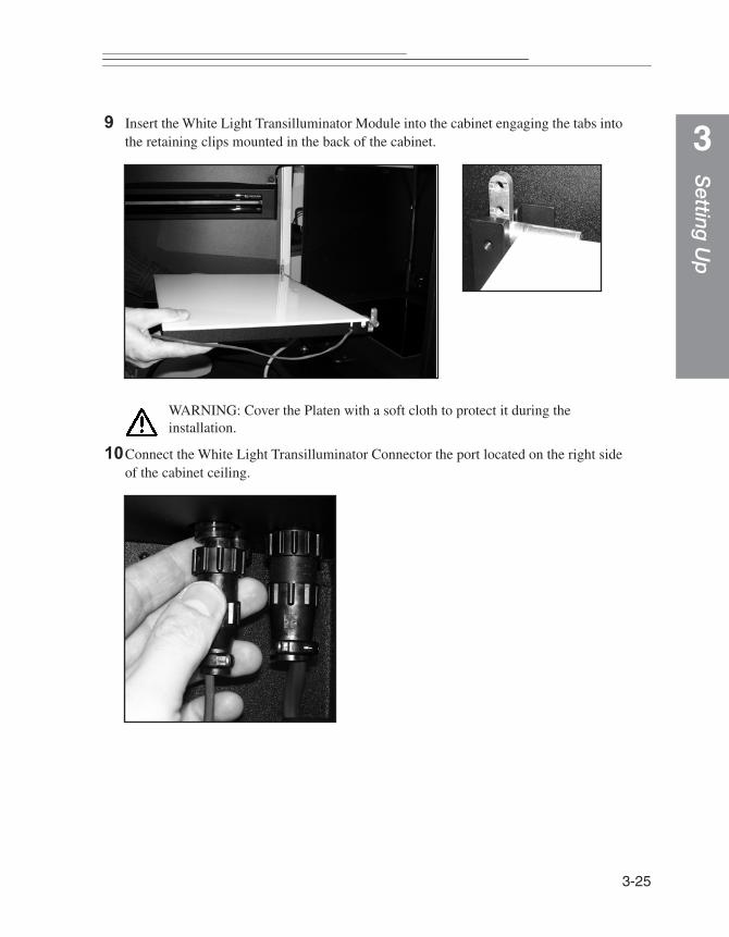
Setting
Up
3
9 Insert the White Light Transilluminator Module into the cabinet engaging the tabs intothe retaining clips mounted in the back of the cabinet.
WARNING: Cover the Platen with a soft cloth to protect it during the installation.
10Connect the White Light Transilluminator Connector the port located on the right side of the cabinet ceiling.
FPO
FPO
3-25
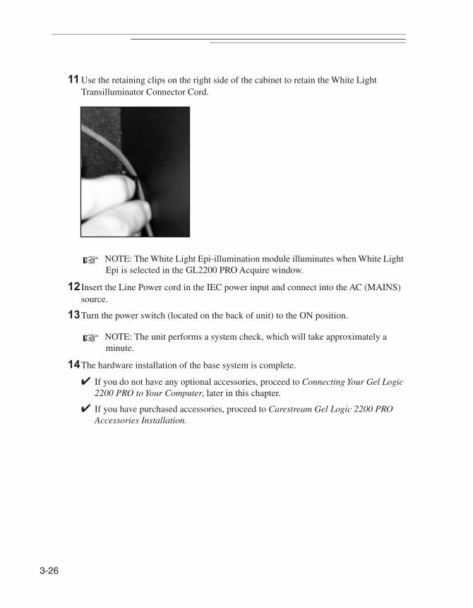
3-26
11 Use the retaining clips on the right side of the cabinet to retain the White Light Transilluminator Connector Cord.
☞ NOTE: The White Light Epi-illumination module illuminates when White Light Epi is selected in the GL2200 PRO Acquire window.
12 Insert the Line Power cord in the IEC power input and connect into the AC (MAINS) source.
13Turn the power switch (located on the back of unit) to the ON position.
☞ NOTE: The unit performs a system check, which will take approximately a minute.
14The hardware installation of the base system is complete.
✔ If you do not have any optional accessories, proceed to Connecting Your Gel Logic 2200 PRO to Your Computer, later in this chapter.
✔ If you have purchased accessories, proceed to Carestream Gel Logic 2200 PRO Accessories Installation.
Setting
Up
3
Carestream Gel Logic 2200 PRO Accessories InstallationAccessories are available for use with your Carestream Gel Logic 2200 PRO Imaging System to expand your system’s capabilities.
✔ The UV Epi-illumination Light Modules are optional accessory. The light accessory is easily installed inside the GL2200 PRO Imaging Cabinet door. Wavelengths available include 370 nm, 306 nm or 254 nm.
✔ The UV Safety Shield (optional accessory) is designed to protect you from UV when using the UV transilluminator for non-imaging applications such as viewing gels or cutting bands.
Installing the UV Epi-illumination Light Module (Optional Accessory)
The UV Epi-illumination Light Accessory is an optional accessory. The light accessory is easily installed inside the GL2200 PRO Imaging Cabinet door.
DANGER—Ultraviolet radiation emitted from this product. Avoid exposure. ALWAYS WEAR PROTECTIVE CLOTHING. EXPOSURE MAY CAUSE PREMATURE AGING OF THE SKIN AND CANCER. ALWAYS WEAR PROTECTIVE EYEWEAR; FAILURE TO DO SO MAY RESULT IN SEVERE BURNS OR LONG TERM INJURY TO EYE. Never look directly into the lamp. Exposure can cause eye and skin allergy and allergic reactions. Medications or cosmetics may increase your sensitivity to ultraviolet radiation. Consult physician before operating this product if you are using medications or have a history of skin problems or believe yourself especially sensitive to sunlight. For Laboratory Use Only.
WARNING: The UV source does not operate when the door is open. Do not attempt to override this feature.
1 Unpack the module and carefully examine it to determine that the glass filter is not broken. A slight rattling sound is normal caused by the movement of small particles in the fluorescent bulbs.
2 Open the cabinet door.
3-27
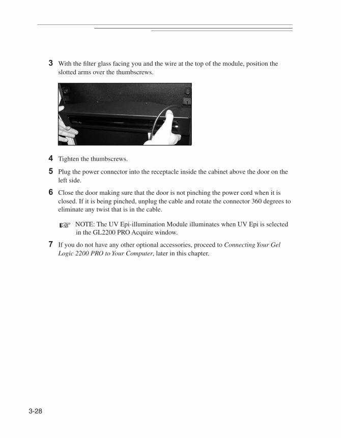
3-28
3 With the filter glass facing you and the wire at the top of the module, position the slotted arms over the thumbscrews.
4 Tighten the thumbscrews.
5 Plug the power connector into the receptacle inside the cabinet above the door on the left side.
6 Close the door making sure that the door is not pinching the power cord when it is closed. If it is being pinched, unplug the cable and rotate the connector 360 degrees to eliminate any twist that is in the cable.
☞ NOTE: The UV Epi-illumination Module illuminates when UV Epi is selected in the GL2200 PRO Acquire window.
7 If you do not have any other optional accessories, proceed to Connecting Your Gel Logic 2200 PRO to Your Computer, later in this chapter.
FPO
Setting
Up
3
Installing the UV Safety ShieldThe UV Safety Shield is designed to limit your exposure to UV when using the UV transilluminator for non-imaging applications such as viewing gels or cutting bands.
DANGER—Ultraviolet radiation emitted from this product. Avoid exposure. ALWAYS WEAR PROTECTIVE CLOTHING. EXPOSURE MAY CAUSE PREMATURE AGING OF THE SKIN AND CANCER. ALWAYS WEAR PROTECTIVE EYEWEAR; FAILURE TO DO SO MAY RESULT IN SEVERE BURNS OR LONG TERM INJURY TO EYE. Never look directly into the lamp. Exposure can cause eye and skin allergy and allergic reactions. Medications or cosmetics may increase your sensitivity to ultraviolet radiation. Consult physician before operating this product if you are using medications or have a history of skin problems or believe yourself especially sensitive to sunlight. For Laboratory Use Only.
The UV source does not operate when the door is open. Do not attempt to override this feature.
Discontinue use if the Platen is damaged or broken.
1 Open the front door of the GL2200 PRO Imaging Cabinet.
2 Use the handle to pull out the UV transilluminator until it stops.
3 Fully insert the lower edge of the safety shield in the slots in the two (2) black support brackets.
☞ NOTE: The Gel Tray provides a cutting surface for excising bands from your gel when using the optional UV Safety Shield.
☞ NOTE: The UV Transilluminator illuminates when UV Trans is selected in the GL2200 PRO Acquire window and you press the switch on the front of the Transilluminator.
4 If you do not have any other optional accessories, proceed to Connecting Your Gel Logic 2200 PRO to Your Computer, later in this chapter.
3-29

3-30
Connecting Your Gel Logic 2200 PRO to Your Computer
The Carestream Gel Logic 2200 PRO Imaging System communicates with the computer via an ethernet connection. As most computers are ordinarily equipped with a single ethernet port, which is usually dedicated to connection to an intranet or directly to the internet, the mode by which the Gel Logic 2200 PRO connects with the computer may vary.
✔ If a Windows-based computer was purchased with your GL2200 PRO from Carestream Molecular Imaging or your Carestream Molecular Imaging dealer, proceed to Installing Your Gel Logic 2200 PRO System with Carestream Windows-Based Computer.
✔ If you will use your GL2200 PRO with an existing Windows-based computer or a new computer not purchased from Carestream Molecular Imaging or your Carestream Molecular Imaging dealer, a mutiport gigabit desktop switch is supplied with your GL2200 PRO system. Proceed to Installing Your Gel Logic 2200 PRO System with Your Existing Windows XP-Based Computer or Installing Your Gel Logic 2200 PRO System with Your Existing Window Vista-Based Computer or Installing Your Gel Logic 2200 PRO System with Your Existing Windows 7-Based Computer, later in this chapter.
✔ If a Macintosh computer was purchased with your GL2200 PRO from Carestream Molecular Imaging or your Carestream Molecular Imaging dealer, proceed to Installing Your Gel Logic 2200 PRO System with Carestream Macintosh-Based Computer, later in this chapter.
✔ If you will use your GL2200 PRO with an existing or new Apple Mac Pro (tower), which are factory-equipped with dual ethernet ports, proceed to #8 in Installing Your Gel Logic 2200 PRO System with Carestream Macintosh-Based Computer, later in this chapter.
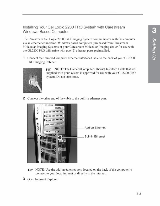
Setting
Up
3
Installing Your Gel Logic 2200 PRO System with Carestream Windows-Based ComputerThe Carestream Gel Logic 2200 PRO Imaging System communicates with the computer via an ethernet connection. Windows-based computers purchased from Carestream Molecular Imaging Systems or your Carestream Molecular Imaging dealer for use with the GL2200 PRO will arrive with two (2) ethernet ports preinstalled.
1 Connect the Camera/Computer Ethernet Interface Cable to the back of your GL2200 PRO Imaging Cabinet.
☞ NOTE: The Camera/Computer Ethernet Interface Cable that was supplied with your system is approved for use with your GL2200 PRO system. Do not substitute.
2 Connect the other end of the cable to the built-in ethernet port.
☞ NOTE: Use the add-on ethernet port, located on the back of the computer to connect to your local intranet or directly to the internet.
3 Open Intermet Explorer.
Add-on Ethernet
Built-in Ethernet
3-31

3-32
4 Enter http://192.168.2.100/ into the address bar. Click Go to or Enter. The System Contoller Welcome dialog box opens.
5 Click on the System Version tab and choose Recalibrate Lens. The lens calibration will run.
6 Exit the Web Browser.
7 Proceed to Launching Carestream Molecular Imaging Software with your Carestream Gel Logic 2200 PRO Imaging System, later in this chapter.

Setting
Up
3
Installing Your Gel Logic 2200 PRO System with Your Existing Windows XP-Based ComputerThe Carestream Gel Logic 2200 PRO imaging system communicates with the computer via an ethernet connection. As most computers are ordinarily equipped with a single ethernet port, which is usually dedicated to connection to an intranet or directly to the internet, a mutiport gigabit desktop switch is supplied with your GL2200 PRO system.
1 Connect a Camera/Computer Ethernet Interface Cable to the back of your GL2200 PRO Imaging Cabinet.
☞ NOTE: The Camera/Computer Ethernet Interface Cables that were supplied with your system are approved for use with your GL2200 PRO system. Do not substitute.
2 Attach the other end of that cable to one of the ports on the desktop ethernet switch.
3 Attach one end of the second cable Attach to another port on the switch and the other end to the computers built-in ethernet port.
☞ NOTE: The supplied ethernet switch has multiple ports. Use an available ethernet port on the switch to connect the computer to an intranet or directly to the internet.
4 Using the supplied power cable, plug the ethernet switch into an AC (MAINS) power source.
3-33
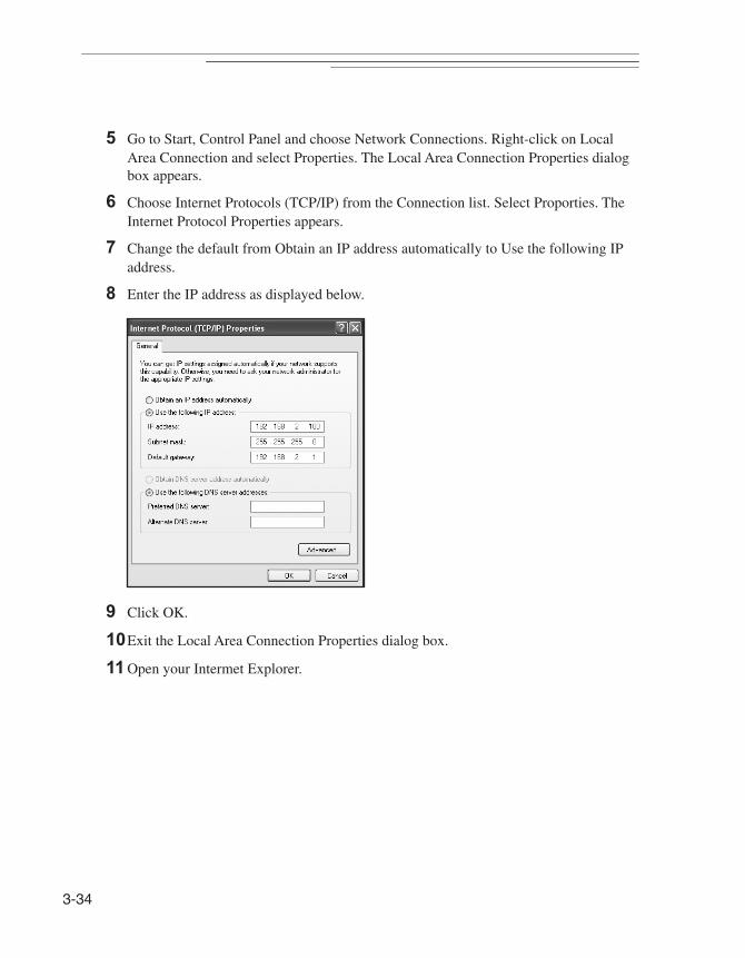
3-34
5 Go to Start, Control Panel and choose Network Connections. Right-click on Local Area Connection and select Properties. The Local Area Connection Properties dialog box appears.
6 Choose Internet Protocols (TCP/IP) from the Connection list. Select Proporties. The Internet Protocol Properties appears.
7 Change the default from Obtain an IP address automatically to Use the following IP address.
8 Enter the IP address as displayed below.
9 Click OK.
10Exit the Local Area Connection Properties dialog box.
11 Open your Intermet Explorer.
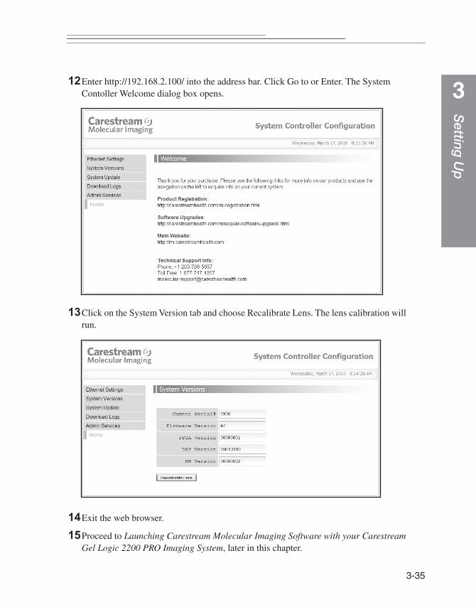
Setting
Up
3
12Enter http://192.168.2.100/ into the address bar. Click Go to or Enter. The SystemContoller Welcome dialog box opens.
13Click on the System Version tab and choose Recalibrate Lens. The lens calibration will run.
14Exit the web browser.
15Proceed to Launching Carestream Molecular Imaging Software with your Carestream Gel Logic 2200 PRO Imaging System, later in this chapter.
3-35
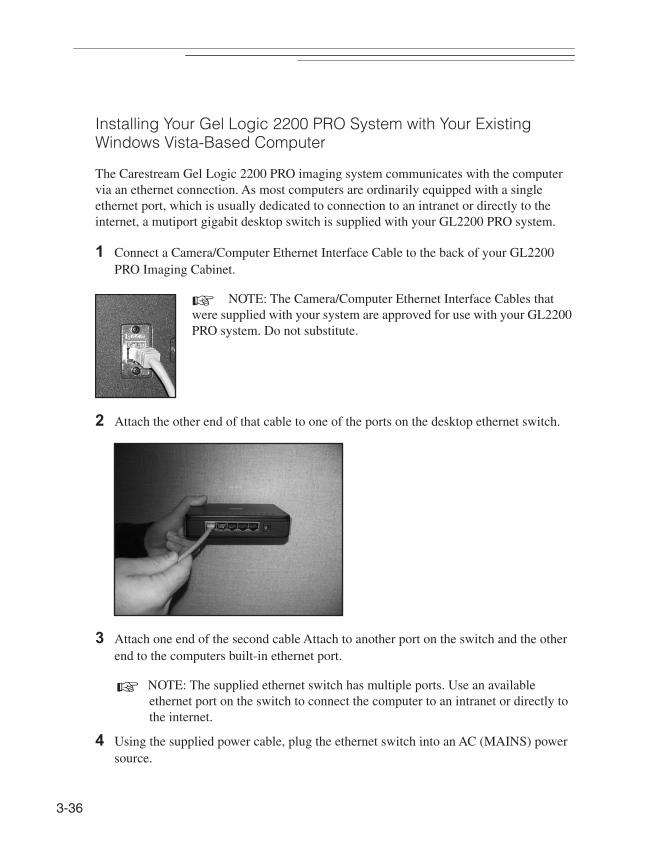
3-36
Installing Your Gel Logic 2200 PRO System with Your Existing Windows Vista-Based Computer
The Carestream Gel Logic 2200 PRO imaging system communicates with the computer via an ethernet connection. As most computers are ordinarily equipped with a single ethernet port, which is usually dedicated to connection to an intranet or directly to the internet, a mutiport gigabit desktop switch is supplied with your GL2200 PRO system.
1 Connect a Camera/Computer Ethernet Interface Cable to the back of your GL2200 PRO Imaging Cabinet.
☞ NOTE: The Camera/Computer Ethernet Interface Cables that were supplied with your system are approved for use with your GL2200 PRO system. Do not substitute.
2 Attach the other end of that cable to one of the ports on the desktop ethernet switch.
3 Attach one end of the second cable Attach to another port on the switch and the other end to the computers built-in ethernet port.
☞ NOTE: The supplied ethernet switch has multiple ports. Use an available ethernet port on the switch to connect the computer to an intranet or directly to the internet.
4 Using the supplied power cable, plug the ethernet switch into an AC (MAINS) power source.

Setting
Up
3
5 Go to Start, Control Panel and choose Network and Internet. Right-click on Local AreaConnection and select Properties.
6 A User Account Control window appears. Windows Vista requires the user to have Administrator privileges to continue. Click Continue.
7 The Local Area Connection Properties dialog box appears. Choose Internet Protocol Version 4 (TCP/IPv4) from the Connection list. Select Proporties.
8 The Internet Protocol Properties appears. Change the default from Obtain an IP address automatically to Use the following IP Address.
9 Enter the IP address as displayed below.
10Click OK.
11 Exit the Local Area Connection Properties dialog box.
12Open Intermet Explorer.
3-37
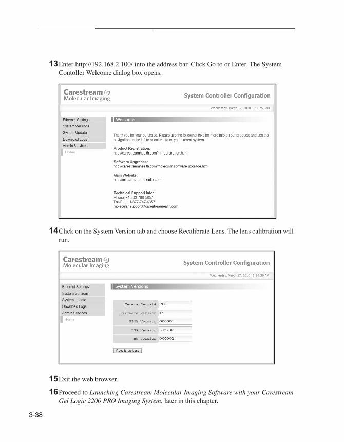
3-38
13Enter http://192.168.2.100/ into the address bar. Click Go to or Enter. The System Contoller Welcome dialog box opens.
14Click on the System Version tab and choose Recalibrate Lens. The lens calibration will run.
15Exit the web browser.
16Proceed to Launching Carestream Molecular Imaging Software with your Carestream Gel Logic 2200 PRO Imaging System, later in this chapter.
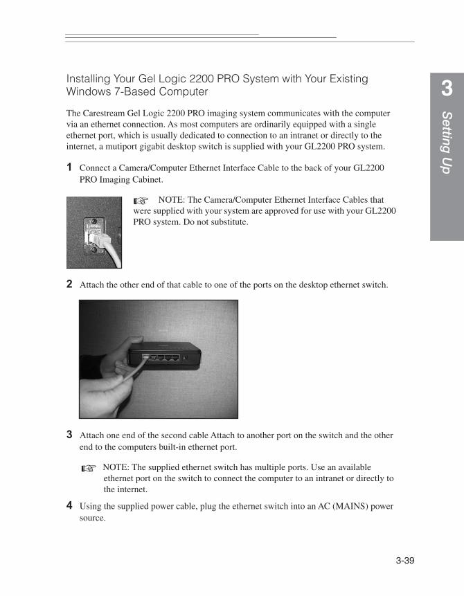
Setting
Up
3
Installing Your Gel Logic 2200 PRO System with Your Existing Windows 7-Based ComputerThe Carestream Gel Logic 2200 PRO imaging system communicates with the computer via an ethernet connection. As most computers are ordinarily equipped with a single ethernet port, which is usually dedicated to connection to an intranet or directly to the internet, a mutiport gigabit desktop switch is supplied with your GL2200 PRO system.
1 Connect a Camera/Computer Ethernet Interface Cable to the back of your GL2200 PRO Imaging Cabinet.
☞ NOTE: The Camera/Computer Ethernet Interface Cables that were supplied with your system are approved for use with your GL2200 PRO system. Do not substitute.
2 Attach the other end of that cable to one of the ports on the desktop ethernet switch.
3 Attach one end of the second cable Attach to another port on the switch and the other end to the computers built-in ethernet port.
☞ NOTE: The supplied ethernet switch has multiple ports. Use an available ethernet port on the switch to connect the computer to an intranet or directly to the internet.
4 Using the supplied power cable, plug the ethernet switch into an AC (MAINS) power source.
3-39

3-40
5 Go to Start, Control Panel and choose Network and Internet. Select Network and Sharing Center and choose click Change adaptor setting. The Network Connections dialog box appears.
6 Right-click on Local Area Connection and select Properties. The Local Area Connection Properties dialog box appears.
7 Choose Internet Protocol Version 4 (TCP/IPv4) from the Connection list. Select Proporties. The Internet Protocol Properties appears.
8 Change the default from Obtain an IP address automatically to Use the following IP address.
9 Enter the IP address as displayed below.
10Click OK.
11 Close the Local Area Connection Properties dialog box.
12Open your Intermet Explorer.

Setting
Up
3
13Enter http://192.168.2.100/ into the address bar. Click Go to or Enter. The SystemContoller Welcome dialog box opens.
14Click on the System Version tab and choose Recalibrate Lens. The lens calibration will run.
15Exit the web browser.
16Proceed to Launching Carestream Molecular Imaging Software with your Carestream Gel Logic 2200 PRO Imaging System, later in this chapter.
3-41
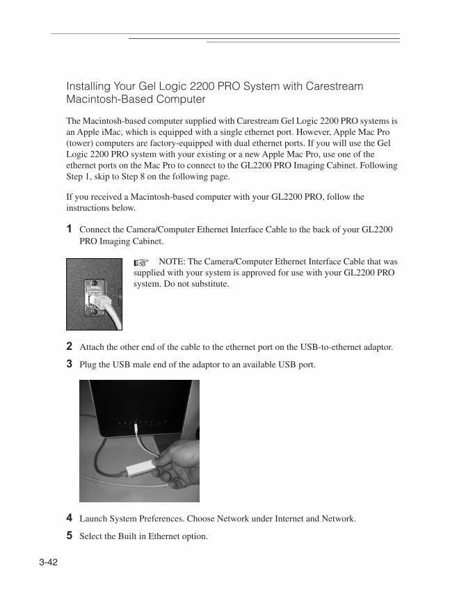
3-42
Installing Your Gel Logic 2200 PRO System with Carestream Macintosh-Based Computer
The Macintosh-based computer supplied with Carestream Gel Logic 2200 PRO systems is an Apple iMac, which is equipped with a single ethernet port. However, Apple Mac Pro (tower) computers are factory-equipped with dual ethernet ports. If you will use the Gel Logic 2200 PRO system with your existing or a new Apple Mac Pro, use one of the ethernet ports on the Mac Pro to connect to the GL2200 PRO Imaging Cabinet. Following Step 1, skip to Step 8 on the following page.
If you received a Macintosh-based computer with your GL2200 PRO, follow the instructions below.
1 Connect the Camera/Computer Ethernet Interface Cable to the back of your GL2200 PRO Imaging Cabinet.
☞ NOTE: The Camera/Computer Ethernet Interface Cable that was supplied with your system is approved for use with your GL2200 PRO system. Do not substitute.
2 Attach the other end of the cable to the ethernet port on the USB-to-ethernet adaptor.
3 Plug the USB male end of the adaptor to an available USB port.
4 Launch System Preferences. Choose Network under Internet and Network.
5 Select the Built in Ethernet option.
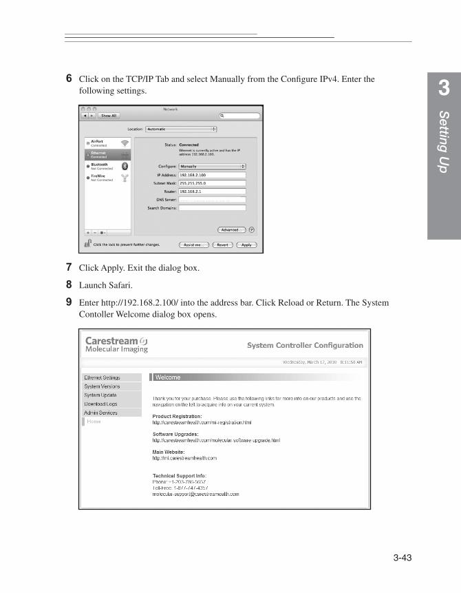
Setting
Up
3
6 Click on the TCP/IP Tab and select Manually from the Configure IPv4. Enter thefollowing settings.
7 Click Apply. Exit the dialog box.
8 Launch Safari.
9 Enter http://192.168.2.100/ into the address bar. Click Reload or Return. The System Contoller Welcome dialog box opens.
3-43
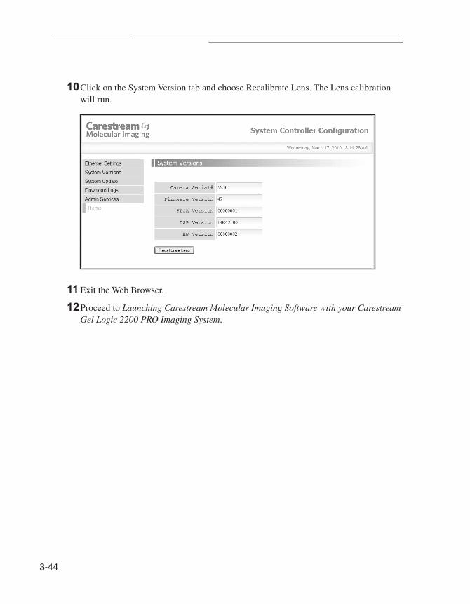
3-44
10Click on the System Version tab and choose Recalibrate Lens. The Lens calibration will run.
11 Exit the Web Browser.
12Proceed to Launching Carestream Molecular Imaging Software with your Carestream Gel Logic 2200 PRO Imaging System.
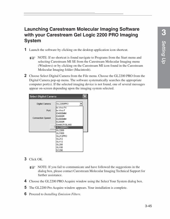
Setting
Up
3
Launching Carestream Molecular Imaging Software with your Carestream Gel Logic 2200 PRO Imaging System1 Launch the software by clicking on the desktop application icon shortcut.
☞ NOTE: If no shortcut is found navigate to Programs from the Start menu and selecting Carestream MI SE from the Carestream Molecular Imaging menu (Windows) or by clicking on the Carestream MI icon found in the Carestream Molecular Imaging folder (Macintosh).
2 Choose Select Digital Camera from the File menu. Choose the GL2200 PRO from the Digital Camera pop-up menu. The software systematically searches the appropriate computer port(s). If the selected imaging device is not found, one of several messages appear on-screen depending upon the imaging system selected.
3 Click OK.
☞ NOTE: If you fail to communicate and have followed the suggestions in the dialog box, please contact Carestream Molecular Imaging Technical Support for further assistance.
4 Choose the GL2200 PRO Acquire window using the Select Your System dialog box.
5 The GL2200 Pro Acquire window appears. Your installation is complete.
6 Proceed to Installing Emission Filters.
3-45
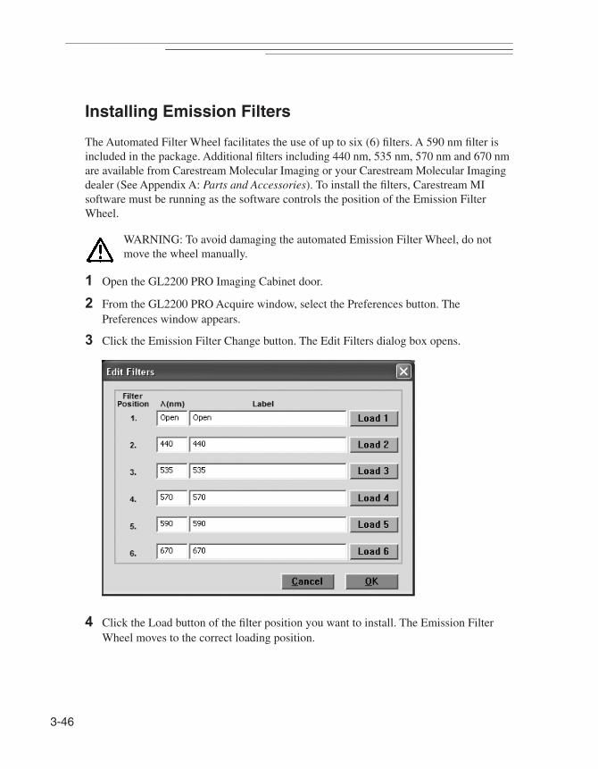
3-46
Installing Emission Filters
The Automated Filter Wheel facilitates the use of up to six (6) filters. A 590 nm filter is included in the package. Additional filters including 440 nm, 535 nm, 570 nm and 670 nm are available from Carestream Molecular Imaging or your Carestream Molecular Imaging dealer (See Appendix A: Parts and Accessories). To install the filters, Carestream MI software must be running as the software controls the position of the Emission Filter Wheel.
WARNING: To avoid damaging the automated Emission Filter Wheel, do not move the wheel manually.
1 Open the GL2200 PRO Imaging Cabinet door.
2 From the GL2200 PRO Acquire window, select the Preferences button. The Preferences window appears.
3 Click the Emission Filter Change button. The Edit Filters dialog box opens.
4 Click the Load button of the filter position you want to install. The Emission Filter Wheel moves to the correct loading position.

Setting
Up
3
5 Carefully position the filter, thread side down into the Filter Tool while pressing firmlyon the Filter Wheel Tool handle. Be careful not to touch the filter element. Gently release your grip as you position the filter in the filter wheel. The filter will drop into position.
6 Click OK.
7 Enter the wavelength and a label for the filter you have loaded in the Wavelength and Label text edit box.
8 Repeat Steps 4–7 for all the filters that you want to install.
9 Click OK.
The table below defines the appropriate filter for many common stains and dyes:
10Proceed to the next section, Focusing the Camera.
Dye/Stain Filter (nm)
Coomassie Blue 590 or none
Ethidium Bromide 590
Fluorescein 535
Oregon Green 535
Gel Star 535
SYPRO Orange 590
SYBR Green 535
SYBR Gold 535
3-47
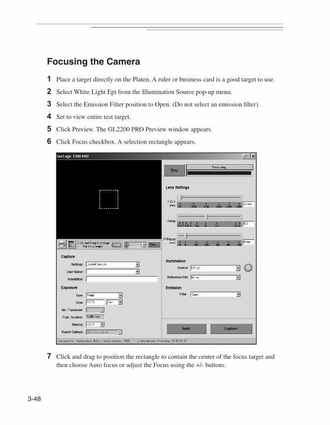
3-48
Focusing the Camera
1 Place a target directly on the Platen. A ruler or business card is a good target to use.
2 Select White Light Epi from the Illumination Source pop-up menu.
3 Select the Emission Filter position to Open. (Do not select an emission filter).
4 Set to view entire test target.
5 Click Preview. The GL2200 PRO Preview window appears.
6 Click Focus checkbox. A selection rectangle appears.
7 Click and drag to position the rectangle to contain the center of the focus target and then choose Auto focus or adjust the Focus using the +/- buttons.

Setting
Up
3
☞ NOTE: Hold down the Escape key if you find that the fine focus has passed through the best focus value. Auto Focus will use the best focus value up to the time you pressed the Auto Focus button again.8 You are now ready to begin capturing images. To learn about capturing images with the GL2200 PRO, proceed to Chapter 4: Capturing Images.
3-49

3-50
Cap
turing Im
ages
4
Capturing Images
Once your Carestream Gel Logic 2200 PRO Imaging System (GL2200 PRO) has been set up and Carestream Molecular Imaging Software (Carestream MI) is installed, you are ready to capture high quality digital images.
The GL2200 PRO supports several image capture methods including single capture exposure, multiple capture exposure (accumulated into a single file or as separate files) and time lapse exposures. Using these exposure modes, the minimum and maximum exposure times are 0.001 second and 16 seconds, respectively.
✔ Using GL2200 PRO, you can document your laboratory experiments with floating point accuracy and analyze images:
— DNA, RNA and protein electrophoresis gels, including gels stained with ethidium bromide, SYPRO Orange, SYBR Green, SYBR Gold, and Coomassie Blue
— Chemiluminescent blots
— Microtiter plate assays
— Colony plates
— Plaque screening
— Thin-layer chromatography plates
✔ Generate a quick print of your image.
✔ Annotate, analyze, and print your images.
4-1
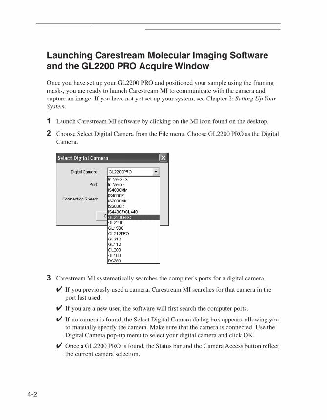
4-2
Launching Carestream Molecular Imaging Software and the GL2200 PRO Acquire Window
Once you have set up your GL2200 PRO and positioned your sample using the framing masks, you are ready to launch Carestream MI to communicate with the camera and capture an image. If you have not yet set up your system, see Chapter 2: Setting Up Your System.
1 Launch Carestream MI software by clicking on the MI icon found on the desktop.
2 Choose Select Digital Camera from the File menu. Choose GL2200 PRO as the Digital Camera.
3 Carestream MI systematically searches the computer's ports for a digital camera.
✔ If you previously used a camera, Carestream MI searches for that camera in the port last used.
✔ If you are a new user, the software will first search the computer ports.
✔ If no camera is found, the Select Digital Camera dialog box appears, allowing you to manually specify the camera. Make sure that the camera is connected. Use the Digital Camera pop-up menu to select your digital camera and click OK.
✔ Once a GL2200 PRO is found, the Status bar and the Camera Access button reflect the current camera selection.

Cap
turing Im
ages
4
4 The GL2200 PRO Acquire window appears.
5 You are ready to begin imaging. Proceed to Preparing for Image Capture.
4-3
4-4
Preparing for Image Capture
Your GL2200 PRO should be installed, if it is has not yet been installed, see Chapter 3: Setting up the System.
Be sure that the imaging surface is clean prior to any sample placement. Dust, particles or scratches on the surface may introduce artifacts in your data. Extra care should be taken when cleaning the surface to avoid scratches.
1 Open the GL2200 PRO Imaging Cabinet Door.
2 Place the sample in the center of the appropriate imaging surface.
✔ Chemiluminescent sample—place the sample on the Black Backdrop.
✔ For White Light Transillumination using the optional accessory—place the sample on the fold-down White Light Transilluminator Module inside the cabinet.
✔ For UV Transillumination—place the sample on the UV Transilluminator Platen.
✔ White Light Epi-illumination—place the sample on the Epi-White/Black Backdrop Screen positioned in the Gel Tray. Place the sample on the black or white side to achieve the best contrast, i.e., Coomassie stained gels are best imaged on the white side.
✔ UV Epi-illumination—place the sample on the black side of the Epi-White/Black Backdrop Screen positioned in the Gel Tray.
☞ NOTE: Special care should be taken if your sample is dry. Ensure a dry surface by a quick ethanol wipe.
☞ NOTE: Do not use metal utensils or tweezers since they may scratch and permanently damage the glass surface.
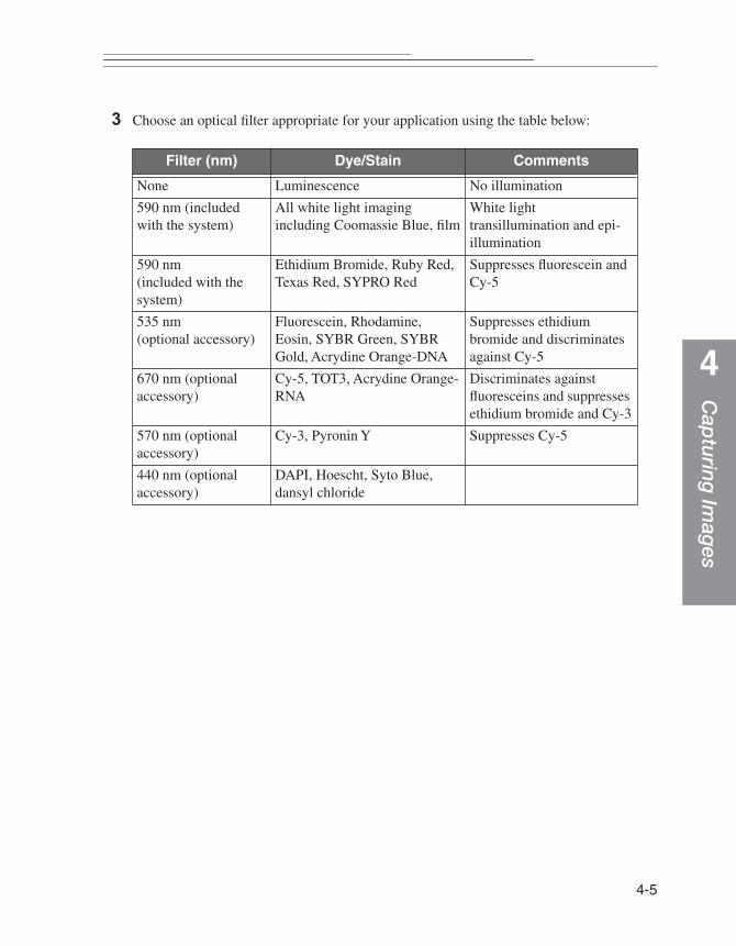
Cap
turing Im
ages
4
3 Choose an optical filter appropriate for your application using the table below:
Filter (nm) Dye/Stain Comments
None Luminescence No illumination
590 nm (included with the system)
All white light imaging including Coomassie Blue, film
White light transillumination and epi-illumination
590 nm(included with the system)
Ethidium Bromide, Ruby Red, Texas Red, SYPRO Red
Suppresses fluorescein and Cy-5
535 nm(optional accessory)
Fluorescein, Rhodamine, Eosin, SYBR Green, SYBR Gold, Acrydine Orange-DNA
Suppresses ethidium bromide and discriminates against Cy-5
670 nm (optional accessory)
Cy-5, TOT3, Acrydine Orange-RNA
Discriminates against fluoresceins and suppresses ethidium bromide and Cy-3
570 nm (optional accessory)
Cy-3, Pyronin Y Suppresses Cy-5
440 nm (optional accessory)
DAPI, Hoescht, Syto Blue, dansyl chloride
4-5
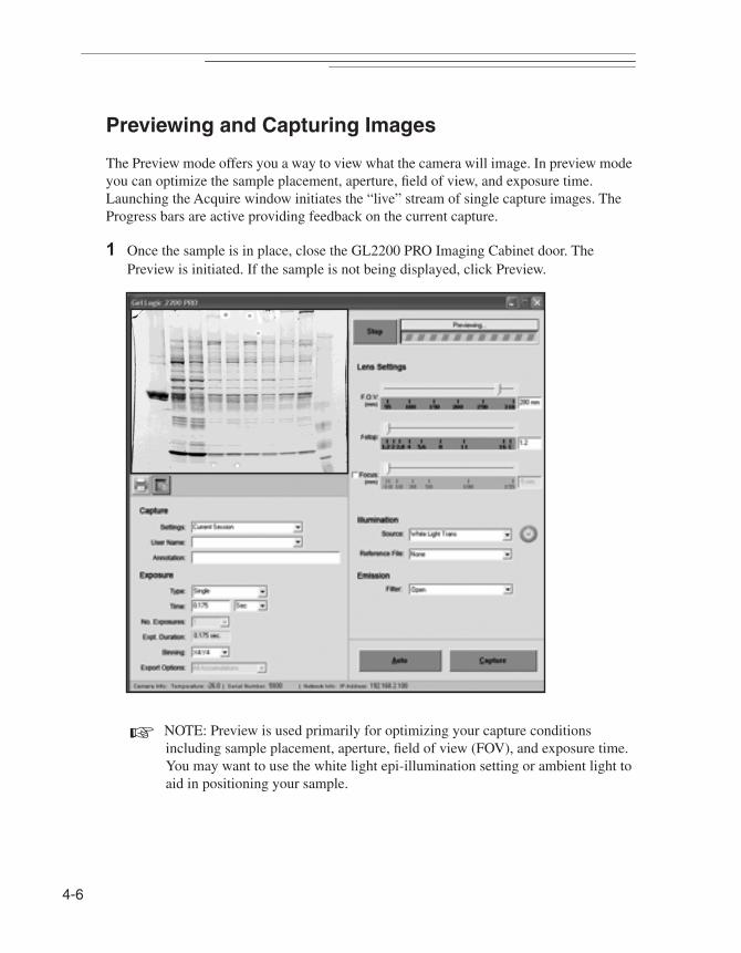
4-6
Previewing and Capturing Images
The Preview mode offers you a way to view what the camera will image. In preview mode you can optimize the sample placement, aperture, field of view, and exposure time. Launching the Acquire window initiates the “live” stream of single capture images. The Progress bars are active providing feedback on the current capture.
1 Once the sample is in place, close the GL2200 PRO Imaging Cabinet door. The Preview is initiated. If the sample is not being displayed, click Preview.
☞ NOTE: Preview is used primarily for optimizing your capture conditions including sample placement, aperture, field of view (FOV), and exposure time. You may want to use the white light epi-illumination setting or ambient light to aid in positioning your sample.
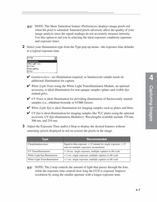
Cap
turing Im
ages
4
☞ NOTE: The Show Saturation feature (Preferences) displays image pixels red when the pixel is saturated. Saturated pixels adversely affect the quality of your image analysis since the signal readings do not accurately measure intensity. Use this option to aid you in selecting the ideal exposure conditions (aperture and exposure time).
2 Select your illumination type from the Type pop-up menu—the exposure time defaults to a typical exposure time.
✔ Luminescence—no illumination required, as luminescent sample needs no additional illumination for capture.
✔ White Light Trans using the White Light Transilluminator Module, an optional accessory, is ideal illumination for non-opaque samples (plates and visible dye stained gels).
✔ UV Trans is ideal illumination for providing illumination of fluorescently stained samples (i.e., ethidium bromide or SYBR Green).
✔ White Light Epi is ideal illumination for imaging samples such as plates and blots.
✔ UV Epi is ideal illumination for imaging samples like TLC plates using the optional accessory UV Epi-illumination Module(s). Wavelengths available include 370 nm, 306 nm, and 254 nm.
3 Adjust the Exposure Time and/or f-Stop to display the desired features without
saturating (pixels displayed in red on-screen) the pixels in the image.
☞ NOTE: The f-stop controls the amount of light that passes through the lens, while the exposure time controls how long the CCD is exposed. Improve resolution by using the smaller aperture with a longer exposure time.
Type Recommended
Chemiluminescence Equal to film exposure. < 15 minute for single exposure, > 15 min for multiple exposures accumulated
UV Transillumination 1–10 sec. single exposure, multiple captures to fill scale
White Light Epi-Illumination < 1 sec. single exposure, multiple captures to fill scale
White Light Transillumination < 1 sec. single exposure, multiple captures to fill scale
4-7
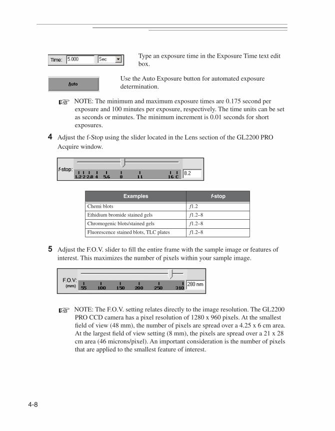
4-8
Type an exposure time in the Exposure Time text edit box.
Use the Auto Exposure button for automated exposure determination.
☞ NOTE: The minimum and maximum exposure times are 0.175 second per exposure and 100 minutes per exposure, respectively. The time units can be set as seconds or minutes. The minimum increment is 0.01 seconds for short exposures.
4 Adjust the f-Stop using the slider located in the Lens section of the GL2200 PRO
Acquire window.
5 Adjust the F.O.V. slider to fill the entire frame with the sample image or features of interest. This maximizes the number of pixels within your sample image.
☞ NOTE: The F.O.V. setting relates directly to the image resolution. The GL2200 PRO CCD camera has a pixel resolution of 1280 x 960 pixels. At the smallest field of view (48 mm), the number of pixels are spread over a 4.25 x 6 cm area. At the largest field of view setting (8 mm), the pixels are spread over a 21 x 28 cm area (46 microns/pixel). An important consideration is the number of pixels that are applied to the smallest feature of interest.
Examples f-stop
Chemi blots f1.2
Ethidium bromide stained gels f1.2–8
Chromogenic blots/stained gels f1.2–8
Fluorescence stained blots, TLC plates f1.2–8
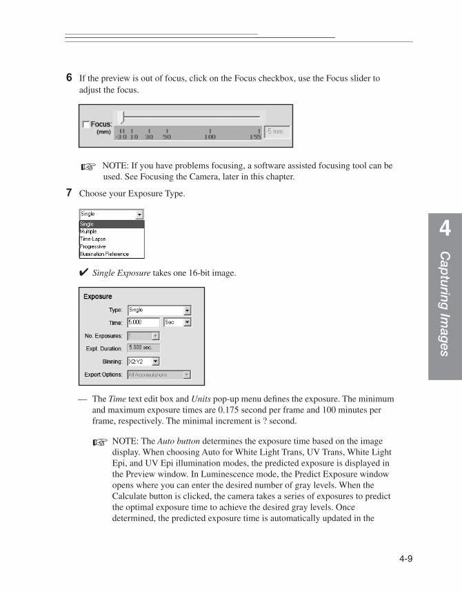
Cap
turing Im
ages
4
6 If the preview is out of focus, click on the Focus checkbox, use the Focus slider to adjust the focus.
☞ NOTE: If you have problems focusing, a software assisted focusing tool can be used. See Focusing the Camera, later in this chapter.
7 Choose your Exposure Type.
✔ Single Exposure takes one 16-bit image.
— The Time text edit box and Units pop-up menu defines the exposure. The minimum and maximum exposure times are 0.175 second per frame and 100 minutes per frame, respectively. The minimal increment is ? second.
☞ NOTE: The Auto button determines the exposure time based on the image display. When choosing Auto for White Light Trans, UV Trans, White Light Epi, and UV Epi illumination modes, the predicted exposure is displayed in the Preview window. In Luminescence mode, the Predict Exposure window opens where you can enter the desired number of gray levels. When the Calculate button is clicked, the camera takes a series of exposures to predict the optimal exposure time to achieve the desired gray levels. Once determined, the predicted exposure time is automatically updated in the
4-9
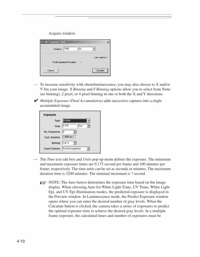
4-10
Acquire window.
— To increase sensitivity with chemiluminescence, you may also choose to X and/or Y bin your image. X Binning and Y Binning options allow you to select from None (no binning), 2 pixel, or 4 pixel binning in one or both the X and Y directions.
✔ Multiple Exposure (Final Accumulation) adds successive captures into a single accumulated image.
— The Time text edit box and Units pop-up menu defines the exposure. The minimum and maximum exposure times are 0.175 second per frame and 100 minutes per frame, respectively. The time units can be set as seconds or minutes. The maximum duration time is 3200 minutes. The minimal increment is ? second.
☞ NOTE: The Auto button determines the exposure time based on the image display. When choosing Auto for White Light Trans, UV Trans, White Light Epi, and UV Epi illumination modes, the predicted exposure is displayed in the Preview window. In Luminescence mode, the Predict Exposure window opens where you can enter the desired number of gray levels. When the Calculate button is clicked, the camera takes a series of exposures to predict the optimal exposure time to achieve the desired gray levels. In a multiple frame exposure, the calculated times and number of exposures must be
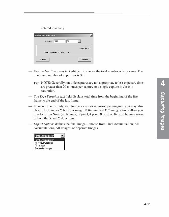
Cap
turing Im
ages
4
entered manually.
— Use the No. Exposures text edit box to choose the total number of exposures. The maximum number of exposures is 32.
☞ NOTE: Generally multiple captures are not appropriate unless exposure times are greater than 20 minutes per capture or a single capture is close to saturation.
— The Expt Duration text field displays total time from the beginning of the first frame to the end of the last frame.
— To increase sensitivity with luminescence or radioisotopic imaging, you may also choose to X and/or Y bin your image. X Binning and Y Binning options allow you to select from None (no binning), 2 pixel, 4 pixel, 8 pixel or 16 pixel binning in one or both the X and Y directions.
— Export Options defines the final image—choose from Final Accumulation, All Accumulations, All Images, or Separate Images.
4-11

4-12
✔ Time Lapse Exposure provides exposures at set intervals.
— The Exposure Time defines the exposure. The minimum and maximum exposure times are 0.175 seconds per frame and 100 minutes per frame, respectively. The time units can be set as seconds or minutes.The maximum duration time is 3200 minutes. The minimal increment is ? second.
☞ NOTE: The Auto button determines the exposure time based on the image display. When choosing Auto for White Light Trans, UV Trans, White Light Epi, and UV Epi illumination modes, the predicted exposure is displayed in the Preview window. In Luminescence mode, the Predict Exposure window opens where you can enter the desired number of gray levels. When the Calculate button is clicked, the camera takes a series of exposures to predict the optimal exposure time to achieve the desired gray levels. In a multiple frame exposure, the calculated times and number of exposures must be entered manually.
— The Interval is the time interval between the beginning of one exposure and the beginning of the next exposure. The minimum and maximum intervals are 5 seconds and 200 hours, respectively.
☞ NOTE: An interval must be at least 1 second greater than an exposure time.
— Stop After determines when to stop time lapse captures. You can set stop criteria

Cap
turing Im
ages
4
based on experimental duration or by the number of frames. The maximum duration time is 3200 minutes. The maximum number of image frames that may be captured is ?.
— To increase sensitivity with luminescence or radioisotopic imaging, you may also choose to X and/or Y bin your image. X Binning and Y Binning options allow you to select from None (no binning), 2 pixel, 4 pixel, 8 pixel or 16 pixel binning in one or both the X and Y directions.
✔ The Progressive Exposure option is designed to take a continuous sequence of exposures at different exposure times.
— The Time text edit box and Units pop-up menu defines the exposure. The minimum and maximum exposure times are 0.175 second per frame and 100 minutes per frame, respectively. The minimal increment is ? second.
☞ NOTE: NOTE: The Auto button determines the exposure time based on the image display. When choosing Auto for White Light Trans, UV Trans, White Light Epi, and UV Epi illumination modes, the predicted exposure is displayed in the Preview window. In Luminescence mode, the Predict Exposure window opens where you can enter the desired number of gray levels. When the Calculate button is clicked, the camera takes a series of exposures to predict the optimal exposure time to achieve the desired gray levels. In a multiple frame exposure, the calculated times and number of exposures must be entered manually.
4-13
4-14
— The Increment determines each new exposure time. The smallest increment for exposures is ? second.
— Use the No. Exposures text edit box to choose the total number of exposures. The maximum number of exposures is 32.
— To increase sensitivity with chemiluminescence, you may also choose to X and/or Y bin your image. X Binning and Y Binning options allow you to select from None (no binning), 2 pixel, or 4 pixel binning in one or both the X and Y directions.
8 To capture an image—click Capture or Quick Print.
The Capture button initiates image acquisition. Once acquired, files can be analyzed, annotated and printed.
The Quick Print button sends the image directly to your printer and no copy of the image is saved.
Cap
turing Im
ages
4
Custom Capture Settings
You can speed up the capture process by creating custom capture settings for the various types of experiments or specific personal preferences. Once saved, Carestream MI remembers the camera settings which include:
✔ Exposure time
✔ Number of exposures
✔ Illumination settings
✔ f-Stop, field of view (FOV)
✔ Emission filter
✔ Image orientation
✔ Preferences
✔ Rotation
✔ Saturation levels
✔ Lens, warping, and illumination correction
✔ X and/or Y binning
☞ IMPORTANT: Settings will NOT save the Aperture, Field of View, Focus, or User Name or Annotations.
Saving Custom User Settings
1 Make all your selections from within the GL2200 PRO Acquire window.
2 Choose the Save Settings from the Settings pop-up menu. A File Name dialog box appears.
3 Enter a name to describe your custom settings.
4 Click OK. The settings are saved and will appear in the list of available settings.
☞ NOTE: If you choose a custom acquire setting, and then make modifications to the custom settings, they will not be saved unless you update the custom setting by selecting Update Settings from the Settings pop-up menu.
☞ NOTE: Custom settings are saved as individual files in C:\Program Files\Molecular Imaging\ MI\Application\GL2200PRO\GL2200PRO_Settings (Windows) or in the Molecular Imaging\MI\Application\MI Extensions\GL2200PRO_Settings (Macintosh) subfolders.
4-15
4-16
Updating Custom User Settings
1 Select a custom setting from the Settings pop-up menu.
2 Modify settings as desired.
3 Choose Update Settings in the Settings pop-up menu.
☞ NOTE: The GL2200 PRO factory defaults cannot be updated.
Deleting Custom User Settings
1 Select a custom setting from the Settings pop-up menu.
2 Choose Delete Settings.
☞ NOTE: The GL2200 PRO factory defaults cannot be deleted.
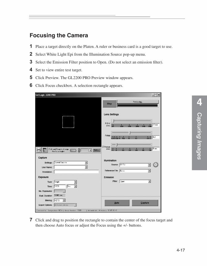
Cap
turing Im
ages
4
Focusing the Camera
1 Place a target directly on the Platen. A ruler or business card is a good target to use.
2 Select White Light Epi from the Illumination Source pop-up menu.
3 Select the Emission Filter position to Open. (Do not select an emission filter).
4 Set to view entire test target.
5 Click Preview. The GL2200 PRO Preview window appears.
6 Click Focus checkbox. A selection rectangle appears.
7 Click and drag to position the rectangle to contain the center of the focus target and then choose Auto focus or adjust the Focus using the +/- buttons.
4-17

4-18
☞ NOTE: Hold down the Escape key if you find that the fine focus has passed through the best focus value. Auto Focus will use the best focus value up to the time you pressed the Auto Focus button again.
8 You are now ready to begin capturing images.
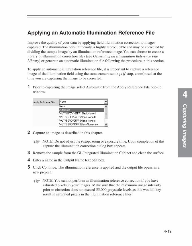
Cap
turing Im
ages
4
Applying an Automatic Illumination Reference File
Improve the quality of your data by applying field illumination correction to images captured. The illumination non-uniformity is highly reproducible and may be corrected by dividing the sample image by an illumination reference image. You can choose to create a library of illumination correction files (see Generating an Illumination Reference File Library) or generate an automatic illumination file following the procedure in this section.
To apply an automatic illumination reference file, it is important to capture a reference image of the illumination field using the same camera settings (f-stop, zoom) used at the time you are capturing the image to be corrected.
1 Prior to capturing the image select Automatic from the Apply Reference File pop-up window.
2 Capture an image as described in this chapter.
☞ NOTE: Do not adjust the f-stop, zoom or exposure time. Upon completion of the capture the illumination correction dialog box appears.
3 Remove the sample from the GL Integrated Illumination Cabinet and clean the surface.
4 Enter a name in the Output Name text edit box.
5 Click Continue. The illumination reference is applied and the output file opens as a new project.
☞ NOTE: You cannot perform an illumination reference correction if you have saturated pixels in your images. Make sure that the maximum image intensity prior to cirrection does not exceed 55,000 grayscale levels as this would likey result in saturated pixels in the illumination reference files.
4-19
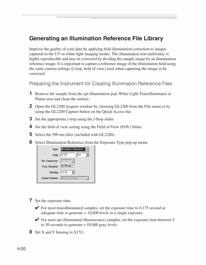
4-20
Generating an Illumination Reference File Library
Improve the quality of your data by applying field illumination correction to images captured in the UV or white light imaging modes. The illumination non-uniformity is highly reproducible and may be corrected by dividing the sample image by an illumination reference image. It is important to capture a reference image of the illumination field using the same camera settings (f-stop, field of view) used when capturing the image to be corrected.
Preparing the Instrument for Creating Illumination Reference Files
1 Remove the sample from the epi-illumination pad, White Light Transilluminator or Platen area and clean the surface.
2 Open the GL2200 Acquire window by choosing GL2200 from the File menu or by using the GL2200 Capture button on the Quick Access bar.
3 Set the appropriate f-stop using the f-Stop slider.
4 Set the field of view setting using the Field of View (FOV) Slider.
5 Select the 590 nm filter (included with GL2200).
6 Select Illumination Reference from the Exposure Type pop-up menu.
7 Set the exposure time.
✔ For most transilluminated samples, set the exposure time to 0.175 second or adequate time to generate > 10,000 levels in a single exposure.
✔ For most epi-illuminated (fluorescence) samples, set the exposure time between 5 to 30 seconds to generate > 10,000 gray levels.
8 Set X and Y binning to X1Y1.

Cap
turing Im
ages
4
9 Select the illumination source.
10Click the Capture button. A dialog box appears asking you to enter a name for the file (a default name is automatically entered using the selected illumination source, f-stop, and FOV settings).
11 Click OK. The file is saved.
12The illumination reference file opens as a file and the GL2200 Acquire window appears. The newly created illumination reference file is now available to apply to a new image.
☞ NOTE: Illumination reference files may also be applied later in software using the Image Field Correction from the Edit menu.
☞ NOTE: Upon application, the illumination reference file does not alter the mean value of the image to which it is applied.
13Turn off the light source.
4-21

4-22
Adding an Annotation Bar to the Printed Image
You can tag your image with an Annotation bar which contains the time and date of the capture of the image, the exposure setting, sample type, and up to 48 characters of text. The text will appear on the long axis at the top of the image in 12 point Helvetica Bold as white text on a black background.
☞ NOTE: All items in the Annotation bar are separate objects once submitted to Carestream MI and displayed in the Annotations window. You can change the font style, color, or size prior to printing, however, the items are grouped. You must ungroup the items prior to editing.
1 Type text (up to 48 character) in the Add Annotation text edit box.
2 The Annotations bar is appended to the image upon printing.
☞ NOTE: Each time you take a picture the Add Annotation text edit box are cleared.
☞ NOTE: You can display or hide the Annotation bar by selecting the Show/Hide Annotation bar from the Annotations menu.
Cap
turing Im
ages
4
Using the Transilluminator for Non-Imaging Applications
The UV Transilluminator provides broadband UV ideal for visualizing or cutting out bands from fluorescent samples like ethidium bromide stained gels.
1 Place the sample on the UV transilluminator Platen.
✔ For UV transillumination—place the sample on the Platen or Gel Cutting Tray.
2 Insert the UV Safety Shield into the Safety Shield slots in the front of the UV transilluminator.
3 Press the UV transilluminator button located on the front of the transilluminator.
DANGER—Ultraviolet radiation emitted from this product. Avoid exposure. ALWAYS WEAR PROTECTIVE CLOTHING. EXPOSURE MAY CAUSE PREMATURE AGING OF THE SKIN AND CANCER. ALWAYS WEAR PROTECTIVE EYEWEAR; FAILURE TO DO SO MAY RESULT IN SEVERE BURNS OR LONG TERM INJURY TO EYE. Never look directly into the lamp. Exposure can cause eye and skin allergy and allergic reactions. Medications or cosmetics may increase your sensitivity to ultraviolet radiation. Consult physician before operating this product if you are using medications or have a history of skin problems or believe yourself especially sensitive to sunlight. For Laboratory Use Only.
The Safety Shield must be in place when the door is open and the UV Transilluminator is activated. UV will not be emitted at the Platen surface if the UV Safety Shield is not in place. Replace the UV Safety Shield if cracked or damaged.
Personal Protective Wear. If your hands are in close contact with the Platen surface or anywhere behind the UV Safety Shield, to prevent injury it is imperative that appropriate gloves be worn (i.e., nitrile). Latex gloves are also effective, however latex may present an allergic reaction in some individuals. In addition, long-sleeved lab coat or other tightly woven material will be effective in reducing UV exposures.
Protective eye wear should be worn by users when the Platen surface is pulled out.
4 When finished, remove the UV Safety Shield to disengage the UV transilluminator and turn off UV illumination.
4-23

4-24
5 Remove the sample from the cabinet or proceed with an imaging protocol.

4-25
Cap
turing Im
ages
4

4-26
Maintaining
5
Maintaining Your System
Your Carestream Gel Logic 2200 PRO Imaging System (GL2200 PRO) is a delicate piece of photographic equipment, requiring care and maintenance.
✔ To keep from damaging your GL2200 PRO Camera Assembly, avoid exposure to moisture and extreme temperatures
WARNING: The power cord is the primary disconnect device from the AC (MAINS) outlet. Always turn the main power switch off and disconnect the unit from the AC (MAINS) outlet before performing any service.
WARNING: When handling or using ammonia based spray cleaner, follow instructions noted in the Material Safety Data Sheet (MSDS).
WARNING: When cleaning your GL2200 PRO, we recommend that you wear impervious gloves, e.g., latex or nitrile.
5-1
5-2
Maintaining Your Carestream Gel Logic 2200 PRO Imaging Cabinet
The GL2200 PRO Imaging Cabinet is fabricated to facilitate easy cleaning. We recommend that you clean your cabinet and accessories regularly to keep them in good working order.
WARNING: The power cord is the primary disconnect device from the AC (MAINS) supply. Always turn the switch the cabinet off and disconnect the unit from the AC (MAINS) outlet before performing any maintenance.
Cleaning the Cabinet
The cabinet is designed for easy care.
✔ For material not contaminated with biological or radiological substances, wipe with a non-abrasive cleaner.
✔ For materials contaminated with biological substances, prepare a 5% bleach solution in water. Wipe down the cabinet with the bleach solution using a clean cloth or sponge. Wipe clean with water.
✔ For materials contaminated with radiological substances, decontaminate with a radioactive decontamination detergent, following manufacturer’s instructions and your institutional safety protocols for decontaminating and handling radioactive waste.
WARNING: Never use harsh or abrasive cleaners or organic solvents on the any parts of the system.
WARNING: When handling or using ammonia based spray cleaners, follow instructions noted in their Material Safety Data Sheet (MSDS).
WARNING: When cleaning your GL2200 PRO, we recommend that you wear impervious gloves, e.g., latex or nitrile.
✔ To dry, use a soft cloth, paper towel or allow to air dry.

Maintaining
5
Cleaning Filters
1 Open the cabinet door
2 Select Preferences from the GL2200 PRO Acquire window. The Preferences window appears.
3 Click the Emission Filter Change button. The Edit Filters dialog box opens.
4 Click Load button for the filter you want to remove to clean.
5 Using the Filter Tool provided with your instrument, insert the filter in the filter wheel with the open end of the tool.
6 Retrieve the filter by pressing firmly on the handle of the tool.
7 Continue pressing as you lift the filter out of the filter wheel and release your grip as you gently place the filter onto a flat surface.
8 Wipe gently with a soft, lint-free cloth or an untreated lens-cleaning tissue.
☞ WARNING: Do not use cleaning solutions unless they are designed specifically for camera lenses. Do not wipe the camera lens with chemically treated eyeglass lens tissue because it may scratch the lens.
9 Reinstall the filter. See Installing Emission Filters in Chapter 3: Setting up Your System.
Cleaning the White/Black Epi-illumination Pads
The White/Black Epi-illumination Pads are easy to clean:
✔ For material not contaminated with biological or radiological substances, the pads may be washed with a non-abrasive detergent and rinsed with deionized water.
✔ For materials contaminated with biological substances, prepare a 5% bleach solution in water. Wipe down with the bleach solution using a clean cloth or sponge. Rinse thoroughly with deionized water.
✔ For materials contaminated with radiological substances, decontaminate with a radioactive decontamination detergent following manufacturer’s instructions and your institutional safety protocols for decontaminating and handling radioactive waste.
✔ To dry, use a soft cloth, paper towel or allow to air dry.
5-3

5-4
Repairing Your Carestream Gel Logic 2200 PRO Imaging System
Periodically, some parts of the GL2200 PRO may need to be replaced. This section details the user serviceable repairs.
WARNING: The power cord is the primary disconnect device from the AC (MAINS) outlet. Always turn the switch the cabinet off and disconnect the unit from the AC (MAINS) outlet before performing any service.
Replacing the UV Transilluminator Bulbs
In order to determine if a bulb is not functioning, move the filter wheel to an open position and capture a short duration image with the UV Transilluminator turned on. The resultant image shows bright bands of light at the location of each of the four (4) bulbs. If a bulb is not working, there will be a bright band missing.
☞ NOTE: The transilluminator consists of four (4) bulbs. We recommend replacing all all four (4) bulbs when servicing the light source.
Tools required:
✔ No. 2 Phillips screwdriver
Replacement parts:
✔ GL2200 UV Transilluminator Bulb Kit (4 bulbs)
1 Turn off the cabinet switch.
2 Remove the power cord from the AC (MAINS) outlet.
WARNING: The power cord is the primary disconnect device from the AC (MAINS) outlet. Always turn the Illumination Selector off and disconnect the unit from the AC (MAINS) outlet before performing any service.
3 Open the GL2200 PRO Cabinet door.
4 Pull the transilluminator drawer out far enough to allow access to the four (4) Phillips head screws on the sides of the Platen top.
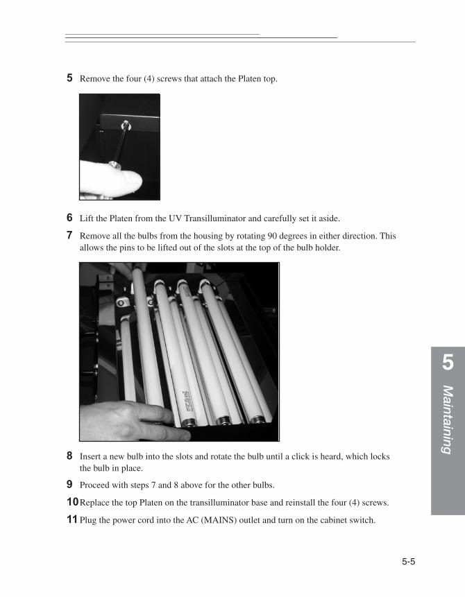
Maintaining
5
5 Remove the four (4) screws that attach the Platen top.
6 Lift the Platen from the UV Transilluminator and carefully set it aside.
7 Remove all the bulbs from the housing by rotating 90 degrees in either direction. This allows the pins to be lifted out of the slots at the top of the bulb holder.
8 Insert a new bulb into the slots and rotate the bulb until a click is heard, which locks the bulb in place.
9 Proceed with steps 7 and 8 above for the other bulbs.
10Replace the top Platen on the transilluminator base and reinstall the four (4) screws.
11 Plug the power cord into the AC (MAINS) outlet and turn on the cabinet switch.
5-5

5-6
Replacing the White Light Epi-Illumination Bulbs
Tools required:
✔ 2.5 mm Allen wrench
Replacement parts:
✔ GL2200 PRO White Light Bulb Kit (1)
1 Turn off the cabinet switch.
2 Remove the power cord from the AC (MAINS) outlet.
WARNING: The power cord is the primary disconnect device from the AC (MAINS) outlet. Always turn the switch the cabinet off and disconnect the unit from the AC (MAINS) outlet before performing any service.
3 Open the GL2200 PRO Imaging Cabinet door.
4 Remove the bottom screw on the side of the bulb housing and rotate the retaining plate 180° clockwise.
5 Slide the white diffuser cover towards the front of the cabinet to remove.
6 Push the red button while simultaneously rotating the bulb counter clockwise and lift out to remove it from the bulb holder.

Maintaining
5
7 Install a new bulb by pushing the base into the bulb holder until it snaps into place.
8 Reinstall the diffuser cover by sliding it back into the frame.
9 Rotate the retaining plate back into position.
10 Install the retaining screw on the side of the housing.
11 Repeat Steps 4 through 10 to replace the bulbs in the second light fixture.
12Plug the power cord into the AC (MAINS) outlet.
13Turn on the cabinet power switch.
5-7
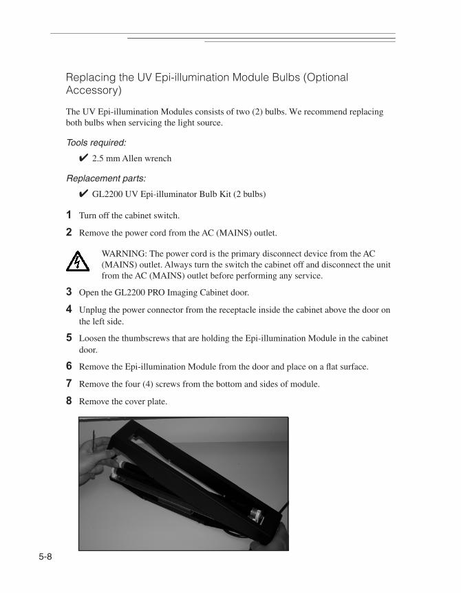
5-8
Replacing the UV Epi-illumination Module Bulbs (Optional Accessory)
The UV Epi-illumination Modules consists of two (2) bulbs. We recommend replacing both bulbs when servicing the light source.
Tools required:
✔ 2.5 mm Allen wrench
Replacement parts:
✔ GL2200 UV Epi-illuminator Bulb Kit (2 bulbs)
1 Turn off the cabinet switch.
2 Remove the power cord from the AC (MAINS) outlet.
WARNING: The power cord is the primary disconnect device from the AC (MAINS) outlet. Always turn the switch the cabinet off and disconnect the unit from the AC (MAINS) outlet before performing any service.
3 Open the GL2200 PRO Imaging Cabinet door.
4 Unplug the power connector from the receptacle inside the cabinet above the door on the left side.
5 Loosen the thumbscrews that are holding the Epi-illumination Module in the cabinet door.
6 Remove the Epi-illumination Module from the door and place on a flat surface.
7 Remove the four (4) screws from the bottom and sides of module.
8 Remove the cover plate.

Maintaining
5
9 Remove the bulb by rotating 90 degrees in either direction. This allows the pins to be lifted out of the slots at the top of the bulb holder.
10 Insert a new bulb into the slots and rotate the bulb until a click is heard, which locks the bulb in place.
11 Proceed with steps 9 and 10 above for the second bulb.
12Reinstall the cover plate with the retaining screws.
13Reinstall the module in the cabinet door (see Installing the UV Epi-illumination Module in Chapter 3: Installing Your System).
14Tighten the thumbscrews.
15Plug the power connector into the receptacle inside the GL2200 PRO Imaging Cabinet above the door on the left side.
16Close the door making sure that the door is not pinching the power cord when it is closed. If it is being pinched, unplug the cable and rotate the connector 360 degrees to eliminate any twist that is in the cable.
☞ NOTE: The UV Epi-illumination Module illuminates when UV Epi is selected in the GL2200 PRO Acquire window.
17Unplug the power connector from the receptacle inside the cabinet above the door on the left side.
18Plug the power cord into the AC (MAINS) outlet.
19Turn on the cabinet power switch.
FPO
5-9

5-10
Replacing the UV Transilluminator Platen
Tools required:
✔ No. 2 Phillips screwdriver
Replacement parts:
✔ GL2200 PRO UV Transilluminator Platen Kit
1 Turn off the cabinet power switch.
2 Remove the power cord from the AC (MAINS) outlet.
WARNING: The power cord is the primary disconnect device from the AC (MAINS) outlet. Always turn the Illumination Selector off and disconnect the unit from the AC (MAINS) outlet before performing any service.
3 Open the GL2200 PRO Imaging Cabinet door.
4 Pull the transilluminator drawer out far enough to allow access to the four (4) Phillips head screws on the sides of the Platen top.
5 Remove the four (4) screws that attach the Platen top.
6 Lift the Platen from the UV Transilluminator and carefully set it aside.
7 Position the new Platen on the transilluminator base and reinstall the four (4) screws.
8 Plug the power cord into the AC (MAINS) outlet.
9 Turn on the cabinet power switch.

Troub
leshoo
ting
6
Troubleshooting the SystemIn this chapter, common questions are addressed. The questions are divided into three sections: Instrument, Image, and Software. If you still have questions after reading this section and the corresponding information in the User’s Guide, contact Carestream Molecular Imaging Technical Support. Please have your serial number and any technical information available.
6-1

6-2
Technical Support
For technical support, contact Carestream Molecular Imaging Technical Support or your Carestream Molecular Imaging dealer. For up to date dealer information, visit our WEB site at mi.carestreamhealth.com. When contacting technical support, please have the following information available:
✔ The serial number of your GL2200 PRO located on the back of the unit.
✔ The serial number of your GL2200 PRO Camera—press Control and T buttons simultaneously when the GL2200 PRO Acquire window is displayed.
✔ The serial number and version number of your Carestream MI.
☞ NOTE: With the software running, select About MI under the Help menu (Windows) or select About MI under the Apple menu item (Macintosh).
✔ The type of computer you are using (make, model).
✔ Operating system software version.
☞ NOTE: Check your operating system version by right-clicking on the My Computer icon and then on Properties (Windows) or select About This Mac under the Apple menu item (Macintosh).
✔ The type of image you are capturing or analyzing.
✔ The problem you are having and what you were doing when the problem occurred. Please note the exact wording of any error messages, including any error numbers displayed.
Carestream Molecular Imaging Technical Support
Contact Carestream Molecular Imaging Technical Support by:
✔ Utilizing our World Wide Web support pages at:
mi.carestreamhealth.com
✔ Calling Carestream Molecular Imaging Technical Support at:
In US and Canada 877-747-4357 or world wide 203-786-5657, between the hours of 8:00 a.m. and 6:00 p.m. (Eastern Standard Time) Monday through Friday
✔ E-mailing Carestream Molecular Imaging Technical Support at:
✔ Faxing Carestream Molecular Imaging Technical Support at:
203-786-5656

Troub
leshoo
ting
6
Common Instrument ProblemsProblem Probable Cause Solution
Cannot access the camera capture system.
Camera/Computer Interface Cable is not properly connected.
Check the connections on the back of the GL2200 PRO and the computer.
The Camera/Computer Interface Cable Cable that came with the system was not used.
Make sure that the cables being used is the one you received with your GL2200 PRO.
No power to the system. Verify that the Line Cord is connected to the AC (MAINS) and that the power switch is in the ON Position. The green light on the front panel should be illuminated.
Wrong camera selected. Verify that you selected GL2200 PRO from the Digital Camera pop-up menu in Digital Camera submenu of the File menu.
UV Transilluminator lights are flickering.
Either the bulbs need replacement or a ballast problem.
Test whether the bulbs or the ballast needs replacement, replace the UV bulbs with similarly sized white light bulbs. If the bulbs flicker, the ballast needs changing. If the bulbs don’t flicker, the UV bulbs need replacement.
6-3

6-4
UV Transilluminator/ UV Epi lights are not operating.
No power. Check that the power cord on the back of the instrument is properly attached and that the outlet is supplying power.
Check that the main power switch on the back panel is set to the ON position.
Verify that the UV Epi-illumination Module is properly connected to the cabinet.
The cabinet door safety switch is not engaging.
Verify that the door is firmly closed and safety switch is engaged.
Either the bulbs need replacement or a ballast problem.
Test whether the bulbs or the ballast needs replacement, replace the UV bulbs with similarly sized white light bulbs. If the bulbs flicker, the ballast needs changing. If the bulbs don’t flicker, the UV bulbs need replacement.
Problem Probable Cause Solution
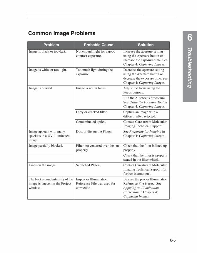
Troub
leshoo
ting
6
Common Image ProblemsProblem Probable Cause Solution
Image is black or too dark. Not enough light for a good contrast exposure.
Increase the aperture setting using the Aperture button or increase the exposure time. See Chapter 4: Capturing Images.
Image is white or too light. Too much light during the exposure.
Decrease the aperture setting using the Aperture button or decrease the exposure time. See Chapter 4: Capturing Images.
Image is blurred. Image is not in focus. Adjust the focus using the Focus buttons.
Run the Autofocus procedure See Using the Focusing Tool in Chapter 4: Capturing Images.
Dirty or cracked filter. Capture an image with a different filter selected.
Contaminated optics. Contact Carestream Molecular Imaging Technical Support.
Image appears with many speckles in a UV illuminated image.
Dust or dirt on the Platen. See Preparing for Imaging in Chapter 4: Capturing Images.
Image partially blocked. Filter not centered over the lens properly.
Check that the filter is lined up properly.
Check that the filter is properly seated in the filter wheel.
Lines on the image. Scratched Platen. Contact Carestream Molecular Imaging Technical Support for further instructions.
The background intensity of the image is uneven in the Project window.
Improper Illumination Reference File was used for correction.
Be sure the proper Illumination Reference File is used. See Applying an Illumination Correction in Chapter 4: Capturing Images.
6-5
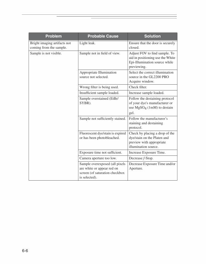
6-6
Bright imaging artifacts not coming from the sample.
Light leak. Ensure that the door is securely closed.
Sample is not visible. Sample not in field of view. Adjust FOV to find sample. To aid in positioning use the White Epi-Illumination source while previewing.
Appropriate Illumination source not selected.
Select the correct illumination source in the GL2200 PRO Acquire window.
Wrong filter is being used. Check filter.
Insufficient sample loaded. Increase sample loaded.
Sample overstained (EtBr/SYBR).
Follow the destaining protocol of your dye's manufacturer or use MgSO4 (1mM) to destain
gel.
Sample not sufficiently stained. Follow the manufacturer’s staining and destaining protocol.
Fluorescent dye/stain is expired or has been photobleached.
Check by placing a drop of the dye/stain on the Platen and preview with appropriate illumination source.
Exposure time not sufficient. Increase Exposure Time.
Camera aperture too low. Decrease f-Stop.
Sample overexposed (all pixels are white or appear red on screen (of saturation checkbox is selected).
Decrease Exposure Time and/or Aperture.
Problem Probable Cause Solution

Troub
leshoo
ting
6
Common Software ProblemsProblem Probable Cause Solution
My Macintosh computer is going to sleep mode.
System/Display sleep mode set incorrectly.
Under Control Panel/Energy Saver, set the sleep setting to Never.
My Windows computer is going to sleep mode.
System/Display sleep mode set incorrectly.
Click the Power Options icon from the Start menu and the Control Panel. Click Power Schemes tab and select Always On from the Power Schemes pop-up menu.The settings for Turn off monitor, Turn off hard disks, System standby and System hibernates functions become Never.
Error # 20005 The copy protection device is not found.
Connect the copy protection device and restart your computer.
Error # 12001 The copy protection device is configured for a newer version of MI.
You are using an older version of MI, you may want to use a newer version instead.
Error # 12002 The copy protection device is from an older version of MI.
Shut down your computer and attach the copy protection device that came with the newest version of Carestream MI. Restart your computer.
Error # 12002 A new copy protection device was expected, but not found.
Shut down your computer and attach the copy protection device that came with the newest version of Carestream MI. Restart your computer.
Error # 12003 The copy protection device was disabled during the upgrade process.
Shut down your computer and attach the upgrade copy protection device that came with the upgrade package. Restart your computer. Discard the disabled copy protection device.
Error #12004 Upgrading your MI requires both your existing and new copy protection devices.
Connect both your existing copy protection device and the upgrade copy protection device to your computer and restart the computer.
6-7

6-8

Warranty
Warranty
Warranty Time Period
Carestream Health, Inc. warrants the Carestream Gel Logic 2200 PRO Imaging System (GL2200 PRO) to be free from malfunctions and defects in both materials and workmanship for one year from the date of purchase. If a computer was purchased with the GL2200 PRO, it is covered under separate warranty provided by the computer manufacturer.
Days and Hours of Coverage
Arrangements for service through Carestream Molecular Imaging Technical Support can be made Monday through Friday 8:00 a.m. to 6:00 p.m. EST in the United States, except for locally observed holidays. Hours of coverage outside the United States may vary. Contact your local Carestream Molecular Imaging dealer for hours of coverage.
Warranty Repair Coverage
If the equipment does not function properly during the warranty period due to defects in either materials or workmanship, Carestream Health, Inc. will, at its option, either repair or replace the equipment without charge, subject to the conditions and limitations stated herein. Such repair service will include all labor as well as any necessary adjustments and/or replacement parts.
If replacement parts are used in making repairs, these parts may be remanufactured, or may contain remanufactured materials. If it is necessary to replace the entire system, it may be replaced with a remanufactured system.
Carestream Health, Inc. will also provide telephone assistance during the warranty period.
W-1

W
Limitations
WARRANTY SERVICE WILL NOT BE PROVIDED WITHOUT DATED PROOF OF PURCHASE. PLEASE RETURN THE WARRANTY REGISTRATION CARD WITHIN 30 DAYS OF PURCHASE.
THIS WARRANTY BECOMES NULL AND VOID IF YOU FAIL TO PACK YOUR INSTRUMENT IN A MANNER CONSISTENT WITH THE ORIGINAL PRODUCT PACKAGING AND DAMAGE OCCURS DURING PRODUCT SHIPMENT.
THIS WARRANTY DOES NOT COVER: CIRCUMSTANCES BEYOND CARESTRAM HEALTH'S CONTROL; SERVICE OR PARTS TO CORRECT PROBLEMS RESULTING FROM THE USE OF ATTACHMENTS, ACCESSORIES OR ALTERATIONS NOT MARKETED BY CARESTREAM HEALTH, INC.; SERVICE REQUIRED AS THE RESULT OF UNAUTHORIZED MODIFICATIONS OR SERVICE; MISUSE, ABUSE; FAILURE TO FOLLOW CARESTREAM HEALTH'S OPERATING, MAINTENANCE OR REPACKAGING INSTRUCTIONS; OR FAILURE TO USE ITEMS SUPPLIED BY CARESTREAM HEALTH, INC. (SUCH AS ADAPTERS AND CABLES).
CARESTREAM HEALTH, INC. MAKES NO OTHER WARRANTIES, EXPRESS, IMPLIED, OR OF MERCHANTABILITY OR FITNESS FOR A PARTICULAR PURPOSE FOR THIS EQUIPMENT OR SOFTWARE.
REPAIR OR REPLACEMENT WITHOUT CHARGE ARE CARESTREAM HEALTH’S ONLY OBLIGATION UNDER THIS WARRANTY. CARESTREAM HEALTH, INC. WILL NOT BE RESPONSIBLE FOR ANY SPECIAL, CONSEQUENTIAL OR INCIDENTAL DAMAGES RESULTING FROM THE PURCHASE, USE, OR IMPROPER FUNCTIONING OF THIS EQUIPMENT REGARDLESS OF THE CAUSE. SUCH DAMAGES FOR WHICH CARESTREAM HEALTH, INC. WILL NOT BE RESPONSIBLE INCLUDE, BUT ARE NOT LIMITED TO, LOSS OF REVENUE OR PROFIT, DOWNTIME COSTS, LOSS OF USE OF THE EQUIPMENT, COST OF ANY SUBSTITUTE EQUIPMENT, FACILITIES OR SERVICES, OR CLAIMS OF YOUR CUSTOMERS FOR SUCH DAMAGES.
Depending on your geographical location, some limitations and exclusions may not apply.
-2
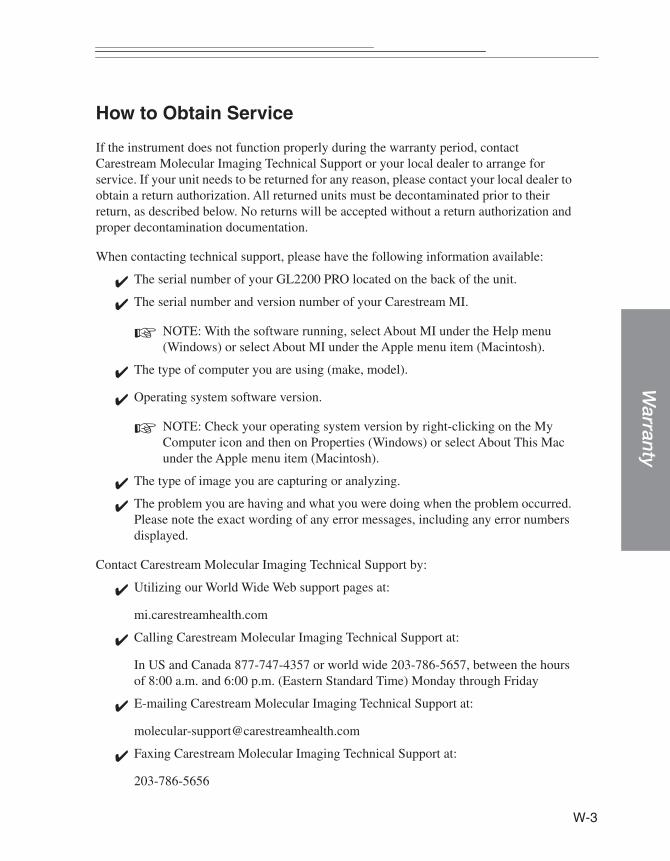
3
Warranty
W-
How to Obtain Service
If the instrument does not function properly during the warranty period, contact Carestream Molecular Imaging Technical Support or your local dealer to arrange for service. If your unit needs to be returned for any reason, please contact your local dealer to obtain a return authorization. All returned units must be decontaminated prior to their return, as described below. No returns will be accepted without a return authorization and proper decontamination documentation.
When contacting technical support, please have the following information available:
✔ The serial number of your GL2200 PRO located on the back of the unit.
✔ The serial number and version number of your Carestream MI.
☞ NOTE: With the software running, select About MI under the Help menu (Windows) or select About MI under the Apple menu item (Macintosh).
✔ The type of computer you are using (make, model).
✔ Operating system software version.
☞ NOTE: Check your operating system version by right-clicking on the My Computer icon and then on Properties (Windows) or select About This Mac under the Apple menu item (Macintosh).
✔ The type of image you are capturing or analyzing.
✔ The problem you are having and what you were doing when the problem occurred. Please note the exact wording of any error messages, including any error numbers displayed.
Contact Carestream Molecular Imaging Technical Support by:
✔ Utilizing our World Wide Web support pages at:
mi.carestreamhealth.com
✔ Calling Carestream Molecular Imaging Technical Support at:
In US and Canada 877-747-4357 or world wide 203-786-5657, between the hours of 8:00 a.m. and 6:00 p.m. (Eastern Standard Time) Monday through Friday
✔ E-mailing Carestream Molecular Imaging Technical Support at:
✔ Faxing Carestream Molecular Imaging Technical Support at:
203-786-5656
W
General Instructions for Cleaning and Decontamination For Return of the GL2200 PRO
All returned material must be cleaned and decontaminated prior to shipping. To meet Federal and State Regulatory and Safety standards, please follow the decontamination procedure given here if radioactive materials are used with this product or are used in the vicinity of where this apparatus has been used or stored.
General Cleaning Procedure
For materials not contaminated with biological or radiological substances, components may be gently washed using water or an ammonia based spray cleaner using soft lint-free cloth or lens paper.
WARNING:Do not expose Platen to strong chemical solvents such as ketones and hexanes. This may permanently damage the Platen and will void your warranty.
Radiological Decontamination Procedure
WARNING: We cannot accept return of products which are contaminated with any radioactivity.
For beta emitting isotopes such as 32P, use a GM-type radioactivity meter calibrated in counts per minute (CPM) to determine the background readings for your work area. Wearing latex gloves, survey the unit to be returned with the GM meter. If any part of the unit is found to show readings higher than background, wash the area using Count Off™ (PerkinElmer Life Sciences) or another similar commercially available detergent and paper towels. If none are available, a Formula 409™-like solution or a mild detergent will do. As you clean, discard liquid and solid waste (gloves and paper towels) according to your local and institutional regulations for radioactive material disposal. Continue washing until the GM meter reading for the contaminated area(s) is equal to or below background.
-4

Warranty
To decontaminate units where a GM-meter is not useful for detection, such as with 3H or 35S, it will be necessary to perform swipes of the unit and detect using a scintillation counter. The unit should be dry. Wipe surfaces with dry paper circles (these are commercially available or you can make your own). Areas can be charted, so that individual swipes can be done on different surfaces to better isolate areas of contamination. These swipes are then placed into individual scintillation vials with an appropriate fluor and then analyzed on a properly programmed scintillation counter. If contamination above 200 disintegrations per minute dpm/200 cm2 (dpm = CPM/efficiency) is found, wash the area as described above for beta emitting isotope decontamination. After cleaning the area, swipe it a second time to determine the amount of contamination remaining. If the area still has a greater than 200 dpm/cm2, continue the cycle of swipes and washing until you achieve a reading of less than 200 dpm/cm.2
Once the unit has been determined to be radiation free (< 200 dpm/cm2), remove all the hazardous and radioactive labels from the unit. If the labels cannot be removed, deface them. Failure to do so may result in significant delay or a refusal of repair.
If your unit has unremovable decontamination (detectable with a GM-meter and not with paper swipes, or detectable with paper swipes but after continued washing the dpm/cm2 remains constant above 200) of a short half life isotope such as 32P, the unit may be stored for 10 half lives of isotopic decay and the decontamination procedure repeated.
☞ NOTE: Units contaminated with unremovable, long half life isotopes may not be returned.
W-5
W
Repackaging the GL2200 PRO
Inappropriate packing will void the GL2200 PRO warranty. Follow these directions when packing the GL2200 PRO for shipment.
1 Decontaminate the GL2200 PRO as described above.
2 Remove the power cord and Camera/Computer Cables from the rear of the GL2200 PRO.
3 Remove the Filters, optional White Light Transilluminator and/or UV Epi-illumination Modules from the imaging cabinet.
4 Unscrew and remove the Camera Assembly from the imaging cabinet.
5 Package the Camera Assembly in foam padding.
6 Place the components in their original plastic wrapping.
7 Repack the GL2200 PRO components in their original boxes. If you have discarded the original packing material, call Carestream Molecular Imaging Technical Support to arrange for delivery of new packing material.
-6

Warranty
Regulatory Information
This equipment has been tested and found to comply with the limits for a Class A digital device pursuant to Part 15 of the FCC rules. These limits are designed to provide reasonable protection against harmful interference when the equipment is operated in a commercial environment. This equipment generates, uses, and can radiate radio frequency energy and, if not installed and used in accordance with the instruction manual, may cause harmful interference to radio communications. Operation of this equipment in a residential area is likely to cause harmful interference in which case the user will be required to correct the interference at his own expense.
Any changes or modifications not expressed by the party responsible for compliance could void the user’s authority to operate the equipment. Where shielded interface cables have been provided with the product or specified additional components or accessories elsewhere defined to be used with the installation of the product, they must be used in order to ensure compliance with FCC regulation.
Disposal of these materials may be regulated due to environmental considerations. For disposal or recycling information, please contact your local authorities, or in the U.S.A., contact the Electronics Industry Alliance web site at www.eiae.org.
The sound pressure level (LA) is less than 70 dB.
This Class A digital apparatus meets all requirement of the Canadian Interference-Causing Equipment Regulations.
Cet appareil numérique de la classe A respecte toutes les exigences du Réglement sur le matériel brouilleur du Canada.
For Use in European Union
WARNING
This is a class A product. In a domestic environment this product may cause radio interference in which case the user may be required to take adequate measures.
W-7
W
In the European Union, this symbol indicates that when the last user wishes to discard this product, it must be sent to appropriate facilities for recovery and recycling. Contact your local representative or refer to http://recycle.carestreamhealth.com for additional information on the collection and recovery programs available for this product.
For Use in Japan
For Use in Taiwan
-8
Glo
ssary
Glossary
Analog Signal—A signal that is continuous and uninterrupted. Variations in voltage correspond to variations in brightness. This differs from digital, where a signal is represented in discrete steps of digital value (1's, 0's).
Analog to Digital (A/D) Converter—An integrated circuit that transforms an analog (voltage level) to a binary (or digital) value. The GL2200 PRO camera converts the analog signal into a digital signal using an A/D converter.
Aperture—The opening within a lens that limits light passage, usually adjustable and referred to as the f-stop.
Autoradiography—A method of capturing radioactive signals by contact-exposure of film to a flat sample consisting of radioactive objects or labeled molecules.
Binning—The process by which adjacent CCD signal values are added together and then each pixel value is replaced with the new added value. For example, if two adjacent pixels have an intensity value of 100 and 150, when binning has been applied, both pixels will be assigned a value of 250. Binning can be applied on X and/or Y axis of an image. While binning decreases the resolution of the image, it increases the sensitivity of the signal.
Bit (Binary Digit)—The smallest amount (unit) of information, measured on a binary scale (integer exponents of 2), where combinations of 0's and 1's are used to code information. See Bit Depth. Eight bits of information is called one byte.
Bit Depth (Bits-Per-Pixel or Pixel Depth)—The number of intensity values that can be assigned to each pixel. Images usually fall between 8 and 24 bits. The GL2200 PRO camera produces a 16-bit image in the single capture mode or n-bit in the multiple capture mode. A 16-bit image has 65,536 gray levels.
Black Point—Corresponds to an intensity value in the image that represents pure black in the screen image. The black point can be adjusted using the histogram sliders to help visualize different features in the image. Features with intensity values below the black point can no longer be seen in the screen image. Adjustments to the black point alter the screen image and do not alter the data that is transferred to Carestream Molecular Imaging Software for analysis.
Glossary-1
G
Blooming—If the CCD is overexposed, the CCD pixels do not have the capacity to hold the charge and will “bloom” or spill into the adjacent pixel. Blooming distorts the image. However, excessive signal may often be associated with the property of the object and not the blooming of the CCD.
Blot—A methodology in which molecules/particles of interest are transferred and affixed to a solid support (membrane), usually for the sake of detection and imaging. A liquid sample may be applied to a membrane as a spot, dot, or slot (band), defining a formatted sample array as a Dot or Slot Blot. Electrophoresis gels used to length-resolve DNA, RNA or protein molecules may be similarly transferred to membranes by mechanical extrusion or electrophoresis; such blots are respectively called Southern, Northern, or Western Blots.
Brightness—A relative measure of light associated with a pixel representing its gray level from black and white, through intermediate levels of gray. Perceived brightness increases from dark to bright, or black to white through intermediate levels of gray. However, the convention of quantitative imaging is quite the opposite, wherein the gray scale is increased from white to black.
CCD (Charged-Coupled Device)—An electronic sensor used for imaging light. A silicon crystal, etched to produce micro-electronic circuitry, for the purpose of transforming a real image into an electronic image. A photon impinging upon the silicon is converted to an electron (a negative charge, stable in the crystal matrix), that may be subsequently managed (collected and transported) by the circuitry. The CCD in the GL2200 PRO has 1708 x 1280 = 2,186,240 imaging elements (pixels) defined by etchings.
Chemifluorescence—Chemically mediated production of a fluorochrome. Fluorescent molecules may be produced by the chemical (enzymatic) conversion of a non-fluorescent molecule (substrate), upon excitation (laser or UV illumination).
Chemiluminescence—Chemically mediated production of light. Luminescence or light emission may be produced by a chemical reaction or an enzyme operating on a substrate.
Contrast—The contrast of an image represents the perceived differences in intensity between dark and light areas within the image. A low contrast image contains gray levels that are similar in visual intensity, whereas a high contrast image contains extreme differences in visual intensity.
Cosmic Ray—Its a random event in nature that generates a photon which exposes a pixel on a CCD.
lossary-2
Glo
ssary
Dark Current Noise—Electronic noise inherent to the CCD sensor and circuitry, which is increased with extended exposure time. Cooling the CCD helps reduce dark current noise. The GL2200 PRO camera is capable of about 1 hour exposure times with only a doubling of noise.
Digital Camera—A camera that uses an electronic sensor to record an image in a digital binary format.
Dynamic Range—The maximum range of significant digits over which system hardware performs electronic imaging, usually expressed as a signal-to-noise ratio. The GL2200 PRO camera provides a 16-bit (65,536 gray levels) signal range for single captures. These single captures can be accumulated by addition in software into a n-bit file. With a noise level of approximately 2.4 levels for a single capture, the maximum dynamic range of signal-to-noise is about 1,700 for single captures and about 6,200 for accumulated images.
Electrophoresis—Separation of molecules on the basis of charge and size.
Floating Point—A means of representing a signal as real numbers (fractions or decimals). Floating point calculations are important in maintaining the accuracy of analysis data. The Carestream Molecular Imaging Software uses floating point numbers.
f-stop—The ratio of focal length to the aperture diameter in the lens.
Gamma—A mathematical transformation function that can be used to improve image appearance by decreasing or increasing the contrast of an element of interest in an image. Adjusting the gamma of an image disproportionately skews the gray level distribution, higher gamma values lighten the image and lower gamma values darken the image. Adjusting the gamma does not alter the image data file and is only used to enhance the viewing of the image.
Gel—A separation matrix which is typically agarose or acrylamide and is used for electrophoresis.
Gray Level—The digital signal assigned to a pixel associated with a level of light (from black to white). For example, an 8-bit and a 16-bit system includes gray level values between 0–255 and 0–65,535, respectively.
Histogram—The frequency of the distribution of pixels over the range of signals within an image. The horizontal axis represents the gray level and the vertical axis represents the number of pixels.
Glossary-3
Gl
Image Accumulation—The addition of multiple exposures (also referred to as frame captures). The data from all the summed images are used to generate the final image for analysis.
Image Compression—A computational operation upon image data that results in a reduction of data storage volume. Usually results in some loss of image data.
Interpolation—A numerical estimate of a value within a range of empirical data, based on the mathematical trend of data. Contrasts with extrapolation, in which a value outside the range of data is estimated.
Noise—Random and/or persistent deviations in signal. In a digital camera the CCD has noise associated with the collection, reading and amplification of the signal that may affect image quality. The GL2200 PRO camera reduces noise by cooling the CCD using thermoelectrical cooling.
Photon—The smallest unit of light, or any electromagnetic radiation. Characterized by wavelength.
Pixel—The fundamental element in a digital image. In a digital camera, the pixels represents the light sensitive elements on the CCD.
Read Noise—Electronic distortions in signal introduced when converting the analog signal to a digital signal.
Resolution—The capability to distinguish between objects of interest. It is customary, when describing the characteristics of a digital imaging device or image, to describe the resolution by specifying the number of pixels it captures in the horizontal by vertical direction.
Saturation—The limitation of signal imposed by either the CCD or the digital scale in which the signal is being represented. If the signal becomes too large the individual pixels on the CCD will be filled and no additional signal can be detected.
Thermoelectrical Cooling—A system that uses electron flow through semiconductors to generate temperature differences. The CCD is mounted on the cool side and the heat is dissipated by cooling fans. GL2200 PRO uses a thermoelectrical cooling system to reduce image noise generated by the heat from within the camera’s CCD.
TIFF—(Tagged Image File Format) is an industry standard file format for storing images. Images from Carestream Molecular Imaging Software can be saved in TIFF format for use with other computer programs.
ossary-4

Glo
ssary
Transmission—Mode of image capture, usually absorbance, in which light passes through the illuminated object.
Vignetting—An imaging artifact that is associated with the limitation of the lens. Vignetting generally appears as signal reduction around the edges of the image.
White Light—Light that is in the visual part (400–700 nm) of the spectrum (daylight, regular light bulbs).
White Point—Corresponds to an intensity value in the image that represents pure white in the screen image. The white point can be adjusted using the histogram sliders to help visualize different features in the image. Features with intensity values above the white point can no longer be seen in the screen image. Adjustments to the white point alter the screen image and do not alter the data that will be transferred to Carestream Molecular Imaging Software for analysis.
X and/or Y Binning—See Binning.
Glossary-5

Gl
ossary-6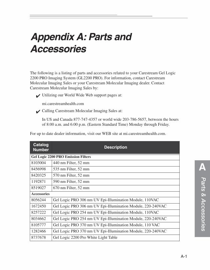
Parts &
Accesso
ries
A
Appendix A: Parts and Accessories
The following is a listing of parts and accessories related to your Carestream Gel Logic 2200 PRO Imaging System (GL2200 PRO). For information, contact Carestream Molecular Imaging Sales or your Carestream Molecular Imaging dealer. Contact Carestream Molecular Imaging Sales by:
✔ Utilizing our World Wide Web support pages at:
mi.carestreamhealth.com
✔ Calling Carestream Molecular Imaging Sales at:
In US and Canada 877-747-4357 or world wide 203-786-5657, between the hours of 8:00 a.m. and 6:00 p.m. (Eastern Standard Time) Monday through Friday.
For up to date dealer information, visit our WEB site at mi.carestreamhealth.com.
Catalog Number
Description
Gel Logic 2200 PRO Emission Filters
8103004 440 nm Filter, 52 mm
8456998 535 nm Filter, 52 mm
8420325 570 nm Filter, 52 mm
1192871 590 nm Filter, 52 mm
8519027 670 nm Filter, 52 mm
Accessories
8056244 Gel Logic PRO 306 nm UV Epi-Illumination Module, 110VAC
1672450 Gel Logic PRO 306 nm UV Epi-Illumination Module, 220-240VAC
8257222 Gel Logic PRO 254 nm UV Epi-Illumination Module, 110VAC
8034662 Gel Logic PRO 254 nm UV Epi-Illumination Module, 220-240VAC
8105777 Gel Logic PRO 370 nm UV Epi-Illumination Module, 110 VAC
1282466 Gel Logic PRO 370 nm UV Epi-Illumination Module, 220-240VAC
8737678 Gel Logic 2200 Pro White Light Table
A-1

A-
2Accessories, continued
1661669 Gel Logic 2200 Pro UV Shield
8406761 Gel Logic Gel Tray Accessory
1941442 Gel Logic Fluorescent Ruler
1411701 Gel Logic Field Flattening Screen
1693803 Mobile WorkStation, 4 foot
Computer & Printing Accessories
1903426 Desktop PC w/17” Flat Panel Monitor
8683336 Desktop Macintosh w/ 20” Flat Panel Monitor
1296409 Sony UP-D897 Thermal Printer
8650582 High Density Glossy Thermal Black and White Paper
User’s Guides
8848137 Gel Logic 2200 PRO User's Guide - English
1865476 Gel Logic 2200 PRO User's Guide - French
8701419 Gel Logic 2200 PRO User's Guide - German
Software Upgrades
8177446 Molecular Imaging Software Standard 5.X to Network Upgrade
1537893 Molecular Imaging Software Standard 5.X to Regulatory Upgrade
1274596 Molecular Imaging Network Licenses, 5.X
Service Contracts
1624923 Gel Logic 2200 On-Site Premium Service Contract, 1 year
1892884 Gel Logic 2200 On-Site Basic Service Contract, 1 year
8903601 Gel Logic 2200 Depot Service Plan, 1 year
1091958 Gel Logic 2200 Preventative Maintenance Service Plan, 1 year
Replacement Parts
1861848 Gel Logic PRO Epi White Light Bulb Kit(1/pk)
1920362 Gel Logic 306 nm UV Transillumination Bulb Kit (4/pk)
8295727 Gel Logic 365 nm UV Transillumination Bulb Kit (4/pk)
1125632 Gel Logic PRO Platen Replacement Kit
8480899 Gel Logic PRO Filter Tool
1209964 Gel Logic PRO Leveling Feet (4/pk)
Gel Logic PRO Ethernet Communication Cable
Catalog Number
Description
Index
Index
A
Acquire Software installation 2-6—2-19, 3-3—3-12launching 3-13—3-19, 4-2— 4-3Preferences 2-16—2-19windows 2-6—2-19, 4-2—4-14
Acquire window 2-7—2-20, 4-2—4.3, 4-8—4-16
Buttons section 2-6, 2-13Capture section 2-6, 2-9—2-10Emission Filter section 2-2, 2-6, 2-17,
3-30—3-31, 4-4Exposure section 2-6, 2-11—2-12Illumination section 2-6, 2-14, 4-5—
4-6Lens section 2-6, 2-13Preferences section 2-6, 2-16—2-19Preview 2-8
Annotations bar 2-6, 2-10, 4-13Aperture 2-13, 4-7
C
Cabinet, Imaginginstallation 3-20—3-33overview2-2—2-5
Cable Connector, Camera 2-2—2-3, 3-21, 3-22
camera about 1-1, 2-2—2-5
computer interface cable 2-2—2-3, 3-21, 3-22
installation 3-20—3-22Camera Cable Connector 2-2—2-3, 3-21,
3-22Capture
Annotation bar 4-13Custom settings 2-16—2-19, 4-9—4-
10Focusing Tool 4-11Illumination Reference 4-12images 4-1—4-14Launching software 4-2Preparing 4-4—4-5Previewing 4-5—4-8
Charged-Coupled-Device (CCD) 1-1, 2-2, 3-1
cleaning Cabinet 5-2Epi-illumination pads 5-3Filters 5-3
conventions, user’s guide 1-2Coomasse Blue 3-31, 4-4copy protection device 3-3, 3-6, 3-9, 3-11correction, illumination 2-14, 4-12Custom Capture settings 2-16—2-19, 4-
9—4-10Ddeleting setting 4-10digital camera 2-2—2-3
I
selecting 2-6, 3-28—3-29, 4-2decontamination W4—W-5
E
electrical Requirements 2-2Emission filters 2-2, 2-17, 3-30—3-31, 4-4environmental Requirements 2-2epi-illumination
installing 3-20—3-22, 3-25—3-26,overview 2-3—2-4, 2-14, 4-4using 4-5—4-8
ethidium bromide 3-31, 4-4Exposure 2-6, 2-11—2-12, 4-5—4-8
Multiple 2-11—2-12, 4-8Single 2-11—2-12, 4-7Standard 2-11—2-12, 4-7Time Lapse 2-11—2-12, 4-8
F
Filecapture 1-1, 2-1Illumination Reference 2-6, 2-14, 4-
12filter
440 nm2-2, 2-17, 3-30—3-31, 4-4535 nm 2-2, 2-17, 3-30—3-31, 4-4570 nm 2-2, 2-17, 3-30—3-31, 4-4670 nm 2-2, 2-17, 3-30—3-31, 4-4applying2-17, 3-30—3-31, 4-4choosing 4-4popup menu 2-2, 2-17, 3-30—3-31, 4-
4wheel 2-2, 2-17, 3-30—3-31, 4-4
Focusing tool 4-11
H
Hardware, GL2200 PROelectrical requirements 3-2
environmental requirements 3-2overview 2-2—2-5setup 3-20—3-31space requirements 3-2
I
IEEE 1394 portcamera cable connector 2-2—2-3, 3-
21, 3-22Illumination
choosing 2-14, 4-5—4-6Reference File 2-6, 2-14, 4-12UV Epi 2-14, 4-5—4-6UV Trans 2-14, 4-5—4-6White Light Epi 2-4—2-5, 4-6
Imagearea 2-3, 4-4—4-7capture 4-1—4-14illumination correction 2-6, 2-14, 4-
12orientation 2-16—2-17Preview 2-16—2-19saturation 2-11—2-12, 2-19, 4-6—4-7
Imaging Cabinetabout 2-2—2-5setting up 3-20—3-33
InstallationCarestream Molecular Imaging
Software 3-3—3-19hardware 3-20—3-33UV Transilluminator 3-20—3-21UV Epi-Illumination Light 3-25—3-
26UV Safety Shield 3-27White Light Transilluminator 3-20—
3-21
II

Index
L
Lens 2-13Aperture 2-13, 4-7Focusing 2-13, 4-7, 4-11FOV 2-13, 4-7
Launching Carestream MI Software 2-6, 3-13—3-15, 3-16—3-22, 4-2
M
Macintosh Requirements 1-5Software installation 3-8—3-12
maintenance 5-1—5-10Molecular Imaging Software, Carestream
installation 3-3—3-12launching2-6, 3-13—3-15, 3-16—3-
22, 4-2Macintosh install 3-8—3-12Preferences 2-16—2-19Package contents 1-4System requirements 1-5Windows 3-3—3-7
multiple exposures 2-11—2-12, 4-8
P
Package Contents 1-4Preferences
image capture 2-16—2-19Preview 2-6, 2-16—2-19, 4-5—4-8
Q
Quick Print 2-6, 2-13
R
reference file, applying 2-6, 2-14, 4-12registering 1-7regulatory information W-6repacking W-5
repairing 5-4—5-10epi white light bulbs 5-6—5-7epi-UV light bulbs 5-8—5-9UV transilluminator 5-4—5-5UV Transilluminator Platen 5-10
requirementselectrical 3-2environmental 3-2space 3-2system 1-5
S
sampleorienting 2-16—2-17
saturation 2-11—2-12, 2-19, 4-6—4-7Saving settings 2-9—2-10, 2-16—2-19, 4-
9—4-10single exposure 2-11—2-12, 4-7software
installation 3-3—3-12launching2-6, 3-13—3-15, 3-16—3-
22, 4-2Macintosh install 3-8—3-12Preferences 2-16—2-19Package contents 1-4System requirements 1-5Windows 3-3—3-7
space requirements 2-2standard capture 2-11—2-12, 4-7Stop Preview button 2-6, 2-16—2-19, 4-
5—4-8SYBR Green 3-31, 4-4SYBR Gold 3-31, 4-4SYPRO Orange 3-31, 4-4System, GL2200 PRO
components 1-4installation 3-1—3-33maintaining 5-1—5-8overview 1-1, 2-1—2-19registering 1-7
III

regulatory information W-6repacking W-5repairing 5-4—5-8requirements 1-5
T
Technical Support 1-6, 6-2, W-1, W-3Time lapse exposure 2-11—2-12, 4-8troubleshooting 6-1—6-8
U
uninstalling software3-3—3-4, 3-9Updating settings 2-9—2-10, 2-16—2-19,
4-10User name option 2-9—2-10, 2-16—2-19,
4-10User's Guide
about the 1-2Carestream MI 1-2conventions 1-2navigating 1-3
User section 2-9—2-10, 2-16—2-19, 4-10UV Transilluminator 3-20—3-21UV Epi-Illumination Light 3-25—3-26UV Safety Shield 3-27
use of 4-14
W
warranty W1—W-5coverage W-1decontamination W-4—W-5limitations W-2registration 1-7regulatory W-6service W-3time period W-1
white light epi-illumination 2-4—2-5, 4-6white light transillumination 2-4—2-5, 4-6Windows
requirements 1-5software installation 3-3—3-7
IV