Embed Size (px)
Citation preview
Faraday DiscussionsCite this: Faraday Discuss., 2016, 192, 9
PAPER
Ope
n A
cces
s A
rtic
le. P
ublis
hed
on 2
9 Ju
ne 2
016.
Dow
nloa
ded
on 1
2/20
/202
1 7:
20:0
8 PM
. T
his
artic
le is
lice
nsed
und
er a
Cre
ativ
e C
omm
ons
Attr
ibut
ion
3.0
Unp
orte
d L
icen
ce.
View Article OnlineView Journal | View Issue
Carbon Capture and Storage: introductorylecture
Berend Smitab
Received 18th June 2016, Accepted 29th June 2016
DOI: 10.1039/c6fd00148c
Carbon Capture and Storage (CCS) is the only available technology that allows us to
significantly reduce our CO2 emissions while keeping up with the ever-increasing global
energy demand. Research in CCS focuses on reducing the costs of carbon capture and
increasing our knowledge of geological storage to ensure the safe and permanent
storage of CO2. This brief review will discuss progress in different capture and storage
technologies.
Introduction
Why do we need a Faraday Discussion on carbon capture and storage? If wesimply leave all carbon in the ground there is no need to develop new technologiesto capture CO2 from ue gasses and/or to rene our knowledge on how topermanently store CO2 in geological formations. Indeed, there is little doubt thatin the long term we will have developed technologies to completely decarbonizeour energy production. There is also little doubt that 80% of all of tomorrow’senergy production will still be based on fossil fuels. In fact, most energyproduction scenarios assume that the relative importance of fossil fuels willdecrease in the coming years. However, as our total energy consumption isexpected to increase faster than renewable energies can grow, these scenarios alsopredict that in absolute terms the total fossil fuel production will continue toincrease.1
Carbon Capture and Storage (CCS) is aimed at making this transition towardsdecarbonized energy production as smooth as possible. As we will see in the restof these Discussions, we do have the technology to capture and store signicantamounts of emitted CO2. However, the costs associated with such a reduction ofCO2 emissions are large. These Discussions show that we are generating manyoptions to reduce these costs. These costs, however, will never be zero and societywill have to pay more for energy. At present one can emit CO2 without any costs. It
aLaboratory of Molecular Simulation, Institut des Sciences et Ingenierie Chimiques, Valais, Ecole Polytechnique
Federale de Lausanne (EPFL), Rue de l'Industrie 17, CH-1951 Sion, Switzerland. E-mail: [email protected] of Chemical and Biomolecular Engineering, University of California, Berkeley, CA 94720-1462,
USA
This journal is © The Royal Society of Chemistry 2016 Faraday Discuss., 2016, 192, 9–25 | 9
Faraday Discussions PaperO
pen
Acc
ess
Art
icle
. Pub
lishe
d on
29
June
201
6. D
ownl
oade
d on
12/
20/2
021
7:20
:08
PM.
Thi
s ar
ticle
is li
cens
ed u
nder
a C
reat
ive
Com
mon
s A
ttrib
utio
n 3.
0 U
npor
ted
Lic
ence
.View Article Online
is only if we, as a society, put a price on emitting carbon or regulate the maximumallowed global CO2 emission, that the technologies described here will be of anyuse.2
The ideas underlying carbon capture and storage are simple (see Fig. 1).3–6 Therst step is to separate CO2 from a stationary source, which can, for example, bea coal or gas red power plant or a cement factory. The next step is to transportCO2 through a pipeline, and subsequently store CO2 in a geological formation.There are no fundamental technological barriers for each of these three steps, andhence to implement large-scale CCS.
A carbon-capture unit can be based on the many years of experience we havewith sweetening natural gas. Most natural gas contains signicant amounts ofCO2, which needs to be removed before commercial use. The current technologyof gas sweetening is based on scrubbing with amine solutions, which wasdeveloped in 1930 by Bottoms.7 Amine scrubbing can also be used to capturecarbon from ue gasses.8 For many years, oil companies have used CO2 toenhance the recovery of oil. Enhanced oil recovery involves the transport andinjection of CO2 in those geological formations where oil is produced. Thistechnology can be adopted to inject CO2 into geological formations for permanentstorage.
A question one oen poses is whether we should not recycle the CO2 that isproduced from a power plant.9 CO2 is a waste product, so why does the title of thisarticle not include recycling or re-use of CO2? First of all, CO2 is used in severalapplications. For example, most CO2 for enhanced oil recovery is obtained fromgeological formations; using CO2 from anthropogenic sources is simply moreexpensive. Of course, one would like that all the CO2 that is at present usedcommercially should come from anthropogenic sources. However, as our CO2
production from power plants alone is orders of magnitude larger than what wecan use, using anthropogenic CO2 for these applications will be important todevelop the technologies, but will have a minor effect on emissions. We simplyproduce so much CO2 that we will saturate any conceivable market if we convertCO2 into useful chemicals.10
Fig. 1 Schematic drawing of a carbon capture and storage project (figure adopted fromSmit et al.3).
10 | Faraday Discuss., 2016, 192, 9–25 This journal is © The Royal Society of Chemistry 2016
Paper Faraday DiscussionsO
pen
Acc
ess
Art
icle
. Pub
lishe
d on
29
June
201
6. D
ownl
oade
d on
12/
20/2
021
7:20
:08
PM.
Thi
s ar
ticle
is li
cens
ed u
nder
a C
reat
ive
Com
mon
s A
ttrib
utio
n 3.
0 U
npor
ted
Lic
ence
.View Article Online
There are only two products that are produced on the scale of CO2: water andfuels. One could therefore envision closing the combustion cycle and convertingCO2 back into a fuel. This scheme will only reduce CO2 emissions if we havea source of renewable, non-CO2 emitting, energy. However, given such a source ofrenewable energy there might be little need to use fossil fuels in the rst place.One of the issues with renewable energy is its intermittency, which requiresadditional technologies to store energy. If we produce electricity from solar energyduring the day, we rely on storage for the night, or wind energy might be availablein excess during the winter, but not enough during the summer. Fossil fuels haveexcellent energy storage capacity and one can envision using an excess ofrenewable energy to convert CO2 into a synthetic fuel for storage or transportationfuels. But, in the case of transportation fuels, only if the CO2 is coming directlyfrom the air can one truly close the carbon loop.
It is also important to realize that a fraction of the fossil fuels are used by thechemical industry as a feedstock for chemicals, and ideally one would also like toreplace these fossil fuels with CO2 as the source of carbon. Therefore utilization ofCO2 in the context of decarbonizing the chemical industry is an important topic ofresearch.11
Given the enormous volumes of CO2 that fossil fuel power plants generate, theonly viable option to signicantly reduce CO2 emissions is to carry out large-scaleCCS. At present CCS is only possible for stationary sources, which amounts toapproximately 50% of all CO2 emissions (see Fig. 2). That the technologies to carryout large-scale CCS exist does not imply that no further research is needed. On thecapture side one has to realize that the separation of CO2 from ue gasses ofa power plant costs energy and requires additional investments, which increasethe price of electricity signicantly. In addition, large-scale CO2 storage raisesquestions on how we can guarantee the long-term safety of the injected CO2.These two issues, the concern of the public about the cost of capture and thesafety of geologically stored CO2, are also the driving force of most of the researchunderlying this Faraday Discussions.
This Faraday Discussions brings together researchers from several differentelds. In this Introductory Lecture the context is given on how these differentcontributions will help us in addressing the main challenges in CCS. Thesecontributions range from pilot-plant studies and cost calculations, toobtaining a detailed fundamental understanding of the materials that areinvolved.
Fig. 2 (Left) Fraction of the total CO2 emission from stationary sources and (right) CO2
from the different stationary sources (figure adopted from Smit et al.3).
This journal is © The Royal Society of Chemistry 2016 Faraday Discuss., 2016, 192, 9–25 | 11
Faraday Discussions PaperO
pen
Acc
ess
Art
icle
. Pub
lishe
d on
29
June
201
6. D
ownl
oade
d on
12/
20/2
021
7:20
:08
PM.
Thi
s ar
ticle
is li
cens
ed u
nder
a C
reat
ive
Com
mon
s A
ttrib
utio
n 3.
0 U
npor
ted
Lic
ence
.View Article Online
Carbon capture
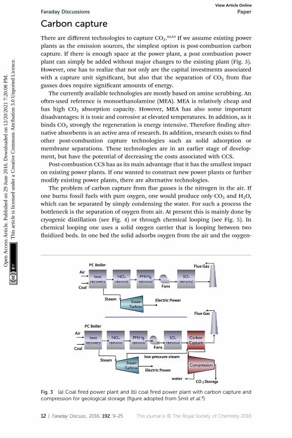
There are different technologies to capture CO2.12,13 If we assume existing powerplants as the emission sources, the simplest option is post-combustion carboncapture. If there is enough space at the power plant, a post combustion powerplant can simply be added without major changes to the existing plant (Fig. 3).However, one has to realize that not only are the capital investments associatedwith a capture unit signicant, but also that the separation of CO2 from uegasses does require signicant amounts of energy.
The currently available technologies are mostly based on amine scrubbing. Anoen-used reference is monoethanolamine (MEA). MEA is relatively cheap andhas high CO2 absorption capacity. However, MEA has also some importantdisadvantages: it is toxic and corrosive at elevated temperatures. In addition, as itbinds CO2 strongly the regeneration is energy intensive. Therefore nding alter-native absorbents is an active area of research. In addition, research exists to ndother post-combustion capture technologies such as solid adsorption ormembrane separations. These technologies are in an earlier stage of develop-ment, but have the potential of decreasing the costs associated with CCS.
Post-combustion CCS has as its main advantage that it has the smallest impacton existing power plants. If one wanted to construct new power plants or furthermodify existing power plants, there are alternative technologies.
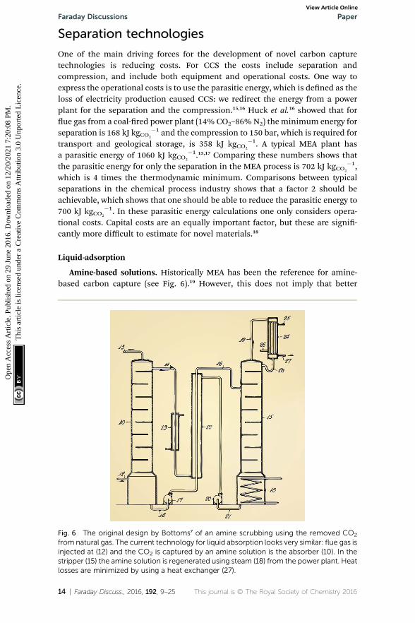
The problem of carbon capture from ue gasses is the nitrogen in the air. Ifone burns fossil fuels with pure oxygen, one would produce only CO2 and H2O,which can be separated by simply condensing the water. For such a process thebottleneck is the separation of oxygen from air. At present this is mainly done bycryogenic distillation (see Fig. 4) or through chemical looping (see Fig. 5). Inchemical looping one uses a solid oxygen carrier that is looping between twouidized beds. In one bed the solid adsorbs oxygen from the air and the oxygen-
Fig. 3 (a) Coal fired power plant and (b) coal fired power plant with carbon capture andcompression for geological storage (figure adopted from Smit et al.3).
12 | Faraday Discuss., 2016, 192, 9–25 This journal is © The Royal Society of Chemistry 2016
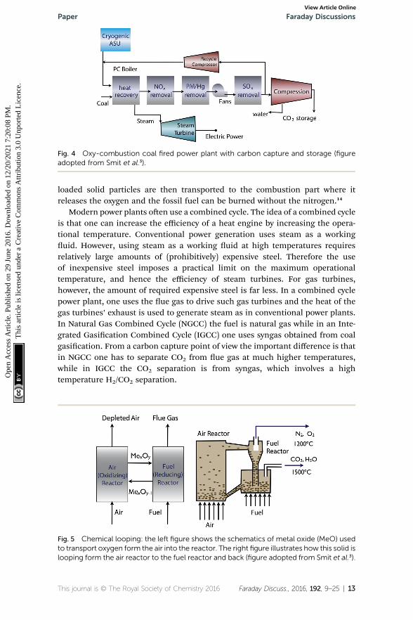
Fig. 4 Oxy-combustion coal fired power plant with carbon capture and storage (figureadopted from Smit et al.3).
Paper Faraday DiscussionsO
pen
Acc
ess
Art
icle
. Pub
lishe
d on
29
June
201
6. D
ownl
oade
d on
12/
20/2
021
7:20
:08
PM.
Thi
s ar
ticle
is li
cens
ed u
nder
a C
reat
ive
Com
mon
s A
ttrib
utio
n 3.
0 U
npor
ted
Lic
ence
.View Article Online
loaded solid particles are then transported to the combustion part where itreleases the oxygen and the fossil fuel can be burned without the nitrogen.14
Modern power plants oen use a combined cycle. The idea of a combined cycleis that one can increase the efficiency of a heat engine by increasing the opera-tional temperature. Conventional power generation uses steam as a workinguid. However, using steam as a working uid at high temperatures requiresrelatively large amounts of (prohibitively) expensive steel. Therefore the useof inexpensive steel imposes a practical limit on the maximum operationaltemperature, and hence the efficiency of steam turbines. For gas turbines,however, the amount of required expensive steel is far less. In a combined cyclepower plant, one uses the ue gas to drive such gas turbines and the heat of thegas turbines’ exhaust is used to generate steam as in conventional power plants.In Natural Gas Combined Cycle (NGCC) the fuel is natural gas while in an Inte-grated Gasication Combined Cycle (IGCC) one uses syngas obtained from coalgasication. From a carbon capture point of view the important difference is thatin NGCC one has to separate CO2 from ue gas at much higher temperatures,while in IGCC the CO2 separation is from syngas, which involves a hightemperature H2/CO2 separation.
Fig. 5 Chemical looping: the left figure shows the schematics of metal oxide (MeO) usedto transport oxygen form the air into the reactor. The right figure illustrates how this solid islooping form the air reactor to the fuel reactor and back (figure adopted from Smit et al.3).
This journal is © The Royal Society of Chemistry 2016 Faraday Discuss., 2016, 192, 9–25 | 13
Faraday Discussions PaperO
pen
Acc
ess
Art
icle
. Pub
lishe
d on
29
June
201
6. D
ownl
oade
d on
12/
20/2
021
7:20
:08
PM.
Thi
s ar
ticle
is li
cens
ed u
nder
a C
reat
ive
Com
mon
s A
ttrib
utio
n 3.
0 U
npor
ted
Lic
ence
.View Article Online
Separation technologies
One of the main driving forces for the development of novel carbon capturetechnologies is reducing costs. For CCS the costs include separation andcompression, and include both equipment and operational costs. One way toexpress the operational costs is to use the parasitic energy, which is dened as theloss of electricity production caused CCS: we redirect the energy from a powerplant for the separation and the compression.15,16 Huck et al.16 showed that forue gas from a coal-red power plant (14% CO2–86%N2) the minimum energy forseparation is 168 kJ kgCO2
�1 and the compression to 150 bar, which is required fortransport and geological storage, is 358 kJ kgCO2
�1. A typical MEA plant hasa parasitic energy of 1060 kJ kgCO2
�1.15,17 Comparing these numbers shows thatthe parasitic energy for only the separation in the MEA process is 702 kJ kgCO2
�1,which is 4 times the thermodynamic minimum. Comparisons between typicalseparations in the chemical process industry shows that a factor 2 should beachievable, which shows that one should be able to reduce the parasitic energy to700 kJ kgCO2
�1. In these parasitic energy calculations one only considers opera-tional costs. Capital costs are an equally important factor, but these are signi-cantly more difficult to estimate for novel materials.18
Liquid-adsorption
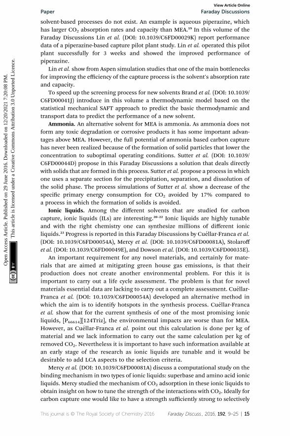
Amine-based solutions. Historically MEA has been the reference for amine-based carbon capture (see Fig. 6).19 However, this does not imply that better
Fig. 6 The original design by Bottoms7 of an amine scrubbing using the removed CO2
from natural gas. The current technology for liquid absorption looks very similar: flue gas isinjected at (12) and the CO2 is captured by an amine solution is the absorber (10). In thestripper (15) the amine solution is regenerated using steam (18) from the power plant. Heatlosses are minimized by using a heat exchanger (27).
14 | Faraday Discuss., 2016, 192, 9–25 This journal is © The Royal Society of Chemistry 2016
Paper Faraday DiscussionsO
pen
Acc
ess
Art
icle
. Pub
lishe
d on
29
June
201
6. D
ownl
oade
d on
12/
20/2
021
7:20
:08
PM.
Thi
s ar
ticle
is li
cens
ed u
nder
a C
reat
ive
Com
mon
s A
ttrib
utio
n 3.
0 U
npor
ted
Lic
ence
.View Article Online
solvent-based processes do not exist. An example is aqueous piperazine, whichhas larger CO2 absorption rates and capacity than MEA.19 In this volume of theFaraday Discussions Lin et al. (DOI: 10.1039/C6FD00029K) report performancedata of a piperazine-based capture pilot plant study. Lin et al. operated this pilotplant successfully for 3 weeks and showed the improved performance ofpiperazine.
Lin et al. show from Aspen simulation studies that one of the main bottlenecksfor improving the efficiency of the capture process is the solvent's absorption rateand capacity.
To speed up the screening process for new solvents Brand et al. (DOI: 10.1039/C6FD00041J) introduce in this volume a thermodynamic model based on thestatistical mechanical SAFT approach to predict the basic thermodynamic andtransport data to predict the performance of a new solvent.
Ammonia. An alternative solvent for MEA is ammonia. As ammonia does notform any toxic degradation or corrosive products it has some important advan-tages above MEA. However, the full potential of ammonia based carbon capturehas never been realized because of the formation of solid particles that lower theconcentration to suboptimal operating conditions. Sutter et al. (DOI: 10.1039/C6FD00044D) propose in this Faraday Discussions a solution that deals directlywith solids that are formed in this process. Sutter et al. propose a process in whichone uses a separate section for the precipitation, separation, and dissolution ofthe solid phase. The process simulations of Sutter et al. show a decrease of thespecic primary energy consumption for CO2 avoided by 17% compared toa process in which the formation of solids is avoided.
Ionic liquids. Among the different solvents that are studied for carboncapture, ionic liquids (ILs) are interesting.20–22 Ionic liquids are highly tunableand with the right chemistry one can synthesize millions of different ionicliquids.23 Progress is reported in this Faraday Discussions by Cuellar-Franca et al.(DOI: 10.1039/C6FD00054A), Mercy et al. (DOI: 10.1039/C6FD00081A), Stolaroffet al. (DOI: 10.1039/C6FD00049E), and Dowson et al. (DOI: 10.1039/C6FD00035E).
An important requirement for any novel materials, and certainly for mate-rials that are aimed at mitigating green house gas emissions, is that theirproduction does not create another environmental problem. For this it isimportant to carry out a life cycle assessment. The problem is that for novelmaterials essential data are lacking to carry out a complete assessment. Cuellar-Franca et al. (DOI: 10.1039/C6FD00054A) developed an alternative method inwhich the aim is to identify hotspots in the synthesis process. Cuellar-Francaet al. show that for the current synthesis of one of the most promising ionicliquids, [P66614][124Triz], the environmental impacts are worse than for MEA.However, as Cuellar-Franca et al. point out this calculation is done per kg ofmaterial and we lack information to carry out the same calculation per kg ofremoved CO2. Nevertheless it is important to have such information available atan early stage of the research as ionic liquids are tunable and it would bedesirable to add LCA aspects to the selection criteria.
Mercy et al. (DOI: 10.1039/C6FD00081A) discuss a computational study on thebinding mechanism in two types of ionic liquids: superbase and amino acid ionicliquids. Mercy studied the mechanism of CO2 adsorption in these ionic liquids toobtain insight on how to tune the strength of the interactions with CO2. Ideally forcarbon capture one would like to have a strength sufficiently strong to selectively
This journal is © The Royal Society of Chemistry 2016 Faraday Discuss., 2016, 192, 9–25 | 15
Faraday Discussions PaperO
pen
Acc
ess
Art
icle
. Pub
lishe
d on
29
June
201
6. D
ownl
oade
d on
12/
20/2
021
7:20
:08
PM.
Thi
s ar
ticle
is li
cens
ed u
nder
a C
reat
ive
Com
mon
s A
ttrib
utio
n 3.
0 U
npor
ted
Lic
ence
.View Article Online
adsorb CO2 at a sufficiently high capacity, but not too strong as this may makeregeneration more expensive.
A practical issue that is oen observed in ionic liquids is that they tend to beviscous. An increased viscosity reduces mass transfer and makes these ionicliquids less efficient, as one would expect on purely thermodynamic grounds. Tomitigate these negative effects of ionic liquids Stolaroff et al. (DOI: 10.1039/C6FD00049E) discuss a methodology to encapsulate ionic liquids with a semi-permeable membrane. This membrane is permeable to CO2 but not to thesolvent. Stolaroff et al. showed that for these Micro-Encapsulated CO2 Sorbents(MECS) the rate of CO2 absorption is enhanced by a factor 3.5 compared to a lmof ionic liquids.
A different solution for the mass-transfer limitations of ionic liquids isproposed in the Discussions by Dowson et al. (DOI: 10.1039/C6FD00035E).Dowson et al. use an ionic liquid that is in the solid phase at the condition ofinterest. To increase the surface area of this solid ionic liquid (SoIL), the solidswere nely ground. In a pressure swing operation, Dowson et al. illustrated thefeasibility of the process: compared to similar ILs the capacity was decreased butthe uptake rate was signicantly faster.
Solid adsorption
An alternative to liquid absorption is to use solid adsorbents. The focus of most ofthis scientic research is to nd novel materials that can capture CO2 moreefficiently.24 However, from a process engineering point of view solids are moredifficult to handle compared to liquids. For example, liquids can be pumped,which makes it simple to develop a continuous process with full heat integration.Solid adsorption is usually envisioned as a batch process with two beds ofadsorbents: one bed is in adsorption mode while the other is in regenerationmode. It is possible to use solids in continuous operation by using a uidized bedor by using a simulated moving bed.3 Alternatively one can make a slurry of solidparticles in a solvent, which can be pumped.25
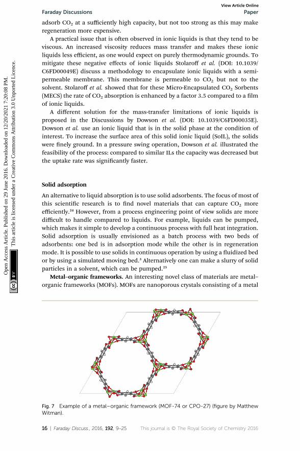
Metal–organic frameworks. An interesting novel class of materials are metal–organic frameworks (MOFs). MOFs are nanoporous crystals consisting of a metal
Fig. 7 Example of a metal–organic framework (MOF-74 or CPO-27) (figure by MatthewWitman).
16 | Faraday Discuss., 2016, 192, 9–25 This journal is © The Royal Society of Chemistry 2016
Paper Faraday DiscussionsO
pen
Acc
ess
Art
icle
. Pub
lishe
d on
29
June
201
6. D
ownl
oade
d on
12/
20/2
021
7:20
:08
PM.
Thi
s ar
ticle
is li
cens
ed u
nder
a C
reat
ive
Com
mon
s A
ttrib
utio
n 3.
0 U
npor
ted
Lic
ence
.View Article Online
node connected with an organic linker (see Fig. 7).26 These materials have veryhigh surface areas. The most interesting aspect is their chemical tunability; bychanging the metal and linker one can synthesize millions of different materials.A scientic challenge is to explore this tunability to nd the best material forcarbon capture.24,27 These Faraday Discussions report contributions by Cresswellet al. (DOI: 10.1039/C6FD00026F), Joos et al. (DOI: 10.1039/C6FD00031B), Man-gano et al. (DOI: 10.1039/C6FD00045B), and Hei et al. (10.1039/C6FD00040A).
To compare differentmaterials one needs to have ametric. Huck et al.16 used theparasitic energy (i.e. the loss of produced electricity), to evaluate the performance ofMOFs for carbon capture and sequestration. Most of these calculations rely onaccurate thermodynamic data. If accurate experimental data are missing, one canrely on molecular simulations to predict the adsorption behavior in these mate-rials. Or, as discussed in the article by Cresswell et al. (DOI: 10.1039/C6FD00026F),to predict the effects of impurities on the thermodynamic properties of CO2.
For some practical applications it may not be necessary to compress CO2 orhave CO2 at such a high purity. Joos et al. (DOI: 10.1039/C6FD00031B) discuss howchanging the purity requirement inuences the selection of an adsorptionmaterial.
The thermodynamic variables are not the only important criteria discussed byMangano et al. (DOI: 10.1039/C6FD00045B), who report the stability of Mg- andNi-CPO-27 (also referred to as MOF-74, see Fig. 7) upon adsorption of wet uegasses. Mangano et al. show that Mg-CPO-27 rapidly degenerates, while Ni-CPO-27 remains relatively stable. In this context it is important to realize that MOFsrepresent a class of materials; some of MOFs are unstable in water but someothers can be boiled in acids. In addition to chemical stability it is also importantto study the mechanical stability of these materials. In practical applications thepressure exerted on these materials can be very high.
Most MOFs that can selectively adsorb CO2 from ue gasses require dry uegasses, as those materials that are selective for CO2 oen have an even greateraffinity for water. To mitigate the negative interference from water, amine-appended MOFs have been developed.28 Of particular interest are those amineappended MOFs that show a phase transition. This phase transition is associatedwith the collective behavior of the amines, which form chains upon the adsorp-tion of CO2.29–31 In addition by changing the metal the CO2 pressure at which thetransition takes place can be tuned.29–31 Hei et al. (DOI: 10.1039/C6FD00040A)discuss the potential of these new materials for carbon capture in a temperatureswing adsorption process. Hei et al. showed that the specic energy requirementof this process operated with these materials is lower than for a commercial 13Xzeolite. In particular, the fact that these isotherms show a step allows for a smallertemperature swing compared to conventional materials.
Membranes separations
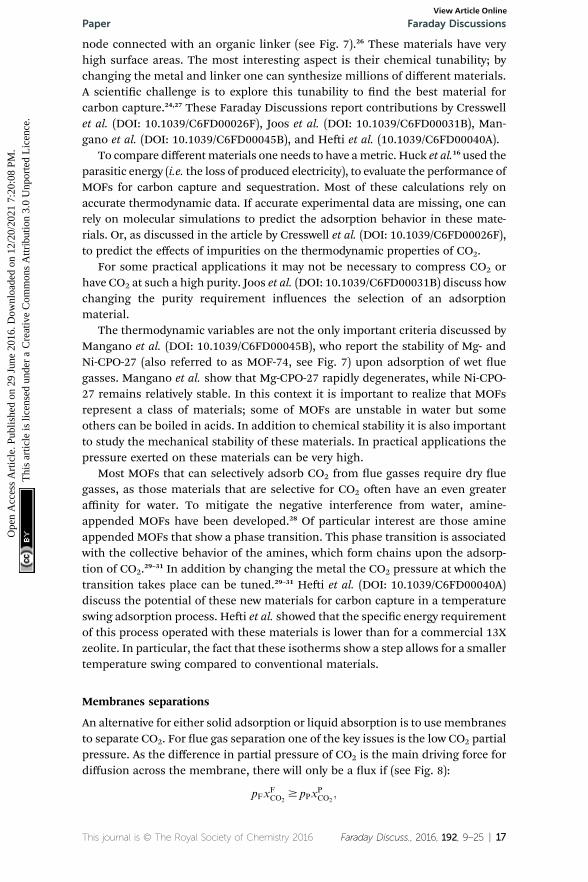
An alternative for either solid adsorption or liquid absorption is to usemembranesto separate CO2. For ue gas separation one of the key issues is the low CO2 partialpressure. As the difference in partial pressure of CO2 is the main driving force fordiffusion across the membrane, there will only be a ux if (see Fig. 8):
pFxFCO2
$ pPxPCO2
;
This journal is © The Royal Society of Chemistry 2016 Faraday Discuss., 2016, 192, 9–25 | 17
Faraday Discussions PaperO
pen
Acc
ess
Art
icle
. Pub
lishe
d on
29
June
201
6. D
ownl
oade
d on
12/
20/2
021
7:20
:08
PM.
Thi
s ar
ticle
is li
cens
ed u
nder
a C
reat
ive
Com
mon
s A
ttrib
utio
n 3.
0 U
npor
ted
Lic
ence
.View Article Online
where p is the pressure, x the composition, and sub- and superscripts P and Frefer to the permeate and feed, respectively. If we take a typical ue gas from a gas-red power plant, xFCO2
¼ 0:05; and assume 90% capture, xPCO2¼ 0:9; we see that
the ratio between the pressure of the feed (ue gas) and the permeate on the otherside of the membrane has to be:
pF
pP$
xPCO2
xFCO2
¼ 0:9
0:05¼ 18:
One can create this ratio in pressures by compressing ue gas or pullingvacuum on the permeate side. However, given the large volume of ue gas, sucha large ratio would require more power than is produced by the power plant, andin practice the maximum ratio that can be achieved is 5. This simple argumentshows that a single stage membrane separation cannot achieve the requirementsfor carbon capture. Of course, one can achieve the required purity with a two-stageprocess (i.e. two membranes) but at the expense of twice the compression costs,which makes such a two-stage membrane separation impractical. Merkel et al.32
developed an alternative design using two membranes where in the rstmembrane an air sweep is used to increase the concentration of CO2 in the air,which is subsequently used for the combustion. As the partial pressure of CO2 inthe air is very small even at atmospheric pressure on the feed side, there is stilla very large driving force. As we now burn fossil fuels with air, which has muchhigher CO2 concentrations, we are “articially” increasing xFCO2
; hence we nowhave a pressure ratio that is much smaller.
From a material design point of view the issue of designing a membrane isa balance between selectivity and permeability. For most polymer membranes oneis confronted with the Robeson upper bound.33,34 Robeson observed that for most
Fig. 8 Schematics of a membrane where feed is the flue gas that enters the membranewith a pressure pF and composition xFCO2
. Most membranes have a higher permeability forCO2 and therefore the permeate is rich in CO2 ðxPCO2
Þ while the retentate is CO2 poor(figure adopted from Smit et al.3).
18 | Faraday Discuss., 2016, 192, 9–25 This journal is © The Royal Society of Chemistry 2016
Paper Faraday DiscussionsO
pen
Acc
ess
Art
icle
. Pub
lishe
d on
29
June
201
6. D
ownl
oade
d on
12/
20/2
021
7:20
:08
PM.
Thi
s ar
ticle
is li
cens
ed u
nder
a C
reat
ive
Com
mon
s A
ttrib
utio
n 3.
0 U
npor
ted
Lic
ence
.View Article Online
polymers if one would like to enhance the ux through the membrane, one needsto have a material with “bigger” cavities to increase the permeability, but creatingbigger cavities reduces the selectivity. Hence, for a given permeability there is anupper boundary of the selectivity for a given permeability. Interestingly such anupper boundary does not exist for membranes composed of nanoporousmaterials.35
Membrane separations are based on differences in the permeability of thegasses when they pass through the material. The permeability is the product ofthe solubility and diffusion coefficient of these gasses. For most materials CO2
has the highest permeability. One can enhance the permeability if in the materialCO2 gets converted to H2CO3. This so-called facilitated transport is used bysystems in nature to selectively transport CO2.
In these Faraday Discussions we have contributions from Anantharaman et al.(DOI: 10.1039/C6FD00038J) and Zhang et al. (DOI: 10.1039/C6FD00030D).
Anantharaman et al. (DOI: 10.1039/C6FD00038J) discuss the potential ofhighly CO2-selective dual-phase membranes. These membranes consist ofa porous solid phase matrix lled with a molten carbonate phase. Unlikeconventional polymer membranes these materials operate at high temperatures(400 �C). At these high temperatures CO2 can be ionized to form CO3
2�, which ishighly mobile in the molten carbonate phase. In such a system the driving force isthe gradient of the electrochemical potential. Because this membrane operates athigh temperatures, it is less useful for the conventional low-temperature post-combustion carbon capture. However, alternative processes such as the NaturalGas Combined Cycle (NGCC) or Integrated Gasication Combined Cycle (IGCC)operate at exactly these high temperatures.
The issue with NGCC is that, like in conventional post-combustion, carboncapture occurs at a low concentration of CO2. Anantharaman et al. (DOI: 10.1039/C6FD00038J) show that this low concentration makes a high temperaturemembrane less favorable compared to amine scrubbing. For IGCC, however,Anantharaman et al. show that this separation with these high temperatures ischeaper compared to MEA scrubbing. Zhang et al. (DOI: 10.1039/C6FD00030D)discuss addressing the low concentration of CO2 in the IGCC process usinga membrane-amine hybrid solution. Zhang et al. propose to use a membrane withair sweep to obtain a CO2 enriched ue gas, in which the CO2 is subsequentlycaptured using amine (piperazine) scrubbing.
Chemical looping
Whereas the main focus of chemical looping is to provide pure oxygen forcombustion, it is also possible to use a solid to remove CO2 from ue gasses.36 Inthis application a metal oxide is used to capture CO2 from the ue gas:
Capture: MxO + CO2 % MxCO3
Regeneration: MxCO3 % MxO + CO2
This Faraday Discussions contains contributions on chemical looping fromDunstan et al. (DOI: 10.1039/C6FD00047A), Li et al. (10.1039/C6FD00019C),
This journal is © The Royal Society of Chemistry 2016 Faraday Discuss., 2016, 192, 9–25 | 19
Faraday Discussions PaperO
pen
Acc
ess
Art
icle
. Pub
lishe
d on
29
June
201
6. D
ownl
oade
d on
12/
20/2
021
7:20
:08
PM.
Thi
s ar
ticle
is li
cens
ed u
nder
a C
reat
ive
Com
mon
s A
ttrib
utio
n 3.
0 U
npor
ted
Lic
ence
.View Article Online
Naeem et al. (DOI: 10.1039/C6FD00042H), and Erans et al. (DOI: 10.1039/C6FD00027D).
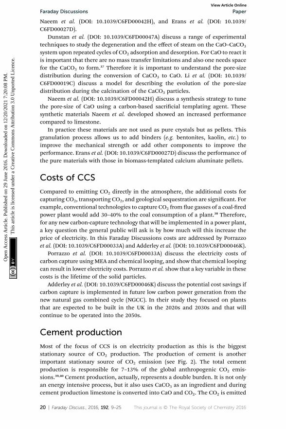
Dunstan et al. (DOI: 10.1039/C6FD00047A) discuss a range of experimentaltechniques to study the degeneration and the effect of steam on the CaO–CaCO3
system upon repeated cycles of CO2 adsorption and desorption. For CaO to react itis important that there are no mass transfer limitations and also one needs spacefor the CaCO3 to form.37 Therefore it is important to understand the pore-sizedistribution during the conversion of CaCO3 to CaO. Li et al. (DOI: 10.1039/C6FD00019C) discuss a model for describing the evolution of the pore-sizedistribution during the calcination of the CaCO3 particles.
Naeem et al. (DOI: 10.1039/C6FD00042H) discuss a synthesis strategy to tunethe pore-size of CaO using a carbon-based sacricial templating agent. Thesesynthetic materials Naeem et al. developed showed an increased performancecompared to limestone.
In practice these materials are not used as pure crystals but as pellets. Thisgranulation process allows us to add binders (e.g. bentonites, kaolin, etc.) toimprove the mechanical strength or add other components to improve theperformance. Erans et al. (DOI: 10.1039/C6FD00027D) discuss the performance ofthe pure materials with those in biomass-templated calcium aluminate pellets.
Costs of CCS
Compared to emitting CO2 directly in the atmosphere, the additional costs forcapturing CO2, transporting CO2, and geological sequestration are signicant. Forexample, conventional technologies to capture CO2 from ue gasses of a coal-redpower plant would add 30–40% to the coal consumption of a plant.38 Therefore,for any new carbon-capture technology that will be implemented in a power plant,a key question the general public will ask is by how much will this increase theprice of electricity. In this Faraday Discussions costs are addressed by Porrazzoet al. (DOI: 10.1039/C6FD00033A) and Adderley et al. (DOI: 10.1039/C6FD00046K).
Porrazzo et al. (DOI: 10.1039/C6FD00033A) discuss the electricity costs ofcarbon capture usingMEA and chemical looping, and show that chemical loopingcan result in lower electricity costs. Porrazzo et al. show that a key variable in thesecosts is the lifetime of the solid particles.
Adderley et al. (DOI: 10.1039/C6FD00046K) discuss the potential cost savings ifcarbon capture is implemented in future low carbon power generation from thenew natural gas combined cycle (NGCC). In their study they focused on plantsthat are expected to be built in the UK in the 2020s and 2030s and that willcontinue to be operated into the 2050s.
Cement production
Most of the focus of CCS is on electricity production as this is the biggeststationary source of CO2 production. The production of cement is anotherimportant stationary source of CO2 emission (see Fig. 2). The total cementproduction is responsible for 7–13% of the global anthropogenic CO2 emis-sions.39,40 Cement production, actually, represents a double burden. It is not onlyan energy intensive process, but it also uses CaCO3 as an ingredient and duringcement production limestone is converted into CaO and CO2. The CO2 is emitted
20 | Faraday Discuss., 2016, 192, 9–25 This journal is © The Royal Society of Chemistry 2016
Paper Faraday DiscussionsO
pen
Acc
ess
Art
icle
. Pub
lishe
d on
29
June
201
6. D
ownl
oade
d on
12/
20/2
021
7:20
:08
PM.
Thi
s ar
ticle
is li
cens
ed u
nder
a C
reat
ive
Com
mon
s A
ttrib
utio
n 3.
0 U
npor
ted
Lic
ence
.View Article Online
with the ue gasses. CCS is therefore an important technology for the cementindustry to reduce their CO2 emissions. The ue gas composition from cementproduction is slightly different from the ue gas from power plants; therefore onecan use the post-combustion carbon capture technologies used in power plants.41
One can also opt for pre-combustion carbon capture and here we can also use CO2
diluted oxygen for the combustion.Even if one uses air or oxygen to burn fossil fuels this has little impact on
electricity production as it does not inuence the quality of the steam that isproduced. Cement that is produced in an oxy-combustion environment hasdifferent properties from cement that is produced traditionally by combustion inair. In this Faraday Discussions Zheng et al. (DOI: 10.1039/C6FD00032K) report onthe quality of cement that is produced by oxy-combustion and show that high-quality cement can be successfully produced in an oxy-fuel atmosphere.
Negative CO2 emissions
If one looks at the fate of CO2 emitted in the atmosphere, one can see that about30% ends up as increased terrestrial biomass and 25% in the surface of the oceaneither as biomass or dissolved in the water. The remainder stays in the atmo-sphere. If we were to stop emitting any CO2 tomorrow it would take over 200 yearsbefore these CO2 levels decreased to preindustrial levels.3 The reason for theselong times is the slow mixing of the surface of the ocean with the deep ocean. Forall practical purposes we can therefore assume that 45% of all the CO2 we emitnow will stay “forever” in the atmosphere. This implies that if we overshoot ourtarget atmospheric CO2 concentration we cannot wait until nature takes care ofthis overshoot; the only solution is to actively reduce the CO2 concentration in theatmosphere. Direct air capture is a technology that aims to achieve this.42–46 As airhas a much lower concentration of CO2, the costs of capturing a CO2 moleculeonce it has been emitted in the atmosphere are signicantly larger than capturingit from amore concentrated source.47 A cheaper alternative for direct air capture isto co-re biomass in a coal-red plant and subsequently sequester the CO2.Bioenergy with Carbon Capture and Storage (BECCS) is seen as a promisingtechnology to achieve negative emissions using current infrastructures. A keyquestion is the source of the biomass. Initially the focus will be on waste biomass,however, there is a limit to the total available waste biomass, and if one needs togrow biomass for BECCS there is the question of competition with foodproduction and changes in land use.
In this Faraday Discussions Mac Dowell and Fajardy (DOI: 10.1039/C6FD00051G) compare BECCS in combination with post-combustion and oxy-combustion carbon capture. They showed that going to negative CO2 emissiondoes not come for free. The efficiency of power plants with BECCS will depend onthe moisture content of the biomass and co-ring rate, but in general the effi-ciency will be lower than the efficiency of conventional power plants with CCS.
Geological storage
Given the extremely large volumes of CO2 we are producing, converting CO2 intouseful products or fuels can only mitigate a small fraction of the CO2 we produce.Therefore, if we want to have an impact on total emissions, the bulk of the CO2
This journal is © The Royal Society of Chemistry 2016 Faraday Discuss., 2016, 192, 9–25 | 21
Faraday Discussions PaperO
pen
Acc
ess
Art
icle
. Pub
lishe
d on
29
June
201
6. D
ownl
oade
d on
12/
20/2
021
7:20
:08
PM.
Thi
s ar
ticle
is li
cens
ed u
nder
a C
reat
ive
Com
mon
s A
ttrib
utio
n 3.
0 U
npor
ted
Lic
ence
.View Article Online
that is being produced will have to be permanently stored. Geological formationsare an option for permanent CO2 storage. Geological analysis shows that we havea sufficient number of geological formations to store all the CO2 that we will beproducing.
An important factor in geological storage is the perception of the public. In thecontext of enhanced oil recovery we have quite some experience in transportingCO2 and injecting CO2 in geological formations. However, we do not have expe-rience with injecting CO2 on such a large scales as is required to make a signi-cant impact on emissions. Therefore research on geological storage is focused onincreasing our knowledge of how to ensure the safe and permanent sequestrationof CO2.
Of particular importance for geological storage are aquifers, which are sand-stone formations in which the pores are lled with brine. If one injects CO2 inthese formations one has to understand the chemical interactions between theCO2 and the reservoir uids and rocks. For example, the dissolved CO2 makes thebrine solution more acidic and this acidic solution may interact with the rocksand change the properties of the formation. In this Faraday Discussions Penget al. (DOI: 10.1039/C6FD00048G) study the dissolution rate of several typicalcarbonate minerals, which one can nd in these formations, in CO2-saturatedwater or brine at typical sequestration conditions. Quantifying these rates isimportant as these are the input for the computational models that are used topredict the fate of CO2 injected in these aquifers. These reservoir simulators areimportant as they are used to guide the CO2 injection process.
Outlook
The rst question to ask is whether any of the technologies that are discussed inthis article will be implemented. The most important factor in answering thisquestion will be whether there will be a sufficiently large price on emitting CO2.None of the technologies that we have discussed will make the burning of fossilfuels any cheaper; hence with such a price on carbon it is essential to recover thecosts. Whether we like it or not reducing CO2 emissions will cost money. In thiscontext it is important to realize that, according to the IPCC report, not employingCCS will make the reduction of CO2 emissions signicantly more expensive.1
Hence, if we are serious in reducing CO2 emissions, CCS will be part of the mix oftechnologies that will be employed.
A second question is which of the carbon capture technologies that we havediscussed will be employed. It is clear that the rst generation of carbon-capturetechnologies will be solvent based; several processes have already been developed.Whether the second or third generation carbon-capture plants will still use thistechnology is an open question. From a research point of view it is important togenerate as many options as possible. Novel solvents, solid adsorption,membranes, or hybrid-amine adsorptions are interesting alternatives. Costcalculations are normally used to select the most promising technologies forfurther development. It would be interesting to use these cost calculations at anearly stage of research. This would give the researchers some feedback on whichaspects of a process with a novel material could become a potential bottleneck forlarge-scale employment.
22 | Faraday Discuss., 2016, 192, 9–25 This journal is © The Royal Society of Chemistry 2016
Paper Faraday DiscussionsO
pen
Acc
ess
Art
icle
. Pub
lishe
d on
29
June
201
6. D
ownl
oade
d on
12/
20/2
021
7:20
:08
PM.
Thi
s ar
ticle
is li
cens
ed u
nder
a C
reat
ive
Com
mon
s A
ttrib
utio
n 3.
0 U
npor
ted
Lic
ence
.View Article Online
From a scientic point of view it is interesting to see research focused on tailor-made materials for a given separation. Ionic liquids can be tuned to have optimalproperties for carbon capture, as is the case for metal–organic frameworks(MOFs). These studies will give us important insights in what would be the idealmolecular structure to achieve such a separation. As these studies involvescreening of thousands of materials, many of these studies are integrated withcomputational approaches (i.e. materials genomics).15,23 As a rst step thesestudies are very successful in identifying the best materials for highly idealizedseparations (e.g. ue gasses without water),16 with materials that may not be idealfor such large-scale separations. Therefore it will be important to see how thisknowledge can be translated to materials that do meet all the requirements forpractical applications.
New materials may also require different processes. For example, solidadsorption or membrane separations are, from a process-engineering point ofview, more difficult than liquid adsorption. This raises the question as to whether,if the most ideal solid adsorbent or membrane is found, the process technology issufficiently developed to fully take advantage of these novel materials. In theseDiscussions we see some nice examples related to chemical looping on the type ofprogress that can be made in process engineering.
There is an important difference between mitigating CO2 emissions andmitigating acid rains. SOx and NOx emissions cause acid rain, but as soon as westop emitting SOx and NOx these gasses will be removed from the atmospherewith the acid rain, and the problem is solved. However, of all the emitted CO2,about 45% will stay for at least 200 years in the atmosphere. Even if we stopinvesting in fossil fuels tomorrow, it is unlikely that existing investments will bedemolished. Hence, we are already committed to CO2 emissions by our pastinvestments.48 This makes it likely that we will overshoot our targets and willtherefore need a much more aggressive search for technologies that reduce CO2
concentration in the atmosphere.
Acknowledgements
I would like to thank Matthew Witman for providing Fig. 7 and a careful proof-reading of the manuscript. The research leading to these results has receivedfunding from the European Research Council under the European Union'sSeventh Framework Programme (FP/2007-2013)/ERC Grant Agreement n.666983 –MaGic.
Notes and references
1 R. K. Pachauri and L. A. Meyer, Climate Change 2014: Synthesis Report.Contribution of Working Groups I, II and III to the Fih Assessment Report ofthe Intergovernmental Panel on Climate Change, ed. IPCC, IPCC, Geneva,Switzerland, 2014.
2 W. D. Nordhaus, The Climate Casino: Risk, Uncertainty, and Economics fora Warming World, Yale University Press, New Haven, 2013.
3 B. Smit, J. R. Reimer, C. M. Oldenburg and I. C. Bourg, Introduction to CarbonCapture and Sequestration, Imperial College Press, London, 2014.
4 J. Wilcox, Carbon Capture, Springer, New York, 2012.
This journal is © The Royal Society of Chemistry 2016 Faraday Discuss., 2016, 192, 9–25 | 23
Faraday Discussions PaperO
pen
Acc
ess
Art
icle
. Pub
lishe
d on
29
June
201
6. D
ownl
oade
d on
12/
20/2
021
7:20
:08
PM.
Thi
s ar
ticle
is li
cens
ed u
nder
a C
reat
ive
Com
mon
s A
ttrib
utio
n 3.
0 U
npor
ted
Lic
ence
.View Article Online
5 M. E. Boot-Handford, J. C. Abanades, E. J. Anthony, M. J. Blunt, S. Brandani,N. Mac Dowell, J. R. Fernandez, M. C. Ferrari, R. Gross, J. P. Hallett,R. S. Haszeldine, P. Heptonstall, A. Lyngfelt, Z. Makuch, E. Mangano,R. T. J. Porter, M. Pourkashanian, G. T. Rochelle, N. Shah, J. G. Yao andP. S. Fennell, Energy Environ. Sci., 2014, 7, 130–189.
6 N. MacDowell, N. Florin, A. Buchard, J. Hallett, A. Galindo, G. Jackson,C. S. Adjiman, C. K. Williams, N. Shah and P. Fennell, Energy Environ. Sci.,2010, 3, 1645–1669.
7 R. Bottoms, Separating acid gases, US Pat., 1783901, 1930.8 G. T. Rochelle, Science, 2009, 325, 1652–1654.9 B. Smit, Greenhouse Gases: Sci. Technol., 2013, 3, 159–160.10 A. S. Bhown and B. C. Freeman, Environ. Sci. Technol., 2011, 45, 8624–8632.11 B. Smit, A.-H. A. Park and G. Gadikota, Front. Energ., 2014, 2, 55.12 J. D. Figueroa, T. Fout, S. Plasynski, H. McIlvried and R. D. Srivastava, Int. J.
Greenhouse Gas Control, 2008, 2, 9–20.13 J. P. Ciferno, J. J. Marano and R. K. Munson, Chem. Eng. Prog., 2011, 107, 34–44.14 L. S. Fan, L. Zeng and S. W. Luo, Chem. Eng. Prog., 2015, 111, 30–38.15 L.-C. Lin, A. H. Berger, R. L. Martin, J. Kim, J. A. Swisher, K. Jariwala,
C. H. Rycro, A. S. Bhown, M. W. Deem, M. Haranczyk and B. Smit, Nat.Mater., 2012, 11, 633–641.
16 J. M. Huck, L.-C. Lin, A. Berger, M. N. Shahrak, R. L. Martin, A. Bhown,M. Haranczyk, K. Reuter and B. Smit, Energy Environ. Sci., 2014, 7, 4136–4146.
17 M. Ramezan, T. J. Skone, N. ya Nsakala and G. N. Liljedahl, Carbon DioxideCapture from Existing Coal-red Power Plants, Report DOE/NETL-401/110907,National Energy Technology Laboratory, US Department of Energy, 2007.
18 R. Sathre and E. Masanet, RSC Adv., 2013, 3(15), 4964–4975.19 G. Rochelle, E. Chen, S. Freeman, D. Van Wagener, Q. Xu and A. Voice, Chem.
Eng. J., 2011, 171, 725–733.20 J. L. Anthony, S. N. V. K. Aki, E. J. Maginn and J. F. Brennecke, Int. J. Environ.
Technol. Manage., 2004, 4, 105–115.21 J. E. Brennecke and B. E. Gurkan, J. Phys. Chem. Lett., 2010, 1, 3459–3464.22 B. Gurkan, B. F. Goodrich, E. M. Mindrup, L. E. Ficke, M. Massel, S. Seo,
T. P. Senle, H. Wu, M. F. Glaser, J. K. Shah, E. J. Maginn, J. F. Brenneckeand W. F. Schneider, J. Phys. Chem. Lett., 2010, 1, 3494–3499.
23 F. Y. Yan, M. Lartey, K. Jariwala, S. Bowser, K. Damodaran, E. Albenze,D. R. Luebke, H. B. Nulwala, B. Smit and M. Haranczyk, J. Phys. Chem. B,2014, 118, 13609–13620.
24 D. M. D'Alessandro, B. Smit and J. R. Long, Angew. Chem., Int. Ed., 2010, 49,6058–6082.
25 H. Liu, B. Liu, L. C. Lin, G. J. Chen, Y. Q. Wu, J. Wang, X. T. Gao, Y. N. Lv,Y. Pan, X. X. Zhang, X. R. Zhang, L. Y. Yang, C. Y. Sun, B. Smit andW. C. Wang, Nat. Commun., 2014, 5, 5147.
26 H. Furukawa, K. E. Cordova, M. O'Keeffe and O. M. Yaghi, Science, 2013, 341,974.
27 K. Sumida, D. L. Rogow, J. A. Mason, T. M. McDonald, E. D. Bloch, Z. R. Herm,T.-H. Bae and J. R. Long, Chem. Rev., 2012, 112, 724–781.
28 T. M. McDonald, W. R. Lee, J. A. Mason, B. M. Wiers, C. S. Hong and J. R. Long,J. Am. Chem. Soc., 2012, 134, 7056–7065.
24 | Faraday Discuss., 2016, 192, 9–25 This journal is © The Royal Society of Chemistry 2016
Paper Faraday DiscussionsO
pen
Acc
ess
Art
icle
. Pub
lishe
d on
29
June
201
6. D
ownl
oade
d on
12/
20/2
021
7:20
:08
PM.
Thi
s ar
ticle
is li
cens
ed u
nder
a C
reat
ive
Com
mon
s A
ttrib
utio
n 3.
0 U
npor
ted
Lic
ence
.View Article Online
29 T. M. McDonald, J. A. Mason, X. Q. Kong, E. D. Bloch, D. Gygi, A. Dani,V. Crocella, F. Giordanino, S. O. Odoh, W. S. Drisdell, B. Vlaisavljevich,A. L. Dzubak, R. Poloni, S. K. Schnell, N. Planas, K. Lee, T. Pascal,L. W. F. Wan, D. Prendergast, J. B. Neaton, B. Smit, J. B. Kortright,L. Gagliardi, S. Bordiga, J. A. Reimer and J. R. Long, Nature, 2015, 519, 303–308.
30 B. Vlaisavljevich, S. O. Odoh, S. K. Schnell, A. L. Dzubak, K. Lee, N. Planas,J. B. Neaton, L. Gagliardi and B. Smit, Chem. Sci., 2015, 6, 5177–5185.
31 N. Planas, A. L. Dzubak, R. Poloni, L.-C. Lin, A. McManus, T. M. McDonald,J. B. Neaton, J. R. Long, B. Smit and L. Gagliardi, J. Am. Chem. Soc., 2013,135, 7402.
32 T. C. Merkel, H. Q. Lin, X. T. Wei and R. Baker, J. Membr. Sci., 2010, 359, 126–139.
33 L. M. Robeson, J. Membr. Sci., 1991, 62, 165–185.34 L. M. Robeson, J. Membr. Sci., 2008, 320, 390–400.35 J. Kim, M. Abouelnasr, L.-C. Lin and B. Smit, J. Am. Chem. Soc., 2013, 135,
7545–7552.36 E. J. Anthony, Ind. Eng. Chem. Res., 2008, 47, 1747–1754.37 P. S. Fennell, R. Pacciani, J. S. Dennis, J. F. Davidson and A. N. Hayhurst,
Energy Fuels, 2007, 21, 2072–2081.38 R. S. Haszeldine, Science, 2009, 325, 1647–1652.39 Climate Change 2014: Mitigation of Climate Change, Contribution of Working
Group III to the Fih Assessment, ed. O. Edenhofer, R. Pichs-Madruga,Y. Sokona, E. Farahani, S. Kadner, K. A. A. Seyboth, I. Baum, S. Brunner,P. Eickemeier, B. Kriemann, J. Savolainen, S. Schlomer, C. von Stechow,T. Zwickel and J. C. Minx, IPCC, 2014.
40 Report of the Intergovernmental Panel on Climate Change, Cambridge UniversityPress, Cambridge, United Kingdom and New York, NY, USA, 2014.
41 T. Hills, D. Leeson, N. Florin and P. Fennell, Environ. Sci. Technol., 2016, 50,368–377.
42 K. S. Lackner, Eur. Phys. J.: Spec. Top., 2009, 176, 93–106.43 K. S. Lackner, S. Brennan, J. M. Matter, A. H. A. Park, A. Wright and B. van der
Zwaan, Proc. Natl. Acad. Sci. U. S. A., 2012, 109, 13156–13162.44 D. W. Keith, Science, 2009, 325, 1654–1655.45 D. W. Keith, M. Ha-Duong and J. K. Stolaroff, Clim. Change, 2006, 74, 17–45.46 D. W. Keith, K. Heidel and R. Cherry, in Geo-engineering Climate Change :
Environmental Necessity or Pandora's Box?, ed. B. E. Launder and M. T.Thompson, Cambridge University Press, Cambridge, UK; New York, 2010,pp. 107–126.
47 R. Socolow, M. Desmond, R. Aines, J. Blackstock, O. Bolland, T. Kaarsberg,N. Lewis, M. Mazzotti, A. Pfeffer, K. Sawyer, J. Siirola, B. Smit and J. Wilcox,Direct Air Capture of CO2 with Chemicals: A Technology Assessment for the APSPanel on Public Affairs, American Physical Society, 2011.
48 S. J. Davis, K. Caldeira and H. D. Matthews, Science, 2010, 329, 1330–1333.
This journal is © The Royal Society of Chemistry 2016 Faraday Discuss., 2016, 192, 9–25 | 25