Embed Size (px)
Citation preview

International Journal of Advanced Robotic Systems Capuchin: A Free-Climbing Robot Invited Paper
Ruixiang Zhang1,* and Jean-Claude Latombe1 1 Computer Science Department, Stanford University, Stanford, CA, USA * Corresponding author E-mail: [email protected]
Accepted 2 Apr 2013 DOI: 10.5772/56469 © 2013 Zhang et al.; licensee InTech. This is an open access article distributed under the terms of the Creative Commons Attribution License (http://creativecommons.org/licenses/by/3.0), which permits unrestricted use, distribution, and reproduction in any medium, provided the original work is properly cited.
Abstract This paper describes an integrated quasi‐autonomous four‐limbed robot, named Capuchin, which is equipped with appropriate sensing, planning and control capabilities to “free‐climb” vertical terrain. Unlike aid climbing that takes advantage of special tools and/or engineered terrain features, free climbing only relies on friction at the contacts between the climber and the rigid terrain. While moving, Capuchin adjusts its body posture (hence, the position of its centre of mass) and exerts appropriate forces at the contacts in order to remain in equilibrium. Vision is used to achieve precise contacts and force sensing to control contact forces. The robot’s planner is based on a pre‐existing two‐stage “stance‐before‐motion” approach. Its controller applies a novel “lazy” force control strategy that performs force adjustments only when these are needed. Experiments demonstrate that Capuchin can reliably climb vertical terrain with irregular features. Keywords Climbing Robot, Equilibrium Maintenance, Force Control
1. Introduction
Compared to wheeled or track robots, legged robots are potentially more capable of travelling over steep and highly irregular terrain. Therefore, it is not surprising that much research has been carried out in recent years to
build quadruped robots [1], humanoid robots [2], and other multi‐limbed robots [3]. Various forms of locomotion have been achieved, but mostly on flat and horizontal terrain, or on regular and piecewise flat terrain (e.g., stairs). Some motion planners have been designed to allow legged robots to navigate without collision among obstacles [4], but with no or limited consideration for equilibrium. Other planners specifically focus on foot placements [5]. A small amount of research has studied dynamic locomotion on challenging terrain; Big Dog [1], a quadruped robot, is an impressive example of this line of research, but it is not equipped with motion planning capabilities. Other research has focused on learning navigation skills for quadruped robots on uneven, moderately sloped terrain [6]. To our knowledge however, there has been no major research project aimed at creating an integrated autonomous multi‐limbed robot, equipped with appropriate sensing, planning and control capabilities, to “free‐climb” vertical irregular terrain. In this paper, we describe our effort to create such a robot ‐ Capuchin. Unlike aid climbing that takes advantage of special equipment, tools and/or engineered terrain features, free climbing only relies on friction at the contacts between the climber and the rigid terrain. So, a human free‐climber moves on a steep rock crag or an artificial climbing wall using nothing else but his body (mostly his hands and feet) to make contacts with irregularly
1Ruixiang Zhang and Jean-Claude Latombe: Capuchin: A Free-Climbing Robotwww.intechopen.com
ARTICLE
www.intechopen.com Int J Adv Robotic Sy, 2013, Vol. 10, 194:2013

distributed terrain features, such as protrusions, holes, ledges and cracks (Figure 1). The climber alternatively breaks contacts and achieves new ones. Due to the irregularity of the terrain, each move is unique. While moving, the climber adjusts his body posture (hence, the position of his centre of mass) and exerts appropriate forces at the contacts in order to remain in equilibrium. A good climber almost always seems in quasi‐static equilibrium; although his motion seems relatively slow, it is smooth and fluid. This is the result of both deliberate planning and careful control using visual and tactile feedback. Vision is needed to detect terrain features and achieve precise contacts with them; tactile sensing is used to refine contact locations and exert appropriate forces. Contacts where the terrain points vertically upward are often promising to achieve balance, but they often do not exist, so contacts with other orientations must also be used. Equilibrium only requires that any force exerted by the body and gravitational force be balanced by other exerted forces. Because adopting adequate body postures, performing precise motion, and applying appropriate forces involve strategic thinking, free‐climbing is often regarded by human climbers both as a problem‐solving and a physical activity. Mere strength is not enough.
Figure 1. Finger contact with a small rock feature
Creating an autonomous free‐climbing robot is obviously a challenging research project. The motivations for this project are multi‐fold. First, it can lead to making basic progress in a number of important technical areas of robotics, such as complex planning, multi‐contact control, equilibrium maintenance, and delicate use of sensor feedback. In this context, a special motivation is that “cheating” is almost impossible: any significant imperfection in the integrated system will cause the robot to fall frequently. Conversely, if the robot operates successfully, it means that key issues must have been addressed satisfactorily. So, research on free‐climbing robots may eventually lead to developing effective methods that will benefit other multi‐limbed robots, even when such robots navigate on less challenging terrain. In addition, it may also contribute new techniques for
specific application areas, such as search‐and‐rescue in disaster environments, e.g., in rubble formed by collapsed buildings after an earthquake, and planetary exploration, e.g., to survey steep craters and cliffs on the Moon and Mars. This paper is organized as follows. Section 2 surveys some previous work on climbing robots. Section 3 describes the design of Capuchin hardware (kinematics, actuation, sensors). After formalizing the structure of a climbing motion and stating equilibrium constraints, Section 4 gives an overview of the motion planner used by Capuchin. Section 5 describes in detail the motion controller, which is based on a novel force control strategy that we call “lazy” force control. Section 6 gives a detailed account of one typical experiment performed with Capuchin. Section 7 suggests directions for future research.
2. Previous Climbing Robots
Various climbing robots have been created over the past 10‐15 years. Most rely on special tools and/or engineered environments. They are often equipped with end‐effectors, such as pegs, hooks and special grippers, that match engineered features of the environment, like holes, handrails, wire fences, bars and poles [7‐14]. Another family of climbing robots, adhesive robots, stick to flat or smoothly curved surfaces using devices like suction cups or magnets [15‐18]. Consequently, they are limited to environments consisting of glass, metal or other smooth surfaces. Bio‐inspired robot feet have been developed to create robots that can climb on building walls, tiles and other smooth surfaces. Among them, Stickybot [19] uses a rubber‐like material with tiny polymer hairs to mimic gecko‘s feet, while Spinybot [20] has feet equipped with many tiny claws. None of these robots could free‐climb vertical terrain with both small and large irregular features. Some robots specifically designed for pipe and duct inspection [21‐23] rely on frictional contacts with surfaces (as do free‐climbers), but take advantage of the geometric regularity of the cylindrical environment to perform pre‐computed cyclic gaited motion. To our knowledge, Lemur IIb (Figure 2(a)) represents the first attempt to build a free‐climbing robot. It is a planar four‐limbed climbing robot created by NASA’s Jet Propulsion Laboratory [24]. It consists of four identical limbs mounted on a circular chassis with equal spacing between them. The robot has a total mass of 7 kg. Each limb has three revolute joints, providing two in‐plane (“shoulder” and “elbow”) and one out‐of‐plane degrees of freedom. All joints are highly geared and have the same drive‐trains, capable of a maximum continuous torque of 5.0Nm and a maximum speed of 45deg/s. Each limb is equipped with a “finger”, a cylindrical peg wrapped with high‐friction rubber. The limb’s out‐of‐
2 Int J Adv Robotic Sy, 2013, Vol. 10, 194:2013 www.intechopen.com

plane degree of freedom allows the finger to pass over features mounted on the planar terrain. These features are of the same type as those used in climbing gyms. The robot’s elbow/knee joint can bend in both directions, but with a mechanical stop at 90deg. This 90deg limit restricts significantly the reachable workspace of each finger. It also complicates motion planning and control due to the non‐unique solution of the inverse kinematics of each limb. These lessons were taken into account in the design of Capuchin (Section 3).
(a) Lemur IIb [24]
(b) Tenzing [25]
Figure 2. Two previous free‐climbing robots
A planner was developed for Lemur IIb [26, 27]. This planner, which is based on a “stance‐before‐motion” approach, takes a model of the terrain as input, which lists all the possible points where the robot can make contact. Capuchin’s planner (Section 4) is an extended version of this planner [28]. An open‐loop position controller was implemented on Lemur IIb to execute the trajectories generated by the planner. Although this controller operates without force or vision feedback, Lemur IIb was nevertheless able to execute portions of the trajectories at very slow velocity to reduce positioning errors and slipping risks. But the resulting system was not reliable and Lemur IIb fell frequently. Falls were mainly caused by both positioning errors of the fingers and application of inadequate contact forces. Designing a
motion controller using vision and force feedback to perform reliable free‐climbing motions has been a key objective of our work with Capuchin. Tenzing (Figure 2(b)), another free‐climbing robot, was built at Dartmouth College [25]. Like Lemur IIb, it is a four‐limb planar robot with two revolute joints in each limb. A hobbyist servo motor is used on each elbow and shoulder joint. A force sensor is mounted at the endpoint of each limb to measure the magnitude of the vertical component of the contact force. The robot is also equipped with a tilt sensor used to keep its body upright. A camera, not mounted on the robot and located at some distance away from the climbing wall, is used to determine the position of the robot and locate terrain features on the wall. It is reported in [25] that the robot can climb in an interactive and an automatic mode. In the interactive mode, a human user enters a sequence of contacts on a graphic interface. In the automatic mode, a planner computes a path up the wall. The details of the planning and control algorithms are not provided in [25]. Tenzing has some obvious limitations that we tried to avoid in Capuchin. Hobbyist servo motors are inexpensive, but they have low joint angle precision. In addition, the belt used to drive each elbow joint increases backlash greatly. Therefore, precise position control may not be achievable. Tenzing’s force sensors only measure the vertical components of the contact forces. As this information is in general insufficient to maintain the robot in static equilibrium, Tenzing always keeps its body upright and can only climb walls equipped with relatively large terrain features having horizontal contact surfaces pointing upward (in blue in Figure 2(b)). The work presented in this paper is a continuation of previous research done at Stanford by Tim Bretl [26, 27, 29‐31], Kris Hauser [28, 32, 33] and Teresa Miller [34, 35]. The design of Capuchin benefitted from the experiments conducted by Bretl with Lemur IIb. The planner used by Capuchin was developed by Hauser and is based on the “stance‐before‐motion” approach pioneered by Bretl. Capuchin’s controller benefitted from our analysis of the limitations of an early controller designed and implemented by Miller on Capuchin.
3. Design of Capuchin
Robot design is a complicated process that requires making tradeoffs among many factors, such as functional capability and complexity, weight and strength of mechanical parts, weight and power of actuators, and cost and performance of sensors. Our keep‐it‐simple guideline has been to achieve the functions needed for free‐climbing with the simplest possible design.
3.1 Kinematic structure
One of our first important design decisions was that the end‐effector of each limb of the robot would be a small
3Ruixiang Zhang and Jean-Claude Latombe: Capuchin: A Free-Climbing Robotwww.intechopen.com

rigid cylindrical peg, called a finger. We also considered simple grippers, but to be useful they should have been able to exert large squeezing forces, for instance, to pinch small terrain protrusions. Hence, they would have considerably increased the weight and complexity of the robot. They would also have led to more complicated contact models in both the planning and control software. Although human climbers sometimes use several fingers to squeeze terrain features and their fists and feet to achieve secure jams in narrow cracks, most of their moves rely on simple contacts.
(a)
(b)
(c)
Figure 3. (a) Structure of Capuchin; (b) Capuchin on a climbing wall; (c) Finger in contact with feature
Another early important decision was that, while climbing, Capuchin should be in quasi‐static equilibrium at all times. This may sound as though it would be a major restriction, but good human climbers rarely perform fast dynamic moves, as such moves make it difficult to keep other contacts fixed and thus increase the risk of slipping and falling. Moreover, quasi‐static motion is sufficient to ascend a broad diversity of challenging vertical terrain. Nevertheless, exploiting momentum can be useful in some circumstances, for example, to reach a distant contact. Allowing such moves will be an interesting topic for future research (see Section 7). With only rigid cylindrical fingers to make contact with the terrain, the robot needs in general at least three simultaneous contacts in order to maintain static equilibrium. Hence, at least four limbs are required to allow one limb to move to a new contact, while the other three maintain balance. More limbs would allow more simultaneous contacts, hence could make it easier to achieve equilibrium. But this choice would also increase weight and complexity, as more degrees of freedom would have to be coordinated to avoid collision among limbs. This choice could only be beneficial on mildly challenging terrain with densely distributed useful contacts. These considerations and our keep‐it‐simple guideline led us to design Capuchin as a four‐limb robot, with two links on each limb. Our initial intention was to create a robot capable of climbing arbitrarily curved surfaces with protrusions and pockets. However, we quickly discovered that this goal was too ambitious for a first attempt at building an integrated climbing robot. So, as in Lemur IIb and Tenzing, we decided to restrict Capuchin’s climbing abilities to planar vertical surfaces equipped with protruding features (Section 3.2). The resulting robot is shown in Figures 3(a‐b). It is made up of two identical circular half‐bodies connected by a rigid link. Two limbs are attached to each half‐body, and each limb has two joints providing two in‐plane degrees of freedom: one in the shoulder between the body and the first link of the limb, the other in the elbow between the first and the second link of the limb. In the future, this design could be extended to non‐planar terrain by adding a joint in the link connecting the two half‐bodies and a joint in each shoulder (see Section 7).
3.2 Interaction with terrain
Figure 3(b) shows the robot on a climbing wall (terrain). This wall is a vertical planar board with artificial terrain features mounted on it (Figure 3(b‐c)). Each feature is a protruding plastic plate (green) with a distinct curved contour. It can be mounted anywhere on the board with any orientation. By selecting and distributing features differently, climbing terrains of various levels of difficulty
4 Int J Adv Robotic Sy, 2013, Vol. 10, 194:2013 www.intechopen.com
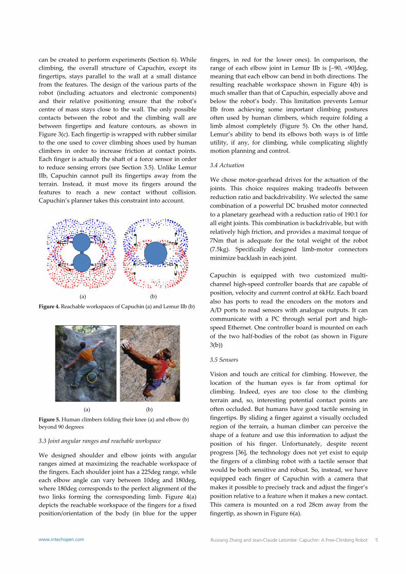
can be created to perform experiments (Section 6). While climbing, the overall structure of Capuchin, except its fingertips, stays parallel to the wall at a small distance from the features. The design of the various parts of the robot (including actuators and electronic components) and their relative positioning ensure that the robot’s centre of mass stays close to the wall. The only possible contacts between the robot and the climbing wall are between fingertips and feature contours, as shown in Figure 3(c). Each fingertip is wrapped with rubber similar to the one used to cover climbing shoes used by human climbers in order to increase friction at contact points. Each finger is actually the shaft of a force sensor in order to reduce sensing errors (see Section 3.5). Unlike Lemur IIb, Capuchin cannot pull its fingertips away from the terrain. Instead, it must move its fingers around the features to reach a new contact without collision. Capuchin’s planner takes this constraint into account.
(a) (b)
Figure 4. Reachable workspaces of Capuchin (a) and Lemur IIb (b)
(a) (b)
Figure 5. Human climbers folding their knee (a) and elbow (b) beyond 90 degrees
3.3 Joint angular ranges and reachable workspace
We designed shoulder and elbow joints with angular ranges aimed at maximizing the reachable workspace of the fingers. Each shoulder joint has a 225deg range, while each elbow angle can vary between 10deg and 180deg, where 180deg corresponds to the perfect alignment of the two links forming the corresponding limb. Figure 4(a) depicts the reachable workspace of the fingers for a fixed position/orientation of the body (in blue for the upper
fingers, in red for the lower ones). In comparison, the range of each elbow joint in Lemur IIb is [90, 90]deg, meaning that each elbow can bend in both directions. The resulting reachable workspace shown in Figure 4(b) is much smaller than that of Capuchin, especially above and below the robot’s body. This limitation prevents Lemur IIb from achieving some important climbing postures often used by human climbers, which require folding a limb almost completely (Figure 5). On the other hand, Lemur’s ability to bend its elbows both ways is of little utility, if any, for climbing, while complicating slightly motion planning and control.
3.4 Actuation
We chose motor‐gearhead drives for the actuation of the joints. This choice requires making tradeoffs between reduction ratio and backdrivability. We selected the same combination of a powerful DC brushed motor connected to a planetary gearhead with a reduction ratio of 190:1 for all eight joints. This combination is backdrivable, but with relatively high friction, and provides a maximal torque of 7Nm that is adequate for the total weight of the robot (7.5kg). Specifically designed limb‐motor connectors minimize backlash in each joint. Capuchin is equipped with two customized multi‐channel high‐speed controller boards that are capable of position, velocity and current control at 6kHz. Each board also has ports to read the encoders on the motors and A/D ports to read sensors with analogue outputs. It can communicate with a PC through serial port and high‐speed Ethernet. One controller board is mounted on each of the two half‐bodies of the robot (as shown in Figure 3(b))
3.5 Sensors
Vision and touch are critical for climbing. However, the location of the human eyes is far from optimal for climbing. Indeed, eyes are too close to the climbing terrain and, so, interesting potential contact points are often occluded. But humans have good tactile sensing in fingertips. By sliding a finger against a visually occluded region of the terrain, a human climber can perceive the shape of a feature and use this information to adjust the position of his finger. Unfortunately, despite recent progress [36], the technology does not yet exist to equip the fingers of a climbing robot with a tactile sensor that would be both sensitive and robust. So, instead, we have equipped each finger of Capuchin with a camera that makes it possible to precisely track and adjust the finger’s position relative to a feature when it makes a new contact. This camera is mounted on a rod 28cm away from the fingertip, as shown in Figure 6(a).
5Ruixiang Zhang and Jean-Claude Latombe: Capuchin: A Free-Climbing Robotwww.intechopen.com

(a) (b)
Figure 6. (a) Mounting of camera above a finger; (b) Force sensor
Forces exerted at contacts are also important information that a human climber feels in order to maintain balance and avoid slipping. So, we equipped each fingertip of Capuchin with a force sensor. We selected a strain gauge force sensor (Figure 6(b)) to equip each finger. It is a durable steel force sensor with a small size and light weight. One sensor is mounted at the extremity of each limb of Capuchin and, as mentioned before, the shaft of the sensor is used as the limb’s finger (Figure 3(c)). The sensor measures force components along three orthogonal directions up to a maximal net force of 50N, hence providing both the force magnitude and orientation in a plane parallel to the climbing wall. (The component of the force perpendicular to the wall is not currently used by our system.)
3.6 Computer and power supply
All computations for analysing sensor data, motion planning and motion control are performed on an off‐board computer connected to the two on‐board controllers and the four cameras. Power is also supplied through a tether cable. The connecting cables, which are visible beneath the robot in Figure 3(b), are light enough to have negligible effect on the robot’s climbing ability. The string visible above the robot only prevents the robot crashing to the ground if it falls. Representation of a configuration: We represent a configuration q of Capuchin by a list of 11 parameters: two are the coordinates of the centre point between the two half‐bodies in a Cartesian coordinate frame attached to the climbing wall, one is an angle defining the orientation of the robot’s body relative to this frame, and the other eight parameters are the coordinates of the fingers in this frame. Since each elbow can only bend in one direction, these parameters uniquely determine the shoulder and elbow angles.
4. Motion Planner
4.1 General scenario of free‐climbing
To ascend steep rock, a human free‐climber typically starts by looking at the entire terrain, or a large portion of it, to acquire a low‐resolution map of the major terrain features, such as major ledges, cracks, protrusions and pockets. Using this approximate map, he plans a coarse
navigation path that only gives high‐level direction, since detailed information about small features is still lacking. In general, except for new, yet un‐climbed terrain, published topo‐maps are often available and describe such coarse navigation paths along with terrain features that serve as landmarks. To start the ascent, the climber then visually acquires a detailed map of the terrain features, including tiny ones, around his current position. He identifies candidate contacts that can be used to move up, plans a few moves to reach an intermediate position along the coarse path, and executes them. While moving, the climber adjusts both the forces exerted at the contacts and the position of his centre of mass to remain in equilibrium. As he progresses, he acquires additional detailed information about the terrain, plans new moves to proceed further, etc. Occasionally, he may revise the coarse navigation path. So, a general scenario of free‐climbing includes the following steps: 1. Global sensing of the terrain and planning of coarse
navigation path. 2. Local sensing and detection of candidate contacts. 3. Detailed planning of a series of moves to reach an
intermediate goal position along the coarse path. 4. Execution of the moves. Steps 2, 3 and 4 are repeated until the climber reaches the final goal. This paper considers only a subset of this scenario. It focuses on steps 3 and 4 by assuming that a detailed map of the terrain and the candidate contacts are given as inputs. In this section we describe methods to plan moves that allow Capuchin to reach a final set of contacts from its current configuration on the terrain. In Section 5 we will describe the methods used to perform each move.
Figure 7. Capuchin moving its top‐right finger from one contact (red) to another contact (green)
6 Int J Adv Robotic Sy, 2013, Vol. 10, 194:2013 www.intechopen.com

4.2 Climbing moves and stances
As indicated in Section 3, Capuchin can only use its fingers to achieve contacts with the terrain features. Consider the situation shown in Figure 7(a) where all of its four fingers are positioned at contact points on the terrain. Assume that the short‐term goal of the robot is to move its top‐right finger from the contact shown in red to the contact shown in green. To break the contact in red, it must first adjust its posture to redistribute the contact forces applied by the three other fingers, so that the top‐right finger eventually applies a null force at the red contact. Figures 7(b) illustrates this motion and Figure 7(c) shows the configuration reached where the contact force at the red contact is null. Such force redistribution requires a move at a fixed set of four contacts. We call this set a 4‐stance. Once the contact force at the red contact becomes 0, the robot breaks this contact and moves at a fixed set of three contacts—a 3‐stance—to dock its top‐right finger at the green contact, as illustrated in Figures 7(d). The robot reaches the configuration shown in Figure 7(e). The force exerted at the new contact is initially null. To continue climbing, Capuchin will then have to break contact at one of the other three fingers, reach a new contact position with this finger, etc. So, overall, the entire climbing motion consists of successive steps, each of which changes a set of four contacts into a new set of four contacts differing from the former by one, single contact. Each step is made of two successive moves, the first at a 4‐stance to bring the contact force exerted by a finger to zero, the second at a 3‐stance to bring this finger to a new contact. In our current system, we do not allow stances with fewer than three contacts. Such stances have low utility for climbing and are rarely feasible.
4.3 Quasi‐static equilibrium constraints
As discussed in Section 3.1, we require Capuchin to remain in quasi‐static equilibrium throughout a climbing motion. This imposes that the robot applies adequate contact forces at each configuration q attained during the motion. Since the fingers are relatively small, we assume that each finger‐feature contact occurs at a single point that remains fixed when the link to which the finger is attached rotates. We model the contact by the two coordinates of that point, the direction of the normal to the feature contour at that point, and a friction coefficient (Figure 8).
Figure 8. Point contact
The reaction forces at the contacts must then satisfy the following conditions [27, 28]:
where (see Figure 9): pi, i = 1, ..., 4, denote the coordinate vectors of the (three
or four) contact points, fi, i = 1, ..., 4, are the component vectors of the reaction
forces at the contact points, mg is the component vector of the gravitational force, CM(q) is the coordinate vector of the centre of mass of
the robot at configuration q, FCi, i = 1, ..., 4, designate the Coulomb friction cones at
the contact points.
Figure 9. Notations for equilibrium constraints
The first two conditions simply require that all the forces and torques exerted on the robot sum up to zero. Under the Coulomb model of static friction, the set of reaction forces fi that can be applied on a finger at a given contact forms a cone, FCi, whose axis points along the normal vector to the feature at pi. The angle of this cone is = 2tan(), where is the coefficient of friction (assumed for simplification to be the same at all contacts). So, the third condition requires each reaction force fi to lie within its corresponding friction cone. In Figure 9, CM(q) is positioned at the centre of Capuchin’s body. In fact, the position of CM(q) varies around this position depending on q. The existence of a set of reaction forces fi that meet the equilibrium conditions depends only on the positions and orientations of the contacts. A stance is not feasible if no set of reaction forces meets all these conditions. No feasible climbing motion can possibly include a move at such a stance. We also remark that if a set of reaction forces achieves equilibrium for one position of the centre of mass, the same set of forces also achieves equilibrium for any other position of the centre of mass along the same vertical line. The projection of all the valid positions
7Ruixiang Zhang and Jean-Claude Latombe: Capuchin: A Free-Climbing Robotwww.intechopen.com

of the centre of mass into a horizontal plane is the support region. Therefore, the support region is entirely determined by the locations and orientations of the contacts. In our work we assume that the climbing wall is vertical. Hence, the support region degenerates to a horizontal line segment (possibly, a half‐line). For a given stance , one can pre‐compute this segment. The existence of reaction forces satisfying the equilibrium conditions at any configuration q of the robot (at stance ) can then be tested by simply verifying that CM(q) projects vertically into this segment [27]. As noted in [27], this segment may not lie under the contacts.
4.4 Two‐stage motion planning
The motion planner of Capuchin is a slight adaptation of the planner developed in [28], which itself is based on the two‐stage, so‐called stance‐before‐motion approach introduced in [27, 30]. The planner is quite general (in the context of quasi‐static multi‐limbed robot navigation), but a few of its components must be adapted to the specific kinematics of the robot. Since the stance‐before‐motion approach has been described before, along with successive versions of the planners [27, 28, 30, 31, 33, 37], we only give a high‐level presentation of Capuchin’s planner here. The inputs to the planner consist of the following components: 1. A map of the terrain defining the geometry (shapes,
positions and orientations) of the features placed on the climbing wall,
2. A set of possible contacts located on the contours of the features,
3. The initial 4‐stance and the initial configuration of Capuchin at this stance, and
4. The goal 4‐stance. In the current implementation, the map of the terrain is provided by a human user, but it would be relatively easy to extract it automatically from an image of the climbing wall. The set of possible contacts is also defined by a human user. Automatic techniques have been proposed in [25, 28]. One is to randomly sample many points on the contours of the features and retain each point as a possible contact with a probability proportional to a heuristic measure of its expected utility. For instance, sampled points with a normal pointing upward would have greater utility than points with a normal pointing downward; points located in concave portions of feature contours would have greater utility than points on convex portions. The output from the planner is a sequence alternating 4‐ and 3‐stances, along with a motion path describing the move to be performed at each stance (see Section 4.2).
Such a path is represented by a sequence of waypoints, where each waypoint is a configuration of the robot. The planner does not select the robot velocity along a motion path. It only assumes that dynamic effects are negligible. It does not select the forces to be applied by the fingers at the contacts (the motion controller will do this). It only verifies that a set of forces verifying the static equilibrium conditions given in Section 4.3 exists. The stance‐before‐motion planning approach consists of first planning a sequence of 4‐ and 3‐stances, such that any two consecutive 4‐stances differ by a single contact, and then planning a motion path at each stance, such that the final configuration of each such path is the initial configuration of the path at the next stance. The sequence of stances is computed by searching a stance graph, whereas each motion path at a given stance is computed using a classical PRM (Probabilistic Road‐Map) planner [38‐41]. The stance graph is defined as follows. Each node of this graph corresponds to a 4‐stance defined by a set of four contact points and an assignment of the four fingers of Capuchin to these contacts. Since even a relatively small number of candidate contacts would result in a huge number of 4‐stances, simple computational tests are performed to quickly eliminate impossible stances. In particular, all four contacts must be closer apart than the maximal span of the robot fingers. Two nodes in the stance graph are connected by an edge if and only if they differ by a single finger‐contact pair. So, two 4‐stances connected by an edge uniquely determine the 3‐stance that separates them. This 3‐stance consists of the three finger‐contact pairs that are in both 4‐stances. The stance graph is still usually too large to be pre‐computed. Instead, the search of this graph generates a tree of stances representing several partial candidate sequences of adjacent stances. The root of the tree is the initial 4‐stance. At each step of the search, the algorithm selects a pending 4‐stance from the tree and adds children to this stance. These children are all the 4‐stances that are adjacent to in the stance graph. The search terminates when the goal 4‐stance is added to the tree. However, this algorithm would often generate a sequence containing non‐feasible stances where the equilibrium conditions cannot be satisfied. As was observed in [27], the “bottlenecks” in a climbing motion are the transitions from 4‐ to 3‐stances and from 3‐ to 4‐stances (see Figure 7(c)). At each such transition, the robot is maximally constrained kinematically, as it must achieve four contacts simultaneously, whereas it can use only three of these contacts to achieve equilibrium (the force applied at the fourth contact being null). Between transitions, either the robot must only maintain three contacts, hence has more remaining degrees of freedom to achieve
8 Int J Adv Robotic Sy, 2013, Vol. 10, 194:2013 www.intechopen.com

equilibrium, or it must maintain four contacts, but can then use all of them to stay in equilibrium. Experience also shows that a feasible move often exists between two feasible transitions. These observations are used in two ways by the stance planner: 1. The search of the stance graph uses an estimator of the
feasibility of transitions. This estimator is a neural net trained on a large database of randomly sampled transitions [32]. Given a transition defined by the spatial distribution and orientations of the contacts, it returns the probability that the transition is feasible. The search algorithm explores in priority the sequences of stances in which transitions have the highest feasibility estimates.
2. Prior to inserting a new 4‐stance ′ as a child of a 4‐stance 4 in the search tree, the algorithm checks that both the transition between 4 and the 3‐stance 3 between 4 and 4′, and the transition between 3 and 4′ are actually feasible. It performs these checks by sampling one conformation in each transition at which the equilibrium conditions can be satisfied [33]. If no such conformation can be computed for one of the two transitions, then 4′ is not inserted as a child of 4.
Once a sequence of 4‐stances between the initial and the goal stances has been found, the two‐stage planner uses a PRM method to compute the motion path for each successive move required by the sequence. The PRM planner takes into account the kinematic constraints to maintain stance contacts, the equilibrium constraints, the collision avoidance constraints between the fingers and the terrain features, the self‐collision avoidance constraints between limbs, and the torque limit constraints at the various joints. If the PRM planner fails to generate a motion path for some move, the stance graph is searched again for another sequence of stances.
(a) (b)
Figure 10. (a) Planned contact (black) and achieved contact (red); (b) Amplification of positioning errors
Capuchin’s two‐stage planner takes several minutes or more to compute a complete climbing motion involving two to three dozen successive moves. Although this time might be significantly reduced by optimizing the code,
the planner is run once before Capuchin starts climbing and is not called back while the robot is climbing (see Section 7). The Capuchin system includes a graphic interface allowing the user to interact with the planner. This facility makes it possible to design “interesting” virtual climbing walls, before physically building them, by iteratively selecting features and adjusting their positions and orientations.
5. Motion Control
5.1 Need for sensory‐based control
The primary goal of motion control is to make the robot follow the motion paths computed by the planner. Since these paths are computed assuming accurate positioning of the fingers at the selected contact points, precisely docking fingers against features is a critical precondition for the robot to reliably execute a planned motion. To illustrate this point, suppose that a motion path requires Capuchin to bring one of its fingers to the contact point P (with normal N) shown in Figure 10(a). Assume further that, instead, due to some small control and/or prior positioning errors, this finger ends up at a nearby point P′ (with normal N′). Due to the curved contour of the feature, the orientations of N and N′ (hence, of the friction cones) differ significantly. Incorrectly making contact at P′ may make it impossible for the robot to perform the next move while maintaining equilibrium. Even if this move is still feasible, finger positioning errors are likely to grow at each new contact, as is illustrated in Figure 10(b). In this figure the upper‐right finger must dock at a new contact point. However, the lower‐right finger had previously made contact with a feature at a point slightly off the contact point selected by the planner (error e1). This error caused a small rotation of the robot around the lower‐left finger, which now leads to a larger position error e2 of the upper‐right finger (because the distance L2 is much larger than L1). Capuchin’s motion controller achieves precise finger docking using vision feedback as will be described in Section 5.3. Vision‐guided finger docking leads the robot to slightly modify a planned motion to accommodate small placement errors of the features in the terrain model given to the planner.
Figure 11. Capuchin on a chimney‐like terrain
9Ruixiang Zhang and Jean-Claude Latombe: Capuchin: A Free-Climbing Robotwww.intechopen.com

But achieving precise contacts is not enough to safely perform a planned motion. The controller must also make sure that the robot continuously applies adequate contact forces to maintain equilibrium. Consider the example shown in Figure 11, where the robot has achieved four contacts, each with a horizontal normal, exactly as had been planned by the planner. (This “extreme” example is helpful to understand why adequate contact forces are critical; but the same requirement arises for almost all combinations of contacts.) Capuchin will be in static equilibrium only if the four reaction forces exactly compensate gravity. However, the maximal vertical component of each reaction force allowed by the friction cone is proportional to its horizontal component. So, if the robot fails to exert sufficient forces at the contacts, the vertical components of the reaction forces will not be able to fully compensate gravity, and the robot will fall. On the other hand, if the robot applies sufficient forces, then larger forces will cause the orientations of reaction forces to get closer to the contact normals; hence, reaction forces will lie deeper inside their friction cones and the equilibrium will be more robust. But exerting forces that are too large could result in damaging the robot. In Section 4.4 we will describe our lazy force control method to keep reaction forces within their friction cones. The ability of the controller to adjust contact forces makes it often possible to successfully continue the execution of a motion, even when small placement errors of the features in the terrain model require vision‐guided finger docking to slightly modify a planned motion.
5.2 Overall control strategy
Capuchin’s control strategy is to follow the planned motion path as closely as possible, except when corrections are needed to deal with violations of the assumptions made by the planner. The control diagram implementing this strategy is shown in Figure 12(a). Most of the time the robot is position‐controlled, i.e., driven by the “Posture transition” box whose content is described in more detail in Figure 12(b). Vision‐feedback motion control (in red) is activated only when a moving finger gets close to docking against a feature. Force‐feedback motion control (blue) is activated only when a sensed reaction force leaves a “safe” region in its friction cone. Vision‐ and force‐feedback motion control will be described in Sections 5.3 and 5.4, respectively. The motion path computed by the planner is input into the motion controller in the form of a sequence of intermediate configurations of the robot, each represented by 11 parameters (see end of Section 3): three of them define the configuration of the robot’s body, whereas the other eight define the finger positions. This representation was chosen because it makes it easier to “plug” the vision‐feedback and force‐feedback controllers into the position controller, as both finger docking and
applying adequate contact forces occasionally require adjusting the positions of some fingers. A linear interpolator generates additional trajectory points between the intermediate configurations given by the planner. By selecting both the spacing between these points and the servo rate (up to a maximal rate) at which they are fed into the controller boards mounted on the robot, we can approximately tune the velocity of the robot. We have selected these two parameters empirically by trial‐and‐error to obtain motions that are both smooth and reliable, but nevertheless as fast as possible. In the current implementation, the frequency of the servo rate is set to 300Hz and the spacing between two consecutive trajectory points is such that the fingers and body centre‐point move by no more than 0.1mm, each, and the body rotates by no more than 0.02deg. Our experiments show that with this setting Capuchin is reasonably fast, though slower than human climbers (but it is also much smaller). Simple inverse kinematics converts the successive trajectory points into shoulder and elbow joint angles that are fed into the controller boards.
(a)
(b)
Figure 12. (a) Overall motion control diagram; (b) Position control diagram
5.3 Vision‐guided finger docking
As indicated above, vision‐feedback control is activated at the end of each 3‐stance move, when the moving finger gets close to the targeted contact point, more precisely
10 Int J Adv Robotic Sy, 2013, Vol. 10, 194:2013 www.intechopen.com

when this point enters the field of view of the camera mounted above the finger. The corresponding control diagram is shown in red in Figure 12(a). Vision‐guided motion control has been extensively studied in robotics, in particular, to control robot arms grasping objects [42‐46]. Our method for finger docking, although quite simple, works well in practice. Consider the situation illustrated in Figure 13, where the moving finger is supposed to follow the path indicated by the black dotted line ending at contact point P. Assume that the green feature and P are within the field of view of the finger’s camera, so that vision‐guided control has been activated. In the figure tpi and tpi1 are two successive points computed by the trajectory interpolator. At each control cycle, the image given by the camera is analysed to measure the distance between the finger’s current position (red point pi at cycle i) and the planned path. If this distance is less than a threshold (set to 2mm in our implementation), as is the case for pi, then no correction is made and the controller targets the next intermediate point tpi1. Instead, if the distance exceeds the threshold, as is the case for the position pi1 reached at cycle i1, then the finger’s path is replaced by a new one (the red dotted line) connecting the current position of the finger to P. Trajectory points along this new path are computed and fed into the “Posture transition” control box. The change of path affects only the moving finger, hence the joint angles in the corresponding limb. The other six joint angles are not affected and follow the values set in the original path. The change of path is assumed to be small enough to allow the force‐feedback part of the controller (shown in blue in Figure 12(a)) to maintain the robot in equilibrium. This is a reasonable assumption since the weight of a limb is small relative to the robot’s two half‐bodies. Several path adjustments are possible during the same finger docking operation, but this very rarely happened in our experiments.
Figure 13. Vision‐guided finger docking
Vision‐guided docking makes it possible to deal with reasonably small errors in both the positioning of the robot and the input model of the terrain. However, if the finger eventually deviates so much from the original path
that P is no longer reachable, e.g., because a joint in the limb of the moving finger reaches a mechanical stop, or if errors in the input model are so large that the terrain feature supporting the targeted contact point does not enter the field of view of the camera, then the controller interrupts the motion. In this case, it should call back the planner to get a new trajectory, however, this option is not yet implemented in our system. Since all corrections are made by adjusting joint angles in one limb, while assuming that the body has a correct position and orientation, Capuchin may progressively drift away from the planned path. This drift may eventually result in situations where it is no longer possible to maintain equilibrium or to reach the next contact point. However, no significant drift was observed during our experiments. This is due in part to the fact that in each of our experiments the number of successive moves was rather small (usually less than 20). In the general scenario outlined in Section 4.1, a climb is divided into a series of shorter climbs, each similar in length to those performed in our experiments, between points selected along a coarse navigation path. The motion for each short climb is planned and executed relative to a local coordinate frame, so that no major drift is likely to happen. However, on a large terrain, the successive drifts could accumulate and the robot could end up deviating significantly from the initial coarse navigation path. To prevent such a deviation, either the robot would have to periodically localize itself relative to landmarks identified before starting the ascent of the terrain, or it would have to be equipped with sensors providing global localization, such as remote cameras or GPS‐like sensors.
5.4 Lazy force control
5.4.1 Motivation
Force‐feedback control to maintain Capuchin in equilibrium is much more difficult than vision‐guided finger docking. It is also more critical. Even if Capuchin positioned its fingers somewhat imperfectly on the terrain, there could still be a chance that it might remain in equilibrium by applying adequate contact forces. In contrast, even with perfectly positioned fingers, inadequate force control will cause Capuchin to fall. The diagram of the force‐feedback part of Capuchin’s controller is shown in blue in Figure 12(a). Since most robots perform tasks by making contacts with their environments, force control has attracted much research attention for more than two decades (e.g., see [47‐52], to only cite a few references). Initially, several basic methods, such as impedance [47] and hybrid position/force [48] control were developed to continuously control forces applied at a single contact. Later, these methods were adapted or extended to tackle
11Ruixiang Zhang and Jean-Claude Latombe: Capuchin: A Free-Climbing Robotwww.intechopen.com

problems involving multiple contacts, in particular, to control dexterous multi‐fingered hands [53, 54] and humanoid robots [55]. One line of research consists of controlling joint torques to minimize internal forces [56] while applying contact forces that satisfy specified constraints on their magnitudes and orientations. This is the approach taken in [34, 35] to create Capuchin’s first motion controller. The idea is to compute joint torques that keep reaction forces as close as possible to the axes of their friction cones (i.e., the contact normals) and let the controller target those torques at each cycle. Experiments demonstrated that such direct torque control could be realized, but motions were choppy and did not follow the planned paths well enough. There are several reasons for this suboptimal performance: Capuchin’s joints, although backdrivable, have large
friction due to their relatively large gearing ratio; so, the relation between contact forces and joint torques is noisy.
The on‐line computation needed to optimize joint torques is rather time consuming; so, the servo rate is not high enough to produce smooth motion.
To keep the orientations of the reaction forces as close as possible to the contact normals, the robot may have to exert forces with exceedingly large magnitudes.
Continuous force control results in delicate adjustments at each control cycle; these frequent adjustments have negative impact on the reliability of the motion.
This analysis led us to develop a novel approach, which we call lazy force control. This approach is based on two ideas: 1. Contact forces are adjusted only occasionally, when a
reaction force leaves a “safe” region in its friction cone. So, the controller monitors reaction forces at every cycle, but makes corrections only when it is needed (hence the term lazy force control).
2. To achieve desired contact forces, the positions of the fingers, instead of the joint torques, are controlled using the data returned by the force sensors.
We first present this approach in more detail. Next, we will describe how force corrections are made.
5.4.2 Approach
A whole range of contact forces satisfy the equilibrium constraints, so Capuchin does not have to apply a specific set of contact forces. Instead, it should only make sure that none of the reaction forces gets too close to the boundary of its friction cone.
We define a safe region in each friction cone, as shown in striped red in Figure 14. This region is obtained by slightly rotating inwards the two sides of the friction cone and by setting an upper limit on the magnitude of the reaction force smaller than the maximum force measurable by Capuchin’s force sensors (50N). The underlying idea is that if all reaction forces are within their safe regions at one control cycle, then there are enough margins for the robot to move safely toward the next trajectory point at the following control cycle. The safe region is defined in the same way for all the friction cones. Capuchin’s controller reads reaction forces at each cycle of position control (see Figure 12(a)) and checks them against their respective safe region. If all measured reaction forces are within their safe regions, the controller continues the execution of the planned motion in position‐control mode. If a reaction force is measured outside its safe region, the execution of the planned motion is momentarily interrupted and the force controller is activated to adjust the reaction forces at all contacts (four for a 4‐stance, three for a 3‐stance), as described below. Our experiments show that, thanks in good part to both the quality of the motion plans computed by the planner and the accuracy of vision‐guided docking, reaction forces stay in their safe regions during most cycles. Hence, adjustments are not frequently needed. In our experiments, force corrections amount to only 5 to 10% of the total motion time.
Figure 14. Safe region (in striped red) in friction cone
Remark: The measured orientation of a reaction force of small amplitude is often noisy. Relying on such a measurement could frequently lead Capuchin to perform unnecessary adjustments. We deal with this issue as follows. If a reaction force smaller than 2N is measured outside the cone of its safe region, this violation is ignored. If the measured force is between 2N and 20N, its orientation must be outside the cone of the safe region over 10 consecutive cycles for the controller to perform an adjustment. If the force is greater than 20N, an adjustment is performed as soon as a violation is observed.
12 Int J Adv Robotic Sy, 2013, Vol. 10, 194:2013 www.intechopen.com

5.4.3 Computation of safe reaction forces
The first step when a reaction force is measured outside its safe region is to compute a set of contact forces that lie within their respective safe regions and collectively satisfy the equilibrium constraints formulated in Section 4.3. One way to do this would be to solve a quadratic optimization problem aimed at maximizing the sum of the squares of the distances of the forces from the boundaries of their safe regions under the static‐equilibrium constraints. However, we have opted for a simpler random sampling algorithm. This algorithm does not return optimal forces, but is potentially much faster and does not lead to making drastic changes in the contact forces. At a 4‐stance, it selects the two reaction forces—call them f1 and f2—that lie the furthest away from their safe regions. It computes the new values of f1 and f2 by sampling uniformly at random the intersection of a neighbourhood disk centred at the measured value and the safe region, as illustrated in Figure 14. (If only one force, f1, lies outside its safe region, it computes the new value of f1 using this same sampling technique; it selects f2 to be any of the other four reaction forces and keeps its value unchanged.) The algorithm then computes the other two remaining reaction forces from the selected values of f1 and f2 so that the first two equilibrium constraints are satisfied. At a 3‐stance, it only selects one force, f1, that lies outside its safe region, samples a new, safe value of f1, and computes the other two reaction forces in the same way as above. In both cases, if the two forces calculated from the equilibrium conditions lie in their safe regions, then a new set of safe contact forces has been obtained successfully. Otherwise, the whole process is repeated until a set of safe forces is generated. Because forces are corrected while they are still close to their safe regions, the number of iterations needed is usually small, typically much less than 10.
Figure 15. Force adjustment: each finger in contact with the terrain is “pushed” in the opposite direction (red vector) of the difference between the computed force ftarget (green vector) and the measured force fmeasured (blue vector)
5.4.4 Adjusting forces
Capuchin uses position control with force feedback to achieve the safe contact forces computed as described above. Each finger in contact with a terrain feature is “pushed” in the opposite direction of the desired change in force, as illustrated in Figure 15. Since the contact forces stay within their friction cones, there is no actual motion of the fingers. The only important changes are in the joint torques. Joint angles in the limbs may also undergo tiny changes due to the deformation of the rubber covering the fingers and the flexibility of the robot mechanical structure. In fact, this flexibility makes it easier to adjust forces smoothly. The correction is performed at 300Hz. At each cycle, the controller sends a position command to push each finger by an increment proportional to the difference between the targeted safe force and the current reaction force measured by the sensor. As all contact forces are coupled, changing any contact force may impact other contact forces and therefore the equilibrium of the robot. Our experiments show that the computed set of safe contact forces is achieved reliably by pushing all fingers simultaneously. The force correction process is usually achieved in less than 100 cycles, hence in less than 0.3 seconds.
5.5 Failures to execute a plan
Capuchin may be unable to fully execute a plan. This may happen under several circumstances, including: A moving finger has reached its final destination, but
the feature against which it should make contact is still not in the field of view of the finger’s camera.
A moving finger collides with an unexpected feature prior to reaching its final destination.
Some reaction forces are measured outside their safe regions and Capuchin fails to compute a set of safe forces.
Under such circumstances, Capuchin should be able to call back its planner, but as previously mentioned, this possibility is not currently implemented.
6. Detailed Experimental Run
We have performed numerous experiments with our system. They show that Capuchin can climb difficult terrain reliably and reasonably quickly. Both failures to execute a plan in its entirety and falls were very rare. The experiments demonstrate that force control is absolutely needed to perform all climbs, except the simplest ones when the terrain has many features with favourable orientations. They also demonstrate that Capuchin can deal with errors in the input terrain model, as long as the contacts to be achieved eventually enter the fields of view of the cameras above the corresponding fingers and equilibrium remains achievable by adjusting contact
13Ruixiang Zhang and Jean-Claude Latombe: Capuchin: A Free-Climbing Robotwww.intechopen.com

forces appropriately. In this section, rather than presenting several experiments, we focus on a typical experiment which we describe in detail. For additional experiments, we refer the reader to [57]. Figure 16 shows the terrain used in this experiment and five snapshots of Capuchin climbing this terrain. Capuchin was given an accurate terrain model. The main climbing difficulty arises in snapshot 4 after the top‐left finger (marked 2 in the first snapshot) moved to a new contact. Capuchin must then move its bottom‐right finger (marked 4) to a new contact. During this 3‐stance move, the contacts where the two top‐fingers (fingers 1 and 2) are located point roughly in the same non‐vertical direction slanted toward the right (see features circled in red in the first snapshot). These contact orientations make it difficult to keep the equilibrium constraints satisfied while the forces exerted by fingers 1, 2 and 3 are re‐distributed in order to achieve a null contact force at finger 4.
Figure 16. Snapshots of Capuchin climbing with lazy force control
To compare, we let Capuchin climb the same terrain without force control (Figure 17). Until the fourth snapshot, the motion is about the same as in Figure 16, but Capuchin’s fingers 1, 2 and 3 then apply inadequate contact forces, which causes the robot to slip and fall.
Figure 17. Snapshots of Capuchin climbing the same terrain as in Figure 16 without lazy force control
Figure 18 shows the plots of the vertical components of the reaction forces measured on fingers 1 and 3 over time (horizontal axis) during this experiment. Time 1 represents 30sec in duration. The plots in blue correspond to the successful motion where lazy force control is used. This motion lasted 66sec (the climbing motion did not end at snapshot 5 of Figure 17, but continued until fingers 1 and 2 made contact with the top two features). Finger 2 achieved its new contact in snapshot 4 approximately at time 1. The small intervals marked in red along the time axis correspond to the control cycles during which force adjustments were performed. There were nine force adjustments accounting for 7.8% of the total execution
14 Int J Adv Robotic Sy, 2013, Vol. 10, 194:2013 www.intechopen.com
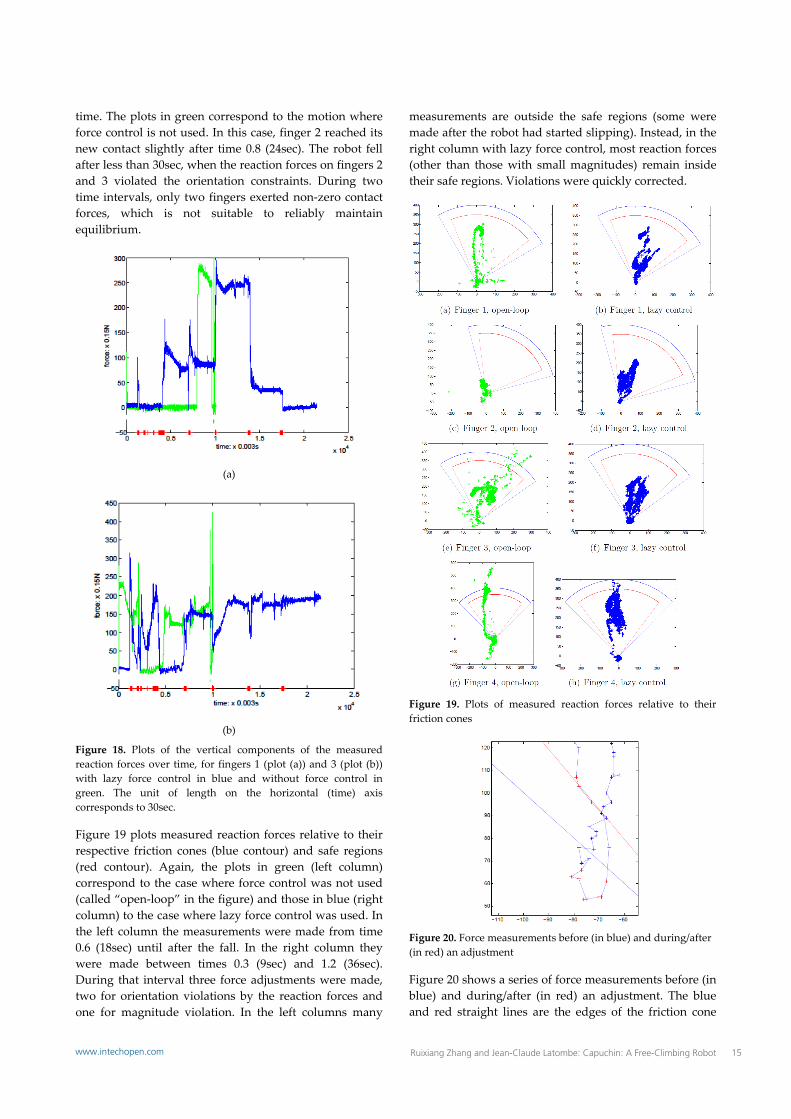
time. The plots in green correspond to the motion where force control is not used. In this case, finger 2 reached its new contact slightly after time 0.8 (24sec). The robot fell after less than 30sec, when the reaction forces on fingers 2 and 3 violated the orientation constraints. During two time intervals, only two fingers exerted non‐zero contact forces, which is not suitable to reliably maintain equilibrium.
(a)
(b)
Figure 18. Plots of the vertical components of the measured reaction forces over time, for fingers 1 (plot (a)) and 3 (plot (b)) with lazy force control in blue and without force control in green. The unit of length on the horizontal (time) axis corresponds to 30sec.
Figure 19 plots measured reaction forces relative to their respective friction cones (blue contour) and safe regions (red contour). Again, the plots in green (left column) correspond to the case where force control was not used (called “open‐loop” in the figure) and those in blue (right column) to the case where lazy force control was used. In the left column the measurements were made from time 0.6 (18sec) until after the fall. In the right column they were made between times 0.3 (9sec) and 1.2 (36sec). During that interval three force adjustments were made, two for orientation violations by the reaction forces and one for magnitude violation. In the left columns many
measurements are outside the safe regions (some were made after the robot had started slipping). Instead, in the right column with lazy force control, most reaction forces (other than those with small magnitudes) remain inside their safe regions. Violations were quickly corrected.
Figure 19. Plots of measured reaction forces relative to their friction cones
Figure 20. Force measurements before (in blue) and during/after (in red) an adjustment
Figure 20 shows a series of force measurements before (in blue) and during/after (in red) an adjustment. The blue and red straight lines are the edges of the friction cone
15Ruixiang Zhang and Jean-Claude Latombe: Capuchin: A Free-Climbing Robotwww.intechopen.com
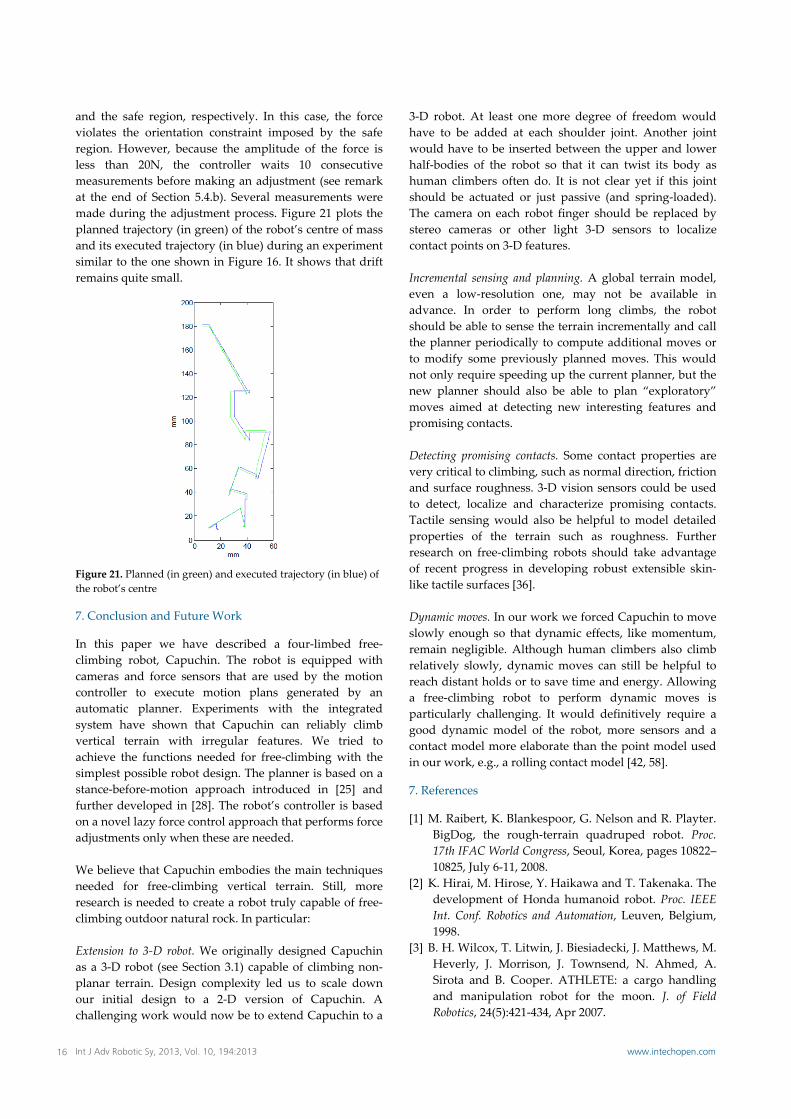
and the safe region, respectively. In this case, the force violates the orientation constraint imposed by the safe region. However, because the amplitude of the force is less than 20N, the controller waits 10 consecutive measurements before making an adjustment (see remark at the end of Section 5.4.b). Several measurements were made during the adjustment process. Figure 21 plots the planned trajectory (in green) of the robot’s centre of mass and its executed trajectory (in blue) during an experiment similar to the one shown in Figure 16. It shows that drift remains quite small.
Figure 21. Planned (in green) and executed trajectory (in blue) of the robot’s centre
7. Conclusion and Future Work
In this paper we have described a four‐limbed free‐climbing robot, Capuchin. The robot is equipped with cameras and force sensors that are used by the motion controller to execute motion plans generated by an automatic planner. Experiments with the integrated system have shown that Capuchin can reliably climb vertical terrain with irregular features. We tried to achieve the functions needed for free‐climbing with the simplest possible robot design. The planner is based on a stance‐before‐motion approach introduced in [25] and further developed in [28]. The robot’s controller is based on a novel lazy force control approach that performs force adjustments only when these are needed. We believe that Capuchin embodies the main techniques needed for free‐climbing vertical terrain. Still, more research is needed to create a robot truly capable of free‐climbing outdoor natural rock. In particular: Extension to 3‐D robot. We originally designed Capuchin as a 3‐D robot (see Section 3.1) capable of climbing non‐planar terrain. Design complexity led us to scale down our initial design to a 2‐D version of Capuchin. A challenging work would now be to extend Capuchin to a
3‐D robot. At least one more degree of freedom would have to be added at each shoulder joint. Another joint would have to be inserted between the upper and lower half‐bodies of the robot so that it can twist its body as human climbers often do. It is not clear yet if this joint should be actuated or just passive (and spring‐loaded). The camera on each robot finger should be replaced by stereo cameras or other light 3‐D sensors to localize contact points on 3‐D features. Incremental sensing and planning. A global terrain model, even a low‐resolution one, may not be available in advance. In order to perform long climbs, the robot should be able to sense the terrain incrementally and call the planner periodically to compute additional moves or to modify some previously planned moves. This would not only require speeding up the current planner, but the new planner should also be able to plan “exploratory” moves aimed at detecting new interesting features and promising contacts. Detecting promising contacts. Some contact properties are very critical to climbing, such as normal direction, friction and surface roughness. 3‐D vision sensors could be used to detect, localize and characterize promising contacts. Tactile sensing would also be helpful to model detailed properties of the terrain such as roughness. Further research on free‐climbing robots should take advantage of recent progress in developing robust extensible skin‐like tactile surfaces [36]. Dynamic moves. In our work we forced Capuchin to move slowly enough so that dynamic effects, like momentum, remain negligible. Although human climbers also climb relatively slowly, dynamic moves can still be helpful to reach distant holds or to save time and energy. Allowing a free‐climbing robot to perform dynamic moves is particularly challenging. It would definitively require a good dynamic model of the robot, more sensors and a contact model more elaborate than the point model used in our work, e.g., a rolling contact model [42, 58].
7. References
[1] M. Raibert, K. Blankespoor, G. Nelson and R. Playter. BigDog, the rough‐terrain quadruped robot. Proc. 17th IFAC World Congress, Seoul, Korea, pages 10822–10825, July 6‐11, 2008.
[2] K. Hirai, M. Hirose, Y. Haikawa and T. Takenaka. The development of Honda humanoid robot. Proc. IEEE Int. Conf. Robotics and Automation, Leuven, Belgium, 1998.
[3] B. H. Wilcox, T. Litwin, J. Biesiadecki, J. Matthews, M. Heverly, J. Morrison, J. Townsend, N. Ahmed, A. Sirota and B. Cooper. ATHLETE: a cargo handling and manipulation robot for the moon. J. of Field Robotics, 24(5):421‐434, Apr 2007.
16 Int J Adv Robotic Sy, 2013, Vol. 10, 194:2013 www.intechopen.com

[4] J. Kuffner, K., S. Kagami, M. Inaba and H. Inoue. Motion planning for humanoid robots. Proc. Int. Symp. Robotics Research, Siena, Italy, 2003.
[5] O. Kanoun, J.P. Laumond and E. Yoshida. Planning foot placement for a humanoid robot: A problem of inverse kinematics, Int. J. of Robotics Research, 30(4):476‐485, 2011.
[6] H. Lee, Y. Shen, C. Yu, G. Singh and A. Y. Ng. Quadruped robot obstacle negotiation via reinforcement learning. Proc. IEEE Int. Conf. Robotics and Automation, 2006.
[7] M. Abderrahim, C. Balaguer, A. Gimenez, J.M. Pastor and V.M. Padron. ROMA: A climbing robot for inspection operations. Proc. IEEE Int. Conf. Robotics and Automation, Detroit, MI, 1999.
[8] H. Amano. A vertically moving robot able to grip handrails for fire‐fighting. Advanced Robotics, 16(6):557‐560, 2002.
[9] D. Bevly, S. Dubowsky and C. Mavroidis. A simplified Cartesian computed torque controller for highly geared systems and its application to an experimental climbing robot. ASME J. of Dynamic Systems, Measurement and Control, 122(1):27‐32, 2000.
[10] D. Bevly, S. Farritor and S. Dubowsky. Action module planning and its application to an experimental climbing robot. Proc. IEEE Int. Conf. Robotics and Automation, San Francisco, CA, vol. 4, pages 4009‐4014, 2000.
[11] S. Hirose, A. Nagabuko and R. Toyama. Machine that can walk and climb on floors, walls, and ceilings. Proc. IEEE Int. Conf. Robotics and Automation, Pisa, Italy, pages 753‐758, 1991.
[12] Z.M. Ripin, B.S. Tan, A.B. Abdullah and Z. Samad. Development of a lowcost modular pole climbing robot. Proc. IEEE TENCON, Vol. 1, pages 196‐200, Kuala Lumpur, Malaysia, 2000.
[13] Y. Xu, H.B. Brown, M. Friendman and T. Kanade. Control system of the self‐mobile space manipulator. IEEE Tr. on Control Systems Technology, 2(3):207‐219, 1994.
[14] M. Yim, S. Homans and K. Roufas. Climbing with snake‐robots. Proc. IFAC Workshop Mobile Robot Technology, Jejudo, Korea, 2001.
[15] F.W. Bach, H. Haferkamp, J. Lindemaier and M. Rachkov. Underwater climbing robot for contact arc metal drilling and cutting. Proc. IEEE Int. Conf. Industrial Electronics, Control and Instrumentation, Taipei, Taiwan, pages 1560‐1565, 1996.
[16] L. Briones, P. Bustamante and M. A. Serna. Wall‐climbing robot for inspection in nuclear power plants. Proc. IEEE Int. Conf. Robotics and Automation, San Diego, CA, pages 1409‐1414, 1994.
[17] I.M. Chen and S.H. Yeo. Locomotion of a two‐dimensional walking climbing robot using a closed‐loop mechanism: From gait generation to navigation. Int. J. of Robotics Research, 22(1):21‐40, 2003.
[18] T. Kang, H. Kim, T. Son and H. Choi. Design of quadruped walking and climbing robot. Proc. IEEE/RSJ Int. Conf. Intelligent Robots and Systems, Las Vegas, NV, 2003.
[19] S. Kim, M. Spenko, S. Trujilo, B. Yeyneman, V. Mattoli and M. Cutkosky. Whole body adhesion: hierarchical, directional and distributed control of adhesive forces for a climbing robot. Proc. IEEE Int. Conf. Robotics and Automation, pages 1268‐1273, April 2007.
[20] A.T. Asbeck, S. Kim and M.R. Cutkosky. Scaling hard vertical surfaces with compliant microspine arrays. Int. J. of Robotics Research, 25(12):1165‐1179, 2006.
[21] W. Neubauer. A spider‐like robot that climbs vertically in ducts or pipes. Proc. IEEE/RSJ Int. Conf. Intelligent Robots and Systems, Munich, Germany, pages 1178‐1185, 1994.
[22] T. Robmann and F. Pfeiffer. Control of an eight legged pipe crawling robot. Proc. Int. Symp. Experimental Robotics, pages 353‐346, 1997.
[23] A. Zagler and F. Pfeiffer. MORITZ a pipe crawler for tube junctions. IEEE Int. Conf. Robotics and Automation, Taipei, Taiwan, pages 2954‐2959, 2003.
[24] B. Kennedy, A. Okon, H. Aghazarian, et al. Lemur IIb: a robotic system for steep terrain access. Industrial Robot: An International J., 33(4):265‐269, Emerald Publishing, 2006.
[25] S.P. Linder, E. Wei, A. Clay. Robotic rock climbing using computer vision and force feedback. Proc. IEEE Int. Conf. Robotics and Automation, pages 4685‐4690, 2005.
[26] T. Bretl, S. Rock, J.C. Latombe, B. Kennedy and H. Aghazarian. Free‐climbing with a multi‐use robot. Proc. 9th Int. Symp. Experimental Robotics, Singapore, June 2004.
[27] T. Bretl. Multi‐step motion planning: application to free‐climbing robots. Ph.D Diss., Dept. of Aero & Astronautics, Stanford University, Stanford, CA, June 2005.
[28] K. Hauser. Motion planning for legged and humanoid robots. Ph.D. Diss., Dept. of Computer Science, Stanford University, Stanford, CA, September 2008.
[29] T. Bretl, T. Miller, S.M. Rock and J.C. Latombe. Climbing robots in natural terrain. Proc. 7th Int. Symp. Artificial Intelligence, Robotics and Automation in Space, Nara, Japan, May 2003.
[30] T. Bretl, S.M. Rock and J.C. Latombe. Motion planning for a three‐limbed climbing robot in vertical natural terrain. Proc. IEEE Int. Conf. Robotics and Automation, Taipei, Taiwan, vol. 3, pages 2946‐2953, 2003.
[31] T. Bretl. Motion planning of multi‐limbed robots subject to equilibrium constraints: the free‐climbing robot problem. Int. J. of Robotics Research, 25(4):317‐342, 2006.
17Ruixiang Zhang and Jean-Claude Latombe: Capuchin: A Free-Climbing Robotwww.intechopen.com

[32] K. Hauser, T. Bretl, J.C. Latombe, Learning‐Assisted Multi‐Step Planning. Proc. IEEE Intl. Conf. Robotics and Automation, Barcelona, Spain, 2005
[33] K. Hauser and J.C. Latombe. Multi‐modal motion planning in non‐expansive spaces. Int. J. of Robotics Research, 29(7):897‐915, 2010.
[34] T. G. Miller, T. Bretl and S. Rock. Control of a climbing robot using real‐time convex optimization. Proc. IFAC Symposium Mechatronic Systems, Heidelberg, Germany, September 2006.
[35] T. G. Miller. Control of a climbing robot using real‐time convex optimization. Ph.D Thesis, Dept. of Aero & Astronautics, Stanford University, Stanford, CA, December 2007.
[36] D.J. Lipomi, M. Vosgueritchian, B.C.K. Tee, S. L. Hellstrom, J.A. Lee, C.H. Fox and Z. Bao. Skin‐like pressure and strain sensors based on transparent elastic films of carbon nanotubes. Nature Nanotechnology, 6:788–792, 2011.
[37] K. Hauser, T. Bretl, J.C. Latombe, K. Harada and B. Wilcox, Motion planning for legged robots on varied terrain. Int. J. of Robotics Research, 27(11‐12):1325‐1349, 2008.
[38] D. Hsu. Randomized single‐query motion planning in expansive spaces. Ph.D. Thesis, Dept. of Computer Science, Stanford University, Stanford, CA, 2000.
[39] L.E. Kavraki, P. Svestka, J.C. Latombe and M. Overmars. Probabilistic roadmaps for path planning in high‐dimensional configuration spaces. IEEE Tr. Robotics and Automation, 12(4):566‐580, 1996.
[40] M. Saha. Motion planning with probabilistic roadmaps. Ph.D. Thesis, Dept. of Mechanical Engineering, Stanford University, Stanford, CA, 2006.
[41] G. Sanchez. Single‐query bi‐directional probabilistic roadmap planner with lazy collision checking. Ph.D. Thesis, ITESM Campus Cuernavaca, Mexico, 2002.
[42] A. Bicchi and V. Kumar. Robotic grasping and contact: a review. Proc. IEEE Int. Conf. Robotics and Automation, San Francisco, CA, vol. 1, pages 348‐353, 2000.
[43] K. Hashimoto. A review on vision‐based control of robot manipulators. Advanced Robotics, 17(10):969‐991, 2003.
[44] S. Hutchinson, G.D. Hager and P.I. Corke. A Tutorial on Visual Servo Control. IEEE Tr. Robotics and Automation, 12(5):651‐670, 1996.
[45] A. Leeper, K. Hsiao, E. Chu and K. Salisbury. Using near‐field stereo vision for robotic grasping in
cluttered environments. Proc. Int. Symp. Experimental Robotics, New Delhi, India, Dec. 2010.
[46] A. Saxena, J. Driemeyer and A.Y. Ng. Robotic grasping of novel objects using vision. Int. J. of Robotics Research, 27(2):157–173, 2008.
[47] N. Hogan. Impedance control: an approach to manipulation. Part I: Theory. Part II: Implementation. Part III: Applications. ASME J. of Dynamic Systems, Measurement, and Control, 107:1‐24, 1985.
[48] M. Mason. Compliance and force control for computer controlled manipulators. IEEE Tr. on Systems, Man and Cybernetics, SMC‐11:418‐432, 1981.
[49] S. P. Patarinski and R. G. Botev. Robot force control: a review. Mechatronics, 3(4): 377‐398, 1993.
[50] M. Raibert and J.J. Craig. Hybrid position/force control of manipulators. ASME J. of Dynamic Systems, Measurement, and Control, 102:126‐133, 1981.
[51] J.K. Salisbury. Active stiffness control of a manipulator in Cartesian coordinates. Proc. 19th 1EEE Conf. Decision and Control, 1980.
[52] D. Whitney. Force feedback control of manipulator fine motions. ASME J. of Dynamic Systems, Measurement, and Control, 98:91‐97, 1977.
[53] Y. Chen, I. Walker and J. Cheatham. A new approach to force distribution and planning for multi‐fingered grasps of solid objects. Proc. IEEE Conf. Robotics and Automation, Sacramento, CA, pages 890‐896, April 1991.
[54] T. Schlegl, M. Buss, T. Omata and G. Schmidt. Fast dextrous regrasping with optimal contact forces and contact sensor‐based impedance control. IEEE Int. Conf. Robotics and Automation, pages 103‐108, 2001.
[55] L. Sentis and O. Khatib. Synthesis of whole‐body behaviors through hierarchical control of behavioral primitives. Int. J. of Humanoid Robotics, 2(4):505‐518, December 2005.
[56] Y. Nakamura. Minimizing object strain energy for coordination of multiple robotic mechanisms. Proc. American Control Conf., pages 499‐504, 1998.
[57] R. Zhang. Design and implementation of an autonomous climbing robot. PhD Thesis, Computer Science Department, Stanford University, March 2012.
[58] Z. Li, J. Canny and S. Sastry. On motion planning for dextrous manipulation, part I: The problem formulation. Proc. IEEE Int. Conf. Robotics and Automation, pages 775‐780, 1989.
18 Int J Adv Robotic Sy, 2013, Vol. 10, 194:2013 www.intechopen.com


![Design and Implementation of an Autonomous Climbing Robot [1]ai.stanford.edu/~rxzhang/Capuchin Climbing Robot.pdf · Control of A Climbing Robot Using Real-time Convex Optimization](https://img.pdfslide.us/doc/110x75/5e53900385cc1170eb34bd01/design-and-implementation-of-an-autonomous-climbing-robot-1ai-rxzhangcapuchin.jpg)