Embed Size (px)
Citation preview

Capillary Two-Phase Thermal Devices for Space Applications
Jentung KuNASA/ Goddard Space Flight Center
Greenbelt, Maryland
April 2016
https://ntrs.nasa.gov/search.jsp?R=20160004212 2018-07-23T20:03:30+00:00Z
Outline
• Introduction• Heat Pipe Operating Principles
– Pressure DropsPressure Drops– Operating Temperature
• Heat Pipe Operating Characteristics• Loop Heat Pipe Operating Principles
– Pressure Drops– Operating Temperature
• Loop Heat Pipe Operating Characteristics• Examples of Space Applications
2Capillary Two-Phase Thermal Devices - Ku 2016
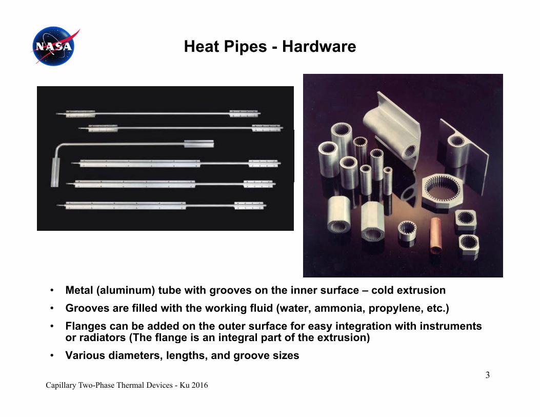
Heat Pipes - Hardware
M t l ( l i ) t b ith th i f ld t i• Metal (aluminum) tube with grooves on the inner surface – cold extrusion• Grooves are filled with the working fluid (water, ammonia, propylene, etc.)• Flanges can be added on the outer surface for easy integration with instruments
or radiators (The flange is an integral part of the extrusion)
3
or radiators (The flange is an integral part of the extrusion)• Various diameters, lengths, and groove sizes
Capillary Two-Phase Thermal Devices - Ku 2016
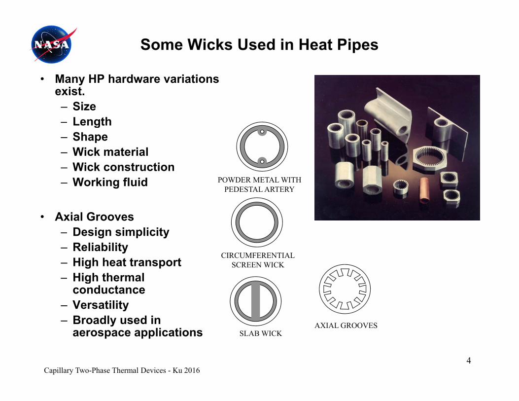
Some Wicks Used in Heat Pipes
• Many HP hardware variations exist.– Size– LengthLength– Shape– Wick material– Wick construction
POWDER METAL WITHPEDESTAL ARTERY
– Working fluid
• Axial Grooves
CIRCUMFERENTIALSCREEN WICK
– Design simplicity– Reliability– High heat transport
High thermal
AXIAL GROOVES
– High thermal conductance
– Versatility– Broadly used in
Capillary Two-Phase Thermal Devices - Ku 20164
SLAB WICKAXIAL GROOVES
aerospace applications
Introduction – Why Heat Pipes?
• Heat pipe is a capillary two-phase heat transfer device.– Transports heat from a heat source to a heat sink– Works as an isothermalizer
• Why two-phase thermal system?– Efficient heat transfer – boiling and condensationEfficient heat transfer boiling and condensation– Small temperature difference between the heat source and
heat sink
• Why capillary two-phase system? – Passive – no external pumping power
S lf l ti fl t l d i– Self regulating – no flow control devices– No moving parts – vibration free
5Capillary Two-Phase Thermal Devices - Ku 2016
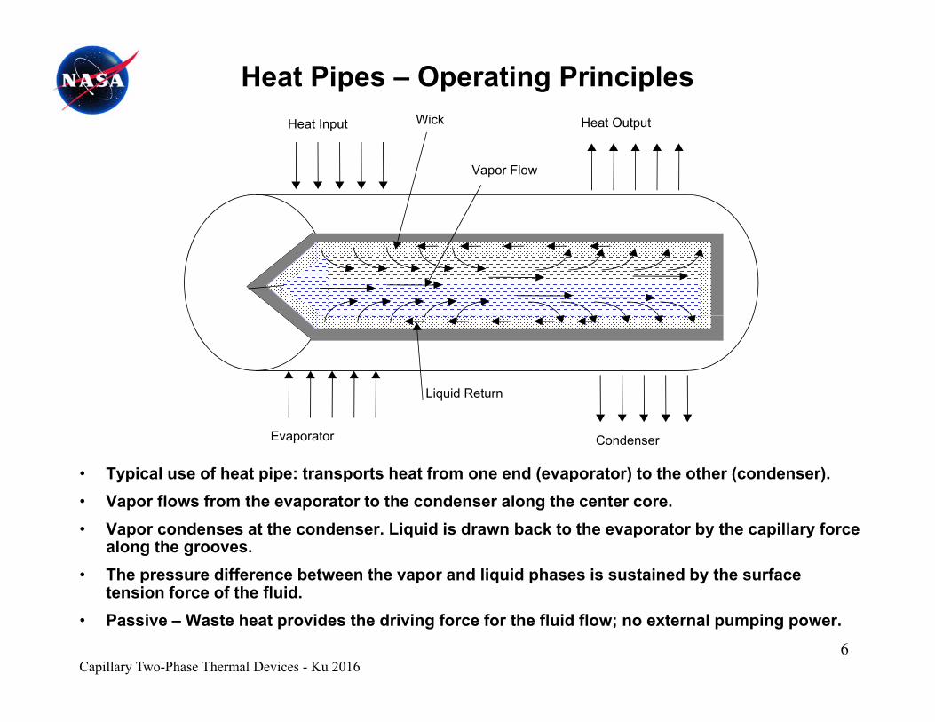
Heat Pipes – Operating PrinciplesHeat OutputHeat Input Wick
Vapor Flow
Liquid Return
• Typical use of heat pipe: transports heat from one end (evaporator) to the other (condenser).V fl f th t t th d l th t
Evaporator Condenser
• Vapor flows from the evaporator to the condenser along the center core.• Vapor condenses at the condenser. Liquid is drawn back to the evaporator by the capillary force
along the grooves.• The pressure difference between the vapor and liquid phases is sustained by the surface
t i f f th fl id
Capillary Two-Phase Thermal Devices - Ku 20166
tension force of the fluid.• Passive – Waste heat provides the driving force for the fluid flow; no external pumping power.
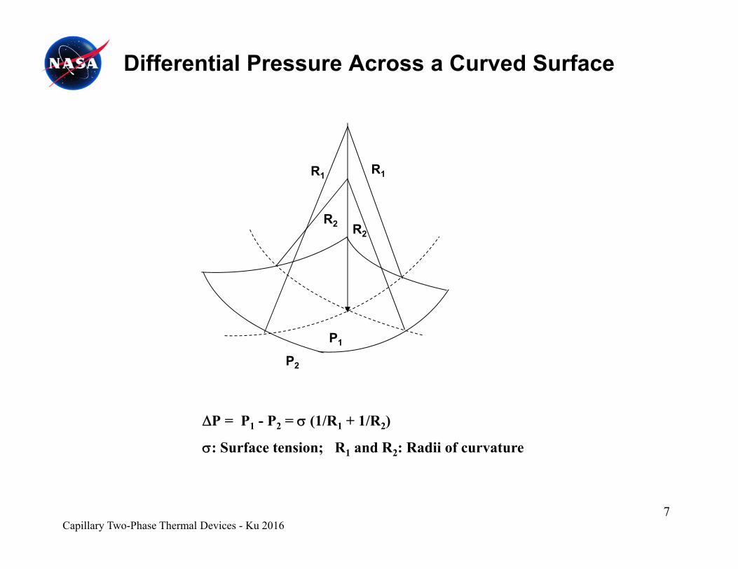
Differential Pressure Across a Curved Surface
R1R1
R2 R2
1
P1
P2
P = P1 - P2 = (1/R1 + 1/R2)
: Surface tension; R1 and R2: Radii of curvature
7Capillary Two-Phase Thermal Devices - Ku 2016
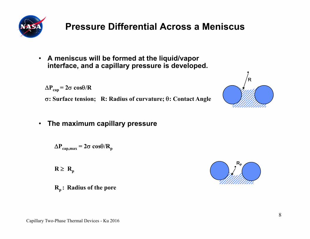
Pressure Differential Across a Meniscus
• A meniscus will be formed at the liquid/vapor interface, and a capillary pressure is developed.
Pcap = 2 cos/R
: Surface tension; R: Radius of curvature; : Contact Angle
RR
• The maximum capillary pressure
RRPP
Pcap,max = 2 cos/Rp
PPR Rp
Rp : Radius of the pore
Capillary Two-Phase Thermal Devices - Ku 20168
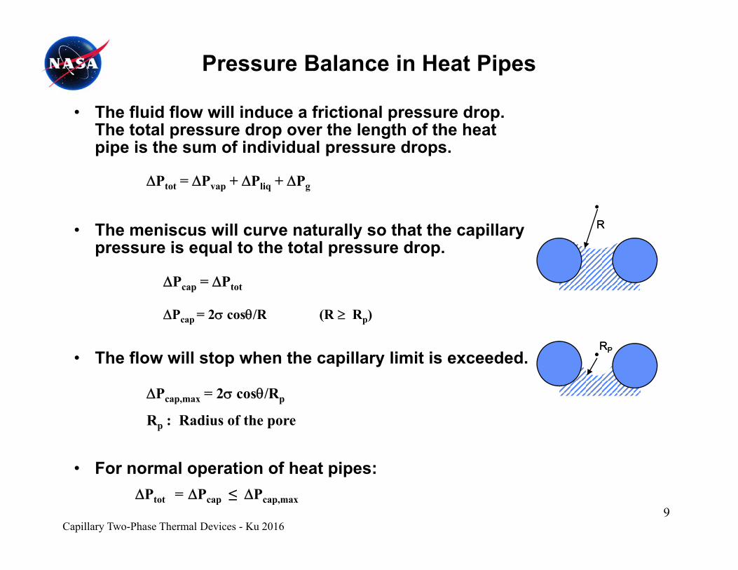
Pressure Balance in Heat Pipes
• The fluid flow will induce a frictional pressure drop. The total pressure drop over the length of the heat pipe is the sum of individual pressure drops.
P P + P + P
• The meniscus will curve naturally so that the capillary pressure is equal to the total pressure drop
Ptot = Pvap + Pliq + Pg
RR
pressure is equal to the total pressure drop.
Pcap = Ptot
Pcap = 2 cos/R (R Rp)
• The flow will stop when the capillary limit is exceeded.RRPP
P = 2 cos/R
cap ( p)
For normal operation of heat pipes
Pcap,max = 2 cos/Rp
Rp : Radius of the pore
Capillary Two-Phase Thermal Devices - Ku 20169
• For normal operation of heat pipes:Ptot = Pcap ≤ Pcap,max
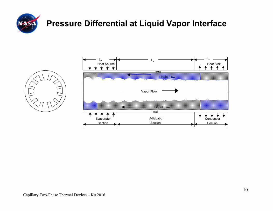
Pressure Differential at Liquid Vapor Interface
Heat SinkHeat SourceLe La
Lc
Liquid Flowwall
Vapor Flow
wallLiquid Flow
Evaporator CondenserAdiabatic
Vapor Flow
EvaporatorSection
CondenserSection
AdiabaticSection
Capillary Two-Phase Thermal Devices - Ku 201610
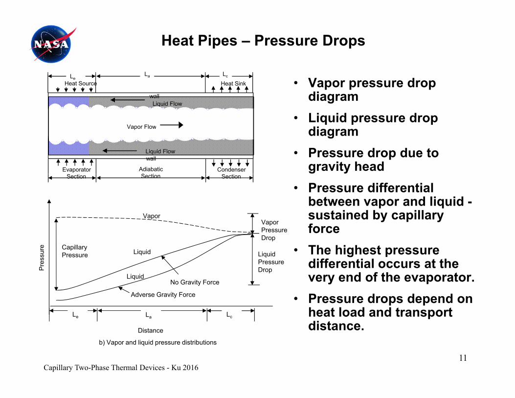
Heat Pipes – Pressure Drops
L L
Liquid Flow
Heat SinkHeat Source
wall
LeLa Lc
• Vapor pressure drop diagram
• Liquid pressure drop
wallLiquid Flow
Evaporator CondenserAdiabaticS ti
Vapor Flowq p p
diagram• Pressure drop due to
gravity head
VaporVapor
Section SectionSection
• Pressure differential between vapor and liquid -sustained by capillary f
LiquidPressure DropPr
essu
re CapillaryPressure
VaporPressure Drop
Liquid
Li id
force• The highest pressure
differential occurs at the d f th t
Le La Lc
LiquidNo Gravity Force
Adverse Gravity Force
very end of the evaporator.• Pressure drops depend on
heat load and transport distance
Capillary Two-Phase Thermal Devices - Ku 201611
Distance
b) Vapor and liquid pressure distributions
distance.

Heat Pipes - Heat Transport Limit
L L • The total pressure drop must not exceed its capillary pressure head.
Ptot = Pvap+ Pliq + Pg
Pcap,max = cos/Rp
Liquid Flow
Heat SinkHeat Source
wall
LeLa Lc
Ptot ≤ Pcap,max
• Heat Transport Limit– (QL)max = QmaxLeff
– Leff = 0.5 Le + La + 0.5 Lc
wallLiquid Flow
Evaporator CondenserAdiabaticS ti
Vapor Flow
VaporVapor
Leff 0.5 Le La 0.5 Lc
– (QL)max measured in watt-inches or watt-meters
• Capillary pressure head:
Section SectionSection
LiquidPressure DropPr
essu
re CapillaryPressure
VaporPressure Drop
Liquid
Li id
Pcap 1/ Rp
• Liquid pressure drop:
Pliq 1/ Rp2
A ti l di i t f
Le La Lc
LiquidNo Gravity Force
Adverse Gravity Force
• An optimal pore radius exists for maximum heat transport.
• Limited pumping head against gravity
Capillary Two-Phase Thermal Devices - Ku 201612
Distance
b) Vapor and liquid pressure distributions
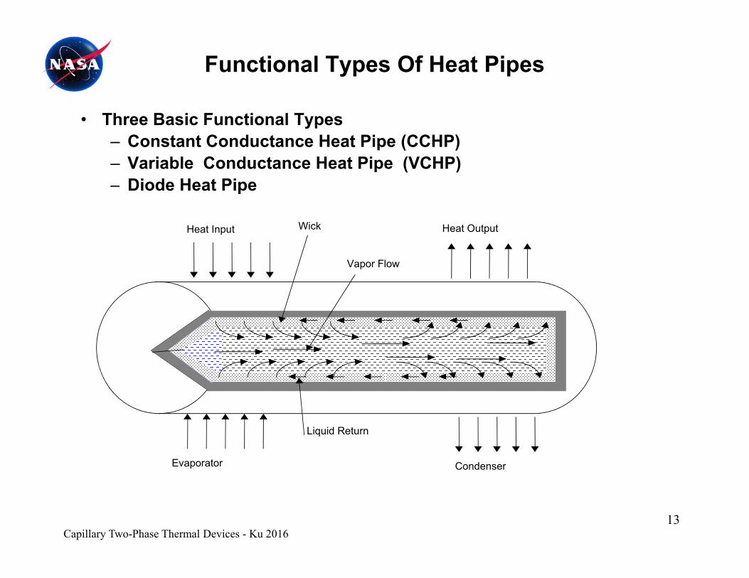
Functional Types Of Heat Pipes
• Three Basic Functional Types– Constant Conductance Heat Pipe (CCHP)– Variable Conductance Heat Pipe (VCHP)
Di d H t Pi– Diode Heat Pipe
Heat OutputHeat Input Wick
Vapor Flow
Evaporator Condenser
Liquid Return
Capillary Two-Phase Thermal Devices - Ku 201613
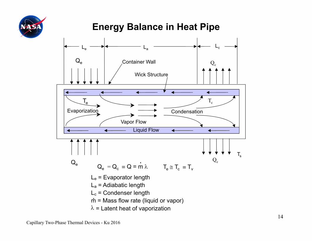
Energy Balance in Heat Pipe
L
Wick Structure
Container WallQe
Le LaLc
Qc
Wick Structure
Te Tc
Liquid FlowVapor Flow
CondensationEvaporization
Q = Q Q = m
Ts
QeQc
T T T.
Qe = Qc Q = m
Le = Evaporator lengthLa = Adiabatic lengthLc = Condenser length
Te Tc Tv
Capillary Two-Phase Thermal Devices - Ku 201614
m = Mass flow rate (liquid or vapor) = Latent heat of vaporization
.
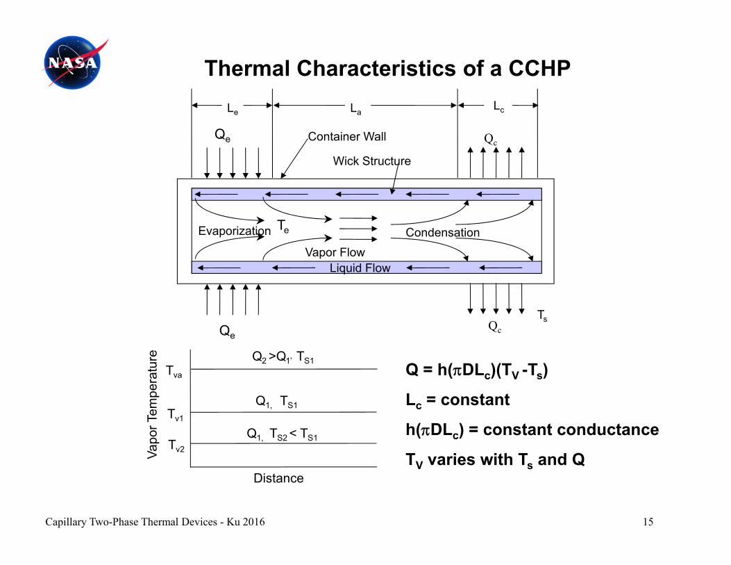
Thermal Characteristics of a CCHPL L L
Wick Structure
Container WallQe
Le LaLc
Qc
CondensationEvaporization Te
Liquid FlowVapor Flow
Ts
Tva
Q2 >Q1’ TS1
erat
ure
Q = h(DLc)(TV -Ts)
Ts
QeQc
Tv1
Tv2
Q1, TS1
Q1, TS2 < TS1
Vapo
r Tem
pe Lc = constant
h(DLc) = constant conductance
T varies with T and Q
15
DistanceTV varies with Ts and Q
Capillary Two-Phase Thermal Devices - Ku 2016

Thermal Characteristics of a VCHP
Gas Reservoir
Effective Condenser
Evaporator
Active Portion of Heat Pipe
Adiabatic Section Condenser
Q = h(DLc)(TV -Ts)Lc varies with Ts and Qso as to keep T constantNon-Condensable
Effective Condenser
Vapor Flow so as to keep TV constanth(DLc) = variable conductance
Reservoir size is a function of:H t I t H t O t t
Gas Front
gasVapor Flow
• Range of heat load• Range of sink temperature• Temperature control requirement
Temperature
TTv1
Positions of gas front
Heat Input Heat Output
requirement
Distance
Heat-sinktemperature
Tv2
Tv3Q3 Q2
Q1
16
DistanceEvaporator Adiabatic
sectionCondenser Gas
reservoir
Capillary Two-Phase Thermal Devices - Ku 2016
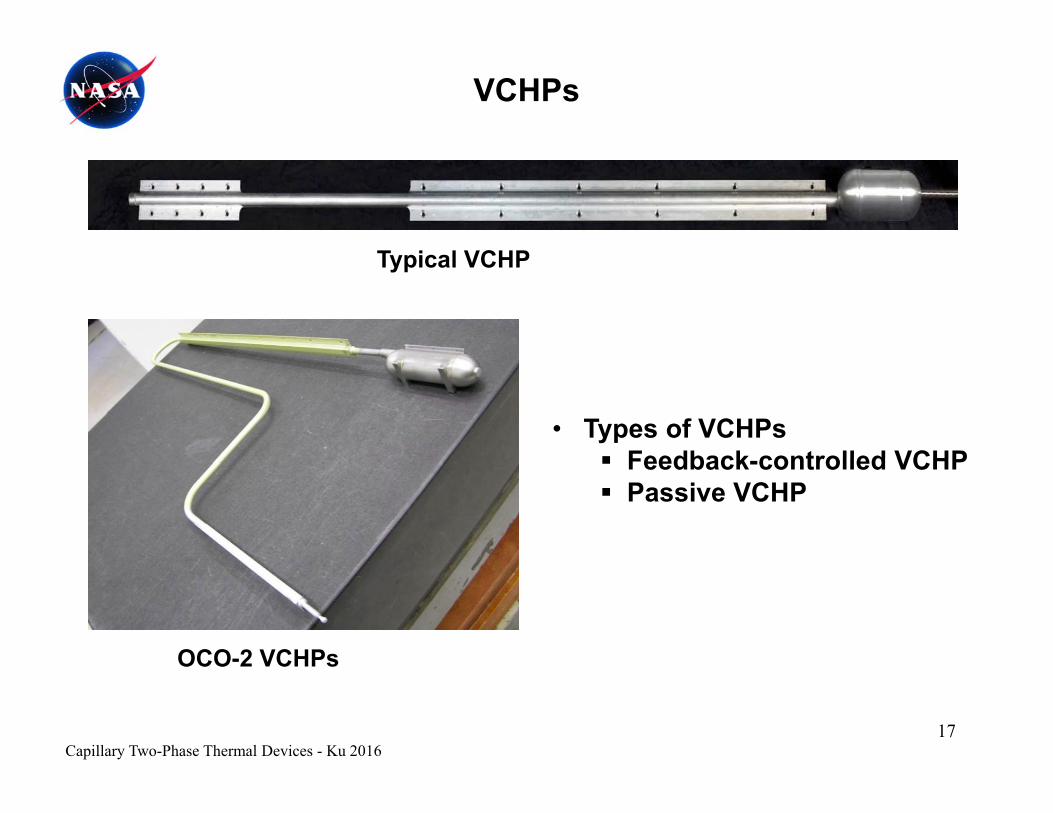
VCHPs
T i l VCHPTypical VCHP
• Types of VCHPs Feedback controlled VCHP Feedback-controlled VCHP Passive VCHP
OCO-2 VCHPs
Capillary Two-Phase Thermal Devices - Ku 201617
OCO 2 VCHPs
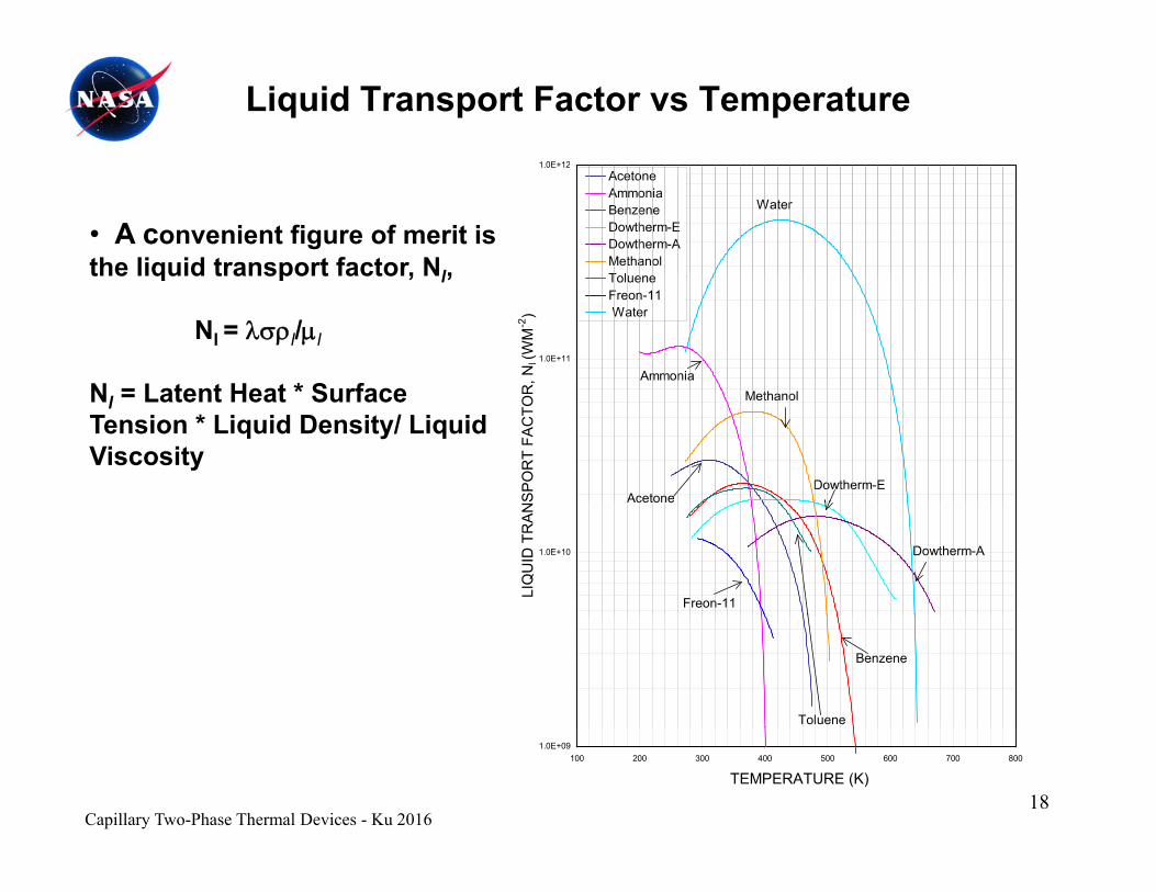
Liquid Transport Factor vs Temperature1 0E+121.0E+12
AcetoneAmmoniaBenzeneDowtherm-EDowtherm-AMethanolToluene
Water
• A convenient figure of merit is the liquid transport factor, Nl,
1.0E+11
R, N
l (W
M-2
)
TolueneFreon-11 Water
Ammonia
q p , l,
Nl = l/l
N = Latent Heat * Surface
SP
OR
T FA
CTO
R
AcetoneDowtherm-E
MethanolNl = Latent Heat * Surface Tension * Liquid Density/ Liquid Viscosity
1.0E+10
LIQ
UID
TR
AN
Freon-11
ceto e
Dowtherm-A
Toluene
Benzene
18
1.0E+09100 200 300 400 500 600 700 800
TEMPERATURE (K)
Capillary Two-Phase Thermal Devices - Ku 2016

Heat Pipe Performance Curve for Given Heat Pipe Design and Working Fluid (Usually Provided by the Vendor)
30300
TRANSPORT CAPABILITY VS. TEMPERATURE DIE 16692, Single Sided Heat Pipe, Ammonia Fluid
236.6224.3
20
25
200
250
m)(W
-m)
0-g
15
20
150
200
Stat
ic H
eigh
t (m
m
spor
t Cap
abili
ty g
- 2.54 mm
5
10
50
100
S
Max
Tra
ns Static Height
00-60 -50 -40 -30 -20 -10 0 10 20 30 40 50 60 70 80
Temperature (°C)Temperature ( C)
19Capillary Two-Phase Thermal Devices - Ku 2016

Heat Pipes - Heat Transport Limit• The total pressure drop must not
L L exceed its capillary pressure head.Ptot = Pvap+ Pliq + Pg
Pcap,max = cos/Rp
Ptot ≤ Pcap,max
Liquid Flow
Heat SinkHeat Source
wall
LeLa Lc
• Heat Transport Limit– (QL)max = QmaxLeff
– Leff = 0.5 Le + La + 0.5 Lc
– (QL) measured in watt-incheswallLiquid Flow
Evaporator CondenserAdiabaticS ti
Vapor Flow
VaporVapor
(QL)max measured in watt-inches or watt-meters
• Capillary pressure head:
Pcap 1/ Rp
Section SectionSection
LiquidPressure DropPr
essu
re CapillaryPressure
VaporPressure Drop
Liquid
Li id
• Liquid pressure drop:
Pliq 1/ Rp2
• An optimal pore radius exists for i h t t t
Le La Lc
LiquidNo Gravity Force
Adverse Gravity Force
maximum heat transport.
• Limited heat transport capability
• Limited pumping head against gravity
20
Distance
b) Vapor and liquid pressure distributions
Capillary Two-Phase Thermal Devices - Ku 201620
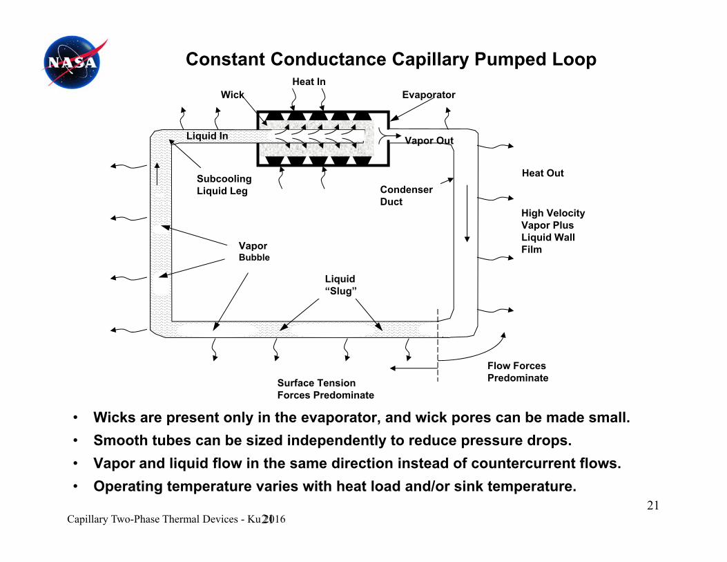
EvaporatorWickHeat In
Constant Conductance Capillary Pumped Loop
S
Vapor Out
Heat Out
Liquid In
Vapor
SubcoolingLiquid Leg Condenser
Duct
Heat Out
High VelocityVapor PlusLiquid WallFilVapor
Bubble
Liquid“Slug”
Film
Flow ForcesPredominateSurface Tension
Forces Predominate
• Wicks are present only in the evaporator, and wick pores can be made small.• Smooth tubes can be sized independently to reduce pressure drops.
V d li id fl i th di ti i t d f t t fl• Vapor and liquid flow in the same direction instead of countercurrent flows.• Operating temperature varies with heat load and/or sink temperature.
21Capillary Two-Phase Thermal Devices - Ku 201621
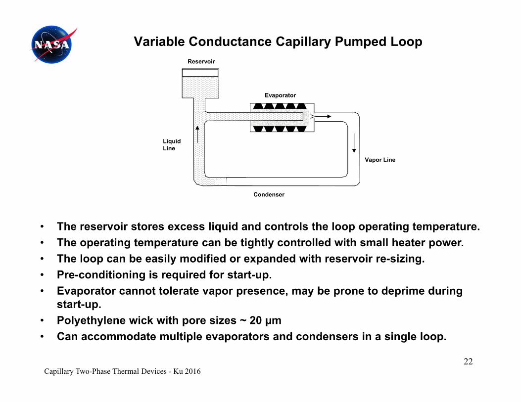
Variable Conductance Capillary Pumped Loop Reservoir
Evaporator
Liquid Line
Vapor Line
• The reservoir stores excess liquid and controls the loop operating temperature
Condenser
• The reservoir stores excess liquid and controls the loop operating temperature.• The operating temperature can be tightly controlled with small heater power. • The loop can be easily modified or expanded with reservoir re-sizing.• Pre-conditioning is required for start-up.Pre conditioning is required for start up.• Evaporator cannot tolerate vapor presence, may be prone to deprime during
start-up.• Polyethylene wick with pore sizes ~ 20 µm• Can accommodate multiple evaporators and condensers in a single loop.
Capillary Two-Phase Thermal Devices - Ku 201622
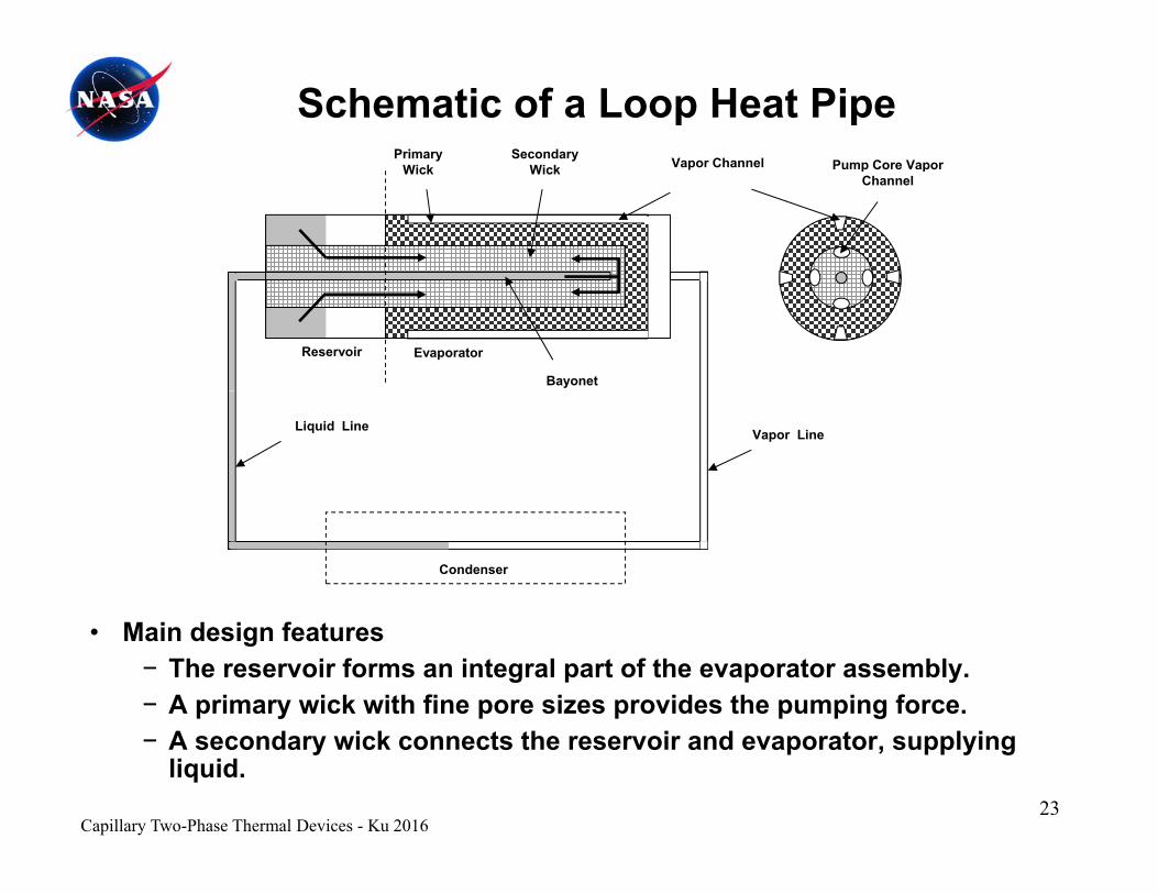
Schematic of a Loop Heat PipePrimary
Wi kSecondary
Wi k Vapor Channel Pump Core VaporWick Wick Vapor Channel Pump Core Vapor Channel
Bayonet
Reservoir Evaporator
Vapor LineLiquid Line
Condenser
• Main design features− The reservoir forms an integral part of the evaporator assembly.− A primary wick with fine pore sizes provides the pumping force.− A secondary wick connects the reservoir and evaporator, supplying
liquid. 23
Capillary Two-Phase Thermal Devices - Ku 2016
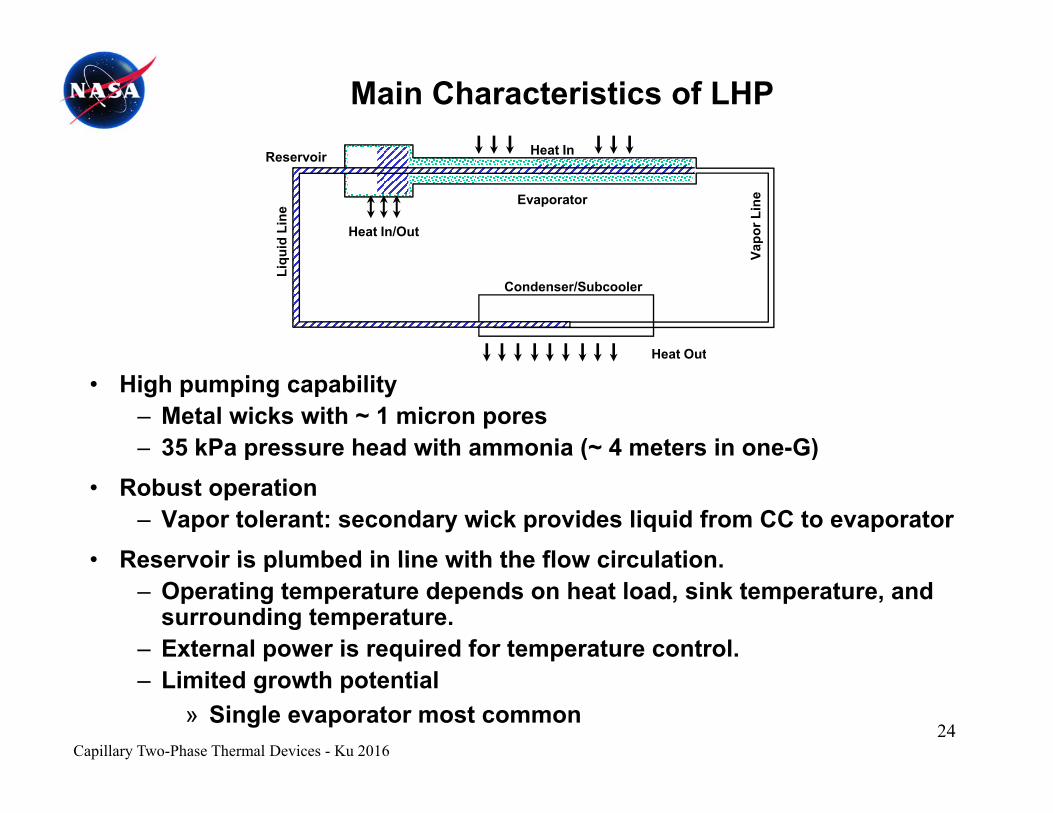
Main Characteristics of LHPHeat In
Vapo
r Lin
e
uid
Line
Evaporator
Heat In/Out
Reservoir Heat In
Condenser/Subcooler
V
Liqu
Heat Out
• High pumping capability– Metal wicks with ~ 1 micron pores– 35 kPa pressure head with ammonia (~ 4 meters in one-G)
Heat Out
p ( )• Robust operation
– Vapor tolerant: secondary wick provides liquid from CC to evaporator• Reservoir is plumbed in line with the flow circulation• Reservoir is plumbed in line with the flow circulation.
– Operating temperature depends on heat load, sink temperature, and surrounding temperature.
– External power is required for temperature control.– Limited growth potential
» Single evaporator most commonCapillary Two-Phase Thermal Devices - Ku 2016
24
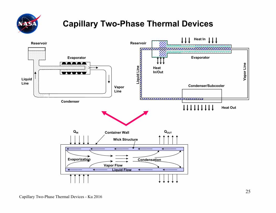
Capillary Two-Phase Thermal DevicesHeat In
Reservoir
Evaporator
nee
Evaporator
ReservoirHeat In
Liquid Line
Vapor Line
Condenser/Subcooler
Vapo
r Lin
Liqu
id L
ine Heat
In/Out
Condenser
Heat Out
Wick Structure
Container Wall QOUTQIN
Liquid FlowVapor Flow
CondensationEvaporization
Capillary Two-Phase Thermal Devices - Ku 201625
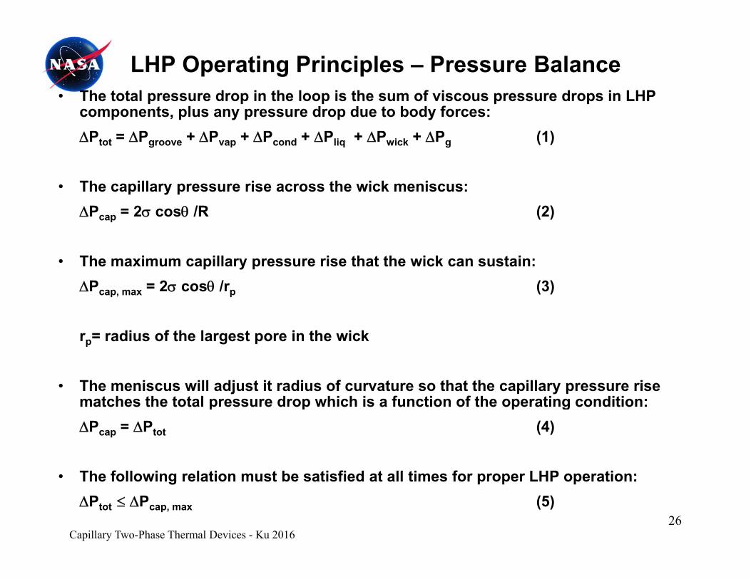
• The total pressure drop in the loop is the sum of viscous pressure drops in LHP t l d d t b d f
LHP Operating Principles – Pressure Balance
components, plus any pressure drop due to body forces:Ptot = Pgroove + Pvap + Pcond + Pliq + Pwick + Pg (1)
• The capillary pressure rise across the wick meniscus: Pcap = 2 cos /R (2)
• The maximum capillary pressure rise that the wick can sustain: Pcap, max = 2 cos /rp (3)
rp= radius of the largest pore in the wick
• The meniscus will adjust it radius of curvature so that the capillary pressure rise matches the total pressure drop which is a function of the operating condition:matches the total pressure drop which is a function of the operating condition: Pcap = Ptot (4)
Th f ll i l ti t b ti fi d t ll ti f LHP ti• The following relation must be satisfied at all times for proper LHP operation:Ptot Pcap, max (5)
Capillary Two-Phase Thermal Devices - Ku 201626
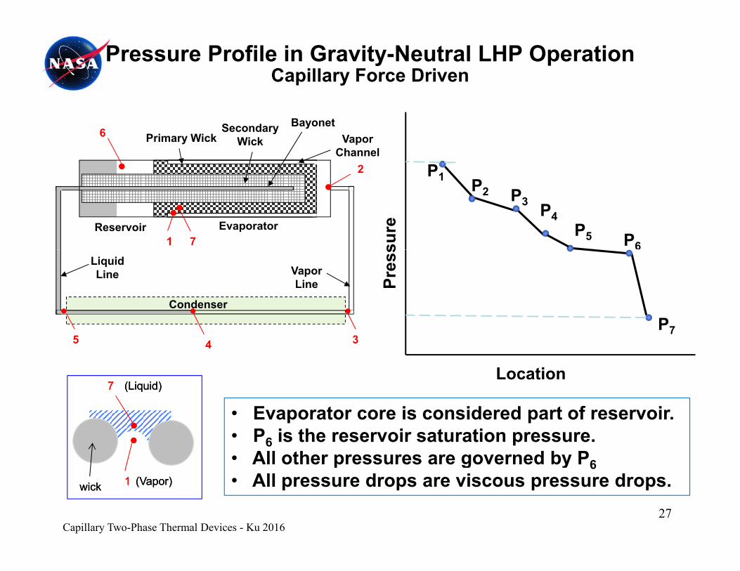
Pressure Profile in Gravity-Neutral LHP Operation Capillary Force Driven
P1
Vapor Channel
Primary WickSecondary
WickBayonet
2
6
1 P2 P3 P4P5 P6su
reReservoir Evaporator1 7
Pres
s
P
Vapor Line
Liquid Line
Condenser
Location
P7
77 (Liquid)(Liquid)
35 4
• Evaporator core is considered part of reservoir.• P6 is the reservoir saturation pressure.• All other pressures are governed by P6
p g y 6• All pressure drops are viscous pressure drops.11wickwick (Vapor)(Vapor)
Capillary Two-Phase Thermal Devices - Ku 201627
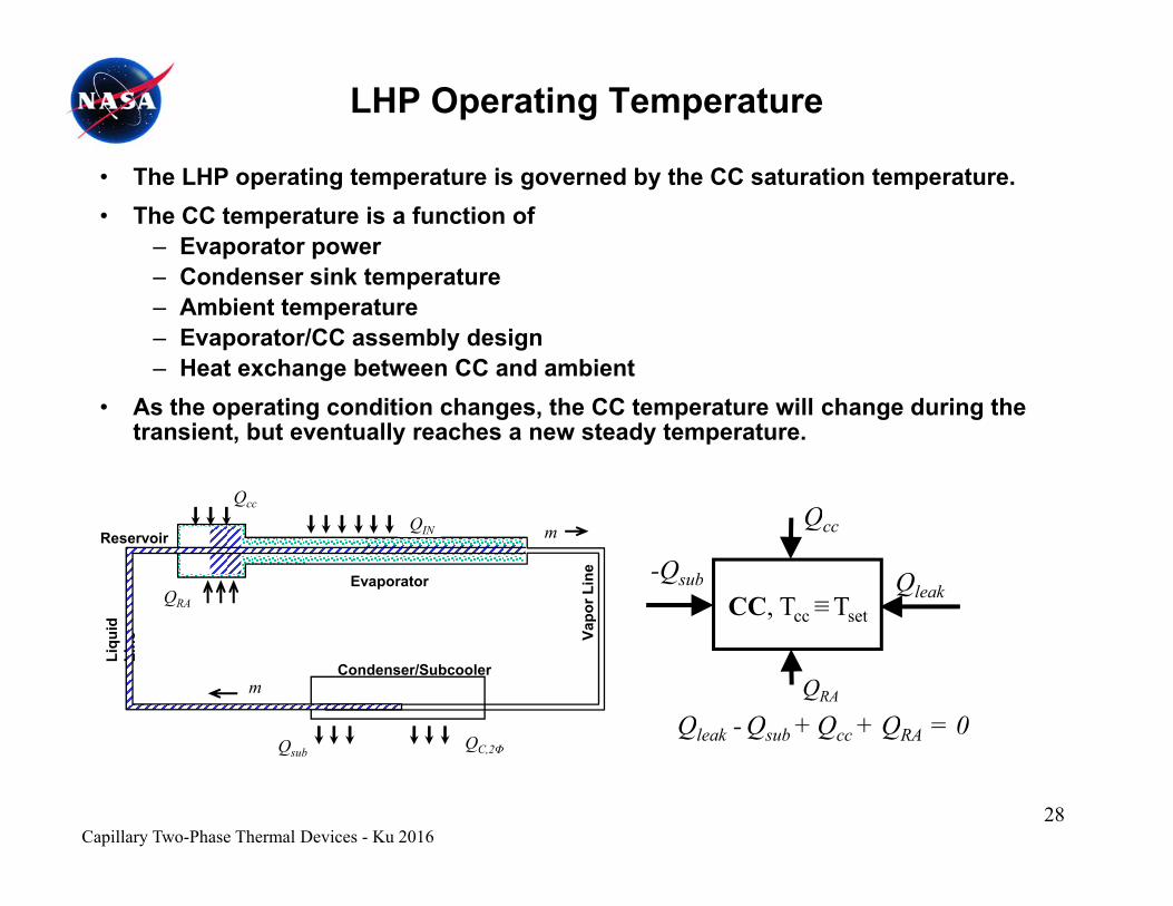
LHP Operating Temperature
CC• The LHP operating temperature is governed by the CC saturation temperature.• The CC temperature is a function of
– Evaporator power– Condenser sink temperatureCondenser sink temperature– Ambient temperature– Evaporator/CC assembly design– Heat exchange between CC and ambient
Qcc
• As the operating condition changes, the CC temperature will change during the transient, but eventually reaches a new steady temperature.
Q
apor
Lin
e
d
Evaporator
ReservoirQIN m
QRA
-Qsub QleakCC, Tcc ≡Tset
Qcc
QRA
Condenser/Subcooler
Va
Liqu
idLi
ne
Q
m
Qleak - Qsub + Qcc + QRA = 0Qsub QC,2Φ
Qleak Qsub Qcc QRA
Capillary Two-Phase Thermal Devices - Ku 201628
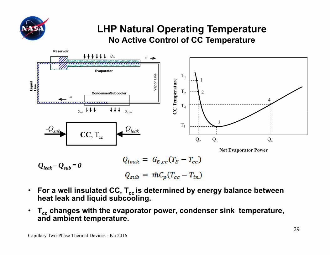
LHP Natural Operating TemperatureNo Active Control of CC Temperature
e
T1 1Line
Evaporator
ReservoirQIN m
CC
Tem
pera
ture
T2
T4
1
24
Condenser/Subcooler
Vapo
r L
Liqu
id
Line
m
-Qsub QleakCC, Tcc
C
T3
Q2 Q3 Q4
3
QC,2ΦQsub
Qleak – Qsub = 0
Net Evaporator Power
• For a well insulated CC, Tcc is determined by energy balance between heat leak and liquid subcooling.T h ith th t d i k t t• Tcc changes with the evaporator power, condenser sink temperature, and ambient temperature.
Capillary Two-Phase Thermal Devices - Ku 201629
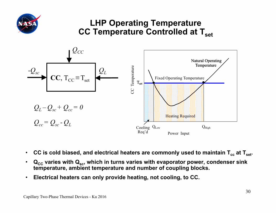
LHP Operating TemperatureCC Temperature Controlled at Tset
QCC
e
Natural Operating Temperature
Natural Operating Temperature
-Qsc QLCC, TCC ≡Tset
CC
Tem
pera
ture
Fixed Operating Temperature
Temperature
Tset
Temperature
Tset
Q Q Q
QL – Qsc + Qcc = 0
C
Heating Required
Qcc = Qsc - QL
Power InputCooling Req’d
QLow QHigh
• CC is cold biased, and electrical heaters are commonly used to maintain Tcc at Tset.• QCC varies with Qsc, which in turns varies with evaporator power, condenser sink
temperature, ambient temperature and number of coupling blocks.• Electrical heaters can only provide heating, not cooling, to CC.
Capillary Two-Phase Thermal Devices - Ku 201630
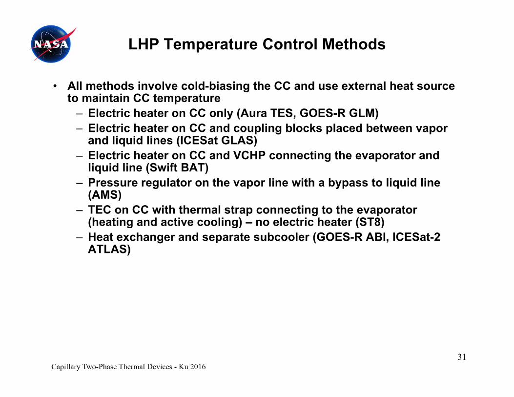
LHP Temperature Control Methods
• All methods involve cold-biasing the CC and use external heat source to maintain CC temperature
– Electric heater on CC only (Aura TES, GOES-R GLM)CC– Electric heater on CC and coupling blocks placed between vapor
and liquid lines (ICESat GLAS)– Electric heater on CC and VCHP connecting the evaporator and
liquid line (Swift BAT)q ( )– Pressure regulator on the vapor line with a bypass to liquid line
(AMS)– TEC on CC with thermal strap connecting to the evaporator
(heating and active cooling) – no electric heater (ST8)(heating and active cooling) no electric heater (ST8)– Heat exchanger and separate subcooler (GOES-R ABI, ICESat-2
ATLAS)
Capillary Two-Phase Thermal Devices - Ku 201631
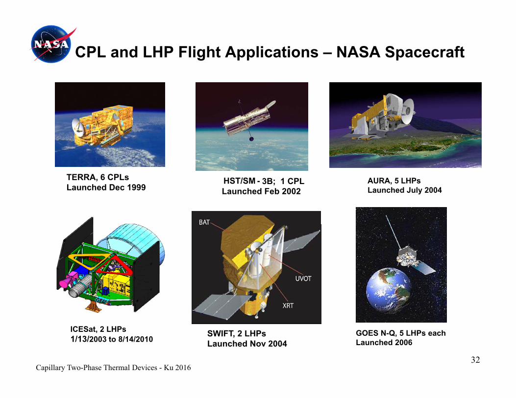
CPL and LHP Flight Applications – NASA Spacecraft
TERRA 6 CP HST/SM - 3B; 1 CPLLaunched Feb 2002
TERRA, 6 CPLsLaunched Dec 1999
AURA, 5 LHPsLaunched July 2004
32
ICESat, 2 LHPs1/13/2003 to 8/14/2010
SWIFT, 2 LHPsLaunched Nov 2004
GOES N-Q, 5 LHPs eachLaunched 2006
Capillary Two-Phase Thermal Devices - Ku 2016

CPL and LHP Flight Applications – NASA Spacecraft
SWOT, 4 LHPsTo be launched
GOES R-U, 4 LHPs eachTo be launched
ICESat-2, 1 LHPTo be launched
• LHPs are also used on many DOD spacecraft and commercial satellitescommercial satellites.
33Capillary Two-Phase Thermal Devices - Ku 2016
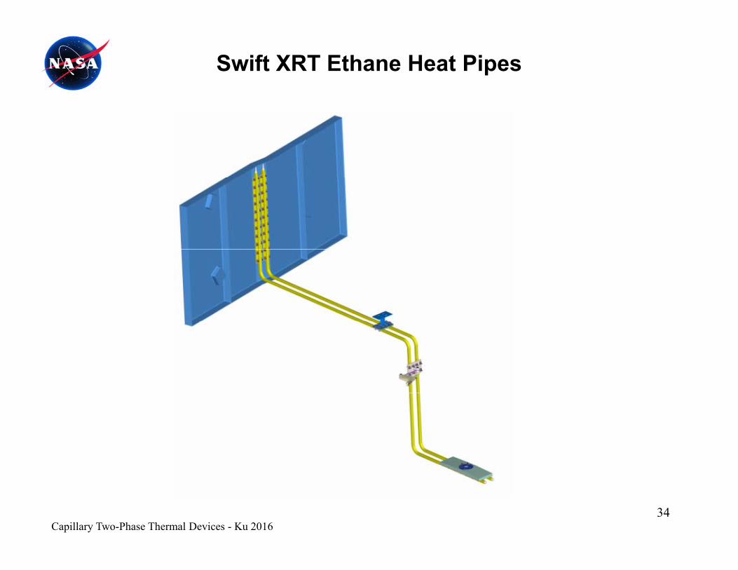
Swift XRT Ethane Heat Pipes
34Capillary Two-Phase Thermal Devices - Ku 2016
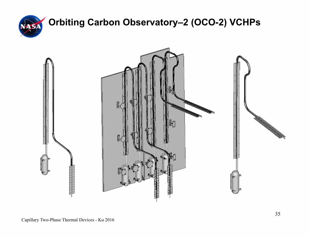
Orbiting Carbon Observatory–2 (OCO-2) VCHPs
35Capillary Two-Phase Thermal Devices - Ku 2016

Terra CPLs - Over 16 years of successful on-orbit operations
• Terra launched 12/1999 • Two-phase loops (CPLs) are on SWIR, TIR and MOPPIT instruments
• On the second day after launch, the first CPL system
y p
On the second day after launch, the first CPL system in a flight mission was started successfully.
• All 3 CPLs continue to demonstrate reliable, stable thermal control for their instruments
• SWIR set temperature reset three times• SWIR set temperature reset three times• Nominal operations continue
36Capillary Two-Phase Thermal Devices - Ku 2016

Terra CPL Flow SchematicVAPOR LINE
FLOW
CONDENSERSTARTER PUMP
ISOTHERMALIZER HEAT PIPE
RADIATOR
RESER
VOIR
TEMPERATURE CONTROLLER
COLD PLATE
LIQUID RETURN LINE
FLOWFLOW
37Capillary Two-Phase Thermal Devices - Ku 2016
J l f 2001 ASTER SWIR l tti t h t
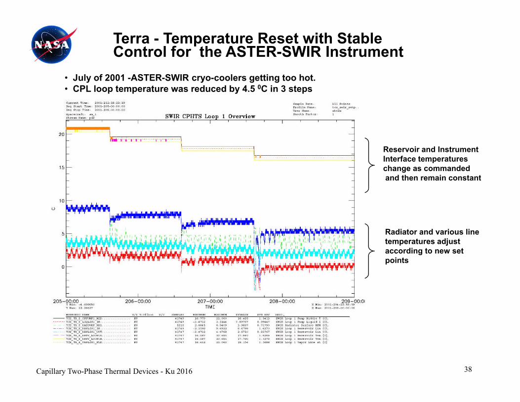
Terra - Temperature Reset with Stable Control for the ASTER-SWIR Instrument
• July of 2001 -ASTER-SWIR cryo-coolers getting too hot. • CPL loop temperature was reduced by 4.5 0C in 3 steps
Reservoir and Instrument Interface temperatureschange as commanded
d th i t tand then remain constant
Radiator and various line temperatures adjust according to new set points
38Capillary Two-Phase Thermal Devices - Ku 2016

CPL on HST/SM-3BSTS-108, Feb/2002
CPL was added to HSTAft Shroud on SM-3B
Astronauts fed CPL t th h b tt
NEONLINES
STIS
evaporator through bottomof shroud, attached it to cryo-cooler, and attached new radiator to handrails.
NICMOSSTIS
CPL removes ~ 400 W heat from NICMOS cryocoolerwhich allows the NICMOSsensor to be reactivated.
Tight temperature control
NICMOSCRYOCOOLER
CPL LINE TO VENTPORTEXTERNAL RADIATOR PORT
CPL EVAPORATOR
39Capillary Two-Phase Thermal Devices - Ku 2016
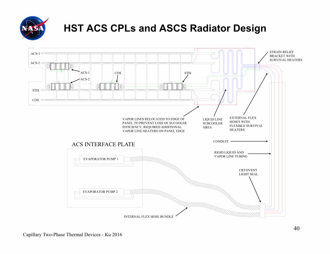
HST ACS CPLs and ASCS Radiator Design
STRAIN RELIEF BRACKET WITH SURVIVAL HEATERS
ACS-1
ACS-2
ACS-1
ACS 2
STISCOS
STIS
COS
ACS-2
ACS INTERFACE PLATE
VAPOR LINES RELOCATED TO EDGE OF PANEL TO PREVENT LOSS OF SUCOOLER EFFICIENCY, REQUIRED ADDITIONAL VAPOR LINE HEATERS ON PANEL EDGE
LIQUID LINE SUBCOOLER AREA
EXTERNAL FLEX HOSES WITH FLEXIBLE SURVIVAL HEATERS
CONDUITACS INTERFACE PLATERIGID LIQUID AND VAPOR LINE TUBING
CRYOVENT LIGHT SEAL
EVAPORATOR PUMP 1
LIGHT SEAL
EVAPORATOR PUMP 2
INTERNAL FLEX HOSE BUNDLE
40Capillary Two-Phase Thermal Devices - Ku 2016
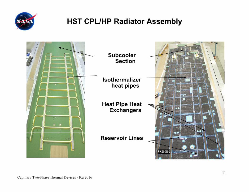
HST CPL/HP Radiator Assembly
Subcooler S tiSection
Isothermalizer h t iheat pipes
Heat Pipe Heat E hExchangers
Reservoir Lines
41Capillary Two-Phase Thermal Devices - Ku 2016
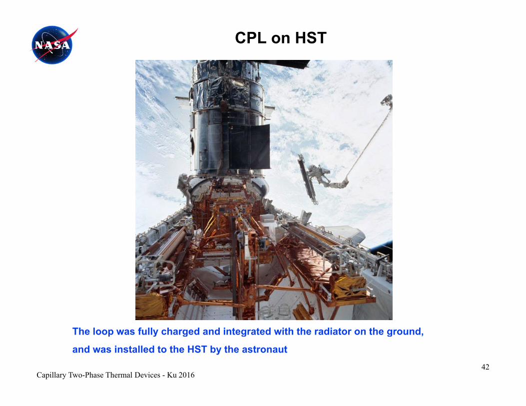
CPL on HST
The loop was fully charged and integrated with the radiator on the groundThe loop was fully charged and integrated with the radiator on the ground,
and was installed to the HST by the astronaut42
Capillary Two-Phase Thermal Devices - Ku 2016
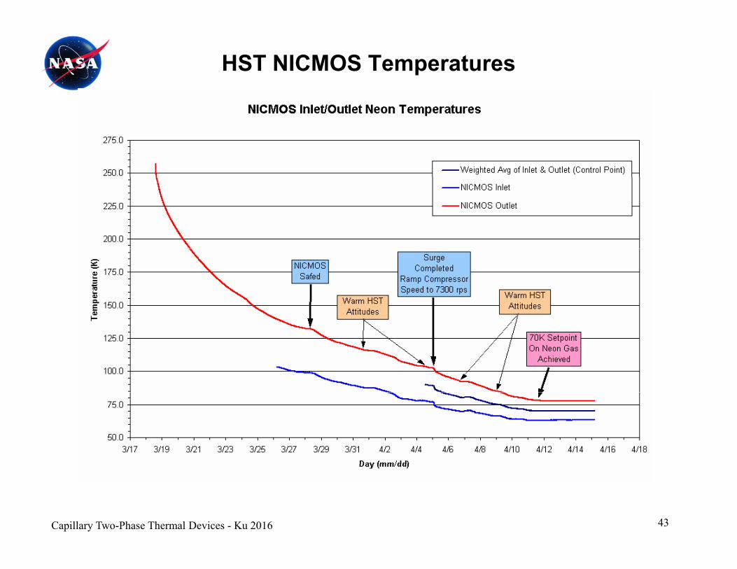
HST NICMOS Temperatures
43Capillary Two-Phase Thermal Devices - Ku 2016
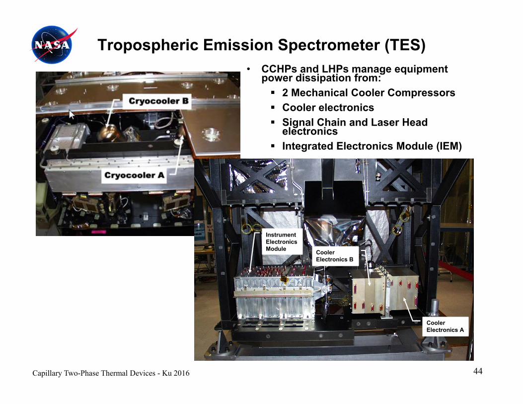
• CCHPs and LHPs manage equipment di i ti f
Tropospheric Emission Spectrometer (TES)
power dissipation from: 2 Mechanical Cooler Compressors Cooler electronics Signal Chain and Laser HeadSignal Chain and Laser Head
electronics Integrated Electronics Module (IEM)
Cooler Electronics B
Instrument Electronics Module
Cooler Electronics AElectronics A
Capillary Two-Phase Thermal Devices - Ku 2016 44
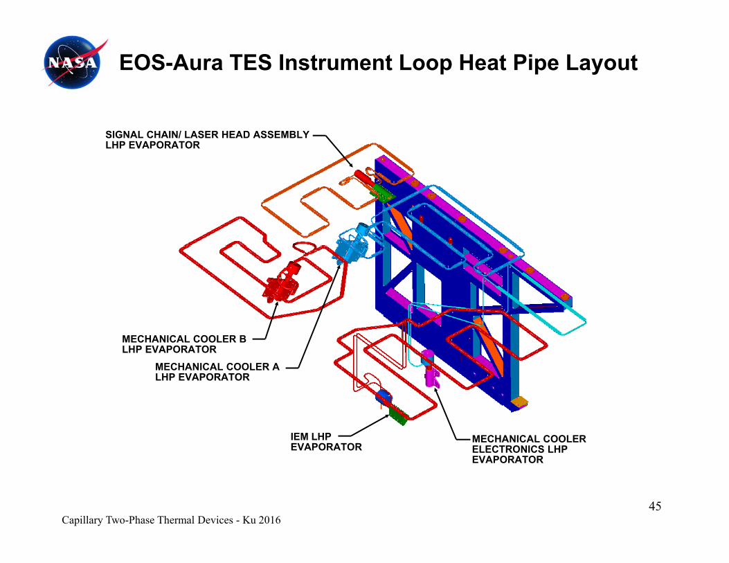
EOS-Aura TES Instrument Loop Heat Pipe Layout
SIGNAL CHAIN/ LASER HEAD ASSEMBLYLHP EVAPORATOR
MECHANICAL COOLER BLHP EVAPORATOR
MECHANICAL COOLER ALHP EVAPORATOR
IEM LHP EVAPORATOR
MECHANICAL COOLER ELECTRONICS LHP EVAPORATOREVAPORATOR
Capillary Two-Phase Thermal Devices - Ku 201645
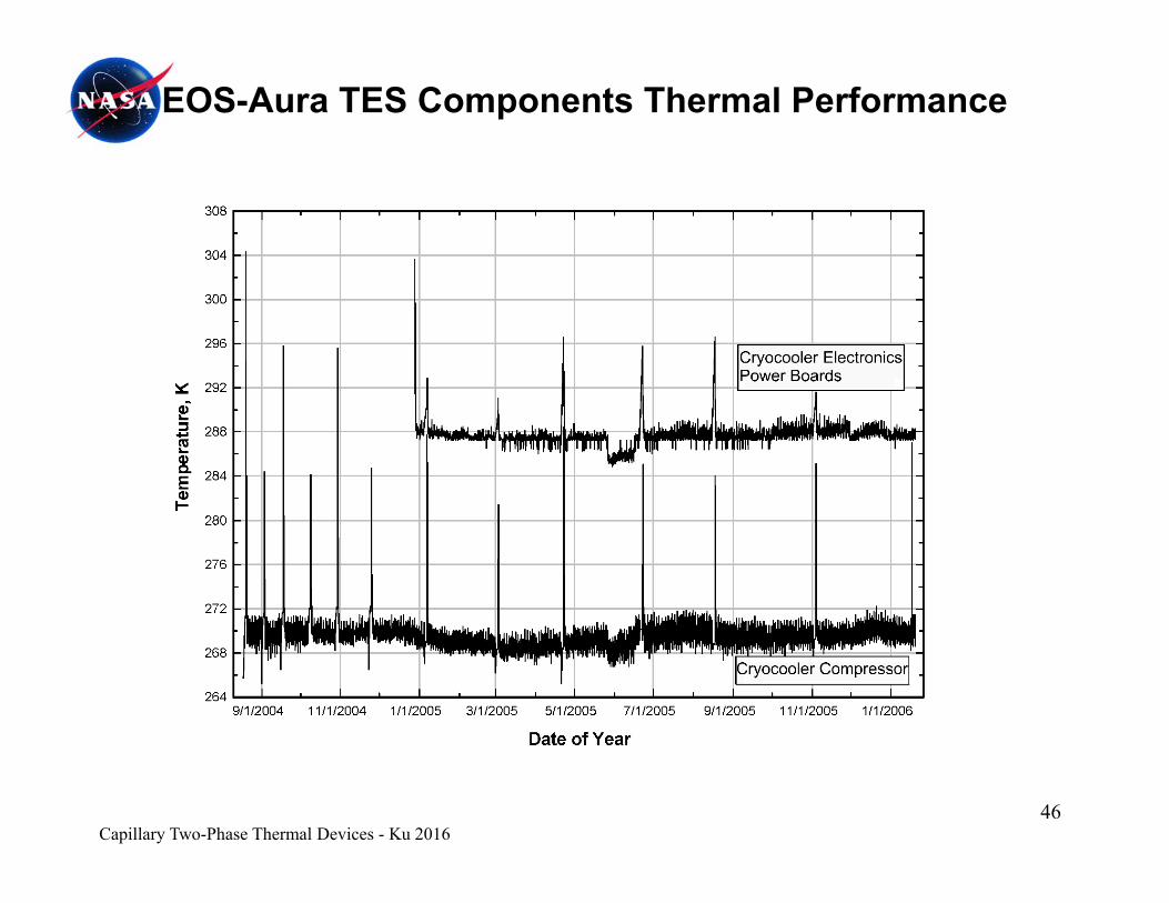
EOS-Aura TES Components Thermal Performance
Capillary Two-Phase Thermal Devices - Ku 201646
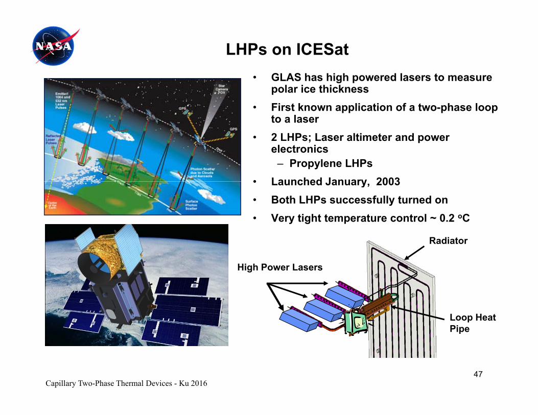
LHPs on ICESat• GLAS has high powered lasers to measure• GLAS has high powered lasers to measure
polar ice thickness• First known application of a two-phase loop
to a laser• 2 LHPs; Laser altimeter and power
electronics – Propylene LHPs
• Launched January 2003• Launched January, 2003• Both LHPs successfully turned on• Very tight temperature control ~ 0.2 oC
High Power Lasers
Radiator
Loop HeatPipe
Capillary Two-Phase Thermal Devices - Ku 201647
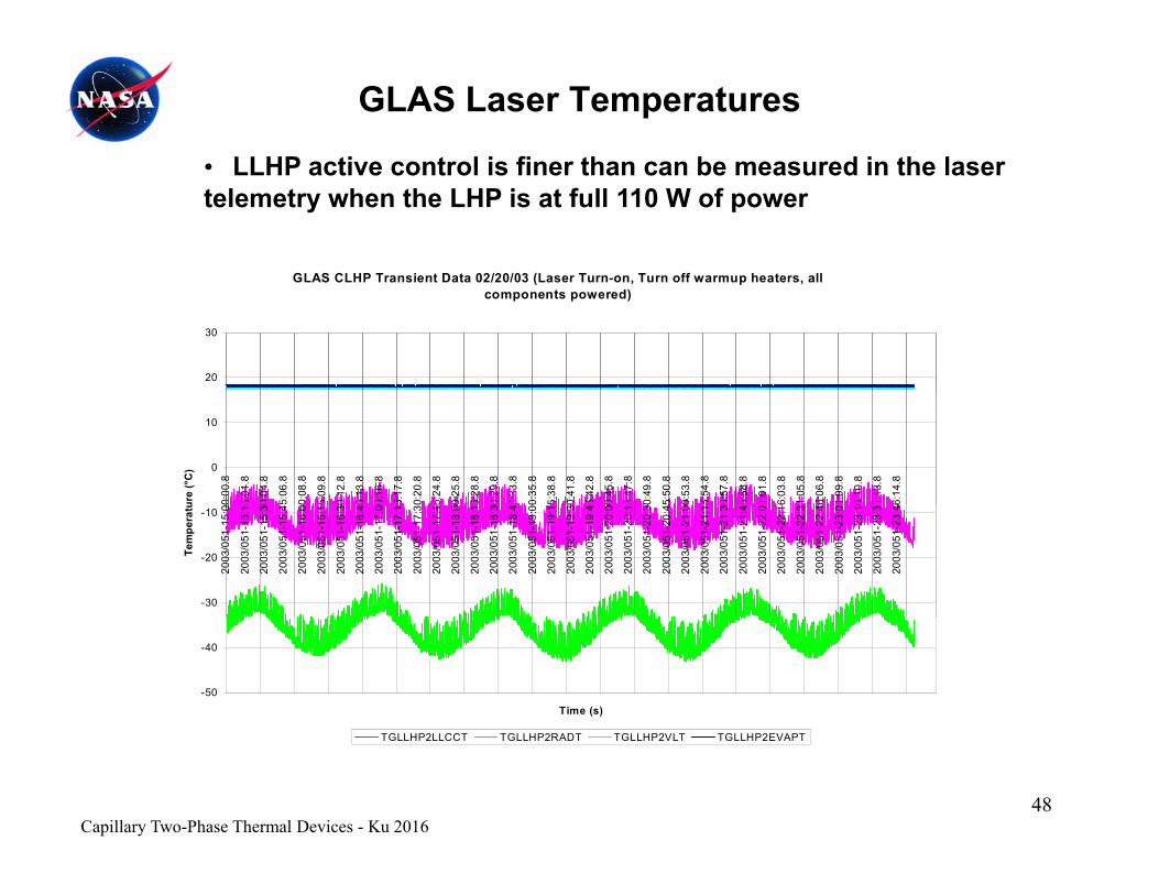
GLAS Laser Temperatures
• LLHP active control is finer than can be measured in the laser
GLAS CLHP Transient Data 02/20/03 (Laser Turn-on Turn off warmup heaters all
• LLHP active control is finer than can be measured in the laser telemetry when the LHP is at full 110 W of power
GLAS CLHP Transient Data 02/20/03 (Laser Turn-on, Turn off warmup heaters, all components powered)
20
30
0
10
0:00
.8
5:01
.8
0:04
.8
5:06
.8
0:08
.8
5:09
.8
0:12
.8
5:13
.8
0:16
.8
5:17
.8
0:20
.8
5:24
.8
0:25
.8
5:28
.8
0:29
.8
5:33
.8
0:35
.8
5:38
.8
0:41
.8
5:42
.8
0:45
.8
5:47
.8
0:49
.8
5:50
.8
0:53
.8
5:54
.8
0:57
.8
5:58
.8
1:01
.8
6:03
.8
1:05
.8
6:06
.8
1:09
.8
6:10
.8
1:13
.8
6:14
.8
ure
(°C
)
-30
-20
-10
2003
/051
-15:
00
2003
/051
-15:
15
2003
/051
-15:
30
2003
/051
-15:
45
2003
/051
-16:
00
2003
/051
-16:
15
2003
/051
-16:
30
2003
/051
-16:
45
2003
/051
-17:
00
2003
/051
-17:
15
2003
/051
-17:
30
2003
/051
-17:
45
2003
/051
-18:
00
2003
/051
-18:
15
2003
/051
-18:
30
2003
/051
-18:
45
2003
/051
-19:
00
2003
/051
-19:
15
2003
/051
-19:
30
2003
/051
-19:
45
2003
/051
-20:
00
2003
/051
-20:
15
2003
/051
-20:
30
2003
/051
-20:
45
2003
/051
-21:
00
2003
/051
-21:
15
2003
/051
-21:
30
2003
/051
-21:
45
2003
/051
-22:
0
2003
/051
-22:
1 6
2003
/051
-22:
3
2003
/051
-22:
4 6
2003
/051
-23:
0
2003
/051
-23:
1 6
2003
/051
-23:
3
2003
/051
-23:
4 6
Tem
pera
tu
-50
-40
Time (s)
TGLLHP2LLCCT TGLLHP2RADT TGLLHP2VLT TGLLHP2EVAPT
Capillary Two-Phase Thermal Devices - Ku 201648
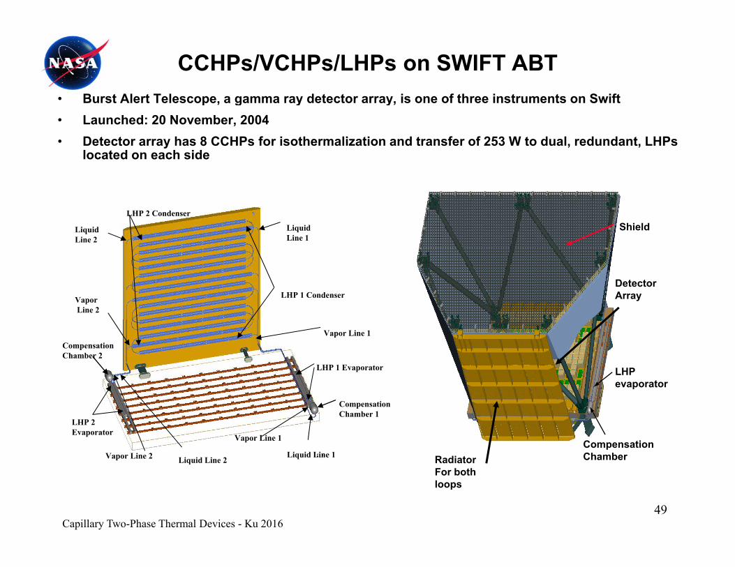
CCHPs/VCHPs/LHPs on SWIFT ABT• Burst Alert Telescope, a gamma ray detector array, is one of three instruments on Swift p , g y y,• Launched: 20 November, 2004 • Detector array has 8 CCHPs for isothermalization and transfer of 253 W to dual, redundant, LHPs
located on each side
ShieldLiquidLine 2
LHP 2 Condenser
LiquidLine 1
DetectorArrayLHP 1 Condenser Vapor
Line 2
LHP evaporator
LHP 1 Evaporator
CompensationChamber 2
Vapor Line 1
CompensationChamberRadiator
CompensationChamber 1
LHP 2 Evaporator
Liquid Line 1 Liquid Line 2Vapor Line 2
Vapor Line 1
RadiatorFor both loops
Liquid Line 2
Capillary Two-Phase Thermal Devices - Ku 201649
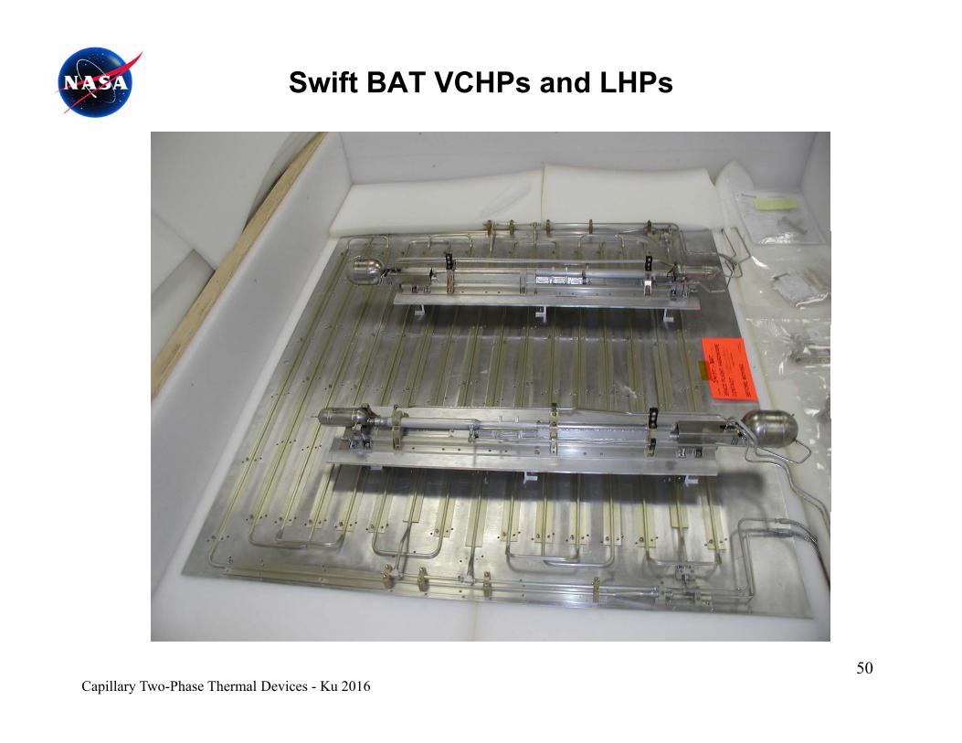
Swift BAT VCHPs and LHPs
Capillary Two-Phase Thermal Devices - Ku 201650
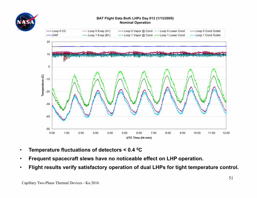
BAT Flight Data Both LHPs Day 013 (1/13/2005)Nominal Operation
Loop 0 CC Loop 0 Evap (A1) Loop 0 Vapor @ Cond Loop 0 Lower Cond Loop 0 Cond OutletDAP Loop 1 Evap (B1) Loop 1 Vapor @ Cond Loop 1 Lower Cond Loop 1 Cond Outlet
10
20
p p ( ) p p @ p p
-10
0
ratu
re (C
)
-30
-20
Tem
per
-50
-40
0:00 1:00 2:00 3:00 4:00 5:00 6:00 7:00 8:00 9:00 10:00 11:00 12:00
• Temperature fluctuations of detectors < 0.4 0C• Frequent spacecraft slews have no noticeable effect on LHP operation.
UTC Time (Hr:min)
• Flight results verify satisfactory operation of dual LHPs for tight temperature control.
Capillary Two-Phase Thermal Devices - Ku 201651
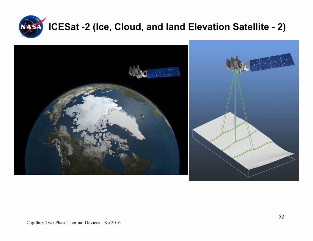
ICESat -2 (Ice, Cloud, and land Elevation Satellite - 2)
52Capillary Two-Phase Thermal Devices - Ku 2016

HPs and LHPs on IceSat-2 ATLAS LTCS
Vapor Line
53Capillary Two-Phase Thermal Devices - Ku 2016
EvaporatorLiquid Line
Reservoir
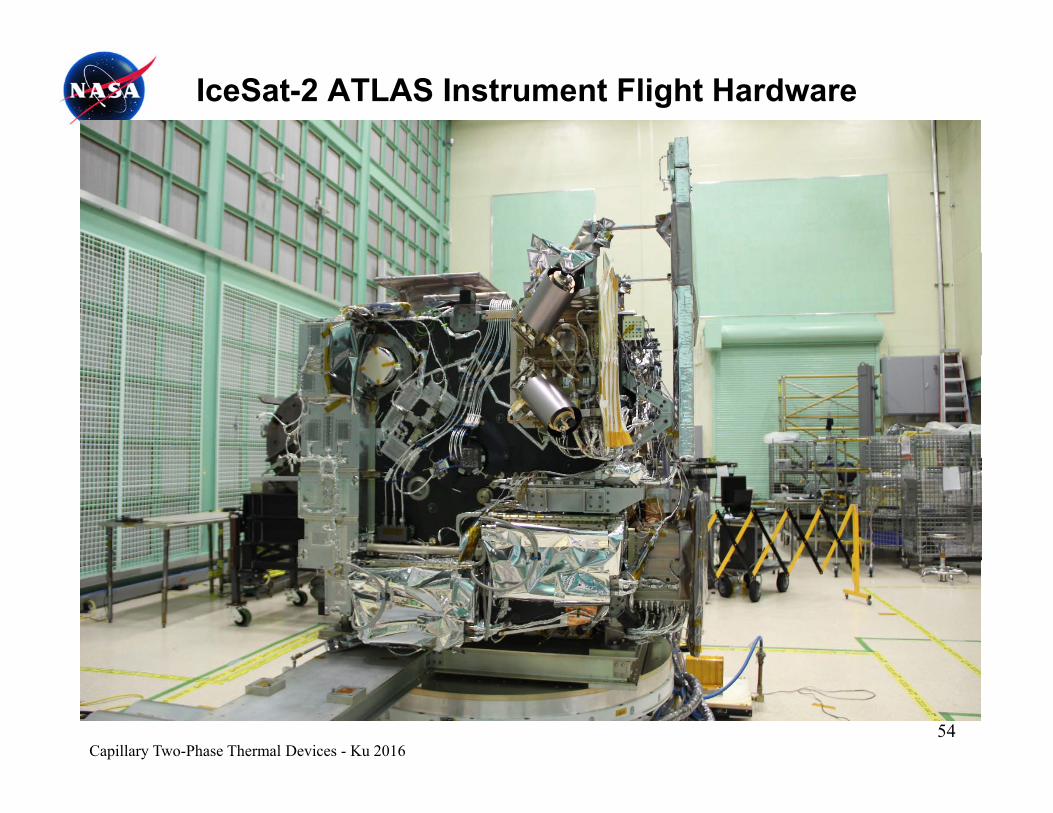
IceSat-2 ATLAS Instrument Flight Hardware
54Capillary Two-Phase Thermal Devices - Ku 2016
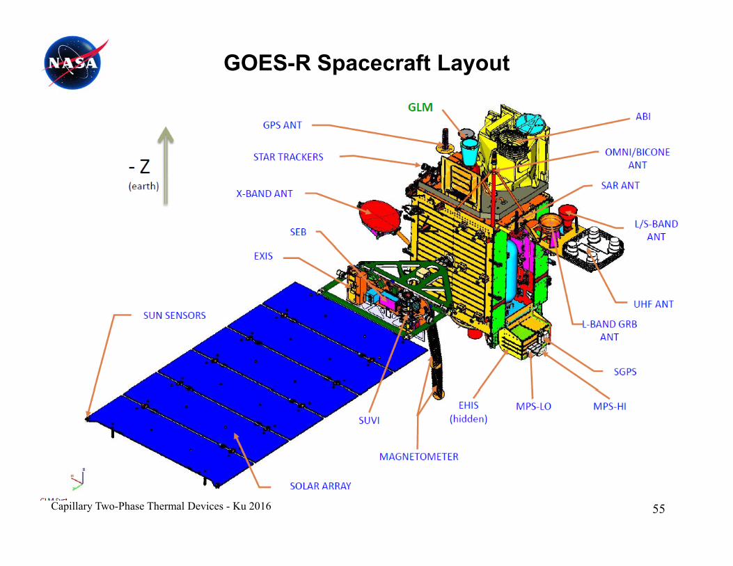
GOES-R Spacecraft Layout
55Capillary Two-Phase Thermal Devices - Ku 2016

GOES-R ABI HPs/LHPs Assembly
+Z Flexures
-Z Flexures
Radiator Panel
Optical BenchAssembly
Heat Pipe
LHP EvaporatorAssemblies
+Z
Heat PipeNetwork
+X +Y
56Capillary Two-Phase Thermal Devices - Ku 2016

GOES-R ABI HPs/LHPs Assembly
57Capillary Two-Phase Thermal Devices - Ku 2016
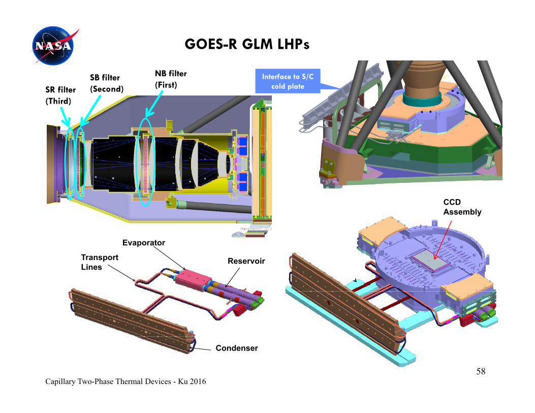
GOES-R GLM LHPs
NB filter SB filter Interface to S/C e(First)
SB filter (Second)SR filter
(Third)
Interface to S/C cold plate
CCD Assembly
Evaporator
ReservoirTransport Lines
Condenser
58Capillary Two-Phase Thermal Devices - Ku 2016
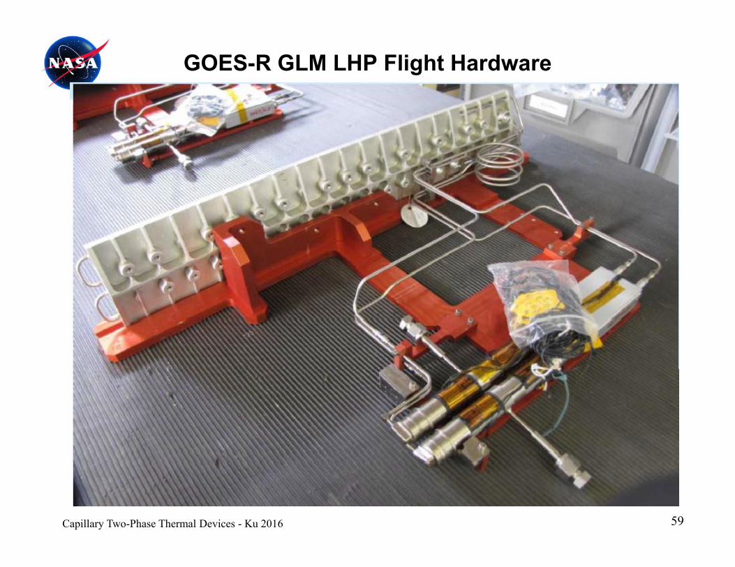
GOES-R GLM LHP Flight Hardware
59Capillary Two-Phase Thermal Devices - Ku 2016

Questions?Questions?