Embed Size (px)
Citation preview

Progress In Electromagnetics Research C, Vol. 16, 69–84, 2010
CANCELLATION OF COMPLICATED DRFM RANGEFALSE TARGETS VIA TEMPORAL PULSE DIVERSITY
G. Lu, S. N. Liao, S. C. Luo, and B. Tang
School of Electronic EngineeringUniversity of Electronic Science and Technology of ChinaNo. 2006, Xiyuan Avenue, West Hi-Tech Zone, Chengdu, China
Abstract—In this paper, a jamming cancelation approach based onthe concept of pulse diversity is proposed to suppress some newercomplicated digital radio frequency memory (DRFM) range falsetargets (RFT). Just repeating the intercepted radar electromagneticsignal, as done in the conventional re-transmitting jammer, is noteffective because only one range false target is produced. In contrast,the newer DRFM-based RFT generation methods, especially choppingand interleaving (C&I) and smeared spectrum (SMSP) can yield amulti-lobe filter output by transforming the internal structure ofthe intercepted radar signal. The presented approach to overcomethis challenge is based on the temporal pulse diversity technique,and it does not require parameter estimation of the jamming signal.By transmitting pulses with specific transmission pulse block andthe following proper processing, it can cancel out the protrudingspikes of the jammer at the price of an acceptable performance loss.Particularly, this method is applicable to broad DRFM repeat jammerin electronic warfare (EW) area.
1. INTRODUCTION
Range false targets (RFT) are employed to jam the victim radar bytransmitting the signals resembling the true target echoes reasonablybut positioned at different ranges. This deception jamming has beenenhanced significantly in recent years with the developments of digitalradio frequency memory (DRFM) techniques [1–3]. Apparently, basedon the DRFM device, the jammer has the ability to generate falsetargets with all the qualities typical of the true targets specified. Hence,
Received 14 June 2010, Accepted 6 September 2010, Scheduled 10 September 2010Corresponding author: G. Lu ([email protected]).

70 Lu et al.
such jamming is liable to be detected as target and makes radar systemscan not search or track properly. Consequently, the real targets can beprotected and the jamming purpose is then achieved.
Furthermore, some newer types of RFTs, which are generatedby transforming and processing the intercepted radar signal moresubtly before transmitting rather than merely re-transmitting, havecome into being. Especially, two effective types of such electronicattack (EA) — C&I and SMSP [4] — were designed to attack theLFM pulse compression radar, which made conditions much moredeteriorated. These two EAs were designed specifically to aim at theradar’s matched-filter, and produced a multi-lobe filter output. Inpractice, it is difficult for the radar to detect and recognize targetwith a multitude of bunched lobe spikes which are positioned aheador behind the true targets and spaced closer than the time duration ofradar signal. Moreover, it is inevitable that more sophisticated RFTswould be excogitated.
For interferences coming from different directions, the spacedomain filtering algorithms can be employed to suppress them [5–7]. But these algorithms may not suitable for DRFM repeat jammer,because radar echo and jammer primarily come from the samedirection. For the conventional DRFM repeat jammer, it is capableof being suppressed by transmitting (quasi-)orthogonal pulses [8, 9],or by applying penalization measures to reduce the power of jammerthrough varying modulated parameters and a three-step matched-filtering approach [10], or by continuously emitting modified versionof previous waveforms following an orthogonal structure in sequenceor simultaneously [11, 12]. The performances of several sorts of CFARprocessor in strong pulse jamming are investigated in [13].
All of the presented EP approaches, however, do not involve thecomplicated jamming types. Consequently, no suppression mechanismsagainst such EA have been addressed in literatures, whereas in ourresearch, the sophisticated RFTs are taken into consideration. Theproposed approach enables the radar to recover echo from jammerby using redundant codes based on temporal pulse diversity concept.Moreover, the approach is capable of dealing with certain potentialjamming even if the transformation is unknown. Apparently, this isa prominent merit different from other methods. The results of theresearch demonstrate that this suppression approach is applicable toa wide range of DRFM repeat jammers. Certainly, these two newjamming — the C&I and SMSP — can be suppressed successfully.
The rest of the paper is organized as follows. Section 2 analyzesthe jammer in details, especially the C&I and SMSP, and gives thedigital representations of the jamming signal. Section 3 describes
Progress In Electromagnetics Research C, Vol. 16, 2010 71
the jamming cancelation algorithm. Section 4 provides simulations.Finally, Section 5 concludes the paper.
2. JAMMING SIGNAL ANALYSIS
The DRFM techniques use a high-speed sampling digital memoryfor storing the intercepted radar signal and later recalling [14, 15].Generally, in a common DRFM-based EA system, the interceptedsignal is first down-converted in frequency, and then sampled andstored in a digital memory. The digital samples are then modulated inphase, amplitude or frequency. Under the control of the system, themodulated signal is later recalled and retransmitted. It follows thatthe signal transmitted back by the DRFM-based jammer is a simplereplica of the original signal with some parameters manipulated.
Different from common DRFM-based jamming, the C&I andSMSP do not simply re-transmit the received signals, but manipulatethe signal complicated before emitting the signals to the victim radar.
The C&I [4] scheme consists of two-step process. First, uniformlyspaced sampling signal segments of the radar pulse are picked out.So, the selected signal segments have certain different time slotsand frequencies. Second, the EA signal is created by placing(concatenating) the segments in the adjacent vacant slots. Thecomponents of the EA signal are segments of the received radarsignal to which the filter transfer function is matched. Consequently,through matched-filtering, the output of this jamming shows a multi-lobe structure. Furthermore, positions of the grouped range lobesare controllable, and this makes it possible to position them aheador behind the true targets.
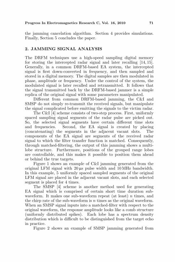
Figure 1 shows an example of C&I jamming generated from theoriginal LFM signal with 20µs pulse width and 10 MHz bandwidth.In this example, 5 uniformly spaced sampled segments of the originalLFM signal are placed in the adjacent vacant slots, and each selectedsegment is placed for 4 times.
The SMSP [4] scheme is another method used for generatingEA signal which is comprised of certain short time duration sub-waveform. It makes one sub-waveform repeat (at least) n times, andthe chirp rate of the sub-waveform is n times as the original waveform.When an SMSP signal inputs into a matched-filter with respect to theoriginal waveform, the response amplitude looks like a comb structure(uniformly distributed spikes). Each lobe has a spectrum densitydistribution which is difficult to be distinguished from the target echoin practice.
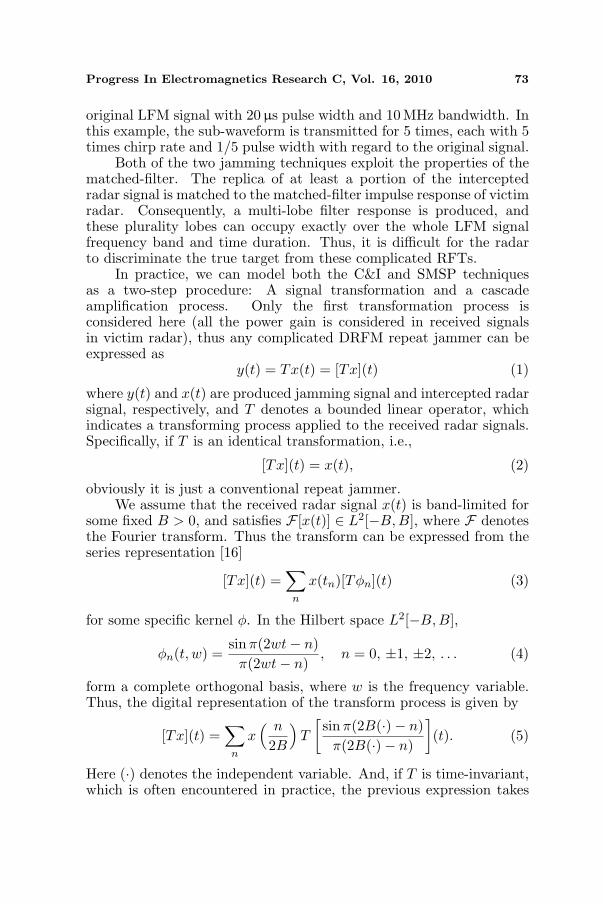
Figure 2 shows an example of SMSP jamming generated from

72 Lu et al.
(a) (b)
(c)
Figure 1. An example of C&I jamming.
(a) (b)
(c)
Figure 2. An example of SMSP jamming.
Progress In Electromagnetics Research C, Vol. 16, 2010 73
original LFM signal with 20µs pulse width and 10 MHz bandwidth. Inthis example, the sub-waveform is transmitted for 5 times, each with 5times chirp rate and 1/5 pulse width with regard to the original signal.
Both of the two jamming techniques exploit the properties of thematched-filter. The replica of at least a portion of the interceptedradar signal is matched to the matched-filter impulse response of victimradar. Consequently, a multi-lobe filter response is produced, andthese plurality lobes can occupy exactly over the whole LFM signalfrequency band and time duration. Thus, it is difficult for the radarto discriminate the true target from these complicated RFTs.
In practice, we can model both the C&I and SMSP techniquesas a two-step procedure: A signal transformation and a cascadeamplification process. Only the first transformation process isconsidered here (all the power gain is considered in received signalsin victim radar), thus any complicated DRFM repeat jammer can beexpressed as
y(t) = Tx(t) = [Tx](t) (1)
where y(t) and x(t) are produced jamming signal and intercepted radarsignal, respectively, and T denotes a bounded linear operator, whichindicates a transforming process applied to the received radar signals.Specifically, if T is an identical transformation, i.e.,
[Tx](t) = x(t), (2)
obviously it is just a conventional repeat jammer.We assume that the received radar signal x(t) is band-limited for
some fixed B > 0, and satisfies F [x(t)] ∈ L2[−B, B], where F denotesthe Fourier transform. Thus the transform can be expressed from theseries representation [16]
[Tx](t) =∑
n
x(tn)[Tφn](t) (3)
for some specific kernel φ. In the Hilbert space L2[−B,B],
φn(t, w) =sinπ(2wt− n)
π(2wt− n), n = 0, ±1, ±2, . . . (4)
form a complete orthogonal basis, where w is the frequency variable.Thus, the digital representation of the transform process is given by
[Tx](t) =∑
n
x( n
2B
)T
[sinπ(2B(·)− n)
π(2B(·)− n)
](t). (5)
Here (·) denotes the independent variable. And, if T is time-invariant,which is often encountered in practice, the previous expression takes
74 Lu et al.
the simpler form
[Tx](t) =∑
n
x( n
2B
)T
[sin 2πB(·)
2πB(·)](
t− n
2B
). (6)
3. PRINCIPLE OF JAMMING CANCELATION
3.1. Scenario
Pulse diversity is an effective way to suppress DRFM repeat jammer.It utilizes the fact that radar varies its transmitting pulses in theslow-time domain, so the jammer is forced to detect and analyze eachupdated pulse. It takes a certain period of time to complete a series ofprocessing before it can transmit a jammer with respect to the updatedpulse. Therefore, we assume the jammer lags one pulse behind theradar. This scenario is reasonable in view of the fact as follows. Evenif the jammer has the ability to receive and re-transmit the currentpulse at once, it can only use the previous pulse coming from the radarwhen it attempts to protect targets which are closer to the radar thanitself. Considering the process time, the actual protection range wouldexpand.
3.2. Radar and Jamming Signal Model
Suppose the radar transmission pulse in slow-time interval u is Pu(t),where t denotes the fast-time. Thus, the jammer transmitting pulsein slow-time interval u can be expressed as T [Pu−1(t)], where T is anoperator defined in Section 2. Consequently, the received pulse of radarin slow-time interval u is as follows
s(t, u) =∑
n
αn(u)pu [t− τn(u)] +∑
l
βl(u)T{pu−1 [t− τl(u)]} (7)
where, αn(u) and βl(u) denote the reflectivity of the target echoes andjamming signals, respectively. And, τn(u) and τl(u) denote the time-delay of the target echoes and jamming signals relative to each pulserepetition interval (PRI), respectively. It is obvious that the receivedradar signals in a given slow-time interval contain both current echoesand re-transmitting jamming with respect to the previous pulse.
In some applications, coding schemes are designed to provide fulldiversity, simple decoding strategy and higher system performance.Here, a real transmission pulse block across four pulse intervals isdefined in Table 1 [17–19], and the corresponding jamming signals areprovided also.

Progress In Electromagnetics Research C, Vol. 16, 2010 75
Table 1. Transmission pulse block I.
u 0 1 2 3
Radar p1(t) p2(t) −p2(t) p1(t)
Jammer T [p0(t)] T [p1(t)] T [p2(t)] T [−p2(t)]
In the initial pulse diversity block, p0(t) may be any arbitrarypulse. Nevertheless, it is definite in subsequent blocks, just the lastradar transmission pulse.
When slow-time u = 1 and 3, according to the transmission pulseblock shown in Table 1, the received signals of radar can be expressedas
s(t, 1) =∑
n
αn(1)p2 [t− τn(1)] +∑
l
βl(1)T{p1 [(t− τ l(1)]} (8)
and
s(t, 3) =∑
n
αn(3)p1 [t− τn(3)] +∑
l
βl(3)T{−p2 [t− τ l(3)]} (9)
The radar transmission pulses in slow-time intervals 0 and 2are also used to disturb the repeat jammer by keeping the jammeranalyzing and processing the updated pulses.
3.3. Jamming Signal Cancelation
When radar works in high pulse repetition frequency (PRF), weassume the echoes reflected from the true targets and the jammingre-transmitted by the jammer are stationary due to the slight changeover several short periods of PRI, and the amplitude of signals maintainconstant in one transmission pulse block. Consequently, for thereceived signal of radar, the reflectivity notations αn(u) and βl(u) canbe reduced to αn and βl, respectively.
For uniform motion target, the round-trip time delay τn(u) andτl(u) can be modeled uniformly as equation below (although thejamming is single-trip actually, it can be simulated by the jammeras round-trip model)
τ(t) =2(R− vt)
c(10)
where R is the initial range of target, v is the relative radial velocitybetween radar and target, and c is the velocity of light. Actually, as wewill see later, even if the assumption of uniform velocity is not fulfilled,it does not affect the performance of cancellation.

76 Lu et al.
The target moves for double PRI from slow-time interval 1 tointerval 3. So, the corresponding time delay difference is
∆τ =4v
cfPRI, (11)
where fPRI denotes PRF. Because a high-repetition frequency isassumed, and v is much smaller than the light velocity c, the magnitudeof ∆τ is generally very small in the level of nanosecond. For instance,when v = 1 km/s and fPRI = 10 kHz, we have ∆τ = 1.33 ns. Inthis example, the PRF is not extremely high. If the PRF increasesmuch higher, which is frequently encountered in practice, the time-delay difference will be much smaller.
Because the pulse signal is processed in base band, the signalsampling rate (uniform sampling is assumed) is then relatively in alower level, generally varying within several to tens of million samplesper second (MSPS) after decimating, namely the sampling interval isgreater than ten nanoseconds at least.
Accordingly, the time span with respect to the adjacent samplingpoints is greater than the time-delay difference by roughly an order ofmagnitude at least. So, the slight difference across two pulse intervalsderived from target moving is no more than one sampling point inmost practice cases. It is confirmed that the error introduced by thetime delay difference is likely less than the error introduced in thesampling process. Hence, this error can be negligible completely onsuch conditions. We may notice that uniform velocity is not a necessarycondition to deduce this conclusion. As a result, whether the uniformvelocity is assumed or not, the conclusion is valid only if the error isless than one sampling point.
In some exceptional cases, the time-delay difference of eachinteresting arrival pulse can not be simply neglected. Under thiscondition, it can be compensated by easily multiplying the frequencyresponse of the matched-filter by a delay factor or aligning the leadingedge of received pulses over specific intervals if the time-delay differencecan be estimated or obtained from other sensors, or errors will beintroduced.
Accordingly, the time-delay τn(u) and τl(u) can be simplyexpressed as τn and τl, respectively. Where, τn and τl denote thetime-delay after compensating or simply neglecting the difference.Although the Doppler shift of the target (both the true and the false)is not apparently addressed in above text, the effect aroused by itcan be completely negligible in view of the high PRF and the actualacceleration of target. Thus the received signals in slow-time interval

Progress In Electromagnetics Research C, Vol. 16, 2010 77
1 and 3 are given by
s(t, 1) =∑
n
αnp 2(t− τn) +∑
l
βlT [p1(t− τ l)] (12)
ands(t, 3) =
∑n
αnp1(t− τn)−∑
l
βlT [p2(t− τ l)]. (13)
To achieve the purpose of jamming cancellation, the receivedsignals in slow-time interval 1 and 3 pass through matched-filterseparately with respect to the true targets and then add together,namely
sn(t) = p∗2(−t)⊗ s(t, 1) + p∗1(−t)⊗ s(t, 3)
= p∗2(−t)⊗{∑
n
αnp2(t− τn) +∑
l
βlT [p1(t− τl)]
}
+p∗1(−t)⊗{∑
n
αnp1(t− τn)−∑
l
βlT [p2(t− τl)]
}
=∑
n
αnpsfp2(t− τn) + p∗2(−t)⊗
∑
l
βlT [p1(t− τl)]
+∑
n
αnpsfp1(t− τn)− p∗1(−t)⊗
∑
l
βlT [p2(t− τl)] (14)
where pu ∗ (−t) denotes the impulse response of matched-filter focusedon the true targets in slow-time interval u, the asterisk denotesconjugate, ⊗ denotes the convolution operation, and psf(t) denotespoint spread function (psf). It is clear that the terms 1st and 3rdwhich contain psf(·) on the right side of (14) embody information oftarget, while the terms 2nd and 4th relate to the jammer. Since thedigital representation of operator T is known, we can substitute (5)or (6) into the expression p∗2(−t) ⊗ ∑
l
βlT [p1(t− τl)] and p∗1(−t) ⊗∑l
βlT [p2(t− τl)], respectively. Generally, p∗2(−t) ⊗ T [p1(t − τl)] 6=p∗1(−t) ⊗ T [p2(t − τl)], i.e., the jammer-related terms can not becanceled. But, in a special case where p1(t) = p2(t), the cancelationcan be performed. Therefore, if p1(t) is selected identical with p2(t),(14) becomes
sn(t) =∑
n
αn[psfp1(t− τn)+psfp2
(t− τn)] (15)
Evidently, the jammer terms have been canceled. On the otherhand, if we focus only on the suppression of false target, a feasibletransmission pulse block without full diversity can be given in Table 2.

78 Lu et al.
Based on this pulse block, the cancelation result is given as follows.
sn(t) = p∗2(−t)⊗ s(t, 1) + p∗2(−t)⊗ s(t, 3)
= p∗2(−t)⊗{∑
n
αnp2(t− τn) +∑
l
βlT{p1[−(t− τl)]}}
+p∗2(−t)⊗{∑
n
αnp2(t− τn)−∑
l
βlT{p1[−(t− τl)]}}
= 2∑
n
αnpsfp2(t− τn) (16)
As expected, the RFTs are canceled completely. Accordingto (14), (15) and (16), the jammer-related terms can be canceledcompletely when required conditions are satisfied. No other specialconstrains have been imposed upon the derivation. In theory, thecancelation performance of the proposed method is independent of theJSR and jamming clearance.
4. SIMULATIONS
In simulations, the LFM signal with bandwidth 10MHz and pulsewidth 20µs is employed. Besides, the sampling frequency is 40 MSPS,namely the time interval is 25 ns. A target echo is received in thepresence of a C&I or SMSP jammer with jamming-to-signal ratio (JSR)equal to 15 dB. In the process of pulse compression, the matched-filtering measure is applied with a rectangle window.
4.1. Using Pulse Block I
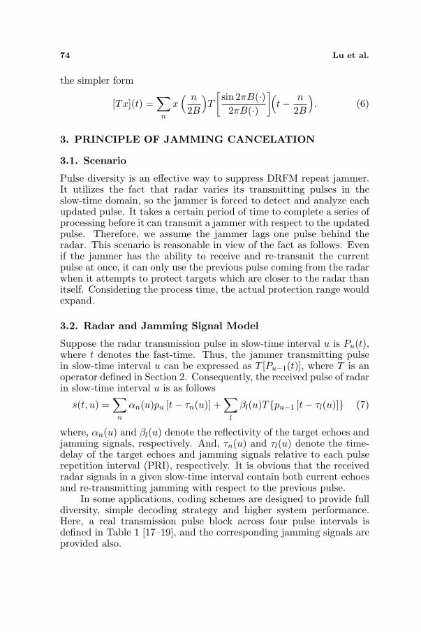
Here, we choose the transmission pulse block I defined in Table 1.As described in Section 3.3, however, the pulse p1(t) and p2(t) mustbe identical here. The proposed approach is employed to cancel thejamming, and the direct matched-filtering method is used also in orderto show different effect.
First, C&I jamming is tested. It can be seen clearly fromFig. 3(a) that the signal processed by direct matched-filtering still
Table 2. Transmission pulse block II.
u 0 1 2 3
Radar p1(−t) p2(t) −p1(−t) p2(t)
Jammer T [p0(t)] T [p1(−t)] T [p2(t)] T [−p1(−t)]
Progress In Electromagnetics Research C, Vol. 16, 2010 79
(a)
(b)
Figure 3. Cancelation of C&I jamming using transmission pulse blockI.
(a)
(b)
Figure 4. Cancelation of SMSP jamming using transmission pulseblock I.

80 Lu et al.
(a)
(b)
Figure 5. Cancelation of C&I jamming using transmission pulse blockII.
remains a cluster of false targets. While, as shown in Fig. 3(b), theproposed approach can cancel out the jammer and focus the true targetdistinctly.
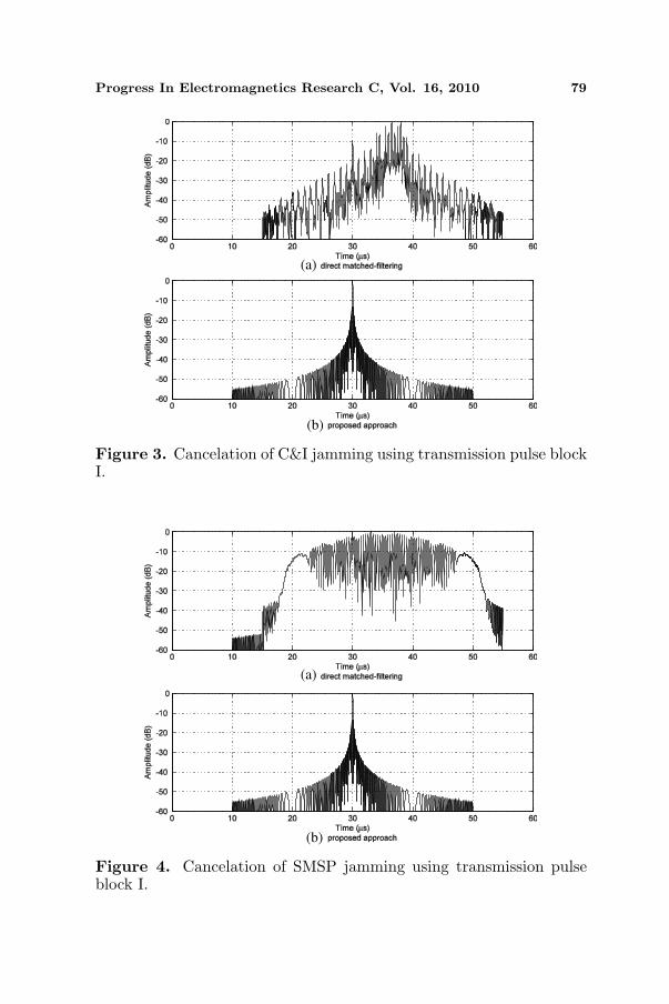
Second, SMSP jamming is applied to jam the victim radar. InFig. 4(a), there are comb outputs besides the true target. Conversely,as shown in Fig. 4(b), the complicated false targets have beensuppressed and the true target is obtained.
4.2. Using Pulse Block II
In this simulation, the transmission pulse block II defined in Table 2is used. Unlike the previous case, the pulse width parameter is set to20µs and 15µs while other conditions are remained. It follows that wealter simply the pulse width of the signal in transmission block, i.e.,p1(t) 6= p2(t).
In Figs. 5 and 6, the cancelation effects of C&I and SMSP areshown respectively to evaluate the algorithm based on a transmissionblock without full diversity. It is proved that the jamming signal canbe eliminated successfully and the cancelation performance is almostidentical with using transmission block I.

Progress In Electromagnetics Research C, Vol. 16, 2010 81
(a)
(b)
Figure 6. Cancelation of SMSP jamming using transmission pulseblock II.
(a) (b)
(c) (d)
Figure 7. RMS of recovered target signal by using block I/II.
82 Lu et al.
4.3. RMS of Recovered Target Signal
Here, the ratio of mainlobe to sidelobe (RMS) of recovered target signalis provided also to evaluate the performance of the presented approach.In this simulation, the signal-to-noise ratio (SNR) varies from −10 to15 dB and the JSR varies from 5 to 15 dB. The noises are additive,Gaussian and white. Monte Carlo simulation is run 250 times.
As shown in Fig. 7, the RMS ranges from 10.8 to 14.5 dBand gradually converges to 13.4 dB (rectangle window) as the SNRincreases. In addition, this simulation shows that the JSR isindependent of the RMS.
5. CONCLUSIONS
This paper addresses issues about the newer types of complicatedDRFM repeat jamming and presented a method to suppress them.By exploiting the redundant but essential code pulses, the proposedapproach enables radar to recover the true target signals easilythrough jamming cancelation. Different from other methods, it isefficient to suppress complicated jamming signals besides conventionalones. The research results of the present work demonstrate that theproposed approach is applicable to a wide-ranging scope of DRFMrepeat jammer, particularly the C&I and SMSP, even some potentialcomplicated ones. It provides radar with an active strategy to counteragainst the repeat jammer, not just a passive anti-jamming method.
REFERENCES
1. West, P. D. and B. J. Slocumb, “ECM modeling for assessment oftarget tracking algorithms,” IEEE Proc. 29th Southeastern Symp.System Theory, 500–504, Cookeville, USA, Mar. 1997.
2. DiFilippo, D., G. Geling, and G. Currie, “Simulator for advancedfighter radar EPM development,” IEE Proceedings Radar Sonarand Navigation, Vol. 148, No. 3, 139–146, 2001.
3. Pace, P. E., D. J. Fouts, S. Ekestorm, and C. Karow, “Digital false-target image synthesiser for countering ISAR,” IEE ProceedingsRadar Sonar and Navigation, Vol. 149, No. 5, 248–257, 2002.
4. Sparrow, M. J. and J. Cikalo, “ECM techniques to counter pulsecompression radar,” United States Patent 7081846, Jul. 2006.
5. Mouhamadou, M., P. Armand, P. Vaudon, and M. Rammal, “In-terference suppression of the linear antenna arrays controlled byphase with use of SQP algorithm,” Progress In ElectromagneticsResearch, Vol. 59, 251–265, 2006.
Progress In Electromagnetics Research C, Vol. 16, 2010 83
6. Mahmoud, K. R., M. El-Adawy, S. M. M. Ibrahem, R. Bansal,K. R. Mahmoud Visiting, and S. H. Zainud-Deen, “Performanceof circular Yagi-Uda arrays foe beamforming applicationsusing particle swarm optimization algorithm,” Journal ofElectromagnetic Waves and Applications, Vol. 22, No. 2–3, 353–364, 2008.
7. Guney, K. and S. Basbug, “Interference suppression of linearantenna arrays by amplitude-only control using a bacterialforaging algorithm,” Progress In Electromagnetics Research,Vol. 79, 475–497, 2008.
8. Garmatyuk, D. S. and R. M. Narayanan, “ECCM capabilitiesof an ultrawideband bandlimited random noise imaging radar,”IEEE Transaction on Aerospace and Electronic Systems, Vol. 38,No. 4, 1243–1255, 2002.
9. Schuerger, J. and D. Garmatyuk, “Deception jamming modelingin radar sensor networks,” IEEE Military CommunicationConference, 1–7, San Diego, USA, Nov. 2008.
10. Soumekh, M., “SAR-ECCM using phase-perturbed LFM chirpsignals and DRFM repeat jammer penalization,” IEEE Transac-tion on Aerospace and Electronic Systems, Vol. 42, No. 1, 191–205,2006.
11. Akhtar, J., “An ECCM scheme for orthogonal independent range-focusing of real and false targets,” IEEE Radar Conference, 846–849, Boston, USA, Apr. 2007.
12. Akhtar, J., “An ECCM signaling approach for deep fading ofjamming reflectors,” IET International Conference on RadarSystems, 1–5, Edinburgh, UK, Oct. 2007.
13. Garvanov, I. and C. Kabakchiev, “One and two dimensions CFARprocessors in the presence of strong pulse jamming,” Cyberneticsand Information Technologies, No. 1, 58–72, 2002.
14. Roome, S. J., “Digital radio frequency memory,” ElectronicCommunication Engineering Journal, Vol. 2, No. 4, 147–153, 1990.
15. Greco, M., F. Gini, and A. Farina, “Radar detection andclassification of jamming signals belonging to a cone class,” IEEETransaction on Signal Processing, Vol. 56, No. 5, 1984–1993, 2008.
16. Habib, M. K., “Digital representations of operators on band-limited random signals,” IEEE Transaction on InformationTheory, Vol. 47, No. 1, 173–177, 2001.
17. Lu, H.-F., P. V. Kumar, and C. Habong, “On orthogonaldesigns and space-time codes,” Proceedings of IEEE InternationalSymposium Information Theory, 418, Lausanne, Switzerland,

84 Lu et al.
2002.18. Alamouti, S. M., “A simple transmit diversity technique for
wireless communications,” IEEE Journal Selected Areas inCommunications, Vol. 16, No. 8, 1451–1458, 1998.
19. Su, W. F. and X.-G. Xia, “Quasi-orthogonal space-time blockcodes with full diversity,” IEEE Global TelecommunicationsConference, 1098–1102, Taipei, China, Nov. 2002.