Embed Size (px)
Citation preview
1V1TJ1
Several EAA members have written ask-ing about how to design canards or threesurface airplanes. This month I'd like to tellyou how they work and what you need toknow in order to design an unconventionalairplane.
WHY A CANARD?
I've never designed a canard airplane, butI've worked on several of them. Examples oftrue canards are the VariEze, Long-EZ, Star-ship, Quickie and ARES. You would evaluatea canard configuration when you have thefollowing design requirements:
• safe behavior at high angles of attack isthe main design goal
• you want the smallest possible packageusing a pusher engine
• you have no convenient place to mounta conventional horizontal tail
You are already familiar with the conceptof stability, having spent so much time onthat point while developing the tail spread-sheets. In an aft-tail configuration, you makethe plane more stable by making the tail big-ger. The horizontal tail, after all, is well be-hind the center of gravity. At high angles ofattack, then, its lift will pull up on the tail androtate the airplane to a lower angle of attack.We want to avoid large angles of attack, be-cause the airplane can lose its control effec-tiveness or can depart into a spin. Thescenario usually reads: stall . . . spin . . .crash . . . burn . . . die.
As you've seen from looking at the tail CLrequired to trim the airplane in the tailspreadsheet, the horizontal tail never has towork very hard, relative to its maximum liftingcapacity. The biggest problem for the hori-zontal tail is trying to live in the downwashof the wing, which keeps changing the angleof attack of the tail. There is a lot of residual
by JOHN G. RONCZ, EAA 11281115450 Hunting Ridge Tr.Granger, IN 46530-9093
lifting power in the horizontal tail which isnormally not needed to trim the airplane. Inother words, the tail CL needed to trim theairplane is nowhere near the tail's maximumCL. Having all this extra lifting power left overin the tail means that it's pretty easy for thetail to force the main wing to stall, and to holdthe airplane above the wing's stalling angleof attack. What happens next depends uponthe stalling behavior of the wing, andwhether or not the controls remain effective.The easiest way out of this mess is to pushforward on the stick, in order to use all thattail power to lower the nose and get the heckout of this stalled condition as soon as pos-sible. This is possible because the lift of thetail is far from the center of gravity, and alittle lift force from the tail multiplied by a biglever arm will make a huge pitching moment.Making the tail bigger increases stability be-cause any lift from a flying surface which islocated behind the center of gravity will tendto reduce the airplane's angle of attack.
CANARD STABILITY
Moving the tail to the front of the airplanechanges this picture. Any lifting surface lo-cated ahead of the center of gravity de-stabilizes the airplane, because its lift willtend to increase the airplane's angle of at-tack. Therefore, if you mount a wing aheadof the center of gravity, you must make it assmall as possible in order to minimize its de-stabilizing effect.
In a canard arrangement, one wing isahead of the center of gravity, while anotherwing is behind the center of gravity. Thecanard airplane is supported, then, like a
beam sitting on two sawhorses. The conven-tional airplane is more like a beam sitting onone sawhorse, with a weight sitting on oneend of the beam to make it balance, muchlike the see-saw I've been using as an exam-ple. It should come as no surprise, then, thata canard can have a better ride throughbumpy air than a conventional airplane.
If we look at the goal of having a nice nose-down pitching moment at the stall, how dowe do this with a canard? The obvious an-swer is that we pull the front sawhorse outfrom under the beam! If the canard, which isin front of the c of g, stalls while the wingbehind the c of g is still flying, then the nosewill lower itself automatically. At a lowerangle of attack the canard will unstall, andits restored lift will again increase the angleof attack until it stalls again. This gives thefamiliar "pitch-buck" behavior which is famil-iar to anyone who has flown a canard. Thedisadvantage of this is that when the canardstalls the airplane will pitch down uncom-manded. If this happens just above the run-way, the airplane will hit nosewheel first nomatter how hard the pilot is pulling back onthe stick.
When we were studying stability, welearned that the center of gravity has to beahead of the neutral point. We located thispoint of neutral pitch stability by looking athow all the pitching moments acting on ourairplane change when the angle of attack ischanged. When you do this for a canardairplane, you find that to make it stable thecenter of gravity has to be located pretty farforward. After you know where the center ofgravity is, it's easy to determine how muchweight is resting on each of the two wingedsawhorses. The results will show that thecanard has to lift about twice the weight persquare foot of the main wing! This tail isn'tloafing, like that on a conventional airplane
SPORT AVIATION 57
- it is working very hard for its living. This isa direct consequence of making the de-stabilizing surface as small as possible. Ifyou try to reduce the canard's CL by givingit more area, all you do is destabilize theairplane more, and the neutral point will sim-ply move forward. To keep the airplanestable, you have to move the center of grav-ity further forward as well, which puts moreweight on the front sawhorse again. Youcan't fool Mother Nature!
What would happen if the wing stalled butthe canard didn't? In that case, the canardwould raise the nose while the wing let thetail drop. There would be a sudden increasein the airplane's angle of attack. This is notgood! It is not true, however, that you cannever let the back wing stall on a canard.Even on a stalled airplane, there are forcesat work (lift, drag and gravity) - and each ofthese forces has a lever arm back to thecenter of gravity. It's OK to have both thecanard and the wing stalled, as long as thepitching moments trying to lower the noseare greater than those trying to raise thenose.
CONTROLLING THE STALL
In general, though, you want to design theairplane so that the canard stalls before thewing. To do this you must control when thecanard and wing reach their respective stal-ling angles of attack. Those of us who'vewatched the Concorde land at Oshkosh cer-tainly noticed that its angle of attack was ex-tremely high . . . so high that the nose hasto be physically tilted down to let the pilotsee anything over the nose! Why? Becauseit has a low aspect ratio wing. Aspect ratiois defined as wingspan squared divided bythe wing ara. You'll recall that aspect ratio isthe largest factor in determining how muchlift you get for each degree angle of attack(the others were speed and sweep). Re-member that wingtips are leaky, and that as-pect ratio really tells you the ratio of "non-leaking" wing perimeter to "leaking" wingperimeter. The lower the aspect ratio, then,the more "leaky" the wing is, and the greaterthe angle of attack will have to be in orderto produce a certain amount of lift. The Con-corde's wing not only has a low aspect ratio,but also leaks more due to its high sweepangle.
One way to ensure that the canard stallsbefore the wing is to give it a higher aspectratio than the wing. This means that thecanard will make more CL for each degreeangle of attack than the wing, and will there-fore reach its maximum CL and stall beforethe wing does.
If you study the charts in Theory of WingSections, you'll see that a wing with a de-flected flap stalls at a lower angle of attackthan an unflapped wing. So another way ofmaking the canard stall first is to put a flapon it. You can call this flap an elevator, anduse it for pitch control. To get to high anglesof attack, you will raise the nose by deflectingthis elevator trailing edge down, increasingthe canard's lift. Having the elevator de-flected means that you will have lowered thecanard's stalling angle of attack.
If you study successful canards, such asthose by Burt Rutan, you'll see that he usedboth these techniques in his designs.58 JANUARY 1991
77.170420.590
105.206
101.75
72.841
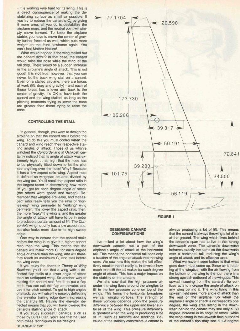
FIGURE 1
DESIGNING CANARDCONFIGURATIONS
I've talked a lot about how the wing'sdownwash cancels out a pan of theairplane's angle of attack at the horizontaltail. This means the horizontal tail sees onlya fraction of the angle of attack that the wingsees. We saw how this makes the tail effec-tively smaller than it really is, in terms of howmuch extra lift the tail makes for each degreeangle of attack. This has a major impact onthe stability of the airplane.
We also saw that the high pressure airunder the wing flows around the wingtips tofill in the low pressure zone on top of thewings. This forms the horizontal tornadoeswe call wingtip vortices. The strength ofthese vortices depends upon the pressuredifference between the upper and lower sur-faces of the wing. This pressure differenceis greatest when the wing is producing a lotof lift, such as takeoffs and landings. Be-cause of the stability constraints, a canard is
always producing a lot of lift. This meansthat the canard is always throwing a lot of airat the ground. The wing which lives behindthe canard's span has to live in this strongdownwash zone. The canard's downwashbehaves exactly the same as the downwashover a horizontal tail, reducing the wing'sangle of attack and its effective area.
What we haven't seen before is that whatgoes down must come up. Since air is rotat-ing at the wingtips, with the air flowing fromthe bottom of the wing to the top, there is astrong upwash outboard of the wingtips. Thisupwash coming from the canard's tip vor-tices acts to increase the angle of attack onany wing behind it. The wing living in thisupwash field sees more angle of attack thanthe rest of the airplane. So when theairplane's angle of attack is increased by onedegree, the wing area sitting in the down-wash behind the canard may see only a .60degree increase in its angle of attack, whilethe wing sitting in the upwash field outboardof the canard's tips may see a 1.3 degree
increase in its angle of attack.The effect of this downwash/upwash com-
bination is to make it difficult to calculate twoimportant parameters: first, the neutral pointfor the airplane, and second, the variation inCL along the back wing. We'll talk about theneutral point first.
The neutral point is determined by cal-culating how much each force acting on theairplane will change when the airplane'sangle of attack changes. Let's take the backwing of a Long-EZ, and divide it spanwiseinto 10 strips, starting at the fuselage andending at the wingtips. Each of the stripscontains a certain number of square feet ofwing area. We don't care how many poundsof lift each strip is producing. We need toknow how many pounds of additional lifteach strip would produce if the airplane'sangle of attack is increased by one degree.You can't figure this out unless you know theamount of downwash or upwash which thatstrip sees after the airplane is rotated to itshigher angle of attack. Since the canard iscreating all this downwash and upwash, itsshape and location relative to the wing willstrongly influence the wing's angle of attackat each spanwise strip.
This means that if the canard is at 16 de-grees angle of attack, part of the wing behindit will be at 9 degrees angle of attack (be-cause it's in the canard's downwash), whileanother strip of the wing may be at 19 de-grees angle of attack (because it's in thecanard's upwash).
There is just no simple way to calculatethis in a spreadsheet. The simplest tool thatcan do this is called a vortex-lattice computerprogram. It divides the airplane up into littletrapezoidal grids (the alttice), and computesthe amount of lift coming from horseshoevortices glued to each of the trapezoids, andhow this lift affects each of the other littletrapezoids. In our tail spreadsheet, we as-sumed that the angle of downwash is uni-
form over the horizontal tail. If we used avortex-lattice program, we could have di-vided the tail into 50 little panels, and wewould have seen that the downwash angleis different for each spanwise location on thetail. This kind of detailed knowledge is whatit takes to understand the complex flow be-hind a canard.
The other important parameter is to knowwhat the lift coefficient is at each spanwisestrip on the wing. We need to know this tomake sure that we are not stalling some partof the main wing which is living in the upwashfrom the canard. So in the computer you putthe airplane at the angle of attack at whichthe canard is stalling (CLmax), then you lookat all the spanwise strips along the wing andcheck to be sure that you haven't exceededthe wing's CLmax anywhere. If you have, youneed to twist the wing, to lower its angle ofattack in the critical region, or move thecanard, or perform other surgery on the con-figuration.
THE AIRFOIL PROBLEM
If you designed the beast correctly, thecanard stalls first, and prevents the airplanefrom increasing its angle of attack further.Therefore, the maximum lift that you can getfrom the whole airplane depends entirelyupon the maximum lift coefficient (CLmax)that the canard airfoil can achieve before itstalls. The stability constraint has forced ahigh aspect ratio upon you. This in turnmeans long skinny canards. The killer struc-tural engineers have forced you to select avery thick airfoil, because the strength of thespar depends upon its depth. Meanwhile, thechord length is small relative to the span,keeping the Reynolds numbers low. LowReynolds numbers make the airfoil prone toearly flow separation, reducing CLmax. All ofthis makes the design of airfoils suitable foruse on canards very challenging, and there-
fore a lot of fun! The ideal airfoil should pro-duce gobs of lift, have no drag, be as thickas it is wide, and be totally unaffected byrain, hail, ice or bugs. Good luck!
The ideal back wing airfoil, meanwhile,would have fully attached flow right up untilit begins to stall. After it stalls, it should main-tain its stalling lift coefficient well beyond thestalling angle of attack. You need to havefully attached flow in order to get as muchlift as possible for every degree more angleof attack - for stability reasons. You want tomaintain the maximum lift well past the stallalso for stability reasons, since you want tokeep as much lift as possible acting behindthe center of gravity to generate the nose-down pitching moment you need.
THE FLAP PROBLEM
The greatest disadvantage to canardairplanes is that it is difficult to put flaps onthe main wing. Remember that the canarditself is already flapped (the elevator), and isalready working as hard as it can. If you putflaps on the main wing, the wing would gen-erate even more lift, which would raise thetail and lower the nose. After you pull full aftstick to raise the nose, you'll find that theairplane is still diving. The reason is that thecanard can't produce enough lift to balancethe airplane when flaps are deflected on therear wing. This is not good!
The solution that Burt Rutan invented forthe Starship (and for which he holds the pa-tent) involves using variable sweep on thecanard. This is very clever, and I'd like youto appreciate how clever it really is. Bear withme while I explain how it works. The problemBurt faced was simple: how do you balancethe airplane with flaps on the rear wing? Put-ting the flaps down adds lift to the back wing.This extra lift is produced behind the centerof gravity, and would cause the airplane topitch nose down. The canard already has a
123456789101 11 21314151617181920212223242526272829
AFORMULAS FROM A
FOOT CHORDROOT BUTTLINEROOTLE<3>FS-1/4 CHORD @ FS
TIP CHORDTIP BUTTLINETIP LE <§> FS-1/4 CHORD <S>FS
WING SPANTAPER RATIO1/4 CHORD OF MACBUTTLINE OF MACPANEL AREA:
PANEL *123
WING AREA:AVERAGE CHORD:BL OF MAC AT1/4 CHORD @ FSLE MAC @ FS
B I CPRIL1990 SPORT AVIATION
50.1 91! INCHES39.200 INCHES101.75 INCHES
=B5+0.25*B3 INCHES
20.590 INCHES173.730 INCHES
77.17 INCHES-B1 0+0.25*68; INCHES
-2*173.73/12 FEET= B8/B3
-B6+(816-B4)/(B9-B4)*(B11-B6} INCHES-B4+1/3*(B9-B4)*(1+2*B14)/(1+B14) INCHES
-(B3 + B8)*{B9-B4)/144 SQUARE FEET
IPANEL AREA 'BLOFMAC
19.0960 12.25010.8525 31.71366.1262 97.088
-sum(B21..B23) SQUARE FEET-B25/B1 3*1 2 INCHES
-Sum(E21..E23)/B25 INCHES-Sum(F21..F23)/B25 INCHES
= B28-0.25'B26 INCHES
D
1/4 CHORD115.780115.053100.537
E
BL MOMENT=B21'C21=B22'C22=B23*C23
F
1/4C MOMENT=B21*D21-B22*D22-B23*D?3
FIGURE 2SPORT AVIATION 59
full-span slotted flap (elevator) which is work-ing as hard as it can. How can you get morelift from it?
The solution goes back to the fundamentalphysics of computing the lift-curve slope.The lift curve slope measures how much liftyou get for each degree angle of attack.We've already seen on the Concorde thatthe biggest driver is the aspect ratio. Thenext is sweep. If you sweep a wing, youlower the amount of lift it gets for each de-gree angle of attack. In a variable-sweepwing, two things happen. First, the lift curveslope is reduced as the wing is swept. Sec-ond, the center of lift of the wing is movedaft as well.
Burt used both these effects. When theflaps on the main wing are deployed fortakeoff or landing, the canard is unswept (ac-tually, it's swept very slightly forward). Thismoves its center of lift further forward, givingthe canard more of a lever arm to the centerof gravity. The longer lever arm permits thecanard to generate more nose-up pitchingmoments to counter the nose-down pitchingmoments that the flaps create. More impor-tantly, when the canard is unswept, it willproduce more lift for any given airplane angleof attack, because its lift curve slope will behither. If you go back and compare lift curveslopes (dCL/dALPHA) for zero and thirty de-grees of sweep in the April spreadsheet,you'll see that you get around 14% more liftper degree angle of attack at zero sweepthan at 30 degrees of sweep.
By combining the two effects, the Starshipis able to use flaps on the back wing and stillhave the canard balance the airplane. Thedisadvantage is that the flaps can't be de-flected as much as a normal airplane. TheStarship has Fowler flaps that move back alot on tracks, giving the wing more area, butthey are deflected only about 14 degrees.The reason you can't deflect them more isthat with high amounts of deflection, the flowbegins to separate from the top of the flap.While the lift continues to go up with higherangles of attack, you gain a smaller amountof lift for each degree angle of attack thanyou would if the flow had not separated.
To help you picture this, we can make upsome numbers. Say the airplane goes fromsix to seven degrees angle of attack withoutchanging its speed or altitude (the airplaneis in a wind tunnel). This is a one degreechange. The wing lift goes up by 1000pounds. Then we go from seven to eight de-grees. We gain another 1000 pounds of lift.Then we go from eight to nine, at which pointthe flow begins to separate from the flap. Wetherefore gain 900 pounds of lift, which isless than we expected to get. From nine toten we get 800 pounds more lift, becausethe separated zone on the top of the flap isgetting bigger. You can see that as the flowseparation increases, you get less lift foreach degree more angle of attack.
The reason this is important is becausepitch stability depends on how much the liftchanges with angle of attack. If flow separa-tion happens on the back wing, due to a largeflap deflection, you won't gain as much liftas you should. The effect is to move the neu-tral point forward, making the airplane moreunstable in pitch. (If you got 900 pounds oflift instead of the 1000 pounds you expected,it has the same effect on stability as if youshrank the wing by 10% of its area.) That'swhy, if you put flaps on the back wing of a60 JANUARY 1991
canard, it's important to avoid flap deflectionangles which could cause flow separation onthe flaps.
Pulling full aft stick also causes thecanard's flap (elevator) to be fully deflected.This will cause some flow separation on thecanard. The reason this is not a problem isthat flow separation on a wing which isahead of the center of gravity effectivelymakes that wing smaller. This increases thestability of the airplane.
The bottom line is that a canard has tohave a bigger wing than a conventionalairplane, in order to land at the same speed.Even with flaps, the flaps can't be pushed totheir maximum potential due to the fear offlow separation. The canard configurationhas one little wing in front and a big wing inback. The little wing is pushed to itsmaximum performance, while the big wingloafs. To minimize wing area, and thereforeweight and wetted area, it makes moresense to make the big wing work as hard asit can and let the little wing loaf.
THREE SURFACE AIRPLANES
I have designed a three-surface airplane,and have worked on a few others. Examplesof three-surface airplanes are the Grizzly,Avanti, Triumph, Catbird, and AT"3 (Ad-vanced Technology Tactical Transport). Allthose wings represent job security for anaerodynamicist! I keep hoping that someonewill come up with a four-surface airplane!
The three-surface airplane allows high-liftflaps to be used on both canard and mainwing. Having another tail in the back in-creases the stability of the airplane, and al-lows use of a bigger canard surface. Puttingthe elevator on the rear tail frees the canardfrom having to do this job as well.
The main advantage to having a three-sur-face airplane is that you can position themain wing further aft. In a conventional ar-rangement, the center of lift of the wing hasto be very near the center of gravity of theairplane. The inevitable result is that you endup with a big spar crossing the cabin justwhere you don't want it. Putting another lift-ing surface up front allows you to move thewing further back. On the Avanti it ends upcompletely behind the cabin where it doesn'tbother anyone. Burt Rutan put a vestigialcanard on the Catbird so that he could movethe main wing spar back also. On my home-built I used forward sweep to accomplish thesame goal.
Remember that an airplane is first andforemost a packaging problem. On the AT" 3,the amount of fuel the airplane needs for itsmission will not fit inside the wing. Ratherthan use a tip tank for external fuel tankage,the extra fuel is contained in two pods whichtie the front and middle wings together. Thismakes a stiffer structure (therefore lighter),and serves as a convenient place to parkengines and main gear as well. Grizzly alsouses the same idea, except that it is a single.
I chose the three-surface configuration forthe Eagle-X aircraft I designed in Australia,for other reasons. I feel that a 3-surfaceairplane can produce higher maximum liftthan any other configuration. The AT"3, forinstance, achieved a CLmiu of 3.2 in flighttests! In order to meet the 40 knot Australianstall speed, I put flaps on the front and middle
wings. The configuration also allows the pilotand passenger to sit behind the front wingand ahead of the back wing, which meansthey have unobstructed vision both downand up. It also results in smaller wings withlower damping in roll. This was important be-cause at low speeds it is hard to get enoughaileron power. The Eagle-X demonstrated a39 knot stall speed with relatively high wingloading, with very powerful roll control at alltimes. I also like the three-surface configura-tion because it offers a large range of optionsto "tune" the handling qualities of theairplane. As I like to say, it has many buttonsyou can push to get what you want. TheEagle-X also violates the rule I gave you ear-lier, in that the canard has a lower aspectratio than the wing. The reason is that bothwings are interchangeable except for theirspans, in order to reduce the productioncosts. For the same reason both flaps areinterchangeable, including their spans. Inspite of this aerodynamic handicap, theairplane had the best flying qualities of anyairplane I have every flown.
DESIGNING ATHREE-SURFACE AIRPLANE
If you thought the upwash/downwash situ-ation was difficult for a canard, wait 'til yousee a three-surface airplane! The downwashfrom the canard changes the angle of attackat the wing behind it. The wing in turn addsdownwash to that and sends it back over thetail. You also have the usual canard upwashsituation to deal with. So determining theneutral point and spanwise distribution of liftis even more difficult. There is no way tomodel such a thing using only a spread-sheet.
In the movie Amadeus, which I liked a lot,the emperor told Mozart that his music had"too many notes." A three-surface airplaneis a lot like that when you try to figure outhow to trim it. You can trim the airplane usingonly canard lift, in which case the tail doesn'thave to lift anything at all. Or you can makethe canard lift do most of the trimming, thencarry negative lift on the tail for the rest. Youcan divide up the trim loads between canardand tail equally, with the canard lifting upand the tail lifting down. You can also trimby having all three surfaces lifting. You caneven set the canard up for zero lift and trimusing only the tail. Too many notes!
The way I finally settled this issue was toset the wing and tail incidences to producethe right distribution of lift for minimum in-duced drag for some condition. For a twinthis condition is a one-engine climb. For asingle it is at the speed for its best lift-to-drag(glide) ratio. There is no hard and fast rulefor doing this, since each configuration hasits own optimum. So take it on faith that thereis a way to divide the lift up among all thesewings such that you end up with theminimum induced drag.
DISADVANTAGES OF HAVINGTHREE SURFACES
Earlier we talked about how a conven-tional tail has a lot of power left over evenafter the main wing has stalled. A three-sur-face airplane is even worse, because it hasa wing ahead of the center of gravity. The
123456789101 11213141S161718
~2~6~212223242526272829
A B C D E FrORMULAS FROM APRIL1 990 SPORT AVIATION i [
ROOTCHORO _ROOT BUTTUNEROOTL£@FS =1/4 CHORD @FS j
TIP CHORDTIP BUTTUNETIPLE@FS-1/4 CHORD @FS _,
WING SPANTAPER RATIO1/4 CHORD OF MACBUTTLINE OF MACPANEL AREA: j
i50.1 91] INCHES"39.200; INCHES101.75 INCHES11 4. 30 INCHES 1
i ;20.590 INCHES i i
173.730 INCHES i i77.17 INCHES j T82.32 INCHES I I
28.96 FEET i !0.410: j i
100.537 INCHES 197.088 INCHES |
66. 1262 SQUARE FEET............................. — j... . . . . . . ........... __.... _...............
pANELi •-•--- •--•1 ~123
WING AREA:AVERAGE CHORD:BL OF MAC AT1/4 CHORD @FSLEMAC@FS
: : i
PANEL AREA'BL OF MAC 1/4 CHORD "BL19.0960 12.250 115.78010.8525] 31.713i 115.053166.1262 97.088 100.537!
i j96.075 SQUARE FEET !39.81 7 INCHES i f72.841 INCHES
105.206 INCHES !95.252 INCHES ! i
'
........ .........._.4.——— .--.-.......
. . . . . ........................................... .
MOMENT 1/4C MOMENT233.93 2210.93344.17 1248.61
6420.06' 6648.13
FIGURE 3
canard will happily lift the nose to higher an-gles of attack, on top of which you have allthat rear tail power available to also raise thenose. Getting to really high angles of attackis therefore very easy for a three-surfaceairplane. Getting rid of as much canard liftas possible at the stall is a step in the rightdirection. On the Catbird and Triumph, I de-signed canards which have brutal stallcharacteristics, in that they stall all at oncevery abruptly. Still, the pilot can overcomethe resulting nose-down pitching momentjust by using the remaining power in the reartail.
The Piaggio Avanti sprouted delta wingsshaped in an inverted V at the aft end of thefuselage for this reason. Delta wings haveboth low aspected ratio and are highly swept.These combine to make the lift-curve slopequite low, meaning that the little delta wingsneed enormous angles of attack in order toreach their maximum lift. So even when allthree of the other wings have stalled, thelittle deltas hang in there, cranking out liftnear the tail. This lift pulls the tail up. rotatingthe whole airplane nose-down, which is whatyou want. You can see the same trick usedon modern Learjets.
The other disadvantages are increasedcomplexity and higher interference drag. In-stead of one flap motor you have two, whichmust be rigged in such a way that it's impos-sible to put the canard flaps down unless thewing flaps also move. Otherwise you couldend up with pitching moments which are im-possible to overcome. You also have morewing attach structures because of havingmore wings to attach! Finally, every time youhave a place on an airplane where one partmates to another, the intersection createsdrag. Three-surface airplanes have more in-tersections, and need greater attention to de-tail in order to avoid a drag penalty.
All of these problems are solvable, how-ever. I do expect to see the three-surfaceconfiguration become more popular in thefuture, because it does offer a lot of flexibility
in laying out the airplane. It also makes a lotof lift for its wing areas.
QUESTIONS FROMHOMEBUILDERS
I got a couple of good questions at myOshkosh forums, and would like to answerthem now. The first person is designing anairplane which uses a double-tapered wing.He wanted to know how to calculate itsaerodynamic center. The spreadsheet as-sumes that the wing is a straight taper fromroot to tip. This is a very good question.
My own homebuilt can be considered asa three-taper wing. Figure 1 shows how Ifigured its wing areas. The usual way is toextend the trailing edges to the centerline ofthe fuselage. I never do this on a taperedwing, because I think it puts too much imag-inary area inside the fuselage. While it's truethat the lift carries from the wing up and overthe top of the fuselage, making the fuselageproduce lift much like the wing buried insideit would have, I think the best the fuselagecan do is to mimic the wing chord right at theintersection. My homebuilt also keeps theleading edge straight out to Buttline 39.2,which gives a break in the top view as well.
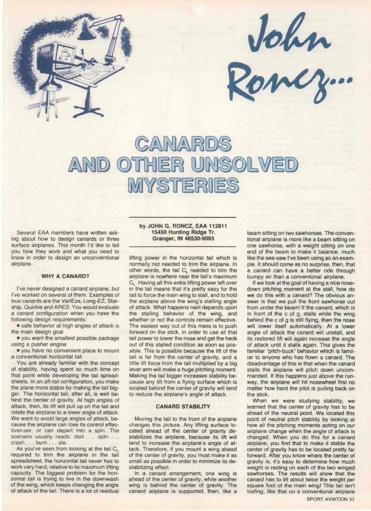
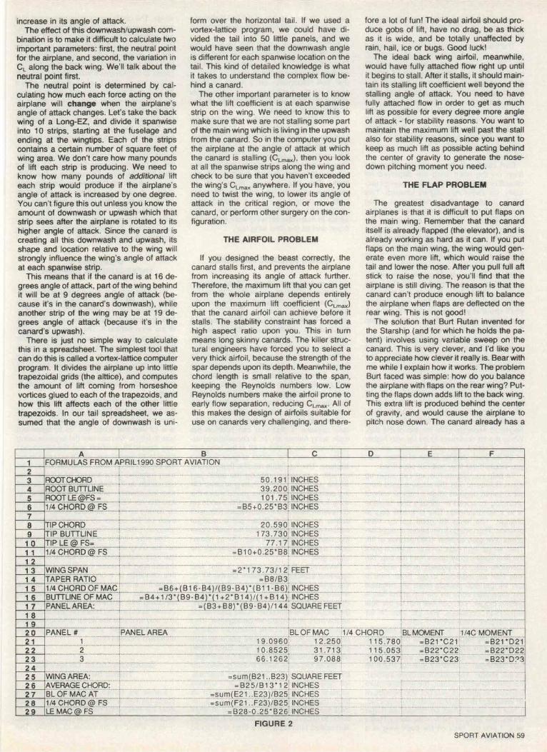
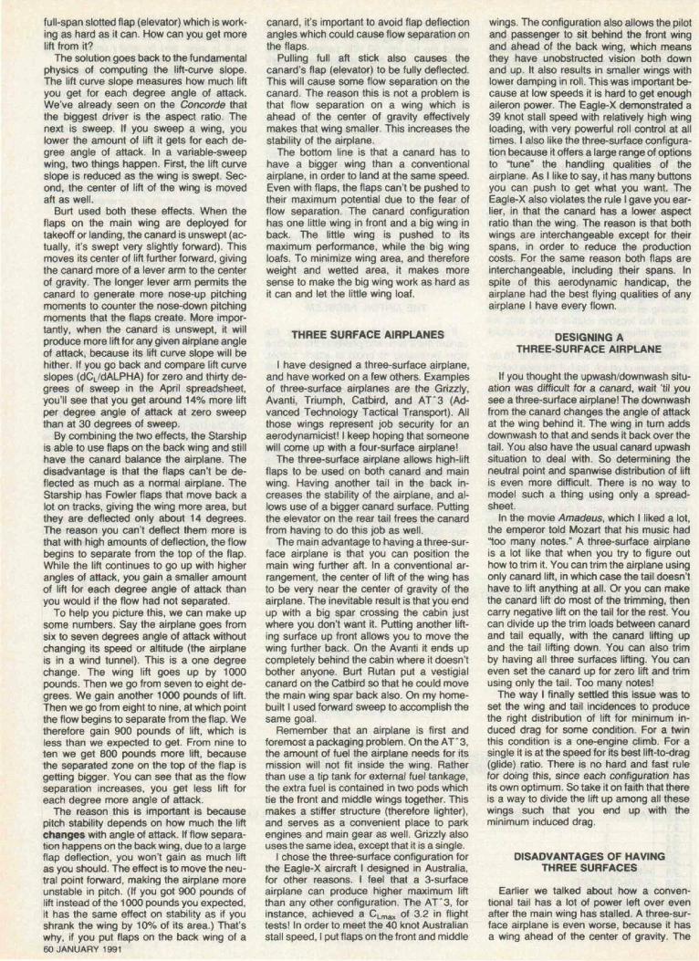
To help those of you who have wings likethis, I've written a very simple spreadsheet.This spreadsheet will calculate theaerodynamic center for you for a wing whichis not simply tapered. To use it, copy all thetitles and formulas from Figure 2 into yourspreadsheet program. When you're done, itshould look like Figure 3. Lotus 1-2-3 usersshould change all formulas beginning withan = to a ->-. The exceptions to this arethose formulas beginning with = SUM, whichshould be changed to (« SUM.
To use this spreadsheet, you divide yourwing into sections. Looking at Figure 1, yousee that I've projected the wing straight intothe body, where it intersects the body. Thismakes a rectangle which is 56.119 incheslong and 24.5 inches high. Outboard from
that is a small piece of wing whose leadingedge is straight, and whose trailing edge isswept forward. This piece runs from Buttline24.5 to Buttline 39.2. Finally. I squared offthe wingtip to approximate its area, and ranthe third piece from Buttline 39.2 to Buttline173.73. You also need to measure the Fuse-lage Station at the leading edges of eachspanwise panel boundary, which for myplane are at BLO, BL39.2. and BL173.73.
Next, you start with the innermost panel,and enter its root and tip chords, root and tipbuttlines, and the Fuselage Stations at theleading edge of the root and tip into thespreadsheet. It will then calculate the areaof this panel (actually twice the area, sinceyou are only modeling one-half the airplane),the spanwise location of its average chord,and the Fuselage Station of the quarterchord point on the average chord. You typethe panel area into column B, the Buttline ofthe MAC into column C, and the location ofthe quarter-chord into column D.
Then you repeat the above steps for theother panels. If your plane has only 2 panels,just enter 0 for the rest. Then enter thewingspan in feet into cell B13. The spread-sheet will report the average chord for yourairplane, the Buttline at which the averagechord acts, the leading edge Fuselage Sta-tion for the average chord, and the FuselageStation of the quarter chord along the aver-age chord. You can consider the FS of the1 /4 chord of the MAC to be the aerodynamiccenter of your airplane.
The sample spreadsheet in Figure 2shows the results for the airplane in Figure1. On Figure 1 I've measured out 72.841inches, which is the Buttline for the MACfrom the spreadsheet. Then I drew a linewhich is 39.817 inches long, starting at Fuse-lage Station 95.252. This puts the quarterchord at FS 105.206, which is what thespreadsheet calls for.
You may notice that the MAC does notactually correspond to a physical location onthe airplane. It's not supposed to. The pur-pose of this imaginary location is that it rep-resents a location at which the lift and dragforces of the wing can be considered to act.It is actually the average center of lift for yourwing. You can use the August spreadsheetto compute the exact location of theaerodynamic center along the average chordof the wing if you have the pitching momentsof your wing's airfoil. It will be at the 1 /4 chordpoint only if your airfoil has zero pitching mo-ments.
If you are building an elliptical wing, andare wondering what tip chord length to usein the spreadsheets, the answer is that youdon't! Instead, in the cell which computesthe taper ratio of your wing, you erase theformula in there, and replace it with .375.This will give you the right answer.
If you are building a delta wing, you cango ahead and specify a tip chord of zero.The formula will then correctly compute thecentroid of a triangle, which is what youwant.
NEXT TIME
The series concludes next month with areview of progress on my homebuilt. I'll showyou some tools that I used in its design. Youmay find some of them useful as well.
SPORT AVIATION 61