Embed Size (px)
Citation preview

Canadian Partnership for Quality Radiotherapy
Technical Quality Control Guidelines
for use of Positron Emission Tomography – Computed Tomography (PET/CT)
in Radiation Treatment Planning
A guidance document on behalf of:
Canadian Association of Radiation Oncology
Canadian Organization of Medical Physicists
Canadian Association of Medical Radiation Technologists
Canadian Partnership Against Cancer
March 31, 2021
PET.2021.03.01
www.cpqr.ca

Disclaimer All information contained in this document is intended to be used at the discretion of each individual
centre to help guide quality and safety program improvement. There are no legal standards supporting
this document; specific federal or provincial regulations and license conditions take precedence over the
content of this document. As a living document, the information contained within this document is
subject to change at any time without notice. In no event shall the Canadian Partnership for Quality
Radiotherapy (CPQR) or its partner associations, the Canadian Association of Radiation Oncology
(CARO), the Canadian Organization of Medical Physicists (COMP), and the Canadian Association of
Medical Radiation Technologists (CAMRT), be liable for any damages, losses, expenses, or costs
whatsoever arising in connection with the use of this document.

Technical Quality Control Guidelines for use of PET/CT in Radiation Treatment Planning Part of the Technical Quality Control Guidelines for Canadian Radiation Treatment Centres Suite
Page 3 of 31
PET.2021.03.01
Expert Reviewers Ran Klein, PhD
Department of Nuclear Medicine, The Ottawa Hospital, Ottawa, Ontario, Canada
Mike Oliver, PhD, MCCPM
Health Sciences North, Sudbury, Ontario, Canada
Dan La Russa, PhD, FCCPM
Radiation Medicine Program, The Ottawa Hospital, Ontario, Canada
John Agapito, MS, MCCPM
Windsor Regional Hospital, Windsor, Ontario, Canada
Stewart Gaede, PhD, MCCPM
London Health Sciences Centre, London, Ontario, Canada
Jean-Pierre Bissonnette, PhD, MCCPM, FCOMP
Princess Margaret Cancer Centre, Toronto, Ontario, Canada
Arman Rahmim, PhD, DABSNM
BC Cancer, Vancouver, British Columbia, Canada
Carlos Uribe, PhD, MCCPM
BC Cancer, Vancouver, British Columbia, Canada
Introduction
The Canadian Partnership for Quality Radiotherapy (CPQR) is an alliance amongst the three key national
professional organizations involved in the delivery of radiation treatment in Canada: the Canadian
Association of Radiation Oncology (CARO), the Canadian Organization of Medical Physicists (COMP), and
the Canadian Association of Medical Radiation Technologists (CAMRT), together with financial and
strategic backing from the Canadian Partnership Against Cancer (CPAC) which works with Canada’s cancer
community to reduce the burden of cancer on Canadians. The vision and mandate of the CPQR is to
support the universal availability of high quality and safe radiotherapy for all Canadians through system
performance improvement and the development of consensus-based guidelines and indicators to aid in
radiation treatment program development and evaluation.
This document contains detailed performance objectives and safety criteria for Positron Emission
Tomography for Radiation – Computed Tomography Treatment Planning (PET/CT for RTP). Please refer to
the overarching document Technical Quality Control Guidelines for Canadian Radiation Treatment

Technical Quality Control Guidelines for use of PET/CT in Radiation Treatment Planning Part of the Technical Quality Control Guidelines for Canadian Radiation Treatment Centres Suite
Page 4 of 31
PET.2021.03.01
Centres(1) for a programmatic overview of technical quality control, and a description of how the
performance objectives and criteria listed in this document should be interpreted.
In the RTP process, physiological information from positron emission tomography (PET) can be used to
inform target delineation and identify metabolically active regions for possible dose escalation.
Information from PET scans can also be used to help spare healthy tissue, further boosting the
probability of complication-free cure. PET based radiation treatment planning, however, is a relatively
new application that is not yet commonly utilized and requires quality control measures that are
incremental to that of routine diagnostic PET. This report reviews current quality control guidelines for
combined PET and x-ray CT for radiation treatment planning to produce a consolidated list of quality
control tests for PET-based radiation treatment planning. These incremental quality control activities are
relatively few and should not pose a major obstacle for expending the use of PET to radiation treatment
planning.
System Description Radiation therapy aims to accurately deposit a prescribed amount of radiation dose to target volumes
while sparing surrounding disease-free tissues. To achieve this goal, the radiological properties of the
patient anatomy must be accurately represented in the treatment planning system for dose-calculation
purposes. This anatomical information, along with delineated target and avoidance structures, is
routinely derived from CT-simulator images.
Modern, hybrid PET/CT system combine a PET sub-system to generate 3D images of functional
processes in the body and a co-registered CT sub-system. The CT generates attenuation images for
anatomical lesion localization while allowing for accurate photon attenuation correction of the PET
images. These hybrid systems are often equipped with fully diagnostic CT scanners that can also serve as
CT-simulators for RTP. With the addition of a flat table top and isocentre lasers, these hybrid systems
could well fulfill the requirements for CT simulation. Four perceived methods of PET/CT for RTP can be
envisioned in order of increasing technical complexity and treatment accuracy:
1) Side-by-side visualization of the diagnostic PET/CT data and a second CT-simulator image,
whereby the radiation oncologist manually define the treatment volumes on the CT-simulator
image using the PET/CT for guidance, as accurate image registration between the differing
patient postures may be challenging.(2) This method relies on existing practices and does not
leverage the full power of modern PET/CT for RTP and simulation. It is limited by low operator
reproducibility and accuracy.
2) Software based registration of the PET/CT study with the CT-simulator image to guide the
definition of treatment volumes.(3) In theory, this approach overcomes the above limitations.
Registration between images is usually achieved by affine registration between the two CTs and
is aided by consistent patient positioning in the RT posture. While deformable, non-rigid image
registration that can compensate for inconsistent patient positioning is an ongoing topic of

Technical Quality Control Guidelines for use of PET/CT in Radiation Treatment Planning Part of the Technical Quality Control Guidelines for Canadian Radiation Treatment Centres Suite
Page 5 of 31
PET.2021.03.01
research, routine clinical application is not yet widely feasible. Thus, inaccurate image
registration limits the accuracy of target delineation and subsequent treatment planning.
3) Acquisition of the PET/CT data with the patient in the RTP configuration and using this data for
target volume delineation and planning without the need for an additional CT-simulator image.
This method aims to fully exploit the information in PET/CT both for target delineation and RTP
dose calculations, but also requires a flat table top and a wall-mounted laser alignment system
be installed in the PET/CT imaging suite to accurately register the patient in the treatment
planning system and RT treatment machine. To date, widespread adoption of PET/CT-simulators
has been limited by workflow constraints and lack of reimbursement. Nevertheless, this method
is proposed as a feasible option due to the recent trend towards clinical utilization of PET/CT-
simulators, the decreased cost in FDG, and because the QC testing required for this method
encompasses the requirements for methods 1 and 2 above. It should be appreciated, however,
that incorporating the entire RT simulation process into the PET/CT image acquisition workflow,
which often includes the design and application of immobilization devices and patient indexing,
can result in prolonged PET/CT appointment times. This will undoubtedly reduce patient
throughput on PET imaging systems and risk increases to staff exposures (4).
4) A viable alternative to combining the RT simulation and PET/CT image acquisition processes is to
first perform RTP on a CT simulator and then replicate patient positioning in the PET/CT,
enabling accurate image registration through simple rigid transformations. These procedures
should include steps for converting the PET/CT system to accommodate a flat table top and
patient immobilization device that can be rapidly, consistently and safely deployed. Special
considerations should be given to potentially smaller bore sizes of PET/CT systems that may limit
patient positioning. This approach to acquiring PET/CT images will facilitate accurate image
registration for treatment planning CT images(5–7).
QA of PET/CT-simulators is largely similar to the QA of CT-simulators, with the addition of PET dedicated
QC tests. Since rigorous technical quality control guidelines for CT simulators have already been
established by CPQR (8) and are actively being maintained, supplementary guidelines should be created
for PET/CT with minimal duplication, to avoid inconsistencies as these guidelines evolve over time.
PET/CT devices are rarely dedicated to RT and therefore may reside in the diagnostic imaging
department (e.g. Nuclear Medicine or Radiology). Sharing of responsibilities between departments and
close coordination is essential to ensure quality of the overall PET/CT-simulator process.

Technical Quality Control Guidelines for use of PET/CT in Radiation Treatment Planning Part of the Technical Quality Control Guidelines for Canadian Radiation Treatment Centres Suite
Page 6 of 31
PET.2021.03.01
Glossary
CT – x-ray computed tomography
FWHM – Full Width at Half Maximum
FWTM – Full Width at Tenth Maximum
NECR – Noise Equivalent Count Rate
PET – Positron emission tomography
QC – quality control
ROI – Region of Interest
RT – Radiation treatment
RTP – Radiation treatment planning
TQC – Technical quality control (documents)
Related Technical Quality Control Guidelines Performance testing Performance tests should be referred to when selecting a system, when performing acceptance
evaluation of newly installed equipment, and prior to the end of a manufacturer’s warranty period. The
National Electrical Measurements Association (NEMA) has developed standard NU-2-2012 (10) which
has become the de facto standard for evaluating the performance of PET systems. The standard
describes equipment and procedures for measuring system performance parameters including spatial
resolution, scatter fraction, count losses, random events measurement, activity sensitivity, corrections
accuracy and image quality. The NEMA standard was updated to version NU-2-2018 (11) adding two
new procedures to assess coincidence timing resolution on PET systems with time-of-flight capability,
and to assess co-registration accuracy of hybrid PET/CT systems; the latter is of particular interest in
using PET for RTP. Likewise, performance testing of CT equipment are detailed by the American
Association of Physicists in Medicine (AAPM) (12), International Electrotechnical Commission (IEC) (13)
and other similar professional body recommendation documents. These tests are also summarized in
(14).
Acceptance Testing and Commissioning Newly acquired or substantially modified PET/CT systems should be tested to ensure performance
complies with vendor and tender stated specifications(15,16). Through active participation in the
acceptance testing, users may also become familiar with the system. Commissioning follows acceptance
testing with a comprehensive battery of performance tests to establish base-line performance metrics

Technical Quality Control Guidelines for use of PET/CT in Radiation Treatment Planning Part of the Technical Quality Control Guidelines for Canadian Radiation Treatment Centres Suite
Page 7 of 31
PET.2021.03.01
against which subsequent tests may be compared to ensure stable and acceptable performance of the
system over its lifetime.
System Upgrades and Maintenance Special consideration should be given in the case of a PET/CT system servicing and upgrades. Acceptance
or preventive maintenance tests provided by the PET/CT manufacturer under an institutional service
contract agreement should ensure that the PET/CT system is at optimal functionality. However, monthly
tests should be performed after any hardware upgrade and monthly/annual QC should be done after
PET/CT console software upgrade.
Routine QC Routine QC is performed to ensure system stability from time of commissioning and to proactively
determine the need for service. Periodic (e.g. daily, monthly, quarterly) QC tests are typically defined by
the manufacturer and may differ from general guidelines due to technology (e.g. solid-state vs
photomultiplier tube-based detection) and feasibility considerations (e.g. automated QC). Routine QC
guidelines have been established by multiple professional groups with a consensus statement on
Diagnostic Imaging Requirements put out by the Joint Commission on the Accreditation of Healthcare
Organizations as an umbrella list of QA requirements (9). The Canadian Partnership for Quality
Radiotherapy has established its own Technical Quality Control (TQC) Guidelines as summary standards
of test frequency and tolerances. (17)
Recommendations from major international professional bodies (listed in Table 1) were included in this
review. A summary of recommended routine QC activities and frequencies is summarized in the Test
Tables section along with references in which greater details on the QC test may be found. Tolerances
from TQCs were used if available, otherwise the strictest values from the reviewed literature were
adopted. The list is intended to serve as a guideline and may not be optimal for all equipment types and
all applications. For comprehensive instructions for performing PET/CT QA, the reader is referred to
references (14,18).
Table 1: List of related quality control references reviewed
Title Revision
year
Professional Body Modality Reference
Task Group 174 Report: Utilization of
[18F]Fluorodeoxyglucose Positron Emission
Tomography ([18F]FDG-PET) in Radiation
Therapy
2019 American
Association of
Physicists in
Medicine
PET-CT (7)
Technical Quality Control Guidelines for
Computed Tomography Simulators
2016 Canadian
Partnership for
Quality
Radiotherapy
CT-
simulator
(8)

Technical Quality Control Guidelines for use of PET/CT in Radiation Treatment Planning Part of the Technical Quality Control Guidelines for Canadian Radiation Treatment Centres Suite
Page 8 of 31
PET.2021.03.01
Technical standard for medical nuclear
physics performance monitoring of PET
imaging equipment
2016 American College
of Radiologists &
American
Association of
Physicists in
Medicine
PET (18)
Diagnostic Imaging Requirements 2015 Joint Commission
on the
Accreditation of
Healthcare
Organizations
PET, CT,
MRI, NM
(9)
Routine quality control recommendations
for nuclear
medicine instrumentation
2010 European
Association of
Nuclear Medicine
PET, Dose
calibrator
(19)
PET/CT and radiotherapy: data transfer,
radiotherapy workflow and quality
assurance
2010 - PET, CT,
RTP
(2)
Quality assurance for PET and PET/CT
systems
2009 International
Atomic Energy
Agency
PET, CT (14)
Quality assurance of PET/CT for radiation
therapy
2008 - PET, CT,
RTP
(20)
Routine quality control of clinical nuclear
medicine instrumentation: A brief review
2008 - PET, CT,
Dose
calibrator
(21)
Quality assurance for computed-
tomography simulators and the computed-
tomography-simulation process: Report of
the AAPM Radiation Therapy Committee
Task Group N. 66
2003 American
Association of
Physicists in
Medicine
CT-
simulator
(22)
In order to comprehensively assess the use of PET/CT for RTP performance, additional tests, as outlined
in related CPQR Technical Quality Control (TQC) guidelines must also be completed and documented, as
applicable. Related TQC guidelines, available at cpqr.ca, include:
• Treatment Planning Systems
• Computed Tomography Simulators
• Data Management Systems
Technical Quality Control Guidelines for use of PET/CT in Radiation Treatment Planning Part of the Technical Quality Control Guidelines for Canadian Radiation Treatment Centres Suite
Page 9 of 31
PET.2021.03.01
TQC guidelines are referred to throughout as a primary source to avoid conflicting instructions as these
live documents are updated.
The QA program should be overseen by trained medical physicist(s) with expertise in diagnostic imaging,
nuclear medicine, and RT. Frequent QC tests may be delegated to trained technologists, but results
should be reviewed by a physicist in a timely manner to identify equipment that does not meet
operating specifications.
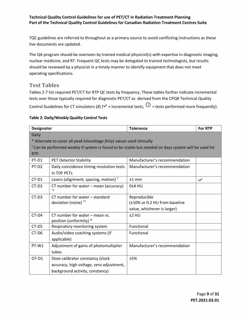
Test Tables Tables 2-7 list required PET/CT for RTP QC tests by frequency. These tables further indicate incremental
tests over those typically required for diagnostic PET/CT as derived from the CPQR Technical Quality
Control Guidelines for CT simulators (8) ( = incremental tests, = tests performed more frequently).
Table 2: Daily/Weekly Quality Control Tests
Designator Tolerance For RTP
Daily
* Alternate to cover all peak kilovoltage (kVp) values used clinically Ϯ Can be performed weekly if system is found to be stable but needed on days system will be used for
RTP.
PT-D1 PET Detector Stability Manufacturer’s recommendation
PT-D2 Daily coincidence timing resolution tests
in TOF PETs
Manufacturer’s recommendation
CT-D1 Lasers (alignment, spacing, motion) Ϯ ±1 mm CT-D2 CT number for water – mean (accuracy)
*Ϯ 0±4 HU
CT-D3 CT number for water – standard deviation (noise) *Ϯ
Reproducible (±10% or 0.2 HU from baseline
value, whichever is larger)
CT-D4 CT number for water – mean vs. position (uniformity) *
±2 HU
CT-D5 Respiratory monitoring system Functional
CT-D6 Audio/video coaching systems (if
applicable)
Functional
PT-W1 Adjustment of gains of photomultiplier
tubes
Manufacturer’s recommendation
OT-D1 Dose calibrator constancy (clock
accuracy, high voltage, zero adjustment,
background activity, constancy)
±5%

Technical Quality Control Guidelines for use of PET/CT in Radiation Treatment Planning Part of the Technical Quality Control Guidelines for Canadian Radiation Treatment Centres Suite
Page 10 of 31
PET.2021.03.01
Notes on Daily/Weekly Tests
Daily/Weekly
QC Tests
This refers to daily incidence of PET and CT daily and weekly quality control.
PT-D1 – 2
and PT-W1
As per manufacturer instructions, these tests are typically semi-automated and only
require confirmation that the test has passed, and no visual artifacts are visible in the
recorded sinograms. The tests measure the stability of the PET detectors. On scanners
with TOF, it measures the capability of the system to estimate the difference in arrival
times of the two annihilation photons.
The weekly test updates the detector gains to compensate for changes in the crystals’
behavior over time. See references (14) and (20) for more details.
CT-D1 - 6 Refer to TQC for Computed Tomography Simulators (8).
OT-D1 As per manufacturer instructions, follow the daily quality control procedure using a long-
lived radionuclide source (e.g. 137Cs) to test accuracy and stability. (19)
Table 3: Monthly Quality Control Tests
Designator Tolerance For RTP
Monthly (or after system maintenance) ‡ Perform whenever tabletop is removed and reinstalled
CT-M1 Tabletop level accuracy‡ ±2 mm CT-M2 Lasers (orthogonality/orientation) ± 1mm over the length of laser
projection
CT-M3 Tabletop displacement accuracy‡ ±1 mm
G-M1 Records Complete
Notes on Monthly Tests
CT-M1 - 3 Refer to TQC for Computed Tomography Simulators (8).
G-M1 Documentation relating to the daily quality control checks, preventive maintenance,
service calls, and subsequent checks must be complete, legible, and the operator
identified. (16)

Technical Quality Control Guidelines for use of PET/CT in Radiation Treatment Planning Part of the Technical Quality Control Guidelines for Canadian Radiation Treatment Centres Suite
Page 11 of 31
PET.2021.03.01
Table 4: Quarterly Quality Control Tests
Designator Tolerance For RTP
Quarterly (or after system maintenance)
PT-Q1 PET System normalization and
calibration
Visual acceptance.
The new calibration should be
checked with a reconstructed
image of the flood phantom
applying all the corrections. The
mean measured SUV in a region of
10 cm in the center of the phantom
should be 1.0 ± 0.1.
Calibration constant change <5%
from previous. (23,24)
PT-Q2 Uniformity of reconstructed PET image Within 5% of baseline value
PT-Q3 PET and CT registration ±1 pixel or ±1 mm
CT-Q1 CT number accuracy (>4 materials) ±5 HU
CT-Q2 3D low contrast resolution Reproducible
(set action level at time of
acceptance)
CT-Q3 3D high contrast spatial resolution (at
10 and 50% modulation transfer
function [MTF])
Reproducible
(±0.5 lp/cm or ±15% of the
established baseline value,
whichever is greater)
CT-Q4 Slice thickness (sensitivity profile) Reproducible
(±0.5 mm from baseline for slices
≥2 mm
±50% from baseline for slices of 1
to 2 mm
±0.5 mm from baseline for slices <1
mm)
CT-Q5 Amplitude and periodicity of motion
surrogate with monitoring software
and/or CT console
1 mm, 0.1 s
CT-Q6 4D-CT reconstruction
Functional
CT-Q7 Amplitude of moving target(s)
measured with 4D-CT
<2 mm

Technical Quality Control Guidelines for use of PET/CT in Radiation Treatment Planning Part of the Technical Quality Control Guidelines for Canadian Radiation Treatment Centres Suite
Page 12 of 31
PET.2021.03.01
CT-Q8 Spatial integrity and positioning of
moving target(s) at each 4D respiratory
phase
2 mm (FWHM) difference from
baseline measurement (increased
for amplitudes larger than 2 cm)
CT-Q9 Mean CT number and standard
deviation of moving target(s) at each
respiratory phase
(±10 HU) and (±10%) from baseline
measurement (increased for
amplitudes larger than 2 cm)
CT-Q10 4D-CT intensity projection image
reconstruction (Avg, MIP, MinIP)
2 mm (FWHM) difference from
baseline measurement (increased
for amplitudes larger than 2 cm)
CT-Q11 4D data import to treatment planning
system
Functional
OT-Q1 Dose calibrator linearity Manufacturer’s recommendation
Notes on Quarterly Tests
PT-Q1 This test measures the crystal efficiency and is used to correct for crystal non-
uniformities that degrade the images. The scanner is also cross-calibrated with the dose
calibrator to ensure that SUV calculations are accurate, and the images are
quantitative.(14)
The test is performed using a cylindrical uniform phantom of known activity
concentration (depending on the manufacturer’s recommendations it can be a pre-
manufactured 68Ge phantom or a fillable one with 18F). The normalization data is
acquired according to the manufacturer’s instructions. A calibration factor relating the
detected events to the known activity concentration is also calculated. The test passes
when a reconstructed image using the new established normalization and calibration
factor parameters is visually uniform, and the measured SUVmean in a big field of view
inside the phantom is close to 1. Data should also be compared with previous
measurements to detect big shifts in calibration, which could indicate procedural errors
in the test.(23,24)
PT-Q2 The cylindrical phantom from the PT-Q1 test is used to measure the response of the
system to the homogeneous activity distribution.(14) An image of the phantom is
reconstructed with all the corrections enabled (i.e. deadtime, attenuation, scatter, etc)
and using the parameters of the institution’s standard clinical protocol. For each
transaxial slice in the image, a grid of 10 mm x 10 mm squares is drawn. The maximum,
minimum, and mean concentration 𝑐 of each grid 𝑘 in each of the 𝑖 image slices is
recorded. The maximum value of non-uniformity across all images (NUi) should be
reported where:
Technical Quality Control Guidelines for use of PET/CT in Radiation Treatment Planning Part of the Technical Quality Control Guidelines for Canadian Radiation Treatment Centres Suite
Page 13 of 31
PET.2021.03.01
𝑁𝑈𝑖 = 𝑀𝐴𝑋
{
𝑀𝐴𝑋(𝑐𝑘) − 𝐴𝑉𝐸(𝑐𝑘)
𝐴𝑉𝐸(𝑐𝑘)× 100
𝐴𝑉𝐸(𝑐𝑘) −𝑀𝐼𝑁(𝑐𝑘)
𝐴𝑉𝐸(𝑐𝑘)× 100
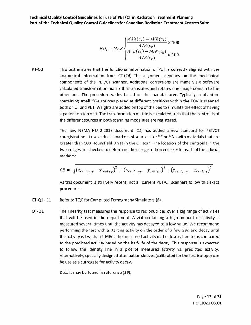
PT-Q3 This test ensures that the functional information of PET is correctly aligned with the
anatomical information from CT.(14) The alignment depends on the mechanical
components of the PET/CT scanner. Additional corrections are made via a software
calculated transformation matrix that translates and rotates one image domain to the
other one. The procedure varies based on the manufacturer. Typically, a phantom
containing small 68Ge sources placed at different positions within the FOV is scanned
both on CT and PET. Weights are added on top of the bed to simulate the effect of having
a patient on top of it. The transformation matrix is calculated such that the centroids of
the different sources in both scanning modalities are registered.
The new NEMA NU 2-2018 document (11) has added a new standard for PET/CT
coregistration. It uses fiducial markers of sources like 18F or 22Na with materials that are
greater than 500 Hounsfield Units in the CT scan. The location of the centroids in the
two images are checked to determine the coregistration error CE for each of the fiducial
markers:
𝐶𝐸 = √(𝑥𝑐𝑒𝑛𝑡𝑃𝐸𝑇 − 𝑥𝑐𝑒𝑛𝑡𝐶𝑇)2+ (𝑦𝑐𝑒𝑛𝑡𝑃𝐸𝑇 − 𝑦𝑐𝑒𝑛𝑡𝐶𝑇)
2+ (𝑧𝑐𝑒𝑛𝑡𝑃𝐸𝑇 − 𝑧𝑐𝑒𝑛𝑡𝐶𝑇)
2
As this document is still very recent, not all current PET/CT scanners follow this exact
procedure.
CT-Q1 - 11 Refer to TQC for Computed Tomography Simulators (8).
OT-Q1 The linearity test measures the response to radionuclides over a big range of activities
that will be used in the department. A vial containing a high amount of activity is
measured several times until the activity has decayed to a low value. We recommend
performing the test with a starting activity on the order of a few GBq and decay until
the activity is less than 1 MBq. The measured activity in the dose calibrator is compared
to the predicted activity based on the half-life of the decay. This response is expected
to follow the identity line in a plot of measured activity vs. predicted activity.
Alternatively, specially designed attenuation sleeves (calibrated for the test isotope) can
be use as a surrogate for activity decay.
Details may be found in reference (19).
Technical Quality Control Guidelines for use of PET/CT in Radiation Treatment Planning Part of the Technical Quality Control Guidelines for Canadian Radiation Treatment Centres Suite
Page 14 of 31
PET.2021.03.01
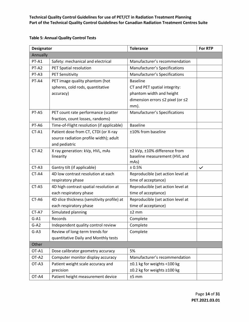
Table 5: Annual Quality Control Tests
Designator Tolerance For RTP
Annually
PT-A1 Safety: mechanical and electrical Manufacturer’s recommendation
PT-A2 PET Spatial resolution Manufacturer’s Specifications
PT-A3 PET Sensitivity Manufacturer’s Specifications
PT-A4 PET image quality phantom (hot
spheres, cold rods, quantitative
accuracy)
Baseline
CT and PET spatial integrity:
phantom width and height
dimension errors ≤2 pixel (or ≤2
mm).
PT-A5 PET count rate performance (scatter
fraction, count losses, randoms)
Manufacturer’s Specifications
PT-A6 Time-of-Flight resolution (if applicable) Baseline
CT-A1 Patient dose from CT, CTDI (or X-ray
source radiation profile width); adult
and pediatric
±10% from baseline
CT-A2 X ray generation: kVp, HVL, mAs linearity
±2 kVp, ±10% difference from baseline measurement (HVL and mAs)
CT-A3 Gantry tilt (if applicable) ± 0.5% CT-A4 4D low contrast resolution at each
respiratory phase
Reproducible (set action level at
time of acceptance)
CT-A5 4D high contrast spatial resolution at
each respiratory phase
Reproducible (set action level at
time of acceptance)
CT-A6 4D slice thickness (sensitivity profile) at
each respiratory phase
Reproducible (set action level at
time of acceptance)
CT-A7 Simulated planning ±2 mm
G-A1 Records Complete
G-A2 Independent quality control review Complete
G-A3 Review of long-term trends for
quantitative Daily and Monthly tests
Complete
Other
OT-A1 Dose calibrator geometry accuracy 5%
OT-A2 Computer monitor display accuracy Manufacturer’s recommendation
OT-A3 Patient weight scale accuracy and
precision
±0.1 kg for weights <100 kg
±0.2 kg for weights ≥100 kg
OT-A4 Patient height measurement device ±5 mm

Technical Quality Control Guidelines for use of PET/CT in Radiation Treatment Planning Part of the Technical Quality Control Guidelines for Canadian Radiation Treatment Centres Suite
Page 15 of 31
PET.2021.03.01
Notes on Annual Tests
PT-A1 This test ensures that the PET/CT scanner mechanical and electrical components are
operating as indicated by the manufacturer. Follow any manufacturer’s
recommendations and inspect the housing, bed motion, controls, connectors, and any
accessories that are connected to the scanner. (14,18,25)
PT-A2 The aim of this test is to measure the tomographic resolution in air and ensure that is
not affected by the acquisition or reconstruction. The procedure involves scanning 3-
point sources of 18F that are prepared from a high activity concentration in capillary
tubes. The tubes are placed in three different positions within the FOV but are always
in the same longitudinal plane. The positioning of the sources within the FOV has been
updated between different versions of the NEMA standards so is important to check
with the manufacturer to determine which version of the standards should be followed.
The acquired images are reconstructed with a pixel size of 1/3 of the expected scanner
resolution (typically less than 1.5 mm per pixel). Profiles of the sources are generated in
all the different directions. The full width at half maximum (FWHM) and full width at
tenth of maximum (FWTM) are calculated. The radial and tangential resolutions are
averaged. The FWHM should not exceed the specifications provided by the
manufacturer. (11,14,18)
PT-A3 This test determines the rate of detected true coincidences per unit of radioactivity
concentration (e.g. kcps/MBq) for a standard line source configuration. Several scans of
a line source with different aluminum sleeves that increase the thickness of absorbing
material are used to extrapolate the value to the one where no attenuating material is
present. The procedure is performed at the center of the FOV and at 10 cm from the
central axis. The sensitivity is expected to be equal or greater than the specified by the
scanner manufacturer. (11,14,18)
PT-A4 The purpose of this test is to generate images that simulate a real patient scan with hot
and cold lesions and with scatter from outside of the FOV. The quality of the image is
assessed from the contrast and background variability, accuracy of the attenuation and
scatter corrections, and from the accuracy of the radioactivity quantification. The
procedure involves scanning the NEMA IEC body phantom that includes six spheres of
different sizes.
The two biggest spheres are filled with water that does not contain radioactivity; while
the other four are filled with a solution that has a concentration of 8 times the one in
the background (some manufacturers also suggest using a 4:1 ratio). A line source is
placed inside a cylindrical plastic phantom to generate some scatter out of the FOV. The

Technical Quality Control Guidelines for use of PET/CT in Radiation Treatment Planning Part of the Technical Quality Control Guidelines for Canadian Radiation Treatment Centres Suite
Page 16 of 31
PET.2021.03.01
images should be reconstructed as recommended by the manufacturer for a standard
whole-body protocol.
The slice in which the contrast of cold and hot spheres is highest is selected to draw
regions of interest around each of the spheres. The diameters of the ROIs should be as
close to the inner diameter of the sphere as possible. Concentric ROIs of the same sizes
(both cold and hot spheres) are drawn on the same slice at 12 background regions (see
NEMA standards for location of ROIs). The same ROIs are then copied to four
neighboring slices (~±1 and ±2 cm) giving a total of 60 background ROIs for each size of
sphere; 12 on each of the 5 slices. The average number of counts in each hot,
background, and cold spheres in combination with the known activity concentrations
are used to calculate the contrast and background variability.
An ROI with a diameter of 3.0 cm is drawn on the lung insert for each of the slices. If the
scatter and attenuation correction are perfect, this value is expected to be close to zero.
Another 12 circular 3.0 cm diameter ROIs placed over the background region are used
to calculate a percentage relative error for the lung insert and for each slice. This is the
ratio of the average counts in the lung ROI to the corresponding average in the
background for the 12 ROIs.
Lastly, accuracy in activity quantification is measured from the known activity in the
background at the time of the phantom filling procedure and comparing it to the
average radioactivity concentration measured from the image by averaging the 12 3.7
cm diameter background ROIs.
Using a fused image display, ensure accurate registration between PET and CT images.
Measure the width and height of the phantom shell on the CT image and ensure that
they agree with the physical measurements within 2 pixel width (or 2 mm) to ensure
spatial integrity of both PET and CT modalities.
See references (11,14,18) for further details.
PT-A5 This test measures the contribution of scatter, count losses, and randoms to the image.
All of these effects degrade the image quality and quantification accuracy. A small
scatter fraction (ratio of scatter photons to the sum of true coincidences and scatter) is
desired. The count rate performance provides information regarding the quantitative
accuracy at low and high-count rates. The noise equivalent count rate (NECR) is typically
used to represent the count rate performance as a function of the activity
concentration. The peak NECR and the corresponding activity concentration serve as a
guide to optimize the injected activity to patients. The calculation assumes Poisson

Technical Quality Control Guidelines for use of PET/CT in Radiation Treatment Planning Part of the Technical Quality Control Guidelines for Canadian Radiation Treatment Centres Suite
Page 17 of 31
PET.2021.03.01
statistics, and considers the contribution of true, scattered, and random events to the
total coincidence rate.
The method of measurement involves a 70 cm long line source that is placed inside and
off-centre of a plastic cylinder. The manufacturer’s specifications for the initial
radioactivity concentration within the line source should be followed. Different
acquisitions are taken at intervals of less than half of the half-life of the radioisotope
(e.g. 18F), but with a higher frequency around the peak of the NECR curve. Each
acquisition has a duration that should be less than ¼ of the half-life of the radioisotope.
The analysis might be slightly different between systems that allow the measurement
of randoms compared to the ones that do not.
Pixels that are more than 12 cm away from the center of each sinogram (i.e. one
sinogram per acquisition) are set to zero. Then, the maximum pixel on each projection
(row) of the sinogram is shifted to the center of the sinogram and all the projections are
added. A profile of total counts as a function of distance from the center of the sinogram
is made. The sum of scatter and randoms, the total counts, and the unscattered counts
can be determined from that profile. The scatter fraction is then calculated for each
slice and each acquisition. The NECR for each acquisition 𝑗 is calculated based on the
trues, total, and randoms of each slice 𝑖 as:
𝑁𝐸𝐶𝑅𝑖,𝑗 =𝑅𝑡𝑖,𝑗2
(𝑅𝑡𝑜𝑡𝑖 ,𝑗+ 𝜅𝑅𝑟𝑖,𝑗)
where 𝑅𝑡 is the rate of true coincidences, 𝑅𝑡𝑜𝑡 is the total count rate, and 𝑅𝑟 represents
the randoms count rate. The value of 𝜅 is given according to
𝜅 = {0 → 𝑒𝑞𝑢𝑖𝑝𝑚𝑒𝑛𝑡 𝑤𝑖𝑡ℎ𝑜𝑢𝑡 𝑟𝑎𝑛𝑑𝑜𝑚𝑠 𝑠𝑢𝑏𝑡𝑟𝑎𝑐𝑡𝑖𝑜𝑛1 → 𝑒𝑞𝑢𝑖𝑝𝑚𝑒𝑛𝑡 𝑤𝑖𝑡ℎ 𝑟𝑎𝑛𝑑𝑜𝑚𝑠 𝑠𝑢𝑏𝑡𝑟𝑎𝑐𝑡𝑖𝑜𝑛
The total system NECR for an acquisition 𝑗 is the sum of 𝑁𝐸𝐶𝑅𝑖,𝑗 over all the slices 𝑖.
The scatter fraction, peak NECR, and the radioactivity concentration to reach the peak
NECR should meet the manufacturers specifications.
See references (11,14,18) for further details.
PT-A6 This test determines the capability of the system to measure the difference in arrival
time of two coincidence events. Follow the manufacturer’s recommendations to
perform this test. A typical measurement uses a line source of 18F in an aluminum tube
positioned at the center of the scanner. The system records coincidences with time of
arrival and generates some histograms for it. The timing resolution is calculated as the

Technical Quality Control Guidelines for use of PET/CT in Radiation Treatment Planning Part of the Technical Quality Control Guidelines for Canadian Radiation Treatment Centres Suite
Page 18 of 31
PET.2021.03.01
FWHM on this histogram. The timing resolution should not exceed the manufacturer’s
specifications. (11,14,18)
CT-A1 - 7 Refer to TQC for Computed Tomography Simulators (8) and (22).
GA1 – 3 Refer to TQC for Computed Tomography Simulators (8) and (16).
OT-A1 The dose calibrator geometry test allows determining if the correct activity values are
measured regardless of the sample size geometry. For this, all the different syringes and
vials used to draw-up injected doses are tested. For each of the volumes, an initial value
of activity is measured. This is then followed by subsequent measurements in which a
saline solution or water is added to the syringe/vial to increase the volume. In all cases,
the activity is expected to be within 5% of the initial values. If variations >±5% exist
derive a calibration factor to be applied clinically. Ensure no change from baseline.
Likewise, using a syringe test stability of the activity reading as the source is gradually
withdrawn from the ionization chamber. Ensure that activity readings are consistent
across >5 cm of displacement, and that response is consistent with baseline.
Details may be found in reference (19).
OT-A2 Clinical computer monitor displays should be tested and calibrated at least annually
using a dedicated light measurement device and according to its manufacturer
procedure. As a minimum, displays that have obvious discoloring, non-uniform
luminance >30% or that deviate from DICOM luminance response accuracy by >10% and
cannot be calibrated should be replaced. (26)
OT-A3 No regulatory guidelines or standards could be found for quality control of medical
weight scales. But vendor provided instructions require testing using standard weights
on the order of typical patient weights (e.g. 100 kg). Testing should be performed on an
annual basis, after relocating the device or after service. Errors should not exceed 0.1
kg for weights <100kg of 0.2 kg for larger weights.
OT-A4 No guidelines or standards could be found for quality control of height measurements
devices. Accuracy should be tested annually, after relocating or after service using an
independent measuring device such as a measuring tape.

Technical Quality Control Guidelines for use of PET/CT in Radiation Treatment Planning Part of the Technical Quality Control Guidelines for Canadian Radiation Treatment Centres Suite
Page 19 of 31
PET.2021.03.01
Table 6: Patient-Specific Quality Control Tests
Designator Tolerance For RTP
Case-by-Case
PS1 Correct patient Matched patient identifying information
PS2 Correct patient preparation Matched to requisition
PS3 Correct patient positioning Matched to treatment plan
PS4 Correct imaging protocol and parameters
Matched to requisition and technologist worksheet
PS5 PET/CT Image registration Adequate co-registration
PS6 Image quality Diagnostic image quality
Notes on Patient-Specific Tests
At least three forms should be filled to ensure that the PET/CT procedure is going to be performed
optimally:
1. A screening form should be filled by the booking clerk ensuring that contains information
regarding patient medication, diabetes, claustrophobia, concerns lying flat for the PET/CT scan,
and for females, whether they are pregnant or breastfeeding.
2. A questionnaire form to be filled by the patient and to be presented on the day of the
appointment. This form should include some questions regarding the patient’s clinical history
(e.g. asthmatic, diabetic, smoke status). It should contain information about any implants or
other foreign objects within the patient’s body. In addition, it should include a small
questionnaire in the type of “checkboxes” to ensure that the patient has fasted before the
appointment (if required), is well hydrated, and has listed his current medications.
3. A PET/CT technologist worksheet that includes patient information such as name, date of birth,
and age. The technologists should record the patient’s weight and height, glucose level, allergies,
radioisotope to be administered, and should record the initial activity in the syringe, and the
residual after injection with its respective times of measurement. Additionally, the volume of
radiotracer and the site of injection should also be recorded. The scan protocol, including the
scan range (e.g. whole-body vs. vertex to thighs) should be pre-established before the patient
arrives at the facility and should be written in this technologist worksheet.
These forms should be used to ensure that the tests from Table and described below are correctly
performed.
Technical Quality Control Guidelines for use of PET/CT in Radiation Treatment Planning Part of the Technical Quality Control Guidelines for Canadian Radiation Treatment Centres Suite
Page 20 of 31
PET.2021.03.01
PS1 The name, date of birth, and other medical information should be checked with the
patient prior to beginning any procedure. At least two extra patient provided information
should match the medical requisition. (27)
PS2 Refer to the PET/CT technologists form and check that the imaging protocol and patient
preparation, conform to requisition. If the patient is unable to comply, special
accommodations may be required. If ambiguity exists, consult with the reporting
physicians and/or on service referring physician. (27)
PS3 Ensure that patient positioning conforms to treatment plan including use of all
immobilization devices and appropriate position indexing. These parameters should be
available in the technologist worksheet form. Perform the scout/topogram acquisition
and ensure that positioning and FOV are set as defined in the technologist worksheet
before continuing the PET/CT acquisition. (7)
PS4 Image acquisition parameters should be preconfigured on the acquisition system for all
common procedures and documented in a clinical protocol. The scanning protocol should
be written in advance in the technologist’s worksheet. Before performing the scout
acquisition, the selection of the protocol should be checked to match what is specified in
the technologist form. If deviations from preconfigured protocols are required, these
should be documented by the technologists. (27)
PS5 Accurate registration between PET and CT scans must be ensured during PET image
reconstruction. If significant patient motion has occurred between scans (especially at
targets of interest) repetition of scans on a limited FOV should be considered. Rigid
motion correction can be considered if appropriate, but small corrections are
discouraged, as they typically exacerbate misregistration. This can be tested by
generating fused images of PET and CT and visually inspecting for mismatch artifacts. The
patient should not be removed from the scanner until the images have been checked to
avoid having to obtain an extra CT following the ALARA principle. (27)
PS6 Global image quality QC tests include checking for artifacts, verifying FOV coverage,
appropriate CT contrast (if applicable), and that correct series description names have
been set on the images so that nuclear medicine physicians can easily understand what
they are looking at. (27)
Ancillary equipment PET images are typically reported as standard uptake values (SUV) which have been shown to be accurate
within ±10% across a wide range of scanner models with appropriate QA and method standardization.
(28) Because SUV is computed based on patient weight, periodic QA should be applied to patient weight

Technical Quality Control Guidelines for use of PET/CT in Radiation Treatment Planning Part of the Technical Quality Control Guidelines for Canadian Radiation Treatment Centres Suite
Page 21 of 31
PET.2021.03.01
scales as recommended by the vendor.(7) Accuracy and precision on the order of ±1 kg corresponds to 1-
2% patient weight error and is on par with clinical sources of variability including patient clothing, bowel
content and hydration state, but ±0.2 kg is readily achievable with clinical devices and routine QC.
Likewise, PET images are often scaled to standard uptake based on lean-body mass (SUL), which are
computed based on patient height. Height measurement apparatuses should be accurate to within 5 mm.
Dose calibrators are used to measure the patient administered activities which factors into the SUV
calculation and they serve as a reference for calibration of the PET system. Therefore, they must undergo
routine QC to ensure consistency. If multiple dose calibrators are in use, cross calibration must also be
ensured. Vendor recommendations should be followed, while professional society guidelines also layout
periodic QC including consistency, accuracy, linearity, and geometric and positioning sensitivity testing
(19).
Synchronization of clocks between dose calibrators and PET imaging devices is required for accurate
radionuclide decay correction and may be aided by automated device clock synchronization with a
centralized time server. Regardless, daily QC of dose calibrator and PET times is recommended, with an
emphasis when adjusting to daylight savings times.
Image transfer and compatibility Widespread adoption of DICOM standards for image and RTP transfer has aided compatibility between
imaging, diagnostic visualization and treatment planning systems. Target volumes can therefore be
delineated on either diagnostic imaging or treatment planning workstations depending on the preferred
tools and workflow. Nevertheless, commissioning of new systems should entail validation of proper data
transfer including specific emphasis on image orientation, pixel size, spatial positioning offsets and image
unit scaling (e.g. SUV). Validations should replicate the clinical workflow and can utilize phantom scans or
a patient scans augmented with physical markers that are visible in the image. Marker locations, sizes and
separation can be measured in images and validated against the empirical setup. Suitable markers include:
1) Radioactive point sources (e.g. 22Na)
2) Radioactive dilution standards (e.g. sealed vials with known dilutions of FDG) for validating activity
quantification.
3) Thin metal wires that are visible on CT, but do not introduce artifacts.
Commissioning acceptance testing and routine QC testing for RTP systems are detailed in the AAPM TG-
53 report (29) and in the IAEA Technical document N. 1583 (15).
Image reconstruction and processing Image reconstruction and processing parameters can influence image characteristics including target to
background uptake ratio, spatial resolution and noise. These in turn may influence the perceived target
size and intensity. For consistent volume delineation, image reconstruction and processing methodologies
should be carefully derived, validated and preserved. As patients may be imaged on different scanners
during the course of their treatment a need to harmonize image reconstruction and processing across the

Technical Quality Control Guidelines for use of PET/CT in Radiation Treatment Planning Part of the Technical Quality Control Guidelines for Canadian Radiation Treatment Centres Suite
Page 22 of 31
PET.2021.03.01
patient catchment region is ideal, especially for quantitative assessment of tumor response to treatments
including RT. This Changes to methodology should be coordinated between the imaging and radiation
therapy teams. Likewise, the use of institutionally standardized default image display parameters (e.g.
colormaps, window/level and image fusion level) is recommended.
Acknowledgements
CPQR would like to thank the many people who participated in the production of this guideline. These
include: Michelle Nielsen and David Sasaki (associate editors); the Quality Assurance and Radiation Safety
Advisory Committee; the COMP Board of Directors, Erika Brown and the CPQR Steering Committee, and
all individuals that submitted comments during the community review of this guideline.

Technical Quality Control Guidelines for use of PET/CT in Radiation Treatment Planning Part of the Technical Quality Control Guidelines for Canadian Radiation Treatment Centres Suite
Page 23 of 31
PET.2021.03.01
References 1. Canadian Partnership for Quality Radiotherapy, Technical Quality Control.
http://www.cpqr.ca/programs/technical-quality-control/.
2. Fioroni F, Iotti C, Paiusco M, et al. PET/CT and radiotherapy: data transfer, radiotherapy workflow and quality assurance. Q J Nucl Med Mol Imaging Off Publ Ital Assoc Nucl Med AIMN Int Assoc Radiopharmacol IAR Sect Soc Of. 2010;54:476-489.
3. Brock KK, Mutic S, McNutt TR, Li H, Kessler ML. Use of image registration and fusion algorithms and techniques in radiotherapy: Report of the AAPM Radiation Therapy Committee Task Group No. 132. Med Phys. 2017;44:e43-e76.
4. Sam S, Shon IH, Vinod SK, Lin P, Lin M. Workflow and radiation safety implications of (18)F-FDG PET/CT scans for radiotherapy planning. J Nucl Med Technol. 2012;40:175-177.
5. Agence internationale de l’énergie atomique. The role of PET/CT in Radiation Treatment Planning fo Cancer Treatment Planning. Vienna: International Atomic Energy Agency; 2008.
6. MacManus M, Nestle U, Rosenzweig KE, et al. Use of PET and PET/CT for Radiation Therapy Planning: IAEA expert report 2006–2007. Radiother Oncol. 2009;91:85-94.
7. Das SK, McGurk R, Miften M, et al. Task Group 174 Report: Utilization of [ 18 F]Fluorodeoxyglucose Positron Emission Tomography ([ 18 F]FDG-PET) in Radiation Therapy. Med Phys. June 2019.
8. Technical Quality Control Guidelines for Computed Tomography Simulators. Canadian Partnership for Quality Radiotherapy; 2016:14.
9. Diagnostic Imaging Requirements. Joint Commission on the Accreditation of Healthcare Organizations; 2015:6.
10. NEMA NU-2-2012 Performance Measurements of Positron Emission Tomographs (PETs). 2013.
11. NEMA NU 2-2018 Performance Measurements of Positron Emission Tomographs (PET). 2018.
12. Lin P-J Paul, Beck T J, Borras C, et al. AAPM Reports - Specification and Acceptance Testing of Computed Tomography Scanners. American Association of Physicists in Medicine; 1993:95.
13. IEC 60601-2-44:2009 | IEC Webstore. https://webstore.iec.ch/publication/2661.
14. Agence internationale de l’énergie atomique. Quality assurance for PET and PET/CT Systems. Vienna: International Atomic Energy Agency; 2009.
15. International Atomic Energy Agency. Commissioning of radiotherapy treatment planning systems: testing for typical external beam treatment techniques: report of the coordinated research project (CRP) on development of procedures for quality assurance of dosimetry calculations in radiotherapy. Vienna: International Atomic Energy Agency; 2008.

Technical Quality Control Guidelines for use of PET/CT in Radiation Treatment Planning Part of the Technical Quality Control Guidelines for Canadian Radiation Treatment Centres Suite
Page 24 of 31
PET.2021.03.01
16. Technical Quality Control Guidelines for Canadian Radiation Treatment Centres. Canadian Partnership for Quality Radiotherapy; 2015:18.
17. Nielsen MK, Malkoske KE, Brown E, et al. Production, review, and impact of technical quality control guidelines in a national context. J Appl Clin Med Phys. 2016;17:3-15.
18. ACR-AAPM Technical Standard for Medical Nuclear Physics Performance Monitoring of PET Imaging Equipment. ACR-AAPM; 2016.
19. On behalf of the EANM Physics Committee:, With contribution from the EANM Working Group on Nuclear Medicine Instrumentation Quality Control:, Busemann Sokole E, et al. Routine quality control recommendations for nuclear medicine instrumentation. Eur J Nucl Med Mol Imaging. 2010;37:662-671.
20. Xing L. Quality assurance of PET/CT for radiation therapy. Int J Radiat Oncol Biol Phys. 2008;71:S38-S42.
21. Zanzonico P. Routine Quality Control of Clinical Nuclear Medicine Instrumentation: A Brief Review. J Nucl Med Off Publ Soc Nucl Med. 2008;49:1114-1131.
22. Mutic S, Palta JR, Butker EK, et al. Quality assurance for computed-tomography simulators and the computed-tomography-simulation process: Report of the AAPM Radiation Therapy Committee Task Group No. 66. Med Phys. 2003;30:2762-2792.
23. Lockhart CM, MacDonald LR, Alessio AM, McDougald WA, Doot RK, Kinahan PE. Quantifying and Reducing the Effect of Calibration Error on Variability of PET/CT Standardized Uptake Value Measurements. J Nucl Med Off Publ Soc Nucl Med. 2011;52:218-224.
24. Byrd D, Christopfel R, Arabasz G, et al. Measuring temporal stability of positron emission tomography standardized uptake value bias using long-lived sources in a multicenter network. J Med Imaging. 2018;5:1.
25. Technical Quality Control Guidelines for Safety Systems at Radiation Treatment Centres. Canadian Partnership for Quality Radiotherapy; 2016:15.
26. Bevins NB, Flynn MJ, Silosky MS, Marsh RM, Walz-Flannigan AI, Badano A. Display Quality Assurance, The Report of AAPM Task Group 270.; 2019.
27. Boellaard R, Delgado-Bolton R, Oyen WJG, et al. FDG PET/CT: EANM procedure guidelines for tumour imaging: version 2.0. Eur J Nucl Med Mol Imaging. 2015;42:328-354.
28. Kaalep A, Sera T, Oyen W, et al. EANM/EARL FDG-PET/CT accreditation - summary results from the first 200 accredited imaging systems. Eur J Nucl Med Mol Imaging. 2018;45:412-422.
29. Fraass B, Doppke K, Hunt M, et al. American Association of Physicists in Medicine Radiation Therapy Committee Task Group 53: Quality assurance for clinical radiotherapy treatment planning. Med Phys. 1998;25:1773-1829.

Technical Quality Control Guidelines for use of PET/CT in Radiation Treatment Planning Part of the Technical Quality Control Guidelines for Canadian Radiation Treatment Centres Suite
Page 25 of 31
PET.2021.03.01
30. Delbeke D, Coleman RE, Guiberteau MJ, et al. Procedure Guideline for Tumor Imaging with 18F-FDG PET/CT 1.0. J Nucl Med. 2006;47:885-95.
31. Fendler WP, Eiber M, Beheshti M, et al. 68Ga-PSMA PET/CT: Joint EANM and SNMMI procedure guideline for prostate cancer imaging: version 1.0. Eur J Nucl Med Mol Imaging. 2017;44:1014-1024.
32. Berthelsen AK, Holm S, Loft A, Klausen TL, Andersen F, Højgaard L. PET/CT with intravenous contrast can be used for PET attenuation correction in cancer patients. Eur J Nucl Med Mol Imaging. 2005;32:1167-1175.
33. Aristophanous M, Berbeco RI, Killoran JH, et al. Clinical Utility of 4D FDG-PET/CT Scans in Radiation Treatment Planning. Int J Radiat Oncol. 2012;82:e99-e105.
34. Chi A, Nguyen NP. 4D PET/CT as a Strategy to Reduce Respiratory Motion Artifacts in FDG-PET/CT. Front Oncol. 2014;4.
35. Geiger GA, Kim MB, Xanthopoulos EP, et al. Stage Migration in Planning PET/CT Scans in Patients Due to Receive Radiotherapy for Non–Small-Cell Lung Cancer. Clin Lung Cancer. 2014;15:79-85.
36. Everitt S, Herschtal A, Callahan J, et al. High rates of tumor growth and disease progression detected on serial pretreatment fluorodeoxyglucose-positron emission tomography/computed tomography scans in radical radiotherapy candidates with nonsmall cell lung cancer. Cancer. 116:5030-5037.
37. Mayo CS, Moran JM, Bosch W, et al. American Association of Physicists in Medicine Task Group 263: Standardizing Nomenclatures in Radiation Oncology. Int J Radiat Oncol • Biol • Phys. 2018;100:1057-1066.
38. Kisilev P, Walach E, Barkan E, Ophir B, Alpert S, Hashoul SY. From medical image to automatic medical report generation. IBM J Res Dev. 2015;59:2:1-2:7.
39. International Atomic Energy Agency. PET/CT atlas on quality control and image artefacts.; 2014.
40. de Jong EEC, van Elmpt W, Hoekstra OS, et al. Quality assessment of positron emission tomography scans: recommendations for future multicentre trials. Acta Oncol. 2017;56:1459-1464.
41. Daisaki H, Tateishi U, Terauchi T, et al. Standardization of image quality across multiple centers by optimization of acquisition and reconstruction parameters with interim FDG-PET/CT for evaluating diffuse large B cell lymphoma. Ann Nucl Med. 2013;27:225-232.
42. Sunderland JJ, Christian PE. Quantitative PET/CT Scanner Performance Characterization Based Upon the Society of Nuclear Medicine and Molecular Imaging Clinical Trials Network Oncology Clinical Simulator Phantom. J Nucl Med. 2015;56:145-152.
43. PET phantom instructions for evaluation of PET image quality. American College of Radiology; 2010:15.

Technical Quality Control Guidelines for use of PET/CT in Radiation Treatment Planning Part of the Technical Quality Control Guidelines for Canadian Radiation Treatment Centres Suite
Page 26 of 31
PET.2021.03.01
44. EARL Homepage. http://earl.eanm.org/cms/website.php.
45. deKemp R, Caldwell C, Farncombe T, et al. PET imaging standards and quality assurance for the multi-center trials of the Ontario Clinical Oncology Group (OCOG). J Nucl Med. 2006;47:365P-365P.

Technical Quality Control Guidelines for use of PET/CT in Radiation Treatment Planning Part of the Technical Quality Control Guidelines for Canadian Radiation Treatment Centres Suite
Page 27 of 31
PET.2021.03.01
Appendix A - CLINICAL QUALITY Patient preparation Specific patient preparation consideration should be given depending on the PET tracer, disease state
patient and clinical task. Specific guidelines for tracers and indications are continuously being developed
by professional bodies. The Society of Nuclear Medicine and Molecular Imaging (SNMMI) and the
European Association of Nuclear Medicine (EANM) commonly publish joint guidelines which are freely
available through their respective websites, including for FDG (27,30) and 68Ga-PSMA (31).
For accurate SUV/SUL scaling, patient weight and height should be measured with a high-quality scale.
In addition, the activity administered to the patient must be accurately measured including the residual
activity in the syringe after injection as well as time of injection (for radioactive decay correction).
CT Contrast Agent The use of CT contrast agents is commonly applied for improved organ delineation in RTP. Concerns
regarding suboptimal attenuation correction from contrast CT have been largely addressed except for
cases of high concentration (e.g. arterial phase) (27,30). Venous phase and delayed enhancement CT-
contrast imaging may produce small changes in SUV (32). Nevertheless, with the added information of
PET for RTP, the need for CT contrast may be reduced. At the expense of extra scan time and radiation
exposure to the patient, two CT scans may also be obtained: without and with contrast.
Patient Positioning Utilization of diagnostic PET for RT simulation is typically ill-advised due to differences in patient
positioning between imaging and therapy sessions. PET acquisition on a flat table top and with
appropriate immobilization devices is preferable as this enables better software-based registration
between the PET and simulation CTs.
Ideally RTP and simulation should be performed using hardware registered PET and CT (i.e. hybrid
systems), and with appropriate patient positioning by a qualified radiation therapist. The use of fiducial
markers, a flat bed, patient immobilization devices and dedicated laser alignment hardware should be
integrated into the PET process for optimal registration with RT delivery devices. The PET/CT patient
positioning should replicate that of RT as nearly as possible using identical apparatuses.
PET/CT registration For accurate attenuation correction and SUV quantification, it is assumed that hardware registration
between PET and CT is sufficient. Nevertheless, in the presence of patient motion this assumption may
be violated (typically regionally). PET/CT registration QA should be performed in every case prior to
patient removal from the PET imaging bed, as is common practice in diagnostic imaging (30). Repeat
imaging of body regions in which gross misregistration is apparent may be undertaken as required.
Manual alignment may be appropriate, but adjustment of small misregistration is not recommended as
it may introduce errors due to human factors.

Technical Quality Control Guidelines for use of PET/CT in Radiation Treatment Planning Part of the Technical Quality Control Guidelines for Canadian Radiation Treatment Centres Suite
Page 28 of 31
PET.2021.03.01
PET and CT misregistration in the lung and liver regions is unavoidable due to the long imaging time of
PET (2-3 min per bed position) vs that of CT. Normal breath-hold techniques during the CT acquisition
are recommended (30), but the use of 4D CT should be considered in cases where accurate target
delineation in respiratory-motion-affected regions is vital.
Respiratory Motion Gated PET (4D) is recommended to account for reciprocating organ and target motion in lung, heart,
diaphragm and upper abdominal regions (5,33,34). In conjunction with appropriate therapy delivery
equipment, target tracking and/or dose rate modulation can be used to deliver more accurate and
conformal dose distributions. Although new data driven or device-less methods that estimate the
respiratory wave function using the projection data of PET are being introduced into clinical systems,
gated PET typically relies on external respiratory triggering hardware (e.g. optical tracking or pressure
belt) to assign detected events to corresponding phases in the respiratory cycle. Respiratory equipment
at the delivery unit may differ and may not provide identical information regarding the magnitude of
motion. Equipment specific QA is required to ensure adequate correlation between gating systems for
optimal dose delivery.
With list-mode data acquisition being a standard feature of modern PET systems, PET reconstruction of
static (3D) and respiratory gated (4D) images is possible from a single PET acquisition. To compensate
for lower count-statistics per gate, however, it may be desirable to acquire motion effected body
regions with longer time per bed-stop, especially in the presence of small, low intensity targets. Moving
objects are blurred in static images, typically making lung lesions appear fainter and larger, but motion
correction software is becoming increasingly available to reconstruct motion frozen PET using preserving
100% of the data.
While other types of motion, such as cardiac contraction, gross patient motion and organ creep are
measurable, they are largely ignored in the context of RT.
Time to Therapy Due to the dynamic nature of cancer, the time between diagnostic and/or pre-treatment imaging and
delivery of therapy may be a critical factor for accurate target delineation. Geiger et al.(35) and Everitt
et al.(36) demonstrated that in non-small-cell lung cancer over the course of even a few weeks, a
significant number of patient were upstaged due to increases in tumor FDG avidity, tumor size, number
of nodes and metastatic state. These changes in staging influenced the intent to treat from curative to
palliative within several weeks and are consistent with previous findings in both lung and other cancers
(35). Hence the clinical workflow should target RT delivery within two weeks of PET/CT for RTP.
Protocols Patient mispositioning, inaccurate communication and operator error remain large sources of variability
in RTP and can be mitigated using clear, predefined protocols. Protocols should be body site specific and
should contain instructions regarding patient positioning, immobilization devices, setup instructions,
image acquisition protocols and parameters, scan limits, use of contrast agents and any additional

Technical Quality Control Guidelines for use of PET/CT in Radiation Treatment Planning Part of the Technical Quality Control Guidelines for Canadian Radiation Treatment Centres Suite
Page 29 of 31
PET.2021.03.01
special instructions (22). Image acquisition parameters should be preconfigured as imaging protocols on
the modality workstation to reduce errors due to human factors and improve workflow. Likewise,
contrast and/or tracer injection systems should be preconfigured.
Nomenclature Because PET/CT for RTP involves multidisciplinary interactions, it is especially important that effective
communication be facilitated using standardized nomenclature such as proposed in the AAPM TG-263
report (37). Standardized nomenclature may incrementally benefit multi-center clinical trials and
development of artificial intelligence based applications (38).
Overall System Test Integration of all the components in an RT workflow should be tested with a system level validation test
whenever changes are made to equipment, software, or workflow. System tests should use a validation
phantom and a typical clinical workflow to test object alignment and orientation, image acquisition,
image transfer, image processing, treatment planning, transfer of plan to therapy device, treatment
delivery verification including image guidance and creation of documents. Delivery of the desired
radiation plan may be validated using dosimetry equipment but is beyond the scope of this document.
Roles and Responsibilities Even when the intention of a PET/CT study is for RTP, best practice is that a nuclear medicine and
radiology trained physician reviews the study in a timely manner to evaluate disease progression and to
detect incidental findings.
Quality assurance is an institutional responsibility and therefore requires the collaboration of all care
providers and support staff. Physicists are charged with ensuring optimal functioning of instrumentation
and software but are rarely present during the immediate course of clinical care. Technologists are often
the first to witness anomalies, whether it is patient compliance, equipment failure or inappropriate
requisitions. It is vital that technologists are empowered to resolve errors when appropriate and to
freely communicate concerns and observations within the circle of care. Imaging physicians and
radiation oncologists routinely view image and other clinical data and are therefore well positioned to
identify errors and artifacts and a timely manner. Thus, they should be well trained to identify these
anomalies and to draw attention to them in a timely manner. The biomedical engineering team is
charged with ensuring that maintenance is performed to the highest standard and in coordination with
the manufacturer’s guidelines. Finally, the management team is essential to emphasizing the value of
quality and supporting it with adequate resources.
Reference (39) is a good resource that presents different image artifacts and discusses possible causes.
Comparative studies As with any comparative study, it is assumed that patient preparation, image acquisition and image
reconstruction parameters are well controlled. Nevertheless, previously published multicenter clinical
trials have demonstrated that compliance with professional guidelines may be low and could introduce
Technical Quality Control Guidelines for use of PET/CT in Radiation Treatment Planning Part of the Technical Quality Control Guidelines for Canadian Radiation Treatment Centres Suite
Page 30 of 31
PET.2021.03.01
undesired variability to the study data (40). Likewise, for studies with baseline and follow-up scans, it is
pertinent to ensure that both scans are acquired under similar, pre-defined conditions. Special
considerations must be given if images originate from two different PET/CT systems, as harmonization
across devices, especially by different vendor/models, may not be achievable. Pre-study qualifying scans
(41) and routine quality control over the course of a research study are pertinent to ensuring high
quality data. Much of the required data (e.g. image acquisition and reconstruction parameters, tracer
uptake times, blood glucose level) may be available from the image DICOM header, but care should be
taken to ensure that this data is not stripped during data anonymization, transfer, and conversion. Other
data should be captured in clinical report forms (CRF) and checked for quality. Rapid feedback and
guidance of imaging sites by the core lab is essential to achieving and maintaining optimal data quality
throughout the course of the study.
Multicenter trials may especially benefit from the use of a standardized phantom which facilitate
qualitative and quantitative validation of image quality against known activity distributions and enables
objective comparison between sites and equipment. Such initiatives have been well demonstrated by
professional groups including the Society of Nuclear Medicine and Molecular Imaging (SNMMI) Clinical
Trials Network (42), American College of Radiology Nuclear Medicine Accreditation Program (43), EANM
Research Ltd (EARL)(44) and Ontario Clinical Oncology Group (OCOG) (45), and therefore phantom data
may be readily available at active research and/or accredited sites. Traditionally, these phantoms focus
on PET uptake quantification and image quality, but for RTP an emphasis should also be placed on
aspects of target volume delineation including location and size.

Technical Quality Control Guidelines for use of PET/CT in Radiation Treatment Planning Part of the Technical Quality Control Guidelines for Canadian Radiation Treatment Centres Suite
Page 31 of 31
PET.2021.03.01
External Reviewers Name Centre/Affiliation Email Address
Jeff Frimeth COMP [email protected]
Todd Stevens Dalhousie University [email protected]