Embed Size (px)
Citation preview

CAN Ethernet
Gateway by
Berta Trullas Clavera
Supervisor:
Prof Dr Andrius Ušinskas
(VGTU)
Bachelor Project, January 2015
Vilnius Gediminas Technical University (VGTU)
Faculty of electronics
Polytechnic University of Catalonia (UPC)
The School of Industrial Engineering of Barcelona (ETSEIB)


Preface
This bachelor project is the result of my three and a half years of Industrial engineering
education. These studies have embraced a wide variety of engineering fields. This general
vision of the engineering have helped me to gain knowledge in different fields as mechanics,
chemistry, materials, electricity, electronics, economy, optimization and simulation.
However, I decided to work in a final project focused on electronics to extend my education
in this field before deciding which specialization I will choose in the future. I started this
project with a poor electronics' background but with a lot of interest in it. I would like to
thank my supervisor from VGTU, professor Dr Andrius Ušinskas for the amount of time
spent in educating me and giving me feedback. This project have encouraged me to continue
my master's studies in the electronics field.
Berta Trullàs Clavera, January 2015

Implementation of a CAN - Ethernet protocol converter Page 5
1 Table of contents
1 TABLE OF CONTENTS _____________________________________________ 5
2 LIST OF FIGURES _________________________________________________ 7
3 LIST OF TABLES __________________________________________________ 9
4 INTRODUCTION. TASK ANALYSIS___________________________________ 11
4.1 The Purpose of the Project ......................................................................................... 11
4.2 The Applications of the Work ..................................................................................... 11
4.3 Task analysis ................................................................................................................ 12
5 LITERATURE SURVEY ____________________________________________ 14
6 IMPLEMENTATION OF THE GATEWAY ______________________________ 16
6.1 Software design .......................................................................................................... 16
6.1.1 Glossary ........................................................................................................................... 16
6.1.2 Introduction ..................................................................................................................... 16
6.1.3 Introduction to CAN protocol ......................................................................................... 19
6.1.4 Introduction to Ethernet protocol (TCP/IPv4) ................................................................ 20
6.1.5 Development of the software architecture .................................................................... 22
6.1.6 Development of software algorithm .............................................................................. 24
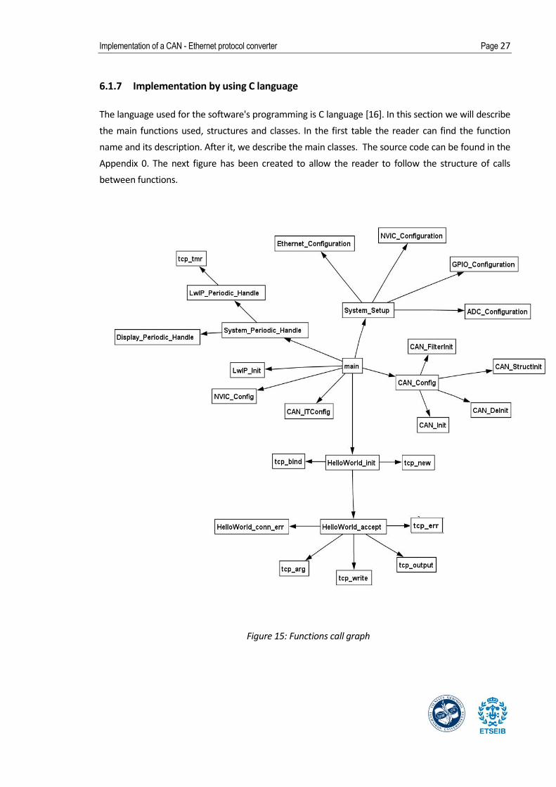
6.1.7 Implementation by using C language ............................................................................. 27
6.2 Hardware .................................................................................................................... 30
6.2.1 Glossary ........................................................................................................................... 30
6.2.2 Power Supply ................................................................................................................... 30
6.2.3 Network Connection ....................................................................................................... 30
6.2.4 Status Display .................................................................................................................. 31
6.2.5 Reset Method .................................................................................................................. 32
6.2.6 Schematic Design ............................................................................................................ 32
6.2.7 PCB design ....................................................................................................................... 32

Page 6 Report
7 TESTING ______________________________________________________ 33
7.1 Development of the test plan .................................................................................... 33
7.2 Test results .................................................................................................................. 34
8 CONCLUSIONS _________________________________________________ 36
9 LITERATURE ___________________________________________________ 37
9.1 References .................................................................................................................. 37
10 APPENDIX _____________________________________________________ 39
10.1 Schematic .................................................................................................................... 40
10.2 Bill of materials ........................................................................................................... 41
10.3 PCB I: Footprints and dimensions .............................................................................. 43
10.4 PCB II: 3D Model, bottom and top layers................................................................... 44
10.5 Source code I: main.c.................................................................................................. 45
10.6 Source code II: Net configuration (neconf.c) ............................................................. 51
10.7 Source code III: Interruptions ..................................................................................... 54
10.8 Source code IV: helloworld.c ...................................................................................... 59
10.9 Source code V: Board configuration (stm32f107.c) ................................................... 62

Implementation of a CAN - Ethernet protocol converter Page 7
2 List of figures
Figure 1: Wireless networking.____________________________________________________ 11
Figure 2: Connection of the gateway to control a device ________________________________ 12
Figure 3: Connection of different buses to a PC server _________________________________ 12
Figure 4: Example of gateway sold by esd [1] ________________________________________ 14
Figure 5: Example of gateway sold by SYS TEC electronic GmbH [2] _______________________ 14
Figure 6: OSI model Scheme [3] ___________________________________________________ 17
Figure 7: Data Encapsulation [4] __________________________________________________ 18
Figure 8: Table of frame format for CANbus _________________________________________ 19
Figure 9: Table of frame format for Ethernet transmissions _____________________________ 21
Figure 10: Gateway's implementation ______________________________________________ 23
Figure 11: Client – Server scheme [13] ______________________________________________ 23
Figure 12: Gateway structure _____________________________________________________ 24
Figure 13: Software Algorithm ____________________________________________________ 25
Figure 14: Software's states diagram _______________________________________________ 26
Figure 15: Functions call graph ___________________________________________________ 27
Figure 16: Front view of the CAN connector _________________________________________ 31
Figure 17: Front view of Ethernet RJ45 connector _____________________________________ 31
Figure 18: Hardware block diagram ________________________________________________ 32
Figure 19: Eval Boards and wires connections ________________________________________ 33
Figure 20: Image of the board in State 1 ____________________________________________ 34
Figure 21: Image of the board in State 2 ____________________________________________ 34

Page 8 Report
Figure 22: Image of the board in State 3 ____________________________________________ 35
Figure 23: Screen shot of the PC receiving the message sent. ___________________________ 35

Implementation of a CAN - Ethernet protocol converter Page 9
3 List of tables
Table 1: Gateway main features __________________________________________________ 13
Table 2: Comparative table of Gateways ____________________________________________ 15
Table 3: The seven layers of the OSI model __________________________________________ 18
Table 4: Description of the Principal Functions _______________________________________ 29
Table 5: CanRxMsg Class Table ___________________________________________________ 29
Table 6: Name Structure Table____________________________________________________ 30
Table 7: Table of connections ____________________________________________________ 31
Table 8: Table of RJ45 connections ________________________________________________ 31


Implementation of a CAN - Ethernet protocol converter Page 11
4 Introduction. Task analysis
4.1 The Purpose of the Project
The developed project has the main aim of achieving a new level of knowledge in the electronics
field. The subject chosen to fulfill this purpose has been CANbus to Ethernet protocol converters, also
called gateways. With this election we will be able to study two different protocols and the
implementation of a device capable of connecting two equipments whose protocols are not the
same.
In this report we will show the process of implementation of the mentioned protocol converter
including the explanation of the design of the software and the hardware together with the
appropriate tools which will be used for its implementation. Most of the tools employed - like C
language or Altium Designer – are new for us and learning to work well with them will also become a
goal during the project development.
Another point to achieve thanks to this project is to know how to write a software design description
(SDD) following the IEEE Standard for Information Technology-Systems Design-Software Design
Descriptions (IEEE 1016-2009).
Finally, learning the main features of the protocols is an important and basic objective given that the
correct design of the converter in based on the good acknowledgment of these.
4.2 The Applications of the Work
The protocol converter – or also known as gateway – features a CAN and an Ethernet ports. It
encapsulates CAN messages into TCP packets and sends them via Ethernet. Common applications
include:
1. Wireless networking of CAN networks
2. CAN-bus network diagnosis and test
3. Industrial control devices
Figure 1: Wireless networking.
Gateway

Page 12 Report
Given that the necessity of a device that could do these applications above is quite high, this kind of
gadget can already be found in the actual market. In section 6, we will analyze and compare two real
products.
4.3 Task analysis
CANbus-Ethernet gateways serves for interfacing networks through the Ethernet and to control the
networks via remote access. In this project we will only take into consideration the control task.
Gateways allow to connect one or various CANbus networks to a PC in order to read information. All
data between the CAN network and PC is transferred through an internal memory buffer inside the
Communicator.
Figure 2: Connection of the gateway to control a device
Figure 3: Connection of different buses to a PC server
Intranet PC Ethernet
CAN-Ethernet
Gateway
CAN-Ethernet
Gateway
CANbus 2
Ethernet
Ethernet
CANbus 1
Device A Device B ...
Device A Device B ...
Gateway
Data flow
Data flow

Implementation of a CAN - Ethernet protocol converter Page 13
The main features of the designed converter are sum up in the following Table 1. These
characteristics are based in the components that are chosen to assemble the converter which can be
seen in the Appendix 10.2, bill of materials.
CAN - Ethernet gateway
CPU:
Microcontroller: ARM Cortex-M3 core-based STM32F107VCT microcontroller
Interfaces:
Ethernet: IEEE-802.3-2002 compliant Ethernet connector
10Base-T/100Base-T (10/100 Mbit/s Ethernet)
IP address: 192.168.10.49
Subnet - Mask: 255.255.255.0
CAN interface: CAN 2.0A compliant connection
General:
Supply voltage: USB type B connection
Nom. min 4.5 VDC/max 11 VDC
Current 300 mA
Operating temp.: 0 - 40 ºC
Dimensions: 152 x 102 mm
Table 1: Gateway main features
Page 14 Report
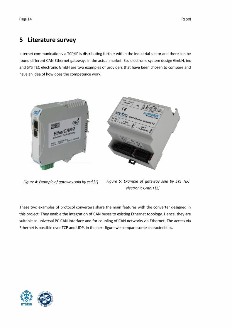
5 Literature survey
Internet communication via TCP/IP is distributing further within the industrial sector and there can be
found different CAN Ethernet gateways in the actual market. Esd electronic system design GmbH, inc
and SYS TEC electronic GmbH are two examples of providers that have been chosen to compare and
have an idea of how does the competence work.
Figure 4: Example of gateway sold by esd [1]
Figure 5: Example of gateway sold by SYS TEC
electronic GmbH [2]
These two examples of protocol converters share the main features with the converter designed in
this project. They enable the integration of CAN buses to existing Ethernet topology. Hence, they are
suitable as universal PC CAN interface and for coupling of CAN networks via Ethernet. The access via
Ethernet is possible over TCP and UDP. In the next figure we compare some characteristics.

Implementation of a CAN - Ethernet protocol converter Page 15
esd electronic system design GmbH [1] SYS TEC electronic GmbH [2]
CPU:
Microcontroller: ARM9, 200 MHz ARM9, high-performance
Interfaces:
Ethernet: 100BASE-TX
(100 Mbit/s Ethernet)
IEEE802.3
RJ45 Connector
10Base-T/100Base-T
(10/100 Mbit/s Ethernet)
IEEE802.3
RJ45 Connector
CAN interface: 5-pin open style 3.81 (CiA DR 303-1),
1 Mbit/s, ISO 11898-2, electrically
isolated
2x 5pin spring type connector with
optional Sub-D9 adapter cable, 10kbps to
1Mbps, ISO 11898 1/2, optical isolated
General:
Supply voltage: Nom. 24 VDC / 100 mA
Min./max.: 18 VDC / 32 VDC
Nom. 24 VDC / 100 mA
Min./max.: 10 VDC / 28,8 VCD
Operating temp.: 0 - 70 ºC 0 - 70 ºC
Dimensions
[mm]:
22 x 112 x 113 (L x W x H, in mm) 70 x 100 x 61 (L x W x H, in mm)
Price: 289,65 € 409,95 €
Table 2: Comparative table of Gateways

Page 16 Report
6 Implementation of the gateway
6.1 Software design
6.1.1 Glossary
IEEE Standards: Documents a developed within the IEEE Societies and the Standards Coordinating
Committees of the IEEE Standards Association (IEEE-SA) Standards Board.
Network: A computer network or data network is a telecommunications network that allows
computers to exchange data.
OSI: Open Systems Interconnection.
CAN: Controller Area Network.
Frame: Basic unit of data transfer at OSI Layer 2.
Packet: Basic unit of data transfer at OSI Layer 3.
Bus Topology: Network topology where computer devices are connected in a row to a continuous
length of cable segment. Each end of the cable segment must be terminated by means of a
terminating resistor.
Network Interface Card: NICs are printed circuit boards that are installed in computer workstations.
They provide the physical connection and circuitry required to access the network.
6.1.2 Introduction
In communication, protocols are the rules that define the format for exchanging messages between
two devices, allowing them to share and exchange data. A protocol must define the syntax,
semantics, and synchronization of communication. Two devices can use different protocols, making
it impossible to connect them directly. The solution to this situation is to use a protocol converter
which can solve both the hardware and software's incompatibility between devices.
In this section it is described the software design process along with a basic explanation of CANbus
and Ethernet protocols' main characteristics.
For a better comprehension of the protocols that the controller will work with we would like to
introduce the OSI model, which include both our protocols. OSI stands for Open Systems

Implementation of a CAN - Ethernet protocol converter Page 17
Interconnection, as a reference model for the network world. This model divides networking into 7
layers explained in Table 3.
Figure 6: OSI model Scheme [3]
The OSI model is not a networking standard but a framework into which the various networking
standards can fit. In other words, is a logical model for how network systems are supposed to
communicate with each other, so basically, all the model does is to break down the different
components of network communication and classify them into layers. The protocols of the OSI
model are used to organize the data into packets, with headers and trailers. This procedure is
called encapsulation. Basically, when a packet is born, the packet is wrapped ("encapsulated") in
a header by the first protocol (for example, the TFTP protocol), then the whole thing (TFTP
header included) is encapsulated again by the next protocol (e.g. TCP), then again by the next
(e.g. IP), then again by the final protocol on the physical layer (e.g. Ethernet).
When another computer receives the packet, the hardware strips the Ethernet header, the
kernel strips the IP and UDP headers, the TFTP program strips the TFTP header, and it finally has
the data [4].

Page 18 Report
Figure 7: Data Encapsulation [4]
In the following table it is described the 7 layers of the OSI model. As it can be seen, the
layers – from top to bottom – are for what it's closest to the user to what it's the
information out on the network.
Layer Layer Name Description Examples
1 Physical Governs the layout of cables and devices. Ethernet
2 Data Link
Provides MAC addresses to uniquely identify
network nodes and means for data to be sent over
the Physical layer in the form of packets.
PPP
3 Network Handles routing of data across network segments.
Creates logical paths to transmit data. IP
4 Transport Provides for reliable delivery of packets. TCP
5 Session Establishes sessions between network applications. NetBIOS
names
6 Presentation Converts data so that systems that use different
data formats can exchange information. ASCII, JPEG
7 Application Allows applications to request network services. It
interacts directly with the user. HTTP, Telnet
Real protocols may not follow exactly this structure and some layers may lack, which is the case of
our two protocols used. CANbus protocol defines layer 1 (physical) and 2 (Data link) and Ethernet – as
said – only covers the physical layer, however, Communication protocols for Ethernet networks
encompass both the data-link and physical layers. Converters can operate at all layers of the OSI
model since they:
Table 3: The seven layers of the OSI model
TCP
Implementation of a CAN - Ethernet protocol converter Page 19
1. Can provide a physical link between networks.
2. Create junctions between dissimilar networks.
3. Translate different network protocols and/ or applications.
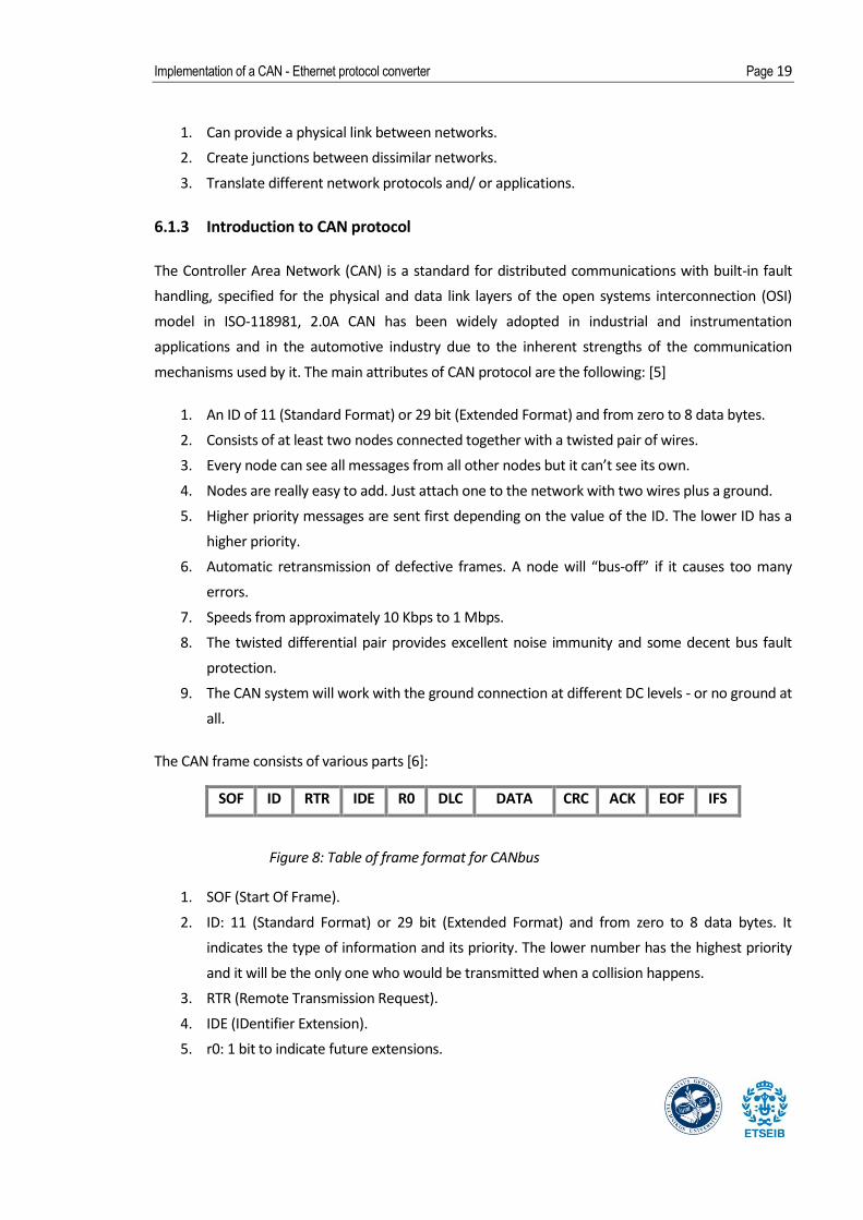
6.1.3 Introduction to CAN protocol
The Controller Area Network (CAN) is a standard for distributed communications with built-in fault
handling, specified for the physical and data link layers of the open systems interconnection (OSI)
model in ISO-118981, 2.0A CAN has been widely adopted in industrial and instrumentation
applications and in the automotive industry due to the inherent strengths of the communication
mechanisms used by it. The main attributes of CAN protocol are the following: [5]
1. An ID of 11 (Standard Format) or 29 bit (Extended Format) and from zero to 8 data bytes.
2. Consists of at least two nodes connected together with a twisted pair of wires.
3. Every node can see all messages from all other nodes but it can’t see its own.
4. Nodes are really easy to add. Just attach one to the network with two wires plus a ground.
5. Higher priority messages are sent first depending on the value of the ID. The lower ID has a
higher priority.
6. Automatic retransmission of defective frames. A node will “bus-off” if it causes too many
errors.
7. Speeds from approximately 10 Kbps to 1 Mbps.
8. The twisted differential pair provides excellent noise immunity and some decent bus fault
protection.
9. The CAN system will work with the ground connection at different DC levels - or no ground at
all.
The CAN frame consists of various parts [6]:
SOF ID RTR IDE R0 DLC DATA CRC ACK EOF IFS
1. SOF (Start Of Frame).
2. ID: 11 (Standard Format) or 29 bit (Extended Format) and from zero to 8 data bytes. It
indicates the type of information and its priority. The lower number has the highest priority
and it will be the only one who would be transmitted when a collision happens.
3. RTR (Remote Transmission Request).
4. IDE (IDentifier Extension).
5. r0: 1 bit to indicate future extensions.
Figure 8: Table of frame format for CANbus

Page 20 Report
6. DLC (Data Length Code): 4 bits define the number of bytes of the data (0-8).
7. DATA: Between 0 i 8 bytes of application data.
8. CRC (Cyclic Redundancy Check): 15 bits redundants which allow error detection.
9. ACK (Acknowledge): 2 bits.
10. EOF (End Of Frame): 7 bits.
11. IFS (InterFrame Space): 7 bits.
6.1.4 Introduction to Ethernet protocol (TCP/IPv4)
As we said at the beginning of this chapter, networking allows one computer to send information to
and receive information from another. We can classify network technologies as belonging to one of
two basic groups. Local area network (LAN) technologies connect many devices that are relatively
close to each other and Wide area network (WAN) technologies connect a smaller number of devices
that can be many kilometers apart. In comparison to WANs, LANs are faster and more reliable [7].
For the last few decades, Ethernet has been a relatively inexpensive, reasonably fast, and most
popular LAN technology all around the world. Ethernet technology uses a media access control
method called Carrier Sense Multiple Access/Collision Detection (CSMA/CD) to transmit data. The
IEEE 802.3 standard defines Ethernet protocols for OSI’s Media Access Control (MAC) sublayer and
physical layer network characteristics. Typically, uses coaxial cable or special grades of twisted pair
wires. Ethernet IEEE 802.2 standard defines protocols for the Logical Link Control (LLC) sublayer.
Ethernet's main features are passive performance, contention-based broadcast, baseband signaling
and CSMA/CD. Passive technology means that there is no one device controlling the network.
Contention-based means that every device must compete with every other device for access to the
shared network. Baseband signaling uses the entire bandwidth of a cable for a single transmission.
Only one signal can be transmitted at a time and every device on the shared network hears broadcast
transmissions. In other words, devices take turns. They can transmit only when no other device is
transmitting. To achieve a correct performance Ethernet use CSMA/CD [8].
CSMA/CD stands for Carrier-Sense Multiple Access / Collision Detection. Carrier-Sense means that
each computer on the network 'listens' and senses whether there is traffic on the cable before
sending. Multiple Access allows all computers to have access to the cable at any given time, they
have equal access to the network. All devices on the network receive the transmission and check the
framed packet’s destination address. If the destination address matches the device’s address, the
device accepts the data; if the address does not match, the device simply ignores the transmission.
Finally, if two computers send data at exactly the same time, the Collision Detection will detect that a
collision has occurred so they can re-send their data after a random period of time.

Implementation of a CAN - Ethernet protocol converter Page 21
In the IEEE 802.3 standard, the frame format defined is bellow.
Preamble SFD Destination
Address
Source
Address Length Data and Pad FCS
1. Preamble: 7 bytes.
2. SFD (Start Frame Delimiter): 1 byte.
3. Destination Address: 2 or 6 bytes.
4. Source Address: 2 or 6 bytes.
5. Length: 2 bytes.
6. Data: 46 - 1500 bytes. If the data field is less than the required 46 bytes, a pad field is added
to the data frame. The bytes added for padding purposes are usually zeros.
7. FCS (Frame Check Sequence): 4 bytes for error detection.
For layers 3 and 4, the IP (Internet Protocol) and TCP (Transmission Control Protocol) protocols will
be applied. IP will handle the routing of data and TCP will be in charge that this data arrive correctly
to its destination. It could be said that IP manage the where do the message go and TCP the how they
are transmitted there. When both protocols IP and TCP are used, it's called TCP/IP model and it's
well-spread in the industry [9].
It will be used the Internet Protocol Version 4, also called IPv4. It has addresses made up of four
bytes, and is commonly written in "dots and numbers" form, like: 192.168.0.1. Devices are
grouped in networks. The IP address is composed of two parts - the network portion of the IP
address and the host portion - the last one specifies the device from the network. The network
portion of the IP address is described by something called the netmask, which you bitwise-AND with
the IP address to get the network number out of it. The netmask usually looks something
like 255.255.255.0.
The TCP works transmitting the data progressively. First, one device sends one package (the packages
are small - bits or bytes) to the second device. If the package is received correctly, this latter sends it
back. Every time the first device receive the correct package, it will send the double number of
packages it has sent before and will wait that the second one sends the last package received. If this
package is not the correct one, the first device will go back to send just one package. This process is
called windowing and assures that all information transmitted will be received correctly [10].
Figure 9: Table of frame format for Ethernet transmissions

Page 22 Report
6.1.5 Development of the software architecture
For the design of the software we have used the evaluation board STM3210C-EVAL [11], a complete
development platform for STMicroelectronics' ARM Cortex-M3 core-based STM32F107VCT
microcontroller. The board includes Ethernet and CAN peripherals which makes it adequate for our
proposes. The application has been programmed in language C and edited and compiled by µVision4
from Keil.
In this section it will be described the Software Design Description (SDD) of the program that will
govern the converter. This description will follow some of the bases determined in the IEEE Std 1016-
2009 Standard for Information Technology [12].
The design stakeholders of CANbus-Ethernet gateway project are developers, testers and analysts.
Design concern of the stakeholders is understanding how the program runs. End product has to
contain design features that are described at SDD document.
The software design has been based in the following basic requirements in order to achieve the
correct functionality of the system.
a. The inputs will be in CAN protocol
b. The outputs have to be in TCP/IP protocol
c. Information to be shown through UI: message's ID, message's length and message.
There are three main viewpoints of our design which will be described in this section together with
UML diagrams that clarify its relations and meaning:
1. Context viewpoint: Shows the functionalities between user and system.
2. Implementation viewpoint: Implementation defines the components assembled together to
make a complete physical system.
3. Process viewpoint: Defines the flow of the system.
First we will explain the Context Viewpoint. The user will not take an important part in this system,
his only role is to connect the converter to the devices. The gateway will transmit all the data it
receive from the external device to the computer, where the user will be able to read it.
About the implementation viewpoint, the system will have four main components. These consist of
the CANbus connection, the embedded system, the Ethernet connection and the PC through which
we'll read the messages.
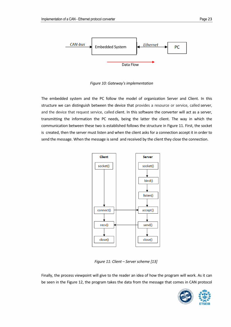
Implementation of a CAN - Ethernet protocol converter Page 23
Data Flow
The embedded system and the PC follow the model of organization Server and Client. In this
structure we can distinguish between the device that provides a resource or service, called server,
and the device that request service, called client. In this software the converter will act as a server,
transmitting the information the PC needs, being the latter the client. The way in which the
communication between these two is established follows the structure in Figure 11. First, the socket
is created, then the server must listen and when the client asks for a connection accept it in order to
send the message. When the message is send and received by the client they close the connection.
Figure 11: Client – Server scheme [13]
Finally, the process viewpoint will give to the reader an idea of how the program will work. As it can
be seen in the Figure 12, the program takes the data from the message that comes in CAN protocol
Figure 10: Gateway's implementation
Embedded System

Page 24 Report
format and extracts the data to pack it in a new data message in Ethernet protocol format to
prosecute with its transmission [14].
6.1.6 Development of software algorithm
The structure of the program is based in a main function that initialize the peripherals, set up the
variables properly and calls the function in charge of creating the connection with the PC – called
helloworld(). This function will create a new socket following the structure client -server mentioned
in the previous chapter 6.1.5. This connection will allow the converter to transfer the data received
from the CAN connection to the computer. The main function will create an infinite loop responsible
of sending all the data received instantly. The latter is a function based on the lwIP (light – weight
stack) [15][14]. lwIP is a small independent implementation of the TCP/IP protocol suite developed by
Adam Dunkels and focused on reducing resource usage while still having a full scale TCP to complete
the code. Simultaneously, another source code will be handling the interruptions. Using the
STM32F10x standard peripheral library we have created a function that responds to the CAN
incoming messages getting its data for later processing. This data will be classified and modified to
adapt it for the TCP/IP frame. In the simplest words possible, our program takes the frame that
comes in CAN protocol format and extracts the data to create a new frame in Ethernet protocol to
prosecute to its transmission. This algorithm is represented in the figure that follows.
Figure 12: Gateway structure

Implementation of a CAN - Ethernet protocol converter Page 25
Figure 13: Software Algorithm

Page 26 Report
The functions that appear in the previous diagram are described in the following section 4.2.7.
Meanwhile the system's program could be separated in two main functions, the states' diagram of
the system can be represented in one single draw, as can be seen in the Figure 14.
Figure 14: Software's states diagram
The state Error of connection will be indicated by lightning a LED. The other states have no interaction
with the user with the exception of the success with the Transmitting message to PC, which will be
visual by showing the message transmitted through the PC screen.
Reset button
pressed
Implementation of a CAN - Ethernet protocol converter Page 27
6.1.7 Implementation by using C language
The language used for the software's programming is C language [16]. In this section we will describe
the main functions used, structures and classes. In the first table the reader can find the function
name and its description. After it, we describe the main classes. The source code can be found in the
Appendix 0. The next figure has been created to allow the reader to follow the structure of calls
between functions.
Figure 15: Functions call graph

Page 28 Report
Function Description
CAN_Receive() Receives a message through CAN.
CAN_ITConfig() Enables or disables the specified CAN interrupts.
NVIC_Config() Configures the nested vectored interrupt controller.
LwIP_Init() Initializes the lwIP stack (IP address and memory).
CAN_Config() Configures the CAN.
CAN_Filterinit() Initializes the CAN peripheral according to the specified parameters in
the CAN_FilterInitStruct.
CAN_Structinit() Fills each CAN_InitStruct member with its default value.
CAN_DeInit() Deinitializes the CAN peripheral registers to their default reset values.
CAN_Init() Initializes the CAN peripheral according to the specified
parameters in the CAN_InitStruct.
System_Setup() Setup STM32 system (clocks, Ethernet, GPIO, NVIC) and STM3210C-
EVAL resources.
STM_EVAL_LEDOn() Turns on the indicated LED between the brackets.
STM_EVAL_LEDOff() Turns off the indicated LED between the brackets.
Ethernet_Configuration() Configures the Ethernet Interface.
GPIO_Configuration() Configures the different GPIO ports.
ADC_Configuration() Configures the analog-to-digital converter (ADC).
System_Periodic_Handle() Handles the periodic tasks of the system like LEDs status or LwIP
changes.
Display_Periodic_Handle() LEDs periodic handling.
LwIP_Periodic_Handle() TCP periodic process every 250 ms.
HelloWorld_init() Initialize the application.
tcp_bind() Assign to the new pcb a local IP address and a port number.
tcp_new() Create a new TCP control block.
HelloWorld_accept() This function is called when the Telnet connection is established
through the function tcp_accept().
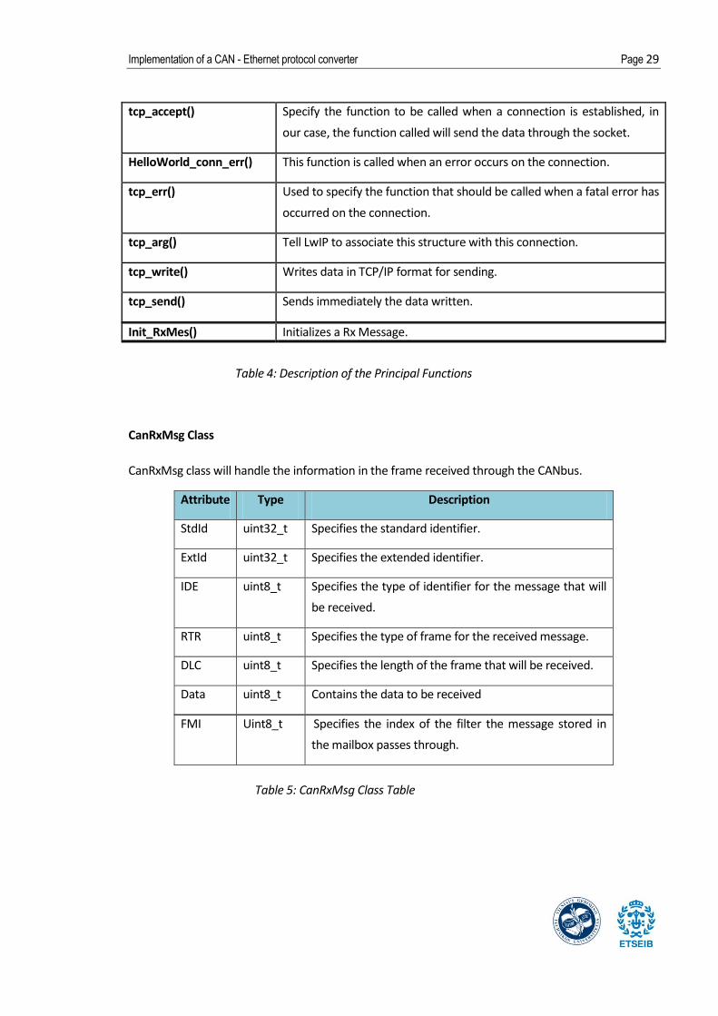
Implementation of a CAN - Ethernet protocol converter Page 29
tcp_accept() Specify the function to be called when a connection is established, in
our case, the function called will send the data through the socket.
HelloWorld_conn_err() This function is called when an error occurs on the connection.
tcp_err() Used to specify the function that should be called when a fatal error has
occurred on the connection.
tcp_arg() Tell LwIP to associate this structure with this connection.
tcp_write() Writes data in TCP/IP format for sending.
tcp_send() Sends immediately the data written.
Init_RxMes() Initializes a Rx Message.
CanRxMsg Class
CanRxMsg class will handle the information in the frame received through the CANbus.
Attribute Type Description
StdId uint32_t Specifies the standard identifier.
ExtId uint32_t Specifies the extended identifier.
IDE uint8_t Specifies the type of identifier for the message that will
be received.
RTR uint8_t Specifies the type of frame for the received message.
DLC uint8_t Specifies the length of the frame that will be received.
Data uint8_t Contains the data to be received
FMI Uint8_t Specifies the index of the filter the message stored in
the mailbox passes through.
Table 4: Description of the Principal Functions
Table 5: CanRxMsg Class Table

Page 30 Report
Name Structure
The name structure will be used to save the data from the message in CANbus format so it can be
added in its place in the Ethernet format frame.
Attribute Type Description
length int Length of the data.
bytes char Data.
6.2 Hardware
6.2.1 Glossary
JTAG: Joint Test Action Group. Common name used for the standard which is devised by electronic
engineers for testing and debugging printed circuit board.
CAN 2.0A: Referring to the standard format with an 11-bit identifier.
RJ45: Connector standardized as the IEC 60603-7 8P8C modular connector with eight conductors.
Cat 3 or Cat 5: Category of the wires.
6.2.2 Power Supply
For the operation of the device, a direct voltage of 5 V is needed. The power is supplied via a USB -
Device connection and controlled by a power regulator that lowers it to 3,3V.
The USB Device-Interface is connected to it via a USB-plug of Type B. The power regulator will have a
minimum/maximum input Voltage of 4.5/14 V, an output voltage of 3.3 V and a current of 300 mA.
6.2.3 Network Connection
CANbus Connection
The gateway supports CAN 2.0A compliant CANbus communication based on 3.3 V CAN transceiver.
The connection will be through CAN D-type 9-pin male connector.
Table 6: Name Structure Table

Implementation of a CAN - Ethernet protocol converter Page 31
Figure 16: Front view of the CAN
connector
Pin number Description Pin number Description
1, 4, 8, 9 NC 7 CANH
2 CANL 3, 5, 6 GND
Table 7: Table of connections
Ethernet Connection
The Ethernet (10Base-T/100Base-TX) is connected by means of a usual CAT 3 or CAT 5 network cable
with a RJ45-plug.
Figure 17: Front view of
Ethernet RJ45
connector
Pin number Description Pin number Description
1 TxData + 5 Shield
2 TxData - 6 RxData -
3 RxData + 7 Shield
4 Shield 8 Shield
Table 8: Table of RJ45 connections
JTAG
The CAN-Ethernet gateway features a JTAG receptacle which is connected to it via a 20 pins header
as indicated by the IEEE 1149.1 Standard Test Access Port and Boundary-Scan Architecture. This
interface allows for configuration of the CAN-Ethernet Gateways V2. This connection is especially
made for initial configuration.
6.2.4 Status Display
For the display of the operation status of the gateway, 2 LEDs are needed. One will be used to
indicate if the power supply is running in correct conditions, the second one will indicate if the

Page 32 Report
Ethernet connection is accepted by the pc. Both of the LEDs will be on if the connection they are
signaling is established correctly.
6.2.5 Reset Method
The only interface user - device is through a reset button. The converter starts running when its
connected to the power supply, if the Ethernet LED is not on but the power supply is correct, the
reset button should be pressed to restart the connection.
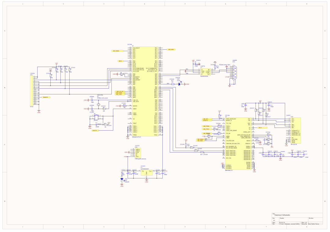
6.2.6 Schematic Design
In the following figure its shown how the functions explained in the previous sections are
interconnected. It is a visual and clear way to understand the relations between blocks before
designing the schematic design, which can be found in the Appendix 10.1.
Figure 18: Hardware block diagram
The reader can also find the bill of materials after schematic design, with the physical components
that should be used to assemble the embedded system, its price and supplier.
6.2.7 PCB design
At the end of this project we will not have the physical board for economic and time reasons.
However, a PCB design has been proposed with the specific components that should be build in the
embedded system. The PCB design is attached in the appendices 10.3 and 10.4.

Implementation of a CAN - Ethernet protocol converter Page 33
7 Testing
7.1 Development of the test plan
The testing has been developed for the software part of the converter but not for the hardware. This
is given that the hardware has not been implemented physically for economic and time reasons. For
the testing, it has been used two STM3210C_EVAL boards, one CAN wire, one Ethernet wire and a
computer.
One of the boards has been programmed to work as the gateway. We have used the program
developed during the project but with one variation: one function will switch on a LED when a
message through CAN will be received and will switch off this same LED when the message will be
send through Ethernet connection. This LED will allow us to search for some possible errors or
malfunctions of the software. As in the original software, other 2 lights will be used, one for the
power supply (it will be the screen or a LED included in the board for this same use) and another for
the Ethernet connection.
The other board has been programmed with a software that will make it work as a transmitter. It will
send a message through CAN every time the button reset is pressed. This message will be in standard
CAN protocol.
The gateway board was connected to a computer through an Ethernet wire. The TCP messages that
the board send to it will be controlled with telnet [17]. In the following figure it is shown the two
boards and the connections established.
Figure 19: Eval Boards and wires connections

Page 34 Report
7.2 Test results
After realizing the hardware connections needed, we will establish connection of the PC and the
board which is working as a converter. After this step, all the attempts that have been carried on (>10
attempts) would end up in the following state:
State 1
- When the connection is accepted by the
client (computer), the light in the green
LED turns on.
- If no message enters to the converter,
the green LED keeps on and no changes
can be seen.
- If the connection fails, the green light
will turn off after a few second (it can
last even a minute).
Figure 20: Image of the board in State 1
When State 1 has been checked, we proceed to transmit one message from one board to the other.
This is done pressing the reset button on the transmitter board and it will reach State 2.
State 2
- When a message is received and the
connection is on the red and green LEDs
will be switch on, like in the picture next
to this lines.
- When the message will be send to the
PC, the red LED will turn off returning to
state 1.
- This state should last a short time given
that the receiving and sending of the
message should be instantaneous.
Figure 21: Image of the board in State 2
Implementation of a CAN - Ethernet protocol converter Page 35
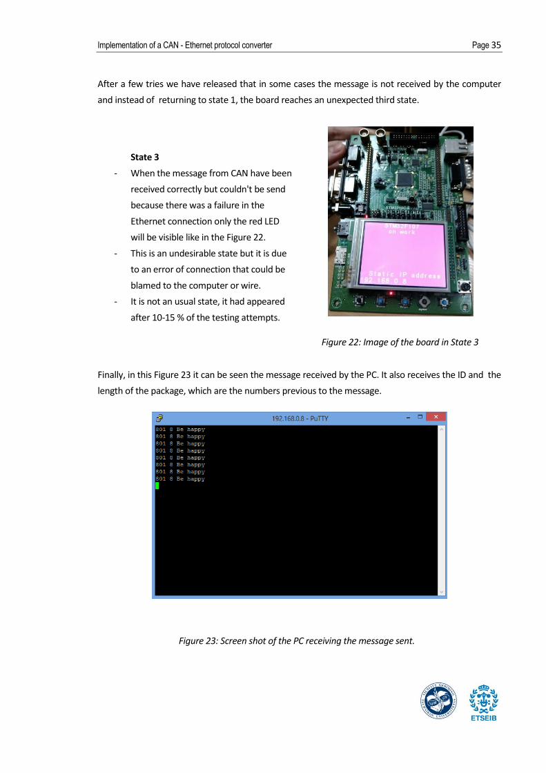
After a few tries we have released that in some cases the message is not received by the computer
and instead of returning to state 1, the board reaches an unexpected third state.
State 3
- When the message from CAN have been
received correctly but couldn't be send
because there was a failure in the
Ethernet connection only the red LED
will be visible like in the Figure 22.
- This is an undesirable state but it is due
to an error of connection that could be
blamed to the computer or wire.
- It is not an usual state, it had appeared
after 10-15 % of the testing attempts.
Figure 22: Image of the board in State 3
Finally, in this Figure 23 it can be seen the message received by the PC. It also receives the ID and the
length of the package, which are the numbers previous to the message.
Figure 23: Screen shot of the PC receiving the message sent.

Page 36 Report
8 Conclusions
In this section it will be discussed both the results of the testing - described in section 6 - and the
outlook of the finished project. In the following lines, the reader should be able to understand the
conclusions that can be extract from the work done.
First we will analyze the testing of the software. The converter was designed to receive and send
messages instantly between two devices that used different protocols – CANbus protocol and
Ethernet. The result is satisfactory and it works correctly when the connection is good. The messages
received through CANbus format are converted correctly into TCP packages and send to the
computer. If the connection is down, the last message received is saved unless another one is
received, in that case the new replace it. This action of saving the last income message was not a
requirement but it is not an undesirable problem. In general we can say that the performance was
the required but the source code could be cleaned of useless parts. This would improve the speed in
which the device detects the error of Ethernet connection. There might be more code than the
necessary because we have joined and modified different libraries and example codes from different
sources. The speed of data transfer receiving by the CAN connection is up to 1 Mbits/s and the speed
of data send can be up to 100 Mbits/s. It is left for future studies what would happen if the data
transfer rate income would be higher than the sending speed. It should be checked if the connection
would drop or the message would be send incomplete or with errors.
The hardware designed has not been physically created mainly because of the price. The 60
components needed sum 93,65 €. These need to be weld into a 152 x 102 mm board and the price of
it would be 61 € (46,00 € for the board and 15 € for the manufacture). This increase the total price of
the board to 154,65 €. In our case, all the amount of money is for the hardware. The software has
been created by us and don't contribute to the final price.
On another hand, the project have not been entirely successful – not creating the physical model
being the main reason of this reckon. The software has been created and executed but the hardware
has only been designed. However, the knowledge gained with the designing should be appreciated.
We have been working in an unknown field with new tools and succeed to develop a correct project.
How to create schematics and PCB designs with Altium designer has been a challenge such as
learning programming in language C, with which we have written 60 lines of the code. The effort and
work put in this project have brought it to what it is and the result has been satisfactory specially for
what it has contributed to our knowledge.

Implementation of a CAN - Ethernet protocol converter Page 37
9 Literature
9.1 References
[1] esd Electronics, USA, EtherCAN/2
[http://www.esd-electronics-usa.com/CAN-CANopen-ETHERNET-Gateway-ARM9-
microcontroller-CANbus-diagnostics-SNMP-support-EtherCAN/2.html, 24/10/2014]
[2] SYSTEC Electronic, CAN-Ethernet Gateway V2.
[http://www.systec-electronic.com/en/products/industrial-communication/interfaces-and-
gateways/can-ethernet-gateway-v2, 24/10/2014]
[3] OSI model image.
[http://www.anybus.com/technologies/gateways.shtml, 29/09/2014]
[4] Beej's Guide to Network Programming: Using Internet Sockets (Version 3.0.15) by Brian "Beej
Jorgensen" Hall.
[http://beej.us/guide/bgnet/output/html/multipage/theory.html, 12/09/2014]
[5] CAN Primer: Creating Your Own Network by Bob Boys.
[http://www.keil.com/download/files/canprimer_v2.pdf, 15th October 2014]
[6] Slides from 'Introducció a l'electrònica' by Emili Lupon, UPC, translated by Berta Trullàs.
[7] Practical Networking With Ethernet. Spurgeon, Charles E. (1997).
[8] Basic vocabulary from Ethernet by The engineer 360.
[http://theengineer360.info/instrumentation17.php, 15/01/2015]
[9] International Thomson Computer Press, Boston, Massachusetts.
[10] Notes from 'Protocols de transmissió de dades' translated by Berta Trullas, ETSETB (UPC)
[11] Manual of STM3210C_EVAL boards.
[http://www.st.com/st-web-ui/static/active/en/resource/technical/document/
user_manual/CD00212441.pdf, 14/11/2014]
[12] IEEE Standard for Information Technology—Systems Design—Software Design Descriptions.
[https://cow.ceng.metu.edu.tr/Courses/download_courseFile.php?id=3870, 17/11/2014]
[13] TINKLINIS PROGRAMAVIMAS by Dr. Andrius Ušinskas and Dr. Arūnas Šaltis, 2010.

Page 38 Report
[14] Unix Network Programming, Volume 1: The Sockets Networking API (3rd Edition) by W.
Richard Stevens, Bill Fenner and Andrew M. Rudoff. Nov 24, 2013.
[15] lwIP TCP/IP stack demonstration for STM32F107xx connectivity line microcontrollers.
[http://www.st.com/st-web-ui/static/active/en/resource/technical/document/
application_note/CD00255062.pdf, 17/09/2014]
[16] Programming in C (3rd Edition) by Stephen G. Kochan. Jul 18, 2004.
[17] Beginning Linux Programming (3rd edition) by Neil Matthew and Richard Stones. Nov 5,
2004.

Implementation of a CAN - Ethernet protocol converter Page 39
10 Appendix
1
1
2
2
3
3
4
4
5
5
6
6
7
7
8
8
D D
C C
B B
A A
Title
Number RevisionSize
A2
Date: 2015.01.20 Sheet ofFile: C:\Users\..\Schematic_converter.SchDoc Drawn By:
BOOT094
NC73
NRST14
OSC_IN12
OSC_OUT13
PA0-WKUP23
PA124
PA225
PA326
PA429
PA530
PA631
PA732
PA867
PA968
PA1069
PA1170
PA1271
PA13/JTMS/SWDIO72
PA14/JTCK/SWCLK76
PA15/JTDI77
PB035
PB136
PB2/BOOT137
PB3/JTDO89
PB4/JNTRST90
PB591
PB692
PB793
PB895
PB996
PB1047
PB1148
PB1251
PB1352
PB1453
PB1554
PC0 15
PC1 16
PC2 17
PC3 18
PC4 33
PC5 34
PC6 63
PC7 64
PC8 65
PC9 66
PC10 78
PC11 79
PC12 80
PC13-TAMPER-RTC 7
PC14-OSC32_IN 8
PC15-OSC32_OUT 9
PD0 81
PD1 82
PD2 83
PD3 84
PD4 85
PD5 86
PD6 87
PD7 88
PD8 55
PD9 56
PD10 57
PD11 58
PD12 59
PD13 60
PD14 61
PD15 62
PE0 97
PE1 98
PE2 1
PE3 2
PE4 3
PE5 4
PE6 5
PE7 38
PE8 39
PE9 40
PE10 41
PE11 42
PE12 43
PE13 44
PE14 45
PE15 46
VDD_150
VDD_275
VDD_3100
VDD_428
VDD_511
VDDA22
VREF-20
VREF+21
VSS_1 49
VSS_2 74
VSS_3 99
VSS_4 27
VSS_5 10
VSSA 19
VBAT6
2432098U1
STM32F107VCT
MII_TX_ENMII_TXD0MII_TXD1
MII_MDCMII_MDIO
MCO
2449397RLX125MHz (with socket)
220
2351615R6 10K
2131811R10
1
4 3
2
1712997B1
RESET
+3V31709233
C3
100nF
RESET#
10k2131811
R7
GND
GND
GND
GND
GND
GND10K
2131811R8
RESET#
10K
2131811
R3
10K
2131811R5
10K
2131811R1
10K
2131811R2
10K
2131811
R4GND
1234567891011121314151617181920
1392410CN1
JTAG
GND
+3V3
+3V3
1 2
2426228LD2Green
PD7 GND
330
2351694R11
D1
GND2
VCC3
R4 Vref 5CANL 6CANH 7RS 8
16487521103105
U3
SN65HVD230 +3V3
+3V3 1709233C8
100nFDefault setting: Open
162738495
1849899CN3
PD1
PD0
10K
2131811R18
Vin3
GN
D1
Vout 2
2112622U2LD1086D2M33
2408404
C4220uF
1816843
C610uF
1709233
C7100nF
+5V
12 2426229
LD1red
2408404
C5220uF1K5
1799521
R9
GND
GND
VCC1 D-2 D+3 GND4 SHELL0 SHELL0
1321918CN2
USB-typeB connector
GND
MDC31 MDIO30
TX_CLK1
TX_EN2
TXD_03
TXD_14
TXD_25
TXD_3/SNI_MODE6
RX_CLK38
RX_DV/MII_MODE39 RX_ER/MDIX_EN41
RXD_0/PHYAD143
RXD_1/PHYAD244
RXD_2/PHYAD345
RXD_3/PHYAD446
CRS/CRS_DV/LED_CFG40
COL/PHYAD042
X1 34
X2 33
25MHz_OUT 25
LED_LINK/AN0 28LED_SPEED/AN1 27LED_ACT/COL/AN_EN 26
RESET_N29 PWR_DOWN/INT7
TD- 16TD+ 17
RD- 13RD+ 14
RBIAS 24
PFBOUT 23
PFBIN1 18
PFBIN2 37
RESERVED 8
RESERVED 9
RESERVED 10RESERVED 11
RESERVED 12
RESERVED 20RESERVED 21
IOVDD3332
IOVDD3348
IOGND 35
IOGND 47
DGND 36
AVDD3322 AGND 15
AGND 19
U4
DP83848CVV
MII_TXD0
MII_TXD1
MII_TX_EN
+3V3
2K22351566 R12
MII_MDIOMII_MDC
RESET#
PA2PC1
MII_INT
+3V3
2K2
2351566R21
MCO
+3V3
GND
4.87K
2351724R22
GND
100nF
1709233C10
100nF
1709233
C12100nF
1709233
C13
100nF
1709233C15
100nF
1709233
C16
100nF
1709233
C1710uF
1816843
C14
+3v3
GND
TD+1
TCT4
RD+3
RCT5
RD-6
LED(green)_A9
LED(green)_K10
LED(Yellow)_A11
LED(Yellow)_K12
NC7
CHS GND8
TD-2
Shield13
Shield14
1345055CN4
J0011D21B
+3V3GND
100nF
1709233
C11100nF
1709233C9
GND
+3V3
GND
1K5
1799521R16
+3V3332351691R20
33 2351691R17
332351691
R19
332351691
R13
332351691
R14
332351691R15
50
2142117R23
502142117
R2450
2142117R25
502142117
R26
2k2
2351566R27
2k22351566R28
2k22351566R29
20pF
1650896C1
20pF
1650896C2
Gateway's Schematic
1Berta Trullas Clavera
1
PIB101 PIB102
PIB103PIB104
COB1
PIC101 PIC102
COC1
PIC201 PIC202
COC2
PIC301 PIC302
COC3
PIC401
PIC402COC4
PIC501
PIC502COC5
PIC601
PIC602COC6
PIC701
PIC702COC7
PIC801PIC802
COC8
PIC901
PIC902COC9
PIC1001
PIC1002COC10
PIC1101
PIC1102COC11
PIC1201
PIC1202COC12
PIC1301
PIC1302COC13
PIC1401
PIC1402COC14
PIC1501
PIC1502COC15
PIC1601
PIC1602COC16
PIC1701
PIC1702COC17
PICN101
PICN102
PICN103
PICN104
PICN105PICN106
PICN107
PICN108
PICN109
PICN1010
PICN1011
PICN1012PICN1013
PICN1014
PICN1015
PICN1016
PICN1017PICN1018
PICN1019PICN1020
COCN1
PICN200
PICN201
PICN202PICN203
PICN204
COCN2
PICN300
PICN301
PICN302
PICN303
PICN304
PICN305
PICN306
PICN307
PICN308
PICN309
COCN3
PICN401
PICN402
PICN403
PICN404
PICN405
PICN406
PICN407PICN408
PICN409
PICN4010
PICN4011
PICN4012
PICN4013
PICN4014
COCN4
PILD101PILD102
COLD1
PILD201 PILD202
COLD2PIR101
PIR102COR1
PIR201
PIR202COR2
PIR301
PIR302COR3
PIR401
PIR402COR4
PIR501
PIR502COR5
PIR601 PIR602
COR6
PIR701PIR702COR7
PIR801PIR802COR8
PIR901
PIR902COR9
PIR1001PIR1002
COR10
PIR1101 PIR1102
COR11
PIR1201
PIR1202COR12
PIR1301 PIR1302
COR13
PIR1401 PIR1402
COR14
PIR1501 PIR1502
COR15
PIR1601PIR1602COR16
PIR1701 PIR1702COR17
PIR1801
PIR1802COR18
PIR1901 PIR1902
COR19
PIR2001 PIR2002
COR20
PIR2101
PIR2102COR21
PIR2201 PIR2202
COR22
PIR2301
PIR2302COR23
PIR2401
PIR2402COR24 PIR2501
PIR2502COR25
PIR2601
PIR2602COR26
PIR2701 PIR2702COR27
PIR2801 PIR2802COR28
PIR2901 PIR2902
COR29
PIU101PIU102
PIU103
PIU104
PIU105
PIU106
PIU107
PIU108
PIU109
PIU1010PIU1011
PIU1012PIU1013
PIU1014
PIU1015PIU1016
PIU1017
PIU1018
PIU1019
PIU1020
PIU1021
PIU1022
PIU1023PIU1024
PIU1025
PIU1026
PIU1027PIU1028
PIU1029
PIU1030
PIU1031
PIU1032
PIU1033
PIU1034
PIU1035
PIU1036PIU1037
PIU1038
PIU1039
PIU1040
PIU1041
PIU1042
PIU1043
PIU1044PIU1045
PIU1046
PIU1047
PIU1048
PIU1049PIU1050
PIU1051PIU1052
PIU1053
PIU1054
PIU1055
PIU1056
PIU1057
PIU1058
PIU1059PIU1060
PIU1061
PIU1062
PIU1063
PIU1064
PIU1065
PIU1066
PIU1067
PIU1068
PIU1069
PIU1070PIU1071
PIU1072
PIU1073
PIU1074PIU1075
PIU1076
PIU1077
PIU1078
PIU1079PIU1080
PIU1081
PIU1082PIU1083
PIU1084
PIU1085
PIU1086
PIU1087PIU1088
PIU1089
PIU1090
PIU1091
PIU1092PIU1093
PIU1094
PIU1095
PIU1096
PIU1097PIU1098
PIU1099PIU10100
COU1
PIU201
PIU202PIU203
COU2
PIU301
PIU302
PIU303
PIU304 PIU305
PIU306
PIU307
PIU308
COU3
PIU401
PIU402
PIU403
PIU404PIU405
PIU406
PIU407
PIU408
PIU409
PIU4010PIU4011
PIU4012
PIU4013
PIU4014
PIU4015
PIU4016PIU4017
PIU4018
PIU4019
PIU4020
PIU4021
PIU4022
PIU4023
PIU4024
PIU4025
PIU4026
PIU4027
PIU4028
PIU4029
PIU4030
PIU4031
PIU4032
PIU4033
PIU4034
PIU4035
PIU4036
PIU4037
PIU4038
PIU4039
PIU4040
PIU4041
PIU4042
PIU4043
PIU4044
PIU4045
PIU4046
PIU4047
PIU4048
COU4
PIX101
PIX102
COX1
PIC601 PIC701
PIC802
PIC901 PIC1102
PIC1502 PIC1602 PIC1702
PICN101
PICN102
PICN309
PICN404
PICN405
PIR202 PIR302 PIR402 PIR502
PIR701
PIR1202
PIR1602
PIR2102
PIR2302
PIR2402
PIR2502
PIR2602
PIR2702
PIR2802
PIR2902
PIU1010
PIU1019
PIU1027
PIU1049
PIU1074PIU1099
PIU202
PIU303
PIU4022
PIU4032
PIU4048
PIC401 PIC501
PICN201
PIR902 PIU203
PIB101
PIB104
PIC101
PIC201
PIC301
PIC402 PIC502 PIC602 PIC702
PIC801
PIC902
PIC1001
PIC1101
PIC1201 PIC1301 PIC1402 PIC1501 PIC1601 PIC1701
PICN104
PICN106
PICN108
PICN1010
PICN1012
PICN1014
PICN1016
PICN1018
PICN1020
PICN204
PICN300
PICN303
PICN305
PICN306
PICN408
PICN4013
PICN4014
PILD102
PILD202
PIR102 PIR802
PIR1002
PIR1802
PIR2202
PIU1011
PIU1022
PIU1028
PIU1050
PIU1075PIU10100
PIU201
PIU302
PIU4015
PIU4019
PIU4035
PIU4036
PIU4047
PIC102 PIR601PIX101
PIC202 PIU1012
PIX102
PIC1002 PIC1202 PIC1302 PIC1401
PIU4018
PIU4023
PIU4037
PICN103
PIR201
PIU1090
PICN105
PIR301 PIU1077
PICN107
PIR101
PIU1072
PICN109
PIR401PIU1076
PICN1011
PICN1013
PIR501
PIU1089
PICN1017
PICN1019
PICN200
PICN200
PICN202PICN203
PICN301
PICN302
PIU306
PICN304
PICN307PIU307
PICN308
PICN401
PIR2301
PIU4017
PICN402
PIR2401
PIU4016
PICN403
PIR2501
PIU4014
PICN406
PIR2601
PIU4013
PICN407
PICN409
PICN4010
PICN4011
PICN4012
PILD101
PILD201PIR1102
PIR602
PIU1013
PIR801
PIU1037
PIR901
PIR1001PIU1094
PIR1101PIU1088
PIR1201PIR1301
PIU1055
PIR1302 PIU4039
PIR1401
PIU1056
PIR1402 PIU4043
PIR1501
PIU1057
PIR1502 PIU4044
PIR1701
PIU1052
POMII0TXD1 PIR1702
PIU404
PIR1801PIU308
PIR1901
PIU1051
POMII0TXD0 PIR1902PIU403
PIR2001
PIU1048
POMII0TX0EN PIR2002PIU402
PIR2101 PIU407POMII0INT
PIR2201PIU4024
PIR2701PIU4026
PIR2801
PIU4027
PIR2901
PIU4028
PIU101PIU102
PIU103
PIU104
PIU105
PIU106
PIU107
PIU108
PIU109
PIU1015
PIU1017
PIU1018
PIU1020
PIU1021
PIU1023PIU1024
PIU1026
PIU1029
PIU1030
PIU1031
PIU1032
PIU1033
PIU1034
PIU1035
PIU1036
PIU1038
PIU1039
PIU1040
PIU1041
PIU1042
PIU1043
PIU1044PIU1045
PIU1046
PIU1047
PIU1053
PIU1054
PIU1058
PIU1059PIU1060
PIU1061
PIU1062
PIU1063
PIU1064
PIU1065
PIU1066PIU1068
PIU1069
PIU1070PIU1071
PIU1073
PIU1078
PIU1079PIU1080
PIU1081 PIU304
PIU1082
PIU301
PIU1083
PIU1084
PIU1085
PIU1086
PIU1087PIU1091
PIU1092PIU1093
PIU1095
PIU1096
PIU1097PIU1098
PIU305
PIU401
PIU405
PIU406
PIU408
PIU409
PIU4010PIU4011
PIU4012
PIU4020
PIU4021
PIU4025
PIB102
PIB103
PIC302
PICN1015
PIR702
PIU1014
PIU4029PORESET#
PIU4033
PIU1067
PIU4034 POMCO
PIU4038
PIU4040
PIU4041
PIU4042
PIU4045
PIU4046
PIR1601
PIU1025
PIU4030
NLPA2POMII0MDIO
PIU1016
PIU4031
NLPC1POMII0MDC
POMCO
POMII0INT
POMII0MDCPOMII0MDIO
POMII0TX0ENPOMII0TXD0POMII0TXD1
PORESET#
Implementation of a CAN - Ethernet protocol converter Page 41
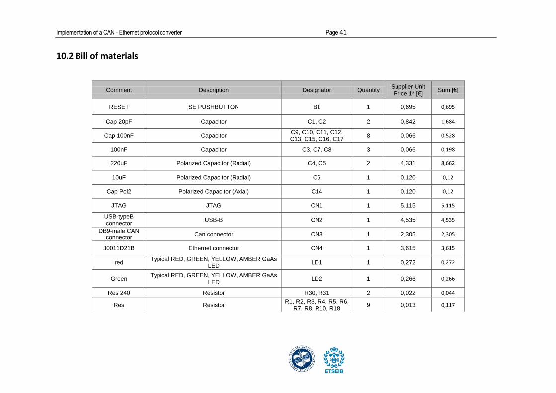
10.2 Bill of materials
Comment Description Designator Quantity Supplier Unit Price 1* [€]
Sum [€]
RESET SE PUSHBUTTON B1 1 0,695 0,695
Cap 20pF Capacitor C1, C2 2 0,842 1,684
Cap 100nF Capacitor C9, C10, C11, C12, C13, C15, C16, C17
8 0,066 0,528
100nF Capacitor C3, C7, C8 3 0,066 0,198
220uF Polarized Capacitor (Radial) C4, C5 2 4,331 8,662
10uF Polarized Capacitor (Radial) C6 1 0,120 0,12
Cap Pol2 Polarized Capacitor (Axial) C14 1 0,120 0,12
JTAG JTAG CN1 1 5,115 5,115
USB-typeB connector
USB-B CN2 1 4,535 4,535
DB9-male CAN connector
Can connector CN3 1 2,305 2,305
J0011D21B Ethernet connector CN4 1 3,615 3,615
red Typical RED, GREEN, YELLOW, AMBER GaAs
LED LD1 1 0,272 0,272
Green Typical RED, GREEN, YELLOW, AMBER GaAs
LED LD2 1 0,266 0,266
Res 240 Resistor R30, R31 2 0,022 0,044
Res Resistor R1, R2, R3, R4, R5, R6,
R7, R8, R10, R18 9 0,013 0,117

Page 42 Report
*Prices are taken from Farnell: Farnell element14 is a global high-service distributor of technology products, services and solutions for electronic system
design, maintenance and repair.
[www.farnell.com, 20/01/2015]
Res Resistor R6 1 0,013 0,013
Res Resistor R9, R16 2 0,013 0,026
Res Resistor R11 1 0,013 0,013
Res Resistor R12, R21, R27, R28,
R29 5 0,013 0,065
Res Resistor R13, R14, R15, R16,
R17, R19, R20 6 0,013 0,078
Res Resistor R22 1 0,013 0,013
Res 50 Resistor R23, R24, R25, R26 4 0,213 0,852
STM32F107VCT STM32 ARM-based 32-bit MCU with 64 Kbytes Flash, 100-pin LQFP, Industrial Temperature
U1 1 25,510 25,51
LD1086D2M33 Voltage regulator 3.3V U2 1 4,535 4,535
SN65HVD230 3.3V CAN transceiver U3 1 13,862 13,862
DP83848CVV PHYTER® Commercial Temperature Single Port
10/100 Mb/s Ethernet Physical Layer Transceiver, 48-pin LQFP
U4 1 19,399 19,399
25MHz (with socket)
Crystal X1 1 1,001 1,001
TOTAL: 60
93,643

Implementation of a CAN - Ethernet protocol converter Page 43
10.3 PCB I: Footprints and dimensions
Page 44 Report
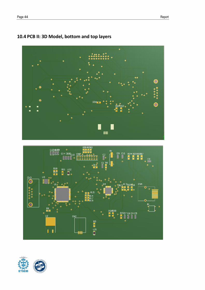
10.4 PCB II: 3D Model, bottom and top layers

Implementation of a CAN - Ethernet protocol converter Page 45
10.5 Source code I: main.c
******************************************************************************
00000003 * @file main.c
00000004 * @author MCD Application Team
00000005 * @version V1.0.0
00000006 * @date 11/20/2009
00000007 * @brief Main program body
00000008
******************************************************************************
00000009 * @copy
00000010 *
00000011 * THE PRESENT FIRMWARE WHICH IS FOR GUIDANCE ONLY AIMS AT PROVIDING
CUSTOMERS
00000012 * WITH CODING INFORMATION REGARDING THEIR PRODUCTS IN ORDER FOR THEM TO
SAVE
00000013 * TIME. AS A RESULT, STMICROELECTRONICS SHALL NOT BE HELD LIABLE FOR ANY
00000014 * DIRECT, INDIRECT OR CONSEQUENTIAL DAMAGES WITH RESPECT TO ANY CLAIMS
ARISING
00000015 * FROM THE CONTENT OF SUCH FIRMWARE AND/OR THE USE MADE BY CUSTOMERS OF
THE
00000016 * CODING INFORMATION CONTAINED HEREIN IN CONNECTION WITH THEIR PRODUCTS.
00000017 *
00000018 * <h2><center>© COPYRIGHT 2009 STMicroelectronics</center></h2>
00000019 */
00000020
00000021 /* Includes --------------------------------------------------------------
----*/
00000022 #include "stm32_eth.h"
00000023 #include "netconf.h"
00000024 #include "main.h"
00000025 #include "helloworld.h"
00000026 #include "stm32f10x.h"
00000027 #include "platform_config.h"
00000028 #include <stdio.h>
00000029 #include "stm3210c_eval_lcd.h"
00000030 #include "stm32f10x_can.h"
00000031
00000032
00000033 /* Private typedef -------------------------------------------------------
----*/
00000034 /* Private define --------------------------------------------------------
----*/
00000035 #define SYSTEMTICK_PERIOD_MS 10
00000036 #define CANx CAN1
00000037 #define GPIO_CAN GPIO_CAN1
00000038 #define GPIO_Remapping_CAN GPIO_Remapping_CAN1
00000039 #define GPIO_CAN GPIO_CAN1
00000040 #define GPIO_Pin_CAN_RX GPIO_Pin_CAN1_RX
00000041 #define GPIO_Pin_CAN_TX GPIO_Pin_CAN1_TX
00000042
00000043
00000044 #define KEY_PRESSED 0x01
00000045 #define KEY_NOT_PRESSED 0x00
00000046
00000047 /* Private macro ---------------------------------------------------------
----*/
00000048 /* Private variables -----------------------------------------------------
----*/
00000049 __IO uint32_t LocalTime = 0; /* this variable is used to create a time
reference incremented by 10ms */
00000050 uint32_t timingdelay;
00000051 CAN_InitTypeDef CAN_InitStructure;
00000052 CAN_FilterInitTypeDef CAN_FilterInitStructure;

Page 46 Report
00000053 CanTxMsg TxMessage;
00000054 extern CanRxMsg RxMessage;
00000055 char missatge[] = "HELLO";
00000056 char *str;
00000057 unsigned int val;
00000058 int MAX = 5;
00000059 int i;
00000060
00000061 /* Private function prototypes -------------------------------------------
----*/
00000062 void System_Periodic_Handle(void);
00000063 void NVIC_Config(void);
00000064 void CAN_Config(void);
00000065 extern void LCD_DisplayStringLine(uint8_t Line, uint8_t *ptr);
00000066 extern void LCD_ClearLine(uint8_t Line);
00000067 void Init_RxMes(CanRxMsg *RxMessage);
00000068 void Delay2(void);
00000069
00000070 /* Private functions -----------------------------------------------------
----*/
00000071
00000072 /**
00000073 * @brief Main program.
00000074 * @param None
00000075 * @retval None
00000076 */
00000077 int main(void)
00000078 {
00000079
00000080 /* Setup STM32 system (clocks, Ethernet, GPIO, NVIC) and STM3210C-
EVAL resources */
00000081 System_Setup();
00000082
00000083 /* Initilaize the LwIP satck */
00000084 LwIP_Init();
00000085
00000086 /* Initilaize the HelloWorld module */
00000087
00000088 HelloWorld_init();
00000089
00000090 /* NVIC configuration */
00000091 NVIC_Config();
00000092
00000093 /* CAN configuration */
00000094 CAN_Config();
00000095
00000096 CAN_ITConfig(CANx, CAN_IT_FMP0, ENABLE);
00000097
00000098 /* Initialize the LCD */
00000099 STM3210C_LCD_Init();
00000100
00000101
00000102 /* Infinite loop */
00000103 while (1)
00000104 {
00000105 /* Periodic tasks */
00000106 System_Periodic_Handle();
00000107 }
00000108 }
00000109
00000110 /**
00000111 * @brief Inserts a delay time.
00000112 * @param nCount: number of 10ms periods to wait for.
00000113 * @retval None

Implementation of a CAN - Ethernet protocol converter Page 47
00000114 */
00000115 void Delay(uint32_t nCount)
00000116 {
00000117 /* Capture the current local time */
00000118 timingdelay = LocalTime + nCount;
00000119
00000120 /* wait until the desired delay finish */
00000121 while(timingdelay > LocalTime)
00000122 {
00000123 }
00000124 }
00000125
00000126 /**
00000127 * @brief Updates the system local time
00000128 * @param None
00000129 * @retval None
00000130 */
00000131 void Time_Update(void)
00000132 {
00000133 LocalTime += SYSTEMTICK_PERIOD_MS;
00000134 }
00000135
00000136 /**
00000137 * @brief Handles the periodic tasks of the system
00000138 * @param None
00000139 * @retval None
00000140 */
00000141 void System_Periodic_Handle(void)
00000142 {
00000143 /* Update the LCD display and the LEDs status */
00000144 /* Manage the IP address setting */
00000145 Display_Periodic_Handle(LocalTime);
00000146
00000147 /* LwIP periodic services are done here */
00000148 LwIP_Periodic_Handle(LocalTime);
00000149 }
00000150
00000151
00000152 #ifdef USE_FULL_ASSERT
00000153
00000154 /**
00000155 * @brief Reports the name of the source file and the source line number
00000156 * where the assert_param error has occurred.
00000157 * @param file: pointer to the source file name
00000158 * @param line: assert_param error line source number
00000159 * @retval None
00000160 */
00000161 void assert_failed(uint8_t* file, uint32_t line)
00000162 {
00000163 /* User can add his own implementation to report the file name and
line number,
00000164 ex: printf("Wrong parameters value: file %s on line %d\r\n", file,
line) */
00000165
00000166 /* Infinite loop */
00000167 while (1)
00000168 {}
00000169 }
00000170 #endif
00000171
00000172 /**
00000173 * @brief Configures the CAN.
00000174 * @param None
00000175 * @retval None
00000176 */

Page 48 Report
00000177 void CAN_Config(void)
00000178 {
00000179 GPIO_InitTypeDef GPIO_InitStructure;
00000180
00000181 /* GPIO clock enable */
00000182 RCC_APB2PeriphClockCmd(RCC_APB2Periph_AFIO, ENABLE);
00000183 RCC_APB2PeriphClockCmd(RCC_APB2Periph_GPIO_CAN1, ENABLE);
00000184
00000185 /* Configure CAN pin: RX */
00000186 GPIO_InitStructure.GPIO_Pin = GPIO_Pin_CAN_RX;
00000187 GPIO_InitStructure.GPIO_Mode = GPIO_Mode_IPU;
00000188 GPIO_Init(GPIO_CAN, &GPIO_InitStructure);
00000189
00000190 /* Configure CAN pin: TX */
00000191 GPIO_InitStructure.GPIO_Pin = GPIO_Pin_CAN_TX;
00000192 GPIO_InitStructure.GPIO_Mode = GPIO_Mode_AF_PP;
00000193 GPIO_InitStructure.GPIO_Speed = GPIO_Speed_50MHz;
00000194 GPIO_Init(GPIO_CAN, &GPIO_InitStructure);
00000195
00000196 GPIO_PinRemapConfig(GPIO_Remapping_CAN , ENABLE);
00000197
00000198 /* CANx Periph clock enable */
00000199 RCC_APB1PeriphClockCmd(RCC_APB1Periph_CAN1, ENABLE);
00000200
00000201
00000202 /* CAN register init */
00000203 CAN_DeInit(CANx);
00000204 CAN_StructInit(&CAN_InitStructure);
00000205
00000206 /* CAN cell init */
00000207 CAN_InitStructure.CAN_TTCM = DISABLE;
00000208 CAN_InitStructure.CAN_ABOM = DISABLE;
00000209 CAN_InitStructure.CAN_AWUM = DISABLE;
00000210 CAN_InitStructure.CAN_NART = DISABLE;
00000211 CAN_InitStructure.CAN_RFLM = DISABLE;
00000212 CAN_InitStructure.CAN_TXFP = DISABLE;
00000213 CAN_InitStructure.CAN_Mode = CAN_Mode_Normal;
00000214
00000215 /* CAN Baudrate = 1MBps*/
00000216 CAN_InitStructure.CAN_SJW = CAN_SJW_1tq;
00000217 CAN_InitStructure.CAN_BS1 = CAN_BS1_3tq;
00000218 CAN_InitStructure.CAN_BS2 = CAN_BS2_5tq;
00000219 CAN_InitStructure.CAN_Prescaler = 4;
00000220 CAN_Init(CANx, &CAN_InitStructure);
00000221
00000222 /* CAN filter init */
00000223 CAN_FilterInitStructure.CAN_FilterNumber = 0;
00000224 CAN_FilterInitStructure.CAN_FilterMode = CAN_FilterMode_IdMask;
00000225 CAN_FilterInitStructure.CAN_FilterScale = CAN_FilterScale_32bit;
00000226 CAN_FilterInitStructure.CAN_FilterIdHigh = 0x0000;
00000227 CAN_FilterInitStructure.CAN_FilterIdLow = 0x0000;
00000228 CAN_FilterInitStructure.CAN_FilterMaskIdHigh = 0x0000;
00000229 CAN_FilterInitStructure.CAN_FilterMaskIdLow = 0x0000;
00000230 CAN_FilterInitStructure.CAN_FilterFIFOAssignment = 0;
00000231 CAN_FilterInitStructure.CAN_FilterActivation = ENABLE;
00000232 CAN_FilterInit(&CAN_FilterInitStructure);
00000233
00000234
00000235 /* Transmit */
00000236 TxMessage.StdId = 0x321;
00000237 TxMessage.ExtId = 0x01;
00000238 TxMessage.RTR = CAN_RTR_DATA;
00000239 TxMessage.IDE = CAN_ID_STD;
00000240 TxMessage.DLC = 5;

Implementation of a CAN - Ethernet protocol converter Page 49
00000241
00000242 }
00000243
00000244 /**
00000245 * @brief Configures the NVIC for CAN.
00000246 * @param None
00000247 * @retval None
00000248 */
00000249 void NVIC_Config(void)
00000250 {
00000251 NVIC_InitTypeDef NVIC_InitStructure;
00000252
00000253 NVIC_PriorityGroupConfig(NVIC_PriorityGroup_0);
00000254
00000255 #ifndef STM32F10X_CL
00000256 NVIC_InitStructure.NVIC_IRQChannel = USB_LP_CAN1_RX0_IRQn;
00000257 #else
00000258 NVIC_InitStructure.NVIC_IRQChannel = CAN1_RX0_IRQn;
00000259
00000260 #endif /* STM32F10X_CL*/
00000261 NVIC_InitStructure.NVIC_IRQChannelPreemptionPriority = 0x0;
00000262 NVIC_InitStructure.NVIC_IRQChannelSubPriority = 0x0;
00000263 NVIC_InitStructure.NVIC_IRQChannelCmd = ENABLE;
00000264 NVIC_Init(&NVIC_InitStructure);
00000265 }
00000266
00000267 /**
00000268 * @brief Initializes a Rx Message.
00000269 * @param CanRxMsg *RxMessage
00000270 * @retval None
00000271 */
00000272 void Init_RxMes(CanRxMsg *RxMessage)
00000273 {
00000274 uint8_t i = 0;
00000275
00000276 RxMessage->StdId = 0x00;
00000277 RxMessage->ExtId = 0x00;
00000278 RxMessage->IDE = CAN_ID_STD;
00000279 RxMessage->DLC = 0;
00000280 RxMessage->FMI = 0;
00000281 for (i = 0;i < 8;i++)
00000282 {
00000283 RxMessage->Data[i] = 0x00;
00000284 }
00000285 }
00000286
00000287 /**
00000288 * @brief Delay
00000289 * @param None
00000290 * @retval None
00000291 */
00000292 void Delay2(void)
00000293 {
00000294 uint16_t nTime = 0x0000;
00000295
00000296 for(nTime = 0; nTime <0xFFF; nTime++)
00000297 {
00000298 }
00000299 }
00000300
00000301 #ifdef USE_FULL_ASSERT
00000302
00000303 /**
00000304 * @brief Reports the name of the source file and the source line number
00000305 * where the assert_param error has occurred.
Page 50 Report
00000306 * @param file: pointer to the source file name
00000307 * @param line: assert_param error line source number
00000308 * @retval None
00000309 */
00000310 void assert_failed(uint8_t* file, uint32_t line)
00000311 {
00000312 /* User can add his own implementation to report the file name and
line number,
00000313 ex: printf("Wrong parameters value: file %s on line %d\r\n", file,
line) */
00000314
00000315 /* Infinite loop */
00000316 while (1)
00000317 {
00000318 }
00000319 }
00000320
00000321
00000322
00000323 #endif
00000324 /******************* (C) COPYRIGHT 2009 STMicroelectronics *****END OF
FILE****/
Implementation of a CAN - Ethernet protocol converter Page 51
10.6 Source code II: Net configuration (neconf.c)
00000001 /**
00000002
******************************************************************************
00000003 * @file netconf.c
00000004 * @author MCD Application Team
00000005 * @version V1.0.0
00000006 * @date 11/20/2009
00000007 * @brief Network connection configuration
00000008
******************************************************************************
00000009 * @copy
00000010 *
00000011 * THE PRESENT FIRMWARE WHICH IS FOR GUIDANCE ONLY AIMS AT PROVIDING
CUSTOMERS
00000012 * WITH CODING INFORMATION REGARDING THEIR PRODUCTS IN ORDER FOR THEM TO
SAVE
00000013 * TIME. AS A RESULT, STMICROELECTRONICS SHALL NOT BE HELD LIABLE FOR ANY
00000014 * DIRECT, INDIRECT OR CONSEQUENTIAL DAMAGES WITH RESPECT TO ANY CLAIMS
ARISING
00000015 * FROM THE CONTENT OF SUCH FIRMWARE AND/OR THE USE MADE BY CUSTOMERS OF
THE
00000016 * CODING INFORMATION CONTAINED HEREIN IN CONNECTION WITH THEIR PRODUCTS.
00000017 *
00000018 * <h2><center>© COPYRIGHT 2009 STMicroelectronics</center></h2>
00000019 */
00000020
00000021 /* Includes --------------------------------------------------------------
----*/
00000022 #include "lwip/memp.h"
00000023 #include "lwip/tcp.h"
00000024 #include "lwip/udp.h"
00000025 #include "netif/etharp.h"
00000026 #include "lwip/dhcp.h"
00000027 #include "ethernetif.h"
00000028 #include "main.h"
00000029 #include "netconf.h"
00000030 #include <stdio.h>
00000031
00000032 /* Private typedef -------------------------------------------------------
----*/
00000033 #define LCD_DELAY 3000
00000034 #define KEY_DELAY 3000
00000035 #define LCD_TIMER_MSECS 250
00000036 #define MAX_DHCP_TRIES 4
00000037 #define SELECTED 1
00000038 #define NOT_SELECTED (!SELECTED)
00000039 #define CLIENTMAC6 2
00000040 //#define CLIENTMAC6 3
00000041 //#define CLIENTMAC6 4
00000042
00000043 /* Private define --------------------------------------------------------
----*/
00000044 /* Private macro ---------------------------------------------------------
----*/
00000045 /* Private variables -----------------------------------------------------
----*/
00000046 struct netif netif;
00000047 __IO uint32_t TCPTimer = 0;
00000048 __IO uint32_t ARPTimer = 0;
00000049
00000050
00000051 __IO uint32_t DisplayTimer = 0;

Page 52 Report
00000052 uint8_t LedToggle = 4;
00000053 uint8_t Server = 0;
00000054
00000055 /* Private function prototypes -------------------------------------------
----*/
00000056 extern void client_init(void);
00000057 extern void server_init(void);
00000058
00000059 /* Private functions -----------------------------------------------------
----*/
00000060
00000061 /**
00000062 * @brief Initializes the lwIP stack
00000063 * @param None
00000064 * @retval None
00000065 */
00000066 void LwIP_Init(void)
00000067 {
00000068 struct ip_addr ipaddr;
00000069 struct ip_addr netmask;
00000070 struct ip_addr gw;
00000071 uint8_t macaddress[6]={0,0,0,0,0,1};
00000072
00000073 /* Initializes the dynamic memory heap defined by MEM_SIZE.*/
00000074 mem_init();
00000075
00000076 /* Initializes the memory pools defined by MEMP_NUM_x.*/
00000077 memp_init();
00000078
00000079 IP4_ADDR(&ipaddr, 192, 168, 0, 8);
00000080 IP4_ADDR(&netmask, 255, 255, 255, 0);
00000081 IP4_ADDR(&gw, 192, 168, 0, 1);
00000082
00000083 Set_MAC_Address(macaddress);
00000084
00000085 /* - netif_add(struct netif *netif, struct ip_addr *ipaddr,
00000086 struct ip_addr *netmask, struct ip_addr *gw,
00000087 void *state, err_t (* init)(struct netif *netif),
00000088 err_t (* input)(struct pbuf *p, struct netif *netif))
00000089
00000090 Adds your network interface to the netif_list. Allocate a struct
00000091 netif and pass a pointer to this structure as the first argument.
00000092 Give pointers to cleared ip_addr structures when using DHCP,
00000093 or fill them with sane numbers otherwise. The state pointer may be NULL.
00000094
00000095 The init function pointer must point to a initialization function for
00000096 your ethernet netif interface. The following code illustrates it's
use.*/
00000097 netif_add(&netif, &ipaddr, &netmask, &gw, NULL, ðernetif_init,
ðernet_input);
00000098
00000099 /* Registers the default network interface.*/
00000100 netif_set_default(&netif);
00000101
00000102 /* When the netif is fully configured this function must be called.*/
00000103 netif_set_up(&netif);
00000104
00000105 }
00000106
00000107 /**
00000108 * @brief Called when a frame is received
00000109 * @param None
00000110 * @retval None
00000111 */
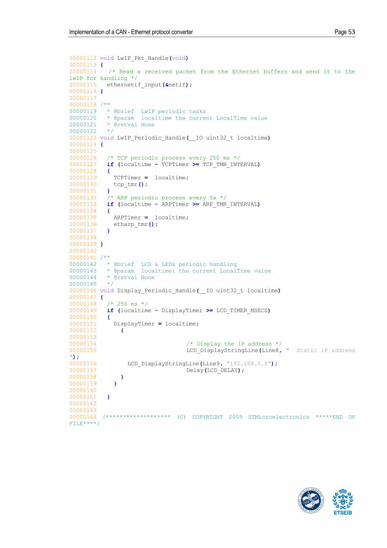
Implementation of a CAN - Ethernet protocol converter Page 53
00000112 void LwIP_Pkt_Handle(void)
00000113 {
00000114 /* Read a received packet from the Ethernet buffers and send it to the
lwIP for handling */
00000115 ethernetif_input(&netif);
00000116 }
00000117
00000118 /**
00000119 * @brief LwIP periodic tasks
00000120 * @param localtime the current LocalTime value
00000121 * @retval None
00000122 */
00000123 void LwIP_Periodic_Handle(__IO uint32_t localtime)
00000124 {
00000125
00000126 /* TCP periodic process every 250 ms */
00000127 if (localtime - TCPTimer >= TCP_TMR_INTERVAL)
00000128 {
00000129 TCPTimer = localtime;
00000130 tcp_tmr();
00000131 }
00000132 /* ARP periodic process every 5s */
00000133 if (localtime - ARPTimer >= ARP_TMR_INTERVAL)
00000134 {
00000135 ARPTimer = localtime;
00000136 etharp_tmr();
00000137 }
00000138
00000139 }
00000140
00000141 /**
00000142 * @brief LCD & LEDs periodic handling
00000143 * @param localtime: the current LocalTime value
00000144 * @retval None
00000145 */
00000146 void Display_Periodic_Handle(__IO uint32_t localtime)
00000147 {
00000148 /* 250 ms */
00000149 if (localtime - DisplayTimer >= LCD_TIMER_MSECS)
00000150 {
00000151 DisplayTimer = localtime;
00000152 {
00000153
00000154 /* Display the IP address */
00000155 LCD_DisplayStringLine(Line8, " Static IP address
");
00000156 LCD_DisplayStringLine(Line9, "192.168.0.8");
00000157 Delay(LCD_DELAY);
00000158 }
00000159 }
00000160
00000161 }
00000162
00000163
00000164 /******************* (C) COPYRIGHT 2009 STMicroelectronics *****END OF
FILE****/

Page 54 Report
10.7 Source code III: Interruptions
00000001 /**
00000002
******************************************************************************
00000003 * @file stm32f10x_it.c
00000004 * @author MCD Application Team
00000005 * @version V1.0.0
00000006 * @date 11/20/2009
00000007 * @brief Main Interrupt Service Routines.
00000008 * This file provides template for all exceptions handler and
00000009 * peripherals interrupt service routine.
00000010
******************************************************************************
00000011 * @copy
00000012 *
00000013 * THE PRESENT FIRMWARE WHICH IS FOR GUIDANCE ONLY AIMS AT PROVIDING
CUSTOMERS
00000014 * WITH CODING INFORMATION REGARDING THEIR PRODUCTS IN ORDER FOR THEM TO
SAVE
00000015 * TIME. AS A RESULT, STMICROELECTRONICS SHALL NOT BE HELD LIABLE FOR ANY
00000016 * DIRECT, INDIRECT OR CONSEQUENTIAL DAMAGES WITH RESPECT TO ANY CLAIMS
ARISING
00000017 * FROM THE CONTENT OF SUCH FIRMWARE AND/OR THE USE MADE BY CUSTOMERS OF
THE
00000018 * CODING INFORMATION CONTAINED HEREIN IN CONNECTION WITH THEIR PRODUCTS.
00000019 *
00000020 * <h2><center>© COPYRIGHT 2009 STMicroelectronics</center></h2>
00000021 */
00000022
00000023 /* Includes --------------------------------------------------------------
----*/
00000024 #include "stm32f10x_it.h"
00000025 #include "stm32_eth.h"
00000026 #include "main.h"
00000027 #include "stm32f10x_it.h"
00000028 #include "stm3210c_eval_lcd.h"
00000029 #include "stm32f10x_can.h"
00000030 #include <stdio.h>
00000031 #include <string.h>
00000032 #include <stdlib.h>
00000033
00000034 /* Private typedef -------------------------------------------------------
----*/
00000035 /* Private define --------------------------------------------------------
----*/
00000036 /* Private macro ---------------------------------------------------------
----*/
00000037 /* Private variables -----------------------------------------------------
----*/
00000038 CanRxMsg RxMessage;
00000039 char data[80];
00000040
00000041
00000042 /* Private function prototypes -------------------------------------------
----*/
00000043 extern void LwIP_Pkt_Handle(void);
00000044 extern void LCD_DisplayStringLine(uint8_t Line, uint8_t *ptr);
00000045 extern void LCD_ClearLine(uint8_t Line);
00000046 extern void Init_RxMes(CanRxMsg *RxMessage);
00000047
00000048 /* Private functions -----------------------------------------------------
----*/

Implementation of a CAN - Ethernet protocol converter Page 55
00000049
00000050
/******************************************************************************/
00000051 /* Cortex-M3 Processor Exceptions Handlers
*/
00000052
/******************************************************************************/
00000053
00000054 /**
00000055 * @brief This function handles NMI exception.
00000056 * @param None
00000057 * @retval None
00000058 */
00000059 void NMI_Handler(void)
00000060 {}
00000061
00000062 /**
00000063 * @brief This function handles Hard Fault exception.
00000064 * @param None
00000065 * @retval None
00000066 */
00000067 void HardFault_Handler(void)
00000068 {
00000069 /* Go to infinite loop when Hard Fault exception occurs */
00000070 while (1)
00000071 {}
00000072 }
00000073
00000074 /**
00000075 * @brief This function handles Memory Manage exception.
00000076 * @param None
00000077 * @retval None
00000078 */
00000079 void MemManage_Handler(void)
00000080 {
00000081 /* Go to infinite loop when Memory Manage exception occurs */
00000082 while (1)
00000083 {}
00000084 }
00000085
00000086 /**
00000087 * @brief This function handles Bus Fault exception.
00000088 * @param None
00000089 * @retval None
00000090 */
00000091 void BusFault_Handler(void)
00000092 {
00000093 /* Go to infinite loop when Bus Fault exception occurs */
00000094 while (1)
00000095 {}
00000096 }
00000097
00000098 /**
00000099 * @brief This function handles Usage Fault exception.
00000100 * @param None
00000101 * @retval None
00000102 */
00000103 void UsageFault_Handler(void)
00000104 {
00000105 /* Go to infinite loop when Usage Fault exception occurs */
00000106 while (1)
00000107 {}
00000108 }
00000109
00000110 /**

Page 56 Report
00000111 * @brief This function handles SVCall exception.
00000112 * @param None
00000113 * @retval None
00000114 */
00000115 void SVC_Handler(void)
00000116 {}
00000117
00000118 /**
00000119 * @brief This function handles Debug Monitor exception.
00000120 * @param None
00000121 * @retval None
00000122 */
00000123 void DebugMon_Handler(void)
00000124 {}
00000125
00000126 /**
00000127 * @brief This function handles PendSVC exception.
00000128 * @param None
00000129 * @retval None
00000130 */
00000131 void PendSV_Handler(void)
00000132 {}
00000133
00000134 /**
00000135 * @brief This function handles SysTick Handler.
00000136 * @param None
00000137 * @retval None
00000138 */
00000139 void SysTick_Handler(void)
00000140 {
00000141 /* Update the LocalTime by adding SYSTEMTICK_PERIOD_MS each SysTick
interrupt */
00000142 Time_Update();
00000143 }
00000144
00000145
/******************************************************************************/
00000146 /* STM32F10x Peripherals Interrupt Handlers
*/
00000147 /* Add here the Interrupt Handler for the used peripheral(s) (PPP), for
the */
00000148 /* available peripheral interrupt handler's name please refer to the
startup */
00000149 /* file (startup_stm32f10x_xx.s).
*/
00000150
/******************************************************************************/
00000151
00000152 /**
00000153 * @brief This function handles ETH interrupt request.
00000154 * @param None
00000155 * @retval None
00000156 */
00000157 void ETH_IRQHandler(void)
00000158 {
00000159 /* Handles all the received frames */
00000160 while(ETH_GetRxPktSize() != 0)
00000161 {
00000162 LwIP_Pkt_Handle();
00000163 }
00000164
00000165 /* Clear the Eth DMA Rx IT pending bits */
00000166 ETH_DMAClearITPendingBit(ETH_DMA_IT_R);
00000167 ETH_DMAClearITPendingBit(ETH_DMA_IT_NIS);

Implementation of a CAN - Ethernet protocol converter Page 57
00000168 }
00000169
00000170
00000171 ///**
00000172 // * @brief This function handles External lines 15 to 10 interrupt
request.
00000173 // * @param None
00000174 // * @retval None
00000175 // */
00000176 //void EXTI15_10_IRQHandler(void)
00000177 //{
00000178
00000179 // if(EXTI_GetITStatus(EXTI_LINE_IOE_ITLINE) != RESET)
00000180 // {
00000181 // static TS_STATE* TS_State;
00000182 //
00000183 // /* Check if the interrupt source is the Touch Screen */
00000184 // if (IOE_GetGITStatus(IOE_1_ADDR, IOE_TS_IT) & IOE_TS_IT)
00000185 // {
00000186 // /* Update the structure with the current position */
00000187 // TS_State = IOE_TS_GetState();
00000188 //
00000189 // if ((TS_State->TouchDetected) && (TS_State->Y < 220) && (TS_State-
>Y > 180))
00000190 // {
00000191 // if ((TS_State->X > 10) && (TS_State->X < 70))
00000192 // {
00000193 // LCD_DisplayStringLine(Line6, " LD4 ");
00000194 // STM_EVAL_LEDOn(LED4);
00000195 //
00000196 // /* Send out a TCP packet to toggle the server's led4 */
00000197 //
00000198 // }
00000199 // else if ((TS_State->X > 90) && (TS_State->X < 150))
00000200 // {
00000201 // LCD_DisplayStringLine(Line6, " LD3 ");
00000202 // STM_EVAL_LEDOn(LED3);
00000203 //
00000204 // /* Send out a TCP packet to toggle the server's led3 */
00000205 //
00000206 // }
00000207 // else if ((TS_State->X > 170) && (TS_State->X < 230))
00000208 // {
00000209 // LCD_DisplayStringLine(Line6, " LD2 ");
00000210 // STM_EVAL_LEDOn(LED2);
00000211 //
00000212 // /* Send out a TCP packet to toggle the server's led2 */
00000213 //
00000214 // }
00000215 // else if ((TS_State->X > 250) && (TS_State->X < 310))
00000216 // {
00000217 // LCD_DisplayStringLine(Line6, " LD1 ");
00000218 // STM_EVAL_LEDOn(LED1);
00000219 //
00000220 // /* Send out a TCP packet to toggle the server's led1 */
00000221 //
00000222 // }
00000223 // }
00000224 // else
00000225 // {
00000226 // STM_EVAL_LEDOff(LED1);
00000227 // STM_EVAL_LEDOff(LED2);
00000228 // STM_EVAL_LEDOff(LED3);
00000229 // STM_EVAL_LEDOff(LED4);
00000230 // }

Page 58 Report
00000231 //
00000232 // /* Clear the interrupt pending bits */
00000233 // IOE_ClearGITPending(IOE_1_ADDR, IOE_TS_IT);
00000234 // }
00000235 // else
00000236 // {
00000237 // IOE_ClearGITPending(IOE_1_ADDR, ALL_IT);
00000238 // IOE_ClearGITPending(IOE_2_ADDR, ALL_IT);
00000239 // }
00000240 //
00000241 // EXTI_ClearITPendingBit(EXTI_LINE_IOE_ITLINE);
00000242 // }
00000243 //}
00000244
00000245 /**
00000246 * @brief This function handles CAN1 Handler.
00000247 * @param None
00000248 * @retval None
00000249 */
00000250
00000251
00000252 #ifndef STM32F10X_CL
00000253 void USB_LP_CAN1_RX0_IRQHandler(void)
00000254 #else
00000255 void CAN1_RX0_IRQHandler(void)
00000256 #endif
00000257 {
00000258 STM_EVAL_LEDOn(LED3);
00000259 CAN_Receive(CAN1, CAN_FIFO0, &RxMessage);
00000260 //convert to string
00000261 sprintf(data, "%d %d %s",
RxMessage.StdId,RxMessage.DLC,RxMessage.Data);
00000262
00000263
00000264 }
00000265
00000266
00000267 /******************* (C) COPYRIGHT 2009 STMicroelectronics *****END OF
FILE****/

Implementation of a CAN - Ethernet protocol converter Page 59
10.8 Source code IV: helloworld.c
******************************************************************************
00000003 * @file helloworld.c
00000004 * @author MCD Application Team
00000005 * @version V1.0.0
00000006 * @date 11/20/2009
00000007 * @brief A hello world example based on a Telnet connection
00000008 * The application works as a server which wait for the client
request
00000009
******************************************************************************
00000010 * @copy
00000011 *
00000012 * THE PRESENT FIRMWARE WHICH IS FOR GUIDANCE ONLY AIMS AT PROVIDING
CUSTOMERS
00000013 * WITH CODING INFORMATION REGARDING THEIR PRODUCTS IN ORDER FOR THEM TO
SAVE
00000014 * TIME. AS A RESULT, STMICROELECTRONICS SHALL NOT BE HELD LIABLE FOR ANY
00000015 * DIRECT, INDIRECT OR CONSEQUENTIAL DAMAGES WITH RESPECT TO ANY CLAIMS
ARISING
00000016 * FROM THE CONTENT OF SUCH FIRMWARE AND/OR THE USE MADE BY CUSTOMERS OF
THE
00000017 * CODING INFORMATION CONTAINED HEREIN IN CONNECTION WITH THEIR PRODUCTS.
00000018 *
00000019 * <h2><center>© COPYRIGHT 2009 STMicroelectronics</center></h2>
00000020 */
00000021
00000022 /* Includes --------------------------------------------------------------
----*/
00000023 #include "helloworld.h"
00000024 #include "lwip/tcp.h"
00000025 #include <string.h>
00000026 #include "stm32f10x_can.h"
00000027 #include "stm32f10x_it.h"
00000028 #include "stm32_eth.h"
00000029 #include "main.h"
00000030 #include "stm32f10x_it.h"
00000031 #include "stm3210c_eval_lcd.h"
00000032 #include "stm32f10x_can.h"
00000033 #include <stdio.h>
00000034 #include <string.h>
00000035 #include <stdlib.h>
00000036
00000037 /* Private typedef -------------------------------------------------------
----*/
00000038 /* Private define --------------------------------------------------------
----*/
00000039
00000040 #define MAX_NAME_SIZE 32
00000041 extern CanRxMsg RxMessage;
00000042 extern char data;
00000043
00000044 /* Private macro ---------------------------------------------------------
----*/
00000045 /* Private variables -----------------------------------------------------
----*/
00000046 struct name
00000047 {
00000048 int length;
00000049 char bytes[MAX_NAME_SIZE];
00000050 };
00000051
00000052 /* Private function prototypes ------------------------ ------
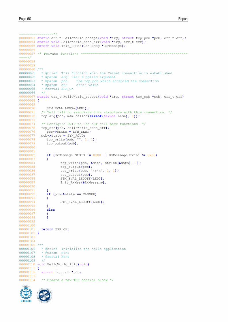
Page 60 Report
-----------------*/
00000053 static err_t HelloWorld_accept(void *arg, struct tcp_pcb *pcb, err_t err);
00000054 static void HelloWorld_conn_err(void *arg, err_t err);
00000055 extern void Init_RxMes(CanRxMsg *RxMessage);
00000056
00000057 /* Private functions -----------------------------------------------------
----*/
00000058
00000059
00000060 /**
00000061 * @brief This function when the Telnet connection is established
00000062 * @param arg user supplied argument
00000063 * @param pcb the tcp_pcb which accepted the connection
00000064 * @param err error value
00000065 * @retval ERR_OK
00000066 */
00000067 static err_t HelloWorld_accept(void *arg, struct tcp_pcb *pcb, err_t err)
00000068 {
00000069
00000070 STM_EVAL_LEDOn(LED1);
00000071 /* Tell LwIP to associate this structure with this connection. */
00000072 tcp_arg(pcb, mem_calloc(sizeof(struct name), 1));
00000073
00000074 /* Configure LwIP to use our call back functions. */
00000075 tcp_err(pcb, HelloWorld_conn_err);
00000076 pcb->state = SYN_SENT;
00000077 pcb->state = SYN_RCVD;
00000078 tcp_write(pcb, "", 1, 1);
00000079 tcp_output(pcb);
00000080
00000081
00000082 if (RxMessage.StdId != 0x00 || RxMessage.ExtId != 0x00)
00000083 {
00000084 tcp_write(pcb, &data, strlen(&data), 1);
00000085 tcp_output(pcb);
00000086 tcp_write(pcb, "\r\n", 2, 1);
00000087 tcp_output(pcb);
00000088 STM_EVAL_LEDOff(LED3);
00000089 Init_RxMes(&RxMessage);
00000090
00000091 }
00000092 if (pcb->state == CLOSED)
00000093 {
00000094 STM_EVAL_LEDOff(LED1);
00000095 }
00000096 else
00000097 {
00000098 }
00000099
00000100
00000101 return ERR_OK;
00000102 }
00000103
00000104
00000105 /**
00000106 * @brief Initialize the hello application
00000107 * @param None
00000108 * @retval None
00000109 */
00000110 void HelloWorld_init(void)
00000111 {
00000112 struct tcp_pcb *pcb;
00000113
00000114 /* Create a new TCP control block */
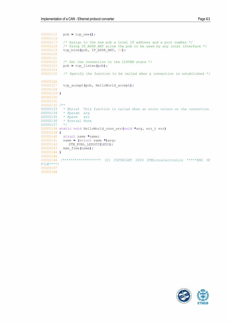
Implementation of a CAN - Ethernet protocol converter Page 61
00000115 pcb = tcp_new();
00000116
00000117 /* Assign to the new pcb a local IP address and a port number */
00000118 /* Using IP_ADDR_ANY allow the pcb to be used by any local interface */
00000119 tcp_bind(pcb, IP_ADDR_ANY, 23);
00000120
00000121
00000122 /* Set the connection to the LISTEN state */
00000123 pcb = tcp_listen(pcb);
00000124
00000125 /* Specify the function to be called when a connection is established */
00000126
00000127 tcp_accept(pcb, HelloWorld_accept);
00000128
00000129 }
00000130
00000131
00000132 /**
00000133 * @brief This function is called when an error occurs on the connection
00000134 * @param arg
00000135 * @parm err
00000136 * @retval None
00000137 */
00000138 static void HelloWorld_conn_err(void *arg, err_t err)
00000139 {
00000140 struct name *name;
00000141 name = (struct name *)arg;
00000142 STM_EVAL_LEDOff(LED1);
00000143 mem_free(name);
00000144 }
00000145
00000146 /******************* (C) COPYRIGHT 2009 STMicroelectronics *****END OF
FILE****/
00000147
00000148

Page 62 Report
10.9 Source code V: Board configuration (stm32f107.c)
******************************************************************************
00000003 * @file stm32f107.c
00000004 * @author MCD Application Team
00000005 * @version V1.0.0
00000006 * @date 11/20/2009
00000007 * @brief STM32F107 hardware configuration
00000008
******************************************************************************
00000009 * @copy
00000010 *
00000011 * THE PRESENT FIRMWARE WHICH IS FOR GUIDANCE ONLY AIMS AT PROVIDING
CUSTOMERS
00000012 * WITH CODING INFORMATION REGARDING THEIR PRODUCTS IN ORDER FOR THEM TO
SAVE
00000013 * TIME. AS A RESULT, STMICROELECTRONICS SHALL NOT BE HELD LIABLE FOR ANY
00000014 * DIRECT, INDIRECT OR CONSEQUENTIAL DAMAGES WITH RESPECT TO ANY CLAIMS
ARISING
00000015 * FROM THE CONTENT OF SUCH FIRMWARE AND/OR THE USE MADE BY CUSTOMERS OF
THE
00000016 * CODING INFORMATION CONTAINED HEREIN IN CONNECTION WITH THEIR PRODUCTS.
00000017 *
00000018 * <h2><center>© COPYRIGHT 2009 STMicroelectronics</center></h2>
00000019 */
00000020
00000021 /* Includes --------------------------------------------------------------
----*/
00000022 #include "stm32_eth.h"
00000023 #include "stm32f107.h"
00000024
00000025 /* Private typedef -------------------------------------------------------
----*/
00000026 /* Private define --------------------------------------------------------
----*/
00000027 #define DP83848_PHY /* Ethernet pins mapped on STM3210C-EVAL Board
*/
00000028 #define PHY_ADDRESS 0x01 /* Relative to STM3210C-EVAL Board */
00000029
00000030 //#define MII_MODE /* MII mode for STM3210C-EVAL Board (MB784)
(check jumpers setting) */
00000031 #define RMII_MODE /* RMII mode for STM3210C-EVAL Board (MB784)
(check jumpers setting) */
00000032
00000033 /*--------------- LCD Messages ---------------*/
00000034 #define MESSAGE1 " STM32F107 "
00000035 #define MESSAGE2 " on work "
00000036
00000037 /* Private macro ---------------------------------------------------------
----*/
00000038 /* Private variables -----------------------------------------------------
----*/
00000039 /* Private functions -----------------------------------------------------
----*/
00000040 void GPIO_Configuration(void);
00000041 void NVIC_Configuration(void);
00000042 void ADC_Configuration(void);
00000043 void Ethernet_Configuration(void);
00000044
00000045 /**

Implementation of a CAN - Ethernet protocol converter Page 63
00000046 * @brief Setup STM32 system (clocks, Ethernet, GPIO, NVIC) and
STM3210C-EVAL resources.
00000047 * @param None
00000048 * @retval None
00000049 */
00000050 void System_Setup(void)
00000051 {
00000052 RCC_ClocksTypeDef RCC_Clocks;
00000053
00000054 /* Setup STM32 clock, PLL and Flash configuration) */
00000055 SystemInit();
00000056
00000057 /* Enable USART2 clock */
00000058 RCC_APB1PeriphClockCmd(RCC_APB1Periph_USART2, ENABLE);
00000059
00000060
00000061 /* Enable ETHERNET clock */
00000062 RCC_AHBPeriphClockCmd(RCC_AHBPeriph_ETH_MAC | RCC_AHBPeriph_ETH_MAC_Tx |
00000063 RCC_AHBPeriph_ETH_MAC_Rx, ENABLE);
00000064
00000065 /* Enable GPIOs and ADC1 clocks */
00000066 RCC_APB2PeriphClockCmd(RCC_APB2Periph_GPIOA | RCC_APB2Periph_GPIOB |
RCC_APB2Periph_GPIOC |
00000067 RCC_APB2Periph_GPIOD | RCC_APB2Periph_GPIOE |
RCC_APB2Periph_AFIO |
00000068 RCC_APB2Periph_ADC1, ENABLE);
00000069
00000070 /* NVIC configuration */
00000071 NVIC_Configuration();
00000072
00000073 /* ADC configuration */
00000074 ADC_Configuration();
00000075
00000076 /* Configure the GPIO ports */
00000077 GPIO_Configuration();
00000078
00000079 /* Initialize the STM3210C-EVAL's LCD */
00000080 STM3210C_LCD_Init();
00000081
00000082 /* Initialize STM3210C-EVAL's LEDs */
00000083 STM_EVAL_LEDInit(LED1);
00000084 STM_EVAL_LEDInit(LED2);
00000085 STM_EVAL_LEDInit(LED3);
00000086 STM_EVAL_LEDInit(LED4);
00000087
00000088 /* Turn on leds available on STM3210X-EVAL */
00000089 // STM_EVAL_LEDOn(LED1);
00000090 // STM_EVAL_LEDOn(LED2);
00000091 // STM_EVAL_LEDOn(LED3);
00000092 // STM_EVAL_LEDOn(LED4);
00000093
00000094 /* Clear the LCD */
00000095 LCD_Clear(Magenta);
00000096
00000097 /* Set the LCD Back Color */
00000098 LCD_SetBackColor(Magenta);
00000099
00000100 /* Set the LCD Text Color */
00000101 LCD_SetTextColor(White);
00000102
00000103 /* Display message on the LCD*/
00000104 LCD_DisplayStringLine(Line0, MESSAGE1);
00000105 LCD_DisplayStringLine(Line1, MESSAGE2);
00000106
00000107 /* Configure the Ethernet peripheral */

Page 64 Report
00000108 Ethernet_Configuration();
00000109
00000110 /* SystTick configuration: an interrupt every 10ms */
00000111 RCC_GetClocksFreq(&RCC_Clocks);
00000112 SysTick_Config(RCC_Clocks.SYSCLK_Frequency / 100);
00000113
00000114 /* Update the SysTick IRQ priority should be higher than the Ethernet
IRQ */
00000115 /* The Localtime should be updated during the Ethernet packets
processing */
00000116 NVIC_SetPriority (SysTick_IRQn, 1);
00000117
00000118 /* Configure the Key button */
00000119 STM_EVAL_PBInit(Button_KEY, Mode_GPIO);
00000120 }
00000121
00000122 /**
00000123 * @brief Configures the Ethernet Interface
00000124 * @param None
00000125 * @retval None
00000126 */
00000127 void Ethernet_Configuration(void)
00000128 {
00000129 ETH_InitTypeDef ETH_InitStructure;
00000130
00000131 /* MII/RMII Media interface selection ----------------------------------
--------*/
00000132 #ifdef MII_MODE /* Mode MII with STM3210C-EVAL */
00000133 GPIO_ETH_MediaInterfaceConfig(GPIO_ETH_MediaInterface_MII);
00000134
00000135 /* Get HSE clock = 25MHz on PA8 pin (MCO) */
00000136 RCC_MCOConfig(RCC_MCO_HSE);
00000137
00000138 #elif defined RMII_MODE /* Mode RMII with STM3210C-EVAL */
00000139 GPIO_ETH_MediaInterfaceConfig(GPIO_ETH_MediaInterface_RMII);
00000140
00000141 /* Set PLL3 clock output to 50MHz (25MHz /5 *10 =50MHz) */
00000142 RCC_PLL3Config(RCC_PLL3Mul_10);
00000143 /* Enable PLL3 */
00000144 RCC_PLL3Cmd(ENABLE);
00000145 /* Wait till PLL3 is ready */
00000146 while (RCC_GetFlagStatus(RCC_FLAG_PLL3RDY) == RESET)
00000147 {}
00000148
00000149 /* Get PLL3 clock on PA8 pin (MCO) */
00000150 RCC_MCOConfig(RCC_MCO_PLL3CLK);
00000151 #endif
00000152
00000153 /* Reset ETHERNET on AHB Bus */
00000154 ETH_DeInit();
00000155
00000156 /* Software reset */
00000157 ETH_SoftwareReset();
00000158
00000159 /* Wait for software reset */
00000160 while (ETH_GetSoftwareResetStatus() == SET);
00000161
00000162 /* ETHERNET Configuration ----------------------------------------------
--------*/
00000163 /* Call ETH_StructInit if you don't like to configure all
ETH_InitStructure parameter */
00000164 ETH_StructInit(Ð_InitStructure);
00000165
00000166 /* Fill ETH_InitStructure parametrs */

Implementation of a CAN - Ethernet protocol converter Page 65
00000167 /*------------------------ MAC -----------------------------------*/
00000168 ETH_InitStructure.ETH_AutoNegotiation = ETH_AutoNegotiation_Enable ;
00000169 ETH_InitStructure.ETH_LoopbackMode = ETH_LoopbackMode_Disable;
00000170 ETH_InitStructure.ETH_RetryTransmission = ETH_RetryTransmission_Disable;
00000171 ETH_InitStructure.ETH_AutomaticPadCRCStrip =
ETH_AutomaticPadCRCStrip_Disable;
00000172 ETH_InitStructure.ETH_ReceiveAll = ETH_ReceiveAll_Disable;
00000173 ETH_InitStructure.ETH_BroadcastFramesReception =
ETH_BroadcastFramesReception_Enable;
00000174 ETH_InitStructure.ETH_PromiscuousMode = ETH_PromiscuousMode_Disable;
00000175 ETH_InitStructure.ETH_MulticastFramesFilter =
ETH_MulticastFramesFilter_Perfect;
00000176 ETH_InitStructure.ETH_UnicastFramesFilter =
ETH_UnicastFramesFilter_Perfect;
00000177 #ifdef CHECKSUM_BY_HARDWARE
00000178 ETH_InitStructure.ETH_ChecksumOffload = ETH_ChecksumOffload_Enable;
00000179 #endif
00000180
00000181 /*------------------------ DMA -----------------------------------*/
00000182
00000183 /* When we use the Checksum offload feature, we need to enable the Store
and Forward mode:
00000184 the store and forward guarantee that a whole frame is stored in the
FIFO, so the MAC can insert/verify the checksum,
00000185 if the checksum is OK the DMA can handle the frame otherwise the frame
is dropped */
00000186 ETH_InitStructure.ETH_DropTCPIPChecksumErrorFrame =
ETH_DropTCPIPChecksumErrorFrame_Enable;
00000187 ETH_InitStructure.ETH_ReceiveStoreForward =
ETH_ReceiveStoreForward_Enable;
00000188 ETH_InitStructure.ETH_TransmitStoreForward =
ETH_TransmitStoreForward_Enable;
00000189
00000190 ETH_InitStructure.ETH_ForwardErrorFrames =
ETH_ForwardErrorFrames_Disable;
00000191 ETH_InitStructure.ETH_ForwardUndersizedGoodFrames =
ETH_ForwardUndersizedGoodFrames_Disable;
00000192 ETH_InitStructure.ETH_SecondFrameOperate =
ETH_SecondFrameOperate_Enable;
00000193 ETH_InitStructure.ETH_AddressAlignedBeats =
ETH_AddressAlignedBeats_Enable;
00000194 ETH_InitStructure.ETH_FixedBurst = ETH_FixedBurst_Enable;
00000195 ETH_InitStructure.ETH_RxDMABurstLength = ETH_RxDMABurstLength_32Beat;
00000196 ETH_InitStructure.ETH_TxDMABurstLength = ETH_TxDMABurstLength_32Beat;
00000197 ETH_InitStructure.ETH_DMAArbitration =
ETH_DMAArbitration_RoundRobin_RxTx_2_1;
00000198
00000199 /* Configure Ethernet */
00000200 ETH_Init(Ð_InitStructure, PHY_ADDRESS);
00000201
00000202 /* Enable the Ethernet Rx Interrupt */
00000203 ETH_DMAITConfig(ETH_DMA_IT_NIS | ETH_DMA_IT_R, ENABLE);
00000204
00000205 }
00000206
00000207 /**
00000208 * @brief Configures the different GPIO ports.
00000209 * @param None
00000210 * @retval None
00000211 */
00000212 void GPIO_Configuration(void)
00000213 {
00000214 GPIO_InitTypeDef GPIO_InitStructure;
00000215
00000216 /* ETHERNET pins configuration */

Page 66 Report
00000217 /* AF Output Push Pull:
00000218 - ETH_MII_MDIO / ETH_RMII_MDIO: PA2
00000219 - ETH_MII_MDC / ETH_RMII_MDC: PC1
00000220 - ETH_MII_TXD2: PC2
00000221 - ETH_MII_TX_EN / ETH_RMII_TX_EN: PB11
00000222 - ETH_MII_TXD0 / ETH_RMII_TXD0: PB12
00000223 - ETH_MII_TXD1 / ETH_RMII_TXD1: PB13
00000224 - ETH_MII_PPS_OUT / ETH_RMII_PPS_OUT: PB5
00000225 - ETH_MII_TXD3: PB8 */
00000226
00000227 /* Configure PA2 as alternate function push-pull */
00000228 GPIO_InitStructure.GPIO_Pin = GPIO_Pin_2;
00000229 GPIO_InitStructure.GPIO_Speed = GPIO_Speed_50MHz;
00000230 GPIO_InitStructure.GPIO_Mode = GPIO_Mode_AF_PP;
00000231 GPIO_Init(GPIOA, &GPIO_InitStructure);
00000232
00000233 /* Configure PC1, PC2 and PC3 as alternate function push-pull */
00000234 GPIO_InitStructure.GPIO_Pin = GPIO_Pin_1 | GPIO_Pin_2;
00000235 GPIO_InitStructure.GPIO_Speed = GPIO_Speed_50MHz;
00000236 GPIO_InitStructure.GPIO_Mode = GPIO_Mode_AF_PP;
00000237 GPIO_Init(GPIOC, &GPIO_InitStructure);
00000238
00000239 /* Configure PB5, PB8, PB11, PB12 and PB13 as alternate function push-
pull */
00000240 GPIO_InitStructure.GPIO_Pin = GPIO_Pin_5 | GPIO_Pin_8 | GPIO_Pin_11 |
00000241 GPIO_Pin_12 | GPIO_Pin_13;
00000242 GPIO_InitStructure.GPIO_Speed = GPIO_Speed_50MHz;
00000243 GPIO_InitStructure.GPIO_Mode = GPIO_Mode_AF_PP;
00000244 GPIO_Init(GPIOB, &GPIO_InitStructure);
00000245
00000246 /**************************************************************/
00000247 /* For Remapped Ethernet pins */
00000248 /*************************************************************/
00000249 /* Input (Reset Value):
00000250 - ETH_MII_CRS CRS: PA0
00000251 - ETH_MII_RX_CLK / ETH_RMII_REF_CLK: PA1
00000252 - ETH_MII_COL: PA3
00000253 - ETH_MII_RX_DV / ETH_RMII_CRS_DV: PD8
00000254 - ETH_MII_TX_CLK: PC3
00000255 - ETH_MII_RXD0 / ETH_RMII_RXD0: PD9
00000256 - ETH_MII_RXD1 / ETH_RMII_RXD1: PD10
00000257 - ETH_MII_RXD2: PD11
00000258 - ETH_MII_RXD3: PD12
00000259 - ETH_MII_RX_ER: PB10 */
00000260
00000261 /* ETHERNET pins remapp in STM3210C-EVAL board: RX_DV and RxD[3:0] */
00000262 GPIO_PinRemapConfig(GPIO_Remap_ETH, ENABLE);
00000263
00000264 /* Configure PA0, PA1 and PA3 as input */
00000265 GPIO_InitStructure.GPIO_Pin = GPIO_Pin_0 | GPIO_Pin_1 | GPIO_Pin_3;
00000266 GPIO_InitStructure.GPIO_Speed = GPIO_Speed_50MHz;
00000267 GPIO_InitStructure.GPIO_Mode = GPIO_Mode_IN_FLOATING;
00000268 GPIO_Init(GPIOA, &GPIO_InitStructure);
00000269
00000270 /* Configure PB10 as input */
00000271 GPIO_InitStructure.GPIO_Pin = GPIO_Pin_10;
00000272 GPIO_InitStructure.GPIO_Speed = GPIO_Speed_50MHz;
00000273 GPIO_InitStructure.GPIO_Mode = GPIO_Mode_IN_FLOATING;
00000274 GPIO_Init(GPIOB, &GPIO_InitStructure);
00000275
00000276 /* Configure PC3 as input */
00000277 GPIO_InitStructure.GPIO_Pin = GPIO_Pin_3;
00000278 GPIO_InitStructure.GPIO_Speed = GPIO_Speed_50MHz;
00000279 GPIO_InitStructure.GPIO_Mode = GPIO_Mode_IN_FLOATING;

Implementation of a CAN - Ethernet protocol converter Page 67
00000280 GPIO_Init(GPIOC, &GPIO_InitStructure);
00000281
00000282 /* Configure PD8, PD9, PD10, PD11 and PD12 as input */
00000283 GPIO_InitStructure.GPIO_Pin = GPIO_Pin_8 | GPIO_Pin_9 | GPIO_Pin_10 |
GPIO_Pin_11 | GPIO_Pin_12;
00000284 GPIO_InitStructure.GPIO_Speed = GPIO_Speed_50MHz;
00000285 GPIO_InitStructure.GPIO_Mode = GPIO_Mode_IN_FLOATING;
00000286 GPIO_Init(GPIOD, &GPIO_InitStructure); /**/
00000287
00000288 /* ADC Channel14 config ------------------------------------------------
--------*/
00000289 /* Relative to STM3210D-EVAL Board */
00000290 /* Configure PC.04 (ADC Channel14) as analog input ---------------------
----*/
00000291 GPIO_InitStructure.GPIO_Pin = GPIO_Pin_4;
00000292 GPIO_InitStructure.GPIO_Mode = GPIO_Mode_AIN;
00000293 GPIO_Init(GPIOC, &GPIO_InitStructure);
00000294
00000295 /* MCO pin configuration------------------------------------------------
- */
00000296 /* Configure MCO (PA8) as alternate function push-pull */
00000297 GPIO_InitStructure.GPIO_Pin = GPIO_Pin_8;
00000298 GPIO_InitStructure.GPIO_Speed = GPIO_Speed_50MHz;
00000299 GPIO_InitStructure.GPIO_Mode = GPIO_Mode_AF_PP;
00000300 GPIO_Init(GPIOA, &GPIO_InitStructure);
00000301
00000302 }
00000303
00000304 /**
00000305 * @brief Configures the ADC.
00000306 * @param None
00000307 * @retval None
00000308 */
00000309 void ADC_Configuration(void)
00000310 {
00000311 ADC_InitTypeDef ADC_InitStructure;
00000312
00000313 /* ADC1 Configuration --------------------------------------------------
----*/
00000314 ADC_InitStructure.ADC_Mode = ADC_Mode_Independent;
00000315 ADC_InitStructure.ADC_ScanConvMode = DISABLE;
00000316 ADC_InitStructure.ADC_ContinuousConvMode = ENABLE;
00000317 ADC_InitStructure.ADC_ExternalTrigConv = ADC_ExternalTrigConv_None;
00000318 ADC_InitStructure.ADC_DataAlign = ADC_DataAlign_Right;
00000319 ADC_InitStructure.ADC_NbrOfChannel = 1;
00000320 ADC_Init(ADC1, &ADC_InitStructure);
00000321
00000322 /* ADC1 regular channel14 configuration */
00000323 ADC_RegularChannelConfig(ADC1, ADC_Channel_14, 1,
ADC_SampleTime_13Cycles5);
00000324
00000325 /* Enable ADC1 */
00000326 ADC_Cmd(ADC1, ENABLE);
00000327
00000328 /* Start ADC1 Software Conversion */
00000329 ADC_SoftwareStartConvCmd(ADC1, ENABLE);
00000330 }
00000331
00000332 /**
00000333 * @brief Configures the nested vectored interrupt controller.
00000334 * @param None
00000335 * @retval None
00000336 */
00000337 void NVIC_Configuration(void)
00000338 {

Page 68 Report
00000339 NVIC_InitTypeDef NVIC_InitStructure;
00000340
00000341 /* Set the Vector Table base location at 0x08000000 */
00000342 NVIC_SetVectorTable(NVIC_VectTab_FLASH, 0x0);
00000343
00000344 /* 2 bit for pre-emption priority, 2 bits for subpriority */
00000345 NVIC_PriorityGroupConfig(NVIC_PriorityGroup_2);
00000346
00000347 /* Enable the Ethernet global Interrupt */
00000348 NVIC_InitStructure.NVIC_IRQChannel = ETH_IRQn;
00000349 NVIC_InitStructure.NVIC_IRQChannelPreemptionPriority = 2;
00000350 NVIC_InitStructure.NVIC_IRQChannelSubPriority = 0;
00000351 NVIC_InitStructure.NVIC_IRQChannelCmd = ENABLE;
00000352 NVIC_Init(&NVIC_InitStructure);
00000353
00000354 }
00000355
00000356 /******************* (C) COPYRIGHT 2009 STMicroelectronics *****END OF
FILE****/