Embed Size (px)
Citation preview

Campus Wired LAN Deployment Using Cisco Validated Designs
Dana Daum, Communications Architect
BRKCRS-1500
• Introduction to the Campus Wired LAN Deployment CVD
• Access Layer Deployment
• Distribution Layer Deployment
• Core Layer Deployment
• Conclusion
Agenda
© 2016 Cisco and/or its affiliates. All rights reserved. Cisco Public 4
BRKCRS-1500 Abstract: Campus Wired LAN Deployment Using Cisco Validated DesignsThis session is an introduction to LAN design and deployment best practices covered in the Campus Wired LAN design and deployment guides - part of the Cisco Validated Design (CVD) body of work. LAN deployments from single switch remote sites to large multi-building campuses are detailed.
Cisco Validated Design offers a framework for design guidance based on common use cases, along with technology design guides focusing on deployment details, including products and best practices, accelerating the adoption of technology.
The session discusses the consistent enablement of capabilities such as high availability, quality of service, multicast, and security across a range of Cisco LAN platforms. Also included are the decision criteria that can help an organization choose between platforms. The cornerstones of the approach and techniques discussed in this session are real-world use cases, prescriptive design guidance, and modular architectural components.
Though introductory, attendees for this session will benefit from an understanding of LAN switching and routing fundamentals equivalent to a CCNA level for a brief exploration of some intermediate topics.
BRKCRS-1500
• Introduction to the Campus Wired LAN Deployment CVD
• Access Layer Deployment
• Distribution Layer Deployment
• Core Layer Deployment
• Conclusion
Agenda
© 2016 Cisco and/or its affiliates. All rights reserved. Cisco Public 6
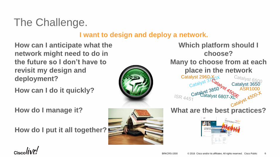
The Challenge.I want to design and deploy a network.
Which platform should I
choose?
Many to choose from at each
place in the network
What are the best practices?How do I manage it?
How do I put it all together?
How can I do it quickly?
How can I anticipate what the
network might need to do in
the future so I don’t have to
revisit my design and
deployment? Catalyst 2960-X
ASR1000Catalyst 3650
BRKCRS-1500
© 2016 Cisco and/or its affiliates. All rights reserved. Cisco Public 7
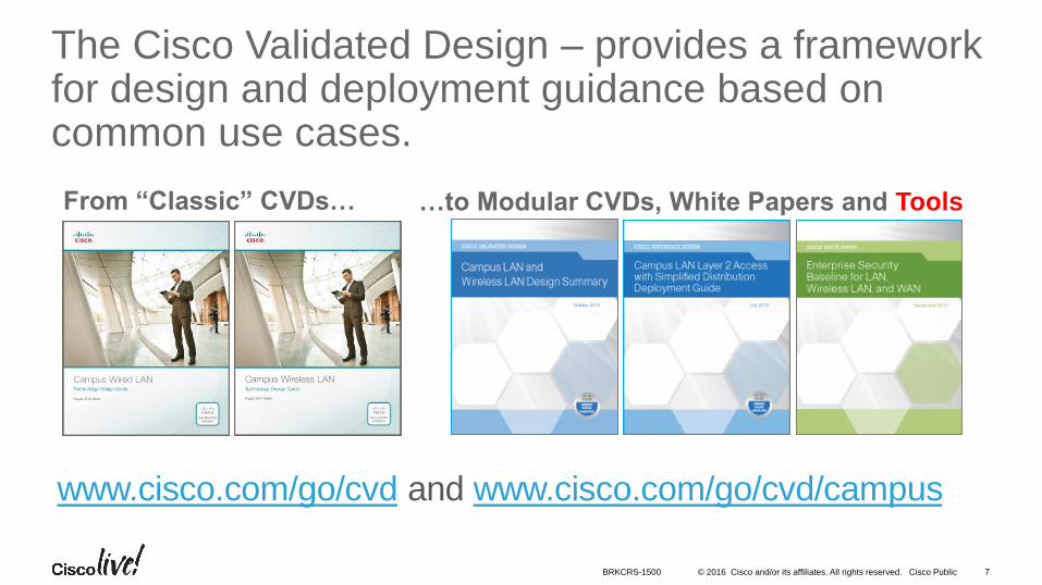
The Cisco Validated Design – provides a framework for design and deployment guidance based on common use cases.
From “Classic” CVDs… …to Modular CVDs, White Papers and Tools
www.cisco.com/go/cvd and www.cisco.com/go/cvd/campus
BRKCRS-1500
© 2016 Cisco and/or its affiliates. All rights reserved. Cisco Public 8
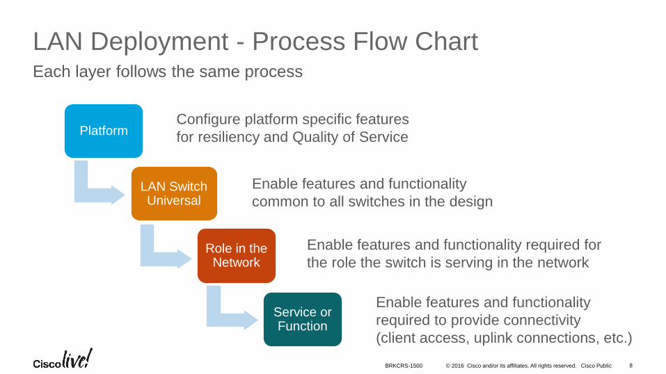
LAN Deployment - Process Flow ChartEach layer follows the same process
PlatformConfigure platform specific features
for resiliency and Quality of Service
LAN Switch Universal
Enable features and functionality
common to all switches in the design
Role in the Network
Enable features and functionality required for
the role the switch is serving in the network
Service or Function
Enable features and functionality
required to provide connectivity
(client access, uplink connections, etc.)
BRKCRS-1500
© 2016 Cisco and/or its affiliates. All rights reserved. Cisco Public
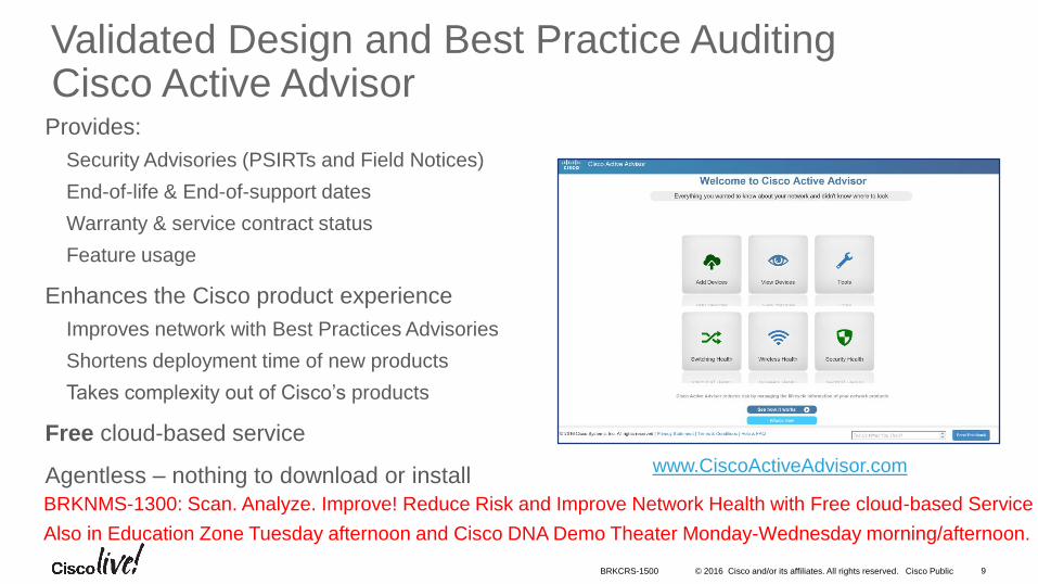
Validated Design and Best Practice AuditingCisco Active Advisor
• Provides:
• Security Advisories (PSIRTs and Field Notices)
• End-of-life & End-of-support dates
• Warranty & service contract status
• Feature usage
• Enhances the Cisco product experience
• Improves network with Best Practices Advisories
• Shortens deployment time of new products
• Takes complexity out of Cisco’s products
• Free cloud-based service
• Agentless – nothing to download or installwww.CiscoActiveAdvisor.com
BRKCRS-1500 9
BRKNMS-1300: Scan. Analyze. Improve! Reduce Risk and Improve Network Health with Free cloud-based Service
Also in Education Zone Tuesday afternoon and Cisco DNA Demo Theater Monday-Wednesday morning/afternoon.
© 2016 Cisco and/or its affiliates. All rights reserved. Cisco Public 10
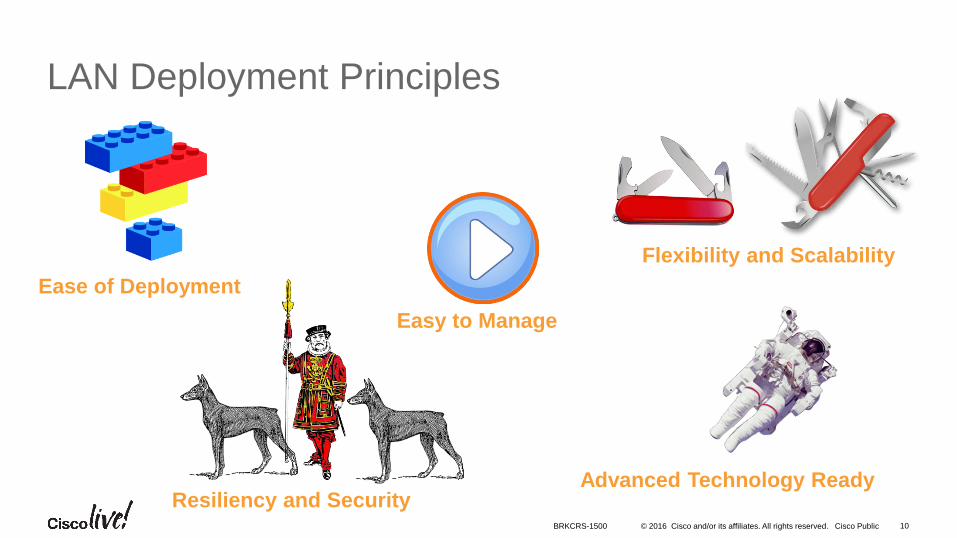
LAN Deployment Principles
Flexibility and Scalability
Ease of Deployment
Resiliency and Security
Easy to Manage
Advanced Technology Ready
BRKCRS-1500
© 2016 Cisco and/or its affiliates. All rights reserved. Cisco Public 11
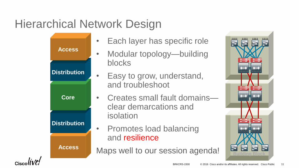
Hierarchical Network Design
Building Block
Access
Distribution
Core
Distribution
Access
• Each layer has specific role
• Modular topology—building blocks
• Easy to grow, understand, and troubleshoot
• Creates small fault domains—clear demarcations and isolation
• Promotes load balancing and resilience
Maps well to our session agenda!
BRKCRS-1500
© 2016 Cisco and/or its affiliates. All rights reserved. Cisco Public 12BRKCRS-1500
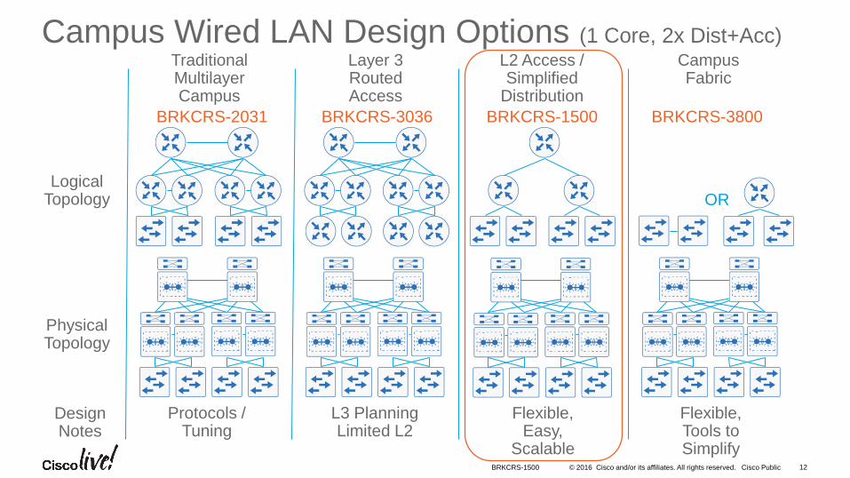
Campus Wired LAN Design Options (1 Core, 2x Dist+Acc)Traditional Multilayer Campus
Layer 3 Routed Access
L2 Access / Simplified
Distribution
Campus Fabric
Physical Topology
Logical Topology
Design Notes
OR
BRKCRS-3800BRKCRS-3036 BRKCRS-1500BRKCRS-2031
Protocols / Tuning
L3 Planning Limited L2
Flexible, Easy,
Scalable
Flexible, Tools to Simplify
© 2016 Cisco and/or its affiliates. All rights reserved. Cisco Public 13
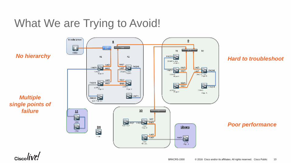
What We are Trying to Avoid!
No hierarchy
Poor performance
Hard to troubleshoot
Multiple
single points of
failure
BRKCRS-1500
• Introduction to the Campus Wired LAN Deployment CVD
• Access Layer Deployment
• Attributes and platform choices
• Platform Specific
• Global Options
• Client facing interfaces
• Uplinks to Distribution Layer
• Distribution Layer Deployment
• Core Layer Deployment
• Conclusion
Agenda
© 2016 Cisco and/or its affiliates. All rights reserved. Cisco Public
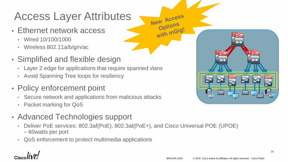
Access Layer Attributes
15
• Ethernet network access• Wired 10/100/1000
• Wireless 802.11a/b/g/n/ac
• Simplified and flexible design• Layer 2 edge for applications that require spanned vlans
• Avoid Spanning Tree loops for resiliency
• Policy enforcement point• Secure network and applications from malicious attacks
• Packet marking for QoS
• Advanced Technologies support• Deliver PoE services: 802.3af(PoE), 802.3at(PoE+), and Cisco Universal POE (UPOE)
– 60watts per port
• QoS enforcement to protect multimedia applications
BRKCRS-1500
© 2016 Cisco and/or its affiliates. All rights reserved. Cisco Public 16
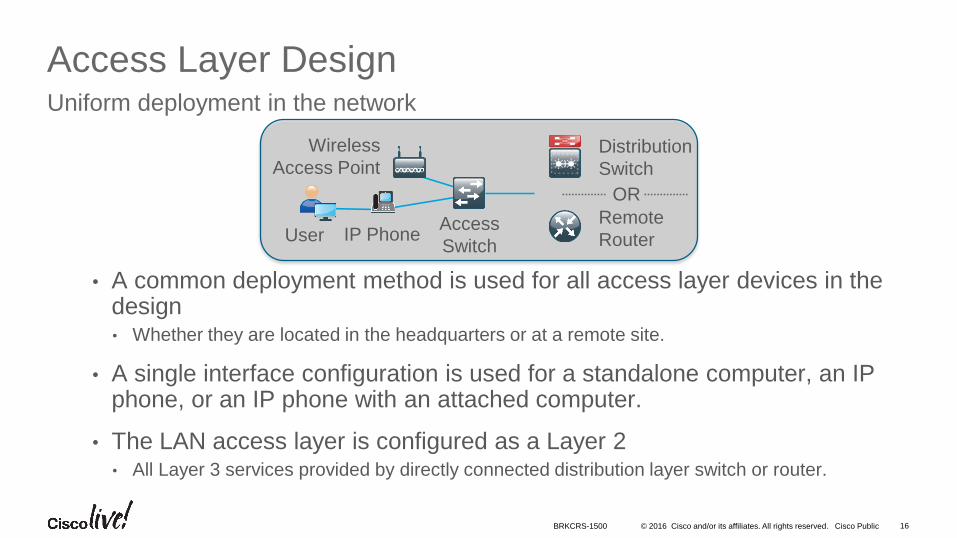
Access Layer DesignUniform deployment in the network
• A common deployment method is used for all access layer devices in the design • Whether they are located in the headquarters or at a remote site.
• A single interface configuration is used for a standalone computer, an IP phone, or an IP phone with an attached computer.
• The LAN access layer is configured as a Layer 2 • All Layer 3 services provided by directly connected distribution layer switch or router.
Wireless
Access Point
User IP PhoneAccess
Switch
Distribution
Switch
OR
Remote
Router
BRKCRS-1500
© 2016 Cisco and/or its affiliates. All rights reserved. Cisco Public
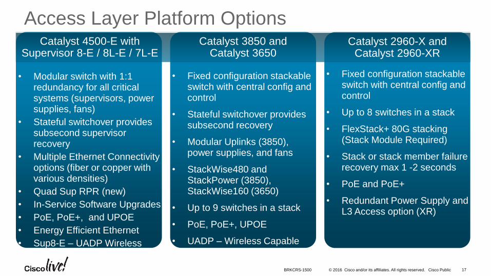
• Fixed configuration stackable switch with central config and control
• Stateful switchover provides subsecond recovery
• Modular Uplinks (3850), power supplies, and fans
• StackWise480 and StackPower (3850), StackWise160 (3650)
• Up to 9 switches in a stack
• PoE, PoE+, UPOE
• UADP – Wireless Capable
• Fixed configuration stackable switch with central config and control
• Up to 8 switches in a stack
• FlexStack+ 80G stacking(Stack Module Required)
• Stack or stack member failure recovery max 1 -2 seconds
• PoE and PoE+
• Redundant Power Supply and L3 Access option (XR)
17BRKCRS-1500
Access Layer Platform Options
• Modular switch with 1:1 redundancy for all critical systems (supervisors, power supplies, fans)
• Stateful switchover provides subsecond supervisor recovery
• Multiple Ethernet Connectivity options (fiber or copper with various densities)
• Quad Sup RPR (new)
• In-Service Software Upgrades
• PoE, PoE+, and UPOE
• Energy Efficient Ethernet
• Sup8-E – UADP Wireless
Catalyst 3850 and Catalyst 3650
Catalyst 2960-X andCatalyst 2960-XR
Catalyst 4500-E with Supervisor 8-E / 8L-E / 7L-E
• Introduction to the Campus Wired LAN Deployment CVD
• Access Layer Deployment
• Attributes and platform choices
• Platform Specific
• Global Options
• Client facing interfaces
• Uplinks to Distribution Layer
• Distribution Layer Deployment
• Core Layer Deployment
• Conclusion
Agenda
© 2016 Cisco and/or its affiliates. All rights reserved. Cisco Public
Single Logical Switch
S3S2S1
Single Logical Switch
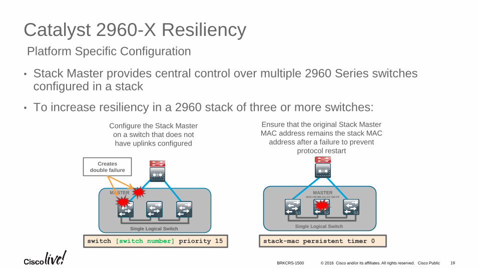
Configure the Stack Master
on a switch that does not
have uplinks configured
S3S2S1
19
Catalyst 2960-X Resiliency
• Stack Master provides central control over multiple 2960 Series switches configured in a stack
• To increase resiliency in a 2960 stack of three or more switches:
Platform Specific Configuration
MASTER
Creates
double failure
Ensure that the original Stack Master
MAC address remains the stack MAC
address after a failure to prevent
protocol restart
stack-mac persistent timer 0
MASTERMAC=00:BB:AA:CC:DD:FF
switch [switch number] priority 15
BRKCRS-1500
© 2016 Cisco and/or its affiliates. All rights reserved. Cisco Public 20
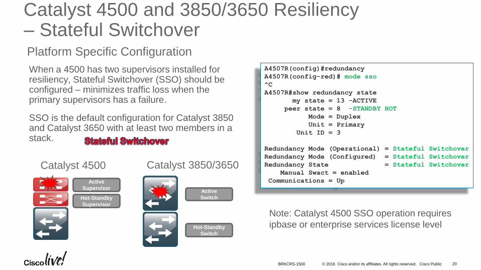
Catalyst 4500 and 3850/3650 Resiliency– Stateful SwitchoverPlatform Specific Configuration
When a 4500 has two supervisors installed for resiliency, Stateful Switchover (SSO) should be configured – minimizes traffic loss when the primary supervisors has a failure.
SSO is the default configuration for Catalyst 3850 and Catalyst 3650 with at least two members in a stack.
A4507R(config)#redundancy
A4507R(config-red)# mode sso
^C
A4507R#show redundancy state
my state = 13 -ACTIVE
peer state = 8 -STANDBY HOT
Mode = Duplex
Unit = Primary
Unit ID = 3
Redundancy Mode (Operational) = Stateful Switchover
Redundancy Mode (Configured) = Stateful Switchover
Redundancy State = Stateful Switchover
Manual Swact = enabled
Communications = Up
Hot-Standby
Supervisor
Active
Supervisor
Note: Catalyst 4500 SSO operation requires
ipbase or enterprise services license levelHot-Standby
Switch
Active
Switch
Catalyst 4500 Catalyst 3850/3650
BRKCRS-1500
© 2016 Cisco and/or its affiliates. All rights reserved. Cisco Public 21
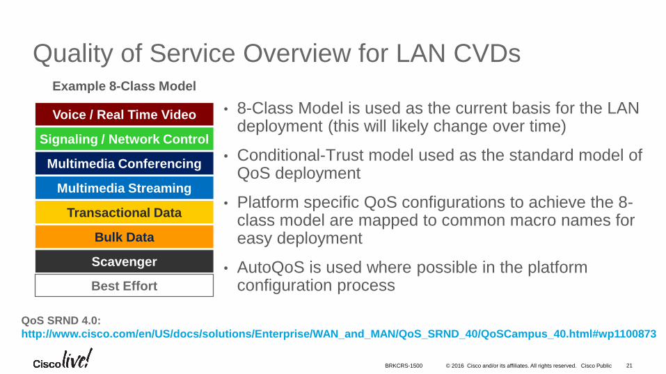
Quality of Service Overview for LAN CVDs
• 8-Class Model is used as the current basis for the LAN deployment (this will likely change over time)
• Conditional-Trust model used as the standard model of QoS deployment
• Platform specific QoS configurations to achieve the 8-class model are mapped to common macro names for easy deployment
• AutoQoS is used where possible in the platform configuration process
Example 8-Class Model
QoS SRND 4.0:
http://www.cisco.com/en/US/docs/solutions/Enterprise/WAN_and_MAN/QoS_SRND_40/QoSCampus_40.html#wp1100873
Voice / Real Time Video
Transactional Data
Multimedia Conferencing
Bulk Data
Scavenger
Best Effort
Multimedia Streaming
Signaling / Network Control
BRKCRS-1500
© 2016 Cisco and/or its affiliates. All rights reserved. Cisco Public 22
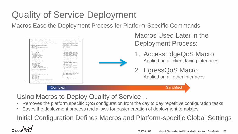
Quality of Service DeploymentMacros Ease the Deployment Process for Platform-Specific Commands
Macros Used Later in the
Deployment Process:
1. AccessEdgeQoS MacroApplied on all client facing interfaces
2. EgressQoS MacroApplied on all other interfaces
Using Macros to Deploy Quality of Service…• Removes the platform specific QoS configuration from the day to day repetitive configuration tasks
• Eases the deployment process and allows for easier creation of deployment templates
Complex Simplified
Initial Configuration Defines Macros and Platform-specific Global Settings
BRKCRS-1500
• Introduction to the Campus Wired LAN Deployment CVD
• Access Layer Deployment
• Attributes and platform choices
• Platform Specific
• Global Options
• Client facing interfaces
• Uplinks to Distribution Layer
• Distribution Layer Deployment
• Core Layer Deployment
• Conclusion
Agenda
© 2016 Cisco and/or its affiliates. All rights reserved. Cisco Public 24
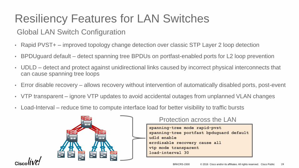
Resiliency Features for LAN Switches
• Rapid PVST+ – improved topology change detection over classic STP Layer 2 loop detection
• BPDUguard default – detect spanning tree BPDUs on portfast-enabled ports for L2 loop prevention
• UDLD – detect and protect against unidirectional links caused by incorrect physical interconnects that can cause spanning tree loops
• Error disable recovery – allows recovery without intervention of automatically disabled ports, post-event
• VTP transparent – ignore VTP updates to avoid accidental outages from unplanned VLAN changes
• Load-Interval – reduce time to compute interface load for better visibility to traffic bursts
Global LAN Switch Configuration
spanning-tree mode rapid-pvst
spanning-tree portfast bpduguard default
udld enable
errdisable recovery cause all
vtp mode transparent
load-interval 30
Protection across the LAN
BRKCRS-1500
© 2016 Cisco and/or its affiliates. All rights reserved. Cisco Public 25
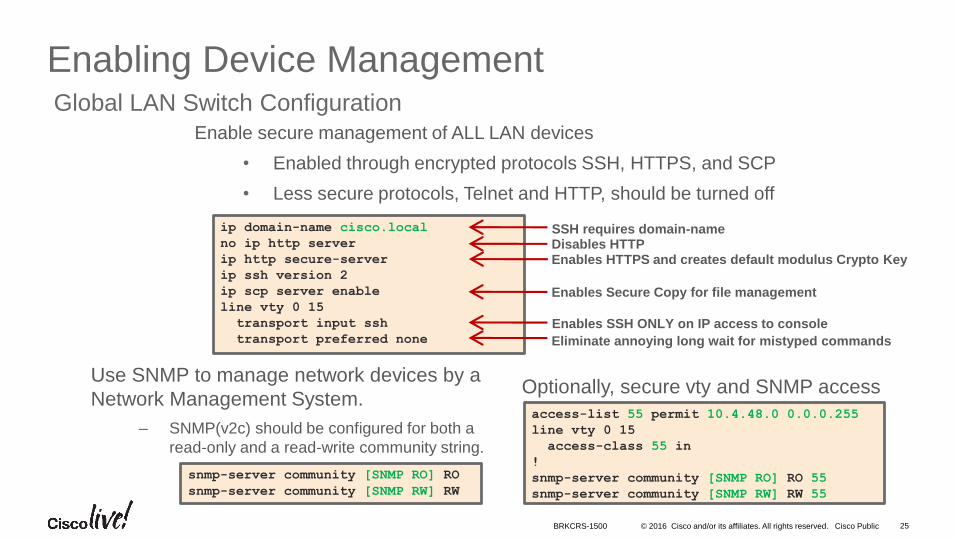
Enabling Device ManagementGlobal LAN Switch Configuration
snmp-server community [SNMP RO] RO
snmp-server community [SNMP RW] RW
ip domain-name cisco.local
no ip http server
ip http secure-server
ip ssh version 2
ip scp server enable
line vty 0 15
transport input ssh
transport preferred none
SSH requires domain-nameDisables HTTP
Enables SSH ONLY on IP access to console
Enables HTTPS and creates default modulus Crypto Key
Eliminate annoying long wait for mistyped commands
access-list 55 permit 10.4.48.0 0.0.0.255
line vty 0 15
access-class 55 in
!
snmp-server community [SNMP RO] RO 55
snmp-server community [SNMP RW] RW 55
Optionally, secure vty and SNMP accessUse SNMP to manage network devices by a
Network Management System.
‒ SNMP(v2c) should be configured for both a
read-only and a read-write community string.
Enable secure management of ALL LAN devices
• Enabled through encrypted protocols SSH, HTTPS, and SCP
• Less secure protocols, Telnet and HTTP, should be turned off
Enables Secure Copy for file management
BRKCRS-1500
© 2016 Cisco and/or its affiliates. All rights reserved. Cisco Public 26
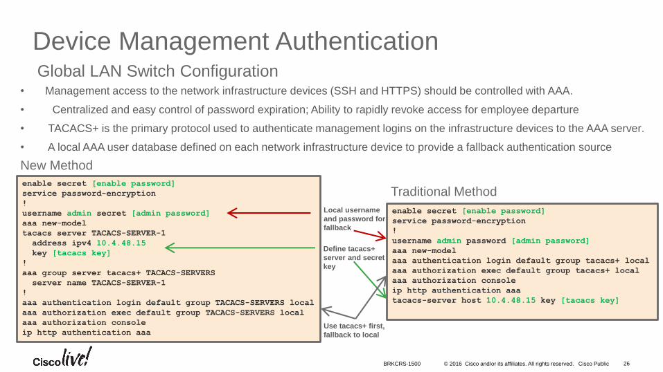
Device Management AuthenticationGlobal LAN Switch Configuration
enable secret [enable password]
service password-encryption
!
username admin password [admin password]
aaa new-model
aaa authentication login default group tacacs+ local
aaa authorization exec default group tacacs+ local
aaa authorization console
ip http authentication aaa
tacacs-server host 10.4.48.15 key [tacacs key]
Local username
and password for
fallback
Use tacacs+ first,
fallback to local
Define tacacs+
server and secret
key
enable secret [enable password]
service password-encryption
!
username admin secret [admin password]
aaa new-model
tacacs server TACACS-SERVER-1
address ipv4 10.4.48.15
key [tacacs key]
!
aaa group server tacacs+ TACACS-SERVERS
server name TACACS-SERVER-1
!
aaa authentication login default group TACACS-SERVERS local
aaa authorization exec default group TACACS-SERVERS local
aaa authorization console
ip http authentication aaa
New Method
Traditional Method
• Management access to the network infrastructure devices (SSH and HTTPS) should be controlled with AAA.
• Centralized and easy control of password expiration; Ability to rapidly revoke access for employee departure
• TACACS+ is the primary protocol used to authenticate management logins on the infrastructure devices to the AAA server.
• A local AAA user database defined on each network infrastructure device to provide a fallback authentication source
BRKCRS-1500
© 2016 Cisco and/or its affiliates. All rights reserved. Cisco Public 27
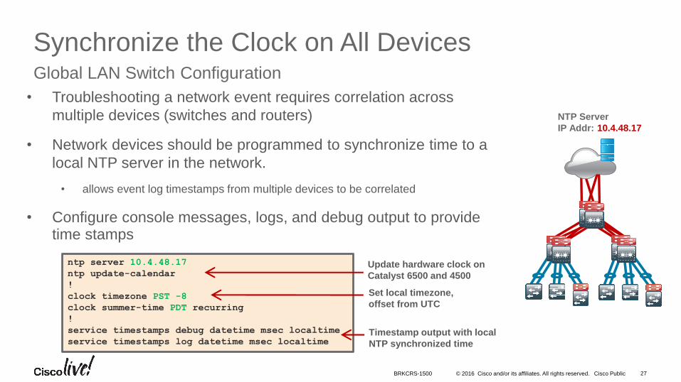
Synchronize the Clock on All DevicesGlobal LAN Switch Configuration
NTP Server
IP Addr: 10.4.48.17
ntp server 10.4.48.17
ntp update-calendar
!
clock timezone PST -8
clock summer-time PDT recurring
!
service timestamps debug datetime msec localtime
service timestamps log datetime msec localtimeTimestamp output with local
NTP synchronized time
Set local timezone,
offset from UTC
Update hardware clock on
Catalyst 6500 and 4500
• Troubleshooting a network event requires correlation across
multiple devices (switches and routers)
• Network devices should be programmed to synchronize time to a
local NTP server in the network.
• allows event log timestamps from multiple devices to be correlated
• Configure console messages, logs, and debug output to provide time stamps
BRKCRS-1500
© 2016 Cisco and/or its affiliates. All rights reserved. Cisco Public
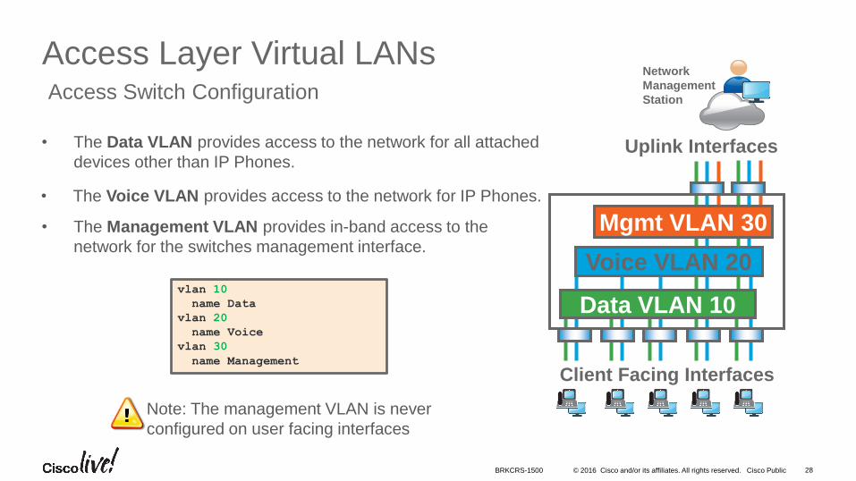
• The Data VLAN provides access to the network for all attached
devices other than IP Phones.
• The Management VLAN provides in-band access to the
network for the switches management interface.
• The Voice VLAN provides access to the network for IP Phones.
28
Access Layer Virtual LANsAccess Switch Configuration
vlan 10
name Data
vlan 20
name Voice
vlan 30
name Management
Note: The management VLAN is never
configured on user facing interfaces
Uplink Interfaces
Mgmt VLAN 30
Data VLAN 10
Voice VLAN 20
Client Facing Interfaces
Network
Management
Station
BRKCRS-1500
© 2016 Cisco and/or its affiliates. All rights reserved. Cisco Public 29
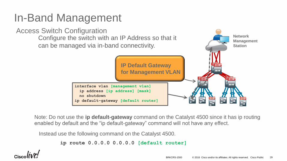
In-Band ManagementAccess Switch Configuration
Network
Management
Station
Note: Do not use the ip default-gateway command on the Catalyst 4500 since it has ip routing enabled by default and the “ip default-gateway” command will not have any effect.
Instead use the following command on the Catalyst 4500.
ip route 0.0.0.0 0.0.0.0 [default router]
interface vlan [management vlan]
ip address [ip address] [mask]
no shutdown
ip default-gateway [default router]
IP Default Gateway
for Management VLAN
Configure the switch with an IP Address so that it
can be managed via in-band connectivity.
BRKCRS-1500
• Introduction to the Campus Wired LAN Deployment CVD
• Access Layer Deployment
• Attributes and platform choices
• Platform Specific
• Global Options
• Client facing interfaces
• Uplinks to Distribution Layer
• Distribution Layer Deployment
• Core Layer Deployment
• Conclusion
Agenda
© 2016 Cisco and/or its affiliates. All rights reserved. Cisco Public
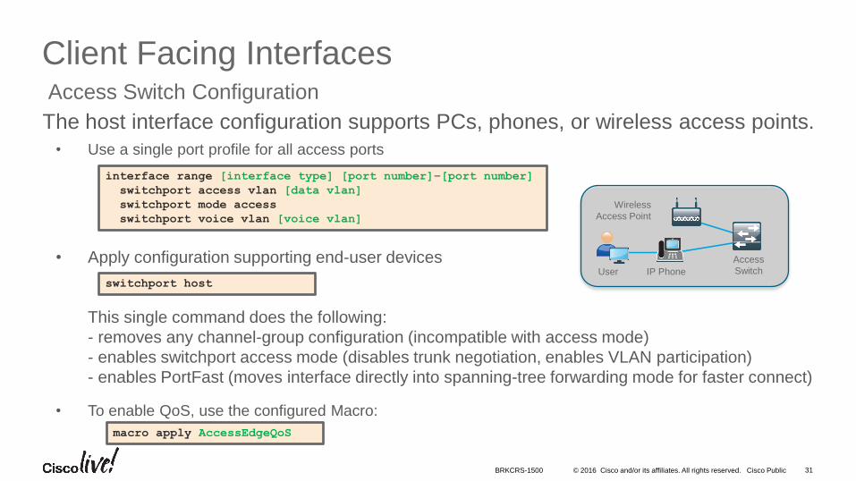
• Use a single port profile for all access ports
• Apply configuration supporting end-user devices
This single command does the following:
- removes any channel-group configuration (incompatible with access mode)
- enables switchport access mode (disables trunk negotiation, enables VLAN participation)
- enables PortFast (moves interface directly into spanning-tree forwarding mode for faster connect)
• To enable QoS, use the configured Macro:
31
Client Facing InterfacesAccess Switch Configuration
interface range [interface type] [port number]–[port number]
switchport access vlan [data vlan]
switchport mode access
switchport voice vlan [voice vlan]
switchport host
macro apply AccessEdgeQoS
Wireless
Access Point
User IP Phone
Access
Switch
The host interface configuration supports PCs, phones, or wireless access points.
BRKCRS-1500
© 2016 Cisco and/or its affiliates. All rights reserved. Cisco Public 32
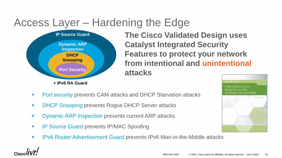
Access Layer – Hardening the EdgeIP Source Guard
Dynamic ARPInspection
DHCPSnooping
Port Security
The Cisco Validated Design uses
Catalyst Integrated Security
Features to protect your network
from intentional and unintentional
attacks
Port security prevents CAM attacks and DHCP Starvation attacks
DHCP Snooping prevents Rogue DHCP Server attacks
Dynamic ARP Inspection prevents current ARP attacks
IP Source Guard prevents IP/MAC Spoofing
IPv6 Router Advertisement Guard prevents IPv6 Man-in-the-Middle attacks
+ IPv6 RA Guard
BRKCRS-1500
© 2016 Cisco and/or its affiliates. All rights reserved. Cisco Public 33
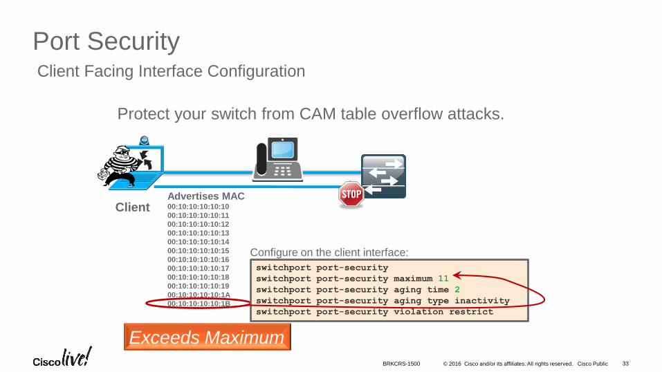
Port SecurityClient Facing Interface Configuration
ClientAdvertises MAC00:10:10:10:10:10
00:10:10:10:10:11
00:10:10:10:10:12
00:10:10:10:10:13
00:10:10:10:10:14
00:10:10:10:10:15
00:10:10:10:10:16
00:10:10:10:10:17
00:10:10:10:10:18
00:10:10:10:10:19
00:10:10:10:10:1A
00:10:10:10:10:1B
Exceeds Maximum
switchport port-security
switchport port-security maximum 11
switchport port-security aging time 2
switchport port-security aging type inactivity
switchport port-security violation restrict
Configure on the client interface:
Protect your switch from CAM table overflow attacks.
BRKCRS-1500
© 2016 Cisco and/or its affiliates. All rights reserved. Cisco Public 34
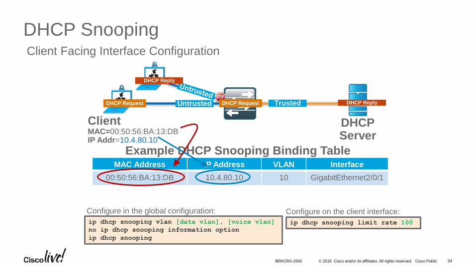
DHCP SnoopingClient Facing Interface Configuration
Configure in the global configuration:
Example DHCP Snooping Binding TableMAC Address IP Address VLAN Interface
00:50:56:BA:13:DB 10.4.80.10 10 GigabitEthernet2/0/1
ClientMAC=00:50:56:BA:13:DBIP Addr=10.4.80.10
TrustedUntrustedDHCP Request
DHCPServer
DHCP Request
DHCP Reply
DHCP Reply
ip dhcp snooping vlan [data vlan], [voice vlan]
no ip dhcp snooping information option
ip dhcp snooping
ip dhcp snooping limit rate 100
Configure on the client interface:
DHCP Request
BRKCRS-1500
© 2016 Cisco and/or its affiliates. All rights reserved. Cisco Public 35
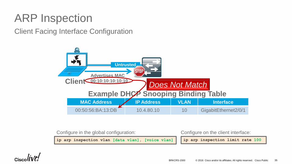
ARP InspectionClient Facing Interface Configuration
Client
Untrusted
Example DHCP Snooping Binding TableMAC Address IP Address VLAN Interface
00:50:56:BA:13:DB 10.4.80.10 10 GigabitEthernet2/0/1
Advertises MAC
00:10:10:10:10:10Does Not Match
Configure in the global configuration:
ip arp inspection vlan [data vlan], [voice vlan] ip arp inspection limit rate 100
Configure on the client interface:
BRKCRS-1500
© 2016 Cisco and/or its affiliates. All rights reserved. Cisco Public 36
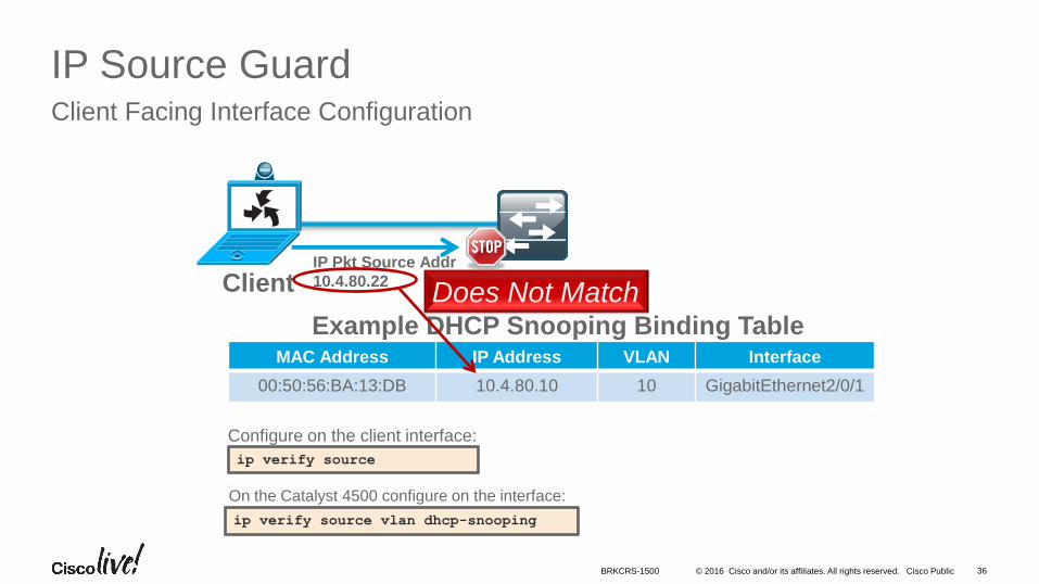
IP Source GuardClient Facing Interface Configuration
Client
Example DHCP Snooping Binding TableMAC Address IP Address VLAN Interface
00:50:56:BA:13:DB 10.4.80.10 10 GigabitEthernet2/0/1
IP Pkt Source Addr
10.4.80.22Does Not Match
On the Catalyst 4500 configure on the interface:
ip verify source vlan dhcp-snooping
ip verify source
Configure on the client interface:
BRKCRS-1500
© 2016 Cisco and/or its affiliates. All rights reserved. Cisco Public 37
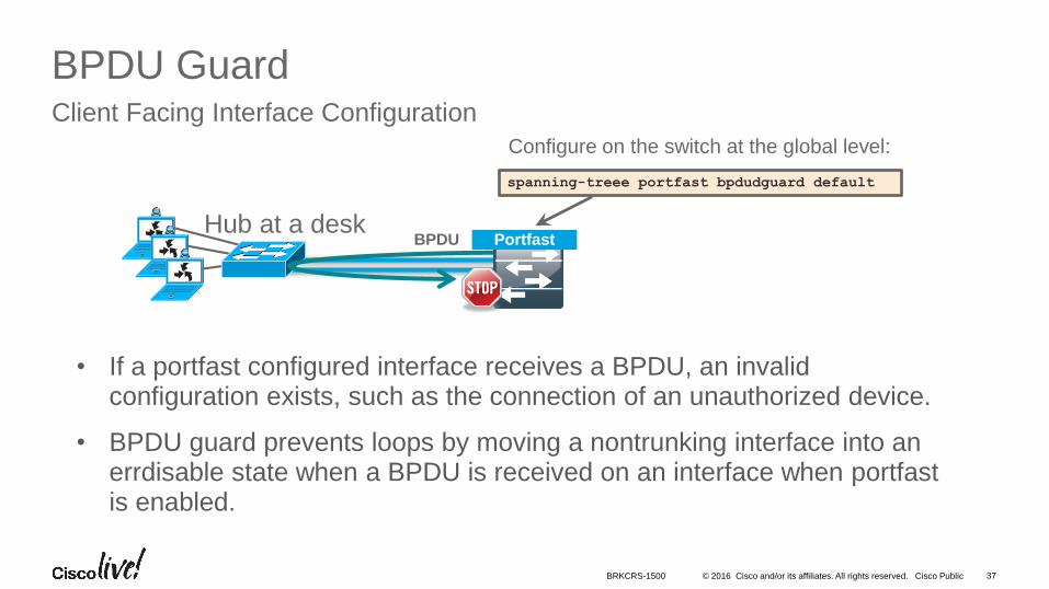
BPDU GuardClient Facing Interface Configuration
• If a portfast configured interface receives a BPDU, an invalid configuration exists, such as the connection of an unauthorized device.
• BPDU guard prevents loops by moving a nontrunking interface into an errdisable state when a BPDU is received on an interface when portfast is enabled.
BPDUHub at a desk
spanning-treee portfast bpdudguard default
Configure on the switch at the global level:
Portfast
BRKCRS-1500
© 2016 Cisco and/or its affiliates. All rights reserved. Cisco Public 38
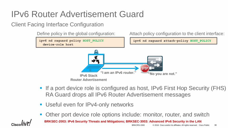
IPv6 Router Advertisement GuardClient Facing Interface Configuration
If a port device role is configured as host, IPv6 First Hop Security (FHS) RA Guard drops all IPv6 Router Advertisement messages
Useful even for IPv4-only networks
Other port device role options include: monitor, router, and switch
“I am an IPv6 router.” “No you are not.”
Define policy in the global configuration:
ipv6 nd raguard policy HOST_POLICY
device-role host
ipv6 nd raguard attach-policy HOST_POLICY
Attach policy configuration to the client interface:
IPv6 Stack
Router Advertisement
BRKSEC-2003: IPv6 Security Threats and Mitigations; BRKSEC-3003: Advanced IPv6 Security in the LANBRKCRS-1500

• Introduction to the Campus Wired LAN Deployment CVD
• Access Layer Deployment
• Attributes and platform choices
• Platform Specific
• Global Options
• Client facing interfaces
• Uplinks to Distribution Layer
• Distribution Layer Deployment
• Core Layer Deployment
• Conclusion
Agenda
© 2016 Cisco and/or its affiliates. All rights reserved. Cisco Public 40
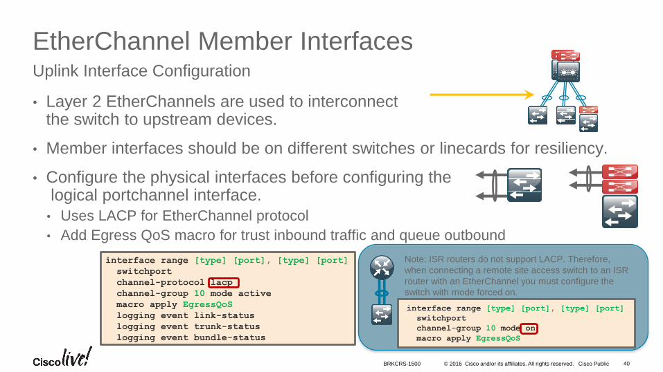
EtherChannel Member Interfaces
• Layer 2 EtherChannels are used to interconnectthe switch to upstream devices.
• Member interfaces should be on different switches or linecards for resiliency.
• Configure the physical interfaces before configuring thelogical portchannel interface.
• Uses LACP for EtherChannel protocol
• Add Egress QoS macro for trust inbound traffic and queue outbound
Uplink Interface Configuration
interface range [type] [port], [type] [port]
switchport
channel-protocol lacp
channel-group 10 mode active
macro apply EgressQoS
logging event link-status
logging event trunk-status
logging event bundle-status
Note: ISR routers do not support LACP. Therefore,
when connecting a remote site access switch to an ISR
router with an EtherChannel you must configure the
switch with mode forced on.
interface range [type] [port], [type] [port]
switchport
channel-group 10 mode on
macro apply EgressQoS
BRKCRS-1500
© 2016 Cisco and/or its affiliates. All rights reserved. Cisco Public 41
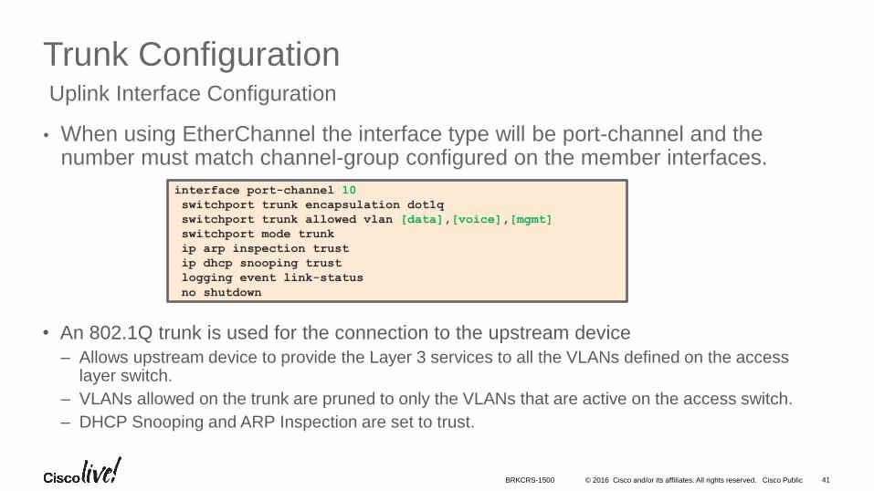
Trunk Configuration
• When using EtherChannel the interface type will be port-channel and the number must match channel-group configured on the member interfaces.
Uplink Interface Configuration
interface port-channel 10
switchport trunk encapsulation dot1q
switchport trunk allowed vlan [data],[voice],[mgmt]
switchport mode trunk
ip arp inspection trust
ip dhcp snooping trust
logging event link-status
no shutdown
• An 802.1Q trunk is used for the connection to the upstream device
– Allows upstream device to provide the Layer 3 services to all the VLANs defined on the access layer switch.
– VLANs allowed on the trunk are pruned to only the VLANs that are active on the access switch.
– DHCP Snooping and ARP Inspection are set to trust.
BRKCRS-1500
• Introduction to the Campus Wired LAN Deployment CVD
• Access Layer Deployment
• Distribution Layer Deployment
• Attributes and platform choices
• Platform Specific
• Global Options
• Connectivity to Access and Core Layers
• Core Layer Deployment
• Conclusion
Agenda
© 2016 Cisco and/or its affiliates. All rights reserved. Cisco Public
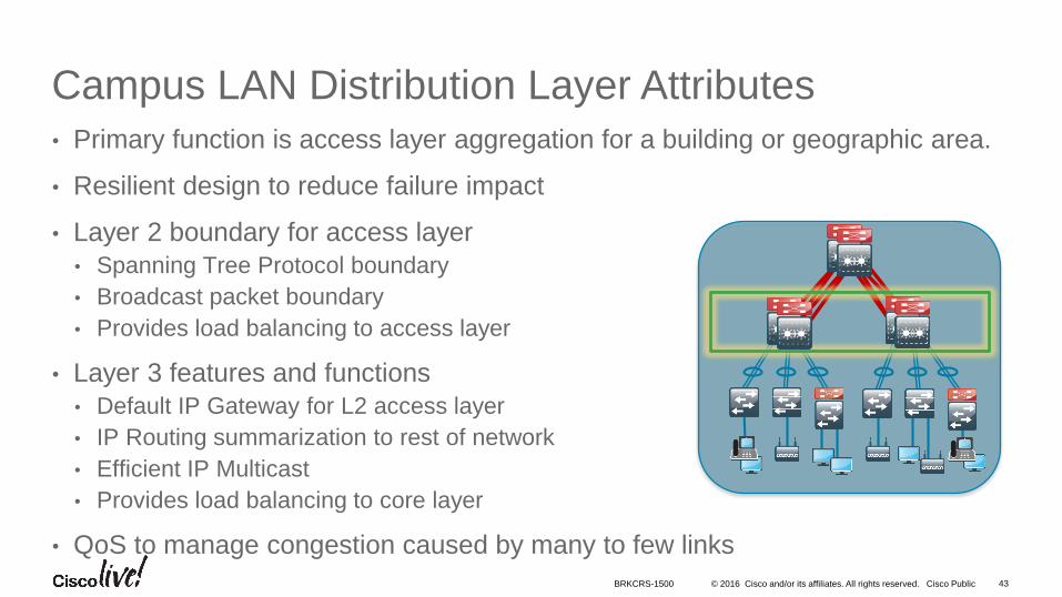
Campus LAN Distribution Layer Attributes
• Primary function is access layer aggregation for a building or geographic area.
• Resilient design to reduce failure impact
• Layer 2 boundary for access layer
• Spanning Tree Protocol boundary
• Broadcast packet boundary
• Provides load balancing to access layer
• Layer 3 features and functions
• Default IP Gateway for L2 access layer
• IP Routing summarization to rest of network
• Efficient IP Multicast
• Provides load balancing to core layer
• QoS to manage congestion caused by many to few links
43BRKCRS-1500
© 2016 Cisco and/or its affiliates. All rights reserved. Cisco Public 44
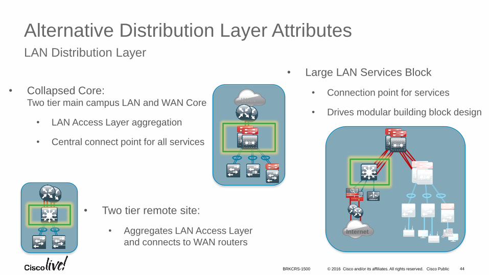
Alternative Distribution Layer AttributesLAN Distribution Layer
• Large LAN Services Block
• Connection point for services
• Drives modular building block design
• Two tier remote site:
• Aggregates LAN Access Layer
and connects to WAN routers
Internet
WAN
• Collapsed Core: Two tier main campus LAN and WAN Core
• LAN Access Layer aggregation
• Central connect point for all services
BRKCRS-1500
© 2016 Cisco and/or its affiliates. All rights reserved. Cisco Public 45
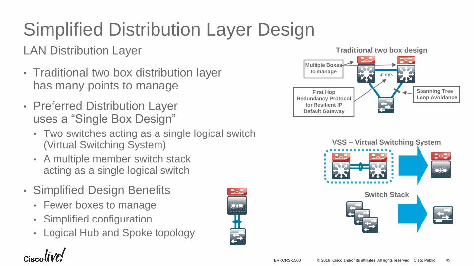
Simplified Distribution Layer Design
• Traditional two box distribution layer has many points to manage
• Preferred Distribution Layer uses a “Single Box Design”
• Two switches acting as a single logical switch(Virtual Switching System)
• A multiple member switch stack acting as a single logical switch
• Simplified Design Benefits
• Fewer boxes to manage
• Simplified configuration
• Logical Hub and Spoke topology
LAN Distribution Layer Traditional two box design
-FHRP-
Spanning Tree
Loop Avoidance
Multiple Boxes
to manage
First Hop
Redundancy Protocol
for Resilient IP
Default Gateway
VSS – Virtual Switching System
Switch Stack
BRKCRS-1500
© 2016 Cisco and/or its affiliates. All rights reserved. Cisco Public 46
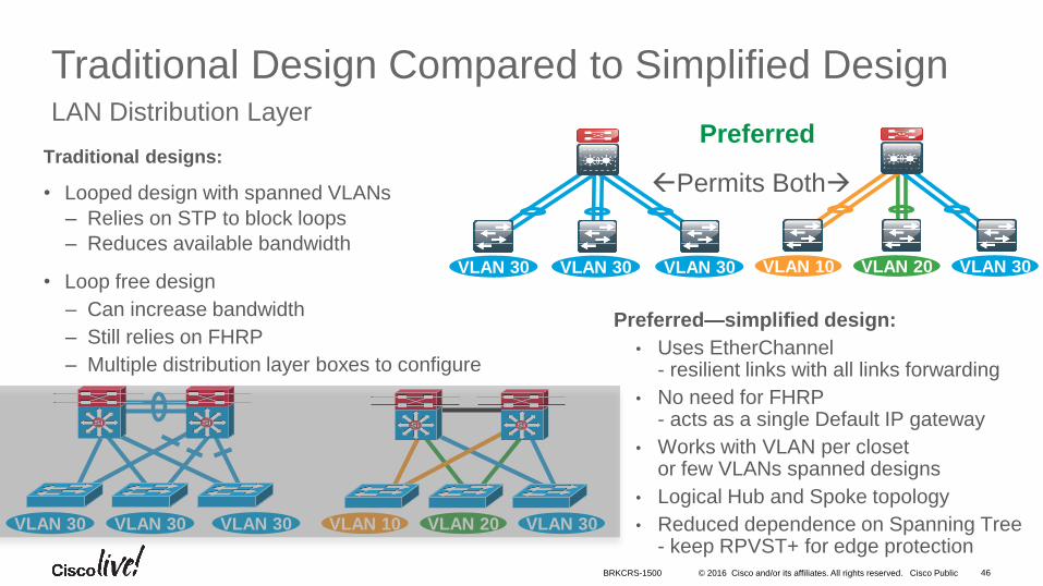
Traditional Design Compared to Simplified DesignLAN Distribution Layer
Preferred—simplified design:
• Uses EtherChannel- resilient links with all links forwarding
• No need for FHRP- acts as a single Default IP gateway
• Works with VLAN per closet or few VLANs spanned designs
• Logical Hub and Spoke topology
• Reduced dependence on Spanning Tree- keep RPVST+ for edge protection
SiSi SiSi
VLAN 30 VLAN 30 VLAN 30
SiSi SiSi
VLAN 10 VLAN 20 VLAN 30
VLAN 30 VLAN 30 VLAN 30 VLAN 10 VLAN 20 VLAN 30
Permits BothTraditional designs:
• Looped design with spanned VLANs
– Relies on STP to block loops
– Reduces available bandwidth
• Loop free design
– Can increase bandwidth
– Still relies on FHRP
– Multiple distribution layer boxes to configure
Preferred
BRKCRS-1500
© 2016 Cisco and/or its affiliates. All rights reserved. Cisco Public
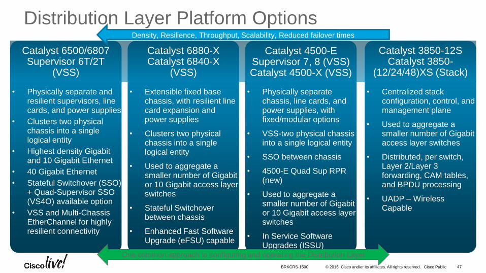
• Physically separate chassis, line cards, and power supplies, with fixed/modular options
• VSS-two physical chassis into a single logical entity
• SSO between chassis
• 4500-E Quad Sup RPR (new)
• Used to aggregate asmaller number of Gigabit or 10 Gigabit access layer switches
• In Service Software Upgrades (ISSU)
• Physically separate and resilient supervisors, line cards, and power supplies
• Clusters two physical chassis into a single logical entity
• Highest density Gigabit and 10 Gigabit Ethernet
• 40 Gigabit Ethernet
• Stateful Switchover (SSO) + Quad-Supervisor SSO (VS4O) available option
• VSS and Multi-Chassis EtherChannel for highly resilient connectivity
• Centralized stack configuration, control, and management plane
• Used to aggregate a smaller number of Gigabit access layer switches
• Distributed, per switch, Layer 2/Layer 3 forwarding, CAM tables, and BPDU processing
• UADP – Wireless Capable
• Extensible fixed base chassis, with resilient line card expansion and power supplies
• Clusters two physical chassis into a single logical entity
• Used to aggregate a smaller number of Gigabit or 10 Gigabit access layer switches
• Stateful Switchover between chassis
• Enhanced Fast Software Upgrade (eFSU) capable
47BRKCRS-1500
Distribution Layer Platform Options
One common approach to configuring and operating the Distribution Layer
Catalyst 4500-E Supervisor 7, 8 (VSS)Catalyst 4500-X (VSS)
Catalyst 6500/6807 Supervisor 6T/2T
(VSS)
Catalyst 3850-12SCatalyst 3850-
(12/24/48)XS (Stack)
Catalyst 6880-XCatalyst 6840-X
(VSS)
Density, Resilience, Throughput, Scalability, Reduced failover times
• Introduction to the Campus Wired LAN Deployment CVD
• Access Layer Deployment
• Distribution Layer Deployment
• Attributes and platform choices
• Platform Specific
• Global Options
• Connectivity to Access and Core Layers
• Core Layer Deployment
• Conclusion
Agenda
© 2016 Cisco and/or its affiliates. All rights reserved. Cisco Public 49
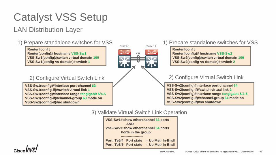
Catalyst VSS SetupLAN Distribution Layer
1) Prepare standalone switches for VSS
2) Configure Virtual Switch Link
VSS-Sw1# show etherchannel 63 ports
AND
VSS-Sw2# show etherchannel 64 ports
Ports in the group:
-------------------
Port: Te5/4 Port state = Up Mstr In-Bndl
Port: Te5/5 Port state = Up Mstr In-Bndl
Switch 1 Switch 21) Prepare standalone switches for VSS
2) Configure Virtual Switch Link
3) Validate Virtual Switch Link Operation
Router#conf t
Router(config)# hostname VSS-Sw1
VSS-Sw1(config)#switch virtual domain 100
VSS-Sw1(config-vs-domain)# switch 1
Router#conf t
Router#config)# hostname VSS-Sw2
VSS-Sw2(config)#switch virtual domain 100
VSS-Sw2(config-vs-domain)# switch 2
VSL
VSS-Sw1(config)#interface port-channel 63
VSS-Sw1(config-if)#switch virtual link 1
VSS-Sw1(config)#interface range tengigabit 5/4-5
VSS-Sw1(config-if)#channel-group 63 mode on
VSS-Sw1(config-if)#no shutdown
VSS-Sw2(config)#interface port-channel 64
VSS-Sw2(config-if)#switch virtual link 2
VSS-Sw2(config)#interface range tengigabit 5/4-5
VSS-Sw2(config-if)#channel-group 64 mode on
VSS-Sw2(config-if)#no shutdown
BRKCRS-1500
© 2016 Cisco and/or its affiliates. All rights reserved. Cisco Public 50
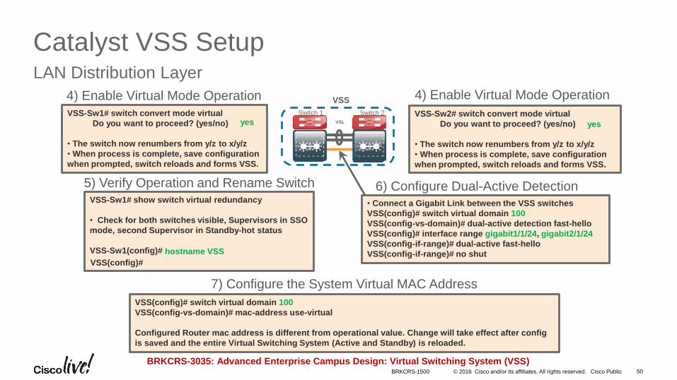
Catalyst VSS SetupLAN Distribution Layer
VSS-Sw1# show switch virtual redundancy
• Check for both switches visible, Supervisors in SSO
mode, second Supervisor in Standby-hot status
VSS-Sw1(config)#
4) Enable Virtual Mode Operation
5) Verify Operation and Rename Switch
VSS-Sw1# switch convert mode virtual
Do you want to proceed? (yes/no)
• The switch now renumbers from y/z to x/y/z
• When process is complete, save configuration
when prompted, switch reloads and forms VSS.
6) Configure Dual-Active Detection
4) Enable Virtual Mode Operation
VSS-Sw2# switch convert mode virtual
Do you want to proceed? (yes/no)
• The switch now renumbers from y/z to x/y/z
• When process is complete, save configuration
when prompted, switch reloads and forms VSS.
*Feb 25 14:28:39.294: %VSDA-SW2_SPSTBY-5-LINK_UP: Interface Gi2/1/24 is now dual-active detection capable
*Feb 25 14:28:39.323: %VSDA-SW1_SP-5-LINK_UP: Interface Gi1/1/24 is now dual-active detection capable
7) Configure the System Virtual MAC Address
VSL
VSS
Switch 1 Switch 2
BRKCRS-3035: Advanced Enterprise Campus Design: Virtual Switching System (VSS)
VSS(config)# switch virtual domain 100
VSS(config-vs-domain)# mac-address use-virtual
Configured Router mac address is different from operational value. Change will take effect after config
is saved and the entire Virtual Switching System (Active and Standby) is reloaded.
• Connect a Gigabit Link between the VSS switches
VSS(config)# switch virtual domain 100
VSS(config-vs-domain)# dual-active detection fast-hello
VSS(config)# interface range gigabit1/1/24, gigabit2/1/24
VSS(config-if-range)# dual-active fast-hello
VSS(config-if-range)# no shuthostname VSS
VSS(config)#
yes yes
BRKCRS-1500
© 2016 Cisco and/or its affiliates. All rights reserved. Cisco Public 51
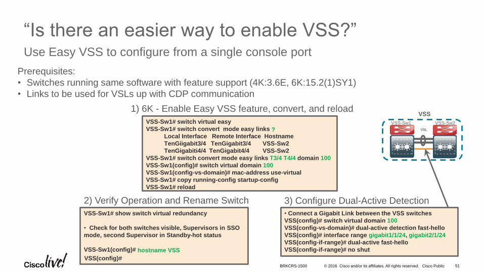
“Is there an easier way to enable VSS?”Use Easy VSS to configure from a single console port
VSS-Sw1# show switch virtual redundancy
• Check for both switches visible, Supervisors in SSO
mode, second Supervisor in Standby-hot status
VSS-Sw1(config)#
1) 6K - Enable Easy VSS feature, convert, and reload
2) Verify Operation and Rename Switch
VSS-Sw1# switch virtual easy
VSS-Sw1# switch convert mode easy links
Local Interface Remote Interface Hostname
TenGiigabit3/4 TenGigabit3/4 VSS-Sw2
TenGigabiti4/4 TenGigabit4/4 VSS-Sw2
VSS-Sw1# switch convert mode easy links T3/4 T4/4 domain 100
VSS-Sw1(config)# switch virtual domain 100
VSS-Sw1(config-vs-domain)# mac-address use-virtual
VSS-Sw1# copy running-config startup-config
VSS-Sw1# reload
3) Configure Dual-Active Detection
VSL
VSS
VSS-Sw1 VSS-Sw2
• Connect a Gigabit Link between the VSS switches
VSS(config)# switch virtual domain 100
VSS(config-vs-domain)# dual-active detection fast-hello
VSS(config)# interface range gigabit1/1/24, gigabit2/1/24
VSS(config-if-range)# dual-active fast-hello
VSS(config-if-range)# no shuthostname VSS
VSS(config)#
?
Prerequisites:
• Switches running same software with feature support (4K:3.6E, 6K:15.2(1)SY1)
• Links to be used for VSLs up with CDP communication
BRKCRS-1500
• Introduction to the Campus Wired LAN Deployment CVD
• Access Layer Deployment
• Distribution Layer Deployment
• Attributes and platform choices
• Platform Specific
• Global Options
• Connectivity to Access and Core Layers
• Core Layer Deployment
• Conclusion
Agenda
© 2016 Cisco and/or its affiliates. All rights reserved. Cisco Public 53
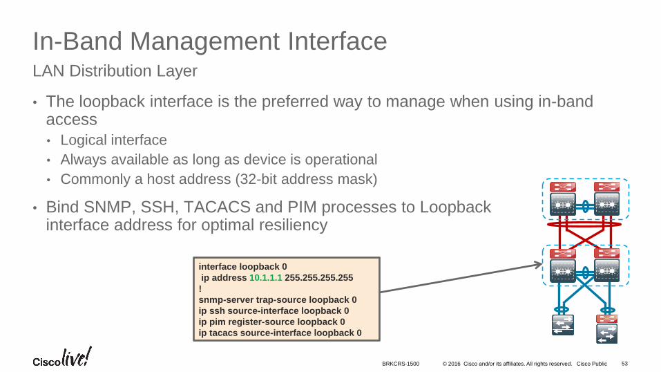
In-Band Management Interface
• The loopback interface is the preferred way to manage when using in-band access
• Logical interface
• Always available as long as device is operational
• Commonly a host address (32-bit address mask)
• Bind SNMP, SSH, TACACS and PIM processes to Loopback interface address for optimal resiliency
LAN Distribution Layer
interface loopback 0
ip address 10.1.1.1 255.255.255.255
!
snmp-server trap-source loopback 0
ip ssh source-interface loopback 0
ip pim register-source loopback 0
ip tacacs source-interface loopback 0
BRKCRS-1500
© 2016 Cisco and/or its affiliates. All rights reserved. Cisco Public 54
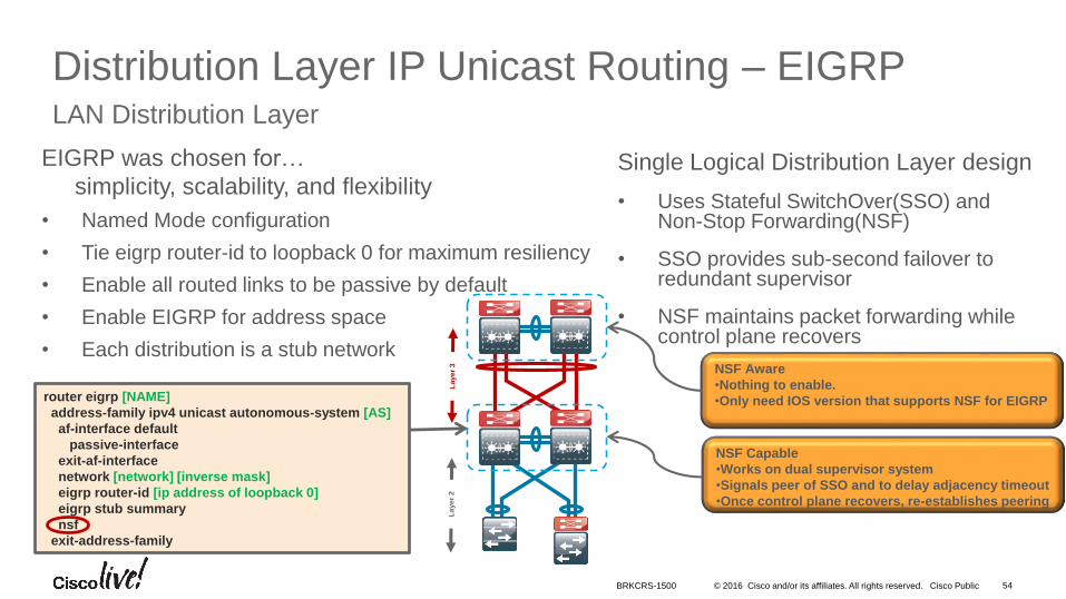
Distribution Layer IP Unicast Routing – EIGRPLAN Distribution Layer
router eigrp [NAME]
address-family ipv4 unicast autonomous-system [AS]
af-interface default
passive-interface
exit-af-interface
network [network] [inverse mask]
eigrp router-id [ip address of loopback 0]
eigrp stub summary
nsf
exit-address-family
NSF Aware
•Nothing to enable.
•Only need IOS version that supports NSF for EIGRP
Single Logical Distribution Layer design
• Uses Stateful SwitchOver(SSO) and Non-Stop Forwarding(NSF)
• SSO provides sub-second failover to redundant supervisor
• NSF maintains packet forwarding while control plane recovers
EIGRP was chosen for…
simplicity, scalability, and flexibility
• Named Mode configuration
• Tie eigrp router-id to loopback 0 for maximum resiliency
• Enable all routed links to be passive by default
• Enable EIGRP for address space
• Each distribution is a stub network
Layer
2L
ayer
3NSF Capable
•Works on dual supervisor system
•Signals peer of SSO and to delay adjacency timeout
•Once control plane recovers, re-establishes peering
BRKCRS-1500
© 2016 Cisco and/or its affiliates. All rights reserved. Cisco Public 55
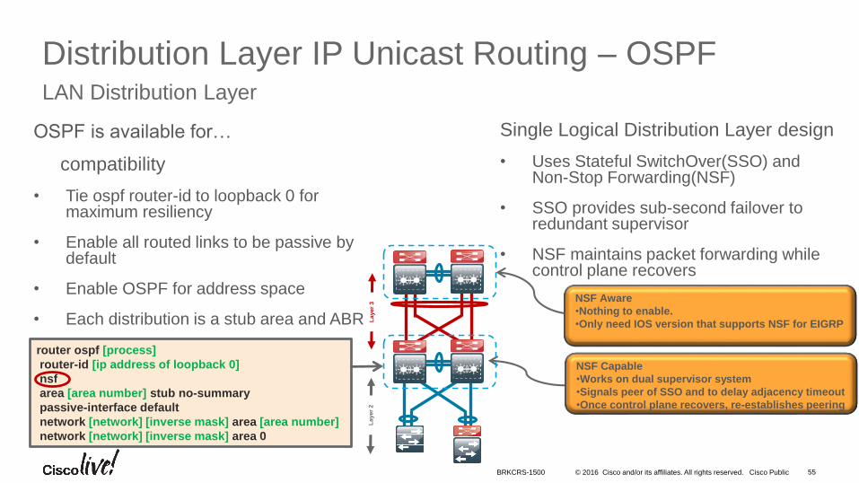
Distribution Layer IP Unicast Routing – OSPFLAN Distribution Layer
router ospf [process]
router-id [ip address of loopback 0]
nsf
area [area number] stub no-summary
passive-interface default
network [network] [inverse mask] area [area number]
network [network] [inverse mask] area 0
Single Logical Distribution Layer design
• Uses Stateful SwitchOver(SSO) and Non-Stop Forwarding(NSF)
• SSO provides sub-second failover to redundant supervisor
• NSF maintains packet forwarding while control plane recovers
OSPF is available for…
compatibility
• Tie ospf router-id to loopback 0 for maximum resiliency
• Enable all routed links to be passive by default
• Enable OSPF for address space
• Each distribution is a stub area and ABR
Layer
2L
ayer
3
NSF Aware
•Nothing to enable.
•Only need IOS version that supports NSF for EIGRP
NSF Capable
•Works on dual supervisor system
•Signals peer of SSO and to delay adjacency timeout
•Once control plane recovers, re-establishes peering
BRKCRS-1500
© 2016 Cisco and/or its affiliates. All rights reserved. Cisco Public
WAN
56
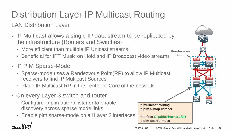
Distribution Layer IP Multicast Routing
• IP Multicast allows a single IP data stream to be replicated by the infrastructure (Routers and Switches)
• More efficient than multiple IP Unicast streams
• Beneficial for IPT Music on Hold and IP Broadcast video streams
• IP PIM Sparse-Mode
• Sparse-mode uses a Rendezvous Point(RP) to allow IP Multicast receivers to find IP Multicast Sources
• Place IP Multicast RP in the center or Core of the network
• On every Layer 3 switch and router
• Configure ip pim autorp listener to enable discovery across sparse mode links
• Enable pim sparse-mode on all Layer 3 interfaces
LAN Distribution Layer
Rendezvous
Point
ip multicast-routing
ip pim autorp listener
!
interface GigabitEthernet 1/0/1
ip pim sparse-mode
BRKCRS-1500
• Introduction to the Campus Wired LAN Deployment CVD
• Access Layer Deployment
• Distribution Layer Deployment
• Attributes and platform choices
• Platform Specific
• Global Options
• Connectivity to Access and Core Layers
• Core Layer Deployment
• Conclusion
Agenda
© 2016 Cisco and/or its affiliates. All rights reserved. Cisco Public 58
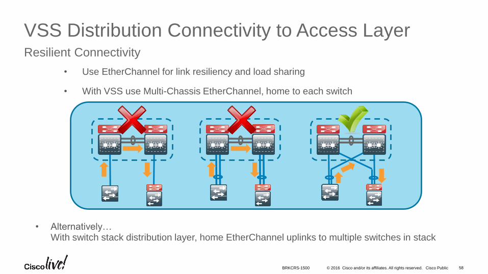
VSS Distribution Connectivity to Access LayerResilient Connectivity
• Alternatively…With switch stack distribution layer, home EtherChannel uplinks to multiple switches in stack
• Use EtherChannel for link resiliency and load sharing
• With VSS use Multi-Chassis EtherChannel, home to each switch
BRKCRS-1500
© 2016 Cisco and/or its affiliates. All rights reserved. Cisco Public 59
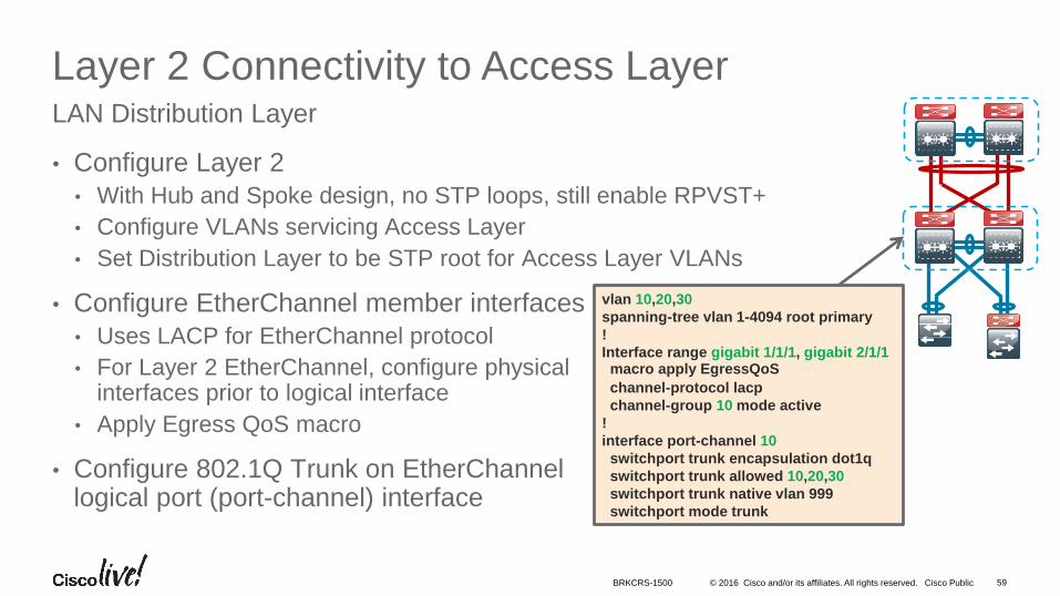
Layer 2 Connectivity to Access Layer
• Configure Layer 2
• With Hub and Spoke design, no STP loops, still enable RPVST+
• Configure VLANs servicing Access Layer
• Set Distribution Layer to be STP root for Access Layer VLANs
• Configure EtherChannel member interfaces
• Uses LACP for EtherChannel protocol
• For Layer 2 EtherChannel, configure physicalinterfaces prior to logical interface
• Apply Egress QoS macro
• Configure 802.1Q Trunk on EtherChannellogical port (port-channel) interface
LAN Distribution Layer
vlan 10,20,30
spanning-tree vlan 1-4094 root primary
!
Interface range gigabit 1/1/1, gigabit 2/1/1macro apply EgressQoS
channel-protocol lacp
channel-group 10 mode active
!
interface port-channel 10
switchport trunk encapsulation dot1q
switchport trunk allowed 10,20,30
switchport trunk native vlan 999
switchport mode trunk
BRKCRS-1500
© 2016 Cisco and/or its affiliates. All rights reserved. Cisco Public
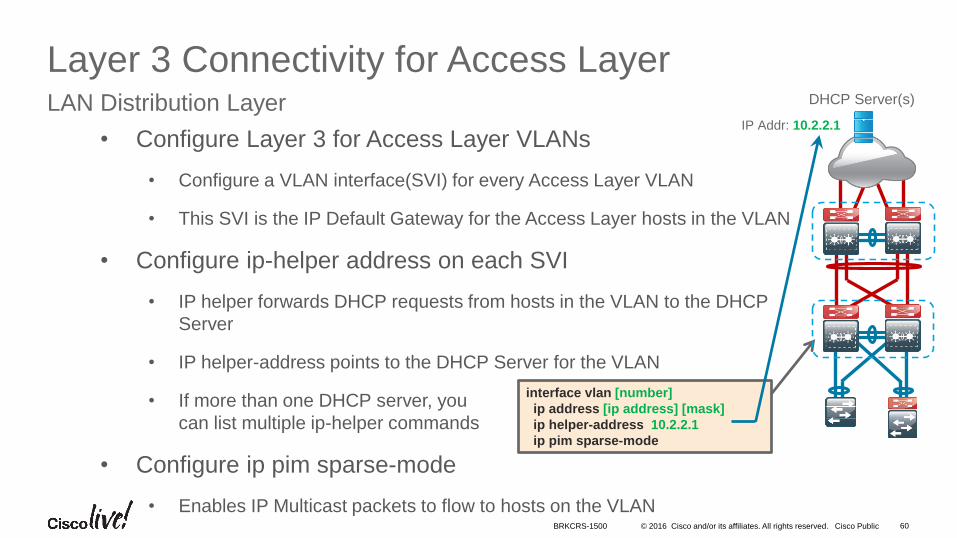
• Configure Layer 3 for Access Layer VLANs
• Configure a VLAN interface(SVI) for every Access Layer VLAN
• This SVI is the IP Default Gateway for the Access Layer hosts in the VLAN
• Configure ip-helper address on each SVI
• IP helper forwards DHCP requests from hosts in the VLAN to the DHCP
Server
• IP helper-address points to the DHCP Server for the VLAN
• If more than one DHCP server, you
can list multiple ip-helper commands
• Configure ip pim sparse-mode
• Enables IP Multicast packets to flow to hosts on the VLAN
DHCP Server(s)
60
Layer 3 Connectivity for Access LayerLAN Distribution Layer
interface vlan [number]
ip address [ip address] [mask]
ip helper-address 10.2.2.1
ip pim sparse-mode
IP Addr: 10.2.2.1
BRKCRS-1500
© 2016 Cisco and/or its affiliates. All rights reserved. Cisco Public 61
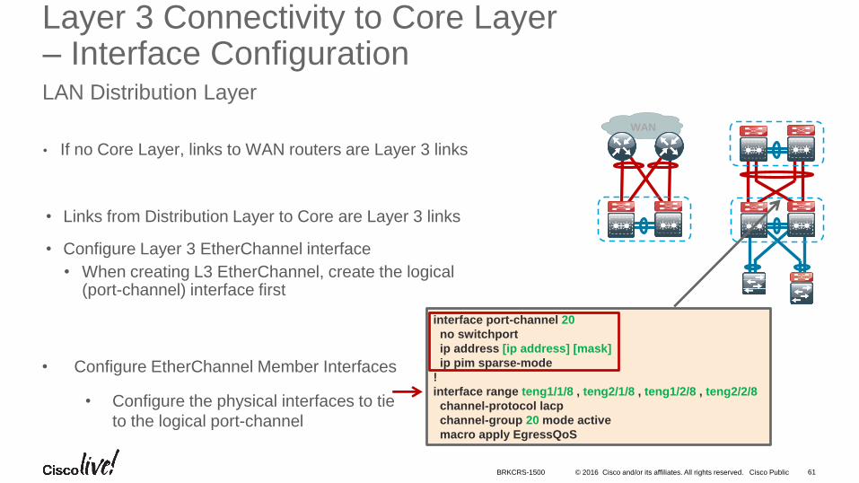
Layer 3 Connectivity to Core Layer– Interface ConfigurationLAN Distribution Layer
• If no Core Layer, links to WAN routers are Layer 3 links
• Configure EtherChannel Member Interfaces
• Configure the physical interfaces to tie
to the logical port-channel
interface port-channel 20
no switchport
ip address [ip address] [mask]
ip pim sparse-mode
!
interface range teng1/1/8 , teng2/1/8 , teng1/2/8 , teng2/2/8
channel-protocol lacp
channel-group 20 mode active
macro apply EgressQoS
• Links from Distribution Layer to Core are Layer 3 links
• Configure Layer 3 EtherChannel interface
• When creating L3 EtherChannel, create the logical (port-channel) interface first
WAN
BRKCRS-1500
© 2016 Cisco and/or its affiliates. All rights reserved. Cisco Public 62
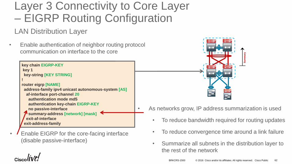
Layer 3 Connectivity to Core Layer– EIGRP Routing ConfigurationLAN Distribution Layer
• Enable authentication of neighbor routing protocol
communication on interface to the core
• Enable EIGRP for the core-facing interface
(disable passive-interface)
Su
mm
ary
key chain EIGRP-KEY
key 1
key-string [KEY STRING]
!
router eigrp [NAME]
address-family ipv4 unicast autonomous-system [AS]
af-interface port-channel 20
authentication mode md5
authentication key-chain EIGRP-KEY
no passive-interface
summary-address [network] [mask]
exit-af-interface
exit-address-family
• As networks grow, IP address summarization is used
• To reduce bandwidth required for routing updates
• To reduce convergence time around a link failure
• Summarize all subnets in the distribution layer to
the rest of the network
BRKCRS-1500
© 2016 Cisco and/or its affiliates. All rights reserved. Cisco Public
• Enable authentication of neighbor routing protocol
communication on interface to the core
63
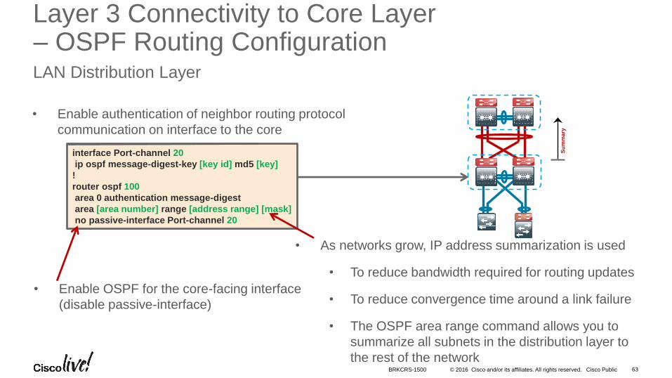
Layer 3 Connectivity to Core Layer– OSPF Routing ConfigurationLAN Distribution Layer
• Enable OSPF for the core-facing interface
(disable passive-interface)
Su
mm
ary
interface Port-channel 20
ip ospf message-digest-key [key id] md5 [key]
!
router ospf 100
area 0 authentication message-digest
area [area number] range [address range] [mask]
no passive-interface Port-channel 20
• As networks grow, IP address summarization is used
• To reduce bandwidth required for routing updates
• To reduce convergence time around a link failure
• The OSPF area range command allows you to
summarize all subnets in the distribution layer to
the rest of the networkBRKCRS-1500
• Introduction to the Campus Wired LAN Deployment CVD
• Access Layer Deployment
• Distribution Layer Deployment
• Core Layer Deployment
• Attributes and platform
• Global Options
• Conclusion
Agenda
© 2016 Cisco and/or its affiliates. All rights reserved. Cisco Public 65
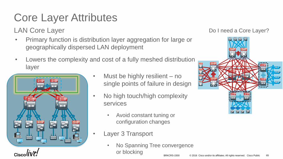
Core Layer AttributesLAN Core Layer Do I need a Core Layer?
• Must be highly resilient – no
single points of failure in design
• No high touch/high complexity
services
• Avoid constant tuning or
configuration changes
• Layer 3 Transport
• No Spanning Tree convergence
or blocking
• Primary function is distribution layer aggregation for large or
geographically dispersed LAN deployment
• Lowers the complexity and cost of a fully meshed distribution
layer
BRKCRS-1500
© 2016 Cisco and/or its affiliates. All rights reserved. Cisco Public
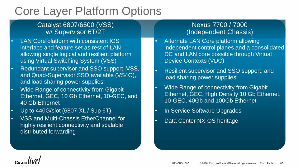
• Alternate LAN Core platform allowing independent control planes and a consolidated DC and LAN core possible through Virtual Device Contexts (VDC)
• Resilient supervisor and SSO support, and load sharing power supplies
• Wide Range of connectivity from Gigabit Ethernet, GEC, High Density 10 Gb Ethernet, 10-GEC, 40Gb and 100Gb Ethernet
• In Service Software Upgrades
• Data Center NX-OS heritage
66BRKCRS-1500
Core Layer Platform Options
• LAN Core platform with consistent IOS interface and feature set as rest of LAN allowing single logical and resilient platform using Virtual Switching System (VSS)
• Redundant supervisor and SSO support, VSS, and Quad-Supervisor SSO available (VS4O), and load sharing power supplies
• Wide Range of connectivity from Gigabit Ethernet, GEC, 10 Gb Ethernet, 10-GEC, and 40 Gb Ethernet
• Up to 440G/slot (6807-XL / Sup 6T)
• VSS and Multi-Chassis EtherChannel for highly resilient connectivity and scalable distributed forwarding
Nexus 7700 / 7000(Independent Chassis)
Catalyst 6807/6500 (VSS)w/ Supervisor 6T/2T
• Introduction to the Campus Wired LAN Deployment CVD
• Access Layer Deployment
• Distribution Layer Deployment
• Core Layer Deployment
• Attributes and platform
• Global Options
• Conclusion
Agenda
© 2016 Cisco and/or its affiliates. All rights reserved. Cisco Public 68
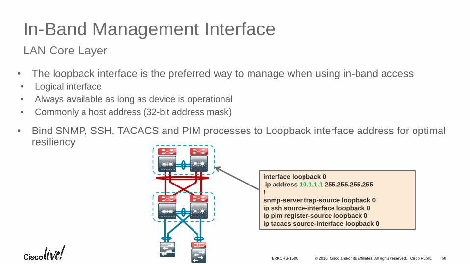
In-Band Management InterfaceLAN Core Layer
• The loopback interface is the preferred way to manage when using in-band access
• Logical interface
• Always available as long as device is operational
• Commonly a host address (32-bit address mask)
• Bind SNMP, SSH, TACACS and PIM processes to Loopback interface address for optimal resiliency
interface loopback 0
ip address 10.1.1.1 255.255.255.255
!
snmp-server trap-source loopback 0
ip ssh source-interface loopback 0
ip pim register-source loopback 0
ip tacacs source-interface loopback 0
BRKCRS-1500
© 2016 Cisco and/or its affiliates. All rights reserved. Cisco Public 69
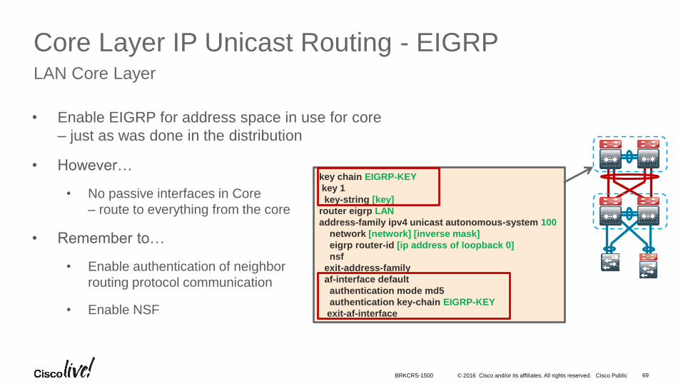
Core Layer IP Unicast Routing - EIGRPLAN Core Layer
• Enable EIGRP for address space in use for core
– just as was done in the distribution
• However…
• No passive interfaces in Core
– route to everything from the core
• Remember to…
• Enable authentication of neighbor
routing protocol communication
• Enable NSF
key chain EIGRP-KEY
key 1
key-string [key]
router eigrp LAN
address-family ipv4 unicast autonomous-system 100
network [network] [inverse mask]
eigrp router-id [ip address of loopback 0]
nsf
exit-address-family
af-interface default
authentication mode md5
authentication key-chain EIGRP-KEY
exit-af-interface
BRKCRS-1500
© 2016 Cisco and/or its affiliates. All rights reserved. Cisco Public 70
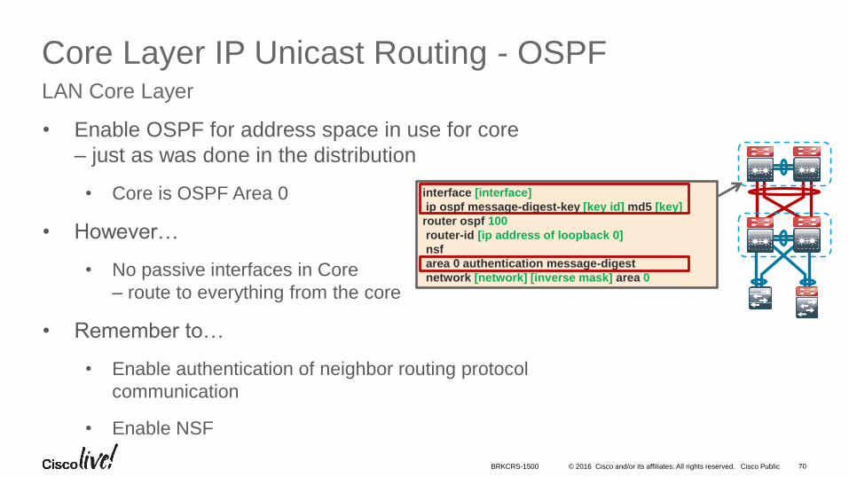
Core Layer IP Unicast Routing - OSPFLAN Core Layer
• Enable OSPF for address space in use for core
– just as was done in the distribution
• Core is OSPF Area 0
• However…
• No passive interfaces in Core
– route to everything from the core
• Remember to…
• Enable authentication of neighbor routing protocol
communication
• Enable NSF
interface [interface]
ip ospf message-digest-key [key id] md5 [key]
router ospf 100
router-id [ip address of loopback 0]
nsf
area 0 authentication message-digest
network [network] [inverse mask] area 0
BRKCRS-1500
© 2016 Cisco and/or its affiliates. All rights reserved. Cisco Public
WAN
71
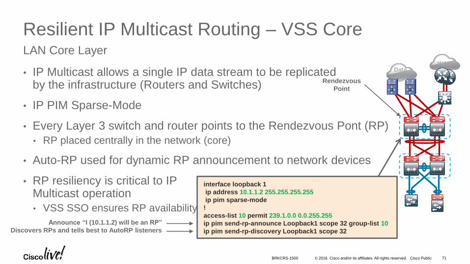
Resilient IP Multicast Routing – VSS Core
• IP Multicast allows a single IP data stream to be replicatedby the infrastructure (Routers and Switches)
• IP PIM Sparse-Mode
• Every Layer 3 switch and router points to the Rendezvous Pont (RP)
• RP placed centrally in the network (core)
• Auto-RP used for dynamic RP announcement to network devices
• RP resiliency is critical to IP Multicast operation
• VSS SSO ensures RP availability
LAN Core Layer
Rendezvous
Point
DataCenter
interface loopback 1
ip address 10.1.1.2 255.255.255.255
ip pim sparse-mode
!
access-list 10 permit 239.1.0.0 0.0.255.255
ip pim send-rp-announce Loopback1 scope 32 group-list 10
ip pim send-rp-discovery Loopback1 scope 32
Announce “I (10.1.1.2) will be an RP”
Discovers RPs and tells best to AutoRP listeners
BRKCRS-1500
© 2016 Cisco and/or its affiliates. All rights reserved. Cisco Public
WAN
72
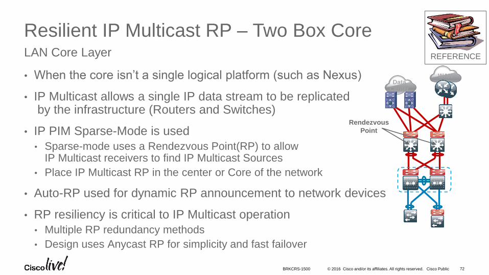
Resilient IP Multicast RP – Two Box Core
• When the core isn’t a single logical platform (such as Nexus)
• IP Multicast allows a single IP data stream to be replicatedby the infrastructure (Routers and Switches)
• IP PIM Sparse-Mode is used
• Sparse-mode uses a Rendezvous Point(RP) to allow IP Multicast receivers to find IP Multicast Sources
• Place IP Multicast RP in the center or Core of the network
• Auto-RP used for dynamic RP announcement to network devices
• RP resiliency is critical to IP Multicast operation
• Multiple RP redundancy methods
• Design uses Anycast RP for simplicity and fast failover
LAN Core Layer
Rendezvous
Point
DataCenter
REFERENCE
BRKCRS-1500
© 2016 Cisco and/or its affiliates. All rights reserved. Cisco Public 73
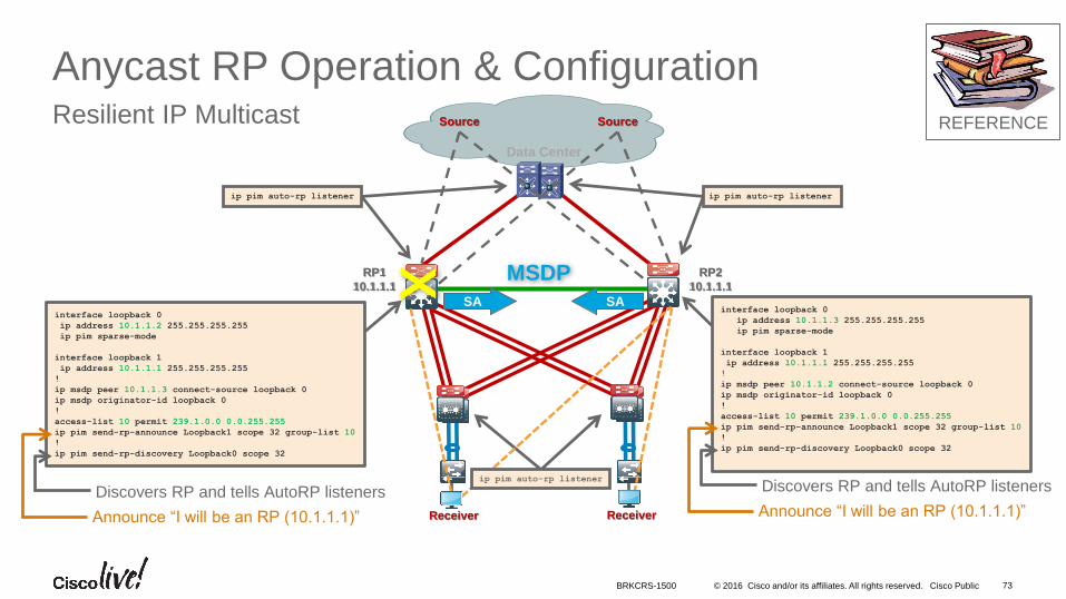
Anycast RP Operation & ConfigurationResilient IP Multicast
MSDPSA SA
Data Center
Source Source
ReceiverReceiver
RP1
10.1.1.1
RP2
10.1.1.1
interface loopback 0
ip address 10.1.1.3 255.255.255.255
ip pim sparse-mode
interface loopback 1
ip address 10.1.1.1 255.255.255.255
!
ip msdp peer 10.1.1.2 connect-source loopback 0
ip msdp originator-id loopback 0
!
access-list 10 permit 239.1.0.0 0.0.255.255
ip pim send-rp-announce Loopback1 scope 32 group-list 10
!
ip pim send-rp-discovery Loopback0 scope 32
interface loopback 0
ip address 10.1.1.2 255.255.255.255
ip pim sparse-mode
interface loopback 1
ip address 10.1.1.1 255.255.255.255
!
ip msdp peer 10.1.1.3 connect-source loopback 0
ip msdp originator-id loopback 0
!
access-list 10 permit 239.1.0.0 0.0.255.255
ip pim send-rp-announce Loopback1 scope 32 group-list 10
!
ip pim send-rp-discovery Loopback0 scope 32
ip pim auto-rp listenerip pim auto-rp listener
X
Announce “I will be an RP (10.1.1.1)”
Discovers RP and tells AutoRP listenersip pim auto-rp listener
Announce “I will be an RP (10.1.1.1)”
Discovers RP and tells AutoRP listeners
REFERENCE
BRKCRS-1500
© 2016 Cisco and/or its affiliates. All rights reserved. Cisco Public
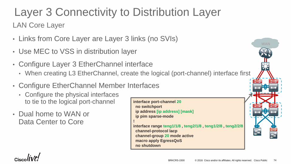
Layer 3 Connectivity to Distribution Layer
• Links from Core Layer are Layer 3 links (no SVIs)
• Use MEC to VSS in distribution layer
• Configure Layer 3 EtherChannel interface
• When creating L3 EtherChannel, create the logical (port-channel) interface first
• Configure EtherChannel Member Interfaces
• Configure the physical interfaces to tie to the logical port-channel
• Dual home to WAN or Data Center to Core
LAN Core Layer
74
interface port-channel 20
no switchport
ip address [ip address] [mask]
ip pim sparse-mode
!
interface range teng1/1/8 , teng2/1/8 , teng1/2/8 , teng2/2/8
channel-protocol lacp
channel-group 20 mode active
macro apply EgressQoS
no shutdown
WAN
BRKCRS-1500
• Introduction to the Campus Wired LAN Deployment CVD
• Access Layer Deployment
• Distribution Layer Deployment
• Core Layer Deployment
• Conclusion
Agenda
© 2016 Cisco and/or its affiliates. All rights reserved. Cisco Public
Would you build this?
76BRKCRS-1500
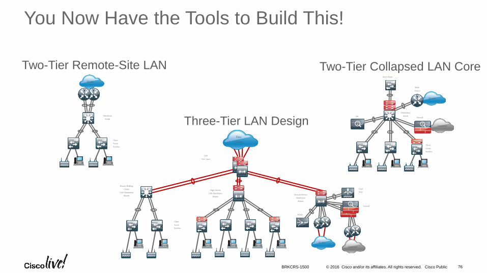
You Now Have the Tools to Build This!
Two-Tier Remote-Site LANWAN
DistributionSwitch
ClientAccessSwitches
Two-Tier Collapsed LAN Core
WAN
Firewall
DistributionSwitch
WANRouter
IPS
ClientAccessSwitches
Server Room
InternetThree-Tier LAN Design
Firewall
High DensityLAN Distribution
Module
GuestWLC
WAAS
WAN
Network-ServicesDistribution
Module
Internet
ClientAccessSwitches
DataCenter
LANCore Layer
Remote BuildingCluster
LAN DistributionModule
© 2016 Cisco and/or its affiliates. All rights reserved. Cisco Public
Summary
• The Cisco Validated Design provides a design framework for the wired campus with step-by-step deployment processes based on the cumulative Cisco leading practices
• Access Layer
• Consistent LAN Access Layer across the network (small site to large campus)
• Supports both layer 2 and layer 3 application needs
• Secure boundary and ready for advanced technologies
• Distribution Layer
• Simplified single logical platform with resilient and scalable design
• Etherchannel for resiliency and scalability
• Core Layer
• Scalable, resilient Layer 3 VSS core for simplified topology and easier configuration, and alternative Nexus 7K option
77
Resiliency, scalability, and flexibility
– easily deployed throughout the network.
BRKCRS-1500
© 2016 Cisco and/or its affiliates. All rights reserved. Cisco Public 78
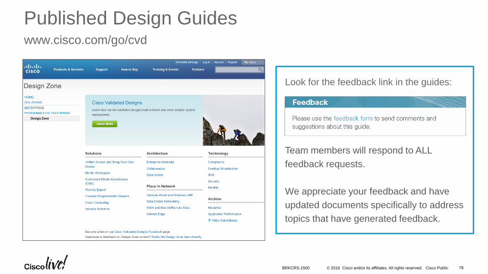
Published Design Guideswww.cisco.com/go/cvd
Look for the feedback link in the guides:
Team members will respond to ALL
feedback requests.
We appreciate your feedback and have
updated documents specifically to address
topics that have generated feedback.
BRKCRS-1500
© 2016 Cisco and/or its affiliates. All rights reserved. Cisco Public
Complete Your Online Session Evaluation
Don’t forget: Cisco Live sessions will be available for viewing on-demand after the event at CiscoLive.com/Online
• Give us your feedback to be entered into a Daily Survey Drawing. A daily winner will receive a $750 Amazon gift card.
• Complete your session surveys through the Cisco Live mobile app or from the Session Catalog on CiscoLive.com/us.
79BRKCRS-1500

© 2016 Cisco and/or its affiliates. All rights reserved. Cisco Public
Continue Your Education
• Demos in the Cisco campus
• Walk-in Self-Paced Labs
• Lunch & Learn
• Meet the Engineer 1:1 meetings
• Related sessions
80BRKCRS-1500
Please join us for the Service Provider Innovation Talk featuring:
Yvette Kanouff | Senior Vice President and General Manager, SP Business
Joe Cozzolino | Senior Vice President, Cisco Services
Thursday, July 14th, 2016
11:30 am - 12:30 pm, In the Oceanside A room
What to expect from this innovation talk
• Insights on market trends and forecasts
• Preview of key technologies and capabilities
• Innovative demonstrations of the latest and greatest products
• Better understanding of how Cisco can help you succeed
Register to attend the session live now or
watch the broadcast on cisco.com

Thank you

www.cisco.com/go/cvd
© 2016 Cisco and/or its affiliates. All rights reserved. Cisco Public 84
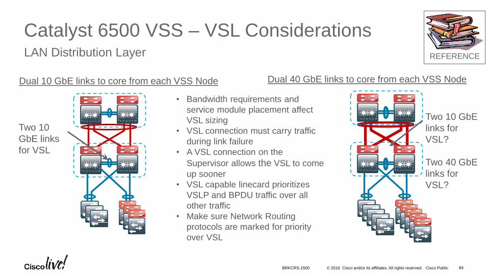
Catalyst 6500 VSS – VSL ConsiderationsLAN Distribution Layer
Dual 10 GbE links to core from each VSS Node Dual 40 GbE links to core from each VSS Node
Two 10
GbE links
for VSL
Two 10 GbE
links for
VSL?
Two 40 GbE
links for
VSL?
• Bandwidth requirements and
service module placement affect
VSL sizing
• VSL connection must carry traffic
during link failure
• A VSL connection on the
Supervisor allows the VSL to come
up sooner
• VSL capable linecard prioritizes
VSLP and BPDU traffic over all
other traffic
• Make sure Network Routing
protocols are marked for priority
over VSL
REFERENCE
BRKCRS-1500
© 2016 Cisco and/or its affiliates. All rights reserved. Cisco Public 85
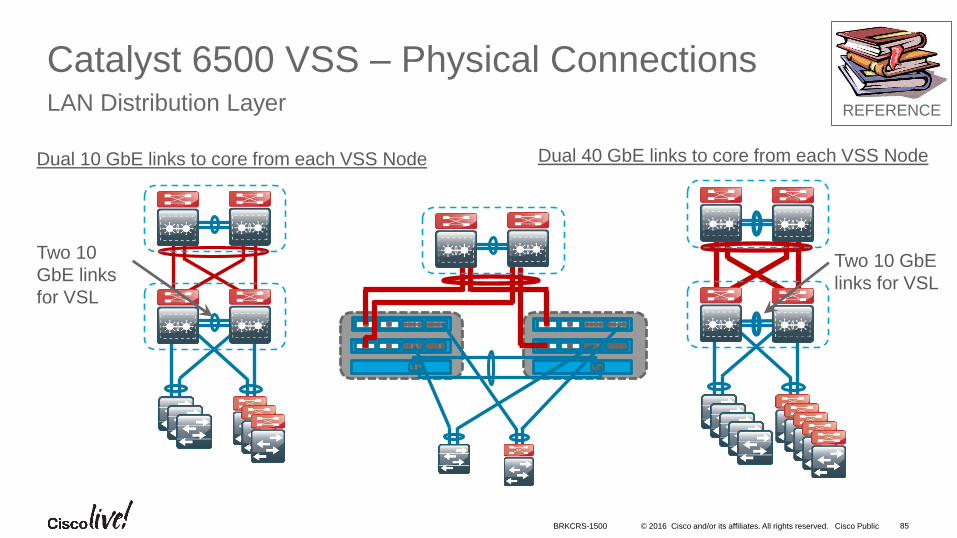
Catalyst 6500 VSS – Physical ConnectionsLAN Distribution Layer
Dual 10 GbE links to core from each VSS Node Dual 40 GbE links to core from each VSS Node
Two 10 GbE
links for VSL
Two 10
GbE links
for VSL
REFERENCE
BRKCRS-1500
© 2016 Cisco and/or its affiliates. All rights reserved. Cisco Public 86
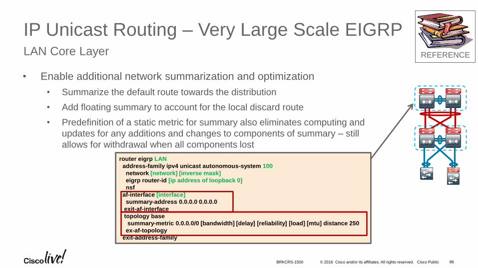
IP Unicast Routing – Very Large Scale EIGRPLAN Core Layer
• Enable additional network summarization and optimization
• Summarize the default route towards the distribution
• Add floating summary to account for the local discard route
• Predefinition of a static metric for summary also eliminates computing and
updates for any additions and changes to components of summary – still
allows for withdrawal when all components lost
router eigrp LAN
address-family ipv4 unicast autonomous-system 100
network [network] [inverse mask]
eigrp router-id [ip address of loopback 0]
nsf
af-interface [interface]
summary-address 0.0.0.0 0.0.0.0
exit-af-interface
topology base
summary-metric 0.0.0.0/0 [bandwidth] [delay] [reliability] [load] [mtu] distance 250
ex-af-topology
exit-address-family
REFERENCE
BRKCRS-1500
© 2016 Cisco and/or its affiliates. All rights reserved. Cisco Public 87
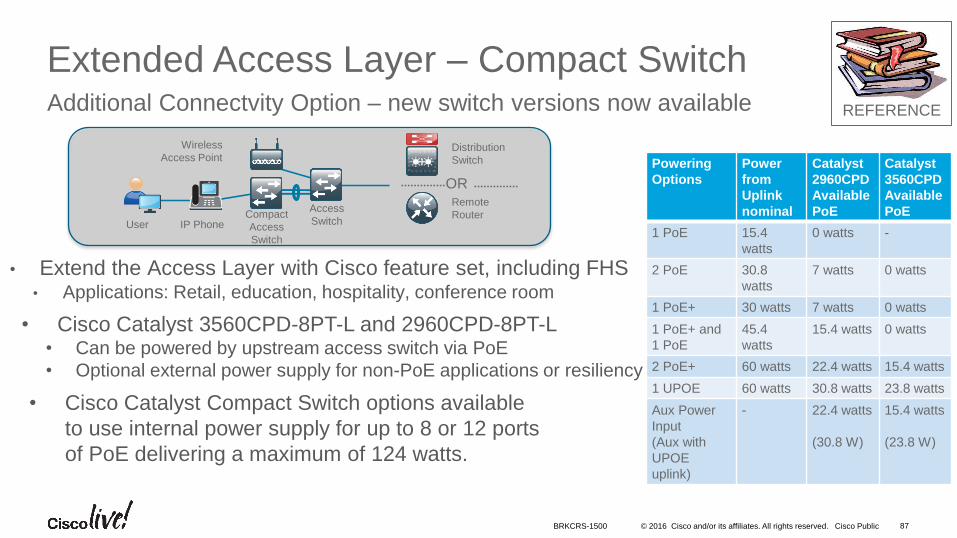
Extended Access Layer – Compact SwitchAdditional Connectvity Option – new switch versions now available
• Extend the Access Layer with Cisco feature set, including FHS• Applications: Retail, education, hospitality, conference room
Wireless
Access Point
User IP Phone
Access
Switch
Distribution
Switch
ORRemote
RouterCompact
Access
Switch
Powering
Options
Power
from
Uplink
nominal
Catalyst
2960CPD
Available
PoE
Catalyst
3560CPD
Available
PoE
1 PoE 15.4
watts
0 watts -
2 PoE 30.8
watts
7 watts 0 watts
1 PoE+ 30 watts 7 watts 0 watts
1 PoE+ and
1 PoE
45.4
watts
15.4 watts 0 watts
2 PoE+ 60 watts 22.4 watts 15.4 watts
1 UPOE 60 watts 30.8 watts 23.8 watts
Aux Power
Input
(Aux with
UPOE
uplink)
- 22.4 watts
(30.8 W)
15.4 watts
(23.8 W)
• Cisco Catalyst 3560CPD-8PT-L and 2960CPD-8PT-L • Can be powered by upstream access switch via PoE
• Optional external power supply for non-PoE applications or resiliency
• Cisco Catalyst Compact Switch options available
to use internal power supply for up to 8 or 12 ports
of PoE delivering a maximum of 124 watts.
REFERENCE
BRKCRS-1500


![MULTI CHANNEL AV RECEIVER STR-DN1080 - Sonyhelpguide.sony.net/ha/strdn108/v1/en/print.pdfWhat you can do with network features [83] Setting up a wired LAN connection (for wired LAN](https://img.pdfslide.us/doc/110x75/5b21c0e37f8b9a235d8b464b/multi-channel-av-receiver-str-dn1080-you-can-do-with-network-features-83-setting.jpg)

![Network Set-up and Operation [LX505/LX605] · Connect the LAN cable to the LAN connection terminal of the projector. Network configuration Set the Wired LAN network through the projector](https://img.pdfslide.us/doc/110x75/604e8f782ee1367f52780519/network-set-up-and-operation-lx505lx605-connect-the-lan-cable-to-the-lan-connection.jpg)